WO2021241297A1 - 画像表示装置及び投射光学系 - Google Patents
画像表示装置及び投射光学系 Download PDFInfo
- Publication number
- WO2021241297A1 WO2021241297A1 PCT/JP2021/018550 JP2021018550W WO2021241297A1 WO 2021241297 A1 WO2021241297 A1 WO 2021241297A1 JP 2021018550 W JP2021018550 W JP 2021018550W WO 2021241297 A1 WO2021241297 A1 WO 2021241297A1
- Authority
- WO
- WIPO (PCT)
- Prior art keywords
- image
- image display
- light
- display device
- reflecting surface
- Prior art date
- Legal status (The legal status is an assumption and is not a legal conclusion. Google has not performed a legal analysis and makes no representation as to the accuracy of the status listed.)
- Ceased
Links
Images


Classifications
-
- G—PHYSICS
- G03—PHOTOGRAPHY; CINEMATOGRAPHY; ANALOGOUS TECHNIQUES USING WAVES OTHER THAN OPTICAL WAVES; ELECTROGRAPHY; HOLOGRAPHY
- G03B—APPARATUS OR ARRANGEMENTS FOR TAKING PHOTOGRAPHS OR FOR PROJECTING OR VIEWING THEM; APPARATUS OR ARRANGEMENTS EMPLOYING ANALOGOUS TECHNIQUES USING WAVES OTHER THAN OPTICAL WAVES; ACCESSORIES THEREFOR
- G03B21/00—Projectors or projection-type viewers; Accessories therefor
- G03B21/14—Details
- G03B21/28—Reflectors in projection beam
-
- G—PHYSICS
- G02—OPTICS
- G02B—OPTICAL ELEMENTS, SYSTEMS OR APPARATUS
- G02B17/00—Systems with reflecting surfaces, with or without refracting elements
- G02B17/08—Catadioptric systems
- G02B17/082—Catadioptric systems using three curved mirrors
- G02B17/0832—Catadioptric systems using three curved mirrors off-axis or unobscured systems in which not all of the mirrors share a common axis of rotational symmetry, e.g. at least one of the mirrors is warped, tilted or decentered with respect to the other elements
-
- G—PHYSICS
- G03—PHOTOGRAPHY; CINEMATOGRAPHY; ANALOGOUS TECHNIQUES USING WAVES OTHER THAN OPTICAL WAVES; ELECTROGRAPHY; HOLOGRAPHY
- G03B—APPARATUS OR ARRANGEMENTS FOR TAKING PHOTOGRAPHS OR FOR PROJECTING OR VIEWING THEM; APPARATUS OR ARRANGEMENTS EMPLOYING ANALOGOUS TECHNIQUES USING WAVES OTHER THAN OPTICAL WAVES; ACCESSORIES THEREFOR
- G03B21/00—Projectors or projection-type viewers; Accessories therefor
- G03B21/54—Accessories
- G03B21/56—Projection screens
- G03B21/60—Projection screens characterised by the nature of the surface
-
- H—ELECTRICITY
- H04—ELECTRIC COMMUNICATION TECHNIQUE
- H04N—PICTORIAL COMMUNICATION, e.g. TELEVISION
- H04N9/00—Details of colour television systems
- H04N9/12—Picture reproducers
- H04N9/31—Projection devices for colour picture display, e.g. using electronic spatial light modulators [ESLM]
- H04N9/3102—Projection devices for colour picture display, e.g. using electronic spatial light modulators [ESLM] using two-dimensional electronic spatial light modulators
- H04N9/3105—Projection devices for colour picture display, e.g. using electronic spatial light modulators [ESLM] using two-dimensional electronic spatial light modulators for displaying all colours simultaneously, e.g. by using two or more electronic spatial light modulators
-
- H—ELECTRICITY
- H04—ELECTRIC COMMUNICATION TECHNIQUE
- H04N—PICTORIAL COMMUNICATION, e.g. TELEVISION
- H04N9/00—Details of colour television systems
- H04N9/12—Picture reproducers
- H04N9/31—Projection devices for colour picture display, e.g. using electronic spatial light modulators [ESLM]
- H04N9/3141—Constructional details thereof
- H04N9/3147—Multi-projection systems
-
- G—PHYSICS
- G03—PHOTOGRAPHY; CINEMATOGRAPHY; ANALOGOUS TECHNIQUES USING WAVES OTHER THAN OPTICAL WAVES; ELECTROGRAPHY; HOLOGRAPHY
- G03B—APPARATUS OR ARRANGEMENTS FOR TAKING PHOTOGRAPHS OR FOR PROJECTING OR VIEWING THEM; APPARATUS OR ARRANGEMENTS EMPLOYING ANALOGOUS TECHNIQUES USING WAVES OTHER THAN OPTICAL WAVES; ACCESSORIES THEREFOR
- G03B37/00—Panoramic or wide-screen photography; Photographing extended surfaces, e.g. for surveying; Photographing internal surfaces, e.g. of pipe
- G03B37/04—Panoramic or wide-screen photography; Photographing extended surfaces, e.g. for surveying; Photographing internal surfaces, e.g. of pipe with cameras or projectors providing touching or overlapping fields of view
Definitions
- This technology relates to an image display device such as a projector and a projection optical system, for example.
- a projector is widely known as a projection type image display device that displays a projected image on a screen.
- a projector is widely known as a projection type image display device that displays a projected image on a screen.
- ultra-wide-angle front projection projectors that can display a large screen even if the projection space is small.
- this projector it is possible to project a large screen in a limited space by hitting it diagonally and at a wide angle with respect to the screen.
- the purpose of this technology is to provide an image display device and a projection optical system that can support an ultra-wide angle and can realize high-quality image display.
- the image display device includes a light source, an image generation unit, and a projection optical system.
- the image generation unit modulates the light emitted from the light source to generate image light.
- the projection optical system has a lens system and a concave reflection surface.
- the lens system is configured with reference to a reference axis at a position where the generated image light is incident, and has a positive refractive power as a whole.
- the concave reflecting surface is configured with reference to the reference axis, and reflects the image light emitted from the lens system toward the projectile.
- the image display device is The height of the light beam from the reference axis is h,
- the angle of the tangent of the function Z (h) representing the shape of the concave reflecting surface corresponding to the light ray height h with respect to the height direction of the optical axis is ⁇ (h).
- the amount of change in the angle ⁇ (h) at the ray height h is ⁇ (h)
- the shape of the concave reflecting surface that reflects the image light toward the projectile is designed as described above. This makes it possible to realize high-quality image display.
- the ⁇ (h) may be ⁇ (h) ⁇ (0.98 ⁇ h).
- the projection optical system is formed on the concave reflection surface. It may be configured so that the traveling directions of the incident edge-side rays are parallel to each other.
- the projection optical system may be configured so that the distance between the edge-side light rays incident on the concave reflection surface is equal.
- the lens system may have a first refraction optical system, a first reflection surface, a second reflection surface, and a second refraction optical system.
- the first refractive optics system has a positive refractive power as a whole and refracts the generated image light.
- the first reflecting surface folds back and reflects the image light refracted by the first refractive optics system.
- the second reflecting surface folds back and reflects the image light reflected by the first reflecting surface.
- the second refracting optical system has a positive refractive power as a whole, refracts the image light reflected by the second reflecting surface, and emits the image light to the concave reflecting surface.
- the image display device is The power of the first reflecting surface is ⁇ 1, Assuming that the power of the second reflecting surface is ⁇ 2, 0.1 ⁇
- the image display device may be configured to satisfy the relationship of
- the image display device is Of the edge-side rays, a ray having an intermediate value at the height of the reflection point reflected by the concave reflecting surface is referred to as an intermediate ray.
- the position of the intermediate light beam incident on the final lens surface of the second refractive optics is defined as the intermediate incident position.
- the optical path length from the image generation unit of the intermediate ray to the predetermined condensing position is A.
- the optical path length from the intermediate incident position to the front focal length is B, Let C be the optical path length from the image generation unit of the intermediate ray to the intermediate incident position. 0.8 ⁇ A + B
- the average angle is the average value of the angles at which the traveling directions of the edge-side rays incident on the concave reflecting surface intersect with the directions along the reference axis. Assuming that the region where the edge-side light rays are incident on the final lens surface of the second refractive optics is the edge-side incident region.
- the front focal position of the second optical system is parallel to the edge-side incident region of the final lens surface from the opposite side along a direction intersecting the direction along the reference axis at the average angle. It may be a condensing position when a light beam is incident.
- the optical path length B may be the optical path length of the light rays traveling from the intermediate incident position to the rear focal position when a parallel light ray is incident on the edge side incident region of the final lens surface from the opposite side. good.
- the concave reflecting surface may reflect at least a part of the light rays contained in the image light incident on the concave reflecting surface in a direction intersecting the direction along the reference axis at an angle of 90 degrees or more.
- the projection optical system may have a first optical component in which a part of the main surface is configured as the first reflecting surface and a transmission surface is formed in another region of the main surface.
- the transmission surface of the first optical component may function as the second refractive optics system.
- the projection optical system may have a second optical component in which a part of the main surface is configured as the second reflecting surface and a transmission surface is formed in another region of the main surface.
- the transmission surface of the second optical component may function as the first refractive optics system.
- the reference axis may be an axis extending the optical axis of the lens closest to the image generation unit included in the lens system.
- the projection optical system may be configured so that the optical axes of all the optical components included in the projection optical system coincide with a predetermined reference axis.
- the concave reflective surface may be configured so that the axis of rotational symmetry coincides with the reference axis.
- each of the first reflecting surface and the second reflecting surface is a concave reflecting surface, and may be configured so that the axis of rotational symmetry coincides with the reference axis.
- Each of the concave reflecting surface, the first reflecting surface, and the second reflecting surface may be configured so that the optical axis coincides with the reference axis.
- at least one of the concave reflecting surface, the first reflecting surface, or the second reflecting surface may be a free curved surface having no axis of rotational symmetry.
- the projectile may be a flat screen or a curved screen.
- the projectile may be a screen having a dome shape.
- the projection optical system according to one embodiment of the present technology is a projection optical system that projects image light generated by modulating light emitted from a light source, and includes the lens system and the concave reflection surface. ..
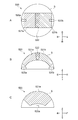
- FIG. It is a schematic diagram for demonstrating the configuration condition 1.
- FIG. It is a schematic diagram for demonstrating the configuration condition 2.
- the outline of the projection type image display device will be briefly described by taking a liquid crystal projector as an example.
- the liquid crystal projector spatially modulates the light emitted from the light source to form an optical image (image light) corresponding to the video signal.
- a liquid crystal display element or the like which is an image modulation element, is used for light modulation.
- a three-panel liquid crystal projector equipped with a panel-shaped liquid crystal display element (liquid crystal panel) corresponding to each of RGB is used.
- the optical image is magnified and projected by the projection optical system and displayed on the screen.
- the projection optical system corresponds to, for example, an ultra-wide angle with a half angle of view of 70 ° or more. Of course, it is not limited to this angle.
- a liquid crystal projector that supports an ultra-wide angle can display a large screen even in a small projection space. That is, even if the distance between the liquid crystal projector and the screen is short, magnified projection is possible.
- This has the following advantages. Since the liquid crystal projector can be placed close to the screen, it is possible to sufficiently suppress the possibility that the light from the liquid crystal projector directly enters the human eye, and high safety is exhibited. Efficient presentations are possible because shadows of humans and the like do not appear on the screen. It has a high degree of freedom in selecting the installation location, and can be easily installed even in a narrow installation space or a ceiling with many obstacles. By installing it on the wall and using it, maintenance such as cable routing is easier than when installing it on the ceiling. For example, it is possible to increase the degree of freedom in setting the meeting space, classroom, conference room, and the like.
- FIG. 1 is a schematic diagram for explaining other advantages of an ultra-wide-angle LCD projector. As shown in FIG. 1, by installing an ultra-wide-angle compatible liquid crystal projector 1 on a table, it is possible to project an enlarged image 2 on the same table. This kind of usage is also possible, and the space can be used efficiently.
- an ultra-wide-angle LCD projector is also called a short-focus projector, an ultra-short-focus projector, or the like.
- FIG. 2 is a schematic view showing a configuration example of a projection type image display device.
- the image display device 20 includes a light source 5, an illumination optical system 10, and a projection optical system 15.
- the light source 5 is arranged so as to emit a luminous flux with respect to the illumination optical system 10.
- a high-pressure mercury lamp or the like is used as the light source 5.
- a solid-state light source such as an LED (Light Emitting Diode) or an LD (Laser Diode) may be used.
- the illumination optical system 10 uniformly irradiates the surface of the image modulation element (liquid crystal panel P), which is the primary image plane, with the light flux emitted from the light source 5.
- the luminous flux from the light source 5 passes through the two fly-eye lens FL, the polarization conversion element PS, and the condenser lens L in order, and is converted into a uniform luminous flux with uniform polarization.
- the luminous flux that has passed through the condenser lens L is separated into RGB color component light by a dichroic mirror DM that reflects only light in a specific wavelength band.
- Each color component light of RGB is incident on a liquid crystal panel P (image modulation element) provided corresponding to each color of RGB via a total reflection mirror M, a lens L, or the like. Then, each liquid crystal panel P performs optical modulation according to the video signal. The light-modulated color component light is combined by the dichroic prism PP to generate image light. Then, the generated image light is emitted toward the projection optical system 15.
- a liquid crystal panel P image modulation element
- the optical components and the like constituting the illumination optical system 10 are not limited, and optical components different from the optical components described above may be used.
- a reflective liquid crystal panel, a digital micromirror device (DMD), or the like may be used instead of the transmissive liquid crystal panel P.
- DMD digital micromirror device
- a polarizing beam splitter (PBS) instead of the dichroic prism PP, a polarizing beam splitter (PBS), a color synthesis prism for synthesizing video signals of each RGB color, a TIR (Total Internal Reflection) prism, or the like may be used.
- the illumination optical system 10 corresponds to an image generation unit.
- the projection optical system 15 adjusts the image light emitted from the illumination optical system 10 and performs magnified projection on a screen serving as a secondary image plane. That is, the image information of the primary image plane (liquid crystal panel P) is adjusted by the projection optical system 15, and the image information is magnified and projected onto the secondary image plane (screen).
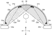
- FIG. 3 and 4 are schematic views showing a configuration example of an image display system according to a first embodiment of the present technology.
- FIG. 3 is a view of the image display system 100 as viewed from above.
- FIG. 4 is a view of the image display system 100 viewed obliquely from above on the right front side.
- the image display system 100 includes a curved screen 30 and two image display devices 20.
- the curved screen 30 includes both a screen having a curved surface shape as a whole and a screen having a curved surface shape having at least a part of the curved surface shape.
- a curved screen 30 having a substantially arc shape when viewed from above is used.
- the curved screen 30 is erected along the vertical direction and is installed so as to extend in the horizontal direction.
- the left and right end portions 31a and 31b of the curved screen 30 are bent forward and arranged at substantially equal positions in the front-rear direction.
- the substantially central portion of the curved screen 30 in the left-right direction is located at the rearmost side and corresponds to the apex of the substantially arc shape seen from above.
- the shape of the curved screen 30 is substantially equal to a part of the inner surface of a cylinder erected along the vertical direction. Further, the curved screen 30 may be configured by connecting minute plane regions while changing their angles. The specific configuration of the curved screen 30, such as the material, size, and radius of curvature, is not limited and may be arbitrarily designed. Further, the curved screen 30 may be realized by adhering a flexible screen member to the inner surface of the substrate portion having an arc shape when viewed from above. In the present embodiment, the curved screen 30 corresponds to a projectile.
- the two image display devices 20 include a first image display device 20a and a second image display device 20b.
- the first image display device 20a is installed so as to be able to project an image rearward at a substantially central portion in the vertical direction of the left end portion 31a of the curved screen 30.
- the first image display device 20a projects an image (hereinafter referred to as a first image) 21a on a region on the left side of a curved screen 30 bent in a substantially arc shape.
- the second image display device 20b is installed so as to be able to project an image rearward at a substantially central portion in the vertical direction of the right end portion 31b of the curved screen 30.
- the second image display device 20b projects an image (hereinafter referred to as a second image) 21b on a region on the right side of the curved screen 30 bent in a substantially arc shape.
- a second image an image
- the first and second image display devices 20a and 20b have the first and second images 21a and 20b so that the first and second images 21a and 21b overlap each other. 21b are projected respectively.
- the holding mechanism (not shown) for holding the first and second image display devices 20a and 20b may be arbitrarily designed.
- the image modulation element (liquid crystal panel P) provided in the first and second image display devices 20a and 20b has a rectangular shape having a long side direction and a short side direction. Then, the liquid crystal panel P generates image light that constitutes a rectangular image.
- the first and second images 21a and 21b are projected as rectangular images equal to each other, respectively. Then, the first and second images 21a and 21b are projected along the long side direction (left-right direction) of the first and second images 21a and 21b so as to overlap each other, respectively. Therefore, an overlapping region 22 in which the first and second images 21a and 21b overlap each other is generated in the substantially central portion of the curved screen 30.
- the stitching process is executed in the overlapping region 22 where the first and second images 21a and 21b overlap.
- the first and second images 21a and 21b are connected and combined as one image.
- one large-sized image is displayed in substantially the entire area along the left-right direction of the curved screen 30.
- the specific algorithm of the stitching process is not limited, and any stitching technique may be used.
- the first image light 23a constituting the first image 21a projected from the first image display device 20a and the pixel lights Ca1, Ca2, and Ca3 included in the first image light 23a are schematically shown. Is illustrated in. Further, in FIG. 3, the first image light 23b constituting the second image 21b projected from the second image display device 20b and the pixel lights Cb1, Cb2, and Cb3 included in the second image light 23b are schematically shown. Is illustrated.
- the pixel light is light for forming each of a plurality of pixels included in the projected image. Typically, the light emitted from each of the plurality of pixels included in the image modulation element (liquid crystal panel P) that generates and emits image light becomes the pixel light. Therefore, the image light includes a plurality of pixel lights.
- the pixel light Ca1 shown in FIG. 3 is pixel light for forming the pixel at the left end of the first image 21a. Therefore, the pixel light Ca1 corresponds to the light ray at the left end of the first image light 23a.
- the pixel light Ca2 is pixel light for forming the pixel at the right end of the first image 21a. Therefore, the pixel light Ca2 corresponds to the light ray at the right end of the first image light 23a.
- the pixel light Ca3 is pixel light for forming the pixel at the left end of the overlapping region 22 where the first and second images 21a and 21b overlap.
- the light rays from the pixel lights Ca3 to Ca2 are the image lights constituting the overlapping region 22.
- the light rays from the pixel lights Ca1 to Ca3 are image lights constituting a region other than the overlapping region 22.
- the pixel light Cb1 shown in FIG. 3 is pixel light for forming the pixel at the right end of the second image 21b. Therefore, the pixel light Cb1 corresponds to the light ray at the right end of the second image light 23b.
- the pixel light Cb2 is pixel light for forming the pixel at the left end of the second image 21b. Therefore, the pixel light Cb2 corresponds to the light ray at the left end of the first image light 23a.
- the pixel light Ca3 is pixel light for forming the pixel at the right end of the overlapping region 22. Therefore, among the light rays included in the second image light 23b, the light rays from the pixel lights Cb3 to Cb2 are the image lights constituting the overlapping region 22. On the other hand, among the light rays included in the second image light 23b, the light rays from the pixel lights Cb1 to Cb3 are image lights constituting a region other than the overlapping region 22.
- the first and second image display devices 20a and 20b form an image other than the overlapping area 22 in which the first and second images 21a and 21b overlap each other.
- the first and second images 21a and 21b are projected, respectively, so that the light does not intersect each other.
- the user 3 views the first and second images 21a and 21b combined into one image from the inner region (for example, a position close to the overlapping region 22) of the curved screen 30 bent into an arc shape. It becomes possible.
- the direction in which the first and second images 21a and 21b overlap is not limited.
- the first and second images 21a and 21b may be projected along the short side direction of the first and second images 21a and 21b so as to overlap each other, respectively.
- rectangular first and second images 21a and 21b having the left-right direction as the short side direction are projected.
- the first and second images 21a and 21b are projected so that the first and second images 21a and 21b overlap along the short side direction of the first and second images 21a and 21b. good.
- the image when the image light constituting the rectangular image is projected, the image may be displayed in a shape different from the rectangular shape.
- the direction corresponding to the long side direction and the short side direction of the liquid crystal panel P can be defined as the long side direction and the short side direction of the image. Then, it is possible to overlap a plurality of images along the long side direction or the short side direction.
- the long side direction and the short side direction of the liquid crystal panel P may be expressed as the long side direction and the short side direction of the image light.
- first and second image display devices 20a and 20b image display devices having substantially the same configuration as each other are used.
- the projection optical system 15 of the first and second image display devices 20a and 20b will be described.
- FIGS. 5 and 6 are optical path diagrams showing a schematic configuration example of the projection optical system 15 according to the present embodiment.
- FIG. 6 shows one projection optical system 15 and a portion on which the image of the curved screen S is projected.
- an image display system 100 having a curved screen 30 and first and second image display devices 20a and 20b shown in FIGS. 3 and 4 can be obtained. It is possible to achieve it.
- the liquid crystal panel P and the dichroic prism PP of the illumination optical system 10 are schematically illustrated.
- the emission direction of the image light emitted from the dichroic prism PP to the projection optical system 15 is defined as the Z direction.
- the horizontal direction of the primary image plane (liquid crystal panel P) is the X direction
- the vertical direction is the Y direction.
- the X and Y directions are directions corresponding to the horizontal and vertical directions of the image composed of the image light.
- the description may be made with the Z direction (the emission direction of the image light) in the drawing as the left-right direction and the Y direction as the up-down direction.
- the emission direction of the image light is not limited, and the direction and posture of the image display device 20 can be arbitrarily set.
- FIGS. 5 and 6 show cross-sectional shapes of optical surfaces (lens surface, reflective surface, etc.) of each optical component included in the projection optical system 15.
- hatching or the like representing a cross section of each optical component is omitted.
- the projection optical system 15 includes a lens system L and a concave reflection surface Mr3.
- the lens system L is configured at a position where the image light generated by the illumination optical system 10 is incident, and has a positive refractive power as a whole.
- the lens system L is configured with reference to a reference axis extending in the Z direction (hereinafter, this reference axis is referred to as an optical axis O).
- this reference axis is referred to as an optical axis O).
- the lens system L is configured such that the optical axis of each of the one or more optical components included in the lens system L substantially coincides with the optical axis O which is the reference axis.
- the optical axis of the optical component is typically an axis that passes through the center of the optical surface of the optical component.
- the axis of rotational symmetry corresponds to the optical axis.
- only a part of the optical component arranged so that its optical axis coincides with the optical axis O, including the effective region, which is the region where the image light is incident, may be used. By using a part of the optical component, it is possible to reduce the size of the projection optical system 15.
- the optical axis O is an extension of the optical axis (rotational symmetry axis) of the lens L11, which is included in the optical system L and is closest to the illumination optical system 10. That is, other optical components are arranged on the axis extending the optical axis of the lens L11.
- the image light is emitted along the optical axis O from a position offset upward from the optical axis O.
- the Z direction along the optical axis O can also be referred to as the optical path traveling direction of the lens system L.
- the lens system L has a first refraction optical system L1, a first reflection surface Mr1, a second reflection surface Mr2, and a second refraction optical system L2.
- the first refracting optical system L1 has a positive refractive power as a whole and refracts the image light generated by the illumination optical system 10.
- the image light of the lens L12 arranged at the position closest to the first reflecting surface Mr1 is incident from the incident surface F1 on which the image light of the lens L11 arranged at the position closest to the illumination optical system 10 is incident. Up to the exit surface F2 to be emitted functions as the first refraction optical system L1.
- the first reflecting surface Mr1 is a concave reflecting surface, and is a rotationally symmetric aspherical surface configured so that the axis of rotational symmetry coincides with the optical axis O.
- the first reflecting surface Mr1 is arranged on the lower side of the optical axis O, and reflects the image light refracted by the first refracting optical system L1 by folding back. Specifically, the image light incident from the left side is folded back toward the upper left and reflected.
- the first optical component R11 is arranged so that the axis of rotational symmetry coincides with the optical axis O.
- the first reflecting surface Mr1 is configured in a part of the lower region of the rotationally symmetric aspherical surface F3 corresponding to the main surface of the first optical component R11. Conversely, a part of the lower region of the rotationally symmetric aspherical surface F3 is configured as the first reflecting surface Mr1.
- a transmission surface Tr2 is formed in another region of the rotationally symmetric aspherical surface F3 of the first optical component R11.
- the second reflecting surface Mr2 is a concave reflecting surface, and is a rotationally symmetric spherical surface configured so that the axis of rotational symmetry coincides with the optical axis O.
- the second reflecting surface Mr2 is arranged on the upper side of the optical axis O, and the image light reflected by the first reflecting surface Mr1 is folded back and reflected toward the second refractive optical system L2. Specifically, the image light incident from the lower right is folded back toward the right side and reflected.
- the second optical component R12 is arranged so that the axis of rotational symmetry coincides with the optical axis O.
- the second reflecting surface Mr2 is configured in a part of the upper region of the rotational symmetry surface F4 corresponding to the main surface of the second optical component R12. Conversely, a part of the region on the upper side of the rotational symmetry plane F4 is configured as the second reflection plane Mr2.
- a transmission surface Tr1 is formed in another region of the rotation symmetry surface F4 of the second optical component R12.
- the transmission surface Tr2 formed on the rotationally symmetric aspherical surface F3 of the first optical component R11 functions as the second refractive optics system L2.
- the transmission surface Tr1 formed on the rotation symmetry surface F4 of the second optical component R12 functions as the first refractive optics system L1.
- one optical component realizes the first reflecting surface Mr1 and the optical surface (transmission surface Tr2) that functions as the second refractive optics system L2.
- a second reflection surface Mr2 and an optical surface (transmission surface Tr1) that functions as the first refractive optics system L1 are realized. This makes it possible to reduce the size of the projection optical system 15. Further, it is possible to improve the assembly accuracy of the projection optical system 15.
- the second refracting optical system L2 has a positive refractive index as a whole, refracts the image light reflected by the second reflecting surface Mr2, and emits it to the concave reflecting surface Mr3.
- the second refraction is from the transmission surface Tr2 formed on the first optical component R11 to the emission surface F5 from which the image light of the lens L21 arranged at the position closest to the concave reflection surface Mr3 is emitted. It functions as an optical system L2.
- the emission surface F5 of the lens L21 is the final lens surface of the second refractive optics system L2.
- the emission surface F5 may be referred to as the final lens surface F5 using the same reference numerals.
- the concave reflecting surface Mr3 is configured with reference to the optical axis O, which is a reference axis, and reflects the image light emitted from the lens system L toward the curved screen S.
- the concave reflecting surface Mr3 is a rotationally symmetric aspherical surface configured so that the axis of rotational symmetry (optical axis) coincides with the optical axis O, and the effective region, which is the region where the image light is incident, is composed of only the reflective portion. Has been done. That is, instead of arranging the entire rotationally symmetric aspherical surface, only the necessary part of the rotationally symmetric aspherical surface is arranged. This makes it possible to reduce the size of the device.
- the first refraction optical system L1, the first reflection surface Mr1, the second reflection surface Mr2, the second refraction optical system L2, and the concave reflection surface Mr3 are configured on the common optical axis O. Will be done. Therefore, the first refraction optical system L1 and the first refraction optical system L1 so that the axis extending the optical axis (rotational symmetry axis) of the lens L11 arranged at the position closest to the illumination optical system 10 coincides with each optical axis.
- the reflection surface Mr1, the second reflection surface Mr2, the second refraction optical system L2, and the concave reflection surface Mr3 are configured.
- the optical axes of all the optical components included in the projection optical system 15 are configured to coincide with the optical axis O. This makes it possible to reduce the size in the Y direction and to reduce the size of the device.
- the projection optical system 15 may include an optical component whose optical axis is offset from the optical axis O.
- FIGS. 5 and 6 show the optical paths of three pixel lights C1, C2, and C3 among the image lights emitted from the dichroic prism PP to the projection optical system 15.
- the pixel light is emitted as divergent light from the pixels of the liquid crystal panel P.
- the emitted pixel light is imaged on the curved screen S by the projection optical system 15 and displayed as pixels of the projection image.
- the component light emitted along the optical axis O of each pixel light (along the Z direction) is used as the main light ray.
- Each pixel light is imaged at a position where the main ray is incident on the curved screen S.
- FIG. 5 as each pixel light, a main ray and a maximum divergent light above and below are shown.
- the pixel light C1 corresponds to the pixel light emitted from the central pixel of the liquid crystal panel P.
- the pixel light C2 corresponds to the pixel light emitted from the pixel closest to the optical axis O in the center of the liquid crystal panel P.
- the pixel light C3 corresponds to the pixel light emitted from the pixel farthest from the optical axis O in the center of the liquid crystal panel P. That is, in the present embodiment, the pixel light C2 corresponds to the pixel light emitted from the pixel closest to the optical axis O of the liquid crystal panel P.
- the pixel light C3 is located on a straight line connecting the pixel closest to the optical axis O to the central pixel of the liquid crystal panel P, and corresponds to the pixel light emitted from the pixel farthest from the optical axis O.
- the image light emitted from the position offset upward from the optical axis O to the projection optical system 15 along the optical axis O intersects the optical axis O in the first refraction optical system L1. Then, it proceeds downward and is incident on the first reflecting surface Mr1.
- the image light incident on the first reflecting surface Mr1 is folded back by the first reflecting surface Mr1, crosses the optical axis O again, travels upward, and is incident on the second reflecting surface Mr2.
- the image light incident on the second reflecting surface Mr2 is folded back by the second reflecting surface Mr2 and is incident on the second refractive optics system L2.
- the image light crosses the optical axis O again and travels downward, and is emitted toward the concave reflection surface Mr3.
- the image light emitted from the second refraction optical system L1 is reflected upward by the concave reflecting surface Mr3, intersects the optical axis O again, and is projected toward the curved screen S.
- the optical path of the image light is configured so as to intersect the optical axis O.
- the optical path of the image light up to the concave reflection surface Mr3 can be configured in the vicinity of the optical axis O.
- the image light is folded back and reflected by each of the first reflecting surface Mr1 and the second reflecting surface Mr2. This makes it possible to secure a sufficient optical path length of the image light.
- a plurality of intermediate images are formed between the dichroic prism PP included in the illumination optical system 10 and the concave reflection surface Mr3.
- the intermediate image is an intermediate image of an image composed of image light. This makes it possible to project image light at an ultra-wide angle. For example, it is possible to display a large screen even when the distance between the projector and the screen is short.
- the optical path length of the image light can be sufficiently secured by the first reflecting surface Mr1 and the second reflecting surface Mr2, it is possible to accurately correct the image. Is. That is, it is possible to generate an appropriate intermediate image, and it is possible to easily form a high-precision image on the screen. Further, since the optical path length is sufficiently secured, it is possible to suppress the optical load required to generate an appropriate intermediate image, and the optical power of each optical component included in the projection optical system 15 is suppressed. It is possible. As a result, it is possible to reduce the size of each optical component, and it is possible to reduce the size of the entire device. Further, since a plurality of intermediate images are formed in the projection optical system 15, it is possible to accurately generate an optimum intermediate image. As a result, the concave reflecting surface Mr3 makes it possible to display a highly accurate image on the screen. By using the projection optical system 15 according to the present embodiment in this way, it is possible to realize high performance of the apparatus.
- the concave reflecting surface Mr3 due to the concave reflecting surface Mr3, at least a part of the light rays included in the image light incident on the concave reflecting surface Mr3 is along the optical axis O which is the reference axis. It is reflected in the direction that intersects the direction at an angle of 90 degrees or more.
- the crossing angle between the traveling direction of the light rays included in the image light reflected by the concave reflecting surface Mr3 and the direction along the optical axis O is defined as follows. First, the intersection of the straight line extending along the optical axis O and the straight line extending along the traveling direction of the light ray reflected by the concave reflecting surface Mr3 is calculated.
- a straight line extending from the intersection to the liquid crystal panel P side is rotated in the traveling direction side of the light beam with the intersection as a reference.
- the traveling angle of the light ray included in the image light reflected by the concave reflecting surface Mr3 is set to the rotation angle until the straight line extending on the liquid crystal panel P side coincides with the straight line extending along the traveling direction of the light ray. It is defined as the intersection angle between the direction and the direction along the optical axis O.
- the concave reflecting surface Mr3 is designed so that the crossing angle of at least a part of the light rays contained in the image light reflected by the concave reflecting surface Mr3 is 90 degrees or more as defined above.
- the pixel light C3 included in the image light is reflected in a direction that intersects the direction along the optical axis O at an angle of 90 degrees or more.
- the crossing angle R1 of the image light C3 is the maximum crossing angle. That is, the pixel light C3 is a light ray having the largest crossing angle.
- the other light rays are reflected in the direction of intersection with respect to the direction along the optical axis O at an angle smaller than the intersection angle R1.
- pixel light is taken as an example as a light ray included in the image light.
- At least a part of the light rays such as a part of the light rays included in the pixel light may be reflected in a direction intersecting the direction along the optical axis O at an angle of 90 degrees or more.
- the image display device 20 including the projection optical system 15 as illustrated in FIGS. 5 and 6 is installed so that the concave reflecting surface Mr3 is arranged at a position corresponding to the shape of the curved screen S. By designing the concave reflective surface Mr3 so that the crossing angle becomes large, it is possible to realize a high-quality image display corresponding to the curved screen S.
- FIG. 7 is a schematic diagram showing an optical path of pixel light (main ray) included in image light.
- main ray included in image light.
- the behavior of the pixel light (main ray) is the same.
- "light ray” shall mean “pixel light”.
- the description such as "light ray” or "pixel light” means the main light ray of "pixel light”.
- the description of the angle, the ray height of the ray (pixel light), etc. means the traveling direction of the main ray, the incident position of the main ray, the reflection point of the main ray, the reflection angle of the main ray, the ray height of the main ray, etc. It shall be.
- FIG. 8 is a schematic diagram for explaining the configuration condition 1.
- h be the height of light rays from the optical axis O, which is the reference axis.
- ⁇ (h) be the angle of the tangent of the function Z (h) representing the shape of the concave reflecting surface Mr3 corresponding to the light ray height h with respect to the height direction of the optical axis.
- the height direction of the optical axis is a direction (Y direction) orthogonal to the optical axis O.
- the slope of the tangent line of the function Z (h) can be calculated by the derivative Z'(h) obtained by differentiating the function Z (h) with respect to the ray height h. It is possible to calculate the angle ⁇ (h) using the derivative Z'(h).
- ⁇ (h) be the amount of change in the angle ⁇ (h) at the ray height h.
- hmax be the light beam height h of the reflection point RPmax farthest from the optical axis O of the concave reflection surface Mr3 that reflects the image light.
- the light ray height hmax is the light ray height h of the reflection point of the light ray incident on the position farthest from the optical axis O among the light rays incident on the concave reflection surface Mr3.
- the projection optical system 15 is configured so as to satisfy the following relationship. (1) 0 ⁇ ⁇ (hmax) ⁇ (0.9 ⁇ hmax)
- This conditional expression (1) defines the amount of change in the shape of the concave reflecting surface Mr3 in a region where the light beam height h is large (hereinafter, referred to as an edge side region). Specifically, it defines the amount of change in shape in the region from the optical axis height hmax to the optical axis height 0.9 ⁇ hmax.
- the light rays reflected in the edge side region of the concave reflecting surface Mr3 constitute the edge side region of the image projected on the curved screen S.
- / ⁇ (hmax) exceeds the upper limit specified in the conditional expression (1), the amount of change in the shape of the edge side region of the concave reflecting surface Mr3 is large.
- the uniformity of the brightness (brightness) and the magnification of the edge side region of the projected image is lowered.
- / ⁇ (hmax) exceeds the lower limit specified in the conditional expression (1), that is, the amount of change in the shape of the edge side region of the surface reflecting surface Mr3 Even when it is 0, the uniformity of the brightness and the magnification of the edge side region of the projected image is lowered.
- the concave reflective surface Mr3 is configured so as to satisfy the conditional expression (1).
- ⁇ (h) is ⁇ (h) ⁇ (0.98 ⁇ h).
- the present invention is not limited to this, and other parameters representing the amount of change ⁇ (h) of the angle ⁇ (h) at the ray height h may be used.
- FIG. 9 is a schematic diagram for explaining the configuration condition 2.
- the light rays included in the range where the reflection points reflected by the concave reflecting surface Mr3 are larger than 0.85 ⁇ hmax are referred to as edge side light rays CE.
- the projection optical system 15 is configured so that the traveling directions of the edge-side light rays CE incident on the concave reflection surface Mr3 are parallel to each other. That is, the projection optical system 15 is configured so that the edge-side ray CE incident on the concave reflecting surface Mr3 becomes a parallel ray. This makes it possible to improve the uniformity of the brightness and the magnification of the edge side region of the projected image.
- the projection optical system 15 is configured so that the light spacing of the edge-side light rays CE incident on the concave reflection surface Mr3 is equal. This can be said to be that the reflection points of the edge-side light rays CE on the concave reflection surface Mr3 are lined up at equal intervals. This makes it possible to improve the uniformity of the brightness and the magnification of the edge side region of the projected image.
- This conditional expression (2) defines the relationship between the power ⁇ 1 of the first reflecting surface Mr1 and the power ⁇ 2 of the second reflecting surface Mr2.
- FIG. 10 is a schematic diagram for explaining the configuration condition 5.
- the projection optical system 15 is configured so as to satisfy the following relationship. (3)
- the first reflecting surface Mr1 and the second reflecting surface Mr2 are configured so as to satisfy the conditional expression (2). This makes it possible to largely reflect a ray having a ray height of hmax upward. Therefore, it is possible to emit the light ray height hmax at an angle from the upper side toward the second refractive optics system L2 from the second reflecting surface Mr2. As a result, it is possible to apply a large refractive power to a ray having a ray height of hmax.
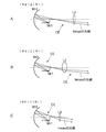
- (Constituent condition 6-1) 11 to 13 are schematic views for explaining the configuration condition 6.
- the first refractive optics system L1, the first reflecting surface Mr1, and the second reflecting surface Mr2 are referred to as the first optical system LL1. That is, from the incident surface F1 of the lens L11 to the second reflecting surface Mr2 becomes the first optical system LL1.
- the portion of the second refractive optics system L2 that acts on the edge side light beam is referred to as the second optical system LL2. That is, when the portion of the second refraction optical system L2 in which the edge-side ray CE travels is regarded as one optical system, the optical system becomes the second optical system LL2.
- the projection optical system 15 is configured such that the first optical system L1 concentrates the edge-side ray CE at a predetermined condensing position 35. Further, the projection optical system 15 is configured such that the light collecting position 35 coincides with the front focal position 36 of the second optical system LL2. That is, the projection optical system 15 is configured such that the first optical system LL2 concentrates the edge side ray CE at the front focal position 36 of the second optical system LL2.
- the front focal position 36 of the second optical system LL2 will be described with reference to FIG.
- the average angle ⁇ 1 is the average value of the angles at which the traveling directions of the edge-side light rays CE incident on the concave reflecting surface Mr3 (the incident direction on the concave reflecting surface Mr3) and the directions along the optical axis O intersect. ..
- the region on the final lens surface F5 of the second refractive optics system L2 where the edge-side ray CE is incident is defined as the edge-side incident region 37.
- the front focal position 36 of the second optical system LL2 is incident on the edge side of the final lens surface F5 along the direction intersecting the direction along the optical axis O at an average angle ⁇ 1. This is the focusing position when the parallel light beam 38 is incident on the region 37 from the opposite side.
- the optical path length from the image modulation element (liquid crystal panel P) to the condensing position 35 is the optical path length A.
- B the optical path length from the intermediate incident position 41 to the front focal length position 36.
- the optical path length B is a ray traveling from the intermediate incident position 41 to the front focal position 36 when the parallel ray 38 is incident on the edge side incident region 37 of the final lens surface F5 from the opposite side.
- C the optical path length from the illumination optical system 10 of the intermediate ray 40 to the intermediate incident position 41.
- the optical path length from the image modulation element (liquid crystal panel P) to the intermediate incident position 41 is the optical path length C.
- the projection optical system 15 is configured so as to satisfy the following relationship. (4) 0.8 ⁇ A + B
- the edge-side ray CE emitted from the second bending optical system L2 diverges and does not become a parallel ray.
- / C exceeds the lower limit specified in the conditional equation (4), the edge-side ray CE emitted from the second refractive optics system L2 is focused and does not become a parallel ray.
- the projection optical system 15 is configured so as to satisfy the conditional expression (4). That is, the projection optical system 15 is configured so that the light-collecting position 35 coincides with the front focal position 36. As a result, (Constituent condition 2) can be satisfied, and the uniformity of the brightness and the magnification of the edge side region of the projected image can be improved.
- a first intermediate image is formed between the dichroic prism PP included in the illumination optical system 10 and the first reflection surface Mr1. Further, a second intermediate image is formed between the first reflecting surface Mr1 and the second reflecting surface Mr2. Further, a third intermediate image is formed between the second refractive optics system L2 and the concave reflection surface Mr3. Then, an image is formed on the screen by the concave reflecting surface Mr3.
- the first optical system LL1 can be said to be an optical system on the front stage side with the second intermediate image as a boundary. Further, the second optical system LL2 can be said to be an optical system on the rear stage side with the second intermediate image as a boundary.
- the application of this technique is not limited to the case of forming such an intermediate image.
- the edge side light ray CE is emitted from the liquid crystal panel P along the optical axis O. Therefore, the condensing position 35 where the edge-side ray CE is focused by the first optical system LL1 can be said to be the rear focal position of the first optical system LL1. Therefore, in the present embodiment, with respect to (Constituent condition 6-1) and (Constituent condition 6-2), the condensing position 35 can be paraphrased as the posterior focal position of the first optical system LL1.
- the projection optical system 15 In constructing the projection optical system 15 according to the present technology, it is not always necessary that all the constituent conditions listed above are satisfied. If at least one of the above configuration conditions is satisfied, it can function as an embodiment of the projection optical system according to the present technology. Then, it becomes possible to realize a high-quality image display. Of course, all the constituent conditions may be satisfied. Alternatively, the projection optical system 15 may be configured so that any two or more configuration conditions are satisfied.
- each of the conditional expressions (1), (2) and (4) are not limited to the above-mentioned values.
- each value can be appropriately changed according to the configuration of the illumination optical system 10, the projection optical system 15, and the like.
- any value included in the above range may be selected as the lower limit value and the upper limit value, and may be set again as the optimum range.
- conditional expression (1) can be set in the following range. 0.01 ⁇
- conditional expression (2) can be set in the following range. 0.05 ⁇
- conditional expression (4) can be set in the following range. 0.7 ⁇
- the projection optical system 15 configured as described above will be briefly described with specific numerical examples.
- FIG. 14 is a table showing an example of parameters related to image projection.
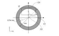
- FIG. 15 is a schematic diagram for explaining the parameters shown in FIG.
- the numerical aperture NA of the projection optical system 15 on the primary image plane side is 0.127.
- the horizontal and vertical lengths (H ⁇ VSp) of the image modulation element (liquid crystal panel P) are 15.6 mm and 8.7 mm.
- the center position (Chp) of the image modulation element is a position 5.6 mm above the optical axis O.
- the image circle (imc) on the primary image plane side is ⁇ 26.3 mm.
- the pixel light C1 shown in FIG. 5 and the like is emitted from the central pixel of the liquid crystal panel P (the same reference numeral is used for the pixel C1).
- Pixel light C2 is emitted from the pixel closest to the optical axis O in the center of the liquid crystal panel P (the same reference numeral is used as pixel C2).
- Pixel light C3 is emitted from the pixel farthest from the optical axis O in the center of the liquid crystal panel P (the same reference numeral is used as pixel C3).
- an image circle (0.74 ⁇ imc) having an image height of 74% is defined with respect to an image circle (imc) having a maximum image height.
- the light beam emitted from the region from the image circle with an image height of 74% to the image circle (imc) with the maximum image height (the region displayed in gray in the figure) is referred to as a high image height emission ray.
- the following constituent conditions can be mentioned for the high-image and high-emission light rays.
- the projection optical system 15 is configured such that high-image and high-emission light rays become parallel light rays and are incident on the concave reflection surface Mr3 (conditions corresponding to the configuration condition 2).
- the projection optical system 15 is configured such that high-image and high-emission rays are incident on the concave reflecting surface Mr3 at equal light intervals (conditions corresponding to the configuration condition 3).
- the condensing position 35 coincides with the front focal position 36 in the portion of the first optical system LL1 and the second refracting optical system L2 that acts on the high-image high-emission light beam (constituent condition). Conditions corresponding to 6-1).
- Conditional expression (4) is satisfied in the portion of the first optical system LL1 and the second refraction optical system L2 that acts on the high-image high-emission light rays (conditions corresponding to the constituent condition 6-2).
- the projection optical system 15 By configuring the projection optical system 15 so as to satisfy the constitutional conditions relating to these high-image and high-emission rays, the same effect as described above can be exhibited. That is, it is possible to improve the uniformity of the brightness and the magnification of the edge side region of the projected image, and it is possible to realize a high-quality image display.
- the high-image high-emission ray group and the edge-side ray group may be the same ray group or different ray groups.
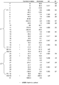
- FIG. 17 is lens data of the image display device.
- FIG. 17 shows data on the optical components (lens surface) and the curved screen S of 1-33 arranged from the primary image plane (P) side to the secondary image plane (S) side. ..
- the radius of curvature (mm) As the data of each optical component (lens surface), the radius of curvature (mm), the core thickness d (mm), the refractive index nd at the d line (587.56 nm), and the Abbe number ⁇ d at the d line are described.
- the radius of curvature (mm) is described.
- optical component having an aspherical surface follows the following formula.
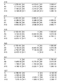
- FIG. 18 is a table showing an example of the aspherical coefficient of the optical component included in the projection optical system.
- FIG. 18 shows the aspherical coefficients for each of the aspherical optical components 19, 20, 21, 23, 24, and 33 marked with * in FIG. 17, respectively.
- the aspherical coefficient in the example corresponds to the above equation (Equation 1).
- the equation (Equation 1) corresponds to the function Z (h) representing the shape of the concave reflecting surface Mr3 according to the height of the light beam.
- the sag amount Z when the light ray height h is input is used as a parameter representing the shape of the concave reflecting surface Mr3 according to the light ray height.
- the "sag amount” is the distance between the plane and the point on the lens surface in the optical axis direction when a plane perpendicular to the optical axis is erected through the surface apex.
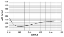
- FIG. 19 is a graph showing the relationship between the ray height h and ⁇ (h) / ⁇ (hmax).
- the light ray height h of the optical axis O is set to 0, the light ray height hmax is set to 1, and the calculation is performed after normalizing the light ray height h. From 0.9 to 1.00, the height of the light beam away from the optical axis O, ⁇ (h) / ⁇ (hmax) changes slowly. This means that the shape of the concave reflecting surface Mr3 changes slowly from the edge side region from (0.9 ⁇ hmax) to (hmax) in the light ray height.
- / ⁇ (hmax) in the conditional expression (1) is the value of the ray height 1.00 in the graph shown in FIG. 19 and the ray height 0. It is the difference from the value of .9.
- FIG. 20 is a table showing the numerical values of the parameters used in the above-mentioned conditional expressions (1), (2) and (4) in the present embodiment.
- / C 1.004 As a result, it can be seen that the conditional expressions (1), (2) and (4) are satisfied.
- the conditional expression (3) is also satisfied. Further, in the present embodiment, all the constituent conditions 1 to 6 are satisfied.
- the conditional expression (4) holds for the light rays emitted from the region from the image circle with the image height of 59% to the image circle (imc) with the maximum image height. Therefore, it is also possible to define the light beam as a high image high emission light ray.
- the shape of the concave reflecting surface Mr3 that reflects the image light toward the projectile is designed as described above. This makes it possible to realize high-quality image display.
- the concave reflection surface Mr3 allows at least a part of the light rays of the image light to be 90 degrees with the direction along the optical axis O as a reference in forming the projection optical system 15. It is reflected in the direction of intersection at the above angles. This makes it possible to support projection of an image on, for example, a curved screen S, and it is possible to realize high-quality image display.
- the image displayed on the flat screen and the image displayed on the curved screen have different shapes.
- the image displayed on the flat screen is a distorted image. Therefore, in order to properly display an image on a curved screen, it is necessary to perform an electrical correction process on the image signal.
- the amount of correction depends on the shape of the curved screen, but it is often large, and there is a possibility that the image quality of the image may be deteriorated.
- the image display device in order to display an image in a wide range of the curved screen, the image display device must be installed at a position away from the curved screen. As a result, the existence of the image display device becomes conspicuous for the user who views the image, and the immersive feeling in the content is impaired. In addition, since the area where the shadow of the user appears becomes large, the area where the user can move becomes small. As a result, it becomes difficult to provide an excellent viewing environment.
- the range that can be reflected by the concave reflecting surface Mr3 is designed to be as wide as 90 degrees or more with respect to the reference optical axis O.
- the range that can be reflected by the concave reflecting surface Mr3 is designed to be as wide as 90 degrees or more with respect to the reference optical axis O.
- FIG. 3 since it is possible to project an image from a position close to the curved screen S over a wide range of the curved screen S, the presence of the first and second image display devices 20a and 20b makes it possible to project the image.
- FIG. 21 and 22 are optical path diagrams showing a schematic configuration example of the projection optical system 215 according to the second embodiment.
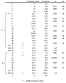
- FIG. 23 is lens data of the image display device.
- FIG. 24 is a table showing an example of the aspherical coefficient of the optical component included in the projection optical system.
- FIG. 25 is a graph showing the relationship between the ray height h and ⁇ (h) / ⁇ (hmax). The parameters related to image projection are the same as those in the first embodiment, and are the numerical values shown in FIG.
- the concave reflection surface Mr3 due to the concave reflection surface Mr3, at least a part of the light rays contained in the image light incident on the concave reflection surface Mr3 is directed along the optical axis O which is the reference axis and 90. It is reflected in the direction of intersection at an angle of more than a degree. This makes it possible to realize a high-quality image display corresponding to the curved screen S.
- FIG. 26 is a table showing the numerical values of the parameters used in the above-mentioned conditional expressions (1), (2) and (4) in the present embodiment.
- / C 1.003 As a result, it can be seen that the conditional expressions (1), (2) and (4) are satisfied.
- the conditional expression (3) is also satisfied. Further, in the projection optical system 215 according to the present embodiment, all the constituent conditions 1 to 6 are satisfied. As a result, it is possible to improve the uniformity of the brightness and the magnification of the edge side region of the projected image, and it is possible to realize a high-quality image display.
- conditional expression (4) holds for the light rays emitted from the region from the image circle with the image height of 59% to the image circle (imc) with the maximum image height. Therefore, it is also possible to define the light beam as a high image high emission light ray.
- FIG. 29 is a table showing an example of parameters related to image projection.
- FIG. 30 is lens data of the image display device.
- FIG. 31 is a table showing an example of the aspherical coefficient of the optical component included in the projection optical system.
- FIG. 32 is a graph showing the relationship between the ray height h and ⁇ (h) / ⁇ (hmax).
- the image light is projected toward the flat screen S'.
- the concave reflecting surface Mr3 of the projection optical system 315 reflects the light rays contained in the image light incident on the concave reflecting surface Mr3 in a direction intersecting the direction along the optical axis O at an angle of less than 90 degrees. This technique can also be applied to such an image display device.
- FIG. 33 is a table showing the numerical values of the parameters used in the above-mentioned conditional expressions (1), (2) and (4) in the present embodiment.
- / C 0.972 As a result, it can be seen that the conditional expressions (1), (2) and (4) are satisfied.
- the conditional expression (3) is also satisfied. Further, in the projection optical system 315 according to the present embodiment, all the constituent conditions 1 to 6 are satisfied. As a result, it is possible to improve the uniformity of the brightness and the magnification of the edge side region of the projected image, and it is possible to realize a high-quality image display.
- conditional expression (4) holds for a light ray whose reflection point reflected by the concave reflection surface Mr3 is included in a range larger than 0.82 ⁇ hmax. Therefore, it is also possible to define the light beam as an edge side light ray. Further, in the present embodiment, the conditional expression (4) holds for the light rays emitted from the region from the image circle with the image height of 71% to the image circle (imc) with the maximum image height. Therefore, it is also possible to define the light beam as a high image high emission light ray.
- FIG. 36 and 35 are optical path diagrams showing a schematic configuration example of the projection optical system 415 according to the fourth embodiment.
- FIG. 36 is a table showing an example of parameters related to image projection.
- FIG. 37 is lens data of the image display device.
- FIG. 38 is a table showing an example of the aspherical coefficient of the optical component included in the projection optical system.
- FIG. 39 is a graph showing the relationship between the ray height h and ⁇ (h) / ⁇ (hmax).
- the image light is projected toward the flat screen S'.
- the concave reflecting surface Mr3 of the projection optical system 415 reflects light rays contained in the image light incident on the concave reflecting surface Mr3 in a direction intersecting the direction along the optical axis O at an angle of less than 90 degrees.
- FIG. 40 is a table showing the numerical values of the parameters used in the above-mentioned conditional expressions (1), (2) and (4) in the present embodiment.
- / C 1.0388 As a result, it can be seen that the conditional expressions (1), (2) and (4) are satisfied.
- the conditional expression (3) is also satisfied. Further, in the projection optical system 315 according to the present embodiment, all the constituent conditions 1 to 6 are satisfied. As a result, it is possible to improve the uniformity of the brightness and the magnification of the edge side region of the projected image, and it is possible to realize a high-quality image display.
- conditional expression (4) holds for a light ray whose reflection point reflected by the concave reflection surface Mr3 is included in a range larger than 0.78 ⁇ hmax. Therefore, it is also possible to define the light beam as an edge side light ray.
- FIG. 41 and 42 are schematic views showing a configuration example of an image display system according to another embodiment.
- a curved screen S having a dome shape is used.
- the dome shape is not limited to the hemispherical shape, and includes any shape that can cover the upper part over a circumference of 360 degrees.
- the curved screen S having a dome shape can be said to be a dome screen.
- first and second image display devices 520a and 520b are installed below the dome-shaped curved screen S so as to face each other in the left-right direction.
- the first and second image display devices 520a and 520b are installed so that the first and second images 521a and 521b can be projected upward.
- the first and second images 521a and 521b are projected so as to overlap each other along the long side direction (left-right direction). Therefore, an overlapping region 522 in which the first and second images 521a and 521b overlap each other is generated at the apex portion of the curved screen S.
- the stitching process is executed with the overlapping area 522 as a reference, and one large image is displayed.
- the first to third image display devices 620a to 620b are arranged at equal intervals along the circumference below the dome-shaped curved screen S.
- the first to third image display devices 620a to 620c are installed so as to be able to project the first to third images 621a to 621c upward.
- FIG. 42B as the first to third images 621a to 621c, image light for forming a rectangular image is projected.
- each of the first to third images 621a to 621c is schematically shown in a rectangular shape, but the shape displayed on the curved screen S is different from the rectangular shape.
- the first to third images 621a and 621b are projected so as to overlap each other at positions symmetrical with respect to the vertices of the curved screen S. Then, the stitching process is executed in the overlapping areas 622a to 622c, and one large-sized image is displayed.
- the image display devices according to the present technology described above as the first to third image display devices 620a to 620c, it is possible to realize high-quality image display corresponding to the dome shape, and to provide an excellent viewing environment. It will be possible to provide. As described above, this technique can be applied even when three or more image display devices are used.
- a free curved surface having no axis of rotational symmetry may be used as the concave reflecting surface that reflects the image light on the screen.
- the optical axis of the concave reflecting surface (for example, the axis passing through the center of the optical surface) is aligned with the reference axis that serves as a reference in forming the lens system. This makes it possible to exert the same effect as described above.
- a free curved surface having no axis of rotational symmetry may be used for the first reflecting surface and the second reflecting surface. That is, at least one of the concave reflecting surface, the first reflecting surface, or the second reflecting surface may be a free curved surface having no axis of rotational symmetry.
- the projectile is not limited to the curved screen.
- This technology can be applied to the display of images on arbitrary projectiles such as walls of tables and buildings. In particular, it is possible to realize a high-quality image display corresponding to a projectile having a curved surface shape.
- expressions using "more” such as “greater than A” and “less than A” include both the concept including the case equivalent to A and the concept not including the case equivalent to A. It is an expression that includes the concept. For example, “greater than A” is not limited to the case where the equivalent of A is not included, and “greater than or equal to A” is also included. Further, “less than A” is not limited to “less than A” and includes “less than or equal to A”. When implementing this technique, specific settings and the like may be appropriately adopted from the concepts included in “greater than A” and “less than A” so that the effects described above can be exhibited.
- this technology can also adopt the following configurations.
- Light source and An image generator that modulates the light emitted from the light source to generate image light A lens system configured with reference to the reference axis at the position where the generated image light is incident and having a positive refractive power as a whole. It is provided with a projection optical system configured with the reference axis as a reference and having a concave reflecting surface that reflects the image light emitted from the lens system toward the object to be projected.
- the height of the light beam from the reference axis is h
- the angle of the tangent of the function Z (h) representing the shape of the concave reflecting surface corresponding to the light ray height h with respect to the height direction of the optical axis is ⁇ (h).
- the amount of change in the angle ⁇ (h) at the ray height h is ⁇ (h)
- hmax be the light beam height h of the reflection point farthest from the reference axis of the concave reflection surface that reflects the image light. 0 ⁇
- the ⁇ (h) is an image display device of ⁇ (h) ⁇ (0.98 ⁇ h).
- the projection optical system is an image display device configured so that the traveling directions of the edge-side light rays incident on the concave reflection surface are parallel to each other.
- the projection optical system is an image display device configured so that the distance between the edge-side light rays incident on the concave reflection surface is equal.
- the lens system is A first folding optics system that has a positive refractive power as a whole and refracts the generated image light.
- the power of the first reflecting surface is ⁇ 1, Assuming that the power of the second reflecting surface is ⁇ 2, 0.1 ⁇
- the image display device that is configured to satisfy the relationship.
- the image display device (7)
- the first refractive optics system, the first reflective surface, and the second reflective surface are the first optical system. Assuming that the portion of the second refractive optics system that acts on the edge side light beam is the second optical system, The first optical system condenses the edge-side light beam at a predetermined condensing position.
- the predetermined focusing position is an image display device that coincides with the front focal position of the second optical system.
- the image display device according to (7).
- a ray having an intermediate value at the height of the reflection point reflected by the concave reflecting surface is referred to as an intermediate ray.
- the position of the intermediate light beam incident on the final lens surface of the second refractive optics is defined as the intermediate incident position.
- the optical path length from the image generation unit of the intermediate ray to the predetermined condensing position is A.
- the optical path length from the intermediate incident position to the front focal length is B, Let C be the optical path length from the image generation unit of the intermediate ray to the intermediate incident position. 0.8 ⁇ A + B
- An image display device that is configured to satisfy the relationship. (9) The image display device according to (8).
- the average angle is the average value of the angles at which the traveling directions of the edge-side rays incident on the concave reflecting surface intersect with the directions along the reference axis. Assuming that the region where the edge-side light rays are incident on the final lens surface of the second refractive optics is the edge-side incident region. The front focal position of the second optical system is parallel to the edge-side incident region of the final lens surface from the opposite side along a direction intersecting the direction along the reference axis at the average angle.
- An image display device that is the focusing position when a light beam is incident. (10) The image display device according to (9).
- the optical path length B is an image display which is an optical path length of a light ray traveling from the intermediate incident position to the rear focal position when a parallel light ray is incident on the edge side incident region of the final lens surface from the opposite side.
- Device. (11) The image display device according to any one of (1) to (10).
- the concave reflecting surface is an image display device that reflects at least a part of light rays contained in the image light incident on the concave reflecting surface in a direction that intersects a direction along the reference axis at an angle of 90 degrees or more.
- the projection optical system has a first optical component in which a part of the main surface is configured as the first reflecting surface and a transmission surface is formed in another region of the main surface.
- the transmission surface of the first optical component is an image display device that functions as the second refractive optics system.
- the projection optical system has a second optical component in which a part of the main surface is configured as the second reflecting surface and a transmission surface is formed in another region of the main surface.
- the transmission surface of the second optical component is an image display device that functions as the first refractive optics system.
- the reference axis is an image display device that extends the optical axis of the lens closest to the image generation unit included in the lens system.
- the projection optical system is an image display device configured so that the optical axes of all the optical components included in the projection optical system coincide with a predetermined reference axis.
- the concave reflective surface is configured so that the axis of rotational symmetry coincides with the reference axis.
- Each of the first reflecting surface and the second reflecting surface is a concave reflecting surface, and is an image display device configured so that the axis of rotational symmetry coincides with the reference axis.
- Each of the concave reflecting surface, the first reflecting surface, and the second reflecting surface is configured so that the optical axis coincides with the reference axis.
- An image display device in which at least one of the concave reflecting surface, the first reflecting surface, or the second reflecting surface is a free curved surface having no axis of rotational symmetry.
- the projectile is an image display device having a flat screen or a curved screen.
- the projectile is an image display device which is a screen having a dome shape.
- It is a projection optical system that projects image light generated by modulating the light emitted from a light source.
- a lens system configured with reference to the reference axis at the position where the generated image light is incident and having a positive refractive power as a whole.
- the reference axis includes a concave reflecting surface that reflects the image light emitted from the lens system toward the projectile.
- the height of the light beam from the reference axis is h
- the angle of the tangent of the function Z (h) representing the shape of the concave reflecting surface corresponding to the light ray height h with respect to the height direction of the optical axis is ⁇ (h).
- the amount of change in the angle ⁇ (h) at the ray height h is ⁇ (h)
- a projection optical system that is configured to satisfy the relationship of.
Landscapes
- Physics & Mathematics (AREA)
- General Physics & Mathematics (AREA)
- Optics & Photonics (AREA)
- Engineering & Computer Science (AREA)
- Multimedia (AREA)
- Signal Processing (AREA)
- Lenses (AREA)
- Projection Apparatus (AREA)
Priority Applications (4)
| Application Number | Priority Date | Filing Date | Title |
|---|---|---|---|
| DE112021002934.7T DE112021002934T5 (de) | 2020-05-27 | 2021-05-17 | Bildanzeigeeinrichtung und optisches projektionssystem |
| CN202180036314.5A CN115668026A (zh) | 2020-05-27 | 2021-05-17 | 图像显示装置和投影光学系统 |
| US17/998,973 US12481208B2 (en) | 2020-05-27 | 2021-05-17 | Image display apparatus and projection optical system |
| JP2022526902A JP7697461B2 (ja) | 2020-05-27 | 2021-05-17 | 画像表示装置及び投射光学系 |
Applications Claiming Priority (2)
| Application Number | Priority Date | Filing Date | Title |
|---|---|---|---|
| JP2020091942 | 2020-05-27 | ||
| JP2020-091942 | 2020-05-27 |
Publications (1)
| Publication Number | Publication Date |
|---|---|
| WO2021241297A1 true WO2021241297A1 (ja) | 2021-12-02 |
Family
ID=78744617
Family Applications (1)
| Application Number | Title | Priority Date | Filing Date |
|---|---|---|---|
| PCT/JP2021/018550 Ceased WO2021241297A1 (ja) | 2020-05-27 | 2021-05-17 | 画像表示装置及び投射光学系 |
Country Status (6)
| Country | Link |
|---|---|
| US (1) | US12481208B2 (https=) |
| JP (1) | JP7697461B2 (https=) |
| CN (1) | CN115668026A (https=) |
| DE (1) | DE112021002934T5 (https=) |
| TW (1) | TW202204969A (https=) |
| WO (1) | WO2021241297A1 (https=) |
Cited By (2)
| Publication number | Priority date | Publication date | Assignee | Title |
|---|---|---|---|---|
| CN116482924A (zh) * | 2023-04-20 | 2023-07-25 | 蔚来汽车科技(安徽)有限公司 | 激光投影组件、激光投影装置及其控制方法 |
| WO2025220275A1 (ja) * | 2024-04-18 | 2025-10-23 | パナソニックIpマネジメント株式会社 | 光学系、画像投写装置および撮像装置 |
Citations (15)
| Publication number | Priority date | Publication date | Assignee | Title |
|---|---|---|---|---|
| WO2006043666A1 (ja) * | 2004-10-21 | 2006-04-27 | Sony Corporation | 投射光学系及び投射型画像表示装置 |
| WO2009107744A1 (ja) * | 2008-02-29 | 2009-09-03 | 国立大学法人東北大学 | 投影光学系および投影装置 |
| US20110267687A1 (en) * | 2010-04-29 | 2011-11-03 | Samsung Electronics Co., Ltd. | Optical system and image projecting apparatus using the same |
| US20140002802A1 (en) * | 2012-06-27 | 2014-01-02 | Young Optics Inc. | Projection apparatus and projection lens thereof |
| WO2014103324A1 (ja) * | 2012-12-28 | 2014-07-03 | 日東光学株式会社 | 投射光学系およびプロジェクタ装置 |
| JP2015031912A (ja) * | 2013-08-06 | 2015-02-16 | 三星電子株式会社Samsung Electronics Co.,Ltd. | 投射光学系及び画像投射装置 |
| WO2016017434A1 (ja) * | 2014-07-28 | 2016-02-04 | コニカミノルタ株式会社 | 投影光学系及び投影装置 |
| WO2016068269A1 (ja) * | 2014-10-31 | 2016-05-06 | 日東光学株式会社 | 投射光学系およびプロジェクタ装置 |
| WO2017188449A1 (ja) * | 2016-04-28 | 2017-11-02 | 株式会社nittoh | 特性の異なる領域を含むレンズを有する光学システム |
| WO2018042865A1 (ja) * | 2016-08-30 | 2018-03-08 | ソニー株式会社 | 画像表示装置及び投射光学系 |
| WO2018117210A1 (ja) * | 2016-12-21 | 2018-06-28 | 株式会社nittoh | 投射光学系およびプロジェクタ |
| WO2019012795A1 (ja) * | 2017-07-10 | 2019-01-17 | ソニー株式会社 | 画像表示装置及び投射光学系 |
| WO2019146425A1 (ja) * | 2018-01-25 | 2019-08-01 | ソニー株式会社 | 画像処理装置、画像処理方法、プログラム、および投影システム |
| WO2019216017A1 (ja) * | 2018-05-10 | 2019-11-14 | ソニー株式会社 | 画像表示装置、投射光学系、及び画像表示システム |
| WO2020004099A1 (ja) * | 2018-06-29 | 2020-01-02 | ソニー株式会社 | 画像表示装置及び投射光学系 |
Family Cites Families (9)
| Publication number | Priority date | Publication date | Assignee | Title |
|---|---|---|---|---|
| US6511184B2 (en) * | 2000-04-05 | 2003-01-28 | Matsushita Electric Industrial Co., Ltd. | Color image display apparatus |
| CN100462774C (zh) * | 2005-08-22 | 2009-02-18 | 佳能株式会社 | 光学扫描系统和利用该系统的图像形成设备 |
| CN100541114C (zh) * | 2007-07-24 | 2009-09-16 | 哈尔滨工程大学 | 双曲面反射镜的多维全场光学校验装置 |
| JP5365155B2 (ja) | 2008-11-21 | 2013-12-11 | ソニー株式会社 | 投射型画像表示装置および投射光学系 |
| WO2013080953A1 (ja) | 2011-12-01 | 2013-06-06 | 三菱電機株式会社 | 投写光学系および投写型画像表示装置 |
| CN204360020U (zh) * | 2015-01-19 | 2015-05-27 | 上海芯天电子有限公司 | 一种消除汽车平视显示器投影图像重影的装置 |
| EP3420601B1 (en) * | 2016-02-26 | 2023-08-02 | Magic Leap, Inc. | Optical system |
| WO2018066501A1 (ja) | 2016-10-03 | 2018-04-12 | 株式会社クラレ | 拡散板及び投写式画像表示装置 |
| CN110039407B (zh) * | 2019-05-28 | 2020-07-07 | 长光卫星技术有限公司 | 一种有效减小反射镜光学加工边缘效应的快速抛光方法 |
-
2021
- 2021-04-13 TW TW110113224A patent/TW202204969A/zh unknown
- 2021-05-17 DE DE112021002934.7T patent/DE112021002934T5/de not_active Withdrawn
- 2021-05-17 US US17/998,973 patent/US12481208B2/en active Active
- 2021-05-17 CN CN202180036314.5A patent/CN115668026A/zh active Pending
- 2021-05-17 WO PCT/JP2021/018550 patent/WO2021241297A1/ja not_active Ceased
- 2021-05-17 JP JP2022526902A patent/JP7697461B2/ja active Active
Patent Citations (15)
| Publication number | Priority date | Publication date | Assignee | Title |
|---|---|---|---|---|
| WO2006043666A1 (ja) * | 2004-10-21 | 2006-04-27 | Sony Corporation | 投射光学系及び投射型画像表示装置 |
| WO2009107744A1 (ja) * | 2008-02-29 | 2009-09-03 | 国立大学法人東北大学 | 投影光学系および投影装置 |
| US20110267687A1 (en) * | 2010-04-29 | 2011-11-03 | Samsung Electronics Co., Ltd. | Optical system and image projecting apparatus using the same |
| US20140002802A1 (en) * | 2012-06-27 | 2014-01-02 | Young Optics Inc. | Projection apparatus and projection lens thereof |
| WO2014103324A1 (ja) * | 2012-12-28 | 2014-07-03 | 日東光学株式会社 | 投射光学系およびプロジェクタ装置 |
| JP2015031912A (ja) * | 2013-08-06 | 2015-02-16 | 三星電子株式会社Samsung Electronics Co.,Ltd. | 投射光学系及び画像投射装置 |
| WO2016017434A1 (ja) * | 2014-07-28 | 2016-02-04 | コニカミノルタ株式会社 | 投影光学系及び投影装置 |
| WO2016068269A1 (ja) * | 2014-10-31 | 2016-05-06 | 日東光学株式会社 | 投射光学系およびプロジェクタ装置 |
| WO2017188449A1 (ja) * | 2016-04-28 | 2017-11-02 | 株式会社nittoh | 特性の異なる領域を含むレンズを有する光学システム |
| WO2018042865A1 (ja) * | 2016-08-30 | 2018-03-08 | ソニー株式会社 | 画像表示装置及び投射光学系 |
| WO2018117210A1 (ja) * | 2016-12-21 | 2018-06-28 | 株式会社nittoh | 投射光学系およびプロジェクタ |
| WO2019012795A1 (ja) * | 2017-07-10 | 2019-01-17 | ソニー株式会社 | 画像表示装置及び投射光学系 |
| WO2019146425A1 (ja) * | 2018-01-25 | 2019-08-01 | ソニー株式会社 | 画像処理装置、画像処理方法、プログラム、および投影システム |
| WO2019216017A1 (ja) * | 2018-05-10 | 2019-11-14 | ソニー株式会社 | 画像表示装置、投射光学系、及び画像表示システム |
| WO2020004099A1 (ja) * | 2018-06-29 | 2020-01-02 | ソニー株式会社 | 画像表示装置及び投射光学系 |
Cited By (2)
| Publication number | Priority date | Publication date | Assignee | Title |
|---|---|---|---|---|
| CN116482924A (zh) * | 2023-04-20 | 2023-07-25 | 蔚来汽车科技(安徽)有限公司 | 激光投影组件、激光投影装置及其控制方法 |
| WO2025220275A1 (ja) * | 2024-04-18 | 2025-10-23 | パナソニックIpマネジメント株式会社 | 光学系、画像投写装置および撮像装置 |
Also Published As
| Publication number | Publication date |
|---|---|
| US12481208B2 (en) | 2025-11-25 |
| JPWO2021241297A1 (https=) | 2021-12-02 |
| US20230176463A1 (en) | 2023-06-08 |
| JP7697461B2 (ja) | 2025-06-24 |
| CN115668026A (zh) | 2023-01-31 |
| TW202204969A (zh) | 2022-02-01 |
| DE112021002934T5 (de) | 2023-03-30 |
Similar Documents
| Publication | Publication Date | Title |
|---|---|---|
| JP7099460B2 (ja) | 画像表示装置及び投射光学系 | |
| JP5484098B2 (ja) | 投写光学系及び画像表示装置 | |
| JP6368988B2 (ja) | 投射光学系および画像表示装置 | |
| JP7243723B2 (ja) | 画像表示装置及び投射光学系 | |
| JP7207405B2 (ja) | 画像表示装置、投射光学系、及び画像表示システム | |
| JP7697461B2 (ja) | 画像表示装置及び投射光学系 | |
| JP7318665B2 (ja) | 画像表示装置及び投射光学系 | |
| JP7800566B2 (ja) | 画像表示装置、画像表示システム、及び投射光学系 | |
| JP6803764B2 (ja) | 投射光学系および画像表示装置 |
Legal Events
| Date | Code | Title | Description |
|---|---|---|---|
| 121 | Ep: the epo has been informed by wipo that ep was designated in this application |
Ref document number: 21811995 Country of ref document: EP Kind code of ref document: A1 |
|
| ENP | Entry into the national phase |
Ref document number: 2022526902 Country of ref document: JP Kind code of ref document: A |
|
| 122 | Ep: pct application non-entry in european phase |
Ref document number: 21811995 Country of ref document: EP Kind code of ref document: A1 |
|
| WWG | Wipo information: grant in national office |
Ref document number: 17998973 Country of ref document: US |