WO2021240740A1 - ばね用鋼線、ばね及びそれらの製造方法 - Google Patents
ばね用鋼線、ばね及びそれらの製造方法 Download PDFInfo
- Publication number
- WO2021240740A1 WO2021240740A1 PCT/JP2020/021159 JP2020021159W WO2021240740A1 WO 2021240740 A1 WO2021240740 A1 WO 2021240740A1 JP 2020021159 W JP2020021159 W JP 2020021159W WO 2021240740 A1 WO2021240740 A1 WO 2021240740A1
- Authority
- WO
- WIPO (PCT)
- Prior art keywords
- spring
- tempering
- less
- steel wire
- content
- Prior art date
- Legal status (The legal status is an assumption and is not a legal conclusion. Google has not performed a legal analysis and makes no representation as to the accuracy of the status listed.)
- Ceased
Links
Images




Classifications
-
- C—CHEMISTRY; METALLURGY
- C21—METALLURGY OF IRON
- C21D—MODIFYING THE PHYSICAL STRUCTURE OF FERROUS METALS; GENERAL DEVICES FOR HEAT TREATMENT OF FERROUS OR NON-FERROUS METALS OR ALLOYS; MAKING METAL MALLEABLE, e.g. BY DECARBURISATION OR TEMPERING
- C21D9/00—Heat treatment, e.g. annealing, hardening, quenching or tempering, adapted for particular articles; Furnaces therefor
- C21D9/02—Heat treatment, e.g. annealing, hardening, quenching or tempering, adapted for particular articles; Furnaces therefor for springs
-
- C—CHEMISTRY; METALLURGY
- C21—METALLURGY OF IRON
- C21D—MODIFYING THE PHYSICAL STRUCTURE OF FERROUS METALS; GENERAL DEVICES FOR HEAT TREATMENT OF FERROUS OR NON-FERROUS METALS OR ALLOYS; MAKING METAL MALLEABLE, e.g. BY DECARBURISATION OR TEMPERING
- C21D9/00—Heat treatment, e.g. annealing, hardening, quenching or tempering, adapted for particular articles; Furnaces therefor
- C21D9/52—Heat treatment, e.g. annealing, hardening, quenching or tempering, adapted for particular articles; Furnaces therefor for wires; for strips ; for rods of unlimited length
-
- C—CHEMISTRY; METALLURGY
- C22—METALLURGY; FERROUS OR NON-FERROUS ALLOYS; TREATMENT OF ALLOYS OR NON-FERROUS METALS
- C22C—ALLOYS
- C22C38/00—Ferrous alloys, e.g. steel alloys
-
- C—CHEMISTRY; METALLURGY
- C22—METALLURGY; FERROUS OR NON-FERROUS ALLOYS; TREATMENT OF ALLOYS OR NON-FERROUS METALS
- C22C—ALLOYS
- C22C38/00—Ferrous alloys, e.g. steel alloys
- C22C38/18—Ferrous alloys, e.g. steel alloys containing chromium
- C22C38/34—Ferrous alloys, e.g. steel alloys containing chromium with more than 1.5% by weight of silicon
Definitions
- the present invention relates to steel wires for springs, springs, and methods for manufacturing them, which are suitable for being applied to suspension springs of automobiles and the like.
- Pattern 1 is a step in which a spring wire is drawn out to a desired wire diameter in a straight line state and then quenched and tempered to form a spring steel wire, which is coldly processed into a spring shape.
- Pattern 2 is a step of cold-working a spring wire into a spring shape and then quenching and tempering.
- Pattern 3 is a step in which a wire for a spring is hot-processed into a spring shape in a state of being heated to 850 to 1000 ° C., and then quenched and tempered.
- Non-Patent Documents 1 to 3 As a means for improving the corrosion fatigue characteristics of springs, techniques for adjusting the components of springs and steel wires for springs to suppress corrosion pits have been reported (for example, Non-Patent Documents 1 to 3).
- Low alloy steels such as those applied to suspension springs for automobiles, it is difficult to sufficiently improve the corrosion fatigue characteristics so as to suppress the occurrence of corrosion and pitting corrosion by adjusting the alloying elements. Is. Therefore, in order to improve the corrosion fatigue characteristics of the spring, it is considered effective to improve the mechanical properties of the steel material, specifically, the tensile strength, the yield ratio, and the toughness.
- Non-Patent Document 4 A method for analyzing the precipitation state of iron carbide in the tempering process of spring steel by using differential scanning calorimetry (DSC) has been reported (Non-Patent Document 4). A method for optimizing the tempering conditions has been proposed by utilizing this method and evaluating the iron carbide precipitation state at the time of tempering of spring steel and spring by the DSC exothermic peak (Patent Document 1).
- Non-Patent Document 4 only the temperature at the apex of the exothermic peak is focused on. Since the shape of the peak curve, especially the peak width and position, varies depending on the amount of carbon and the amount of alloy added, the evaluation method focusing only on the temperature of the apex of the exothermic peak is insufficient as an evaluation method for the state of precipitation of fine iron carbides. Was found.
- An object of the present invention is to solve the above problems and to provide high-strength and high-toughness springs and steel wires for springs, which are suitable for suspension springs of automobiles, and a method for manufacturing them.
- the gist of the present invention is as follows.
- the steel wire for a spring according to one aspect of the present invention has a mass% of C: more than 0.50% and 0.60% or less, Si: 1.00 to 3.00%, Mn: as chemical components. 0.10 to 1.50%, Cr: 0.15 to 1.20%, Al: 0.050% or less, P: 0.015% or less, S: 0.015% or less, Ti: 0.010 to It contains 0.100%, B: 0.0010 to 0.0060%, and N: 0.0070% or less, the balance is composed of Fe and impurities, and the contents of Ti and N satisfy Formula 1.
- the metallographic structure at equidistant points from both the center and the surface is the tempered martensite structure, with a temperature range of 50 ° C to 600 ° C at 0.25 ° C / s.
- the area of the region of 450 ° C. or lower in the exothermic reaction peak obtained by raising the temperature and measuring the differential scanning calorific value is 30% or less of the total peak area of the exothermic reaction peak.
- the spring steel wire according to (1) above is further, in mass%, as the chemical components, Mo: 0 to 1.00%, Ni: 0 to 1.00%, Cu: 0-1. It may contain one or more of .00% Nb: 0 to 0.100% and V: 0 to 0.50% Sb: 0 to 0.050%.
- the spring according to another aspect of the present invention is a spring having the chemical component according to the above (1) or (2), and has a temperature range of 50 ° C to 600 ° C at 0.25 ° C / s. The area of the region of 450 ° C.
- the method for manufacturing a steel wire for a spring according to another aspect of the present invention is the method for manufacturing a steel wire for a spring according to the above (1) or (2), and the above (1) or (2).
- the present invention comprises a step of tempering under the condition that the Cr content C% [mass%] satisfies the formula 2.
- the method for manufacturing a spring according to another aspect of the present invention is the method for manufacturing a spring according to the above (3), wherein a wire rod composed of the chemical component according to the above (1) or (2) is used.
- the method for manufacturing a spring according to another aspect of the present invention is the method for manufacturing a spring according to the above (3), wherein a wire rod composed of the chemical component according to the above (1) or (2) is used.
- the present invention comprises a step of performing a tempering treatment under the conditions that the C% [mass%] and the Cr content C% [mass%] satisfy the formula 2. 58000 ⁇ (T + 700 ⁇ [C%] + 50 ⁇ [Cr%]) ⁇ (51.7 + log) ⁇ 62000 ... (Equation 2) (7)
- the method for manufacturing a spring according to another aspect of the present invention includes a step of performing spring processing on the steel wire for spring according to the above (1) or (2).
- the steel wire for spring according to this embodiment has a mass% of C: more than 0.50% and 0.60% or less, Si: 1.00 to 3.00%, Mn: 0.10 to 1 as chemical components. .50%, Cr: 0.15 to 1.20%, Al: 0.050% or less, P: 0.015% or less, S: 0.015% or less, Ti: 0.010 to 0.100%, B: 0.0010 to 0.0060%, N: 0.0070% or less, the balance was composed of Fe and impurities, the Ti and N contents satisfied the formula A, and the cells were cut perpendicularly in the longitudinal direction.
- the metallographic structure at points equidistant from both the center and the surface is tempered martensite, and the temperature range from 50 ° C to 600 ° C is heated at 0.25 ° C / s to measure the differential scanning heat.
- the area 4 of the region of 450 ° C. or lower among the peaks of the exothermic reaction obtained by the above is 30% or less of the total peak area 3 of the peaks of the exothermic reaction.
- the spring according to the present embodiment has the same chemical composition as the steel wire for spring according to the present embodiment, and the temperature range from 50 ° C. to 600 ° C. is raised at 0.25 ° C./s for differential scanning.
- the area of the region of 450 ° C. or lower among the peaks of the exothermic reaction obtained by measuring the calorific value is 30% or less of the total peak area of the peaks of the exothermic reaction.
- the manufacturing method of the spring according to the present embodiment is not particularly limited as long as these requirements are satisfied.
- the steel wire for spring is obtained by cold working into a spring shape, and the wire is molded into a spring shape by cold working or hot working, and then quenching treatment and tempering treatment are performed. What is obtained is shown as a suitable example of the spring according to this embodiment.
- the present inventors have a high-strength suspension spring, specifically, a tensile strength of 2000 MPa or more (if the spring shape is formed and the tensile strength cannot be measured, the Vickers hardness measured at a load of 300 gf is 573 HV or more).
- a high-strength suspension spring specifically, a tensile strength of 2000 MPa or more (if the spring shape is formed and the tensile strength cannot be measured, the Vickers hardness measured at a load of 300 gf is 573 HV or more).
- (I) In the case of suspended spring steel having high strength (tensile strength of 2000 MPa or more), if the toughness of the steel material is low, grain boundary fracture surfaces may appear on the fatigue fracture surface, and the growth rate of fatigue cracks becomes particularly high. That is, if the toughness of the steel material is improved, the fatigue strength of the spring can be increased.
- the “steel material” means both the steel constituting the spring steel wire according to the present embodiment and the steel constituting the spring according to the present embodiment.
- the DSC raises the temperature of the sample to cause phase transformation and iron carbide precipitation in the sample, and detects heat generation and endothermic at this time. Based on the DSC curve obtained thereby, the phase state and the iron carbide state in the sample before raising the temperature of the sample can be evaluated.
- the measurement by DSC is performed in accordance with JIS K 0129: 2005. Detailed measurement conditions will be described later.
- the peak is defined as the portion of the DSC curve from when the curve leaves the baseline to when it returns to the baseline again.
- the baseline is defined as the DSC curve in the temperature range where the test piece does not change. These terms are defined in accordance with JIS K 0129: 2005.
- the peak area is defined as the area surrounded by the peak and the baseline.
- FIGS. 1 and 2 An example of the DSC curve is shown in FIGS. 1 and 2.
- FIG. 1 is a DSC curve that does not satisfy the above requirements, that is, a DSC curve in which the area of the exothermic reaction peak in the region of 450 ° C. or lower is more than 30% of the total peak area of the exothermic reaction peak.
- FIG. 2 is a DSC curve that satisfies the above requirements, that is, a DSC curve in which the area of the exothermic reaction peak in the region of 450 ° C. or lower is 30% or less of the total peak area of the exothermic reaction peak.
- the structure of the as-quenched steel material is mainly martensite at the stage before DSC measurement, and C is solid-solved in this martensite.
- C is precipitated from martensite in the form of fine iron carbide, that is, ⁇ carbide. do. It is considered that this precipitation reaction is detected as peak 1 in FIG.
- the DSC measurement is continued and the temperature of the sample is further raised, the fine iron carbide transitions to the coarse ⁇ carbide. It is considered that this transition reaction is detected as peak 1 in FIG.
- Peak 1 is detected.
- a DSC curve as shown in FIG. 2 is obtained. Be done.
- the area 4 of the region of 450 ° C. or lower of the exothermic reaction peak is 30% or less of the total peak area 3 of the exothermic reaction peak. That is, in the DSC curve of the steel material obtained by the manufacturing method of tempering under predetermined conditions, the exothermic reaction (corresponding to peak 2 in FIG. 1) due to the transition of the fine iron carbide to the coarse ⁇ carbide by DSC measurement.
- the magnitude of the exothermic reaction (corresponding to peak 1 in FIG. 1) in which fine iron carbide is precipitated by DSC measurement is extremely small with respect to the magnitude.
- the structure of the steel material showing the DSC curve as shown in FIG. 2 is mainly tempered martensite at the stage before DSC measurement, and finer ⁇ -carbide is precipitated.
- fine iron carbides are sufficiently precipitated, there is no room for further fine iron carbides to precipitate, so that even if this is subjected to DSC measurement, the precipitation reaction of fine iron carbides does not occur. Therefore, it is considered that heat generation (corresponding to peak 1 in FIG. 1) due to precipitation of fine iron carbide hardly occurs in the DSC measurement of such a steel material.
- the steel material exhibiting the DSC curve as shown in FIG. 2 has extremely good toughness. It is presumed that this is because, as will be described later, in the steel material exhibiting the DSC curve as shown in FIG. 2, fine ⁇ -carbide is precipitated, and this fine iron carbide contributes to the improvement of toughness. NS.
- the steel material in which both peak 1 and peak 2 are observed in the DSC curve has a low yield ratio and inferior settling characteristics. It is presumed that this is because the precipitation of fine iron carbide is insufficient.
- C More than 0.50% and less than 0.60% C is an element necessary to obtain high strength. Therefore, it is necessary to contain more than 0.50% of C. On the other hand, if C of more than 0.60% is contained, the toughness is lowered. Further, if C is excessively contained, the tempering temperature for obtaining the desired strength rises, the amount of cementite ( ⁇ ) produced increases, and it is considered that both high strength and high toughness cannot be achieved at the same time. Therefore, the upper limit of the C content is set to 0.60%. A suitable upper limit for the C content is 0.58%, 0.57%, 0.56%, or 0.55%. A suitable lower limit for the C content is 0.51%, 0.52%, 0.53%, or 0.54%.
- Si 1.00 to 3.00%
- Si is an element effective for strengthening steel and improving the settling property of springs, and also improves temper softening resistance. In order to obtain this effect, it is necessary to contain 1.00% or more of Si. On the other hand, if Si is contained in an amount of more than 3.00%, decarburization during wire rolling or heat treatment is promoted. Therefore, it is necessary to set the upper limit of the amount of Si to 3.00%.
- a suitable lower limit for the amount of Si is 1.10%, 1.35%, or 1.50%.
- a suitable upper limit for the amount of Si is 2.80% or 2.50%.
- Mn 0.10 to 1.50%
- Mn is an element effective for improving tensile strength. In order to obtain this effect, it is necessary to contain Mn in an amount of 0.10% or more. On the other hand, if Mn is contained in an amount of more than 1.50%, central segregation during casting is promoted and toughness is lowered. Therefore, the Mn content needs to be in the range of 0.10 to 1.50%.
- the preferable lower limit of the Mn content is 0.15% or 0.25%.
- a suitable upper limit for the Mn content is 1.45%, 1.20%, or 1.00%.
- Cr 0.15 to 1.20% Cr has the effect of refining iron carbide and increasing its strength. In order to obtain this effect, it is necessary to contain Cr in an amount of 0.15% or more. On the other hand, if Cr is contained in an amount of more than 1.20%, central segregation during casting is promoted and the toughness is lowered. Therefore, the Cr content should be in the range of 0.15 to 1.20%.
- the preferable lower limit of the Cr content is 0.20% or 0.30%.
- the preferred upper limit of the Cr content is 1.15% or 1.00%.
- the steel wire for spring may contain Al.
- Al In order to fix N in the steel, it is preferable to contain Al of 2.0 ⁇ N or more (the symbol “N” is the N content in the unit mass%). The preferable lower limit of the Al content is 0.015%.
- the upper limit of the Al content is 0.050%. Further, in order to suppress the decrease in toughness due to the coarsening of AlN, it is preferable to set the upper limit of the Al content to 0.030%.
- Ti 0.010 to 0.100% Ti forms TiN and reduces the amount of solid solution N. By reducing the amount of solid solution N, the formation of BN is prevented and the hardenability improving effect of B is enhanced.
- N is the N content in the unit mass%) or more.
- the preferred lower limit of the Ti content is 0.015%, 0.020%, or 0.030%. However, even if it contains more than 0.100% Ti, the effect is saturated. Therefore, the upper limit of the Ti content is 0.100%. Further, in order to suppress the decrease in toughness due to the coarsening of TiN and Ti (CN), the upper limit of the Ti content is preferably 0.080%, 0.070% or 0.060%.
- B 0.0010 to 0.0060%
- B is an element effective for improving the hardenability of steel even if the content is very small.
- B in a solid solution state has the effect of segregating into the old austenite grain boundaries to strengthen the crystal grain boundaries and improve toughness.
- B when B is contained in the steel wire for spring and the steel containing C and Si within the range of the steel wire for spring and the spring according to the present embodiment, it has an effect of further improving the toughness of the steel. Therefore, it is preferable to contain B in an amount of 0.0010% or more.
- the upper limit of the B content may be 0.0060%.
- the preferred lower limit of the B content is 0.0015%, 0.0020%, or 0.0025%.
- the preferred upper limit of the B content is 0.0050%, 0.0040%, or 0.0030%.
- P 0.015% or less
- S 0.015% or less
- P and S are impurities.
- P is an element that segregates into the old austenite grain boundaries, embrittles the grain boundaries, and lowers toughness.
- S forms a sulfide and serves as a starting point for corrosion of steel. Therefore, it is necessary to limit P and S to 0.015% or less. Further, P and S are preferably reduced as much as possible, and a preferable upper limit is 0.010%.
- P and S are mixed in steel by about 0.001%. However, it is not hindered to further reduce the contents of P and S respectively.
- N 0.0070% or less
- N is an impurity, and by combining with B to form BN, the effect of improving hardenability by the solid solution B is reduced. Therefore, the N content is limited to 0.0070% or less. Further, the smaller the content of N, the smaller the content of Ti for fixing N, and the smaller the amount of TiN produced. Therefore, it is preferable to reduce N as much as possible.
- a suitable upper limit for the N content is 0.0060% or 0.0050%. Considering the capacity and economy of the current refining process, it is usual that N is mixed with steel in an amount of about 0.001%. However, it is not hindered to further reduce the content of N.
- Ti has the effect of fixing the solid solution N as TiN by forming TiN, and is extremely effective in reducing the amount of solid solution N. Fixing the solid solution N as TiN is an effective measure for preventing the loss of B due to BN formation and utilizing the B contained in the steel as the solid solution B. Comparing the atomic weights of Ti and N, in order to fix all N as TiN, Ti of 3.5 times N in mass% is required. On the other hand, when N is excessive with respect to Ti, coarse TiN is formed, which adversely affects toughness and the like.
- the balance of the steel wire for spring and the chemical composition of the spring according to this embodiment is composed of Fe and impurities.
- the impurities are mixed from, for example, ore as a raw material, scrap, or a manufacturing environment when industrially manufacturing a steel wire for a spring and a spring, and the steel for a spring of the present embodiment. It means what is allowed as long as it does not adversely affect the wires and springs.
- O oxygen
- As an example of impurities, O (oxygen) related to the amount of oxide-based inclusions in steel wire for spring can be mentioned. By setting the O content to 0.0015% or less, the formation of coarse oxide-based inclusions that affect the fatigue fracture of the spring can be suppressed.
- impurities other than P, S, N and O include Mg, Co, As, Zr, W, REM (Sc, Y, and elements with atomic numbers 57 to 71), Hf, Ta, Ca, In, etc. Sn, Pb, Bi, Te, Zn and the like are mentioned, respectively, Mg: 0.02% or less, (Co, As): 0.1% or less, (W, REM, Hf and Ta): 0.01. % Or less, (Ca, In, Zr, Te, Bi, Pb, Sn and Zn): It is desirable to regulate to 0.01% or less.
- the steel wire for spring and the spring manufactured from the above chemical components are one selected from the group consisting of Mo, Ni, Cu, Nb, V, and Sb for the purpose of improving properties such as hardenability.
- the above elements may be contained as needed. Since the content of these elements is arbitrary, the lower limit of the content of each element is 0%.
- Mo 0 to 1.00%
- Ni 0 to 1.00%
- Mo and Ni can be contained to obtain the effect of improving hardenability.
- Mo and Ni are each contained in an amount of 0.05% or more.
- the contents of Mo and Ni are preferably 1.00% or less, respectively.
- the contents of Mo and Ni are more preferably 0.10% or more.
- the contents of Mo and Ni are more preferably 0.50% or less.
- Cu 0 to 1.00% Cu can be contained in order to obtain the effect of improving hardenability. When it is contained, it is preferable that Cu is contained in an amount of 0.05% or more. On the other hand, if Cu of more than 1.00% is contained, the hot ductility is lowered, cracks and scratches are promoted during continuous casting and hot rolling, and the manufacturability of steel may be impaired. Therefore, the Cu content is preferably in the range of 1.00% or less. The Cu content is preferably 0.10% or more. The Cu content is preferably 0.50% or less.
- Nb 0 to 0.100%
- Nb can be contained in order to obtain the effect of improving toughness by micronizing the structure.
- the Nb content is preferably in the range of 0.100% or less. More preferably, Nb is 0.015% or more. More preferably, Nb is 0.040% or less.
- V 0 to 0.50% V can be contained to obtain the effect of improving toughness by micronizing the structure.
- V it is preferable that V is contained in an amount of 0.05% or more.
- the V content is preferably in the range of 0.50% or less. More preferably, V is 0.10% or more. More preferably, V is 0.30% or less.
- Sb 0 to 0.050 Since Sb is an element that segregates on the surface of the steel material and suppresses decarburization that occurs during hot rolling heating, post-rolling cooling, quenching heating, and the like, it can be contained. When it is contained, it is preferable to contain 0.001% or more of Sb. On the other hand, even if Sb is contained in an amount of more than 0.050%, the effect is saturated. Therefore, the Sb content is preferably in the range of 0.050% or less. More preferably, Sb is 0.002% or more. More preferably, Sb is 0.030% or less.
- Iron carbide In order to obtain high-strength and high-toughness spring steel wire and spring, it is considered necessary to appropriately control ⁇ -carbide and ⁇ -carbide.
- ⁇ Carbide is a finer iron carbide than ⁇ Carbide, and is extremely effective in improving the strength. Furthermore, the present inventors have found that at a strength level of 2000 MPa or more in TS, control of not only coarse ⁇ carbide but also grain boundary ⁇ is important for improving toughness.
- the ⁇ carbide is an iron carbide that transitions from the ⁇ carbide and precipitates as the temperature rises during tempering, and it precipitates coarsely as compared with the ⁇ carbide and lowers the toughness.
- ⁇ -carbide is deposited at the grain boundaries.
- ⁇ deposited at the grain boundaries causes embrittlement similar to coarse ⁇ carbide.
- the steel wire and spring for high-strength and high-toughness springs of the present invention which have been appropriately tempered, allow fine precipitation of iron carbides and move to the grain boundary at the initial stage of the transition from ⁇ -carbide to ⁇ -carbide.
- the tempering conditions are controlled so as to suppress the precipitated ⁇ carbide.
- the iron carbide state is identified by differential scanning calorimetry (DSC) as described below.
- Differential scanning calorimetry is performed in accordance with JIS K 0129: 2005.
- the measuring method is important.
- the temperature rise rate in the temperature range from 50 ° C. to 600 ° C. is 0.25 [° C./s]
- the ultimate temperature is 600 ° C.
- two measurements are taken in succession.
- the DSC curve obtained by the second measurement has a flat shape without a clear peak. Therefore, by subtracting the second measurement data from the first measurement data, the exothermic phenomenon (positive calorific value) detected only at the first heating is defined as the exothermic reaction of iron carbide precipitation.
- the ⁇ carbide deposited at the grain boundaries becomes coarse even in the low temperature range of 450 ° C. or lower during heating during DSC measurement, and undergoes an exothermic reaction. That is, the region of 450 ° C. or lower in the peak of the exothermic reaction suggests the presence of grain boundary ⁇ carbide of the material.
- the DSC obtained by measuring the differential scanning calorimetry by raising the temperature range from 50 ° C. to 600 ° C. at 0.25 ° C./s with respect to the high-strength and high-toughness spring steel wire and the spring according to the present embodiment.
- the curve shows that the area 4 of the region of the exothermic reaction peak of 450 ° C. or lower is 30% or less of the total peak area 3 of the exothermic reaction peak.
- Steel wires and springs exhibiting a DSC curve having such a peak can avoid embrittlement due to grain boundary ⁇ carbides while exhibiting precipitation strengthening due to fine iron carbides, and can achieve both high strength and high toughness.
- DSC measurement was carried out using DSC-60 manufactured by Shimadzu Corporation in accordance with JIS K 0129: 2005.
- the difference is small even if other equipment is used, and the area 4 of the region of 450 ° C. or lower among the above-mentioned exothermic reaction peaks is 30 of the total peak area 3 of the exothermic reaction peaks. % Or less, the conditions for the steel wire for spring and the spring of the present invention can be satisfied.
- the spring according to the present embodiment shows substantially the same thermal analysis result as the steel wire for spring according to the present embodiment. This is because even if the steel wire is spring-processed, the processing does not substantially affect the precipitation mode of the iron carbide.
- the method for manufacturing a steel wire for a spring according to the present embodiment includes a step of heating a wire rod composed of the above-mentioned chemical components to 850 to 1050 ° C.
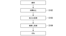
- a spring shape is obtained by performing cold spring processing S100 on the steel wire for a spring according to the present embodiment.
- the wire is cold-worked S102 into a spring shape, and then quenching treatment S103 and tempering are performed.
- Process S104 is performed.
- the wire is hot-worked S101 into a spring shape, and then the quenching treatment S103 and tempering are performed.
- Process S104 is performed.
- the wire rod When the wire rod is cold-worked S102 into a spring shape, specifically, the wire rod composed of the above-mentioned chemical components is cold-worked S102 into a spring shape and then heated to 850 to 1050 ° C. to perform the tempering treatment S103.
- the tempering process is performed under the conditions that the tempering temperature T [K], the tempering time t [s], the C content C% [mass%] and the Cr content Cr% [mass%] satisfy the formula (2).
- Cold working S102 and hot working S101 the method of cold working S102 and the method of hot working S101 when the wire rod is spring-processed to obtain a spring shape are not particularly limited. A known method can be used. Further, the heating method is not limited. In the method for manufacturing a spring according to the present embodiment, it is important to satisfy the above-mentioned chemical composition and to satisfy the quenching condition and tempering condition described later.
- the heating temperature for quenching of springs and spring steel wires shall be 850 ° C or higher in order to austenite the structure. On the other hand, if the heating temperature of quenching exceeds 1050 ° C., the austenite crystal grains are coarsened. Therefore, it is necessary to set the heating temperature of quenching in the range of 850 to 1050 ° C.
- a suitable quenching heating temperature range is 900 ° C to 990 ° C.
- the heating method may be furnace heating, high frequency induction heating furnace, or the like.
- the heating time is usually about 5 to 3000 seconds (s).
- Hardening may be performed by heating the steel wire for a spring to form it into a spring shape hot, and then cooling the quenching (so-called hot forming spring).
- the quenching and cooling method may be oil cooling or water cooling. Quenching yields a martensite-based tissue.
- Tempering condition After quenching, tempering is performed under the condition of the formula (2) in order to achieve both high strength and high toughness. 58000 ⁇ (T + 700 ⁇ [C%] + 50 ⁇ [Cr%]) ⁇ (51.7 + log) ⁇ 62000 ⁇ ⁇ ⁇ Equation (2)
- T tempering temperature (K)
- t tempering time (s)
- [C%] C content [mass%]
- Cr Cr content [mass%].
- log is a common logarithm of t.
- the unit of tempering temperature is absolute temperature, not Celsius temperature.
- a suitable lower limit of the value of (T + 700 ⁇ [C%] + 50 ⁇ [Cr%]) ⁇ (51.7 + logt) under the tempering condition is 59000. Further, a suitable upper limit is 61000.
- the cooling means after tempering may be either air cooling or water cooling, and is not particularly specified.
- a steel wire for a spring manufactured by performing quenching treatment S103 and tempering treatment S104 while keeping the straight line of the wire without performing hot spring processing is cooled as shown in FIG.
- Spring processing S100 may be performed between them, and then strain removal and annealing may be performed. Strain removal annealing may be carried out under the conditions described in, for example, known document A.
- the springs manufactured by hot working or cold working are both used as suspension springs through processes such as shot peening, painting, and setting.
- Known Document A Spring Papers, No. 58 (2013) p. 49
- the spring according to the present invention includes the following two forms.
- Spring A A wire rod as a material is drawn out to have a desired wire diameter, and then quenching treatment S103 and tempering treatment S104 are added to obtain a steel wire for a spring according to the present invention, and then cold working is performed.
- Spring B Hot working S101 or cold working S102 is added to a wire material that can be a material for the steel wire for spring according to the present invention to form a spring shape, and then quenching treatment S103 and tempering treatment S104 are added. Spring to be manufactured.
- the spring A has the same metal structure and iron carbide state as the spring steel wire according to the present invention, and has the same level of exhibited characteristics. Since the quenching treatment S103 and the tempering treatment S104, which are heat treatments that affect the metal structure of the spring B, coincide with the quenching treatment S103 and the tempering treatment S104 in the manufacturing process of the spring steel wire, the spring steel according to the present invention. It has the same metal structure and iron carbide state as the wire, and has the same level of exhibited characteristics. That is, although the springs (spring A and spring B) according to the present invention are not steel wires in shape, they have the same chemical composition, metal structure and iron carbide state as the steel wires for springs according to the present invention.
- the structure is a tempered martensite structure.
- the tempered martensite structure referred to here refers to a structure mainly composed of tempered martensite formed by quenching and tempering, and includes retained austenite and iron carbide in the structure.
- ferrite, pearlite, and bainite which are clearly distinguishable from the tempered martensite structure, need to be suppressed to a total area ratio of 5% or less.
- Steel materials having the chemical components shown in Table 1 were produced by converter melting and continuous casting, or test furnace vacuum melting and ingot casting. The content of the alloy not intentionally added is left blank in Table 1. The unit of all chemical components shown in Table 1 was mass%, and the balance was iron and impurities. In Table 1, values outside the scope of the invention are underlined. In other tables, values outside the scope of the invention or values that do not meet the pass / fail criteria are underlined. If necessary, the steel material was subjected to soaking heat diffusion treatment. After that, the continuous cast material was formed into a wire rod shape having a diameter of 13 mm through a block rolling step and a hot rolling step. The ingot casting material was subjected to hot forging and cutting to obtain a wire rod shape having a diameter of 13 mm.
- the wire rod was drawn out to a diameter of 12 mm, heated to 950 ° C. in a heating furnace, held for 30 minutes (1800 s), and then immediately put into oil (oil quenching) to quench the wire rod. ..
- oil quenching instead of oil quenching, some wire rods were quenched by heating to 980 ° C. in a high frequency induction heating furnace, holding for 10 seconds, and then cooling the fountain (water quenching).
- the hardened wire was tempered under the conditions shown in Table 2. The tempering method was furnace heating and air cooling for the oil-quenched material, and high-frequency induction heating and water cooling for the water-quenched material.
- a No. 14A tensile test piece with a parallel part diameter of 6 mm was prepared according to JIS Z 2241: 2011, and a length of 55 mm was obtained according to JIS Z 2242: 2005.
- a 2 mm-U notch impact test piece (subsize, width 5 mm) was prepared. Each of these test pieces was subjected to a tensile test based on JIS Z 2241: 2011 and a Charpy impact test based on JIS Z 2242: 2005.
- each spring steel wire was cut vertically in the longitudinal direction and polished to prepare a test piece for observing the metallographic structure.
- R the radius of the steel wire for spring
- the range of the field of view of 100 ⁇ m ⁇ 100 ⁇ m is confirmed with an optical microscope at the point of depth R / 2 from the surface, and the structure corresponding to non-tempering martensite is 5. It was confirmed whether or not it existed in% or more.
- the mechanical properties of the steel wire for springs were evaluated as follows. In the tensile test, the tensile strength and 0.2% proof stress were measured to determine the yield ratio. The tensile strength and yield ratio suitable for the high-strength suspension spring were 2000 MPa or more and 85% or more, respectively. If this is satisfied, it is determined that the strength and the sagging characteristics are good when used as a suspension spring.
- the test temperature of the Charpy impact test was 20 ° C. Further, a steel wire having an impact value of 60 J / cm 2 or more was regarded as a steel wire having good toughness.
- a test piece (diameter 3 mm ⁇ thickness 1 mm) for measuring differential scanning calorimetry was collected from a steel wire for a spring that had been quenched and tempered.
- DSC-60 manufactured by Shimadzu Corporation was used as the differential scanning calorimeter.
- the measurement conditions for the differential scanning calorimetry were as follows. ⁇ Atmospheric gas: N 2 (30 ml / min) -Measurement temperature range: 50 ° C to 600 ° C ⁇ Cell: Aluminum ⁇ Reference: ⁇ -Al 2 O 3 ⁇ Temperature rise rate: 0.25 ° C / s The DSC curve was measured under these conditions, and the area ratio (%) of the peak region of 450 ° C.
- the “peak area ratio (%) of 450 ° C. or lower” in Table 3 refers to 450 ° C. or less of the peaks of the exothermic reaction with respect to the total area 3 of the peaks of the exothermic reaction. It means the ratio of the area 4 of the area.
- the spring of the present invention has the same chemical composition and characteristics as the steel wire for spring of the present invention. Therefore, in the examples, since the chemical composition and the mechanical properties of the spring are the same as those of the steel wire for the spring, the description of these values is omitted.
- the test number No. in Table 3 In all of 1 to 35 and 2a, a peak of 10 mW / g or more was observed as an exothermic reaction corresponding to peak 2.
- Example No. of the present invention As shown in Table 3, Example No. of the present invention.
- the steel wires for springs 1 to 23 had excellent characteristics.
- the examples of the inventions shown in the table assume steels that have not been machined and subjected to strain-relief tempering after quenching and tempering (steel wires for springs and springs that have been quenched and tempered after spring forming: the above-mentioned spring B). It was done. Further investigation to confirm that the steel wire for spring belonging to this steel has the necessary mechanical properties even after being subjected to machining and strain removal annealing to form a spring (spring A described above). was done. Specifically, No. The same applies to the sample (denoted as No. 2a) obtained by subjecting the steel wire for spring No. 2 to cold drawing with a surface reduction rate of 5% and then performing strain removal annealing at 400 ° C.
Landscapes
- Chemical & Material Sciences (AREA)
- Engineering & Computer Science (AREA)
- Mechanical Engineering (AREA)
- Materials Engineering (AREA)
- Metallurgy (AREA)
- Organic Chemistry (AREA)
- Physics & Mathematics (AREA)
- Thermal Sciences (AREA)
- Crystallography & Structural Chemistry (AREA)
- Heat Treatment Of Articles (AREA)
- Heat Treatment Of Strip Materials And Filament Materials (AREA)
- Heat Treatment Of Steel (AREA)
Priority Applications (2)
| Application Number | Priority Date | Filing Date | Title |
|---|---|---|---|
| PCT/JP2020/021159 WO2021240740A1 (ja) | 2020-05-28 | 2020-05-28 | ばね用鋼線、ばね及びそれらの製造方法 |
| JP2022527408A JP7260838B2 (ja) | 2020-05-28 | 2020-05-28 | ばね用鋼線、ばね及びそれらの製造方法 |
Applications Claiming Priority (1)
| Application Number | Priority Date | Filing Date | Title |
|---|---|---|---|
| PCT/JP2020/021159 WO2021240740A1 (ja) | 2020-05-28 | 2020-05-28 | ばね用鋼線、ばね及びそれらの製造方法 |
Publications (1)
| Publication Number | Publication Date |
|---|---|
| WO2021240740A1 true WO2021240740A1 (ja) | 2021-12-02 |
Family
ID=78723220
Family Applications (1)
| Application Number | Title | Priority Date | Filing Date |
|---|---|---|---|
| PCT/JP2020/021159 Ceased WO2021240740A1 (ja) | 2020-05-28 | 2020-05-28 | ばね用鋼線、ばね及びそれらの製造方法 |
Country Status (2)
| Country | Link |
|---|---|
| JP (1) | JP7260838B2 (https=) |
| WO (1) | WO2021240740A1 (https=) |
Cited By (2)
| Publication number | Priority date | Publication date | Assignee | Title |
|---|---|---|---|---|
| WO2025220585A1 (ja) * | 2024-04-16 | 2025-10-23 | 日本発條株式会社 | ばね部材 |
| WO2025220584A1 (ja) * | 2024-04-16 | 2025-10-23 | 日本発條株式会社 | ばね部材 |
Citations (3)
| Publication number | Priority date | Publication date | Assignee | Title |
|---|---|---|---|---|
| JPH1129839A (ja) * | 1997-05-12 | 1999-02-02 | Nippon Steel Corp | 高靭性ばね鋼 |
| JP2001181794A (ja) * | 1999-12-20 | 2001-07-03 | Nippon Steel Corp | 高強度ばね用鋼材 |
| JP2004143482A (ja) * | 2002-10-22 | 2004-05-20 | Nippon Steel Corp | 高強度冷間成形ばね用鋼線とその製造方法 |
-
2020
- 2020-05-28 WO PCT/JP2020/021159 patent/WO2021240740A1/ja not_active Ceased
- 2020-05-28 JP JP2022527408A patent/JP7260838B2/ja active Active
Patent Citations (3)
| Publication number | Priority date | Publication date | Assignee | Title |
|---|---|---|---|---|
| JPH1129839A (ja) * | 1997-05-12 | 1999-02-02 | Nippon Steel Corp | 高靭性ばね鋼 |
| JP2001181794A (ja) * | 1999-12-20 | 2001-07-03 | Nippon Steel Corp | 高強度ばね用鋼材 |
| JP2004143482A (ja) * | 2002-10-22 | 2004-05-20 | Nippon Steel Corp | 高強度冷間成形ばね用鋼線とその製造方法 |
Cited By (2)
| Publication number | Priority date | Publication date | Assignee | Title |
|---|---|---|---|---|
| WO2025220585A1 (ja) * | 2024-04-16 | 2025-10-23 | 日本発條株式会社 | ばね部材 |
| WO2025220584A1 (ja) * | 2024-04-16 | 2025-10-23 | 日本発條株式会社 | ばね部材 |
Also Published As
| Publication number | Publication date |
|---|---|
| JPWO2021240740A1 (https=) | 2021-12-02 |
| JP7260838B2 (ja) | 2023-04-19 |
Similar Documents
| Publication | Publication Date | Title |
|---|---|---|
| KR102020385B1 (ko) | 내부식 피로특성이 우수한 스프링용 선재, 강선 및 이들의 제조방법 | |
| JP6306711B2 (ja) | 耐遅れ破壊特性を有するマルテンサイト鋼および製造方法 | |
| KR101031679B1 (ko) | 스프링용 강 선재의 제조 방법 | |
| EP2058414B1 (en) | High-strength spring steel wire, high-strength springs and processes for production of both | |
| JP4709944B2 (ja) | 肌焼鋼、浸炭部品、及び肌焼鋼の製造方法 | |
| JP6027302B2 (ja) | 高強度焼戻し省略ばね用鋼 | |
| CN103556063A (zh) | 高强度弹簧用热处理钢 | |
| US20150101715A1 (en) | High strength steel wire for spring excellent in coiling performance and hydrogen embrittlement resistance and method for manufacturing same | |
| JP2005240175A (ja) | 浸炭時の粗大粒防止特性と疲労特性に優れた肌焼鋼とその製造方法 | |
| JP7133705B2 (ja) | 靭性及び腐食疲労特性が向上されたスプリング用線材、鋼線及びその製造方法 | |
| CN101528962A (zh) | 冷加工模具钢、模具和用于制造冷加工模具钢的方法 | |
| TW202233863A (zh) | 沃斯田鐵系不鏽鋼材及其製造方法、以及板彈簧 | |
| CN108315637B (zh) | 高碳热轧钢板及其制造方法 | |
| WO2022153790A1 (ja) | マルテンサイト系ステンレス鋼材及びその製造方法 | |
| CN116745455A (zh) | 具有改善的强度和耐腐蚀性的马氏体不锈钢及其制造方法 | |
| JP6798557B2 (ja) | 鋼 | |
| JP7260838B2 (ja) | ばね用鋼線、ばね及びそれらの製造方法 | |
| JP6766362B2 (ja) | 浸炭時の粗大粒防止特性と疲労特性と被削性に優れた肌焼鋼およびその製造方法 | |
| JP3328967B2 (ja) | 靭性および耐応力腐食割れ性に優れたマルテンサイト系ステンレス鋼継目無鋼管の製造法 | |
| EP3633060B1 (en) | Steel plate and method of manufacturing the same | |
| JP5601861B2 (ja) | ボロン鋼圧延焼鈍鋼板の製造法 | |
| JP7229827B2 (ja) | 高炭素鋼板の製造方法 | |
| JP7552959B1 (ja) | 熱間鍛造用非調質鋼並びに熱間鍛造材及びその製造方法 | |
| JP2001234236A (ja) | 強度・延性・靱性に優れたマルテンサイト系ステンレス鋼材の製造方法 | |
| JP3760847B2 (ja) | 平鋼ばね用鋼 |
Legal Events
| Date | Code | Title | Description |
|---|---|---|---|
| 121 | Ep: the epo has been informed by wipo that ep was designated in this application |
Ref document number: 20937612 Country of ref document: EP Kind code of ref document: A1 |
|
| ENP | Entry into the national phase |
Ref document number: 2022527408 Country of ref document: JP Kind code of ref document: A |
|
| NENP | Non-entry into the national phase |
Ref country code: DE |
|
| 122 | Ep: pct application non-entry in european phase |
Ref document number: 20937612 Country of ref document: EP Kind code of ref document: A1 |