WO2021235493A1 - Multilayer film, molded body, method for producing multilayer film, and method for producing molded body - Google Patents
Multilayer film, molded body, method for producing multilayer film, and method for producing molded body Download PDFInfo
- Publication number
- WO2021235493A1 WO2021235493A1 PCT/JP2021/019013 JP2021019013W WO2021235493A1 WO 2021235493 A1 WO2021235493 A1 WO 2021235493A1 JP 2021019013 W JP2021019013 W JP 2021019013W WO 2021235493 A1 WO2021235493 A1 WO 2021235493A1
- Authority
- WO
- WIPO (PCT)
- Prior art keywords
- coating layer
- laminated film
- layer
- resin composition
- base material
- Prior art date
Links
Images


Classifications
-
- B—PERFORMING OPERATIONS; TRANSPORTING
- B32—LAYERED PRODUCTS
- B32B—LAYERED PRODUCTS, i.e. PRODUCTS BUILT-UP OF STRATA OF FLAT OR NON-FLAT, e.g. CELLULAR OR HONEYCOMB, FORM
- B32B27/00—Layered products comprising a layer of synthetic resin
- B32B27/06—Layered products comprising a layer of synthetic resin as the main or only constituent of a layer, which is next to another layer of the same or of a different material
- B32B27/08—Layered products comprising a layer of synthetic resin as the main or only constituent of a layer, which is next to another layer of the same or of a different material of synthetic resin
-
- B—PERFORMING OPERATIONS; TRANSPORTING
- B32—LAYERED PRODUCTS
- B32B—LAYERED PRODUCTS, i.e. PRODUCTS BUILT-UP OF STRATA OF FLAT OR NON-FLAT, e.g. CELLULAR OR HONEYCOMB, FORM
- B32B27/00—Layered products comprising a layer of synthetic resin
- B32B27/16—Layered products comprising a layer of synthetic resin specially treated, e.g. irradiated
-
- B—PERFORMING OPERATIONS; TRANSPORTING
- B32—LAYERED PRODUCTS
- B32B—LAYERED PRODUCTS, i.e. PRODUCTS BUILT-UP OF STRATA OF FLAT OR NON-FLAT, e.g. CELLULAR OR HONEYCOMB, FORM
- B32B3/00—Layered products comprising a layer with external or internal discontinuities or unevennesses, or a layer of non-planar form; Layered products having particular features of form
- B32B3/26—Layered products comprising a layer with external or internal discontinuities or unevennesses, or a layer of non-planar form; Layered products having particular features of form characterised by a particular shape of the outline of the cross-section of a continuous layer; characterised by a layer with cavities or internal voids ; characterised by an apertured layer
- B32B3/30—Layered products comprising a layer with external or internal discontinuities or unevennesses, or a layer of non-planar form; Layered products having particular features of form characterised by a particular shape of the outline of the cross-section of a continuous layer; characterised by a layer with cavities or internal voids ; characterised by an apertured layer characterised by a layer formed with recesses or projections, e.g. hollows, grooves, protuberances, ribs
-
- B—PERFORMING OPERATIONS; TRANSPORTING
- B32—LAYERED PRODUCTS
- B32B—LAYERED PRODUCTS, i.e. PRODUCTS BUILT-UP OF STRATA OF FLAT OR NON-FLAT, e.g. CELLULAR OR HONEYCOMB, FORM
- B32B37/00—Methods or apparatus for laminating, e.g. by curing or by ultrasonic bonding
- B32B37/10—Methods or apparatus for laminating, e.g. by curing or by ultrasonic bonding characterised by the pressing technique, e.g. using action of vacuum or fluid pressure
- B32B37/1054—Regulating the dimensions of the laminate, e.g. by adjusting the nip or platen gap
-
- B—PERFORMING OPERATIONS; TRANSPORTING
- B32—LAYERED PRODUCTS
- B32B—LAYERED PRODUCTS, i.e. PRODUCTS BUILT-UP OF STRATA OF FLAT OR NON-FLAT, e.g. CELLULAR OR HONEYCOMB, FORM
- B32B38/00—Ancillary operations in connection with laminating processes
- B32B38/06—Embossing
-
- B—PERFORMING OPERATIONS; TRANSPORTING
- B32—LAYERED PRODUCTS
- B32B—LAYERED PRODUCTS, i.e. PRODUCTS BUILT-UP OF STRATA OF FLAT OR NON-FLAT, e.g. CELLULAR OR HONEYCOMB, FORM
- B32B7/00—Layered products characterised by the relation between layers; Layered products characterised by the relative orientation of features between layers, or by the relative values of a measurable parameter between layers, i.e. products comprising layers having different physical, chemical or physicochemical properties; Layered products characterised by the interconnection of layers
- B32B7/02—Physical, chemical or physicochemical properties
- B32B7/022—Mechanical properties
-
- B—PERFORMING OPERATIONS; TRANSPORTING
- B32—LAYERED PRODUCTS
- B32B—LAYERED PRODUCTS, i.e. PRODUCTS BUILT-UP OF STRATA OF FLAT OR NON-FLAT, e.g. CELLULAR OR HONEYCOMB, FORM
- B32B7/00—Layered products characterised by the relation between layers; Layered products characterised by the relative orientation of features between layers, or by the relative values of a measurable parameter between layers, i.e. products comprising layers having different physical, chemical or physicochemical properties; Layered products characterised by the interconnection of layers
- B32B7/02—Physical, chemical or physicochemical properties
- B32B7/023—Optical properties
-
- C—CHEMISTRY; METALLURGY
- C08—ORGANIC MACROMOLECULAR COMPOUNDS; THEIR PREPARATION OR CHEMICAL WORKING-UP; COMPOSITIONS BASED THEREON
- C08J—WORKING-UP; GENERAL PROCESSES OF COMPOUNDING; AFTER-TREATMENT NOT COVERED BY SUBCLASSES C08B, C08C, C08F, C08G or C08H
- C08J7/00—Chemical treatment or coating of shaped articles made of macromolecular substances
- C08J7/04—Coating
- C08J7/046—Forming abrasion-resistant coatings; Forming surface-hardening coatings
-
- B—PERFORMING OPERATIONS; TRANSPORTING
- B32—LAYERED PRODUCTS
- B32B—LAYERED PRODUCTS, i.e. PRODUCTS BUILT-UP OF STRATA OF FLAT OR NON-FLAT, e.g. CELLULAR OR HONEYCOMB, FORM
- B32B2255/00—Coating on the layer surface
- B32B2255/10—Coating on the layer surface on synthetic resin layer or on natural or synthetic rubber layer
-
- B—PERFORMING OPERATIONS; TRANSPORTING
- B32—LAYERED PRODUCTS
- B32B—LAYERED PRODUCTS, i.e. PRODUCTS BUILT-UP OF STRATA OF FLAT OR NON-FLAT, e.g. CELLULAR OR HONEYCOMB, FORM
- B32B2255/00—Coating on the layer surface
- B32B2255/26—Polymeric coating
-
- B—PERFORMING OPERATIONS; TRANSPORTING
- B32—LAYERED PRODUCTS
- B32B—LAYERED PRODUCTS, i.e. PRODUCTS BUILT-UP OF STRATA OF FLAT OR NON-FLAT, e.g. CELLULAR OR HONEYCOMB, FORM
- B32B2307/00—Properties of the layers or laminate
- B32B2307/50—Properties of the layers or laminate having particular mechanical properties
- B32B2307/536—Hardness
-
- B—PERFORMING OPERATIONS; TRANSPORTING
- B32—LAYERED PRODUCTS
- B32B—LAYERED PRODUCTS, i.e. PRODUCTS BUILT-UP OF STRATA OF FLAT OR NON-FLAT, e.g. CELLULAR OR HONEYCOMB, FORM
- B32B2310/00—Treatment by energy or chemical effects
- B32B2310/08—Treatment by energy or chemical effects by wave energy or particle radiation
-
- B—PERFORMING OPERATIONS; TRANSPORTING
- B32—LAYERED PRODUCTS
- B32B—LAYERED PRODUCTS, i.e. PRODUCTS BUILT-UP OF STRATA OF FLAT OR NON-FLAT, e.g. CELLULAR OR HONEYCOMB, FORM
- B32B2333/00—Polymers of unsaturated acids or derivatives thereof
- B32B2333/04—Polymers of esters
- B32B2333/12—Polymers of methacrylic acid esters, e.g. PMMA, i.e. polymethylmethacrylate
-
- B—PERFORMING OPERATIONS; TRANSPORTING
- B32—LAYERED PRODUCTS
- B32B—LAYERED PRODUCTS, i.e. PRODUCTS BUILT-UP OF STRATA OF FLAT OR NON-FLAT, e.g. CELLULAR OR HONEYCOMB, FORM
- B32B2369/00—Polycarbonates
Definitions
- the present invention relates to a laminated film and a molded product, and a method for producing these.
- the display is used for various electrical components such as computers, televisions, mobile phones, personal digital assistants (tablet personal computers, mobile devices, electronic organizers, etc.), in-vehicle devices, and the like.
- Patent Document 1 discloses a film having a convex portion having a height of 100 nm or more and 250 nm or less.
- the protective material has a design in which a plurality of areas having different surface textures such as textures are seamlessly formed (hereinafter referred to as seamless design), for example, an information display part of a display and a bezel part surrounding the information display part are integrated.
- seamless design a design in which a plurality of areas having different surface textures such as textures are seamlessly formed
- an information display part of a display and a bezel part surrounding the information display part are integrated.
- An object of the present invention is to provide a laminated film having excellent shapeability and mold releasability, which is suitable for realizing a seamless design.
- the coating layer contains an active energy ray-curable resin composition and contains.
- the thickness of the coating layer is more than 2 ⁇ m.
- the indentation hardness HB 100 by the nanoindentation method at an indentation depth of 100 nm of the coating layer is 0.30 GPa or more and 0.65 GPa or less.
- the indentation hardness HB 2000 by the nanoindentation method at an indentation depth of 2000 nm of the coating layer is 0.15 GPa or more and 0.35 GPa or less.
- the indentation hardness HB 2000 is a laminated film smaller than the indentation hardness HB 100.
- the thickness of the coating layer is more than 2 ⁇ m.
- the indentation hardness HB 100 by the nanoindentation method at an indentation depth of 100 nm of the coating layer is 0.30 GPa or more and 0.65 GPa or less.
- the indentation hardness HB 2000 by the nanoindentation method at an indentation depth of 2000 nm of the coating layer is 0.15 GPa or more and 0.35 GPa or less.
- the indentation hardness HB 2000 is a method for producing a laminated film, which is smaller than the indentation hardness HB 100.
- a cured resin layer disposed on at least one main surface of the transparent support substrate.
- the main surface of the cured resin layer on the opposite side of the transparent supporting base material includes a first region in which irregularities are formed and a second region other than that.
- the first region and the second region are integrally formed.
- the cured resin layer is arranged on one main surface of the transparent supporting base material, and is arranged on one main surface.
- the cured resin layer is arranged on one main surface of the transparent supporting base material, and is arranged on one main surface.
- the coating layer is arranged on one main surface of the transparent supporting base material.
- the coating layer is arranged on one main surface of the transparent supporting base material.
- the coating layer is opposed to the mold, and the molding resin is injected toward the transparent support base material to form the molding resin layer together with the unevenness on the coating layer.
- the mold imparts a three-dimensional shape to the laminated film and gives the laminated film a three-dimensional shape.
- a layer containing a cured resin (hereinafter, may be referred to as a cured resin layer) is usually arranged on the outermost side of the protective material.
- a region corresponding to an information display portion of a display and a region corresponding to a bezel need to be integrally formed on this cured resin layer. That is, on the surface of the cured resin layer, a region having unevenness and a region having a different texture (texture), for example, a glossy feeling must be formed.
- texture for example, a glossy feeling
- the region having unevenness and the region having a texture different from this are formed by, for example, pressing a mold having an uneven portion and a flat portion against a cured resin layer (coating layer) that is neither completely uncured nor completely cured. Will be done. If the tackiness of the coating layer is large, the surface of the coating layer, which is particularly in close contact with the flat portion, becomes rough or whitened when peeled from the mold, and it is difficult to obtain a desired texture. The tackiness of the coating layer is affected by the hardness of the coating layer in the vicinity of the surface.
- the ease of forming irregularities is affected by the hardness inside the coating layer.
- the hardness inside the coating layer is excessively low, the restoration rate becomes high and unevenness is difficult to form.
- the hardness at the internal position of the coating layer to the same extent as the height of the applied convex portion has a great influence on the easiness of forming the unevenness.
- the present embodiment focuses on the hardness near and inside the surface of the coating layer, and provides a laminated film having a coating layer in which these satisfy a specific range and relationship.
- a coating layer is neither completely uncured nor completely cured. Therefore, the coating layer has both hardness that allows unevenness to be transferred and low tackiness that can be easily peeled off from the mold. Therefore, it is possible to simultaneously form a plurality of regions having different textures on the coating layer, for example, an uneven region and a smooth region.
- the coating layer formed into a three-dimensional shape (for example, preformed) can be uncured or semi-cured, it is easy to stretch. Therefore, it is also possible to form the laminated film into a complicated three-dimensional shape. In addition, these shapes are retained for a long period of time by completely curing the coating layer after imparting irregularities and, if necessary, three-dimensional shapes.
- a seamless design is realized by using the laminated film according to this embodiment. That is, the laminated film according to this embodiment is suitable as a material for a molded product having a seamless design.
- the laminated film according to this embodiment is particularly suitable as a material for a large molded body having the above-mentioned seamless design.
- the laminated film according to the present embodiment includes a transparent support base material and a coating layer arranged on at least one main surface of the transparent support base material.
- the thickness of the coating layer is more than 2 ⁇ m.
- the coating layer contains an active energy ray-curable resin composition.
- the indentation hardness HB 100 by the nanoindentation method at an indentation depth of 100 nm of the coating layer is 0.30 GPa or more and 0.65 GPa or less.
- the indentation hardness HB 2000 by the nanoindentation method at an indentation depth of 2000 nm of the coating layer is 0.15 GPa or more and 0.35 GPa or less.
- the indentation hardness HB 2000 is smaller than the indentation hardness HB 100. It can be said that such a coating layer is in a state of neither completely uncured nor completely cured (hereinafter, referred to as semi-cured or semi-cured state).
- the indentation hardness HB 100 indicates the hardness in the vicinity of the surface of the coating layer (hereinafter, may be referred to as surface hardness).
- the indentation hardness HB 2000 indicates the hardness inside the coating layer (hereinafter, may be referred to as internal hardness).
- the inside of the coating layer is a region of the coating layer on the transparent support base material side. The greater the indentation hardness, the higher the hardness. The hardness of the coating layer may decrease from the surface toward the transparent supporting substrate.
- the internal hardness of the coating layer is dominant in the ease of forming irregularities. If the internal hardness is low, the coating layer can be easily deformed along the unevenness of the pressed mold. However, if the hardness of the coating layer is excessively low, the coating layer tends to return to its original shape when the laminated film is removed from the mold. This tendency is remarkable when the convex part is high.
- the coating layer has an internal hardness sufficient to transfer and maintain the unevenness.
- the surface hardness of the coating layer is high, and it exhibits low tackiness and is not easily deformed. That is, the deformation of the unevenness when peeled from the mold is suppressed by the high surface hardness of the coating layer. Therefore, desired unevenness can be easily formed on the laminated film according to the present embodiment.
- the coating layer is provided with the relatively high convex portion as described above, and the hardness of the coating layer at a depth of 2000 nm is focused on.
- Patent Document 1 defines the parameter ⁇ related to the ratio of the elastic component to the viscous component to be 80 or more and 94 or less. This value indicates that the restoration rate is high when the indenter is pushed into the coating layer.
- a high recovery rate means that the coating layer, at least in the vicinity of the surface, has a low hardness and high elasticity.
- the inside of the coating layer is usually less hard than the surface. That is, the inside of the coating layer has higher elasticity. As described above, it is difficult to accurately form a convex portion having a high elasticity of 300 nm or more on a coating layer having high elasticity both on the surface and inside and a high restoration rate.
- the indentation hardness HB 100 is 0.30 GPa or more, the surface of the coating layer exhibits low tackiness and is not easily deformed. Therefore, the coating layer is easily peeled off from the mold. That is, the laminated film can be peeled off while maintaining the pattern of the mold transferred to the surface of the coating layer with high accuracy.
- the indentation hardness HB 100 is 0.65 GPa or less, it becomes easy to stretch the laminated film. Therefore, the laminated film can be formed into a complicated three-dimensional shape while suppressing the occurrence of cracks.
- the coating layer has a hardness such that unevenness is easily formed. That is, the coating layer has excellent formability. Therefore, a desired pattern can be imparted to the coating layer.
- the indentation hardness HB 2000 is smaller than the indentation hardness HB 100, the vicinity of the surface and the inside of the coating layer can exert their respective functions. That is, the coating layer exhibits excellent releasability and formability.
- the coating layer can be completely cured after giving the laminated film fine irregularities and, if necessary, a three-dimensional shape. As a result, the imparted unevenness and three-dimensional shape are maintained for a long period of time. That is, the obtained molded product has excellent shape retention.
- the measurement target of the indentation hardness HB 100 and the indentation hardness HB 2000 is the laminated film immediately before the fine irregularities are formed.
- the coating layer in the laminated film to be measured is in a semi-cured state.
- the laminated film after the indentation hardness is measured and before the unevenness is formed may be heat-treated, decorated, or preformed. After heat treatment, decoration, and preformation, the indentation hardness HB 100 and the indentation hardness HB 2000 may be measured.
- the indentation hardness H by the nanoindentation method is determined by, for example, continuous stiffness measurement using a nanoindentation device.
- a minute load (alternating current (AC) load) is applied to the sample in addition to a quasi-static test load (direct current (DC) load).
- AC alternating current
- DC direct current
- the stiffness with respect to the depth is calculated from the vibration component of the resulting displacement and the phase difference between the displacement and the load. This makes it possible to obtain a continuous profile of hardness with respect to the depth.
- the hardness at a depth of 100 nm is the indentation hardness HB 100 or HA 100 described later
- the hardness at 2000 nm is the indentation hardness HB 2000 or HA 2000 described later.
- the continuous rigidity measurement method includes, for example, Advanced Dynamic E and H. NMT methods can be used.
- the nanoindentation device include NANOMECHANICS, INC. IMicro Nanoindenter made by the company can be used.
- iMicro dedicated software may be used to calculate the load and stiffness.
- the sample is loaded by an indenter until a maximum load of 50 mN is reached.
- As the indenter for example, a verkovic type diamond indenter is used.
- the indenter for example, a verkovic type diamond indenter is used.
- the stiffness the Poisson's ratio, the load, etc. of the coating layer may be appropriately set to appropriate values.
- the elongation rate of the laminated film at 160 ° C. is preferably 5.0% or more.
- the laminated film exhibits a sufficient elongation at a molding temperature of 180 ° C. or lower. Therefore, the laminated film is easily formed into a three-dimensional shape. In particular, in the preform step described later, damage to the laminated film is easily suppressed.
- the elongation rate is more preferably 8.0% or more, and particularly preferably 10% or more.
- the elongation rate may be 500% or less, and may be 200% or less. Forming in the present specification is a concept including molding by a preform step and an unevenness forming step.
- the elongation rate is measured according to JIS K7127. Specifically, a test piece obtained by cutting a laminated film into a length of 200 mm and a width of 10 mm and a tensile tester having a chuck-to-chuck distance of 150 mm are used. The long side of the test piece is stretched by 2.5% under the condition of a tensile speed of 300 mm / min in an atmosphere of 160 ° C. Then, the test piece is observed with a microscope having a magnification of 1000 times or more to confirm the presence or absence of cracks having a length exceeding 1 mm. If no cracks occur, a new test piece is cut out, and then the long side is stretched by 5%. Then, the crack generation is observed by the same procedure. This procedure is repeated, and the elongation rate when a crack having the above size is first confirmed is defined as the elongation rate of the laminated film. The above procedure may be repeated by increasing the elongation rate by, for example, 2.5%.
- the transparent support base material is a base material that supports the coating layer.
- the transparent supporting base material is not particularly limited as long as it is transparent. "Transparent” specifically means that the total light transmittance is 40% or more.
- the total light transmittance of the transparent supporting substrate is preferably 90% or more.
- the total light transmittance can be measured by a method according to JIS K 7631-1.
- the transparent supporting substrate may be colorless or colored.
- the transparent support base material is appropriately selected according to the application.
- the transparent supporting base material include a polycarbonate (PC) -based film, a polyester-based film such as polyethylene terephthalate and polyethylene naphthalate; a cellulose-based film such as diacetyl cellulose and triacetyl cellulose; and an acrylic-based film such as polymethyl methacrylate (PMMA).
- PC polycarbonate
- polyester-based film such as polyethylene terephthalate and polyethylene naphthalate
- a cellulose-based film such as diacetyl cellulose and triacetyl cellulose
- an acrylic-based film such as polymethyl methacrylate (PMMA).
- styrene films such as polystyrene and acrylonitrile / styrene copolymers
- olefin films such as polyvinyl chloride, polyethylene, polypropylene, polyolefins having a cyclic or norbornene structure, ethylene / propylene copolymers, etc .
- nylon, aromatic polyamides, etc. Amid-based film can be mentioned.
- the transparent supporting base material is a film containing resins such as polyimide, polysulfone, polyethersulfone, polyetheretherketone, polyphenylene sulfide, polyvinyl alcohol, polyvinylidene chloride, polyvinylbutyral, polyallylate, polyoxymethylene, and epoxy resin. It may be a film containing a mixture of these polymers.
- the transparent support base material may be a laminate of a plurality of films.
- the transparent support base material may be, for example, a laminate of an acrylic film and a polycarbonate film.
- the transparent supporting substrate may be optically anisotropic or isotropic.
- the magnitude of birefringence of the optically anisotropic transparent supporting substrate is not particularly limited.
- the phase difference of the transparent supporting substrate having anisotropy may be 1/4 ( ⁇ / 4) of the wavelength and may be 1/2 ( ⁇ / 2) of the wavelength.
- the thickness of the transparent support base material is appropriately set according to the use and manufacturing method of the laminated film and / or the molded product.
- the thickness of the transparent supporting base material is preferably 30 ⁇ m or more, more preferably 75 ⁇ m or more, and particularly preferably 200 ⁇ m or more from the viewpoint of strength and handleability.
- the thickness of the transparent supporting base material is preferably 500 ⁇ m or less, more preferably 400 ⁇ m or less, from the viewpoint of extensibility. In one embodiment, the thickness of the transparent supporting substrate is 75 ⁇ m or more and 500 ⁇ m or less.
- the transparent support base material has extensibility at the temperature at which the laminated film is formed into a three-dimensional shape. It is desirable that the transparent support substrate has, for example, extensibility at the molding temperature in the preform process.
- the molding temperature in the preform step is usually 180 ° C. or lower.
- the glass transition temperature (Tg) of the material constituting the transparent supporting base material is preferably not more than the molding temperature, that is, 180 ° C. or less.
- the coating layer contains an active energy ray-curable resin composition. However, the coating layer is neither completely cured nor completely uncured. The coating layer is in a semi-cured state. After various shapes such as unevenness are given to the laminated film, the shape is maintained for a long period of time by completely curing the coating layer.
- the semi-cured resin composition (coating layer) can be formed, for example, by irradiating the resin composition with active energy rays of 5 mJ / cm 2 or more and 150 mJ / cm 2 or less.
- the integrated light amount of the active energy rays for semi-curing the resin composition is not limited to this, and is appropriately set depending on the composition of the resin composition and the like.
- the active energy rays are irradiated so that the indentation hardness HB 100 and the indentation hardness HB 2000 of the coating layer satisfy the above range and relationship in consideration of the composition of the resin composition and the like. ..
- the resin composition irradiated with the active energy ray of 1500 mJ / cm 2 is usually completely cured.
- the cured resin layer (for example, the hard coat layer and / or the functional layer) in the molded product according to the present embodiment described later is also completely cured. That is, the physical characteristics of the resin composition irradiated with the active energy rays of 1500 mJ / cm 2 can be regarded as the physical characteristics of the cured resin layer in the molded product.
- the pencil hardness of the completely cured resin composition (cured resin layer) is, for example, H or more.
- a resin composition in which the resin composition has not been exposed to active energy rays or has been exposed to active energy rays of less than 5 mJ / cm 2 can be considered to be completely uncured.
- the coating layer may be one layer or may include two or more layers.
- the resin composition forming each layer may be the same or different as long as it contains an active energy ray-curable resin. Regardless of the number of layers, when the hardness at the indentation depths of 100 nm and 2000 nm satisfies the above range and relationship, a laminated film having excellent shapeability and mold releasability can be obtained.
- the coating layer preferably contains at least a semi-cured hard coat layer, and typically includes a semi-cured hard coat layer and a semi-cured functional layer.
- the hard coat layer is mainly provided to impart scratch resistance and high hardness to the molded product.
- the functional layer may be an optical interference layer.
- the optical interference layer is arranged outside the hard coat layer mainly to reduce the reflectance.
- the optical interference layer may be one layer and may include a plurality of layers.
- the optical interference layer is, for example, a layer having a high refractive index (hereinafter, may be referred to as a high refractive index layer or an HR layer), a layer having a medium refractive index (hereinafter, referred to as a medium refractive index layer or an MR layer).
- a layer having a medium refractive index layer or an MR layer There is) and at least one layer having a low refractive index (hereinafter, may be referred to as a low refractive index layer or an LR layer).
- the refractive index of the HR layer may be 1.55 or more and 2.00 or less.
- the refractive index of the MR layer may be 1.45 or more and 1.60 or less.
- the refractive index of the LR layer may be 1.35 or more and 1.50 or less.
- the functional layer may be a layer other than the optical interference layer, and may be provided with another layer together with the optical interference layer.
- the other layer include an antibacterial / antiviral layer and an antifouling layer.
- the antibacterial / antiviral layer and the antifouling layer are arranged, for example, outside the hard coat layer (further, the optical interference layer).
- the polymerization rate PB of the resin composition in the coating layer that is, the resin composition in the semi-cured state
- PA of the resin composition after irradiation with active energy rays at 1500 mJ / cm 2 that is, the resin composition in the completely cured state.
- the difference (
- ) is, for example, 15% or more.
- is in this range, the shape retention is further improved.
- the indentation hardness H of the coating layer and the hard coat layer can be controlled by the polymerization rate.
- the polymerization rate can be obtained by the following procedure based on, for example, an infrared absorption spectrum obtained by infrared spectroscopy (IR: Infrared Spectroscopy).
- the uncured coating layer is analyzed by a Fourier transform infrared spectrophotometer (FT-IR) from the surface of the coating layer opposite to the transparent supporting substrate.
- FT-IR Fourier transform infrared spectrophotometer
- the horizontal axis indicates the wave number (cm -1 ), and the vertical axis indicates the absorbance.
- the baseline between 690 cm -1 and 2015 cm -1 is determined.
- the values obtained by dividing the peak heights I BC1 and I BC2 by the peak heights I BO are defined as r B1 and r B2 , respectively.
- the polymerization rate PB (%) of the resin composition in the semi-cured state is calculated by (1-r B1 / r 01 ) ⁇ 100 or (1-r B2 / r 02 ) ⁇ 100.
- the values obtained by dividing the peak heights I AC1 and I AC2 by the peak height I AO are defined as r A1 and r A2 , respectively.
- the polymerization rate PA (%) of the cured resin composition is calculated by (1-r A1 / r 01 ) ⁇ 100 or (1-r B2 / r 02 ) ⁇ 100.
- the indentation hardness HB 100 is 0.30 GPa or more and 0.65 GPa or less.
- the indentation hardness HB 100 is preferably 0.40 GPa or more, more preferably 0.45 GPa or more.
- the indentation hardness HB 100 is preferably 0.60 GPa or less, more preferably 0.55 GPa or less, and particularly preferably 0.50 GPa or less.
- may be 0.05 GPa or more. When
- the indentation hardness HB 2000 is 0.15 GPa or more and 0.35 GPa or less.
- the indentation hardness HB 2000 is preferably 0.20 GPa or more.
- the indentation hardness HB 2000 is preferably 0.33 GPa or less.
- is preferably 0.05 GPa or more. When
- the difference between the indentation hardness HB 100 and the indentation hardness HB 2000 is not particularly limited. From the viewpoint of formability and releasability,
- the coating layer has extensibility at the temperature at which the laminated film is formed into a three-dimensional shape. It is desirable that the coating layer has extensibility, for example, at the molding temperature in the preform step described later.
- the molding temperature in the preform step is usually 180 ° C. or lower.
- the Tg of the resin composition in the coating layer is preferably not more than the molding temperature, that is, 180 ° C. or less.
- the coating layer is required to be easily peeled off from the mold used for forming unevenness.
- the temperature of the mold used for forming the unevenness is usually 50 ° C. or higher.
- the Tg of the resin composition in the coating layer is preferably 50 ° C. or higher, more preferably 60 ° C. or higher.
- the glass transition temperature is measured by a differential scanning calorimeter (DSC) conforming to JIS K7121.
- DSC differential scanning calorimeter
- the Tg of the resin composition in the coating layer is related to the degree of curing of the coating layer. By controlling Tg, the shapeability and releasability of the coating layer can be improved.
- the pencil hardness of the surface of the coating layer after irradiation with active energy rays at 1500 mJ / cm 2 is preferably H or higher, and more preferably 2H or higher, in that scratch resistance is more likely to be improved. Pencil hardness is measured according to JIS K 5600-5-4.
- Laminated films containing uncured optical interference layers have particularly excellent antireflection performance.
- the visual reflectance including the specularly reflected light in the wavelength region of 380 nm or more and 780 nm or less measured from the optical interference layer side of the laminated film is 0.1% or more and 4.0% or less.
- the second region also has excellent antireflection properties. Therefore, the molded body has less reflection due to external light, and the molded body has good display characteristics and good visibility.
- the visual reflectance in the second region of the molded product can be 0.1% or more and 4.0% or less.
- the visual reflectance of the laminated film and the molded product is preferably 0.1% or more and 3.0% or less, and more preferably 0.1% or more and 2.5% or less.
- the above-mentioned visual reflectance is obtained by measuring all reflected light including specular reflected light. That is, the specular reflectance is measured by a so-called SCI (Specular Component Include) method. Since this method is not easily affected by the surface condition of the object to be measured, the visual reflectance of the uncured layer can be measured.
- SCI Standard Component Include
- the visual reflectance of the laminated film can be measured by the following method.
- a black paint for example, product name: CZ-805 BLACK (manufactured by Nikko Bics Co., Ltd.)
- the dry film thickness is 3 ⁇ m or more and 6 ⁇ m or less. Apply so that Then, the evaluation sample M is prepared by leaving it to dry in a room temperature environment for 5 hours.
- a spectrocolorimeter for example, SD7000 manufactured by Nippon Denshoku Kogyo Co., Ltd.
- SD7000 manufactured by Nippon Denshoku Kogyo Co., Ltd.
- the visual reflectance of the molded product can be measured as follows.
- the evaluation sample N is prepared by irradiating the evaluation sample M prepared above with an active energy ray having an integrated light amount of more than 150 mJ / cm 2 (for example, an integrated light amount of 1500 mJ / cm 2).
- the visual reflectance is measured from the coating layer side of the obtained evaluation sample N in the same manner as described above.
- the thickness of the coating layer is not particularly limited as long as it is more than 2 ⁇ m.
- the thickness of the coating layer is preferably 3 ⁇ m or more, more preferably 5 ⁇ m or more, in that relatively high convex portions can be easily formed.
- the thickness of the coating layer is preferably 20 ⁇ m or less, more preferably 15 ⁇ m or less in that it is easily cured.
- the thickness of the coating layer is, for example, 3 ⁇ m or more and 20 ⁇ m or less. If the coating layer contains more than one layer, the thickness of the coating layer is the sum of these thicknesses.
- the thickness of the hard coat layer can be in the same range as the thickness of the above coating layer.
- the thickness of the functional layer per layer is, for example, 5 nm or more and 300 nm or less, and 10 nm or more and 200 nm or less.
- the thickness of the coating layer can be obtained from its cross section. Specifically, a 10 mm ⁇ 10 mm test piece is cut out from the laminated film. A section for observing a cross section is prepared from a test piece using a microtom. The obtained section is observed with a laser microscope or a transmission electron microscope, and the thickness of the coating layer at any 10 points is measured. The average value of these is taken as the thickness of the coating layer.
- the thickness of the transparent supporting base material is also obtained in the same manner.
- the microtome for example, RM2265 manufactured by Leica Microsystems is used.
- the laser microscope for example, VK8700 manufactured by KEYENCE is used.
- the resin composition comprises at least one selected from the group consisting of active energy ray-curable monomers, oligomers and polymers.
- the active energy ray is not particularly limited, and may be ionizing radiation such as ultraviolet rays, electron beams, ⁇ rays, ⁇ rays, and ⁇ rays.
- active energy ray-curable monomers, oligomers and polymers may be collectively referred to as resin components.
- the resin composition can control the polymerization rate and the indentation hardness H of the coating layer and the cured resin layer.
- each layer may be the same or different. Above all, it is preferable that each layer contains the same or the same kind of resin component. This is because the adhesion of each layer is improved and peeling between layers is less likely to occur.
- the resin composition comprises a polymerizable polymer.
- the polymerizable polymer facilitates the coating layer to be imparted with curability as well as low tackiness.
- the resin composition comprises at least one of a polymerizable and non-polymerizable polymer (hereinafter, may be collectively referred to as a polymer) and at least one of a polymerizable monomer and an oligomer.
- the polymer makes it easier to impart low tackiness to the coating layer.
- the formability is easily improved.
- the resin composition preferably contains both a polymerizable polymer and a non-polymerizable polymer, and at least one of a polymerizable monomer and an oligomer, from the viewpoint of facilitating the control of tackiness.
- the non-polymerizable polymer is a polymer that does not contain a polymerizable unsaturated group.
- the weight average molecular weight of the non-polymerizable polymer is 5,000 or more. From the viewpoint of tackiness, the weight average molecular weight of the non-polymerizable polymer is preferably 10,000 or more.
- the weight average molecular weight of the non-polymerizable polymer may be 200,000 or less, preferably 100,000 or less, and more preferably 80,000 or less.
- non-polymerizable polymer examples include urethane resin, acrylic resin, polyester resin, and epoxy resin.
- Acrylic resin is preferable from the viewpoint of transparency, tackiness, physical properties, and durability.
- the polymerizable polymer is a polymer containing a polymerizable unsaturated group.
- the weight average molecular weight of the polymerizable polymer is 5,000 or more. From the viewpoint of tackiness, the weight average molecular weight of the polymerizable polymer is preferably 10,000 or more.
- the weight average molecular weight of the non-polymerizable polymer may be 200,000 or less, preferably 100,000 or less, and more preferably 80,000 or less.
- the polymerizable polymer contains a polymer chain containing a carbon-carbon bond, an ether bond, a urea bond, an ester bond, a urethane bond, etc. as a main chain, and a polymerizable unsaturated group as a side chain or a terminal group. From the viewpoint of transparency, a polymer chain containing a carbon-carbon bond is preferable. From the viewpoint of formability, a polymer chain containing a urethane bond is preferable.
- the polymerizable unsaturated group is preferably 2 or more, more preferably 3 or more, and particularly preferably 5 or more.
- the polymerizable unsaturated group is not particularly limited. Of these, acryloyl group and methacryloyl group are preferable as the polymerizable unsaturated group.
- the preferable polymerizable polymer examples include urethane (meth) acrylate polymer and acrylic (meth) acrylate polymer.
- the urethane (meth) acrylate polymer is, for example, (1) a method of adding a compound having a hydroxyl group and an acryloyl group (or acryloyl group) to a polyisocyanate compound having a terminal isocyanate group in the molecule, or (2) poly. It can be prepared by a method of reacting an isocyanate group-containing (meth) acrylate monomer with a polyurethane polyol obtained by reacting an isocyanate compound with a polyol.
- polyisocyanate compound examples include 2,4-tolylene diisocyanate, 2,6-tolylene diisocyanate, 1,3-xylene diisocyanate, 1,4-xylene diisocyanate, xylylene diisocyanate, 1,5-naphthalenedi isocyanate, and m.
- Examples thereof include divalent or trivalent polyisocyanate compounds such as triphenylmethane triisocyanate and dimethylene triphenyl triisocyanate, and bullet-type adducts and isocyanurate ring-type adducts of these diisocyanates.
- Examples of the compound having a hydroxyl group and an acryloyl group (or methacryloyl group) in the above method (1) include pentaerythritol tri (meth) acrylate, dipentaerythritol penta (meth) acrylate, and 2-hydroxyethyl (meth) acrylate.
- Examples thereof include glycerol di (meth) acrylates and alkylene oxide-modified or lactone-modified compounds obtained by adding ethylene oxide, propylene oxide, ⁇ -caprolactone, ⁇ -butyrolactone and the like to these.
- Examples of the polyol in the above method (2) include ethylene glycol, propylene glycol, butylene glycol, neopentyl glycol, 1,6-hexanediol, trimethylolpropane, glycerin, pentaerythritol, polycaprolactone diol, polyester polyol, and poly.
- Examples include ether polyol.
- an active hydrogen-containing polymerizable monomer such as isocyanate ethyl acrylate, isocyanate propyl acrylate, and hydroxyethyl acrylate is mixed with a polyisocyanate compound such as hexamethylene diisocyanate.
- a polyisocyanate compound such as hexamethylene diisocyanate. Examples thereof include unsaturated compounds formed by addition.
- the urethane (meth) acrylate polymer may be a urethane urea (meth) acrylate polymer having a urea bond.
- the urethane urea (meth) acrylate polymer can be prepared, for example, by using a polyamine in combination with the polyol in the above method (2).
- the acrylic (meth) acrylate polymer is an acrylic polymer containing an acryloyl group and / or a methacryloyl group. Specifically, a compound obtained by adding (meth) acrylic acid to an acrylic resin copolymerized with glycidyl methacrylate, or 2-hydroxyethyl (meth) acrylate or 4-hydroxybutyl to an acrylic resin copolymerized with 2-acryloyloxyethyl isocyanate.
- Examples thereof include a compound to which (meth) acrylate and pentaerythritol tri (meth) acrylate are added, and a resin obtained by adding 2-acryloyloxyethyl isocyanate to an acrylic resin copolymerized with a hydroxyl group-containing monomer.
- the polymer is used alone or in combination of two or more.
- the polymer content is 5 parts by mass or more with respect to 100 parts by mass of the solid content of the resin composition HC.
- the polymer content is preferably 85 parts by mass or less, more preferably 60 parts by mass or less, and particularly preferably 45 parts by mass or less.
- the content of the polymer in the resin composition HC is, for example, more than 5 parts by mass and 85 parts by mass or less.
- the compounding ratio of the polymerizable polymer and the non-polymerizable polymer is not particularly limited.
- the content of the polymer is more than 5 parts by mass with respect to 100 parts by mass of the solid content of the resin composition R. It is preferable, 10 parts by mass or more is more preferable, and 15 parts by mass or more is particularly preferable.
- the content of the polymer is preferably 85 parts by mass or less, more preferably 60 parts by mass or less, and particularly preferably 25 parts by mass or less with respect to 100 parts by mass of the solid content of the resin composition R.
- the content of the polymer in the resin composition R is, for example, more than 5 parts by mass and 85 parts by mass or less.
- the compounding ratio of the polymerizable polymer and the non-polymerizable polymer is not particularly limited.
- the polymerizable oligomer is an oligomer containing a polymerizable unsaturated group.
- the weight average molecular weight of the polymerizable oligomer is 500 or more and less than 5,000.
- the weight average molecular weight of the polymerizable oligomer may be 2,000 or more.
- the polymerizable oligomer has the same composition as the polymerizable polymer except for the molecular weight.
- the polymerizable oligomer contains an oligomer chain containing a carbon-carbon bond, an ether bond, a urea bond, an ester bond, a urethane bond and the like as a main chain, and a polymerizable unsaturated group as a side chain or a terminal group. From the viewpoint of transparency, an oligomer chain containing a carbon-carbon bond is preferable. From the viewpoint of formability, an oligomer chain containing a urethane bond is preferable.
- the polymerizable unsaturated group is preferably 2 or more, more preferably 3 or more, and particularly preferably 5 or more.
- the polymerizable unsaturated group is not particularly limited. Of these, acryloyl group and methacryloyl group are preferable as the polymerizable unsaturated group.
- preferable polymerizable oligomer examples include urethane (meth) acrylate oligomer and acrylic (meth) acrylate oligomer.
- the urethane (meth) acrylate oligomer and the acrylic (meth) acrylate oligomer are prepared in the same manner as the urethane (meth) acrylate polymer and the acrylic (meth) acrylate polymer, respectively.
- the polymerizable oligomer is used alone or in combination of two or more.
- urethane (meth) acrylate oligomers or polymers examples include DPHA-40H, UX-5000, UX-5102D20, UX-5103D, UX-5005, UX-3204, and UX- manufactured by Nippon Kayaku Co., Ltd. 4101, UXT-6100, UX-6101, UX-8101, UX-0937, UXF-4001-M35, UXF-402; UF-8001G, UA-510H manufactured by Kyoeisha Chemical Co., Ltd .; EBECRYL manufactured by Daicel Ornex Co., Ltd.
- acrylic (meth) acrylate oligomers or polymers examples include Unidick V-6840, Unidick V-6841, Unidick V-6850, Unidick EMS-635, and Unidick WHV- manufactured by DIC Co., Ltd.
- the polymerizable monomer is a monomer containing a polymerizable unsaturated group.
- the molecular weight of the polymerizable monomer is not particularly limited.
- the polymerizable unsaturated group equivalent of the polymerizable monomer is 50 g / eq. The above may be sufficient, and 200 g / eq. It may be:
- the polymerizable monomer preferably has 2 or more, more preferably 3 or more, and particularly preferably 5 or more polymerizable unsaturated groups.
- Acryloyl group and methacryloyl group are preferably exemplified as the polymerizable unsaturated group.
- Preferred polymerizable monomers are polyfunctional (meth) acrylate monomers.
- the polyfunctional (meth) acrylate monomer can be prepared by a dehydration reaction between a polyhydric alcohol and (meth) acrylic acid, or a transesterification reaction between the polyhydric alcohol and a (meth) acrylic acid ester.
- Polymerizable unsaturated group equivalent is 50 g / eq. More than 200 g / eq.
- Examples of the polyfunctional (meth) acrylate monomer include ethylene glycol di (meth) acrylate, 1,6-hexanediol di (meth) acrylate, polyethylene glycol (200) di (meth) acrylate, and allyl (meth) acrylate.
- the polymerizable monomer is used alone or in combination of two or more.
- the content of the polymerizable oligomer is, for example, 5 parts by mass or more and 95 parts by mass or less with respect to 100 parts by mass of the solid content of the resin composition HC.
- the content of the polymerizable monomer is, for example, 5 parts by mass or more and 95 parts by mass or less with respect to 100 parts by mass of the solid content of the resin composition HC.
- the total content of the polymerizable monomer and / or the polymerizable oligomer is preferably 5 parts by mass or more, more preferably 10 parts by mass or more, based on 100 parts by mass of the solid content of the resin composition HC.
- the total content of the polymerizable monomer and / or the polymerizable oligomer is preferably 95 parts by mass or less, more preferably 70 parts by mass or less, based on 100 parts by mass of the solid content of the resin composition HC.
- the total content of the polymerizable monomer and / or the polymerizable oligomer in the resin composition HC is, for example, 5 parts by mass or more and 95 parts by mass or less with respect to 100 parts by mass of the solid content of the resin composition HC.
- the content of the polymerizable oligomer is, for example, 5 parts by mass or more and 85 parts by mass or less with respect to 100 parts by mass of the solid content of the resin composition R.
- the content of the polymerizable monomer is, for example, 5 parts by mass or more and 85 parts by mass or less with respect to 100 parts by mass of the solid content of the resin composition R.
- the total content of the polymerizable monomer and / or the polymerizable oligomer is preferably 5 parts by mass or more, more preferably 10 parts by mass or more, and 13 parts by mass or more with respect to 100 parts by mass of the solid content of the resin composition R. Especially preferable.
- the total content of the polymerizable monomer and / or the polymerizable oligomer is preferably 85 parts by mass or less, more preferably 60 parts by mass or less, based on 100 parts by mass of the solid content of the resin composition R.
- the total content of the polymerizable monomer and / or the polymerizable oligomer in the resin composition R is, for example, 5 parts by mass or more and 85 parts by mass or less with respect to 100 parts by mass of the solid content of the resin composition R.
- the resin composition contains translucent fine particles, if necessary.
- the translucent fine particles make it easier to improve the antiglare property and hardness of the coated layer (cured resin layer) after curing.
- the average particle size of the translucent fine particles may be, for example, 1.0 ⁇ m or more and 10 ⁇ m or less, and may be 0.5 ⁇ m or more and 10 ⁇ m or less.
- the average particle size refers to the particle size (D50) at which the cumulative volume conversion measured by the laser diffraction type particle size distribution meter is 50%.
- Translucent fine particles are transparent or translucent. Translucent means that the total light transmittance measured by a method conforming to JIS K 7631-1 is 30% or more and less than 40%.
- the translucent fine particles may be organic fine particles or inorganic fine particles.
- Commercially available products may be used as the translucent fine particles.
- Examples of commercially available translucent fine particles include Techpolymer SSX series (styrene-acrylic copolymer fine particles) manufactured by Sekisui Kasei Kogyo Co., Ltd., Chemisnow SX series (styrene polymer fine particles) manufactured by Soken Kagaku Co., Ltd.
- Chemisnow MX series (acrylic polymer fine particles), Seahoster KE-P manufactured by Nippon Catalyst Co., Ltd., KE-S series (silica fine particles), Soliostar RA (silicon-acrylic copolymer fine particles), Epostal S12 (melamine polymer fine particles) , Epostal MA series (styrene-acrylic copolymer fine particles), acrylic copolymer fine particles, MSP series manufactured by Nikko Rika Co., Ltd., NH series (silicone fine particles), AZ series manufactured by Shin Nihon Sumikin Materials Co., Ltd., AY series (alumina) Fine particles).
- the techpolymer SSX series (styrene-acrylic copolymer fine particles) Chemisnow SX series (styrene polymer fine particles) and the Epostal MA series (styrene-acrylic copolymer fine particles) are preferable.
- the resin composition contains a filler, if necessary.
- the filler alleviates volume shrinkage due to curing of the coating layer.
- the filler improves the scratch resistance of the coating layer after curing.
- the primary particle size of the filler is preferably 5 nm or more and 1,000 nm or less, more preferably 500 nm or less, and particularly preferably 100 nm or less from the viewpoint of transparency and stability.
- the primary particle size is measured from an image of a cross-sectional electron microscope using image processing software.
- the filler may be organic fine particles or inorganic fine particles. Of these, inorganic fine particles are preferable.
- inorganic fine particles for example, silica (SiO 2 ) particles, alumina particles, titania particles, tin oxide particles, antimony-doped tin oxide (abbreviation: ATO) particles, phosphorus-doped tin oxide particles, zinc oxide particles, and titanium oxide are supported by silver. Examples include particles in which silver is carried on silica / alumina particles, particles in which double metal (silver / zinc / copper) ions are carried on glass, and copper iodide particles. Of these, silica particles and alumina particles are more preferable from the viewpoint of cost and stability.
- the surface of the filler is preferably modified with an unsaturated group such as a (meth) acryloyl group.
- a commercially available product may be used as the filler.
- examples of commercially available silica particles include IPA-ST, MEK-STM, IBK-ST, PGM-ST, XBA-ST, MEK-AC-2101, and MEK- manufactured by Nissan Chemical Industries, Ltd. AC-2202, MEK-AC-4101 and MIBK-SD, PL-1-IPA, PL-1-TL, PL-2-IPA, PL-2-MEK and PL-3-TL manufactured by Fuso Chemical Industry Co., Ltd. , OSCAL series and ELECOM series manufactured by JGC Catalysts and Chemicals Co., Ltd., and NANOBYK-3605 manufactured by Big Chemie Japan.
- Examples of commercially available alumina particles include AS-150I and AS-150T manufactured by Sumitomo Osaka Cement Co., Ltd., NANOBYK-3601, NANOBYK-3602, and NANOBYK-3610 manufactured by Big Chemie Japan.
- Examples of commercially available phosphorus-doped tin oxide particles include HX-204 IP manufactured by Nissan Chemical Industries, Ltd. and PTOPGM15WT% -N09 manufactured by CIK Nanotech.
- Examples of the particles in which silver is supported on titanium oxide include ATOMY BALL- (S) manufactured by JGC Catalysts and Chemicals Co., Ltd.
- Examples of the particles in which silver is supported on the silica-alumina particles include ATOMY BALL- (UA), ELCOM NU-1023SIV, and ELCOM NU-1024SIV manufactured by JGC Catalysts and Chemicals.
- Examples of the silver-supported particles on the silica particles include Ion Pure ZAF HS manufactured by Ishizuka Glass Co., Ltd.
- Examples of the copper iodide particles include Cufitec BE4-ANA01, AA1-ANA01, BB2-ANA01, and BD3-ANA01 manufactured by NBC Meshtec Inc.
- the content of the filler is preferably 60 parts by mass or less, more preferably 30 parts by mass or less, and particularly preferably 15 parts by mass or less with respect to 100 parts by mass of the solid content of the resin composition HC.
- the content of the filler is preferably 0.1 part by mass or more, more preferably 1 part by mass or more, and particularly preferably 3 parts by mass or more with respect to 100 parts by mass of the solid content of the resin composition HC.
- the content of the filler in the resin composition HC is, for example, 0.1 part by mass or more and 60 parts by mass or less with respect to 100 parts by mass of the solid content of the resin composition HC.
- the content of the filler is preferably 1 part by mass or more, more preferably 5 parts by mass or more, and particularly preferably 7 parts by mass or more with respect to 100 parts by mass of the solid content of the resin composition R.
- the content of the filler is preferably 90 parts by mass or less with respect to 100 parts by mass of the solid content of the resin composition R.
- the content of the filler in the resin composition R is, for example, 1 part by mass or more and 90 parts by mass or less with respect to 100 parts by mass of the solid content of the resin composition R.
- the resin composition contains a photopolymerization initiator, if necessary.
- the blending amount of the photopolymerization initiator is preferably 0.01 part by mass or more and 10 parts by mass or less, and more preferably 1 part by mass or more and 10 parts by mass or less with respect to 100 parts by mass of the solid content of the resin composition.
- photopolymerization initiator examples include an alkylphenone-based photopolymerization initiator, an acylphosphine oxide-based photopolymerization initiator, a titanosen-based photopolymerization initiator, and an oxime ester-based polymerization initiator.
- alkylphenone-based photopolymerization initiator examples include 2,2-dimethoxy-1,2-diphenylethane-1-one, 1-hydroxy-cyclohexyl-phenyl-ketone, and 2-hydroxy-2-methyl-1-phenyl-.
- acylphosphine oxide-based photopolymerization initiator examples include 2,4,6-trimethylbenzoyl-diphenyl-phosphinoxide, 2,4,6-triethylbenzoyldiphenylphosphine oxide, and 2,4,6-triphenyl.
- Monoacylphosphine oxides such as benzoyldiphenylphosphine oxide; bis (2,4,6-trimethylbenzoyl) -phenylphosphinoxide, bis- (2,6-dimethoxybenzoyl) -2,4,4-trimethylpentylphos
- bisacylphosphine oxides such as fin oxides.
- titanosen-based photopolymerization initiator examples include bis ( ⁇ 5-2,4-cyclopentadiene-1-yl) -bis (2,6-difluoro-3- (1H-pyrrole-1-yl) -phenyl) titanium. Can be mentioned.
- Examples of the oxime ester-based polymerization initiator include 1.2-octanedione, 1- [4- (phenylthio)-, 2- (O-benzoyloxime)], etanone, 1- [9-ethyl-6- ( 2-Methylbenzoyl) -9H-carbazole-3-yl]-, 1- (0-acetyloxime), oxyphenylacetic acid, 2- [2-oxo-2-phenylacetoxyethoxy] ethyl ester, 2- (2- (2-) Hydroxyethoxy) ethyl ester can be mentioned.
- the photopolymerization initiator is used alone or in combination of two or more.
- a photopolymerization initiator having an absorption wavelength in a long wavelength region for example, a wavelength region of 370 nm or more is preferable.
- a photopolymerization initiator include the above-mentioned acylphosphine oxide-based photopolymerization initiator.
- 2,4,6-trimethylbenzoyldiphenylphosphine oxide is commercially available from IGM Resins B.V. as Omnirad TPO H.
- Bis (2,4,6-trimethylbenzoyl) -phenylphosphine oxide is commercially available from IGM Resins B.V. as Omnirad 819.
- the active energy rays are irradiated under mild curing conditions such as semi-curing the coating layer, it is difficult to obtain the desired hardness because the curing reaction does not easily proceed inside the coating layer.
- a photopolymerization initiator having an absorption wavelength in the long wavelength region, the curing reaction inside the coating layer is promoted.
- the resin composition contains a solvent, if necessary.
- the solvent is not particularly limited, and is appropriately selected depending on the components contained in the composition, the type of the substrate to be applied, the method of applying the composition, and the like.
- the solvent include aromatic solvents such as toluene and xylene; ketone solvents such as methyl ethyl ketone, acetone, methyl isobutyl ketone and cyclohexanone; diethyl ether, isopropyl ether, tetrahydrofuran, dioxane, ethylene glycol dimethyl ether and ethylene glycol diethyl ether.
- Ethereal solvents such as diethylene glycol dimethyl ether, diethylene glycol diethyl ether, propylene glycol monomethyl ether, anisole, phenetol; ester solvents such as ethyl acetate, butyl acetate, isopropyl acetate, ethylene glycol diacetate; dimethylformamide, diethylformamide, N-methylpyrrolidone Amid-based solvents such as; cellosolve-based solvents such as methyl cellosolve, ethyl cellosolve, and butyl cellosolve; alcohol-based solvents such as methanol, ethanol, propanol, isopropyl alcohol, butanol, and isobutyl alcohol; halogen-based solvents such as dichloromethane and chloroform. These may be used alone or in combination of two or more. Of these, ester-based solvents, ether-based solvents, alcohol-based solvents and ketone-based solvents are preferable
- the resin composition R preferably contains a refractive index lowering component that lowers the refractive index of the optical interference layer.
- the refractive index lowering component is, for example, in the form of particles (hereinafter, may be referred to as refractive index lowering particles).
- the refractive index lowering component examples include hollow silica fine particles.
- the hollow silica fine particles can reduce the refractive index of the optical interference layer while maintaining the strength of the optical interference layer.
- the hollow silica fine particles are a structure filled with gas and / or a porous structure containing gas.
- the refractive index decreases in inverse proportion to the gas occupancy. Therefore, the hollow silica fine particles have a lower refractive index than the original refractive index of the silica fine particles.
- Examples of the hollow silica fine particles include thru rear 4320 (manufactured by JGC Catalysts and Chemicals Co., Ltd.).
- silica fine particles having a nanoporous structure formed inside and / or at least a part of the surface may be used.
- the nanoporous structure is formed according to the morphology, structure, aggregated state, and dispersed state inside the coating film of the silica fine particles.
- Hollow acrylic fine particles may be used as the refractive index lowering component. Examples of the hollow acrylic fine particles include XX-5952Z, XX-5966Z, and XX-6061Z manufactured by Sekisui Plastics Co., Ltd.
- the volume average particle size of the particles having a reduced refractive index is preferably 50 nm or more and 200 nm or less.
- the volume average particle size is the primary particle size.
- the content of the refractive index lowering component is preferably 35 parts by mass or more, and more preferably 37.5 parts by mass or more with respect to 100 parts by mass of the solid content of the resin composition R.
- the content of the refractive index lowering component is preferably 75 parts by mass or less, more preferably 60 parts by mass or less, based on 100 parts by mass of the solid content of the resin composition R.
- the content of the refractive index lowering component is, for example, 35 parts by mass or more and 75 parts by mass or less with respect to 100 parts by mass of the solid content of the resin composition R.
- the resin composition contains various additives as required.
- Additives include, for example, antistatic agents, plasticizers, surfactants, antioxidants, ultraviolet absorbers, surface modifiers, leveling agents and light stabilizers (eg, hindered amine light stabilizers (HALS)), antibacterial agents.
- antibacterial agents include, antifungal agents, antiviral agents, and antifouling agents.
- the antibacterial agent, antifungal agent, antiviral agent, and antifouling agent are contained in the resin composition (for example, resin composition R) forming the outermost layer.
- the laminated film may have a protective film on the outer surface side of the coating layer.
- the protective film protects the coating layer and the laminated film, and functions as a paper pattern for forming the resin composition R into a film.
- the protective film may have an adhesive layer or a release layer on the surface to which the resin composition R is applied.
- a protective film known in the art is used without particular limitation.
- the protective film may be colorless or colored.
- the protective film may be transparent.
- the thickness of the protective film is not particularly limited.
- the thickness of the protective film may be 20 ⁇ m or more and 100 ⁇ m or less. This tends to enhance the protective effect of the coating layer.
- the thickness of the protective film is preferably 25 ⁇ m or more, more preferably 30 ⁇ m or more, further preferably 33 ⁇ m or more, and particularly preferably 35 ⁇ m or more.
- the thickness of the protective film is preferably 85 ⁇ m or less, more preferably 80 ⁇ m or less, still more preferably 65 ⁇ m or less.
- the thickness of the protective film is a value that does not include the thickness of the adhesive layer.
- the protective film is made of resin, for example.
- the resin film include a polyolefin film such as a polyethylene film and a polypropylene film (including a non-stretched polypropylene film (CPP film) and a biaxially stretched polypropylene film (OPP film)), and a modification obtained by modifying these polyolefins to add further functions.
- Polyethylene film, polyethylene terephthalate, polyester film such as polycarbonate and polylactic acid, polystyrene film, polystyrene resin film such as AS resin film and ABS resin film, nylon film, polyamide film, polyvinyl chloride film and polyvinylidene chloride film, polymethyl Penten film can be mentioned.
- At least one selected from polyethylene film, polystyrene film, modified polyolefin film, polymethylpentene film, OPP film and CPP film is preferable.
- at least one selected from polyethylene film, polystyrene film, modified polyolefin film, polymethylpentene film, OPP film and CPP film having a thickness of 30 ⁇ m or more and 100 ⁇ m or less is preferable.
- Additives such as an antistatic agent and an ultraviolet ray inhibitor may be added to the resin film, if necessary.
- the surface of the resin film may be subjected to corona treatment or low temperature plasma treatment.
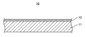
- FIG. 1 is a cross-sectional view schematically showing a laminated film according to this embodiment.
- the laminated film 10 includes a transparent support base material 11 and a coating layer 12 arranged on one of the main surfaces thereof.
- the laminated film according to this embodiment has, for example, a coating step of applying an active energy ray-curable resin composition to at least one main surface of a transparent support base material, and 5 mJ / J / to the resin composition. It is produced by a method comprising a first irradiation step of irradiating an active energy ray of cm 2 or more and 150 mJ / cm 2 or less to obtain a coating layer formed of a semi-cured resin composition.
- FIG. 2 is a flowchart showing a method for manufacturing a laminated film according to the present embodiment.
- Coating step (S11) An active energy ray-curable resin composition (for example, the above resin composition HC) is applied to at least one main surface of the transparent supporting substrate. This forms an uncured coating layer.
- active energy ray-curable resin composition for example, the above resin composition HC
- the resin composition is prepared by a known method.
- the resin composition is prepared by mixing each component using a commonly used mixing device such as a paint shaker, a mixer, and a disper.
- the method for applying the resin composition is appropriately selected according to the properties of the resin composition and the like.
- the coating method include a dip coating method, an air knife coating method, a curtain coating method, a roller coating method, a bar coating method, a die coating method, an inkjet method, a gravure coating method or an extrusion coating method.
- the amount of the resin composition applied is not particularly limited.
- the resin composition is applied so that the thickness of the coating layer is more than 2 ⁇ m, for example, 3 ⁇ m or more and 20 ⁇ m or less.
- the coated resin composition may be dried.
- the drying step at least a part of the solvent component contained in the resin composition is removed, the handleability is improved, and the degree of curing is easily controlled.
- the drying conditions are not particularly limited, and are appropriately set according to the coating amount, the type of solvent, and the like.
- First irradiation step (S13) The resin composition is irradiated with active energy rays of 5 mJ / cm 2 or more and 150 mJ / cm 2 or less.
- the resin composition is in a semi-cured state, and the above-mentioned coating layer is obtained.
- the polymerization rate of the resin composition and thus the indentation hardness H of the coating layer can be controlled by the integrated light amount in the first irradiation step.
- the first irradiation step may be performed before the unevenness forming step described later, and may be before or after the preform step.
- Integrated light quantity in this step may be at 10 mJ / cm 2 or more, may be at 20 mJ / cm 2 or more. Integrated light quantity in this step may be at 130 mJ / cm 2 or less, may be at 100 mJ / cm 2 or less.
- the irradiation of the active energy rays may be performed from the coating layer side or the transparent support base material side. The irradiation of the active energy rays may be performed in an atmospheric atmosphere or in a nitrogen atmosphere.
- the indentation hardness HB 2000 is smaller than the indentation hardness HB 100. Further, the indentation hardness HB 2000 is 0.15 GPa or more and 0.35 GPa or less. Therefore, the coating layer has excellent formability. Therefore, a desired pattern can be imparted to the coating layer.
- the indentation hardness HB 100 is 0.30 GPa or more and 0.65 GPa or less. Therefore, the laminated film can be peeled off from the mold while the pattern of the mold transferred to the surface of the coating layer is maintained with high accuracy.
- the type of active energy ray is not particularly limited.
- the active energy ray is appropriately selected depending on the type of the polymerizable monomer or oligomer.
- the active energy ray is not particularly limited, and may be ionizing radiation such as ultraviolet rays, electron beams, ⁇ rays, ⁇ rays, and ⁇ rays. Of these, ultraviolet rays are preferable.
- Ultraviolet rays are irradiated using, for example, a high-pressure mercury lamp or an ultra-high pressure mercury lamp.
- a coating layer containing a plurality of layers (typically a semi-cured hard coat layer and a semi-cured optical interference layer) is formed by a laminating method or a coating method.
- the first irradiation step (3) may be performed a plurality of times.
- (Laminating method) In the laminating method, a plurality of layers formed on different substrates are bonded together according to the coating step (1).
- the drying step (2) is arbitrarily performed before the layers are bonded together.
- the first irradiation step (3) may be performed on each layer before the layers are bonded to each other, or may be performed collectively after the layers are bonded. According to the laminating method, multiphase flow is easily suppressed even between uncured layers.
- the resin composition forming another layer is applied onto the layer formed on the transparent supporting substrate according to the coating step (1).
- the drying step (2) is optionally performed before the other resin composition is applied.
- the first irradiation step (3) is performed on the layer formed on the transparent supporting substrate before the other resin composition is applied. After the application of the other resin composition, the first irradiation step (3) is performed on the other resin composition.
- FIG. 3 is a flowchart showing a method for manufacturing a laminated film according to the present embodiment.
- FIG. 3 shows an embodiment in which the first irradiation step is performed after the uncured hard coat layer and the uncured optical interference layer are laminated by the laminating method.
- the molded body according to the present embodiment includes the above-mentioned transparent support base material and a cured resin layer (coating layer after curing) arranged on at least one main surface of the transparent support base material.
- the main surface of the cured resin layer on the opposite side to the transparent supporting base material includes a first region in which irregularities are formed and a second region other than that. The first region and the second region are integrally formed.
- the pencil hardness on the surface of the cured resin layer is H or more.
- the molded body may have a three-dimensional shape (three-dimensional shape) as well as fine irregularities.
- the molded body is formed by partially imparting unevenness to the coating layer of the laminated film according to the present embodiment and curing it.
- the cured resin layer has the same physical characteristics as the coating layer irradiated with 1500 mJ / cm 2 active energy rays.
- the cured resin layer includes a first region in which fine irregularities are formed and a second region other than the first region. A plurality of first and / or second regions may be arranged.
- the cured resin layer may be one layer or may include two or more layers, and the cured resin layer includes at least a hard coat layer.
- the cured resin layer includes a hard coat layer and one or more functional layers (typically, a light interference layer).
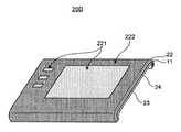
- the molded body is used, for example, as a protective material for a display.
- the first area is arranged so as to correspond to the display.
- the first region can be understood as the display portion of the molded body.
- the unevenness improves anti-glare properties.
- the first area may be arranged so as to correspond to the operation display unit.
- the second area is arranged so as to correspond to, for example, an area (bezel) surrounding the display.
- the second region can be understood as the bezel portion of the molded body.
- the second region has a texture different from that of the first region, for example, a glossy feeling. Therefore, the design of the bezel portion is improved.
- the first region and the second region are integrally formed. That is, both the first region and the second region are arranged on the surface of one cured resin layer. Therefore, a seamless design can be realized by using this molded body.
- the pencil hardness on the surface of the cured resin layer is H or higher. That is, the cured resin layer has a high hardness. Therefore, the molded product has excellent scratch resistance, and the unevenness is maintained for a long period of time.
- the pencil hardness on the surface of the cured resin layer is preferably 2H or more.
- the pencil hardness of the surface of the cured resin layer is measured in a region where unevenness is not imparted (for example, a second region). Alternatively, it is measured on the surface of a smooth cured resin layer without irregularities created for measurement.
- the height of the convex part is not particularly limited. From the viewpoint of anti-glare property, the height of the convex portion may be, for example, 0.3 ⁇ m or more and 4.0 ⁇ m or less, and may be 1.0 ⁇ m or more and 2.0 ⁇ m or less.
- the height of the convex portion is calculated from the cross section of the cured resin layer in the thickness direction.
- the height of the convex portion is an average value at any five points of the distance from the lowest point of the concave portion formed in the first region to the highest point of the convex portion.
- the ten-point average roughness Rz JIS of the first region is preferably 0.2 ⁇ m or more and 1.0 ⁇ m or less.
- the ten-point average roughness Rz JIS is determined in accordance with the provisions of JIS B0601; 2001, for example, using a laser microscope.
- the ten-point average roughness Rz JIS is specifically, in the roughness curve of the reference length obtained by applying the cutoff value phase compensation band passage filter, from the highest peak (convex part) to the fifth from the highest. It is the sum of the average of the mountain heights and the average of the valley depths from the deepest valley bottom (recess) to the fifth in the order of depth.
- the molded body may further include a decorative layer.
- the molded body includes, for example, a transparent support base material, a cured resin layer arranged on one main surface of the transparent support base material, and a decorative layer arranged on the other main surface of the transparent support base material. ..
- the decorative layer may be provided on a part of the other main surface of the transparent supporting substrate.
- the decorative layer is a layer that gives the molded body decoration such as a pattern, letters, or metallic luster.
- the decorative layer enhances the design of the molded product.
- the decorative layer is arranged, for example, so as to face the second region. At this time, the decorative layer is visually recognized through the second region.
- the decorative layer examples include at least one of a printing layer and a thin-film deposition layer.
- the print layer and the vapor deposition layer are each one or more layers, and may include a plurality of layers.
- the thickness of the decorative layer is not particularly limited, and is appropriately set according to the design and the like.
- the print layer is formed of, for example, a colored ink containing a binder resin and a colorant.
- the binder resin is not particularly limited.
- the binder resin include polyvinyl chloride resins such as vinyl chloride / vinyl acetate copolymers, polyamide resins, polyester resins, polyacrylic resins, polyurethane resins, polyvinyl acetal resins, polyester urethane resins, and celluloses. Examples thereof include ester-based resins, alkyd resins, and chlorinated polyolefin-based resins.
- the colorant is not particularly limited, and examples thereof include known pigments or dyes.
- the yellow pigment include azo pigments such as polyazo, organic pigments such as isoindolinone, and inorganic pigments such as titanium nickel antimon oxide.
- the red pigment include azo pigments such as polyazo, organic pigments such as quinacridone, and inorganic pigments such as valve stems.
- the blue pigment include organic pigments such as phthalocyanine blue and inorganic pigments such as cobalt blue.
- the black pigment include organic pigments such as aniline black.
- the white pigment include inorganic pigments such as titanium dioxide.
- the vapor deposition layer is formed of, for example, at least one metal selected from the group of aluminum, nickel, gold, platinum, chromium, iron, copper, indium, tin, silver, titanium, lead, zinc, etc., or an alloy or compound thereof. Will be done.
- the molded body may further include a molding resin layer.
- the molded resin layer supports the cured resin layer together with the transparent supporting base material.
- the molded body includes, for example, a transparent support base material, a cured resin layer arranged on one main surface of the transparent support base material, and a molding resin layer arranged on the other main surface of the transparent support base material. ..
- the shape of the molded resin layer is not limited. Therefore, the degree of freedom in designing the molded body is increased.
- the resin forming the molding resin layer is not particularly limited.
- the molded resin layer contains, for example, a thermosetting resin and / or a thermoplastic resin.
- the thermosetting resin include phenol resin, epoxy resin, melamine resin, urea resin, unsaturated polyester, and thermosetting polyimide.
- the thermoplastic resin include so-called engineering plastics. Examples of engineering plastics include polyamide, polyacetal, polycarbonate, ultra-high molecular weight polyethylene, polysulfone, polyether sulfone, polyphenylene sulfide, and liquid crystal polymer.
- the molded body includes a transparent support base material, a cured resin layer arranged on one main surface of the transparent support base material, a decorative layer arranged on the other main surface of the transparent support base material, and a molding resin layer. , May be provided.
- the decorative layer is arranged so as to be sandwiched between the cured resin layer and the molded resin layer, or is arranged on the surface of the molded resin layer opposite to the cured resin layer.
- the molded product is particularly suitable as a protective material for a display.
- the display include a liquid crystal display, an organic EL display, and a plasma display.
- the molded body is particularly suitable as a protective material for an in-vehicle touch panel display.
- the molded body is arranged so that the first region faces the information display portion of the display.
- the molded body is arranged so that the hard coat layer faces outward.
- the molded body is also particularly suitable as an instrument panel and / or a center cluster panel that also serves as a protective material for the display.
- FIG. 4 is a cross-sectional view schematically showing a molded body according to the present embodiment.
- the molded body 20A includes a transparent support base material 11 and a cured resin layer 22 arranged on one of the main surfaces thereof.
- the cured resin layer 22 includes a first region 221 having fine irregularities and a smooth second region 222.
- FIG. 5 is a cross-sectional view schematically showing another molded body according to the present embodiment.
- the molded body 20B includes a transparent support base material 11, a cured resin layer 22 arranged on one of the main surfaces thereof, a decorative layer 23, and a molded resin layer 24.
- the decorative layer 23 is arranged so as to face the second region 222 and to be sandwiched between the cured resin layer 22 and the molding resin layer 24.
- FIG. 6 is a cross-sectional view schematically showing another molded body according to the present embodiment.
- the molded body 20C includes a transparent support base material 11, a cured resin layer 22 arranged on one of the main surfaces thereof, a decorative layer 23, and a molded resin layer 24.
- the decorative layer 23 is arranged so as to face the second region 222 and on the side opposite to the cured resin layer 22 of the molding resin layer 24.
- FIG. 7 is a perspective view schematically showing still another molded body according to the present embodiment.
- the molded body 20D includes a transparent support base material 11, a cured resin layer 22 arranged on one of the main surfaces thereof, a decorative layer 23, and a molded resin layer 24.
- the molded body 20D has a three-dimensional shape.
- the molded body 20D is, for example, a protective material for a display of a car navigation system.
- the cured resin layer 22 includes a plurality of first regions 221 and a second region 222 surrounding the first regions 221.
- One first area 221 corresponds to the information display portion of the display, and the other first area 221 faces the operation display unit.
- the second area 222 corresponds to the bezel surrounding the display.
- the molded product according to the present embodiment is obtained by forming irregularities on the coating layer of the above-mentioned laminated film and then irradiating with active energy rays (second irradiation step). This makes it possible to simultaneously form a plurality of regions having different textures on the coating layer, for example, an uneven region and a smooth region.
- the coating layer is active energy ray-curable and can be obtained, for example, by performing the first irradiation step on the uncured resin composition.
- the molded body provided with the decorative layer is a laminated film, a laminated body having a transparent support base material and an uncured resin composition layer (hereinafter referred to as a precursor of a laminated film), or a molded body having a decorative layer. Obtained by forming.
- the step of forming the decorative layer may be performed before the first irradiation step or after the second irradiation step, and may be performed between the first irradiation step and the second irradiation step. May be done.
- a molded body having a three-dimensional shape can be obtained by injection molding a laminated film.
- the injection molding step is performed before, after, or in parallel with the unevenness forming step. Above all, it is preferable that the injection molding step and the unevenness forming step are performed in parallel, that is, the fine unevenness and the three-dimensional shape are formed in one step.
- the preform process be performed before the injection molding process.
- the laminated film or the precursor of the laminated film is formed in advance into a shape close to a three-dimensional shape. This makes it easier to obtain the desired three-dimensional shape in injection molding.
- the method for manufacturing the molded product includes a step of forming irregularities on the laminated film and a second irradiation step.
- FIG. 8 is a flowchart showing a method for manufacturing a molded product according to the present embodiment.
- the method for manufacturing the molded body includes a decoration step on the laminated film, a preform step, an unevenness forming step (and an injection molding step), and a second irradiation step.
- FIG. 9 is a flowchart showing a method of manufacturing a molded product according to the present embodiment.
- the method for producing the molded product includes a decoration step on the precursor of the laminated film, a preform step, a first irradiation step, an unevenness forming step (and an injection molding step), and a second irradiation step. , Equipped with.
- FIG. 10 is a flowchart showing a method for manufacturing a molded product according to the present embodiment. Hereinafter, each step will be described.
- the resin composition is semi-cured by the first irradiation step to form a coating layer.
- the indentation hardness H 100 of the coating layer is 0.30 GPa or more and 0.65 GPa or less.
- the indentation hardness HB 2000 of the coating layer is 0.15 GPa or more and 0.35 GPa or less.
- the indentation hardness HB 2000 is smaller than the indentation hardness HB 100.
- the method of forming the print layer is not particularly limited. Examples of the method for forming the print layer include an offset printing method, a gravure printing method, a screen printing method, a roll coating method, and a spray coating method.
- the method for forming the thin-film deposition layer is also not particularly limited. Examples of the method for forming the thin-film deposition layer include a vacuum vapor deposition method, a sputtering method, an ion plating method, and a plating method.
- Preform step (S24) In this step, a shape along a desired three-dimensional shape is formed on the laminated film or its precursor. After the preform step, a trimming step may be performed to remove unnecessary portions of the laminated film or its precursor.
- the preform method is not particularly limited.
- the preform is performed by, for example, a vacuum forming method, a compressed air forming method, or a vacuum forming method.
- the first mold and the laminated film or its precursor are installed in the same processing chamber.
- the laminated film or its precursor is installed so that the transparent supporting base material faces the first mold.
- the laminated film or its precursor is heated to a temperature equal to or higher than Tg of the resin composition to put the treatment chamber in a vacuum state and / or a pressurized state.
- Tg of the resin composition
- the laminated film or its precursor is deformed along the first mold.
- the laminated film or its precursor is then cooled and removed from the first mold.
- the material of the first mold is not particularly limited.
- the first mold may be made of resin or metal.
- the resin composition used in the preform process is in an uncured or semi-cured state. Therefore, the laminated film or its precursor can be easily deformed along the first mold without causing cracks. Therefore, a complicated three-dimensional shape is realized.
- the resin composition after the preform step is still in an uncured or semi-cured state.
- the indentation hardness HB 100 by the nanoindentation method at an indentation depth of 100 nm of the coating layer is 0.30 GPa or more and 0.65 GPa or less.
- the indentation hardness HB 2000 by the nanoindentation method at an indentation depth of 2000 nm of the coating layer is 0.15 GPa or more and 0.35 GPa or less.
- the indentation hardness HB 2000 is smaller than the indentation hardness HB 100. Therefore, the coating layer exhibits excellent releasability and formability.
- the material of the second mold is not particularly limited.
- the second mold may be made of resin or metal. Regardless of the material of the mold, the coating layer is easily stripped from the mold.
- a three-dimensional shape may be imparted along with the unevenness.
- a second mold having a desired three-dimensional shape as well as unevenness is used.
- the unevenness may be imparted by an injection molding method (for example, an insert molding method).
- injection molding for example, the coating layer is opposed to the second mold having partial irregularities, and the molding resin is injected toward the transparent support base material.
- unevenness is formed on a part of the coating layer, and a molding resin layer is formed on the other main surface of the transparent supporting base material.
- the laminated film has a semi-cured coating layer. Therefore, the laminated film can follow the molds having various shapes. Further, even when there is a dimensional difference between the three-dimensional shape formed by the preform and the second mold used in this step, the generation of cracks is suppressed.
- Second irradiation step (S22) In this step, the coating layer is irradiated with active energy rays. As a result, the coating layer is completely cured to form a cured resin layer.
- the active energy rays are irradiated so that the pencil hardness of the cured resin layer is H or higher, for example.
- Integrated light quantity of the active energy ray in the present step is 150 mJ / cm 2, such as more than, at 300 mJ / cm 2 or more 2000 mJ / cm 2 or less.
- an unevenness forming step is performed on a laminated film provided with a coating layer in a semi-cured state. Therefore, it is possible to impart fine unevenness to the laminated film with high accuracy. Further, the laminated film can be formed into various three-dimensional shapes without causing cracks. Then, after the unevenness forming step is completed, the resin composition is cured. Therefore, the imparted shape is retained for a long period of time.
- Acrylic polymers A and B were prepared as follows. [Preparation of acrylic polymer A] A mixture consisting of 30 parts of n-butyl methacrylate, 70 parts of methyl methacrylate and 0.8 parts of t-butylperoxy-2-ethylhexanoate was prepared. Separately, 40 parts of toluene was put into a 500 ml reaction vessel equipped with a stirring blade, a nitrogen introduction tube, a cooling tube and a dropping funnel, and heated to 110 ° C. While stirring the inside of the reaction vessel, the above mixture was added dropwise at a constant velocity over 2 hours under a nitrogen atmosphere. After completion of the dropping, the reaction was carried out for 1 hour under the temperature condition of 110 ° C.
- reaction vessel having the same shape as above, 306.5 parts of precursor B1, 15.66 parts of acrylic acid, 0.43 parts of hydroquinone monomethyl ether, 56 parts of toluene were charged, and air was blown into the reaction vessel to stir. While heating to 90 ° C. Under the temperature condition of 90 ° C., a mixed solution of 3 parts of toluene and 0.81 part of tetrabutylammonium bromide was further added to this reaction vessel, and the mixture was reacted for 1 hour. Subsequently, the mixture was heated to 105 ° C., and the reaction was carried out under the temperature condition of 105 ° C. until the acid value of the solid content in the reaction solution became 8 or less.
- KOH potassium hydroxide
- Example 1 (1) Preparation of Resin Composition HC1 In a container filled with propylene glycol monomethyl ether, 37 parts of acrylic polymer A, 35 parts of Aronix M-402, 12 parts of purple light UV-AF305A, and 15 parts of ELCOM V-8802. 2.9 parts for a total of 100 parts of the above resin component and ELCOM V-8802, and 3.9 parts of Omnirad TPO H for a total of 100 parts of the above resin component and ELCOM V-8802. The parts were mixed to produce a transparent resin composition HC1 having a solid content concentration of 35%.
- Print layer is formed by screen printing on the main surface of the produced laminated film 1 opposite to the coating layer of the transparent support base material, and the drying temperature is increased. It was dried at 80 ° C. for 10 minutes. This printing step was repeated 5 times and then dried at 90 ° C. for 1 hour. Aniline black was used to form the print layer.
- the coating layer was irradiated with active energy rays (ultraviolet rays) having an integrated light amount of 1500 mJ / cm 2.
- active energy rays ultraviolet rays
- the transparent support base material, the cured resin layer (hard coat layer) arranged on one main surface of the transparent support base material, and the printing layer arranged on the other main surface of the transparent support base material are molded.
- a molded product X1 comprising a resin layer was obtained.
- the surface of the cured resin layer had a first region formed by transferring the unevenness of the mold and a smooth second region.
- (B) Formability The first region of the cured resin layer of the molded product was visually observed and evaluated according to the following criteria. Best: Sufficient anti-glare property is obtained, and it can be judged that the height of the convex part is 80% or more of the maximum height of the convex part of the mold. Good: Sufficient anti-glare property is obtained for practical use. , It can be judged that the height of the convex part is 50% or more and less than 80% of the maximum height of the convex part of the mold. It can be judged that it is less than 50% of the maximum height of the part.
- a minute AC load was superposed on the surface of the laminated film on a quasi-static test load. The load was applied until the maximum load of 50 mN was reached.
- As an indenter a Berkovich-type diamond indenter (tip radius of curvature of 20 nm) was used. The continuous stiffness with respect to the depth was calculated from the vibration component of the generated displacement and the phase difference between the displacement and the load, and the hardness profile with respect to the depth was obtained. The hardness at a depth of 100 nm in this profile was defined as the indentation hardness HB 100 , and the hardness at 2000 nm was defined as the indentation hardness HB 2000 .
- IMicro dedicated software was used to calculate the load and stiffness.
- the Poisson's ratio of the coating layer was set to 0.35.
- the load was controlled so that the strain rate ( ⁇ P / ⁇ t) / P was 0.2.
- the point tentatively defined on the iMicro dedicated software at the time of measurement was set as it is as the surface position of the coating layer. ..
- the elongation rate when a crack of the above size was first confirmed was defined as the elongation rate of the laminated film.
- Three test pieces were prepared from the same laminated film, and the average value of the elongation rates calculated for each was taken as the elongation rate of the laminated film.
- Pencil hardness JIS K 5600-5-4 (1999) The pencil hardness in the second region of the cured resin layer of the molded product was measured according to the scratch hardness (pencil method).
- Example 2 In the preparation of the laminated film (2), the laminated film A2 was obtained in the same manner as in Example 1 except that the film thickness of the coating layer was set to 6 ⁇ m. Using the laminated film A2, a molded product X2 was obtained in the same manner as in Example 1. The laminated film A2 and the molded product X2 were evaluated as described above. The results are shown in Table 1.
- Example 3 In the preparation of the laminated film (2), the laminated film A3 was obtained in the same manner as in Example 1 except that the film thickness of the coating layer was set to 10 ⁇ m. Using the laminated film A3, a molded product X3 was obtained in the same manner as in Example 1. The laminated film A3 and the molded product X3 were evaluated as described above. The results are shown in Table 1.
- Example 4 In the preparation of the laminated film (2), the laminated film A4 was obtained in the same manner as in Example 1 except that the active energy rays were irradiated in a nitrogen atmosphere. Using the laminated film A4, a molded product X4 was obtained in the same manner as in Example 1. The laminated film A4 and the molded product X4 were evaluated as described above. The results are shown in Table 1.
- Example 5 In the preparation of the laminated film (2), the laminated film A5 was obtained in the same manner as in Example 1 except that the active energy rays were irradiated so that the integrated light amount was 7.5 mJ / cm 2. Using the laminated film A5, a molded product X5 was obtained in the same manner as in Example 1. The laminated film A5 and the molded product X5 were evaluated as described above. The results are shown in Table 1.
- Example 6 In the preparation of the laminated film (2), the laminated film A6 was obtained in the same manner as in Example 1 except that the active energy rays were irradiated so that the integrated light amount was 100 mJ / cm 2. Using the laminated film A6, a molded product X6 was obtained in the same manner as in Example 1. The laminated film A6 and the molded product X6 were evaluated as described above. The results are shown in Table 1.
- Example 1 A laminated film B1 was obtained in the same manner as in Example 1 except that the laminated film was not irradiated with active energy rays in the preparation (2). Using the laminated film B1, a molded body Y1 was obtained in the same manner as in Example 1. The laminated film B1 and the molded body Y1 were evaluated as described above. The results are shown in Table 1.
- Example 2 In the preparation of the laminated film (2), the laminated film B2 was obtained in the same manner as in Example 1 except that the active energy rays were irradiated so that the integrated light amount was 200 mJ / cm 2. Using the laminated film B2, a molded product Y2 was obtained in the same manner as in Example 1. The laminated film B2 and the molded body Y2 were evaluated as described above. The results are shown in Table 1.
- Example 3 In the preparation of the laminated film (2), the laminated film B3 was obtained in the same manner as in Example 1 except that the active energy rays were irradiated so that the integrated light amount was 500 mJ / cm 2. Using the laminated film B3, a molded product Y3 was obtained in the same manner as in Example 1. The laminated film B3 and the molded body Y3 were evaluated as described above. The results are shown in Table 1.
- Example 4 In the preparation of the laminated film (2), the laminated film B4 was obtained in the same manner as in Example 1 except that the active energy rays were irradiated so that the integrated light amount was 1500 mJ / cm 2. Using the laminated film B4, a molded product Y4 was obtained in the same manner as in Example 1. The laminated film B4 and the molded body Y4 were evaluated as described above. The results are shown in Table 1.
- Comparative Example 1 is an example in which the indentation hardness HB 100 and the indentation hardness HB 2000 are both small. In this example, the releasability and formability are low.
- Comparative Examples 2 to 4 are examples in which the indentation hardness HB 2000 is large. Even in these examples, the formability is low. In Comparative Example 3 and Comparative Example 4, the shape retention was also low.
- Example 7 (1) Preparation of Resin Composition HC2 In a container containing propylene glycol monomethyl ether, 43 parts of acrylic polymer A, 42 parts of Aronix M-402, 15 parts of ELCOM V-8802, and Omnirad 184 are the above resin components and ELCOM V. 2.9 parts for a total of 100 parts of -8802 and 3.9 parts of Omnirad TPO H for a total of 100 parts of the above resin component and ELCOM V-8802 were mixed to obtain a solid content concentration of 35%. A transparent resin composition HC2 was produced.
- Example 8 (1) Preparation of Resin Composition HC3 In a container containing propylene glycol monomethyl ether, 51 parts of acrylic polymer A, 49 parts of Aronix M-402, 2.9 parts of Omnirad 184 with respect to 100 parts of the above resin component, Omnirad. 3.9 parts of TPO H was mixed with a total of 100 parts of the above resin components to produce a transparent resin composition HC3 having a solid content concentration of 35%.
- Example 9 (1) Preparation of resin composition HC4 In a container containing propylene glycol monomethyl ether, 73 parts of n-acrylic polymer B, 12 parts of purple light UV-AF305A, 15 parts of ELCOM V-8802, and Omnirad 184 are the above resin components and ELCOM. 2.9 parts for a total of 100 parts with V-8802 and 3.9 parts for a total of 100 parts with the above resin component and ELCOM V-8802 were mixed, and the solid content concentration was 35%. The transparent resin composition HC4 of the above was produced.
- Example 10 (1) Preparation of Resin Composition HC5 In a container containing propylene glycol monomethyl ether, 85 parts of acrylic polymer B, 15 parts of ELCOM V-8802, and Omnirad 184 in a total of 100 parts of the above resin component and ELCOM V-8802. On the other hand, 2.9 parts and 3.9 parts of Omnirad TPO H were mixed with 100 parts in total of the above resin component and ELCOM V-8802 to produce a transparent resin composition HC5 having a solid content concentration of 35%. bottom.
- Example 11 (1) Preparation of Resin Composition HC6 In a container containing propylene glycol monomethyl ether, 100 parts of acrylic polymer B, 2.9 parts of Omnirad 184 with respect to 100 parts of the above resin component, and 100 parts of Omnirad TPO H with respect to the above resin component 100. 3.9 parts were mixed with respect to the parts to produce a transparent resin composition HC6 having a solid content concentration of 35%.
- Example 12 (1) Preparation of Resin Composition HC7 In a container containing propylene glycol monomethyl ether, 67.5 parts of CN-9893, 22.5 parts of Aronix M-315, 5.0 parts of Art Resin H-7M40, and Art Resin 5.0 parts of UN-904M, 2.9 parts of Omnirad 184 with respect to 100 parts of the above resin component, and 3.9 parts of Omnirad TPO H with respect to 100 parts of the above resin component were mixed, and the solid content concentration was 35. %% Transparent resin composition HC7 was produced.
- Example 13 (1) Preparation of Resin Composition HC8 In a container containing propylene glycol monomethyl ether, 50 parts of Art Resin H-7M40, 50 parts of Art Resin UN-904M, and Omnirad 184 are 2.9 with respect to 100 parts of the above resin component. 3.9 parts of Omnirad TPO H was mixed with 100 parts of the above resin component to produce a transparent resin composition HC8 having a solid content concentration of 35%.
- Comparative Example 5 is an example in which the indentation hardness HB 2000 is excessively large. In this example, the formability is low. In addition, the shape retention was low. Comparative Example 6 is an example in which the indentation hardness HB 2000 is large. In this example, the formability is low.
- Example 14 (1) Preparation of Resin Composition LR In a container containing propylene glycol monomethyl ether, 14.8 parts by mass of acrylic polymer A, 10 parts by mass of Aronix M-402, 13.3 parts by mass of KRM-8452, and so on. 13.3 parts by mass of purple light UV-AF305A and 4.8 parts by mass of Polymerd 184 were mixed. Further, the thru rear 4320 was mixed in an amount of 43.8 parts by mass. Thereby, a milky white resin composition LR for a low refractive index layer having a solid content concentration of 3% was prepared. The refractive index of the layer formed by the resin composition LR was 1.20 or more and 1.55 or less.
- Example 15 (1) Adjustment of Resin Composition HR In a container containing propylene glycol monomethyl ether, 8.9 parts by mass of acrylic polymer A, 2.7 parts by mass of KRM-8452, and 1.8 parts by mass of Omnirad 184 were added. , Mixed. Further, 86.5 parts by mass of HX-204 IP was mixed. Thereby, a milky white resin composition HR for a high refractive index layer having a solid content concentration of 3% was prepared. The refractive index of the layer formed by the resin composition HR was more than 1.55 and 2.00 or less.
- the protective film of the transfer film C-2 was peeled off to expose the uncured high refractive index layer.
- the low refractive index layer of the transfer film C-1 was bonded to the high refractive index layer.
- the protective film was peeled off, and the laminated body was irradiated with active energy rays (ultraviolet rays) having an integrated light amount of 35 mJ / cm 2.
- active energy rays ultraviolet rays
- Examples 14 and 15 the visual reflectance of the obtained molded product was also evaluated.
- (H) Visual reflectance A black paint (product name: CZ-805 BLACK (manufactured by Nikko Bics Co., Ltd.)) is applied to the surface of the transparent support base material of the laminated film opposite to the hard coat layer using a bar coater. The film was applied so that the dry film thickness was 3 ⁇ m or more and 6 ⁇ m or less. Next, the laminated film coated with the black paint was left to stand in a room temperature environment for 5 hours to dry. Subsequently, the integrated light amount was 1500 mJ / cm 2. A cured evaluation sample was prepared by irradiating with active energy rays of.
- the visual reflectance by the SCI method was measured and evaluated from the optical interference layer side of the evaluation sample.
- SD7000 manufactured by Nippon Denshoku Kogyo Co., Ltd. was used for the measurement, and the measurement wavelength region was set to 380 nm or more and 780 nm or less.
- Both the molded bodies of Examples 14 and 15 are excellent in releasability, shapeability and shape retention. Furthermore, no visible cracks could be confirmed in these molded bodies. In addition, it can be seen that the molded product has a small visual reflectance and has excellent antireflection performance.
- this laminated film is particularly preferably used for producing a protective material for a display having a seamless design.
Abstract
The present invention provides a multilayer film which has excellent shapability and excellent releasability from a mold. A multilayer film according to the present invention, which is provided with a transparent supporting base material and a coating layer that is arranged on at least one main surface of the transparent supporting base material, wherein: the coating layer contains an active energy ray-curable resin composition; the coating layer has a thickness of more than 2 μm; the coating layer has an indentation hardness HB100 of from 0.30 GPa to 0.65 GPa at an indentation depth of 100 nm as determined by a nanoindentation method; the coating layer has an indentation hardness HB2000 of from 0.15 GPa to 0.35 GPa at an indentation depth of 2,000 nm as determined by a nanoindentation method; and the indentation hardness HB2000 is lower than the indentation hardness HB100.
Description
本発明は、積層フィルムおよび成形体、ならびにこれらの製造方法に関する。
The present invention relates to a laminated film and a molded product, and a method for producing these.
ディスプレイは、コンピュータ、テレビジョン、携帯電話、携帯情報端末機器(タブレットパソコン、モバイル機器および電子手帳など)、車載機器など、様々な電装部品に使用されている。
The display is used for various electrical components such as computers, televisions, mobile phones, personal digital assistants (tablet personal computers, mobile devices, electronic organizers, etc.), in-vehicle devices, and the like.
ディスプレイの情報表示部分は、通常、保護材によって保護されている。保護材には、アンチグレア(anti-glare)性向上のために微細な凹凸が設けられる場合がある。特許文献1には、高さが100nm以上250nm以下の凸部を備えるフィルムが開示されている。
The information display part of the display is usually protected by a protective material. The protective material may be provided with fine irregularities in order to improve anti-glare properties. Patent Document 1 discloses a film having a convex portion having a height of 100 nm or more and 250 nm or less.
近年、保護材には、質感等の表面性状が異なる複数の領域が継ぎ目なく形成されたデザイン(以下、シームレスデザインと称す。)、例えばディスプレイの情報表示部分とその周囲を囲むベゼル部分とが一体的に形成されたデザインが求められている。しかし、特許文献1に記載されているフィルムを用いて、シームレスデザインを実現することは困難である。本発明の課題は、シームレスデザインを実現するのに適した、賦形性および金型からの離型性に優れる積層フィルムを提供することにある。
In recent years, the protective material has a design in which a plurality of areas having different surface textures such as textures are seamlessly formed (hereinafter referred to as seamless design), for example, an information display part of a display and a bezel part surrounding the information display part are integrated. There is a need for a specifically formed design. However, it is difficult to realize a seamless design by using the film described in Patent Document 1. An object of the present invention is to provide a laminated film having excellent shapeability and mold releasability, which is suitable for realizing a seamless design.
上記課題を解決するため、本発明は下記態様を提供する。
[1]
透明支持基材と、
前記透明支持基材の少なくとも一方の主面に配置されたコーティング層と、を備え、
前記コーティング層は、活性エネルギー線硬化性の樹脂組成物を含み、
前記コーティング層の厚さは、2μm超であり、
前記コーティング層の押し込み深度100nmにおけるナノインデンテーション法による押し込み硬さHB100は、0.30GPa以上0.65GPa以下であり、
前記コーティング層の押し込み深度2000nmにおけるナノインデンテーション法による押し込み硬さHB2000は、0.15GPa以上0.35GPa以下であり、
前記押し込み硬さHB2000は、前記押し込み硬さHB100より小さい、積層フィルム。 In order to solve the above problems, the present invention provides the following aspects.
[1]
With a transparent support base material,
A coating layer disposed on at least one main surface of the transparent support substrate.
The coating layer contains an active energy ray-curable resin composition and contains.
The thickness of the coating layer is more than 2 μm.
The indentation hardness HB 100 by the nanoindentation method at an indentation depth of 100 nm of the coating layer is 0.30 GPa or more and 0.65 GPa or less.
The indentation hardness HB 2000 by the nanoindentation method at an indentation depth of 2000 nm of the coating layer is 0.15 GPa or more and 0.35 GPa or less.
The indentation hardness HB 2000 is a laminated film smaller than the indentation hardness HB 100.
[1]
透明支持基材と、
前記透明支持基材の少なくとも一方の主面に配置されたコーティング層と、を備え、
前記コーティング層は、活性エネルギー線硬化性の樹脂組成物を含み、
前記コーティング層の厚さは、2μm超であり、
前記コーティング層の押し込み深度100nmにおけるナノインデンテーション法による押し込み硬さHB100は、0.30GPa以上0.65GPa以下であり、
前記コーティング層の押し込み深度2000nmにおけるナノインデンテーション法による押し込み硬さHB2000は、0.15GPa以上0.35GPa以下であり、
前記押し込み硬さHB2000は、前記押し込み硬さHB100より小さい、積層フィルム。 In order to solve the above problems, the present invention provides the following aspects.
[1]
With a transparent support base material,
A coating layer disposed on at least one main surface of the transparent support substrate.
The coating layer contains an active energy ray-curable resin composition and contains.
The thickness of the coating layer is more than 2 μm.
The indentation hardness HB 100 by the nanoindentation method at an indentation depth of 100 nm of the coating layer is 0.30 GPa or more and 0.65 GPa or less.
The indentation hardness HB 2000 by the nanoindentation method at an indentation depth of 2000 nm of the coating layer is 0.15 GPa or more and 0.35 GPa or less.
The indentation hardness HB 2000 is a laminated film smaller than the indentation hardness HB 100.
[2]
前記樹脂組成物の重合率PBと、活性エネルギー線を1500mJ/cm2照射した後の前記コーティング層における前記樹脂組成物の重合率PAとの差は、15%以上である、上記[1]に記載の積層フィルム。 [2]
The difference between the polymerization rate PB of the resin composition and the polymerization rate PA of the resin composition in the coating layer after irradiation with active energy rays at 1500 mJ / cm 2 is 15% or more, according to the above [1]. The laminated film described.
[3]
活性エネルギー線を1500mJ/cm2照射した後の前記コーティング層表面の鉛筆硬度は、H以上である、上記[1]または[2]に記載の積層フィルム。 [3]
The laminated film according to the above [1] or [2], wherein the pencil hardness of the surface of the coating layer after irradiation with active energy rays at 1500 mJ / cm 2 is H or more.
活性エネルギー線を1500mJ/cm2照射した後の前記コーティング層表面の鉛筆硬度は、H以上である、上記[1]または[2]に記載の積層フィルム。 [3]
The laminated film according to the above [1] or [2], wherein the pencil hardness of the surface of the coating layer after irradiation with active energy rays at 1500 mJ / cm 2 is H or more.
[4]
160℃における伸張率は、5%以上である、上記[1]~[3]のいずれかに記載の積層フィルム。 [4]
The laminated film according to any one of the above [1] to [3], wherein the elongation rate at 160 ° C. is 5% or more.
160℃における伸張率は、5%以上である、上記[1]~[3]のいずれかに記載の積層フィルム。 [4]
The laminated film according to any one of the above [1] to [3], wherein the elongation rate at 160 ° C. is 5% or more.
[5]
前記コーティング層の厚さは、3μm以上20μm以下である、上記[1]~[4]のいずれかに記載の積層フィルム。 [5]
The laminated film according to any one of the above [1] to [4], wherein the thickness of the coating layer is 3 μm or more and 20 μm or less.
前記コーティング層の厚さは、3μm以上20μm以下である、上記[1]~[4]のいずれかに記載の積層フィルム。 [5]
The laminated film according to any one of the above [1] to [4], wherein the thickness of the coating layer is 3 μm or more and 20 μm or less.
[6]
前記透明支持基材の厚さは、75μm以上500μm以下である、上記[1]~[5]のいずれかに記載の積層フィルム。 [6]
The laminated film according to any one of the above [1] to [5], wherein the thickness of the transparent supporting base material is 75 μm or more and 500 μm or less.
前記透明支持基材の厚さは、75μm以上500μm以下である、上記[1]~[5]のいずれかに記載の積層フィルム。 [6]
The laminated film according to any one of the above [1] to [5], wherein the thickness of the transparent supporting base material is 75 μm or more and 500 μm or less.
[7]
透明支持基材の少なくとも一方の主面に、活性エネルギー線硬化性の樹脂組成物を塗布する塗布工程と、
前記樹脂組成物に5mJ/cm2以上150mJ/cm2以下の活性エネルギー線を照射して、コーティング層を得る第1照射工程と、を備え、
前記コーティング層の厚さは、2μm超であり、
前記コーティング層の押し込み深度100nmにおけるナノインデンテーション法による押し込み硬さHB100は、0.30GPa以上0.65GPa以下であり、
前記コーティング層の押し込み深度2000nmにおけるナノインデンテーション法による押し込み硬さHB2000は、0.15GPa以上0.35GPa以下であり、
前記押し込み硬さHB2000は、前記押し込み硬さHB100より小さい、積層フィルムの製造方法。 [7]
A coating step of applying an active energy ray-curable resin composition to at least one main surface of the transparent supporting substrate, and
The resin composition is provided with a first irradiation step of irradiating the resin composition with active energy rays of 5 mJ / cm 2 or more and 150 mJ / cm 2 or less to obtain a coating layer.
The thickness of the coating layer is more than 2 μm.
The indentation hardness HB 100 by the nanoindentation method at an indentation depth of 100 nm of the coating layer is 0.30 GPa or more and 0.65 GPa or less.
The indentation hardness HB 2000 by the nanoindentation method at an indentation depth of 2000 nm of the coating layer is 0.15 GPa or more and 0.35 GPa or less.
The indentation hardness HB 2000 is a method for producing a laminated film, which is smaller than the indentation hardness HB 100.
[8]
透明支持基材と、
前記透明支持基材の少なくとも一方の主面に配置された硬化樹脂層と、を備え、
前記硬化樹脂層の前記透明支持基材とは反対側の主面は、凹凸が形成された第1領域とそれ以外の第2領域とを備え、
前記第1領域と前記第2領域とは、一体的に形成されており、
前記硬化樹脂層表面の鉛筆硬度は、H以上である、成形体。 [8]
With a transparent support base material,
A cured resin layer disposed on at least one main surface of the transparent support substrate.
The main surface of the cured resin layer on the opposite side of the transparent supporting base material includes a first region in which irregularities are formed and a second region other than that.
The first region and the second region are integrally formed.
A molded product having a pencil hardness on the surface of the cured resin layer of H or higher.
[9]
前記硬化樹脂層は、前記透明支持基材の一方の主面に配置されており、
さらに、前記透明支持基材の他方の主面に配置された加飾層を備える、上記[8]に記載の成形体。 [9]
The cured resin layer is arranged on one main surface of the transparent supporting base material, and is arranged on one main surface.
The molded product according to the above [8], further comprising a decorative layer arranged on the other main surface of the transparent support base material.
[10]
前記硬化樹脂層は、前記透明支持基材の一方の主面に配置されており、
さらに、前記透明支持基材の他方の主面に配置された成形樹脂層を備える、上記[8]または[9]に記載の成形体。 [10]
The cured resin layer is arranged on one main surface of the transparent supporting base material, and is arranged on one main surface.
The molded product according to the above [8] or [9], further comprising a molding resin layer arranged on the other main surface of the transparent supporting base material.
[11]
請求項1~6のいずれか一項に記載の積層フィルムの前記コーティング層を、凹凸を有する金型に接触させて、前記コーティング層の一部に凹凸を形成する凹凸形成工程と、
前記凹凸形成工程の後、前記コーティング層に活性エネルギー線を照射して、硬化樹脂層を得る第2照射工程と、を備える、成形体の製造方法。 [11]
The unevenness forming step of contacting the coating layer of the laminated film according to any one of claims 1 to 6 with a mold having unevenness to form unevenness on a part of the coating layer.
A method for producing a molded product, comprising a second irradiation step of irradiating the coating layer with active energy rays to obtain a cured resin layer after the unevenness forming step.
[12]
前記第2照射工程では、硬化後の前記コーティング層表面の鉛筆硬度がH以上になるように、前記活性エネルギー線が照射される、上記[11]に記載の成形体の製造方法。 [12]
The method for producing a molded product according to the above [11], wherein in the second irradiation step, the active energy rays are irradiated so that the pencil hardness of the surface of the coating layer after curing becomes H or more.
[13]
前記積層フィルムにおいて、前記コーティング層は前記透明支持基材の一方の主面に配置されており、
前記透明支持基材の他方の主面に、加飾層が配置されている、上記[11]または[12]に記載の成形体の製造方法。 [13]
In the laminated film, the coating layer is arranged on one main surface of the transparent supporting base material.
The method for producing a molded product according to the above [11] or [12], wherein the decorative layer is arranged on the other main surface of the transparent support base material.
[14]
前記積層フィルムにおいて、前記コーティング層は前記透明支持基材の一方の主面に配置されており、
前記凹凸形成工程では、前記金型に前記コーティング層を対向させるとともに、前記透明支持基材に向かって成形用樹脂を射出して、前記コーティング層に前記凹凸とともに成形樹脂層が形成される、上記[11]~[13]のいずれかに記載の成形体の製造方法。 [14]
In the laminated film, the coating layer is arranged on one main surface of the transparent supporting base material.
In the unevenness forming step, the coating layer is opposed to the mold, and the molding resin is injected toward the transparent support base material to form the molding resin layer together with the unevenness on the coating layer. The method for producing a molded product according to any one of [11] to [13].
[15]
前記金型は、前記積層フィルムに立体形状を付与し、
さらに、前記準備工程の後、前記凹凸形成工程の前に、前記積層フィルムを前記立体形状に沿った形状に成形するプレフォーム工程を備える、上記[14]に記載の成形体の製造方法。 [15]
The mold imparts a three-dimensional shape to the laminated film and gives the laminated film a three-dimensional shape.
The method for producing a molded product according to the above [14], further comprising a preform step of molding the laminated film into a shape along the three-dimensional shape after the preparation step and before the unevenness forming step.
本発明によれば、賦形性および金型からの離型性に優れる積層フィルムを提供することができる。
According to the present invention, it is possible to provide a laminated film having excellent shapeability and mold releasability.
保護材の最外には、通常、硬化樹脂を含む層(以下、硬化樹脂層と称す場合がある。)が配置される。シームレスデザインを実現するためには、この硬化樹脂層に、例えば、ディスプレイの情報表示部分に対応する領域とベゼルに対応する領域とが、一体的に形成される必要がある。すなわち、硬化樹脂層の表面に、凹凸を備える領域と、これとは異なる質感(テクスチャー)、例えばつや感を有する領域とが形成されなければならない。しかし、硬い硬化樹脂層に凹凸を付与するのは困難である。そこで、樹脂を完全に硬化させる前に、凹凸を形成することが考えられる。
A layer containing a cured resin (hereinafter, may be referred to as a cured resin layer) is usually arranged on the outermost side of the protective material. In order to realize a seamless design, for example, a region corresponding to an information display portion of a display and a region corresponding to a bezel need to be integrally formed on this cured resin layer. That is, on the surface of the cured resin layer, a region having unevenness and a region having a different texture (texture), for example, a glossy feeling must be formed. However, it is difficult to impart unevenness to the hard cured resin layer. Therefore, it is conceivable to form irregularities before the resin is completely cured.
凹凸を備える領域およびこれとは異なる質感を有する領域は、例えば、完全未硬化でも完全硬化でもない硬化樹脂層(コーティング層)に、凹凸部と平坦部とを有する金型を押し当てることにより形成される。コーティング層のタック性が大きいと、金型から剥離する際、特に平坦部に密着していたコーティング層の表面が荒れたり白化したりして、所望の質感が得られ難い。コーティング層のタック性は、表面近傍におけるコーティング層の硬度に影響される。
The region having unevenness and the region having a texture different from this are formed by, for example, pressing a mold having an uneven portion and a flat portion against a cured resin layer (coating layer) that is neither completely uncured nor completely cured. Will be done. If the tackiness of the coating layer is large, the surface of the coating layer, which is particularly in close contact with the flat portion, becomes rough or whitened when peeled from the mold, and it is difficult to obtain a desired texture. The tackiness of the coating layer is affected by the hardness of the coating layer in the vicinity of the surface.
一方、凹凸の形成し易さは、コーティング層の内部における硬度に影響される。例えば、コーティング層の内部における硬度が過度に低いと復元率が高くなり、凹凸が形成され難くなる。特に、付与される凸部の高さと同程度コーティング層の内部の位置における硬度が、凹凸の形成し易さに大きな影響を与える。
On the other hand, the ease of forming irregularities is affected by the hardness inside the coating layer. For example, if the hardness inside the coating layer is excessively low, the restoration rate becomes high and unevenness is difficult to form. In particular, the hardness at the internal position of the coating layer to the same extent as the height of the applied convex portion has a great influence on the easiness of forming the unevenness.
本実施形態は、コーティング層の表面近傍および内部の硬度に着目し、これらが特定の範囲および関係を満たすコーティング層を備える積層フィルムを提供する。このようなコーティング層は、完全未硬化でも完全硬化でもない。そのため、コーティング層には、凹凸が転写され得る硬度と、金型から容易に剥離され得る低タック性とが兼備される。よって、コーティング層に異なる質感を有する複数の領域、例えば凹凸領域と平滑な領域とを同時に形成することができる。さらに、立体形状に成形される(例えば、プレフォームされる)コーティング層を未硬化あるいは半硬化状態にできるため、伸び易い。よって、積層フィルムを複雑な立体形状に成形することも可能である。加えて、凹凸、さらに必要に応じて立体形状を付与した後、コーティング層を完全に硬化させることにより、これらの形状は長期的に保持される。
The present embodiment focuses on the hardness near and inside the surface of the coating layer, and provides a laminated film having a coating layer in which these satisfy a specific range and relationship. Such a coating layer is neither completely uncured nor completely cured. Therefore, the coating layer has both hardness that allows unevenness to be transferred and low tackiness that can be easily peeled off from the mold. Therefore, it is possible to simultaneously form a plurality of regions having different textures on the coating layer, for example, an uneven region and a smooth region. Further, since the coating layer formed into a three-dimensional shape (for example, preformed) can be uncured or semi-cured, it is easy to stretch. Therefore, it is also possible to form the laminated film into a complicated three-dimensional shape. In addition, these shapes are retained for a long period of time by completely curing the coating layer after imparting irregularities and, if necessary, three-dimensional shapes.
本実施形態に係る積層フィルムを用いることにより、シームレスデザインが実現される。すなわち、本実施形態に係る積層フィルムは、シームレスデザインを有する成形体の材料として適している。近年、例えば車載用途においては、ベゼル部分をインストルメントパネルおよび/またはセンタークラスターパネルを兼ねるまで拡大したようなシームレスデザインを有するパネルも提案されている。このようなパネルは、非常に大きく、また複雑な立体形状を有している。本実施形態に係る積層フィルムは、特に、上記のようなシームレスデザインを有する大型の成形体の材料として適している。
A seamless design is realized by using the laminated film according to this embodiment. That is, the laminated film according to this embodiment is suitable as a material for a molded product having a seamless design. In recent years, for example, in in-vehicle applications, panels having a seamless design in which the bezel portion is expanded to serve as an instrument panel and / or a center cluster panel have also been proposed. Such panels are very large and have a complex three-dimensional shape. The laminated film according to the present embodiment is particularly suitable as a material for a large molded body having the above-mentioned seamless design.
積層フィルム
本実施形態に係る積層フィルムは、透明支持基材と、透明支持基材の少なくとも一方の主面に配置されたコーティング層と、を備える。コーティング層の厚さは、2μm超である。コーティング層は、活性エネルギー線硬化性の樹脂組成物を含む。 Laminated Film The laminated film according to the present embodiment includes a transparent support base material and a coating layer arranged on at least one main surface of the transparent support base material. The thickness of the coating layer is more than 2 μm. The coating layer contains an active energy ray-curable resin composition.
本実施形態に係る積層フィルムは、透明支持基材と、透明支持基材の少なくとも一方の主面に配置されたコーティング層と、を備える。コーティング層の厚さは、2μm超である。コーティング層は、活性エネルギー線硬化性の樹脂組成物を含む。 Laminated Film The laminated film according to the present embodiment includes a transparent support base material and a coating layer arranged on at least one main surface of the transparent support base material. The thickness of the coating layer is more than 2 μm. The coating layer contains an active energy ray-curable resin composition.
(押し込み硬さ)
コーティング層の押し込み深度100nmにおけるナノインデンテーション法による押し込み硬さHB100は、0.30GPa以上0.65GPa以下である。コーティング層の押し込み深度2000nmにおけるナノインデンテーション法による押し込み硬さHB2000は、0.15GPa以上0.35GPa以下である。押し込み硬さHB2000は、押し込み硬さHB100より小さい。このようなコーティング層は、完全未硬化でも完全硬化でもない状態(以下、半硬化あるいは半硬化状態と称する。)であるといえる。 (Pushing hardness)
The indentation hardness HB 100 by the nanoindentation method at an indentation depth of 100 nm of the coating layer is 0.30 GPa or more and 0.65 GPa or less. The indentation hardness HB 2000 by the nanoindentation method at an indentation depth of 2000 nm of the coating layer is 0.15 GPa or more and 0.35 GPa or less. The indentation hardness HB 2000 is smaller than the indentation hardness HB 100. It can be said that such a coating layer is in a state of neither completely uncured nor completely cured (hereinafter, referred to as semi-cured or semi-cured state).
押し込み硬さHB100は、コーティング層の表面近傍における硬度(以下、表面硬度と称する場合がある。)を示している。押し込み硬さHB2000は、コーティング層の内部における硬度(以下、内部硬度と称する場合がある。)を示している。コーティング層の内部とは、コーティング層の透明支持基材側の領域である。押し込み硬さが大きいほど、硬度が高い。コーティング層の硬度は、表面から透明支持基材に向かうほど小さくなっていてもよい。
The indentation hardness HB 100 indicates the hardness in the vicinity of the surface of the coating layer (hereinafter, may be referred to as surface hardness). The indentation hardness HB 2000 indicates the hardness inside the coating layer (hereinafter, may be referred to as internal hardness). The inside of the coating layer is a region of the coating layer on the transparent support base material side. The greater the indentation hardness, the higher the hardness. The hardness of the coating layer may decrease from the surface toward the transparent supporting substrate.
コーティング層に、300nm以上4000nm以下程度の比較的高い凸部が付与される場合、凹凸の形成し易さは、コーティング層の内部硬度が支配的である。内部硬度が低いと、コーティング層は押し込まれた金型の凹凸に沿って容易に変形することができる。ただし、コーティング層の硬度が過度に低いと、積層フィルムを金型から外した時に、コーティング層は元の形状に戻り易い。凸部が高い場合、この傾向は顕著である。
When the coating layer is provided with relatively high convex portions of about 300 nm or more and 4000 nm or less, the internal hardness of the coating layer is dominant in the ease of forming irregularities. If the internal hardness is low, the coating layer can be easily deformed along the unevenness of the pressed mold. However, if the hardness of the coating layer is excessively low, the coating layer tends to return to its original shape when the laminated film is removed from the mold. This tendency is remarkable when the convex part is high.
本実施形態において、コーティング層は、凹凸が転写され、維持される程度の内部硬度を備える。一方、コーティング層の表面硬度は高く、低タック性を示すとともに変形し難い。つまり、金型から剥離される際の凹凸の変形は、コーティング層の表面硬度が高いことによって抑制される。そのため、本実施形態に係る積層フィルムに、所望の凹凸を容易に形成することができる。本実施形態では、コーティング層に上記のような比較的高い凸部が付与されることを想定し、コーティング層の深度2000nmにおける硬度に着目している。
In the present embodiment, the coating layer has an internal hardness sufficient to transfer and maintain the unevenness. On the other hand, the surface hardness of the coating layer is high, and it exhibits low tackiness and is not easily deformed. That is, the deformation of the unevenness when peeled from the mold is suppressed by the high surface hardness of the coating layer. Therefore, desired unevenness can be easily formed on the laminated film according to the present embodiment. In this embodiment, it is assumed that the coating layer is provided with the relatively high convex portion as described above, and the hardness of the coating layer at a depth of 2000 nm is focused on.
特許文献1のように高さが数百nm程度の小さな凸部が付与される場合、凹凸の形成し易さは、コーティング層の表面硬度が支配的である。この場合、表面近傍におけるコーティング層は、凹凸が転写され得る硬度を有している必要がある。そのため、特許文献1では、弾性成分と粘性成分との比に関連するパラメータαを、80以上94以下に規定している。この数値は、コーティング層に圧子を押し込んだ際の復元率が高いことを示している。復元率が高いということは、少なくとも表面近傍におけるコーティング層は硬度が低く、高い弾性を有していることを意味する。コーティング層の内部は、通常、表面より硬度が低い。つまり、コーティング層の内部はより高い弾性を有している。このように、表面および内部ともに弾性が高く、復元率の高いコーティング層に、300nm以上の高い凸部を精度よく形成することは困難である。
When a small convex portion having a height of about several hundred nm is provided as in Patent Document 1, the surface hardness of the coating layer is dominant in the ease of forming the unevenness. In this case, the coating layer in the vicinity of the surface needs to have a hardness that allows the unevenness to be transferred. Therefore, Patent Document 1 defines the parameter α related to the ratio of the elastic component to the viscous component to be 80 or more and 94 or less. This value indicates that the restoration rate is high when the indenter is pushed into the coating layer. A high recovery rate means that the coating layer, at least in the vicinity of the surface, has a low hardness and high elasticity. The inside of the coating layer is usually less hard than the surface. That is, the inside of the coating layer has higher elasticity. As described above, it is difficult to accurately form a convex portion having a high elasticity of 300 nm or more on a coating layer having high elasticity both on the surface and inside and a high restoration rate.
押し込み硬さHB100が0.30GPa以上であると、コーティング層の表面は低タック性を示すとともに変形し難い。よって、コーティング層は金型から容易に剥離される。つまり、コーティング層の表面に転写された金型の模様を高精度で維持したまま、積層フィルムを剥離することができる。押し込み硬さHB100が0.65GPa以下であると、積層フィルムを伸張することが容易となる。よって、積層フィルムを、クラックの発生を抑制しながら、複雑な立体形状に成形することができる。
When the indentation hardness HB 100 is 0.30 GPa or more, the surface of the coating layer exhibits low tackiness and is not easily deformed. Therefore, the coating layer is easily peeled off from the mold. That is, the laminated film can be peeled off while maintaining the pattern of the mold transferred to the surface of the coating layer with high accuracy. When the indentation hardness HB 100 is 0.65 GPa or less, it becomes easy to stretch the laminated film. Therefore, the laminated film can be formed into a complicated three-dimensional shape while suppressing the occurrence of cracks.
押し込み硬さHB2000が0.15GPa以上0.35GPa以下であると、コーティング層は凹凸が容易に賦形される程度の硬度を有する。つまり、コーティング層は、優れた賦形性を有する。そのため、コーティング層に所望の模様を付与することができる。
When the indentation hardness HB 2000 is 0.15 GPa or more and 0.35 GPa or less, the coating layer has a hardness such that unevenness is easily formed. That is, the coating layer has excellent formability. Therefore, a desired pattern can be imparted to the coating layer.
押し込み硬さHB2000が押し込み硬さHB100より小さいことにより、コーティング層の表面近傍および内部は、それぞれの機能を発揮することができる。すなわち、コーティング層は、優れた離型性と賦形性とを発揮する。
Since the indentation hardness HB 2000 is smaller than the indentation hardness HB 100, the vicinity of the surface and the inside of the coating layer can exert their respective functions. That is, the coating layer exhibits excellent releasability and formability.
コーティング層は、積層フィルムに微細な凹凸、さらに必要に応じて立体形状を付与した後、完全に硬化することができる。これにより、付与された凹凸および立体形状は長期的に保持される。すなわち、得られる成形体は、優れた形状保持性を有する。
The coating layer can be completely cured after giving the laminated film fine irregularities and, if necessary, a three-dimensional shape. As a result, the imparted unevenness and three-dimensional shape are maintained for a long period of time. That is, the obtained molded product has excellent shape retention.
押し込み硬さHB100および押し込み硬さHB2000の測定対象は、上記の微細な凹凸が形成される直前の積層フィルムである。測定対象の積層フィルムにおけるコーティング層は、半硬化状態である。上記押し込み硬さに影響を与えない範囲で、上記押し込み硬さの測定後、凹凸形成前の積層フィルムには、加熱処理や加飾、プレフォームが行われてもよい。加熱処理や加飾、プレフォームが行われた後、押し込み硬さHB100および押し込み硬さHB2000が測定されてもよい。
The measurement target of the indentation hardness HB 100 and the indentation hardness HB 2000 is the laminated film immediately before the fine irregularities are formed. The coating layer in the laminated film to be measured is in a semi-cured state. To the extent that the indentation hardness is not affected, the laminated film after the indentation hardness is measured and before the unevenness is formed may be heat-treated, decorated, or preformed. After heat treatment, decoration, and preformation, the indentation hardness HB 100 and the indentation hardness HB 2000 may be measured.
ナノインデンテーション法による押し込み硬さHは、ナノインデンテーション装置を用いて、例えば、連続剛性測定法(Continuous Stiffness Measurement)により求められる。連続剛性測定法では、サンプルに、準静的な試験荷重(直流(DC)荷重)に加えて微小荷重(交流(AC)荷重)が与えられる。これにより、サンプルにかかる力が微小に振動する。その結果として発生する変位の振動成分および変位と荷重との位相差から、深さに対するスティフネスを計算する。これにより、深さに対して、硬度の連続的なプロファイルが取得できる。このプロファイルにおける深さ100nmの硬度が押し込み硬さHB100あるいは後述するHA100であり、2000nmでの硬度が押し込み硬さHB2000あるいは後述するHA2000である。
The indentation hardness H by the nanoindentation method is determined by, for example, continuous stiffness measurement using a nanoindentation device. In the continuous stiffness measurement method, a minute load (alternating current (AC) load) is applied to the sample in addition to a quasi-static test load (direct current (DC) load). As a result, the force applied to the sample vibrates slightly. The stiffness with respect to the depth is calculated from the vibration component of the resulting displacement and the phase difference between the displacement and the load. This makes it possible to obtain a continuous profile of hardness with respect to the depth. In this profile, the hardness at a depth of 100 nm is the indentation hardness HB 100 or HA 100 described later, and the hardness at 2000 nm is the indentation hardness HB 2000 or HA 2000 described later.
連続剛性測定法には、例えば、Advanced Dynamic E and H.NMTメソッドが使用できる。ナノインデンテーション装置としては、NANOMECHANICS,INC.製のiMicro Nanoindenterが使用できる。この場合、荷重およびスティフネスの計算にはiMicro専用ソフトを用いればよい。サンプルには、圧子により最大荷重50mNに到達するまで荷重がかけられる。圧子としては、例えばバーコビッチ(verkovich)型のダイアモンド圧子が用いられる。測定およびスティフネスの計算にあたって、コーティング層のポアソン比および荷重等は、適宜適切な値を設定すればよい。
The continuous rigidity measurement method includes, for example, Advanced Dynamic E and H. NMT methods can be used. Examples of the nanoindentation device include NANOMECHANICS, INC. IMicro Nanoindenter made by the company can be used. In this case, iMicro dedicated software may be used to calculate the load and stiffness. The sample is loaded by an indenter until a maximum load of 50 mN is reached. As the indenter, for example, a verkovic type diamond indenter is used. In the measurement and the calculation of the stiffness, the Poisson's ratio, the load, etc. of the coating layer may be appropriately set to appropriate values.
(伸張率)
160℃における積層フィルムの伸張率は、5.0%以上が好ましい。この場合、積層フィルムは180℃以下の成形温度において十分な伸張率を示す。よって、積層フィルムは立体形状に成形され易くなる。特に、後述するプレフォーム工程において、積層フィルムの損傷が抑制され易くなる。上記伸張率は、8.0%以上がより好ましく、10%以上が特に好ましい。上記伸張率は、500%以下であってよく、200%以下であってよい。本明細書における成形(forming)は、プレフォーム工程および凹凸形成工程による成型(molding)を含む概念である。 (Extend rate)
The elongation rate of the laminated film at 160 ° C. is preferably 5.0% or more. In this case, the laminated film exhibits a sufficient elongation at a molding temperature of 180 ° C. or lower. Therefore, the laminated film is easily formed into a three-dimensional shape. In particular, in the preform step described later, damage to the laminated film is easily suppressed. The elongation rate is more preferably 8.0% or more, and particularly preferably 10% or more. The elongation rate may be 500% or less, and may be 200% or less. Forming in the present specification is a concept including molding by a preform step and an unevenness forming step.
伸張率は、JIS K 7127に準拠して測定される。具体的には、積層フィルムを長さ200mm×幅10mmに切り出した試験片、および、チャック間距離が150mmである引張り試験機を用いる。160℃雰囲気下、引張速度300mm/分の条件にて、試験片の長辺を2.5%伸張させる。その後、当該試験片を、倍率1000倍またはそれ以上の顕微鏡により観察して、長さ1mmを超える大きさのクラックの有無を確認する。クラックの発生が無ければ、新たな試験片を切り出し、次は長辺を5%伸張させる。そして、同様の手順にてクラック発生の観察を実施する。この手順を繰り返し、上記の大きさを有するクラックが初めて確認されたときの伸張率を、積層フィルムの伸張率とする。伸張率を、例えば、2.5%ずつ大きくして上記の手順を繰り返せばよい。
The elongation rate is measured according to JIS K7127. Specifically, a test piece obtained by cutting a laminated film into a length of 200 mm and a width of 10 mm and a tensile tester having a chuck-to-chuck distance of 150 mm are used. The long side of the test piece is stretched by 2.5% under the condition of a tensile speed of 300 mm / min in an atmosphere of 160 ° C. Then, the test piece is observed with a microscope having a magnification of 1000 times or more to confirm the presence or absence of cracks having a length exceeding 1 mm. If no cracks occur, a new test piece is cut out, and then the long side is stretched by 5%. Then, the crack generation is observed by the same procedure. This procedure is repeated, and the elongation rate when a crack having the above size is first confirmed is defined as the elongation rate of the laminated film. The above procedure may be repeated by increasing the elongation rate by, for example, 2.5%.
以下、本実施形態に係る積層フィルムを構成する要素について、詳細に説明する。
[透明支持基材]
透明支持基材は、コーティング層を支持する基材である。透明支持基材は、透明である限り特に限定されない。透明であるとは、具体的には、全光線透過率が40%以上であることをいう。透明支持基材の全光線透過率は、90%以上が好ましい。全光線透過率は、JIS K 7361-1に準拠する方法により測定することができる。 Hereinafter, the elements constituting the laminated film according to the present embodiment will be described in detail.
[Transparent support base material]
The transparent support base material is a base material that supports the coating layer. The transparent supporting base material is not particularly limited as long as it is transparent. "Transparent" specifically means that the total light transmittance is 40% or more. The total light transmittance of the transparent supporting substrate is preferably 90% or more. The total light transmittance can be measured by a method according to JIS K 7631-1.
当分野において公知である透明支持基材が、特に制限されることなく用いられる。透明支持基材は、無色であってもよく、有色であってもよい。
A transparent supporting base material known in the art is used without particular limitation. The transparent supporting substrate may be colorless or colored.
透明支持基材は、用途に応じて適宜選択される。透明支持基材としては、例えば、ポリカーボネート(PC)系フィルム、ポリエチレンテレフタレート、ポリエチレンナフタレート等のポリエステル系フィルム;ジアセチルセルロース、トリアセチルセルロース等のセルロース系フィルム;ポリメチルメタクリレート(PMMA)等のアクリル系フィルム;ポリスチレン、アクリロニトリル・スチレン共重合体等のスチレン系フィルム;ポリ塩化ビニル、ポリエチレン、ポリプロピレン、環状ないしノルボルネン構造を有するポリオレフィン、エチレン・プロピレン共重合体等のオレフィン系フィルム;ナイロン、芳香族ポリアミド等のアミド系フィルムが挙げられる。また、透明支持基材は、ポリイミド、ポリスルホン、ポリエーテルスルホン、ポリエーテルエーテルケトン、ポリフェニレンスルフィド、ポリビニルアルコール、ポリ塩化ビニリデン、ポリビニルブチラール、ポリアリレート、ポリオキシメチレン、エポキシ樹脂等の樹脂を含むフィルムであってよく、これらポリマーの混合物を含むフィルムであってもよい。
The transparent support base material is appropriately selected according to the application. Examples of the transparent supporting base material include a polycarbonate (PC) -based film, a polyester-based film such as polyethylene terephthalate and polyethylene naphthalate; a cellulose-based film such as diacetyl cellulose and triacetyl cellulose; and an acrylic-based film such as polymethyl methacrylate (PMMA). Films; styrene films such as polystyrene and acrylonitrile / styrene copolymers; olefin films such as polyvinyl chloride, polyethylene, polypropylene, polyolefins having a cyclic or norbornene structure, ethylene / propylene copolymers, etc .; nylon, aromatic polyamides, etc. Amid-based film can be mentioned. The transparent supporting base material is a film containing resins such as polyimide, polysulfone, polyethersulfone, polyetheretherketone, polyphenylene sulfide, polyvinyl alcohol, polyvinylidene chloride, polyvinylbutyral, polyallylate, polyoxymethylene, and epoxy resin. It may be a film containing a mixture of these polymers.
透明支持基材は、複数のフィルムの積層体であってもよい。透明支持基材は、例えば、アクリル系フィルムと、ポリカーボネート系フィルムとの積層体であってよい。
The transparent support base material may be a laminate of a plurality of films. The transparent support base material may be, for example, a laminate of an acrylic film and a polycarbonate film.
透明支持基材は、光学的に異方性を有していてもよく、等方性を有していてもよい。光学的に異方性を有する透明支持基材の複屈折の大きさは、特に限定されない。異方性を有する透明支持基材の位相差は、波長の1/4(λ/4)であってよく、波長の1/2(λ/2)であってよい。
The transparent supporting substrate may be optically anisotropic or isotropic. The magnitude of birefringence of the optically anisotropic transparent supporting substrate is not particularly limited. The phase difference of the transparent supporting substrate having anisotropy may be 1/4 (λ / 4) of the wavelength and may be 1/2 (λ / 2) of the wavelength.
透明支持基材の厚さは、積層フィルムおよび/または成形体の用途および製造方法などに応じて適宜設定される。透明支持基材の厚さは、強度およびハンドリング性の観点から、30μm以上が好ましく、75μm以上がより好ましく、200μm以上が特に好ましい。透明支持基材の厚さは、伸張性の観点から、500μm以下が好ましく、400μm以下がより好ましい。一態様において、透明支持基材の厚さは、75μm以上500μm以下である。
The thickness of the transparent support base material is appropriately set according to the use and manufacturing method of the laminated film and / or the molded product. The thickness of the transparent supporting base material is preferably 30 μm or more, more preferably 75 μm or more, and particularly preferably 200 μm or more from the viewpoint of strength and handleability. The thickness of the transparent supporting base material is preferably 500 μm or less, more preferably 400 μm or less, from the viewpoint of extensibility. In one embodiment, the thickness of the transparent supporting substrate is 75 μm or more and 500 μm or less.
透明支持基材は、積層フィルムが立体形状に成形される際の温度において、伸張性を有することが望ましい。透明支持基材は、例えば、プレフォーム工程における成形温度において伸張性を有することが望ましい。プレフォーム工程における成形温度は、通常、180℃以下である。成形性の観点から、透明支持基材を構成する材料のガラス転移温度(Tg)は、成形温度以下、すなわち180℃以下が好ましい。
It is desirable that the transparent support base material has extensibility at the temperature at which the laminated film is formed into a three-dimensional shape. It is desirable that the transparent support substrate has, for example, extensibility at the molding temperature in the preform process. The molding temperature in the preform step is usually 180 ° C. or lower. From the viewpoint of moldability, the glass transition temperature (Tg) of the material constituting the transparent supporting base material is preferably not more than the molding temperature, that is, 180 ° C. or less.
[コーティング層]
コーティング層は、活性エネルギー線硬化性の樹脂組成物を含む。ただし、コーティング層は、完全には硬化しておらず、完全に未硬化でもない。コーティング層は、半硬化状態である。積層フィルムに凹凸などの各種形状が付与された後、コーティング層を完全に硬化することにより、当該形状は長期間にわたって保持される。 [Coating layer]
The coating layer contains an active energy ray-curable resin composition. However, the coating layer is neither completely cured nor completely uncured. The coating layer is in a semi-cured state. After various shapes such as unevenness are given to the laminated film, the shape is maintained for a long period of time by completely curing the coating layer.
半硬化の樹脂組成物(コーティング層)は、例えば、樹脂組成物に、5mJ/cm2以上150mJ/cm2以下の活性エネルギー線を照射することにより形成することができる。樹脂組成物を半硬化にするための活性エネルギー線の積算光量はこれに限定されず、樹脂組成物の組成等によって適宜設定される。本実施形態では、樹脂組成物の組成等を考慮し、さらに、コーティング層の押し込み硬さHB100および押し込み硬さHB2000が、上記の範囲および関係を満たすように、活性エネルギー線が照射される。
The semi-cured resin composition (coating layer) can be formed, for example, by irradiating the resin composition with active energy rays of 5 mJ / cm 2 or more and 150 mJ / cm 2 or less. The integrated light amount of the active energy rays for semi-curing the resin composition is not limited to this, and is appropriately set depending on the composition of the resin composition and the like. In the present embodiment, the active energy rays are irradiated so that the indentation hardness HB 100 and the indentation hardness HB 2000 of the coating layer satisfy the above range and relationship in consideration of the composition of the resin composition and the like. ..
1500mJ/cm2の活性エネルギー線を照射された樹脂組成物は、通常、完全に硬化しているといえる。後述の本実施形態に係る成形体における硬化樹脂層(例えば、ハードコート層および/または機能層)もまた、完全に硬化している。すなわち、1500mJ/cm2の活性エネルギー線を照射された樹脂組成物に係る物性は、成形体における硬化樹脂層に係る物性とみなすことができる。完全硬化状態の樹脂組成物(硬化樹脂層)の鉛筆硬度は、例えば、H以上である。
It can be said that the resin composition irradiated with the active energy ray of 1500 mJ / cm 2 is usually completely cured. The cured resin layer (for example, the hard coat layer and / or the functional layer) in the molded product according to the present embodiment described later is also completely cured. That is, the physical characteristics of the resin composition irradiated with the active energy rays of 1500 mJ / cm 2 can be regarded as the physical characteristics of the cured resin layer in the molded product. The pencil hardness of the completely cured resin composition (cured resin layer) is, for example, H or more.
樹脂組成物が活性エネルギー線に暴露されていない、あるいは、5mJ/cm2未満の活性エネルギー線に暴露された樹脂組成物は、完全に未硬化であるとみなすことができる。
A resin composition in which the resin composition has not been exposed to active energy rays or has been exposed to active energy rays of less than 5 mJ / cm 2 can be considered to be completely uncured.
コーティング層は、1層であってもよく、2層以上を含んでいてもよい。各層を形成する樹脂組成物は、活性エネルギー線硬化性の樹脂を含む限り、それぞれ同じでも、異なっていてもよい。積層数に関わらず、押し込み深度100nmおよび2000nmにおける硬度が上記の範囲および関係を満たすことにより、賦形性および金型からの離型性に優れる積層フィルムが得られる。
The coating layer may be one layer or may include two or more layers. The resin composition forming each layer may be the same or different as long as it contains an active energy ray-curable resin. Regardless of the number of layers, when the hardness at the indentation depths of 100 nm and 2000 nm satisfies the above range and relationship, a laminated film having excellent shapeability and mold releasability can be obtained.
コーティング層は、少なくとも半硬化のハードコート層を含むことが好ましく、代表的には、半硬化のハードコート層と半硬化の機能層とを含む。ハードコート層は、主に、成形体に耐擦傷性や高い硬度を付与するために設けられる。機能層は光干渉層であってよい。光干渉層は、主に反射率を低減させるために、ハードコート層の外側に配置される。
The coating layer preferably contains at least a semi-cured hard coat layer, and typically includes a semi-cured hard coat layer and a semi-cured functional layer. The hard coat layer is mainly provided to impart scratch resistance and high hardness to the molded product. The functional layer may be an optical interference layer. The optical interference layer is arranged outside the hard coat layer mainly to reduce the reflectance.
光干渉層は、1層であってよく、複数の層を備えていてよい。光干渉層は、例えば、高屈折率を有する層(以下、高屈折率層あるいはHR層と称する場合がある。)、中屈折率を有する層(以下、中屈折率層あるいはMR層と称する場合がある。)および低屈折率を有する層(以下、低屈折率層あるいはLR層と称する場合がある。)の少なくとも1つを備える。HR層の屈折率は、1.55以上2.00以下であってよい。MR層の屈折率は、1.45以上1.60以下であってよい。LR層の屈折率は、1.35以上1.50以下であってよい。
The optical interference layer may be one layer and may include a plurality of layers. The optical interference layer is, for example, a layer having a high refractive index (hereinafter, may be referred to as a high refractive index layer or an HR layer), a layer having a medium refractive index (hereinafter, referred to as a medium refractive index layer or an MR layer). There is) and at least one layer having a low refractive index (hereinafter, may be referred to as a low refractive index layer or an LR layer). The refractive index of the HR layer may be 1.55 or more and 2.00 or less. The refractive index of the MR layer may be 1.45 or more and 1.60 or less. The refractive index of the LR layer may be 1.35 or more and 1.50 or less.
機能層は、光干渉層以外の他の層であってよく、光干渉層とともに他の層を備えていてもよい。他の層としては、例えば、抗菌・抗ウィルス層、防汚層が挙げられる。抗菌・抗ウィルス層および防汚層は、例えば、ハードコート層(さらには、光干渉層)の外側に配置される。
The functional layer may be a layer other than the optical interference layer, and may be provided with another layer together with the optical interference layer. Examples of the other layer include an antibacterial / antiviral layer and an antifouling layer. The antibacterial / antiviral layer and the antifouling layer are arranged, for example, outside the hard coat layer (further, the optical interference layer).
<重合率>
コーティング層における樹脂組成物、すなわち半硬化状態の樹脂組成物の重合率PBと、活性エネルギー線を1500mJ/cm2照射した後の樹脂組成物、すなわち完全硬化状態の樹脂組成物の重合率PAとの差(=|PB-PA|)は、例えば、15%以上である。|PB-PA|がこの範囲であると、形状保持性はより向上する。|PB-PA|は、18%以上が好ましく、20%以上がより好ましい。|PB-PA|は、60%以下であってよく、50%以下が好ましい。|PB-PA|が15%以上60%以下である場合、コーティング層は、半硬化状態であるといえる。重合率により、コーティング層およびハードコート層の押し込み硬さHを制御することができる。 <Polymerization rate>
The polymerization rate PB of the resin composition in the coating layer, that is, the resin composition in the semi-cured state, and the polymerization rate PA of the resin composition after irradiation with active energy rays at 1500 mJ / cm 2 , that is, the resin composition in the completely cured state. The difference (= | PB-PA |) is, for example, 15% or more. When | PB-PA | is in this range, the shape retention is further improved. | PB-PA | is preferably 18% or more, more preferably 20% or more. | PB-PA | may be 60% or less, preferably 50% or less. When | PB-PA | is 15% or more and 60% or less, it can be said that the coating layer is in a semi-cured state. The indentation hardness H of the coating layer and the hard coat layer can be controlled by the polymerization rate.
重合率は、例えば、赤外分光法(IR:Infrared Spectroscopy)により得られる赤外吸収スペクトルに基づき、下記の手順によって得ることができる。
The polymerization rate can be obtained by the following procedure based on, for example, an infrared absorption spectrum obtained by infrared spectroscopy (IR: Infrared Spectroscopy).
まず、未硬化のコーティング層を、コーティング層の透明支持基材とは反対側の表面からフーリエ変換赤外分光光度計(FT-IR)で分析する。横軸が波数(cm-1)を示し、縦軸が吸光度を示すスペクトルチャート上において、690cm-1から2015cm-1までの間のベースラインを決定する。このベースラインを用いて、(メタ)アクリロイル基の炭素-炭素間の二重結合(C=C)に由来する波数810cm-1付近および1440cm-1付近におけるピーク高さINC1およびINC2をそれぞれ算出する。同様に、上記ベースラインを用いて、エステル結合の炭素-酸素結合(C=O)に由来する波数1730cm-1付近におけるピーク高さINOを算出する。ピーク高さINC1およびINC2をそれぞれピーク高さINOで除した値を初期値r01およびr02とする。
First, the uncured coating layer is analyzed by a Fourier transform infrared spectrophotometer (FT-IR) from the surface of the coating layer opposite to the transparent supporting substrate. The horizontal axis indicates the wave number (cm -1 ), and the vertical axis indicates the absorbance. On the spectral chart, the baseline between 690 cm -1 and 2015 cm -1 is determined. Using this baseline, (meth) carbon acryloyl groups - double bond (C = C) respectively a peak height I NC1 and I NC2 near and 1440cm around -1 wavenumber 810 cm -1 derived from the carbon-carbon calculate. Similarly, using the above baseline, carbon ester bond - calculating the peak height I NO near the wave number 1730 cm -1 derived from an oxygen bond (C = O). The divided by the peak height I NC1 and peak I NC2 respectively height I NO to the initial value r 01 and r 02.
次に、半硬化状態のコーティング層を、上記と同様にして、FT-IRで分析し、(メタ)アクリロイル基のC=Cに由来する波数810cm-1付近および1440cm-1付近におけるピーク高さIBC1およびIBC2、エステル結合のC=Oに由来する波数1730cm-1付近におけるピーク高さIBOを算出する。ピーク高さIBC1およびIBC2をそれぞれピーク高さIBOで除した値をrB1およびrB2とする。
Then, the coating layer in a semi-cured state, in the same manner as described above, was analyzed by FT-IR, (meth) peak height in the vicinity of and 1440cm around -1 wavenumber 810 cm -1 derived from the C = C acryloyl groups I BC1 and I BC2, calculates a peak height I BO near wave number 1730 cm -1 derived from the C = O of ester bonds. The values obtained by dividing the peak heights I BC1 and I BC2 by the peak heights I BO are defined as r B1 and r B2 , respectively.
初期値r01に対するrB1の割合(=rB1/r01)および初期値r02に対するrB2の割合(=rB2/r02)は、それぞれC=Cの減少率を表わしている。C=Cは、重合反応によって減少する。そのため、1からrB1/r01を引いた値、および、1からrB2/r02を引いた値は、重合率を示す指標となり得る。半硬化状態の樹脂組成物の重合率PB(%)は、(1-rB1/r01)×100、あるいは、(1-rB2/r02)×100により算出される。
The ratio of r B1 to the initial value r 01 (= r B1 / r 01 ) and the ratio of r B2 to the initial value r 02 (= r B2 / r 02 ) represent the reduction rate of C = C, respectively. C = C decreases due to the polymerization reaction. Therefore, the value obtained by subtracting r B1 / r 01 from 1 and the value obtained by subtracting r B2 / r 02 from 1 can be indicators of the polymerization rate. The polymerization rate PB (%) of the resin composition in the semi-cured state is calculated by (1-r B1 / r 01 ) × 100 or (1-r B2 / r 02 ) × 100.
さらに、完全硬化状態のコーティング層を、上記と同様にして、FT-IRで分析し、(メタ)アクリロイル基のC=Cに由来する波数810cm-1付近および1440cm-1付近におけるピーク高さIAC1およびIAC2、エステル結合のC=Oに由来する波数1730cm-1付近におけるピーク高さIAOを算出する。ピーク高さIAC1およびIAC2をそれぞれピーク高さIAOで除した値をrA1およびrA2とする。硬化状態の樹脂組成物の重合率PA(%)は、(1-rA1/r01)×100、あるいは、(1-rB2/r02)×100により算出される。
Further, the coating layer completely cured, in the same manner as described above, FT-IR in analyzes, (meth) near the wave number 810 cm -1 derived from the C = C of acryloyl group and 1440cm peak height at around -1 I AC1 and I AC2, calculates a peak height I AO near wave number 1730 cm -1 derived from the C = O of ester bonds. The values obtained by dividing the peak heights I AC1 and I AC2 by the peak height I AO are defined as r A1 and r A2 , respectively. The polymerization rate PA (%) of the cured resin composition is calculated by (1-r A1 / r 01 ) × 100 or (1-r B2 / r 02 ) × 100.
本実施形態において、重合率の差(=|PB-PA|)が15%以上であるとは、|(1-rA1/r01)×100-(1-rB1/r01)×100|、および、|(1-rA2/r02)×100-(1-rB2/r02)×100|の少なくとも一方が、15%以上であることを言う。
In the present embodiment, when the difference in polymerization rate (= | PB-PA |) is 15% or more, | (1-r A1 / r 01 ) × 100- (1-r B1 / r 01 ) × 100 | And | (1-r A2 / r 02 ) × 100- (1-r B2 / r 02 ) × 100 | means that at least one of them is 15% or more.
〈押し込み硬さ〉
押し込み硬さHB100は、0.30GPa以上0.65GPa以下である。押し込み硬さHB100は、0.40GPa以上が好ましく、0.45GPa以上がより好ましい。押し込み硬さHB100は、0.60GPa以下が好ましく、0.55GPa以下がより好ましく、0.50GPa以下が特に好ましい。 <Pushing hardness>
The indentation hardness HB 100 is 0.30 GPa or more and 0.65 GPa or less. The indentation hardness HB 100 is preferably 0.40 GPa or more, more preferably 0.45 GPa or more. The indentation hardness HB 100 is preferably 0.60 GPa or less, more preferably 0.55 GPa or less, and particularly preferably 0.50 GPa or less.
押し込み硬さHB100と、活性エネルギー線を1500mJ/cm2照射した後のコーティング層の押し込み深度100nmにおけるナノインデンテーション法による押し込み硬さHA100との差(=|HB100-HA100|)は、特に限定されない。形状保持性の観点から、|HB100-HA100|は、0.05GPa以上であってよい。|HB100-HA100|がこの範囲であると、形状保持性も向上し易い。|HB100-HA100|は、0.30GPa以下であってよい。本実施形態によれば、|HB100-HA100|は上記範囲を満たすことができる。
The difference between the indentation hardness HB 100 and the indentation hardness HA 100 by the nanoindentation method at an indentation depth of 100 nm of the coating layer after irradiation with active energy rays at 1500 mJ / cm 2 (= | HB 100- HA 100 |) , Not particularly limited. From the viewpoint of shape retention, | HB 100- HA 100 | may be 0.05 GPa or more. When | HB 100- HA 100 | is in this range, shape retention is likely to be improved. | HB 100- HA 100 | may be 0.30 GPa or less. According to the present embodiment, | HB 100- HA 100 | can satisfy the above range.
押し込み硬さHB2000は、0.15GPa以上0.35GPa以下である。押し込み硬さHB2000は、0.20GPa以上が好ましい。押し込み硬さHB2000は、0.33GPa以下が好ましい。
The indentation hardness HB 2000 is 0.15 GPa or more and 0.35 GPa or less. The indentation hardness HB 2000 is preferably 0.20 GPa or more. The indentation hardness HB 2000 is preferably 0.33 GPa or less.
押し込み硬さHB2000と、活性エネルギー線を1500mJ/cm2照射した後のコーティング層の押し込み深度2000nmにおけるナノインデンテーション法による押し込み硬さHA2000との差(=|HB2000-HA2000|)は、特に限定されない。賦形性の観点から、|HB2000-HA2000|は、0.05GPa以上が好ましい。|HB2000-HA2000|がこの範囲であると、形状保持性も向上し易い。|HB2000-HA2000|は、0.30GPa以下であってよい。本実施形態によれば、|HB2000-HA2000|は上記範囲を満たすことができる。
The difference between the indentation hardness HB 2000 and the indentation hardness HA 2000 by the nanoindentation method at the indentation depth of 2000 nm of the coating layer after irradiation with active energy rays at 1500 mJ / cm 2 (= | HB 2000- HA 2000 |) , Not particularly limited. From the viewpoint of formability, | HB 2000- HA 2000 | is preferably 0.05 GPa or more. When | HB 2000- HA 2000 | is in this range, shape retention is likely to be improved. | HB 2000- HA 2000 | may be 0.30 GPa or less. According to this embodiment, | HB 2000- HA 2000 | can satisfy the above range.
押し込み硬さHB100と押し込み硬さHB2000との差(=|HB100-HB2000|)は特に限定されない。賦形性および離型性の観点から、|HB100-HB2000|は、0.15GPa以上が好ましく、0.17GPa以上がより好ましい。|HB100-HB2000|は、0.30GPa以下が好ましく、0.25GPa以下がより好ましい。
The difference between the indentation hardness HB 100 and the indentation hardness HB 2000 (= | HB 100 -HB 2000 |) is not particularly limited. From the viewpoint of formability and releasability, | HB 100- HB 2000 | is preferably 0.15 GPa or more, and more preferably 0.17 GPa or more. | HB 100- HB 2000 | is preferably 0.30 GPa or less, more preferably 0.25 GPa or less.
コーティング層は、積層フィルムが立体形状に成形される際の温度において、伸張性を有することが望ましい。コーティング層は、例えば、後述するプレフォーム工程における成形温度において伸張性を有することが望ましい。プレフォーム工程における成形温度は、通常、180℃以下である。成形性の観点から、コーティング層における樹脂組成物のTgは、成形温度以下、すなわち180℃以下が好ましい。
It is desirable that the coating layer has extensibility at the temperature at which the laminated film is formed into a three-dimensional shape. It is desirable that the coating layer has extensibility, for example, at the molding temperature in the preform step described later. The molding temperature in the preform step is usually 180 ° C. or lower. From the viewpoint of moldability, the Tg of the resin composition in the coating layer is preferably not more than the molding temperature, that is, 180 ° C. or less.
コーティング層は、凹凸形成に使用される金型から剥離され易いことが求められる。凹凸形成に使用される金型の温度は、通常、50℃以上である。離型性の観点から、コーティング層における樹脂組成物のTgは、50℃以上が好ましく、60℃以上がより好ましい。ガラス転移温度は、JIS K 7121に準拠した示差走査型熱量計(DSC)によって測定される。コーティング層における樹脂組成物のTgは、コーティング層の硬化の程度と関連する。Tgを制御することにより、コーティング層の賦形性および離型性を向上することができる。
The coating layer is required to be easily peeled off from the mold used for forming unevenness. The temperature of the mold used for forming the unevenness is usually 50 ° C. or higher. From the viewpoint of releasability, the Tg of the resin composition in the coating layer is preferably 50 ° C. or higher, more preferably 60 ° C. or higher. The glass transition temperature is measured by a differential scanning calorimeter (DSC) conforming to JIS K7121. The Tg of the resin composition in the coating layer is related to the degree of curing of the coating layer. By controlling Tg, the shapeability and releasability of the coating layer can be improved.
〈鉛筆硬度〉
耐擦傷性がさらに向上し易い点で、活性エネルギー線を1500mJ/cm2照射した後のコーティング層表面の鉛筆硬度は、H以上が好ましく、2H以上がより好ましい。鉛筆硬度は、JIS K 5600-5-4に準拠して測定される。 <Pencil hardness>
The pencil hardness of the surface of the coating layer after irradiation with active energy rays at 1500 mJ / cm 2 is preferably H or higher, and more preferably 2H or higher, in that scratch resistance is more likely to be improved. Pencil hardness is measured according to JIS K 5600-5-4.
<視感反射率>
未硬化の光干渉層を含む積層フィルムは、特に優れた反射防止性能を有する。例えば、積層フィルムの光干渉層側から測定した、380nm以上780nm以下の波長領域における正反射光を含む視感反射率は、0.1%以上4.0%以下である。積層フィルムを硬化して得られる成形体の、第1領域に加えて、第2領域もまた、優れた反射防止性を有する。よって、成形体には外光による映り込みが少なく、成形体は、良好な表示特性および良好な視認性を有している。成形体の第2領域における上記視感反射率は、同様に、0.1%以上4.0%以下であり得る。 <Visual reflectance>
Laminated films containing uncured optical interference layers have particularly excellent antireflection performance. For example, the visual reflectance including the specularly reflected light in the wavelength region of 380 nm or more and 780 nm or less measured from the optical interference layer side of the laminated film is 0.1% or more and 4.0% or less. In addition to the first region of the molded product obtained by curing the laminated film, the second region also has excellent antireflection properties. Therefore, the molded body has less reflection due to external light, and the molded body has good display characteristics and good visibility. Similarly, the visual reflectance in the second region of the molded product can be 0.1% or more and 4.0% or less.
積層フィルムおよび成形体の上記視感反射率は、0.1%以上3.0%以下が好ましく、0.1%以上2.5%以下がより好ましい。
The visual reflectance of the laminated film and the molded product is preferably 0.1% or more and 3.0% or less, and more preferably 0.1% or more and 2.5% or less.
上記視感反射率は、正反射光を含むすべての反射光を測定して得られる。つまり、上記視感反射率は、いわゆるSCI(Specular Component Include)方式により測定される。この方法は、被測定物の表面状態による影響を受け難いため、未硬化の層の視感反射率を測定することができる。
The above-mentioned visual reflectance is obtained by measuring all reflected light including specular reflected light. That is, the specular reflectance is measured by a so-called SCI (Specular Component Include) method. Since this method is not easily affected by the surface condition of the object to be measured, the visual reflectance of the uncured layer can be measured.
積層フィルムの上記視感反射率は、具体的には、以下の方法により測定できる。
透明支持基材の、コーティング層とは反対側の面に、黒色塗料(例えば、品名:CZ-805 BLACK(日弘ビックス社製))を、バーコーターを用い、乾燥膜厚が3μm以上6μm以下となるように塗布する。その後、室温環境下で5時間放置して乾燥させることにより、評価サンプルMを作成する。 Specifically, the visual reflectance of the laminated film can be measured by the following method.
A black paint (for example, product name: CZ-805 BLACK (manufactured by Nikko Bics Co., Ltd.)) is applied to the surface of the transparent support substrate opposite to the coating layer using a bar coater, and the dry film thickness is 3 μm or more and 6 μm or less. Apply so that Then, the evaluation sample M is prepared by leaving it to dry in a room temperature environment for 5 hours.
得られた評価サンプルMのコーティング層側から、分光色彩計(例えば、日本電色工業社製のSD7000)を用いて、380nm以上780nm以下の波長領域におけるSCI方式による視感反射率を測定する。
From the coating layer side of the obtained evaluation sample M, a spectrocolorimeter (for example, SD7000 manufactured by Nippon Denshoku Kogyo Co., Ltd.) is used to measure the visual reflectance by the SCI method in the wavelength region of 380 nm or more and 780 nm or less.
成形体の上記視感反射率は、以下のようにして測定できる。
上記で作成された評価サンプルMに、積算光量150mJ/cm2超(例えば、積算光量1500mJ/cm2)の活性エネルギー線を照射することにより、評価サンプルNを作成する。得られた評価サンプルNのコーティング層側から、上記と同様にして視感反射率を測定する。 The visual reflectance of the molded product can be measured as follows.
The evaluation sample N is prepared by irradiating the evaluation sample M prepared above with an active energy ray having an integrated light amount of more than 150 mJ / cm 2 (for example, an integrated light amount of 1500 mJ / cm 2). The visual reflectance is measured from the coating layer side of the obtained evaluation sample N in the same manner as described above.
〈厚さ〉
コーティング層の厚さは、2μm超である限り、特に限定されない。比較的高い凸部の形成が容易である点で、コーティング層の厚さは、3μm以上が好ましく、5μm以上がより好ましい。容易に硬化される点で、コーティング層の厚さは、20μm以下が好ましく、15μm以下がより好ましい。コーティング層の厚さは、例えば、3μm以上20μm以下である。コーティング層が複数の層を含む場合、コーティング層の厚さは、これらの厚さの合計である。 <thickness>
The thickness of the coating layer is not particularly limited as long as it is more than 2 μm. The thickness of the coating layer is preferably 3 μm or more, more preferably 5 μm or more, in that relatively high convex portions can be easily formed. The thickness of the coating layer is preferably 20 μm or less, more preferably 15 μm or less in that it is easily cured. The thickness of the coating layer is, for example, 3 μm or more and 20 μm or less. If the coating layer contains more than one layer, the thickness of the coating layer is the sum of these thicknesses.
ハードコート層の厚さは、上記のコーティング層の厚さと同じ範囲を取り得る。機能層の1層当たりの厚さは、例えば、5nm以上300nm以下であり、10nm以上200nm以下である。
The thickness of the hard coat layer can be in the same range as the thickness of the above coating layer. The thickness of the functional layer per layer is, for example, 5 nm or more and 300 nm or less, and 10 nm or more and 200 nm or less.
コーティング層の厚さは、その断面から求められる。具体的には、積層フィルムから10mm×10mmの試験片を切り出す。ミクロト-ムを用いて、試験片から断面を観察するための切片を作成する。得られた切片をレーザ顕微鏡もしくは透過型電子顕微鏡にて観察し、任意の10点におけるコーティング層の厚さを測定する。これらの平均値をコーティング層の厚さとする。透明支持基材の厚さも同様にして求められる。ミクロトームとして、例えば、Leica Microsystems社製、RM2265が用いられる。レーザ顕微鏡として、例えば、KEYENCE社製、VK8700が用いられる。
The thickness of the coating layer can be obtained from its cross section. Specifically, a 10 mm × 10 mm test piece is cut out from the laminated film. A section for observing a cross section is prepared from a test piece using a microtom. The obtained section is observed with a laser microscope or a transmission electron microscope, and the thickness of the coating layer at any 10 points is measured. The average value of these is taken as the thickness of the coating layer. The thickness of the transparent supporting base material is also obtained in the same manner. As the microtome, for example, RM2265 manufactured by Leica Microsystems is used. As the laser microscope, for example, VK8700 manufactured by KEYENCE is used.
(樹脂組成物)
樹脂組成物は、活性エネルギー線硬化性のモノマー、オリゴマーおよびポリマーよりなる群から選択される少なくとも1種を含む。活性エネルギー線は特に限定されず、紫外線、電子線、α線、β線、γ線等の電離放射線であってよい。以下、活性エネルギー線硬化性のモノマー、オリゴマーおよびポリマーを、樹脂成分と総称する場合がある。樹脂組成物により、重合率、および、コーティング層および硬化樹脂層の押し込み硬さHを制御することができる。 (Resin composition)
The resin composition comprises at least one selected from the group consisting of active energy ray-curable monomers, oligomers and polymers. The active energy ray is not particularly limited, and may be ionizing radiation such as ultraviolet rays, electron beams, α rays, β rays, and γ rays. Hereinafter, active energy ray-curable monomers, oligomers and polymers may be collectively referred to as resin components. The resin composition can control the polymerization rate and the indentation hardness H of the coating layer and the cured resin layer.
コーティング層が複数の層を備える場合、各層を形成する樹脂成分は、同じであってよく、異なっていてもよい。なかでも、各層は、同一あるいは同種の樹脂成分を含むことが好ましい。各層の密着性が向上し、層間の剥離が生じ難くなるためである。
When the coating layer includes a plurality of layers, the resin components forming each layer may be the same or different. Above all, it is preferable that each layer contains the same or the same kind of resin component. This is because the adhesion of each layer is improved and peeling between layers is less likely to occur.
一態様において、樹脂組成物は、重合性ポリマーを含む。重合性ポリマーにより、コーティング層には硬化性とともに低タック性が付与され易くなる。
In one embodiment, the resin composition comprises a polymerizable polymer. The polymerizable polymer facilitates the coating layer to be imparted with curability as well as low tackiness.
別の態様において、樹脂組成物は、重合性および非重合性のポリマー(以上、ポリマーと総称する場合がある。)の少なくとも一方と、重合性のモノマーおよびオリゴマーの少なくとも一方と、を含む。ポリマーにより、コーティング層には低タック性が付与され易くなる。また、賦形性が向上し易くなる。重合性のモノマーおよびオリゴマーの少なくとも一方とともにポリマーを配合することにより、重合率の差(=|PB-PA|)が15.0%以上になるように調整し易くなる。その結果、形状保持性はさらに向上し易くなる。タック性の制御が容易となる点で、樹脂組成物は、重合性ポリマーおよび非重合性ポリマーの双方と、重合性のモノマーおよびオリゴマーの少なくとも一方と、を含むことが好ましい。
In another embodiment, the resin composition comprises at least one of a polymerizable and non-polymerizable polymer (hereinafter, may be collectively referred to as a polymer) and at least one of a polymerizable monomer and an oligomer. The polymer makes it easier to impart low tackiness to the coating layer. In addition, the formability is easily improved. By blending the polymer together with at least one of the polymerizable monomer and oligomer, it becomes easy to adjust the difference in polymerization rate (= | PB-PA |) to be 15.0% or more. As a result, the shape retention is more likely to be improved. The resin composition preferably contains both a polymerizable polymer and a non-polymerizable polymer, and at least one of a polymerizable monomer and an oligomer, from the viewpoint of facilitating the control of tackiness.
〈非重合性ポリマー〉
非重合性ポリマーは、重合性不飽和基を含有しないポリマーである。
非重合性ポリマーの重量平均分子量は、5,000以上である。タック性の観点から、非重合性ポリマーの重量平均分子量は、10,000以上が好ましい。非重合性ポリマーの重量平均分子量は、200,000以下であってよく、100,000以下が好ましく、80,000以下がより好ましい。 <Non-polymerizable polymer>
The non-polymerizable polymer is a polymer that does not contain a polymerizable unsaturated group.
The weight average molecular weight of the non-polymerizable polymer is 5,000 or more. From the viewpoint of tackiness, the weight average molecular weight of the non-polymerizable polymer is preferably 10,000 or more. The weight average molecular weight of the non-polymerizable polymer may be 200,000 or less, preferably 100,000 or less, and more preferably 80,000 or less.
非重合性ポリマーとしては、例えば、ウレタン樹脂、アクリル樹脂、ポリエステル樹脂、エポキシ樹脂が挙げられる。透明性、タック性、物性、耐久性の観点から、アクリル樹脂が好ましい。
Examples of the non-polymerizable polymer include urethane resin, acrylic resin, polyester resin, and epoxy resin. Acrylic resin is preferable from the viewpoint of transparency, tackiness, physical properties, and durability.
〈重合性ポリマー〉
重合性ポリマーは、重合性不飽和基を含有するポリマーである。
重合性ポリマーの重量平均分子量は、5,000以上である。タック性の観点から、重合性ポリマーの重量平均分子量は、10,000以上が好ましい。非重合性ポリマーの重量平均分子量は、200,000以下であってよく、100,000以下が好ましく、80,000以下がより好ましい。 <Polymerizable polymer>
The polymerizable polymer is a polymer containing a polymerizable unsaturated group.
The weight average molecular weight of the polymerizable polymer is 5,000 or more. From the viewpoint of tackiness, the weight average molecular weight of the polymerizable polymer is preferably 10,000 or more. The weight average molecular weight of the non-polymerizable polymer may be 200,000 or less, preferably 100,000 or less, and more preferably 80,000 or less.
重合性ポリマーは、炭素-炭素結合、エーテル結合、ウレア結合、エステル結合、ウレタン結合等を含むポリマー鎖を主鎖として含み、重合性不飽和基を側鎖あるいは末端基として含む。透明性の観点から、炭素-炭素結合を含むポリマー鎖が好ましい。賦形性の観点から、ウレタン結合を含むポリマー鎖が好ましい。
The polymerizable polymer contains a polymer chain containing a carbon-carbon bond, an ether bond, a urea bond, an ester bond, a urethane bond, etc. as a main chain, and a polymerizable unsaturated group as a side chain or a terminal group. From the viewpoint of transparency, a polymer chain containing a carbon-carbon bond is preferable. From the viewpoint of formability, a polymer chain containing a urethane bond is preferable.
重合性不飽和基は、好ましくは2以上、より好ましくは3以上、特に好ましくは5以上含まれる。重合性不飽和基は特に限定されない。なかでも、重合性不飽和基として、アクリロイル基およびメタクリロイル基が好ましい。
The polymerizable unsaturated group is preferably 2 or more, more preferably 3 or more, and particularly preferably 5 or more. The polymerizable unsaturated group is not particularly limited. Of these, acryloyl group and methacryloyl group are preferable as the polymerizable unsaturated group.
好ましい重合性ポリマーとしては、具体的には、ウレタン(メタ)アクリレートポリマー、アクリル(メタ)アクリレートポリマーが挙げられる。
Specific examples of the preferable polymerizable polymer include urethane (meth) acrylate polymer and acrylic (meth) acrylate polymer.
ウレタン(メタ)アクリレートポリマーは、例えば、(1)分子内に末端イソシアネート基を有するポリイソシアネート化合物に、水酸基およびアクリロイル基(またはメタクリロイル基)を有する化合物を付加反応させる方法、または、(2)ポリイソシアネート化合物とポリオールとを反応させて得られるポリウレタンポリオールに、イソシアネート基含有(メタ)アクリレートモノマーを反応させる方法により調製することができる。
The urethane (meth) acrylate polymer is, for example, (1) a method of adding a compound having a hydroxyl group and an acryloyl group (or acryloyl group) to a polyisocyanate compound having a terminal isocyanate group in the molecule, or (2) poly. It can be prepared by a method of reacting an isocyanate group-containing (meth) acrylate monomer with a polyurethane polyol obtained by reacting an isocyanate compound with a polyol.
ポリイソシアネート化合物としては、例えば、2,4-トリレンジイソシアネート、2,6-トリレンジイソシアネート、1,3-キシレンジイソシアネート、1,4-キシレンジイソシアネート、キシリレンジイソシアネート、1,5-ナフタレンジイソシアネート、m-フェニレンジイソシアネート、p-フェニレンジイソシアネート、ジフェニルメタンジイソシアネート、4,4’-ジフェニルメタンジイソシアネート、4,4’-ジベンジルジイソシアネート、イソホロンジイソシアネート、ヘキサメチレンジイソシアネート、ジシクロヘキシルメタンジイソシアネート、2,2,4-トリメチルヘキサメチレンジイソシアネート、2,4,4-トリメチルヘキサメチレンジイソシアネートあるいはこれらジイソシアネート化合物のうち芳香族のイソシアネート類を水添して得られるジイソシアネート化合物(例えば、水添キシリレンジイソシアネート、水添ジフェニルメタンジイソシアネートなどのジイソシアネート化合物)、トリフェニルメタントリイソシアネート、ジメチレントリフェニルトリイソシアネートなどのような2価あるいは3価のポリイソシアネート化合物、および、これらのジイソシアネートのビュレットタイプ付加物やイソシアヌレート環タイプ付加物が挙げられる。
Examples of the polyisocyanate compound include 2,4-tolylene diisocyanate, 2,6-tolylene diisocyanate, 1,3-xylene diisocyanate, 1,4-xylene diisocyanate, xylylene diisocyanate, 1,5-naphthalenedi isocyanate, and m. -Phenylene diisocyanate, p-phenylenediisocyanate, diphenylmethane diisocyanate, 4,4'-diphenylmethane diisocyanate, 4,4'-dibenzyldiisocyanate, isophorone diisocyanate, hexamethylene diisocyanate, dicyclohexylmethane diisocyanate, 2,2,4-trimethylhexamethylene diisocyanate , 2,4,4-trimethylhexamethylene diisocyanate or diisocyanate compounds obtained by hydrogenating aromatic isocyanates among these diisocyanate compounds (for example, diisocyanate compounds such as hydrogenated xylylene diisocyanate and hydrogenated diphenylmethane diisocyanate). Examples thereof include divalent or trivalent polyisocyanate compounds such as triphenylmethane triisocyanate and dimethylene triphenyl triisocyanate, and bullet-type adducts and isocyanurate ring-type adducts of these diisocyanates.
上記の方法(1)における水酸基およびアクリロイル基(またはメタクリロイル基)を有する化合物としては、例えば、ペンタエリスリトールトリ(メタ)アクリレート、ジペンタエリスリトールペンタ(メタ)アクリレート、2-ヒドロキシエチル(メタ)アクリレート、グリセロールジ(メタ)アクリレート、および、これらにエチレンオキサイド、プロピレンオキサイド、ε-カプロラクトン、γ-ブチロラクトン等を付加して得られるアルキレンオキサイド変性またはラクトン変性の化合物を挙げることができる。
Examples of the compound having a hydroxyl group and an acryloyl group (or methacryloyl group) in the above method (1) include pentaerythritol tri (meth) acrylate, dipentaerythritol penta (meth) acrylate, and 2-hydroxyethyl (meth) acrylate. Examples thereof include glycerol di (meth) acrylates and alkylene oxide-modified or lactone-modified compounds obtained by adding ethylene oxide, propylene oxide, ε-caprolactone, γ-butyrolactone and the like to these.
上記の方法(2)におけるポリオールとしては、例えば、エチレングリコール、プロピレングリコール、ブチレングリコール、ネオペンチルグリコール、1,6-ヘキサンジオール、トリメチロールプロパン、グリセリン、ペンタエリスリトール、ポリカプロラクトンジオール、ポリエステルポリオール、ポリエーテルポリオールが挙げられる。
Examples of the polyol in the above method (2) include ethylene glycol, propylene glycol, butylene glycol, neopentyl glycol, 1,6-hexanediol, trimethylolpropane, glycerin, pentaerythritol, polycaprolactone diol, polyester polyol, and poly. Examples include ether polyol.
上記の方法(2)におけるイソシアネート基含有(メタ)アクリレートモノマーとしては、例えば、イソシアネートエチルアクリレート、イソシアネートプロピルアクリレート、さらにヒドロキシエチルアクリレート等の活性水素含有重合性モノマーにヘキサメチレンジイソシアネート等のポリイソシアネート化合物を付加してなる不飽和化合物が挙げられる。
As the isocyanate group-containing (meth) acrylate monomer in the above method (2), for example, an active hydrogen-containing polymerizable monomer such as isocyanate ethyl acrylate, isocyanate propyl acrylate, and hydroxyethyl acrylate is mixed with a polyisocyanate compound such as hexamethylene diisocyanate. Examples thereof include unsaturated compounds formed by addition.
ウレタン(メタ)アクリレートポリマーは、ウレア結合を有するウレタンウレア(メタ)アクリレートポリマーであってもよい。ウレタンウレア(メタ)アクリレートポリマーは、例えば、上記の方法(2)におけるポリオールに加えてポリアミンを併用することによって調製することができる。
The urethane (meth) acrylate polymer may be a urethane urea (meth) acrylate polymer having a urea bond. The urethane urea (meth) acrylate polymer can be prepared, for example, by using a polyamine in combination with the polyol in the above method (2).
アクリル(メタ)アクリレートポリマーは、アクリロイル基および/またはメタクリロイル基を含有するアクリルポリマーである。具体的には、グリシジルメタクリレートを共重合したアクリル樹脂に(メタ)アクリル酸を付加した化合物、2-アクリロイルオキシエチルイソシアネートを共重合したアクリル樹脂に2-ヒドロキシエチル(メタ)アクリレートや4-ヒドロキシブチル(メタ)アクリレート、ペンタエリスリトールトリ(メタ)アクリレートなどを付加した化合物、水酸基含有モノマーを共重合したアクリル樹脂に2-アクリロイルオキシエチルイソシアネートを付加した樹脂が挙げられる。
The acrylic (meth) acrylate polymer is an acrylic polymer containing an acryloyl group and / or a methacryloyl group. Specifically, a compound obtained by adding (meth) acrylic acid to an acrylic resin copolymerized with glycidyl methacrylate, or 2-hydroxyethyl (meth) acrylate or 4-hydroxybutyl to an acrylic resin copolymerized with 2-acryloyloxyethyl isocyanate. Examples thereof include a compound to which (meth) acrylate and pentaerythritol tri (meth) acrylate are added, and a resin obtained by adding 2-acryloyloxyethyl isocyanate to an acrylic resin copolymerized with a hydroxyl group-containing monomer.
ポリマーは、1種を単独で、あるいは2種以上を組み合わせて用いられる。
The polymer is used alone or in combination of two or more.
ハードコート層を形成する樹脂組成物(以下、樹脂組成物HCと称す場合がある。)において、ポリマーの含有量は、樹脂組成物HCの固形分100質量部に対して、5質量部以上が好ましく、10質量部以上がより好ましく、15質量部以上が特に好ましい。樹脂組成物HCにおいて、ポリマーの含有量は、85質量部以下が好ましく、60質量部以下がより好ましく、45質量部以下が特に好ましい。樹脂組成物HCにおけるポリマーの含有量は、例えば、5質量部超85質量部以下である。重合性ポリマーと非重合性ポリマーとの配合比は特に限定されない。
In the resin composition forming the hard coat layer (hereinafter, may be referred to as resin composition HC), the polymer content is 5 parts by mass or more with respect to 100 parts by mass of the solid content of the resin composition HC. Preferably, 10 parts by mass or more is more preferable, and 15 parts by mass or more is particularly preferable. In the resin composition HC, the polymer content is preferably 85 parts by mass or less, more preferably 60 parts by mass or less, and particularly preferably 45 parts by mass or less. The content of the polymer in the resin composition HC is, for example, more than 5 parts by mass and 85 parts by mass or less. The compounding ratio of the polymerizable polymer and the non-polymerizable polymer is not particularly limited.
光干渉層を形成する樹脂組成物(以下、樹脂組成物Rと称す場合がある。)において、ポリマーの含有量は、樹脂組成物Rの固形分100質量部に対して、5質量部超が好ましく、10質量部以上がより好ましく、15質量部以上が特に好ましい。ポリマーの含有量は、樹脂組成物Rの固形分100質量部に対して、85質量部以下が好ましく、60質量部以下がより好ましく、25質量部以下が特に好ましい。樹脂組成物Rにおけるポリマーの含有量は、例えば、5質量部超85質量部以下である。重合性ポリマーと非重合性ポリマーとの配合比は特に限定されない。
In the resin composition forming the optical interference layer (hereinafter, may be referred to as resin composition R), the content of the polymer is more than 5 parts by mass with respect to 100 parts by mass of the solid content of the resin composition R. It is preferable, 10 parts by mass or more is more preferable, and 15 parts by mass or more is particularly preferable. The content of the polymer is preferably 85 parts by mass or less, more preferably 60 parts by mass or less, and particularly preferably 25 parts by mass or less with respect to 100 parts by mass of the solid content of the resin composition R. The content of the polymer in the resin composition R is, for example, more than 5 parts by mass and 85 parts by mass or less. The compounding ratio of the polymerizable polymer and the non-polymerizable polymer is not particularly limited.
〈重合性オリゴマー〉
重合性オリゴマーは、重合性不飽和基を含有するオリゴマーである。
重合性オリゴマーの重量平均分子量は、500以上5,000未満である。重合性オリゴマーの重量平均分子量は、2,000以上であってよい。 <Polymerizable oligomer>
The polymerizable oligomer is an oligomer containing a polymerizable unsaturated group.
The weight average molecular weight of the polymerizable oligomer is 500 or more and less than 5,000. The weight average molecular weight of the polymerizable oligomer may be 2,000 or more.
重合性オリゴマーは、分子量以外、重合性ポリマーと同様の構成を有する。重合性オリゴマーは、炭素-炭素結合、エーテル結合、ウレア結合、エステル結合、ウレタン結合等を含むオリゴマー鎖を主鎖として含み、重合性不飽和基を側鎖あるいは末端基として含む。透明性の観点から、炭素-炭素結合を含むオリゴマー鎖が好ましい。賦形性の観点から、ウレタン結合を含むオリゴマー鎖が好ましい。
The polymerizable oligomer has the same composition as the polymerizable polymer except for the molecular weight. The polymerizable oligomer contains an oligomer chain containing a carbon-carbon bond, an ether bond, a urea bond, an ester bond, a urethane bond and the like as a main chain, and a polymerizable unsaturated group as a side chain or a terminal group. From the viewpoint of transparency, an oligomer chain containing a carbon-carbon bond is preferable. From the viewpoint of formability, an oligomer chain containing a urethane bond is preferable.
重合性不飽和基は、好ましくは2以上、より好ましくは3以上、特に好ましくは5以上含まれる。重合性不飽和基は特に限定されない。なかでも、重合性不飽和基として、アクリロイル基およびメタクリロイル基が好ましい。
The polymerizable unsaturated group is preferably 2 or more, more preferably 3 or more, and particularly preferably 5 or more. The polymerizable unsaturated group is not particularly limited. Of these, acryloyl group and methacryloyl group are preferable as the polymerizable unsaturated group.
好ましい重合性オリゴマーとしては、具体的には、ウレタン(メタ)アクリレートオリゴマー、アクリル(メタ)アクリレートオリゴマーが挙げられる。
Specific examples of the preferable polymerizable oligomer include urethane (meth) acrylate oligomer and acrylic (meth) acrylate oligomer.
上記ウレタン(メタ)アクリレートオリゴマーおよびアクリル(メタ)アクリレートオリゴマーはそれぞれ、ウレタン(メタ)アクリレートポリマーおよびアクリル(メタ)アクリレートポリマーと同様にして調製される。
The urethane (meth) acrylate oligomer and the acrylic (meth) acrylate oligomer are prepared in the same manner as the urethane (meth) acrylate polymer and the acrylic (meth) acrylate polymer, respectively.
重合性オリゴマーは、1種を単独で、あるいは2種以上を組み合わせて用いられる。
The polymerizable oligomer is used alone or in combination of two or more.
重合性オリゴマーまたは重合性ポリマーとして、市販品を用いてもよい。市販されているウレタン(メタ)アクリレートオリゴマーまたはポリマーとしては、例えば、日本化薬株式会社製のDPHA-40H、UX-5000、UX-5102D20、UX-5103D、UX-5005、UX-3204、UX-4101、UXT-6100、UX-6101、UX-8101、UX-0937、UXF-4001-M35,UXF-4002;共栄社化学株式会社製のUF-8001G、UA-510H;ダイセル・オルネクス株式会社製のEBECRYL 244、EBECRYL 284、EBECRYL 8402、EBECRYL 8807、EBECRYL 264、EBECRYL 265、EBECRYL 9260、EBECRYL 8701、EBECRYL 8405、EBECRYL 1290、EBECRYL 5129、EBECRYL 220、KRM 8200、KRM 7804、KRM 8452;三菱ケミカル株式会社製のUV-1700B、UV-6300B、UV-7600B、UV-7640B、UV-7650B、UV-3520EA、UV-7000B、紫光UV-AF305A;アルケマ社製のCN-9001、CN-9004、CN-9005、CN-965、CN-9178、CN-9893、CN-9782、CN-964、CN-9013、CN-9010;新中村化学工業株式会社製のU-10PA、U-10HA、UA-33A、UA-53H、UA-32P、U-15HA、UA-122P、UA-160TM、UA-31F、UA-7100、UA-4200、UA-4400;根上工業株式会社製のアートレジンUN-3320HA、アートレジンUN-3320HB、アートレジンUN-3320HC、アートレジンUN-3320HS、アートレジンH-7M40、アートレジンUN-904、アートレジンUN-904M、アートレジンUN-901T、アートレジンUN-905、アートレジンUN-951、アートレジンUN-952、アートレジンUN-953、アートレジンUN-954、アートレジンUN-906、アートレジンUN-906S、アートレジンUN-907、アートレジンUN-908、アートレジンUN-333、アートレジンUN-5507、アートレジンUN-6300、アートレジンUN-6301、アートレジンUN-7600、アートレジンUN-7700、アートレジンUN-9000PEP、アートレジンUN-9200、アートレジンUN-904UREA、アートレジンUN-H7UREA、などを用いることができる。
Commercially available products may be used as the polymerizable oligomer or the polymerizable polymer. Examples of commercially available urethane (meth) acrylate oligomers or polymers include DPHA-40H, UX-5000, UX-5102D20, UX-5103D, UX-5005, UX-3204, and UX- manufactured by Nippon Kayaku Co., Ltd. 4101, UXT-6100, UX-6101, UX-8101, UX-0937, UXF-4001-M35, UXF-402; UF-8001G, UA-510H manufactured by Kyoeisha Chemical Co., Ltd .; EBECRYL manufactured by Daicel Ornex Co., Ltd. 244, EBECRYL 284, EBECRYL 8402, EBECRYL 8807, EBECRYL 264, EBECRYL 265, EBECRYL 9260, EBECRYL 8701, EBECRYL 8405, EBECRYL 8405, EBECRYL 1290, EBECRYL UV-1700B, UV-6300B, UV-7600B, UV-7640B, UV-7650B, UV-3520EA, UV-7000B, Purple UV-AF305A; Alchema CN-9001, CN-9004, CN-9005, CN -965, CN-9178, CN-9893, CN-9782, CN-964, CN-9913, CN-9010; U-10PA, U-10HA, UA-33A, UA-53H manufactured by Shin-Nakamura Chemical Industry Co., Ltd. , UA-32P, U-15HA, UA-122P, UA-160TM, UA-31F, UA-7100, UA-4200, UA-4400; Art Resin UN-3320HA, Art Resin UN-3320HB manufactured by Negami Kogyo Co., Ltd. , Art Resin UN-3320HC, Art Resin UN-3320HS, Art Resin H-7M40, Art Resin UN-904, Art Resin UN-904M, Art Resin UN-901T, Art Resin UN-905, Art Resin UN-951, Art Resin UN-952, Art Resin UN-953, Art Resin UN-954, Art Resin UN-906, Art Resin UN-906S, Art Resin UN-907, Art Resin UN-908, Art Resin UN-333, Art Resin UN -5507, Art Resin UN-6300, Art Resin UN-6301, Art Resin UN-7600, Art Resin UN-7700, Art Regis UN-9000PEP, Art Resin UN-9200, Art Resin UN-904UREA, Art Resin UN-H7UREA, and the like can be used.
市販されているアクリル(メタ)アクリレートオリゴマーまたはポリマーとしては、例えば、DIC株式会社製、ユニディックV-6840、ユニディックV-6841、ユニディックV-6850、ユニディックEMS-635、ユニディックWHV-649;日立化成株式会社製、ヒタロイド7975、ヒタロイド7977、ヒタロイド7988、ヒタロイド7975D;根上工業株式会社製、アートキュアRA-3969MP、アートキュアRA-3960PG、アートキュアRA-3602MI、アートキュアOAP-5000、アートキュアOAP-2511、アートキュアAHC-9202MI80、アートキュアRA-3704MB、アートキュアRA-3953MP、アートキュアRA-4101、アートキュアMAP-4000、アートキュアMAP2801などを用いることができる。
Examples of commercially available acrylic (meth) acrylate oligomers or polymers include Unidick V-6840, Unidick V-6841, Unidick V-6850, Unidick EMS-635, and Unidick WHV- manufactured by DIC Co., Ltd. 649; Hitachi Kasei Co., Ltd., Hitaroid 7975, Hitaroid 7977, Hitaroid 7988, Hitaroid 7975D; Negami Kogyo Co., Ltd., Art Cure RA-3769MP, Art Cure RA-3960PG, Art Cure RA-3602MI, Art Cure OAP-5000, Art Cure OAP-2511, Art Cure AHC-9202MI80, Art Cure RA-3704MB, Art Cure RA-3953MP, Art Cure RA-4101, Art Cure MAP-4000, Art Cure MAP2801 and the like can be used.
〈重合性モノマー〉
重合性モノマーは、重合性不飽和基を含有するモノマーである。
重合性モノマーの分子量は特に限定されない。重合性モノマーの重合性不飽和基当量は、50g/eq.以上であってよく、200g/eq.以下であってよい。 <Polymerizable monomer>
The polymerizable monomer is a monomer containing a polymerizable unsaturated group.
The molecular weight of the polymerizable monomer is not particularly limited. The polymerizable unsaturated group equivalent of the polymerizable monomer is 50 g / eq. The above may be sufficient, and 200 g / eq. It may be:
重合性モノマーは、好ましくは2以上、より好ましくは3以上、特に好ましくは5以上の重合性不飽和基を有する。重合性不飽和基としては、アクリロイル基およびメタクリロイル基が好ましく例示される。好ましい重合性モノマーは、多官能(メタ)アクリレートモノマーである。
The polymerizable monomer preferably has 2 or more, more preferably 3 or more, and particularly preferably 5 or more polymerizable unsaturated groups. Acryloyl group and methacryloyl group are preferably exemplified as the polymerizable unsaturated group. Preferred polymerizable monomers are polyfunctional (meth) acrylate monomers.
多官能(メタ)アクリレートモノマーは、多価アルコールと(メタ)アクリル酸との脱水反応、あるいは、多価アルコールと(メタ)アクリル酸エステルとのエステル交換反応によって、調製することができる。
The polyfunctional (meth) acrylate monomer can be prepared by a dehydration reaction between a polyhydric alcohol and (meth) acrylic acid, or a transesterification reaction between the polyhydric alcohol and a (meth) acrylic acid ester.
重合性不飽和基当量が50g/eq.以上200g/eq.である多官能(メタ)アクリレートモノマーとしては、例えば、エチレングリコールジ(メタ)アクリレート、1,6-ヘキサンジオールジ(メタ)アクリレート、ポリエチレングリコール(200)ジ(メタ)アクリレート、アリル(メタ)アクリレート、1,4-ブタンジオールジ(メタ)アクリレート、ネオペンチルグリコールジ(メタ)アクリレート、ジオキサングリコールジ(メタ)アクリレート、エトキシ化(2)ビスフェノールAジ(メタ)アクリレート、エトキシ化(3)ビスフェノールAジ(メタ)アクリレート、エトキシ化(4)ビスフェノールAジ(メタ)アクリレート、エトキシ化(10)ビスフェノールAジ(メタ)アクリレート、プロポキシ化(3)ビスフェノールAジ(メタ)アクリレート、トリシクロデカンジメタノールジ(メタ)アクリレート、9,9-ビス[4-(2-ヒドロキシエトキシ)フェニル]フルオロレンジ(メタ)アクリレートなどの2官能(メタ)アクリレートモノマー;グリセリントリ(メタ)アクリレート、トリメチロールプロパントリ(メタ)アクリレート、エトキシ化(3)トリメチロールプロパントリアクリレート、エトキシ化(6)トリメチロールプロパントリアクリレート、エトキシ化(9)トリメチロールプロパントリアクリレート、プロポキシ化(3)トリメチロールプロパントリアクリレート、プロポキシ化(6)トリメチロールプロパントリアクリレート、プロポキシ化(9)トリメチロールプロパントリアクリレート、ペンタエリスリトールトリ(メタ)アクリレート、エトキシ化(4)ペンタエリスリトールトリ(メタ)アクリレート、エトキシ化(8)ペンタエリスリトールトリ(メタ)アクリレート、トリス(2-ヒドロキシエチル)イソシアヌレートトリ(メタ)アクリレート、カプロラクトン変性(1)トリス(2-ヒドロキシエチル)イソシアヌレートトリ(メタ)アクリレート、カプロラクトン変性(3)トリス(2-ヒドロキシエチル)イソシアヌレートトリ(メタ)アクリレートなどの3官能(メタ)アクリレートモノマー;ペンタエリスリトールテトラ(メタ)アクリレート、ジペンタエリスリトールテトラ(メタ)アクリレート、トリペンタエリスリトールテトラ(メタ)アクリレート、ジトリメチロールプロパンテトラ(メタ)アクリレート、エトキシ化(4)ペンタエリスリトールテトラ(メタ)アクリレート、エトキシ化(8)ペンタエリスリトールテトラ(メタ)アクリレートなどの4官能(メタ)アクリレートモノマー;ジペンタエリスリトールペンタ(メタ)アクリレート、トリペンタエリスリトールペンタ(メタ)アクリレートなどの5官能(メタ)アクリレートモノマー;ジペンタエリスリトールヘキサ(メタ)アクリレート、トリペンタエリスリトールヘキサ(メタ)アクリレートなどの6官能(メタ)アクリレートモノマー;トリペンタエリスリトールヘプタ(メタ)アクリレート、トリペンタエリスリトールオクタ(メタ)アクリレートなどの7官能以上の(メタ)アクリレートモノマーが挙げられる。
Polymerizable unsaturated group equivalent is 50 g / eq. More than 200 g / eq. Examples of the polyfunctional (meth) acrylate monomer include ethylene glycol di (meth) acrylate, 1,6-hexanediol di (meth) acrylate, polyethylene glycol (200) di (meth) acrylate, and allyl (meth) acrylate. , 1,4-Butandiol di (meth) acrylate, neopentyl glycol di (meth) acrylate, dioxane glycol di (meth) acrylate, ethoxylated (2) bisphenol A di (meth) acrylate, ethoxylated (3) bisphenol A Di (meth) acrylate, ethoxylated (4) bisphenol A di (meth) acrylate, ethoxylated (10) bisphenol A di (meth) acrylate, propoxylated (3) bisphenol A di (meth) acrylate, tricyclodecanedimethanol Bifunctional (meth) acrylate monomers such as di (meth) acrylate, 9,9-bis [4- (2-hydroxyethoxy) phenyl] fluororange (meth) acrylate; glycerintri (meth) acrylate, trimethylolpropane tri ( Meta) acrylate, ethoxylated (3) trimethylolpropane triacrylate, ethoxylated (6) trimethylolpropane triacrylate, ethoxylated (9) trimethylolpropane triacrylate, propoxydated (3) trimethylolpropane triacrylate, propoxylated (6) Trimethylolpropane triacrylate, propoxylation (9) Trimethylolpropanetriacrylate, pentaerythritol tri (meth) acrylate, ethoxylated (4) pentaerythritol tri (meth) acrylate, ethoxylated (8) pentaerythritol tri (8) pentaerythritol tri (8) Meta) acrylate, Tris (2-hydroxyethyl) isocyanuratetri (meth) acrylate, caprolactone modification (1) Tris (2-hydroxyethyl) isocyanuratetri (meth) acrylate, caprolactone-modified (3) Tris (2-hydroxyethyl) ) Trifunctional (meth) acrylate monomers such as isocyanurate tri (meth) acrylate; pentaerythritol tetra (meth) acrylate, dipentaerythritol tetra (meth) acrylate, tripentaerythritol tetra (meth) acrylate, trimethylolpropane tetra (meth) acrylate. ) Acrylate, ethoxylated (4) Pentaerythritol tetra (meth) acrylate, Tetra-functional (meth) acrylate monomer such as ethoxylated (8) pentaerythritol tetra (meth) acrylate; pentafunctional (meth) acrylate monomer such as dipentaerythritol penta (meth) acrylate and tripentaerythritol penta (meth) acrylate; Six-functional (meth) acrylate monomers such as pentaerythritol hexa (meth) acrylate and tripentaerythritol hexa (meth) acrylate; Meta) Acrylate monomer can be mentioned.
重合性モノマーは、1種を単独で、あるいは2種以上を組み合わせて用いられる。
The polymerizable monomer is used alone or in combination of two or more.
樹脂組成物HCにおいて、重合性オリゴマーの含有量は、例えば、樹脂組成物HCの固形分100質量部に対して、5質量部以上95質量部以下である。重合性モノマーの含有量は、例えば、樹脂組成物HCの固形分100質量部に対して、5質量部以上95質量部以下である。重合性モノマーおよび/または重合性オリゴマーの合計の含有量は、樹脂組成物HCの固形分100質量部に対して、5質量部以上が好ましく、10質量部以上がより好ましい。重合性モノマーおよび/または重合性オリゴマーの合計の含有量は、樹脂組成物HCの固形分100質量部に対して、95質量以下が好ましく、70質量部以下がより好ましい。樹脂組成物HCにおける重合性モノマーおよび/または重合性オリゴマーの合計の含有量は、例えば、樹脂組成物HCの固形分100質量部に対して、5質量部以上95質量部以下である。
In the resin composition HC, the content of the polymerizable oligomer is, for example, 5 parts by mass or more and 95 parts by mass or less with respect to 100 parts by mass of the solid content of the resin composition HC. The content of the polymerizable monomer is, for example, 5 parts by mass or more and 95 parts by mass or less with respect to 100 parts by mass of the solid content of the resin composition HC. The total content of the polymerizable monomer and / or the polymerizable oligomer is preferably 5 parts by mass or more, more preferably 10 parts by mass or more, based on 100 parts by mass of the solid content of the resin composition HC. The total content of the polymerizable monomer and / or the polymerizable oligomer is preferably 95 parts by mass or less, more preferably 70 parts by mass or less, based on 100 parts by mass of the solid content of the resin composition HC. The total content of the polymerizable monomer and / or the polymerizable oligomer in the resin composition HC is, for example, 5 parts by mass or more and 95 parts by mass or less with respect to 100 parts by mass of the solid content of the resin composition HC.
樹脂組成物Rにおいて、重合性オリゴマーの含有量は、例えば、樹脂組成物Rの固形分100質量部に対して、5質量部以上85質量部以下である。重合性モノマーの含有量は、例えば、樹脂組成物Rの固形分100質量部に対して、5質量部以上85質量部以下である。重合性モノマーおよび/または重合性オリゴマーの合計の含有量は、樹脂組成物Rの固形分100質量部に対して、5質量部以上が好ましく、10質量部以上がより好ましく、13質量部以上が特に好ましい。重合性モノマーおよび/または重合性オリゴマーの合計の含有量は、樹脂組成物Rの固形分100質量部に対して、85質量以下が好ましく、60質量部以下がより好ましい。樹脂組成物Rにおける重合性モノマーおよび/または重合性オリゴマーの合計の含有量は、例えば、樹脂組成物Rの固形分100質量部に対して、5質量部以上85質量部以下である。
In the resin composition R, the content of the polymerizable oligomer is, for example, 5 parts by mass or more and 85 parts by mass or less with respect to 100 parts by mass of the solid content of the resin composition R. The content of the polymerizable monomer is, for example, 5 parts by mass or more and 85 parts by mass or less with respect to 100 parts by mass of the solid content of the resin composition R. The total content of the polymerizable monomer and / or the polymerizable oligomer is preferably 5 parts by mass or more, more preferably 10 parts by mass or more, and 13 parts by mass or more with respect to 100 parts by mass of the solid content of the resin composition R. Especially preferable. The total content of the polymerizable monomer and / or the polymerizable oligomer is preferably 85 parts by mass or less, more preferably 60 parts by mass or less, based on 100 parts by mass of the solid content of the resin composition R. The total content of the polymerizable monomer and / or the polymerizable oligomer in the resin composition R is, for example, 5 parts by mass or more and 85 parts by mass or less with respect to 100 parts by mass of the solid content of the resin composition R.
〈透光性微粒子〉
樹脂組成物は、必要に応じて透光性微粒子を含む。透光性微粒子により、硬化後のコーティング層(硬化樹脂層)のアンチグレア性および硬度がより向上し易い。透光性微粒子の平均粒子径は、例えば1.0μm以上10μm以下であり、0.5μm以上10μm以下であってよい。平均粒子径は、レーザ回折式粒度分布計によって測定される体積換算の積算が50%となる粒子径(D50)をいう。透光性微粒子は、透明または半透明である。半透明であるとは、具体的には、JIS K 7361-1に準拠する方法により測定される全光線透過率が、30%以上40%未満であることをいう。 <Translucent fine particles>
The resin composition contains translucent fine particles, if necessary. The translucent fine particles make it easier to improve the antiglare property and hardness of the coated layer (cured resin layer) after curing. The average particle size of the translucent fine particles may be, for example, 1.0 μm or more and 10 μm or less, and may be 0.5 μm or more and 10 μm or less. The average particle size refers to the particle size (D50) at which the cumulative volume conversion measured by the laser diffraction type particle size distribution meter is 50%. Translucent fine particles are transparent or translucent. Translucent means that the total light transmittance measured by a method conforming to JIS K 7631-1 is 30% or more and less than 40%.
透光性微粒子は、有機微粒子であってよく、無機微粒子であってよい。透光性微粒子として市販品を用いてもよい。市販されている透光性微粒子としては、例えば、積水化成品工業株式会社製のテクポリマーSSXシリーズ(スチレン-アクリル共重合体微粒子)、綜研化学株式会社製ケミスノーSXシリーズ(スチレン重合体微粒子)、ケミスノーMXシリーズ(アクリル重合体微粒子)、株式会社日本触媒製シーホスターKE-P、KE-Sシリーズ(シリカ微粒子)、ソリオスターRA(シリコンーアクリル共重合体微粒子)、エポスターS12(メラミン重合体微粒子)、エポスターMAシリーズ(スチレン-アクリル共重合体微粒子)、アクリル共重合体微粒子、日興リカ株式会社製MSPシリーズ、NHシリーズ(シリコーン微粒子)、新日本住金マテリアルズ株式会社製AZシリーズ、AYシリーズ(アルミナ微粒子)が挙げられる。なかでも、テクポリマーSSXシリーズ(スチレン-アクリル共重合体微粒子)ケミスノーSXシリーズ(スチレン重合体微粒子)、エポスターMAシリーズ(スチレン-アクリル共重合体微粒子)が好ましい。
The translucent fine particles may be organic fine particles or inorganic fine particles. Commercially available products may be used as the translucent fine particles. Examples of commercially available translucent fine particles include Techpolymer SSX series (styrene-acrylic copolymer fine particles) manufactured by Sekisui Kasei Kogyo Co., Ltd., Chemisnow SX series (styrene polymer fine particles) manufactured by Soken Kagaku Co., Ltd. Chemisnow MX series (acrylic polymer fine particles), Seahoster KE-P manufactured by Nippon Catalyst Co., Ltd., KE-S series (silica fine particles), Soliostar RA (silicon-acrylic copolymer fine particles), Epostal S12 (melamine polymer fine particles) , Epostal MA series (styrene-acrylic copolymer fine particles), acrylic copolymer fine particles, MSP series manufactured by Nikko Rika Co., Ltd., NH series (silicone fine particles), AZ series manufactured by Shin Nihon Sumikin Materials Co., Ltd., AY series (alumina) Fine particles). Of these, the techpolymer SSX series (styrene-acrylic copolymer fine particles) Chemisnow SX series (styrene polymer fine particles) and the Epostal MA series (styrene-acrylic copolymer fine particles) are preferable.
〈フィラー〉
樹脂組成物は、必要に応じてフィラーを含む。フィラーにより、コーティング層の硬化による体積収縮が緩和される。フィラーにより、硬化後のコーティング層の耐擦傷性が向上する。 <Filler>
The resin composition contains a filler, if necessary. The filler alleviates volume shrinkage due to curing of the coating layer. The filler improves the scratch resistance of the coating layer after curing.
フィラーの1次粒子径は、透明性および安定性の観点から、5nm以上1,000nm以下が好ましく、500nm以下がより好ましく、100nm以下が特に好ましい。1次粒子径は、断面電子顕微鏡の画像から、画像処理ソフトウェアを用いて測定される。
The primary particle size of the filler is preferably 5 nm or more and 1,000 nm or less, more preferably 500 nm or less, and particularly preferably 100 nm or less from the viewpoint of transparency and stability. The primary particle size is measured from an image of a cross-sectional electron microscope using image processing software.
フィラーは、有機微粒子であってよく、無機微粒子であってよい。なかでも、無機微粒子が好ましい。無機微粒子としては、例えば、シリカ(SiO2)粒子、アルミナ粒子、チタニア粒子、酸化スズ粒子、アンチモンドープ酸化スズ(略称;ATO)粒子、リンドープ酸化スズ粒子、酸化亜鉛粒子、酸化チタンに銀を担持した粒子、シリカ・アルミナ粒子に銀を担持した粒子、ガラスに複金属(銀・亜鉛・銅)イオンを担持した粒子、ヨウ化銅粒子が挙げられる。なかでも、コストおよび安定性の観点から、シリカ粒子およびアルミナ粒子がより好ましい。フィラーの表面は、(メタ)アクリロイル基等の不飽和基により修飾されていることが好ましい。
The filler may be organic fine particles or inorganic fine particles. Of these, inorganic fine particles are preferable. As the inorganic fine particles, for example, silica (SiO 2 ) particles, alumina particles, titania particles, tin oxide particles, antimony-doped tin oxide (abbreviation: ATO) particles, phosphorus-doped tin oxide particles, zinc oxide particles, and titanium oxide are supported by silver. Examples include particles in which silver is carried on silica / alumina particles, particles in which double metal (silver / zinc / copper) ions are carried on glass, and copper iodide particles. Of these, silica particles and alumina particles are more preferable from the viewpoint of cost and stability. The surface of the filler is preferably modified with an unsaturated group such as a (meth) acryloyl group.
フィラーとして、市販品を用いてもよい。市販されているシリカ粒子(コロイダルシリカ)としては、例えば、日産化学工業株式会社製のIPA-ST、MEK-STM、IBK-ST、PGM-ST、XBA-ST、MEK-AC-2101、MEK-AC-2202、MEK-AC-4101およびMIBK-SD、扶桑化学工業株式会社製のPL-1-IPA、PL-1-TOL、PL-2-IPA、PL-2-MEKおよびPL-3-TOL、日揮触媒化成株式会社製のOSCALシリーズおよびELECOMシリーズ、ビックケミー ジャパン社製のNANOBYK-3605が挙げられる。市販されているアルミナ粒子としては、例えば、住友大阪セメント株式会社製のAS-150I、AS-150T、ビックケミー ジャパン社製のNANOBYK-3601、NANOBYK-3602、NANOBYK-3610が挙げられる。
A commercially available product may be used as the filler. Examples of commercially available silica particles (coloidal silica) include IPA-ST, MEK-STM, IBK-ST, PGM-ST, XBA-ST, MEK-AC-2101, and MEK- manufactured by Nissan Chemical Industries, Ltd. AC-2202, MEK-AC-4101 and MIBK-SD, PL-1-IPA, PL-1-TL, PL-2-IPA, PL-2-MEK and PL-3-TL manufactured by Fuso Chemical Industry Co., Ltd. , OSCAL series and ELECOM series manufactured by JGC Catalysts and Chemicals Co., Ltd., and NANOBYK-3605 manufactured by Big Chemie Japan. Examples of commercially available alumina particles include AS-150I and AS-150T manufactured by Sumitomo Osaka Cement Co., Ltd., NANOBYK-3601, NANOBYK-3602, and NANOBYK-3610 manufactured by Big Chemie Japan.
市販されているリンドープ酸化スズ粒子としては、例えば、日産化学株式会社製のHX-204 IP、CIKナノテック社製のPTOPGM15WT%-N09が挙げられる。酸化チタンに銀を担持した粒子としては、例えば、日揮触媒化成社製のATOMY BALL-(S)が挙げられる。シリカ-アルミナ粒子に銀を担持した粒子としては、例えば、日揮触媒化成社製のATOMY BALL-(UA)、ELCOM NU-1023SIV、ELCOM NU-1024SIVが挙げられる。シリカ粒子に銀担持させた粒子としては、例えば、石塚硝子社製のイオンピュアZAF HSが挙げられる。ヨウ化銅粒子としては、例えば、NBCメッシュテック社製のCufitec BE4-ANA01、AA1-ANA01、BB2-ANA01、BD3-ANA01が挙げられる。
Examples of commercially available phosphorus-doped tin oxide particles include HX-204 IP manufactured by Nissan Chemical Industries, Ltd. and PTOPGM15WT% -N09 manufactured by CIK Nanotech. Examples of the particles in which silver is supported on titanium oxide include ATOMY BALL- (S) manufactured by JGC Catalysts and Chemicals Co., Ltd. Examples of the particles in which silver is supported on the silica-alumina particles include ATOMY BALL- (UA), ELCOM NU-1023SIV, and ELCOM NU-1024SIV manufactured by JGC Catalysts and Chemicals. Examples of the silver-supported particles on the silica particles include Ion Pure ZAF HS manufactured by Ishizuka Glass Co., Ltd. Examples of the copper iodide particles include Cufitec BE4-ANA01, AA1-ANA01, BB2-ANA01, and BD3-ANA01 manufactured by NBC Meshtec Inc.
樹脂組成物HCにおいて、フィラーの含有量は、樹脂組成物HCの固形分100質量部に対して、60質量部以下が好ましく、30質量部以下がより好ましく、15質量部以下が特に好ましい。フィラーの含有量は、樹脂組成物HCの固形分100質量部に対して、0.1質量部以上が好ましく、1質量部以上がより好ましく、3質量部以上が特に好ましい。樹脂組成物HCにおけるフィラーの含有量は、例えば、樹脂組成物HCの固形分100質量部に対して、0.1質量部以上60質量部以下である。
In the resin composition HC, the content of the filler is preferably 60 parts by mass or less, more preferably 30 parts by mass or less, and particularly preferably 15 parts by mass or less with respect to 100 parts by mass of the solid content of the resin composition HC. The content of the filler is preferably 0.1 part by mass or more, more preferably 1 part by mass or more, and particularly preferably 3 parts by mass or more with respect to 100 parts by mass of the solid content of the resin composition HC. The content of the filler in the resin composition HC is, for example, 0.1 part by mass or more and 60 parts by mass or less with respect to 100 parts by mass of the solid content of the resin composition HC.
樹脂組成物Rにおいて、フィラーの含有量は、樹脂組成物Rの固形分100質量部に対して、1質量部以上が好ましく、5質量部以上がより好ましく、7質量部以上が特に好ましい。フィラーの含有量は、樹脂組成物Rの固形分100質量部に対して、90質量部以下が好ましい。樹脂組成物Rにおけるフィラーの含有量は、例えば、樹脂組成物Rの固形分100質量部に対して、1質量部以上90質量部以下である。
In the resin composition R, the content of the filler is preferably 1 part by mass or more, more preferably 5 parts by mass or more, and particularly preferably 7 parts by mass or more with respect to 100 parts by mass of the solid content of the resin composition R. The content of the filler is preferably 90 parts by mass or less with respect to 100 parts by mass of the solid content of the resin composition R. The content of the filler in the resin composition R is, for example, 1 part by mass or more and 90 parts by mass or less with respect to 100 parts by mass of the solid content of the resin composition R.
〈光重合開始剤〉
樹脂組成物は、必要に応じて光重合開始剤を含む。光重合開始剤の配合量は、樹脂組成物の固形分100質量部に対して、0.01質量部以上10質量部以下が好ましく、1質量部以上10質量部以下がより好ましい。 <Photopolymerization initiator>
The resin composition contains a photopolymerization initiator, if necessary. The blending amount of the photopolymerization initiator is preferably 0.01 part by mass or more and 10 parts by mass or less, and more preferably 1 part by mass or more and 10 parts by mass or less with respect to 100 parts by mass of the solid content of the resin composition.
光重合開始剤としては、例えば、アルキルフェノン系光重合開始剤、アシルフォスフィンオキサイド系光重合開始剤、チタノセン系光重合開始剤、オキシムエステル系重合開始剤が挙げられる。
Examples of the photopolymerization initiator include an alkylphenone-based photopolymerization initiator, an acylphosphine oxide-based photopolymerization initiator, a titanosen-based photopolymerization initiator, and an oxime ester-based polymerization initiator.
アルキルフェノン系光重合開始剤としては、例えば2,2-ジメトキシ-1,2-ジフェニルエタン-1-オン、1-ヒドロキシ-シクロヘキシル-フェニル-ケトン、2-ヒドロキシ-2-メチル-1-フェニル-プロパン-1-オン、1-[4-(2-ヒドロキシエトキシ)-フェニル]-2-ヒドロキシ-2-メチル-1-プロパン-1-オン、2-ヒロドキシ-1-{4-[4-(2-ヒドロキシ-2-メチル-プロピオニル)-ベンジル]フェニル}-2-メチル-プロパン-1-オン、2-メチル-1-(4-メチルチオフェニル)-2-モルフォリノプロパン-1-オン、2-ベンジル-2-ジメチルアミノ-1-(4-モルフォリノフェニル)-ブタノン-1、2-(ジメチルアミノ)-2-[(4-メチルフェニル)メチル]-1-[4-(4-モルホリニル)フェニル]-1-ブタノンが挙げられる。
Examples of the alkylphenone-based photopolymerization initiator include 2,2-dimethoxy-1,2-diphenylethane-1-one, 1-hydroxy-cyclohexyl-phenyl-ketone, and 2-hydroxy-2-methyl-1-phenyl-. Propane-1-one, 1- [4- (2-hydroxyethoxy) -phenyl] -2-hydroxy-2-methyl-1-propane-1-one, 2-hirodoxy-1- {4- [4- ( 2-Hydroxy-2-methyl-propionyl) -benzyl] phenyl} -2-methyl-propane-1-one, 2-methyl-1- (4-methylthiophenyl) -2-morpholinopropane-1-one, 2 -Benzyl-2-dimethylamino-1- (4-morpholinophenyl) -butanone-1,2- (dimethylamino) -2-[(4-methylphenyl) methyl] -1- [4- (4-morpholinyl) ) Phenyl] -1-butanone.
アシルフォスフィンオキサイド系光重合開始剤としては、例えば、2,4,6-トリメチルベンゾイル-ジフェニル-フォスフィンオキサイド、2,4,6-トリエチルベンゾイルジフェニルフォスフィンオキサイド、2,4,6-トリフェニルベンゾイルジフェニルフォスフィンオキサイド等のモノアシルフォスフィンオキサイド;ビス(2,4,6-トリメチルベンゾイル)-フェニルフォスフィンオキサイド、ビス-(2,6-ジメトキシベンゾイル)-2,4,4-トリメチルペンチルフォスフィンオキサイド等のビスアシルフォスフィンオキサイドが挙げられる。
Examples of the acylphosphine oxide-based photopolymerization initiator include 2,4,6-trimethylbenzoyl-diphenyl-phosphinoxide, 2,4,6-triethylbenzoyldiphenylphosphine oxide, and 2,4,6-triphenyl. Monoacylphosphine oxides such as benzoyldiphenylphosphine oxide; bis (2,4,6-trimethylbenzoyl) -phenylphosphinoxide, bis- (2,6-dimethoxybenzoyl) -2,4,4-trimethylpentylphos Examples thereof include bisacylphosphine oxides such as fin oxides.
チタノセン系光重合開始剤としては、例えば、ビス(η5-2,4-シクロペンタジエン-1-イル)-ビス(2,6-ジフルオロ-3-(1H-ピロール-1-イル)-フェニル)チタニウムが挙げられる。オキシムエステル系重合開始剤としては、例えば、1.2-オクタンジオン,1-[4-(フェニルチオ)-,2-(O-ベンゾイルオキシム)]、エタノン,1-[9-エチル-6-(2-メチルベンゾイル)-9H-カルバゾール-3-イル]-,1-(0-アセチルオキシム)、オキシフェニル酢酸、2-[2-オキソ-2-フェニルアセトキシエトキシ]エチルエステル、2-(2-ヒドロキシエトキシ)エチルエステルが挙げられる。
Examples of the titanosen-based photopolymerization initiator include bis (η5-2,4-cyclopentadiene-1-yl) -bis (2,6-difluoro-3- (1H-pyrrole-1-yl) -phenyl) titanium. Can be mentioned. Examples of the oxime ester-based polymerization initiator include 1.2-octanedione, 1- [4- (phenylthio)-, 2- (O-benzoyloxime)], etanone, 1- [9-ethyl-6- ( 2-Methylbenzoyl) -9H-carbazole-3-yl]-, 1- (0-acetyloxime), oxyphenylacetic acid, 2- [2-oxo-2-phenylacetoxyethoxy] ethyl ester, 2- (2- (2-) Hydroxyethoxy) ethyl ester can be mentioned.
光重合開始剤は、1種を単独で、あるいは2種以上を組み合わせて用いられる。
The photopolymerization initiator is used alone or in combination of two or more.
なかでも、長波長領域、例えば370nm以上の波長領域に吸収波長を有する光重合開始剤が好ましい。このような光重合開始剤としては、例えば、上記のアシルフォスフィンオキサイド系光重合開始剤が挙げられる。2,4,6-トリメチルベンゾイルジフェニルフォスフィンオキサイドは、IGM Resins B.V.社からOmnirad TPO Hとして市販されている。ビス(2,4,6-トリメチルベンゾイル)-フェニルフォスフィンオキサイドは、IGM Resins B.V.社からOmnirad 819として市販されている。
Among them, a photopolymerization initiator having an absorption wavelength in a long wavelength region, for example, a wavelength region of 370 nm or more is preferable. Examples of such a photopolymerization initiator include the above-mentioned acylphosphine oxide-based photopolymerization initiator. 2,4,6-trimethylbenzoyldiphenylphosphine oxide is commercially available from IGM Resins B.V. as Omnirad TPO H. Bis (2,4,6-trimethylbenzoyl) -phenylphosphine oxide is commercially available from IGM Resins B.V. as Omnirad 819.
コーティング層を半硬化させるような穏やかな硬化条件で活性エネルギー線が照射される場合、コーティング層の内部では硬化反応は進行し難いため、所望の硬度が得られ難い。長波長領域に吸収波長を有する光重合開始剤を用いることにより、コーティング層の内部における硬化反応が促進される。
When the active energy rays are irradiated under mild curing conditions such as semi-curing the coating layer, it is difficult to obtain the desired hardness because the curing reaction does not easily proceed inside the coating layer. By using a photopolymerization initiator having an absorption wavelength in the long wavelength region, the curing reaction inside the coating layer is promoted.
〈溶媒〉
樹脂組成物は、必要に応じて溶媒を含む。溶媒は特に限定されず、組成物中に含まれる成分、塗布される基材の種類および組成物の塗布方法などに応じて適時選択される。溶媒としては、例えば、トルエン、キシレンなどの芳香族系溶媒;メチルエチルケトン、アセトン、メチルイソブチルケトン、シクロヘキサノンなどのケトン系溶媒;ジエチルエーテル、イソプロピルエーテル、テトラヒドロフラン、ジオキサン、エチレングリコールジメチルエーテル、エチレングリコールジエチルエーテル、ジエチレングリコールジメチルエーテル、ジエチレングリコールジエチルエーテル、プロピレングリコールモノメチルエーテル、アニソール、フェネトールなどのエーテル系溶媒;酢酸エチル、酢酸ブチル、酢酸イソプロピル、エチレングリコールジアセテートなどのエステル系溶媒;ジメチルホルムアミド、ジエチルホルムアミド、N-メチルピロリドンなどのアミド系溶媒;メチルセロソルブ、エチルセロソルブ、ブチルセロソルブなどのセロソルブ系溶媒;メタノール、エタノール、プロパノール、イソプロピルアルコール、ブタノール、イソブチルアルコールなどのアルコール系溶媒;ジクロロメタン、クロロホルムなどのハロゲン系溶媒が挙げられる。これらは、1種を単独で、あるいは2種以上を組み合わせて用いられる。なかでも、エステル系溶媒、エーテル系溶媒、アルコール系溶媒およびケトン系溶媒が好ましい。 <solvent>
The resin composition contains a solvent, if necessary. The solvent is not particularly limited, and is appropriately selected depending on the components contained in the composition, the type of the substrate to be applied, the method of applying the composition, and the like. Examples of the solvent include aromatic solvents such as toluene and xylene; ketone solvents such as methyl ethyl ketone, acetone, methyl isobutyl ketone and cyclohexanone; diethyl ether, isopropyl ether, tetrahydrofuran, dioxane, ethylene glycol dimethyl ether and ethylene glycol diethyl ether. Ethereal solvents such as diethylene glycol dimethyl ether, diethylene glycol diethyl ether, propylene glycol monomethyl ether, anisole, phenetol; ester solvents such as ethyl acetate, butyl acetate, isopropyl acetate, ethylene glycol diacetate; dimethylformamide, diethylformamide, N-methylpyrrolidone Amid-based solvents such as; cellosolve-based solvents such as methyl cellosolve, ethyl cellosolve, and butyl cellosolve; alcohol-based solvents such as methanol, ethanol, propanol, isopropyl alcohol, butanol, and isobutyl alcohol; halogen-based solvents such as dichloromethane and chloroform. These may be used alone or in combination of two or more. Of these, ester-based solvents, ether-based solvents, alcohol-based solvents and ketone-based solvents are preferable.
〈屈折率低下成分〉
樹脂組成物Rは、光干渉層の屈折率を低下させる屈折率低下成分を含むことが好ましい。屈折率低下成分は、例えば粒子状である(以下、屈折率低下粒子と称する場合がある。)。 <Refractive index lowering component>
The resin composition R preferably contains a refractive index lowering component that lowers the refractive index of the optical interference layer. The refractive index lowering component is, for example, in the form of particles (hereinafter, may be referred to as refractive index lowering particles).
屈折率低下成分としては、例えば、中空状シリカ微粒子が挙げられる。中空状シリカ微粒子は、光干渉層の強度を保持しつつ、その屈折率を下げることができる。中空状シリカ微粒子は、内部に気体が充填された構造および/または気体を含む多孔質構造体である。屈折率は、気体の占有率に反比例して低下する。そのため、中空状シリカ微粒子は、シリカ微粒子の本来の屈折率に比べて、低い屈折率を有する。中空状シリカ微粒子としては、例えば、スルーリア4320(日揮触媒社製)が挙げられる。
Examples of the refractive index lowering component include hollow silica fine particles. The hollow silica fine particles can reduce the refractive index of the optical interference layer while maintaining the strength of the optical interference layer. The hollow silica fine particles are a structure filled with gas and / or a porous structure containing gas. The refractive index decreases in inverse proportion to the gas occupancy. Therefore, the hollow silica fine particles have a lower refractive index than the original refractive index of the silica fine particles. Examples of the hollow silica fine particles include thru rear 4320 (manufactured by JGC Catalysts and Chemicals Co., Ltd.).
屈折率低下成分として、内部および/または表面の少なくとも一部に、ナノポーラス構造が形成されるようなシリカ微粒子を用いてもよい。ナノポーラス構造は、シリカ微粒子の形態、構造、凝集状態、塗膜の内部での分散状態に応じて、形成される。屈折率低下成分として、中空状アクリル微粒子を用いてもよい。中空状アクリル微粒子としては、例えば、積水化成工業社製XX-5952Z、XX-5966Z、XX-6061Zが挙げられる。
As the refractive index lowering component, silica fine particles having a nanoporous structure formed inside and / or at least a part of the surface may be used. The nanoporous structure is formed according to the morphology, structure, aggregated state, and dispersed state inside the coating film of the silica fine particles. Hollow acrylic fine particles may be used as the refractive index lowering component. Examples of the hollow acrylic fine particles include XX-5952Z, XX-5966Z, and XX-6061Z manufactured by Sekisui Plastics Co., Ltd.
屈折率低下粒子の体積平均粒子径は、50nm以上200nm以下が好ましい。体積平均粒子径は、1次粒子径である。
The volume average particle size of the particles having a reduced refractive index is preferably 50 nm or more and 200 nm or less. The volume average particle size is the primary particle size.
屈折率低下成分の含有量は、樹脂組成物Rの固形分100質量部に対して、35質量部以上が好ましく、37.5質量部以上がより好ましい。屈折率低下成分の含有量は、樹脂組成物Rの固形分100質量部に対して、75質量部以下が好ましく、60質量部以下がより好ましい。これにより、硬化された光干渉層は、優れた反射防止性を発揮し易い。屈折率低下成分の含有量は、例えば、樹脂組成物Rの固形分100質量部に対して、35質量部以上75質量部以下である。
The content of the refractive index lowering component is preferably 35 parts by mass or more, and more preferably 37.5 parts by mass or more with respect to 100 parts by mass of the solid content of the resin composition R. The content of the refractive index lowering component is preferably 75 parts by mass or less, more preferably 60 parts by mass or less, based on 100 parts by mass of the solid content of the resin composition R. As a result, the cured optical interference layer tends to exhibit excellent antireflection properties. The content of the refractive index lowering component is, for example, 35 parts by mass or more and 75 parts by mass or less with respect to 100 parts by mass of the solid content of the resin composition R.
〈その他〉
樹脂組成物は、必要に応じて種々の添加剤を含む。添加剤としては、例えば、帯電防止剤、可塑剤、界面活性剤、酸化防止剤、紫外線吸収剤、表面調整剤、レベリング剤および光安定剤(例えば、ヒンダードアミン系光安定剤(HALS))、抗菌剤、抗カビ剤、抗ウィルス剤、防汚剤が挙げられる。特に、抗菌剤、抗カビ剤、抗ウィルス剤、防汚剤は、最外層を形成する樹脂組成物(例えば、樹脂組成物R)に含まれることが望ましい。 <others>
The resin composition contains various additives as required. Additives include, for example, antistatic agents, plasticizers, surfactants, antioxidants, ultraviolet absorbers, surface modifiers, leveling agents and light stabilizers (eg, hindered amine light stabilizers (HALS)), antibacterial agents. Examples include agents, antifungal agents, antiviral agents, and antifouling agents. In particular, it is desirable that the antibacterial agent, antifungal agent, antiviral agent, and antifouling agent are contained in the resin composition (for example, resin composition R) forming the outermost layer.
[保護フィルム]
積層フィルムは、コーティング層の外表面側に、保護フィルムを有していてもよい。保護フィルムは、コーティング層および積層フィルムを保護するとともに、樹脂組成物Rをフィルム状に成形するための離型紙として機能する。保護フィルムは、樹脂組成物Rが塗布される面に粘着層や離型層を有してもよい。 [Protective film]
The laminated film may have a protective film on the outer surface side of the coating layer. The protective film protects the coating layer and the laminated film, and functions as a paper pattern for forming the resin composition R into a film. The protective film may have an adhesive layer or a release layer on the surface to which the resin composition R is applied.
当分野において公知である保護フィルムが、特に制限されることなく用いられる。保護フィルムは、無色であってもよく、有色であってもよい。保護フィルムは、透明であってもよい。
A protective film known in the art is used without particular limitation. The protective film may be colorless or colored. The protective film may be transparent.
保護フィルムの厚さは、特に限定されない。保護フィルムの厚さは、20μm以上100μm以下であってよい。これにより、コーティング層の保護効果が高まり易い。保護フィルムの厚さは、25μm以上が好ましく、30μm以上がより好ましく、33μm以上がさらに好ましく、35μm以上が特に好ましい。保護フィルムの厚さは、85μm以下が好ましく、80μm以下がより好ましく、65μm以下がさらに好ましい。保護フィルムの厚さは、粘着層の厚さを含まない値である。
The thickness of the protective film is not particularly limited. The thickness of the protective film may be 20 μm or more and 100 μm or less. This tends to enhance the protective effect of the coating layer. The thickness of the protective film is preferably 25 μm or more, more preferably 30 μm or more, further preferably 33 μm or more, and particularly preferably 35 μm or more. The thickness of the protective film is preferably 85 μm or less, more preferably 80 μm or less, still more preferably 65 μm or less. The thickness of the protective film is a value that does not include the thickness of the adhesive layer.
保護フィルムは、例えば樹脂製である。樹脂フィルムとしては、ポリエチレンフィルムおよびポリプロピレンフィルム(無延伸ポリプロピレンフィルム(CPPフィルム)および二軸延伸ポリプロピレンフィルム(OPPフィルム)を含む)等のポリオレフィンフィルム、これらポリオレフィンを変性し、更なる機能を付加した変性ポリオレフィンフィルム、ポリエチレンテレフタレート、ポリカーボネートおよびポリ乳酸等のポリエステルフィルム、ポリスチレンフィルム、AS樹脂フィルムおよびABS樹脂フィルム等のポリスチレン系樹脂フィルム、ナイロンフィルム、ポリアミドフィルム、ポリ塩化ビニルフィルムおよびポリ塩化ビニリデンフィルム、ポリメチルペンテンフィルムが挙げられる。
The protective film is made of resin, for example. Examples of the resin film include a polyolefin film such as a polyethylene film and a polypropylene film (including a non-stretched polypropylene film (CPP film) and a biaxially stretched polypropylene film (OPP film)), and a modification obtained by modifying these polyolefins to add further functions. Polyethylene film, polyethylene terephthalate, polyester film such as polycarbonate and polylactic acid, polystyrene film, polystyrene resin film such as AS resin film and ABS resin film, nylon film, polyamide film, polyvinyl chloride film and polyvinylidene chloride film, polymethyl Penten film can be mentioned.
なかでも、ポリエチレンフィルム、ポリスチレンフィルム、変性ポリオレフィンフィルム、ポリメチルペンテンフィルム、OPPフィルムおよびCPPフィルムから選択される少なくとも1種が好ましい。特に、厚さ30μm以上100μm以下のポリエチレンフィルム、ポリスチレンフィルム、変性ポリオレフィンフィルム、ポリメチルペンテンフィルム、OPPフィルムおよびCPPフィルムから選択される少なくとも1種が好ましい。
Among them, at least one selected from polyethylene film, polystyrene film, modified polyolefin film, polymethylpentene film, OPP film and CPP film is preferable. In particular, at least one selected from polyethylene film, polystyrene film, modified polyolefin film, polymethylpentene film, OPP film and CPP film having a thickness of 30 μm or more and 100 μm or less is preferable.
樹脂フィルムには、必要に応じて、帯電防止剤、紫外線防止剤等の添加剤が添加されていてもよい。樹脂フィルムの表面は、コロナ処理あるいは低温プラズマ処理が施されていてもよい。
Additives such as an antistatic agent and an ultraviolet ray inhibitor may be added to the resin film, if necessary. The surface of the resin film may be subjected to corona treatment or low temperature plasma treatment.
図1は、本実施形態に係る積層フィルムを模式的に示す断面図である。積層フィルム10は、透明支持基材11とその一方の主面に配置されたコーティング層12とを備える。
FIG. 1 is a cross-sectional view schematically showing a laminated film according to this embodiment. The laminated film 10 includes a transparent support base material 11 and a coating layer 12 arranged on one of the main surfaces thereof.
積層フィルムの製造方法
本実施形態に係る積層フィルムは、例えば、透明支持基材の少なくとも一方の主面に、活性エネルギー線硬化性の樹脂組成物を塗布する塗布工程と、樹脂組成物に5mJ/cm2以上150mJ/cm2以下の活性エネルギー線を照射して、半硬化状態の樹脂組成物により形成されるコーティング層を得る第1照射工程と、を備える方法により製造される。
図2は、本実施形態に係る積層フィルムの製造方法を示すフローチャートである。 Method for Producing Laminated Film The laminated film according to this embodiment has, for example, a coating step of applying an active energy ray-curable resin composition to at least one main surface of a transparent support base material, and 5 mJ / J / to the resin composition. It is produced by a method comprising a first irradiation step of irradiating an active energy ray of cm 2 or more and 150 mJ / cm 2 or less to obtain a coating layer formed of a semi-cured resin composition.
FIG. 2 is a flowchart showing a method for manufacturing a laminated film according to the present embodiment.
(1)塗布工程(S11)
透明支持基材の少なくとも一方の主面に、活性エネルギー線硬化性の樹脂組成物(例えば、上記の樹脂組成物HC)を塗布する。これにより、未硬化のコーティング層が形成される。 (1) Coating step (S11)
An active energy ray-curable resin composition (for example, the above resin composition HC) is applied to at least one main surface of the transparent supporting substrate. This forms an uncured coating layer.
樹脂組成物は、公知の手法によって調製される。樹脂組成物は、例えば、ペイントシェーカー、ミキサー、ディスパーなどの通常用いられる混合装置を用いて、各成分を混合することによって調製される。
The resin composition is prepared by a known method. The resin composition is prepared by mixing each component using a commonly used mixing device such as a paint shaker, a mixer, and a disper.
樹脂組成物の塗布方法は、樹脂組成物の性状等に応じて適宜選択される。塗布方法としては、例えばディップコート法、エアーナイフコート法、カーテンコート法、ローラーコート法、バーコート法、ダイコート法、インクジェット法、グラビアコート法またはエクストルージョンコート法が挙げられる。
The method for applying the resin composition is appropriately selected according to the properties of the resin composition and the like. Examples of the coating method include a dip coating method, an air knife coating method, a curtain coating method, a roller coating method, a bar coating method, a die coating method, an inkjet method, a gravure coating method or an extrusion coating method.
樹脂組成物の塗布量は特に限定されない。樹脂組成物は、コーティング層の厚さが2μm超、例えば3μm以上20μm以下になるように、塗布される。
The amount of the resin composition applied is not particularly limited. The resin composition is applied so that the thickness of the coating layer is more than 2 μm, for example, 3 μm or more and 20 μm or less.
(2)乾燥工程(S12)
塗布工程(1)の後、第1照射工程(3)の前に、塗布された樹脂組成物を乾燥させてもよい。乾燥工程により、樹脂組成物に含まれる溶剤成分の少なくとも一部が除去されて、ハンドリング性が向上するとともに、硬化の程度が制御され易くなる。乾燥条件は特に限定されず、塗布量、溶剤の種類等に応じて適宜設定される。 (2) Drying step (S12)
After the coating step (1) and before the first irradiation step (3), the coated resin composition may be dried. By the drying step, at least a part of the solvent component contained in the resin composition is removed, the handleability is improved, and the degree of curing is easily controlled. The drying conditions are not particularly limited, and are appropriately set according to the coating amount, the type of solvent, and the like.
(3)第1照射工程(S13)
樹脂組成物に5mJ/cm2以上150mJ/cm2以下の活性エネルギー線を照射する。第1照射工程により、樹脂組成物は半硬化状態になって、上記のコーティング層が得られる。第1照射工程における積算光量により、樹脂組成物の重合率ひいてはコーティング層の押し込み硬さHを制御することができる。第1照射工程は、後述する凹凸形成工程の前に行われればよく、プレフォーム工程の前であってもよく、後であってもよい。 (3) First irradiation step (S13)
The resin composition is irradiated with active energy rays of 5 mJ / cm 2 or more and 150 mJ / cm 2 or less. By the first irradiation step, the resin composition is in a semi-cured state, and the above-mentioned coating layer is obtained. The polymerization rate of the resin composition and thus the indentation hardness H of the coating layer can be controlled by the integrated light amount in the first irradiation step. The first irradiation step may be performed before the unevenness forming step described later, and may be before or after the preform step.
本工程における積算光量は、10mJ/cm2以上であってよく、20mJ/cm2以上であってよい。本工程における積算光量は、130mJ/cm2以下であってよく、100mJ/cm2以下であってよい。活性エネルギー線の照射は、コーティング層側から行われてもよく、透明支持基材側から行われてもよい。活性エネルギー線の照射は、大気雰囲気で行ってもよく、窒素雰囲気で行ってもよい。
Integrated light quantity in this step may be at 10 mJ / cm 2 or more, may be at 20 mJ / cm 2 or more. Integrated light quantity in this step may be at 130 mJ / cm 2 or less, may be at 100 mJ / cm 2 or less. The irradiation of the active energy rays may be performed from the coating layer side or the transparent support base material side. The irradiation of the active energy rays may be performed in an atmospheric atmosphere or in a nitrogen atmosphere.
コーティング層において、押し込み硬さHB2000は、押し込み硬さHB100より小さい。さらに、押し込み硬さHB2000は0.15GPa以上0.35GPa以下である。そのため、コーティング層は、優れた賦形性を有する。よって、コーティング層に所望の模様を付与することができる。押し込み硬さHB100は、0.30GPa以上0.65GPa以下である。そのため、コーティング層の表面に転写された金型の模様が高精度で維持されたまま、金型から積層フィルムを剥離することができる。
In the coating layer, the indentation hardness HB 2000 is smaller than the indentation hardness HB 100. Further, the indentation hardness HB 2000 is 0.15 GPa or more and 0.35 GPa or less. Therefore, the coating layer has excellent formability. Therefore, a desired pattern can be imparted to the coating layer. The indentation hardness HB 100 is 0.30 GPa or more and 0.65 GPa or less. Therefore, the laminated film can be peeled off from the mold while the pattern of the mold transferred to the surface of the coating layer is maintained with high accuracy.
活性エネルギー線の種類は特に限定されない。活性エネルギー線は、重合性のモノマーあるいはオリゴマーの種類に応じて適宜選択される。活性エネルギー線は特に限定されず、紫外線、電子線、α線、β線、γ線等の電離放射線であってよい。なかでも、紫外線が好ましい。紫外線は、例えば、高圧水銀灯、超高圧水銀灯を用いて照射される。
The type of active energy ray is not particularly limited. The active energy ray is appropriately selected depending on the type of the polymerizable monomer or oligomer. The active energy ray is not particularly limited, and may be ionizing radiation such as ultraviolet rays, electron beams, α rays, β rays, and γ rays. Of these, ultraviolet rays are preferable. Ultraviolet rays are irradiated using, for example, a high-pressure mercury lamp or an ultra-high pressure mercury lamp.
[複数の層を含むコーティング層を備える積層フィルムの製造方法]
複数の層(代表的には、半硬化のハードコート層および半硬化の光干渉層)を含むコーティング層は、ラミネート法あるいはコーティング法により形成される。第1照射工程(3)は、複数回行われてもよい。 [Manufacturing method of a laminated film including a coating layer including a plurality of layers]
A coating layer containing a plurality of layers (typically a semi-cured hard coat layer and a semi-cured optical interference layer) is formed by a laminating method or a coating method. The first irradiation step (3) may be performed a plurality of times.
(ラミネート法)
ラミネート法では、塗布工程(1)に従って、それぞれ別の基材上に形成された複数の層を貼り合わせる。乾燥工程(2)は、層同士を貼り合わせる前に任意に行われる。第1照射工程(3)は、層同士を貼り合わせる前に、それぞれの層に対して行われてもよく、貼り合わせた後に一括して行われてもよい。ラミネート法によれば、未硬化の層同士であっても混相は抑制され易い。 (Laminating method)
In the laminating method, a plurality of layers formed on different substrates are bonded together according to the coating step (1). The drying step (2) is arbitrarily performed before the layers are bonded together. The first irradiation step (3) may be performed on each layer before the layers are bonded to each other, or may be performed collectively after the layers are bonded. According to the laminating method, multiphase flow is easily suppressed even between uncured layers.
(コーティング法)
コーティング法では、塗布工程(1)に従って透明支持基材上に形成された層上に、他の層を形成する樹脂組成物が塗布される。乾燥工程(2)は、他の樹脂組成物が塗布される前に任意に行われる。混相抑制の観点から、第1照射工程(3)は、他の樹脂組成物が塗布される前に、透明支持基材上に形成された層に対して行われることが好ましい。他の樹脂組成物の塗布後、今度は他の樹脂組成物に対して第1照射工程(3)が行われる。 (Coating method)
In the coating method, the resin composition forming another layer is applied onto the layer formed on the transparent supporting substrate according to the coating step (1). The drying step (2) is optionally performed before the other resin composition is applied. From the viewpoint of suppressing phase mixing, it is preferable that the first irradiation step (3) is performed on the layer formed on the transparent supporting substrate before the other resin composition is applied. After the application of the other resin composition, the first irradiation step (3) is performed on the other resin composition.
図3は、本実施形態に係る積層フィルムの製造方法を示すフローチャートである。図3は、ラミネート法により未硬化のハードコート層と未硬化の光干渉層とが積層された後、第1照射工程が行われる実施形態を示している。
FIG. 3 is a flowchart showing a method for manufacturing a laminated film according to the present embodiment. FIG. 3 shows an embodiment in which the first irradiation step is performed after the uncured hard coat layer and the uncured optical interference layer are laminated by the laminating method.
成形体
本実施形態に係る成形体は、上記の透明支持基材と、透明支持基材の少なくとも一方の主面に配置された硬化樹脂層(硬化後のコーティング層)と、を備える。硬化樹脂層の透明支持基材とは反対側の主面は、凹凸が形成された第1領域とそれ以外の第2領域とを備える。第1領域と第2領域とは、一体的に形成されている。硬化樹脂層表面の鉛筆硬度は、H以上である。成形体は、微細な凹凸とともに、立体形状(三次元形状)を有していてもよい。 Molded body The molded body according to the present embodiment includes the above-mentioned transparent support base material and a cured resin layer (coating layer after curing) arranged on at least one main surface of the transparent support base material. The main surface of the cured resin layer on the opposite side to the transparent supporting base material includes a first region in which irregularities are formed and a second region other than that. The first region and the second region are integrally formed. The pencil hardness on the surface of the cured resin layer is H or more. The molded body may have a three-dimensional shape (three-dimensional shape) as well as fine irregularities.
本実施形態に係る成形体は、上記の透明支持基材と、透明支持基材の少なくとも一方の主面に配置された硬化樹脂層(硬化後のコーティング層)と、を備える。硬化樹脂層の透明支持基材とは反対側の主面は、凹凸が形成された第1領域とそれ以外の第2領域とを備える。第1領域と第2領域とは、一体的に形成されている。硬化樹脂層表面の鉛筆硬度は、H以上である。成形体は、微細な凹凸とともに、立体形状(三次元形状)を有していてもよい。 Molded body The molded body according to the present embodiment includes the above-mentioned transparent support base material and a cured resin layer (coating layer after curing) arranged on at least one main surface of the transparent support base material. The main surface of the cured resin layer on the opposite side to the transparent supporting base material includes a first region in which irregularities are formed and a second region other than that. The first region and the second region are integrally formed. The pencil hardness on the surface of the cured resin layer is H or more. The molded body may have a three-dimensional shape (three-dimensional shape) as well as fine irregularities.
成形体は、本実施形態に係る積層フィルムのコーティング層に部分的に凹凸を付与し、硬化させることにより形成される。硬化樹脂層は、1500mJ/cm2の活性エネルギー線を照射されたコーティング層と同様の物性を有する。
The molded body is formed by partially imparting unevenness to the coating layer of the laminated film according to the present embodiment and curing it. The cured resin layer has the same physical characteristics as the coating layer irradiated with 1500 mJ / cm 2 active energy rays.
[硬化樹脂層]
硬化樹脂層は、微細な凹凸が形成された第1領域とそれ以外の第2領域とを備える。複数の第1領域および/または第2領域が配置されていてもよい。 [Curing resin layer]
The cured resin layer includes a first region in which fine irregularities are formed and a second region other than the first region. A plurality of first and / or second regions may be arranged.
硬化樹脂層は、微細な凹凸が形成された第1領域とそれ以外の第2領域とを備える。複数の第1領域および/または第2領域が配置されていてもよい。 [Curing resin layer]
The cured resin layer includes a first region in which fine irregularities are formed and a second region other than the first region. A plurality of first and / or second regions may be arranged.
硬化樹脂層は、1層であってもよく、2層以上を含んでいてもよい、硬化樹脂層は、少なくともハードコート層を含む。一態様において、硬化樹脂層は、ハードコート層および1以上の機能層(代表的には、光干渉層)を含む。
The cured resin layer may be one layer or may include two or more layers, and the cured resin layer includes at least a hard coat layer. In one embodiment, the cured resin layer includes a hard coat layer and one or more functional layers (typically, a light interference layer).
成形体は、例えば、ディスプレイの保護材として使用される。この場合、第1領域は、ディスプレイに対応するように配置される。第1領域は、成形体のディスプレイ部分として理解され得る。凹凸により、アンチグレア性が向上する。第1領域は、操作表示部に対応するように配置されてもよい。第2領域は、例えばディスプレイの周囲を囲む領域(ベゼル)に対応するように配置される。第2領域は、成形体のベゼル部分として理解され得る。第2領域は、第1領域とは異なる質感、例えばつや感を備える。そのため、ベゼル部分の意匠性が向上する。
The molded body is used, for example, as a protective material for a display. In this case, the first area is arranged so as to correspond to the display. The first region can be understood as the display portion of the molded body. The unevenness improves anti-glare properties. The first area may be arranged so as to correspond to the operation display unit. The second area is arranged so as to correspond to, for example, an area (bezel) surrounding the display. The second region can be understood as the bezel portion of the molded body. The second region has a texture different from that of the first region, for example, a glossy feeling. Therefore, the design of the bezel portion is improved.
第1領域と第2領域とは、一体的に形成されている。すなわち、第1領域と第2領域とはいずれも、1つの硬化樹脂層の表面に配置されている。そのため、この成形体を用いることにより、シームレスデザインを実現することができる。
The first region and the second region are integrally formed. That is, both the first region and the second region are arranged on the surface of one cured resin layer. Therefore, a seamless design can be realized by using this molded body.
硬化樹脂層表面の鉛筆硬度は、H以上である。つまり、硬化樹脂層は、高い硬度を有している。そのため、成形体は耐擦傷性に優れるとともに、凹凸は長期間にわたって保持される。硬化樹脂層表面の鉛筆硬度は、2H以上が好ましい。硬化樹脂層表面の鉛筆硬度は、凹凸の付与されていない領域(例えば、第2領域)において測定される。あるいは、測定用に作成された凹凸の付与されていない平滑な硬化樹脂層の表面において測定される。
The pencil hardness on the surface of the cured resin layer is H or higher. That is, the cured resin layer has a high hardness. Therefore, the molded product has excellent scratch resistance, and the unevenness is maintained for a long period of time. The pencil hardness on the surface of the cured resin layer is preferably 2H or more. The pencil hardness of the surface of the cured resin layer is measured in a region where unevenness is not imparted (for example, a second region). Alternatively, it is measured on the surface of a smooth cured resin layer without irregularities created for measurement.
凸部の高さは特に限定されない。アンチグレア性の観点から、凸部の高さは、例えば、0.3μm以上4.0μm以下であってよく、1.0μm以上2.0μm以下であってよい。凸部の高さは、硬化樹脂層の厚み方向の断面から算出される。凸部の高さは、第1領域に形成された凹部の最も低い地点から凸部の最も高い点までの距離の、任意の5点における平均値である。
The height of the convex part is not particularly limited. From the viewpoint of anti-glare property, the height of the convex portion may be, for example, 0.3 μm or more and 4.0 μm or less, and may be 1.0 μm or more and 2.0 μm or less. The height of the convex portion is calculated from the cross section of the cured resin layer in the thickness direction. The height of the convex portion is an average value at any five points of the distance from the lowest point of the concave portion formed in the first region to the highest point of the convex portion.
アンチグレア性の観点から、第1領域の十点平均粗さRzJISは、0.2μm以上1.0μm以下が好ましい。十点平均粗さRzJISは、例えばレーザ顕微鏡を用いて、JIS B0601;2001の規定に準拠して求められる。十点平均粗さRzJISは、具体的には、カットオフ値位相補償帯域通過フィルタを適用して得た基準長さの粗さ曲線において、最高の山頂(凸部)から高い順に5番目までの山高さの平均と、最深の谷底(凹部)から深い順に5番目までの谷深さの平均との和である。
From the viewpoint of anti-glare property, the ten-point average roughness Rz JIS of the first region is preferably 0.2 μm or more and 1.0 μm or less. The ten-point average roughness Rz JIS is determined in accordance with the provisions of JIS B0601; 2001, for example, using a laser microscope. The ten-point average roughness Rz JIS is specifically, in the roughness curve of the reference length obtained by applying the cutoff value phase compensation band passage filter, from the highest peak (convex part) to the fifth from the highest. It is the sum of the average of the mountain heights and the average of the valley depths from the deepest valley bottom (recess) to the fifth in the order of depth.
[加飾層]
成形体は、さらに加飾層を備えていてもよい。成形体は、例えば、透明支持基材と、透明支持基材の一方の主面に配置された硬化樹脂層と、透明支持基材の他方の主面に配置された加飾層と、を備える。加飾層は、透明支持基材の他方の主面の一部に設けられてもよい。加飾層は、模様、文字または金属光沢などの装飾を成形体に与える層である。加飾層により、成形体の意匠性が高まる。加飾層は、例えば、第2領域に対向するように配置される。このとき、加飾層は、第2領域を通して視認される。 [Decorative layer]
The molded body may further include a decorative layer. The molded body includes, for example, a transparent support base material, a cured resin layer arranged on one main surface of the transparent support base material, and a decorative layer arranged on the other main surface of the transparent support base material. .. The decorative layer may be provided on a part of the other main surface of the transparent supporting substrate. The decorative layer is a layer that gives the molded body decoration such as a pattern, letters, or metallic luster. The decorative layer enhances the design of the molded product. The decorative layer is arranged, for example, so as to face the second region. At this time, the decorative layer is visually recognized through the second region.
加飾層としては、例えば、印刷層および蒸着層の少なくとも1つが挙げられる。印刷層および蒸着層はそれぞれ、1以上の層であり、複数の層を備えていてもよい。加飾層の厚さは特に限定されず、意匠性等に応じて、適宜設定される。
Examples of the decorative layer include at least one of a printing layer and a thin-film deposition layer. The print layer and the vapor deposition layer are each one or more layers, and may include a plurality of layers. The thickness of the decorative layer is not particularly limited, and is appropriately set according to the design and the like.
印刷層には、例えば、木目模様、石目模様、布目模様、砂目模様、幾何学模様、文字、全面ベタが描かれる。印刷層は、例えば、バインダー樹脂と着色剤とを含む着色インキにより形成される。バインダー樹脂は特に限定されない。バインダー樹脂としては、例えば、塩化ビニル/酢酸ビニル系共重合体等のポリビニル系樹脂、ポリアミド系樹脂、ポリエステル系樹脂、ポリアクリル系樹脂、ポリウレタン系樹脂、ポリビニルアセタール系樹脂、ポリエステルウレタン系樹脂、セルロースエステル系樹脂、アルキッド樹脂、塩素化ポリオレフィン系樹脂が挙げられる。
For example, wood grain pattern, stone grain pattern, cloth grain pattern, sand grain pattern, geometric pattern, characters, and solid surface are drawn on the print layer. The print layer is formed of, for example, a colored ink containing a binder resin and a colorant. The binder resin is not particularly limited. Examples of the binder resin include polyvinyl chloride resins such as vinyl chloride / vinyl acetate copolymers, polyamide resins, polyester resins, polyacrylic resins, polyurethane resins, polyvinyl acetal resins, polyester urethane resins, and celluloses. Examples thereof include ester-based resins, alkyd resins, and chlorinated polyolefin-based resins.
着色剤は特に限定されず、公知の顔料または染料が挙げられる。黄色顔料としては、例えば、ポリアゾ等のアゾ系顔料、イソインドリノン等の有機顔料またはチタンニッケルアンチモン酸化物等の無機顔料が挙げられる。赤色顔料としては、例えば、ポリアゾ等のアゾ系顔料、キナクリドン等の有機顔料または弁柄等の無機顔料が挙げられる。青色顔料としては、例えば、フタロシアニンブルー等の有機顔料またはコバルトブルー等の無機顔料が挙げられる。黒色顔料としては、例えば、アニリンブラック等の有機顔料が挙げられる。白色顔料としては、例えば、二酸化チタン等の無機顔料が挙げられる。
The colorant is not particularly limited, and examples thereof include known pigments or dyes. Examples of the yellow pigment include azo pigments such as polyazo, organic pigments such as isoindolinone, and inorganic pigments such as titanium nickel antimon oxide. Examples of the red pigment include azo pigments such as polyazo, organic pigments such as quinacridone, and inorganic pigments such as valve stems. Examples of the blue pigment include organic pigments such as phthalocyanine blue and inorganic pigments such as cobalt blue. Examples of the black pigment include organic pigments such as aniline black. Examples of the white pigment include inorganic pigments such as titanium dioxide.
蒸着層は、例えば、アルミニウム、ニッケル、金、白金、クロム、鉄、銅、インジウム、スズ、銀、チタニウム、鉛、亜鉛等の群から選ばれる少なくとも一つの金属、またはこれらの合金もしくは化合物により形成される。
The vapor deposition layer is formed of, for example, at least one metal selected from the group of aluminum, nickel, gold, platinum, chromium, iron, copper, indium, tin, silver, titanium, lead, zinc, etc., or an alloy or compound thereof. Will be done.
[成形樹脂層]
成形体は、さらに成形樹脂層を備えていてもよい。成形樹脂層は、透明支持基材とともに硬化樹脂層を支持する。成形体は、例えば、透明支持基材と、透明支持基材の一方の主面に配置された硬化樹脂層と、透明支持基材の他方の主面に配置された成形樹脂層と、を備える。成形樹脂層の形状は制限されない。そのため、成形体のデザインの自由度が高まる。 [Molding resin layer]
The molded body may further include a molding resin layer. The molded resin layer supports the cured resin layer together with the transparent supporting base material. The molded body includes, for example, a transparent support base material, a cured resin layer arranged on one main surface of the transparent support base material, and a molding resin layer arranged on the other main surface of the transparent support base material. .. The shape of the molded resin layer is not limited. Therefore, the degree of freedom in designing the molded body is increased.
成形樹脂層を形成する樹脂は特に限定されない。成形樹脂層は、例えば、熱硬化性樹脂および/または熱可塑性樹脂を含む。熱硬化性樹脂としては、例えば、フェノール樹脂、エポキシ樹脂、メラミン樹脂、ユリア樹脂、不飽和ポリエステル、熱硬化性ポリイミドが挙げられる。熱可塑性樹脂としては、いわゆるエンジニアリングプラスチックが挙げられる。エンジニアリングプラスチックとしては、例えば、ポリアミド、ポリアセタール、ポリカーボネート、超高分子量ポリエチレン、ポリサルフォン、ポリエーテルサルフォン、ポリフェニレンサルファイド、液晶ポリマーが挙げられる。
The resin forming the molding resin layer is not particularly limited. The molded resin layer contains, for example, a thermosetting resin and / or a thermoplastic resin. Examples of the thermosetting resin include phenol resin, epoxy resin, melamine resin, urea resin, unsaturated polyester, and thermosetting polyimide. Examples of the thermoplastic resin include so-called engineering plastics. Examples of engineering plastics include polyamide, polyacetal, polycarbonate, ultra-high molecular weight polyethylene, polysulfone, polyether sulfone, polyphenylene sulfide, and liquid crystal polymer.
成形体は、透明支持基材と、透明支持基材の一方の主面に配置された硬化樹脂層と、透明支持基材の他方の主面に配置された加飾層と、成形樹脂層と、を備えていてもよい。加飾層は、例えば、硬化樹脂層と成形樹脂層とで挟まれるように配置されるか、あるいは、成形樹脂層の硬化樹脂層とは反対側の面に配置される。
The molded body includes a transparent support base material, a cured resin layer arranged on one main surface of the transparent support base material, a decorative layer arranged on the other main surface of the transparent support base material, and a molding resin layer. , May be provided. The decorative layer is arranged so as to be sandwiched between the cured resin layer and the molded resin layer, or is arranged on the surface of the molded resin layer opposite to the cured resin layer.
成形体は、ディスプレイの保護材として特に好適である。ディスプレイとして、例えば、液晶ディスプレイ、有機ELディスプレイ、プラズマディスプレイが挙げられる。成形体は、特に、車載用のタッチパネルディスプレイの保護材として適している。成形体は、第1領域がディスプレイの情報表示部分に対向するように配置される。成形体は、ハードコート層が外側を向くように配置される。成形体は、また、ディスプレイの保護材を兼ねたインストルメントパネルおよび/またはセンタークラスターパネルとして特に好適である。
The molded product is particularly suitable as a protective material for a display. Examples of the display include a liquid crystal display, an organic EL display, and a plasma display. The molded body is particularly suitable as a protective material for an in-vehicle touch panel display. The molded body is arranged so that the first region faces the information display portion of the display. The molded body is arranged so that the hard coat layer faces outward. The molded body is also particularly suitable as an instrument panel and / or a center cluster panel that also serves as a protective material for the display.
図4は、本実施形態に係る成形体を模式的に示す断面図である。成形体20Aは、透明支持基材11とその一方の主面に配置された硬化樹脂層22とを備える。硬化樹脂層22は、微細な凹凸を備える第1領域221と、平滑な第2領域222とを備える。
FIG. 4 is a cross-sectional view schematically showing a molded body according to the present embodiment. The molded body 20A includes a transparent support base material 11 and a cured resin layer 22 arranged on one of the main surfaces thereof. The cured resin layer 22 includes a first region 221 having fine irregularities and a smooth second region 222.
図5は、本実施形態に係る他の成形体を模式的に示す断面図である。成形体20Bは、透明支持基材11と、その一方の主面に配置された硬化樹脂層22と、加飾層23と、成形樹脂層24と、を備える。加飾層23は、第2領域222に対向するように、かつ、硬化樹脂層22と成形樹脂層24とで挟まれるように配置されている。
FIG. 5 is a cross-sectional view schematically showing another molded body according to the present embodiment. The molded body 20B includes a transparent support base material 11, a cured resin layer 22 arranged on one of the main surfaces thereof, a decorative layer 23, and a molded resin layer 24. The decorative layer 23 is arranged so as to face the second region 222 and to be sandwiched between the cured resin layer 22 and the molding resin layer 24.
図6は、本実施形態に係る他の成形体を模式的に示す断面図である。成形体20Cは、透明支持基材11と、その一方の主面に配置された硬化樹脂層22と、加飾層23と、成形樹脂層24と、を備える。加飾層23は、第2領域222に対向するように、かつ、成形樹脂層24の硬化樹脂層22とは反対側に配置されている。
FIG. 6 is a cross-sectional view schematically showing another molded body according to the present embodiment. The molded body 20C includes a transparent support base material 11, a cured resin layer 22 arranged on one of the main surfaces thereof, a decorative layer 23, and a molded resin layer 24. The decorative layer 23 is arranged so as to face the second region 222 and on the side opposite to the cured resin layer 22 of the molding resin layer 24.
図7は、本実施形態に係るさらに他の成形体を模式的に示す斜視図である。成形体20Dは、透明支持基材11と、その一方の主面に配置された硬化樹脂層22と、加飾層23と、成形樹脂層24と、を備える。成形体20Dは、立体形状を有している。成形体20Dは、例えばカーナビゲーションシステムのディスプレイの保護材である。硬化樹脂層22は、複数の第1領域221と、これら第1領域221を取り囲む第2領域222とを備える。1つの第1領域221はディスプレイの情報表示部分に対応し、他の第1領域221は操作表示部に対向している。第2領域222はディスプレイを囲むベゼルに対応している。
FIG. 7 is a perspective view schematically showing still another molded body according to the present embodiment. The molded body 20D includes a transparent support base material 11, a cured resin layer 22 arranged on one of the main surfaces thereof, a decorative layer 23, and a molded resin layer 24. The molded body 20D has a three-dimensional shape. The molded body 20D is, for example, a protective material for a display of a car navigation system. The cured resin layer 22 includes a plurality of first regions 221 and a second region 222 surrounding the first regions 221. One first area 221 corresponds to the information display portion of the display, and the other first area 221 faces the operation display unit. The second area 222 corresponds to the bezel surrounding the display.
成形体の製造方法
本実施形態に係る成形体は、上記の積層フィルムのコーティング層に凹凸を形成し、その後、活性エネルギー線の照射(第2照射工程)を行うことにより得られる。これにより、コーティング層に異なる質感を有する複数の領域、例えば凹凸領域と平滑な領域とを同時に形成することができる。コーティング層は、上記の通り、活性エネルギー線硬化性であって、例えば、未硬化状態の樹脂組成物に、第1照射工程を行うことにより得られる。 Method for Manufacturing a Molded Body The molded product according to the present embodiment is obtained by forming irregularities on the coating layer of the above-mentioned laminated film and then irradiating with active energy rays (second irradiation step). This makes it possible to simultaneously form a plurality of regions having different textures on the coating layer, for example, an uneven region and a smooth region. As described above, the coating layer is active energy ray-curable and can be obtained, for example, by performing the first irradiation step on the uncured resin composition.
本実施形態に係る成形体は、上記の積層フィルムのコーティング層に凹凸を形成し、その後、活性エネルギー線の照射(第2照射工程)を行うことにより得られる。これにより、コーティング層に異なる質感を有する複数の領域、例えば凹凸領域と平滑な領域とを同時に形成することができる。コーティング層は、上記の通り、活性エネルギー線硬化性であって、例えば、未硬化状態の樹脂組成物に、第1照射工程を行うことにより得られる。 Method for Manufacturing a Molded Body The molded product according to the present embodiment is obtained by forming irregularities on the coating layer of the above-mentioned laminated film and then irradiating with active energy rays (second irradiation step). This makes it possible to simultaneously form a plurality of regions having different textures on the coating layer, for example, an uneven region and a smooth region. As described above, the coating layer is active energy ray-curable and can be obtained, for example, by performing the first irradiation step on the uncured resin composition.
加飾層を備える成形体は、積層フィルム、透明支持基材と未硬化の樹脂組成物層とを備える積層体(以下、積層フィルムの前駆体と称す。)あるいは成形体に、加飾層を形成することにより得られる。加飾層を形成する工程(加飾工程)は、第1照射工程の前に行われてよく、第2照射工程の後に行われてもよく、第1照射工程と第2照射工程の間に行われてよい。
The molded body provided with the decorative layer is a laminated film, a laminated body having a transparent support base material and an uncured resin composition layer (hereinafter referred to as a precursor of a laminated film), or a molded body having a decorative layer. Obtained by forming. The step of forming the decorative layer (decoration step) may be performed before the first irradiation step or after the second irradiation step, and may be performed between the first irradiation step and the second irradiation step. May be done.
立体形状を備える成形体は、積層フィルムを射出成型することにより得られる。射出成型工程は、凹凸形成工程の前、後、あるいはこれと並行して行われる。なかでも、射出成型工程と凹凸形成工程が並行して行われること、すなわち、微細な凹凸と立体形状とが一工程で形成されることが好ましい。
A molded body having a three-dimensional shape can be obtained by injection molding a laminated film. The injection molding step is performed before, after, or in parallel with the unevenness forming step. Above all, it is preferable that the injection molding step and the unevenness forming step are performed in parallel, that is, the fine unevenness and the three-dimensional shape are formed in one step.
射出成型工程の前に、プレフォーム工程が行われることが望ましい。プレフォーム工程では、積層フィルムあるいは積層フィルムの前駆体が、予め立体形状に近い形状に成形される。これにより、射出成型において、より容易に所望の立体形状が得られる。
It is desirable that the preform process be performed before the injection molding process. In the preform step, the laminated film or the precursor of the laminated film is formed in advance into a shape close to a three-dimensional shape. This makes it easier to obtain the desired three-dimensional shape in injection molding.
一態様において、成形体の製造方法は、積層フィルムへの凹凸形成工程と、第2照射工程と、を備える。図8は、本実施形態に係る成形体の製造方法を示すフローチャートである。
In one embodiment, the method for manufacturing the molded product includes a step of forming irregularities on the laminated film and a second irradiation step. FIG. 8 is a flowchart showing a method for manufacturing a molded product according to the present embodiment.
一態様において、成形体の製造方法は、積層フィルムへの加飾工程と、プレフォーム工程と、凹凸形成工程(および射出成型工程)と、第2照射工程と、を備える。図9は、本実施形態に係る成形体の製造方法を示すフローチャートである。
In one embodiment, the method for manufacturing the molded body includes a decoration step on the laminated film, a preform step, an unevenness forming step (and an injection molding step), and a second irradiation step. FIG. 9 is a flowchart showing a method of manufacturing a molded product according to the present embodiment.
一態様において、成形体の製造方法は、積層フィルムの前駆体への加飾工程と、プレフォーム工程と、第1照射工程と、凹凸形成工程(および射出成型工程)と、第2照射工程と、を備える。図10は、本実施形態に係る成形体の製造方法を示すフローチャートである。
以下、各工程を説明する。 In one embodiment, the method for producing the molded product includes a decoration step on the precursor of the laminated film, a preform step, a first irradiation step, an unevenness forming step (and an injection molding step), and a second irradiation step. , Equipped with. FIG. 10 is a flowchart showing a method for manufacturing a molded product according to the present embodiment.
Hereinafter, each step will be described.
(i)積層フィルムの準備
例えば、上記のようにして作製された積層フィルムが準備される。 (I) Preparation of laminated film For example, the laminated film produced as described above is prepared.
例えば、上記のようにして作製された積層フィルムが準備される。 (I) Preparation of laminated film For example, the laminated film produced as described above is prepared.
(ii)積層フィルムの前駆体の作製
例えば、上記の塗布工程(1)と乾燥工程(2)とを含む方法により作製された積層フィルムの前駆体が準備される。 (Ii) Preparation of Precursor for Laminated Film For example, a precursor for a laminated film prepared by a method including the above-mentioned coating step (1) and drying step (2) is prepared.
例えば、上記の塗布工程(1)と乾燥工程(2)とを含む方法により作製された積層フィルムの前駆体が準備される。 (Ii) Preparation of Precursor for Laminated Film For example, a precursor for a laminated film prepared by a method including the above-mentioned coating step (1) and drying step (2) is prepared.
(iii)第1照射工程(S25)
本工程では、積層フィルムの製造方法の第1照射工程(3)と同様にして、樹脂組成物に5mJ/cm2以上150mJ/cm2以下の活性エネルギー線が照射される。 (Iii) First irradiation step (S25)
In this step, the resin composition is irradiated with active energy rays of 5 mJ / cm 2 or more and 150 mJ / cm 2 or less in the same manner as in the first irradiation step (3) of the method for producing a laminated film.
第1照射工程により樹脂組成物は半硬化して、コーティング層が形成される。コーティング層の押し込み硬さH100は、0.30GPa以上0.65GPa以下である。コーティング層の押し込み硬さHB2000は、0.15GPa以上0.35GPa以下である。押し込み硬さHB2000は押し込み硬さHB100より小さい。
The resin composition is semi-cured by the first irradiation step to form a coating layer. The indentation hardness H 100 of the coating layer is 0.30 GPa or more and 0.65 GPa or less. The indentation hardness HB 2000 of the coating layer is 0.15 GPa or more and 0.35 GPa or less. The indentation hardness HB 2000 is smaller than the indentation hardness HB 100.
(iv)加飾工程(S23)
本工程では、透明支持基材の他方の主面、あるいは成形樹脂層の硬化樹脂層とは反対側の面に、上記の加飾層が形成される。 (Iv) Decoration process (S23)
In this step, the above-mentioned decorative layer is formed on the other main surface of the transparent support base material or the surface of the molding resin layer opposite to the cured resin layer.
本工程では、透明支持基材の他方の主面、あるいは成形樹脂層の硬化樹脂層とは反対側の面に、上記の加飾層が形成される。 (Iv) Decoration process (S23)
In this step, the above-mentioned decorative layer is formed on the other main surface of the transparent support base material or the surface of the molding resin layer opposite to the cured resin layer.
印刷層の形成方法は特に限定されない。印刷層の形成方法としては、例えば、オフセット印刷法、グラビア印刷法、スクリーン印刷法、ロールコート法およびスプレーコート法が挙げられる。蒸着層の形成方法も特に限定されない。蒸着層の形成方法としては、例えば、真空蒸着法、スパッタリング法、イオンプレーティング法および鍍金法が挙げられる。
The method of forming the print layer is not particularly limited. Examples of the method for forming the print layer include an offset printing method, a gravure printing method, a screen printing method, a roll coating method, and a spray coating method. The method for forming the thin-film deposition layer is also not particularly limited. Examples of the method for forming the thin-film deposition layer include a vacuum vapor deposition method, a sputtering method, an ion plating method, and a plating method.
(v)プレフォーム工程(S24)
本工程では、積層フィルムあるいはその前駆体に、所望の立体形状に沿った形状が成形される。プレフォーム工程の後、積層フィルムあるいはその前駆体の不要な部分を除去するトリミング工程を行ってもよい。 (V) Preform step (S24)
In this step, a shape along a desired three-dimensional shape is formed on the laminated film or its precursor. After the preform step, a trimming step may be performed to remove unnecessary portions of the laminated film or its precursor.
プレフォームの方法は特に限定されない。プレフォームは、例えば、真空成型法、圧空成型法、真空圧空成型法により実行される。プレフォームでは、第1金型と積層フィルムあるいはその前駆体とが同じ処理室に設置される。積層フィルムあるいはその前駆体は、透明支持基材が第1金型に対向するように設置される。積層フィルムあるいはその前駆体を樹脂組成物のTg以上の温度に加熱して、処理室を真空状態および/または加圧状態にする。これにより、積層フィルムあるいはその前駆体は第1金型に沿って変形する。次いで、積層フィルムあるいはその前駆体を冷却して、第1金型から取り外す。
The preform method is not particularly limited. The preform is performed by, for example, a vacuum forming method, a compressed air forming method, or a vacuum forming method. In the preform, the first mold and the laminated film or its precursor are installed in the same processing chamber. The laminated film or its precursor is installed so that the transparent supporting base material faces the first mold. The laminated film or its precursor is heated to a temperature equal to or higher than Tg of the resin composition to put the treatment chamber in a vacuum state and / or a pressurized state. As a result, the laminated film or its precursor is deformed along the first mold. The laminated film or its precursor is then cooled and removed from the first mold.
第1金型の材質は特に限定されない。第1金型は、樹脂製であってよく、金属製であってよい。
The material of the first mold is not particularly limited. The first mold may be made of resin or metal.
プレフォーム工程に供される樹脂組成物は、未硬化あるいは半硬化状態である。そのため、積層フィルムあるいはその前駆体は、クラックを生じることなく、第1金型に沿って容易に変形することができる。よって、複雑な立体形状が実現される。プレフォーム工程後の樹脂組成物は、依然として未硬化あるいは半硬化状態である。
The resin composition used in the preform process is in an uncured or semi-cured state. Therefore, the laminated film or its precursor can be easily deformed along the first mold without causing cracks. Therefore, a complicated three-dimensional shape is realized. The resin composition after the preform step is still in an uncured or semi-cured state.
(vi)凹凸形成工程(S21)
本工程では、凹凸を有する金型(第2金型)に、半硬化状態の樹脂組成物を含むコーティング層を接触させて、コーティング層の一部に凹凸を形成する。 (Vi) Concavo-convex forming step (S21)
In this step, a coating layer containing a semi-cured resin composition is brought into contact with a mold having irregularities (second mold) to form irregularities on a part of the coating layer.
コーティング層の押し込み深度100nmにおけるナノインデンテーション法による押し込み硬さHB100は、0.30GPa以上0.65GPa以下である。コーティング層の押し込み深度2000nmにおけるナノインデンテーション法による押し込み硬さHB2000は、0.15GPa以上0.35GPa以下である。押し込み硬さHB2000は、押し込み硬さHB100より小さい。そのため、コーティング層は、優れた離型性と賦形性とを発揮する。
The indentation hardness HB 100 by the nanoindentation method at an indentation depth of 100 nm of the coating layer is 0.30 GPa or more and 0.65 GPa or less. The indentation hardness HB 2000 by the nanoindentation method at an indentation depth of 2000 nm of the coating layer is 0.15 GPa or more and 0.35 GPa or less. The indentation hardness HB 2000 is smaller than the indentation hardness HB 100. Therefore, the coating layer exhibits excellent releasability and formability.
第2金型の材質は特に限定されない。第2金型は、樹脂製であってよく、金属製であってよい。金型の材質に関わらず、コーティング層は容易に金型から剥離される。
The material of the second mold is not particularly limited. The second mold may be made of resin or metal. Regardless of the material of the mold, the coating layer is easily stripped from the mold.
本工程では、凹凸とともに、立体形状が付与されてもよい。この場合、凹凸とともに所望の立体形状を備える第2金型が用いられる。
In this step, a three-dimensional shape may be imparted along with the unevenness. In this case, a second mold having a desired three-dimensional shape as well as unevenness is used.
コーティング層が透明支持基材の一方の主面に配置されている場合、凹凸は、射出成型法(例えば、インサートモールド法)により付与されてもよい。射出成型では、例えば、部分的に凹凸を有する第2金型にコーティング層を対向させるとともに、透明支持基材に向かって成形用樹脂が射出される。これにより、コーティング層の一部に凹凸が形成されるとともに、透明支持基材の他方の主面に成形樹脂層が形成される。
When the coating layer is arranged on one main surface of the transparent supporting base material, the unevenness may be imparted by an injection molding method (for example, an insert molding method). In injection molding, for example, the coating layer is opposed to the second mold having partial irregularities, and the molding resin is injected toward the transparent support base material. As a result, unevenness is formed on a part of the coating layer, and a molding resin layer is formed on the other main surface of the transparent supporting base material.
積層フィルムは、半硬化状態のコーティング層を備える。そのため、積層フィルムは、様々な形状の金型に追従することができる。さらに、プレフォームにより形成された立体形状と、本工程で用いられる第2金型との間で寸法差がある場合にも、クラックの発生が抑制される。
The laminated film has a semi-cured coating layer. Therefore, the laminated film can follow the molds having various shapes. Further, even when there is a dimensional difference between the three-dimensional shape formed by the preform and the second mold used in this step, the generation of cracks is suppressed.
(vii)第2照射工程(S22)
本工程では、コーティング層に活性エネルギー線が照射される。これにより、コーティング層は完全に硬化されて、硬化樹脂層が形成される。 (Vii) Second irradiation step (S22)
In this step, the coating layer is irradiated with active energy rays. As a result, the coating layer is completely cured to form a cured resin layer.
本工程では、コーティング層に活性エネルギー線が照射される。これにより、コーティング層は完全に硬化されて、硬化樹脂層が形成される。 (Vii) Second irradiation step (S22)
In this step, the coating layer is irradiated with active energy rays. As a result, the coating layer is completely cured to form a cured resin layer.
活性エネルギー線は、例えば、硬化樹脂層の鉛筆硬度がH以上になるように照射される。本工程における活性エネルギー線の積算光量は、150mJ/cm2超であり、例えば、300mJ/cm2以上2000mJ/cm2以下である。
The active energy rays are irradiated so that the pencil hardness of the cured resin layer is H or higher, for example. Integrated light quantity of the active energy ray in the present step is 150 mJ / cm 2, such as more than, at 300 mJ / cm 2 or more 2000 mJ / cm 2 or less.
本実施形態に係る成形体の製造方法では、半硬化状態であるコーティング層を備える積層フィルムに対して、凹凸形成工程が行われる。そのため、積層フィルムに緻密な凹凸を高精度で付与することができる。さらに、積層フィルムを、クラックを生じさせることなく、様々な立体形状に成形することができる。そして、凹凸形成工程が終了した後、樹脂組成物は硬化される。そのため、付与された形状は、長期間にわたって保持される。
In the method for manufacturing a molded product according to the present embodiment, an unevenness forming step is performed on a laminated film provided with a coating layer in a semi-cured state. Therefore, it is possible to impart fine unevenness to the laminated film with high accuracy. Further, the laminated film can be formed into various three-dimensional shapes without causing cracks. Then, after the unevenness forming step is completed, the resin composition is cured. Therefore, the imparted shape is retained for a long period of time.
以下の実施例により本発明をさらに具体的に説明するが、本発明はこれらに限定されない。実施例中、「部」および「%」は、ことわりのない限り、質量基準による。混合部数は、いずれも固形分の質量である。
The present invention will be described in more detail with reference to the following examples, but the present invention is not limited thereto. In the examples, "parts" and "%" are based on mass unless otherwise specified. The number of mixed copies is the mass of the solid content.
本明細書における実施例及び比較例において使用した各成分は、以下のとおりである。
(非重合性ポリマー)
アクリルポリマーA:Mw60,000
(重合性ポリマー)
アクリルポリマーB:Mw20,000 The components used in the examples and comparative examples in the present specification are as follows.
(Non-polymerizable polymer)
Acrylic polymer A: Mw60,000
(Polymerizable polymer)
Acrylic polymer B: Mw20,000
(非重合性ポリマー)
アクリルポリマーA:Mw60,000
(重合性ポリマー)
アクリルポリマーB:Mw20,000 The components used in the examples and comparative examples in the present specification are as follows.
(Non-polymerizable polymer)
Acrylic polymer A: Mw60,000
(Polymerizable polymer)
Acrylic polymer B: Mw20,000
アクリルポリマーA、Bは、以下のようにして調製した。
[アクリルポリマーAの調製]
n-ブチルメタクリレート30部、メチルメタクリレート70部、t-ブチルペルオキシ-2-エチルヘキサノエート0.8部からなる混合物を調製した。別途、攪拌羽根、窒素導入管、冷却管および滴下漏斗を備えた500ml反応容器に、トルエン40部を投入し、110℃に加温した。この反応容器内を撹拌させながら、上記混合物を、窒素雰囲気下で2時間かけて等速で滴下した。滴下終了後、110℃の温度条件下で1時間反応を行った。その後、上記反応容器に、t-ブチルペルオキシ-2-エチルヘキサノエート1部とトルエン25部との混合溶液を、1時間かけて滴下した。次いで、反応容器内を145℃まで加熱して、さらに2時間反応させた。続いて、反応容器内を110℃以下に冷却し、さらにトルエン59部を添加した。これにより、重量平均分子量60,000のアクリルポリマーAを得た。 Acrylic polymers A and B were prepared as follows.
[Preparation of acrylic polymer A]
A mixture consisting of 30 parts of n-butyl methacrylate, 70 parts of methyl methacrylate and 0.8 parts of t-butylperoxy-2-ethylhexanoate was prepared. Separately, 40 parts of toluene was put into a 500 ml reaction vessel equipped with a stirring blade, a nitrogen introduction tube, a cooling tube and a dropping funnel, and heated to 110 ° C. While stirring the inside of the reaction vessel, the above mixture was added dropwise at a constant velocity over 2 hours under a nitrogen atmosphere. After completion of the dropping, the reaction was carried out for 1 hour under the temperature condition of 110 ° C. Then, a mixed solution of 1 part of t-butylperoxy-2-ethylhexanoate and 25 parts of toluene was added dropwise to the reaction vessel over 1 hour. Then, the inside of the reaction vessel was heated to 145 ° C. and reacted for another 2 hours. Subsequently, the inside of the reaction vessel was cooled to 110 ° C. or lower, and 59 parts of toluene was further added. As a result, an acrylic polymer A having a weight average molecular weight of 60,000 was obtained.
[アクリルポリマーBの調製]
2,3-エポキシプロピルメタクリレート30部、メチルメタクリレート70部、t-ブチルペルオキシ-2-エチルヘキサノエート10部からなる混合物を調製した。別途、攪拌羽根、窒素導入管、冷却管および滴下漏斗を備えた500ml反応容器に、トルエン40部を投入し、110℃に加温した。この反応容器内を撹拌させながら、上記混合物を、窒素雰囲気下で2時間かけて等速で滴下した。滴下終了後、110℃の温度条件下で1時間反応を行った。その後、上記反応容器に、t-ブチルペルオキシ-2-エチルヘキサノエート1部とトルエン25部との混合溶液を、1時間かけて滴下した。次いで、反応容器内を145℃まで加熱して、さらに2時間反応させた。続いて、反応容器内を110℃以下に冷却し、さらにトルエン59部を添加して、前駆体B1を得た。 [Preparation of acrylic polymer B]
A mixture consisting of 30 parts of 2,3-epoxypropyl methacrylate, 70 parts of methyl methacrylate and 10 parts of t-butylperoxy-2-ethylhexanoate was prepared. Separately, 40 parts of toluene was put into a 500 ml reaction vessel equipped with a stirring blade, a nitrogen introduction tube, a cooling tube and a dropping funnel, and heated to 110 ° C. While stirring the inside of the reaction vessel, the above mixture was added dropwise at a constant velocity over 2 hours under a nitrogen atmosphere. After completion of the dropping, the reaction was carried out for 1 hour under the temperature condition of 110 ° C. Then, a mixed solution of 1 part of t-butylperoxy-2-ethylhexanoate and 25 parts of toluene was added dropwise to the reaction vessel over 1 hour. Then, the inside of the reaction vessel was heated to 145 ° C. and reacted for another 2 hours. Subsequently, the inside of the reaction vessel was cooled to 110 ° C. or lower, and 59 parts of toluene was further added to obtain precursor B1.
上記と同じ形の別の反応容器に、前駆体B1を306.5部、アクリル酸を15.66部、ハイドロキノンモノメチルエーテルを0.43部、トルエンを56部、それぞれ仕込み、空気を吹き込んで攪拌しながら、90℃まで加熱した。90℃の温度条件下、この反応容器に、さらに、トルエン3部とテトラブチルアンモニウムブロマイド0.81部との混合溶液を添加し、1時間反応させた。続いて、105℃まで加熱し、反応溶液中の固形分の酸価が8以下になるまで、105℃の温度条件下で反応を行った。その後、上記反応溶液にハイドロキノンモノメチルエーテル0.43部とトルエン3部との混合溶液を添加し、温度を75℃にした。続いて、カレンズMOI(昭和電工株式会社製、2-メタクリロイルオキシエチルイソシアネート)10.1部とトルエン5.0部とジブチルチンジラウレート0.043部との混合溶液を添加して、70℃の温度条件下で2時間反応させた。その後、60℃以下に冷却して、メタノール2部とトルエン10部との混合溶液を添加した。これにより、重量平均分子量20,000のアクリルポリマーBを得た。
In another reaction vessel having the same shape as above, 306.5 parts of precursor B1, 15.66 parts of acrylic acid, 0.43 parts of hydroquinone monomethyl ether, 56 parts of toluene were charged, and air was blown into the reaction vessel to stir. While heating to 90 ° C. Under the temperature condition of 90 ° C., a mixed solution of 3 parts of toluene and 0.81 part of tetrabutylammonium bromide was further added to this reaction vessel, and the mixture was reacted for 1 hour. Subsequently, the mixture was heated to 105 ° C., and the reaction was carried out under the temperature condition of 105 ° C. until the acid value of the solid content in the reaction solution became 8 or less. Then, a mixed solution of 0.43 part of hydroquinone monomethyl ether and 3 parts of toluene was added to the above reaction solution, and the temperature was adjusted to 75 ° C. Subsequently, a mixed solution of 10.1 parts of Karenz MOI (2-methacryloyloxyethyl isocyanate manufactured by Showa Denko KK), 5.0 parts of toluene and 0.043 parts of dibutyltin dilaurate was added, and the temperature was 70 ° C. The reaction was carried out under the conditions for 2 hours. Then, the temperature was cooled to 60 ° C. or lower, and a mixed solution of 2 parts of methanol and 10 parts of toluene was added. As a result, an acrylic polymer B having a weight average molecular weight of 20,000 was obtained.
酸価の測定は、JIS K5601-2-1に準じて、上記反応溶液を0.1Nの水酸化カリウム(KOH)溶液で滴定して、下式 酸価={(KOH溶液の滴下量[ml])×(KOH溶液のモル濃度[mol/L]}/(固形分の質量[g])に従って算出した。
To measure the acid value, the above reaction solution is titrated with a 0.1 N potassium hydroxide (KOH) solution according to JIS K5601-2-1, and the following formula acid value = {(KOH solution dropping amount [ml] ]) × (Molar concentration of KOH solution [mol / L]} / (mass of solid content [g]).
(紫光UV-AF305A)
フッ素含有多官能シリコーンウレタンアクリレートオリゴマー
三菱ケミカル株式会社製
(KRM-8452)
多官能ウレタンアクリレートオリゴマー
ダイセル オルネクス社
Mw3,884 (Purple UV-AF305A)
Fluorine-containing polyfunctional silicone urethane acrylate oligomer manufactured by Mitsubishi Chemical Corporation (KRM-8452)
Polyfunctional Urethane Acrylate Oligomer Dycel Ornex Mw3,884
(CN-9893)
2官能ウレタンアクリレートオリゴマー
サートマー社製
(アロニックスM-402)
多官能アクリルモノマー
東亜合成株式会社製
(アロニックスM-315)
3官能アクリルモノマー
東亜合成株式会社製
(アートレジンH-7M40)
4官能ウレタンアクリレートオリゴマー
根上工業株式会社製
Mw=1000~1500
(アートレジンUN-904M)
10官能ウレタンアクリレートオリゴマー
根上工業株式会社製
Mw=4900 (CN-9893)
Bifunctional Urethane Acrylate Oligomer Made by Sartmer (Aronix M-402)
Polyfunctional acrylic monomer manufactured by Toagosei Co., Ltd. (Aronix M-315)
Trifunctional acrylic monomer manufactured by Toagosei Co., Ltd. (Art Resin H-7M40)
4-Functional Urethane Acrylate Oligomer Made by Negami Kogyo Co., Ltd. Mw = 1000-1500
(Art Resin UN-904M)
10 Functional Urethane Acrylate Oligomer Made by Negami Kogyo Co., Ltd. Mw = 4900
(ELCOM V-8802)
フィラー(シリカ微粒子、1次粒子径約10nm)
日揮触媒化成株式会社製
(HX-204 IP)
フィラー(リンドープ酸化スズゾル、一次粒子径5nm~20nm)
日産化学株式会社製
(スルーリア4320)
屈折率低下粒子(中空状シリカ微粒子、体積平均粒子径55nm)
日揮触媒化成株式会社製 (ELCOM V-8802)
Filler (silica fine particles, primary particle diameter about 10 nm)
Made by JGC Catalysts and Chemicals Co., Ltd. (HX-204 IP)
Filler (lin-doped tin oxide sol, primary particle size 5 nm to 20 nm)
Made by Nissan Chemical Industries, Ltd. (Thruria 4320)
Refractive index reduced particles (hollow silica fine particles, volume average particle diameter 55 nm)
Made by JGC Catalysts and Chemicals Co., Ltd.
(Omnirad 184)
光重合開始剤
IGM Resins B.V.社製
(Omnirad TPO H)
光重合開始剤
IGM Resins B.V.社製 (Omnirad 184)
Photopolymerization Initiator IGM Resins B.V. (Omnirad TPO H)
Photopolymerization Initiator IGM Resins B.V.
光重合開始剤
IGM Resins B.V.社製
(Omnirad TPO H)
光重合開始剤
IGM Resins B.V.社製 (Omnirad 184)
Photopolymerization Initiator IGM Resins B.V. (Omnirad TPO H)
Photopolymerization Initiator IGM Resins B.V.
[実施例1]
(1)樹脂組成物HC1の調製
プロピレングリコールモノメチルエーテルが投入された容器内で、アクリルポリマーAを37部、アロニックスM-402を35部、紫光UV-AF305Aを12部、ELCOM V-8802を15部、Omnirad184を上記の樹脂成分とELCOM V-8802との合計100部に対して2.9部、Omnirad TPO Hを上記の樹脂成分とELCOM V-8802との合計100部に対して3.9部を混合して、固形分濃度35%の透明な樹脂組成物HC1を製造した。 [Example 1]
(1) Preparation of Resin Composition HC1 In a container filled with propylene glycol monomethyl ether, 37 parts of acrylic polymer A, 35 parts of Aronix M-402, 12 parts of purple light UV-AF305A, and 15 parts of ELCOM V-8802. 2.9 parts for a total of 100 parts of the above resin component and ELCOM V-8802, and 3.9 parts of Omnirad TPO H for a total of 100 parts of the above resin component and ELCOM V-8802. The parts were mixed to produce a transparent resin composition HC1 having a solid content concentration of 35%.
(2)積層フィルムの作製
透明支持基材(PMMAおよびPCからなる2層フィルム、商品名:AW-10U、株式会社シャインテクノ製、総厚250μm、PMMA層厚35μm、PC層厚215μm)のPMMAの面に、樹脂組成物HC1をバーコーターにより塗布し、80℃で1分間乾燥させて溶媒を揮発させた。続いて、塗膜に積算光量35mJ/cm2の活性エネルギー線(紫外線)を照射して、半硬化状態のコーティング層(ハードコート層)を備える積層フィルムA1を得た。コーティング層の膜厚は8μmであった。 (2) Preparation of laminated film PMMA of transparent support base material (two-layer film consisting of PMMA and PC, trade name: AW-10U, manufactured by Shine Techno Co., Ltd., total thickness 250 μm, PMMA layer thickness 35 μm, PC layer thickness 215 μm) The resin composition HC1 was applied to the surface of the film with a bar coater and dried at 80 ° C. for 1 minute to volatilize the solvent. Subsequently, the coating film was irradiated with active energy rays (ultraviolet rays) having an integrated light amount of 35 mJ / cm 2 to obtain a laminated film A1 provided with a coating layer (hard coat layer) in a semi-cured state. The film thickness of the coating layer was 8 μm.
透明支持基材(PMMAおよびPCからなる2層フィルム、商品名:AW-10U、株式会社シャインテクノ製、総厚250μm、PMMA層厚35μm、PC層厚215μm)のPMMAの面に、樹脂組成物HC1をバーコーターにより塗布し、80℃で1分間乾燥させて溶媒を揮発させた。続いて、塗膜に積算光量35mJ/cm2の活性エネルギー線(紫外線)を照射して、半硬化状態のコーティング層(ハードコート層)を備える積層フィルムA1を得た。コーティング層の膜厚は8μmであった。 (2) Preparation of laminated film PMMA of transparent support base material (two-layer film consisting of PMMA and PC, trade name: AW-10U, manufactured by Shine Techno Co., Ltd., total thickness 250 μm, PMMA layer thickness 35 μm, PC layer thickness 215 μm) The resin composition HC1 was applied to the surface of the film with a bar coater and dried at 80 ° C. for 1 minute to volatilize the solvent. Subsequently, the coating film was irradiated with active energy rays (ultraviolet rays) having an integrated light amount of 35 mJ / cm 2 to obtain a laminated film A1 provided with a coating layer (hard coat layer) in a semi-cured state. The film thickness of the coating layer was 8 μm.
(3)成形体の作製
(3-1)印刷層の形成
作製された積層フィルム1における透明支持基材のコーティング層とは反対側の主面に、スクリーン印刷により印刷層を形成し、乾燥温度80℃で10分間乾燥させた。この印刷工程を5回繰り返し、その後、90℃で1時間乾燥させた。印刷層の形成には、アニリンブラックを用いた。 (3) Preparation of molded product (3-1) Formation of print layer A print layer is formed by screen printing on the main surface of the produced laminated film 1 opposite to the coating layer of the transparent support base material, and the drying temperature is increased. It was dried at 80 ° C. for 10 minutes. This printing step was repeated 5 times and then dried at 90 ° C. for 1 hour. Aniline black was used to form the print layer.
(3-2)プレフォーム
印刷層を備える積層フィルムを160℃に加熱し、真空圧空成型法によりプレフォームを実施した。続いて、トリミングを実施した。 (3-2) Preform The laminated film provided with the print layer was heated to 160 ° C., and preform was carried out by a vacuum compressed air molding method. Subsequently, trimming was performed.
印刷層を備える積層フィルムを160℃に加熱し、真空圧空成型法によりプレフォームを実施した。続いて、トリミングを実施した。 (3-2) Preform The laminated film provided with the print layer was heated to 160 ° C., and preform was carried out by a vacuum compressed air molding method. Subsequently, trimming was performed.
(3-3)凹凸の形成
一部に凹凸を備える金型を用いて、インサートモールドを行った。金型は80℃に加熱した。成形用樹脂として、ポリカーボネート樹脂を用いた。金型の凸部の最大高さは2.0μmであり、十点平均粗さRzJISは1.5μmであった。 (3-3) Formation of unevenness Insert molding was performed using a mold having unevenness in a part. The mold was heated to 80 ° C. A polycarbonate resin was used as the molding resin. The maximum height of the convex portion of the mold was 2.0 μm, and the ten-point average roughness Rz JIS was 1.5 μm.
一部に凹凸を備える金型を用いて、インサートモールドを行った。金型は80℃に加熱した。成形用樹脂として、ポリカーボネート樹脂を用いた。金型の凸部の最大高さは2.0μmであり、十点平均粗さRzJISは1.5μmであった。 (3-3) Formation of unevenness Insert molding was performed using a mold having unevenness in a part. The mold was heated to 80 ° C. A polycarbonate resin was used as the molding resin. The maximum height of the convex portion of the mold was 2.0 μm, and the ten-point average roughness Rz JIS was 1.5 μm.
(3-4)活性エネルギー線の照射
コーティング層に、積算光量1500mJ/cm2の活性エネルギー線(紫外線)を照射した。これにより、透明支持基材と、透明支持基材の一方の主面に配置された硬化樹脂層(ハードコート層)と、透明支持基材の他方の主面に配置された印刷層と、成形樹脂層と、を備える成形体X1を得た。硬化樹脂層の表面は、金型の凹凸が転写されて形成された第1領域と、平滑な第2領域とを備えていた。 (3-4) Irradiation of active energy rays The coating layer was irradiated with active energy rays (ultraviolet rays) having an integrated light amount of 1500 mJ / cm 2. As a result, the transparent support base material, the cured resin layer (hard coat layer) arranged on one main surface of the transparent support base material, and the printing layer arranged on the other main surface of the transparent support base material are molded. A molded product X1 comprising a resin layer was obtained. The surface of the cured resin layer had a first region formed by transferring the unevenness of the mold and a smooth second region.
コーティング層に、積算光量1500mJ/cm2の活性エネルギー線(紫外線)を照射した。これにより、透明支持基材と、透明支持基材の一方の主面に配置された硬化樹脂層(ハードコート層)と、透明支持基材の他方の主面に配置された印刷層と、成形樹脂層と、を備える成形体X1を得た。硬化樹脂層の表面は、金型の凹凸が転写されて形成された第1領域と、平滑な第2領域とを備えていた。 (3-4) Irradiation of active energy rays The coating layer was irradiated with active energy rays (ultraviolet rays) having an integrated light amount of 1500 mJ / cm 2. As a result, the transparent support base material, the cured resin layer (hard coat layer) arranged on one main surface of the transparent support base material, and the printing layer arranged on the other main surface of the transparent support base material are molded. A molded product X1 comprising a resin layer was obtained. The surface of the cured resin layer had a first region formed by transferring the unevenness of the mold and a smooth second region.
[評価]
積層フィルムA1または成形体X1に対して、以下の評価を行った。結果を表1に示す。 [evaluation]
The following evaluation was performed on the laminated film A1 or the molded product X1. The results are shown in Table 1.
積層フィルムA1または成形体X1に対して、以下の評価を行った。結果を表1に示す。 [evaluation]
The following evaluation was performed on the laminated film A1 or the molded product X1. The results are shown in Table 1.
(a)離型性
成形体の硬化樹脂層の第2領域を目視観察し、下記の基準に従って評価した。
最良:表面に、金型を剥離する際に生じた荒れおよび白化が確認されない
良:表面に、金型を剥離する際に生じた荒れおよび白化がわずかに確認されるが、質感の大きな低下はない
可:表面に、金型を剥離する際に生じた荒れおよび白化が確認されるが、質感の著しい低下はない
不良:表面に、金型を剥離する際に生じた荒れおよび白化が確認され、質感の著しい低下がみられる (A) Releasability The second region of the cured resin layer of the molded product was visually observed and evaluated according to the following criteria.
Best: Roughness and whitening caused by peeling the mold are not confirmed on the surface Good: Roughness and whitening caused by peeling the mold are slightly confirmed on the surface, but the texture is not significantly deteriorated. Yes Yes: Roughness and whitening caused by peeling the mold are confirmed on the surface, but there is no significant deterioration of the texture. Defect: Roughness and whitening caused by peeling the mold are confirmed on the surface. , Significant deterioration of texture is seen
(b)賦形性
成形体の硬化樹脂層の第1領域を目視観察し、下記の基準に従って評価した。
最良:十分なアンチグレア性が得られており、凸部の高さが、金型の凸部の最大高さの80%以上であると判断できる
良:実用上十分なアンチグレア性が得られており、凸部の高さが、金型の凸部の最大高さの50%以上80%未満であると判断できる
不良:アンチグレア性が不十分であり、凸部の高さが、金型の凸部の最大高さの50%未満であると判断できる (B) Formability The first region of the cured resin layer of the molded product was visually observed and evaluated according to the following criteria.
Best: Sufficient anti-glare property is obtained, and it can be judged that the height of the convex part is 80% or more of the maximum height of the convex part of the mold. Good: Sufficient anti-glare property is obtained for practical use. , It can be judged that the height of the convex part is 50% or more and less than 80% of the maximum height of the convex part of the mold. It can be judged that it is less than 50% of the maximum height of the part.
(c)形状保持性
成形体を、相対湿度85%、温度85℃の恒温恒湿室に250時間、静置した。この加速試験の後、賦形性(b)と同様の基準で評価した。 (C) Shape retention The molded product was allowed to stand in a constant temperature and humidity chamber having a relative humidity of 85% and a temperature of 85 ° C. for 250 hours. After this accelerated test, it was evaluated by the same criteria as the formability (b).
成形体を、相対湿度85%、温度85℃の恒温恒湿室に250時間、静置した。この加速試験の後、賦形性(b)と同様の基準で評価した。 (C) Shape retention The molded product was allowed to stand in a constant temperature and humidity chamber having a relative humidity of 85% and a temperature of 85 ° C. for 250 hours. After this accelerated test, it was evaluated by the same criteria as the formability (b).
(d)押し込み硬さ
NANOMECHANICS,INC.製のiMicro Nanoindenterを用いて、連続剛性測定法(使用メソッド:Advanced Dynamic E and H.NMT)により測定した。 (D) Indentation hardness NANOMECHANICS, INC. It was measured by a continuous rigidity measurement method (method used: Advanced Dynamic Eand H. NMT) using an iMicro Nanoindenter manufactured by M...
NANOMECHANICS,INC.製のiMicro Nanoindenterを用いて、連続剛性測定法(使用メソッド:Advanced Dynamic E and H.NMT)により測定した。 (D) Indentation hardness NANOMECHANICS, INC. It was measured by a continuous rigidity measurement method (method used: Advanced Dynamic Eand H. NMT) using an iMicro Nanoindenter manufactured by M...
具体的には、積層フィルムの表面に、準静的な試験荷重に微小なAC荷重を重畳して与えた。荷重は、最大荷重50mNに到達するまで与えた。圧子として、バーコビッチ型のダイアモンド圧子(先端曲率半径20nm)を使用した。発生する変位の振動成分および変位と荷重との位相差から、深さに対する連続的なスティフネスを計算して、深さに対する硬度のプロファイルを取得した。このプロファイルにおける深さ100nmの硬度を押し込み硬さHB100として、2000nmでの硬度を押し込み硬さHB2000とした。荷重およびスティフネスの計算にはiMicro専用ソフトを用いた。スティフネスの計算にあたって、コーティング層のポアソン比を0.35とした。荷重は、ひずみ速度(∂P/∂t)/Pが0.2となるように制御した。iMicro専用ソフトでの解析にあたって、コーティング層の表面位置として、測定時にiMicro専用ソフト上で仮に定義される点(d(Force)/d(Disp)がおよそ500N/mになる点)をそのまま設定した。
Specifically, a minute AC load was superposed on the surface of the laminated film on a quasi-static test load. The load was applied until the maximum load of 50 mN was reached. As an indenter, a Berkovich-type diamond indenter (tip radius of curvature of 20 nm) was used. The continuous stiffness with respect to the depth was calculated from the vibration component of the generated displacement and the phase difference between the displacement and the load, and the hardness profile with respect to the depth was obtained. The hardness at a depth of 100 nm in this profile was defined as the indentation hardness HB 100 , and the hardness at 2000 nm was defined as the indentation hardness HB 2000 . IMicro dedicated software was used to calculate the load and stiffness. In calculating the stiffness, the Poisson's ratio of the coating layer was set to 0.35. The load was controlled so that the strain rate (∂P / ∂t) / P was 0.2. In the analysis with the iMicro dedicated software, the point tentatively defined on the iMicro dedicated software at the time of measurement (the point where d (Force) / d (Disp) becomes about 500 N / m) was set as it is as the surface position of the coating layer. ..
(e)重合率
未硬化の積層フィルムおよび半硬化状態の積層フィルムについて、上記方法に従ってFT-IR分析を行い、それぞれの赤外吸収スペクトルを得た。赤外吸収スペクトルから、上記方法に従って重合率PB、PAを算出した。 (E) Polymerization rate The uncured laminated film and the semi-cured laminated film were subjected to FT-IR analysis according to the above method to obtain infrared absorption spectra thereof. From the infrared absorption spectrum, the polymerization rates PB and PA were calculated according to the above method.
未硬化の積層フィルムおよび半硬化状態の積層フィルムについて、上記方法に従ってFT-IR分析を行い、それぞれの赤外吸収スペクトルを得た。赤外吸収スペクトルから、上記方法に従って重合率PB、PAを算出した。 (E) Polymerization rate The uncured laminated film and the semi-cured laminated film were subjected to FT-IR analysis according to the above method to obtain infrared absorption spectra thereof. From the infrared absorption spectrum, the polymerization rates PB and PA were calculated according to the above method.
(f)伸張率
JIS K 7127に準拠して測定した。
具体的には、積層フィルムから長さ200mm×幅10mmの試験片を切り出した。この試験片を、チャック間距離が150mmである引張り試験機にセットして、160℃雰囲気下、引張速度300mm/分の条件にて、試験片を2.5%伸張した。その後、当該試験片を、倍率1000倍またはそれ以上の顕微鏡により観察して、長さ1mmを超える大きさのクラックの有無を確認した。クラックの発生が無ければ、新たな試験片を切り出し、次は長辺を5%伸張させた。そして、同様の手順にてクラック発生の観察を実施した。伸張率を2.5%ずつ大きくしながらこの手順を繰り返した。上記大きさのクラックが初めて確認されたときの伸張率を、積層フィルムの伸張率とした。同じ積層フィルムから試験片を3つ作成し、それぞれについて算出された伸張率の平均値を、積層フィルムの伸張率とした。 (F) Stretch rate Measured according to JIS K 7127.
Specifically, a test piece having a length of 200 mm and a width of 10 mm was cut out from the laminated film. This test piece was set in a tensile tester having a chuck-to-chuck distance of 150 mm, and the test piece was stretched by 2.5% under the condition of a tensile speed of 300 mm / min under an atmosphere of 160 ° C. Then, the test piece was observed with a microscope having a magnification of 1000 times or more to confirm the presence or absence of cracks having a length exceeding 1 mm. If no cracks were generated, a new test piece was cut out, and then the long side was extended by 5%. Then, the occurrence of cracks was observed by the same procedure. This procedure was repeated while increasing the elongation rate by 2.5%. The elongation rate when a crack of the above size was first confirmed was defined as the elongation rate of the laminated film. Three test pieces were prepared from the same laminated film, and the average value of the elongation rates calculated for each was taken as the elongation rate of the laminated film.
(g)鉛筆硬度
JIS K 5600-5-4(1999) ひっかき硬度(鉛筆法)に従って、成形体の硬化樹脂層の第2領域における鉛筆硬度を測定した。 (G) Pencil hardness JIS K 5600-5-4 (1999) The pencil hardness in the second region of the cured resin layer of the molded product was measured according to the scratch hardness (pencil method).
JIS K 5600-5-4(1999) ひっかき硬度(鉛筆法)に従って、成形体の硬化樹脂層の第2領域における鉛筆硬度を測定した。 (G) Pencil hardness JIS K 5600-5-4 (1999) The pencil hardness in the second region of the cured resin layer of the molded product was measured according to the scratch hardness (pencil method).
[実施例2]
積層フィルムの作製(2)において、コーティング層の膜厚を6μmにしたこと以外、実施例1と同様にして、積層フィルムA2を得た。積層フィルムA2を用いて、実施例1と同様にして、成形体X2を得た。積層フィルムA2および成形体X2について、上記の評価を行った。結果を表1に示す。 [Example 2]
In the preparation of the laminated film (2), the laminated film A2 was obtained in the same manner as in Example 1 except that the film thickness of the coating layer was set to 6 μm. Using the laminated film A2, a molded product X2 was obtained in the same manner as in Example 1. The laminated film A2 and the molded product X2 were evaluated as described above. The results are shown in Table 1.
[実施例3]
積層フィルムの作製(2)において、コーティング層の膜厚を10μmにしたこと以外、実施例1と同様にして、積層フィルムA3を得た。積層フィルムA3を用いて、実施例1と同様にして、成形体X3を得た。積層フィルムA3および成形体X3について、上記の評価を行った。結果を表1に示す。 [Example 3]
In the preparation of the laminated film (2), the laminated film A3 was obtained in the same manner as in Example 1 except that the film thickness of the coating layer was set to 10 μm. Using the laminated film A3, a molded product X3 was obtained in the same manner as in Example 1. The laminated film A3 and the molded product X3 were evaluated as described above. The results are shown in Table 1.
[実施例4]
積層フィルムの作製(2)において、活性エネルギー線を窒素雰囲気下において照射したこと以外、実施例1と同様にして、積層フィルムA4を得た。積層フィルムA4を用いて、実施例1と同様にして、成形体X4を得た。積層フィルムA4および成形体X4について、上記の評価を行った。結果を表1に示す。 [Example 4]
In the preparation of the laminated film (2), the laminated film A4 was obtained in the same manner as in Example 1 except that the active energy rays were irradiated in a nitrogen atmosphere. Using the laminated film A4, a molded product X4 was obtained in the same manner as in Example 1. The laminated film A4 and the molded product X4 were evaluated as described above. The results are shown in Table 1.
[実施例5]
積層フィルムの作製(2)において、活性エネルギー線を、積算光量が7.5mJ/cm2になるように照射したこと以外、実施例1と同様にして、積層フィルムA5を得た。積層フィルムA5を用いて、実施例1と同様にして、成形体X5を得た。積層フィルムA5および成形体X5について、上記の評価を行った。結果を表1に示す。 [Example 5]
In the preparation of the laminated film (2), the laminated film A5 was obtained in the same manner as in Example 1 except that the active energy rays were irradiated so that the integrated light amount was 7.5 mJ / cm 2. Using the laminated film A5, a molded product X5 was obtained in the same manner as in Example 1. The laminated film A5 and the molded product X5 were evaluated as described above. The results are shown in Table 1.
[実施例6]
積層フィルムの作製(2)において、活性エネルギー線を、積算光量が100mJ/cm2になるように照射したこと以外、実施例1と同様にして、積層フィルムA6を得た。積層フィルムA6を用いて、実施例1と同様にして、成形体X6を得た。積層フィルムA6および成形体X6について、上記の評価を行った。結果を表1に示す。 [Example 6]
In the preparation of the laminated film (2), the laminated film A6 was obtained in the same manner as in Example 1 except that the active energy rays were irradiated so that the integrated light amount was 100 mJ / cm 2. Using the laminated film A6, a molded product X6 was obtained in the same manner as in Example 1. The laminated film A6 and the molded product X6 were evaluated as described above. The results are shown in Table 1.
[比較例1]
積層フィルムの作製(2)において、活性エネルギー線を照射しなかったこと以外、実施例1と同様にして、積層フィルムB1を得た。積層フィルムB1を用いて、実施例1と同様にして、成形体Y1を得た。積層フィルムB1および成形体Y1について、上記の評価を行った。結果を表1に示す。 [Comparative Example 1]
A laminated film B1 was obtained in the same manner as in Example 1 except that the laminated film was not irradiated with active energy rays in the preparation (2). Using the laminated film B1, a molded body Y1 was obtained in the same manner as in Example 1. The laminated film B1 and the molded body Y1 were evaluated as described above. The results are shown in Table 1.
[比較例2]
積層フィルムの作製(2)において、活性エネルギー線を、積算光量が200mJ/cm2になるように照射したこと以外、実施例1と同様にして、積層フィルムB2を得た。積層フィルムB2を用いて、実施例1と同様にして、成形体Y2を得た。積層フィルムB2および成形体Y2について、上記の評価を行った。結果を表1に示す。 [Comparative Example 2]
In the preparation of the laminated film (2), the laminated film B2 was obtained in the same manner as in Example 1 except that the active energy rays were irradiated so that the integrated light amount was 200 mJ / cm 2. Using the laminated film B2, a molded product Y2 was obtained in the same manner as in Example 1. The laminated film B2 and the molded body Y2 were evaluated as described above. The results are shown in Table 1.
[比較例3]
積層フィルムの作製(2)において、活性エネルギー線を、積算光量が500mJ/cm2になるように照射したこと以外、実施例1と同様にして、積層フィルムB3を得た。積層フィルムB3を用いて、実施例1と同様にして、成形体Y3を得た。積層フィルムB3および成形体Y3について、上記の評価を行った。結果を表1に示す。 [Comparative Example 3]
In the preparation of the laminated film (2), the laminated film B3 was obtained in the same manner as in Example 1 except that the active energy rays were irradiated so that the integrated light amount was 500 mJ / cm 2. Using the laminated film B3, a molded product Y3 was obtained in the same manner as in Example 1. The laminated film B3 and the molded body Y3 were evaluated as described above. The results are shown in Table 1.
[比較例4]
積層フィルムの作製(2)において、活性エネルギー線を、積算光量が1500mJ/cm2になるように照射したこと以外、実施例1と同様にして、積層フィルムB4を得た。積層フィルムB4を用いて、実施例1と同様にして、成形体Y4を得た。積層フィルムB4および成形体Y4について、上記の評価を行った。結果を表1に示す。 [Comparative Example 4]
In the preparation of the laminated film (2), the laminated film B4 was obtained in the same manner as in Example 1 except that the active energy rays were irradiated so that the integrated light amount was 1500 mJ / cm 2. Using the laminated film B4, a molded product Y4 was obtained in the same manner as in Example 1. The laminated film B4 and the molded body Y4 were evaluated as described above. The results are shown in Table 1.

実施例1から実施例6の成形体はいずれも、離型性および賦形性に優れている。さらに、形状保持性も高かった。また、これら成形体に目視できるクラックは確認できなかった。
比較例1は、押し込み硬さHB100およびさHB2000がいずれも小さい例である。この例では離型性および賦形性が低い。
比較例2から比較例4は、押し込み硬さHB2000が大きい例である。これらの例でも賦形性が低い。比較例3および比較例4では、形状保持性も低かった。 All of the molded products of Examples 1 to 6 are excellent in mold releasability and shapeability. Furthermore, the shape retention was also high. In addition, no visible cracks could be confirmed in these molded bodies.
Comparative Example 1 is an example in which the indentation hardness HB 100 and the indentation hardness HB 2000 are both small. In this example, the releasability and formability are low.
Comparative Examples 2 to 4 are examples in which the indentation hardness HB 2000 is large. Even in these examples, the formability is low. In Comparative Example 3 and Comparative Example 4, the shape retention was also low.
[実施例7]
(1)樹脂組成物HC2の調製
プロピレングリコールモノメチルエーテルを含む容器に、アクリルポリマーAを43部、アロニックスM-402を42部、ELCOM V-8802を15部、Omnirad184を上記の樹脂成分とELCOM V-8802との合計100部に対して2.9部、Omnirad TPO Hを上記の樹脂成分とELCOM V-8802との合計100部に対して3.9部混合して、固形分濃度35%の透明な樹脂組成物HC2を製造した。 [Example 7]
(1) Preparation of Resin Composition HC2 In a container containing propylene glycol monomethyl ether, 43 parts of acrylic polymer A, 42 parts of Aronix M-402, 15 parts of ELCOM V-8802, and Omnirad 184 are the above resin components and ELCOM V. 2.9 parts for a total of 100 parts of -8802 and 3.9 parts of Omnirad TPO H for a total of 100 parts of the above resin component and ELCOM V-8802 were mixed to obtain a solid content concentration of 35%. A transparent resin composition HC2 was produced.
(2)積層フィルムの作製
樹脂組成物HC1に替えて樹脂組成物HC2を用いたこと以外、実施例6と同様にして、積層フィルムA7を得た。
(3)成形体の作製
積層フィルムA7を用いて、実施例1と同様にして、成形体X7を得た。積層フィルムA7および成形体X7について、上記の評価を行った。結果を表2に示す。 (2) Preparation of Laminated Film A laminated film A7 was obtained in the same manner as in Example 6 except that the resin composition HC2 was used instead of the resin composition HC1.
(3) Preparation of Molded Body Using the laminated film A7, a molded body X7 was obtained in the same manner as in Example 1. The laminated film A7 and the molded product X7 were evaluated as described above. The results are shown in Table 2.
[実施例8]
(1)樹脂組成物HC3の調製
プロピレングリコールモノメチルエーテルを含む容器に、アクリルポリマーAを51部、アロニックスM-402を49部、Omnirad184を上記の樹脂成分100部に対して2.9部、Omnirad TPO Hを上記の樹脂成分の合計100部に対して3.9部混合して、固形分濃度35%の透明な樹脂組成物HC3を製造した。 [Example 8]
(1) Preparation of Resin Composition HC3 In a container containing propylene glycol monomethyl ether, 51 parts of acrylic polymer A, 49 parts of Aronix M-402, 2.9 parts of Omnirad 184 with respect to 100 parts of the above resin component, Omnirad. 3.9 parts of TPO H was mixed with a total of 100 parts of the above resin components to produce a transparent resin composition HC3 having a solid content concentration of 35%.
(2)積層フィルムの作製
樹脂組成物HC1に替えて樹脂組成物HC3を用いたこと以外、実施例6と同様にして、積層フィルムA8を得た。
(3)成形体の作製
積層フィルムA8を用いて、実施例1と同様にして、成形体X8を得た。積層フィルムA8および成形体X8について、上記の評価を行った。結果を表2に示す。 (2) Preparation of Laminated Film A laminated film A8 was obtained in the same manner as in Example 6 except that the resin composition HC3 was used instead of the resin composition HC1.
(3) Preparation of Molded Body Using the laminated film A8, a molded body X8 was obtained in the same manner as in Example 1. The laminated film A8 and the molded product X8 were evaluated as described above. The results are shown in Table 2.
[実施例9]
(1)樹脂組成物HC4の調製
プロピレングリコールモノメチルエーテルを含む容器に、nアクリルポリマーBを73部、紫光UV-AF305Aを12部、ELCOM V-8802を15部、Omnirad184を上記の樹脂成分とELCOM V-8802との合計100部に対して2.9部、Omnirad TPO Hを上記の樹脂成分とELCOM V-8802との合計100部に対して3.9部混合して、固形分濃度35%の透明な樹脂組成物HC4を製造した。 [Example 9]
(1) Preparation of resin composition HC4 In a container containing propylene glycol monomethyl ether, 73 parts of n-acrylic polymer B, 12 parts of purple light UV-AF305A, 15 parts of ELCOM V-8802, and Omnirad 184 are the above resin components and ELCOM. 2.9 parts for a total of 100 parts with V-8802 and 3.9 parts for a total of 100 parts with the above resin component and ELCOM V-8802 were mixed, and the solid content concentration was 35%. The transparent resin composition HC4 of the above was produced.
(2)積層フィルムの作製
樹脂組成物HC1に替えて樹脂組成物HC4を用いたこと以外、実施例6と同様にして、積層フィルムA9を得た。
(3)成形体の作製
積層フィルムA9を用いて、実施例1と同様にして、成形体X9を得た。積層フィルムA9および成形体X9について、上記の評価を行った。結果を表2に示す。 (2) Preparation of Laminated Film A laminated film A9 was obtained in the same manner as in Example 6 except that the resin composition HC4 was used instead of the resin composition HC1.
(3) Preparation of Molded Body Using the laminated film A9, a molded body X9 was obtained in the same manner as in Example 1. The laminated film A9 and the molded product X9 were evaluated as described above. The results are shown in Table 2.
[実施例10]
(1)樹脂組成物HC5の調製
プロピレングリコールモノメチルエーテルを含む容器に、アクリルポリマーBを85部、ELCOM V-8802を15部、Omnirad184を上記の樹脂成分とELCOM V-8802との合計100部に対して2.9部、Omnirad TPO Hを上記の樹脂成分とELCOM V-8802との合計100部に対して3.9部混合して、固形分濃度35%の透明な樹脂組成物HC5を製造した。 [Example 10]
(1) Preparation of Resin Composition HC5 In a container containing propylene glycol monomethyl ether, 85 parts of acrylic polymer B, 15 parts of ELCOM V-8802, and Omnirad 184 in a total of 100 parts of the above resin component and ELCOM V-8802. On the other hand, 2.9 parts and 3.9 parts of Omnirad TPO H were mixed with 100 parts in total of the above resin component and ELCOM V-8802 to produce a transparent resin composition HC5 having a solid content concentration of 35%. bottom.
(2)積層フィルムの作製
樹脂組成物HC1に替えて樹脂組成物HC5を用いたこと以外、実施例6と同様にして、積層フィルムA10を得た。
(3)成形体の作製
積層フィルムA10を用いて、実施例1と同様にして、成形体X10を得た。積層フィルムA10および成形体X10について、上記の評価を行った。結果を表2に示す。 (2) Preparation of Laminated Film A laminated film A10 was obtained in the same manner as in Example 6 except that the resin composition HC5 was used instead of the resin composition HC1.
(3) Preparation of Molded Body Using the laminated film A10, a molded body X10 was obtained in the same manner as in Example 1. The laminated film A10 and the molded product X10 were evaluated as described above. The results are shown in Table 2.
[実施例11]
(1)樹脂組成物HC6の調製
プロピレングリコールモノメチルエーテルを含む容器に、アクリルポリマーBを100部、Omnirad184を上記の樹脂成分100部に対して2.9部、Omnirad TPO Hを上記の樹脂成分100部に対して3.9部混合して、固形分濃度35%の透明な樹脂組成物HC6を製造した。 [Example 11]
(1) Preparation of Resin Composition HC6 In a container containing propylene glycol monomethyl ether, 100 parts of acrylic polymer B, 2.9 parts of Omnirad 184 with respect to 100 parts of the above resin component, and 100 parts of Omnirad TPO H with respect to the above resin component 100. 3.9 parts were mixed with respect to the parts to produce a transparent resin composition HC6 having a solid content concentration of 35%.
(2)積層フィルムの作製
樹脂組成物HC1に替えて樹脂組成物HC6を用いたこと以外、実施例6と同様にして、積層フィルムA11を得た。
(3)成形体の作製
積層フィルムA11を用いて、実施例1と同様にして、成形体X11を得た。積層フィルムA11および成形体X11について、上記の評価を行った。結果を表2に示す。 (2) Preparation of Laminated Film A laminated film A11 was obtained in the same manner as in Example 6 except that the resin composition HC6 was used instead of the resin composition HC1.
(3) Preparation of Molded Body Using the laminated film A11, a molded body X11 was obtained in the same manner as in Example 1. The laminated film A11 and the molded product X11 were evaluated as described above. The results are shown in Table 2.
[実施例12]
(1)樹脂組成物HC7の調製
プロピレングリコールモノメチルエーテルを含む容器に、CN-9893を67.5部、アロニックスM-315を22.5部、アートレジンH-7M40を5.0部、アートレジンUN-904Mを5.0部、Omnirad184を上記の樹脂成分100部に対して2.9部、Omnirad TPO Hを上記の樹脂成分100部に対して3.9部混合して、固形分濃度35%の透明な樹脂組成物HC7を製造した。 [Example 12]
(1) Preparation of Resin Composition HC7 In a container containing propylene glycol monomethyl ether, 67.5 parts of CN-9893, 22.5 parts of Aronix M-315, 5.0 parts of Art Resin H-7M40, and Art Resin 5.0 parts of UN-904M, 2.9 parts of Omnirad 184 with respect to 100 parts of the above resin component, and 3.9 parts of Omnirad TPO H with respect to 100 parts of the above resin component were mixed, and the solid content concentration was 35. %% Transparent resin composition HC7 was produced.
(2)積層フィルムの作製
樹脂組成物HC1に替えて樹脂組成物HC7を用いたこと、コーティング層の膜厚を3μmにしたこと、および、活性エネルギー線を、積算光量が150mJ/cm2になるように照射したこと以外、実施例1と同様にして、積層フィルムA12を得た。
(3)成形体の作製
積層フィルムA12を用いて、実施例1と同様にして、成形体X12を得た。積層フィルムA12および成形体X12について、上記の評価を行った。結果を表2に示す。 (2) Preparation of laminated film The resin composition HC7 was used instead of the resin composition HC1, the film thickness of the coating layer was set to 3 μm, and the integrated light intensity of the active energy rays was 150 mJ / cm 2 . A laminated film A12 was obtained in the same manner as in Example 1 except that the film was irradiated in this manner.
(3) Preparation of Molded Body Using the laminated film A12, a molded body X12 was obtained in the same manner as in Example 1. The laminated film A12 and the molded product X12 were evaluated as described above. The results are shown in Table 2.
[実施例13]
(1)樹脂組成物HC8の調製
プロピレングリコールモノメチルエーテルを含む容器に、アートレジンH-7M40を50部、アートレジンUN-904Mを50部、Omnirad184を上記の樹脂成分100部に対して2.9部、Omnirad TPO Hを上記の樹脂成分100部に対して3.9部混合して、固形分濃度35%の透明な樹脂組成物HC8を製造した。 [Example 13]
(1) Preparation of Resin Composition HC8 In a container containing propylene glycol monomethyl ether, 50 parts of Art Resin H-7M40, 50 parts of Art Resin UN-904M, and Omnirad 184 are 2.9 with respect to 100 parts of the above resin component. 3.9 parts of Omnirad TPO H was mixed with 100 parts of the above resin component to produce a transparent resin composition HC8 having a solid content concentration of 35%.
(2)積層フィルムの作製
樹脂組成物HC1に替えて樹脂組成物HC8を用いたこと、および、コーティング層の膜厚を3μmにしたこと、および、活性エネルギー線を、積算光量が150mJ/cm2になるように照射したこと以外、実施例1と同様にして、積層フィルムA13を得た。
(3)成形体の作製
積層フィルムA13を用いて、実施例1と同様にして、成形体X13を得た。積層フィルムA13および成形体X13について、上記の評価を行った。結果を表2に示す。 (2) Preparation of laminated film The resin composition HC8 was used instead of the resin composition HC1, the film thickness of the coating layer was set to 3 μm, and the integrated light intensity of the active energy rays was 150 mJ / cm 2. A laminated film A13 was obtained in the same manner as in Example 1 except that the film was irradiated so as to be.
(3) Preparation of Molded Body Using the laminated film A13, a molded body X13 was obtained in the same manner as in Example 1. The laminated film A13 and the molded product X13 were evaluated as described above. The results are shown in Table 2.
[比較例5]
(1)樹脂組成物HC9の調製
プロピレングリコールモノメチルエーテルを含む容器に、紫光UV-AF305Aを85部、ELCOM V-8802を15部、Omnirad184を上記の樹脂成分とELCOM V-8802との合計100部に対して2.9部、Omnirad TPO Hを上記の樹脂成分とELCOM V-8802との合計100部に対して3.9部混合して、固形分濃度35%の透明な樹脂組成物HC9を製造した。 [Comparative Example 5]
(1) Preparation of resin composition HC9 In a container containing propylene glycol monomethyl ether, 85 parts of purple light UV-AF305A, 15 parts of ELCOM V-8802, and Omnirad 184 are 100 parts in total of the above resin component and ELCOM V-8802. 2.9 parts of Omnirad TPO H was mixed with 3.9 parts of a total of 100 parts of the above resin component and ELCOM V-8802 to obtain a transparent resin composition HC9 having a solid content concentration of 35%. Manufactured.
(2)積層フィルムの作製
樹脂組成物HC1に替えて樹脂組成物HC9を用いたこと以外、実施例6と同様にして、積層フィルムB5を得た。
(3)成形体の作製
積層フィルムB5を用いて、実施例1と同様にして、成形体Y5を得た。積層フィルムB5および成形体Y5について、上記の評価を行った。結果を表2に示す。 (2) Preparation of Laminated Film A laminated film B5 was obtained in the same manner as in Example 6 except that the resin composition HC9 was used instead of the resin composition HC1.
(3) Preparation of Molded Body Using the laminated film B5, a molded body Y5 was obtained in the same manner as in Example 1. The laminated film B5 and the molded body Y5 were evaluated as described above. The results are shown in Table 2.
[比較例6]
(1)樹脂組成物HC10の調製
プロピレングリコールモノメチルエーテルを含む容器に、紫光UV-AF305Aを100部、Omnirad184を上記の樹脂成分100部に対して2.9部、Omnirad TPO Hを上記の樹脂成分100部に対して3.9部混合して、固形分濃度35%の透明な樹脂組成物HC10を製造した。 [Comparative Example 6]
(1) Preparation of Resin Composition HC10 In a container containing propylene glycol monomethyl ether, 100 parts of purple light UV-AF305A, 2.9 parts of Omnirad 184 with respect to 100 parts of the above resin component, and Omnirad TPO H of the above resin component. 3.9 parts were mixed with 100 parts to produce a transparent resin composition HC10 having a solid content concentration of 35%.
(2)積層フィルムの作製
樹脂組成物1に替えて樹脂組成物HC10を用いたこと以外、実施例6と同様にして、積層フィルムB5を得た。
(3)成形体の作製
積層フィルムB5を用いて、実施例1と同様にして、成形体Y6を得た。積層フィルムB6および成形体Y6について、上記の評価を行った。結果を表2に示す。 (2) Preparation of Laminated Film A laminated film B5 was obtained in the same manner as in Example 6 except that the resin composition HC10 was used instead of the resin composition 1.
(3) Preparation of Molded Body Using the laminated film B5, a molded body Y6 was obtained in the same manner as in Example 1. The laminated film B6 and the molded body Y6 were evaluated as described above. The results are shown in Table 2.

実施例7から実施例13の成形体はいずれも、離型性および賦形性に優れている。実施例7から実施例12の成形体には、目視できるクラックは確認できなかった。実施例7から実施例11の成形体においては、さらに、形状保持性も高い。
比較例5は、押し込み硬さHB2000が過度に大きい例である。この例では、賦形性が低い。加えて、形状保持性も低かった。
比較例6は、押し込み硬さHB2000が大きい例である。この例では賦形性が低い。 All of the molded products of Examples 7 to 13 are excellent in mold releasability and shapeability. No visible cracks could be confirmed in the molded products of Examples 7 to 12. In the molded products of Examples 7 to 11, the shape retention is also high.
Comparative Example 5 is an example in which the indentation hardness HB 2000 is excessively large. In this example, the formability is low. In addition, the shape retention was low.
Comparative Example 6 is an example in which the indentation hardness HB 2000 is large. In this example, the formability is low.
[実施例14]
(1)樹脂組成物LRの調製
プロピレングリコールモノメチルエーテルが投入された容器内で、アクリルポリマーAを14.8質量部、アロニックスM-402を10質量部、KRM-8452を13.3質量部、紫光UV-AF305Aを13.3質量部、および、Omnirad184を4.8質量部、混合した。さらに、スルーリア4320を43.8質量部、混合した。これにより、固形分濃度3%の乳白色の、低屈折率層用の樹脂組成物LRを調整した。樹脂組成物LRにより形成される層の屈折率は、1.20以上1.55以下であった。 [Example 14]
(1) Preparation of Resin Composition LR In a container containing propylene glycol monomethyl ether, 14.8 parts by mass of acrylic polymer A, 10 parts by mass of Aronix M-402, 13.3 parts by mass of KRM-8452, and so on. 13.3 parts by mass of purple light UV-AF305A and 4.8 parts by mass of Polymerd 184 were mixed. Further, the thru rear 4320 was mixed in an amount of 43.8 parts by mass. Thereby, a milky white resin composition LR for a low refractive index layer having a solid content concentration of 3% was prepared. The refractive index of the layer formed by the resin composition LR was 1.20 or more and 1.55 or less.
(2)積層フィルムの作製
(2-1)未硬化の光干渉層(低屈折率層)の形成
OPPフィルム(保護フィルム)に、樹脂組成物LRを、バーコーターにより、乾燥後の厚さが95nmになるよう塗布した。その後、80℃で1分間乾燥させて溶媒を揮発させ、未硬化の低屈折率層が形成された転写用フィルムC-1を得た。 (2) Preparation of laminated film (2-1) Formation of uncured optical interference layer (low refractive index layer) The resin composition LR is applied to the OPP film (protective film) with a bar coater to increase the thickness after drying. It was applied so as to be 95 nm. Then, it was dried at 80 ° C. for 1 minute to volatilize the solvent to obtain a transfer film C-1 on which an uncured low refractive index layer was formed.
(2-2)未硬化のハードコート層の形成
実施例1と同様にして、透明支持基材上に、乾燥後の厚さが12μmの未硬化のハードコート層を形成した。 (2-2) Formation of Uncured Hard Coat Layer In the same manner as in Example 1, an uncured hard coat layer having a thickness of 12 μm after drying was formed on the transparent supporting substrate.
実施例1と同様にして、透明支持基材上に、乾燥後の厚さが12μmの未硬化のハードコート層を形成した。 (2-2) Formation of Uncured Hard Coat Layer In the same manner as in Example 1, an uncured hard coat layer having a thickness of 12 μm after drying was formed on the transparent supporting substrate.
(2-3)未硬化のハードコート層と低屈折率層との積層
透明支持基材で支持された未硬化のハードコート層表面と、転写用フィルムC-1未硬化の低屈折率層表面とを貼り合わせた。続いて、保護フィルムを剥離した。 (2-3) Lamination of uncured hard coat layer and low refractive index layer The surface of the uncured hard coat layer supported by the transparent support substrate and the surface of the transfer film C-1 uncured low refractive index layer. And pasted together. Subsequently, the protective film was peeled off.
透明支持基材で支持された未硬化のハードコート層表面と、転写用フィルムC-1未硬化の低屈折率層表面とを貼り合わせた。続いて、保護フィルムを剥離した。 (2-3) Lamination of uncured hard coat layer and low refractive index layer The surface of the uncured hard coat layer supported by the transparent support substrate and the surface of the transfer film C-1 uncured low refractive index layer. And pasted together. Subsequently, the protective film was peeled off.
(2-4)活性エネルギー線の照射
続いて、得られた積層体に積算光量35mJ/cm2の活性エネルギー線(紫外線)を照射した。これにより、透明支持基材と、半硬化のハードコート層と、半硬化の低屈折率層と、をこの順で有する積層フィルムA14を製造した。 (2-4) Irradiation of Active Energy Rays Subsequently, the obtained laminate was irradiated with active energy rays (ultraviolet rays) having an integrated light amount of 35 mJ / cm 2. As a result, a laminated film A14 having a transparent support base material, a semi-cured hard coat layer, and a semi-cured low refractive index layer in this order was produced.
続いて、得られた積層体に積算光量35mJ/cm2の活性エネルギー線(紫外線)を照射した。これにより、透明支持基材と、半硬化のハードコート層と、半硬化の低屈折率層と、をこの順で有する積層フィルムA14を製造した。 (2-4) Irradiation of Active Energy Rays Subsequently, the obtained laminate was irradiated with active energy rays (ultraviolet rays) having an integrated light amount of 35 mJ / cm 2. As a result, a laminated film A14 having a transparent support base material, a semi-cured hard coat layer, and a semi-cured low refractive index layer in this order was produced.
(3)成形体の作製
積層フィルムA1に替えて、未硬化の積層フィルムA14を用いたこと以外、実施例1と同様にして、透明支持基材と、透明支持基材の一方の主面に配置されたハードコート層と、ハードコート層上に配置された低屈折率層と、透明支持基材の他方の主面に配置された印刷層と、成形樹脂層と、を備える成形体X14を得た。積層フィルムA14および成形体X14について、上記の評価を行った。結果を表3に示す。 (3) Preparation of Molded Body In the same manner as in Example 1, except that the uncured laminated film A14 was used instead of the laminated film A1, the transparent support base material and the transparent support base material were placed on one main surface of the transparent support base material. A molded body X14 comprising an arranged hard coat layer, a low refractive index layer arranged on the hard coat layer, a printing layer arranged on the other main surface of the transparent support base material, and a molding resin layer. Obtained. The laminated film A14 and the molded product X14 were evaluated as described above. The results are shown in Table 3.
積層フィルムA1に替えて、未硬化の積層フィルムA14を用いたこと以外、実施例1と同様にして、透明支持基材と、透明支持基材の一方の主面に配置されたハードコート層と、ハードコート層上に配置された低屈折率層と、透明支持基材の他方の主面に配置された印刷層と、成形樹脂層と、を備える成形体X14を得た。積層フィルムA14および成形体X14について、上記の評価を行った。結果を表3に示す。 (3) Preparation of Molded Body In the same manner as in Example 1, except that the uncured laminated film A14 was used instead of the laminated film A1, the transparent support base material and the transparent support base material were placed on one main surface of the transparent support base material. A molded body X14 comprising an arranged hard coat layer, a low refractive index layer arranged on the hard coat layer, a printing layer arranged on the other main surface of the transparent support base material, and a molding resin layer. Obtained. The laminated film A14 and the molded product X14 were evaluated as described above. The results are shown in Table 3.
[実施例15]
(1)樹脂組成物HRの調整
プロピレングリコールモノメチルエーテルが投入された容器内で、アクリルポリマーAを8.9質量部、KRM-8452を2.7質量部、および、Omnirad184を1.8質量部、混合した。さらに、HX-204 IPを86.5質量部、混合した。これにより、固形分濃度3%の乳白色の、高屈折率層用の樹脂組成物HRを調整した。樹脂組成物HRにより形成される層の屈折率は、1.55超2.00以下であった。 [Example 15]
(1) Adjustment of Resin Composition HR In a container containing propylene glycol monomethyl ether, 8.9 parts by mass of acrylic polymer A, 2.7 parts by mass of KRM-8452, and 1.8 parts by mass of Omnirad 184 were added. , Mixed. Further, 86.5 parts by mass of HX-204 IP was mixed. Thereby, a milky white resin composition HR for a high refractive index layer having a solid content concentration of 3% was prepared. The refractive index of the layer formed by the resin composition HR was more than 1.55 and 2.00 or less.
(2)積層フィルムの作製
(2-1)未硬化の光干渉層(高屈折率層)の形成
OPPフィルム(保護フィルム)に、樹脂組成物R2を、バーコーターにより、乾燥後の厚さが95nmになるよう塗布した。その後、80℃で1分間乾燥させて溶媒を揮発させ、未硬化の高屈折率層が形成された転写用フィルムC-2を得た。 (2) Preparation of laminated film (2-1) Formation of uncured optical interference layer (high refractive index layer) The resin composition R2 is added to the OPP film (protective film) by a bar coater to increase the thickness after drying. It was applied so as to be 95 nm. Then, it was dried at 80 ° C. for 1 minute to volatilize the solvent to obtain a transfer film C-2 on which an uncured high refractive index layer was formed.
(2-2)未硬化のハードコート層の形成
実施例1と同様にして、透明支持基材上に、乾燥後の厚さが8μmの未硬化のハードコート層を形成した。 (2-2) Formation of Uncured Hard Coat Layer In the same manner as in Example 1, an uncured hard coat layer having a thickness of 8 μm after drying was formed on the transparent supporting substrate.
実施例1と同様にして、透明支持基材上に、乾燥後の厚さが8μmの未硬化のハードコート層を形成した。 (2-2) Formation of Uncured Hard Coat Layer In the same manner as in Example 1, an uncured hard coat layer having a thickness of 8 μm after drying was formed on the transparent supporting substrate.
(2-3)未硬化の低屈折率層の形成
実施例14と同様にして、未硬化の低屈折率層が形成された転写用フィルムC-1を得た。 (2-3) Formation of Uncured Low Refractive Index Layer In the same manner as in Example 14, a transfer film C-1 on which an uncured low refractive index layer was formed was obtained.
実施例14と同様にして、未硬化の低屈折率層が形成された転写用フィルムC-1を得た。 (2-3) Formation of Uncured Low Refractive Index Layer In the same manner as in Example 14, a transfer film C-1 on which an uncured low refractive index layer was formed was obtained.
(2-4)未硬化のハードコート層と低屈折率層と高屈折率層との積層
まず、転写用フィルムC-2の未硬化の高屈折率層表面と、透明支持基材で支持された未硬化のハードコート層表面とを貼り合わせた。 (2-4) Laminating an uncured hard coat layer, a low refractive index layer, and a high refractive index layer First, the transfer film C-2 is supported by the uncured high refractive index layer surface and a transparent supporting base material. It was bonded to the surface of the uncured hard coat layer.
まず、転写用フィルムC-2の未硬化の高屈折率層表面と、透明支持基材で支持された未硬化のハードコート層表面とを貼り合わせた。 (2-4) Laminating an uncured hard coat layer, a low refractive index layer, and a high refractive index layer First, the transfer film C-2 is supported by the uncured high refractive index layer surface and a transparent supporting base material. It was bonded to the surface of the uncured hard coat layer.
次いで、転写用フィルムC-2の保護フィルムを剥離して、未硬化の高屈折率層を露出させた。続いて、高屈折率層に、転写用フィルムC-1の低屈折率層を貼り合わせた。保護フィルムを剥離して、積層体に積算光量35mJ/cm2の活性エネルギー線(紫外線)を照射した。半硬化状態のハードコート層、高屈折率層および低屈折率層をこの順で備える積層フィルムA15を得た。
Then, the protective film of the transfer film C-2 was peeled off to expose the uncured high refractive index layer. Subsequently, the low refractive index layer of the transfer film C-1 was bonded to the high refractive index layer. The protective film was peeled off, and the laminated body was irradiated with active energy rays (ultraviolet rays) having an integrated light amount of 35 mJ / cm 2. A laminated film A15 having a semi-cured hard coat layer, a high refractive index layer, and a low refractive index layer in this order was obtained.
(3)成形体の作製
積層フィルムA14に替えて、積層フィルムA15を用いたこと以外、実施例14と同様にして、成形体X15を得た。積層フィルムA15および成形体X15について、上記の評価を行った。結果を表3に示す。 (3) Preparation of Molded Body X15 was obtained in the same manner as in Example 14 except that the laminated film A15 was used instead of the laminated film A14. The laminated film A15 and the molded product X15 were evaluated as described above. The results are shown in Table 3.
積層フィルムA14に替えて、積層フィルムA15を用いたこと以外、実施例14と同様にして、成形体X15を得た。積層フィルムA15および成形体X15について、上記の評価を行った。結果を表3に示す。 (3) Preparation of Molded Body X15 was obtained in the same manner as in Example 14 except that the laminated film A15 was used instead of the laminated film A14. The laminated film A15 and the molded product X15 were evaluated as described above. The results are shown in Table 3.
実施例14および15では、さらに、得られた成形体の視感反射率も評価した。
(h)視感反射率
積層フィルムの透明支持基材における、ハードコート層とは反対側の面に対し、黒色塗料(品名:CZ-805 BLACK(日弘ビックス社製)を、バーコーターを用い、乾燥膜厚が3μm以上6μm以下となるように塗布した。次いで、黒色塗料を塗布した積層フィルムを、室温環境下で5時間放置し、乾燥を行った。続いて、積算光量1500mJ/cm2の活性エネルギー線を照射して、硬化した評価サンプルを作成した。 In Examples 14 and 15, the visual reflectance of the obtained molded product was also evaluated.
(H) Visual reflectance A black paint (product name: CZ-805 BLACK (manufactured by Nikko Bics Co., Ltd.)) is applied to the surface of the transparent support base material of the laminated film opposite to the hard coat layer using a bar coater. The film was applied so that the dry film thickness was 3 μm or more and 6 μm or less. Next, the laminated film coated with the black paint was left to stand in a room temperature environment for 5 hours to dry. Subsequently, the integrated light amount was 1500 mJ / cm 2. A cured evaluation sample was prepared by irradiating with active energy rays of.
評価サンプルの光干渉層側から、SCI方式による視感反射率を測定し、評価した。測定には、日本電色工業社製のSD7000を用い、測定波長領域を380nm以上780nm以下とした。
The visual reflectance by the SCI method was measured and evaluated from the optical interference layer side of the evaluation sample. SD7000 manufactured by Nippon Denshoku Kogyo Co., Ltd. was used for the measurement, and the measurement wavelength region was set to 380 nm or more and 780 nm or less.

実施例14および15の成形体はいずれも、離型性、賦形性および形状保持性に優れている。さらに、これら成形体に、目視できるクラックは確認できなかった。加えて、成形体の視感反射率は小さく、優れた反射防止性能を有することがわかる。
Both the molded bodies of Examples 14 and 15 are excellent in releasability, shapeability and shape retention. Furthermore, no visible cracks could be confirmed in these molded bodies. In addition, it can be seen that the molded product has a small visual reflectance and has excellent antireflection performance.
本発明によれば、微細な凹凸の賦形性および離型性に優れる積層フィルムを提供することができる。そのため、この積層フィルムは、特にシームレスデザインを備えるディスプレイの保護材を製造するために好ましく用いられる。
According to the present invention, it is possible to provide a laminated film having excellent shapeability and releasability of fine irregularities. Therefore, this laminated film is particularly preferably used for producing a protective material for a display having a seamless design.
本願は、2020年5月20日付けで日本国にて出願された特願2020-088300に基づく優先権を主張し、その記載内容の全てが、参照することにより本明細書に援用される。
This application claims priority based on Japanese Patent Application No. 2020-088300 filed in Japan on May 20, 2020, the entire contents of which are incorporated herein by reference.
10 積層フィルム
11 透明支持基材
12 コーティング層
20A、20B、20C、20D 成形体
22 硬化樹脂層
221 第1領域
222 第2領域
23 加飾層
24 成形樹脂層 10Laminated film 11 Transparent support base material 12 Coating layer 20A, 20B, 20C, 20D Molded product 22 Cured resin layer 221 First region 222 Second region 23 Decorative layer 24 Molded resin layer
11 透明支持基材
12 コーティング層
20A、20B、20C、20D 成形体
22 硬化樹脂層
221 第1領域
222 第2領域
23 加飾層
24 成形樹脂層 10
Claims (15)
- 透明支持基材と、
前記透明支持基材の少なくとも一方の主面に配置されたコーティング層と、を備え、
前記コーティング層は、活性エネルギー線硬化性の樹脂組成物を含み、
前記コーティング層の厚さは、2μm超であり、
前記コーティング層の押し込み深度100nmにおけるナノインデンテーション法による押し込み硬さHB100は、0.30GPa以上0.65GPa以下であり、
前記コーティング層の押し込み深度2000nmにおけるナノインデンテーション法による押し込み硬さHB2000は、0.15GPa以上0.35GPa以下であり、
前記押し込み硬さHB2000は、前記押し込み硬さHB100より小さい、積層フィルム。 With a transparent support base material,
A coating layer disposed on at least one main surface of the transparent support substrate.
The coating layer contains an active energy ray-curable resin composition and contains.
The thickness of the coating layer is more than 2 μm.
The indentation hardness HB 100 by the nanoindentation method at an indentation depth of 100 nm of the coating layer is 0.30 GPa or more and 0.65 GPa or less.
The indentation hardness HB 2000 by the nanoindentation method at an indentation depth of 2000 nm of the coating layer is 0.15 GPa or more and 0.35 GPa or less.
The indentation hardness HB 2000 is a laminated film smaller than the indentation hardness HB 100. - 前記樹脂組成物の重合率PBと、活性エネルギー線を1500mJ/cm2照射した後の前記コーティング層における前記樹脂組成物の重合率PAとの差は、15%以上である、請求項1に記載の積層フィルム。 The first aspect of the present invention, wherein the difference between the polymerization rate PB of the resin composition and the polymerization rate PA of the resin composition in the coating layer after irradiation with active energy rays at 1500 mJ / cm 2 is 15% or more. Laminated film.
- 活性エネルギー線を1500mJ/cm2照射した後の前記コーティング層表面の鉛筆硬度は、H以上である、請求項1または2に記載の積層フィルム。 The laminated film according to claim 1 or 2, wherein the pencil hardness of the surface of the coating layer after irradiation with active energy rays at 1500 mJ / cm 2 is H or more.
- 160℃における伸張率は、5%以上である、請求項1~3のいずれか一項に記載の積層フィルム。 The laminated film according to any one of claims 1 to 3, wherein the elongation rate at 160 ° C. is 5% or more.
- 前記コーティング層の厚さは、3μm以上20μm以下である、請求項1~4のいずれか一項に記載の積層フィルム。 The laminated film according to any one of claims 1 to 4, wherein the thickness of the coating layer is 3 μm or more and 20 μm or less.
- 前記透明支持基材の厚さは、75μm以上500μm以下である、請求項1~5のいずれか一項に記載の積層フィルム。 The laminated film according to any one of claims 1 to 5, wherein the thickness of the transparent supporting base material is 75 μm or more and 500 μm or less.
- 透明支持基材の少なくとも一方の主面に、活性エネルギー線硬化性の樹脂組成物を塗布する塗布工程と、
前記樹脂組成物に5mJ/cm2以上150mJ/cm2以下の活性エネルギー線を照射して、コーティング層を得る第1照射工程と、を備え、
前記コーティング層の厚さは、2μm超であり、
前記コーティング層の押し込み深度100nmにおけるナノインデンテーション法による押し込み硬さHB100は、0.30GPa以上0.65GPa以下であり、
前記コーティング層の押し込み深度2000nmにおけるナノインデンテーション法による押し込み硬さHB2000は、0.15GPa以上0.35GPa以下であり、
前記押し込み硬さHB2000は、前記押し込み硬さHB100より小さい、積層フィルムの製造方法。 A coating step of applying an active energy ray-curable resin composition to at least one main surface of the transparent supporting substrate, and
The resin composition is provided with a first irradiation step of irradiating the resin composition with active energy rays of 5 mJ / cm 2 or more and 150 mJ / cm 2 or less to obtain a coating layer.
The thickness of the coating layer is more than 2 μm.
The indentation hardness HB 100 by the nanoindentation method at an indentation depth of 100 nm of the coating layer is 0.30 GPa or more and 0.65 GPa or less.
The indentation hardness HB 2000 by the nanoindentation method at an indentation depth of 2000 nm of the coating layer is 0.15 GPa or more and 0.35 GPa or less.
The indentation hardness HB 2000 is a method for producing a laminated film, which is smaller than the indentation hardness HB 100. - 透明支持基材と、
前記透明支持基材の少なくとも一方の主面に配置された硬化樹脂層と、を備え、
前記硬化樹脂層の前記透明支持基材とは反対側の主面は、凹凸が形成された第1領域とそれ以外の第2領域とを備え、
前記第1領域と前記第2領域とは、一体的に形成されており、
前記硬化樹脂層表面の鉛筆硬度は、H以上である、成形体。 With a transparent support base material,
A cured resin layer disposed on at least one main surface of the transparent support substrate.
The main surface of the cured resin layer on the opposite side of the transparent supporting base material includes a first region in which irregularities are formed and a second region other than that.
The first region and the second region are integrally formed.
A molded product having a pencil hardness on the surface of the cured resin layer of H or higher. - 前記硬化樹脂層は、前記透明支持基材の一方の主面に配置されており、
さらに、前記透明支持基材の他方の主面に配置された加飾層を備える、請求項8に記載の成形体。 The cured resin layer is arranged on one main surface of the transparent supporting base material, and is arranged on one main surface.
The molded product according to claim 8, further comprising a decorative layer arranged on the other main surface of the transparent support base material. - 前記硬化樹脂層は、前記透明支持基材の一方の主面に配置されており、
さらに、前記透明支持基材の他方の主面に配置された成形樹脂層を備える、請求項8または9に記載の成形体。 The cured resin layer is arranged on one main surface of the transparent supporting base material, and is arranged on one main surface.
The molded product according to claim 8 or 9, further comprising a molding resin layer arranged on the other main surface of the transparent supporting base material. - 請求項1~6のいずれか一項に記載の積層フィルムの前記コーティング層を、凹凸を有する金型に接触させて、前記コーティング層の一部に凹凸を形成する凹凸形成工程と、
前記凹凸形成工程の後、前記コーティング層に活性エネルギー線を照射して、硬化樹脂層を得る第2照射工程と、を備える、成形体の製造方法。 The unevenness forming step of contacting the coating layer of the laminated film according to any one of claims 1 to 6 with a mold having unevenness to form unevenness on a part of the coating layer.
A method for producing a molded product, comprising a second irradiation step of irradiating the coating layer with active energy rays to obtain a cured resin layer after the unevenness forming step. - 前記第2照射工程では、前記硬化樹脂層表面の鉛筆硬度がH以上になるように、前記活性エネルギー線が照射される、請求項11に記載の成形体の製造方法。 The method for producing a molded body according to claim 11, wherein in the second irradiation step, the active energy rays are irradiated so that the pencil hardness on the surface of the cured resin layer becomes H or more.
- 前記積層フィルムにおいて、前記コーティング層は前記透明支持基材の一方の主面に配置されており、
前記透明支持基材の他方の主面に、加飾層が配置されている、請求項11または12に記載の成形体の製造方法。 In the laminated film, the coating layer is arranged on one main surface of the transparent supporting base material.
The method for producing a molded product according to claim 11 or 12, wherein a decorative layer is arranged on the other main surface of the transparent support base material. - 前記積層フィルムにおいて、前記コーティング層は前記透明支持基材の一方の主面に配置されており、
前記凹凸形成工程では、前記金型に前記コーティング層を対向させるとともに、前記透明支持基材に向かって成形用樹脂を射出して、前記コーティング層に前記凹凸とともに成形樹脂層が形成される、請求項11~13のいずれか一項に記載の成形体の製造方法。 In the laminated film, the coating layer is arranged on one main surface of the transparent supporting base material.
In the uneven forming step, the coating layer is opposed to the mold, and the molding resin is injected toward the transparent support base material to form the molding resin layer together with the unevenness on the coating layer. Item 6. The method for producing a molded product according to any one of Items 11 to 13. - 前記金型は、前記積層フィルムに立体形状を付与し、
さらに、前記凹凸形成工程の前に、前記積層フィルムを前記立体形状に沿った形状に成形するプレフォーム工程を備える、請求項14に記載の成形体の製造方法。 The mold imparts a three-dimensional shape to the laminated film and gives the laminated film a three-dimensional shape.
The method for manufacturing a molded product according to claim 14, further comprising a preform step of molding the laminated film into a shape along the three-dimensional shape before the unevenness forming step.
Priority Applications (4)
| Application Number | Priority Date | Filing Date | Title |
|---|---|---|---|
| CN202180036066.4A CN115515789A (en) | 2020-05-20 | 2021-05-19 | Laminated film, molded body, and methods for producing these |
| KR1020227039502A KR20230013242A (en) | 2020-05-20 | 2021-05-19 | Laminate film and molded article, and manufacturing method thereof |
| JP2022524518A JP7297156B2 (en) | 2020-05-20 | 2021-05-19 | LAMINATED FILM AND MOLDED PRODUCT AND METHOD FOR MANUFACTURING THESE |
| JP2023096446A JP2023126785A (en) | 2020-05-20 | 2023-06-12 | Laminated film, molded body and method for producing the same |
Applications Claiming Priority (2)
| Application Number | Priority Date | Filing Date | Title |
|---|---|---|---|
| JP2020-088300 | 2020-05-20 | ||
| JP2020088300 | 2020-05-20 |
Publications (1)
| Publication Number | Publication Date |
|---|---|
| WO2021235493A1 true WO2021235493A1 (en) | 2021-11-25 |
Family
ID=78707890
Family Applications (1)
| Application Number | Title | Priority Date | Filing Date |
|---|---|---|---|
| PCT/JP2021/019013 WO2021235493A1 (en) | 2020-05-20 | 2021-05-19 | Multilayer film, molded body, method for producing multilayer film, and method for producing molded body |
Country Status (5)
| Country | Link |
|---|---|
| JP (2) | JP7297156B2 (en) |
| KR (1) | KR20230013242A (en) |
| CN (1) | CN115515789A (en) |
| TW (1) | TW202200381A (en) |
| WO (1) | WO2021235493A1 (en) |
Cited By (3)
| Publication number | Priority date | Publication date | Assignee | Title |
|---|---|---|---|---|
| EP4261247A1 (en) * | 2022-04-12 | 2023-10-18 | TMG - Tecidos Plastificados e Outros Revestimentos para a Indústria Automóvel, S.A. | High abrasion resistance composite structure, its preparation and use |
| WO2023249082A1 (en) * | 2022-06-24 | 2023-12-28 | Toppanホールディングス株式会社 | Decorative sheet |
| WO2023249081A1 (en) * | 2022-06-24 | 2023-12-28 | Toppanホールディングス株式会社 | Decorative sheet |
Citations (7)
| Publication number | Priority date | Publication date | Assignee | Title |
|---|---|---|---|---|
| JP2009184284A (en) * | 2008-02-08 | 2009-08-20 | Toray Ind Inc | Laminated film |
| WO2011040541A1 (en) * | 2009-09-30 | 2011-04-07 | 大日本印刷株式会社 | Optical laminate and method for producing optical laminate |
| WO2011090172A1 (en) * | 2010-01-22 | 2011-07-28 | 旭硝子株式会社 | Method for producing resin substrate having hard coat layer, and resin substrate having hard coat layer |
| JP2011228674A (en) * | 2010-03-31 | 2011-11-10 | Mitsubishi Rayon Co Ltd | Manufacturing method of article having fine uneven structure on surface |
| JP2017215435A (en) * | 2016-05-31 | 2017-12-07 | 日本ゼオン株式会社 | Cured resin transfer film and method for manufacturing the same, film for emboss processing, method for manufacturing embossed product, and method for manufacturing security article |
| JP2018012279A (en) * | 2016-07-21 | 2018-01-25 | 株式会社Monaコーポレーション | Film for three-dimensional decoration, three-dimensional decorative molded body and method for producing film for three-dimensional decoration |
| JP2019123211A (en) * | 2018-01-19 | 2019-07-25 | 凸版印刷株式会社 | Substrate with resin hardened layer and manufacturing method therefor |
-
2021
- 2021-05-19 CN CN202180036066.4A patent/CN115515789A/en active Pending
- 2021-05-19 KR KR1020227039502A patent/KR20230013242A/en unknown
- 2021-05-19 WO PCT/JP2021/019013 patent/WO2021235493A1/en active Application Filing
- 2021-05-19 JP JP2022524518A patent/JP7297156B2/en active Active
- 2021-05-20 TW TW110118295A patent/TW202200381A/en unknown
-
2023
- 2023-06-12 JP JP2023096446A patent/JP2023126785A/en active Pending
Patent Citations (7)
| Publication number | Priority date | Publication date | Assignee | Title |
|---|---|---|---|---|
| JP2009184284A (en) * | 2008-02-08 | 2009-08-20 | Toray Ind Inc | Laminated film |
| WO2011040541A1 (en) * | 2009-09-30 | 2011-04-07 | 大日本印刷株式会社 | Optical laminate and method for producing optical laminate |
| WO2011090172A1 (en) * | 2010-01-22 | 2011-07-28 | 旭硝子株式会社 | Method for producing resin substrate having hard coat layer, and resin substrate having hard coat layer |
| JP2011228674A (en) * | 2010-03-31 | 2011-11-10 | Mitsubishi Rayon Co Ltd | Manufacturing method of article having fine uneven structure on surface |
| JP2017215435A (en) * | 2016-05-31 | 2017-12-07 | 日本ゼオン株式会社 | Cured resin transfer film and method for manufacturing the same, film for emboss processing, method for manufacturing embossed product, and method for manufacturing security article |
| JP2018012279A (en) * | 2016-07-21 | 2018-01-25 | 株式会社Monaコーポレーション | Film for three-dimensional decoration, three-dimensional decorative molded body and method for producing film for three-dimensional decoration |
| JP2019123211A (en) * | 2018-01-19 | 2019-07-25 | 凸版印刷株式会社 | Substrate with resin hardened layer and manufacturing method therefor |
Cited By (3)
| Publication number | Priority date | Publication date | Assignee | Title |
|---|---|---|---|---|
| EP4261247A1 (en) * | 2022-04-12 | 2023-10-18 | TMG - Tecidos Plastificados e Outros Revestimentos para a Indústria Automóvel, S.A. | High abrasion resistance composite structure, its preparation and use |
| WO2023249082A1 (en) * | 2022-06-24 | 2023-12-28 | Toppanホールディングス株式会社 | Decorative sheet |
| WO2023249081A1 (en) * | 2022-06-24 | 2023-12-28 | Toppanホールディングス株式会社 | Decorative sheet |
Also Published As
| Publication number | Publication date |
|---|---|
| JP2023126785A (en) | 2023-09-12 |
| KR20230013242A (en) | 2023-01-26 |
| CN115515789A (en) | 2022-12-23 |
| JPWO2021235493A1 (en) | 2021-11-25 |
| JP7297156B2 (en) | 2023-06-23 |
| TW202200381A (en) | 2022-01-01 |
Similar Documents
| Publication | Publication Date | Title |
|---|---|---|
| JP6491394B2 (en) | Molded decorative laminated film | |
| WO2021235493A1 (en) | Multilayer film, molded body, method for producing multilayer film, and method for producing molded body | |
| KR102387661B1 (en) | Method of forming an anti-glare hard coating layer | |
| KR102279536B1 (en) | Anti-glare coating composition, optical lamination member using same, and method of forming an anti-glare hard coating layer | |
| JP6917534B2 (en) | Laminated film and laminated members | |
| JP6818186B2 (en) | Manufacturing method of laminated member for decoration and decorative molded body | |
| JP6651821B2 (en) | Method of manufacturing hard coat film, method of manufacturing polarizing plate including hard coat film, method of manufacturing transmission type liquid crystal display including hard coat film | |
| US11760076B2 (en) | Method for manufacturing layered film, and method for manufacturing layered member | |
| EP4257355A1 (en) | Laminated film and molded article, and production methods therefor | |
| WO2021033483A1 (en) | Anti-glare layered body | |
| JP2020090084A (en) | Decorative laminate member, and manufacturing method of decorative molded body | |
| EP4163109A1 (en) | Resin sheet for molding and molded article using same | |
| JP2023006496A (en) | Laminate film and molded body, and method for manufacturing the same | |
| JP2022151967A (en) | Laminated film and molded body, and method for manufacturing them |
Legal Events
| Date | Code | Title | Description |
|---|---|---|---|
| 121 | Ep: the epo has been informed by wipo that ep was designated in this application |
Ref document number: 21807845 Country of ref document: EP Kind code of ref document: A1 |
|
| ENP | Entry into the national phase |
Ref document number: 2022524518 Country of ref document: JP Kind code of ref document: A |
|
| NENP | Non-entry into the national phase |
Ref country code: DE |
|
| 122 | Ep: pct application non-entry in european phase |
Ref document number: 21807845 Country of ref document: EP Kind code of ref document: A1 |