WO2021235331A1 - 追随ロボット - Google Patents
追随ロボット Download PDFInfo
- Publication number
- WO2021235331A1 WO2021235331A1 PCT/JP2021/018348 JP2021018348W WO2021235331A1 WO 2021235331 A1 WO2021235331 A1 WO 2021235331A1 JP 2021018348 W JP2021018348 W JP 2021018348W WO 2021235331 A1 WO2021235331 A1 WO 2021235331A1
- Authority
- WO
- WIPO (PCT)
- Prior art keywords
- robot
- target
- arm
- follow
- feature amount
- Prior art date
Links
Images


Classifications
-
- B—PERFORMING OPERATIONS; TRANSPORTING
- B25—HAND TOOLS; PORTABLE POWER-DRIVEN TOOLS; MANIPULATORS
- B25J—MANIPULATORS; CHAMBERS PROVIDED WITH MANIPULATION DEVICES
- B25J9/00—Programme-controlled manipulators
- B25J9/0093—Programme-controlled manipulators co-operating with conveyor means
-
- B—PERFORMING OPERATIONS; TRANSPORTING
- B25—HAND TOOLS; PORTABLE POWER-DRIVEN TOOLS; MANIPULATORS
- B25J—MANIPULATORS; CHAMBERS PROVIDED WITH MANIPULATION DEVICES
- B25J9/00—Programme-controlled manipulators
- B25J9/16—Programme controls
- B25J9/1694—Programme controls characterised by use of sensors other than normal servo-feedback from position, speed or acceleration sensors, perception control, multi-sensor controlled systems, sensor fusion
- B25J9/1697—Vision controlled systems
-
- B—PERFORMING OPERATIONS; TRANSPORTING
- B25—HAND TOOLS; PORTABLE POWER-DRIVEN TOOLS; MANIPULATORS
- B25J—MANIPULATORS; CHAMBERS PROVIDED WITH MANIPULATION DEVICES
- B25J13/00—Controls for manipulators
- B25J13/08—Controls for manipulators by means of sensing devices, e.g. viewing or touching devices
-
- B—PERFORMING OPERATIONS; TRANSPORTING
- B25—HAND TOOLS; PORTABLE POWER-DRIVEN TOOLS; MANIPULATORS
- B25J—MANIPULATORS; CHAMBERS PROVIDED WITH MANIPULATION DEVICES
- B25J9/00—Programme-controlled manipulators
- B25J9/16—Programme controls
- B25J9/1679—Programme controls characterised by the tasks executed
- B25J9/1684—Tracking a line or surface by means of sensors
-
- G—PHYSICS
- G05—CONTROLLING; REGULATING
- G05B—CONTROL OR REGULATING SYSTEMS IN GENERAL; FUNCTIONAL ELEMENTS OF SUCH SYSTEMS; MONITORING OR TESTING ARRANGEMENTS FOR SUCH SYSTEMS OR ELEMENTS
- G05B2219/00—Program-control systems
- G05B2219/30—Nc systems
- G05B2219/39—Robotics, robotics to robotics hand
- G05B2219/39102—Manipulator cooperating with conveyor
-
- G—PHYSICS
- G05—CONTROLLING; REGULATING
- G05B—CONTROL OR REGULATING SYSTEMS IN GENERAL; FUNCTIONAL ELEMENTS OF SUCH SYSTEMS; MONITORING OR TESTING ARRANGEMENTS FOR SUCH SYSTEMS OR ELEMENTS
- G05B2219/00—Program-control systems
- G05B2219/30—Nc systems
- G05B2219/39—Robotics, robotics to robotics hand
- G05B2219/39529—Force, torque sensor in wrist, end effector
-
- G—PHYSICS
- G05—CONTROLLING; REGULATING
- G05B—CONTROL OR REGULATING SYSTEMS IN GENERAL; FUNCTIONAL ELEMENTS OF SUCH SYSTEMS; MONITORING OR TESTING ARRANGEMENTS FOR SUCH SYSTEMS OR ELEMENTS
- G05B2219/00—Program-control systems
- G05B2219/30—Nc systems
- G05B2219/40—Robotics, robotics mapping to robotics vision
- G05B2219/40613—Camera, laser scanner on end effector, hand eye manipulator, local
Definitions
- This disclosure relates to a follow-up robot.
- a production line including a robot, a transport device for transporting an article, a rail provided along the transport device, and a moving device for moving the robot along the rail
- Patent Document a production line including a robot, a transport device for transporting an article, a rail provided along the transport device, and a moving device for moving the robot along the rail.
- a robot performs defect inspection and polishing of an article while the article is being conveyed by a conveying device.
- the moving device moves the robot along the rail at the same speed as the transporting speed of the article by the transporting device.
- Patent Document 2 a technique for accurately adjusting the position and posture of the tip of the robot to a target position that does not move is known (see, for example, Patent Document 2).
- the production line only performs defect inspection and polishing.
- defect inspection and polishing For example, when the work in which the robot and the article may interfere with each other is performed, it is necessary to take measures to prevent damage to the robot, the transport device, the article, and the like.
- it is difficult to prevent the above-mentioned damage because the article moving by the transport device may behave unpredictably such as vibration. Therefore, it is desired that the robot tool can accurately follow the article.
- One aspect of the present disclosure is at least one of the following objects as target data for making the movable arm, at least one visual sensor provided on the arm, and the visual sensor provided on the arm follow the following object.
- a feature amount storage unit that stores a first feature amount related to a position and a posture, and a feature that detects a second feature amount related to the current at least position and posture of the follow-up object by using an image obtained by the visual sensor.
- An amount detecting means and a movement amount calculating means that calculates a movement command of the arm based on the difference between the second feature amount and the first feature amount and adjusts the movement command at least by using feed forward control.
- the movement command means for moving the arm based on the movement command, the signal acquired at the start of the specific operation of the tracking target, and the arm for following the trajectory of the tracking target in the specific operation.
- the movement command means is provided with an input value storage unit that stores the input value of the feed forward control in association with the input value, and the movement command means while the movement amount calculation means and the movement command means make the visual sensor follow the follow target.
- the calculation and the movement of the arm based on the movement command are repeated, and the movement command is the at least position and posture of the tracking object as the second feature quantity and at least the position of the tracking target as the first feature quantity.
- the input stored in the input value storage unit in association with the signal acquired when the specific operation is started by the movement amount calculation means, which reduces or eliminates the difference from the posture. It is a follow-up robot that uses the feed-forward control based on the value.
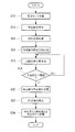
- FIG. 3 is a schematic perspective view showing an example of input value generation of feedforward control in a specific operation of a follow-up target of the work robot system of FIG. 1. It is a flowchart explaining the input value generation process of FIG. It is a schematic perspective view which shows an example of the operation of the robot which was feedforward controlled by using the input value generated by the input value generation process of FIG.
- the work robot system 1 according to the embodiment of the present disclosure will be described below with reference to the drawings.
- the work robot system 1 of the present embodiment is predetermined with respect to the transfer device 2 that conveys the article 100 to be worked and the work target portion 101 of the article 100 that is conveyed by the transfer device 2. It is equipped with a robot (following robot) 10 that performs the work of.
- the working robot system 1 includes a control device 20 for controlling the robot 10, a detection device 40 as a detection unit, and a visual sensor 50 attached to the robot 10.
- the detection device 40 detects that the article 100 has been transported to a predetermined position.
- the detection device 40 any device having such a function can be used.
- the detection device 40 is a photoelectric sensor, but the visual sensor 50 may detect that the article 100 has been conveyed to a predetermined position.
- Article 100 is not limited to a specific type of item.
- the article 100 is a car body.
- the transport device 2 transports the article 100 by driving several of the plurality of rollers 3 by the motor 2a.
- the transport device 2 transports the article 100 toward the right side in FIG.
- the work target portion 101 is a portion of the article 100 in which the robot 10 performs a predetermined work.
- the hand (tool) 30 of the robot 10 lifts the component 110, and the robot 10 attaches the attachment portion 111 of the component 110 to the work target portion 101.
- the shaft 111a extending downward from the mounting portion 111 of the component 110 fits into the hole 101a provided in the work target portion 101 of the article 100.
- the robot 10 attaches the attachment portion 111 of the component 110 to the work target portion 101 while the article 100 is being moved by the transfer device 2.
- the robot 10 is not limited to a specific type, but the robot 10 of the present embodiment includes a plurality of servomotors 11 for each of a plurality of movable arms 10a (see FIG. 2).
- Each servomotor 11 has an operating position detecting device for detecting its operating position, and the operating position detecting device is an encoder as an example. The detection value of the operating position detecting device is transmitted to the control device 20.
- a hand 30 is attached to the tip of the arm 10a.
- the hand 30 of the present embodiment supports the component 110 by gripping with a plurality of claws, but it is also possible to use a hand that supports the component 110 by using magnetic force, suction of air, or the like.
- the hand 30 includes a servomotor 31 that drives the claws (see FIG. 2).
- the servomotor 31 has an operating position detecting device for detecting the operating position thereof, and the operating position detecting device is an encoder as an example. The detection value of the operating position detecting device is transmitted to the control device 20.
- various servomotors such as a rotary motor and a linear motion motor can be used.
- a force sensor 32 is attached to the tip of the robot 10.
- the force sensor 32 measures, for example, a force or a moment in the X-axis direction, the Y-axis direction, and the Z-axis direction shown in FIG. 3, and around the X-axis, the Y-axis, and the Z-axis.
- the force sensor 32 may be any as long as it can detect the direction of the force applied to the hand 30 or the component 110 gripped by the hand 30 and the degree of the force. Therefore, in the present embodiment, the force sensor 32 is provided between the robot 10 and the hand 30, but the force sensor 32 may be provided in the hand 30.
- a visual sensor 50 is attached to the tip of the arm 10a.
- the visual sensor 50 is attached to the wrist flange of the robot 10 using a frame 50a.
- the visual sensor 50 is a two-dimensional camera.
- the visual sensor 50 of the present embodiment provides image data as shown in FIG. 3 so that the tracking target 102 whose position and posture do not change relative to the work target portion 101 falls within a predetermined range of the angle of view. Acquire sequentially.
- the follow-up target 102 is the upper surface portion shown by the diagonal line in FIG. 3, but it is also possible to use another portion whose position and posture do not change relative to the work target portion 101.
- the visual sensor 50 may be attached to a tool such as the hand 30. Further, the visual sensor 50 may be attached to another place of the robot 10 whose relative position and posture do not change with the tool such as the hand 30.
- the visual sensor 50 sequentially transmits image data to the control device 20.
- the image data is data that can specify the position and posture of the tracking target 102.
- the image data may be processed by a detector other than the control device 20, and the position and orientation of the tracking target 102 may be specified based on the processed data.
- the follow-up target 102 is a portion of the article 100 having a predetermined shape, a portion provided with a predetermined mark, and the like.
- the image data is data that can determine the position and orientation of the above portion on the image.
- the position and posture of the hand 30 attached to the arm 10a is changed.
- the position and posture of the hand 30 attached to the arm 10a and the position and posture of the visual sensor 50 are associated with each other by calibration.
- the control device 20 recognizes the position and posture of the tracking target 102 in the coordinate system of the robot 10 based on the image data, and the control device 20 uses the hand 30 provided on the arm 10a at a position required for a predetermined work. It can be moved to the posture.
- the shaft 111a of the mounting portion 111 of the component 110 can be fitted into the hole 101a provided in the work target portion 101 of the article 100.
- the article 100 may swing on the transport device 2. For example, if the plurality of rollers 3 of the transport device 2 are not arranged on a perfect plane, the article 100 swings. When the article 100 is large, a slight shaking on the lower end side of the article 100 may lead to a large shaking of the work target portion 101. Therefore, it is important to adjust the posture of the hand 30 provided on the arm 10a.
- changes in the position, posture, and size of the tracking target 102 on the image data of the visual sensor 50 and changes in the position and posture of the coordinate system of the robot 10 are determined in advance in the control device 20. It is related.
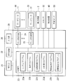
- the control device 20 includes a control unit 21 having a CPU, RAM, and the like, a display device 22, and a storage unit (feature amount storage unit, input value storage unit) having a non-volatile storage, ROM, and the like. It is equipped with 23. Further, the control device 20 is connected to a plurality of servo controllers 24 corresponding to the servomotors 11 of the robot 10, a servo controller 25 corresponding to the servomotor 31 of the hand 30, and a control device 20. It also has an input unit 26. In one example, the input unit 26 is an input device such as an operation panel that can be carried by the operator. The input unit 26 may perform wireless communication with the control device 20.
- the system program 23a is stored in the storage unit 23, and the system program 23a has a basic function of the control device 20. Further, the operation program 23b is stored in the storage unit 23. Further, the storage unit 23 includes a follow-up control program (movement command means) 23c, a force control program 23d, a feature amount detection program (feature amount detection means) 23e, and a movement amount calculation program (movement amount calculation means) 23f. Is stored.
- the signal acquired when the specific operation of the follow-up target 102 starts and the input value of the feedforward control are stored in association with each other.
- the specific operation of the follow-up target 102 is an unsteady operation assumed during the operation of the transport device 2 for transporting the article 100, and is a stop, a restart from the stop, or an emergency stop due to another work process. Etc.
- a signal capable of specifying each specific operation is acquired by the control device 20.
- control unit 21 transmits a movement command for performing a predetermined work on the article 100 to the servo controllers 24 and 25.
- the robot 10 and the hand 30 perform a predetermined operation on the article 100.
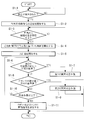
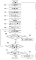
- the operation of the control unit 21 at this time will be described with reference to the flowchart of FIG.
- step S1-1 when the article 100 is detected by the detection device 40 (step S1-1), the control unit 21 starts transmitting a pre-work movement command to the robot 10 and the hand 30 based on the operation program 23b (step S1). -2). As a result, the robot 10 brings the shaft 111a of the component 110 gripped by the hand 30 closer to the hole 101a of the work target portion 101. At this time, the control unit 21 may use data such as the transfer speed of the transfer device 2, the position data of the work target unit 101 in the article 100, and the like. Further, after step S1-4 described later, the shaft 111a of the component 110 is fitted into the hole 101a of the article 100 based on the operation program 23b. In step S1-1, the article 100 may be detected by the visual sensor 50 instead of the detection device 40.
- step S1-2 Under the control of the robot 10 in step S1-2, the component 110 reaches a predetermined work (fitting) preparation position and posture.
- the control unit 21 controls the tracking control program 23c.
- Control based on the feature amount detection program 23e and the movement amount calculation program 23f is started (step S1-4).
- step S1-4 for example, the following control is performed.
- at least the position and posture of the tracking target 102 are detected based on the image data of the visual sensor 50, and the control unit 21 is attached to the arm 10a based on the detected position and posture of the visual sensor 50.
- the position and posture are made to follow the tracking target 102.
- the hand 30 of the robot 10 is an article in such a manner that the tracking target 102 is always arranged at the target position and posture of the image data of the visual sensor 50.
- follow 100 Such control is realized by, for example, the following control.
- the storage unit 23 stores the target position, the target posture, and the target size to which the follow-up target 102 should be arranged in the image data as the first feature amount.
- the target size is, for example, the size of the contour when the feature is the contour.
- the control unit 21 Based on the feature amount detection program 23e, the control unit 21 detects the position, posture, and size of the tracking target 102 on the image data sequentially obtained by the visual sensor 50 as the detection of the second feature amount.
- the control unit 21 projects and transforms the model of the tracking target 102 stored in the storage unit 23, and performs a matching search between the projected model and the tracking target 102 on the image data to perform a tracking target.
- the position and orientation of 102 are detected.
- the model may be created using CAD data or the like, or may be created from an actual object. Since the relative position and the relative posture of the work target unit 101 and the follow-up target 102 are fixed, the control unit 21 has the relative position and the relative position of the tip portion of the arm 10a and the follow-up target 102 based on the position and the posture of the follow-up target 102. You can get a relative posture.
- the control unit 21 calculates a movement command for matching the position, posture, and size of the tracking target 102 in the image data with the first feature amount based on the movement amount calculation program 23f.
- the calculated movement command is for eliminating or reducing the difference between the position, posture, and size of the tracking target 102 in the image data and the first feature amount.
- the calculated movement command changes, for example, the position of the hand 30 attached to the arm 10a in the X-axis direction, the Y-axis direction, and the Z-axis direction, and changes the posture of the hand 30 around the X-axis, around the Y-axis, and around the Y-axis. It is changed around the Z axis.
- the control unit 21 may further adjust the calculated movement command based on the parameters determined by the mechanical characteristics of the arm 10a.
- the mechanical properties include the rigidity of the entire or part of the arm 10a, the rigidity of each movable part, the weight of the hand 30, the weight of the component 110, the moment received by the arm 10a due to the weight of the hand 30 and the component 110, and the like. Is done. Further, since the amount of bending, the direction, and the like of the arm 10a change according to the angle of the joint which is the movable portion of the arm 10a, the state of each movable portion of the arm 10a is also included in the mechanical properties.
- the posture of the arm 10a changes due to the movement command
- the moment received by the arm 10a, the state of each movable part of the arm 10a, etc. change depending on the weight of the hand 30 and the component 110, etc., according to the posture change. Therefore, if the movement command is adjusted in consideration of these mechanical characteristics, the hand 30 can be made to follow the article 100 more accurately.
- the control unit 21 can obtain the tendency of the change of the second feature amount by using a plurality of continuous image data. For example, when the position, posture, and size of the follow-up target 102 on the image data of the visual sensor 50 are gradually approaching the first feature amount which is the target data, a plurality of continuous image data are used with respect to the follow-up target 102. The tendency of changes in the relative position and relative posture of the visual sensor 50 can be captured.
- control unit 21 may adjust the movement command based on the movement amount calculation program 23f using feedforward control based on the tendency.
- the average speed may be obtained from the change in the amount of movement, and the basic speed may be given as feedforward control.
- feedforward control it is possible to feedback control the deviation while keeping the relative speed with the target constant to some extent. If feedforward is not used, there may be a moment when the moving speed of the robot becomes 0 when the features of the images match. In this case, deceleration and acceleration may occur frequently, but such deceleration and acceleration can be prevented by using feedforward control.
- the correction data to which feedforward is applied is subjected to well-known filtering processing such as moving average, smoothing processing, and the like.
- filtering processing such as moving average, smoothing processing, and the like.
- the input value such as the basic speed given to the feedforward control may be arbitrarily input by the user based on the one measured by an external measuring instrument. Further, the vibration of the arm may be reduced by creating a robot model in consideration of the deflection (twist) of the speed reducer and estimating and feeding back the vibration of the arm.
- feedforward control is performed on the assumption that the follow-up target 102 performs a specific operation as a case where the relative position and the relative posture tend to change. That is, when the signal when the follow-up target 102 starts the specific operation is acquired, the input value stored in the storage unit 23 is read out in association with the signal, and the feedforward control is performed based on the input value. I do.
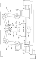
- the input value of the feedforward control is acquired in advance by the following method. First, as shown in FIG. 5, a visual sensor 50 fixed to the floor surface to which the transport device 2 is fixed is prepared.
- the tracking target 102 is arranged within the angle of view of the visual sensor 50, and the visual sensor 50 is operated (step S10). Then, the above-mentioned specific operation is executed (step S11). For example, when the emergency stop of the transport device 2 is executed, an emergency stop signal (specific signal) capable of specifying the emergency stop is acquired by the control device 20 (step S12).
- an emergency stop signal specific signal capable of specifying the emergency stop is acquired by the control device 20 (step S12).
- the follow-up target 102 vibrates in the trajectory shown in FIG.
- the image data including the follow-up target 102 is sequentially acquired by the visual sensor 50 at minute time intervals, and the position of the follow-up target 102 is sequentially detected by processing the acquired image data ( Step S13).
- step S14 the change in the position of the detected follow-up target 102 is determined (step S14), and when the change in the position exceeds a predetermined threshold value, the process from step S13 is repeated.
- step S14 the change in position becomes equal to or less than a predetermined threshold value in step S14, the locus of the tracking target 102 in the robot coordinate system is calculated from the information on the position of the tracking target 102 acquired in time series (step S15). ).
- the input value of the feedforward control is calculated based on the locus of the follow-up target 102 (step S16). Specifically, as shown in FIG. 7, the input value of the feedforward control is calculated as a command signal that matches the locus of the robot 10 with the locus of the follow-up target 102.
- the calculated input value is a command signal that changes over a finite time interval, and is stored in association with a signal that can specify the acquired specific operation (step S17).
- the input value of the feedforward control is calculated in the same manner for the specific operation other than the emergency stop, and is stored in the storage unit 23 in association with the signal capable of specifying each specific operation.
- step S20 a specific operation of the follow-up target 102 is generated.
- the control device 20 acquires a specific signal capable of specifying the specific operation (step S21).
- the control device 20 reads out the input value stored in the storage unit 23 in association with the acquired specific signal (step S22), and feedforward control is performed in which the input value is added to the sequential command signal at predetermined minute time intervals. Start (step S23). At this time, an image including the follow-up target 102 is acquired by the visual sensor 50 provided in the robot 10 (step S24), and the acquired image is processed to detect the position of the follow-up target 102 on the image (step S25). ..
- step S26 it is sequentially determined whether or not the detected position of the follow-up target 102 is within a predetermined range (step S26), and if the position is deviated beyond the predetermined range, the position of the follow-up target 102 is determined.
- the direction of deviation and the amount of displacement are stored in association with the time of the input value (step S27).
- step S28 it is determined whether or not the input value is completed (step S28), and from step S25 until the input value is completed. The process is repeated.
- the feedforward control input value stored in the storage unit 23 is corrected based on the position shift of the stored tracking target 102 (step S29).
- the input value may be finely adjusted by repeating the steps from step S20 to step S29 until the positional deviation of the tracking target 102 becomes equal to or less than a predetermined range with respect to the input value over the entire period.
- the tool 30 of the robot 10 can be accurately followed by the article 100 even if a non-steady operation of the transfer device 2 occurs during actual work using the robot 10 according to the present embodiment.
- the visual sensor 50 provided in the robot 10 is used when setting the input value of the feedforward control, there is an advantage that the setting can be easily performed.
- the visual sensor 50 may be prepared separately from the visual sensor 50 attached to the robot 10. In this case, the visual sensor 50 fixedly installed on the floor surface is calibrated with respect to the coordinate system of the robot 10. When the visual sensor 50 attached to the robot 10 is used, the robot 10 is kept stationary. In this case, the visual sensor 50 is calibrated with respect to the coordinate system of the robot 10.
- control unit 21 may interpolate the detection result of the second feature amount by using the tendency of changes in the relative position and the relative posture. Therefore, even if the acquisition cycle of the second feature amount is as long as the imaging cycle of the visual sensor 50, the second feature amount can be estimated during the acquisition cycle by interpolating the detection result, and in the future. It is possible to estimate the second feature amount.
- control unit 21 causes the hand 30 of the arm 10a to follow the work target unit 101.
- the position and posture of the shaft 111a of the mounting portion 111 of the component 110 and the position and posture of the hole 101a of the work target portion 101 coincide with each other.
- the change in the position, posture, and size of the tracking target 102 on the image data of the visual sensor 50 and the change in the position and posture of the coordinate system of the robot 10 are related in the control device 20. It is attached. Therefore, when the visual sensor 50 is following the tracking target 102, the coordinate system of the robot 10 moves in the transport direction of the transport device 2, and the position and posture of the coordinate system match the movement of the article 100 by the transport device 2. be able to. In this situation, the work target unit 101 of the article 100 is moved by the transport device 2, but when viewed from the control unit 21, the work target unit 101 appears to be almost stopped in the coordinate system.
- the control unit 21 starts force control based on the force control program 23d (step S1-5).
- the force control a well-known force control can be used.
- the robot 10 moves the component 110 in a direction to escape from the force detected by the force sensor 32.
- the amount of movement is determined by the control unit 21 according to the detected value of the force sensor 32.
- the force sensor 32 detects a force in the direction opposite to the transport direction by the transport device 2.
- the control unit 21 slightly moves the component 110 in the direction opposite to the transport direction to escape from the detected force.
- the control unit 21 performs the first abnormality response operation when the second feature amount sequentially detected based on the image data of the visual sensor 50 fluctuates beyond a predetermined reference (step S1-6).
- Fluctuations exceeding a predetermined reference include a large movement of the tracking target 102 in the image data, a movement faster than the predetermined speed of the tracking target 102 in the image data, and the like. If the power supply is not stable, the rotation speed of the motor 2a may drop sharply, and the rotation speed of the motor 2a may fluctuate significantly. In these cases, the position of the tracking target 102 with respect to the tip end portion of the arm 10a will fluctuate beyond a predetermined reference.
- the control unit 21 operates to shorten the control cycle of force control or increase the sensitivity, to stop the progress of fitting, to stop the fitting work, and what is the fitting direction.
- the operation of retracting in the opposite direction, the operation of stopping the transportation, or the operation of combining them is performed.
- the control unit 21 performs an operation of stopping the fitting operation, an operation of retracting in the direction opposite to the fitting direction, an operation of stopping the transport device 2, or an operation in which they are combined.
- step S1-8 when the second feature amount is equal to or less than a predetermined reference value in step S1-6 and the detected value of the force sensor 32 exceeds the predetermined reference value (step S1-8), the control unit 21 has a second abnormality. The corresponding operation is performed (step S1-9).
- the control unit 21 performs the following operation as the second abnormality response operation.
- an operation of stopping the robot 10 an operation of moving the robot 10 in a direction of escaping from the direction of the force detected by the force sensor 32, an operation of stopping the transport device 2, an operation of retracting in the direction opposite to the fitting direction, and an operation of retracting.
- the operation of stopping the transportation or the operation of combining them is performed.
- the control unit 21 operates to stop the robot 10.
- step S1-8 determines whether or not the fitting operation is completed (for example, the traveling distance in the Z direction is a predetermined value).
- Step S1-10 determines whether or not the fitting operation is completed (for example, the traveling distance in the Z direction is a predetermined value).
- Step S1-10 determines whether or not the fitting operation is completed (for example, the traveling distance in the Z direction is a predetermined value).
- a predetermined movement command or operation command is sent to the arm 10a and the hand 30 (step S1-11).
- the hand 30 releases the component 110 and moves away from the component 110, and the hand 30 moves to the standby position or the place where the next component 110 is stocked by the arm 10a. If it is determined in step S1-10 that the fitting operation has not been completed, the steps from step S1-6 are repeated.
- control unit 21 performs a wide range detection process for detecting the second feature amount in the first range in the image data based on the feature amount detection program 23e, and the image data obtained thereafter.
- the narrow range detection process may be performed in the second range.
- the narrow range detection process is a process of detecting a second feature amount in a second range narrower than the first range.
- the difference between the first feature amount and the second feature amount is large, a wide range detection process is performed, and when the difference between the first feature amount and the second feature amount becomes a predetermined value or less, a narrow range detection is performed. Processing is done. As a result, when the difference between the first feature amount and the second feature amount becomes small, it becomes possible to improve the processing speed, the processing accuracy, and the like.
- the control unit 21 sets the area including the tracking target 102 detected in the image data as the detection range of the second feature amount based on the feature amount detection program 23e. May be good.
- the detection range can be set by setting the circumscribed rectangle in contact with the contour of the detected follow-up target 102 and enlarging the circumscribed rectangle by a predetermined magnification.
- the magnification may be changed according to the size (size) of the tracking target 102 in the image data, the distance between the visual sensor 50 and the tracking target 102, and the like. For example, when the visual sensor 50 and the follow-up target 102 come close to each other, the amount of movement of the follow-up target 102 on the image in the image data increases, so that the magnification is increased. As a result, the position and orientation of the tracking target 102 can be detected efficiently and accurately.
- the hand 30 as a tool may be attached to a working robot 60 which is another robot.
- the arm 60a and the hand 30 of the working robot 60 are controlled by the control device 70.
- the control device 70 has the same configuration as the control device 20, and the arm 60a also has the same configuration as the arm 10a.
- the position and direction of the coordinate system of the visual sensor 50 and the position and direction of the coordinate system of the robot 60 are related in the control device 70.
- the control device 70 operates the robot 60 in the coordinate system of the robot 60 while the control unit 21 makes the visual sensor 50 follow the tracking target 102. Since the position and posture of the coordinate system of the robot 60 change according to the position and posture of the coordinate system of the visual sensor 50, the control device 70 performs the work using the operation program 23b set based on the coordinate system of the robot 60. be able to.
- the control device 20 follows the position and posture of the visual sensor 50 to the tracking target 102, the information of the movement command, the difference between the second detection amount and the first detection amount.
- the position and posture of the coordinate system of the robot 60 can be made to follow the work target portion 101 based on the information and the like. Therefore, when the robot 60 performs the work of fitting the shaft 111a of the component 110 into the hole 101a of the article 100 based on the operation program 23b, the hand 30 of the robot 60 follows the article 100.
- the control device 20 and the control device 70 may be connected to a higher-level control system such as a production control system, and information may be exchanged between the control device 20 and the control device 70 via the higher-level control system.
- a higher-level control system such as a production control system
- the robot 60 it is also possible to use a robot having a rail provided above the transport device 2 along the transport device 2 and a movable arm movably attached to the rail.
- the visual sensor 50 is attached to the tip of the movable arm, and the movable arm can change the posture of the tip and the visual sensor 50, for example, around the X-axis and around the Y-axis.
- the movable arm can move the position of the tip and the visual sensor 50 in the Y-axis direction, but even if the movable arm cannot freely move the position of the tip and the visual sensor 50 in the Y-axis direction. good. Even in this case, the position and posture of the visual sensor 50 attached to the movable arm can be made to follow the tracking target 102.
- the position of the visual sensor 50 attached to the movable arm in the X-axis direction is based on the difference between the second feature amount and the first feature amount.
- X-axis and Y-axis postures can be made to follow the follow-up target 102. If the tracking can be performed, even if the tracking target 102 may move in the Y-axis direction in the image data, the movement amount can be detected and the same effect as described above can be obtained.
- the storage unit 23 stores the first feature amount related to the shape and the like of the follow-up target 102. Since the shape of the tracking target 102 changes according to the distance and angle between the arm 10a and the tracking target 102, the tracking control can be performed more accurately.
- a plurality of visual sensors 50 are used, and it is also possible to make the plurality of visual sensors 50 follow each of the plurality of tracking targets 102.
- the follow-up target 102 is arranged at each predetermined position in the plurality of image data obtained by the plurality of visual sensors 50
- the hand 30 attached to the arm 10a refers to the work target portion 101 of the article 100. It is also possible to determine that they are placed in a predetermined position and posture.
- the robot 10 of the present embodiment has the first target data for making the at least one visual sensor 50 provided on the arm 10a and the visual sensor 50 provided on the arm 10a follow the tracking target 102.
- a storage unit 23 for storing a feature amount is provided. Then, in the present embodiment, the second feature amount relating to the current at least position and posture of the follow-up target 102 is detected by using the image obtained by the visual sensor 50.
- the movement command of the arm 10a is calculated based on the difference between the second feature amount and the first feature amount. Further, while the visual sensor 50 follows the tracking target 102, the calculation of the movement command and the movement of the arm based on the movement command are repeated. Therefore, the relative position and the relative posture of the hand 30 with respect to the article 100 transported by the transport device 2 can be gradually brought closer to the target data. This is useful for accurately following the operation of the arm 10a of the robot 10 with the article 100 being conveyed by the conveying device 2.
- the model of the follow-up target 102 is provided as the first feature amount.
- the control unit 21 performs a matching search between the feature unit in the image data obtained by the visual sensor 50 and the projected model, thereby performing a matching search for the feature in the image data.
- the position and posture of the portion (second feature amount) can be obtained.
- This configuration is useful for accurately approaching the relative position and posture of the visual sensor 50 with respect to the tracking target 102 of the article 100 transported by the transport device 2 to the target data.
- the feature portion may be a figure provided on the surface of the article 100.
- the movement command is adjusted by using at least feedforward control.
- the feedforward control is performed in consideration of the movement tendency of the article 100 by the transport device 2, which quickly uses the relative position and the relative posture of the visual sensor 50 with respect to the tracking target 102 of the article 100 as target data. Useful for getting closer.
- the control unit 21 uses the data obtained by the visual sensor 50 or another sensor 40 to set the tracking target 102 of the visual sensor 50. Calculate the pre-work movement command to put it within the detection range. Therefore, the visual sensor 50 is arranged at a position required for tracking in a short time before the tracking control of the arm 10a is performed.
- the work robot system of the present embodiment includes a transfer device 2 and a robot 10, and the robot 10 is designated as an article 100 in a state where the visual sensor 50 provided in the robot 10 is following the tracking target 102. Do the work of.
- the working robot 60 is an article while using the information of the movement command for making the visual sensor 50 provided in the robot 10 follow the tracking target 102 or the information used for calculating the movement command. Perform the predetermined work on 100.
- the work robot 60 When the work robot 60 is used, it is possible to perform a predetermined work on the article 100 at a place away from the visual sensor 50.
- a plurality of working robots 60 may perform a predetermined work on the article 100 by using the above-mentioned information.
- the work robot system of the present embodiment further includes a force sensor 32.
- the force sensor 32 is a force generated by the contact of the component 110 or the hand 30 supported by the robot 10 with the article 100, or the contact of the component 110 or the hand 30 supported by the working robot 60 with the article 100. Detects the force generated by.
- the hand 30 provided on the robot 10 or the work robot 60 is used as the article 100 while using the detection value of the force sensor 32.
- the accuracy of the follow-up control can be further improved.
- the follow-up target 102 is a part of the article 100.
- the position of the tracking target 102 in the article 100 is fixed, which is useful for further improving the accuracy of the tracking control.
- the processing tool may be supported on the tip of the robot 10 or the work robot 60, and the robot 10 or the work robot 60 may process the article 100 conveyed by the transfer device 2 as a predetermined work.
- the machining tool is a drill, a milling cutter, a drill tap, a deburring tool, other tools, and the like.
- the processing tool may be a welding gun, a welding torch, or the like.
- the transport device 2 it is possible to use a transport device that transports the article 100 along a curved route, and it is also possible to use a transport device that transports the article 100 along a winding route. Even in these cases, the control unit 21 can make the tip portion of the robot 10 or the work robot 60 follow the work target unit 101 by using the detection result of the visual sensor 50.
- control unit 21 can perform the first abnormality response operation in step S1-7. Therefore, even when the transport device is used, the same effect as described above is achieved.
- another robot may move the article 100. Even in this case, the same effects as described above can be achieved. Further, when the article 100 is an automobile, a frame of an automobile, or the like, the article 100 on which a predetermined work is performed may be moved by its engine, wheels, or the like. In these cases, other robots, engines, wheels, etc. function as transport devices.
- AGV Automated Guided Vehicle
- the article 100 may be transported by a shooter in which the article 100 slides down, rolls down, or falls due to gravity. In this case, it is also possible to vibrate the tilted shooter with a vibration exciter, thereby smoothing the movement of the article 100 on the shooter. In these cases, the shooter, the vibration device, and the like function as a transport device, and the article 100 moved by the shooter is taken out by a tool attached to the robot 10.
- the force sensor 32 is attached to the tip of the robot 10 or the working robot 60.
- the force sensor 32 it is also possible to arrange the force sensor 32 between the transport device 2 and the article 100, inside the article 100, or the like. Even in this case, it is possible to perform force control based on the detected value of the force sensor 32, and the same effect as described above is achieved.
- the visual sensor 50 may be attached to a portion other than the wrist flange of the robot 10 or the working robot 60.
- the visual sensor 50 may be a stereo camera. In this case, it is possible to obtain the distance image data of the follow-up target 102 by a pair of cameras, and the position and the posture of the follow-up target 102 are specified by using the image data and the corresponding three-dimensional model.
- the target followed by the visual sensor 50 and the work target of the robot 10 are different, but the target followed by the visual sensor 50 and the work target of the robot 10 may be the same.
- the target followed by the visual sensor 50 and the work target of the robot 10 may be the same.
- the target to be worked on and the target to be worked on can be the same.
- the position, posture, and size of the tracking target 102 are arranged at the target position on the image data of the visual sensor 50, whereby the position and posture of the hand 30 as a tool are determined with respect to the article 100. Place in the position and posture required for the work.
- the position and posture of the tracking target 102 are placed at the target position on the image data of the visual sensor 50, whereby the position and posture of the tool attached to the robot 10 are set to the positions and postures required for the predetermined work. It may be arranged.
- the first method is used.
- the size information as a feature quantity and the size information as a second feature quantity may not be used.
- the one that calculates the locus of the follow-up target 102 in the robot coordinate system is exemplified, but the specific operation of the follow-up target 102 in the robot coordinate system (for example, the stop operation or the restart from the stopped state) is illustrated. Only the elapsed time of the operation) may be calculated and used as the time constant of the specific operation.
- Step S31 When the change in position becomes equal to or less than a predetermined threshold value in step S14, the time when the tracking target 102 is stopped is stored in the storage unit 23 as the specific operation stop time (step S32).
- the elapsed time is calculated as the difference between the stored specific operation start time and the specific operation stop time (step S33), and the calculated elapsed time is used as a time constant to specify each specific operation of the follow target 102. It is stored in the storage unit 23 in association with the above (step S34).
- the specific operation ends (for example, when the speed becomes constant after the operation is completely stopped or the operation is restarted from the stopped state).
- the operator visually determines the stop of the follow target 102 without using the visual sensor 50, and uses a measuring device such as a stop watch. The elapsed time may be measured. If the time constant can be specified from the setting of the inverter of the transport device 2, the time constant specified from the setting may be used as it is.
- step S40 a specific operation of the follow-up target 102 is generated.
- the control device 20 stores the time when the specific signal is acquired in the storage unit 23 as the specific operation start time after the specific signal that can specify the specific operation is acquired (step S41) (step S41).
- step S42 the time constant set by the control device 20 is read from the storage unit 23 (step S43), and feed forward control is started according to the set time constant (step S44).
- step S45 the initial value of the maximum misalignment amount of the follow-up target 102 is set to 0 (step S45).
- step S46 an image including the follow-up target 102 is acquired by the visual sensor 50 provided in the arm 10a of the robot 10 (step S46), and the acquired image is processed to detect the position of the follow-up target 102 on the image (step). S47).
- step S48 it is determined whether or not the absolute value of the detected misalignment of the tracking target 102 is larger than the absolute value of the stored maximum misalignment (step S48), and the misalignment of the tracking target 102 is determined.
- the absolute value of is larger than the absolute value of the maximum misalignment amount
- the maximum misalignment amount is updated and stored in the storage unit 23 (step S49).
- step S50 the process from step S47 is repeated.
- the tracking target 102 and the robot 10 are stopped, so that the amount of change in the positional deviation becomes 0. Further, when the specific operation is restarted from the stop, the tracking target 102 and the robot 10 become constant speeds, and if the speeds are the same, the amount of change in the position shift becomes 0, and if there is a speed difference, the position shift occurs.
- the amount of change over time is a non-zero constant value.
- Step S51 After a lapse of time from the set time constant and the time change amount of the change amount of the position shift becomes a constant value, it is determined whether or not the absolute value of the maximum position shift amount becomes larger than the predetermined threshold value. (Step S51).
- the absolute value of the maximum misalignment amount is equal to or less than a predetermined threshold value, it is determined whether to increase or decrease the time constant according to the sign of the maximum misalignment amount, and the absolute value of the maximum misalignment amount is determined.
- the amount is added to or subtracted from the time constant, and the time constant of the feed forward control stored in the storage unit 23 is updated (step S52).
- the increase / decrease amount ⁇ T according to the absolute value of the maximum misalignment amount may be calculated by, for example, the following equation (1).
- ⁇ T D / V (1)
- D is the maximum amount of misalignment
- V is the constant speed of the tracking target 102.
- step S51 the process is repeated from step S40 until the absolute value of the maximum misalignment amount becomes equal to or less than the predetermined threshold value, and when the absolute value of the maximum misalignment amount becomes equal to or less than the predetermined threshold value, the process ends.
- the follow-up target 102 accelerates or decelerates immediately from the time when a specific signal capable of specifying a specific operation is acquired to execute the specific operation, but instead of this, the time when the specific signal is acquired.
- the follow-up target 102 may be accelerated or decelerated corresponding to a specific signal at predetermined time intervals. In this case, an arbitrary time is set as the predetermined time interval.
- the input value of the feedforward control acquired by the above method is the same as the transport device 2 for transporting the article 100 (the same transport device as an object, or the same specifications and settings. It may be used for another robot that works on the transport device).
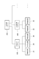
- a plurality of control devices 20 may be connected to the host control system 100.
- the host control system 100 is, for example, a computer connected to a plurality of control devices 20 by wire, a computer arranged on the same site as the plurality of control devices 20, and the like.
- the host control system 100 is sometimes referred to as a fog computer.
- the upper control system 100 may be a production management system, a shipping management system, a robot management system, a department management system, or the like.
- a plurality of higher control systems 100 may be connected to another higher control system 200 or the like.
- the other higher control system 200 is, for example, a cloud server connected to a plurality of higher control systems 100 by wire or wirelessly.
- a management system is formed by a plurality of control devices 20 and an upper control system 100.
- the host control system 100 includes a control unit having a processor and the like, a display device, a storage unit having a non-volatile storage, a ROM, a RAM, and the like, and an input device such as a keyboard, a touch panel, and an operation panel, respectively. ..
- Such a system may include, for example, a plurality of edge computers 8, a plurality of superior control systems 100, and a single or plurality of other superior control systems 200, as shown in FIG.
- the control device 20 and the robot 10 can be edge computers.
- a part of the control device 20 and the robot 10 may be an upper control system.
- Such systems include wired or wireless networks.
- Robot following robot
- 10a arm 23 storage unit (feature quantity storage unit, input value storage unit)
- 23c Follow-up control program (movement command means)
- 23e Feature detection program (feature detection means)
- 23f Movement amount calculation program (movement amount calculation means) 50
- Visual sensor 102
Abstract
アーム(10a)と、アームに設けられた1以上の視覚センサ(50)と、視覚センサを追随対象(102)に追随させるための目標データとして追随対象の少なくとも位置および姿勢に関する第1の特徴量を記憶している特徴量記憶部と、視覚センサによって得られる画像を用いて追随対象の現在の少なくとも位置および姿勢に関する第2の特徴量を検出する特徴量検出手段と、第2の特徴量と第1の特徴量との差異に基づきアームの移動指令を算出し、少なくともフィードフォワード制御を用いて移動指令を調整する移動量計算手段と、移動指令に基づいてアームを移動させる移動指令手段と、追随対象の特定動作の開始時に取得される信号と、特定動作における追随対象の軌跡にアームを追随させるためのフィードフォワード制御の入力値とを対応付けて記憶する入力値記憶部とを備える追随ロボット(10)である。
Description
本開示は、追随ロボットに関するものである。
従来、ロボットと、物品を搬送する搬送装置と、搬送装置に沿って設けられたレールと、レールに沿ってロボットを移動させる移動装置とを備えた生産ラインが知られている(例えば、特許文献1参照。)。
この生産ラインでは、搬送装置によって物品が搬送されている時に、ロボットが物品の欠陥検査および研磨を行う。また、欠陥検査および研磨が行われる時に、搬送装置による物品の搬送速度と同じ速度で、移動装置がロボットをレールに沿って移動させる。
この生産ラインでは、搬送装置によって物品が搬送されている時に、ロボットが物品の欠陥検査および研磨を行う。また、欠陥検査および研磨が行われる時に、搬送装置による物品の搬送速度と同じ速度で、移動装置がロボットをレールに沿って移動させる。
また、ロボットの先端部の位置および姿勢を動かない目標位置に正確に合わせる技術が知られている(例えば、特許文献2参照。)。
前記生産ラインでは、欠陥検査および研磨を行っているだけである。これに対し、例えば、ロボットと物品とが干渉し得る作業が行われる場合には、ロボット、搬送装置、物品等の破損防止の対策が必要になる。しかし、搬送装置によって移動している物品は振動等の予測できない挙動を行う可能性があるので、前記の破損防止を実現することは難しい。
したがって、ロボットのツールを物品に正確に追随させることができることが望まれている。
したがって、ロボットのツールを物品に正確に追随させることができることが望まれている。
本開示の一態様は、可動のアームと、前記アームに設けられた少なくとも1つの視覚センサと、前記アームに設けられた前記視覚センサを追随対象に追随させるための目標データとして前記追随対象の少なくとも位置および姿勢に関する第1の特徴量を記憶している特徴量記憶部と、前記視覚センサによって得られる画像を用いて前記追随対象の現在の少なくとも位置および姿勢に関する第2の特徴量を検出する特徴量検出手段と、前記第2の特徴量と前記第1の特徴量との差異に基づき前記アームの移動指令を算出し、少なくともフィードフォワード制御を用いて前記移動指令を調整する移動量計算手段と、前記移動指令に基づいて前記アームを移動させる移動指令手段と、前記追随対象の特定動作の開始時に取得される信号と、該特定動作における前記追随対象の軌跡に前記アームを追随させるための前記フィードフォワード制御の入力値とを対応付けて記憶する入力値記憶部と、を備え、前記移動量計算手段および前記移動指令手段が、前記視覚センサを前記追随対象に追随させる間、前記移動指令の算出および前記移動指令に基づく前記アームの移動を繰り返し、前記移動指令が、前記第2の特徴量としての前記追随対象の少なくとも位置および姿勢と前記第1の特徴量としての前記追随対象の少なくとも位置および姿勢との差異を減ずるまたは無くすものであり、前記移動量計算手段が、前記特定動作が開始されたときに取得された前記信号に対応付けて前記入力値記憶部に記憶されている前記入力値に基づいた前記フィードフォワード制御を用いる、追随ロボットである。
本開示の一実施形態に係る作業ロボットシステム1について、図面を用いながら以下説明する。
本実施形態の作業ロボットシステム1は、図1に示されるように、作業対象である物品100を搬送する搬送装置2と、搬送装置2によって搬送される物品100の作業対象部101に対して所定の作業を行うロボット(追随ロボット)10とを備えている。また、作業ロボットシステム1は、ロボット10を制御する制御装置20と、検出部としての検出装置40と、ロボット10に取り付けられた視覚センサ50とを備えている。
本実施形態の作業ロボットシステム1は、図1に示されるように、作業対象である物品100を搬送する搬送装置2と、搬送装置2によって搬送される物品100の作業対象部101に対して所定の作業を行うロボット(追随ロボット)10とを備えている。また、作業ロボットシステム1は、ロボット10を制御する制御装置20と、検出部としての検出装置40と、ロボット10に取り付けられた視覚センサ50とを備えている。
検出装置40は、物品100が所定位置まで搬送されてきたことを検出する。検出装置40として、このような機能を有する装置は全て利用することができる。本実施形態では検出装置40は光電センサであるが、視覚センサ50によって物品100が所定位置まで搬送されてきたことを検出してもよい。
物品100は特定の種類の物に限定されない。本実施形態では、一例として、物品100は車のボディである。搬送装置2はモータ2aによって複数のローラ3のうち数本を駆動することによって物品100を搬送するものである。本実施形態では搬送装置2は図1における右側に向かって物品100を搬送する。
作業対象部101は、物品100において、ロボット10が所定の作業を行う部分である。本実施形態では、所定の作業として、ロボット10のハンド(ツール)30が部品110を持上げ、ロボット10は部品110の取付部111を作業対象部101に取り付ける。これにより、例えば、部品110の取付部111から下方に延びるシャフト111aが、物品100の作業対象部101に設けられた孔101aに嵌合する。
ロボット10は、物品100が搬送装置2によって移動している状態において、部品110の取付部111を作業対象部101に取り付ける。
ロボット10は、物品100が搬送装置2によって移動している状態において、部品110の取付部111を作業対象部101に取り付ける。
ロボット10は特定の種類に限定されないが、本実施形態のロボット10は、複数の可動のアーム10aをそれぞれ駆動する複数のサーボモータ11を備えている(図2参照)。各サーボモータ11はその作動位置を検出するための作動位置検出装置を有し、作動位置検出装置は一例としてエンコーダである。作動位置検出装置の検出値は制御装置20に送信される。
アーム10aの先端部にはハンド30が取り付けられている。本実施形態のハンド30は複数の爪による把持によって部品110を支持するが、磁力、空気の吸引等を用いて部品110を支持するハンドを用いることも可能である。
ハンド30は爪を駆動するサーボモータ31を備えている(図2参照)。サーボモータ31はその作動位置を検出するための作動位置検出装置を有し、作動位置検出装置は一例としてエンコーダである。作動位置検出装置の検出値は制御装置20に送信される。
各サーボモータ11,31としては、回転モータ、直動モータ等の各種のサーボモータが用いられ得る。
各サーボモータ11,31としては、回転モータ、直動モータ等の各種のサーボモータが用いられ得る。
ロボット10の先端部には力センサ32が取り付けられている。力センサ32は、例えば、図3に示すX軸方向、Y軸方向、およびZ軸方向と、X軸回り、Y軸回り、およびZ軸回りの力またはモーメントを計測する。
力センサ32は、ハンド30またはハンド30によって把持された部品110に加わる力の方向および力の程度を検出できるものであればよい。このため、本実施形態では力センサ32がロボット10とハンド30との間に設けられているが、力センサ32はハンド30内に設けられていてもよい。
アーム10aの先端部には視覚センサ50が取り付けられている。一例では、視覚センサ50は、ロボット10の手首フランジにフレーム50aを用いて取り付けられている。本実施形態では視覚センサ50は2次元カメラである。本実施形態の視覚センサ50は、作業対象部101に対して相対的に位置および姿勢が変化しない追随対象102が画角の所定の範囲に入るように、図3に示されるような画像データを逐次取得する。
本実施形態では追随対象102は図3に斜線で示された上面部であるが、作業対象部101と相対的に位置および姿勢が変化しない他の部分を用いることも可能である。
視覚センサ50は、ハンド30等のツールに取り付けられてもよい。また、視覚センサ50は、ハンド30等のツールと相対位置および姿勢が変化しないロボット10の他の場所に取り付けられてもよい。
視覚センサ50は、ハンド30等のツールに取り付けられてもよい。また、視覚センサ50は、ハンド30等のツールと相対位置および姿勢が変化しないロボット10の他の場所に取り付けられてもよい。
視覚センサ50は画像データを制御装置20に逐次送信する。画像データは追随対象102の位置および姿勢を特定できるデータである。画像データが制御装置20以外の検出器によって処理され、当該処理後データに基づき追随対象102の位置および姿勢が特定されてもよい。
追随対象102は、物品100において所定の形状を有する部分、所定のマークが設けられた部分等である。これらの場合、画像データは、画像上で上記部分の位置および姿勢を判別できるデータである。
画像をベースとする例では、視覚センサ50に対して追随対象102が画像データ(検出範囲)の目標位置や姿勢、サイズに配置されると、アーム10aに取り付けられたハンド30の位置および姿勢が物品100に対する所定の作業に必要な位置および姿勢となる。位置をベースとする例では、アーム10aに取り付けられたハンド30の位置および姿勢と視覚センサ50の位置および姿勢とがキャリブレーションによって対応付けられている。この場合は、画像データに基づき制御装置20がロボット10の座標系における追随対象102の位置および姿勢を認識し、制御装置20がアーム10aに設けられたハンド30を所定の作業に必要な位置および姿勢に移動させることができる。
本実施形態では、部品110の取付部111のシャフト111aを物品100の作業対象部101に設けられた孔101aに嵌合できる状態となる。
物品100は搬送装置2上で揺動する場合がある。例えば、搬送装置2の複数のローラ3が完全な平面上に配置されていない場合、物品100は揺動する。物品100が大きい場合、物品100の下端側の僅かな揺れが作業対象部101の大きな揺れに繋がる場合もある。このため、アーム10aに設けられたハンド30の姿勢調整は重要である。
物品100は搬送装置2上で揺動する場合がある。例えば、搬送装置2の複数のローラ3が完全な平面上に配置されていない場合、物品100は揺動する。物品100が大きい場合、物品100の下端側の僅かな揺れが作業対象部101の大きな揺れに繋がる場合もある。このため、アーム10aに設けられたハンド30の姿勢調整は重要である。
画像をベースとする例では、視覚センサ50の画像データ上での追随対象102の位置や姿勢、サイズの変化と、ロボット10の座標系の位置および姿勢の変化とは、制御装置20内において予め関係付けられている。
制御装置20は、図2に示されるように、CPU、RAM等を有する制御部21と、表示装置22と、不揮発性ストレージ、ROM等を有する記憶部(特徴量記憶部、入力値記憶部)23とを備えている。また、制御装置20は、ロボット10のサーボモータ11にそれぞれ対応している複数のサーボ制御器24と、ハンド30のサーボモータ31に対応しているサーボ制御器25と、制御装置20に接続された入力部26とを備えている。一例では、入力部26はオペレータが持ち運べる操作盤等の入力装置である。入力部26が制御装置20と無線通信を行う場合もある。
記憶部23にはシステムプログラム23aが格納されており、システムプログラム23aは制御装置20の基本機能を担っている。また、記憶部23には動作プログラム23bが格納されている。また、記憶部23には、追随制御プログラム(移動指令手段)23cと、力制御プログラム23dと、特徴量検出プログラム(特徴量検出手段)23eと、移動量計算プログラム(移動量計算手段)23fとが格納されている。
また、記憶部(入力値記憶部)23には、追随対象102の特定動作が開始するときに取得される信号と、フィードフォワード制御の入力値とが対応付けて記憶されている。
ここで、追随対象102の特定動作とは、物品100を搬送する搬送装置2の稼働中に想定される非定常動作であって、他の作業工程に起因する停止、停止からの再開あるいは非常停止等を意味する。これらの特定動作が開始されるときには各特定動作を特定し得る信号が制御装置20において取得される。
ここで、追随対象102の特定動作とは、物品100を搬送する搬送装置2の稼働中に想定される非定常動作であって、他の作業工程に起因する停止、停止からの再開あるいは非常停止等を意味する。これらの特定動作が開始されるときには各特定動作を特定し得る信号が制御装置20において取得される。
制御部21は、これらのプログラムに基づいて、物品100に対する所定の作業を行うための移動指令を各サーボ制御器24,25に送信する。これによって、ロボット10およびハンド30が物品100に対して所定の作業を行う。この際の制御部21の動作を図4のフローチャートを参照しながら説明する。
先ず、検出装置40によって物品100が検出されると(ステップS1-1)、制御部21は、動作プログラム23bに基づいたロボット10およびハンド30への作業前移動指令の送信を開始する(ステップS1-2)。これにより、ロボット10は、ハンド30によって把持された部品110のシャフト111aを作業対象部101の孔101aに近付ける。このとき、制御部21は、搬送装置2の搬送速度、物品100内における作業対象部101の位置のデータ等を用いてもよい。また、後述のステップS1-4の後で、動作プログラム23bに基づいて、部品110のシャフト111aが物品100の孔101aに嵌合される。なお、ステップS1-1において、検出装置40の代わりに視覚センサ50によって物品100が検出されてもよい。
ステップS1-2のロボット10の制御により、部品110が所定の作業(嵌合)の準備位置および姿勢に到達する。これにより、視覚センサ50の画角(検出範囲)内、または、画角の所定範囲内に追随対象102が存在するようになると(ステップS1-3)、制御部21は、追随制御プログラム23c、特徴量検出プログラム23e、および移動量計算プログラム23fに基づいた制御を開始する(ステップS1-4)。ステップS1-4では、例えば以下の制御が行われる。なお、以下の制御では、視覚センサ50の画像データに基づき追随対象102の少なくとも位置および姿勢が検出され、検出された位置および姿勢に基づいて制御部21がアーム10aに取り付けられた視覚センサ50の位置および姿勢を追随対象102に追随させる。ここで、視覚センサ50はハンド30に対する位置および姿勢が固定されているので、視覚センサ50の画像データの目標位置および姿勢に追随対象102が常に配置される態様で、ロボット10のハンド30が物品100に追随する。
このような制御は、例えば以下の制御によって実現される。
このような制御は、例えば以下の制御によって実現される。
当該制御では、記憶部23には、画像データ内において追随対象102が配置されるべき目標位置および目標姿勢、目標サイズが、第1の特徴量として格納されている。目標サイズは例えば、特徴を輪郭とした場合の輪郭の大きさである。
制御部21は、特徴量検出プログラム23eに基づき、第2の特徴量の検出として、視覚センサ50によって逐次得られる画像データ上で追随対象102の位置、姿勢、およびサイズを検出する。
制御部21は、特徴量検出プログラム23eに基づき、第2の特徴量の検出として、視覚センサ50によって逐次得られる画像データ上で追随対象102の位置、姿勢、およびサイズを検出する。
例えば、制御部21は、記憶部23に格納されている追随対象102のモデルを射影変換しながら、射影変換されたモデルと画像データ上の追随対象102とのマッチング検索を行うことにより、追随対象102の位置および姿勢を検出する。当該モデルはCADデータ等を用いて作成されてもよいし、実際の対象から作成されてもよい。作業対象部101と追随対象102との相対位置および相対姿勢は固定されているので、追随対象102の位置および姿勢に基づき、制御部21はアーム10aの先端部と追随対象102との相対位置および相対姿勢を得ることができる。
制御部21は、移動量計算プログラム23fに基づき、画像データ内における追随対象102の位置、姿勢、およびサイズを第1の特徴量に一致させるための移動指令を算出する。
算出された移動指令は、画像データ内における追随対象102の位置、姿勢、およびサイズと第1の特徴量との差異を無くすまたは低減するためのものである。算出された移動指令は、例えば、アーム10aに取り付けられたハンド30の位置をX軸方向、Y軸方向、およびZ軸方向に変化させ、ハンド30の姿勢をX軸回り、Y軸回り、およびZ軸回りに変化させるものである。
算出された移動指令は、画像データ内における追随対象102の位置、姿勢、およびサイズと第1の特徴量との差異を無くすまたは低減するためのものである。算出された移動指令は、例えば、アーム10aに取り付けられたハンド30の位置をX軸方向、Y軸方向、およびZ軸方向に変化させ、ハンド30の姿勢をX軸回り、Y軸回り、およびZ軸回りに変化させるものである。
なお、上述した制御において、制御部21がさらに、アーム10aの機械的特性により定められるパラメータに基づいて、算出された移動指令を調整してもよい。例えば、アーム10aの全体または一部の剛性、各可動部の剛性、ハンド30の重量、部品110の重量、ハンド30および部品110の重量等によってアーム10aが受けるモーメント等が、機械的性質に含まれる。また、アーム10aの可動部である関節の角度に応じてアーム10aの撓み量、方向等が変化するので、アーム10aの各可動部の状態も機械的性質に含まれる。
つまり、移動指令によってアーム10aの姿勢が変化する場合、当該姿勢変化に応じて、ハンド30および部品110の重量等によってアーム10aが受けるモーメント、アーム10aの各可動部の状態等が変化する。このため、移動指令がこれらの機械的特性を考慮して調整されると、ハンド30を物品100にさらに正確に追随させることができる。
制御部21は、連続する複数の画像データを用いて、第2の特徴量の変化の傾向を得ることができる。例えば、視覚センサ50の画像データ上における追随対象102の位置、姿勢、およびサイズが目標データである第1の特徴量に徐々に近付いている時に、連続する複数の画像データから、追随対象102に対する視覚センサ50の相対位置および相対姿勢の変化の傾向が捉えられる。
相対位置および相対姿勢の変化の傾向がある場合、制御部21が、移動量計算プログラム23fに基づき、その傾向に基づくフィードフォワード制御を用いて移動指令を調整してもよい。例えば、移動量の変化から平均速度を求めて、その基本速度をフィードフォワード制御として与えてもよい。
フィードフォワード制御を用いることにより対象との相対速度をある程度一定に保った状態で、ずれ分をフィードバック制御することが可能となる。もしフィードフォワードを用いないと画像の特徴同士が一致した際にロボットの移動速度が0になってしまう瞬間が発生し得る。この場合、減速、加速が頻発してしまう可能性があるが、フィードフォワード制御を用いることでそのような減速、加速を防ぐことができる。
フィードフォワードをかける補正データには、移動平均等の周知のフィルタリング処理、スムージング処理等が施されていることが好ましい。これにより、外乱による物品100の位置および姿勢の変化、搬送装置2の精度に由来する物品100の揺れ、オーバーシュートの可能性、電気的ノイズ等が捉えられると、制御部21は外乱による変化または搬送装置2の精度に由来する揺れへの適切な対応、オーバーシュートの低減、電気的ノイズの除去等が可能となる。
フィードフォワード制御に与える基本速度等の入力値は、外部の計測器で計測したものをもとにユーザが任意に入力してもよい。
また、減速機のたわみ(ねじれ)を考慮したロボットモデルを作成して、アームの振動を推定してフィードバックすることによりアームの振動を軽減してもよい。
また、減速機のたわみ(ねじれ)を考慮したロボットモデルを作成して、アームの振動を推定してフィードバックすることによりアームの振動を軽減してもよい。
本実施形態においては、相対位置および相対姿勢の変化の傾向がある場合として、追随対象102が特定動作を実施した場合を想定し、フィードフォワード制御を行う。すなわち、追随対象102が特定動作を開始したときの信号が取得された場合には、その信号に対応付けて記憶部23に記憶されている入力値を読み出し、その入力値に基づいてフィードフォワード制御を行う。
フィードフォワード制御の入力値は、以下の方法により予め取得しておく。
まず、図5に示されるように、搬送装置2が固定された床面に対して固定された視覚センサ50を用意する。
まず、図5に示されるように、搬送装置2が固定された床面に対して固定された視覚センサ50を用意する。
この状態で、図6に示されるように、視覚センサ50の画角内に追随対象102を配置して、視覚センサ50を作動させる(ステップS10)。次いで、上述した特定動作を実行する(ステップS11)。例えば、搬送装置2の非常停止が実行されると、非常停止を特定し得る非常停止信号(特定信号)が制御装置20に取得される(ステップS12)。
これにより、追随対象102は、図5に示される軌跡で振動する。この軌跡を記録するために、視覚センサ50により追随対象102を含む画像データが微小時間間隔で逐次取得され、取得された画像データを処理することにより、追随対象102の位置が逐次検出される(ステップS13)。
そして、検出された追随対象102の位置の変化が判定され(ステップS14)、位置の変化が所定の閾値を超える場合には、ステップS13からの工程が繰り返される。ステップS14において位置の変化が所定の閾値以下となった場合には、時系列に取得された追随対象102の位置の情報から、追随対象102のロボット座標系での軌跡が算出される(ステップS15)。
この追随対象102の軌跡に基づいて、フィードフォワード制御の入力値が算出される(ステップS16)。具体的には、フィードフォワード制御の入力値は、図7に示されるように、追随対象102の軌跡にロボット10の動作軌跡を一致させる指令信号として算出される。
算出された入力値は、有限の時間間隔にわたって変化する指令信号であり、取得された特定動作を特定し得る信号と対応付けて記憶される(ステップS17)。非常停止以外の他の特定動作についても同様にしてフィードフォワード制御の入力値を算出し、各特定動作を特定し得る信号と対応付けて記憶部23に記憶される。
算出された入力値は、有限の時間間隔にわたって変化する指令信号であり、取得された特定動作を特定し得る信号と対応付けて記憶される(ステップS17)。非常停止以外の他の特定動作についても同様にしてフィードフォワード制御の入力値を算出し、各特定動作を特定し得る信号と対応付けて記憶部23に記憶される。
次に、このようにしてフィードフォワード制御の入力値が記憶された状態で行われる入力値の微調整方法について説明する。
ロボット10を作動させた状態において、図8に示されるように、追随対象102の特定動作を発生させる(ステップS20)。特定動作が開始されると、制御装置20において、特定動作を特定し得る特定信号が取得される(ステップS21)。
ロボット10を作動させた状態において、図8に示されるように、追随対象102の特定動作を発生させる(ステップS20)。特定動作が開始されると、制御装置20において、特定動作を特定し得る特定信号が取得される(ステップS21)。
制御装置20は、取得された特定信号に対応付けて記憶部23に記憶されている入力値を読み出し(ステップS22)、この入力値を所定の微小時間間隔で逐次指令信号に加えるフィードフォワード制御を開始する(ステップS23)。このとき、ロボット10に備えられた視覚センサ50により追随対象102を含む画像を取得し(ステップS24)、取得された画像を処理して画像上における追随対象102の位置を検出する(ステップS25)。
この状態で、検出された追随対象102の位置が所定の範囲内に位置するか否かを逐次判定し(ステップS26)、所定の範囲を超えてずれている場合には、追随対象102の位置ずれの方向および位置ずれ量を入力値の時刻に対応付けて記憶する(ステップS27)。追随対象102の位置ずれが所定の範囲以下である場合および位置ずれが記憶された後には、入力値が終了したか否かを判定し(ステップS28)、入力値が終了するまでステップS25からの工程が繰り返される。
読み出された入力値が終了した後には、記憶された追随対象102の位置ずれに基づいて、記憶部23に記憶されているフィードフォワード制御の入力値が修正される(ステップS29)。全期間にわたる入力値に対して追随対象102の位置ずれが所定の範囲以下となるまで、ステップS20からステップS29の工程を繰り返し行うことにより、入力値を微調整してもよい。
このように、本実施形態に係るロボット10を用いた実際の作業時に、搬送装置2の非定常動作が発生しても、ロボット10のツール30を物品100に精度よく追随させることができるという利点がある。また、フィードフォワード制御の入力値を設定する際に、ロボット10に備えられている視覚センサ50を用いる場合には、設定を容易に行うことができるという利点もある。
また、視覚センサ50としては、ロボット10に取り付けられた視覚センサ50とは別に用意してもよい。この場合には、床面に固定設置した視覚センサ50をロボット10の座標系に対してキャリブレーションしておく。ロボット10に取り付けられた視覚センサ50を用いる場合には、ロボット10を静止させた状態に維持する。この場合には、視覚センサ50はロボット10の座標系に対してキャリブレーションされている。
また、制御部21は、相対位置および相対姿勢の変化の傾向等を用いて、第2の特徴量の検出結果を補間してもよい。このため、第2の特徴量の取得周期が視覚センサ50の撮像周期と同様に長くなる場合でも、検出結果の補間を行うことにより、取得周期の間の第2の特徴量の推定、将来の第2の特徴量の推定等が可能となる。
上記制御によって、制御部21は、アーム10aのハンド30を作業対象部101に追随させる。これにより、部品110の取付部111のシャフト111aの位置および姿勢と作業対象部101の孔101aの位置および姿勢とが一致する。
ここで、前述のように、視覚センサ50の画像データ上での追随対象102の位置、姿勢、およびサイズの変化とロボット10の座標系の位置および姿勢の変化とは、制御装置20内において関係付けられている。このため、視覚センサ50が追随対象102に追随している時にロボット10の座標系が搬送装置2の搬送方向に移動し、座標系の位置および姿勢が搬送装置2による物品100の移動と一致させることができる。この状況では、搬送装置2によって物品100の作業対象部101は移動しているが、制御部21から見ると座標系内において作業対象部101がほぼ停止して見えることになる。
このように制御されている状態において、制御部21は、力制御プログラム23dに基づいた力制御を開始する(ステップS1-5)。力制御として、周知の力制御を用いることが可能である。本実施形態では、力センサ32によって検出される力から逃げる方向にロボット10が部品110を移動させる。その移動量は力センサ32の検出値に応じて制御部21が決定する。
例えば、ハンド30によって把持された部品110のシャフト111aと物品100の孔101aとが嵌合し始めた状況で、搬送装置2による搬送方向と反対方向の力が力センサ32によって検出されると、制御部21は部品110を搬送方向と反対方向に僅かに移動させて検出される力から逃げる。
続いて、制御部21は、視覚センサ50の画像データに基づき逐次検出される第2の特徴量が所定の基準を超えて変動する時に(ステップS1-6)、第1の異常対応作動を行う(ステップS1-7)。所定の基準を超えた変動は、画像データ内における追随対象102の大きな移動、画像データ内における追随対象102の所定速度よりも早い移動等である。電力供給が安定していない場合、モータ2aの回転速度が急激に低下する場合等があり、モータ2aの回転速度が大きく変動する場合もある。これらの場合に、アーム10aの先端部に対する追随対象102の位置が所定の基準を超えて変動することになる。
第1の異常対応作動として、制御部21は、力制御の制御周期を短くする作動または感度を高める作動、嵌合の進行を停止する作動、嵌合作業を中止する作動、嵌合方向とは逆方向に退避する作動、搬送を停止させる作動、またはそれらを組み合わせた作動等を行う。力制御の制御周期を短くし、または、感度を高めると、部品110に加わる力に対してロボット10をより敏感に移動させることが可能となる。本実施形態では、制御部21は、嵌合作業を中止する作動、嵌合方向とは逆方向に退避する作動、搬送装置2を停止させる、またはそれらを組み合わせた作動等を行う。
また、制御部21は、ステップS1-6において第2の特徴量が所定の基準以下であり、力センサ32の検出値が所定の基準値を超える時に(ステップS1-8)、第2の異常対応作動を行う(ステップS1-9)。力センサ32の検出値が所定の基準値を超える時は、部品110、物品100等に異常な力が加わっている可能性が高い。このため、制御部21は、第2の異常対応作動として、以下の作動を行う。すなわち、ロボット10を停止させる作動、力センサ32によって検出された力の方向から逃げる方向にロボット10を移動させる作動、搬送装置2を停止させる作動、嵌合方向とは逆方向に退避する作動、搬送を停止させる作動、またはそれらを組み合わせた作動等を行う。本実施形態では、制御部21は、ロボット10を停止させる作動を行う。
一方、制御部21は、ステップS1-8において力センサ32の検出値が所定の基準値以下の場合に、嵌合作業が完了したか否かを判断(例えば、Z方向の進行距離が所定値を超えたかどうかを判断)し(ステップS1-10)、嵌合作業が完了している場合は、アーム10aおよびハンド30に所定の移動指令や作動指令を送る(ステップS1-11)。これにより、ハンド30が部品110を放して部品110から遠ざかり、ハンド30がアーム10aによって待機位置または次の部品110がストックされている場所に移動する。また、ステップS1-10において嵌合作業が完了していないと判断された場合には、ステップS1-6からの工程を繰り返す。
なお、上記実施形態において、制御部21が特徴量検出プログラム23eに基づき、画像データ内の第1の範囲において第2の特徴量を検出する広範囲検出処理を行い、その後に得られる画像データ内の第2の範囲において狭範囲検出処理を行ってもよい。狭範囲検出処理は、第1の範囲よりも狭い第2の範囲において第2の特徴量を検出する処理である。
例えば、第1の特徴量と第2の特徴量との差異が大きい時は広範囲検出処理が行われ、第1の特徴量と第2の特徴量との差異が所定値以下になると狭範囲検出処理が行われる。これにより、第1の特徴量と第2の特徴量との差異が小さくなった時に、処理速度の向上、処理精度の向上等を図ることが可能になる。
当該処理とは別に、または、当該処理と共に、制御部21が特徴量検出プログラム23eに基づき、画像データ内において検出された追随対象102を含むエリアを第2の特徴量の検出範囲として設定してもよい。例えば、検出された追随対象102の輪郭に接する外接長方形を設定すると共に外接長方形を所定の倍率で拡大することによって、検出範囲を設定できる。
そして、画像データ内における追随対象102の大きさ(サイズ)、視覚センサ50と追随対象102との距離等に応じて、倍率を変更してもよい。例えば、視覚センサ50と追随対象102が近付くと、画像データ内における追随対象102の画像上の移動量が大きくなるので、倍率を大きくする。これにより、追随対象102の位置および姿勢の検出が効率的且つ正確になる。
また、図9に示されるように、ツールであるハンド30が別のロボットである作業ロボット60に取り付けられていてもよい。この場合、作業ロボット60のアーム60aおよびハンド30は制御装置70によって制御される。一例では、制御装置70は制御装置20と同様の構成を有し、アーム60aもアーム10aと同様の構成を有する。
視覚センサ50の座標系の位置および方向とロボット60の座標系の位置および方向とは、制御装置70内において関係付けられている。制御部21が視覚センサ50を追随対象102に追随させている状態で、制御装置70はロボット60の座標系においてロボット60を動作させる。視覚センサ50の座標系の位置および姿勢に応じてロボット60の座標系の位置および姿勢が変化するので、制御装置70はロボット60の座標系に基づき設定された動作プログラム23bを用いて作業を行うことができる。
この場合でも、前述のように制御装置20が視覚センサ50の位置および姿勢を追随対象102に追随させている時に、当該移動指令の情報、第2の検出量と第1の検出量との差異の情報等に基づいて、ロボット60の座標系の位置および姿勢を作業対象部101に追随させることができる。このため、ロボット60が動作プログラム23bに基づいて部品110のシャフト111aを物品100の孔101aに嵌合する作業を行う時に、ロボット60のハンド30が物品100に追随する。
制御装置20および制御装置70が生産管理システム等の上位制御システムに接続されており、制御装置20と制御装置70との間での情報の受け渡しが上位制御システムを介して行われてもよい。
ロボット60の代わりに、搬送装置2の上方に搬送装置2に沿って設けられたレールと、レールに移動可能に取り付けられた可動アームとを有するロボットを用いることも可能である。この場合、可動アームの先端部に視覚センサ50が取り付けられ、可動アームはその先端部および視覚センサ50の姿勢を例えばX軸回りおよびY軸回りに変更可能である。
可動アームがその先端部および視覚センサ50の位置をY軸方向に移動可能であることが好ましいが、可動アームがその先端部および視覚センサ50の位置をY軸方向に自由に移動できなくてもよい。
この場合でも、可動アームに取り付けられた視覚センサ50の位置および姿勢を追随対象102に追随させることが可能である。
この場合でも、可動アームに取り付けられた視覚センサ50の位置および姿勢を追随対象102に追随させることが可能である。
可動アームの先端部がY軸方向に自由に移動しない場合でも、第2の特徴量と第1の特徴量との差異に基づき、可動アームに取り付けられた視覚センサ50のX軸方向の位置と、X軸およびY軸回りの姿勢とを、追随対象102に追随させることができる。当該追随ができれば、画像データ中において追随対象102がY軸方向に移動する場合があっても、その移動量を検出して前述と同様の作用効果を得ることができる。
また、第2の特徴量として、追随対象102の形状等が追加で検出されてもよい。この場合、記憶部23に追随対象102の形状等に関する第1の特徴量が格納される。追随対象102の形状は、アーム10aと追随対象102との距離や角度に対応して変化するので、追随制御がより正確に行われるようになる。
また、複数の視覚センサ50が用いられ、複数の視覚センサ50を複数の追随対象102にそれぞれ追随させることも可能である。この場合、複数の視覚センサ50によって得られる複数の画像データ中の各々の所定位置に追随対象102が配置された時に、アーム10aに取り付けられたハンド30が物品100の作業対象部101に対して所定の位置および姿勢に配置されたと判断することも可能である。
このように、本実施形態のロボット10は、アーム10aに設けられた少なくとも1つの視覚センサ50と、アーム10aに設けられた視覚センサ50を追随対象102に追随させるための目標データとして第1の特徴量を記憶している記憶部23と、を備える。そして、本実施形態では、視覚センサ50よって得られる画像を用いて追随対象102の現在の少なくとも位置および姿勢に関する第2の特徴量が検出される。
そして、第2の特徴量と第1の特徴量との差異に基づきアーム10aの移動指令が算出される。また、視覚センサ50を追随対象102に追随させる間、移動指令の算出および移動指令に基づくアームの移動が繰り返される。このため、搬送装置2によって搬送される物品100に対するハンド30の相対位置および相対姿勢を徐々に目標データに近付けることができる。これは、搬送装置2によって搬送されている物品100にロボット10のアーム10aの動作を正確に沿わせるために有用である。
また、本実施形態では、第1の特徴量として、追随対象102のモデルを有する。物品100の特徴部が追随対象102である場合、制御部21は、視覚センサ50によって得られる画像データ中の特徴部と射影変換されたモデルとのマッチング検索を行うことによって、画像データ中の特徴部の位置および姿勢(第2の特徴量)を得ることができる。
当該構成は、搬送装置2によって搬送される物品100の追随対象102に対する視覚センサ50の相対位置および相対姿勢を目標データに正確に近付けるために有用である。特徴部は物品100の表面に設けられた図形であってもよい。
また、本実施形態では、少なくともフィードフォワード制御を用いて移動指令が調整される。当該構成では、フィードフォワード制御によって、搬送装置2による物品100の移動傾向等を考慮した制御が行われ、これは物品100の追随対象102に対する視覚センサ50の相対位置および相対姿勢を目標データに素早く正確に近付けるために有用である。
また、本実施形態では、第2の特徴量の検出が行われる前に、制御部21が、視覚センサ50または他のセンサ40により得られたデータを用いて、追随対象102を視覚センサ50の検出範囲内に入れるための作業前移動指令を算出する。このため、アーム10aの追随制御が行われる前に、視覚センサ50が短時間で追随に必要な位置に配置される。
また、本実施形態の作業ロボットシステムは、搬送装置2と、ロボット10と、を備え、ロボット10に設けられた視覚センサ50が追随対象102に追随している状態でロボット10が物品100に所定の作業を行う。または、本実施形態の作業ロボットシステムは、ロボット10に設けられた視覚センサ50を追随対象102に追随させる移動指令の情報または移動指令の算出に用いられた情報を用いながら、作業ロボット60が物品100に所定の作業を行う。
作業ロボット60を用いる場合、視覚センサ50から離れた場所で物品100に所定の作業を行うことが可能である。複数の作業ロボット60が上述した情報を用いて物品100に所定の作業を行ってもよい。
また、本実施形態の作業ロボットシステムは、力センサ32をさらに備える。力センサ32は、ロボット10によって支持されている部品110またはハンド30が物品100と接触することによって生ずる力、または、作業ロボット60によって支持されている部品110またはハンド30が物品100と接触することによって生ずる力を検出する。
また、ロボット10または作業ロボット60の制御装置20,70が、所定の作業が行われる時に、力センサ32の検出値も用いながら、ロボット10または作業ロボット60に設けられたハンド30を物品100に追随させる。
力センサ32の検出値も追随制御に用いられるので、追随制御の精度をより向上することができる。ここで、物品100に対するハンド30の相対姿勢と力センサ32の検出値との対応付けが難しい場合があるが、本実施形態では当該相対姿勢が修正されるので、追随制御の精度が効果的に向上する。
また、本実施形態の作業ロボットシステムは、第2の特徴量が所定の基準を超えて変動する時に、所定の作業を行うロボット10または作業ロボット60の制御装置20,70および搬送装置2の少なくとも一方が異常対応作動を行う。これにより、追随制御が行われている時のロボット10,60、物品100、および部品110の損傷を効果的に防止することができる。
また、本実施形態の作業ロボットシステムでは、追随対象102が物品100の一部である。当該構成では、物品100における追随対象102の位置が固定されており、これは追随制御の精度をより向上するために有用である。
また、ロボット10または作業ロボット60の先端部に加工ツールが支持され、搬送装置2によって搬送される物品100にロボット10または作業ロボット60が所定の作業として加工を行ってもよい。この場合、加工ツールは、ドリル、フライス、ドリルタップ、バリ取り工具、その他の工具等である。
この場合でも、ステップS1-2において加工ツールが作業対象部101に近付けられ、前述の追随制御が行われ、加工ツールと作業対象部101との接触に応じて力制御が行われること等により、前述と同様の効果が達成される。また、加工ツールは、溶接ガン、溶接トーチ等でもよい。
また、搬送装置2として、物品100を曲線的なルートに沿って搬送する搬送装置を用いることも可能であり、物品100を曲がりくねったルートに沿って搬送する搬送装置を用いることも可能である。これらの場合でも、制御部21は、視覚センサ50の検出結果を用いて、ロボット10または作業ロボット60の先端部を作業対象部101に追随させることができる。
また、ステップS1-6においてロボット10に対する作業対象部101の位置が所定の基準を超えて変動する時に、ステップS1-7において制御部21が第1の異常対応作動を行うことができる。このため、搬送装置を用いた場合でも、前述と同様の効果が達成される。
また、搬送装置2の代わりに、他のロボット、AGV(Automated Guided Vehicle)が物品100を移動させてもよい。この場合でも前述と同様の作用効果が達成され得る。さらに、物品100が自動車、自動車のフレーム等の場合は、所定の作業が行われる物品100がそのエンジン、車輪等によって移動してもよい。これらの場合、他のロボット、エンジン、車輪等が搬送装置として機能する。
また、搬送装置2の代わりに、物品100が重力によって滑り落ちる、転がり落ちる、または落下するシューターによって、物品100を搬送してもよい。この場合、傾斜しているシューターを加振装置によって振動させ、これによりシューター上の物品100の移動を円滑にすることも可能である。これらの場合、シューター、加振装置等が搬送装置として機能し、シューターによって移動している物品100がロボット10に取り付けられたツールによって取出される。
本実施形態では、ロボット10または作業ロボット60の先端部に力センサ32が取り付けられている。一方、搬送装置2と物品100との間、物品100の内部等に、力センサ32を配置することも可能である。この場合でも、力センサ32の検出値に基づく力制御を行うことが可能であり、前述と同様の効果が達成される。
また、視覚センサ50がロボット10または作業ロボット60における手首フランジ以外の部分に取り付けられてもよい。
また、視覚センサ50がロボット10または作業ロボット60における手首フランジ以外の部分に取り付けられてもよい。
なお、視覚センサ50がステレオカメラであってもよい。この場合、一対のカメラによって追随対象102の距離画像データを得ることが可能で、当該画像データと対応する立体的なモデルとを用いて追随対象102の位置および姿勢が特定される。
本実施形態では視覚センサ50が追随する対象とロボット10の作業対象とが異なるが、視覚センサ50が追随する対象とロボット10の作業対象が同じであってもよい。例えば、ロボット10のツールであるハンド30と作業対象との若干の位置ずれが許容される場合、ツールであるハンド30による作業時に追随する対象が視覚センサ50から常に見えている場合等は、追随する対象と作業対象とを同一とすることができる。
なお、上述した実施形態では、視覚センサ50の画像データ上で追随対象102の位置、姿勢、およびサイズを目標位置に配置し、これによりツールであるハンド30の位置および姿勢を、物品100に対する所定の作業に必要な位置および姿勢に配置する。これに対し、視覚センサ50の画像データ上で追随対象102の位置および姿勢を目標位置に配置し、これによりロボット10に取り付けられたツールの位置および姿勢を所定の作業に必要な位置および姿勢に配置してもよい。
例えば、レーザ溶接、レーザ加工、シール剤塗布等のツールと物品100との距離が殆ど変化しない作業の場合、ツールと物品100との距離が変化しても行える作業の場合等は、第1の特徴量としてのサイズの情報および第2の特徴量としてのサイズの情報は使わなくてもよい。
また、本実施形態においては、追随対象102のロボット座標系での軌跡を算出するものを例示したが、追随対象102のロボット座標系での特定動作(例えば、停止動作、あるいは停止状態からの再開動作)の経過時間のみを算出して特定動作の時定数としてもよい。
この場合、図10に示されるように、ステップS12において非常停止信号が制御装置20に取得された後、非常停止信号を取得した時刻を特定動作開始時刻として記憶部23に記憶する。(ステップS31)そして、ステップS14において位置の変化が所定の閾値以下となった場合には、追随対象102が停止した時刻を特定動作停止時刻として記憶部23に記憶する(ステップS32。)
次に、記憶された特定動作開始時刻と特定動作停止時刻との差分として経過時間を算出し(ステップS33)、算出された経過時間を時定数として追随対象102の各特定動作を特定し得る信号と対応付けて記憶部23に記憶する(ステップS34)。
また、視覚センサ50によって取得された画像データに基づき追随対象102の位置および姿勢を検出することにより特定動作終了(例えば、完全停止、あるいは停止状態からの動作再開後に一定速度になった場合)を判別しているが、これに代えて、特定動作が停止の場合には、視覚センサ50を用いずに作業者が目視によって追随対象102の停止を判別し、ストップウォッチ等の計測装置を用いて経過時間を計測してもよい。
また、搬送装置2のインバータの設定から時定数を特定できる場合には、設定から特定した時定数をそのまま用いてもよい。
また、搬送装置2のインバータの設定から時定数を特定できる場合には、設定から特定した時定数をそのまま用いてもよい。
次に、このようにして算出された経過時間が時定数として記憶された状態で行われる時定数の微調整方法について説明する。ロボット10を作動させた状態において、図11に示されるように、追随対象102の特定動作を発生させる(ステップS40)。特定動作が開始されると、制御装置20において、特定動作を特定し得る特定信号が取得された後(ステップS41)、特定信号を取得した時刻を特定動作開始時刻として記憶部23に記憶し(ステップS42)、制御装置20によって設定した時定数を記憶部23から読み出し(ステップS43)、設定した時定数に従ってフィードフォワード制御を開始する(ステップS44)。
そして、追随対象102の最大位置ずれ量の初期値を0に設定する(ステップS45)。その後、ロボット10のアーム10aに備えられた視覚センサ50により追随対象102を含む画像を取得し(ステップS46)、取得された画像を処理して画像上における追随対象102の位置を検出する(ステップS47)。
この状態で、検出された追随対象102の位置ずれ量の絶対値が記憶されている最大位置ずれ量の絶対値よりも大きいか否かを判定し(ステップS48)、追随対象102の位置ずれ量の絶対値が最大位置ずれ量の絶対値よりも大きい場合には、最大位置ずれ量を更新して記憶部23に記憶する(ステップS49)。
追随対象102の位置ずれ量の絶対値が最大位置ずれ量の絶対値以下である場合および最大位置ずれ量が更新された後には、設定した時定数よりも時間が経過し、かつ位置ずれの変化量(追随対象102のロボット座標系における前回の検出位置と今回の検出位置との差分)が一定になったか否かを判定する(ステップS50)。設定した時定数よりも時間が経過していないか位置ずれの変化量が一定ではない場合にはステップS47からの工程が繰り返される。
例えば、特定動作が停止の場合には、追随対象102およびロボット10が停止するので、位置ずれの変化量は0になる。また、特定動作が停止から再開した場合には、追随対象102およびロボット10が一定速度になって、速度が同じであれば位置ずれの変化量は0になり、速度差があれば位置ずれの変化量の時間変化量は0ではない一定値になる。
設定した時定数よりも時間が経過し、かつ位置ずれの変化量の時間変化量が一定値になった後には、最大位置ずれ量の絶対値が所定の閾値よりも大きくなったか否かを判定する(ステップS51)。
次に、最大位置ずれ量の絶対値が所定の閾値以下の場合には、最大位置ずれ量の符号に応じて時定数を増やすか減らすかを決定し、最大位置ずれ量の絶対値に応じた量を時定数に加減して、記憶部23に記憶されているフィードフォワード制御の時定数が更新される(ステップS52)。ここで、最大位置ずれ量の絶対値に応じた増減量ΔTを例えば下式(1)により算出しても良い。
ΔT=D/V (1)
ここでは、Dは最大位置ずれ量、Vは追随対象102の一定速度である。
ΔT=D/V (1)
ここでは、Dは最大位置ずれ量、Vは追随対象102の一定速度である。
そして、ステップS51において、最大位置ずれ量の絶対値が所定の閾値以下になるまでステップS40から工程を繰り返し、最大位置ずれ量の絶対値が所定の閾値以下になれば処理を終了する。
また、特定動作を特定し得る特定信号が取得された時点からすぐに追随対象102が加速または減速して特定動作を実行するものを例示したが、これに代えて、特定信号が取得された時点から所定の時間間隔をあけて追随対象102に特定信号に対応する加速または減速をさせてもよい。この場合、所定の時間間隔としては任意の時間を設定する。
また、本実施形態において、上記の方法により取得されたフィードフォワード制御の入力値は、物品100を搬送する搬送装置2と同じ搬送装置(物として同一の搬送装置、または、仕様および設定が同じ別の搬送装置)に対して作業する別のロボットに使用してもよい。
また、本実施形態においては、図12に示されるように、複数の制御装置20が上位制御システム100に接続されていてもよい。上位制御システム100は、例えば、複数の制御装置20と有線で接続されたコンピュータ、複数の制御装置20と同じ敷地内に配置されたコンピュータ等である。上位制御システム100はフォグコンピュータと称される時もある。上位制御システム100は、生産管理システム、出荷管理システム、ロボット用管理システム、部門管理システム等であり得る。
複数の上位制御システム100が他の上位制御システム200等に接続されていてもよい。他の上位制御システム200は、例えば、複数の上位制御システム100と有線または無線で接続されたクラウドサーバである。複数の制御装置20と上位制御システム100とによって例えば管理システムが形成される。
上位制御システム100は、それぞれ、プロセッサ等を有する制御部と、表示装置と、不揮発性ストレージ、ROM、RAM等を有する記憶部と、キーボード、タッチパネル、操作盤等である入力装置等を備えている。
このようなシステムは、例えば、図13に示されるように、複数のエッジコンピュータ8、複数の上位制御システム100、および単一または複数の他の上位制御システム200を含んでいてもよい。このようなシステムにおいて、制御装置20およびロボット10は、エッジコンピュータであり得る。制御装置20およびロボット10の一部が上位制御システムであってもよい。このようなシステムは、有線または無線のネットワークを備えている。
10 ロボット(追随ロボット)
10a アーム
23 記憶部(特徴量記憶部、入力値記憶部)
23c 追随制御プログラム(移動指令手段)
23e 特徴量検出プログラム(特徴量検出手段)
23f 移動量計算プログラム(移動量計算手段)
50 視覚センサ
102 追随対象
10a アーム
23 記憶部(特徴量記憶部、入力値記憶部)
23c 追随制御プログラム(移動指令手段)
23e 特徴量検出プログラム(特徴量検出手段)
23f 移動量計算プログラム(移動量計算手段)
50 視覚センサ
102 追随対象
Claims (3)
- 可動のアームと、
前記アームに設けられた少なくとも1つの視覚センサと、
前記アームに設けられた前記視覚センサを追随対象に追随させるための目標データとして前記追随対象の少なくとも位置および姿勢に関する第1の特徴量を記憶している特徴量記憶部と、
前記視覚センサによって得られる画像を用いて前記追随対象の現在の少なくとも位置および姿勢に関する第2の特徴量を検出する特徴量検出手段と、
前記第2の特徴量と前記第1の特徴量との差異に基づき前記アームの移動指令を算出し、少なくともフィードフォワード制御を用いて前記移動指令を調整する移動量計算手段と、
前記移動指令に基づいて前記アームを移動させる移動指令手段と、
前記追随対象の特定動作の開始時に取得される信号と、該特定動作における前記追随対象の軌跡に前記アームを追随させるための前記フィードフォワード制御の入力値とを対応付けて記憶する入力値記憶部と、を備え、
前記移動量計算手段および前記移動指令手段が、前記視覚センサを前記追随対象に追随させる間、前記移動指令の算出および前記移動指令に基づく前記アームの移動を繰り返し、
前記移動指令が、前記第2の特徴量としての前記追随対象の少なくとも位置および姿勢と前記第1の特徴量としての前記追随対象の少なくとも位置および姿勢との差異を減ずるまたは無くすものであり、
前記移動量計算手段が、前記特定動作が開始されたときに取得された前記信号に対応付けて前記入力値記憶部に記憶されている前記入力値に基づいた前記フィードフォワード制御を用いる、追随ロボット。 - 前記入力値が、前記アームを静止させた状態で前記視覚センサにより検出された前記追随対象の軌跡に前記アームの軌跡を近似させるよう算出されたものである請求項1に記載の追随ロボット。
- 前記入力値が、固定設置された他の視覚センサにより検出された前記追随対象の軌跡に前記アームの軌跡を近似させるよう算出されたものである請求項1に記載の追随ロボット。
Priority Applications (4)
| Application Number | Priority Date | Filing Date | Title |
|---|---|---|---|
| JP2022524432A JP7448648B2 (ja) | 2020-05-19 | 2021-05-14 | 追随ロボットおよび制御装置 |
| US17/918,400 US20230138649A1 (en) | 2020-05-19 | 2021-05-14 | Following robot |
| CN202180035701.7A CN115605329A (zh) | 2020-05-19 | 2021-05-14 | 随动机器人 |
| DE112021001603.2T DE112021001603T5 (de) | 2020-05-19 | 2021-05-14 | Folgeroboter |
Applications Claiming Priority (2)
| Application Number | Priority Date | Filing Date | Title |
|---|---|---|---|
| JP2020087367 | 2020-05-19 | ||
| JP2020-087367 | 2020-05-19 |
Publications (1)
| Publication Number | Publication Date |
|---|---|
| WO2021235331A1 true WO2021235331A1 (ja) | 2021-11-25 |
Family
ID=78708389
Family Applications (1)
| Application Number | Title | Priority Date | Filing Date |
|---|---|---|---|
| PCT/JP2021/018348 WO2021235331A1 (ja) | 2020-05-19 | 2021-05-14 | 追随ロボット |
Country Status (5)
| Country | Link |
|---|---|
| US (1) | US20230138649A1 (ja) |
| JP (1) | JP7448648B2 (ja) |
| CN (1) | CN115605329A (ja) |
| DE (1) | DE112021001603T5 (ja) |
| WO (1) | WO2021235331A1 (ja) |
Citations (3)
| Publication number | Priority date | Publication date | Assignee | Title |
|---|---|---|---|---|
| JP2001252886A (ja) * | 2000-03-10 | 2001-09-18 | Hitachi Zosen Corp | 物体のハンドリングシステム |
| JP2018083284A (ja) * | 2016-11-11 | 2018-05-31 | セイコーエプソン株式会社 | ロボット制御装置、ロボット、ロボットシステム、及び、ロボット制御方法 |
| JP2019136808A (ja) * | 2018-02-08 | 2019-08-22 | ファナック株式会社 | 作業ロボットシステム |
-
2021
- 2021-05-14 US US17/918,400 patent/US20230138649A1/en active Pending
- 2021-05-14 WO PCT/JP2021/018348 patent/WO2021235331A1/ja active Application Filing
- 2021-05-14 JP JP2022524432A patent/JP7448648B2/ja active Active
- 2021-05-14 DE DE112021001603.2T patent/DE112021001603T5/de active Pending
- 2021-05-14 CN CN202180035701.7A patent/CN115605329A/zh active Pending
Patent Citations (3)
| Publication number | Priority date | Publication date | Assignee | Title |
|---|---|---|---|---|
| JP2001252886A (ja) * | 2000-03-10 | 2001-09-18 | Hitachi Zosen Corp | 物体のハンドリングシステム |
| JP2018083284A (ja) * | 2016-11-11 | 2018-05-31 | セイコーエプソン株式会社 | ロボット制御装置、ロボット、ロボットシステム、及び、ロボット制御方法 |
| JP2019136808A (ja) * | 2018-02-08 | 2019-08-22 | ファナック株式会社 | 作業ロボットシステム |
Also Published As
| Publication number | Publication date |
|---|---|
| DE112021001603T5 (de) | 2022-12-29 |
| US20230138649A1 (en) | 2023-05-04 |
| JPWO2021235331A1 (ja) | 2021-11-25 |
| JP7448648B2 (ja) | 2024-03-12 |
| CN115605329A (zh) | 2023-01-13 |
Similar Documents
| Publication | Publication Date | Title |
|---|---|---|
| JP7000361B2 (ja) | 追随ロボットおよび作業ロボットシステム | |
| JP7314475B2 (ja) | ロボット制御装置、及び、ロボット制御方法 | |
| US11904483B2 (en) | Work robot system | |
| US9724825B2 (en) | Robot controller for robot which sets two objects in combined state | |
| US20190160682A1 (en) | Robot system and method for controlling robot system | |
| WO2016103303A1 (ja) | 自走式関節ロボット | |
| JP6849631B2 (ja) | 作業ロボットシステムおよび作業ロボット | |
| US10780579B2 (en) | Work robot system | |
| US11161239B2 (en) | Work robot system and work robot | |
| CN110154043B (zh) | 基于加工结果进行学习控制的机器人系统及其控制方法 | |
| KR20190048163A (ko) | 공구의 마모에 따라 가공부하를 조절하는 로봇 시스템 및 이를 이용한 가공부하 조절 방법 | |
| WO2021235331A1 (ja) | 追随ロボット | |
| JP6901434B2 (ja) | ロボットシステムおよびロボット | |
| WO2021241512A1 (ja) | ワークに対する作業をロボットに実行させる制御装置、ロボットシステム、及び制御方法 | |
| CN109986238B (zh) | 机器人类线形柔性作业视觉模糊仿形控制方法 | |
| JP6889216B2 (ja) | 作業システム | |
| JP7343329B2 (ja) | ワーク選定及びロボット作業を同時に行うロボット制御システム | |
| WO2023166588A1 (ja) | 作業ロボットシステム | |
| WO2022259387A1 (ja) | 生産システム | |
| JPH05345260A (ja) | 稜線形状追跡方式 | |
| CN116887954A (zh) | 控制装置、机器人系统、学习装置、控制方法以及程序 |
Legal Events
| Date | Code | Title | Description |
|---|---|---|---|
| 121 | Ep: the epo has been informed by wipo that ep was designated in this application |
Ref document number: 21809677 Country of ref document: EP Kind code of ref document: A1 |
|
| ENP | Entry into the national phase |
Ref document number: 2022524432 Country of ref document: JP Kind code of ref document: A |
|
| 122 | Ep: pct application non-entry in european phase |
Ref document number: 21809677 Country of ref document: EP Kind code of ref document: A1 |