WO2021235239A1 - 電源システム - Google Patents
電源システム Download PDFInfo
- Publication number
- WO2021235239A1 WO2021235239A1 PCT/JP2021/017495 JP2021017495W WO2021235239A1 WO 2021235239 A1 WO2021235239 A1 WO 2021235239A1 JP 2021017495 W JP2021017495 W JP 2021017495W WO 2021235239 A1 WO2021235239 A1 WO 2021235239A1
- Authority
- WO
- WIPO (PCT)
- Prior art keywords
- voltage
- switch
- power supply
- storage battery
- abnormality
- Prior art date
- Legal status (The legal status is an assumption and is not a legal conclusion. Google has not performed a legal analysis and makes no representation as to the accuracy of the status listed.)
- Ceased
Links
Images






Classifications
-
- H—ELECTRICITY
- H02—GENERATION; CONVERSION OR DISTRIBUTION OF ELECTRIC POWER
- H02J—ELECTRIC POWER NETWORKS; CIRCUIT ARRANGEMENTS OR SYSTEMS FOR SUPPLYING OR DISTRIBUTING ELECTRIC POWER; SYSTEMS FOR STORING ELECTRIC ENERGY
- H02J9/00—Circuit arrangements for emergency or stand-by power supply, e.g. for emergency lighting
- H02J9/04—Circuit arrangements for emergency or stand-by power supply, e.g. for emergency lighting in which the distribution system is disconnected from the normal source and connected to a standby source
- H02J9/06—Circuit arrangements for emergency or stand-by power supply, e.g. for emergency lighting in which the distribution system is disconnected from the normal source and connected to a standby source with automatic change-over, e.g. UPS systems
- H02J9/061—Circuit arrangements for emergency or stand-by power supply, e.g. for emergency lighting in which the distribution system is disconnected from the normal source and connected to a standby source with automatic change-over, e.g. UPS systems for DC powered loads
-
- B—PERFORMING OPERATIONS; TRANSPORTING
- B60—VEHICLES IN GENERAL
- B60R—VEHICLES, VEHICLE FITTINGS, OR VEHICLE PARTS, NOT OTHERWISE PROVIDED FOR
- B60R16/00—Electric or fluid circuits specially adapted for vehicles and not otherwise provided for; Arrangement of elements of electric or fluid circuits specially adapted for vehicles and not otherwise provided for
- B60R16/02—Electric or fluid circuits specially adapted for vehicles and not otherwise provided for; Arrangement of elements of electric or fluid circuits specially adapted for vehicles and not otherwise provided for electric constitutive elements
- B60R16/03—Electric or fluid circuits specially adapted for vehicles and not otherwise provided for; Arrangement of elements of electric or fluid circuits specially adapted for vehicles and not otherwise provided for electric constitutive elements for supply of electrical power to vehicle subsystems or for
-
- B—PERFORMING OPERATIONS; TRANSPORTING
- B60—VEHICLES IN GENERAL
- B60R—VEHICLES, VEHICLE FITTINGS, OR VEHICLE PARTS, NOT OTHERWISE PROVIDED FOR
- B60R16/00—Electric or fluid circuits specially adapted for vehicles and not otherwise provided for; Arrangement of elements of electric or fluid circuits specially adapted for vehicles and not otherwise provided for
- B60R16/02—Electric or fluid circuits specially adapted for vehicles and not otherwise provided for; Arrangement of elements of electric or fluid circuits specially adapted for vehicles and not otherwise provided for electric constitutive elements
- B60R16/03—Electric or fluid circuits specially adapted for vehicles and not otherwise provided for; Arrangement of elements of electric or fluid circuits specially adapted for vehicles and not otherwise provided for electric constitutive elements for supply of electrical power to vehicle subsystems or for
- B60R16/033—Electric or fluid circuits specially adapted for vehicles and not otherwise provided for; Arrangement of elements of electric or fluid circuits specially adapted for vehicles and not otherwise provided for electric constitutive elements for supply of electrical power to vehicle subsystems or for characterised by the use of electrical cells or batteries
-
- H—ELECTRICITY
- H02—GENERATION; CONVERSION OR DISTRIBUTION OF ELECTRIC POWER
- H02J—ELECTRIC POWER NETWORKS; CIRCUIT ARRANGEMENTS OR SYSTEMS FOR SUPPLYING OR DISTRIBUTING ELECTRIC POWER; SYSTEMS FOR STORING ELECTRIC ENERGY
- H02J7/00—Circuit arrangements for charging or discharging batteries or for supplying loads from batteries
- H02J7/875—Charging or discharging for charge maintenance, battery initiation or rejuvenation
Definitions
- This disclosure relates to a power supply system.
- a power supply system that is applied to a vehicle and supplies electric power to various devices of this vehicle is known.
- this power supply system when the vehicle is driven, an abnormality occurs in the system that supplies electric power to the electric load that performs the functions necessary for driving the vehicle, such as the electric brake device and the electric steering device, and the function is lost due to this. If you do, you will not be able to continue driving the vehicle.
- a device having a first power source and a second power source as a power source for supplying electric power to an electric load is known so as not to lose its function even when an abnormality occurs while the vehicle is in operation.
- a first power supply having a first load and a second load as an electric load for performing one function and including a first power supply connected to the first load is included.
- Those having a system and a second system including a second power source connected to the second load are known.
- an inter-system switch is provided in the connection path connecting each system, and the inter-system switch is opened when the controller determines that an abnormality has occurred in one system.
- a configuration in which the second power supply of the second system is used as a storage battery can be considered.
- the storage battery which is the second power source when the inter-system switch is opened due to an abnormality in the first system, power is supplied from the storage battery which is the second power source, but for example, an electric load is applied in a low temperature state or a high load state. Since the voltage required in the system becomes high, there is a concern that the electric load does not operate properly at the start of power supply from the storage battery in the second system.
- the present disclosure has been made to solve the above problems, and an object thereof is to provide a power supply system capable of appropriately supplying electric power to an electric load in a power supply system having a plurality of power supply systems.
- the first means for solving the above-mentioned problems is an electric load, a first system including a first power source connected to the electric load, and a second system including a second power source connected to the electric load.
- a power supply system including an inter-system switch provided in a connection path connecting the first system and the second system to each other, wherein the first power supply is a power supply that enables driving of the electric load.
- the second power supply includes a storage battery that outputs a voltage and can be charged by the power supply voltage of the first power supply, and an abnormality determination unit for determining that an abnormality has occurred in the first system and an abnormality determination unit for determining an abnormality have occurred.
- the first is provided in parallel between the state control unit that opens the inter-system switch when it is determined that The path, the second path, the charging unit provided in the first path, and the charging unit for charging the storage battery to a voltage higher than the power supply voltage of the first power source by the power supply from the first power source, and the second path. It is provided with a discharge control unit that regulates the discharge of the storage battery in the second system.
- a first system including a first power supply and a second system including a second power supply are provided. Therefore, redundant power supply by the first power supply and the second power supply becomes possible for the electric load. Further, an inter-system switch is provided in the connection path connecting the first and second systems to each other. Therefore, if it is determined that an abnormality has occurred in one of the systems, the switch between the systems is opened to operate the electric load by supplying power from the power supply of the other system in which the abnormality has not occurred. It is possible to continue.
- the inter-system switch when the inter-system switch is opened due to the occurrence of an abnormality in the first system, power is supplied from the storage battery of the second power source in the second system, but for example, it is in a low temperature state or high. In a load state, the voltage required for the electric load becomes high, so there is a concern that the electric load may not operate properly at the start of power supply from the storage battery in the second system.
- the first path and the second path are provided in parallel with each other between the connection point with the connection path in the second system and the second power supply, and in the first path, the charging unit is provided.
- the storage battery is charged at a voltage higher than the power supply voltage of the first power supply by the power supply from the first power supply.
- the discharge regulating unit regulates the discharge of the storage battery in the second system. In this case, when the power is supplied from the storage battery in the second system due to the occurrence of an abnormality in the first system, the storage battery of the second power supply is charged to a voltage higher than the power supply voltage of the first power supply. Even in a low temperature environment, the electric load can be operated properly.
- the discharge control unit is provided in parallel with the charging unit, unnecessary discharge from the storage battery is restricted even if the storage battery of the second power source has a higher voltage than that of the first power source side. As a result, it is possible to properly supply electric power to the electric load in a power supply system having a plurality of power supply systems.
- the discharge control unit includes a battery switch that opens or closes the second path, and the state control unit determines that no abnormality has occurred by the abnormality determination unit.
- the battery switch In addition to closing the inter-system switch, the battery switch is opened to put the storage battery in a discharge restricted state, and when the abnormality determination unit determines that an abnormality has occurred, the inter-system switch is opened. , The battery switch is closed to release the discharge restriction of the storage battery.
- a battery switch is provided as a discharge control unit, and the inter-system switch and the battery switch are linked to open and close each based on the presence or absence of an abnormality in the first system.
- the abnormality determination unit determines that an abnormality accompanied by a voltage drop in the first system has occurred, and the state control unit is accompanied by a voltage drop in the first system. When it is determined that an abnormality has occurred, the battery switch is closed.
- a voltage drop occurs due to the occurrence of a ground fault.
- an excessive voltage drop in the first system may occur due to a change in the driving amount of the electric load.
- the battery switch is closed when it is determined that an abnormality accompanied by a voltage drop in the first system has occurred. Therefore, if the drive amount in the electric load is temporarily increased, the electric load can be properly operated by supplying the electric power from the storage battery.
- the abnormality determination unit is abnormal based on the fact that the difference between the voltage at the connection point and the voltage of the storage battery becomes larger than the predetermined difference threshold value in the state where the inter-system switch is closed.
- the state control unit closes the battery switch when the difference between the voltage at the connection point and the voltage of the storage battery becomes larger than the difference threshold value.
- the battery switch is closed when the difference between the voltage at the connection point and the voltage of the storage battery becomes larger than the predetermined difference threshold value due to the excessive voltage drop in the first system. I made it. Therefore, if the drive amount in the electric load is temporarily increased, the electric load can be properly operated by supplying the electric power from the storage battery.
- the state control unit closes the battery switch after opening the inter-system switch when the abnormality determination unit determines that an abnormality has occurred.
- the switch between the systems is opened and the battery switch is closed, and the power is supplied from the second power source to the electric load in the second system.
- the battery switch is closed first and the inter-system switch is opened later, there is a concern that power will be wasted from the storage battery to the first system in which the abnormality has occurred.
- the battery switch is closed after the inter-system switch is opened, so that the power supply from the storage battery to the first system can be suppressed and the power supply to the electric load can be suppressed. It can be carried out properly.
- the state control unit closes the battery switch and then opens the intersystem switch.
- the switch between the systems When it is determined that an abnormality has occurred in the first system, the switch between the systems is opened and the battery switch is closed, and the power is supplied from the second power source to the electric load in the second system.
- the switch between the grids is opened first and the battery switch is closed later, there is a concern that the power supply to the electric load will be temporarily cut off.
- the switch between the grids when an abnormality occurs, the switch between the grids is opened after the battery switch is closed, so that it is possible to suppress the interruption of the power supply to the electric load, and the power supply to the electric load is appropriate. Can be carried out.
- the abnormality determination unit determines the ground fault abnormality based on the fact that the current flowing in the first system becomes equal to or higher than the first threshold value for ground fault determination, and the state control The unit is a process of opening the inter-system switch when the current flowing in the first system becomes equal to or higher than the first threshold value, and a second threshold value in which the current flowing in the first system is smaller than the first threshold value.
- the process of closing the battery switch is performed.
- the inter-system switch When a ground fault occurs in the first system, it is desirable to open the inter-system switch as soon as possible based on the ground fault judgment, but in the configuration where the inter-system switch is opened after closing the battery switch, the inter-system switch There is a concern that the opening process will be delayed.
- the inter-system switch when the current flowing in the first system becomes equal to or higher than the first threshold value for ground fault determination, the inter-system switch is opened, while the current flowing in the first system is smaller than the first threshold value and equal to or higher than the second threshold value. Since the battery switch is closed when the problem occurs, the inter-system switch and the battery switch can be appropriately linked to open and close each other.
- the discharge regulating unit regulates the flow of current from the connection point to the storage battery in the second path, and causes a predetermined voltage difference between the voltage of the storage battery and the power supply voltage.
- a rectifying element is provided as a discharge regulating unit, and the rectifying element regulates the flow of current from the connection point to the storage battery in the second path, and a predetermined voltage difference is created between the voltage of the storage battery and the power supply voltage. I tried to make it happen.
- discharge is regulated while maintaining a state in which the voltage is higher than the power supply voltage of the first power source.
- the storage battery is discharged as the voltage on the side of the electric load decreases in the second system, and it is possible to supply electric power to the electric load at an early stage.
- the voltage difference caused by the rectifying element is variable in the discharge control unit, and the voltage difference is switched based on the difference between the voltage at the connection point and the voltage of the storage battery.
- a voltage difference switching unit is provided, and the voltage difference switching unit sets the voltage difference to a larger value as the difference between the voltage at the connection point and the voltage of the storage battery increases.
- the voltage difference between the voltage at the connection point in the second system and the voltage of the storage battery is caused by the rectifying element. It is held in a state having a difference specified by, and in that state, the discharge from the storage battery to the connection point is regulated.
- the voltage of the storage battery changes, for example, depending on the ambient temperature of the storage battery, the degree of deterioration, and the like, and the voltage at the connection point changes depending on the driving amount of the electric load.
- the voltage difference generated by the rectifying element is a constant value, the voltage difference may be small or large with respect to the difference between the voltage at the connection point and the voltage of the storage battery.
- the voltage difference is small relative to the difference, there is a concern that unnecessary discharge from the storage battery cannot be regulated.
- the voltage difference is large with respect to the difference, the voltage applied to the electric load due to the excessive potential difference due to the rectifying element when the power is supplied from the storage battery in the second system due to the occurrence of an abnormality in the first system.
- the electric load will not operate properly at the start of power supply from the storage battery in the second system.
- the voltage difference caused by the rectifying element is variable, and the voltage difference is switched based on the difference between the voltage at the connection point and the voltage of the storage battery.
- the larger the difference between the voltage at the connection point and the voltage of the storage battery the larger the voltage difference is set.
- the voltage difference can be set to a large value, and when the difference between the voltage at the connection point and the voltage of the storage battery is small, the voltage difference can be set to a large value.
- the voltage difference can be set to a small value, and power can be properly supplied to the electric load.
- the discharge regulating unit has a plurality of diodes connected in series as the rectifying element, and the voltage difference switching unit has the voltage difference switching unit between the connection point and the storage battery.
- the voltage difference is switched by changing the number of diodes that are in a conductive state among the plurality of diodes.
- a plurality of diodes connected in series are provided as a rectifying element, and the voltage difference is switched by changing the number of diodes in a conductive state among these multiple diodes.
- a voltage difference of the rectifying element is generated by the forward voltage of the diode in the conducting state. Therefore, the voltage difference of the rectifying element can be switched by changing the number of diodes in the conductive state.
- the discharge regulating unit has a plurality of diodes connected in parallel to each other as the rectifying element and having different forward voltages from each other, and the voltage difference switching unit has the plurality of diodes in a parallel state. The voltage difference is switched by changing the diode in the conduction state among the diodes of.
- the rectifying element has a plurality of diodes connected in parallel to each other and having different forward voltages from each other, and the voltage difference is switched by changing the diode in the conductive state among the plurality of diodes. I did it. Since the forward voltages of the plurality of diodes connected in parallel to each other are different from each other, the voltage difference of the rectifying element is generated by the forward voltage of the diodes in the conductive state. Therefore, the voltage difference of the rectifying element can be switched by changing the diode that is in the conductive state.
- a semiconductor switching element having a parasitic diode is provided in the second path, the parasitic diode is the rectifying element, and the state control unit determines that an abnormality has occurred by the abnormality determination unit. If so, the semiconductor switching element is brought into a conductive state.
- the semiconductor switching element In the configuration using the parasitic diode of the semiconductor switching element as the rectifying element, it is possible to supply electric power from the storage battery to the electric load via the parasitic diode when an abnormality occurs in the first system, but the parasitic diode generates heat due to energization. I am concerned.
- the semiconductor switching element when an abnormality occurs in the first system, the semiconductor switching element is made conductive so that the parasitic diode can supply electric power to the electric load at an early stage and suppress the heat generation of the parasitic diode. be able to.
- the second path is composed of a first regulated path and a second regulated path provided in parallel with each other, and the rectifying element is provided in the first regulated path.
- the second regulation path is provided with a regulation switch for opening or closing the second regulation path, and the state control unit determines that no abnormality has occurred by the abnormality determination unit.
- the inter-system switch is closed and the regulation switch is opened, and when it is determined by the abnormality determination unit that an abnormality has occurred, the inter-system switch is opened and then the regulation switch is closed.
- the rectifying element In the configuration where the rectifying element is used as the discharge regulating unit, it is possible to supply electric power from the storage battery to the electric load via the rectifying element when an abnormality occurs in the first system, but the electric load is caused by the voltage difference generated by the rectifying element. The voltage drops.
- the control switch when an abnormality occurs in the first system, the control switch is closed after the inter-system switch is opened, so that the rectifying element can supply electric power to the electric load at an early stage, and the rectifying element is concerned. It is possible to suppress the voltage drop due to.
- the current is connected in parallel to the regulation switch, the current flow from the storage battery to the connection point is regulated in the second regulation path, and the current flow from the connection point to the storage battery is allowed.
- a charge permissible part is provided.
- the voltage generated in the electric load changes depending on the amount of drive of the electric load. Therefore, for example, when the driving amount of the electric load is temporarily reduced, the voltage generated in the electric load may rise excessively. When the voltage generated in the electric load rises excessively, it is desired that the overvoltage be absorbed by the storage battery.
- the charging unit is provided in the first path and the rectifying element is provided in the second path, the flow of current from the connection point via the charging unit and the rectifying element to the storage battery is restricted, and the overvoltage occurs. Cannot be absorbed by the storage battery.
- the second regulation path is connected in parallel to the second regulation switch in the second regulation path in which the rectifying element is not provided, and the current flow from the storage battery to the connection point is regulated in the second regulation path.
- a chargeable part that allows the flow of current from the connection point to the storage battery is provided. Therefore, when the voltage generated in the electric load is excessively increased in the state where the second regulation switch is closed, the overvoltage can be absorbed by the storage battery through the charge allowable portion.
- the charge permitting unit allows the flow of current from the connection point to the storage battery when the voltage of the electric load exceeds the upper limit of the power supply voltage.
- the overvoltage is stored through the charge allowance unit. Can be absorbed by.
- the power supply system mounted on the vehicle includes the steering load that controls the steering of the vehicle, and the overvoltage includes the driving of the steering load.
- the overvoltage in the case of overvoltage when the driving amount of the steering load is temporarily reduced when the steering load is driven, the overvoltage can be absorbed by the storage battery via the charge allowable portion.
- the storage battery is a second system storage battery
- the first power source includes a voltage generation unit that generates the power supply voltage and a first system storage battery that can be charged by the power supply voltage of the voltage generation unit.
- the overvoltage time includes a switching time in which the first system storage battery is switched from the state of being connected to the first system to the state of not being connected.
- the power supply by the second power source is restricted when the regulation switch is opened. Redundant power supply is performed by the voltage generation unit in the power source and the first system storage battery. That is, according to the power supply from the voltage generation unit, continuous power supply is possible even during long-term operation, and according to the power supply from the first system storage battery, power supply with small voltage fluctuation is possible. .. In this case, when the first system storage battery is switched from the state of being connected to the first system to the state of not being connected, the voltage fluctuation in the power supply becomes large, and the voltage of the electric load may rise excessively to become an overvoltage. be. According to the above configuration, when the first system storage battery is switched to the non-connected state, the overvoltage can be absorbed by the storage battery via the charge allowance unit.
- the regulation switch has a first changeover switch and a second changeover switch connected in series, and the charge allowable portion is connected in parallel only to the first changeover switch.
- the state control unit opens the first changeover switch when it is determined by the abnormality determination unit that no abnormality has occurred and the storage battery is not charged by the power supply voltage of the first power source.
- the regulation switch is opened by closing the second changeover switch, it is determined by the abnormality determination unit that no abnormality has occurred, and the storage battery is charged by the power supply voltage of the first power source.
- the regulation switch is opened by opening the first changeover switch and the second changeover switch.
- the storage battery is appropriately charged by the power supply voltage of the first power supply, and the storage battery is restricted by the regulation switch, but the regulation switch is allowed to be charged.
- the regulation switch has a first changeover switch and a second changeover switch connected in series, and the charge allowable unit is connected in parallel only to the first changeover switch. Then, when the storage battery is not charged, the first changeover switch is opened and the second changeover switch is closed, and when the storage battery is charged, the first changeover switch and the second changeover switch are opened. bottom.
- the regulation switch is a first regulation switch
- the first regulation path is provided with a second regulation switch connected in series to the rectifying element to open or close the first regulation path.
- the state control unit closes the second regulation switch when it is determined by the abnormality determination unit that no abnormality has occurred and the storage battery is charged by the power supply voltage of the first power source. Then, when it is determined by the abnormality determination unit that no abnormality has occurred and the storage battery is charged by the power supply voltage of the first power source, the second regulation switch is opened.
- the storage battery When it is determined that no abnormality has occurred in the first system, the storage battery is appropriately charged by the power supply voltage of the first power source, but for example, when the voltage of the storage battery temporarily rises at the start of charging of the storage battery. There is a concern that the storage battery being charged may be discharged via the rectifying element.
- a second regulation switch connected in series to the rectifying element is provided. Then, when the storage battery is not charged, the second regulation switch is closed, and when the storage battery is charged, the second regulation switch is opened. That is, when the storage battery is not charged, the discharge by the rectifying element is allowed, and when the storage battery is charged, the discharge by the rectifying element is regulated. As a result, it is possible to suppress the discharge of the storage battery during charging while enabling the early power supply to the electric load by the rectifying element.
- the charging unit is a booster circuit for boosting the power supply voltage, and when a boosting condition indicating that the storage battery needs to be increased is satisfied, the booster is boosted by the booster circuit. It has a control unit.
- the storage battery of the second power supply has a higher voltage than the power supply voltage of the first power supply than the charging of the charging unit, it is possible to supply appropriate power from the storage battery to the electric load when an abnormality occurs in the first system.
- the first system is maintained in a normal state, there is a concern that an excessive amount of electric energy will be used.
- the booster circuit is used to boost the voltage only when the boosting condition is satisfied and the storage battery is charged, it is possible to suppress excessive use of electric energy.
- the boost control unit changes the degree of boost performed by the boost circuit according to the ambient temperature of the power supply system.
- the voltage of the storage battery can be appropriately adjusted as necessary by changing the degree of boosting performed by the booster circuit according to the ambient temperature of the power supply system.
- the power supply system mounted on the vehicle the electric load is a load that performs at least one function necessary for driving in the vehicle, and implements the driving support function of the vehicle.
- the vehicle is capable of traveling in the first mode using the driving support function and traveling in the second mode without using the driving support function, and the boost control unit is in the traveling mode of the vehicle.
- the boost control unit is in the traveling mode of the vehicle.
- the driving in the first mode using the driving support function and the second mode in which the driving support function is not used are used.
- the traveling mode of the vehicle is the first mode, it is necessary to apply a high voltage to the electric load in order to carry out an appropriate fail-safe process when an abnormality occurs in the first system.
- the traveling mode of the vehicle is the first mode, the voltage of the storage battery can be appropriately adjusted by boosting the voltage by the booster circuit.
- the 23rd means is a power supply system mounted on a vehicle, wherein the electric load is a load that performs at least one function necessary for driving in the vehicle, and also performs a driving support function of the vehicle.
- the vehicle can run in the first mode using the driving support function and running in the second mode not using the driving support function, and the storage state of the storage battery is the voltage of the storage battery.
- the driving in the first mode using the driving support function and the second mode in which the driving support function is not used are used.
- the traveling mode of the vehicle is changed from the second mode to the first mode on condition that the storage state of the storage battery is a state in which the voltage of the storage battery is higher than the power supply voltage of the first power supply by a predetermined value or more. Since the switching is permitted, even if an abnormality occurs in the first system after switching to the first mode, an appropriate fail-safe process after that can be performed.
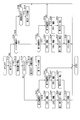
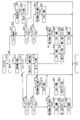
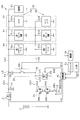
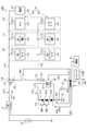
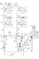
- FIG. 1 is an overall configuration diagram of the power supply system of the first embodiment.
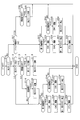
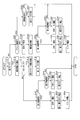
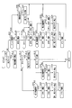
- FIG. 2 is a flowchart showing the procedure of the control process of the first embodiment.
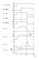
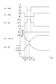
- FIG. 3 is a time chart showing an example of the control process of the first embodiment.
- FIG. 4 is a flowchart showing the procedure of the control process of the second embodiment.
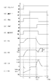
- FIG. 5 is a time chart showing an example of the control process of the second embodiment.
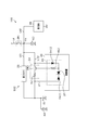
- FIG. 6 is an overall configuration diagram of the power supply system according to the third embodiment.
- FIG. 7 is a flowchart showing the procedure of the control process of the third embodiment.
- FIG. 8 is an overall configuration diagram of the power supply system according to the fourth embodiment.
- FIG. 9 is a flowchart showing the procedure of the control process of the fourth embodiment.
- FIG. 10 is an overall configuration diagram of the power supply system according to the fifth embodiment.
- FIG. 11 is a flowchart showing the procedure of the control process of the fifth embodiment.
- FIG. 12 is an overall configuration diagram of the power supply system in the modified example of the fifth embodiment.
- FIG. 13 is a flowchart showing the procedure of the control process in the modified example of the fifth embodiment.
- FIG. 14 is a flowchart showing the procedure of the control process of the sixth embodiment.
- FIG. 15 is an overall configuration diagram of the power supply system according to the seventh embodiment.
- FIG. 16 is a flowchart showing the procedure of the control process of the seventh embodiment.
- FIG. 17 is a time chart showing an example of the control process of the seventh embodiment.
- FIG. 18 is an overall configuration diagram of the power supply system in the modified example of the seventh embodiment.
- FIG. 19 is an overall configuration diagram of the power supply system according to the eighth embodiment.
- FIG. 20 is a flowchart showing the procedure of the control process of the eighth embodiment.
- FIG. 21 is a flowchart showing a procedure of control processing in the modified example of the eighth embodiment.
- the power supply system 100 is a system that supplies electric power to a general load 30 and a specific load 32.
- the power supply system 100 includes a high-voltage storage battery 10, a first DCDC converter (hereinafter, first converter) 12, a first storage battery 14, a second storage battery 16, a switch unit 20, and a second DCDC converter (hereinafter, second converter). 26 and a control device 40 are provided.
- the high-voltage storage battery 10 has a higher rated voltage (for example, several hundred volts) than the first storage battery 14 and the second storage battery 16, and is, for example, a lithium ion storage battery.
- the first converter 12 is a voltage generation unit that converts the electric power supplied from the high-voltage storage battery 10 into the electric power of the power supply voltage VA and supplies it to the general load 30 and the specific load 32.
- the power supply voltage VA is a voltage that enables driving of the general load 30 and the specific load 32.
- the general load 30 is an electric load (hereinafter, simply a load) that is not used for operation control in a vehicle as a mobile body, and is, for example, an air conditioner, an audio device, a power window, or the like.
- the specific load 32 is a load that performs at least one function used for driving control of the vehicle, for example, an electric power steering device 50 that controls the steering of the vehicle, an electric brake device 51 that applies a braking force to the wheels, and the like. It is a traveling control device 52 or the like that monitors the situation around the vehicle.
- the specific load 32 corresponds to the "electric load”
- the electric power steering device 50 corresponds to the "steering load”.
- the specific load 32 has a first load 34 and a second load 36 redundantly provided for each function so that all the functions are not lost even if an abnormality occurs.
- the electric power steering device 50 has a first steering motor 50A and a second steering motor 50B.
- the electric brake device 51 has a first brake device 51A and a second brake device 51B.
- the travel control device 52 has a camera 52A and a laser radar 52B.
- the first steering motor 50A, the first brake device 51A, and the camera 52A correspond to the first load 34
- the second steering motor 50B, the second brake device 51B, and the laser radar 52B correspond to the second load 36. ..
- the first load 34 and the second load 36 together realize one function, but each of them can realize a part of the function by itself.
- the first steering motor 50A and the second steering motor 50B allow the vehicle to be freely steered, and each steering motor 50A is subject to certain restrictions such as steering speed and steering range. , 50B enables steering of the vehicle.
- Each specific load 32 realizes a function of supporting control by the driver in manual operation. Further, each specific load 32 realizes a function required for automatic driving in automatic driving that automatically controls behavior such as running and stopping of the vehicle. Therefore, the specific load 32 can also be said to be a load that performs at least one function necessary for driving the vehicle.
- the first load 34 is connected to the first converter 12 via the path LA1 in the first system, and the first storage battery 14 and the general load 30 are connected to the path LA1 in the first system.
- the first storage battery 14 is connected to the path LA1 in the first system by a predetermined connector terminal.
- the first storage battery 14 is, for example, a lead storage battery, and is configured to be rechargeable by the power supply voltage VA of the first converter 12.
- the first system ES1 is configured by the first converter 12, the first storage battery 14, the general load 30, and the first load 34 connected by the path LA1 in the first system.
- the high-voltage storage battery 10 and the first converter 12 correspond to the "first power source”
- the first storage battery 14 corresponds to the "first power source and the first system storage battery”.
- the second load 36 is connected to the second storage battery 16 via the path LA2 in the second system.
- the second storage battery 16 is, for example, a lithium ion storage battery.
- the second system ES2 is configured by the second storage battery 16 and the second load 36 connected by the path LA2 in the second system.
- the second storage battery 16 corresponds to the "second power source, storage battery, second system storage battery".
- the switch unit 20 is provided in the connection path LB that connects each system to each other.
- One end of the connection path LB is connected to the first intra-system path LA1 at the connection point PA, and the other end of the connection path LB is connected to the second intra-system path LA2 at the connection point PB.
- the switch unit 20 includes a first switching element (hereinafter, simply the first switch) SW1.
- a first switching element hereinafter, simply MOSFET
- MOSFET N-channel MOSFET
- the first switch SW1 corresponds to an "intersystem switch".
- connection path LB is provided with a current detection unit 28.
- the current detection unit 28 is provided in the portion of the connection path LB on the first system ES1 side of the switch unit 20, and detects the magnitude and direction of the inter-system current IA flowing in the portion.
- the second converter 26 is provided in the path LA2 in the second system. Specifically, the second converter 26 is provided between the connection point PB with the connection path LB and the second storage battery 16 in the second system internal path LA2, and is supplied with electric power from the first converter 12.
- the second storage battery 16 is charged by converting power to a voltage higher than the power supply voltage VA. That is, the second storage battery 16 is a storage battery that can be charged by the power supply voltage VA of the first converter 12.
- the second converter 26 corresponds to the "charging unit".
- the control device 40 generates a first switching signal SC1 in order to switch the first switch SW1 based on the detection value of the current detection unit 28, and outputs a command from the first switching signal SC1 to the first switch SW1. .. Further, the control device 40 generates the first and second control signals SD1 and SD2 in order to control the operation of the first and second converters 12 and 26, and issues commands from the first and second control signals SD1 and SD2. 1, Output to the second converters 12 and 26. The operation state and the operation stop state of the first and second converters 12 and 26 are switched by the first and second control signals SD1 and SD2.
- control device 40 is connected to the notification unit 44, the IG switch 45, and the input unit 46, and controls these.
- the notification unit 44 is a device that visually or audibly notifies the driver, and is, for example, a display or a speaker installed in a vehicle interior.
- the IG switch 45 is a vehicle start switch.
- the control device 40 monitors the opening or closing of the IG switch 45.
- the input unit 46 is a device that accepts the operation of the driver, for example, a handle, a lever, a button, a pedal, and a voice input device.
- the control device 40 manually drives and automatically drives the vehicle using the above-mentioned specific load 32.
- the control device 40 includes a well-known microcomputer including a CPU, ROM, RAM, flash memory, and the like.
- the CPU realizes various functions for manual operation and automatic operation by referring to the arithmetic program and control data in the ROM.
- manual driving represents a state in which the vehicle is controlled by the operation of the driver.
- automatic driving represents a state in which the vehicle is driven and controlled by the control content by the control device 40 regardless of the operation of the driver.
- automatic driving refers to automatic driving of level 3 or higher among the automatic driving levels from level 0 to level 5 defined by the National Highway Traffic Safety Administration (NHTSA).
- Level 3 is a level at which the control device 40 controls both steering wheel operation and acceleration / deceleration while observing the traveling environment.
- control device 40 can implement a driving support function such as LKA (Lane Keeping Assist), LCA (Lane Change Assist), PCS (Pre-Crash Safety) by using the specific load 32 described above.
- the control device 40 can switch the driving mode of the vehicle between a first mode in which the driving support function is used and a second mode in which the driving support function is not used, and the vehicle can travel in each driving mode. ..
- the control device 40 switches between the first mode and the second mode according to the driver switching instruction via the input unit 46.
- the first mode includes a mode in which the driver manually drives the vehicle using the driving support function, and a mode in which the vehicle is automatically driven.
- the second mode is a mode in which the driver manually drives the vehicle without using the driving support function.
- the control device 40 determines whether or not an abnormality has occurred in the first system ES1 and the second system ES2, and if it is determined that no abnormality has occurred in any of the systems ES1 and ES2,
- the first load 34 and the second load 36 are used to automatically drive the vehicle and support driving.
- the first and second loads 34 and 36 cooperate to carry out one function necessary for automatic driving and driving support.
- the abnormality is a power failure abnormality such as a ground fault or a disconnection.
- the first switch SW1 is opened to electrically insulate the first system ES1 and the second system ES2.
- the loads 34 and 36 of the other system ES1 and ES2 in which the abnormality has not occurred can be driven.
- the first path LC1 and the second path LC2 provided in parallel with each other between the connection point PB with the connection path LB in the second system ES2 and the second storage battery 16 are provided.
- the first path LC1 is provided with the above-mentioned second converter 26, and the second converter 26 charges the second storage battery 16 at a voltage higher than the power supply voltage VA by supplying power from the first converter 12. ..
- the second converter 26 is a one-way power conversion circuit having only a booster circuit that boosts the power supply voltage VA and charges the second storage battery 16.
- the second path LC2 is provided with a switch unit 24.
- the switch unit 20 is referred to as a first switch unit 20, and the switch unit 24 is referred to as a second switch unit 24.
- the second switch unit 24 includes a second switching element (hereinafter, simply a second switch) SW2 that opens or closes the second system ES2.
- a MOSFET is used as the second switch SW2.
- the control device 40 generates a second switching signal SC2 in order to switch the second switch SW2, and outputs a command from the second switching signal SC2 to the second switch SW2.
- the second switch unit 24 corresponds to the “discharge control unit”
- the second switch SW2 corresponds to the “battery switch”.
- the second switch unit 24 is used to carry out a control process for restricting the discharge of the second storage battery 16 in the second path LC2.
- the second switch unit 24 is provided in parallel with the second converter 26, even if the voltage of the second storage battery 16 is higher than the power supply voltage VA, it is unnecessary from the second storage battery 16. Discharge is regulated. As a result, in the power supply system 100 having a plurality of power supply systems, it is possible to properly supply power to the loads 34 and 36.
- FIG. 2 shows a flowchart of the control process of the present embodiment.
- the control device 40 When the IG switch 45 is closed, the control device 40 repeatedly executes the control process at predetermined control cycles. At the beginning of closing the IG switch 45, the driving mode of the vehicle is set to the second mode. Further, the first switch SW1 is closed, the second switch SW2 is open, and the first and second converters 12 and 26 are in the operating state.
- step S10 it is determined whether or not the driving mode of the vehicle is the second mode. If affirmative determination is made in step S10, the remaining capacity SA of the second storage battery 16 is calculated in step S12.
- the remaining capacity SA is, for example, an SOC (State Of Charge) indicating the state of charge of the second storage battery 16.
- SOC State Of Charge
- the remaining capacity SA is calculated by using the current integrated value which is the time integrated value of the charge / discharge current of the second storage battery 16.
- step S14 it is determined whether or not the remaining capacity SA calculated in step S12 is larger than the predetermined capacity threshold value Sth.
- the capacity threshold Sth is a capacity in which the voltage of the second storage battery 16 is higher than the power supply voltage VA by a predetermined value or more.
- the remaining capacity SA of the second storage battery 16 is smaller than the capacity threshold value Sth, the voltage of the second storage battery 16 is not higher than the power supply voltage VA by a predetermined value or more, and the precondition for executing the first mode is not satisfied.
- a negative determination is made in step S14, and the process proceeds to steps S42 and S44.
- step S14 the second converter 26 is controlled so as to be appropriately switched between an operating state (charging state) and an operating stopped state (charging stopped state) according to the remaining capacity SA of the second storage battery 16.
- step S18 the operation mode of the vehicle is allowed to be switched from the second mode to the first mode, and the control process is terminated.
- the switching to the first mode is performed, for example, when a switching instruction such as an instruction to use the driving support function or an instruction for automatic driving is input from the driver via the input unit 46.
- a switching instruction such as an instruction to use the driving support function or an instruction for automatic driving is input from the driver via the input unit 46.
- the process of step S18 corresponds to the "mode control unit".
- step S10 it is determined in step S20 whether the driver is being notified.
- the driver notification notifies the driver that an abnormality has occurred in either the first system ES1 or the second system ES2, informs the driver that the first mode is to be canceled, and switches to the second mode. Is to encourage.
- step S20 If a negative determination is made in step S20, it is determined that an abnormality has occurred in either the first system ES1 or the second system ES2 in steps S22 and S24. Specifically, in step S22, it is determined whether or not an abnormality has occurred in the first system ES1. If a negative determination is made in step S22, it is determined in step S24 whether or not an abnormality has occurred in the second system ES2. In this embodiment, the process of step S22 corresponds to the "abnormality determination unit".
- the occurrence of an abnormality can be determined by the magnitude and direction of the inter-system current IA detected by the current detection unit 28.
- the direction of the inter-system current IA detected by the current detection unit 28 is the direction from the second system ES2 to the first system ES1, and is detected by the current detection unit 28.
- the magnitude of the inter-system current IA to be performed is equal to or larger than a predetermined current threshold value Is for determining a ground fault. Therefore, the current flowing through the first system ES1 becomes equal to or higher than the current threshold value Is.
- the direction of the inter-system current IA detected by the current detection unit 28 is the direction from the first system ES1 to the second system ES2, and the current detection unit 28 detects the inter-system current IA.
- the magnitude of the detected inter-system current IA is equal to or greater than the current threshold value Is. Therefore, the current flowing through the second system ES2 becomes equal to or higher than the current threshold value Is. Therefore, it is possible to determine which system ES1 or ES2 the abnormality has occurred based on the magnitude and direction of the inter-system current IA detected by the current detection unit 28.
- step S24 If it is determined that no abnormality has occurred in any of the systems ES1 and ES2, a negative determination is made in step S24. In this case, the control process is terminated. As a result, the first switch SW1 is maintained in the closed state, and the second switch SW2 is maintained in the open discharge regulation state. As a result, unnecessary discharge from the second storage battery 16 is restricted.
- step S26 the first switch SW1 is opened.
- step S28 the second switch SW2 is closed and the discharge restriction of the second path LC2 is released. That is, when it is determined that an abnormality has occurred in the first system ES1, the second switch SW2 is closed after the first switch SW1 is opened. As a result, the power supply from the second storage battery 16 to the second load 36 via the second path LC2 is secured.
- step S30 a command to put the first and second converters 12 and 26 into the operation stop state is output.
- the process of step S26 corresponds to the "state control unit".
- step S24 if an affirmative determination is made in step S24, first, in step S32, the first switch SW1 is opened. As a result, the power supply from the first converter 12 to the first load 34 in the first system ES1 is continued. In the following step S34, a command to put the second converter 26 into the operation stop state is output.
- step S36 the driver is notified via the notification unit 44 that the first mode is to be stopped, and the control process is terminated.
- step S38 it is determined in step S38 whether or not a switching instruction to the second mode has been input from the driver via the input unit 46. That is, it is determined whether or not there is a response from the driver in response to the notification. If a negative determination is made in step S38, the control process is terminated, and the running of the vehicle in the first mode is continued using the loads 34 and 36 on the system side where no abnormality has occurred.
- step S38 the driving mode of the vehicle is switched from the first mode to the second mode in step S40, and the control process is terminated.
- steps S42 and S44 that is, when the driving mode of the vehicle is the second mode, it is determined that an abnormality has occurred in either the first system ES1 or the second system ES2. Specifically, in step S42, it is determined whether or not an abnormality has occurred in the first system ES1. If a negative determination is made in step S42, it is determined in step S44 whether or not an abnormality has occurred in the second system ES2.
- step S44 If it is determined that no abnormality has occurred in any of the systems ES1 and ES2, a negative determination is made in step S44. In this case, the control process is terminated and the vehicle continues to run in the second mode.
- steps S46 to S52 when it is determined that an abnormality has occurred in either of the systems ES1 and ES2, in the following steps S46 to S52, the power supply to the system side where the abnormality has occurred is stopped, and the system in which the abnormality has not occurred is stopped. The process of continuing the power supply to the electric load of is carried out. Since the processes of steps S46 to S52 are the same as the processes of steps S26 to S36, the description thereof will be omitted.
- FIG. 3 shows an example of control processing.
- FIG. 3 shows the power supply voltage VA when a ground fault abnormality (hereinafter, simply ground fault) occurs in the first system ES1 while the vehicle is running in the first mode, and the load voltage VD applied to the second load 36. Shows the transition with.
- a ground fault abnormality hereinafter, simply ground fault
- FIG. 3 shows the transition of the state of the IG switch 45
- (B) shows the transition of the driving mode of the vehicle
- (C) shows the transition of the open / closed state of the first switch SW1.
- (D) shows the transition of the open / closed state of the second switch SW2.
- (E) shows the transition of the operating state of the second converter 26
- (F) shows the transition of the power supply voltage VA in the first converter 12
- (G) shows the transition of the load voltage VD in the second load 36. Shows the transition of.
- (H) shows the transition of the inter-system current IA
- (I) shows the transition of the remaining capacity SA of the second storage battery 16. Note that FIG. 3H shows the transition of the inter-system current IA with the inter-system current IA flowing from the second system ES2 to the first system ES1 as the positive direction.
- the first and second switches SW1 and SW2 are open during the open period of the IG switch 45 until the time t1, that is, in the hibernation state of the power supply system 100, and the first and second converters 12, 26 has been switched to the stopped operation state. Therefore, during the open period of the IG switch 45, the load voltage VD and the inter-system current IA become zero.
- the first switch SW1 When the IG switch 45 is closed at time t1, the first switch SW1 is closed and a command for switching the first and second converters 12 and 26 to the operating state is output. As a result, the first converter 12 is switched to the operating state, the power supply voltage VA and the load voltage VD rise to the predetermined operating voltage VM, and the vehicle can run in the second mode.
- the operating voltage VM is a voltage within the drive voltage range of the first and second loads 34 and 36.
- the second converter 26 is switched to the operating state, and the second storage battery 16 is charged by the power supply voltage VA of the first converter 12.
- the voltage of the second storage battery 16 rises to a predetermined boosted voltage VH (see FIG. 3G), which is higher than the power supply voltage VA.
- the operation mode of the vehicle can be switched from the second mode to the first mode at time t2.
- the second converter 26 is maintained in the operating state even after switching to the first mode, and the charging of the second storage battery 16 is continued.
- the charging current of the second storage battery 16 decreases as the remaining capacity SA increases, and the magnitude of the inter-system current IA decreases. Then, when the remaining capacity SA is fully charged, the charging of the second storage battery 16 is temporarily stopped.
- the first switch SW1 is maintained in the closed state.
- electric power can be supplied from the first converter 12 and the first storage battery 14 to the first and second loads 34 and 36, respectively.
- the power supply from the first converter 12 enables continuous power supply even during long-term automatic operation, and the power supply from the first storage battery 14 enables power supply with less voltage fluctuation.
- automatic operation and driving support using the first load 34 and the second load 36 are performed.
- the first switch SW1 is closed.
- a ground fault occurs in the first system ES1 at time t3.
- the power supply voltage VA and the load voltage VD decrease. Due to the inductance component of the connection path LB, the rate of decrease of the load voltage VD is smaller than the rate of decrease of the power supply voltage VA.
- the inter-system current IA increases, and at the subsequent time t4, the inter-system current IA becomes equal to or higher than the current threshold value Is. As a result, it is determined that a ground fault has occurred in the first system ES1. In this case, at time t4, the first switch SW1 is opened and the first converter 12 is switched to the operation stop state. This reduces the inter-system current IA.
- the driving mode of the vehicle is switched from the first mode to the second mode at time t5.
- the first path LC1 and the second path LC2 are provided in parallel with each other between the connection point PB with the connection path LB in the second system ES2 and the second storage battery 16.
- the second converter 26 charges the second storage battery 16 with a voltage higher than the power supply voltage VA of the first converter 12 by the power supply from the first converter 12.
- the discharge of the second storage battery 16 in the second system ES2 is regulated by the second switch unit 24.
- the second storage battery 16 when the power is supplied from the second storage battery 16 in the second system ES2 due to the occurrence of an abnormality in the first system ES1, the second storage battery 16 is charged to a voltage higher than the power supply voltage VA. Therefore, the second load 36 can be properly operated even in a low temperature environment. Further, since the second switch unit 24 is provided in parallel with the second converter 26, even if the second storage battery 16 has a voltage higher than the power supply voltage VA, unnecessary discharge from the second storage battery 16 is generated. Be regulated. As a result, in the power supply system 100 having a plurality of power supply systems, it is possible to properly supply power to the loads 34 and 36.
- the second switch SW2 is provided in the second switch unit 24, and the first switch SW1 and the second switch SW2 are linked to open and close each of them based on the presence or absence of an abnormality in the first system ES1. I made it.
- the discharge of the second storage battery 16 can be properly managed both when the first system ES1 is normal and when an abnormality occurs in the first system ES1.
- the first switch SW1 When it is determined that an abnormality has occurred in the first system ES1, the first switch SW1 is opened and the second switch SW2 is closed, and the second storage battery 16 is transferred to the second load 36 in the second system ES2. Power will be supplied. Of these, if the second switch SW2 is closed first and the first switch SW1 is opened later, there is a concern that power will be wastedly supplied from the second storage battery 16 to the first system ES1 in which the abnormality has occurred. .. In that respect, in the present embodiment, when an abnormality occurs in the first system ES1, the second switch SW2 is closed after the first switch SW1 is opened, so that the power is supplied from the second storage battery 16 to the first system ES1. Can be suppressed, and power can be properly supplied to the second load 36.
- the first load 34 and the second load 36 are functions necessary for driving the vehicle and are loads for implementing the driving support function. Then, it is possible to switch between traveling in the first mode using the driving support function and traveling in the second mode without using the driving support function.
- the remaining capacity SA of the second storage battery 16 is larger than the capacity threshold value Sth, which is the capacity at which the voltage of the second storage battery 16 is higher than the power supply voltage VA by a predetermined value or more.
- the driving mode is allowed to be switched from the second mode to the first mode. Therefore, even if an abnormality occurs in the first system ES1 after the transition to the first mode, an appropriate fail-safe process after that can be performed.
- the present embodiment differs from the first embodiment in that when it is determined that an abnormality has occurred in the first system ES1 in the first mode, the second switch SW2 is closed and then the first switch SW1 is opened. ..
- the control device 40 has a second current threshold value Is2 set to a value smaller than the first current threshold value Is1 which is the current threshold value Is for determining the ground fault. Then, in the control process, the second switch SW2 is closed by using the second current threshold value Is2, and the first switch SW1 is opened by using the second current threshold value Is2.
- the first current threshold value Is1 corresponds to the "first threshold value”
- the second current threshold value Is2 corresponds to the "second threshold value”.
- FIG. 4 shows a flowchart of the control process of the present embodiment.
- the same processing as that shown in FIG. 2 above is given the same step number for convenience, and the description thereof will be omitted.
- step S20 if a negative determination is made in step S20, it is determined in step S60 whether or not the magnitude of the intersystem current IA detected by the current detection unit 28 is equal to or greater than the second current threshold value Is2. If a negative determination is made in step S60, the control process ends. On the other hand, if an affirmative determination is made in step S60, it is determined in step S62 whether or not the magnitude of the inter-system current IA is equal to or greater than the first current threshold value Is1.
- step S62 If the magnitude of the inter-system current IA is equal to or greater than the second current threshold value Is2 and smaller than the first current threshold value Is1, a negative determination is made in step S62. In this case, in step S64, it is determined whether or not the direction of the inter-system current IA detected by the current detection unit 28 is the direction from the second system ES2 to the first system ES1.
- step S64 If the direction of the inter-system current IA detected by the current detection unit 28 is the direction from the first system ES1 to the second system ES2, a negative determination is made in step S64, and the control process is terminated.
- the current flowing through the first system ES1 is smaller than the first current threshold value Is1.
- the second current threshold is Is2 or higher. In this case, an affirmative determination is made in step S64, and in step S66, the second switch SW2 is closed to end the control process.
- step S62 when the magnitude of the inter-system current IA is equal to or greater than the first current threshold value Is1, a positive determination is made in step S62. In this case, in step S68, it is determined whether or not the direction of the inter-system current IA detected by the current detection unit 28 is the direction from the second system ES2 to the first system ES1.
- step S68 When the direction of the inter-system current IA detected by the current detection unit 28 is the direction from the first system ES1 to the second system ES2, the current flowing through the first system ES1 becomes the first current threshold value Is1 or more. In this case, it is determined that an abnormality has occurred in the first system ES1, an affirmative determination is made in step S68, and the process proceeds to step S26.
- step S68 when the direction of the inter-system current IA detected by the current detection unit 28 is the direction from the second system ES2 to the first system ES1, the current flowing through the second system ES2 becomes the first current threshold value Is1 or more. .. In this case, it is determined that an abnormality has occurred in the second system ES2, a negative determination is made in step S68, and the process proceeds to step S32.
- step S14 the processes of steps S70 to S78 and the like are carried out. Since the processes of steps S70 to S78 are the same as the processes of steps S60 to S68, the description thereof will be omitted.
- FIG. 5 shows the transition between the power supply voltage VA and the load voltage VD applied to the second load 36 when a ground fault occurs in the first system ES1 while the vehicle is running in the first mode. Since (A) to (I) in FIG. 5 are the same as (A) to (I) in FIG. 3, the description thereof will be omitted. Further, in FIG. 5, the processing up to the time t3 is the same as the processing shown in FIG. 3, and therefore the description thereof will be omitted.
- the second switch SW2 is closed at time t11. That is, the second switch SW2 is closed before the first switch SW1 is opened, and the power supply from the second storage battery 16 to the second load 36 via the second path LC2 is started. As a result, as shown by the broken line in FIG. 5 (G), the power supply to the second load 36 is temporarily cut off as in the case where the second switch SW2 is closed after the first switch SW1 is opened. Therefore, it is suppressed that the load voltage VD is lower than the threshold voltage Vth.
- the inter-system current IA becomes equal to or higher than the first current threshold value Is1 at the subsequent time t4, it is determined that a ground fault has occurred in the first system ES1.
- the first switch SW1 is opened and the first and second converters 12 and 26 are switched to the operation stop state.
- the first switch SW1 When it is determined that an abnormality has occurred in the first system ES1, the first switch SW1 is opened and the second switch SW2 is closed, and the second storage battery 16 to the second load 36 are performed in the second system ES2.
- the first switch SW1 When the first switch SW1 is opened first and the second switch SW2 is closed later, the power supply to the second load 36 is temporarily cut off. There is a concern that it will end up.
- the first switch SW1 is opened after the second switch SW2 is closed, so that the interruption of the power supply to the second load 36 is suppressed. This makes it possible to properly supply power to the second load 36.
- an inter-system current IA having a magnitude of the first current threshold Is1 or more flows in the direction from the first system ES1 to the second system ES2, and the current flowing through the first system ES1 is the first current threshold Is1 or more.
- the first switch SW1 is released.
- an inter-system current IA having a magnitude of the second current threshold value Is2 or more flows in the direction from the first system ES1 to the second system ES2, and the current flowing through the first system ES1 is smaller than the first current threshold value Is1.
- the second switch SW2 is closed when the current threshold value Is2 or more is reached.
- the first switch SW1 and the second switch SW2 can be appropriately linked to open and close each other.
- the second switch unit 24 includes first to third diodes DA1 to DA3 connected in series with each other.
- the diodes DA1 to DA3 are arranged so that the cathode is on the connection point PB side with the connection path LB and the anode is on the second storage battery 16 side, and the connection point PB to the second storage battery 16 in the second path LC2. Regulate the flow of current.
- each diode DA1 to DA3 has a predetermined forward voltage drop amount (for example, 0.7V). Therefore, between the voltage of the second storage battery 16 applied to the second storage battery 16 side of the second switch unit 24 and the power supply voltage VA of the first converter 12 applied to the connection point PB side of the second switch unit 24. In addition, a voltage difference due to the total value of the forward voltage drops of the first to third diodes DA1 to DA3 (hereinafter, voltage difference due to the first to third diodes DA1 to DA3) is generated.
- a voltage difference due to the first to third diodes DA1 to DA3 (hereinafter, voltage difference due to the first to third diodes DA1 to DA3) is generated.
- the voltage difference between the first to third diodes DA1 to DA3 is set to be larger than the voltage difference between the voltage of the second storage battery 16 and the power supply voltage VA in the normal state of the first system ES1.
- the voltage difference between the first to third diodes DA1 to DA3 is set to be larger than the voltage difference between the boosted voltage VH of the second storage battery 16 and the operating voltage VM which is the power supply voltage VA. .. Therefore, in the normal state of the first system ES1, the current flow from the connection point PB to the second storage battery 16 as well as the current flow from the second storage battery 16 to the connection point PB are regulated in the second path LC2. ..
- the series connection body of the first to third diodes DA1 to DA3 corresponds to the "rectifying element".
- a third switching element (hereinafter, simply a third switch) SW3 is provided between the connection points of the first and second paths LC1 and LC2 on the second storage battery 16 side and the second storage battery 16.
- a MOSFET is used as the third switch SW3.
- the control device 40 generates a third switching signal SC3 in order to switch the third switch SW3, and outputs a command from the third switching signal SC3 to the third switch SW3.
- FIG. 7 shows a flowchart of the control process of the present embodiment.
- the same processing as that shown in FIG. 2 above is given the same step number for convenience, and the description thereof will be omitted.
- the third switch SW3 is closed.
- step S22 if an affirmative determination is made in step S22, the first switch SW1 is released in step S26, and the process proceeds to step S30. Therefore, in the present embodiment, when an abnormality occurs in the first system ES1, the second storage battery 16 is discharged as the load voltage VD of the second system ES2 decreases. If an affirmative determination is made in step S24, the first and third switches SW1 and SW3 are opened in step S80, and the process proceeds to step S34.
- step S42 the process of step S46 or the like is performed, and if an affirmative determination is made in step S44, the process of step S82 or the like is executed. Since each process of steps S46 and S82 is the same process as each process of steps S26 and S80, the description thereof will be omitted.
- the first to third diodes DA1 to DA3 are provided as the second switch unit 24, and the first to third diodes DA1 to DA3 provide a connection path in the second path LC2.
- the flow of current from the connection point PB with the LB to the second storage battery 16 is regulated, and a predetermined voltage difference is generated between the voltage of the second storage battery 16 and the power supply voltage VA.
- discharge is regulated while maintaining a state in which the voltage is higher than the power supply voltage VA of the first converter 12.
- the second storage battery 16 is discharged as the load voltage VD decreases in the second system ES2, and it is possible to supply electric power to the second load 36 at an early stage. It has become.
- the second switch unit 24 provides the fourth and fifth switching elements (hereinafter, simply the fourth and fifth switches) SW4 and SW5, which are semiconductor switching elements having a parasitic diode. It differs from the third embodiment in that it is provided.
- MOSFETs are used as the fourth and fifth switches SW4 and SW5.
- the control device 40 generates the fourth and fifth switching signals SC4 and SC5 in order to switch the fourth and fifth switches SW4 and SW5, and commands the fourth and fifth switching signals SC4 and SC5. Is output to the 4th and 5th switches SW4 and SW5.
- a fourth diode DA4 is connected in parallel to the fourth switch SW4 as a parasitic diode
- a fifth diode DA5 is connected in parallel to the fifth switch SW5 as a parasitic diode.
- the fourth and fifth switches SW4 and SW5 are connected in series so that the directions of the fourth and fifth diodes DA4 and DA5 are equal to each other.
- the diodes DA4 and DA5 are arranged so that the cathode is on the connection path LB side and the anode is on the second storage battery 16 side.
- the fourth and fifth diodes DA4 and DA5 regulate the flow of current from the connection point PB to the second storage battery 16 in the second path LC2. That is, in the present embodiment, the rectifying element that regulates the flow of current from the connection point PB to the second storage battery 16 in the second path LC2 is configured by the parasitic diode. Then, in the present embodiment, the voltage difference due to the fourth and fifth diodes DA4 and DA5 is set to be larger than the voltage difference between the voltage of the second storage battery 16 and the power supply voltage VA in the normal state of the first system ES1. Has been done.
- the parasitic diode has a larger amount of heat generated by energization than a single diode element. Therefore, when an abnormality occurs in the first system ES1, there is a concern that the temperature of the fourth and fifth switches SW4 and SW5 will rise excessively due to the energization of the fourth and fifth diodes DA4 and DA5. Therefore, in the present embodiment, in the control process, when an abnormality occurs in the first system ES1, the fourth and fifth switches SW4 and SW5 are closed, and the fourth and fifth switches SW4 and SW5 are brought into a conductive state. ..
- FIG. 9 shows a flowchart of the control process of the present embodiment.
- the same processes as those shown in FIGS. 2 and 7 above are designated with the same step numbers for convenience, and the description thereof will be omitted.
- the fourth and fifth switches SW4 and SW5 are closed.
- step S22 if an affirmative determination is made in step S22, the first switch SW1 is opened in step S26.
- step S84 the fourth and fifth switches SW4 and SW5 are closed, and the process proceeds to step S30. Therefore, in the 4th and 5th switches SW4 and SW5, a current flows through the 4th and 5th diodes DA4 and DA5 immediately after the abnormality occurs in the 1st system ES1. After that, when the 4th and 5th switches SW4 and SW5 are closed, a current flows through the 4th and 5th switches SW4 and SW5.
- step S86 is performed. Since each process of step S86 is the same process as each process of step S84, the description thereof will be omitted.
- the parasitic diode of the fourth and fifth switches SW4 and SW5 is used as the rectifying element. Therefore, when an abnormality occurs in the first system ES1, power can be supplied from the second storage battery 16 to the second load 36 via the fourth and fifth diodes DA4 and DA5, which are parasitic diodes. There is concern about heat generation of the 4th and 5th diodes DA4 and DA5. In this respect, in the present embodiment, when an abnormality occurs in the first system ES1, the fourth and fifth switches SW4 and SW5 are closed, so that the second load 36 can be supplied with electric power at an early stage. The heat generation of the fourth and fifth diodes DA4 and DA5 can be suppressed.
- the present embodiment is different from the third embodiment in that the second path LC2 is composed of the first regulated path LD1 and the second regulated path LD2 provided in parallel with each other. That is, in the present embodiment, the first path LC1, the first regulated path LD1 and the second regulated path LD2 are arranged in parallel between the connection point PB with the connection path LB in the second system ES2 and the second storage battery 16. It is provided.
- the first regulation path LD1 is provided with the first to third diodes DA1 to DA3 and the sixth switching element (hereinafter, simply the sixth switch) SW6 connected in series.
- the first to third diodes DA1 to DA3 are provided on the connection path LB side of the sixth switch SW6.
- the second regulation path LD2 is provided with a seventh switching element (hereinafter, simply the seventh switch) SW7.
- the second switch section 24 is composed of the first to third diodes DA1 to DA3 and the sixth and seventh switches SW6 and SW7.
- the sixth switch SW6 corresponds to the "second regulation switch”
- the seventh switch SW7 corresponds to the "regulation switch, the first regulation switch”.
- the sixth switch SW6 opens or closes the first regulation path LD1
- the seventh switch SW7 opens or closes the second regulation path LD2.
- MOSFETs are used as the 6th and 7th switches SW6 and SW7.
- the control device 40 generates the sixth and seventh switching signals SC6 and SC7 in order to switch the sixth and seventh switches SW6 and SW7, and commands the sixth and seventh switching signals SC6 and SC7. Is output to the 6th and 7th switches SW6 and SW7.
- a sixth diode DA6 is connected in parallel to the sixth switch SW6 as a parasitic diode, and a seventh diode DA7 is connected in parallel to the seventh switch SW7 as a parasitic diode.
- the diodes DA6 and DA7 are arranged so that the cathode is on the second storage battery 16 side and the anode is on the connection path LB side in each regulation path LD1 and LD2. Therefore, in the first regulation path LD1, the first to third diodes DA1 to DA3 and the sixth diode DA6 are provided so as to be in opposite directions.
- the seventh diode DA7 regulates the current flow from the second storage battery 16 to the connection point PB, and allows the current flow from the connection point PB to the second storage battery 16. It is provided in.
- the 7th diode DA7 corresponds to the "charge allowable portion".
- the second storage battery 16 is appropriately charged by the power supply voltage VA of the first converter 12. For example, when the voltage of the second storage battery 16 temporarily rises at the start of charging the second storage battery 16, the second storage battery 16 being charged is discharged via the first to third diodes DA1 to DA3. Is a concern.
- each diode DA1 to DA3 has a forward voltage drop amount
- the diodes DA1 to DA3 are in this order.
- the load voltage VD decreases depending on the amount of directional voltage drop. Further, there is a concern that the power consumption of the second storage battery 16 will increase due to this forward voltage drop amount. Therefore, in the present embodiment, in the control process, the opening and closing of the sixth and seventh switches SW6 and SW7 are appropriately switched.
- FIG. 11 shows a flowchart of the control process of the present embodiment.
- the same processes as those shown in FIGS. 2 and 7 above are designated with the same step numbers for convenience, and the description thereof will be omitted.
- step S14 if an affirmative determination is made in step S14, the second converter 26 is switched to the operation stop state (charging stop state) in step S16.
- step S88 the sixth switch SW6 is closed and the seventh switch SW7 is opened, and the process proceeds to step S18. That is, when it is determined that no abnormality has occurred in any of the systems ES1 and ES2 and the second storage battery 16 is not charged, the sixth switch SW6 is closed.
- step S90 it is determined in step S90 whether or not the first switch SW1 is open. If a negative determination is made in step S90, the first switch SW1 is opened in step S92. In the following step S92, the seventh switch SW7 is closed. That is, when it is determined that an abnormality has occurred in the first system ES1, the second switch SW2 is closed after the first switch SW1 is opened. In the following step S30, a command to put the first and second converters 12 and 26 into the operation stop state is output, and the control process is terminated.
- step S90 determines whether the processes of steps S92 to S96 have already been performed. If an affirmative determination is made in step S90, that is, if the processes of steps S92 to S96 have already been performed, the sixth switch SW6 is released in step S98, and the process proceeds to step S36. Therefore, the sixth switch SW6 is opened after the seventh switch SW7 is closed.
- step S44 if a negative determination is made in step S44, the sixth switch SW6 and the seventh switch SW7 are opened and the control process is terminated in step S99. That is, when it is determined that no abnormality has occurred in any of the systems ES1 and ES2 and the second storage battery 16 is charged, the sixth switch SW6 is opened.
- step S42 the processes of steps S100 to 108 are carried out. Since each process of steps S100 to 108 is the same process as each process of steps S90 to 98, the description thereof will be omitted.
- the first to third diodes DA1 to DA3 are used as a configuration for restricting the discharge of the second storage battery 16 in the second path LC2. Therefore, when an abnormality occurs in the first system ES1, power can be supplied from the second storage battery 16 to the second load 36 via the first to third diodes DA1 to DA3, but the first to third diodes The load voltage VD decreases due to the amount of forward voltage drop of DA1 to DA3.
- the seventh switch SW7 is closed after the first switch SW1 is opened.
- the first switch SW1 When an abnormality occurs in the first system ES1, the first switch SW1 is first opened to enable early power supply to the second load 36 by the first to third diodes DA1 to DA3. Then, by closing the seventh switch SW7 after that, it is possible to suppress the voltage drop of the second load 36 due to the first to third diodes DA1 to DA3.
- the load voltage VD changes depending on the drive amount of the loads 34 and 36. Therefore, for example, when the drive amount of the loads 34 and 36 temporarily decreases, the load voltage VD may increase excessively. When the load voltage VD rises excessively, it is desired that the overvoltage be absorbed by the second storage battery 16.
- the second converter 26 is provided in the first path LC1 and the first to third diodes DA1 to DA3 are provided in the second path LC2
- the second converter 26 and the first to third diodes DA1 to DA1 to are provided.
- the flow of current from the connection point PB to the second storage battery 16 via the DA3 is restricted, and the overvoltage in the load voltage VD cannot be absorbed by the second storage battery 16.
- the seventh diode DA7 connected in parallel to the seventh switch SW7 is provided in the second regulation path LD2 in which the first to third diodes DA1 to DA3 are not provided in the second path LC2. I made it.
- the seventh diode DA7 is provided so as to regulate the current flow from the second storage battery 16 to the connection point PB in the second regulation path LD2 and to allow the current flow from the connection point PB to the second storage battery 16. ing. Therefore, when the load voltage VD rises excessively in the state where the seventh switch SW7 is closed, the overvoltage can be absorbed by the second storage battery 16 via the seventh diode DA7.
- the 7th diode DA7 is connected in parallel to the 7th switch SW7, and the 7th diode DA7 is overvoltage when the load voltage VD exceeds the upper limit of the power supply voltage VA as the load voltage VD rises.
- the overvoltage can be absorbed by the second storage battery 16 via the above. Thereby, the loads 34 and 36 can be protected from the overvoltage.
- the overvoltage includes, for example, the driving of the electric power steering device 50 and the load dump of the first storage battery 14.
- the load voltage VD rises excessively and becomes an overvoltage state when the driving amount of the electric power steering device 50 temporarily decreases.
- the overvoltage can be absorbed by the second storage battery 16 via the seventh diode DA7.
- the first storage battery 14 was connected to the path LA1 in the first system by disconnecting the connector terminal connecting the first storage battery 14 and the path LA1 in the first system. It means the time of switching from the state to the disconnected state.
- the seventh switch is provided.
- the SW7 When the SW7 is open, the power supply by the second storage battery 16 is restricted, so that the first converter 12 and the first storage battery 14 perform redundant power supply. That is, according to the power supply from the first converter 12, continuous power supply is possible even during long-term operation, and according to the power supply from the first storage battery 14, power supply with small voltage fluctuation is possible. Become.
- the overvoltage can be absorbed by the second storage battery 16 via the seventh diode DA7.
- the second storage battery 16 When it is determined that no abnormality has occurred in the first system ES1, the second storage battery 16 is appropriately charged by the power supply voltage VA of the first converter 12, for example, when the charging of the second storage battery 16 is started. When the voltage of the second storage battery 16 temporarily rises, there is a concern that the second storage battery 16 being charged is discharged via the first to third diodes DA1 to DA3.
- the sixth switch SW6 connected in series to the first to third diodes DA1 to DA3 is provided. Then, when the second storage battery 16 is not charged, the sixth switch SW6 is closed, and when the second storage battery 16 is charged, the sixth switch SW6 is opened. That is, when the second storage battery 16 is not charged, discharge by the first to third diodes DA1 to DA3 is allowed, and when the second storage battery 16 is charged, the first to third diodes DA1 are allowed. -The discharge by DA3 is regulated. As a result, it is possible to suppress the discharge of the second storage battery 16 during charging while enabling the early power supply to the second load 36 by the first to third diodes DA1 to DA3.
- the seventh switch SW7 may be composed of the seventhA switch SW7A and the seventhB switch SW7B connected in series.
- the 7B switch SW7B is provided on the connection path LB side with respect to the 7A switch SW7A.
- MOSFETs are used as the 7A and 7B switches SW7A and SW7B.
- the control device 40 generates the 7A and 7B switching signals SC7A and SC7B in order to switch the 7A and 7B switches SW7A and SW7B in the control process, and commands the 7A and 7B switching signals SC7A and SC7B. Is output to the 7A and 7B switches SW7A and SW7B.
- the 7A switch SW7A corresponds to the "first changeover switch”
- the 7B switch SW7B corresponds to the "second changeover switch".
- the 7A diode DA7A is connected in parallel to the 7A switch SW7A as a parasitic diode
- the 7B diode DA7B is connected in parallel to the 7B switch SW7B as a parasitic diode.
- the 7A and 7B parasitic diodes DA7A and DA7B are connected in series so that the directions of the 7A and 7B parasitic diodes DA7A and DA7B are opposite to each other.
- the 7A parasitic diode DA7A is arranged so that the anode is on the connection path LB side and the cathode is on the second storage battery 16 side, and the 7B diode DA7B has the anode on the second storage battery 16 side and the cathode. It is arranged so as to be on the connection path LB side.
- the 7A parasitic diode DA7A corresponds to the "charge allowable portion".
- the second storage battery 16 is appropriately charged by the power supply voltage VA of the first converter 12, and the 7A and 7B switches SW7A are appropriately charged.
- SW7B regulates the charging of the second storage battery 16.
- the 7A diode DA7A is connected in parallel to the 7A switch SW7A
- the 7B switch SW7B is closed even if the 7A switch SW7A is open, the second is via the 7A diode DA7A.
- the storage battery 16 is charged. Therefore, there is a concern that the charging of the second storage battery 16 cannot be regulated by the 7A and 7B switches SW7A and SW7B. Therefore, in this modification, the opening and closing of the 7A and 7B switches SW7A and SW7B are appropriately switched in the control process.
- step S88 when the 7th switch SW7 is opened the 7A switch SW7A is opened and the 7B switch SW7B is closed. That is, when it is determined that no abnormality has occurred in any of the systems ES1 and ES2, and the second storage battery 16 is not charged, the 7A switch SW7A is opened and the 7B switch SW7B is closed. ..
- the overvoltage can be absorbed by the second storage battery 16 via the 7B switch SW7B and the 7A diode DA7A.
- step S99 in which the 7th switch SW7 is released the 7A and 7B switches SW7A and SW7B are opened. That is, when it is determined that no abnormality has occurred in any of the systems ES1 and ES2 and the second storage battery 16 is charged, the 7A and 7B switches SW7A and SW7B are opened. As a result, when the second storage battery 16 is being charged, charging via the 7A diode DA7A can be restricted. According to the present modification described in detail above, it is possible to properly implement the charging regulation of the second storage battery 16 while enabling the absorption of the overvoltage into the second storage battery 16.
- a boosting condition indicating that the voltage of the second storage battery 16 needs to be higher than the power supply voltage VA, that is, that the voltage of the second storage battery 16 needs to be increased is satisfied. It is different from the first embodiment in that the voltage is increased by the second converter 26. That is, in the present embodiment, the voltage of the second storage battery 16 is set to a voltage higher than the power supply voltage VA only when the boosting condition is satisfied. When the boosting condition is not satisfied, the second storage battery 16 is charged by the power supply voltage VA of the first converter 12 to a voltage equal to or lower than the power supply voltage VA. Therefore, the second converter 26 does not need to perform a boosting operation.
- the power supply system 100 is in a predetermined low temperature state, or the traveling mode of the vehicle is the first mode. Therefore, when the boosting condition is satisfied, when the traveling mode of the vehicle is the first mode, the traveling mode of the vehicle is first switched to the first mode, and then the voltage of the second storage battery 16 is increased. In that respect, it differs from the first embodiment.
- FIG. 14 shows a flowchart of the control process of the present embodiment.
- the same processing as that shown in FIG. 2 above is given the same step number for convenience, and the description thereof will be omitted.
- step S110 determines whether or not the second converter 26 is in the stopped state. For example, when the power supply system 100 is in a low temperature state and the switching instruction is not input by the driver, the operation mode of the vehicle is the second mode, and the second converter 26 is in the operating state. In this case, a negative determination is made in step S110, and the process proceeds to steps S42 and S44.
- step S110 it is determined in step S112 whether or not a switching instruction to the first mode has been input from the driver via the input unit 46. If affirmative determination is made in step S112, the driving mode of the vehicle is switched from the second mode to the first mode in step S114, and in step S116, a command for setting the second converter 26 to the operating state is output, and the control process is terminated. ..
- step S118 it is determined in step S118 whether or not the power supply system 100 is in a low temperature state.
- the low temperature state is a state in which the ambient temperature of the vehicle is zero degree or less. If a negative determination is made in step S118, the process proceeds to steps S42 and S44. On the other hand, if an affirmative determination is made in step S98, a command for setting the second converter 26 to the operating state is output in step S120, and the process proceeds to steps S42 and S44.
- steps S96 and S100 corresponds to the "boost control unit".
- the second storage battery 16 In a configuration in which the second storage battery 16 has a higher voltage than the power supply voltage VA of the first converter 12 due to the charging of the second converter 26, the second storage battery 16 to the second load 36 when an abnormality occurs in the first system ES1.
- the first system ES1 In a situation where the first system ES1 is maintained in a normal state, there is a concern that an excessive amount of electric energy is used.
- the boosting since the boosting is performed by the second converter 26 only when the boosting condition is satisfied and the second storage battery 16 is charged, it is possible to suppress excessive use of electric energy.
- the second storage battery 16 is formed by changing the degree of boosting performed by the second converter 26 according to the ambient temperature of the vehicle including the power supply system 100, such as when the power supply system 100 is in a low temperature state.
- the voltage of can be adjusted appropriately as needed.
- the first load 34 and the second load 36 are functions necessary for driving the vehicle and are loads for implementing the driving support function. Then, it is possible to switch between traveling in the first mode using the driving support function and traveling in the second mode without using the driving support function.
- the traveling mode of the vehicle is the first mode
- the voltage of the second storage battery 16 can be appropriately adjusted as necessary by boosting the voltage by the second converter 26 when the traveling mode of the vehicle is the first mode.
- the second switch unit 24 includes the eighth and ninth switching elements (hereinafter, simply the eighth and ninth switches) SW8 and SW9, which is different from the third embodiment. different.
- the eighth switch SW8 is connected in parallel to the first diode DA1
- the ninth switch SW9 is connected in parallel to the second diode DA2.
- the third diode DA3 is not provided with a switching element connected in parallel.
- MOSFETs are used as the 8th and 9th switches SW8 and SW9.
- the control device 40 generates the 8th and 9th switching signals SC8 and SC9 in order to switch the 8th and 9th switches SW8 and SW9 in the control process, and commands the 8th and 9th switching signals SC8 and SC9. Is output to the 8th and 9th switches SW8 and SW9.
- the voltage difference generated by the first to third diodes DA1 to DA3 is configured to be variable. Specifically, the voltage difference between the first to third diodes DA1 to DA3 can be switched by switching the opening and closing of the eighth and ninth switches SW8 and SW9.
- the eighth switch SW8 constitutes a path that bypasses the first diode DA1 by being closed. When the eighth switch SW8 is closed, the first diode DA1 becomes a non-conducting state, and the forward voltage drop amount of the first diode DA1 does not occur. On the other hand, when the eighth switch SW8 is opened, the first diode DA1 becomes conductive, and a forward voltage drop amount of the first diode DA1 occurs. As a result, the voltage difference between the first to third diodes DA1 to DA3 is switched. The same applies to the ninth switch SW9. In this embodiment, the 8th and 9th switches SW8 and SW9 correspond to "bypass switches”.
- the first and second voltage detection units 60 and 62 are provided.
- the first voltage detection unit 60 is connected to the connection point PB between the second system internal path LA2 and the connection path LB, and detects the load voltage VD as the voltage of the connection point PB.
- the second voltage detection unit 62 is connected to a portion of the path LA2 in the second system between the second storage battery 16 and the third switch SW3, and detects the storage battery voltage VB which is the voltage of the second storage battery 16. ..
- FIG. 16 shows a flowchart of the control process of the present embodiment.
- the same step number is assigned and the description thereof will be omitted for convenience.
- the 8th and 9th switches SW8 and SW9 are open.
- step S20 the difference DV, which is the voltage difference between the load voltage VD and the storage battery voltage VB, is calculated in step S130.
- the difference DV is calculated using the load voltage VD detected by the first voltage detection unit 60 and the storage battery voltage VB detected by the second voltage detection unit 62.
- step S132 the voltage difference between the first to third diodes DA1 to DA3 is switched based on the difference DV calculated in step S130. Specifically, it is determined whether or not the difference DV is larger than the predetermined first and second switching thresholds Dth1 and Dth2, and the voltage difference between the first to third diodes DA1 to DA3 is switched according to the determination result.
- the forward voltage drop amount of each diode DA1 to DA3 is VF
- the first switching threshold Dth1 is larger than twice the forward voltage drop amount VF, and is 3 of the forward voltage drop amount VF.
- the voltage difference is set to be less than double.
- the second switching threshold value Dth2 is set to a voltage difference larger than the forward voltage drop amount VF and smaller than twice the forward voltage drop amount VF.
- step S132 when the difference DV is larger than the first switching threshold value Dth1, the eighth and ninth switches SW8 and SW9 are opened.
- the eighth switch SW8 is closed and the ninth switch SW9 is opened.
- the eighth and ninth switches SW8 and SW9 are closed.
- step S132 corresponds to the "voltage difference switching unit".
- FIG. 17 shows an example of control processing.
- FIG. 17 shows the voltage due to the first to third diodes DA1 to DA3 when the drive amount of the loads 34 and 36 temporarily increases while the vehicle is running in the normal state of the first system ES1 in the first mode. The transition of the difference XA is shown.
- FIG. 17 shows the transition of the state of the 8th switch SW8, (B) shows the transition of the state of the 9th switch SW9, and (C) shows the transition of the first to third diodes DA1 to DA3.
- the transition of the voltage difference XA due to is shown.
- (D) shows the transition of the storage battery voltage VB and the load voltage VD, and (E) shows the transition of the difference DV between the load voltage VD and the storage battery voltage VB.
- the load voltage VD is the operating voltage VM and the storage battery voltage VB is the boosted voltage VH in the period until the time t21 when the drive amount of the specific load 32 starts to increase. Therefore, the difference DV between the load voltage VD and the storage battery voltage VB is (VH-VM), and since this difference DV is smaller than the second switching threshold value Dth2, the eighth and ninth switches SW8 and SW9 are closed. .. That is, the voltage difference XA due to the first to third diodes DA1 to DA3 is the forward voltage drop amount VF.
- the load voltage VD decreases accordingly.
- the difference DV between the load voltage VD and the storage battery voltage VB increases.
- the ninth switch SW9 is opened, and the voltage difference XA is switched to a value twice the forward voltage drop amount VF.
- the eighth switch SW8 is opened, and the voltage difference XA is switched to a value three times the forward voltage drop amount VF.
- the load voltage VD increases and the differential DV decreases.
- the eighth switch SW8 is closed, and the voltage difference XA is switched to a value twice the forward voltage drop amount VF.
- the ninth switch SW9 is closed and the voltage difference XA is switched to the forward voltage drop amount VF.
- the load voltage VD at the connection point PB and the storage battery voltage VB of the second storage battery 16 are set. It is held in a state of having a difference DV defined by the voltage difference between the first to third diodes DA1 to DA3, and in that state, the discharge from the second storage battery 16 to the connection point PB is regulated.
- the storage battery voltage VB changes depending on, for example, the ambient temperature of the vehicle including the power supply system 100, the degree of deterioration of the second storage battery 16, and the load voltage VD changes depending on the driving amount of the loads 34 and 36.
- the voltage difference between the first to third diodes DA1 to DA3 is a constant value, the voltage difference may be small or large with respect to the difference DV between the load voltage VD and the storage battery voltage VB. .. If the voltage difference between the first to third diodes DA1 to DA3 is small with respect to the difference DV, there is a concern that unnecessary discharge from the second storage battery 16 cannot be regulated.
- the voltage difference between the first to third diodes DA1 to DA3 is large with respect to the difference DV, when the power is supplied from the second storage battery 16 in the second system ES2 due to the occurrence of an abnormality in the first system ES1.
- the voltage applied to the second load 36 decreases due to the excessive potential difference between the first to third diodes DA1 to DA3, and the second load 36 does not operate properly when the power supply from the second storage battery 16 starts. Is a concern.
- the voltage difference between the first to third diodes DA1 to DA3 is variable, and the voltage difference is switched based on the difference DV between the load voltage VD and the storage battery voltage VB.
- the difference DV between the load voltage VD and the storage battery voltage VB is large, the voltage difference between the first to third diodes DA1 to DA3 can be set to a large value, and the load voltage VD and the storage battery voltage VB can be set to a large value.
- the difference DV with and is small the voltage difference between the first to third diodes DA1 to DA3 can be set to a small value, and the power supply to the loads 34 and 36 can be appropriately performed.
- the first to third diodes DA1 to DA3 connected in series are provided, and the first to second diodes DA1 and DA2 of the first to third diodes DA1 to DA3 are connected in parallel.
- the 8th and 9th switches SW8 and SW9 are provided. Then, by using the 8th and 9th switches SW8 and SW9 to change the number of diodes in the conduction state among the 1st to 3rd diodes DA1 to DA3, the voltage due to the 1st to 3rd diodes DA1 to DA3 is used. I tried to switch the difference.
- a voltage difference is generated by the first to third diodes DA1 to DA3 due to the forward voltage of the diodes in the conductive state. Therefore, the voltage difference can be switched by changing the number of diodes in the conductive state.
- the second switch unit 24 may include eighth to tenth diodes DA8 to DA10 connected in parallel to each other.
- the diodes DA8 to DA10 are arranged so that the cathode is on the connection point PB side with the connection path LB and the anode is on the second storage battery 16 side, and the connection point PB to the second storage battery 16 in the second path LC2. Regulate the flow of current.
- Each diode DA8 to DA10 has different forward voltage drops.
- the forward voltage drop of the 8th diode DA8 is VF
- the forward voltage drop of the 9th diode DA9 is twice the value of VF
- the forward voltage drop of the 10th diode DA10 is. Is three times the value of VF.
- the second switch unit 24 includes a tenth switching element (hereinafter, simply the tenth switch) SW10.
- the tenth switch SW10 is provided between the anode of each diode DA8 to DA10 and the third switch SW3, and the anode of one of the eighth to tenth diodes DA8 to DA10 and the third switch SW3.
- one of the 8th to 10th diodes DA8 to DA10 is in a conductive state, and the other diode is in a non-conducting state.
- the control device 40 In the control process, the control device 40 generates the 10th switching signal SC10 in order to switch the 10th switch SW10, and outputs a command by the 10th switching signal SC10 to the 10th switch SW10.
- the tenth switch SW10 corresponds to the "connection portion".
- the diode to be in a conductive state is changed by the tenth switch SW10 based on the difference DV between the load voltage VD and the storage battery voltage VB in step S132.
- the difference DV is larger than the first switching threshold value Dth1
- the tenth diode DA10 is set to the conduction state.
- the ninth diode DA9 is set to the conduction state.
- the eighth diode DA8 is set to the conduction state.
- the voltage difference between the 8th to 10th diodes DA8 to DA10 is switched.
- the eighth to tenth diodes DA8 to DA10 are connected in parallel to each other and have different forward voltage drops, and the eighth to tenth diodes DA8 to DA10 are provided.
- a tenth switch SW10 is provided which selectively makes one of the diodes in a conducting state. Then, the voltage difference between the 8th to 10th diodes DA8 to DA10 is switched by changing the diode in the conductive state among the 8th to 10th diodes DA8 to DA10 by using the 10th switch SW10.
- the forward voltages of the 8th to 10th diodes DA8 to DA10 in the parallel state are different from each other, a voltage difference is generated by the 8th to 10th diodes DA8 to DA10 depending on the forward voltage of the diode in the conduction state. Therefore, the voltage difference can be switched by changing the diode that is in the conductive state.
- the control device 40 determines that not only a power failure abnormality such as a ground fault or a disconnection but also an abnormality accompanied by a voltage drop in the first system ES1 has occurred as an abnormality in the first system ES1. This is different from the first embodiment.
- the abnormality accompanied by the voltage drop in the first system ES1 includes a temporary drop in the load voltage VD due to a temporary increase in the drive amount of the specific load 32, in addition to the power failure abnormality.
- the control device 40 includes a control circuit 42 for determining a voltage drop in the first system ES1.
- the control device 40 has a bypass path LP that bypasses the second switch unit 24 in the second path LC2, and the control circuit 42 is provided in the bypass path LP.
- the description of the first system ES1, the current detection unit 28, the notification unit 44, the IG switch 45, and the input unit 46 is omitted.
- the first and second voltage detection units 60 and 62 are provided as in the seventh embodiment.
- the first resistor RE1 is provided in the second switch unit 24.
- the IGBT is used as the second switch SW2, the collector of the second switch SW2 is connected to the second storage battery 16, and the emitter of the second switch SW2 is connected to the connection point PB with the connection path LB. It is connected.
- the first resistor RE1 is connected between the collector of the second switch SW2 and the second storage battery 16 in the second path LC2, and suppresses the inrush current when the second switch SW2 is closed.
- the control circuit 42 includes an eleventh diode DA11, a Zener diode DT, and a twelfth diode DA12 connected in series with each other.
- the 11th diode DA11, the Zener diode DT, and the 12th diode DA12 are provided in the bypass path LP, and are arranged so as to line up from the second storage battery 16 side to the connection point PB side with the connection path LB in this order.
- the eleventh diode DA11 is arranged so that the cathode is on the connection point PB side with the connection path LB and the anode is on the second storage battery 16 side.
- the Zener diode DT and the 12th diode DA12 are arranged so that the cathode is on the second storage battery 16 side and the anode is on the connection point PB side with the connection path LB.
- the control circuit 42 further includes a second resistor RE2.
- the second resistor RE2 is provided in the bypass path LP that connects the portion between the Zener diode DT and the 12th diode DA12 and the gate of the second switch SW2.
- the voltage applied to the gate of the second switch SW2 is lower than the storage battery voltage VB applied to the emitter and the load voltage VD applied to the collector by the 11th and 12th diodes DA11 and DA12. Is set to.
- the 11th diode DA11 allows discharge from the second storage battery 16 to the gate of the second switch SW2 via the bypass path LP, but the discharge is regulated by the Zener diode DT.
- the difference threshold value Zth is a voltage difference in which the reverse voltage of the Zener diode DT becomes the Zener voltage.
- FIG. 20 shows a flowchart of the control process of the present embodiment.
- the same step number is assigned and the description thereof will be omitted for convenience.
- the control circuit 42 has stopped operating.
- step S20 if a positive determination is made in step S20, that is, if the driver notification is not performed in the first mode and the first switch SW1 is closed, the load voltage VD and the storage battery are determined in step S140.
- the difference DV from the voltage VB is calculated.
- the difference DV uses the load voltage VD as the voltage of the connection point PB detected by the first voltage detection unit 60 and the storage battery voltage VB which is the voltage of the second storage battery 16 detected by the second voltage detection unit 62. Calculated.
- step S142 it is determined whether or not the difference DV calculated in step S140 is larger than the difference threshold Zth.
- the difference DV is larger than the difference threshold Zth, it is determined that an abnormality accompanied by a voltage drop in the first system ES1 has occurred, and an affirmative determination is made in step S142.
- step S144 the control circuit 42 closes the second switch SW2 and proceeds to step S22.
- step S142 when the difference DV is smaller than the difference threshold Zth, it is determined that an abnormality accompanied by a voltage drop in the first system ES1 has not occurred, and a negative determination is made in step S142. In this case, in step S146, the second switch SW2 is released, and the process proceeds to step S22. In addition, when it is determined that the abnormality accompanied by the voltage drop in the first system ES1 has not occurred, the case where the temporary drop in the load voltage VD is eliminated is included.
- step S28 if the second switch SW2 is open, the second switch SW2 is closed, and if the second switch SW2 is closed, the second switch SW2 is kept closed. Further, in step S32, if the second switch SW2 is open, the second switch SW2 is maintained in the open state, and if the second switch SW2 is closed, the second switch SW2 is opened.
- the second switch SW2 is closed. Therefore, if the drive amount in the loads 34 and 36 is temporarily increased, the loads 34 and 36 can be properly operated by supplying the electric power from the second storage battery 16.
- FIG. 21 shows a flowchart of the control process of this modification.
- the same step number is assigned and the description thereof will be omitted for convenience.
- step S20 if affirmative determination is made in step S20, is the load voltage VD as the voltage of the connection point PB detected by the first voltage detection unit 60 smaller than the predetermined abnormal threshold value Ath in step S148? Judge whether or not.
- the abnormal threshold value Ath is a load voltage VD in which the reverse voltage of the Zener diode DT becomes the Zener voltage.
- step S144 the control circuit 42 closes the second switch SW2 and proceeds to step S22.
- step S142 the load voltage VD is larger than the abnormality threshold value Ath, it is determined that an abnormality accompanied by a voltage drop in the first system ES1 has not occurred, and a negative determination is made in step S142.
- step S146 the second switch SW2 is released, and the process proceeds to step S22. According to the present modification described in detail above, the same effect as that of the eighth embodiment can be obtained.
- Each load 34, 36 may be, for example, the following device.
- each of the first and second loads 34 and 36 is, for example, a three-phase permanent magnet synchronous motor and a three-phase inverter device.
- each of the first and second loads 34 and 36 is, for example, an ABS actuator that can independently adjust the brake oil pressure during braking.
- each of the first and second loads 34 and 36 is, for example, a millimeter wave radar.
- the loads 34 and 36 do not necessarily have to be a combination having the same configuration, and may be a combination that realizes the same function with devices of different types. Further, the first and second loads 34 and 36 may not be different loads but may be the same load. That is, the first and second loads 34 and 36 may be the same load that receives power from both the first in-system path LA1 and the second in-system path LA2.
- the first power supply is not limited to the converter, but may be an alternator. Further, the first power supply may not have a converter, and may have, for example, only the first storage battery 14.
- the rectifying element provided in the second path is not limited to the diode, but may be a thyristor.
- the power supply voltage VA of the first converter 12 in the normal state of the first system ES1, can be regarded as equal to the load voltage VD of the second load 36, so that the second storage battery 16 has a higher voltage than the power supply voltage VA.
- the example of being charged to is shown, but is not limited to this.
- the second storage battery 16 is generated by the power supply voltage VA. It suffices if it is charged to a higher voltage.
- the second switch SW2 is closed at the timing when the control device 40 outputs a command to open the first switch SW1.
- the timing at which the control device 40 outputs a command to close the second switch SW2 and the timing at which the command to open the first switch SW1 are output are made equal to each other, and the second switch is delayed due to the delay in command transmission by an element such as a capacitor.
- the first switch SW1 may be opened after the SW2 is closed.
- the voltage of the second storage battery 16 is used as a power source when the power supply system 100 is in a low temperature state.
- An example is shown in which the voltage is higher than the voltage VA, but the voltage is not limited to this.
- the degree of boosting performed by the second converter 26 may be increased, that is, the boosting width of the second converter 26 may be increased.
- the first diode DA1 and the eighth switch SW8 are shown as separate elements connected in parallel, but the present invention is not limited to this.
- the first diode DA1 may be a parasitic diode of the eighth switch SW8.
- the configuration in which the switch connected in parallel to the first to third diodes DA1 to DA3 is provided is not limited to the configuration shown in FIG. 15, and is connected in parallel to, for example, the first to third diodes DA1 to DA3 in the configuration of FIG. A switch may be provided.
- the forward voltage drops of the first to third diodes DA1 to DA3 are equal in VF, but the forward voltage drops of the diodes DA1 to DA3 are different from each other. It may be set. As a result, the voltage difference between the first to third diodes DA1 to DA3 can be appropriately switched by using the forward voltage drop amounts of the diodes DA1 to DA3 that are different from each other.
- the difference DV between the load voltage VD and the storage battery voltage VB increases as the load voltage VD decreases
- the example in which the difference DV changes is not limited to this.
- the difference DV may change with the change of the storage battery voltage VB.
- the storage battery voltage VB changes, for example, depending on the ambient temperature of the vehicle including the power supply system 100, the degree of deterioration of the second storage battery 16, and the like.
- the power supply system 100 is applied to a vehicle capable of traveling by manual driving and automatic driving, but the present invention is not limited to this. It may be applied to a vehicle that can only be driven by automatic driving, such as a fully autonomous vehicle, or may be applied to a vehicle that can only be driven by manual driving.
- the loads 34 and 36 of the other system ES1 and ES2 in which the abnormality has not occurred are applied. It may be used to stop the running of the vehicle by automatic driving, or to stop the vehicle after moving it to a safe place.
Landscapes
- Engineering & Computer Science (AREA)
- Power Engineering (AREA)
- Business, Economics & Management (AREA)
- Emergency Management (AREA)
- Mechanical Engineering (AREA)
- Charge And Discharge Circuits For Batteries Or The Like (AREA)
- Secondary Cells (AREA)
Abstract
電気負荷(34,36)と、第1電源(10,12,14)を含む第1系統(ES1)と、第2電源(16)を含む第2系統(ES2)と、系統間スイッチ(SW1)と、を有する電源システム(100)であって、第1電源は電源電圧を出力し、第2電源は蓄電池(16)を含み、第1系統で異常が発生したことを判定する異常判定部と、異常判定部により異常が発生したと判定された場合に系統間スイッチを開放する状態制御部と、第2系統における接続経路との接続点(PB)と第2電源との間において互いに並列に設けられた第1経路(LC1)及び第2経路(LC2)と、第1経路に設けられ、第1電源の電源電圧よりも高い電圧に前記蓄電池を充電する充電部(26)と、第2経路に設けられ、第2系統での蓄電池の放電を規制する放電規制部(24)と、を備える。
Description
本出願は、2020年5月22日に出願された日本出願番号2020-089584号と、2020年9月3日に出願された日本出願番号2020-148347号に基づくもので、ここにその記載内容を援用する。
本開示は、電源システムに関する。
近年、例えば車両に適用され、この車両の各種装置に電力を供給する電源システムが知られている。この電源システムでは、車両の運転時に、例えば電動ブレーキ装置や電動ステアリング装置など、車両の運転に必要な機能を実施する電気負荷に電力を供給する系統で異常が発生し、これによりその機能が失われてしまうと、車両の運転を継続することができない。車両の運転中における異常発生時でも、その機能が失われないようにするために、電気負荷に電力を供給する電源として第1電源及び第2電源を有する装置が知られている。
この装置に適用される電源システムとして、例えば特許文献1では、1つの機能を実施する電気負荷として第1負荷及び第2負荷を有し、第1負荷に接続された第1電源を含む第1系統と、第2負荷に接続された第2電源を含む第2系統と、を有するものが知られている。この電源システムでは、各系統を接続する接続経路に系統間スイッチが設けられており、系統間スイッチは、コントローラにより一方の系統で異常が発生したと判定された場合に開放される。これにより、異常が発生していない他方の系統の電気負荷により車両の運転に必要な機能を確保し、車両の運転を継続することが可能となる。
上記電源システムにおいて、第2系統の第2電源を蓄電池とする構成が考えられる。かかる構成において、例えば第1系統での異常発生に伴い系統間スイッチが開放された場合には、第2電源である蓄電池からの電力供給が行われるが、例えば低温状態や高負荷状態では電気負荷で必要とされる電圧が高くなることから、第2系統において蓄電池からの電力供給開始時において電気負荷が適正に作動しないことが懸念される。
本開示は、上記課題を解決するためになされたものであり、その目的は、複数の電源系統を有する電源システムにおいて電気負荷への電力供給を適正に実施できる電源システムを提供することにある。
上記課題を解決するための第1の手段は、電気負荷と、前記電気負荷に接続された第1電源を含む第1系統と、前記電気負荷に接続された第2電源を含む第2系統と、前記第1系統と前記第2系統とを互いに接続する接続経路に設けられた系統間スイッチと、を有する電源システムであって、前記第1電源は、前記電気負荷の駆動を可能にする電源電圧を出力し、前記第2電源は、前記第1電源の電源電圧により充電可能な蓄電池を含み、前記第1系統で異常が発生したことを判定する異常判定部と、前記異常判定部により異常が発生したと判定された場合に前記系統間スイッチを開放する状態制御部と、前記第2系統における前記接続経路との接続点と前記第2電源との間において互いに並列に設けられた第1経路及び第2経路と、前記第1経路に設けられ、前記第1電源からの電力供給により当該第1電源の電源電圧よりも高い電圧に前記蓄電池を充電する充電部と、前記第2経路に設けられ、前記第2系統での前記蓄電池の放電を規制する放電規制部と、を備える。
上記構成によれば、第1電源を含む第1系統と第2電源を含む第2系統とが設けられている。そのため、電気負荷に対して、第1電源及び第2電源による冗長的な電力供給が可能となる。また、第1,第2系統を互いに接続する接続経路に系統間スイッチが設けられている。そのため、いずれか一方の系統で異常が発生したと判定された場合には、系統間スイッチを開放することで、異常が発生していない他方の系統の電源からの電力供給により電気負荷の動作を継続することが可能となっている。
ここで、例えば第1系統での異常発生に伴い系統間スイッチが開放された場合には、第2系統において第2電源の蓄電池からの電力供給が行われるが、例えば低温状態であったり、高負荷状態であったりすると、電気負荷で必要とされる電圧が高くなることから、第2系統において蓄電池からの電力供給開始時において電気負荷が適正に作動しないことが懸念される。
この点、上記構成では、第2系統における接続経路との接続点と第2電源との間に、第1経路及び第2経路が互いに並列に設けられており、第1経路においては、充電部により、第1電源からの電力供給により第1電源の電源電圧よりも高い電圧で蓄電池が充電される。また、第2経路では、放電規制部により、第2系統での蓄電池の放電が規制されるようになっている。この場合、第1系統での異常発生に伴い第2系統で蓄電池からの電力供給が行われる際において、第2電源の蓄電池が第1電源の電源電圧よりも高い電圧に充電されていることにより、仮に低温環境下であっても、電気負荷を適正に作動させることができる。また、充電部とは並列に放電規制部が設けられているため、第2電源の蓄電池が第1電源側よりも高電圧になっていても、蓄電池からの不要な放電が規制される。これにより、複数の電源系統を有する電源システムにおいて電気負荷への電力供給を適正に実施することができる。
第2の手段では、前記放電規制部は、前記第2経路を開放又は閉鎖する電池用スイッチを含み、前記状態制御部は、前記異常判定部により異常が発生していないと判定された場合に、前記系統間スイッチを閉鎖するとともに、前記電池用スイッチを開放して前記蓄電池を放電規制状態とし、前記異常判定部により異常が発生したと判定された場合に、前記系統間スイッチを開放するとともに、前記電池用スイッチを閉鎖して前記蓄電池の放電規制を解除する。
上記構成では、放電規制部としての電池用スイッチを設け、第1系統での異常の有無に基づいて、系統間スイッチと電池用スイッチとを連携させて各々開閉させるようにした。これにより、第1系統の正常時、及び第1系統での異常発生時のいずれにおいても、第2電源の蓄電池の放電を適正に管理することができる。
第3の手段では、前記異常判定部は、前記第1系統での電圧低下を伴う異常が生じたことを判定するものであり、前記状態制御部は、前記第1系統での電圧低下を伴う異常が生じたと判定された場合に、前記電池用スイッチを閉鎖する。
第1系統では、例えば地絡の発生に伴い電圧低下が生じる。また、それ以外に、電気負荷の駆動量の変化に起因して、第1系統での過剰な電圧低下が生じることも考えられる。この点、上記構成では、第1系統での電圧低下を伴う異常が生じたと判定された場合に、電池用スイッチを閉鎖するようにした。そのため、仮に電気負荷における駆動量の一時的な増加であれば、蓄電池からの電力供給が行われることにより、電気負荷を適正に作動させることができる。
第4の手段では、前記異常判定部は、前記系統間スイッチが閉鎖した状態で、前記接続点の電圧と前記蓄電池の電圧との差分が所定の差分閾値よりも大きくなったことに基づいて異常が発生したことを判定するものであり、前記状態制御部は、前記接続点の電圧と前記蓄電池の電圧との差分が前記差分閾値よりも大きくなった場合に、前記電池用スイッチを閉鎖する。
第1系統では、例えば地絡の発生に伴い電圧低下が生じる。また、それ以外に、電気負荷の駆動量の変化に起因して、第1系統での過剰な電圧低下が生じることも考えられる。この点、上記構成では、第1系統での過剰な電圧低下に伴い、接続点の電圧と蓄電池の電圧との差分が所定の差分閾値よりも大きくなった場合に、電池用スイッチを閉鎖するようにした。そのため、仮に電気負荷における駆動量の一時的な増加であれば、蓄電池からの電力供給が行われることにより、電気負荷を適正に作動させることができる。
第5の手段では、前記状態制御部は、前記異常判定部により異常が発生したと判定された場合に、前記系統間スイッチを開放した後に前記電池用スイッチを閉鎖する。
第1系統で異常が発生したと判定された場合には、系統間スイッチの開放と電池用スイッチの閉鎖とが行われ、第2系統において第2電源から電気負荷への電力供給が行われる状態になるが、このうち電池用スイッチの閉鎖が先になり、かつ系統間スイッチの開放が後になると、異常が発生した第1系統に蓄電池から無駄に電力供給が行われることが懸念される。その点、上記構成では、異常発生時において、系統間スイッチを開放した後に電池用スイッチを閉鎖するようにしたため、蓄電池から第1系統に対する電力供給を抑制することができ、電気負荷に対する電力供給を適正に実施することができる。
第6の手段では、前記状態制御部は、前記異常判定部により異常が発生したと判定された場合に、前記電池用スイッチを閉鎖した後に前記系統間スイッチを開放する。
第1系統で異常が発生したと判定された場合には、系統間スイッチの開放と電池用スイッチの閉鎖とが行われ、第2系統において第2電源から電気負荷への電力供給が行われる状態になるが、このうち系統間スイッチの開放が先になり、かつ電池用スイッチの閉鎖が後になると、電気負荷への電力供給が一時的に遮断されてしまうことが懸念される。その点、上記構成では、異常発生時において、電池用スイッチを閉鎖した後に系統間スイッチを開放するようにしたため、電気負荷に対する電力供給の遮断を抑制することができ、電気負荷に対する電力供給を適正に実施することができる。
第7の手段では、前記異常判定部は、前記第1系統に流れる電流が地絡判定のための第1閾値以上になったことに基づいて地絡異常を判定するものであり、前記状態制御部は、前記第1系統に流れる電流が前記第1閾値以上になった場合に、前記系統間スイッチを開放する処理と、前記第1系統に流れる電流が前記第1閾値よりも小さい第2閾値以上になった場合に、前記電池用スイッチを閉鎖する処理とを実施する。
第1系統で地絡異常が生じた場合には、地絡判定に基づきいち早く系統間スイッチを開放することが望ましいが、電池用スイッチを閉鎖した後に系統間スイッチを開放する構成では、系統間スイッチの開放処理が遅れることが懸念される。この点、第1系統に流れる電流が地絡判定のための第1閾値以上になった場合に系統間スイッチを開放する一方、第1系統に流れる電流が第1閾値よりも小さい第2閾値以上になった場合に電池用スイッチを閉鎖するようにしたため、系統間スイッチと電池用スイッチとを適切に連携させて各々開閉させることができる。
第8の手段では、前記放電規制部は、前記第2経路において前記接続点から前記蓄電池への電流の流れを規制し、かつ前記蓄電池の電圧と前記電源電圧とに所定の電圧差を生じさせる整流素子を含む。
上記構成では、放電規制部としての整流素子を設け、その整流素子により、第2経路において接続点から蓄電池への電流の流れを規制し、かつ蓄電池の電圧と電源電圧とに所定の電圧差を生じさせるようにした。これにより、蓄電池では、第1電源の電源電圧よりも高電圧となる状態が維持されつつ、放電が規制される。また、第1系統での異常発生時には、第2系統において電気負荷の側の電圧が低下することに伴い蓄電池からの放電が行われ、電気負荷への早期の電力供給が可能となっている。
第9の手段では、前記放電規制部において、前記整流素子により生じさせる前記電圧差が可変となっており、前記接続点の電圧と前記蓄電池の電圧との差分に基づいて、前記電圧差を切り替える電圧差切替部を備え、前記電圧差切替部は、前記接続点の電圧と前記蓄電池の電圧との差分が大きいほど、前記電圧差を大きな値に設定する。
第1系統での異常が発生していない場合、すなわち第1系統での電圧が正常である場合には、第2系統における接続点の電圧と蓄電池の電圧とが、整流素子により生じさせる電圧差により規定された差分を有する状態で保持され、その状態で、蓄電池から接続点への放電が規制される。但し、蓄電池の電圧は、例えば蓄電池の周辺温度や劣化度合いなどにより変化し、接続点の電圧は、電気負荷の駆動量により変化する。この場合、整流素子が生じさせる電圧差が一定値であると、接続点の電圧と蓄電池の電圧との差分に対して電圧差が小さかったり、又は大きかったりすることがある。差分に対して電圧差が小さいと、蓄電池からの不要な放電を規制することができないことが懸念される。一方、差分に対して電圧差が大きいと、第1系統での異常発生に伴い第2系統で蓄電池からの電力供給が行われる際において、整流素子による過剰な電位差により電気負荷に印加される電圧が低下し、第2系統において蓄電池からの電力供給開始時において電気負荷が適正に作動しないことが懸念される。
この点、上記構成では、整流素子により生じさせる電圧差が可変となっており、接続点の電圧と蓄電池の電圧との差分に基づいて電圧差を切り替えるようにした。詳細には、接続点の電圧と蓄電池の電圧との差分が大きいほど、電圧差を大きな値に設定するようにした。これにより、接続点の電圧と蓄電池の電圧との差分が大きい場合には、電圧差を大きな値に設定することができるとともに、接続点の電圧と蓄電池の電圧との差分が小さい場合には、電圧差を小さな値に設定することができ、電気負荷への電力供給を適正に実施することができる。
第10の手段では、前記放電規制部は、前記整流素子として、直列に接続された複数のダイオードを有しており、前記電圧差切替部は、前記接続点と前記蓄電池との間において、前記複数のダイオードのうち導通状態となるダイオードの個数を変更することで、前記電圧差を切り替える。
上記構成では、整流素子として、直列に接続された複数のダイオードを有しており、これら複数のダイオードのうち導通状態となるダイオードの個数を変更することで、電圧差を切り替えるようにした。直列に接続された複数のダイオードでは、導通状態となるダイオードの順方向電圧により整流素子の電圧差が生じる。そのため、導通状態となるダイオードの個数を変更することで、整流素子の電圧差を切り替えることができる。
第11の手段では、前記放電規制部は、前記整流素子として、互いに並列に接続され、順方向電圧が互いに異なる複数のダイオードを有しており、前記電圧差切替部は、並列状態の前記複数のダイオードのうち導通状態となるダイオードを変更することで、前記電圧差を切り替える。
上記構成では、整流素子として、互いに並列に接続され、順方向電圧が互いに異なる複数のダイオードを有しており、これら複数のダイオードのうち導通状態となるダイオードを変更することで、電圧差を切り替えるようにした。互いに並列に接続された複数のダイオードでは、順方向電圧が互いに異なるため、導通状態となるダイオードの順方向電圧により整流素子の電圧差が生じる。そのため、導通状態となるダイオードを変更することで、整流素子の電圧差を切り替えることができる。
第12の手段では、前記第2経路に、寄生ダイオードを有する半導体スイッチング素子が設けられ、前記寄生ダイオードが前記整流素子であり、前記状態制御部は、前記異常判定部により異常が発生したと判定された場合に、前記半導体スイッチング素子を導通状態とする。
整流素子として半導体スイッチング素子の寄生ダイオードを用いる構成では、第1系統での異常発生時に、寄生ダイオードを介して蓄電池から電気負荷に電力供給することが可能になるが、通電による寄生ダイオードの発熱が懸念される。この点、上記構成では、第1系統の異常発生時において、半導体スイッチング素子を導通状態とすることで、寄生ダイオードによる電気負荷への早期の電力供給を可能としつつ、寄生ダイオードの発熱を抑制することができる。
第13の手段では、前記第2経路は、互いに並列に設けられた第1規制経路及び第2規制経路により構成されており、前記第1規制経路には、前記整流素子が設けられており、前記第2規制経路には、前記第2規制経路を開放又は閉鎖する規制スイッチが設けられており、前記状態制御部は、前記異常判定部により異常が発生していないと判定された場合に、前記系統間スイッチを閉鎖するとともに前記規制スイッチを開放し、前記異常判定部により異常が発生したと判定された場合に、前記系統間スイッチを開放した後に前記規制スイッチを閉鎖する。
放電規制部として整流素子を用いる構成では、第1系統での異常発生時に、整流素子を介して蓄電池から電気負荷に電力供給することが可能になるが、整流素子が生じさせる電圧差により電気負荷の電圧が低下する。この点、上記構成では、第1系統の異常発生時において、系統間スイッチを開放した後に規制スイッチを閉鎖することで、整流素子による電気負荷への早期の電力供給を可能としつつ、当該整流素子による電圧低下を抑制することができる。
第14の手段では、前記規制スイッチに並列接続され、前記第2規制経路において前記蓄電池から前記接続点への電流の流れを規制し、かつ前記接続点から前記蓄電池への電流の流れを許容する充電許容部が設けられている。
電気負荷の駆動量により、電気負荷に生じる電圧が変化する。そのため、例えば電気負荷の駆動量が一時的に減少した場合には、電気負荷に生じる電圧が過剰に上昇することがある。電気負荷に生じる電圧が過剰に上昇した場合、その過電圧を蓄電池に吸収させることが望まれる。しかし、第1経路に充電部が設けられ、第2経路に整流素子が設けられている構成では、充電部及び整流素子を介した接続点から蓄電池への電流の流れが規制されており、過電圧を蓄電池により吸収させることができない。その点、上記構成では、第2経路において整流素子が設けられていない第2規制経路に、第2規制スイッチに並列接続され、第2規制経路において蓄電池から接続点への電流の流れを規制し、かつ接続点から蓄電池への電流の流れを許容する充電許容部を設けるようにした。そのため、第2規制スイッチが閉鎖されている状態において電気負荷に生じる電圧が過剰に上昇した場合に、充電許容部を介して過電圧を蓄電池に吸収させることができる。
第15の手段では、前記充電許容部は、前記電気負荷の電圧が前記電源電圧の上限値を超える過電圧時において、前記接続点から前記蓄電池への電流の流れを許容する。
上記構成によれば、電気負荷に生じる電圧の上昇に伴って、電気負荷の電圧が電気負荷の駆動を可能にする電源電圧の上限値を超える過電圧時において、充電許容部を介して過電圧を蓄電池に吸収させることができる。
第16の手段では、車両に搭載された電源システムであって、前記電気負荷は、前記車両の操舵を制御する操舵負荷を含み、前記過電圧時は、前記操舵負荷の駆動時を含む。
上記構成によれば、操舵負荷の駆動時に操舵負荷の駆動量が一時的に減少した場合における過電圧時において、充電許容部を介して過電圧を蓄電池に吸収させることができる。
第17の手段では、前記蓄電池は、第2系統蓄電池であり、前記第1電源は、前記電源電圧を生成する電圧生成部と、前記電圧生成部の電源電圧により充電可能な第1系統蓄電池と、を含み、前記過電圧時は、前記第1系統蓄電池が前記第1系統に接続された状態から接続されていない状態に切り替わる切替時を含む。
第1経路に充電部が設けられ、第2経路に整流素子及び規制スイッチが設けられている構成では、規制スイッチが開放されていると、第2電源による電力供給が規制されるため、第1電源における電圧生成部と第1系統蓄電池とによる冗長的な電力供給が行われる。つまり、電圧生成部からの電力供給によれば、長時間の運転時にも継続的な電力供給が可能となり、第1系統蓄電池からの電力供給によれば、電圧変動の小さい電力供給が可能となる。この場合、第1系統蓄電池が第1系統に接続された状態から接続されていない状態に切り替わると、電力供給における電圧変動が大きくなり、電気負荷の電圧が過剰に上昇して過電圧となることがある。上記構成によれば、第1系統蓄電池が非接続状態に切り替わった場合に、充電許容部を介して過電圧を蓄電池に吸収させることができる。
第18の手段では、前記規制スイッチは、直列に接続された第1切替スイッチと第2切替スイッチとを有しており、前記充電許容部は、前記第1切替スイッチにのみ並列接続されており、前記状態制御部は、前記異常判定部により異常が発生していないと判定され、かつ前記蓄電池が前記第1電源の電源電圧により充電されていない場合に、前記第1切替スイッチを開放するとともに前記第2切替スイッチを閉鎖することにより前記規制スイッチを開放し、前記異常判定部により異常が発生していないと判定され、かつ前記蓄電池が前記第1電源の電源電圧により充電されている場合に、前記第1切替スイッチ及び前記第2切替スイッチを開放することにより前記規制スイッチを開放する。
第1系統で異常が発生していないと判定された場合には、第1電源の電源電圧による蓄電池の充電が適宜行われ、規制スイッチによる蓄電池の充電規制が行われるが、規制スイッチに充電許容部が並列接続された構成では、規制スイッチにより蓄電池の充電規制を行うことができないことが懸念される。その点、上記構成では、規制スイッチとして、直列に接続された第1切替スイッチと第2切替スイッチとを有しており、充電許容部は、第1切替スイッチにのみ並列接続されている。そして、蓄電池が充電されていない場合に、第1切替スイッチを開放するとともに第2切替スイッチを閉鎖し、蓄電池が充電されている場合に、第1切替スイッチ及び第2切替スイッチを開放するようにした。つまり、蓄電池が充電されていない場合には、充電許容部による充電を許容し、蓄電池が充電されている場合には、第2切替スイッチにより充電許容部による充電を規制するようにした。これにより、蓄電池への過電圧の吸収を可能としつつ、蓄電池の充電規制を適正に実施することができる。
第19の手段では、前記規制スイッチは、第1規制スイッチであり、前記第1規制経路には、前記整流素子に直列接続され前記第1規制経路を開放又は閉鎖する第2規制スイッチが設けられており、前記状態制御部は、前記異常判定部により異常が発生していないと判定され、かつ前記蓄電池が前記第1電源の電源電圧により充電されている場合に、前記第2規制スイッチを閉鎖し、前記異常判定部により異常が発生していないと判定され、かつ前記蓄電池が前記第1電源の電源電圧により充電されている場合に、前記第2規制スイッチを開放する。
第1系統で異常が発生していないと判定された場合には、第1電源の電源電圧による蓄電池の充電が適宜行われるが、例えば蓄電池の充電開始時に蓄電池の電圧が一時的に上昇した場合には、整流素子を介して充電中の蓄電池から放電が行われることが懸念される。その点、上記構成では、整流素子に直列接続された第2規制スイッチが設けられている。そして、蓄電池が充電されていない場合に、第2規制スイッチを閉鎖し、蓄電池が充電されている場合に、第2規制スイッチを開放するようにした。つまり、蓄電池が充電されていない場合には、整流素子による放電を許容し、蓄電池が充電されている場合には、整流素子による放電を規制するようにした。これにより、整流素子による電気負荷への早期の電力供給を可能としつつ、充電中における蓄電池の放電を抑制することができる。
第20の手段では、前記充電部は、前記電源電圧を昇圧する昇圧回路であり、前記蓄電池の高電圧化を要することを示す昇圧条件が成立する場合に、前記昇圧回路による昇圧を行わせる昇圧制御部を備える。
第2電源の蓄電池を、充電部の充電より第1電源の電源電圧よりも高電圧にする構成では、第1系統での異常発生時において蓄電池から電気負荷に適正な電力供給を行うことができる反面、第1系統が正常状態で維持される状況では、電気エネルギを過多に使用することの懸念が生じる。この点、昇圧条件が成立する場合に限って昇圧回路による昇圧を行わせ、蓄電池を充電する構成にしたため、電気エネルギを過多に使用することを抑制できる。
第21の手段では、前記昇圧制御部は、前記電源システムの周辺温度に応じて前記昇圧回路が行う昇圧の程度を変化させる。
例えば電源システムが所定の低温状態になっている場合には、蓄電池から電気負荷への電力供給に際して電気負荷の作動に高電圧が必要になることが考えられる。この点、電源システムの周辺温度に応じて昇圧回路が行う昇圧の程度を変化させることで、蓄電池の電圧を必要に応じて適正に調整することができる。
第22の手段では、車両に搭載された電源システムであって、前記電気負荷は、前記車両において運転に必要な少なくとも1つの機能を実施する負荷であって、かつ前記車両の運転支援機能を実施する負荷であり、前記車両は、前記運転支援機能を用いる第1モードによる走行と、前記運転支援機能を用いない第2モードによる走行が可能であり、前記昇圧制御部は、前記車両の走行モードが前記第1モードである場合に、前記昇圧条件が成立するとして、前記昇圧回路による昇圧を行わせる。
運転に必要な機能であって、かつ運転支援機能を実施する電気負荷を有する車両に適用される電源システムにおいて、運転支援機能を用いる第1モードによる走行と、運転支援機能を用いない第2モードによる走行とを切り替え可能なものがある。ここで、車両の走行モードが第1モードである場合には、第1系統での異常発生時に適正なフェイルセーフ処理を実施するために、電気負荷に高電圧を印加しておく必要がある。この点、車両の走行モードが前記第1モードである場合に昇圧回路による昇圧を行わせることで、蓄電池の電圧を必要に応じて適正に調整することができる。
第23の手段では、車両に搭載された電源システムであって、前記電気負荷は、前記車両において運転に必要な少なくとも1つの機能を実施する負荷であって、かつ前記車両の運転支援機能を実施する負荷であり、前記車両は、前記運転支援機能を用いる第1モードによる走行と、前記運転支援機能を用いない第2モードによる走行が可能であり、前記蓄電池の蓄電状態が、当該蓄電池の電圧が前記第1電源の電源電圧よりも所定値以上高い状態であることを条件に、前記車両の走行モードを前記第2モードから前記第1モードに切り替えることを許可するモード制御部を備える。
運転に必要な機能であって、かつ運転支援機能を実施する電気負荷を有する車両に適用される電源システムにおいて、運転支援機能を用いる第1モードによる走行と、運転支援機能を用いない第2モードによる走行とを切り替え可能なものがある。ここで、上記構成では、蓄電池の蓄電状態が、蓄電池の電圧が第1電源の電源電圧よりも所定値以上高い状態であることを条件に、車両の走行モードを第2モードから第1モードに切り替えることを許可するようにしたため、第1モードへの切り替え後において万が一、第1系統での異常が生じても、その後の適正なフェイルセーフ処理を実施することができる。
本開示についての上記目的およびその他の目的、特徴や利点は、添付の図面を参照しながら下記の詳細な記述により、より明確になる。その図面は、
図1は、第1実施形態の電源システムの全体構成図であり、
図2は、第1実施形態の制御処理の手順を示すフローチャートであり、
図3は、第1実施形態の制御処理の一例を示すタイムチャートであり、
図4は、第2実施形態の制御処理の手順を示すフローチャートであり、
図5は、第2実施形態の制御処理の一例を示すタイムチャートであり、
図6は、第3実施形態の電源システムの全体構成図であり、
図7は、第3実施形態の制御処理の手順を示すフローチャートであり、
図8は、第4実施形態の電源システムの全体構成図であり、
図9は、第4実施形態の制御処理の手順を示すフローチャートであり、
図10は、第5実施形態の電源システムの全体構成図であり、
図11は、第5実施形態の制御処理の手順を示すフローチャートであり、
図12は、第5実施形態の変形例における電源システムの全体構成図であり、
図13は、第5実施形態の変形例における制御処理の手順を示すフローチャートであり、
図14は、第6実施形態の制御処理の手順を示すフローチャートであり、
図15は、第7実施形態の電源システムの全体構成図であり、
図16は、第7実施形態の制御処理の手順を示すフローチャートであり、
図17は、第7実施形態の制御処理の一例を示すタイムチャートであり、
図18は、第7実施形態の変形例における電源システムの全体構成図であり、
図19は、第8実施形態の電源システムの全体構成図であり、
図20は、第8実施形態の制御処理の手順を示すフローチャートであり、
図21は、第8実施形態の変形例における制御処理の手順を示すフローチャートである。
(第1実施形態)
以下、本開示に係る電源システムを車載の電源システム100として具体化した実施形態について、図面を参照しつつ説明する。
以下、本開示に係る電源システムを車載の電源システム100として具体化した実施形態について、図面を参照しつつ説明する。
図1に示すように、電源システム100は、一般負荷30及び特定負荷32に電力を供給するシステムである。電源システム100は、高圧蓄電池10と、第1DCDCコンバータ(以下、第1コンバータ)12と、第1蓄電池14と、第2蓄電池16と、スイッチ部20と、第2DCDCコンバータ(以下、第2コンバータ)26と、制御装置40と、を備えている。
高圧蓄電池10は、第1蓄電池14及び第2蓄電池16よりも高い定格電圧(例えば数百V)を有しており、例えばリチウムイオン蓄電池である。第1コンバータ12は、高圧蓄電池10から供給される電力を電源電圧VAの電力に変換して、一般負荷30及び特定負荷32に供給する電圧生成部である。本実施形態では、電源電圧VAは、一般負荷30及び特定負荷32の駆動を可能にする電圧である。
一般負荷30は、移動体としての車両において運転制御に用いられない電気負荷(以下、単に負荷)であり、例えばエアコン、オーディオ装置、パワーウィンドウ等である。
一方、特定負荷32は、車両の運転制御に用いられる少なくとも1つの機能を実施する負荷であり、例えば車両の操舵を制御する電動パワーステアリング装置50、車輪に制動力を付与する電動ブレーキ装置51、車両周囲の状況を監視する走行制御装置52等である。なお、本実施形態において、特定負荷32が「電気負荷」に相当し、電動パワーステアリング装置50が「操舵負荷」に相当する。
そのため、これらの特定負荷32に異常が発生し、その機能の全てが失われると、運転制御を行うことができない。そのため、特定負荷32では、異常が発生した場合でもその機能の全てが失われないようにするため、機能毎に冗長に設けられた第1負荷34と第2負荷36とを有している。具体的には、電動パワーステアリング装置50は、第1ステアリングモータ50Aと第2ステアリングモータ50Bとを有している。電動ブレーキ装置51は、第1ブレーキ装置51Aと第2ブレーキ装置51Bとを有している。走行制御装置52は、カメラ52Aとレーザレーダ52Bとを有している。第1ステアリングモータ50Aと第1ブレーキ装置51Aとカメラ52Aとが、第1負荷34に相当し、第2ステアリングモータ50Bと第2ブレーキ装置51Bとレーザレーダ52Bとが、第2負荷36に相当する。
第1負荷34と第2負荷36とは、併せて1つの機能を実現するものであるが、それぞれ単独でもその機能の一部を実現可能なものである。例えば電動パワーステアリング装置50では、第1ステアリングモータ50Aと第2ステアリングモータ50Bとにより車両の自由な操舵が可能であり、操舵速度や操舵範囲等に一定の制限がある中で、各ステアリングモータ50A,50Bにより車両の操舵が可能である。
各特定負荷32は、手動運転において、ドライバによる制御を支援する機能を実現する。また、各特定負荷32は、車両の走行や停止などの挙動を自動で制御する自動運転において、自動運転に必要な機能を実現する。そのため、特定負荷32は、車両の運転に必要な少なくとも1つの機能を実施する負荷ともいうことができる。
第1負荷34は、第1系統内経路LA1を介して第1コンバータ12に接続されており、この第1系統内経路LA1に第1蓄電池14及び一般負荷30が接続されている。第1蓄電池14は、所定のコネクタ端子により第1系統内経路LA1に接続されている。第1蓄電池14は、例えば鉛蓄電池であり、第1コンバータ12の電源電圧VAにより充電可能に構成されている。本実施形態では、第1系統内経路LA1により接続された第1コンバータ12、第1蓄電池14、一般負荷30及び第1負荷34により、第1系統ES1が構成されている。なお、本実施形態において、高圧蓄電池10及び第1コンバータ12が「第1電源」に相当し、第1蓄電池14が「第1電源、第1系統蓄電池」に相当する。
また、第2負荷36は、第2系統内経路LA2を介して第2蓄電池16に接続されている。第2蓄電池16は、例えばリチウムイオン蓄電池である。本実施形態では、第2系統内経路LA2により接続された第2蓄電池16及び第2負荷36により、第2系統ES2が構成されている。なお、本実施形態において、第2蓄電池16が「第2電源、蓄電池、第2系統蓄電池」に相当する。
スイッチ部20は、各系統を互いに接続する接続経路LBに設けられている。接続経路LBの一端は、接続点PAにおいて第1系統内経路LA1に接続されており、接続経路LBの他端は、接続点PBにおいて第2系統内経路LA2と接続されている。スイッチ部20は、第1スイッチング素子(以下、単に第1スイッチ)SW1を備えている。本実施形態では、第1スイッチSW1として、NチャネルMOSFET(以下、単にMOSFET)が用いられている。なお、本実施形態において、第1スイッチSW1が「系統間スイッチ」に相当する。
接続経路LBには、電流検出部28が設けられている。電流検出部28は、接続経路LBのうちスイッチ部20よりも第1系統ES1側の部分に設けられており、当該部分に流れる系統間電流IAの大きさ及び向きを検出する。
第2コンバータ26は、第2系統内経路LA2に設けられている。詳細には、第2コンバータ26は、第2系統内経路LA2において、接続経路LBとの接続点PBと第2蓄電池16との間に設けられており、第1コンバータ12からの電力供給により、電源電圧VAよりも高い電圧に電力変換して第2蓄電池16を充電する。つまり、第2蓄電池16は、第1コンバータ12の電源電圧VAにより充電可能な蓄電池である。なお、本実施形態において、第2コンバータ26が「充電部」に相当する。
制御装置40は、電流検出部28の検出値に基づいて、第1スイッチSW1を切替操作すべく、第1切替信号SC1を生成し、第1切替信号SC1による指令を第1スイッチSW1に出力する。また、制御装置40は、第1,第2コンバータ12,26を動作制御すべく、第1,第2制御信号SD1,SD2を生成し、第1,第2制御信号SD1,SD2による指令を第1,第2コンバータ12,26に出力する。第1,第2制御信号SD1,SD2により、第1,第2コンバータ12,26の動作状態と動作停止状態とが切り替えられる。
また、制御装置40は、報知部44と、IGスイッチ45と、入力部46とに接続されており、これらを制御する。報知部44は、視覚または聴覚的にドライバに報知する装置であり、例えば車室内に設置されたディスプレイやスピーカである。IGスイッチ45は、車両の起動スイッチである。制御装置40は、IGスイッチ45の開放又は閉鎖を監視する。入力部46は、ドライバの操作を受け付ける装置であり、例えばハンドル、レバー、ボタン、ペダル、音声入力装置である。
制御装置40は、上述した特定負荷32を用いて車両を手動運転及び自動運転する。制御装置40は、CPU、ROM、RAM、フラッシュメモリ等からなる周知のマイクロコンピュータを備えている。CPUは、ROM内の演算プログラムや制御データを参照して、手動運転及び自動運転するための種々の機能を実現する。
なお、手動運転とは、ドライバの操作によって車両を運転制御する状態を表す。また、自動運転とは、ドライバの操作によらず制御装置40による制御内容で車両を運転制御する状態を表す。具体的には、自動運転とは、米国運輸省道路交通安全局(NHTSA)によって定められたレベル0からレベル5までの自動運転レベルのうち、レベル3以上の自動運転のことをいう。レベル3は、制御装置40が、走行環境を観測しつつ、ハンドル操作と加減速との両方を制御するレベルである。
また、制御装置40は、上述した特定負荷32を用いて、LKA(Lane Keeping Assist)、LCA(Lane Change Assist)、PCS(Pre-Crash Safety)等の運転支援機能を実施可能である。制御装置40は、車両の運転モードを、運転支援機能を用いる第1モードと、運転支援機能を用いない第2モードとに切り替え可能であり、車両は各運転モードによる走行が可能となっている。制御装置40は、入力部46を介したドライバの切替指示により、第1モードと第2モードとを切り替える。ここで、第1モードには、ドライバが運転支援機能を用いて車両を手動運転するモードとともに、車両を自動運転するモードが含まれる。第2モードは、ドライバが運転支援機能を用いずに車両を手動運転するモードである。
第1モードにおいて、制御装置40は、第1系統ES1及び第2系統ES2に異常が発生したか否かを判定し、いずれの系統ES1,ES2でも異常が発生していないと判定された場合、第1負荷34と第2負荷36とを用いて車両の自動運転及び運転支援が行われる。これにより、第1,第2負荷34,36は協働して自動運転及び運転支援に必要な1つの機能を実施する。本実施形態において、異常は、地絡や断線等の電源失陥異常である。
一方、いずれか一方の系統ES1,ES2で異常が発生したと判定された場合、第1スイッチSW1を開放し、第1系統ES1と第2系統ES2とを電気的に絶縁する。これにより、いずれか一方の系統ES1,ES2で異常が発生した場合でも、異常が発生していない他方の系統ES1,ES2の負荷34,36を駆動させることができる。
ところで、第1系統ES1での異常発生に伴い第1スイッチSW1が開放された場合には、第2系統ES2において、第2蓄電池16から第2負荷36への電力供給が行われる。しかし、電源システム100が低温状態で使用されている場合には、第2蓄電池16の性能低下や第2系統内経路LA2における配線抵抗の増加により、第2系統ES2において、第2蓄電池16からの電力供給開始時において第2負荷36が適正に作動しないことが懸念される。
本実施形態では、第2系統ES2における接続経路LBとの接続点PBと第2蓄電池16との間において互いに並列に設けられた第1経路LC1及び第2経路LC2を設けるようにした。第1経路LC1には、前述の第2コンバータ26が設けられており、第2コンバータ26により、第1コンバータ12からの電力供給により電源電圧VAよりも高い電圧で第2蓄電池16が充電される。本実施形態では、第2コンバータ26は、電源電圧VAを昇圧して第2蓄電池16を充電する昇圧回路のみを有する一方向の電力変換回路である。
また、第2経路LC2には、スイッチ部24が設けられている。以下では、区別のために、スイッチ部20を第1スイッチ部20と呼び、スイッチ部24を第2スイッチ部24と呼ぶ。第2スイッチ部24は、第2系統ES2を開放又は閉鎖する第2スイッチング素子(以下、単に第2スイッチ)SW2を備えている。本実施形態では、第2スイッチSW2としてMOSFETが用いられている。制御装置40は、第2スイッチSW2を切替操作すべく、第2切替信号SC2を生成し、第2切替信号SC2による指令を第2スイッチSW2に出力する。なお、本実施形態において、第2スイッチ部24が「放電規制部」に相当し、第2スイッチSW2が「電池用スイッチ」に相当する。
そして、本実施形態では、第2スイッチ部24により、第2経路LC2での第2蓄電池16の放電を規制する制御処理を実施するようにした。この場合、第1系統ES1での異常発生に伴い第2系統ES2で第2蓄電池16からの電力供給が行われる際において、第2蓄電池16が電源電圧VAよりも高い電圧に充電されていることにより、仮に低温環境下であっても、第2負荷36を適正に作動させることができる。また、第2コンバータ26とは並列に第2スイッチ部24が設けられているため、第2蓄電池16の電圧が電源電圧VAよりも高電圧になっていても、第2蓄電池16からの不要な放電が規制される。これにより、複数の電源系統を有する電源システム100において負荷34,36への電力供給を適正に実施することができる。
図2に、本実施形態の制御処理のフローチャートを示す。制御装置40は、IGスイッチ45が閉鎖されると、所定の制御周期毎に制御処理を繰り返し実施する。なお、IGスイッチ45の閉鎖当初において、車両の運転モードは第2モードに設定されている。また、第1スイッチSW1は閉鎖されており、第2スイッチSW2は開放されており、第1,第2コンバータ12,26が動作状態とされている。
制御処理を開始すると、まずステップS10において、車両の運転モードが第2モードであるか否かを判定する。ステップS10で肯定判定すると、ステップS12において、第2蓄電池16の残存容量SAを算出する。残存容量SAは、例えば第2蓄電池16の蓄電状態を示すSOC(State Of Charge)である。残存容量SAは、第2蓄電池16が通電状態(充電状態又は放電状態)である場合には、第2蓄電池16の充放電電流の時間積分値である電流積算値を用いて算出される。
ステップS14では、ステップS12で算出した残存容量SAが、所定の容量閾値Sthよりも大きいか否かを判定する。ここで容量閾値Sthは、第2蓄電池16の電圧が電源電圧VAよりも所定値以上高い状態となる容量である。第2蓄電池16の残存容量SAが容量閾値Sthよりも小さい場合には、第2蓄電池16の電圧が電源電圧VAよりも所定値以上高くなく、第1モード実施の前提条件が成立していないため、ステップS14で否定判定し、ステップS42,S44に進む。
一方、第2蓄電池16の残存容量SAが容量閾値Sthよりも大きい場合には、第2蓄電池16の電圧が電源電圧VAよりも所定値以上高く、第1モード実施の前提条件が成立しているため、ステップS14で肯定判定する。この場合、ステップS16において、第2コンバータ26を、第2蓄電池16の残存容量SAに応じて、動作状態(充電状態)と動作停止状態(充電停止状態)とに適宜切り替えるように制御する。続くステップS18では、車両の運転モードを第2モードから第1モードに切り替えることを許可し、制御処理を終了する。なお、第1モードへの切り替えは、例えば入力部46を介してドライバから運転支援機能を用いる指示、又は自動運転の指示等の切替指示が入力された場合に実施される。本実施形態において、ステップS18の処理が「モード制御部」に相当する。
一方、ステップS10で否定判定すると、ステップS20において、ドライバ報知中であるかを判定する。ここで、ドライバ報知は、第1系統ES1及び第2系統ES2のいずれか一方で異常が発生したことをドライバに知らせるとともに、ドライバに第1モードを中止する旨を知らせ、第2モードへの切り替えを促すものである。
ステップS20で否定判定すると、ステップS22,S24において、第1系統ES1及び第2系統ES2のいずれか一方で異常が発生したことを判定する。具体的には、ステップS22において、第1系統ES1に異常が発生したか否かを判定する。ステップS22で否定判定すると、ステップS24において、第2系統ES2に異常が発生したか否かを判定する。なお、本実施形態において、ステップS22の処理が「異常判定部」に相当する。
なお、異常の発生は、電流検出部28で検出される系統間電流IAの大きさ及び向きにより判定することができる。例えば第1系統ES1で地絡が発生した場合、電流検出部28で検出される系統間電流IAの向きは、第2系統ES2から第1系統ES1に向かう向きであり、電流検出部28で検出される系統間電流IAの大きさは、地絡判定のための所定の電流閾値Ith以上となる。そのため、第1系統ES1に流れる電流が電流閾値Ith以上となる。また例えば第2系統ES2で地絡が発生した場合、電流検出部28で検出される系統間電流IAの向きは、第1系統ES1から第2系統ES2に向かう向きであり、電流検出部28で検出される系統間電流IAの大きさは、電流閾値Ith以上となる。そのため、第2系統ES2に流れる電流が電流閾値Ith以上となる。したがって、電流検出部28で検出される系統間電流IAの大きさ及び向きにより、どちらの系統ES1,ES2で異常が発生したかを判定することができる。
いずれの系統ES1,ES2でも異常が発生していないと判定された場合、ステップS24で否定判定する。この場合、制御処理を終了する。これにより、第1スイッチSW1が閉鎖された状態に維持され、第2スイッチSW2が開放された放電規制状態に維持される。その結果、第2蓄電池16からの不要な放電が規制される。
一方、いずれか一方の系統ES1,ES2で異常が発生したと判定された場合、異常が発生した系統側への電力供給を停止させるとともに、異常が発生していない系統の電気負荷への電力供給を継続させる処理を実施する。
具体的には、ステップS22で肯定判定すると、まずステップS26において、第1スイッチSW1を開放する。続くステップS28において、第2スイッチSW2を閉鎖し、第2経路LC2の放電規制を解除する。つまり、第1系統ES1で異常が発生したと判定された場合に、第1スイッチSW1を開放した後に第2スイッチSW2を閉鎖する。その結果、第2経路LC2を介した第2蓄電池16から第2負荷36への電力供給が確保される。続くステップS30において、第1,第2コンバータ12,26を動作停止状態とする指令を出力する。なお、本実施形態において、ステップS26の処理が「状態制御部」に相当する。
また、ステップS24で肯定判定すると、まずステップS32において、第1スイッチSW1を開放する。その結果、第1系統ES1における第1コンバータ12から第1負荷34への電力供給が継続される。続くステップS34において、第2コンバータ26を動作停止状態とする指令を出力する。
その後、ステップS36において、報知部44を介してドライバに第1モードを中止する旨を報知し、制御処理を終了する。
ステップS20で肯定判定すると、ステップS38において、入力部46を介してドライバから第2モードへの切替指示が入力されたか否かを判定する。つまり、報知に応じたドライバの応答があったか否かを判定する。ステップS38で否定判定すると、制御処理を終了し、異常が発生していない系統側の負荷34,36を用いて、第1モードでの車両の走行が継続される。
一方、ステップS38で肯定判定すると、ステップS40において、車両の運転モードを第1モードから第2モードに切り替え、制御処理を終了する。
ステップS42,S44では、つまり車両の運転モードが第2モードであると、第1系統ES1及び第2系統ES2のいずれか一方で異常が発生したことを判定する。具体的には、ステップS42において、第1系統ES1に異常が発生したか否かを判定する。ステップS42で否定判定すると、ステップS44において、第2系統ES2に異常が発生したか否かを判定する。
いずれの系統ES1,ES2でも異常が発生していないと判定された場合、ステップS44で否定判定する。この場合、制御処理を終了し、第2モードでの車両の走行が継続される。
一方、いずれか一方の系統ES1,ES2で異常が発生したと判定された場合、続くステップS46~S52において、異常が発生した系統側への電力供給を停止させるとともに、異常が発生していない系統の電気負荷への電力供給を継続させる処理を実施する。なお、ステップS46~S52の処理は、ステップS26~S36の処理と同一の処理であるため、記載を省略する。
続いて、図3に、制御処理の一例を示す。図3は、第1モードでの車両の走行中に第1系統ES1で地絡異常(以下、単に地絡)が発生した場合における電源電圧VAと、第2負荷36に印加される負荷電圧VDとの推移を示す。
図3において、(A)は、IGスイッチ45の状態の推移を示し、(B)は、車両の運転モードの推移を示し、(C)は、第1スイッチSW1の開閉状態の推移を示し、(D)は、第2スイッチSW2の開閉状態の推移を示す。また、(E)は、第2コンバータ26の動作状態の推移を示し、(F)は、第1コンバータ12における電源電圧VAの推移を示し、(G)は、第2負荷36における負荷電圧VDの推移を示す。さらに、(H)は、系統間電流IAの推移を示し、(I)は、第2蓄電池16の残存容量SAの推移を示す。なお、図3(H)では、第2系統ES2から第1系統ES1に流れる系統間電流IAを正方向として系統間電流IAの推移を示す。
図3に示すように、時刻t1までのIGスイッチ45の開期間、つまり電源システム100の休止状態において、第1,第2スイッチSW1,SW2が開放されており、第1,第2コンバータ12,26が動作停止状態に切り替えられている。そのため、IGスイッチ45の開期間では、負荷電圧VD及び系統間電流IAがゼロとなる。
時刻t1にIGスイッチ45が閉鎖されると、第1スイッチSW1が閉鎖されるとともに、第1,第2コンバータ12,26を動作状態に切り替える指令が出力される。これにより、第1コンバータ12が動作状態に切り替えられ、電源電圧VA及び負荷電圧VDが所定の動作電圧VMまで上昇し、第2モードでの車両の走行が可能となる。ここで動作電圧VMは、第1,第2負荷34,36の駆動電圧範囲内の電圧である。
また、第2コンバータ26が動作状態に切り替えられ、第2蓄電池16が第1コンバータ12の電源電圧VAにより充電される。これにより、第2蓄電池16の電圧は、電源電圧VAよりも高い所定の昇圧電圧VH(図3(G)参照)まで上昇する。
また、第2蓄電池16の残存容量SAが上昇し、残存容量SAが容量閾値Sthよりも大きくなると、時刻t2に車両の運転モードが第2モードから第1モードへの切り替えが可能になる。なお、本実施形態では、第1モードへの切り替え後においても第2コンバータ26が動作状態に維持されており、第2蓄電池16の充電が継続される。第1モードでは、残存容量SAの上昇に伴って第2蓄電池16の充電電流が減少し、系統間電流IAの大きさが減少する。そして、残存容量SAが満充電となると、第2蓄電池16の充電が一時的に停止される。
第1モードでの車両の走行中に、第1系統ES1及び第2系統ES2のいずれか一方で地絡が発生したことが判定される。いずれの系統ES1,ES2でも地絡が発生していないと判定された場合、第1スイッチSW1が閉鎖された状態に維持される。これにより、第1コンバータ12及び第1蓄電池14のそれぞれから第1,第2負荷34,36に電力供給が可能となる。第1コンバータ12からの電力供給により、長時間の自動運転時にも継続的な電力供給が可能となり、第1蓄電池14からの電力供給により、電圧変動の少ない電力供給が可能となる。その結果、時刻t2から時刻t3までの期間では、第1負荷34と第2負荷36とを用いた自動運転及び運転支援が行われる。
いずれか一方の系統ES1,ES2で地絡が発生したと判定された場合、第1スイッチSW1が閉鎖される。図3では、時刻t3に第1系統ES1で地絡が発生する。これにより、電源電圧VA及び負荷電圧VDが低下する。なお、接続経路LBのインダクタンス成分により、負荷電圧VDの低下速度は、電源電圧VAの低下速度よりも小さくなっている。
また、系統間電流IAが増加し、その後の時刻t4に、系統間電流IAが電流閾値Ith以上となる。これにより、第1系統ES1で地絡が発生したと判定される。この場合、時刻t4に、第1スイッチSW1が開放されるとともに、第1コンバータ12が動作停止状態に切り替えられる。これにより、系統間電流IAが減少する。
また、この時刻t4に、第2コンバータ26が動作停止状態に切り替えられるとともに、第2スイッチSW2が閉鎖される。これにより、第2経路LC2を介した第2蓄電池16から第2負荷36への電力供給により負荷電圧VDが上昇する。本実施形態では、第1系統ES1での異常発生時において、第2蓄電池16の電圧が、電源電圧VAの動作電圧VMよりも高い昇圧電圧VHまで上昇しているため、負荷電圧VDが昇圧電圧VHまで上昇する。そのため、第2蓄電池16の電圧と、第1,第2負荷34,36の駆動電圧の下限値である閾値電圧Vthとの間に、所定の電圧差ΔVを確保することができる。これにより、仮に低温環境下であっても、第2負荷36を適正に作動させることができる。
その後、入力部46を介してドライバから第2モードへの切替指示が入力されると、時刻t5に車両の運転モードが第1モードから第2モードに切り替えられる。
以上詳述した本実施形態によれば、以下の効果が得られるようになる。
・本実施形態では、第2系統ES2における接続経路LBとの接続点PBと第2蓄電池16との間に、第1経路LC1及び第2経路LC2が互いに並列に設けられている。第1経路LC1においては、第2コンバータ26により、第1コンバータ12からの電力供給により第1コンバータ12の電源電圧VAよりも高い電圧で第2蓄電池16が充電される。また、第2経路LC2では、第2スイッチ部24により、第2系統ES2での第2蓄電池16の放電が規制されるようになっている。
この場合、第1系統ES1での異常発生に伴い第2系統ES2で第2蓄電池16からの電力供給が行われる際において、第2蓄電池16が電源電圧VAよりも高い電圧に充電されていることにより、仮に低温環境下であっても、第2負荷36を適正に作動させることができる。また、第2コンバータ26とは並列に第2スイッチ部24が設けられているため、第2蓄電池16が電源電圧VAよりも高電圧になっていても、第2蓄電池16からの不要な放電が規制される。これにより、複数の電源系統を有する電源システム100において負荷34,36への電力供給を適正に実施することができる。
・本実施形態では、第2スイッチ部24に第2スイッチSW2を設け、第1系統ES1での異常の有無に基づいて、第1スイッチSW1と第2スイッチSW2とを連携させて各々開閉させるようにした。これにより、第1系統ES1の正常時、及び第1系統ES1での異常発生時のいずれにおいても、第2蓄電池16の放電を適正に管理することができる。
第1系統ES1で異常が発生したと判定された場合には、第1スイッチSW1の開放と第2スイッチSW2の閉鎖とが行われ、第2系統ES2において第2蓄電池16から第2負荷36への電力供給が行われる状態になる。このうち第2スイッチSW2の閉鎖が先になり、かつ第1スイッチSW1の開放が後になると、異常が発生した第1系統ES1に第2蓄電池16から無駄に電力供給が行われることが懸念される。その点、本実施形態では、第1系統ES1での異常発生時において、第1スイッチSW1を開放した後に第2スイッチSW2を閉鎖するようにしたため、第2蓄電池16から第1系統ES1に対する電力供給を抑制することができ、第2負荷36に対する電力供給を適正に実施することができる。
・第1負荷34及び第2負荷36は、車両の走行に必要な機能であって、かつ運転支援機能を実施する負荷である。そして、運転支援機能を用いる第1モードによる走行と、運転支援機能を用いない第2モードによる走行とが切り替え可能となっている。本実施形態では、第2蓄電池16の残存容量SAが、第2蓄電池16の電圧が電源電圧VAよりも所定値以上高い状態となる容量である容量閾値Sthよりも大きいことを条件に、車両の走行モードを第2モードから第1モードに切り替えることを許可するようにした。そのため、第1モードへの移行後において万が一、第1系統ES1での異常が生じても、その後の適正なフェイルセーフ処理を実施することができる。
(第2実施形態)
以下、第2実施形態について、第1実施形態との相違点を中心に図4,図5を参照しつつ説明する。
以下、第2実施形態について、第1実施形態との相違点を中心に図4,図5を参照しつつ説明する。
本実施形態では、第1モードにおいて、第1系統ES1で異常が発生したと判定された場合に、第2スイッチSW2を閉鎖した後に第1スイッチSW1を開放する点で、第1実施形態と異なる。制御装置40は、地絡判定のための電流閾値Ithである第1電流閾値Ith1よりも小さい値に設定された第2電流閾値Ith2を有している。そして、制御処理において、第2電流閾値Ith2を用いて第2スイッチSW2を閉鎖するとともに、第2電流閾値Ith2を用いて第1スイッチSW1を開放する。なお、本実施形態において、第1電流閾値Ith1が「第1閾値」に相当し、第2電流閾値Ith2が「第2閾値」に相当する。
図4に本実施形態の制御処理のフローチャートを示す。図4において、先の図2に示した処理と同一の処理については、便宜上、同一のステップ番号を付して説明を省略する。
本実施形態の制御処理では、ステップS20で否定判定すると、ステップS60において、電流検出部28で検出される系統間電流IAの大きさが第2電流閾値Ith2以上であるか否かを判定する。ステップS60で否定判定すると、制御処理を終了する。一方、ステップS60で肯定判定すると、ステップS62において、系統間電流IAの大きさが第1電流閾値Ith1以上であるか否かを判定する。
系統間電流IAの大きさが第2電流閾値Ith2以上であり、第1電流閾値Ith1よりも小さい場合、ステップS62で否定判定する。この場合、ステップS64において、電流検出部28で検出される系統間電流IAの向きが、第2系統ES2から第1系統ES1に向かう向きであるか否かを判定する。
電流検出部28で検出される系統間電流IAの向きが、第1系統ES1から第2系統ES2に向かう向きである場合、ステップS64で否定判定し、制御処理を終了する。
一方、電流検出部28で検出される系統間電流IAの向きが、第2系統ES2から第1系統ES1に向かう向きである場合、第1系統ES1に流れる電流が第1電流閾値Ith1よりも小さい第2電流閾値Ith2以上になる。この場合、ステップS64で肯定判定し、ステップS66において、第2スイッチSW2を閉鎖し、制御処理を終了する。
一方、系統間電流IAの大きさが第1電流閾値Ith1以上である場合、ステップS62で肯定判定する。この場合、ステップS68において、電流検出部28で検出される系統間電流IAの向きが、第2系統ES2から第1系統ES1に向かう向きであるか否かを判定する。
電流検出部28で検出される系統間電流IAの向きが、第1系統ES1から第2系統ES2に向かう向きである場合、第1系統ES1に流れる電流が第1電流閾値Ith1以上になる。この場合、第1系統ES1で異常が発生したと判定し、ステップS68で肯定判定してステップS26に進む。
一方、電流検出部28で検出される系統間電流IAの向きが、第2系統ES2から第1系統ES1に向かう向きである場合、第2系統ES2に流れる電流が第1電流閾値Ith1以上になる。この場合、第2系統ES2で異常が発生したと判定し、ステップS68で否定判定してステップS32に進む。
一方、ステップS14で肯定判定すると、ステップS70~S78の処理等を実施する。なお、ステップS70~S78の処理は、ステップS60~S68の処理と同一の処理であるため、記載を省略する。
図5は、第1モードでの車両の走行中に第1系統ES1で地絡が発生した場合における電源電圧VAと、第2負荷36に印加される負荷電圧VDとの推移を示す。なお、図5の(A)~(I)は、図3の(A)~(I)と同一であるため、説明を省略する。また、図5において、時刻t3までの処理は、先の図3に示した処理と同一であるため、説明を省略する。
図5に示すように、時刻t3に第1系統ES1で地絡が発生すると、負荷電圧VDが低下するとともに系統間電流IAが増加し、その後の時刻t11に、系統間電流IAが第2電流閾値Ith2以上となる。この場合、時刻t11に、第2スイッチSW2が閉鎖される。つまり、第1スイッチSW1が開放される前に第2スイッチSW2が閉鎖され、第2経路LC2を介した第2蓄電池16から第2負荷36への電力供給が開始される。これにより、図5(G)に破線で示すように、第1スイッチSW1が開放された後に第2スイッチSW2が閉鎖される場合のように、第2負荷36への電力供給が一時的に遮断され、負荷電圧VDが閾値電圧Vthよりも低下することが抑制される。
その後の時刻t4に、系統間電流IAが第1電流閾値Ith1以上となると、第1系統ES1で地絡が発生したと判定される。この場合、時刻t4に、第1スイッチSW1が開放されるとともに、第1,第2コンバータ12,26が動作停止状態に切り替えられる。
以上詳述した本実施形態によれば、以下の効果が得られるようになる。
・第1系統ES1で異常が発生したと判定された場合には、第1スイッチSW1の開放と第2スイッチSW2の閉鎖とが行われ、第2系統ES2において第2蓄電池16から第2負荷36への電力供給が行われる状態になるが、このうち第1スイッチSW1の開放が先になり、かつ第2スイッチSW2の閉鎖が後になると、第2負荷36への電力供給が一時的に遮断されてしまうことが懸念される。その点、本実施形態では、第1系統ES1での異常発生時において、第2スイッチSW2を閉鎖した後に第1スイッチSW1を開放するようにしたため、第2負荷36に対する電力供給の遮断を抑制することができ、第2負荷36に対する電力供給を適正に実施することができる。
・具体的には、第1系統ES1から第2系統ES2に向かう向きに第1電流閾値Ith1以上の大きさの系統間電流IAが流れ、第1系統ES1に流れる電流が第1電流閾値Ith1以上になった場合に第1スイッチSW1を開放する。また、第1系統ES1から第2系統ES2に向かう向きに第2電流閾値Ith2以上の大きさの系統間電流IAが流れ、第1系統ES1に流れる電流が第1電流閾値Ith1よりも小さい第2電流閾値Ith2以上になった場合に第2スイッチSW2を閉鎖するようにした。これにより、第1スイッチSW1と第2スイッチSW2とを適切に連携させて各々開閉させることができる。
(第3実施形態)
以下、第3実施形態について、第1実施形態との相違点を中心に図6,図7を参照しつつ説明する。
以下、第3実施形態について、第1実施形態との相違点を中心に図6,図7を参照しつつ説明する。
本実施形態では、図6に示すように、第2スイッチ部24が、互いに直列接続された第1~第3ダイオードDA1~DA3を備える点で、第1実施形態と異なる。各ダイオードDA1~DA3は、カソードを接続経路LBとの接続点PB側、アノードを第2蓄電池16側となるように配置されており、第2経路LC2において接続点PBから第2蓄電池16への電流の流れを規制する。
また、各ダイオードDA1~DA3は、所定の順方向電圧降下量(例えば0.7V)を有している。そのため、第2スイッチ部24の第2蓄電池16側に印加される第2蓄電池16の電圧と、第2スイッチ部24の接続点PB側に印加される第1コンバータ12の電源電圧VAとの間に、第1~第3ダイオードDA1~DA3の順方向電圧降下量の合計値による電圧差(以下、第1~第3ダイオードDA1~DA3による電圧差)を生じさせている。
本実施形態では、第1~第3ダイオードDA1~DA3による電圧差が、第1系統ES1の正常時における第2蓄電池16の電圧と電源電圧VAとの電圧差よりも大きくなるように設定されている。具体的には、第1~第3ダイオードDA1~DA3による電圧差が、第2蓄電池16の昇圧電圧VHと電源電圧VAである動作電圧VMとの電圧差よりも大きくなるように設定されている。そのため、第1系統ES1の正常時では、第2経路LC2において、接続点PBから第2蓄電池16への電流の流れとともに、第2蓄電池16から接続点PBへの電流の流れも規制されている。なお、本実施形態において、第1~第3ダイオードDA1~DA3の直列接続体が「整流素子」に相当する。
また、本実施形態では、第2蓄電池16側における第1,第2経路LC1,LC2の接続点と第2蓄電池16との間に、第3スイッチング素子(以下、単に第3スイッチ)SW3が設けられている。本実施形態では、第3スイッチSW3として、MOSFETが用いられている。制御装置40は、制御処理において、第3スイッチSW3を切替操作すべく、第3切替信号SC3を生成し、第3切替信号SC3による指令を第3スイッチSW3に出力する。
図7に本実施形態の制御処理のフローチャートを示す。図7において、先の図2に示した処理と同一の処理については、便宜上、同一のステップ番号を付して説明を省略する。なお、IGスイッチ45の閉鎖当初において、第3スイッチSW3は閉鎖されている。
本実施形態の制御処理では、ステップS22で肯定判定すると、ステップS26において、第1スイッチSW1を開放し、ステップS30に進む。そのため、本実施形態では、第1系統ES1での異常発生時において、第2系統ES2の負荷電圧VDが低下することに伴い第2蓄電池16からの放電が行われる。また、ステップS24で肯定判定すると、ステップS80において、第1,第3スイッチSW1,SW3を開放し、ステップS34に進む。
一方、ステップS42で肯定判定すると、ステップS46の処理等を実施し、ステップS44で肯定判定すると、ステップS82の処理等を実施する。なお、ステップS46,S82の各処理は、ステップS26,S80の各処理と同一の処理であるため、記載を省略する。
・以上詳述した本実施形態によれば、第2スイッチ部24としての第1~第3ダイオードDA1~DA3を設け、この第1~第3ダイオードDA1~DA3により、第2経路LC2において接続経路LBとの接続点PBから第2蓄電池16への電流の流れを規制し、かつ第2蓄電池16の電圧と電源電圧VAとに所定の電圧差を生じさせるようにした。これにより、第2蓄電池16では、第1コンバータ12の電源電圧VAよりも高電圧となる状態が維持されつつ、放電が規制される。また、第1系統ES1での異常発生時には、第2系統ES2において負荷電圧VDが低下することに伴い第2蓄電池16からの放電が行われ、第2負荷36への早期の電力供給が可能となっている。
(第4実施形態)
以下、第4実施形態について、第3実施形態との相違点を中心に図8,図9を参照しつつ説明する。
以下、第4実施形態について、第3実施形態との相違点を中心に図8,図9を参照しつつ説明する。
本実施形態では、図8に示すように、第2スイッチ部24が、寄生ダイオードを有する半導体スイッチング素子である第4,第5スイッチング素子(以下、単に第4,第5スイッチ)SW4,SW5を備える点で、第3実施形態と異なる。本実施形態では、第4,第5スイッチSW4,SW5として、MOSFETが用いられている。制御装置40は、制御処理において、第4,第5スイッチSW4,SW5を切替操作すべく、第4,第5切替信号SC4,SC5を生成し、第4,第5切替信号SC4,SC5による指令を第4,第5スイッチSW4,SW5に出力する。
第4スイッチSW4には、寄生ダイオードとして第4ダイオードDA4が並列接続されており、第5スイッチSW5には、寄生ダイオードとして第5ダイオードDA5が並列接続されている。本実施形態では、第4,第5ダイオードDA4,DA5の向きが等しくなるように、第4,第5スイッチSW4,SW5が直列接続されている。詳細には、各ダイオードDA4,DA5は、カソードを接続経路LB側、アノードを第2蓄電池16側となるように配置されている。
第4,第5ダイオードDA4,DA5は、第2経路LC2において接続点PBから第2蓄電池16への電流の流れを規制する。つまり、本実施形態では、第2経路LC2において接続点PBから第2蓄電池16への電流の流れを規制する整流素子が寄生ダイオードにより構成されている。そして、本実施形態では、第4,第5ダイオードDA4,DA5による電圧差が、第1系統ES1の正常時における第2蓄電池16の電圧と電源電圧VAとの電圧差よりも大きくなるように設定されている。
ところで、寄生ダイオードは、単体のダイオード素子に比べて通電による発熱量が多い。そのため、第1系統ES1での異常発生時において、第4,第5ダイオードDA4,DA5の通電により第4,第5スイッチSW4,SW5の温度が過度に上昇してしまうことが懸念される。そこで、本実施形態では、制御処理において、第1系統ES1での異常発生時に第4,第5スイッチSW4,SW5を閉鎖し、第4,第5スイッチSW4,SW5を導通状態とするようにした。
図9に本実施形態の制御処理のフローチャートを示す。図9において、先の図2,図7に示した処理と同一の処理については、便宜上、同一のステップ番号を付して説明を省略する。なお、IGスイッチ45の閉鎖当初において、第4,第5スイッチSW4,SW5は閉鎖されている。
本実施形態の制御処理では、ステップS22で肯定判定すると、ステップS26において、第1スイッチSW1を開放する。続くステップS84において、第4,第5スイッチSW4,SW5を閉鎖し、ステップS30に進む。そのため、第4,第5スイッチSW4,SW5では、第1系統ES1での異常発生直後において、第4,第5ダイオードDA4,DA5を介して電流が流れる。その後、第4,第5スイッチSW4,SW5が閉鎖されると、第4,第5スイッチSW4,SW5を介して電流が流れる。
一方、ステップS46において、第1スイッチSW1を開放すると、ステップS86の処理を実施する。なお、ステップS86の各処理は、ステップS84の各処理と同一の処理であるため、記載を省略する。
・以上詳述した本実施形態では、整流素子として第4,第5スイッチSW4,SW5の寄生ダイオードを用いる。そのため、第1系統ES1での異常発生時に、寄生ダイオードである第4,第5ダイオードDA4,DA5を介して第2蓄電池16から第2負荷36に電力供給することが可能になるが、通電による第4,第5ダイオードDA4,DA5の発熱が懸念される。この点、本実施形態では、第1系統ES1の異常発生時において、第4,第5スイッチSW4,SW5が閉鎖されていることで、第2負荷36への早期の電力供給を可能としつつ、第4,第5ダイオードDA4,DA5の発熱を抑制することができる。
(第5実施形態)
以下、第5実施形態について、第3実施形態との相違点を中心に図10,図11を参照しつつ説明する。
以下、第5実施形態について、第3実施形態との相違点を中心に図10,図11を参照しつつ説明する。
本実施形態では、第2経路LC2が、互いに並列に設けられた第1規制経路LD1及び第2規制経路LD2により構成されている点で、第3実施形態と異なる。つまり、本実施形態では、第2系統ES2における接続経路LBとの接続点PBと第2蓄電池16との間に、第1経路LC1、第1規制経路LD1及び第2規制経路LD2が互いに並列に設けられている。
第1規制経路LD1には、直列接続された第1~第3ダイオードDA1~DA3と第6スイッチング素子(以下、単に第6スイッチ)SW6とが設けられている。第1規制経路LD1において、第1~第3ダイオードDA1~DA3は、第6スイッチSW6よりも接続経路LB側に設けられている。また、第2規制経路LD2には、第7スイッチング素子(以下、単に第7スイッチ)SW7が設けられている。そして、第1~第3ダイオードDA1~DA3及び第6,第7スイッチSW6,SW7により第2スイッチ部24が構成されている。なお、本実施形態において、第6スイッチSW6が「第2規制スイッチ」に相当し、第7スイッチSW7が「規制スイッチ、第1規制スイッチ」に相当する。
第6スイッチSW6は、第1規制経路LD1を開放又は閉鎖し、第7スイッチSW7は、第2規制経路LD2を開放又は閉鎖する。本実施形態では、第6,第7スイッチSW6,SW7として、MOSFETが用いられている。制御装置40は、制御処理において、第6,第7スイッチSW6,SW7を切替操作すべく、第6,第7切替信号SC6,SC7を生成し、第6,第7切替信号SC6,SC7による指令を第6,第7スイッチSW6,SW7に出力する。
第6スイッチSW6には、寄生ダイオードとして第6ダイオードDA6が並列接続されており、第7スイッチSW7には、寄生ダイオードとして第7ダイオードDA7が並列接続されている。本実施形態では、各ダイオードDA6,DA7は、各規制経路LD1,LD2においてカソードを第2蓄電池16側、アノードを接続経路LB側となるように配置されている。そのため、第1規制経路LD1において、第1~第3ダイオードDA1~DA3と第6ダイオードDA6の向きが反対となるように設けられている。また、第2規制経路LD2において、第7ダイオードDA7は、第2蓄電池16から接続点PBへの電流の流れを規制し、かつ接続点PBから第2蓄電池16への電流の流れを許容するように設けられている。なお、本実施形態において、第7ダイオードDA7が「充電許容部」に相当する。
ところで、いずれの系統ES1,ES2でも異常が発生していないと判定された場合には、第1コンバータ12の電源電圧VAによる第2蓄電池16の充電が適宜行われる。例えば第2蓄電池16の充電開始時に第2蓄電池16の電圧が一時的に上昇した場合には、第1~第3ダイオードDA1~DA3を介して充電中の第2蓄電池16から放電が行われることが懸念される。
また、第1系統ES1で異常が発生したと判定された場合には、第1~第3ダイオードDA1~DA3を介して第2蓄電池16から第2負荷36に電力供給が行われる。各ダイオードDA1~DA3は、順方向電圧降下量を有しているため、第1~第3ダイオードDA1~DA3を介して第2負荷36に電力供給が行われると、各ダイオードDA1~DA3の順方向電圧降下量により負荷電圧VDが低下する。また、この順方向電圧降下量により第2蓄電池16の電力消費が増大することが懸念される。そこで、本実施形態では、制御処理において、第6,第7スイッチSW6,SW7の開閉を適宜切り替えるようにした。
図11に本実施形態の制御処理のフローチャートを示す。図11において、先の図2,図7に示した処理と同一の処理については、便宜上、同一のステップ番号を付して説明を省略する。
本実施形態の制御処理では、ステップS14で肯定判定すると、ステップS16において、第2コンバータ26を、動作停止状態(充電停止状態)とに切り替える。続くステップS88では、第6スイッチSW6を閉鎖するとともに第7スイッチSW7を開放し、ステップS18に進む。つまり、いずれの系統ES1,ES2でも異常が発生していないと判定され、かつ第2蓄電池16が充電されていない場合に、第6スイッチSW6を閉鎖する。
また、ステップS22で肯定判定すると、ステップS90において、第1スイッチSW1が開放されているか否かを判定する。ステップS90で否定判定すると、ステップS92において、第1スイッチSW1を開放する。続くステップS92では、第7スイッチSW7を閉鎖する。つまり、第1系統ES1で異常が発生したと判定された場合に、第1スイッチSW1を開放した後に第2スイッチSW2を閉鎖する。続くステップS30においてでは、第1,第2コンバータ12,26を動作停止状態とする指令を出力し、制御処理を終了する。
また、ステップS90で肯定判定すると、つまり既にステップS92~S96の処理が実施されている場合には、ステップS98において、第6スイッチSW6を開放し、ステップS36に進む。そのため、第6スイッチSW6は、第7スイッチSW7が閉鎖された後に開放される。
一方、ステップS44で否定判定すると、ステップS99において、第6スイッチSW6を開放するとともに第7スイッチSW7を開放し、制御処理を終了する。つまり、いずれの系統ES1,ES2でも異常が発生していないと判定され、かつ第2蓄電池16が充電されている場合に、第6スイッチSW6を開放する。
また、ステップS42で肯定判定すると、ステップS100~108の処理等を実施する。なお、ステップS100~108の各処理は、ステップS90~98の各処理と同一の処理であるため、記載を省略する。
以上詳述した本実施形態によれば、以下の効果が得られるようになる。
・本実施形態では、第2経路LC2での第2蓄電池16の放電を規制する構成として第1~第3ダイオードDA1~DA3を用いる。そのため、第1系統ES1での異常発生時に、第1~第3ダイオードDA1~DA3を介して第2蓄電池16から第2負荷36に電力供給することが可能になるが、第1~第3ダイオードDA1~DA3の順方向電圧降下量により負荷電圧VDが低下する。この点、本実施形態では、第1系統ES1の異常発生時において、第1スイッチSW1を開放した後に第7スイッチSW7を閉鎖するようにした。第1系統ES1の異常発生時において、まず第1スイッチSW1を開放することにより、第1~第3ダイオードDA1~DA3による第2負荷36への早期の電力供給が可能となる。そして、その後に第7スイッチSW7を閉鎖することにより、第1~第3ダイオードDA1~DA3による第2負荷36の電圧低下を抑制することができる。
・負荷34,36の駆動量により、負荷電圧VDが変化する。そのため、例えば負荷34,36の駆動量が一時的に減少した場合には、負荷電圧VDが過剰に上昇することがある。負荷電圧VDが過剰に上昇した場合、その過電圧を第2蓄電池16に吸収させることが望まれる。しかし、第1経路LC1に第2コンバータ26が設けられ、第2経路LC2に第1~第3ダイオードDA1~DA3が設けられている構成では、第2コンバータ26及び第1~第3ダイオードDA1~DA3を介した接続点PBから第2蓄電池16への電流の流れが規制されており、負荷電圧VDにおける過電圧を第2蓄電池16により吸収させることができない。
その点、本実施形態では、第2経路LC2において第1~第3ダイオードDA1~DA3が設けられていない第2規制経路LD2に、第7スイッチSW7に並列接続された第7ダイオードDA7を設けるようにした。第7ダイオードDA7は、第2規制経路LD2において第2蓄電池16から接続点PBへの電流の流れを規制し、かつ接続点PBから第2蓄電池16への電流の流れを許容するように設けられている。そのため、第7スイッチSW7が閉鎖されている状態において負荷電圧VDが過剰に上昇した場合に、第7ダイオードDA7を介して過電圧を第2蓄電池16により吸収させることができる。
・本実施形態では、第7スイッチSW7に第7ダイオードDA7が並列接続されており、負荷電圧VDの上昇に伴って負荷電圧VDが電源電圧VAの上限値を超える過電圧時において、第7ダイオードDA7を介して過電圧を第2蓄電池16により吸収させることができる。これにより、過電圧から負荷34,36を保護することができる。
・過電圧時には、例えば電動パワーステアリング装置50の駆動時及び第1蓄電池14のロードダンプ時が含まれる。電動パワーステアリング装置50の駆動時には、電動パワーステアリング装置50の駆動量が一時的に減少した場合に、負荷電圧VDが過剰に上昇して過電圧状態となる。本実施形態では、電動パワーステアリング装置50の駆動時において、第7ダイオードDA7を介して過電圧を第2蓄電池16により吸収させることができる。
また、第1蓄電池14のロードダンプ時とは、第1蓄電池14と第1系統内経路LA1とを接続するコネクタ端子が外れることにより、第1蓄電池14が第1系統内経路LA1に接続された状態から接続されていない状態に切り替わる切替時を意味する。
本実施形態のように、第1経路LC1に第2コンバータ26が設けられ、第2経路LC2に第1~第3ダイオードDA1~DA3及び第7スイッチSW7が設けられている構成では、第7スイッチSW7が開放されていると、第2蓄電池16による電力供給が規制されるため、第1コンバータ12と第1蓄電池14とによる冗長的な電力供給が行われる。つまり、第1コンバータ12からの電力供給によれば、長時間の運転時にも継続的な電力供給が可能となり、第1蓄電池14からの電力供給によれば、電圧変動の小さい電力供給が可能となる。この場合、第1蓄電池14が第1系統内経路LA1に接続された状態から接続されていない状態に切り替わると、電力供給における電圧変動が大きくなり、負荷電圧VDが過剰に上昇して過電圧となることがある。本実施形態では、第1蓄電池14のロードダンプ時において、第7ダイオードDA7を介して過電圧を第2蓄電池16により吸収させることができる。
・第1系統ES1で異常が発生していないと判定された場合には、第1コンバータ12の電源電圧VAによる第2蓄電池16の充電が適宜行われるが、例えば第2蓄電池16の充電開始時に第2蓄電池16の電圧が一時的に上昇した場合には、第1~第3ダイオードDA1~DA3を介して充電中の第2蓄電池16から放電が行われることが懸念される。
その点、本実施形態では、第1~第3ダイオードDA1~DA3に直列接続された第6スイッチSW6が設けられている。そして、第2蓄電池16が充電されていない場合に、第6スイッチSW6を閉鎖し、第2蓄電池16が充電されている場合に、第6スイッチSW6を開放するようにした。つまり、第2蓄電池16が充電されていない場合には、第1~第3ダイオードDA1~DA3による放電を許容し、第2蓄電池16が充電されている場合には、第1~第3ダイオードDA1~DA3による放電を規制するようにした。これにより、第1~第3ダイオードDA1~DA3による第2負荷36への早期の電力供給を可能としつつ、充電中における第2蓄電池16の放電を抑制することができる。
(第5実施形態の変形例)
図12に示すように、第7スイッチSW7が、直列に接続された第7AスイッチSW7Aと第7BスイッチSW7Bとにより構成されていてもよい。第2規制経路LD2において、第7BスイッチSW7Bは、第7AスイッチSW7Aよりも接続経路LB側に設けられている。
図12に示すように、第7スイッチSW7が、直列に接続された第7AスイッチSW7Aと第7BスイッチSW7Bとにより構成されていてもよい。第2規制経路LD2において、第7BスイッチSW7Bは、第7AスイッチSW7Aよりも接続経路LB側に設けられている。
本実施形態では、第7A,第7BスイッチSW7A,SW7Bとして、MOSFETが用いられている。制御装置40は、制御処理において、第7A,第7BスイッチSW7A,SW7Bを切替操作すべく、第7A,第7B切替信号SC7A,SC7Bを生成し、第7A,第7B切替信号SC7A,SC7Bによる指令を第7A,第7BスイッチSW7A,SW7Bに出力する。なお、本変形例において、第7AスイッチSW7Aが「第1切替スイッチ」に相当し、第7BスイッチSW7Bが「第2切替スイッチ」に相当する。
第7AスイッチSW7Aには、寄生ダイオードとして第7AダイオードDA7Aが並列接続されており、第7BスイッチSW7Bには、寄生ダイオードとして第7BダイオードDA7Bが並列接続されている。本実施形態では、第7A,第7B寄生ダイオードDA7A,DA7Bの向きが互いに逆向きとなるように、第7A,第7B寄生ダイオードDA7A,DA7Bが直列接続されている。詳細には、第7A寄生ダイオードDA7Aは、アノードを接続経路LB側、カソードを第2蓄電池16側となるように配置されており、第7BダイオードDA7Bは、アノードを第2蓄電池16側、カソードを接続経路LB側となるように配置されている。なお、本変形例において、第7A寄生ダイオードDA7Aが「充電許容部」に相当する。
ところで、いずれの系統ES1,ES2でも異常が発生していないと判定された場合には、第1コンバータ12の電源電圧VAによる第2蓄電池16の充電が適宜行われ、第7A,第7BスイッチSW7A,SW7Bによる第2蓄電池16の充電規制が行われる。しかし、第7AスイッチSW7Aに第7AダイオードDA7Aが並列接続された構成では、例えば第7AスイッチSW7Aが開放されていても第7BスイッチSW7Bが閉鎖されていれば、第7AダイオードDA7Aを介して第2蓄電池16が充電される。そのため、第7A,第7BスイッチSW7A,SW7Bにより第2蓄電池16の充電規制を行うことができないことが懸念される。そこで、本変形例では、制御処理において、第7A,第7BスイッチSW7A,SW7Bの開閉を適宜切り替えるようにした。
図13に示すように、本変形例の制御処理では、第7スイッチSW7が開放されるステップS88において、第7AスイッチSW7Aを開放し、第7BスイッチSW7Bを閉鎖する。つまり、いずれの系統ES1,ES2でも異常が発生していないと判定され、かつ第2蓄電池16が充電されていない場合に、第7AスイッチSW7Aを開放するとともに第7BスイッチSW7Bを閉鎖するようにした。これにより、第2蓄電池16が充電されていない場合において、第7BスイッチSW7B及び第7AダイオードDA7Aを介して過電圧を第2蓄電池16により吸収させることが可能となる。
一方、第7スイッチSW7が開放されるステップS99では、第7A,第7BスイッチSW7A,SW7Bを開放する。つまり、いずれの系統ES1,ES2でも異常が発生していないと判定され、かつ第2蓄電池16が充電されている場合に、第7A,第7BスイッチSW7A,SW7Bを開放するようにした。これにより、第2蓄電池16が充電されている場合において、第7AダイオードDA7Aを介した充電を制限することができる。以上詳述した本変形例によれば、第2蓄電池16への過電圧の吸収を可能としつつ、第2蓄電池16の充電規制を適正に実施することができる。
(第6実施形態)
以下、第6実施形態について、第1実施形態との相違点を中心に図14を参照しつつ説明する。
以下、第6実施形態について、第1実施形態との相違点を中心に図14を参照しつつ説明する。
本実施形態では、制御処理において、第2蓄電池16の電圧を電源電圧VAよりも高い電圧とする必要があること、つまり第2蓄電池16の高電圧化を要することを示す昇圧条件が成立する場合に、第2コンバータ26による昇圧を行わせる点で、第1実施形態と異なる。つまり、本実施形態では、昇圧条件が成立する場合にのみ、第2蓄電池16の電圧を電源電圧VAよりも高い電圧とする。なお、昇圧条件が成立していない場合、第2蓄電池16が第1コンバータ12の電源電圧VAにより電源電圧VAと同じか、電源電圧VAよりも低い電圧に充電される。そのため、第2コンバータ26は昇圧動作を実施する必要がない。
昇圧条件が成立する場合は、例えば電源システム100が所定の低温状態にある場合や、車両の走行モードが第1モードである場合である。そのため、昇圧条件が成立する場合が、車両の走行モードが第1モードである場合には、まず車両の走行モードが第1モードに切り替えられ、その後に第2蓄電池16の高電圧化が実施される点で、第1実施形態と異なる。
図14に本実施形態の制御処理のフローチャートを示す。図14において、先の図2に示した処理と同一の処理については、便宜上、同一のステップ番号を付して説明を省略する。
本実施形態の制御処理では、ステップS10で肯定判定すると、ステップS110において、第2コンバータ26が動作停止状態であるか否かを判定する。例えば電源システム100が低温状態にあり、かつドライバにより切替指示が入力されていない場合には、車両の運転モードが第2モードであり、第2コンバータ26が動作状態となる。この場合、ステップS110で否定判定し、ステップS42,S44に進む。
一方、ステップS110で肯定判定すると、ステップS112において、入力部46を介してドライバから第1モードへの切替指示が入力されたか否かを判定する。ステップS112で肯定判定すると、ステップS114において、車両の運転モードを第2モードから第1モードに切り替えるとともに、ステップS116において、第2コンバータ26を動作状態とする指令を出力し、制御処理を終了する。
一方、ステップS112で否定判定すると、ステップS118において、電源システム100が低温状態にあるか否かを判定する。ここで低温状態とは、車両の周辺温度がゼロ度以下となる状態である。ステップS118で否定判定すると、ステップS42,S44に進む。一方、ステップS98で肯定判定すると、ステップS120において、第2コンバータ26を動作状態とする指令を出力し、ステップS42,S44に進む。
つまり、電源システム100が低温状態にある場合や、車両の走行モードが第1モードに切り替えられた場合など、昇圧条件が成立する場合に、第2コンバータ26を動作状態とする指令を出力し、第2コンバータ26による昇圧を行わせる。これにより、電源電圧VAよりも高い電圧で第2蓄電池16が充電される。なお、第2蓄電池16の充電は、第2蓄電池16が満充電となった場合に終了する。本実施形態において、ステップS96,S100の処理が「昇圧制御部」に相当する。
以上詳述した本実施形態によれば、以下の効果が得られるようになる。
・第2蓄電池16を、第2コンバータ26の充電より第1コンバータ12の電源電圧VAよりも高電圧にする構成では、第1系統ES1での異常発生時において第2蓄電池16から第2負荷36に適正な電力供給を行うことができる反面、第1系統ES1が正常状態で維持される状況では、電気エネルギを過多に使用することの懸念が生じる。この点、本実施形態では、昇圧条件が成立する場合に限って第2コンバータ26による昇圧を行わせ、第2蓄電池16を充電する構成にしたため、電気エネルギを過多に使用することを抑制できる。
・例えば電源システム100が低温状態になっている場合には、第2蓄電池16から第2負荷36への電力供給に際して第2負荷36の作動に高電圧が必要になることが考えられる。この点、本実施形態では、電源システム100が低温状態にある場合など、電源システム100を含む車両の周辺温度に応じて第2コンバータ26が行う昇圧の程度を変化させることで、第2蓄電池16の電圧を必要に応じて適正に調整することができる。
・第1負荷34及び第2負荷36は、車両の走行に必要な機能であって、かつ運転支援機能を実施する負荷である。そして、運転支援機能を用いる第1モードによる走行と、運転支援機能を用いない第2モードによる走行とが切り替え可能となっている。ここで、車両の走行モードが第1モードである場合には、第1系統ES1での異常発生時に適正なフェイルセーフ処理を実施するために、第2負荷36に高電圧を印加しておく必要がある。この点、車両の走行モードが第1モードである場合に第2コンバータ26による昇圧を行わせることで、第2蓄電池16の電圧を必要に応じて適正に調整することができる。
(第7実施形態)
以下、第7実施形態について、第3実施形態との相違点を中心に図15~図17を参照しつつ説明する。
以下、第7実施形態について、第3実施形態との相違点を中心に図15~図17を参照しつつ説明する。
本実施形態では、図15に示すように、第2スイッチ部24が、第8,第9スイッチング素子(以下、単に第8,第9スイッチ)SW8,SW9を備える点で、第3実施形態と異なる。第8スイッチSW8は、第1ダイオードDA1に並列接続されており、第9スイッチSW9は、第2ダイオードDA2に並列接続されている。なお、第3ダイオードDA3には、並列接続されたスイッチング素子が設けられていない。本実施形態では、第8,第9スイッチSW8,SW9として、MOSFETが用いられている。制御装置40は、制御処理において、第8,第9スイッチSW8,SW9を切替操作すべく、第8,第9切替信号SC8,SC9を生成し、第8,第9切替信号SC8,SC9による指令を第8,第9スイッチSW8,SW9に出力する。
本実施形態では、第1~第3ダイオードDA1~DA3により生じさせる電圧差が可変となるように構成されている。具体的には、第8,第9スイッチSW8,SW9の開閉を切り替えることで、第1~第3ダイオードDA1~DA3による電圧差を切り替えることができる。第8スイッチSW8は、閉鎖されることで第1ダイオードDA1を迂回する経路を構成する。第8スイッチSW8が閉鎖されると、第1ダイオードDA1が非導通状態となり、第1ダイオードDA1の順方向電圧降下量が生じなくなる。一方、第8スイッチSW8が開放されると、第1ダイオードDA1が導通状態となり、第1ダイオードDA1の順方向電圧降下量が生じる。これにより、第1~第3ダイオードDA1~DA3による電圧差が切り替わる。第9スイッチSW9についても同様である。なお、本実施形態において、第8,第9スイッチSW8,SW9が「バイパススイッチ」に相当する。
また、本実施形態では、第1,第2電圧検出部60,62が設けられている。第1電圧検出部60は、第2系統内経路LA2と接続経路LBとの接続点PBに接続されており、接続点PBの電圧として負荷電圧VDを検出する。第2電圧検出部62は、第2系統内経路LA2のうち第2蓄電池16と第3スイッチSW3との間の部分に接続されており、第2蓄電池16の電圧である蓄電池電圧VBを検出する。
図16に本実施形態の制御処理のフローチャートを示す。図16において、先の図7に示した処理と同一の処理については、便宜上、同一のステップ番号を付して説明を省略する。なお、IGスイッチ45の閉鎖当初において、第8,第9スイッチSW8,SW9は開放されている。
本実施形態の制御処理では、ステップS20で肯定判定すると、ステップS130において、負荷電圧VDと蓄電池電圧VBとの電圧差である差分DVを算出する。差分DVは、第1電圧検出部60で検出される負荷電圧VDと第2電圧検出部62で検出される蓄電池電圧VBとを用いて算出される。
続くステップS132では、ステップS130で算出した差分DVに基づいて、第1~第3ダイオードDA1~DA3による電圧差を切り替える。具体的には、差分DVが、所定の第1,第2切替閾値Dth1,Dth2よりも大きいか否かを判定し、その判定結果により第1~第3ダイオードDA1~DA3による電圧差を切り替える。本実施形態では、各ダイオードDA1~DA3の順方向電圧降下量がそれぞれVFであり、第1切替閾値Dth1は、順方向電圧降下量VFの2倍よりも大きく、順方向電圧降下量VFの3倍よりも小さい電圧差に設定されている。また第2切替閾値Dth2は、順方向電圧降下量VFよりも大きく、順方向電圧降下量VFの2倍よりも小さい電圧差に設定されている。
ステップS132では、差分DVが第1切替閾値Dth1よりも大きい場合、第8,第9スイッチSW8,SW9を開放する。また、差分DVが第1切替閾値Dth1よりも小さく、第2切替閾値Dth2よりも大きい場合、第8スイッチSW8を閉鎖するとともに、第9スイッチSW9を開放する。さらに、差分DVが第2切替閾値Dth2よりも小さい場合、第8,第9スイッチSW8,SW9を閉鎖する。これにより、接続経路LBとの接続点PBと第2蓄電池16との間において、導通状態となるダイオードの個数が変更され、第1~第3ダイオードDA1~DA3による電圧差が切り替わる。詳細には、第1~第3ダイオードDA1~DA3による電圧差が大きいほど、第1~第3ダイオードDA1~DA3による電圧差が大きな値に切り替えられる。なお、本実施形態において、ステップS132の処理が「電圧差切替部」に相当する。
続いて、図17に、制御処理の一例を示す。図17は、第1モードにおいて、第1系統ES1の正常状態での車両の走行中に、負荷34,36の駆動量が一時的に増加した場合における第1~第3ダイオードDA1~DA3による電圧差XAの推移を示す。
図17において、(A)は、第8スイッチSW8の状態の推移を示し、(B)は、第9スイッチSW9の状態の推移を示し、(C)は、第1~第3ダイオードDA1~DA3による電圧差XAの推移を示す。また、(D)は、蓄電池電圧VB及び負荷電圧VDの推移を示し、(E)は、負荷電圧VDと蓄電池電圧VBとの差分DVの推移を示す。
図17に示すように、特定負荷32の駆動量が増加を開始する時刻t21までの期間において、負荷電圧VDが動作電圧VMとなっており、蓄電池電圧VBが昇圧電圧VHとなっている。そのため、負荷電圧VDと蓄電池電圧VBとの差分DVは(VH-VM)となり、この差分DVは第2切替閾値Dth2よりも小さいことから、第8,第9スイッチSW8,SW9が閉鎖されている。つまり、第1~第3ダイオードDA1~DA3による電圧差XAは、順方向電圧降下量VFとなっている。
時刻t21に負荷34,36の駆動量が増加を開始すると、これに伴って負荷電圧VDが低下する。一方、第2スイッチ部24により蓄電池電圧VBは一定に維持されるため、負荷電圧VDと蓄電池電圧VBとの差分DVは増加する。そして、時刻t22に差分DVが第2切替閾値Dth2よりも大きくなると、第9スイッチSW9が開放され、電圧差XAが順方向電圧降下量VFの2倍の値に切り替えられる。さらに、時刻t23に差分DVが第1切替閾値Dth1よりも大きくなると、第8スイッチSW8が開放され、電圧差XAが順方向電圧降下量VFの3倍の値に切り替えられる。
その後、時刻t24に負荷34,36における駆動量の増加が終了すると、負荷電圧VDが増加して差分DVが減少する。そして、時刻t25に差分DVが第1切替閾値Dth1よりも小さくなると、第8スイッチSW8が閉鎖され、電圧差XAが順方向電圧降下量VFの2倍の値に切り替えられる。さらに、時刻t26に差分DVが第2切替閾値Dth2よりも小さくなると、第9スイッチSW9が閉鎖され、電圧差XAが順方向電圧降下量VFに切り替えられる。
以上詳述した本実施形態によれば、以下の効果が得られるようになる。
・第1系統ES1での異常が発生していない場合、すなわち第1系統ES1での電圧が正常である場合には、接続点PBの負荷電圧VDと第2蓄電池16の蓄電池電圧VBとが、第1~第3ダイオードDA1~DA3による電圧差により規定された差分DVを有する状態で保持され、その状態で、第2蓄電池16から接続点PBへの放電が規制される。
但し、蓄電池電圧VBは、例えば電源システム100を含む車両の周辺温度や第2蓄電池16の劣化度合いなどにより変化し、負荷電圧VDは、負荷34,36の駆動量により変化する。この場合、第1~第3ダイオードDA1~DA3による電圧差が一定値であると、負荷電圧VDと蓄電池電圧VBとの差分DVに対して当該電圧差が小さかったり、又は大きかったりすることがある。差分DVに対して第1~第3ダイオードDA1~DA3による電圧差が小さいと、第2蓄電池16からの不要な放電を規制することができないことが懸念される。一方、差分DVに対して第1~第3ダイオードDA1~DA3による電圧差が大きいと、第1系統ES1での異常発生に伴い第2系統ES2で第2蓄電池16からの電力供給が行われる際において、第1~第3ダイオードDA1~DA3による過剰な電位差により第2負荷36に印加される電圧が低下し、第2蓄電池16からの電力供給開始時において第2負荷36が適正に作動しないことが懸念される。
この点、本実施形態では、第1~第3ダイオードDA1~DA3による電圧差が可変となっており、負荷電圧VDと蓄電池電圧VBとの差分DVに基づいて当該電圧差を切り替えるようにした。詳細には、負荷電圧VDと蓄電池電圧VBとの差分DVが各切替閾値Dth1,Dth2よりも大きいほど、第1~第3ダイオードDA1~DA3による電圧差を大きな値に設定するようにした。これにより、負荷電圧VDと蓄電池電圧VBとの差分DVが大きい場合には、第1~第3ダイオードDA1~DA3による電圧差を大きな値に設定することができるとともに、負荷電圧VDと蓄電池電圧VBとの差分DVが小さい場合には、第1~第3ダイオードDA1~DA3による電圧差を小さな値に設定することができ、負荷34,36への電力供給を適正に実施することができる。
・本実施形態では、直列接続された第1~第3ダイオードDA1~DA3を有しており、第1~第3ダイオードDA1~DA3のうち第1,第2ダイオードDA1,DA2には、並列接続された第8,第9スイッチSW8,SW9が設けられている。そして、第8,第9スイッチSW8,SW9を用いて、第1~第3ダイオードDA1~DA3のうち導通状態となるダイオードの個数を変更することで、第1~第3ダイオードDA1~DA3による電圧差を切り替えるようにした。直列接続された第1~第3ダイオードDA1~DA3では、導通状態となるダイオードの順方向電圧により第1~第3ダイオードDA1~DA3による電圧差が生じる。そのため、導通状態となるダイオードの個数を変更することで、当該電圧差を切り替えることができる。
(第7実施形態の変形例)
図18に示すように、第2スイッチ部24が、互いに並列接続された第8~第10ダイオードDA8~DA10を備えていてもよい。各ダイオードDA8~DA10は、カソードを接続経路LBとの接続点PB側、アノードを第2蓄電池16側となるように配置されており、第2経路LC2において接続点PBから第2蓄電池16への電流の流れを規制する。
図18に示すように、第2スイッチ部24が、互いに並列接続された第8~第10ダイオードDA8~DA10を備えていてもよい。各ダイオードDA8~DA10は、カソードを接続経路LBとの接続点PB側、アノードを第2蓄電池16側となるように配置されており、第2経路LC2において接続点PBから第2蓄電池16への電流の流れを規制する。
各ダイオードDA8~DA10は、互いに異なる順方向電圧降下量を有している。本変形例では、第8ダイオードDA8の順方向電圧降下量はVFであり、第9ダイオードDA9の順方向電圧降下量はVFの2倍の値であり、第10ダイオードDA10の順方向電圧降下量はVFの3倍の値である。
また、本変形例では、第2スイッチ部24が、第10スイッチング素子(以下、単に第10スイッチ)SW10を備える。第10スイッチSW10は、各ダイオードDA8~DA10のアノードと第3スイッチSW3との間に設けられており、第8~第10ダイオードDA8~DA10のうちの1つのダイオードのアノードと第3スイッチSW3とを接続する。これにより、第8~第10ダイオードDA8~DA10のうちの1つのダイオードが導通状態となり、他のダイオードが非導通状態となる。制御装置40は、制御処理において、第10スイッチSW10を切替操作すべく、第10切替信号SC10を生成し、第10切替信号SC10による指令を第10スイッチSW10に出力する。なお、本変形例において、第10スイッチSW10が「接続部」に相当する。
そして、本変形例の制御処理では、ステップS132において負荷電圧VDと蓄電池電圧VBとの差分DVに基づいて、第10スイッチSW10により導通状態となるダイオードを変更する。具体的には、差分DVが第1切替閾値Dth1よりも大きい場合、第10ダイオードDA10を導通状態とする。また、差分DVが第1切替閾値Dth1よりも小さく、第2切替閾値Dth2よりも大きい場合、第9ダイオードDA9を導通状態とする。さらに、差分DVが第2切替閾値Dth2よりも小さい場合、第8ダイオードDA8を導通状態とする。これにより、第8~第10ダイオードDA8~DA10による電圧差が切り替えられる。
・以上詳述した本変形例によれば、互いに並列接続され、かつ順方向電圧降下量が互いに異なる第8~第10ダイオードDA8~DA10を有しており、第8~第10ダイオードDA8~DA10のうちの1つのダイオードを選択的に導通状態とする第10スイッチSW10が設けられている。そして、第10スイッチSW10を用いて、第8~第10ダイオードDA8~DA10のうち導通状態となるダイオードを変更することで、第8~第10ダイオードDA8~DA10による電圧差を切り替えるようにした。並列状態の第8~第10ダイオードDA8~DA10では、順方向電圧が互いに異なるため、導通状態となるダイオードの順方向電圧により第8~第10ダイオードDA8~DA10による電圧差が生じる。そのため、導通状態となるダイオードを変更することで、当該電圧差を切り替えることができる。
(第8実施形態)
以下、第8実施形態について、第1実施形態との相違点を中心に図19~図21を参照しつつ説明する。
以下、第8実施形態について、第1実施形態との相違点を中心に図19~図21を参照しつつ説明する。
本実施形態では、制御装置40が、第1系統ES1での異常として、地絡や断線等の電源失陥異常だけでなく、第1系統ES1での電圧低下を伴う異常が生じたことを判定する点で、第1実施形態と異なる。第1系統ES1での電圧低下を伴う異常には、電源失陥異常の他に、特定負荷32の駆動量が一時的に増加したことによる負荷電圧VDの一時的な低下が含まれる。
図19に示すように、制御装置40は、第1系統ES1での電圧低下を判定する制御回路42を備える。制御装置40は、第2経路LC2において第2スイッチ部24を迂回するバイパス経路LPを有しており、このバイパス経路LPに制御回路42が設けられている。
なお、図19では、理解のために、第1系統ES1、電流検出部28、報知部44、IGスイッチ45及び入力部46の記載が省略されている。また、本実施形態では、第7実施形態と同様に第1,第2電圧検出部60,62が設けられている。さらに、本実施形態では、第2スイッチ部24に第1抵抗RE1が設けられている。本実施形態では、第2スイッチSW2としてIGBTが用いられており、第2スイッチSW2のコレクタが第2蓄電池16に接続されており、第2スイッチSW2のエミッタが接続経路LBとの接続点PBに接続されている。第1抵抗RE1は、第2経路LC2において、第2スイッチSW2のコレクタと第2蓄電池16との間に接続されており、第2スイッチSW2が閉鎖された場合における突入電流を抑制する。
制御回路42は、互いに直列接続された第11ダイオードDA11、ツェナーダイオードDT及び第12ダイオードDA12を備える。第11ダイオードDA11、ツェナーダイオードDT及び第12ダイオードDA12はバイパス経路LPに設けられており、この順に第2蓄電池16側から接続経路LBとの接続点PB側へと並ぶように配置されている。第11ダイオードDA11は、カソードを接続経路LBとの接続点PB側、アノードを第2蓄電池16側となるように配置されている。一方、ツェナーダイオードDT及び第12ダイオードDA12は、カソードを第2蓄電池16側、アノードを接続経路LBとの接続点PB側となるように配置されている。
制御回路42は、さらに第2抵抗RE2を備える。第2抵抗RE2は、バイパス経路LPのうちツェナーダイオードDTと第12ダイオードDA12との間の部分と、第2スイッチSW2のゲートとを接続する経路に設けられている。
制御回路42では、第11,第12ダイオードDA11,DA12により、第2スイッチSW2のゲートに印加される電圧が、エミッタに印加される蓄電池電圧VB及びコレクタに印加される負荷電圧VDよりも低くなるように設定されている。なお、第11ダイオードDA11は、バイパス経路LPを介した第2蓄電池16から第2スイッチSW2のゲートへの放電を許容するものであるが、ツェナーダイオードDTによりその放電が規制されている。
この場合に、例えば特定負荷32の駆動量が一時的に増加したことにより負荷電圧VDが一時的に低下すると、負荷電圧VDと蓄電池電圧VBとの差分DVが所定の差分閾値Zthよりも大きくなり、ツェナーダイオードDTを介して第2蓄電池16から第2スイッチSW2のゲートに放電が行われる。ここで差分閾値Zthは、ツェナーダイオードDTの逆方向電圧がツェナー電圧となる電圧差である。これにより、第2スイッチSW2のゲートに印加される電圧が増加すると、第2スイッチSW2が閉鎖する。つまり、制御回路42は、負荷電圧VDと蓄電池電圧VBとの差分DVが差分閾値Zthよりも大きくなった場合に、第2スイッチSW2を閉鎖する回路である。
制御装置40は、制御回路42の動作を制限しており、制御処理における所定のタイミングにおいて制御回路42を動作させる。図20に本実施形態の制御処理のフローチャートを示す。図20において、先の図2に示した処理と同一の処理については、便宜上、同一のステップ番号を付して説明を省略する。なお、IGスイッチ45の閉鎖当初において、制御回路42は動作停止している。
本実施形態の制御処理では、ステップS20で肯定判定すると、つまり第1モードにおいてドライバ報知が行われておらず、第1スイッチSW1が閉鎖した状態であると、ステップS140において、負荷電圧VDと蓄電池電圧VBとの差分DVを算出する。差分DVは、第1電圧検出部60で検出される接続点PBの電圧としての負荷電圧VDと第2電圧検出部62で検出される第2蓄電池16の電圧である蓄電池電圧VBとを用いて算出される。
続くステップS142では、ステップS140で算出した差分DVが、差分閾値Zthよりも大きいか否かを判定する。差分DVが差分閾値Zthよりも大きい場合、第1系統ES1での電圧低下を伴う異常が生じたと判定し、ステップS142で肯定判定する。この場合、ステップS144において、制御回路42により第2スイッチSW2を閉鎖し、ステップS22に進む。
一方、差分DVが差分閾値Zthよりも小さい場合、第1系統ES1での電圧低下を伴う異常が生じていないと判定し、ステップS142で否定判定する。この場合、ステップS146において、第2スイッチSW2を開放し、ステップS22に進む。なお、第1系統ES1での電圧低下を伴う異常が生じていないと判定される場合には、負荷電圧VDの一時的な低下が解消した場合が含まれる。
そのため、ステップS28では、第2スイッチSW2が開放されていれば第2スイッチSW2を閉鎖し、第2スイッチSW2が閉鎖されていれば第2スイッチSW2を閉鎖した状態に維持する。また、ステップS32では、第2スイッチSW2が開放されていれば第2スイッチSW2を開放した状態に維持し、第2スイッチSW2が閉鎖されていれば第2スイッチSW2を開放する。
以上詳述した本実施形態によれば、第1系統ES1での過剰な電圧低下に伴い、負荷電圧VDと蓄電池電圧VBとの差分DVが差分閾値Zthよりも大きくなった場合に、第2スイッチSW2を閉鎖するようにした。そのため、仮に負荷34,36における駆動量の一時的な増加であれば、第2蓄電池16からの電力供給が行われることにより、負荷34,36を適正に作動させることができる。
(第8実施形態の変形例)
例えば蓄電池電圧VBが一定の電圧に制御されている場合には、負荷電圧VDと蓄電池電圧VBとの差分DVに代えて、負荷電圧VDにより第1系統ES1での電圧低下を伴う異常が生じたことを判定してもよい。図21に本変形例の制御処理のフローチャートを示す。図21において、先の図20に示した処理と同一の処理については、便宜上、同一のステップ番号を付して説明を省略する。
例えば蓄電池電圧VBが一定の電圧に制御されている場合には、負荷電圧VDと蓄電池電圧VBとの差分DVに代えて、負荷電圧VDにより第1系統ES1での電圧低下を伴う異常が生じたことを判定してもよい。図21に本変形例の制御処理のフローチャートを示す。図21において、先の図20に示した処理と同一の処理については、便宜上、同一のステップ番号を付して説明を省略する。
本変形例の制御処理では、ステップS20で肯定判定すると、ステップS148において、第1電圧検出部60で検出される接続点PBの電圧としての負荷電圧VDが、所定の異常閾値Athよりも小さいか否かを判定する。ここで異常閾値Athは、ツェナーダイオードDTの逆方向電圧がツェナー電圧となる負荷電圧VDである。
負荷電圧VDが異常閾値Athよりも小さい場合、第1系統ES1での電圧低下を伴う異常が生じたと判定し、ステップS148で肯定判定する。この場合、ステップS144において、制御回路42により第2スイッチSW2を閉鎖し、ステップS22に進む。一方、負荷電圧VDが異常閾値Athよりも大きい場合、第1系統ES1での電圧低下を伴う異常が生じていないと判定し、ステップS142で否定判定する。この場合、ステップS146において、第2スイッチSW2を開放し、ステップS22に進む。以上詳述した本変形例によれば、第8実施形態と同一の効果を奏することができる。
(その他の実施形態)
本開示は上記実施形態の記載内容に限定されず、次のように実施されてもよい。
本開示は上記実施形態の記載内容に限定されず、次のように実施されてもよい。
・各負荷34,36は、例えば以下の装置であってもよい。
車両に走行用動力を付与する走行用モータとその駆動回路であってもよい。この場合、第1,第2負荷34,36のそれぞれは、例えば3相の永久磁石同期モータと3相インバータ装置である。
制動時の車輪のロックを防止するアンチロックブレーキ装置であってもよい。この場合、第1,第2負荷34,36のそれぞれは、例えば制動時のブレーキ油圧を独立に調整できるABSアクチュエータである。
自車両の前を走行する前走車を検出し、前走車が検知された場合には前走車との車間距離を一定に維持し、前走車が検知されなくなった場合には自車両を予め設定された車速で走行させるクルーズコントロール装置であってもよい。この場合、第1,第2負荷34,36のそれぞれは、例えばミリ波レーダである。
・各負荷34,36は、必ずしも同じ構成の組合せである必要がなく、同等の機能を異なる形式の機器で実現する組合せであってもよい。また、第1,第2負荷34,36は、それぞれが異なる負荷ではなく、同一の負荷であってもよい。つまり、第1,第2負荷34,36が、第1系統内経路LA1及び第2系統内経路LA2の両方から電力供給を受ける同一の負荷であってもよい。
・第1電源は、コンバータに限られず、オルタネータであってもよい。また、第1電源は、コンバータを有していなくてもよく、例えば第1蓄電池14のみを有していてもよい。
・第2経路に設けられる整流素子は、ダイオードに限られず、サイリスタであってもよい。
・上記実施形態では、第1系統ES1の正常時において、第1コンバータ12の電源電圧VAが第2負荷36における負荷電圧VDと等しいとみなせるため、第2蓄電池16が電源電圧VAよりも高い電圧に充電されている例を示したが、これに限られない。例えば第1系統ES1と第2系統ES2との間に設けられた素子等により、負荷電圧VDが電源電圧VAよりも低下する構成では、第2蓄電池16が電源電圧VAにより生成される負荷電圧VDよりも高い電圧に充電されていればよい。
・上記第2実施形態では、第2スイッチSW2を閉鎖した後に第1スイッチSW1を開放する形態として、制御装置40が第1スイッチSW1を開放する指令を出力するタイミングを、第2スイッチSW2を閉鎖する指令を出力するタイミングよりも遅らせる形態を示したが、これに限られない。例えば制御装置40が第2スイッチSW2を閉鎖する指令を出力するタイミングと、第1スイッチSW1を開放する指令を出力するタイミングとを等しくして、コンデンサ等の素子による指令伝達の遅延により第2スイッチSW2を閉鎖した後に第1スイッチSW1を開放するようにしてもよい。
・上記第5実施形態では、電源システム100の周辺温度に応じて第2コンバータ26が行う昇圧の程度を変化させる例として、電源システム100が低温状態にある場合に第2蓄電池16の電圧を電源電圧VAよりも高い電圧とする例を示したが、これに限られない。例えば、電源システム100の周辺温度が低いほど第2コンバータ26が行う昇圧の程度を大きくする、つまり第2コンバータ26の昇圧幅を大きくするようにしてもよい。
・上記第7実施形態では、第1~第3ダイオードDA1~DA3のうちの一部のダイオードに、並列接続されたスイッチが設けられる例を示したが、第1~第3ダイオードDA1~DA3の全部のダイオードに、並列接続されたスイッチが設けられてもよい。
・上記第7実施形態では、例えば第1ダイオードDA1と第8スイッチSW8とが、並列接続された別々の素子である例を示したが、これに限られない。例えば、第1ダイオードDA1は、第8スイッチSW8の寄生ダイオードであってもよい。第2ダイオードDA2と第9スイッチSW9についても同様である。また、第1~第3ダイオードDA1~DA3に並列接続されたスイッチが設けられる構成は、図15の構成に限られず、例えば図10の構成における第1~第3ダイオードDA1~DA3に、並列接続されたスイッチが設けられてもよい。
・上記第7実施形態では、第1~第3ダイオードDA1~DA3の順方向電圧降下量がそれぞれVFで等しい例を示したが、各ダイオードDA1~DA3の順方向電圧降下量は互いに異なる値に設定されていてもよい。これにより、互いに異なる各ダイオードDA1~DA3の順方向電圧降下量を用いて、第1~第3ダイオードDA1~DA3による電圧差を適正に切り替えることができる。
・上記第7実施形態では、負荷電圧VDの低下に伴って、負荷電圧VDと蓄電池電圧VBとの差分DVが増加する例を示したが、差分DVが変化する例はこれに限られない。例えば、蓄電池電圧VBの変化に伴って、差分DVが変化してもよい。蓄電池電圧VBは、例えば電源システム100を含む車両の周辺温度や第2蓄電池16の劣化度合いなどにより変化する。
・上記実施形態では、電源システム100が手動運転及び自動運転による走行が可能な車両に適用される例を示したが、これに限られない。完全自動運転車など自動運転による走行のみが可能な車両に適用されてもよければ、手動運転による走行のみが可能な車両に適用されてもよい。
例えば自動運転による走行のみが可能な車両に適用された場合、いずれか一方の系統ES1,ES2での異常が発生したときには、異常が発生していない他方の系統ES1,ES2の負荷34,36を用いて、自動運転により車両の走行を停止させる、又は安全な場所に移動させた後に車両を停止させる処理が実施されてもよい。
本開示は、実施例に準拠して記述されたが、本開示は当該実施例や構造に限定されるものではないと理解される。本開示は、様々な変形例や均等範囲内の変形をも包含する。加えて、様々な組み合わせや形態、さらには、それらに一要素のみ、それ以上、あるいはそれ以下、を含む他の組み合わせや形態をも、本開示の範疇や思想範囲に入るものである。
Claims (23)
- 電気負荷(34,36)と、
前記電気負荷に接続された第1電源(10,12,14)を含む第1系統(ES1)と、
前記電気負荷に接続された第2電源(16)を含む第2系統(ES2)と、
前記第1系統と前記第2系統とを互いに接続する接続経路(LB)に設けられた系統間スイッチ(SW1)と、を有する電源システム(100)であって、
前記第1電源は、前記電気負荷の駆動を可能にする電源電圧を出力し、
前記第2電源は、前記第1電源の電源電圧により充電可能な蓄電池(16)を含み、
前記第1系統で異常が発生したことを判定する異常判定部と、
前記異常判定部により異常が発生したと判定された場合に前記系統間スイッチを開放する状態制御部と、
前記第2系統における前記接続経路との接続点(PB)と前記第2電源との間において互いに並列に設けられた第1経路(LC1)及び第2経路(LC2)と、
前記第1経路に設けられ、前記第1電源からの電力供給により当該第1電源の電源電圧よりも高い電圧に前記蓄電池を充電する充電部(26)と、
前記第2経路に設けられ、前記第2系統での前記蓄電池の放電を規制する放電規制部(24)と、を備える電源システム。 - 前記放電規制部は、前記第2経路を開放又は閉鎖する電池用スイッチ(SW2)を含み、
前記状態制御部は、
前記異常判定部により異常が発生していないと判定された場合に、前記系統間スイッチを閉鎖するとともに、前記電池用スイッチを開放して前記蓄電池を放電規制状態とし、
前記異常判定部により異常が発生したと判定された場合に、前記系統間スイッチを開放するとともに、前記電池用スイッチを閉鎖して前記蓄電池の放電規制を解除する請求項1に記載の電源システム。 - 前記異常判定部は、前記第1系統での電圧低下を伴う異常が生じたことを判定するものであり、
前記状態制御部は、前記第1系統での電圧低下を伴う異常が生じたと判定された場合に、前記電池用スイッチを閉鎖する請求項2に記載の電源システム。 - 前記異常判定部は、前記系統間スイッチが閉鎖した状態で、前記接続点の電圧と前記蓄電池の電圧との差分が所定の差分閾値よりも大きくなったことに基づいて異常が発生したことを判定するものであり、
前記状態制御部は、前記接続点の電圧と前記蓄電池の電圧との差分が前記差分閾値よりも大きくなった場合に、前記電池用スイッチを閉鎖する請求項2又は3に記載の電源システム。 - 前記状態制御部は、前記異常判定部により異常が発生したと判定された場合に、前記系統間スイッチを開放した後に前記電池用スイッチを閉鎖する請求項2から4までのいずれか一項に記載の電源システム。
- 前記状態制御部は、前記異常判定部により異常が発生したと判定された場合に、前記電池用スイッチを閉鎖した後に前記系統間スイッチを開放する請求項2から4までのいずれか一項に記載の電源システム。
- 前記異常判定部は、前記第1系統に流れる電流が地絡判定のための第1閾値以上になったことに基づいて地絡異常を判定するものであり、
前記状態制御部は、前記第1系統に流れる電流が前記第1閾値以上になった場合に、前記系統間スイッチを開放する処理と、前記第1系統に流れる電流が前記第1閾値よりも小さい第2閾値以上になった場合に、前記電池用スイッチを閉鎖する処理とを実施する請求項6に記載の電源システム。 - 前記放電規制部は、前記第2経路において前記接続点から前記蓄電池への電流の流れを規制し、かつ前記蓄電池の電圧と前記電源電圧とに所定の電圧差を生じさせる整流素子(DA1~DA5)を含む請求項1から7までのいずれか一項に記載の電源システム。
- 前記放電規制部において、前記整流素子により生じさせる前記電圧差が可変となっており、
前記接続点の電圧と前記蓄電池の電圧との差分に基づいて、前記電圧差を切り替える電圧差切替部を備え、
前記電圧差切替部は、前記接続点の電圧と前記蓄電池の電圧との差分が大きいほど、前記電圧差を大きな値に設定する請求項8に記載の電源システム。 - 前記放電規制部は、前記整流素子として、直列に接続された複数のダイオード(DA1~DA3)を有しており、
前記電圧差切替部は、前記接続点と前記蓄電池との間において、前記複数のダイオードのうち導通状態となるダイオードの個数を変更することで、前記電圧差を切り替える請求項9に記載の電源システム。 - 前記放電規制部は、前記整流素子として、互いに並列に接続され、順方向電圧が互いに異なる複数のダイオード(DA8~DA10)を有しており、
前記電圧差切替部は、並列状態の前記複数のダイオードのうち導通状態となるダイオードを変更することで、前記電圧差を切り替える請求項9に記載の電源システム。 - 前記第2経路に、寄生ダイオードを有する半導体スイッチング素子(SW4,SW5)が設けられ、
前記寄生ダイオードが前記整流素子であり、
前記状態制御部は、前記異常判定部により異常が発生したと判定された場合に、前記半導体スイッチング素子を導通状態とする請求項8から11までのいずれか一項に記載の電源システム。 - 前記第2経路は、互いに並列に設けられた第1規制経路(LD1)及び第2規制経路(LD2)により構成されており、
前記第1規制経路には、前記整流素子が設けられており、
前記第2規制経路には、前記第2規制経路を開放又は閉鎖する規制スイッチ(SW7)が設けられており、
前記状態制御部は、
前記異常判定部により異常が発生していないと判定された場合に、前記系統間スイッチを閉鎖するとともに前記規制スイッチを開放し、
前記異常判定部により異常が発生したと判定された場合に、前記系統間スイッチを開放した後に前記規制スイッチを閉鎖する請求項8から12までのいずれか一項に記載の電源システム。 - 前記第2規制経路には、前記規制スイッチに並列接続され、前記第2規制経路において前記蓄電池から前記接続点への電流の流れを規制し、かつ前記接続点から前記蓄電池への電流の流れを許容する充電許容部(DA7)が設けられている請求項13に記載の電源システム。
- 前記充電許容部は、前記電気負荷の電圧が前記電源電圧の上限値を超える過電圧時において、前記接続点から前記蓄電池への電流の流れを許容する請求項14に記載の電源システム。
- 車両に搭載された電源システムであって、
前記電気負荷は、前記車両の操舵を制御する操舵負荷(50)を含み、
前記過電圧時は、前記操舵負荷の駆動時を含む請求項15に記載の電源システム。 - 前記蓄電池は、第2系統蓄電池(16)であり、
前記第1電源は、
前記電源電圧を生成する電圧生成部(10,12)と、
前記電圧生成部の電源電圧により充電可能な第1系統蓄電池(14)と、を含み、
前記過電圧時は、前記第1系統蓄電池が前記第1系統に接続された状態から接続されていない状態に切り替わる切替時を含む請求項15又は16に記載の電源システム。 - 前記規制スイッチは、直列に接続された第1切替スイッチ(SW7A)と第2切替スイッチ(SW7B)とを有しており、
前記充電許容部は、前記第1切替スイッチにのみ並列接続されており、
前記状態制御部は、
前記異常判定部により異常が発生していないと判定され、かつ前記蓄電池が前記第1電源の電源電圧により充電されていない場合に、前記第1切替スイッチを開放するとともに前記第2切替スイッチを閉鎖することにより前記規制スイッチを開放し、
前記異常判定部により異常が発生していないと判定され、かつ前記蓄電池が前記第1電源の電源電圧により充電されている場合に、前記第1切替スイッチ及び前記第2切替スイッチを開放することにより前記規制スイッチを開放する請求項14から17までのいずれか一項に記載の電源システム。 - 前記規制スイッチは、第1規制スイッチ(SW7)であり、
前記第1規制経路には、前記整流素子に直列接続され前記第1規制経路を開放又は閉鎖する第2規制スイッチ(SW6)が設けられており、
前記状態制御部は、
前記異常判定部により異常が発生していないと判定され、かつ前記蓄電池が前記第1電源の電源電圧により充電されていない場合に、前記第2規制スイッチを閉鎖し、
前記異常判定部により異常が発生していないと判定され、かつ前記蓄電池が前記第1電源の電源電圧により充電されている場合に、前記第2規制スイッチを開放する請求項13から18までのいずれか一項に記載の電源システム。 - 前記充電部は、前記電源電圧を昇圧する昇圧回路であり、
前記蓄電池の高電圧化を要することを示す昇圧条件が成立する場合に、前記昇圧回路による昇圧を行わせる昇圧制御部を備える請求項1から19までのいずれか一項に記載の電源システム。 - 前記昇圧制御部は、前記電源システムの周辺温度に応じて前記昇圧回路が行う昇圧の程度を変化させる請求項20に記載の電源システム。
- 車両に搭載された電源システムであって、
前記電気負荷は、前記車両において運転に必要な少なくとも1つの機能を実施する負荷であって、かつ前記車両の運転支援機能を実施する負荷であり、
前記車両は、前記運転支援機能を用いる第1モードによる走行と、前記運転支援機能を用いない第2モードによる走行が可能であり、
前記昇圧制御部は、前記車両の走行モードが前記第1モードである場合に、前記昇圧条件が成立するとして、前記昇圧回路による昇圧を行わせる請求項20又は21に記載の電源システム。 - 車両に搭載された電源システムであって、
前記電気負荷は、前記車両において運転に必要な少なくとも1つの機能を実施する負荷であって、かつ前記車両の運転支援機能を実施する負荷であり、
前記車両は、前記運転支援機能を用いる第1モードによる走行と、前記運転支援機能を用いない第2モードによる走行が可能であり、
前記蓄電池の蓄電状態が、当該蓄電池の電圧が前記第1電源の電源電圧よりも所定値以上高い状態であることを条件に、前記車両の走行モードを前記第2モードから前記第1モードに切り替えることを許可するモード制御部を備える請求項1から22までのいずれか一項に記載の電源システム。
Priority Applications (1)
| Application Number | Priority Date | Filing Date | Title |
|---|---|---|---|
| US17/991,412 US12230997B2 (en) | 2020-05-22 | 2022-11-21 | Redundant power system |
Applications Claiming Priority (4)
| Application Number | Priority Date | Filing Date | Title |
|---|---|---|---|
| JP2020-089584 | 2020-05-22 | ||
| JP2020089584 | 2020-05-22 | ||
| JP2020148347A JP7276291B2 (ja) | 2020-05-22 | 2020-09-03 | 電源システム |
| JP2020-148347 | 2020-09-03 |
Related Child Applications (1)
| Application Number | Title | Priority Date | Filing Date |
|---|---|---|---|
| US17/991,412 Continuation US12230997B2 (en) | 2020-05-22 | 2022-11-21 | Redundant power system |
Publications (1)
| Publication Number | Publication Date |
|---|---|
| WO2021235239A1 true WO2021235239A1 (ja) | 2021-11-25 |
Family
ID=78708874
Family Applications (1)
| Application Number | Title | Priority Date | Filing Date |
|---|---|---|---|
| PCT/JP2021/017495 Ceased WO2021235239A1 (ja) | 2020-05-22 | 2021-05-07 | 電源システム |
Country Status (2)
| Country | Link |
|---|---|
| US (1) | US12230997B2 (ja) |
| WO (1) | WO2021235239A1 (ja) |
Cited By (2)
| Publication number | Priority date | Publication date | Assignee | Title |
|---|---|---|---|---|
| JP2021184690A (ja) * | 2020-05-22 | 2021-12-02 | 株式会社デンソー | 電源システム |
| CN114243894A (zh) * | 2022-01-26 | 2022-03-25 | 优跑汽车技术(上海)有限公司 | 车辆及其供电系统 |
Families Citing this family (1)
| Publication number | Priority date | Publication date | Assignee | Title |
|---|---|---|---|---|
| WO2023095342A1 (ja) * | 2021-11-29 | 2023-06-01 | 日産自動車株式会社 | 電源システム及び電源システムの制御方法 |
Citations (3)
| Publication number | Priority date | Publication date | Assignee | Title |
|---|---|---|---|---|
| JP2018196252A (ja) * | 2017-05-18 | 2018-12-06 | 矢崎総業株式会社 | 電力分配システム |
| JP2019130924A (ja) * | 2016-05-26 | 2019-08-08 | 日立オートモティブシステムズ株式会社 | ブレーキシステムおよび電動ブレーキ駆動装置 |
| JP2019146305A (ja) * | 2018-02-16 | 2019-08-29 | トヨタ自動車株式会社 | 電源システム |
Family Cites Families (4)
| Publication number | Priority date | Publication date | Assignee | Title |
|---|---|---|---|---|
| JP5165394B2 (ja) * | 2008-01-11 | 2013-03-21 | 日立オートモティブシステムズ株式会社 | 車両用電源システム |
| US9054385B2 (en) * | 2010-07-26 | 2015-06-09 | Energyor Technologies, Inc | Passive power management and battery charging for a hybrid fuel cell / battery system |
| JP6930505B2 (ja) | 2017-09-22 | 2021-09-01 | 株式会社デンソー | 電源システム |
| JP7191750B2 (ja) * | 2019-03-26 | 2022-12-19 | 株式会社デンソーテン | 電源制御装置 |
-
2021
- 2021-05-07 WO PCT/JP2021/017495 patent/WO2021235239A1/ja not_active Ceased
-
2022
- 2022-11-21 US US17/991,412 patent/US12230997B2/en active Active
Patent Citations (3)
| Publication number | Priority date | Publication date | Assignee | Title |
|---|---|---|---|---|
| JP2019130924A (ja) * | 2016-05-26 | 2019-08-08 | 日立オートモティブシステムズ株式会社 | ブレーキシステムおよび電動ブレーキ駆動装置 |
| JP2018196252A (ja) * | 2017-05-18 | 2018-12-06 | 矢崎総業株式会社 | 電力分配システム |
| JP2019146305A (ja) * | 2018-02-16 | 2019-08-29 | トヨタ自動車株式会社 | 電源システム |
Cited By (3)
| Publication number | Priority date | Publication date | Assignee | Title |
|---|---|---|---|---|
| JP2021184690A (ja) * | 2020-05-22 | 2021-12-02 | 株式会社デンソー | 電源システム |
| JP7276291B2 (ja) | 2020-05-22 | 2023-05-18 | 株式会社デンソー | 電源システム |
| CN114243894A (zh) * | 2022-01-26 | 2022-03-25 | 优跑汽车技术(上海)有限公司 | 车辆及其供电系统 |
Also Published As
| Publication number | Publication date |
|---|---|
| US20230104265A1 (en) | 2023-04-06 |
| US12230997B2 (en) | 2025-02-18 |
Similar Documents
| Publication | Publication Date | Title |
|---|---|---|
| CN115606069B (zh) | 电源系统 | |
| JP7363754B2 (ja) | 電源システム | |
| US12202419B2 (en) | Power supply system | |
| US20230104265A1 (en) | Power system | |
| US20250222886A1 (en) | Control apparatus and power supply system | |
| JP7176497B2 (ja) | 電源システム | |
| US11949260B2 (en) | Power supply system | |
| CN113511148B (zh) | 电源系统 | |
| CN115158018A (zh) | 电源系统 | |
| WO2023085130A1 (ja) | 電源監視装置及び制御システム | |
| JP7276291B2 (ja) | 電源システム | |
| JP7564780B2 (ja) | 電源システム | |
| JP7342819B2 (ja) | 電源システム | |
| CN114619895B (zh) | 电源系统 |
Legal Events
| Date | Code | Title | Description |
|---|---|---|---|
| 121 | Ep: the epo has been informed by wipo that ep was designated in this application |
Ref document number: 21809526 Country of ref document: EP Kind code of ref document: A1 |
|
| NENP | Non-entry into the national phase |
Ref country code: DE |
|
| 122 | Ep: pct application non-entry in european phase |
Ref document number: 21809526 Country of ref document: EP Kind code of ref document: A1 |