WO2021234965A1 - 中継装置、無線通信システム及び無線通信方法 - Google Patents
中継装置、無線通信システム及び無線通信方法 Download PDFInfo
- Publication number
- WO2021234965A1 WO2021234965A1 PCT/JP2020/020373 JP2020020373W WO2021234965A1 WO 2021234965 A1 WO2021234965 A1 WO 2021234965A1 JP 2020020373 W JP2020020373 W JP 2020020373W WO 2021234965 A1 WO2021234965 A1 WO 2021234965A1
- Authority
- WO
- WIPO (PCT)
- Prior art keywords
- terminal
- communication
- signal
- unit
- station
- Prior art date
- Legal status (The legal status is an assumption and is not a legal conclusion. Google has not performed a legal analysis and makes no representation as to the accuracy of the status listed.)
- Ceased
Links
Images




Classifications
-
- H—ELECTRICITY
- H04—ELECTRIC COMMUNICATION TECHNIQUE
- H04W—WIRELESS COMMUNICATION NETWORKS
- H04W28/00—Network traffic management; Network resource management
- H04W28/02—Traffic management, e.g. flow control or congestion control
- H04W28/0205—Traffic management, e.g. flow control or congestion control at the air interface
-
- H—ELECTRICITY
- H04—ELECTRIC COMMUNICATION TECHNIQUE
- H04B—TRANSMISSION
- H04B7/00—Radio transmission systems, i.e. using radiation field
- H04B7/14—Relay systems
- H04B7/15—Active relay systems
- H04B7/185—Space-based or airborne stations; Stations for satellite systems
-
- H—ELECTRICITY
- H04—ELECTRIC COMMUNICATION TECHNIQUE
- H04B—TRANSMISSION
- H04B7/00—Radio transmission systems, i.e. using radiation field
- H04B7/14—Relay systems
- H04B7/15—Active relay systems
- H04B7/185—Space-based or airborne stations; Stations for satellite systems
- H04B7/1851—Systems using a satellite or space-based relay
- H04B7/18519—Operations control, administration or maintenance
-
- H—ELECTRICITY
- H04—ELECTRIC COMMUNICATION TECHNIQUE
- H04B—TRANSMISSION
- H04B7/00—Radio transmission systems, i.e. using radiation field
- H04B7/14—Relay systems
- H04B7/15—Active relay systems
- H04B7/185—Space-based or airborne stations; Stations for satellite systems
- H04B7/195—Non-synchronous stations
-
- H—ELECTRICITY
- H04—ELECTRIC COMMUNICATION TECHNIQUE
- H04W—WIRELESS COMMUNICATION NETWORKS
- H04W28/00—Network traffic management; Network resource management
- H04W28/02—Traffic management, e.g. flow control or congestion control
- H04W28/0231—Traffic management, e.g. flow control or congestion control based on communication conditions
- H04W28/0236—Traffic management, e.g. flow control or congestion control based on communication conditions radio quality, e.g. interference, losses or delay
-
- H—ELECTRICITY
- H04—ELECTRIC COMMUNICATION TECHNIQUE
- H04W—WIRELESS COMMUNICATION NETWORKS
- H04W28/00—Network traffic management; Network resource management
- H04W28/02—Traffic management, e.g. flow control or congestion control
- H04W28/0284—Traffic management, e.g. flow control or congestion control detecting congestion or overload during communication
-
- H—ELECTRICITY
- H04—ELECTRIC COMMUNICATION TECHNIQUE
- H04W—WIRELESS COMMUNICATION NETWORKS
- H04W28/00—Network traffic management; Network resource management
- H04W28/02—Traffic management, e.g. flow control or congestion control
- H04W28/0289—Congestion control
Definitions
- the present invention relates to a relay device, a wireless communication system, and a wireless communication method.
- the IoT (Internet of Things) system that realizes various applications by connecting a small terminal device to the Internet is widespread.
- IoT Internet of Things
- a system is known in which a plurality of IoT terminals sense environmental information such as temperature, room temperature, acceleration, and luminosity, transmit it as a wireless signal, and collect environmental information on the cloud side.
- IoT terminals equipped with various sensors are installed in various places. For example, it is expected that IoT will be used to collect data on places where it is difficult to install base stations, such as buoys and ships on the sea, and mountainous areas.
- a wireless system that performs wireless communication between multiple communication devices on the ground using a communication satellite or UAV (Unmanned Aerial Vehicle) as a relay station.
- a radio system using a communication satellite as a relay station a low orbit satellite (LEO: Low Earth Orbit) orbiting a low orbit around 1,000 km is used, and a geostationary satellite (GEO: Geostationary) orbiting an altitude of 36,000 km is used. Orbit) may be used.
- Low earth orbit satellites have a shorter propagation distance than geostationary satellites. Therefore, when a low earth orbit satellite is used as a relay station, it is possible to realize communication with low delay and low propagation loss.
- low earth orbit satellites orbit over the earth, so the direction of the satellite as seen from the communication equipment on the ground constantly changes.
- the visible time per orbit of a low earth orbit satellite in each communication device on the ground is several minutes. Therefore, the time zone in which the low earth orbit satellite and each communication device on the ground can communicate is limited.
- LPWA Low Power Wide Area
- LPWA Low Power Wide Area
- a satellite IoT system in which a communication satellite collects data from an IoT terminal using LPWA is being studied.
- wireless communication between a communication satellite and a terrestrial communication device has a longer propagation distance than wireless communication in which direct communication is performed between a plurality of terrestrial communication devices.
- the use of low earth orbit satellites makes it possible to apply LPWA.
- IoT terminals in the aviation field, the ship field, and the rural area, which was difficult with ordinary LPWA alone. Further, in this case, since a hub station is not required, service development becomes easy.
- Non-Patent Document 1 describes a method of avoiding a collision at the time of data reception in a base station by autonomously distributed transmission schedule control of terminals in an LPWA network.
- the transmission timing of each terminal is represented by a phase oscillator model.
- each terminal waits until its own phase becomes 0 before transmitting. This method avoids data collision by realizing a reverse-phase synchronization state in which the phases of all terminals are evenly spaced from each other.
- each IoT terminal may repeat data transmission to the base station multiple times. Further, since a large number of IoT terminals transmit data, there may be a transmission opportunity exceeding the number of slots.
- the degree of communication congestion may vary from time to time.
- the terminals uniformly transmit data at different timings given to each terminal. Further, the method does not control the transmission schedule according to the occupancy status of the base station. Therefore, the method described in Non-Patent Document 1 has a problem that data collision may occur and the reliability of communication may be lowered when the degree of congestion of communication fluctuates.
- an object of the present invention is to provide a relay device, a wireless communication system, and a wireless communication method capable of suppressing a decrease in communication reliability even when the degree of communication congestion fluctuates.
- One aspect of the present invention is a relay device provided in a mobile body that wirelessly communicates with a plurality of communication devices existing at different locations, and a receiving unit that receives signals transmitted from the plurality of communication devices. To determine the number of transmissions of the signal transmitted from the communication device when the own device is located within a range in which the communication device can communicate with the measurement unit that measures the degree of communication congestion in the reception unit. It is a relay device including a transmission unit which is information to be used and transmits the information based on the degree of congestion to the communication device.
- One aspect of the present invention is a wireless communication system including a plurality of communication devices existing in different places and a relay device provided in a mobile body for wireless communication with the plurality of communication devices, wherein the relay device is a relay device.
- a first receiving unit that receives signals transmitted from the plurality of communication devices, a measuring unit that measures the degree of communication congestion in the first receiving unit, and a position within a range in which the own device can communicate with the communication device.
- the communication device includes a first transmission unit that transmits congestion degree information based on the congestion degree to the communication device, and the communication device has a second reception unit that receives the congestion degree information and a relay. It is a wireless communication system including a second transmission unit that transmits the signal to the device at a transmission number determined based on the congestion degree information.
- One aspect of the present invention is a wireless communication system having a plurality of communication devices existing in different places and a plurality of relay devices provided in each of the plurality of mobile bodies and wirelessly communicating with the plurality of communication devices.
- the relay device has a first receiving unit that receives signals transmitted from the plurality of communication devices, a measuring unit that measures the degree of congestion of communication in the first receiving unit, and the measured degree of congestion.
- the degree of congestion measured in each of the plurality of relay devices is relatively low, when the own device is located within a range in which the communication device can communicate, the degree of congestion information based on the degree of congestion is obtained.
- the communication device includes a first transmission unit for transmitting to the communication device, and the communication device is used for the congestion degree information to the second reception unit for receiving the congestion degree information and the relay device to which the congestion degree information is transmitted. It is a radio communication system including a second transmission unit that transmits the signal in a number of transmissions determined based on the above.
- One aspect of the present invention is a wireless communication method executed by a relay device provided in a mobile body and wirelessly communicates with a plurality of communication devices existing at different locations, and a signal transmitted from the plurality of communication devices is transmitted.
- One aspect of the present invention is a wireless communication method executed by a wireless communication system having a plurality of communication devices existing in different places and a relay device provided in a mobile body for wireless communication with the plurality of communication devices.
- a first reception step in which the relay device receives signals transmitted from the plurality of communication devices, a measurement step in which the relay device measures the degree of communication congestion in the first reception step, and the relay.
- the first transmission step of transmitting the congestion degree information based on the congestion degree to the communication device and the communication device are the congestion degree.
- Wireless communication having a second reception step of receiving degree information, and a second transmission step in which the communication device transmits the signal to the relay device in a transmission number determined based on the congestion degree information. The method.
- One aspect of the present invention is a radio executed by a wireless communication system having a plurality of communication devices existing in different places and a plurality of relay devices provided in each of the plurality of mobile bodies and wirelessly communicating with the plurality of communication devices.
- a first reception step in which the relay device receives signals transmitted from the plurality of communication devices, and a measurement in which the relay device measures the degree of communication congestion in the first reception step.
- the own device is located within a range in which the own device can communicate with the communication device.
- a first transmission step of transmitting congestion degree information based on the congestion degree to the communication device a second reception step of the communication device receiving the congestion degree information, and the communication device of the communication device. It is a wireless communication method including a second transmission step of transmitting the signal to the relay device to which the congestion degree information is transmitted, the number of transmissions determined based on the congestion degree information.
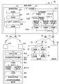
- FIG. 1 is a configuration diagram of a wireless communication system 1 according to the first embodiment.
- the wireless communication system 1 has a mobile relay station 2, a terminal station 3, and a base station 4.
- the number of each of the mobile relay station 2, the terminal station 3, and the base station 4 included in the wireless communication system 1 is arbitrary, but it is assumed that the number of the terminal stations 3 is large.
- the wireless communication system 1 is a communication system that transmits information that does not require immediacy.
- the information transmitted from each of the plurality of terminal stations 3 is transmitted via the mobile relay station 2 and collected by the base station 4.
- the mobile relay station 2 is an example of a relay device mounted on a mobile body and in which a communicable area moves with the passage of time.
- the mobile relay station 2 is provided in, for example, a LEO (Low Earth Orbit) satellite.
- the altitude of the LEO satellite is 2000 km or less, and it orbits over the earth in about 1.5 hours.
- the terminal station 3 and the base station 4 are installed on the earth such as on the ground or at sea.
- the plurality of terminal stations 3 exist in different places from each other.
- the terminal station 3 is, for example, an IoT terminal.
- the terminal station 3 collects data such as environmental data detected by the sensor and wirelessly transmits the data to the mobile relay station 2. In the figure, only two terminal stations 3 are shown.
- the mobile relay station 2 receives data transmitted from each of the plurality of terminal stations 3 by wireless signals while moving over the earth.
- the mobile relay station 2 accumulates these received data, and wirelessly transmits the accumulated data to the base station 4 at a timing when communication with the base station 4 is possible.
- the base station 4 receives the data collected by the terminal station 3 from the mobile relay station 2.
- the mobile relay station 2 it is conceivable to use a geostationary satellite or a relay station mounted on an unmanned aerial vehicle such as a drone or HAPS (High Altitude Platform Station).
- a relay station mounted on a geostationary satellite although the coverage area (footprint) on the ground is wide, the link budget for the IoT terminal installed on the ground is very small due to the high altitude.
- the link budget is high, but the coverage area is narrow.
- drones require batteries and HAPS require solar panels.
- the mobile relay station 2 is mounted on the LEO satellite. Therefore, in addition to keeping the link budget within the limit, the LEO satellite has no air resistance and consumes less fuel because it orbits outside the atmosphere.
- the footprint is large compared to the case where a relay station is mounted on a drone or HAPS.
- the mobile relay station 2 mounted on the LEO satellite communicates while moving at high speed, the time during which each terminal station 3 or base station 4 can communicate with the mobile relay station 2 is limited. Specifically, when viewed on the ground, the mobile relay station 2 passes over the sky in about 10 minutes. Further, a wireless communication method having various specifications is used for the terminal station 3. Therefore, the mobile relay station 2 receives the terminal uplink signal from the terminal station 3 within the coverage at the current position during movement, and stores the waveform data of the received terminal uplink signal. The mobile relay station 2 wirelessly transmits the base station downlink signal set with the waveform data of the terminal uplink signal to the base station 4 at the timing when the base station 4 exists in the coverage.
- the base station 4 demodulates the base station downlink signal received from the mobile relay station 2 to obtain waveform data of the terminal uplink signal.
- the base station 4 obtains terminal transmission data which is the data transmitted by the terminal station 3 by demodulating and decoding the terminal uplink signal represented by the waveform data.
- the mobile relay station 2 and the terminal station 3 perform wireless communication using LPWA (Low Power Wide Area).
- Each terminal station 3 may transmit the same terminal uplink signal to the mobile relay station 2 a plurality of times in order to ensure the reliability of communication.
- the number of terminal stations 3 is large. With such a configuration, the amount of data transmitted from the terminal station 3 to the mobile relay station 2 may increase, and the communication band may become tight.
- the wireless communication system 1 according to the present embodiment controls the transmission timing and the number of transmissions in the transmission of data from the terminal station 3 to the mobile relay station 2 in order to prevent the communication band from becoming tight.
- the mobile relay station 2 is a control signal indicating that the terminal station 3 is permitted to transmit data such as environmental data to its own mobile relay station 2 (hereinafter referred to as "transmission permission signal”). .) Is sent in advance. Further, the transmission permission signal includes information used for determining the number of times that the terminal station 3 repeatedly transmits the same terminal uplink signal to the mobile relay station 2. The information is information based on the degree of congestion of communication between a plurality of terminal stations 3 in the mobile relay station 2 (hereinafter, referred to as "congestion degree information").
- the congestion degree information is, for example, the number of terminal uplink communication accesses from a plurality of terminal stations 3 per unit time in the mobile relay station 2, or RSSI (Received Signal Strength Indicator: reception) in the frequency band of the terminal uplink communication. Information indicating signal strength).
- the terminal station 3 starts transmitting the terminal uplink signal to the mobile relay station 2 in response to receiving the transmission permission signal. Further, the terminal station 3 determines the number of times that the same terminal uplink signal is repeatedly transmitted to the mobile relay station 2 based on the congestion degree information included in the received transmission permission signal.
- transmission control process Details of the configuration and operation of each device in the process for controlling the transmission timing and the number of transmissions in the transmission of the terminal uplink signal from the terminal station 3 to the mobile relay station 2 (hereinafter referred to as “transmission control process”). Will be described later.
- transmission control process the configuration of each device in the process for the base station 4 to collect data such as environmental data transmitted from each terminal station 3 via the mobile relay station 2 (hereinafter referred to as “data collection process”). And the details of the operation will be described first.
- the mobile relay station 2 includes an antenna 21, a terminal communication unit 22, a data storage unit 23, a base station communication unit 24, and an antenna 25.
- the terminal communication unit 22 has a reception unit 221 and a reception waveform recording unit 222.
- the receiving unit 221 receives the terminal uplink signal by the antenna 21.
- the reception waveform recording unit 222 samples the reception waveform of the terminal uplink signal received by the reception unit 221 and generates waveform data showing the value obtained by the sampling.
- the reception waveform recording unit 222 writes the reception waveform information in which the reception time of the terminal uplink signal in the antenna 21 and the generated waveform data are set in the data storage unit 23.
- the data storage unit 23 stores the received waveform information written by the received waveform recording unit 222.
- the base station communication unit 24 transmits the received waveform information to the base station 4 by the base station downlink signal of any wireless communication method.
- the base station communication unit 24 includes a storage unit 241, a control unit 242, a transmission data modulation unit 243, and a transmission unit 244.
- the storage unit 241 stores the transmission start timing calculated in advance based on the orbit information of the LEO satellite equipped with the mobile relay station 2 and the position of the base station 4.
- the LEO orbit information is information that can obtain the position, speed, moving direction, etc. of the LEO satellite at an arbitrary time.
- the transmission time may be represented by, for example, the elapsed time from the transmission start timing.
- the control unit 242 controls the transmission data modulation unit 243 and the transmission unit 244 so as to transmit the received waveform information to the base station 4 at the transmission start timing stored in the storage unit 241.
- the transmission data modulation unit 243 reads the received waveform information from the data storage unit 23 as transmission data, modulates the read transmission data, and generates a base station downlink signal.
- the transmission unit 244 converts the base station downlink signal from an electric signal to a wireless signal and transmits it from the antenna 25.
- the terminal station 3 includes a data storage unit 31, a transmission unit 32, and one or more antennas 33.
- the data storage unit 31 stores sensor data and the like.
- the transmission unit 32 reads sensor data from the data storage unit 31 as terminal transmission data, and wirelessly transmits a terminal uplink signal set with the read terminal transmission data from the antenna 33.
- the transmission unit 32 transmits a signal by LPWA (Low Power Wide Area).
- LPWA includes LoRaWAN (registered trademark), Sigfox (registered trademark), LTE-M (LongTermEvolution for Machines), NB (NarrowBand) -IoT, and the like, and any wireless communication method can be used.
- the transmission unit 32 may transmit to another terminal station 3 by time division multiplexing, OFDM (Orthogonal Frequency Division Multiplexing), or the like.
- the transmission unit 32 determines the channel and transmission timing used by the station to transmit the terminal uplink signal by a method predetermined in the wireless communication method to be used.
- the transmitting unit may form a beam of signals transmitted from a plurality of antennas 33 by a method predetermined in the wireless communication method to be used.
- the base station 4 includes an antenna 41, a receiving unit 42, a base station signal receiving processing unit 43, and a terminal signal receiving processing unit 44.
- the receiving unit 42 converts the base station downlink signal received by the antenna 41 into an electric signal.
- the base station signal reception processing unit 43 demodulates and decodes the received signal converted into an electric signal by the receiving unit 42, and obtains received waveform information.
- the base station signal reception processing unit 43 outputs the received waveform information to the terminal signal reception processing unit 44.
- the terminal signal reception processing unit 44 performs reception processing of the terminal uplink signal indicated by the received waveform information. At this time, the terminal signal reception processing unit 44 performs reception processing by the wireless communication method used for transmission by the terminal station 3 to acquire terminal transmission data.
- the terminal signal reception processing unit 44 includes a terminal signal demodulation unit 441 and a terminal signal decoding unit 442.
- the terminal signal demodulation unit 441 demodulates the waveform data and outputs the symbol obtained by the demodulation to the terminal signal decoding unit 442.
- the terminal signal demodulation unit 441 may perform demodulation after performing a process of compensating for the Doppler shift of the terminal uplink signal received by the antenna 21 of the mobile relay station 2 with respect to the signal indicated by the waveform data.
- the Doppler shift received by the terminal uplink signal received by the antenna 21 is calculated in advance based on the position of the terminal station 3 and the orbit information of the LEO on which the mobile relay station 2 is mounted.
- the terminal signal decoding unit 442 decodes the symbol demodulated by the terminal signal demodulation unit 441 and obtains the terminal transmission data transmitted from the terminal station 3.
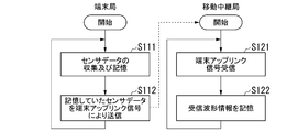
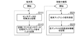
- FIG. 2 is a flow chart showing the processing of the wireless communication system 1 when the terminal uplink signal is transmitted from the terminal station 3.
- the terminal station 3 acquires data detected by a sensor (not shown) provided externally or internally at any time, and writes the acquired data in the data storage unit 31 (step S111).
- the transmission unit 32 reads the sensor data from the data storage unit 31 as terminal transmission data.
- the transmission unit 32 wirelessly transmits the terminal uplink signal set with the terminal transmission data from the antenna 33 at the transmission start timing obtained in advance based on the orbit information of the LEO satellite equipped with the mobile relay station 2 (step S112). ..
- the terminal station 3 repeats the process from step S111.
- the receiving unit 221 of the mobile relay station 2 receives the terminal uplink signal transmitted from the terminal station 3 (step S121). Depending on the wireless communication method of the source terminal station 3, there are cases where the terminal uplink signal is received from only one terminal station 3 in a time division for the same frequency, and cases where the terminal uplink signal is received from multiple terminal stations 3 at the same frequency at the same frequency. It may receive a terminal uplink signal.
- the reception waveform recording unit 222 writes the received waveform information in which the waveform data representing the waveform of the terminal uplink signal received by the receiving unit 221 and the reception time are associated with each other in the data storage unit 23 (step S122). The mobile relay station 2 repeats the process from step S121.
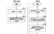
- FIG. 3 is a flow chart showing the processing of the wireless communication system 1 when the base station downlink signal is transmitted from the mobile relay station 2.
- the control unit 242 of the base station communication unit 24 of the mobile relay station 2 detects that the transmission start timing is stored in the storage unit 241, the transmission of the received waveform information is transmitted to the transmission data modulation unit 243 and the transmission unit 244.
- Instruct step S211).
- the transmission data modulation unit 243 reads the received waveform information stored in the data storage unit 23 as transmission data, modulates the read transmission data, and generates a base station downlink signal.
- the transmission unit 244 wirelessly transmits the base station downlink signal generated by the transmission data modulation unit 243 from the antenna 25 (step S212).
- the mobile relay station 2 repeats the process from step S211.
- the antenna 41 of the base station 4 receives the base station downlink signal from the mobile relay station 2 (step S221).
- the receiving unit 42 converts the base station downlink signal received by the antenna 41 into a received signal of an electric signal, and outputs the signal to the base station signal receiving processing unit 43.
- the base station signal reception processing unit 43 demodulates the received signal and decodes the demodulated received signal (step S222).
- the base station signal reception processing unit 43 outputs the reception waveform information obtained by decoding to the terminal signal reception processing unit 44.
- the terminal signal reception processing unit 44 performs reception processing of the terminal uplink signal represented by the waveform data included in the received waveform information (step S223). Specifically, the terminal signal demodulation unit 441 specifies the wireless communication method used by the terminal station 3 to transmit the terminal uplink signal based on the information unique to the wireless communication method included in the received signal represented by the waveform data. .. The terminal signal demodulation unit 441 demodulates the received signal represented by the waveform data according to the specified wireless communication method, and outputs the symbol obtained by the demodulation to the terminal signal decoding unit 442. The terminal signal decoding unit 442 decodes the symbol input from the terminal signal demodulation unit 441 by the specified wireless communication method, and obtains the terminal transmission data transmitted from the terminal station 3. The terminal signal decoding unit 442 can also use a decoding method having a large calculation load, such as SIC (Successive Interference Cancellation).
- the base station 4 repeats the process from step S221.
- the mobile relay station 2 further includes a communication status measurement unit 223, a timing control unit 224, a storage unit 225, and a transmission unit 226.
- the communication status measurement unit 223 measures the communication status of the terminal uplink communication from the plurality of terminal stations 3 in the reception unit 221. For example, the communication status measuring unit 223 measures the number of access of the terminal uplink communication from the plurality of terminal stations 3 per unit time in the receiving unit 221 or the reception signal strength of the frequency band of the terminal uplink communication.
- the communication status referred to here is arbitrary information that quantitatively represents the degree of congestion of communication.
- the communication status measurement unit 223 generates congestion degree information based on the measured information.
- the congestion degree information is information used for determining the number of times that the terminal station 3 repeatedly transmits the same terminal uplink signal to the mobile relay station 2.
- the congestion degree information may be the information itself indicating the number of access of the terminal uplink communication from the plurality of terminal stations 3 per unit time, or the received signal strength of the frequency band of the terminal uplink communication.
- the information indicating the number of access of the terminal uplink communication from the plurality of terminal stations 3 per unit time or the received signal strength of the frequency band of the terminal uplink communication is within a predetermined threshold range. It may be information indicating a level determined based on whether or not. That is, for example, the number of access of the terminal uplink communication per unit time from a plurality of terminal stations 3 is level 1 when it is within a certain range, level 2 when it is within a larger range, and even more range. If it is within, the level is uniquely determined, such as level 3. In this case, the information in which the range and the level of the access number and the received signal strength value are associated with each other is stored in advance in, for example, the storage unit 225.
- the congestion degree information may be the value of the number of times that the terminal station 3 repeatedly transmits the same terminal uplink signal to the mobile relay station 2. That is, for example, 5 times when the received signal strength of the frequency band of the terminal uplink communication from the plurality of terminal stations 3 is within a certain range, 4 times when the strength is within a lower range, and more.
- the intensity is within the low range, the value of the number of transmissions is uniquely determined, such as level 3 times.
- the information in which the range of the values of the number of accesses and the received signal strength and the number of transmissions are associated with each other is stored in advance in, for example, a storage unit 225.
- the timing control unit 224 controls the timing of transmitting the terminal downlink signal for which the transmission permission signal is set to the terminal station 3.
- the transmission permission signal is a control signal indicating that the terminal station 3 is permitted to transmit data such as environmental data to its own mobile relay station 2.
- the timing control unit 224 acquires the congestion degree information generated by the communication status measurement unit 223.
- the timing control unit 224 generates a transmission permission signal including the acquired congestion degree information.
- the transmission unit 226 acquires the transmission permission signal generated by the timing control unit 224, and wirelessly transmits the terminal downlink signal in which the acquired transmission permission signal is set from the antenna 21.
- the transmission unit 226 transmits a signal by LPWA. Any wireless communication method such as LoRaWAN (registered trademark), Sigfox (registered trademark), LTE-M, NB-IoT, etc. can be used for LPWA.
- the transmission unit 226 determines the channel used by the station for transmitting the terminal downlink signal by a method predetermined in the wireless communication method to be used.
- the timing at which the transmission unit 226 transmits the terminal downlink signal is controlled by the timing control unit 224.
- the storage unit 225 stores the transmission start timing for each terminal station 3 calculated in advance based on the orbit information of the LEO satellite equipped with the mobile relay station 2 and the position of each terminal station 3.
- the LEO orbit information is information that can obtain the position, speed, moving direction, etc. of the LEO satellite at an arbitrary time.
- the transmission time may be represented by, for example, the elapsed time from the transmission start timing.
- the timing control unit 224 controls the transmission unit 226 so as to transmit the terminal downlink signal in which the transmission permission signal is set to each terminal station 3 at the transmission start timing for each terminal station 3 stored in the storage unit 225. ..
- the timing control unit 224 includes, for example, the congestion degree information generated when the terminal uplink signal is received from the same terminal station 3 before (for example, at the time before one round) in the transmission permission signal.
- the timing control unit 224 may include, for example, the congestion degree information generated when the terminal uplink signal is received from the same terminal station 3 in the same time zone in the past in the transmission permission signal.
- the timing control unit 224 may include the congestion degree information generated immediately before the timing of transmitting the transmission permission signal to the terminal station 3 (for example, one minute before) in the transmission permission signal.
- the storage unit 225 stores in advance the terminal identification information for identifying the terminal station 3 and the position information indicating the position of the terminal station 3.
- the timing control unit 224 determines the terminal station 3 to be notified based on the current position of the own station and the position of the terminal station 3, and identifies the terminal identification information of the specified terminal station 3.
- the timing control unit 224 includes the identified terminal identification information in the transmission permission signal.
- the terminal station 3 further includes a receiving unit 34 and a transmission control unit 35.
- the receiving unit 34 receives the terminal downlink signal by the antenna 33.
- the transmission control unit 35 acquires a transmission permission signal from the terminal downlink signal received by the reception unit 34.
- the transmission control unit 35 acquires the terminal identification information included in the acquired transmission permission signal.
- the transmission control unit 35 acquires the congestion degree information included in the acquired transmission permission signal. If the acquired terminal identification information is not the identification information associated with the own station, the terminal station 3 stands by without starting transmission of data to the mobile relay station 2.
- the transmission control unit 35 determines the number of times that the same terminal uplink signal is repeatedly transmitted to the mobile relay station 2 based on the acquired congestion degree information.
- the transmission control unit 35 is congestion degree information indicating the number of access to the terminal uplink communication from the plurality of terminal stations 3 per unit time in the reception unit 221 or the reception signal strength of the frequency band of the terminal uplink communication. To get.
- the information in which the range of the values of the number of accesses and the received signal strength and the number of transmissions are associated with each other is stored in advance in, for example, a storage medium included in the terminal station 3.
- the transmission control unit 35 determines the number of transmissions based on the number of accesses and the reception signal strength indicated by the congestion degree information.
- the transmission control unit 35 acquires the congestion degree information indicating the congestion degree level (the above-mentioned level 1, level 2, etc.) in the reception unit 221.
- the information in which the congestion level and the number of transmissions are associated is stored in advance in, for example, a storage medium included in the terminal station 3.
- the transmission control unit 35 determines the number of transmissions based on the level of congestion indicated by the congestion degree information.
- the transmission control unit 35 acquires congestion degree information indicating the number of transmissions determined by the mobile relay station 2. In this case, the transmission control unit 35 determines the number of transmissions indicated by the congestion degree information.
- the transmission unit 32 starts transmitting the terminal uplink signal.
- the transmission unit 32 reads sensor data from the data storage unit 31 as terminal transmission data, and wirelessly transmits a terminal uplink signal set with the read terminal transmission data from the antenna 33.
- the transmission unit 32 transmits a signal by LPWA. Further, the transmission unit 32 repeatedly transmits the same terminal uplink signal as many times as the number of transmissions determined by the transmission control unit 35.
- the receiving unit 221 of the mobile relay station 2 receives the terminal uplink signal by the antenna 21.
- the reception waveform recording unit 222 samples the reception waveform of the terminal uplink signal received by the reception unit 221 and generates waveform data showing the value obtained by the sampling. Since the terminal station 3 transmits one sensor data a plurality of times, a plurality of waveform data corresponding to the same terminal uplink signal are generated.
- the received waveform recording unit 222 selects, for example, the waveform data having the best reception state from a plurality of waveform data corresponding to the same terminal uplink signal.
- the reception waveform recording unit 222 writes the reception waveform information in which the reception time of the terminal uplink signal in the antenna 21 and the selected waveform data are set in the data storage unit 23.
- the data storage unit 23 stores the received waveform information written by the received waveform recording unit 222.
- the received waveform recording unit 222 writes, for example, the received waveform information in which the waveform data generated by averaging a plurality of waveform data corresponding to the same terminal uplink signal is set in the data storage unit 23. You may.
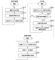
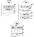
- FIG. 4 is a flow chart showing processing of the wireless communication system 1 when a terminal downlink signal is transmitted from the mobile relay station 2 to the terminal station 3.
- the communication status measuring unit 223 of the mobile relay station 2 measures the communication status of the terminal uplink communication from the plurality of terminal stations 3 in the receiving unit 221 (step S311).
- the communication status is, for example, the number of access of the terminal uplink communication per unit time, the received signal strength of the frequency band of the terminal uplink communication, and the like.
- the communication status measurement unit 223 generates congestion degree information used for determining the number of times the terminal station 3 repeatedly transmits the same terminal uplink signal to the mobile relay station 2 based on the measured communication status ().
- Step S312 The timing control unit 224 generates transmission permission information including the generated congestion degree information and the terminal identification information of the terminal station 3 to be notified.
- the transmission unit 226 acquires the transmission permission signal generated by the timing control unit 224.
- the transmission unit 226 wirelessly transmits the terminal downlink signal in which the acquired transmission permission signal is set, for example, from the antenna 21 at the next lap (step S313).
- the mobile relay station 2 repeats the process from step S311.
- the receiving unit 34 of the terminal station 3 receives the terminal downlink signal transmitted from the mobile relay station 2 by the antenna 33 (step S321).
- the transmission control unit 35 acquires the terminal identification information included in the transmission permission signal indicated by the terminal downlink signal received by the reception unit 34.
- the transmission control unit 35 moves based on the congestion degree information included in the acquired transmission permission signal.
- the number of times that the same terminal uplink signal is repeatedly transmitted to the relay station 2 is determined (step S323).
- the transmission control unit 35 repeats the process from step S321.
- the transmission unit 32 reads sensor data from the data storage unit 31 as terminal transmission data, and wirelessly transmits a terminal uplink signal set with the read terminal transmission data from the antenna 33.
- the transmission unit 32 transmits the same terminal uplink signal a plurality of times as many times as the number of transmissions determined by the transmission control unit 35 (step S323).
- the terminal station 3 repeats the process from step S321.
- the receiving unit 221 of the mobile relay station 2 receives the terminal uplink signal transmitted from the terminal station 3 a plurality of times by the antenna 21 (step S331).
- the reception waveform recording unit 222 samples the reception waveforms of the plurality of terminal uplink signals received by the reception unit 221, and generates waveform data indicating the values obtained by the sampling.
- the received waveform recording unit 222 selects, for example, the waveform data having the best reception state from the plurality of waveform data corresponding to the same terminal uplink signal (step S332).
- the reception waveform recording unit 222 stores the reception waveform information in which the reception time of the terminal uplink signal in the antenna 21 and the selected waveform data are set in the data storage unit 23 (step S333).
- the mobile relay station 2 repeats the process from step S331.
- the mobile relay station 2 receives the terminal uplink signals transmitted from each of the plurality of terminal stations 3 and measures the communication status.
- the mobile relay station 2 generates congestion degree information based on the communication status.
- the mobile relay station 2 sets a transmission permission signal including congestion degree information as a terminal downlink signal and transmits the transmission to the terminal station 3.
- the terminal station 3 starts transmitting the terminal uplink signal to the mobile relay station 2 by acquiring the transmission permission signal indicated by the received terminal downlink signal.
- the wireless communication system 1 can control the transmission timing of the terminal uplink signal from the terminal station 3 to the mobile relay station 2.
- the terminal station 3 determines the number of transmissions of repeatedly transmitting the terminal uplink signal based on the congestion degree information included in the transmission permission signal.
- the wireless communication system 1 can be controlled so that the higher the degree of communication congestion in the mobile relay station 2, the smaller the number of times the terminal uplink signal is transmitted from the terminal station 3. Therefore, the wireless communication system 1 transmits sensor data transmitted from more terminal stations 3 to the mobile relay station 2 while suppressing a decrease in communication reliability even when the degree of communication congestion fluctuates. It can be transmitted to the base station 4 via.
- the congestion degree information transmitted from the mobile relay station 2 to the terminal station 3 is information indicating the communication congestion degree itself, such as the number of access times of the terminal uplink signal per unit time and the received signal strength. It may be information indicating the number of transmissions determined based on the degree of congestion.
- the terminal station 3 determines the number of transmissions based on the congestion degree information.
- the device configuration of the mobile relay station 2 can be simplified. Further, in this case, it is also possible to configure each terminal station 3 to determine the number of transmissions from the congestion degree information based on different determination criteria. Therefore, it becomes possible to flexibly design the system.
- the mobile relay station 2 determines the number of transmissions based on the congestion degree information.
- the function of determining the number of transmissions from the congestion degree information can be integrated in the mobile relay station 2.
- miniaturization and power saving of the device are generally required, but in this case, the device configuration of the terminal station 3 can be simplified.
- the mobile relay station transmits a base station downlink signal by a plurality of antennas.
- MIMO Multiple Input Multiple Output
- FIG. 5 is a configuration diagram of a wireless communication system 1a according to a modification 1 of the first embodiment.
- the wireless communication system 1a has a mobile relay station 2a, a terminal station 3, and a base station 4a.
- the mobile relay station 2a includes an antenna 21, a terminal communication unit 22, a data storage unit 23, a base station communication unit 26, and a plurality of antennas 25.
- the base station communication unit 26 transmits received waveform information to the base station 4a by MIMO.
- the base station communication unit 26 includes a storage unit 261, a control unit 262, a transmission data modulation unit 263, and a MIMO transmission unit 264.
- the storage unit 261 stores the transmission start timing calculated in advance based on the orbit information of the LEO satellite equipped with the mobile relay station 2a and the position of the base station 4a. Further, the storage unit 261 stores in advance the wait for each transmission time of the base station downlink signal transmitted from each antenna 25.
- the weight for each transmission time is calculated based on the orbit information of the LEO satellite and the position of each antenna station 410 included in the base station 4a. A constant weight may be used regardless of the transmission time.
- the control unit 262 controls the transmission data modulation unit 263 and the MIMO transmission unit 264 so as to transmit the received waveform information to the base station 4a at the transmission start timing stored in the storage unit 261. Further, the control unit 262 instructs the MIMO transmission unit 264 to wait for each transmission time read from the storage unit 261.
- the transmission data modulation unit 263 reads the received waveform information from the data storage unit 23 as transmission data, converts the read transmission data into a parallel signal, and then modulates it.
- the MIMO transmission unit 264 weights the modulated parallel signal by the weight instructed by the control unit 262, and generates a base station downlink signal transmitted from each antenna 25.
- the MIMO transmission unit 264 transmits the generated base station downlink signal from the antenna 25 by MIMO.
- the base station 4a includes a plurality of antenna stations 410, a MIMO receiving unit 420, a base station signal receiving processing unit 430, and a terminal signal receiving processing unit 44.
- the antenna station 410 is arranged at a position away from the other antenna stations 410 so that the difference in the arrival angles of the signals from each of the plurality of antennas 25 of the mobile relay station 2a is large.
- Each antenna station 410 converts the base station downlink signal received from the mobile relay station 2a into an electric signal and outputs it to the MIMO receiving unit 420.
- the MIMO receiver 420 aggregates the base station downlink signals received from the plurality of antenna stations 410.
- the MIMO receiving unit 420 stores the weight for each reception time for the base station downlink signal received by each antenna station 410 based on the orbit information of the LEO satellite and the position of each antenna station 410.
- the MIMO receiving unit 420 multiplies the base station downlink signal input from each antenna station 410 by the weight corresponding to the reception time of the base station downlink signal, and synthesizes the received signal to which the weight is multiplied. The same weight may be used regardless of the reception time.
- the base station signal reception processing unit 430 demodulates and decodes the synthesized received signal to obtain received waveform information.
- the base station signal reception processing unit 430 outputs the received waveform information to the terminal signal reception processing unit 44.
- the processing of the wireless communication system 1a when transmitting the terminal uplink signal from the terminal station 3 is the same as the processing of the wireless communication system 1 of the first embodiment shown in FIG.
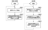
- FIG. 6 is a flow chart showing the processing of the wireless communication system 1a when the base station downlink signal is transmitted from the mobile relay station 2a.
- the control unit 262 of the base station communication unit 26 of the mobile relay station 2a detects that it is the transmission start timing stored in the storage unit 261, it transmits the received waveform information to the transmission data modulation unit 263 and the MIMO transmission unit 264. (Step S411).
- the transmission data modulation unit 263 reads the received waveform information stored in the data storage unit 23 as transmission data, performs parallel conversion of the read transmission data, and then modulates the read transmission data.
- the MIMO transmission unit 264 weights the transmission data modulated by the transmission data modulation unit 263 by the weight instructed by the control unit 262 to generate a base station downlink signal which is a transmission signal transmitted from each antenna 25.
- the MIMO transmission unit 264 transmits each generated base station downlink signal from the antenna 25 by MIMO (step S412).
- the mobile relay station 2a repeats the process from step S411.
- Each antenna station 410 of the base station 4a receives a base station downlink signal from the mobile relay station 2a (step S421).
- Each antenna station 410 outputs a received signal obtained by converting the received base station downlink signal into an electric signal to the MIMO receiving unit 420.
- the MIMO receiving unit 420 synchronizes the timing of the received signal received from each antenna station 410.
- the MIMO receiving unit 420 multiplies and adds the received signal received by each antenna station 410 by a weight.
- the base station signal reception processing unit 430 demodulates the added received signal and decodes the demodulated received signal (step S422).
- the base station signal reception processing unit 430 outputs the reception waveform information obtained by decoding to the terminal signal reception processing unit 44.
- the terminal signal reception processing unit 44 performs reception processing of the terminal uplink signal represented by the waveform data included in the received waveform information by the same processing as in step S223 in the processing flow of the first embodiment shown in FIG. 3 (step). S423). That is, the terminal signal demodulation unit 441 specifies the wireless communication method used by the terminal station 3 to transmit the terminal uplink signal based on the information unique to the wireless communication method included in the received signal represented by the waveform data. The terminal signal demodulation unit 441 demodulates the received signal represented by the waveform data according to the specified wireless communication method, and outputs the symbol obtained by the demodulation to the terminal signal decoding unit 442.
- the terminal signal decoding unit 442 decodes the symbol input from the terminal signal demodulation unit 441 by the specified wireless communication method, and obtains the terminal transmission data transmitted from the terminal station 3.
- the terminal signal decoding unit 442 can also use a decoding method having a large calculation load, such as SIC.
- the base station 4a repeats the process from step S421.
- the mobile relay station 2a collectively collects the stored data received from the plurality of terminal stations 3 at a timing capable of communicating with the base station 4a in a short time. Can be sent with good quality.
- the mobile relay station receives the terminal uplink signal from a plurality of antennas and transmits the terminal downlink signal from the plurality of antennas.
- the difference from the first modification of the first embodiment will be mainly described.
- FIG. 7 is a configuration diagram of a wireless communication system 1b according to a modification 2 of the first embodiment.
- the wireless communication system 1b has a mobile relay station 2b, a terminal station 3, and a base station 4b.
- the mobile relay station 2b includes N antennas 21 (N is an integer of 2 or more), a terminal communication unit 22b, a data storage unit 23, a base station communication unit 26, and a plurality of antennas 25.
- the N antennas 21 are described as antennas 21-1 to 21-N, respectively.
- the terminal communication unit 22b has N reception units 221b and N reception waveform recording units 222b.
- the N receiving units 221b are referred to as receiving units 221b-1 to 221b-N, and the N receiving waveform recording units 222b are referred to as receiving waveform recording units 222b-1 to 222b-N.
- the receiving unit 221b-n (n is an integer of 1 or more and N or less) receives the terminal uplink signal by the antenna 21-n.
- the reception waveform recording unit 222bn samples the reception waveform of the terminal uplink signal received by the reception unit 221bn, and generates waveform data showing the value obtained by the sampling.
- the received waveform recording unit 222b-n writes the received waveform information in which the antenna identifier of the antenna 21-n, the reception time of the terminal uplink signal in the antenna 21-n, and the generated waveform data are set to the data storage unit 23. ..
- the antenna identifier is information that identifies the antenna 21-n.
- the data storage unit 23 stores received waveform information including waveform data of the terminal uplink signal received by each of the antennas 21-1 to 21-N.
- the base station 4b includes a plurality of antenna stations 410, a MIMO receiving unit 420, a base station signal receiving processing unit 430, and a terminal signal receiving processing unit 450.
- the terminal signal reception processing unit 450 performs reception processing of the terminal uplink signal indicated by the received waveform information. At this time, the terminal signal reception processing unit 450 performs reception processing by the wireless communication method used for transmission by the terminal station 3 to acquire terminal transmission data.
- the terminal signal reception processing unit 450 includes a distribution unit 451, N terminal signal demodulation units 452, a synthesis unit 453, and a terminal signal decoding unit 454.
- the N terminal signal demodulation units 452 are described as terminal signal demodulation units 452-1 to 452-N, respectively.
- the distribution unit 451 reads out waveform data at the same reception time from the received waveform information, and outputs the read waveform data to the terminal signal demodulation units 452-1 to 452-N according to the antenna identifier associated with the waveform data. do. That is, the distribution unit 451 outputs the waveform data associated with the antenna identifier of the antenna 21-n to the terminal signal demodulation unit 452-n.
- Each of the terminal signal demodulation units 452-1 to 452-N demodulates the signal represented by the waveform data, and outputs the symbol obtained by the demodulation to the synthesis unit 453.
- the terminal signal demodulation unit 452-n performs a process of compensating for the Doppler shift of the terminal uplink signal received by the antenna 21-n of the mobile relay station 2 with respect to the signal represented by the waveform data, and then demodulates the signal. May be good.
- the Doppler shift received by the terminal uplink signal received by each antenna 21-n is calculated in advance based on the position of the terminal station 3 and the orbit information of the LEO on which the mobile relay station 2b is mounted.
- the synthesis unit 453 adds and synthesizes the symbols input from each of the terminal signal demodulation units 452-1 to 452-N, and outputs them to the terminal signal decoding unit 454.
- the terminal signal decoding unit 454 decodes the additively synthesized symbol and obtains the terminal transmission data transmitted from the terminal station 3.
- the mobile relay station 2 further includes a communication status measurement unit 223b, a timing control unit 224b, a storage unit 225, and a transmission unit 226b.
- the communication status measuring unit 223b measures the communication status of the terminal uplink communication from the plurality of terminal stations 3 in the receiving units 221b-1 to 221b-N.
- the communication status measuring unit 223b is the number of access of the terminal uplink communication from a plurality of terminal stations 3 per unit time in the receiving units 221b-1 to 221b-N, or the reception signal of the frequency band of the terminal uplink communication. Measure the strength.
- the communication status measurement unit 223b generates congestion degree information based on the measured information.
- the congestion degree information may be the information itself indicating the number of access of the terminal uplink communication from the plurality of terminal stations 3 per unit time or the received signal strength of the frequency band of the terminal uplink communication.
- the information indicating the number of access of the terminal uplink communication from the plurality of terminal stations 3 per unit time or the received signal strength of the frequency band of the terminal uplink communication is within a predetermined threshold range. It may be information indicating a level determined based on whether or not.
- the congestion degree information may be the value itself of the number of times that the terminal station 3 repeatedly transmits the same terminal uplink signal to the mobile relay station 2b.
- the timing control unit 224b controls the timing of transmitting the terminal downlink signal in which the transmission permission signal is set to the terminal station 3.
- the timing control unit 224b acquires the congestion degree information generated by the communication status measurement unit 223b.
- the timing control unit 224b generates a transmission permission signal including the acquired congestion degree information.
- the transmission unit 226b acquires the transmission permission signal generated by the timing control unit 224b, and wirelessly transmits the terminal downlink signal in which the acquired transmission permission signal is set from the plurality of antennas 21.
- the transmission unit 226b transmits a signal by LPWA.
- the transmission unit 226b determines the channel used by the station for transmitting the terminal downlink signal by a predetermined method in the wireless communication method to be used.
- the timing at which the transmission unit 226b transmits the terminal downlink signal is controlled by the timing control unit 224b.
- the storage unit 225 stores the transmission start timing for each terminal station 3 calculated in advance based on the orbit information of the LEO satellite equipped with the mobile relay station 2b and the position of each terminal station 3.
- the timing control unit 224b controls the transmission unit 226b so as to transmit the terminal downlink signal in which the transmission permission signal is set to each terminal station 3 at the transmission start timing for each terminal station 3 stored in the storage unit 225. ..
- the timing control unit 224b includes, for example, the congestion degree information generated when the terminal uplink signal is received from the same terminal station 3 at the time before one round in the transmission permission signal.
- the timing control unit 224b may include, for example, the congestion degree information generated when the terminal uplink signal is received from the same terminal station 3 in the same time zone in the past in the transmission permission signal.
- the timing control unit 224b may include the congestion degree information generated immediately before (for example, one minute before) the timing of transmitting the transmission permission signal to the terminal station 3 in the transmission permission signal.
- the storage unit 225 stores in advance the terminal identification information for identifying the terminal station 3 and the position information indicating the position of the terminal station 3.
- the timing control unit 224b identifies the terminal identification information of the terminal station 3 to be notified based on the current position of the own station and the position of the terminal station 3.
- the timing control unit 224b includes the identified terminal identification information in the transmission permission signal.
- the terminal station 3 further includes a receiving unit 34 and a transmission control unit 35.
- the receiving unit 34 receives the terminal downlink signal by the antenna 33.
- the transmission control unit 35 acquires a transmission permission signal from the terminal downlink signal received by the reception unit 34.
- the transmission control unit 35 acquires the terminal identification information included in the acquired transmission permission signal.
- the transmission control unit 35 acquires the congestion degree information included in the acquired transmission permission signal. If the acquired terminal identification information is not the identification information associated with the own station, the terminal station 3 stands by without starting transmission of data to the mobile relay station 2.
- the transmission control unit 35 determines the number of times that the same terminal uplink signal is repeatedly transmitted to the mobile relay station 2 based on the acquired congestion degree information. For example, the transmission control unit 35 provides congestion degree information indicating the number of access to the terminal uplink communication from the plurality of terminal stations 3 per unit time in the reception unit 221 or the reception signal strength of the frequency band of the terminal uplink communication. get. In this case, the information in which the range of the values of the number of accesses and the received signal strength and the number of transmissions are associated with each other is stored in advance in, for example, a storage medium included in the terminal station 3. The transmission control unit 35 determines the number of transmissions based on the number of accesses and the reception signal strength indicated by the congestion degree information.
- the transmission control unit 35 acquires the congestion degree information indicating the congestion degree level (the above-mentioned level 1, level 2, etc.) in the reception unit 221.
- the information in which the congestion level and the number of transmissions are associated is stored in advance in, for example, a storage medium included in the terminal station 3.
- the transmission control unit 35 determines the number of transmissions based on the level of congestion indicated by the congestion degree information.
- the transmission control unit 35 acquires congestion degree information indicating the number of transmissions determined by the mobile relay station 2. In this case, the transmission control unit 35 determines the number of transmissions indicated by the congestion degree information.
- the transmission unit 32 starts transmitting the terminal uplink signal.
- the transmission unit 32 reads sensor data from the data storage unit 31 as terminal transmission data, and wirelessly transmits a terminal uplink signal set with the read terminal transmission data from the antenna 33.
- the transmission unit 32 transmits a signal by LPWA. Further, the transmission unit 32 repeatedly transmits the same terminal uplink signal as many times as the number of transmissions determined by the transmission control unit 35.
- the receiving units 221b-1 to 221b-N receive the terminal uplink signal by the plurality of antennas 21.
- the reception waveform recording unit 222 samples the reception waveform of the terminal uplink signal received by the reception units 221b-1 to 221b-N, and generates waveform data showing the value obtained by the sampling. Since the terminal station 3 transmits one sensor data a plurality of times, a plurality of waveform data corresponding to the same terminal uplink signal are generated.
- the received waveform recording units 222b-1 to 222b-N select, for example, the waveform data having the best reception state from a plurality of waveform data corresponding to the same terminal uplink signal.
- the received waveform recording units 222b-1 to 222b-N write the received waveform information in which the reception time of the terminal uplink signal in the antenna 21 and the selected waveform data are set in the data storage unit 23.
- the data storage unit 23 stores the received waveform information written by the received waveform recording units 222b-1 to 222b-N.
- the received waveform recording units 222b-1 to 222b-N store, for example, received waveform information in which waveform data generated by averaging a plurality of waveform data corresponding to the same terminal uplink signal is set. You may write in the part 23.
- FIG. 8 is a flow chart showing the processing of the wireless communication system 1b when the terminal uplink signal is transmitted from the terminal station 3.
- the terminal station 3 performs the same processing as the processing of steps S111 to S112 in the processing flow of the first embodiment shown in FIG.
- the terminal station 3 may transmit to another terminal station 3 by time division multiplexing, OFDM, MIMO, or the like.
- the receiving units 221b-1 to 221b-N of the mobile relay station 2b receive the terminal uplink signal transmitted from the terminal station 3 (step S521).
- the terminal uplink signal is received from only one terminal station 3 in a time division for the same frequency, and cases where the terminal uplink signal is received from multiple terminal stations 3 at the same frequency at the same frequency. It may receive a terminal uplink signal.
- the received waveform recording unit 222bn data is waveform data representing the waveform of the terminal uplink signal received by the receiving unit 221bn, and received waveform information in which the reception time and the antenna identifier of the antenna 21-n are associated with each other.
- the mobile relay station 2b repeats the process from step S521.
- the processing of the wireless communication system 1b when transmitting the base station downlink signal from the mobile relay station 2b is the same as the processing flow of the first embodiment shown in FIG. 6 except for the following processing. .. That is, in step S423, the terminal signal reception processing unit 450 performs reception processing of the terminal uplink signal indicated by the received waveform information. Specifically, the distribution unit 451 reads out waveform data having the same reception time from the received waveform information, and reads the read waveform data according to the antenna identifier associated with the waveform data, from the terminal signal demodulation unit 452-1 to Output to 452-N.
- the terminal signal demodulation units 452-1 to 452-N each use the wireless communication method used by the terminal station 3 to transmit the terminal uplink signal based on the information unique to the wireless communication method included in the received signal represented by the waveform data. Identify.
- the terminal signal demodulation units 452-1 to 452-N demodulate the received signal represented by the waveform data according to the specified wireless communication method, and output the symbol obtained by the demodulation to the synthesis unit 453.
- the synthesis unit 453 adds and synthesizes the symbols input from each of the terminal signal demodulation units 452-1 to 452-N.
- the signal transmitted by the terminal station 3 is emphasized because it has a correlation, but the influence of randomly added noise is reduced. Therefore, the diversity effect can be obtained for the terminal uplink signal received by the mobile relay station 2b from only one terminal station 3 at the same time. Further, the terminal uplink signal received by the mobile relay station 2b from a plurality of terminal stations 3 at the same time corresponds to performing MIMO communication.
- the synthesis unit 453 outputs the additively synthesized symbol to the terminal signal decoding unit 454.
- the terminal signal decoding unit 454 decodes the symbol added and synthesized by the synthesis unit 453 by the specified wireless communication method, and obtains the terminal transmission data transmitted from the terminal station 3.
- the terminal signal decoding unit 454 can also use a decoding method having a large calculation load, such as SIC.
- FIG. 9 is a flow chart showing the processing of the wireless communication system 1b when the terminal downlink signal is transmitted from the mobile relay station 2b.
- the communication status measuring unit 223b of the mobile relay station 2b measures the communication status of the terminal uplink communication from the plurality of terminal stations 3 in the receiving units 221b-1 to 221b-N (step S611).
- the communication status measurement unit 223b generates congestion degree information used for determining the number of times the terminal station 3 repeatedly transmits the same terminal uplink signal to the mobile relay station 2b based on the measured information (step). S612).
- the timing control unit 224b generates transmission permission information including the generated congestion degree information and the terminal identification information of the terminal station 3 to be notified.
- the transmission unit 226b acquires the transmission permission signal generated by the timing control unit 224b.
- the transmission unit 226b wirelessly transmits the terminal downlink signal in which the acquired transmission permission signal is set from the plurality of antennas 21, for example, at the next lap (step S613).
- the mobile relay station 2b repeats the process from step S611.
- the receiving unit 34 of the terminal station 3 receives the terminal downlink signal transmitted from the mobile relay station 2b by the antenna 33 (step S621).
- the transmission control unit 35 acquires the terminal identification information included in the transmission permission signal indicated by the terminal downlink signal received by the reception unit 34.
- the transmission control unit 35 moves based on the congestion degree information included in the acquired transmission permission signal.
- the number of times that the same terminal uplink signal is repeatedly transmitted to the relay station 2b is determined (step S623).
- the transmission control unit 35 repeats the process from step S621.
- the transmission unit 32 reads sensor data from the data storage unit 31 as terminal transmission data, and wirelessly transmits a terminal uplink signal set with the read terminal transmission data from the antenna 33.
- the transmission unit 32 transmits the same terminal uplink signal a plurality of times as many times as the number of transmissions determined by the transmission control unit 35 (step S623).
- the terminal station 3 repeats the process from step S621.
- the receiving units 221b-1 to 221b-N of the mobile relay station 2b receive the terminal uplink signal transmitted from the terminal station 3 a plurality of times by the plurality of antennas 21 (step S631).
- the received waveform recording units 222b-1 to 222b-N sample the received waveforms of the plurality of terminal uplink signals received by the receiving units 221b-1 to 221b-N, and obtain waveform data showing the values obtained by sampling. Generate each.
- the received waveform recording units 222b-1 to 222b-N select, for example, the waveform data having the best reception state from the plurality of waveform data corresponding to the same terminal uplink signal (step S632).
- the received waveform recording units 222b-1 to 222b-N store the received waveform information in which the reception time of the terminal uplink signal in each antenna 21 and the selected waveform data are set in the data storage unit 23 (step S633). ).
- the mobile relay station 2b repeats the process from step S631.
- the mobile relay station 2b receives the terminal uplink signal transmitted from the terminal station 3 by diversity reception, MIMO reception, or the like. Therefore, according to the wireless communication system 1b according to the present modification, it is possible to improve the link budget for communication between the mobile relay station 2b and the terminal station 3.
- the wireless communication system has a plurality of mobile relay stations.
- the transmission timing is controlled so that the terminal uplink signal transmitted from the terminal station 3 is transmitted to the mobile relay station 2c, which has a relatively low degree of communication congestion.
- the differences from the first embodiment will be mainly described.
- FIG. 10 is a configuration diagram of the wireless communication system 1c according to the second embodiment.
- the wireless communication system 1c has a plurality of mobile relay stations 2c, a terminal station 3, and a base station 4a.
- the number of each of the plurality of mobile relay stations 2c, the terminal station 3 and the base station 4 included in the wireless communication system 1c is arbitrary, but it is assumed that the number of the terminal stations 3 is large.
- the wireless communication system 1c is a communication system that transmits information that does not require immediacy. The information transmitted from each of the plurality of terminal stations 3 is transmitted via any one of the plurality of mobile relay stations 2c and is collected by the base station 4.
- the mobile relay station 2c is an example of a relay device in which a communicable area moves with the passage of time.
- the plurality of mobile relay stations 2c are mounted on different mobile bodies.
- the mobile relay station 2c is provided, for example, in the LEO satellite. Multiple LEO satellites fly in formation, for example, in low earth orbit.
- the terminal station 3 and the base station 4 are installed on the earth such as on the ground or at sea.
- the terminal station 3 is, for example, an IoT terminal.
- the terminal station 3 collects data such as environmental data detected by the sensor and wirelessly transmits the data to the mobile relay station 2. In the figure, only two terminal stations 3 are shown.
- the mobile relay station 2c receives data transmitted from each of the plurality of terminal stations 3 by wireless signals while moving over the earth.
- the mobile relay station 2c accumulates these received data, and wirelessly transmits the accumulated data to the base station 4 at a timing when communication with the base station 4 is possible.
- the base station 4 receives the data collected by the
- the mobile relay station 2c includes an antenna 21, a terminal communication unit 22c, a data storage unit 23, a base station communication unit 24, an antenna 25, a relay station inter-relay communication unit 27, and an antenna 28.
- the terminal communication unit 22c of each mobile relay station 2c measures the communication status of the terminal uplink communication from the plurality of terminal stations 3. For example, the terminal communication unit 22c measures the number of access to the terminal uplink communication from the plurality of terminal stations 3 per unit time, or the reception signal strength in the frequency band of the terminal uplink communication.
- the terminal communication unit 22c generates congestion degree information based on the measured information.
- the congestion degree information is information used for determining the number of times that the terminal station 3 repeatedly transmits the same terminal uplink signal to the mobile relay station 2c.
- the congestion degree information may be the information itself indicating the number of access of the terminal uplink communication from the plurality of terminal stations 3 per unit time, or the received signal strength of the frequency band of the terminal uplink communication.
- the congestion degree information the information indicating the number of access of the terminal uplink communication from the plurality of terminal stations 3 per unit time or the received signal strength of the frequency band of the terminal uplink communication is within a predetermined threshold range. It may be information indicating a level determined based on whether or not. Alternatively, the congestion degree information may be the value of the number of times that the terminal station 3 repeatedly transmits the same terminal uplink signal to the mobile relay station 2c.
- the relay station-to-relay communication unit 27 of each mobile relay station 2c can transmit and receive data (inter-satellite communication) to and from each other by the antenna 28.
- the relay station-to-relay communication unit 27 transmits the generated congestion degree information to another mobile relay station 2c.
- a communication band in the 23 GHz band is used for communication between the mobile relay stations 2c.
- the relay station inter-relay communication unit 27 transmits the congestion degree information generated by the terminal communication unit 22c to another mobile relay station 2c. As a result, the mobile relay station 2c can share the congestion degree information. Based on the shared congestion degree information, the mobile relay station 2c for transmitting the transmission permission signal to the terminal station 3 is determined. As described above, the transmission permission signal is a control signal indicating that the terminal station 3 is permitted to transmit data such as environmental data to its own mobile relay station 2c.
- the mobile relay station 2c to be the host is determined in advance, and the mobile relay station 2c to be the host determines the mobile relay station 2c to transmit the transmission permission signal to the terminal station 3.
- the congestion degree information generated by each mobile relay station 2c is collected by the host mobile relay station 2c.
- the mobile relay station 2c to be the host determines the mobile relay station 2c to transmit the transmission permission signal to the terminal station 3 based on the collected congestion degree information.
- the mobile relay station 2c serving as a host determines, for example, the mobile relay station 2c that has generated the congestion degree information indicating the lowest congestion degree as the mobile relay station 2c that transmits a transmission permission signal to the terminal station 3.
- the mobile relay station 2c which is the host, transmits instruction information for transmitting the transmission permission signal to the target terminal station 3 to the determined mobile relay station 2c.
- the mobile relay station 2c to be the host determines the mobile relay station 2c for transmitting the transmission permission signal to the terminal station 3, but the present invention is not limited to this.
- the congestion degree information generated in each mobile relay station 2c may be shared with each other in all mobile relay stations 2c.
- each mobile relay station 2c identifies a mobile relay station 2c that transmits a transmission permission signal to the terminal station 3 based on the collected congestion degree information.
- all the mobile relay stations 2c can recognize the mobile relay station 2c that transmits the transmission permission signal to the terminal station 3.
- the terminal communication unit 22c of the mobile relay station 2c that has received the instruction information for transmitting the transmission permission signal generates a transmission permission signal including the acquired congestion degree information.
- the terminal communication unit 22c wirelessly transmits the terminal downlink signal in which the generated transmission permission signal is set from the antenna 21.
- the terminal communication unit 22c transmits a signal by, for example, LPWA.
- the terminal communication unit 22c determines the channel used by the station for transmitting the terminal downlink signal by a predetermined method in the wireless communication method to be used.
- the terminal communication unit 22c stores the transmission start timing for each terminal station 3 calculated in advance based on the orbit information of the LEO satellite equipped with the mobile relay station 2c and the position of each terminal station 3.
- the LEO orbit information is information that can obtain the position, speed, moving direction, etc. of the LEO satellite at an arbitrary time.
- the transmission time may be represented by, for example, the elapsed time from the transmission start timing.
- the terminal communication unit 22c transmits a terminal downlink signal in which a transmission permission signal is set to the terminal station 3 at the transmission start timing of the terminal station 3 to be communicated.
- the terminal communication unit 22c includes, for example, the congestion degree information generated when the terminal uplink signal is received from the same terminal station 3 at the time before one round in the transmission permission signal.
- the terminal communication unit 22c may include, for example, the congestion degree information generated when the terminal uplink signal is received from the same terminal station 3 in the same time zone in the past in the transmission permission signal.
- the terminal communication unit 22c may include the congestion degree information generated immediately before (for example, one minute before) the timing of transmitting the transmission permission signal to the terminal station 3 in the transmission permission signal.
- the terminal communication unit 22c stores the terminal identification information for identifying the terminal station 3 and the position information indicating the position of the terminal station 3 in a hurry.
- the timing control unit 224 identifies the terminal identification information of the terminal station 3 to be notified based on the current position of the own station and the position of the terminal station 3.
- the timing control unit 224 includes the identified terminal identification information in the transmission permission signal.
- the host mobile relay station 2c identifies, for example, the mobile relay station 2c having the lowest degree of congestion, and the specified mobile relay station 2c transmits a transmission permission signal to the terminal station 3 to be communicated.
- the configuration is not limited to this.
- the mobile relay station 2c which is the host, identifies the time zone with the lowest congestion degree based on the collected congestion degree information, and moves over the terminal station 3 to be communicated in the specified time zone. Instructing information for transmitting a transmission permission signal may be transmitted to the relay station 2c.
- FIG. 11 is a flow chart showing the processing of each mobile relay station 2c when the mobile relay station 2c for transmitting the transmission permission signal is determined.
- the terminal communication unit 22c measures the communication status of the terminal uplink communication from the plurality of terminal stations 3. For example, the terminal communication unit 22c measures the number of access of the terminal uplink communication from the plurality of terminal stations 3 per unit time, or the reception signal strength of the frequency band of the terminal uplink communication (step S711). The terminal communication unit 22c generates congestion degree information based on the measured information (step S712).
- the inter-relay communication unit 27 of the mobile relay station 2c as a host receives congestion degree information transmitted from another mobile relay station 2c. Collect (step S714).
- the mobile relay station 2c which is the host, is a mobile relay station 2c that relays data transmission from the terminal station 3 to the base station 4 based on the collected congestion degree information (that is, a movement that transmits a transmission permission signal to the terminal station 3).
- the relay station 2c) is determined (step S715).
- the relay station-to-relay communication unit 27 of the mobile relay station 2c to be the host sends a transmission permission signal to another determined mobile relay station 2c. Is transmitted (step S717).
- the terminal communication unit 22c of the mobile relay station 2c to be the host is a terminal downlink in which a transmission permission signal including congestion degree information is set. A signal is transmitted (step S720).
- the mobile relay station 2c serving as a host repeats the process from step S711.
- the inter-relay station communication unit 27 transmits the generated congestion degree information to the mobile relay station 2c to be the host (step S718). ..
- the relay station-to-relay communication unit 27 receives the instruction information for transmitting the transmission permission signal transmitted from the host mobile relay station 2c (step S719 ⁇ Yes)
- the terminal communication unit 22c has the congestion degree information.
- the terminal downlink signal in which the transmission permission signal including the above is set is transmitted (step S720).
- the mobile relay station 2c repeats the process from step S711.
- the plurality of mobile relay stations 2c receive the terminal uplink signals transmitted from the plurality of terminal stations 3, respectively, and measure the reception status respectively.
- Each of the plurality of mobile relay stations 2c generates congestion degree information based on the reception status.
- the wireless communication system 1c determines a mobile relay station 2c to transmit a transmission permission signal to each terminal station 3 based on the congestion degree information generated by each of the plurality of mobile relay stations 2c.
- the wireless communication system 1c can transmit data from the terminal station 3 to the base station 4 via the mobile relay station 2c, which has a lower degree of communication congestion, and thus realizes efficient communication. can do.
- the mobile relay station 2c determined above sets the transmission permission signal including the congestion degree information as the terminal downlink signal and transmits it to the terminal station 3.
- the terminal station 3 starts transmitting the terminal uplink signal to the mobile relay station 2c by acquiring the transmission permission signal indicated by the received terminal downlink signal.
- the wireless communication system 1 can control the transmission timing of the terminal uplink signal from the terminal station 3 to the mobile relay station 2c.
- the terminal station 3 determines the number of transmissions of repeatedly transmitting the terminal uplink signal based on the congestion degree information included in the transmission permission signal.
- the wireless communication system 1 can be controlled so that the higher the degree of communication congestion in the mobile relay station 2c, the smaller the number of times the terminal uplink signal is transmitted from the terminal station 3. Therefore, the wireless communication system 1c uses the mobile relay station 2c to transmit sensor data transmitted from more terminal stations 3 while suppressing a decrease in communication reliability even when the degree of communication congestion fluctuates. It can be transmitted to the base station 4 via.
- the mobile body on which the mobile relay station is mounted has been described as being a LEO satellite, but it may be a geostationary satellite, a drone, a HAPS, or another flying object flying over the sky. ..
- the wireless communication system includes a plurality of communication devices existing in different places, a relay device provided in the mobile body for wireless communication with the plurality of communication devices, and a base station device.
- the communication device is the terminal station 3 in the embodiment
- the relay device is the mobile relay station 2, 2a, 2b, 2c in the embodiment
- the base station device is the base station 4, 4a, 4b in the embodiment. Is.
- the relay device includes a first receiving unit, a measuring unit, and a first transmitting unit.
- the first receiving unit is the antenna 21 and the receiving units 221 and 221b in the embodiment
- the measuring unit is the communication status measuring unit 223 and 223b in the embodiment
- the first transmitting unit is the antenna 21 in the embodiment.
- the first receiving unit receives signals transmitted from a plurality of communication devices, respectively.
- the signal is a terminal uplink signal in the embodiment.
- the measuring unit measures the degree of communication congestion in the first receiving unit. When the own device is located within a range in which it can communicate with the communication device, the first transmission unit transmits the congestion degree information based on the congestion degree to the communication device.
- the communication device includes a second receiving unit and a second transmitting unit.
- the second receiving unit is the antenna 33 and the receiving unit 34 in the embodiment
- the second transmitting unit is the antenna 33 and the transmitting unit 32 in the embodiment.
- the second receiving unit receives the congestion degree information.
- the second transmission unit transmits a signal of the number of transmissions determined based on the congestion degree information to the relay device.
- the signal is a terminal uplink signal in the embodiment.
- the base station device wirelessly communicates with the relay device.
- the relay device transmits a signal based on a signal transmitted from each of the plurality of communication devices to the base station device when the own device is located within a range in which the base station device can communicate.
- a signal based on a signal transmitted from each of a plurality of communication devices is a base station downlink signal in the embodiment.
- the information based on the degree of congestion includes information indicating the number of signal accesses per unit time in the receiving unit, information indicating the received signal strength of the signal, or information indicating the number of transmissions.
- the relay device may be provided in the moving body orbiting the earth, and the first transmission unit may transmit information based on the degree of congestion measured in the previous orbit to the communication device.
- the mobile body is a low earth orbit satellite
- the communication device is provided in the IoT terminal
- the signal transmitted from the communication device may be a signal indicating sensor data measured by the IoT terminal.
- the first transmitter When the degree of congestion measured by the measuring unit is relatively low among the degree of congestion measured by each of the multiple relay devices, the first transmitter is located within the range in which the own device can communicate with the communication device. At that time, the congestion degree information based on the congestion degree may be transmitted to the communication device.
- Terminal signal reception processing unit 221, 221b, 221b-1 to 221b-N ... Receiver, 222, 222b, 222b-1 to 222b-N ... Received waveform recording unit, 223, 223b ... Communication status measurement unit, 224, 224b ... Timing control unit, 225 ... Memory unit, 226, 226b ... Transmitter, 241 ... Memory unit, 242 ... Control unit, 243 ... Transmission data modulation unit, 244 ... Transmitter, 261 ... Memory unit, 262 ... Control unit, 263 ... Transmission data modulation unit, 264 ... MIMO transmitter, 410 ... Antenna station, 420 ... MIMO receiver, 430 ...
- Base station signal reception processing unit 441 ... Terminal signal demodulation unit, 442 ... Terminal signal decoding unit, 450 ... Terminal signal reception processing unit, 451 ... Distributor, 452, 452-1 to 452-N ... Terminal signal demodulation unit, 453 ... Synthetic part, 454 ... Terminal signal decoding unit
Landscapes
- Engineering & Computer Science (AREA)
- Computer Networks & Wireless Communication (AREA)
- Signal Processing (AREA)
- Physics & Mathematics (AREA)
- Astronomy & Astrophysics (AREA)
- Aviation & Aerospace Engineering (AREA)
- General Physics & Mathematics (AREA)
- Radio Relay Systems (AREA)
- Mobile Radio Communication Systems (AREA)
Abstract
移動体に備えられ、互いに異なる場所に存在する複数の通信装置と無線通信する中継装置は、前記複数の通信装置から送信される信号をそれぞれ受信する受信部と、前記受信部における通信の混雑度を測定する測定部と、自装置が前記通信装置と通信可能な範囲に位置しているときに、前記通信装置から送信される前記信号の送信回数の決定に用いられる情報であって前記混雑度に基づく前記情報を前記通信装置へ送信する送信部とを備える。
Description
本発明は、中継装置、無線通信システム及び無線通信方法に関する。
小型の端末装置をインターネットに接続させて様々なアプリケーションを実現するIoT(Internet of Things)システムが普及している。IoTシステムの応用例として、複数のIoT端末が、気温、室温、加速度、及び光度などの環境情報をセンシングして無線信号で送信し、クラウド側で環境情報を収集するシステムが知られている。各種センサを備えたIoT端末は、様々な場所に設置される。例えば、海上のブイや船舶、及び山岳地帯など、基地局の設置が困難な場所のデータを収集するためにIoTを活用することも想定されている。
一方で、通信衛星又はUAV(Unmanned Aerial Vehicle:無人航空機)などを中継局として、地上の複数の通信装置の間で無線通信を行う無線システムがある。通信衛星を中継局とする無線システムとして、高度1,000km前後の低い軌道を周回する低軌道衛星(LEO:Low Earth Orbit)を用いる場合と、高度36,000kmを周回する静止衛星(GEO:Geostationary Orbit)を用いる場合とがある。低軌道衛星は、静止衛星に比べて伝搬距離が短い。そのため、低軌道衛星を中継局とする場合、低遅延かつ低伝搬損失な通信の実現が可能である。また、この場合、低軌道衛星や地上の通信装置が備える高周波回路の構成が容易になる。ところが、低軌道衛星は、静止衛星とは異なり地球の上空を周回するため、地上の通信装置から見た衛星方向が常時変化する。地上の各通信装置における低軌道衛星の一周回当たりの可視時間は数分である。そのため、低軌道衛星と地上の各通信装置とが通信可能な時間帯が制限される。
一方で、IoT端末の通信に適した低電力かつ低伝送レートで広域通信が可能な無線システムとしてLPWA(Low Power Wide Area)が知られている。昨今、通信衛星がLPWAを用いてIoT端末からデータを収集する衛星IoTシステムの検討が行われている。一般的に、通信衛星と地上の通信装置との間の無線通信は、地上の複数の通信装置の間で直接通信を行う無線通信に比べて伝搬距離が長い。しかしながら、低軌道衛星を用いることによりLPWAの適用が可能になる。このような衛星IoTシステムの場合、通常のLPWAのみでは困難であった、航空分野、船舶分野、及びルーラルエリアでのIoT端末の収容が可能になる。また、この場合、ハブ局を必要としないためサービス展開が容易になる。
昨今、IoT端末数は増加の一途をたどっている。また、LPWAはデータレートが低いため、IoT端末がデータを送信している時間が相対的に長くなる。そのため、IoT端末数の増加とともにデータパケットの衝突の増加が懸念される。これに対し、例えば非特許文献1には、LPWAネットワークにおける端末の自律分散的な送信スケジュール制御により、基地局におけるデータ受信時の衝突を回避する手法が記載されている。特許文献1に記載の手法では、各端末の送信タイミングが位相振動子モデルで表現される。各端末は、送信するデータが発生した際には、自身の位相が0になるまで待機してから送信を行う。当該手法は、全端末の位相が互いに等間隔となる逆相同期状態を実現することでデータの衝突を回避させるものである。
小南 大智,合原 一究,村田 正幸,「LPWAネットワークにおける基地局負荷の分散を考慮した自律分散型送信スケジュール手法」,電子情報通信学会技術研究報告(信学技報),vol.117 no.353 IN2017-67,pp.127-132,2017年12月
IoTシステムでは、通信の信頼性を確保するため、各IoT端末が基地局へそれぞれ複数回データ送信を繰り返すことがある。また、多数のIoT端末がデータを送信することから、スロット数を超える送信機会が生じることがある。このように、IoTシステムでは、通信の混雑度が時によって変動する場合がある。しかしながら、非特許文献1に記載された手法は、各端末に対してそれぞれ与えられた互いに異なるタイミングで、端末が一律にデータを送信するものである。また、当該手法は、基地局の占有状況に応じて送信スケジュールを制御するものではない。そのため、非特許文献1に記載された手法は、通信の混雑度が変動する場合において、データの衝突が発生し通信の信頼性が低下することがあるという課題がある。
上記事情に鑑み、本発明は、通信の混雑度が変動する場合でも、通信の信頼性低下を抑制することができる中継装置、無線通信システム及び無線通信方法を提供することを目的とする。
本発明の一態様は、移動体に備えられ、互いに異なる場所に存在する複数の通信装置と無線通信する中継装置であって、前記複数の通信装置から送信される信号をそれぞれ受信する受信部と、前記受信部における通信の混雑度を測定する測定部と、自装置が前記通信装置と通信可能な範囲に位置しているときに、前記通信装置から送信される前記信号の送信回数の決定に用いられる情報であって前記混雑度に基づく前記情報を前記通信装置へ送信する送信部と、を備える中継装置である。
本発明の一態様は、互いに異なる場所に存在する複数の通信装置と、移動体に備えられ前記複数の通信装置と無線通信する中継装置とを有する無線通信システムであって、前記中継装置は、前記複数の通信装置から送信される信号をそれぞれ受信する第一受信部と、前記第一受信部における通信の混雑度を測定する測定部と、自装置が前記通信装置と通信可能な範囲に位置しているときに、前記混雑度に基づく混雑度情報を前記通信装置へ送信する第一送信部と、を備え、前記通信装置は、前記混雑度情報を受信する第二受信部と、前記中継装置へ、前記混雑度情報に基づいて決定される送信回数の前記信号の送信を行う第二送信部と、備える無線通信システムである。
本発明の一態様は、互いに異なる場所に存在する複数の通信装置と、複数の移動体にそれぞれ備えられ前記複数の通信装置と無線通信する複数の中継装置とを有する無線通信システムであって、前記中継装置は、前記複数の通信装置から送信される信号をそれぞれ受信する第一受信部と、前記第一受信部における通信の混雑度を測定する測定部と、測定された前記混雑度が、前記複数の中継装置においてそれぞれ測定された混雑度の中で相対的に低い場合、自装置が前記通信装置と通信可能な範囲に位置しているときに、前記混雑度に基づく混雑度情報を前記通信装置へ送信する第一送信部と、を備え、前記通信装置は、前記混雑度情報を受信する第二受信部と、前記混雑度情報が送信された前記中継装置へ、前記混雑度情報に基づいて決定される送信回数の前記信号の送信を行う第二送信部と、を備える無線通信システムである。
本発明の一態様は、移動体に備えられ、互いに異なる場所に存在する複数の通信装置と無線通信する中継装置が実行する無線通信方法であって、前記複数の通信装置から送信される信号をそれぞれ受信する受信ステップと、前記受信ステップにおける通信の混雑度を測定する測定ステップと、前記中継装置が前記通信装置と通信可能な範囲に位置しているときに、前記通信装置から送信される前記信号の送信回数の決定に用いられる情報であって前記混雑度に基づく前記情報を前記通信装置へ送信する送信ステップと、を有する無線通信方法である。
本発明の一態様は、互いに異なる場所に存在する複数の通信装置と、移動体に備えられ前記複数の通信装置と無線通信する中継装置とを有する無線通信システムが実行する無線通信方法であって、前記中継装置が、前記複数の通信装置から送信される信号をそれぞれ受信する第一受信ステップと、前記中継装置が、前記第一受信ステップにおける通信の混雑度を測定する測定ステップと、前記中継装置が、自装置が前記通信装置と通信可能な範囲に位置しているときに、前記混雑度に基づく混雑度情報を前記通信装置へ送信する第一送信ステップと、前記通信装置が、前記混雑度情報を受信する第二受信ステップと、前記通信装置が、前記中継装置へ、前記混雑度情報に基づいて決定される送信回数の前記信号の送信を行う第二送信ステップと、を有する無線通信方法である。
本発明の一態様は、互いに異なる場所に存在する複数の通信装置と、複数の移動体にそれぞれ備えられ前記複数の通信装置と無線通信する複数の中継装置とを有する無線通信システムが実行する無線通信方法であって、前記中継装置が、前記複数の通信装置から送信される信号をそれぞれ受信する第一受信ステップと、前記中継装置が、前記第一受信ステップにおける通信の混雑度を測定する測定ステップと、前記中継装置が、測定された前記混雑度が、前記複数の中継装置においてそれぞれ測定された混雑度の中で相対的に低い場合、自装置が前記通信装置と通信可能な範囲に位置しているときに、前記混雑度に基づく混雑度情報を前記通信装置へ送信する第一送信ステップと、前記通信装置が、前記混雑度情報を受信する第二受信ステップと、前記通信装置が、前記混雑度情報が送信された前記中継装置へ、前記混雑度情報に基づいて決定される送信回数の前記信号の送信を行う第二送信ステップと、を有する無線通信方法である。
本発明により、通信の混雑度が変動する場合でも、通信の信頼性低下を抑制することができるが可能となる。
以下、図面を参照しながら本発明の実施形態を詳細に説明する。
(第1の実施形態)
図1は、第1の実施形態による無線通信システム1の構成図である。無線通信システム1は、移動中継局2と、端末局3と、基地局4とを有する。無線通信システム1が有する移動中継局2、端末局3及び基地局4のそれぞれの数は任意であるが、端末局3の数は多数であることが想定される。無線通信システム1は、即時性が要求されない情報の伝送を行う通信システムである。複数の端末局3からそれぞれ送信された情報は、移動中継局2を介して伝送され、基地局4によって収集される。
移動中継局2は、移動体に搭載され、通信可能なエリアが時間の経過により移動する中継装置の一例である。移動中継局2は、例えば、LEO(Low Earth Orbit)衛星に備えられる。LEO衛星の高度は2000km以下であり、地球の上空を1周約1.5時間程度で周回する。端末局3及び基地局4は、地上や海上など地球上に設置される。複数の端末局3は、互いに異なる場所に存在する。端末局3は、例えば、IoT端末である。端末局3は、センサが検出した環境データ等のデータを収集し、移動中継局2へ無線により送信する。同図では、2台の端末局3のみを示している。移動中継局2は、地球の上空を移動しながら、複数の端末局3それぞれから送信されたデータを無線信号により受信する。移動中継局2は、受信したこれらのデータを蓄積し、蓄積しておいたデータを、基地局4との通信が可能なタイミングで一括して基地局4へ無線送信する。基地局4は、移動中継局2から端末局3が収集したデータを受信する。
移動中継局2として、静止衛星や、ドローン、HAPS(High Altitude Platform Station)などの無人航空機に搭載された中継局を用いることが考えられる。しかし、静止衛星に搭載された中継局の場合、地上のカバーエリア(フットプリント)は広いものの、高度が高いために、地上に設置されたIoT端末に対するリンクバジェットは非常に小さい。一方、ドローンやHAPSに搭載された中継局の場合、リンクバジェットは高いものの、カバーエリアが狭い。さらには、ドローンにはバッテリーが、HAPSには太陽光パネルが必要である。本実施形態では、LEO衛星に移動中継局2を搭載する。よって、リンクバジェットは限界内に収まることに加え、LEO衛星は、大気圏外を周回するために空気抵抗がなく、燃料消費も少ない。また、ドローンやHAPSに中継局を搭載する場合と比較して、フットプリントも大きい。
LEO衛星に搭載された移動中継局2は、高速で移動しながら通信を行うため、個々の端末局3や基地局4が移動中継局2と通信可能な時間が限られている。具体的には、地上で見ると、移動中継局2は、10分程度で上空を通り過ぎる。また、端末局3には、様々な仕様の無線通信方式が使用される。そこで、移動中継局2は、移動中の現在位置におけるカバレッジ内の端末局3から端末アップリンク信号を受信し、受信した端末アップリンク信号の波形データを保存しておく。移動中継局2は、カバレッジに基地局4が存在するタイミングにおいて、端末アップリンク信号の波形データを設定した基地局ダウンリンク信号を、基地局4に無線送信する。基地局4は、移動中継局2から受信した基地局ダウンリンク信号を復調して端末アップリンク信号の波形データを得る。基地局4は、波形データが表す端末アップリンク信号に対して復調及び復号を行うことにより、端末局3が送信したデータである端末送信データを得る。
なお、本実施形態による無線通信システム1では、移動中継局2と端末局3とがLPWA(Low Power Wide Area)を用いて無線通信を行う構成であるものとする。各々の端末局3は、通信の信頼性を確保するため、同一の端末アップリンク信号を複数回、移動中継局2へ向けて送信することがある。さらに、前述のとおり、端末局3の数は多数であることが想定される。このような構成により、端末局3から移動中継局2へ送信されるデータの通信量が増大し、通信帯域が逼迫する場合がある。本実施形態による無線通信システム1は、通信帯域の逼迫を防ぐため、端末局3から移動中継局2へのデータの送信における、送信タイミング及び送信回数を制御する。
具体的には、移動中継局2は、端末局3に対し、環境データ等のデータを自己の移動中継局2へ送信することを許可することを示す制御信号(以下、「送信許可信号」という。)を事前に送信する。また、送信許可信号には、端末局3が移動中継局2へ同一の端末アップリンク信号を繰り返し送信する回数を決定するために用いられる情報が含まれる。当該情報は、移動中継局2における、複数の端末局3との間の通信の混雑度に基づく情報(以下、「混雑度情報」という。)である。混雑度情報とは、例えば、移動中継局2における、複数の端末局3からの単位時間当たりの端末アップリンク通信のアクセス数、又は端末アップリンク通信の周波数帯のRSSI(Received Signal Strength Indicator:受信信号強度)を示す情報である。
端末局3は、送信許可信号を受信したことに応じて、移動中継局2への端末アップリンク信号の送信を開始する。また、端末局3は、受信した送信許可信号に含まれる混雑度情報に基づいて、移動中継局2へ同一の端末アップリンク信号を繰り返し送信する回数を決定する。
なお、端末局3から移動中継局2への端末アップリンク信号の送信において送信タイミング及び送信回数を制御するための処理(以下、「送信制御処理」という。)における各装置の構成及び動作の詳細については後述される。以下、各々の端末局3から送信された環境データ等のデータを、移動中継局2を介して基地局4が収集するための処理(以下、「データ収集処理」という。)における各装置の構成及び動作の詳細についてまず説明する。
(データ収集処理)
データ収集処理における各装置の構成を説明する。
移動中継局2は、アンテナ21と、端末通信部22と、データ記憶部23と、基地局通信部24と、アンテナ25とを備える。
端末通信部22は、受信部221と、受信波形記録部222とを有する。受信部221は、アンテナ21により端末アップリンク信号を受信する。受信波形記録部222は、受信部221が受信した端末アップリンク信号の受信波形をサンプリングし、サンプリングにより得られた値を示す波形データを生成する。受信波形記録部222は、アンテナ21における端末アップリンク信号の受信時刻と、生成した波形データとを設定した受信波形情報をデータ記憶部23に書き込む。データ記憶部23は、受信波形記録部222により書き込まれた受信波形情報を記憶する。
データ収集処理における各装置の構成を説明する。
移動中継局2は、アンテナ21と、端末通信部22と、データ記憶部23と、基地局通信部24と、アンテナ25とを備える。
端末通信部22は、受信部221と、受信波形記録部222とを有する。受信部221は、アンテナ21により端末アップリンク信号を受信する。受信波形記録部222は、受信部221が受信した端末アップリンク信号の受信波形をサンプリングし、サンプリングにより得られた値を示す波形データを生成する。受信波形記録部222は、アンテナ21における端末アップリンク信号の受信時刻と、生成した波形データとを設定した受信波形情報をデータ記憶部23に書き込む。データ記憶部23は、受信波形記録部222により書き込まれた受信波形情報を記憶する。
基地局通信部24は、任意の無線通信方式の基地局ダウンリンク信号により受信波形情報を基地局4へ送信する。基地局通信部24は、記憶部241と、制御部242と、送信データ変調部243と、送信部244とを備える。記憶部241は、移動中継局2を搭載しているLEO衛星の軌道情報と、基地局4の位置とに基づいて、予め計算された送信開始タイミングを記憶する。LEOの軌道情報は、任意の時刻におけるLEO衛星の位置、速度、移動方向などを得ることが可能な情報である。送信時刻は、例えば、送信開始タイミングからの経過時間で表してもよい。
制御部242は、記憶部241に記憶された送信開始タイミングにおいて、受信波形情報を基地局4に送信するように送信データ変調部243及び送信部244を制御する。送信データ変調部243は、データ記憶部23から受信波形情報を送信データとして読み出し、読み出した送信データを変調して基地局ダウンリンク信号を生成する。送信部244は、基地局ダウンリンク信号を電気信号から無線信号に変換し、アンテナ25から送信する。
端末局3は、データ記憶部31と、送信部32と、1本または複数本のアンテナ33とを備える。データ記憶部31は、センサデータなどを記憶する。送信部32は、データ記憶部31からセンサデータを端末送信データとして読み出し、読み出した端末送信データを設定した端末アップリンク信号をアンテナ33から無線により送信する。送信部32は、LPWA(Low Power Wide Area)により信号を送信する。LPWAには、LoRaWAN(登録商標)、Sigfox(登録商標)、LTE-M(Long Term Evolution for Machines)、NB(Narrow Band)-IoT等があるが、任意の無線通信方式を用いることができる。また、送信部32は、他の端末局3と時分割多重、OFDM(Orthogonal Frequency Division Multiplexing:直交周波数分割多重)などにより送信を行ってもよい。送信部32は、使用する無線通信方式において予め決められた方法により、自局が端末アップリンク信号の送信に使用するチャネル及び送信タイミングを決定する。また、送信部は、使用する無線通信方式において予め決められた方法により、複数本のアンテナ33から送信する信号のビーム形成を行ってもよい。
基地局4は、アンテナ41と、受信部42と、基地局信号受信処理部43と、端末信号受信処理部44とを備える。受信部42は、アンテナ41により受信した基地局ダウンリンク信号を、電気信号に変換する。基地局信号受信処理部43は、受信部42が電気信号に変換した受信信号の復調及び復号を行い、受信波形情報を得る。基地局信号受信処理部43は、受信波形情報を端末信号受信処理部44に出力する。
端末信号受信処理部44は、受信波形情報が示す端末アップリンク信号の受信処理を行う。このとき、端末信号受信処理部44は、端末局3が送信に使用した無線通信方式により受信処理を行って端末送信データを取得する。端末信号受信処理部44は、端末信号復調部441と、端末信号復号部442とを備える。
端末信号復調部441は、波形データを復調し、復調により得られたシンボルを端末信号復号部442に出力する。端末信号復調部441は、波形データが示す信号に対して、移動中継局2のアンテナ21が受信した端末アップリンク信号のドップラーシフトを補償する処理を行ってから、復調を行ってもよい。アンテナ21が受信した端末アップリンク信号が受けるドップラーシフトは、端末局3の位置と、移動中継局2が搭載されているLEOの軌道情報に基づき予め計算される。端末信号復号部442は、端末信号復調部441が復調したシンボルを復号し、端末局3から送信された端末送信データを得る。
データ収集処理における無線通信システム1の動作を説明する。
図2は、端末局3から端末アップリンク信号を送信する場合の無線通信システム1の処理を示すフロー図である。端末局3は、外部又は内部に備えられた図示しないセンサが検出したデータを随時取得し、取得したデータをデータ記憶部31に書き込む(ステップS111)。送信部32は、データ記憶部31からセンサデータを端末送信データとして読み出す。送信部32は、移動中継局2を搭載したLEO衛星の軌道情報に基づいて予め得られた送信開始タイミングにおいて、端末送信データを設定した端末アップリンク信号をアンテナ33から無線送信する(ステップS112)。端末局3は、ステップS111からの処理を繰り返す。
図2は、端末局3から端末アップリンク信号を送信する場合の無線通信システム1の処理を示すフロー図である。端末局3は、外部又は内部に備えられた図示しないセンサが検出したデータを随時取得し、取得したデータをデータ記憶部31に書き込む(ステップS111)。送信部32は、データ記憶部31からセンサデータを端末送信データとして読み出す。送信部32は、移動中継局2を搭載したLEO衛星の軌道情報に基づいて予め得られた送信開始タイミングにおいて、端末送信データを設定した端末アップリンク信号をアンテナ33から無線送信する(ステップS112)。端末局3は、ステップS111からの処理を繰り返す。
移動中継局2の受信部221は、端末局3から送信された端末アップリンク信号を受信する(ステップS121)。送信元の端末局3の無線通信方式によって、同一の周波数については時分割で1台の端末局3からのみ端末アップリンク信号を受信する場合と、同一の周波数で同時に複数台の端末局3から端末アップリンク信号を受信する場合がある。受信波形記録部222は、受信部221が受信した端末アップリンク信号の波形を表す波形データと、受信時刻とを対応付けた受信波形情報をデータ記憶部23に書き込む(ステップS122)。移動中継局2は、ステップS121からの処理を繰り返す。
図3は、移動中継局2から基地局ダウンリンク信号を送信する場合の無線通信システム1の処理を示すフロー図である。移動中継局2の基地局通信部24が有する制御部242は、記憶部241に記憶された送信開始タイミングであることを検出すると、受信波形情報の送信を送信データ変調部243及び送信部244に指示する(ステップS211)。送信データ変調部243は、データ記憶部23に蓄積していた受信波形情報を送信データとして読み出し、読み出した送信データを変調し、基地局ダウンリンク信号を生成する。送信部244は、送信データ変調部243が生成した基地局ダウンリンク信号を無線によりアンテナ25から送信する(ステップS212)。移動中継局2は、ステップS211からの処理を繰り返す。
基地局4のアンテナ41は、移動中継局2から基地局ダウンリンク信号を受信する(ステップS221)。受信部42は、アンテナ41が受信した基地局ダウンリンク信号を電気信号の受信信号に変換して、基地局信号受信処理部43に出力する。基地局信号受信処理部43は、受信信号を復調し、復調した受信信号を復号する(ステップS222)。基地局信号受信処理部43は、復号により得られた受信波形情報を端末信号受信処理部44に出力する。
端末信号受信処理部44は、受信波形情報に含まれる波形データが表す端末アップリンク信号の受信処理を行う(ステップS223)。具体的には、端末信号復調部441は、波形データが表す受信信号に含まれる無線通信方式固有の情報に基づいて、端末局3が端末アップリンク信号の送信に用いた無線通信方式を特定する。端末信号復調部441は、特定した無線通信方式に従って、波形データが表す受信信号を復調し、復調により得られたシンボルを、端末信号復号部442に出力する。端末信号復号部442は、端末信号復調部441から入力したシンボルを特定された無線通信方式により復号し、端末局3から送信された端末送信データを得る。なお、端末信号復号部442は、SIC(Successive Interference Cancellation)のように、計算負荷が大きな復号方式を用いることも可能である。基地局4は、ステップS221からの処理を繰り返す。
(送信制御処理)
送信制御処理における各装置の構成を説明する。
移動中継局2の構成について説明する。図1に示されるように、移動中継局2は、通信状況測定部223と、タイミング制御部224と、記憶部225と、送信部226とをさらに備える。
送信制御処理における各装置の構成を説明する。
移動中継局2の構成について説明する。図1に示されるように、移動中継局2は、通信状況測定部223と、タイミング制御部224と、記憶部225と、送信部226とをさらに備える。
通信状況測定部223は、受信部221における、複数の端末局3からの端末アップリンク通信の通信状況を測定する。例えば、通信状況測定部223は、受信部221における、複数の端末局3からの単位時間当たりの端末アップリンク通信のアクセス数、又は端末アップリンク通信の周波数帯の受信信号強度を測定する。なお、ここでいう通信状況は、通信の混雑度を定量的に表す任意の情報である。
通信状況測定部223は、測定された情報に基づいて混雑度情報を生成する。前述のとおり、混雑度情報は、端末局3が移動中継局2へ同一の端末アップリンク信号を繰り返し送信する回数を決定するために用いられる情報である。なお、混雑度情報は、複数の端末局3からの単位時間当たりの端末アップリンク通信のアクセス数、又は端末アップリンク通信の周波数帯の受信信号強度を示す情報そのものであってもよい。
又は、混雑度情報は、複数の端末局3からの単位時間当たりの端末アップリンク通信のアクセス数、又は端末アップリンク通信の周波数帯の受信信号強度を示す情報が所定の閾値の範囲内であるか否かに基づいて決定されるレベルを示す情報であってもよい。すなわち、例えば、複数の端末局3からの単位時間当たりの端末アップリンク通信のアクセス数がある範囲内である場合にはレベル1、より多い範囲内である場合にはレベル2、更により多い範囲内である場合にはレベル3といったように一意にレベルが決定される。この場合、アクセス数や受信信号強度の値の範囲とレベルとが対応付けられた情報が、例えば記憶部225などに予め記憶されている。
又は、混雑度情報は、端末局3が移動中継局2へ同一の端末アップリンク信号を繰り返し送信する回数の値そのものであってもよい。すなわち、例えば、複数の端末局3からの端末アップリンク通信の周波数帯の受信信号強度がある範囲内である場合には5回、より強度が低い範囲内である場合には4回、更により強度が低い範囲内である場合にはレベル3回といったように一意に送信回数の値が決定される。この場合、アクセス数や受信信号強度の値の範囲と送信回数とが対応付けられた情報が、例えば記憶部225などに予め記憶されている。
タイミング制御部224は、送信許可信号が設定された端末ダウンリンク信号を端末局3へ送信するタイミングを制御する。前述のとおり、送信許可信号は、端末局3に対し、環境データ等のデータを自己の移動中継局2へ送信することを許可することを示す制御信号である。タイミング制御部224は、通信状況測定部223によって生成された混雑度情報を取得する。タイミング制御部224は、取得された混雑度情報を含む送信許可信号を生成する。
送信部226は、タイミング制御部224によって生成された送信許可信号を取得し、取得された送信許可信号が設定された端末ダウンリンク信号をアンテナ21から無線により送信する。送信部226は、LPWAにより信号を送信する。LPWAには、LoRaWAN(登録商標)、Sigfox(登録商標)、LTE-M、NB-IoT等の任意の無線通信方式を用いることができる。送信部226は、使用する無線通信方式において予め決められた方法により、自局が端末ダウンリンク信号の送信に使用するチャネルを決定する。送信部226が端末ダウンリンク信号を送信するタイミングは、タイミング制御部224によって制御される。
記憶部225は、移動中継局2を搭載しているLEO衛星の軌道情報と、各端末局3の位置とに基づいて、予め計算された端末局3ごとの送信開始タイミングを記憶する。LEOの軌道情報は、任意の時刻におけるLEO衛星の位置、速度、移動方向などを得ることが可能な情報である。送信時刻は、例えば、送信開始タイミングからの経過時間で表してもよい。タイミング制御部224は、記憶部225に記憶された端末局3ごとの送信開始タイミングにおいて、送信許可信号が設定された端末ダウンリンク信号を各端末局3へ送信するように送信部226を制御する。
前述の通り、移動中継局2は、例えば、地球の上空を所定の周期で周回するLEO衛星などに備えられる。タイミング制御部224は、例えば、以前(例えば、一周回前の時点)において同一の端末局3から端末アップリンク信号を受信した際に生成された混雑度情報を送信許可信号に含める。または、タイミング制御部224は、例えば、過去の同時間帯において同一の端末局3から端末アップリンク信号を受信した際に生成された混雑度情報を送信許可信号に含めるようにしてもよい。または、タイミング制御部224は、端末局3へ送信許可信号を送信するタイミングの直前(例えば1分前)に生成された混雑度情報を送信許可信号に含めるようにしてもよい。
また、記憶部225は、端末局3を識別する端末識別情報、及び端末局3の位置を示す位置情報を予め記憶している。タイミング制御部224は、現在の自局の位置と端末局3の位置とに基づいて通知対象とする端末局3を決定し、特定された端末局3の端末識別情報を特定する。タイミング制御部224は、特定された端末識別情報を送信許可信号に含める。
端末局3の構成について説明する。図1に示されるように、端末局3は、受信部34と、送信制御部35とをさらに備える。
受信部34は、アンテナ33により端末ダウンリンク信号を受信する。
送信制御部35は、受信部34によって受信された端末ダウンリンク信号から送信許可信号を取得する。送信制御部35は、取得された送信許可信号に含まれる端末識別情報を取得する。送信制御部35は、取得された端末識別情報が自局に対応付けられた識別情報である場合、取得された送信許可信号に含まれる混雑度情報を取得する。なお、取得された端末識別情報が自局に対応付けられた識別情報ではない場合、端末局3は移動中継局2へのデータの送信を開始せずに待機する。
送信制御部35は、受信部34によって受信された端末ダウンリンク信号から送信許可信号を取得する。送信制御部35は、取得された送信許可信号に含まれる端末識別情報を取得する。送信制御部35は、取得された端末識別情報が自局に対応付けられた識別情報である場合、取得された送信許可信号に含まれる混雑度情報を取得する。なお、取得された端末識別情報が自局に対応付けられた識別情報ではない場合、端末局3は移動中継局2へのデータの送信を開始せずに待機する。
送信制御部35は、取得された混雑度情報に基づいて、移動中継局2へ同一の端末アップリンク信号を繰り返し送信する回数を決定する。例えば、送信制御部35は、受信部221における、複数の端末局3からの単位時間当たりの端末アップリンク通信のアクセス数、又は端末アップリンク通信の周波数帯の受信信号強度などを示す混雑度情報を取得する。この場合、アクセス数や受信信号強度の値の範囲と送信回数とが対応付けられた情報が、例えば端末局3が備える記憶媒体に予め記憶されている。送信制御部35は、混雑度情報が示すアクセス数や受信信号強度に基づいて送信回数を決定する。
または例えば、送信制御部35は、受信部221における、混雑度のレベル(前述のレベル1、レベル2など)を示す混雑度情報を取得する。この場合、混雑度のレベルと送信回数とが対応付けられた情報が、例えば端末局3が備える記憶媒体に予め記憶されている。送信制御部35は、混雑度情報が示す混雑度のレベルに基づいて送信回数を決定する。または、例えば、送信制御部35は、移動中継局2において決定された送信回数を示す混雑度情報を取得する。この場合、送信制御部35は、混雑度情報が示す送信回数に決定する。
送信部32は、端末アップリンク信号の送信を開始する。送信部32は、データ記憶部31からセンサデータを端末送信データとして読み出し、読み出した端末送信データを設定した端末アップリンク信号をアンテナ33から無線により送信する。送信部32は、LPWAにより信号を送信する。また、送信部32は、同一の端末アップリンク信号について、送信制御部35によって決定された送信回数だけ繰り返し送信を行う。
移動中継局2の受信部221は、アンテナ21により端末アップリンク信号を受信する。受信波形記録部222は、受信部221が受信した端末アップリンク信号の受信波形をサンプリングし、サンプリングにより得られた値を示す波形データを生成する。端末局3において1つのセンサデータに対し複数回送信が行われているため、同一の端末アップリンク信号に対応する波形データが複数生成されることになる。
受信波形記録部222は、同一の端末アップリンク信号に対応する複数の波形データの中から、例えば最も受信状態が良好な波形データを選定する。受信波形記録部222は、アンテナ21における端末アップリンク信号の受信時刻と、選定された波形データとを設定した受信波形情報をデータ記憶部23に書き込む。データ記憶部23は、受信波形記録部222により書き込まれた受信波形情報を記憶する。なお、受信波形記録部222は、例えば、同一の端末アップリンク信号に対応する複数の波形データを平均化することによって生成される波形データを設定した受信波形情報をデータ記憶部23に書き込むようにしてもよい。
送信制御処理における無線通信システム1の動作を説明する。
図4は、移動中継局2から端末局3へ端末ダウンリンク信号を送信する場合の無線通信システム1の処理を示すフロー図である。移動中継局2の通信状況測定部223は、受信部221における、複数の端末局3からの端末アップリンク通信の通信状況を測定する(ステップS311)。前述の通り、通信状況とは、例えば、単位時間当たりの端末アップリンク通信のアクセス数、又は端末アップリンク通信の周波数帯の受信信号強度などである。
図4は、移動中継局2から端末局3へ端末ダウンリンク信号を送信する場合の無線通信システム1の処理を示すフロー図である。移動中継局2の通信状況測定部223は、受信部221における、複数の端末局3からの端末アップリンク通信の通信状況を測定する(ステップS311)。前述の通り、通信状況とは、例えば、単位時間当たりの端末アップリンク通信のアクセス数、又は端末アップリンク通信の周波数帯の受信信号強度などである。
通信状況測定部223は、測定された通信状況に基づいて、端末局3が移動中継局2へ同一の端末アップリンク信号を繰り返し送信する回数を決定するために用いられる混雑度情報を生成する(ステップS312)。タイミング制御部224は、生成された混雑度情報と、通知対象である端末局3の端末識別情報を含む送信許可情報を生成する。送信部226は、タイミング制御部224によって生成された送信許可信号を取得する。送信部226は、取得された送信許可信号が設定された端末ダウンリンク信号を、例えば次の周回時において、アンテナ21から無線により送信する(ステップS313)。移動中継局2は、ステップS311からの処理を繰り返す。
端末局3の受信部34は、移動中継局2から送信された端末ダウンリンク信号をアンテナ33により受信する(ステップS321)。送信制御部35は、受信部34によって受信された端末ダウンリンク信号が示す送信許可信号に含まれる端末識別情報を取得する。送信制御部35は、取得された端末識別情報が自局に対応付けられた端末識別情報である場合(ステップS322・Yes)、取得された送信許可信号に含まれる混雑度情報に基づいて、移動中継局2へ同一の端末アップリンク信号を繰り返し送信する回数を決定する(ステップS323)。送信制御部35は、取得された端末識別情報が自局に対応付けられた端末識別情報ではない場合(ステップS322・No)、ステップS321からの処理を繰り返す。
送信部32は、データ記憶部31からセンサデータを端末送信データとして読み出し、読み出した端末送信データを設定した端末アップリンク信号をアンテナ33から無線により送信する。送信部32は、同一の端末アップリンク信号について、送信制御部35によって決定された送信回数だけ複数回送信を行う(ステップS323)。端末局3は、ステップS321からの処理を繰り返す。
移動中継局2の受信部221は、端末局3から送信された端末アップリンク信号をアンテナ21により複数回受信する(ステップS331)。受信波形記録部222は、受信部221が受信した複数の端末アップリンク信号の受信波形をそれぞれサンプリングし、サンプリングにより得られた値を示す波形データをそれぞれ生成する。受信波形記録部222は、同一の端末アップリンク信号に対応する複数の波形データの中から、例えば最も受信状態が良好な波形データを選定する(ステップS332)。受信波形記録部222は、アンテナ21における端末アップリンク信号の受信時刻と、選定された波形データとを設定した受信波形情報を、データ記憶部23に記憶させる(ステップS333)。移動中継局2は、ステップS331からの処理を繰り返す。
以上説明したように、第1の実施形態による無線通信システム1によれば、移動中継局2は、複数の端末局3からそれぞれ送信される端末アップリンク信号を受信し、通信状況を測定する。移動中継局2は、通信状況に基づく混雑度情報を生成する。移動中継局2は、混雑度情報を含めた送信許可信号を端末ダウンリンク信号に設定して端末局3へ送信する。端末局3は、受信した端末ダウンリンク信号が示す送信許可信号を取得することにより、移動中継局2への端末アップリンク信号の送信を開始する。このような構成により、無線通信システム1は、端末局3から移動中継局2への端末アップリンク信号の送信タイミングを制御することができる。
また、端末局3は、送信許可信号に含まれる混雑度情報に基づいて端末アップリンク信号を繰り返し送信する送信回数を決定する。このような構成により、無線通信システム1は、移動中継局2における通信の混雑度がより高いほど、端末局3から端末アップリンク信号が送信される回数を少なくするように制御することができる。よって、無線通信システム1は、通信の混雑度が変動する場合であっても、通信の信頼性低下を抑制しつつ、より多くの端末局3から送信されるセンサデータを、移動中継局2を介して基地局4へ伝送することができる。
なお、前述の通り、移動中継局2から端末局3へ送信される混雑度情報は、例えば単位時間あたりの端末アップリンク信号のアクセス回数や受信信号強度などの、通信の混雑度そのものを表す情報であってもよいし、混雑度に基づいて決定される送信回数を示す情報であってもよい。
混雑度情報が通信の混雑度を表す情報である場合には、端末局3において、混雑度情報に基づき送信回数が決定される。この場合、移動中継局2の装置構成を簡易にすることができる。また、この場合、各々の端末局3において、それぞれ異なる判定基準に基づいて混雑度情報から送信回数を決定する構成にすることも可能である。よって、柔軟にシステム設計を行うことが可能になる。
一方、混雑度情報が送信回数そのものを示す情報である場合には、移動中継局2において、混雑度情報に基づき送信回数が決定される。この場合、混雑度情報から送信回数を決定する機能を移動中継局2に集約することができる。また、とくに端末局3がIoT端末である場合には一般的に装置の小型化や省電力化が要求されるが、この場合、端末局3の装置構成を簡易にすることができる。
(第1の実施形態の変形例1)
本変形例では、移動中継局は、複数本のアンテナにより基地局ダウンリンク信号を送信する。以下では、基地局ダウンリンク信号の送信に、MIMO(Multiple Input Multiple Output)を用いる場合を例にして、第1の実施形態との差分を中心に説明する。
本変形例では、移動中継局は、複数本のアンテナにより基地局ダウンリンク信号を送信する。以下では、基地局ダウンリンク信号の送信に、MIMO(Multiple Input Multiple Output)を用いる場合を例にして、第1の実施形態との差分を中心に説明する。
図5は、第1の実施形態の変形例1による無線通信システム1aの構成図である。同図において、図1に示す第1の実施形態における無線通信システム1と同一の構成には同一の符号を付し、その説明を省略する。無線通信システム1aは、移動中継局2aと、端末局3と、基地局4aとを有する。
移動中継局2aは、アンテナ21と、端末通信部22と、データ記憶部23と、基地局通信部26と、複数のアンテナ25とを備える。基地局通信部26は、MIMOにより基地局4aへ受信波形情報を送信する。基地局通信部26は、記憶部261と、制御部262と、送信データ変調部263と、MIMO送信部264とを備える。記憶部261は、移動中継局2aを搭載しているLEO衛星の軌道情報と、基地局4aの位置とに基づいて、予め計算された送信開始タイミングを記憶する。さらに、記憶部261は、各アンテナ25から送信する基地局ダウンリンク信号の送信時刻毎のウェイトを予め記憶している。送信時刻毎のウェイトは、LEO衛星の軌道情報と、基地局4aが備える各アンテナ局410の位置とに基づいて計算される。なお、送信時刻によらず、一定のウェイトを使用してもよい。
制御部262は、記憶部261に記憶された送信開始タイミングにおいて、受信波形情報を基地局4aに送信するように送信データ変調部263及びMIMO送信部264を制御する。さらに、制御部262は、記憶部261から読み出した送信時刻毎のウェイトをMIMO送信部264に指示する。送信データ変調部263は、データ記憶部23から受信波形情報を送信データとして読み出し、読み出した送信データをパラレル信号に変換した後、変調する。MIMO送信部264は、変調されたパラレル信号に、制御部262から指示されたウェイトにより重み付けを行い、各アンテナ25から送信する基地局ダウンリンク信号を生成する。MIMO送信部264は、生成した基地局ダウンリンク信号をアンテナ25からMIMOにより送信する。
基地局4aは、複数のアンテナ局410と、MIMO受信部420と、基地局信号受信処理部430と、端末信号受信処理部44とを備える。アンテナ局410は、移動中継局2aの複数のアンテナ25それぞれからの信号の到来角差が大きくなるように他のアンテナ局410と離れた位置に配置される。各アンテナ局410は、移動中継局2aから受信した基地局ダウンリンク信号を電気信号に変換してMIMO受信部420に出力する。
MIMO受信部420は、複数のアンテナ局410から受信した基地局ダウンリンク信号を集約する。MIMO受信部420は、LEO衛星の軌道情報と、各アンテナ局410の位置とに基づいて、各アンテナ局410それぞれが受信した基地局ダウンリンク信号に対する受信時刻毎のウェイトを記憶している。MIMO受信部420は、各アンテナ局410から入力した基地局ダウンリンク信号に対して、その基地局ダウンリンク信号の受信時刻に対応したウェイトを乗算し、ウェイトが乗算された受信信号を合成する。なお、受信時刻によらず同じウェイトを用いてもよい。基地局信号受信処理部430は、合成された受信信号の復調及び復号を行い、受信波形情報を得る。基地局信号受信処理部430は、受信波形情報を端末信号受信処理部44に出力する。
無線通信システム1aの動作を説明する。
端末局3から端末アップリンク信号を送信する場合の無線通信システム1aの処理は、図2に示す第1の実施形態の無線通信システム1の処理と同様である。
端末局3から端末アップリンク信号を送信する場合の無線通信システム1aの処理は、図2に示す第1の実施形態の無線通信システム1の処理と同様である。
図6は、移動中継局2aから基地局ダウンリンク信号を送信する場合の無線通信システム1aの処理を示すフロー図である。移動中継局2aの基地局通信部26が有する制御部262は、記憶部261に記憶された送信開始タイミングであることを検出すると、受信波形情報の送信を送信データ変調部263及びMIMO送信部264に指示する(ステップS411)。送信データ変調部263は、データ記憶部23に蓄積していた受信波形情報を送信データとして読み出し、読み出した送信データをパラレル変換した後、変調する。MIMO送信部264は、送信データ変調部263が変調した送信データに制御部262から指示されたウェイトにより重み付けを行って、各アンテナ25から送信する送信信号である基地局ダウンリンク信号を生成する。MIMO送信部264は、生成した各基地局ダウンリンク信号をアンテナ25からMIMOにより送信する(ステップS412)。移動中継局2aは、ステップS411からの処理を繰り返す。
基地局4aの各アンテナ局410は、移動中継局2aから基地局ダウンリンク信号を受信する(ステップS421)。各アンテナ局410は、受信した基地局ダウンリンク信号を電気信号に変換した受信信号をMIMO受信部420に出力する。MIMO受信部420は、各アンテナ局410から受信した受信信号のタイミングを同期させる。MIMO受信部420は、各アンテナ局410が受信した受信信号にウェイトを乗算して加算する。基地局信号受信処理部430は、加算された受信信号を復調し、復調した受信信号を復号する(ステップS422)。基地局信号受信処理部430は、復号により得られた受信波形情報を端末信号受信処理部44に出力する。
端末信号受信処理部44は、図3に示す第1の実施形態の処理フローにおけるステップS223と同様の処理により、受信波形情報に含まれる波形データが表す端末アップリンク信号の受信処理を行う(ステップS423)。すなわち、端末信号復調部441は、波形データが表す受信信号に含まれる無線通信方式固有の情報に基づいて、端末局3が端末アップリンク信号の送信に用いた無線通信方式を特定する。端末信号復調部441は、特定した無線通信方式に従って、波形データが表す受信信号を復調し、復調により得られたシンボルを端末信号復号部442に出力する。端末信号復号部442は、端末信号復調部441から入力したシンボルを、特定された無線通信方式により復号し、端末局3から送信された端末送信データを得る。なお、端末信号復号部442は、SICのように、計算負荷が大きな復号方式を用いることも可能である。基地局4aは、ステップS421からの処理を繰り返す。
本変形例による無線通信システム1aによれば、移動中継局2aは、複数の端末局3から受信し、蓄積しておいたデータを、基地局4aと通信可能なタイミングで、短い時間で一括して品質良く送信することができる。
(第1の実施形態の変形例2)
本変形例では、移動中継局は、複数のアンテナにより端末アップリンク信号を受信し、複数のアンテナにより端末ダウンリンク信号を送信する。以下では、第1の実施形態の変形例1との差分を中心に説明する。
本変形例では、移動中継局は、複数のアンテナにより端末アップリンク信号を受信し、複数のアンテナにより端末ダウンリンク信号を送信する。以下では、第1の実施形態の変形例1との差分を中心に説明する。
図7は、第1の実施形態の変形例2による無線通信システム1bの構成図である。同図において、図5に示す第1の実施形態の変形例1における無線通信システム1aと同一の構成には同一の符号を付し、その説明を省略する。無線通信システム1bは、移動中継局2bと、端末局3と、基地局4bとを有する。
移動中継局2bは、N本のアンテナ21(Nは2以上の整数)と、端末通信部22bと、データ記憶部23と、基地局通信部26と、複数本のアンテナ25とを備える。N本のアンテナ21をそれぞれ、アンテナ21-1~21-Nと記載する。
端末通信部22bは、N個の受信部221bと、N個の受信波形記録部222bとを有する。N個の受信部221bを、受信部221b-1~221b-Nと記載し、N個の受信波形記録部222bを、受信波形記録部222b-1~222b-Nと記載する。受信部221b-n(nは1以上N以下の整数)は、アンテナ21-nにより端末アップリンク信号を受信する。受信波形記録部222b-nは、受信部221b-nが受信した端末アップリンク信号の受信波形をサンプリングし、サンプリングにより得られた値を示す波形データを生成する。受信波形記録部222b-nは、アンテナ21-nのアンテナ識別子と、アンテナ21-nにおける端末アップリンク信号の受信時刻と、生成した波形データとを設定した受信波形情報をデータ記憶部23に書き込む。アンテナ識別子は、アンテナ21-nを特定する情報である。データ記憶部23は、アンテナ21-1~21-Nそれぞれが受信した端末アップリンク信号の波形データを含む受信波形情報を記憶する。
基地局4bは、複数のアンテナ局410と、MIMO受信部420と、基地局信号受信処理部430と、端末信号受信処理部450とを備える。
端末信号受信処理部450は、受信波形情報が示す端末アップリンク信号の受信処理を行う。このとき、端末信号受信処理部450は、端末局3が送信に使用した無線通信方式により受信処理を行って端末送信データを取得する。端末信号受信処理部450は、分配部451と、N個の端末信号復調部452と、合成部453と、端末信号復号部454とを備える。N個の端末信号復調部452をそれぞれ、端末信号復調部452-1~452-Nと記載する。
分配部451は、受信波形情報から同じ受信時刻の波形データを読み出し、読み出した波形データを、その波形データに対応付けられたアンテナ識別子に応じて端末信号復調部452-1~452-Nに出力する。つまり、分配部451は、アンテナ21-nのアンテナ識別子に対応付けられた波形データを、端末信号復調部452-nに出力する。端末信号復調部452-1~452-Nはそれぞれ、波形データが表す信号を復調し、復調により得られたシンボルを合成部453に出力する。端末信号復調部452-nは、波形データが表す信号に対して、移動中継局2のアンテナ21-nが受信した端末アップリンク信号のドップラーシフトを補償する処理を行ってから、復調を行ってもよい。各アンテナ21-nが受信した端末アップリンク信号が受けるドップラーシフトは、端末局3の位置と、移動中継局2bが搭載されているLEOの軌道情報に基づき予め計算される。合成部453は、端末信号復調部452-1~452-Nのそれぞれから入力したシンボルを加算合成し、端末信号復号部454に出力する。端末信号復号部454は、加算合成されたシンボルを復号し、端末局3から送信された端末送信データを得る。
また、図7に示されるように、移動中継局2は、通信状況測定部223bと、タイミング制御部224bと、記憶部225と、送信部226bとをさらに備える。
通信状況測定部223bは、受信部221b-1~221b-Nにおける、複数の端末局3からの端末アップリンク通信の通信状況を測定する。例えば、通信状況測定部223bは、受信部221b-1~221b-Nにおける、複数の端末局3からの単位時間当たりの端末アップリンク通信のアクセス数、又は端末アップリンク通信の周波数帯の受信信号強度を測定する。通信状況測定部223bは、測定された情報に基づいて混雑度情報を生成する。
なお、混雑度情報は、複数の端末局3からの単位時間当たりの端末アップリンク通信のアクセス数、又は端末アップリンク通信の周波数帯の受信信号強度を示す情報そのものであってもよい。又は、混雑度情報は、複数の端末局3からの単位時間当たりの端末アップリンク通信のアクセス数、又は端末アップリンク通信の周波数帯の受信信号強度を示す情報が所定の閾値の範囲内であるか否かに基づいて決定されるレベルを示す情報であってもよい。又は、混雑度情報は、端末局3が移動中継局2bへ同一の端末アップリンク信号を繰り返し送信する回数の値そのものであってもよい。
タイミング制御部224bは、送信許可信号が設定された端末ダウンリンク信号を端末局3へ送信するタイミングを制御する。タイミング制御部224bは、通信状況測定部223bによって生成された混雑度情報を取得する。タイミング制御部224bは、取得された混雑度情報を含む送信許可信号を生成する。
送信部226bは、タイミング制御部224bによって生成された送信許可信号を取得し、取得された送信許可信号が設定された端末ダウンリンク信号を複数のアンテナ21から無線により送信する。送信部226bは、LPWAにより信号を送信する。送信部226bは、使用する無線通信方式において予め決められた方法により、自局が端末ダウンリンク信号の送信に使用するチャネルを決定する。送信部226bが端末ダウンリンク信号を送信するタイミングは、タイミング制御部224bによって制御される。
記憶部225は、移動中継局2bを搭載しているLEO衛星の軌道情報と、各端末局3の位置とに基づいて、予め計算された端末局3ごとの送信開始タイミングを記憶する。タイミング制御部224bは、記憶部225に記憶された端末局3ごとの送信開始タイミングにおいて、送信許可信号が設定された端末ダウンリンク信号を各端末局3へ送信するように送信部226bを制御する。
タイミング制御部224bは、例えば、一周回前の時点において同一の端末局3から端末アップリンク信号を受信した際に生成された混雑度情報を送信許可信号に含める。または、タイミング制御部224bは、例えば、過去の同時間帯において同一の端末局3から端末アップリンク信号を受信した際に生成された混雑度情報を送信許可信号に含めるようにしてもよい。または、例えば、タイミング制御部224bは、端末局3へ送信許可信号を送信するタイミングの直前(例えば1分前)の時点において生成された混雑度情報を送信許可信号に含めるようにしてもよい。
また、記憶部225は、端末局3を識別する端末識別情報、及び端末局3の位置を示す位置情報を予め記憶している。タイミング制御部224bは、現在の自局の位置と端末局3の位置とに基づいて通知対象である端末局3の端末識別情報を特定する。タイミング制御部224bは、特定された端末識別情報を送信許可信号に含める。
また、図7に示されるように、端末局3は、受信部34と、送信制御部35とをさらに備える。受信部34は、アンテナ33により端末ダウンリンク信号を受信する。送信制御部35は、受信部34によって受信された端末ダウンリンク信号から送信許可信号を取得する。送信制御部35は、取得された送信許可信号に含まれる端末識別情報を取得する。送信制御部35は、取得された端末識別情報が自局に対応付けられた端末識別情報である場合、取得された送信許可信号に含まれる混雑度情報を取得する。なお、取得された端末識別情報が自局に対応付けられた識別情報ではない場合、端末局3は移動中継局2へのデータの送信を開始せずに待機する。
送信制御部35は、取得された混雑度情報に基づいて、移動中継局2へ同一の端末アップリンク信号を繰り返し送信する回数を決定する。例えば、送信制御部35は、受信部221における、複数の端末局3からの単位時間当たりの端末アップリンク通信のアクセス数、又は端末アップリンク通信の周波数帯の受信信号強度を示す混雑度情報を取得する。この場合、アクセス数や受信信号強度の値の範囲と送信回数とが対応付けられた情報が、例えば端末局3が備える記憶媒体に予め記憶されている。送信制御部35は、混雑度情報が示すアクセス数や受信信号強度に基づいて送信回数を決定する。
または例えば、送信制御部35は、受信部221における、混雑度のレベル(前述のレベル1、レベル2など)を示す混雑度情報を取得する。この場合、混雑度のレベルと送信回数とが対応付けられた情報が、例えば端末局3が備える記憶媒体に予め記憶されている。送信制御部35は、混雑度情報が示す混雑度のレベルに基づいて送信回数を決定する。または、例えば、送信制御部35は、移動中継局2において決定された送信回数を示す混雑度情報を取得する。この場合、送信制御部35は、混雑度情報が示す送信回数に決定する。
送信部32は、端末アップリンク信号の送信を開始する。送信部32は、データ記憶部31からセンサデータを端末送信データとして読み出し、読み出した端末送信データを設定した端末アップリンク信号をアンテナ33から無線により送信する。送信部32は、LPWAにより信号を送信する。また、送信部32は、同一の端末アップリンク信号について、送信制御部35によって決定された送信回数だけ繰り返し送信を行う。
受信部221b-1~221b-Nは、複数のアンテナ21により端末アップリンク信号を受信する。受信波形記録部222は、受信部221b-1~221b-Nが受信した端末アップリンク信号の受信波形をサンプリングし、サンプリングにより得られた値を示す波形データを生成する。端末局3において1つのセンサデータに対し複数回送信が行われているため、同一の端末アップリンク信号に対応する波形データが複数生成されることになる。
受信波形記録部222b-1~222b-Nは、同一の端末アップリンク信号に対応する複数の波形データの中から、例えば最も受信状態が良好な波形データを選定する。受信波形記録部222b-1~222b-Nは、アンテナ21における端末アップリンク信号の受信時刻と、選定された波形データとを設定した受信波形情報をデータ記憶部23に書き込む。データ記憶部23は、受信波形記録部222b-1~222b-Nにより書き込まれた受信波形情報を記憶する。なお、受信波形記録部222b-1~222b-Nは、例えば、同一の端末アップリンク信号に対応する複数の波形データを平均化することによって生成される波形データを設定した受信波形情報をデータ記憶部23に書き込むようにしてもよい。
無線通信システム1bの動作を説明する。
図8は、端末局3から端末アップリンク信号を送信する場合の無線通信システム1bの処理を示すフロー図である。同図において、図2に示す第1の実施形態と処理フローと同じ処理には、同一の符号を付している。端末局3は、図2に示す第1の実施形態の処理フローにおけるステップS111~ステップS112の処理と同様の処理を行う。なお、端末局3は、他の端末局3と時分割多重、OFDM、MIMOなどにより送信を行ってもよい。
図8は、端末局3から端末アップリンク信号を送信する場合の無線通信システム1bの処理を示すフロー図である。同図において、図2に示す第1の実施形態と処理フローと同じ処理には、同一の符号を付している。端末局3は、図2に示す第1の実施形態の処理フローにおけるステップS111~ステップS112の処理と同様の処理を行う。なお、端末局3は、他の端末局3と時分割多重、OFDM、MIMOなどにより送信を行ってもよい。
移動中継局2bの受信部221b-1~221b-Nは、端末局3から送信された端末アップリンク信号を受信する(ステップS521)。送信元の端末局3の無線通信方式によって、同一の周波数については時分割で1台の端末局3からのみ端末アップリンク信号を受信する場合と、同一の周波数で同時に複数台の端末局3から端末アップリンク信号を受信する場合がある。受信波形記録部222b-nは、受信部221b-nが受信した端末アップリンク信号の波形を表す波形データと、受信時刻と、アンテナ21-nのアンテナ識別子とを対応付けた受信波形情報をデータ記憶部23に書き込む(ステップS522)。移動中継局2bは、ステップS521からの処理を繰り返す。
移動中継局2bから基地局ダウンリンク信号を送信する場合の無線通信システム1bの処理は、以下の処理を除いて、図6に示す第1の実施形態の変形例1の処理フローと同様である。すなわち、ステップS423において、端末信号受信処理部450は、受信波形情報が示す端末アップリンク信号の受信処理を行う。具体的には、分配部451は、受信波形情報から受信時刻が同じ波形データを読み出し、読み出した波形データを、その波形データに対応付けられたアンテナ識別子に応じて端末信号復調部452-1~452-Nに出力する。端末信号復調部452-1~452-Nはそれぞれ、波形データが表す受信信号に含まれる無線通信方式固有の情報に基づいて、端末局3が端末アップリンク信号の送信に用いた無線通信方式を特定する。端末信号復調部452-1~452-Nは、特定した無線通信方式に従って、波形データが表す受信信号を復調し、復調により得られたシンボルを合成部453に出力する。
合成部453は、端末信号復調部452-1~452-Nのそれぞれから入力したシンボルを加算合成する。加算合成により、端末局3が送信した信号は相関があるために強調されるが、ランダムに付加される雑音の影響は低減される。そのため、移動中継局2bが同時に1台の端末局3からのみ受信した端末アップリンク信号についてはダイバーシティー効果が得られる。また、移動中継局2bが同時に複数台の端末局3から受信した端末アップリンク信号についてはMIMO通信を行うことに相当する。合成部453は、加算合成したシンボルを端末信号復号部454に出力する。端末信号復号部454は、合成部453により加算合成されたシンボルを特定された無線通信方式により復号し、端末局3から送信された端末送信データを得る。なお、端末信号復号部454は、SICのように、計算負荷が大きな復号方式を用いることも可能である。
図9は、移動中継局2bから端末ダウンリンク信号を送信する場合の無線通信システム1bの処理を示すフロー図である。移動中継局2bの通信状況測定部223bは、受信部221b-1~221b-Nにおける、複数の端末局3からの端末アップリンク通信の通信状況を測定する(ステップS611)。
通信状況測定部223bは、測定された情報に基づいて、端末局3が移動中継局2bへ同一の端末アップリンク信号を繰り返し送信する回数を決定するために用いられる混雑度情報を生成する(ステップS612)。タイミング制御部224bは、生成された混雑度情報と、通知対象である端末局3の端末識別情報を含む送信許可情報を生成する。送信部226bは、タイミング制御部224bによって生成された送信許可信号を取得する。送信部226bは、取得された送信許可信号が設定された端末ダウンリンク信号を、例えば次の周回時において、複数のアンテナ21から無線により送信する(ステップS613)。移動中継局2bは、ステップS611からの処理を繰り返す。
端末局3の受信部34は、移動中継局2bから送信された端末ダウンリンク信号をアンテナ33により受信する(ステップS621)。送信制御部35は、受信部34によって受信された端末ダウンリンク信号が示す送信許可信号に含まれる端末識別情報を取得する。送信制御部35は、取得された端末識別情報が自局に対応付けられた端末識別情報である場合(ステップS622・Yes)、取得された送信許可信号に含まれる混雑度情報に基づいて、移動中継局2bへ同一の端末アップリンク信号を繰り返し送信する回数を決定する(ステップS623)。送信制御部35は、取得された端末識別情報が自局に対応付けられた端末識別情報ではない場合(ステップS622・No)、ステップS621からの処理を繰り返す。
送信部32は、データ記憶部31からセンサデータを端末送信データとして読み出し、読み出した端末送信データを設定した端末アップリンク信号をアンテナ33から無線により送信する。送信部32は、同一の端末アップリンク信号について、送信制御部35によって決定された送信回数だけ複数回送信を行う(ステップS623)。端末局3は、ステップS621からの処理を繰り返す。
移動中継局2bの受信部221b-1~221b-Nは、端末局3から送信された端末アップリンク信号を複数のアンテナ21により複数回受信する(ステップS631)。受信波形記録部222b-1~222b-Nは、受信部221b-1~221b-Nが受信した複数の端末アップリンク信号の受信波形をそれぞれサンプリングし、サンプリングにより得られた値を示す波形データをそれぞれ生成する。受信波形記録部222b-1~222b-Nは、同一の端末アップリンク信号に対応する複数の波形データの中から、例えば最も受信状態が良好な波形データを選定する(ステップS632)。受信波形記録部222b-1~222b-Nは、各アンテナ21における端末アップリンク信号の受信時刻と、選定された波形データとを設定した受信波形情報を、データ記憶部23に記憶させる(ステップS633)。移動中継局2bは、ステップS631からの処理を繰り返す。
本変形例によれば、移動中継局2bは、端末局3から送信された端末アップリンク信号をダイバーシティ受信や、MIMO受信などにより受信する。よって、本変形例による無線通信システム1bによれば、移動中継局2bと端末局3との間の通信のリンクバジェットを向上させることができる。
(第2の実施形態)
本実施形態では、無線通信システムは複数の移動中継局を有する。本実施形態による無線通信システム1cでは、端末局3から送信される端末アップリンク信号が、通信の混雑度が相対的に低い移動中継局2cへ送信されるように送信タイミングの制御が行われる。以下では、第1の実施形態との差分を中心に説明する。
本実施形態では、無線通信システムは複数の移動中継局を有する。本実施形態による無線通信システム1cでは、端末局3から送信される端末アップリンク信号が、通信の混雑度が相対的に低い移動中継局2cへ送信されるように送信タイミングの制御が行われる。以下では、第1の実施形態との差分を中心に説明する。
図10は、第2の実施形態による無線通信システム1cの構成図である。同図において、図1に示す第1の実施形態における無線通信システム1と同一の構成には同一の符号を付し、その説明を省略する。無線通信システム1cは、複数の移動中継局2cと、端末局3と、基地局4aとを有する。無線通信システム1cが有する複数の移動中継局2c、端末局3及び基地局4のそれぞれの数は任意であるが、端末局3の数は多数であることが想定される。無線通信システム1cは、即時性が要求されない情報の伝送を行う通信システムである。複数の端末局3からそれぞれ送信された情報は、複数の移動中継局2cのいずれかを介して伝送され、基地局4によって収集される。
移動中継局2cは、通信可能なエリアが時間の経過により移動する中継装置の一例である。複数の移動中継局2cは、それぞれ別々の移動体に搭載される。移動中継局2cは、例えば、LEO衛星に備えられる。複数のLEO衛星は、例えば低軌道上を編隊飛行する。端末局3及び基地局4は、地上や海上など地球上に設置される。端末局3は、例えば、IoT端末である。端末局3は、センサが検出した環境データ等のデータを収集し、移動中継局2へ無線により送信する。同図では、2台の端末局3のみを示している。移動中継局2cは、地球の上空を移動しながら、複数の端末局3それぞれから送信されたデータを無線信号により受信する。移動中継局2cは、受信したこれらのデータを蓄積し、蓄積しておいたデータを、基地局4との通信が可能なタイミングで一括して基地局4へ無線送信する。基地局4は、移動中継局2から端末局3が収集したデータを受信する。
移動中継局2cは、アンテナ21と、端末通信部22cと、データ記憶部23と、基地局通信部24と、アンテナ25と、中継局間通信部27と、アンテナ28とを備える。
各々の移動中継局2cの端末通信部22cは、複数の端末局3からの端末アップリンク通信の通信状況を測定する。例えば、端末通信部22cは、複数の端末局3からの単位時間当たりの端末アップリンク通信のアクセス数、又は端末アップリンク通信の周波数帯の受信信号強度を測定する。
各々の移動中継局2cの端末通信部22cは、複数の端末局3からの端末アップリンク通信の通信状況を測定する。例えば、端末通信部22cは、複数の端末局3からの単位時間当たりの端末アップリンク通信のアクセス数、又は端末アップリンク通信の周波数帯の受信信号強度を測定する。
端末通信部22cは、測定された情報に基づいて混雑度情報を生成する。前述のとおり、混雑度情報は、端末局3が移動中継局2cへ同一の端末アップリンク信号を繰り返し送信する回数を決定するために用いられる情報である。なお、混雑度情報は、複数の端末局3からの単位時間当たりの端末アップリンク通信のアクセス数、又は端末アップリンク通信の周波数帯の受信信号強度を示す情報そのものであってもよい。
又は、混雑度情報は、複数の端末局3からの単位時間当たりの端末アップリンク通信のアクセス数、又は端末アップリンク通信の周波数帯の受信信号強度を示す情報が所定の閾値の範囲内であるか否かに基づいて決定されるレベルを示す情報であってもよい。又は、混雑度情報は、端末局3が移動中継局2cへ同一の端末アップリンク信号を繰り返し送信する回数の値そのものであってもよい。
各々の移動中継局2cの中継局間通信部27は、アンテナ28により互いにデータの送受信(衛星間通信)を行うことができる。中継局間通信部27は、生成された混雑度情報を他の移動中継局2cへ送信する。移動中継局2c間の通信には、例えば23GHz帯の通信帯域が用いられる。
中継局間通信部27は、端末通信部22cによって生成された混雑度情報を他の移動中継局2cへ送信する。これにより、移動中継局2cは混雑度情報を共有することができる。共有された混雑度情報に基づいて、端末局3へ送信許可信号を送信する移動中継局2cが決定される。前述のとおり、送信許可信号は、端末局3に対し、環境データ等のデータを自己の移動中継局2cへ送信することを許可することを示す制御信号である。
本実施形態では、予めホストとなる移動中継局2cが定められ、当該ホストとなる移動中継局2cが、端末局3へ送信許可信号を送信する移動中継局2cを決定する。各々の移動中継局2cによってそれぞれ生成された混雑度情報は、ホストとなる移動中継局2cによって収集される。ホストとなる移動中継局2cは、収集された混雑度情報に基づいて端末局3へ送信許可信号を送信する移動中継局2cを決定する。例えば、ホストとなる移動中継局2cは、例えば最も低い混雑度を示す混雑度情報を生成した移動中継局2cを、端末局3へ送信許可信号を送信する移動中継局2cとして決定する。ホストとなる移動中継局2cは、決定された移動中継局2cに対して、対象の端末局3へ送信許可信号を送信させるための指示情報を送信する。
なお、本実施形態では、ホストとなる移動中継局2cが、端末局3へ送信許可信号を送信する移動中継局2cを決定する構成としたが、これに限られるものではない。例えば、各々の移動中継局2cにおいて生成された混雑度情報が、全ての移動中継局2cにおいて互いに共有されるようにしてもよい。この場合、各々の移動中継局2cは、収集された混雑度情報に基づいて端末局3へ送信許可信号を送信する移動中継局2cをそれぞれ特定する。これにより、全ての移動中継局2cが、端末局3へ送信許可信号を送信する移動中継局2cを認識することができる。
送信許可信号を送信させるための指示情報を受信した移動中継局2cの端末通信部22cは、取得された混雑度情報を含む送信許可信号を生成する。端末通信部22cは、生成された送信許可信号が設定された端末ダウンリンク信号をアンテナ21から無線により送信する。端末通信部22cは、例えばLPWAにより信号を送信する。端末通信部22cは、使用する無線通信方式において予め決められた方法により、自局が端末ダウンリンク信号の送信に使用するチャネルを決定する。
端末通信部22cは、移動中継局2cを搭載しているLEO衛星の軌道情報と、各端末局3の位置とに基づいて、予め計算された端末局3ごとの送信開始タイミングを記憶する。LEOの軌道情報は、任意の時刻におけるLEO衛星の位置、速度、移動方向などを得ることが可能な情報である。送信時刻は、例えば、送信開始タイミングからの経過時間で表してもよい。端末通信部22cは、通信対象の端末局3の送信開始タイミングにおいて、送信許可信号が設定された端末ダウンリンク信号を当該端末局3へ送信する。
端末通信部22cは、例えば、一周回前の時点において同一の端末局3から端末アップリンク信号を受信した際に生成された混雑度情報を送信許可信号に含める。または、端末通信部22cは、例えば、過去の同時間帯において同一の端末局3から端末アップリンク信号を受信した際に生成された混雑度情報を送信許可信号に含めるようにしてもよい。または、端末通信部22cは、端末局3へ送信許可信号を送信するタイミングの直前(例えば1分前)の時点において生成された混雑度情報を送信許可信号に含めるようにしてもよい。
また、端末通信部22cは、端末局3を識別する端末識別情報、及び端末局3の位置を示す位置情報をあら締め記憶している。タイミング制御部224は、現在の自局の位置と端末局3の位置とに基づいて通知対象である端末局3の端末識別情報を特定する。タイミング制御部224は、特定された端末識別情報を送信許可信号に含める。
なお、本実施形態においては、ホストとなる移動中継局2cが例えば混雑度が最も低い移動中継局2cを特定し、特定された移動中継局2cが通信対象の端末局3へ送信許可信号を送信する構成としたが、これに限られるものではない。例えば、ホストとなる移動中継局2cが、収集された混雑度情報に基づいて、混雑度が最も低い時間帯を特定し、特定された時間帯に通信対象の端末局3の上空を通過する移動中継局2cに対して、送信許可信号を送信させるための指示情報を送信するようにしてもよい。
無線通信システム1cの動作を説明する。
図11は、送信許可信号を送信する移動中継局2cを決定する場合における各々の移動中継局2cの処理を示すフロー図である。端末通信部22cは、複数の端末局3からの端末アップリンク通信の通信状況を測定する。例えば、端末通信部22cは、複数の端末局3からの単位時間当たりの端末アップリンク通信のアクセス数、又は端末アップリンク通信の周波数帯の受信信号強度を測定する(ステップS711)。端末通信部22cは、測定された情報に基づいて混雑度情報を生成する(ステップS712)。
図11は、送信許可信号を送信する移動中継局2cを決定する場合における各々の移動中継局2cの処理を示すフロー図である。端末通信部22cは、複数の端末局3からの端末アップリンク通信の通信状況を測定する。例えば、端末通信部22cは、複数の端末局3からの単位時間当たりの端末アップリンク通信のアクセス数、又は端末アップリンク通信の周波数帯の受信信号強度を測定する(ステップS711)。端末通信部22cは、測定された情報に基づいて混雑度情報を生成する(ステップS712)。
自局がホストとなる移動中継局2cである場合(ステップS713・Yes)、ホストとなる移動中継局2cの中継局間通信部27は、他の移動中継局2cから送信された混雑度情報を収集する(ステップS714)。ホストとなる移動中継局2cは、収集された混雑度情報に基づいて端末局3から基地局4へのデータ送信を中継させる移動中継局2c(すなわち、端末局3へ送信許可信号を送信する移動中継局2c)を決定する(ステップS715)。
決定された移動中継局2cが自局ではない場合(ステップS716・No)、ホストとなる移動中継局2cの中継局間通信部27は、決定された他の移動中継局2cへ、送信許可信号を送信させるための指示情報を送信する(ステップS717)。決定された移動中継局2cが自局である場合(ステップS716・Yes)、ホストとなる移動中継局2cの端末通信部22cは、混雑度情報が含まれる送信許可信号が設定された端末ダウンリンク信号を送信する(ステップS720)。ホストとなる移動中継局2cは、ステップS711からの処理を繰り返す。
自局がホストとなる移動中継局2cではない場合(ステップS713・No)、中継局間通信部27は、生成された混雑度情報を、ホストとなる移動中継局2cへ送信する(ステップS718)。中継局間通信部27は、ホストとなる移動中継局2cから送信された、送信許可信号を送信させるための指示情報を受信した場合(ステップS719・Yes)、端末通信部22cは、混雑度情報が含まれる送信許可信号が設定された端末ダウンリンク信号を送信する(ステップS720)。移動中継局2cは、ステップS711からの処理を繰り返す。
第2の実施形態による無線通信システム1cによれば、複数の移動中継局2cは、複数の端末局3からそれぞれ送信される端末アップリンク信号をそれぞれ受信し、受信状況をそれぞれ測定する。複数の移動中継局2cは、受信状況に基づく混雑度情報をそれぞれ生成する。無線通信システム1cは、複数の移動中継局2cによってそれぞれ生成された混雑度情報に基づいて、各々の端末局3へ送信許可信号を送信させる移動中継局2cをそれぞれ決定する。このような構成により、無線通信システム1cは、より通信の混雑度が低い移動中継局2cを介して端末局3から基地局4へのデータ伝送を行うことができるため、効率化な通信を実現することができる。
また、上記決定された移動中継局2cは、混雑度情報を含めた送信許可信号を端末ダウンリンク信号に設定して端末局3へ送信する。端末局3は、受信した端末ダウンリンク信号が示す送信許可信号を取得することにより、移動中継局2cへの端末アップリンク信号の送信を開始する。このような構成により、無線通信システム1は、端末局3から移動中継局2cへの端末アップリンク信号の送信タイミングを制御することができる。
また、端末局3は、送信許可信号に含まれる混雑度情報に基づいて端末アップリンク信号を繰り返し送信する送信回数を決定する。このような構成により、無線通信システム1は、移動中継局2cにおける通信の混雑度がより高いほど、端末局3から端末アップリンク信号が送信される回数を少なくするように制御することができる。よって、無線通信システム1cは、通信の混雑度が変動する場合であっても、通信の信頼性低下を抑制しつつ、より多くの端末局3から送信されるセンサデータを、移動中継局2cを介して基地局4へ伝送することができる。
なお、上記の各実施形態において、移動中継局が搭載される移動体は、LEO衛星である場合を説明したが、静止衛星、ドローンやHAPSなど上空を飛行する他の飛行体であってもよい。
上述した実施形態及びその変形例によれば、無線通信システムは、互いに異なる場所に存在する複数の通信装置と、移動体に備えられ複数の通信装置と無線通信する中継装置と、基地局装置とを有する。例えば、通信装置は、実施形態における端末局3であり、中継装置は、実施形態における移動中継局2、2a、2b、2cであり、基地局装置は、実施形態における基地局4、4a、4bである。
中継装置は、第一受信部と、測定部と、第一送信部とを備える。例えば、第一受信部は、実施形態におけるアンテナ21及び受信部221、221bであり、測定部は、実施形態における通信状況測定部223、223bであり、第一送信部は、実施形態におけるアンテナ21及び送信部226、226bである。第一受信部は、複数の通信装置から送信される信号をそれぞれ受信する。例えば、信号は、実施形態における端末アップリンク信号である。測定部は、第一受信部における通信の混雑度を測定する。第一送信部は、自装置が通信装置と通信可能な範囲に位置しているときに、混雑度に基づく混雑度情報を通信装置へ送信する。
通信装置は、第二受信部と、第二送信部とを備える。例えば、第二受信部は、実施形態におけるアンテナ33及び受信部34であり、第二送信部は、実施形態におけるアンテナ33及び送信部32である。第二受信部は、混雑度情報を受信する。第二送信部は、中継装置へ、混雑度情報に基づいて決定される送信回数の信号の送信を行う。例えば、信号は、実施形態における端末アップリンク信号である。
基地局装置は、中継装置と無線通信する。中継装置は、自装置が基地局装置と通信可能な範囲に位置しているときに複数の通信装置からそれぞれ送信された信号に基づく信号を前記基地局装置へ送信する。例えば、複数の通信装置からそれぞれ送信された信号に基づく信号は、実施形態における基地局ダウンリンク信号である。
なお、混雑度に基づく情報は、受信部における単位時間あたりの信号のアクセス数を示す情報、信号の受信信号強度を示す情報、又は送信回数を示す情報を含む。
中継装置は、地球を周回する前記移動体に備えられ、第一送信部は、以前の周回において測定された混雑度に基づく情報を通信装置へ送信するようにしてもよい。
移動体は低軌道衛星であり、通信装置はIoT端末に備えられ、通信装置から送信される信号はIoT端末によって測定されたセンサデータを示す信号であってもよい。
第一送信部は、測定部によって測定された混雑度が、複数の中継装置においてそれぞれ測定された混雑度の中で相対的に低い場合、自装置が通信装置と通信可能な範囲に位置しているときに、混雑度に基づく混雑度情報を通信装置へ送信するようにしてもよい。
以上、この発明の実施形態について図面を参照して詳述してきたが、具体的な構成はこの実施形態に限られるものではなく、この発明の要旨を逸脱しない範囲の設計等も含まれる。
1、1a,1b,1c…無線通信システム,
2、2a、2b、2c…移動中継局,
3…端末局,
4、4a、4b…基地局,
21、21-1~21-N…アンテナ,
22、22b、22c…端末通信部,
23…データ記憶部,
24…基地局通信部,
25…アンテナ,
26…基地局通信部,
27…中継局間通信部,
28…アンテナ,
31…データ記憶部,
32…送信部,
33…アンテナ,
34…受信部,
35…送信制御部,
41…アンテナ,
42…受信部,
43…基地局信号受信処理部,
44…端末信号受信処理部,
221、221b、221b-1~221b-N…受信部,
222、222b、222b-1~222b-N…受信波形記録部,
223、223b…通信状況測定部,
224、224b…タイミング制御部,
225…記憶部,
226、226b…送信部,
241…記憶部,
242…制御部,
243…送信データ変調部,
244…送信部,
261…記憶部,
262…制御部,
263…送信データ変調部,
264…MIMO送信部,
410…アンテナ局,
420…MIMO受信部,
430…基地局信号受信処理部,
441…端末信号復調部,
442…端末信号復号部,
450…端末信号受信処理部,
451…分配部,
452、452-1~452-N…端末信号復調部,
453…合成部,
454…端末信号復号部
2、2a、2b、2c…移動中継局,
3…端末局,
4、4a、4b…基地局,
21、21-1~21-N…アンテナ,
22、22b、22c…端末通信部,
23…データ記憶部,
24…基地局通信部,
25…アンテナ,
26…基地局通信部,
27…中継局間通信部,
28…アンテナ,
31…データ記憶部,
32…送信部,
33…アンテナ,
34…受信部,
35…送信制御部,
41…アンテナ,
42…受信部,
43…基地局信号受信処理部,
44…端末信号受信処理部,
221、221b、221b-1~221b-N…受信部,
222、222b、222b-1~222b-N…受信波形記録部,
223、223b…通信状況測定部,
224、224b…タイミング制御部,
225…記憶部,
226、226b…送信部,
241…記憶部,
242…制御部,
243…送信データ変調部,
244…送信部,
261…記憶部,
262…制御部,
263…送信データ変調部,
264…MIMO送信部,
410…アンテナ局,
420…MIMO受信部,
430…基地局信号受信処理部,
441…端末信号復調部,
442…端末信号復号部,
450…端末信号受信処理部,
451…分配部,
452、452-1~452-N…端末信号復調部,
453…合成部,
454…端末信号復号部
Claims (10)
- 移動体に備えられ、互いに異なる場所に存在する複数の通信装置と無線通信する中継装置であって、
前記複数の通信装置から送信される信号をそれぞれ受信する受信部と、
前記受信部における通信の混雑度を測定する測定部と、
自装置が前記通信装置と通信可能な範囲に位置しているときに、前記通信装置から送信される前記信号の送信回数の決定に用いられる情報であって前記混雑度に基づく前記情報を前記通信装置へ送信する送信部と、
を備える中継装置。 - 前記混雑度に基づく情報は、前記受信部における単位時間あたりの前記信号のアクセス数を示す情報、前記信号の受信信号強度を示す情報、又は前記送信回数を示す情報である
請求項1に記載の中継装置。 - 地球を周回する前記移動体に備えられ、
前記送信部は、以前の周回において測定された前記混雑度に基づく前記情報を前記通信装置へ送信する
請求項1又は2に記載の中継装置。 - 前記移動体は低軌道衛星であり、
前記通信装置はIoT端末に備えられ、
前記信号は前記IoT端末によって測定されたセンサデータを示す信号である
請求項1から3のうちいずれか一項に記載の中継装置。 - 互いに異なる場所に存在する複数の通信装置と、移動体に備えられ前記複数の通信装置と無線通信する中継装置とを有する無線通信システムであって、
前記中継装置は、
前記複数の通信装置から送信される信号をそれぞれ受信する第一受信部と、
前記第一受信部における通信の混雑度を測定する測定部と、
自装置が前記通信装置と通信可能な範囲に位置しているときに、前記混雑度に基づく混雑度情報を前記通信装置へ送信する第一送信部と、
を備え、
前記通信装置は、
前記混雑度情報を受信する第二受信部と、
前記中継装置へ、前記混雑度情報に基づいて決定される送信回数の前記信号の送信を行う第二送信部と、
を備える無線通信システム。 - 前記中継装置と無線通信する基地局装置をさらに有し、
前記中継装置は、自装置が前記基地局装置と通信可能な範囲に位置しているときに、前記複数の通信装置からそれぞれ送信された前記信号に基づく信号を前記基地局装置へ送信する
請求項5に記載の無線通信システム。 - 互いに異なる場所に存在する複数の通信装置と、複数の移動体にそれぞれ備えられ前記複数の通信装置と無線通信する複数の中継装置とを有する無線通信システムであって、
前記中継装置は、
前記複数の通信装置から送信される信号をそれぞれ受信する第一受信部と、
前記第一受信部における通信の混雑度を測定する測定部と、
測定された前記混雑度が、前記複数の中継装置においてそれぞれ測定された混雑度の中で相対的に低い場合、自装置が前記通信装置と通信可能な範囲に位置しているときに、前記混雑度に基づく混雑度情報を前記通信装置へ送信する第一送信部と、
を備え、
前記通信装置は、
前記混雑度情報を受信する第二受信部と、
前記混雑度情報が送信された前記中継装置へ、前記混雑度情報に基づいて決定される送信回数の前記信号の送信を行う第二送信部と、
を備える無線通信システム。 - 移動体に備えられ、互いに異なる場所に存在する複数の通信装置と無線通信する中継装置が実行する無線通信方法であって、
前記複数の通信装置から送信される信号をそれぞれ受信する受信ステップと、
前記受信ステップにおける通信の混雑度を測定する測定ステップと、
前記中継装置が前記通信装置と通信可能な範囲に位置しているときに、前記通信装置から送信される前記信号の送信回数の決定に用いられる情報であって前記混雑度に基づく前記情報を前記通信装置へ送信する送信ステップと、
を有する無線通信方法。 - 互いに異なる場所に存在する複数の通信装置と、移動体に備えられ前記複数の通信装置と無線通信する中継装置とを有する無線通信システムが実行する無線通信方法であって、
前記中継装置が、前記複数の通信装置から送信される信号をそれぞれ受信する第一受信ステップと、
前記中継装置が、前記第一受信ステップにおける通信の混雑度を測定する測定ステップと、
前記中継装置が、自装置が前記通信装置と通信可能な範囲に位置しているときに、前記混雑度に基づく混雑度情報を前記通信装置へ送信する第一送信ステップと、
前記通信装置が、前記混雑度情報を受信する第二受信ステップと、
前記通信装置が、前記中継装置へ、前記混雑度情報に基づいて決定される送信回数の前記信号の送信を行う第二送信ステップと、
を有する無線通信方法。 - 互いに異なる場所に存在する複数の通信装置と、複数の移動体にそれぞれ備えられ前記複数の通信装置と無線通信する複数の中継装置とを有する無線通信システムが実行する無線通信方法であって、
前記中継装置が、前記複数の通信装置から送信される信号をそれぞれ受信する第一受信ステップと、
前記中継装置が、前記第一受信ステップにおける通信の混雑度を測定する測定ステップと、
前記中継装置が、測定された前記混雑度が、前記複数の中継装置においてそれぞれ測定された混雑度の中で相対的に低い場合、自装置が前記通信装置と通信可能な範囲に位置しているときに、前記混雑度に基づく混雑度情報を前記通信装置へ送信する第一送信ステップと、
前記通信装置が、前記混雑度情報を受信する第二受信ステップと、
前記通信装置が、前記混雑度情報が送信された前記中継装置へ、前記混雑度情報に基づいて決定される送信回数の前記信号の送信を行う第二送信ステップと、
を有する無線通信方法。
Priority Applications (3)
| Application Number | Priority Date | Filing Date | Title |
|---|---|---|---|
| PCT/JP2020/020373 WO2021234965A1 (ja) | 2020-05-22 | 2020-05-22 | 中継装置、無線通信システム及び無線通信方法 |
| JP2022524853A JP7415196B2 (ja) | 2020-05-22 | 2020-05-22 | 中継装置、無線通信システム及び無線通信方法 |
| US17/923,628 US20230189047A1 (en) | 2020-05-22 | 2020-05-22 | Relay apparatus, wireless communication system and wireless communication method |
Applications Claiming Priority (1)
| Application Number | Priority Date | Filing Date | Title |
|---|---|---|---|
| PCT/JP2020/020373 WO2021234965A1 (ja) | 2020-05-22 | 2020-05-22 | 中継装置、無線通信システム及び無線通信方法 |
Publications (1)
| Publication Number | Publication Date |
|---|---|
| WO2021234965A1 true WO2021234965A1 (ja) | 2021-11-25 |
Family
ID=78708312
Family Applications (1)
| Application Number | Title | Priority Date | Filing Date |
|---|---|---|---|
| PCT/JP2020/020373 Ceased WO2021234965A1 (ja) | 2020-05-22 | 2020-05-22 | 中継装置、無線通信システム及び無線通信方法 |
Country Status (3)
| Country | Link |
|---|---|
| US (1) | US20230189047A1 (ja) |
| JP (1) | JP7415196B2 (ja) |
| WO (1) | WO2021234965A1 (ja) |
Cited By (1)
| Publication number | Priority date | Publication date | Assignee | Title |
|---|---|---|---|---|
| CN115767733A (zh) * | 2022-09-29 | 2023-03-07 | 福建星网智慧软件有限公司 | 一种无线中继时空口公平分配方法、装置、设备及介质 |
Citations (2)
| Publication number | Priority date | Publication date | Assignee | Title |
|---|---|---|---|---|
| JP2019008645A (ja) * | 2017-06-27 | 2019-01-17 | ソフトバンク株式会社 | サーバ装置、サーバ装置がIoTデバイスと通信する方法、コンピュータプログラム、通信システムおよびIoTデバイス |
| WO2020031759A1 (ja) * | 2018-08-07 | 2020-02-13 | ソニー株式会社 | センサーデータ処理装置、センサーデータ処理方法、センサーデバイスおよび情報処理装置 |
Family Cites Families (4)
| Publication number | Priority date | Publication date | Assignee | Title |
|---|---|---|---|---|
| US8259659B2 (en) * | 2008-07-03 | 2012-09-04 | Apple Inc. | Apparatus and methods for managing access and update requests in a wireless network |
| JP6287574B2 (ja) * | 2014-05-20 | 2018-03-07 | 富士通株式会社 | 通信方法、通信システム及び通信装置 |
| EP3691360B1 (en) * | 2017-09-29 | 2023-10-25 | Sony Group Corporation | Communication device and communication method |
| US10404358B2 (en) * | 2017-10-02 | 2019-09-03 | Higher Ground Llc | Return path congestion mitigation for satellite communications |
-
2020
- 2020-05-22 US US17/923,628 patent/US20230189047A1/en active Pending
- 2020-05-22 JP JP2022524853A patent/JP7415196B2/ja active Active
- 2020-05-22 WO PCT/JP2020/020373 patent/WO2021234965A1/ja not_active Ceased
Patent Citations (2)
| Publication number | Priority date | Publication date | Assignee | Title |
|---|---|---|---|---|
| JP2019008645A (ja) * | 2017-06-27 | 2019-01-17 | ソフトバンク株式会社 | サーバ装置、サーバ装置がIoTデバイスと通信する方法、コンピュータプログラム、通信システムおよびIoTデバイス |
| WO2020031759A1 (ja) * | 2018-08-07 | 2020-02-13 | ソニー株式会社 | センサーデータ処理装置、センサーデータ処理方法、センサーデバイスおよび情報処理装置 |
Non-Patent Citations (2)
| Title |
|---|
| ITOKAWA, KIYOHIKO; GOTO, DAISUKE; KOJIMA, YASUYOSHI; YAMASHITA, FUMIHIRO: "A study on radio link design of low earth orbit satellite system for loT services", PROCEEDINGS OF 2020 IEICE GENERAL CONFERENCE; HIGASHIHIROSHIMA; 2020.03.17-20, vol. 1, 3 March 2020 (2020-03-03), JP, pages 205, XP009532412 * |
| KOMINAMI, DAICHI; AIHARA, IKKYU; MURATA, MASAYUKI: "Self-organized transmission scheduling for LPWA networks considering gateway load balancing", IEICETECHNICAL REPORT., vol. 117, no. 353 (IN2017-67), 7 December 2017 (2017-12-07), JP, pages 127 - 132, XP009532411 * |
Cited By (1)
| Publication number | Priority date | Publication date | Assignee | Title |
|---|---|---|---|---|
| CN115767733A (zh) * | 2022-09-29 | 2023-03-07 | 福建星网智慧软件有限公司 | 一种无线中继时空口公平分配方法、装置、设备及介质 |
Also Published As
| Publication number | Publication date |
|---|---|
| JPWO2021234965A1 (ja) | 2021-11-25 |
| JP7415196B2 (ja) | 2024-01-17 |
| US20230189047A1 (en) | 2023-06-15 |
Similar Documents
| Publication | Publication Date | Title |
|---|---|---|
| US12261676B2 (en) | Signal processing apparatus, wireless communication system and signal processing method | |
| JP7415197B2 (ja) | 無線通信システム及び無線通信方法 | |
| JP7498409B2 (ja) | 無線通信システム、中継装置、無線通信方法及びプログラム | |
| US12597992B2 (en) | Relay apparatus, wireless communication system, wireless communication method and program | |
| JP7680698B2 (ja) | 通信システムおよび通信方法 | |
| JP7425365B2 (ja) | 無線通信システム、中継装置及び無線通信方法 | |
| JP7415196B2 (ja) | 中継装置、無線通信システム及び無線通信方法 | |
| JP7425364B2 (ja) | 無線通信システム及び無線通信方法 | |
| JP7381972B2 (ja) | 無線通信システム、通信装置、中継装置、通信タイミング決定方法及びコンピュータプログラム | |
| US12567900B2 (en) | Wireless communication apparatus, wireless communication system, wireless communication method and program | |
| WO2022137391A1 (ja) | 無線通信システム、通信装置、中継装置及び無線通信方法 | |
| US12463712B2 (en) | Relay apparatus and relay method | |
| US20250105916A1 (en) | Communication apparatus, communication system, communication method and program | |
| US20240056169A1 (en) | Wireless communication system, wireless communication apparatus, wireless communication method and program | |
| US20240048226A1 (en) | Wireless communication system, receiving apparatus, control apparatus, wireless communication method, control method and program |
Legal Events
| Date | Code | Title | Description |
|---|---|---|---|
| 121 | Ep: the epo has been informed by wipo that ep was designated in this application |
Ref document number: 20936900 Country of ref document: EP Kind code of ref document: A1 |
|
| ENP | Entry into the national phase |
Ref document number: 2022524853 Country of ref document: JP Kind code of ref document: A |
|
| NENP | Non-entry into the national phase |
Ref country code: DE |
|
| 122 | Ep: pct application non-entry in european phase |
Ref document number: 20936900 Country of ref document: EP Kind code of ref document: A1 |