WO2021229863A1 - 車両制御装置 - Google Patents
車両制御装置 Download PDFInfo
- Publication number
- WO2021229863A1 WO2021229863A1 PCT/JP2021/003647 JP2021003647W WO2021229863A1 WO 2021229863 A1 WO2021229863 A1 WO 2021229863A1 JP 2021003647 W JP2021003647 W JP 2021003647W WO 2021229863 A1 WO2021229863 A1 WO 2021229863A1
- Authority
- WO
- WIPO (PCT)
- Prior art keywords
- control device
- vehicle control
- unit
- data
- detection data
- Prior art date
- Legal status (The legal status is an assumption and is not a legal conclusion. Google has not performed a legal analysis and makes no representation as to the accuracy of the status listed.)
- Ceased
Links
Images



Classifications
-
- F—MECHANICAL ENGINEERING; LIGHTING; HEATING; WEAPONS; BLASTING
- F02—COMBUSTION ENGINES; HOT-GAS OR COMBUSTION-PRODUCT ENGINE PLANTS
- F02D—CONTROLLING COMBUSTION ENGINES
- F02D41/00—Electrical control of supply of combustible mixture or its constituents
- F02D41/24—Electrical control of supply of combustible mixture or its constituents characterised by the use of digital means
- F02D41/26—Electrical control of supply of combustible mixture or its constituents characterised by the use of digital means using computer, e.g. microprocessor
- F02D41/28—Interface circuits
-
- F—MECHANICAL ENGINEERING; LIGHTING; HEATING; WEAPONS; BLASTING
- F02—COMBUSTION ENGINES; HOT-GAS OR COMBUSTION-PRODUCT ENGINE PLANTS
- F02D—CONTROLLING COMBUSTION ENGINES
- F02D41/00—Electrical control of supply of combustible mixture or its constituents
- F02D41/009—Electrical control of supply of combustible mixture or its constituents using means for generating position or synchronisation signals
-
- B—PERFORMING OPERATIONS; TRANSPORTING
- B60—VEHICLES IN GENERAL
- B60L—PROPULSION OF ELECTRICALLY-PROPELLED VEHICLES; SUPPLYING ELECTRIC POWER FOR AUXILIARY EQUIPMENT OF ELECTRICALLY-PROPELLED VEHICLES; ELECTRODYNAMIC BRAKE SYSTEMS FOR VEHICLES IN GENERAL; MAGNETIC SUSPENSION OR LEVITATION FOR VEHICLES; MONITORING OPERATING VARIABLES OF ELECTRICALLY-PROPELLED VEHICLES; ELECTRIC SAFETY DEVICES FOR ELECTRICALLY-PROPELLED VEHICLES
- B60L50/00—Electric propulsion with power supplied within the vehicle
- B60L50/50—Electric propulsion with power supplied within the vehicle using propulsion power supplied by batteries or fuel cells
- B60L50/60—Electric propulsion with power supplied within the vehicle using propulsion power supplied by batteries or fuel cells using power supplied by batteries
-
- F—MECHANICAL ENGINEERING; LIGHTING; HEATING; WEAPONS; BLASTING
- F02—COMBUSTION ENGINES; HOT-GAS OR COMBUSTION-PRODUCT ENGINE PLANTS
- F02D—CONTROLLING COMBUSTION ENGINES
- F02D41/00—Electrical control of supply of combustible mixture or its constituents
- F02D41/22—Safety or indicating devices for abnormal conditions
- F02D41/222—Safety or indicating devices for abnormal conditions relating to the failure of sensors or parameter detection devices
-
- F—MECHANICAL ENGINEERING; LIGHTING; HEATING; WEAPONS; BLASTING
- F02—COMBUSTION ENGINES; HOT-GAS OR COMBUSTION-PRODUCT ENGINE PLANTS
- F02D—CONTROLLING COMBUSTION ENGINES
- F02D41/00—Electrical control of supply of combustible mixture or its constituents
- F02D41/24—Electrical control of supply of combustible mixture or its constituents characterised by the use of digital means
- F02D41/26—Electrical control of supply of combustible mixture or its constituents characterised by the use of digital means using computer, e.g. microprocessor
- F02D41/266—Electrical control of supply of combustible mixture or its constituents characterised by the use of digital means using computer, e.g. microprocessor the computer being backed-up or assisted by another circuit, e.g. analogue
-
- F—MECHANICAL ENGINEERING; LIGHTING; HEATING; WEAPONS; BLASTING
- F02—COMBUSTION ENGINES; HOT-GAS OR COMBUSTION-PRODUCT ENGINE PLANTS
- F02D—CONTROLLING COMBUSTION ENGINES
- F02D41/00—Electrical control of supply of combustible mixture or its constituents
- F02D41/24—Electrical control of supply of combustible mixture or its constituents characterised by the use of digital means
- F02D41/26—Electrical control of supply of combustible mixture or its constituents characterised by the use of digital means using computer, e.g. microprocessor
- F02D41/28—Interface circuits
- F02D2041/281—Interface circuits between sensors and control unit
- F02D2041/285—Interface circuits between sensors and control unit the sensor having a signal processing unit external to the engine control unit
-
- Y—GENERAL TAGGING OF NEW TECHNOLOGICAL DEVELOPMENTS; GENERAL TAGGING OF CROSS-SECTIONAL TECHNOLOGIES SPANNING OVER SEVERAL SECTIONS OF THE IPC; TECHNICAL SUBJECTS COVERED BY FORMER USPC CROSS-REFERENCE ART COLLECTIONS [XRACs] AND DIGESTS
- Y02—TECHNOLOGIES OR APPLICATIONS FOR MITIGATION OR ADAPTATION AGAINST CLIMATE CHANGE
- Y02T—CLIMATE CHANGE MITIGATION TECHNOLOGIES RELATED TO TRANSPORTATION
- Y02T10/00—Road transport of goods or passengers
- Y02T10/60—Other road transportation technologies with climate change mitigation effect
- Y02T10/72—Electric energy management in electromobility
-
- Y—GENERAL TAGGING OF NEW TECHNOLOGICAL DEVELOPMENTS; GENERAL TAGGING OF CROSS-SECTIONAL TECHNOLOGIES SPANNING OVER SEVERAL SECTIONS OF THE IPC; TECHNICAL SUBJECTS COVERED BY FORMER USPC CROSS-REFERENCE ART COLLECTIONS [XRACs] AND DIGESTS
- Y02—TECHNOLOGIES OR APPLICATIONS FOR MITIGATION OR ADAPTATION AGAINST CLIMATE CHANGE
- Y02T—CLIMATE CHANGE MITIGATION TECHNOLOGIES RELATED TO TRANSPORTATION
- Y02T90/00—Enabling technologies or technologies with a potential or indirect contribution to GHG emissions mitigation
- Y02T90/10—Technologies relating to charging of electric vehicles
- Y02T90/16—Information or communication technologies improving the operation of electric vehicles
Definitions
- the present invention relates to a vehicle control device.
- serial transmission it is effective to use serial transmission in order to transmit a large number of sensor signals with a small number of harnesses. Since serial transmission sequentially transmits a large number of sensor data using one transmission line, it is necessary to set the priority of the data to be transmitted according to the transmission speed required for each sensor data.
- Patent Document 1 discloses such an in-vehicle serial transmission technique.
- Patent Document 1 The technique described in Patent Document 1 is provided with a determination function of determining and transmitting high-priority sensor data among the duplicated sensor data when transmission requests for a plurality of sensor data are duplicated in serial transmission.
- Patent Document 1 The technique shown in Patent Document 1 is effective when the number of sensors and the amount of data are relatively small and the transmission speed of the transmission line can be sufficiently secured.
- the delay time of the transmitted data fluctuates, causing inconvenience in data processing that depends on the delay time such as low bus filter processing.
- the present invention has been made to solve the above-mentioned problems, and an object thereof is to efficiently transmit a large amount of sensor data in serial communication at a limited transmission speed, and to stably perform data processing and control. It is to realize a vehicle control device that can be executed in the future.
- the present invention is configured as follows.
- a plurality of detectors that detect a plurality of operating states of the power generator, a control unit that controls the power generator based on a plurality of detection data output from the plurality of detectors, and the above-mentioned
- a data aggregation unit that aggregates a plurality of detection data, a serial communication line for serially communicating the plurality of detection data from the data aggregation unit to the control unit, and the control from the data aggregation unit of the plurality of detection data. It is provided with a communication order setting unit in which the communication order for serial communication to the unit is preset.
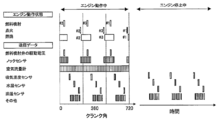
- Example 1 of this invention It is a schematic block diagram of the engine control system to which Example 1 of this invention was applied. It is a figure which shows the structure of the hub unit and the control unit in Example 1 of this invention. It is a figure which shows the operating state of the engine in Example 1 of this invention, and the sensor data which is transmitted corresponding to the operating state of an engine. In the first embodiment of the present invention, it is a figure which shows that the time for executing one cycle of a scheduling table is different depending on the case where an engine is operating at a low rotation speed and the case where the engine is operating at a high rotation speed. It is a timing diagram of the communication system in Example 1 of this invention.
- Example 1 of this invention It is a figure which shows an example of the data frame transmitted from the master and the received frame received by a master in Example 1 of this invention. It is a figure which shows the structure of the hub unit and the control unit in Example 2 of this invention. It is a figure which shows the engine operating state and the transmission schedule of a sensor data in Example 2 of this invention. It is a figure which shows the structure of the hub unit and the control unit in Example 3 of this invention. It is a figure which shows the data frame structure in the serial communication of Example 3 of this invention. It is a figure which showed the sensor data to be transmitted in the serial communication which applied Example 4 of this invention on the time axis. It is a figure which shows the sensor data transmitted by the serial communication when Example 5 of this invention is applied. It is a schematic block diagram of Example 6 of this invention. It is a schematic block diagram of Example 7 of this invention.
- Example 1 As Example 1 of the present invention, an example applied to a control system of an engine provided in a vehicle will be described.
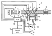
- FIG. 1 is a schematic configuration diagram of an engine control system to which the first embodiment of the present invention is applied.
- the engine 1 includes an intake passage 3 that takes in air from the atmosphere.
- an air cleaner 4 for filtering foreign substances in the atmosphere
- an air flow meter 6 for measuring the intake air amount
- a throttle valve 5 and a throttle position sensor 22 for adjusting the intake air amount
- a temperature of the intake air are measured.
- the intake air temperature sensor 19 is provided. The intake air is taken into the combustion chamber 2 by the opening / closing operation of the intake valve 8.
- the combustion chamber 2 is provided with a fuel injection valve 7 and a spark plug 9 for igniting the mixed air.
- a knock sensor 10 for detecting abnormal combustion is provided on the outer wall of the combustion chamber 2.
- a piston 11 and a crankshaft 12 that convert the pressure due to combustion into rotary motion are provided.
- the crankshaft 12 is provided with a crank angle sensor 13 that measures the angle of rotation.
- Exhaust after combustion is discharged to the exhaust passage by opening and closing the exhaust valve 14.
- the exhaust passage is provided with a catalyst 15 for purifying the exhaust gas.
- a water temperature sensor 20 for measuring the cooling water temperature of the engine 1 and an oil temperature sensor 21 for measuring the temperature of the lubricating oil are attached.
- the control system of the engine 1 will be described.
- the engine 1 of the first embodiment includes sensors for measuring the state of the engine, such as an air flow meter 6, a throttle position sensor 22, a knock sensor 10, an intake air temperature sensor 19, a crank angle sensor 13, a water temperature sensor 20, and an oil temperature sensor 21. It is equipped with system parts.
- actuator system parts such as a throttle valve 5, a fuel injection valve 7, an intake valve 8, and an exhaust valve 14 that adjust the operating state of the engine 1 by physical drive.
- the signal line for transmitting the sensor data measured by the sensor system parts is connected to the hub unit 16 which is a data aggregation unit, and the sensor data is aggregated in the hub unit 16.
- the sensor data aggregated in the hub unit 16 is transmitted to the control unit (control unit) 18 via the serial communication line 17 for serial communication of the sensor data.
- the control unit 18 calculates an optimum operation parameter of the actuator system component based on the sensor data, and this operation parameter is transmitted to the hub unit 16 via the serial communication line 17.
- the hub unit 16 drives the actuator or transmits a drive signal based on the received operating parameters.
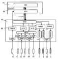
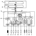
- FIG. 2 is a diagram showing a configuration of a hub unit 16 and a control unit 18 in the first embodiment of the present invention.
- the hub unit 16 is a sensor system component (air flow meter 6, knock sensor 10, crank angle sensor 13, intake air) which is a plurality of detectors for detecting a plurality of operating states of the engine 1 (power generator).
- the temperature sensor 19, the water temperature sensor 20, and the oil temperature sensor 21) are connected.
- These sensor system components are connected to the amplifier AMP provided in the hub unit 16.
- An analog signal, which is a plurality of detection data detected and output by a sensor system component, is amplified by an amplifier AMP.
- the signals from the air flow meter 6, the knock sensor 10, the intake air temperature sensor 19, the water temperature sensor 20, and the oil temperature sensor 21 amplified by the amplifier AMP are converted into digital values by the multiplexer MPX and the analog / digital converter A / D. NS.
- the multiplexer MPX is for switching an input channel for analog / digital conversion according to a command from the second serial communication unit SC2.
- the sensor data converted into digital values (data obtained by converting signals from the air flow meter 6, knock sensor 10, intake air temperature sensor 19, water temperature sensor 20 and oil temperature sensor 21 into digital values) is the second serial communication unit SC2. Will be sent to.
- the sensor data collected in the second serial communication unit SC2 is provided in the control unit 18 which is a control unit that controls the engine 1 which is a power generator from the second serial communication unit SC2 via the serial communication line 17. 1 It is transmitted to the serial communication unit SC1.
- the control unit 18 is provided with an arithmetic unit MC, and the arithmetic unit MC calculates operating parameters of actuator system parts from the sensor data received by the first serial communication unit SC1.
- the calculated operation parameters are transmitted from the arithmetic unit MC to the first serial communication unit SC1 and transmitted to the second serial communication unit SC2 of the hub unit 16 via the serial communication line 17.
- the second serial communication unit SC2 determines the type of the received operation parameter, and generates the driver DRIVER signal from the driver DRIVER of the actuator system parts (fuel injection valve 7, spark plug 9, throttle valve 5) or the operation parameter. It is transmitted to the pulse generator PWM1 and the pulse generator PWM2.
- the pulse generator PWM1 generates a PWM waveform indicating the injection timing and injection amount of the fuel injection valve 7.
- the frequency and the phase indicating the injection timing are generated based on the crank angle measured from the crank angle sensor 13 and the injection timing which is an operation parameter calculated by the control unit 18.
- the pulse width indicating the injection amount is set based on the operation parameter calculated by the control unit 18.
- the pulse generator PWM1 generates a pulse wave that operates the spark plug 9.
- the frequency and phase indicating the ignition timing in the pulse wave are generated based on the crank angle measured from the crank angle sensor 13 and the operation parameters of the ignition timing calculated by the control unit 18.
- the pulse generator PWM2 generates a PWM waveform that drives the throttle valve 5.
- the opening degree of the throttle valve 5 is determined by the duty ratio of the PWM waveform.
- the duty ratio is an operating parameter calculated by the arithmetic unit MC of the control unit 18.
- the pulse generator PWM2 generates and outputs a PWM wave based on the signal of the throttle position sensor 22 input via the amplifier AMP so that the target throttle opening is reached.
- the crank angle sensor 13 detects the rotation of the crankshaft 12 and generates a pulse signal having a frequency corresponding to the rotation speed.
- the pulse signal from the crank angle sensor 13 is amplified by the amplifier AMP.
- the pulse signal amplified by the AMP is input to the timer 25, the number of pulses is counted, and this count value is output from the timer 25. This count value indicates the crank angle of the engine 1, and the intake process, the compression process, the expansion stroke, and the exhaust process of the combustion chamber 2 can be discriminated from the measured crank angle.
- the crank angle data is transmitted to the first serial communication unit SC1 provided in the control unit 18.
- the hub unit 16 acquires not only the sensor data of the sensor system components but also the operation signals of the actuator system components as sensor data and transmits them to the control unit 18 via the serial communication line 17.
- the first embodiment shows a mode in which the operating voltage and the operating current value output from the driver of the fuel injection valve 7 are converted into digital values by an A / D converter and transmitted to the second serial communication unit SC2.
- the communication method has a sufficient transmission speed (communication speed) for the amount of detected sensor data, all sensor data may be transmitted sequentially, but it is necessary to use a high-cost communication method. ..
- FIG. 3 shows an example in which Example 1 of the present invention is applied to a control device of a 3-cylinder engine as a power generator.
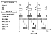
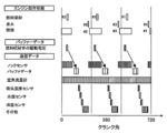
- FIG. 3 is a diagram showing an operating state of the engine 1 and sensor data transmitted corresponding to the operating state of the engine 1.
- the transmitted sensor data is determined by the operating state of the engine 1, that is, the process of fuel injection, ignition, and combustion. Since the process of the engine 1 correlates with the crank angle measured based on the crank angle sensor 13 of the engine 1, the order in which the plurality of sensor data are transmitted based on the crank angle (based on the crank angle) is set. Will be done.
- the drive voltage and drive current of the fuel injection valve 7 are transmitted to the control unit 18 by serial communication via the serial communication line 17.
- the drive voltage and drive current are transmitted only at the timing when the fuel injection valve 7 is driven, and are not transmitted during other periods.
- the sensor data is serially transmitted only during the period when the sensor data required for control can be obtained. Therefore, it is not necessary to transmit data unnecessary for control, and the amount of sensor data communication via serial communication can be reduced.
- the spark plug 9 ignites the mixed air and starts combustion.
- the sensor data of the knock sensor 10 is transmitted to the control unit 18 via the serial communication line 17 in order to detect abnormal combustion.
- the sensor data of the knock sensor 10 is transmitted at the timing of the combustion period. It is not transmitted in other periods such as the intake process where knocking does not occur. Since the sensor data is serially transmitted only during the period in which knocking may occur, it is not necessary to transmit unnecessary data, and the amount of sensor data communication via the serial communication line 17 can be reduced.
- the sensor data of the air flow meter 6 since the sensor data of the air flow meter 6 always needs the sensor data that follows the pulsation of the intake air, it needs to be constantly transmitted without depending on the combustion stroke of the engine 1. Therefore, it is always transmitted via serial communication regardless of the crank angle indicating the operating state of the engine 1.
- the intake air temperature sensor 19, the water temperature sensor 20, and the oil temperature sensor 21 are data that do not depend on the combustion cycle of the engine 1. Since these temperature sensors (intake air temperature sensor 19, water temperature sensor 20 and oil temperature sensor 21) gradually change from several seconds to several tens of seconds depending on the temperature of the engine 1, the fluctuation of the sensor data is slow.
- the drive voltage and drive current of the fuel injection valve 7 and the sensor data of the knock sensor 10 are transmitted while avoiding the transmission timing.
- sensor data with slow fluctuations is transmitted during this period.
- the sensor data of all the sensors is not always transmitted, but the sensor data is transmitted only for the period required for control. Further, the low-speed sensor data is serially communicated based on the scheduling table 26 (communication order setting unit provided in the control unit 18) in which the order of transmission is determined in advance so that the sensor data is transmitted in a period when the communication volume is relatively small. Sensor data can be transmitted efficiently.
- the scheduling table 26 is a communication order setting unit in which the communication order for serial communication from the hub unit 16 which is a data aggregation unit of a plurality of detection data to the control unit 18 which is a control unit is preset.
- FIG. 4 is a diagram showing that in the first embodiment, the time for executing one cycle of the scheduling table 26 differs depending on whether the engine 1 is operating at a low rotation speed or a high rotation speed.
- the sensor data transmitted via the serial communication line 17 is determined based on the crank angle of the engine 1.
- the scheduling table 26 is executed for one cycle depending on whether the engine 1 is operating at low rotation speed or high rotation speed. The time to do is different.
- the data transmitted by the serial communication is the engine 1. It has the characteristic of changing according to the operating speed.
- serial Peripheral Interface Serial Peripheral Interface
- FIG. 5 is a timing diagram of the communication method in the first embodiment.
- the first serial communication unit SC1 provided in the control unit 18 serves as a master in SPI communication
- the second serial communication unit SC2 provided in the hub unit 16 serves as a slave in SPI communication.
- SPI communication data is transmitted and received using four communication lines (CS, SCK, MOSI, MISO).
- there is only one CS line because the communication is one-to-one between the control unit 18 and the hub unit 16.
- SCK is a clock signal
- MOSI is transmission data from the master
- MISO is reception data from the slave.
- CS When CS becomes low level in frame 1, a clock signal is transmitted from SCK. At the same time, a signal requesting sensor data (DATA1) is transmitted from MOSI.
- DATA1 Signal requesting sensor data
- the value of the sensor data (DATA1) is transmitted from the slave via MISO at the timing when the CS becomes low level in frame 2.
- a signal requesting sensor data (DATA2) is transmitted from the next master to MOSI.
- the sensor data (DATA2) value is transmitted from the slave via MISO.
- the slave repeatedly returns the sensor data requested by the master to send and receive data.
- the order and timing of the sensor data requested by the master follows a schedule based on the crank angle.
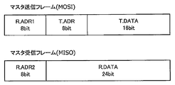
- FIG. 6 is a diagram showing an example of a data frame transmitted from the master and a received frame received by the master.
- the bit length of the transmission frame and the reception frame in the first embodiment was 32 bits.
- the transmission frame consists of an 8-bit reception address (RADR1), an 8-bit transmission address (TADR), and a 16-bit transmission data (T.DATA).
- the receiving address (RADR1) indicates which sensor data is requested from the hub unit 16, and the transmitting address (TADR) indicates which actuator the operating parameter calculated by the control unit 18 belongs to. ..
- the transmission data (T. DATA) indicates the value of the operation parameter.
- the reception frame consists of an 8-bit reception address (R.ADR2) and a 24-bit reception data (R.DATA).
- the reception address (R.ADR2) indicates which sensor the received data belongs to, and the reception data (R.DATA) indicates the value of the sensor data.
- the first embodiment of the present invention has a scheduling function in which the order of sensor signals transmitted from the hub unit 16 to the control unit 18 is determined, and this scheduling function is powered by the order of the sensor data to be transmitted. It is configured to execute transmission based on a scheduling table 26 determined in advance based on the operating state of the engine 1 which is an apparatus.
- the sensor data is transmitted only for the period required for control without constantly transmitting the data of all the sensors, and the low-speed sensor data is the period when the communication volume is relatively small.
- Sensor data can be efficiently transmitted by performing serial communication based on the scheduling table 26 in which the order of transmission is determined in advance so as to be transmitted to.
- the code for detecting errors in the transmission frame and the reception frame is not included in the above-described first embodiment, a CRC code or the like may be inserted if necessary.
- the effect of the present invention can be obtained by setting the scheduling table 26 in which the order of the sensor data to be transmitted is determined according to the type of the sensor or the actuator connected to the hub unit 16.
- the configuration in which the hub unit 16 is provided with the function of aggregating the signals of the sensor system and the function of driving the actuator based on the operation parameters is shown, but only the function of aggregating the signals of the sensor system is shown.
- the effect of the present invention can be obtained even in the configuration provided with.
- the scheduling table 26 is arranged in the control unit 18, but it is also possible to arrange it in the hub unit 16.
- Example 2 Next, Example 2 of the present invention will be described.
- Example 2 of the present invention a configuration in which the present invention is applied to the control system of the engine 1 will be described.
- the configuration applied to the engine control system will be described as in the first embodiment, and the parts different from the first embodiment will be described in particular.
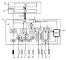
- FIG. 7 is a diagram showing the configuration of the hub unit 16 and the control unit 18 in the second embodiment.
- the difference between the second embodiment and the first embodiment is that the buffer memory 23 is provided in the hub unit 16. As described in the first embodiment, the operating voltage and the operating current of the fuel injection valve 7 are converted into digital values by the A / D converter. The data converted into digital values is stored in the buffer memory 23.
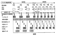
- FIG. 8 is a diagram showing an engine operating state and a sensor data transmission schedule.
- the data stored in the buffer memory 23 is the data at the timing when the fuel injection valve 7 is driven, and the data in other periods is not stored. That is, the sensor data is buffered (stored) only for a predetermined period in which the data required for control is obtained. This can reduce the storage capacity required for the buffer.
- the sensor data of the knock sensor 10 is transmitted to the control unit 18 via the serial communication line 17 in order to detect abnormal combustion.
- the sensor data of the knock sensor 10 is transmitted at the timing of the combustion period, and is not transmitted in another period such as an intake process in which knocking does not occur. Since the sensor data is serially transmitted via the serial communication line 17 only during the period in which the data required for control can be obtained, there is no need to transmit data unnecessary for control and the amount of communication of the sensor data via serial communication. Can be reduced.
- the sensor data of the air flow meter 6 needs the sensor data that follows the pulsation of the intake air, it is necessary to constantly measure it without depending on the combustion stroke of the engine 1. Therefore, it is always transmitted via the serial communication line 17 regardless of the crank angle indicating the operating state of the engine 1.
- the intake air temperature sensor 19, the water temperature sensor 20, and the oil temperature sensor 21 are data that do not depend on the combustion cycle of the engine 1. Since these temperature sensors (intake air temperature sensor 19, water temperature sensor 20 and oil temperature sensor 21) gradually change from several seconds to several tens of seconds depending on the temperature of the engine 1, the fluctuation of the sensor data is slow.
- the drive voltage and drive current of the fuel injection valve 7 and the sensor data of the knock sensor 10 are transmitted while avoiding the transmission timing.
- sensor data with slow fluctuations is transmitted during this period.
- the second embodiment can also obtain the following effects.
- the data of all the sensors is not always transmitted, but the sensor data is transmitted only for the period required for control, and the low-speed sensor data is transmitted during the period when the communication volume is relatively small. ..
- the sensor data can be temporarily stored in the buffer memory 23 and transmitted at different timings within a range that does not cause a control problem.
- the drive voltage and current data of the fuel injection valve 7 are temporarily stored in the buffer memory 23, and the sensor data of the knock sensor 10 and the transmission timing are staggered for serial transmission.
- the data acquired at high speed can be stored in the buffer memory 23 and transmitted by serial communication at low speed, the effect of further reducing the peak value of the communication amount can be obtained.
- Example 3 of the present invention will be described.
- Example 3 describes a configuration in which the present invention is applied to the control system of the engine 1.
- the configuration applied to the engine control system as in the first and second embodiments will be described, and in particular, the parts different from the first and second embodiments will be described.
- FIG. 9 is a diagram showing the configuration of the hub unit 16 and the control unit 18 in the third embodiment. The difference between Example 1 and Example 2 in Example 3 is that the hub unit 16 is provided with the diagnostic unit 24. Although the buffer memory 23 is shown in FIG. 9, the buffer memory 23 can be omitted.
- the diagnostic unit 24 compares the input value and the output value of the driver to determine whether it is normal or abnormal in order to diagnose the failure of the driver unit that drives the spark plug 9 and the throttle valve 5.
- the diagnosis unit 24 determines the abnormality, it transmits a signal indicating that the abnormality has occurred to the second serial communication unit SC2.
- the second serial communication unit SC2 receives the signal of the occurrence of the abnormality from the diagnosis unit 24, the second serial communication unit SC2 transmits the abnormality signal to the arithmetic unit MC of the control unit 18 via the serial communication line 17 and the first serial communication unit SC1.
- FIG. 10 is a diagram showing a data frame configuration in the serial communication of the third embodiment.
- the difference from Example 1 and Example 2 is that the 8-bit diagnostic information is shown in the master reception frame transmitted from the slave second serial communication unit SC2 to the master first serial communication unit SC1.
- the code DIAG is provided.
- the control unit 18 can be notified of the abnormality.
- a bit pattern indicating a failure a normal bit pattern and an abnormal bit pattern are determined in advance.
- Example 3 the same effect as in Example 1 or Example 2 can be obtained, and the following effects can be obtained.
- the diagnosis of the circuit component in the hub unit 16 can be performed in the hub unit 16.
- the diagnostic unit 24 can immediately execute a fail-safe operation such as stopping a failed component, and can enhance safety.
- the diagnostic unit 24 has described an example of diagnosing a failure of the driver unit that drives the spark plug 9 and the throttle valve 5, the AMP, MPX, A / D, and PWM1 which are other components constituting the hub unit 16 are described. , PWM2, timer 25, etc. (failure of hub unit 16) is diagnosed, and the diagnosis result is transmitted (communication) to the arithmetic unit MC via the first serial communication unit SC2 and the first serial communication unit SC1. It is also possible to do.
- Example 4 of the present invention will be described.
- FIG. 11 is a diagram showing the sensor data transmitted in the serial communication to which the fourth embodiment is applied on the time axis. As shown in FIG. 11, the time for executing one cycle of the scheduling table 26 differs depending on whether the engine 1 is operating at a low rotation speed or a high rotation speed.
- additional detection data (additional sensor data) exists, and the types of sensor data to be transmitted increase. That is, the case where the engine 1 as a power generator is operating at a low speed and the case where the engine 1 is operating at a low speed because some of the types of detection data are different depending on whether the engine 1 is operating at a high speed.
- the scheduling table 26 is set so that there are many types of detection data.
- the types of sensor data transmitted by serial communication or when the engine 1 is operating at a lower speed than when the engine 1 is operating at a high speed increases.
- the same effect as that of the first embodiment can be obtained, and the above-mentioned effect can be obtained.
- the detection data to be added to the low rotation range includes, for example, the life data of the actuator or the like.
- Example 5 of the present invention will be described.
- Example 5 of the present invention the configuration applied to the same engine control system as in Example 1 and Example 2 will be described, and in particular, the parts different from those in Example 1 and Example 2 will be described.
- FIG. 12 is a diagram showing sensor data transmitted by serial communication when the present embodiment 5 is applied. As shown in FIG. 12, the fifth embodiment includes a scheduling table 26 that performs different communication depending on whether the engine 1 is operating or stopped.
- the engine 1 When the engine 1 is operating, it follows the scheduling table 26 in which the transmission order of sensor data is determined according to the crank angle. When the engine 1 is stopped, it is scheduled by the arithmetic unit MC provided in the control unit 18 or the timer provided in the first serial communication unit SC1.
- a predetermined threshold value is set for the rotation speed of the engine 1, and the rotation speed can be switched between a case where the rotation speed is lower than this threshold value and a case where the rotation speed is higher than this threshold value.
- the number of revolutions can be calculated from the crank angle.
- the same effect as that of the first embodiment can be obtained, and the above-mentioned effect can be obtained.
- an example of using the scheduling table 26 that performs different communication depending on whether the engine 1 is in the operating state or the stopped state is shown, but the engine 1 is in the stopped state such as idle stop / start. It is also possible to provide a scheduling table 26 for setting communication when transitioning from the operating state to the operating state, and a scheduling table 26 for performing different communication depending on the operating state of the engine 1 such as when transitioning from the operating state to the stopped state.
- Example 6 of the present invention will be described.
- the sixth embodiment is an example of being applied to a control device of an electric motor as a power generation device other than the engine 1.
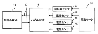
- FIG. 13 is a schematic configuration diagram of the sixth embodiment.
- the power generator is an electric motor 31, and the scheduling table 26 arranged in the control unit 18 or the hub unit 16 has an order of sensor signals transmitted (communication) based on the rotation angle of the electric motor 31. It has been decided.
- a resolver can be used as the rotation angle sensor 27 that detects the rotation angle of the electric motor 31.
- the sensor data transmitted to the control unit 18 via the hub unit 16 and the serial communication line 17 includes a temperature sensor signal detected by the temperature sensor 28, a current sensor signal detected by the current sensor 29, and a voltage sensor 30. It is a detected voltage detection signal or the like.
- the internal configuration of the control unit 18 is the same as the configuration of the first embodiment, detailed description thereof will be omitted. Further, the internal configuration of the hub unit 16 is composed of the second serial communication unit SC2, the amplifier AMP, the multiplexer MPX, the driver DRIVER, the pulse generator PWM1, the pulse generator PWM2, and the timer 25, as in the configuration of the first embodiment. NS.
- the data of all the sensors are controlled instead of being constantly transmitted based on the rotation angle of the electric motor 31 indicating the operating state of the electric motor 31. Transmit sensor data only for the required period. Further, the low-speed sensor data can be efficiently transmitted by serial communication based on the scheduling table 26 in which the order of transmission is determined in advance so that the low-speed sensor data is transmitted in a period when the communication amount is relatively small.
- the sixth embodiment it is possible to realize a vehicle control device capable of efficiently transmitting a large amount of sensor data and stably executing data processing and control in serial transmission at a limited transmission speed. Can be done.
- Example 7 of the present invention will be described.
- This Example 7 is an example applied to an automatic driving device of a vehicle.
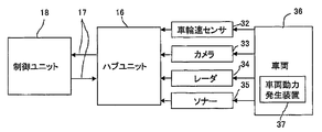
- FIG. 14 is a schematic configuration diagram of the seventh embodiment.
- the power generator is an internal combustion engine or an electric motor, a brake, and a steering (vehicle power generator 37) of the vehicle 36, and the scheduling table 26 arranged in the control unit 18 or the hub unit 17 is based on the speed of the vehicle 36. The order of the sensor signals to be transmitted is determined.
- a wheel speed sensor 32 can be used as a sensor for detecting the speed of the wheels of the vehicle 36. Further, as the sensor data transmitted from the hub unit 16 to the control unit 18 by the serial communication line 17, the image pickup data captured by the camera 33, the distance data to the object detected by the radar 34, and the sonar 35 are detected. There is distance data with the object.
- the internal configuration of the control unit 18 is the same as the configuration of the first embodiment, detailed description thereof will be omitted. Further, the internal configuration of the hub unit 16 is composed of the second serial communication unit SC2, the amplifier AMP, the multiplexer MPX, the driver DRIVER, the pulse generator PWM1, the pulse generator PWM2, and the timer 25, as in the configuration of the first embodiment.
- the seventh embodiment is based on the same technical idea as that of the first embodiment, and is based on the vehicle speed of the vehicle 36 to control the vehicle power generator 37 of the vehicle 36 instead of constantly transmitting the data of all the sensors. Transmit sensor data only for the required period. Further, the low-speed sensor data can be efficiently transmitted by serial communication based on the scheduling table 26 in which the order of transmission is determined in advance so that the low-speed sensor data is transmitted in a period when the communication amount is relatively small.
- a vehicle control device in serial transmission at a limited transmission speed, a vehicle control device (provided with a vehicle) capable of efficiently transmitting a large amount of sensor data and stably executing data processing and control. (Vehicle control device) can be realized.
- the power generator in the seventh embodiment may be the internal combustion engine of the vehicle 36 or the electric motor 31.
Landscapes
- Engineering & Computer Science (AREA)
- Mechanical Engineering (AREA)
- General Engineering & Computer Science (AREA)
- Combustion & Propulsion (AREA)
- Chemical & Material Sciences (AREA)
- Computer Hardware Design (AREA)
- Microelectronics & Electronic Packaging (AREA)
- Sustainable Development (AREA)
- Power Engineering (AREA)
- Transportation (AREA)
- Sustainable Energy (AREA)
- Life Sciences & Earth Sciences (AREA)
- Combined Controls Of Internal Combustion Engines (AREA)
- Electric Propulsion And Braking For Vehicles (AREA)
Abstract
限られた伝送速度におけるシリアル通信において、大量のセンサデータを効率よく送信し、データ処理や制御を安定的に実行することが可能な車両制御装置を実現する。 車両制御装置は、動力発生装置1の複数の動作状態を検知する複数の検知器(6、10、13、19、20、21)と、複数の検知器から出力される複数の検知データに基づいて動力発生装置を制御する制御部18と、複数の検知データを集約するデータ集約部18と、複数の検知データを前記データ集約部16から制御部18へシリアル通信するためのシリアル通信線17と、複数の検知データのデータ集約部16から制御部18へシリアル通信する通信順序が予め設定された通信順序設定部26とを備える。
Description
本発明は、車両制御装置に関する。
近年、自動車の安全性、快適性を高めるためにドライバーアシスト機能や自動運転機能の高性能化が進んでいる。また、車両の動力発生させる内燃機関やモータにおいても高効率化が求められている。これらを実現するためにセンサやアクチュエータの種類や個数が増加している。
これにより、センサ、アクチュエータを接続するハーネスが増加し、車両のスペース、重量、製造工数における課題となっている。
多数のセンサ信号を少ないハーネスで送信するためにはシリアル伝送を用いることが有効である。シリアル伝送は一つの伝送路を用いて多数のセンサデータを逐次的に送信するため、各々のセンサデータに要求される伝送速度に応じて伝送するデータの優先順位を設定する必要がある。
このような車載用のシリアル伝送の技術が特許文献1に開示されている。
特許文献1に記載の技術では、シリアル伝送において複数のセンサデータの伝送要求が重複した時に、重複したセンサデータの内、優先度の高いセンサデータを判定して送信する判定機能を設けている。
この機能により伝送するセンサデータが重複した場合でも、センサデータの伝送遅れが制御に与える影響を低減することができる。
特許文献1に示された技術は、センサの数やデータ量が比較的少なく伝送路の伝送速度が十分に確保できている場合には有効である。
しかしながら、多数のセンサからの大量のセンサデータを伝送速度で送信する場合、優先度を判定する回数が増加し、優先度の低いセンサデータの送信が極端に遅れるなど、送信に遅れが生じやすくなる。
また、送信データの遅延時間が変動し、ローバスフィルタ処理などの遅延時間に依存するデータ処理に不都合が生じる。
本発明は、上述のような課題を解決するためになされたもので、その目的は、限られた伝送速度におけるシリアル通信において、大量のセンサデータを効率よく送信し、データ処理や制御を安定的に実行することが可能な車両制御装置を実現することである。
上記目的を達成するため、本発明は次のように構成される。
車両制御装置において、動力発生装置の複数の動作状態を検知する複数の検知器と、前記複数の検知器から出力される複数の検知データに基づいて前記動力発生装置を制御する制御部と、前記複数の検知データを集約するデータ集約部と、前記複数の検知データを前記データ集約部から前記制御部へシリアル通信するためのシリアル通信線と、前記複数の検知データの前記データ集約部から前記制御部へシリアル通信する通信順序が予め設定された通信順序設定部と、を備える。
限られた伝送速度におけるシリアル通信において、大量のセンサデータを効率よく送信し、データ処理や制御を安定的に実行することが可能な車両制御装置を実現する。
以下、本発明の実施形態について添付図面を参照して説明する。
(実施例1)
本発明の実施例1として、車両に備えられたエンジンの制御システムに適用した例を説明する。
本発明の実施例1として、車両に備えられたエンジンの制御システムに適用した例を説明する。
図1は、本発明の実施例1を適用したエンジン制御システムの概略構成図である。
図1において、エンジン1は、大気中の空気を取り込む吸気通路3を備えている。吸気通路3には、大気中の異物を濾過するエアクリーナ4と、吸入空気量を計測する空気流量計6と、吸入空気量を調整するスロットルバルブ5及びスロットルポジションセンサ22、吸入空気の温度を計測する吸気温度センサ19が設けられている。吸入空気は吸気バルブ8の開閉動作により燃焼室2へ取り込まれる。
燃焼室2には燃料噴射弁7と混合空気に点火する点火プラグ9が設けられている。燃焼室2の外壁には、異常燃焼を検知するノックセンサ10が設けられている。燃焼による圧力を回転運動に変換するピストン11とクランクシャフト12が設けられている。クランクシャフト12には回転角を計測するクランク角センサ13が設けられている。
燃焼後の排気は排気バルブ14の開閉により排気通路へ排出される。排気通路には排ガスを浄化する触媒15が設けられている。また、設置場所の図示は省略しているがエンジン1の冷却水温度を計測する水温センサ20や、潤滑オイルの温度を計測する油温センサ21が取り付けられている。
上記エンジン1の制御システムについて説明する。
本実施例1のエンジン1には、空気流量計6スロットルポジションセンサ22、ノックセンサ10、吸気温度センサ19、クランク角センサ13、水温センサ20、油温センサ21などのエンジンの状態を計測するセンサ系部品が備えられている。
また、スロットルバルブ5、燃料噴射弁7、吸気バルブ8、排気バルブ14など物理的な駆動によりエンジン1の運転状態を調整するアクチュエータ系部品を備えている。
センサ系部品により計測したセンサデータを伝送する信号線は、データ集約部であるハブユニット16に接続され、センサデータはハブユニット16に集約される。ハブユニット16に集約されたセンサデータは、センサデータをシリアル通信するためのシリアル通信線17を介して制御ユニット(制御部)18へ伝送される。制御ユニット18は、センサデータに基づいてアクチュエータ系部品の最適な動作バラメータを演算し、この動作パラメータはシリアル通信線17を介してハブユニット16へ伝送される。ハブユニット16は、受信した動作パラメータに基づいてアクチュエータを駆動または駆動信号を送信する。
図2は、本発明の実施例1におけるハブユニット16と制御ユニット18の構成を示す図である。
図2において、ハブユニット16には、エンジン1(動力発生装置)の複数の動作状態を検知する複数の検知器であるセンサ系部品(空気流量計6、ノックセンサ10、クランク角センサ13、吸気温度センサ19、水温センサ20、油温センサ21)が接続される。これらのセンサ系部品は、ハブユニット16に設けたアンプAMPに接続される。センサ系部品により検出し、出力される複数の検知データであるアナログ信号がアンプAMPにより増幅される。
アンプAMPにより増幅された、空気流量計6、ノックセンサ10、吸気温度センサ19、水温センサ20及び油温センサ21からの信号はマルチプレクサMPXとアナログ/デジタル変換器A/Dによりデジタル値に変換される。マルチプレクサMPXは第2シリアル通信部SC2からの指令によりアナログ/デジタル変換する入力チャネルを切り替えるためのものである。デジタル値に変換されたセンサデータ(空気流量計6、ノックセンサ10、吸気温度センサ19、水温センサ20及び油温センサ21からの信号がデジタル値に変換されたデータ)は第2シリアル通信部SC2に送信される。
第2シリアル通信部SC2に集約されたセンサデータは、第2シリアル通信部SC2からシリアル通信線17を介して、動力発生装置であるエンジン1を制御する制御部である制御ユニット18に設けた第1シリアル通信部SC1に伝送される。制御ユニット18には演算装置MCが設けられ、演算装置MCにより、第1シリアル通信部SC1で受信したセンサデータからアクチュエータ系部品の動作パラメータが演算される。
演算された動作パラメータは、演算装置MCから第1シリアル通信部SC1に送信され、シリアル通信線17を介してハブユニット16の第2シリアル通信部SC2に伝送される。第2シリアル通信部SC2は受信した動作パラメータの種類を判定し、動作パラメータをアクチュエータ系部品(燃料噴射弁7、点火プラグ9、スロットルバルブ5)のドライバDRIVERもしくは動作パラメータからドライバDRIVERの信号を生成するパルス発生器PWM1及びパルス発生器PWM2に伝送する。
パルス発生器PWM1は燃料噴射弁7の噴射時期と噴射量を示すPWM波形を生成する。このPWM波形において、噴射時期を示す周波数及び位相は、クランク角センサ13から計測したクランク角度と制御ユニット18により演算された動作パラメータである噴射時期に基づき生成される。噴射量を示すパルス幅は制御ユニット18により演算された動作パラメータに基づきパルス幅が設定される。
また、パルス発生器PWM1は、点火プラグ9を動作させるパルス波を生成する。パルス波において点火時期時期を示す周波数及び位相は、クランク角センサ13から計測したクランク角度と制御ユニット18により演算された点火時期の動作パラメータに基づき生成される。
パルス発生器PWM2は、スロットルバルブ5を駆動するPWM波形を生成する。スロットルバルブ5の開度はPWM波形のデューティ比によって決まる。デューティ比は制御ユニット18の演算装置MCにより演算される動作パラメータである。パルス発生器PWM2は目標のスロットル開度となるように、アンプAMPを介して入力されるスロットルポジションセンサ22の信号に基づいてPWM波を生成して出力する。
クランク角センサ13はクランクシャフト12の回転を検出して回転速度に応じた周波数のパルス信号を発生する。クランク角センサ13からのパルス信号はアンプAMPにより増幅される。AMPにより増幅されたパルス信号は、タイマー25に入力され、パルス数がカウントされ、このカウント値がタイマー25から出力される。このカウント値は、エンジン1のクランク角度を示し、測定したクランク角度から燃焼室2の吸気工程、圧縮工程、膨張行程、排気工程を判別することができる。クランク角データは制御ユニット18に設けた第1シリアル通信部SC1に送信される。
ハブユニット16は、図2に示すように、センサ系部品のセンサデータだけでなくアクチュエータ系部品の動作信号もセンサデータとして取得し、シリアル通信線17を介して制御ユニット18へ伝送する。
本実施例1では燃料噴射弁7のドライバから出力される動作電圧及び動作電流値をA/D変換器によりデジタル値に変換し第2シリアル通信部SC2へ送信する形態を示している。
上記の構成のように、センサ系部品のセンサデータやアクチュエータ系部品の動作パラメータを、シリアル通信線17を介して伝送(通信)する場合、大量のセンサデータについてリアルタイム性を満たして伝送(通信)する必要がある。
検出したセンサデータのデータ量に対して十分な伝送速度(通信速度)を備えた通信方式であれば、すべてのセンサデータを逐次伝送すればよいが、高コストな通信方式を使用する必要がある。
限られた伝送速度を用いたシリアル通信においては、データ処理や制御を安定的に実行するために効率よくセンサデータを送信する必要がある。
以下、上記のような効率よくセンサデータを送信することを達成するために構成された伝送スケジューリング機能を説明する。
図3に動力発生装置として3気筒エンジンの制御装置に本発明の実施例1を適用した例を示す。図3はエンジン1の動作状態と、エンジン1の動作状態に対応して送信されるセンサデータを示す図である。送信されるセンサデータはエンジン1の動作状態、即ち燃料噴射、点火、燃焼の工程により決定される。このエンジン1の工程は、エンジン1のクランク角センサ13に基づいて測定したクランク角に相関があるため、複数のセンサデータはクランク角に基づいて(クランク角を基準として)送信される順序が設定される。
図3に示した伝送スケジュールを説明する。図3に示した例では、燃料噴射、点火、燃焼噴射が、気筒ナンバー2、3、1の順で行われる。
まず、燃料噴射弁7により燃料が噴射される。この時、燃料噴射弁7の開弁及び閉弁のタイミングのばらつきを検出するために、燃料噴射弁7の駆動電圧や駆動電流がシリアル通信線17によるシリアル通信で制御ユニット18へ伝送される。この駆動電圧及び駆動電流が送信されるのは燃料噴射弁7が駆動するタイミングのみであり、他の期間では伝送しない。
つまり、制御に必要なセンサデータが得られる期間に限定してセンサデータをシリアル伝送する。そのため、制御に不要なデータを送信する必要がなくシリアル通信を介したセンサデータの通信量を削減することができる。
次に、点火プラグ9により混合空気が着火され燃焼が始まる。このとき、異常な燃焼を検知するためにノックセンサ10のセンサデータがシリアル通信線17を介して制御ユニット18へ伝送される。このノックセンサ10のセンサデータが送信されるのは燃焼期間のタイミングである。ノッキングの発生しない吸気工程などの他の期間では伝送しない。
ノッキングが発生する可能性のある期間に限定してセンサデータをシリアル伝送するので、不要なデータを送信する必要がなくシリアル通信線17を介したセンサデータの通信量を削減できる。
ノッキングが発生する可能性のある期間に限定してセンサデータをシリアル伝送するので、不要なデータを送信する必要がなくシリアル通信線17を介したセンサデータの通信量を削減できる。
次に、空気流量計6のセンサデータは吸気の脈動に追従したセンサデータが常時必要であるためエンジン1の燃焼行程に依存せず常時伝送する必要がある。そのため、エンジン1の動作状態を示すクランク角に依存せず常時シリアル通信を介して伝送される。
吸気温度センサ19、水温センサ20及び油温センサ21は、エンジン1の燃焼サイクルに依存しないデータである。これらの温度センサ(吸気温度センサ19、水温センサ20及び油温センサ21)は、エンジン1の温度によって数秒から数十秒かけて徐々に変化するためセンサデータの変動が低速である。
したがって、このように低速で変化するセンサデータはエンジン1の動作サイクルの中で伝送するセンサデータが少ない空き時間に伝送すれば十分である。
つまり、燃料噴射弁7の駆動電圧及び駆動電流やノックセンサ10のセンサデータが送信されるタイミングを避けて送信する。また、その他のセンサデータとして、変動の遅いセンサデータをこの期間に伝送する。
以上のように、エンジン1の動作状態を示すクランク角度に基づいて、すべてのセンサのデータを常時伝送するのではなく、制御に必要な期間のみのセンサデータを伝送する。
さらに、低速なセンサデータは比較的通信量が少ない期間に伝送するように予め伝送する順番を決定したスケジューリングテーブル26(制御ユニット18に備えられている通信順序設定部)に基づいてシリアル通信することで効率よくセンサデータを送信することができる。スケジューリングテーブル26は、複数の検知データのデータ集約部であるハブユニット16から制御部である制御ユニット18へシリアル通信する通信順序が予め設定された通信順序設定部である。
さらに、低速なセンサデータは比較的通信量が少ない期間に伝送するように予め伝送する順番を決定したスケジューリングテーブル26(制御ユニット18に備えられている通信順序設定部)に基づいてシリアル通信することで効率よくセンサデータを送信することができる。スケジューリングテーブル26は、複数の検知データのデータ集約部であるハブユニット16から制御部である制御ユニット18へシリアル通信する通信順序が予め設定された通信順序設定部である。
図4は、実施例1において、エンジン1が低回転で動作している場合と高回転で動作している場合とで、スケジューリングテーブル26を1サイクル実行する時間が異なることを示す図である。上述したように、シリアル通信線17を介して伝送するセンサデータはエンジン1のクランク角度に基づいて決定される。そうすると、図4に示すように、送信されるセンサデータを時間軸で見るとエンジン1が低回転で動作している場合と高回転で動作している場合とで、スケジューリングテーブル26を1サイクル実行する時間が異なる。
つまり、動力発生装置としてのエンジン1の動作状態を示すクランク角に基づいて、伝送するセンサデータの順番を予め決定したスケジューリングテーブル26に基づいてシリアル通信するとシリアル通信で送信されるデータがエンジン1の動作速度に応じて変動する特徴を持つ。
上記のように、シリアル通信線17により伝送するセンサデータを予め決められた順番で送信する(動力発生装置であるエンジン1の動作状態に基づいて設定された順番で送信(通信)する)ことにより、複数のセンサデータの送信要求が衝突することがない。これにより、センサデータの遅延時間が固定されるのでセンサデータのサンプリング周期に依存するローパスフィルタ処理などデータ処理を不具合なく実行することができる。
次に、本実施例1で示したシリアル通信の具体的方式の一例を説明する。
本実施例1ではシリアル通信方式として全二重通信であるSPI(Serial Peripheral Interface)通信を用いた例を説明する。
図5は、本実施例1における通信方式のタイミング図である。本方式では制御ユニット18に設けた第1シリアル通信部SC1がSPI通信におけるマスターとなり、ハブユニット16に設けた第2シリアル通信部SC2がSPI通信におけるスレーブとなる。SPI通信では4線の通信線(CS、SCK、MOSI、MISO)を使用してデータの送受信を行う。
まず、CSの論理レベルの変化により通信するスレーブを選択する。本実施例1の場合、制御ユニット18とハブユニット16の1対1通信であるためCS線は1本である。SCKはクロック信号、MOSIはマスターからの送信データ、MISOはスレーブからの受信データである。
フレーム1でCSがローレベルになると、SCKからクロック信号が送信される。これと同時にMOSIからセンサデータ(DATA1)を要求する信号が送信される。
次に、フレーム2でCSがローレベルとなるタイミングでスレーブからMISOを介してセンサデータ(DATA1)の値が送信される。同時に、フレーム2では、次のマスターからMOSIにセンサデータ(DATA2)を要求する信号が送信される。
次のフレーム3でスレーブからMISOを介してセンサデータ(DATA2)の値が送信される。このように、マスターが要求したセンサデータをスレーブが返すことを繰り返してデータを送受信する。マスターが要求するセンサデータの順番およびタイミングは、クランク角に基づいたスケジュールに従う。
図6は、マスターから送信されるデータフレーム及びマスターが受信する受信フレームの一例を示す図である。
本実施例1での送信フレーム及び受信フレームのビット長は、32bitとした。
送信フレームは、8bitの受信アドレス(R.ADR1)、8bitの送信アドレス(T.ADR)、16bitの送信データ(T.DATA)から成る。受信アドレス(R.ADR1)は、ハブユニット16に対してどのセンサのデータを要求するかを示し、送信アドレス(T.ADR)は制御ユニット18で演算した動作パラメータがどのアクチュエータのものかを示す。送信データ(T.DATA)は動作パラメータの値を示している。
受信フレームは8bitの受信アドレス(R.ADR2)と24bitの受信データ(R.DATA)からなる。受信アドレス(R.ADR2)は受信したデータがどのセンサのものかを示し、受信データ(R.DATA)はセンサデータの値を示している。
以上のように、本発明の実施例1は、ハブユニット16から制御ユニット18へ送信するセンサ信号の順番を決めたスケジューリング機能を有し、このスケジューリング機能は、送信するセンサデータの順番が動力発生装置であるエンジン1の動作状態に基づいて予め決定されたスケジューリングテーブル26に基づいて送信を実行するように構成される。
つまり、エンジン1の動作状態を示すクランク角度に基づいて、すべてのセンサのデータを常時伝送せず制御に必要な期間のみのセンサデータを伝送し、低速なセンサデータは比較的通信量が少ない期間に伝送するように予め伝送する順番を決定したスケジューリングテーブル26に基づいてシリアル通信することで効率よくセンサデータを送信することができる。
よって、限られた伝送速度におけるシリアル伝送において、大量のセンサデータを効率よく送信し、データ処理や制御を安定的に実行することが可能な車両制御装置を実現することができる。
なお、上述した実施例1では、送信フレームおよび受信フレームの誤り検知のための符号が入っていないが、必要に応じでCRCコードなどを挿入しても良い。
また、本実施例1では、すべてのセンサやアクチュエータがハブユニット16に接続される構成を示したが、必ずしもすべてのセンサ、アクチュエータをハブユニット16に接続する必要はない。ハブユニット16に接続されるセンサやアクチュエータの種類に応じて伝送するセンサデータの順番を決定したスケジューリングテーブル26を設定することで、同様に本発明の効果を得ることができる。
また、本実施例1では、ハブユニット16にセンサ系の信号を集約する機能と、動作パラメータに基づいてアクチュエータを駆動する機能を設けた構成を示したが、センサ系の信号を集約する機能のみを備えた構成においても本発明の効果を得ることができる。
また、実施例1においては、スケジューリングテーブル26を制御ユニット18内に配置したが、ハブユニット16内に配置することも可能である。
(実施例2)
次に、本発明の実施例2について説明する。
次に、本発明の実施例2について説明する。
本発明の実施例2として、エンジン1の制御システムに本発明を適用した構成について説明する。本実施例2では、実施例1と同様に、エンジン制御システムに適用した構成について説明し、特に実施例1と異なる部分について説明する。
図7は、本実施例2におけるハブユニット16と制御ユニット18の構成を示す図である。
実施例2が、実施例1と異なるところは、ハブユニット16にバッファメモリ23を設けた点である。実施例1で説明したように、燃料噴射弁7の動作電圧、動作電流はA/D変換装置によってデジタル値に変換される。デジタル値に変換されたデータはバッファメモリ23に保存される。
図8は、エンジン動作状態及びセンサデータの送信スケジュールを示す図である。
図8において、まず、燃料噴射弁7により燃料が噴射される。この時、燃料噴射弁7の開弁及び閉弁のタイミングを検出するために、燃料噴射弁7の駆動電圧や駆動電流がA/D変換によりがデジタル値に変換さバッファメモリ23に保存される。
バッファメモリ23に保存されるデータは燃料噴射弁7が駆動するタイミングでのデータであり、他の期間のデータは保存しない。つまり、制御に必要なデータが得られる所定の期間に限定してセンサデータをバッファリングする(記憶する)。これによりバッファに必要な記憶容量を削減することができる。
次に、点火プラグ9により混合空気に着火すると燃焼が始まる。このとき、異常燃焼を検知するためにノックセンサ10のセンサデータがシリアル通信線17を介して制御ユニット18へ送信される。このノックセンサ10のセンサデータが送信されるのは燃焼期間のタイミングであり、ノッキングの発生しない吸気工程などの他の期間では伝送しない。
制御に必要なデータが得られる期間に限定してセンサデータを、シリアル通信線17を介してシリアル伝送するので、制御に不要なデータを送信する必要がなくシリアル通信を介したセンサデータの通信量を削減することができる。
制御に必要なデータが得られる期間に限定してセンサデータを、シリアル通信線17を介してシリアル伝送するので、制御に不要なデータを送信する必要がなくシリアル通信を介したセンサデータの通信量を削減することができる。
ノックセンサ10のセンサデータをシリアル送信した後、バッファメモリ23に保存された燃料噴射弁7の駆動電圧・駆動電流が送信される。
このように、バッファメモリ23を設けることによって、シリアル通信により伝送するタイミングをずらすことができる。
空気流量計6のセンサデータは吸気の脈動に追従したセンサデータが必要であるためエンジン1の燃焼行程に依存せず常時計測する必要がある。そのため、エンジン1の動作状態を示すクランク角に依存せず常時シリアル通信線17を介して伝送される。
吸気温度センサ19、水温センサ20及び油温センサ21はエンジン1の燃焼サイクルに依存しないデータである。これらの温度センサ(吸気温度センサ19、水温センサ20及び油温センサ21)は、エンジン1の温度によって数秒から数十秒かけて徐々に変化するためセンサデータの変動が低速である。
したがって、このように低速で変化するセンサデータはエンジン1の動作サイクルの中で伝送するセンサデータが少ない空き時間に伝送すれば十分である。
つまり、燃料噴射弁7の駆動電圧及び駆動電流やノックセンサ10のセンサデータが送信されるタイミングを避けて送信する。また、その他のセンサデータとして、変動の遅いセンサデータをこの期間に伝送する。
本実施例2は、実施例1と同様な効果を得ることできる他、以下の効果を得ることができる。
本実施例2においては、すべてのセンサのデータを常時伝送するのではなく、制御に必要な期間のみのセンサデータを伝送し、さらに、低速なセンサデータは比較的通信量が少ない期間に伝送する。これに加えてバッファメモリ23に一時的にセンサデータを保存し、制御上不具合が生じない範囲でタイミングをずらして送信できる。
本実施例2では、燃料噴射弁7の駆動電圧、電流データをバッファメモリ23に一次的に保存し、ノックセンサ10のセンサデータと送信タイミングをずらしてシリアル伝送している。
そのため、よりシリアル通信で伝送するセンサデータを分散させて最大伝送速度を低減することができる。バッファメモリ23を利用して伝送するセンサデータとしては、短い期間の信号を高速で取得する必要があるデータであると、通信量のピーク値を低減する効果が得られる。
また、高速で取得したデータをバッファメモリ23に記憶し、低速でシリアル通信で送信することもできるためより通信量のピーク値を低減する効果が得られる。
(実施例3)
次に、本発明の実施例3について説明する。
次に、本発明の実施例3について説明する。
実施例3は、エンジン1の制御システムに本発明を適用した構成について説明する。本実施例3では、実施例1及び実施例2と同様にエンジン制御システムに適用した構成を説明し、特に実施例1及び実施例2と異なる部分について説明する。
図9は、実施例3におけるハブユニット16と制御ユニット18の構成を示す図である。実施例3の、実施例1及び実施例2と異なるところは、ハブユニット16に診断部24を設けた点である。なお、図9には、バッファメモリ23が記載されているが、バッファメモリ23を省略することも可能である。
診断部24は、点火プラグ9、スロットルバルブ5を駆動するドライバ部の故障を診断するために、ドライバの入力値と出力値を比較して正常か異常かを判定する。診断部24は異常を判定すると、第2シリアル通信部SC2に異常が生じたことを示す信号を送信する。第2シリアル通信部SC2は、診断部24から異常発生の信号を受け取るとシリアル通信線17と第1シリアル通信部SC1を介して制御ユニット18の演算装置MCへ異常信号を送信する。
図10は、本実施例3のシリアル通信におけるデータフレーム構成を示す図である。実施例1及び実施例尾2と異なるところは、スレーブである第2シリアル通信部SC2からマスターである第1シリアル通信部SC1への送信されるマスター受信フレームに診断情報を示す8ビットの診断用符号DIAGを設けたことである。この診断用符号DIAGに診断部24から受け取った異常個所を示すビットパターンを付加することにより、制御ユニット18に異常を通知することができる。故障を示すビットパターンとして、正常時のビットパターンと異常時のビットパターンを予め決定しておく。
実施例3は、実施例1又は実施例2と同様な効果を得ることができる他、以下のような効果を得ることができる。
実施例3によれば、ハブユニット16内の回路部品の診断をハブユニット16内で実行できる。これにより、故障診断のためのデータを制御ユニット18に送信する必要がなく、シリアル通信における通信データ量を削減することができる。また、異常が生じたことを、シリアル通信線17を介して制御ユニット18に送信し、フェールセーフとなるようにアクチュエータ系部品にシリアル通信線17を介して送信すると、異常を判定してからフェールセーフ動作に遷移するまでに時間がかかる。本実施例3のようにハブユニット16に診断部24を設けると、診断部24が、故障した部品を停止するなどのフェールセーフ動作を即時に実行することができ安全性を高めることができる。
なお、診断部24は、点火プラグ9、スロットルバルブ5を駆動するドライバ部の故障を診断する例を記載したが、ハブユニット16を構成する他の部品であるAMP、MPX、A/D、PWM1、PWM2、タイマー25等の故障(ハブユニット16の故障)を診断し、診断結果を第シリアル通信部SC2及び第1シリアル通信部SC1を介して、演算装置MCに送信(通信)するように構成することも可能である。
(実施例4)
次に、本発明の実施例4について説明する。
次に、本発明の実施例4について説明する。
本実施例4では、実施例1及び実施例2と同様に、エンジン制御システムに適用した例を説明し、特に実施例1及び実施例2と異なる部分について説明する。
図11は、本実施例4を適用したシリアル通信において、送信されるセンサデータを時間軸で表した図である。図11に示すように、エンジン1が低回転で動作している場合と高回転で動作している場合とで、スケジューリングテーブル26を1サイクル実行する時間が異なる。
さらに、低回転域においては、図11中に示すように、追加検知データ(追加センサデータ)が存在し、送信されるセンサデータの種類が増加する。つまり、動力発生装置としてのエンジン1が低速で動作している場合と、高速で動作している場合とで検知データの種類の一部が異なり、エンジン1が低速で動作している場合の方が、検知データの種類が多いように設定されているスケジューリングテーブル26を備えている。
本実施例4では、エンジン1が高速で動作している場合よりも低速で動作している場合の方かシリアル通信により送信されるセンサデータの種類が増加する。
エンジン1が高回転である場合、クランク角の回転速度が上がり、シリアル通信線17を介して送信される時間当たりのセンサデータ量が増加する。逆に、エンジン1が低回転である場合は、時間当たりのセンサデータ量が減少する。そうすると、低回転の状態では、シリアル通信で送信できるデータ量に余裕ができるので、他の種類のセンサデータを送信することができ、シリアル通信の伝送効率を有効に利用することができる。
実施例4によれば、実施例1と同様な効果を得ることができる他、上述のような効果を得ることができる。
なお、低回転域に追加する検知データとしては、例えば、アクチュエータ等の寿命データがある。
(実施例5)
次に、本発明の実施例5について説明する。
次に、本発明の実施例5について説明する。
本発明の実施例5では、実施例1及び実施例2と同じエンジン制御システムに適用した構成を説明し、特に実施例1及び実施例2と異なる部分について説明する。
図12は、本実施例5を適用した場合のシリアル通信により送信されるセンサデータを示す図である。図12に示すように、本実施例5ではエンジン1が動作している場合と停止している場合とで異なる通信を行うスケジューリングテーブル26を備えている。
エンジン1が動作中の場合はクランク角に応じてセンサデータの送信順が決められるスケジューリングテーブル26に従う。エンジン1が停止している場合は、制御ユニット18に設けられた演算装置MCまたは、第1シリアル通信部SC1に設けたタイマーによりスケジュールされる。
つまり、エンジン1が動作中はクランク角度を基準としたスケジュールで送信し、エンジンが1停止しているときは時間を基準としたスケジュールで送信する。
上述した2種類のスケジューリングが設定されたスケジューリングテーブル26を切り替えるタイミングとしては、エンジン1の回転速度に所定の閾値を設け、この閾値より回転数が低い場合と高い場合と切り替えることができる。回転数はクランク角度から算出することができる。
これにより、エンジン1が停止し、クランク角に変化がなくなった場合においても必要なデータを、シリアル通信線17を介して送受信することができる。
本実施例5によれば、実施例1と同様な効果を得ることができる他、上述のような効果を得ることができる。
なお、本実施例5では、エンジン1が動作状態である場合と停止状態である場合とで異なる通信を行うスケジューリングテーブル26を使用する例を示したが、アイドルストップ・スタートなどエンジン1が停止状態から動作状態に遷移する場合の通信を設定したスケジューリングテーブル26や、動作状態から停止状態に遷移する場合などエンジン1の動作状態により異なる通信を行うスケジューリングテーブル26を備えることもできる。
なお、本実施例5では、エンジン1が動作状態である場合と停止状態である場合とで異なる通信を行うスケジューリングテーブル26を使用する例を示したが、アイドルストップ・スタートなどエンジン1が停止状態から動作状態に遷移する場合の通信を設定したスケジューリングテーブル26や、動作状態から停止状態に遷移する場合などエンジン1の動作状態により異なる通信を行うスケジューリングテーブル26を備えることもできる。
(実施例6)
次に、本発明の実施例6について説明する。
次に、本発明の実施例6について説明する。
本実施例6は、エンジン1以外の動力発生装置として、電動モータの制御装置に適用した例である。
図13は、本実施例6の概略構成図である。
図13において、動力発生装置は電動モータ31であり、制御ユニット18又はハブユニット16内に配置されたスケジューリングテーブル26は、電動モータ31の回転角を基準として送信(通信)するセンサ信号の順序が決められている。
電動モータ31の回転角を検出する回転角センサ27としてはレゾルバーを用いることができる。また、ハブユニット16及びシリアル通信線17を介して制御ユニット18に送信するセンサデータとしては、温度センサ28により検出される温度センサ信号、電流センサ29により検出される電流センサ信号、電圧センサ30により検出される電圧検出信号等である。
制御ユニット18の内部構成は、実施例1の構成と同様となるので、詳細な説明は省略する。また、ハブユニット16の内部構成は、実施例1の構成と同様に、第2シリアル通信部SC2、アンプAMP、マルチプレクサMPX、ドライバDRIVER、パルス発生器PWM1、パルス発生器PWM2、タイマー25により構成される。
実施例6は、実施例1と同様な技術的思想に基づき、電動モータ31の動作状態を示す電動モータ31の回転角度に基づいて、すべてのセンサのデータを常時伝送するのではなく、制御に必要な期間のみのセンサデータを伝送する。さらに、低速なセンサデータは比較的通信量が少ない期間に伝送するように予め伝送する順番を決定したスケジューリングテーブル26に基づいてシリアル通信することで効率よくセンサデータを送信することができる。
よって、実施例6によれば、限られた伝送速度におけるシリアル伝送において、大量のセンサデータを効率よく送信し、データ処理や制御を安定的に実行することが可能な車両制御装置を実現することができる。
(実施例7)
次に、本発明の実施例7について説明する。
次に、本発明の実施例7について説明する。
本実施例7は、車両の自動運転装置に適用した例である。
図14は、本実施例7の概略構成図である。動力発生装置としては、車両36の内燃機関または電動モータ、ブレーキ、ステアリング(車両動力発生装置37)であり、制御ユニット18又はハブユニット17内に配置されたスケジューリングテーブル26は車両36の速度を基準として送信するセンサ信号の順序が決められている。
車両36の車輪の速度を検出するセンサとしては、車輪速センサ32を用いることができる。また、シリアル通信線17によりハブユニット16から制御ユニット18に送信するセンサデータとしては、カメラ33により撮像された撮像データ、レーダ34により検出された対象物との距離データ、ソナー35により検出された対象物との距離データ等がある。
制御ユニット18の内部構成は、実施例1の構成と同様となるので、詳細な説明は省略する。また、ハブユニット16の内部構成は、実施例1の構成と同様に、第2シリアル通信部SC2、アンプAMP、マルチプレクサMPX、ドライバDRIVER、パルス発生器PWM1、パルス発生器PWM2、タイマー25により構成される。
実施例7は、実施例1と同様な技術的思想に基づき、車両36の車両速度に基づいて、すべてのセンサのデータを常時伝送するのではなく、車両36の車両動力発生装置37の制御に必要な期間のみのセンサデータを伝送する。さらに、低速なセンサデータは比較的通信量が少ない期間に伝送するように予め伝送する順番を決定したスケジューリングテーブル26に基づいてシリアル通信することで効率よくセンサデータを送信することができる。
実施例7は、実施例1と同様な技術的思想に基づき、車両36の車両速度に基づいて、すべてのセンサのデータを常時伝送するのではなく、車両36の車両動力発生装置37の制御に必要な期間のみのセンサデータを伝送する。さらに、低速なセンサデータは比較的通信量が少ない期間に伝送するように予め伝送する順番を決定したスケジューリングテーブル26に基づいてシリアル通信することで効率よくセンサデータを送信することができる。
よって、実施例7によれば、限られた伝送速度におけるシリアル伝送において、大量のセンサデータを効率よく送信し、データ処理や制御を安定的に実行することが可能な車両制御装置(車両に備えられた車両制御装置)を実現することができる。
なお、実施例7における動力発生装置としては、車両36の内燃機関または電動モータ31とすることができる。
1・・・エンジン、2・・・燃焼室、3・・・吸気通路、4・・・エアクリーナ、5・・・スロットルバルブ、6・・・空気流量計、7・・・燃料噴射弁、8・・・吸気バルブ、9・・・点火プラグ、10・・・ノックセンサ、11・・・ピストン、12・・・クランクシャフト、13・・・クランク角センサ、14・・・排気バルブ、15・・・触媒、16・・・ハブユニット、17・・・シリアル通信線、18・・・制御ユニット、19・・・吸気温度センサ、20・・・水温センサ、21・・・油温センサ、22・・・スロットルポジションセンサ、23・・・バッファメモリ、24・・・診断部、25・・・タイマー、26・・・スケジューリングテーブル、27・・・回転角センサ、28…温度センサ、29・・・電流センサ、30・・・電圧センサ、31・・・電動モータ、32・・・車輪速センサ、33・・・カメラ、34・・・レーダ、35・・・ソナー、36・・・車両、37・・・車両動力発生装置、AMP・・・アンプ、MC・・・演算装置、SC1・・・第1シリアル通信部、SC2・・・第2シリアル通信部、
Claims (11)
- 動力発生装置の複数の動作状態を検知する複数の検知器と、
前記複数の検知器から出力される複数の検知データに基づいて前記動力発生装置を制御する制御部と、
前記複数の検知データを集約するデータ集約部と、
前記複数の検知データを前記データ集約部から前記制御部へシリアル通信するためのシリアル通信線と、
前記複数の検知データの前記データ集約部から前記制御部へシリアル通信する通信順序が予め設定された通信順序設定部と、
を備えることを特徴とする車両制御装置。 - 請求項1に記載の車両制御装置において、
前記通信順序設定部に予め設定された前記複数の検知データの通信順序は、前記動力発生装置の動作状態に基づいて設定されることを特徴とする車両制御装置。 - 請求項2に記載の車両制御装置において、
前記データ集約部はハブユニットであり、前記通信順序設定部は、スケジューリングテーブルであることを特徴とする車両制御装置。 - 請求項3に記載の車両制御装置において、
前記ハブユニットは、前記複数の検知器のうちのいずれかの検知器の所定の期間の前記検知データを記憶するバッファメモリを備え、前記バッファメモリに記憶された前記検知データは、前記スケジューリングテーブルに設定された通信順序で、前記ハブユニットから前記制御部にシリアル通信されることを特徴とする車両制御装置。 - 請求項3に記載の車両制御装置において、
前記ハブユニットは、前記ハブユニットの故障を診断し、診断結果を前記ハブユニットから前記制御部へシリアル通信線を介して通信するための診断部を備えることを特徴とする車両制御装置。 - 請求項3に記載の車両制御装置において、
前記スケジューリングテーブルは、前記動力発生装置が低速で動作している場合と高速で動作している場合とで、前記検知データの種類が一部異なることを特徴とする車両制御装置。 - 請求項6に記載の車両制御装置において、
前記スケジューリングテーブルは、前記動力発生装置が低速で動作している場合の前記検知データの種類は、前記動力発生装置が高速で動作している場合の前記検知データの種類より多いことを特徴とする車両制御装置。 - 請求項3に記載の車両制御装置において、
前記スケジューリングテーブルは、前記動力発生装置が動作している場合と停止している場合とで、前記検知データの種類が一部異なることを特徴とする車両制御装置。 - 請求項3に記載の車両制御装置において、
前記動力発生装置は内燃機関であり、前記複数の検知データのうちの一つは、前記内燃機関のクランク角であり、前記スケジューリングテーブルは、前記クランク角を基準として、通信する前記複数の検知データの通信順序が設定されていることを特徴とする車両制御装置。 - 請求項3に記載の車両制御装置において、
前記動力発生装置は電動モータであり、前記複数の検知データのうちの一つは、前記電動モータの回転角であり、前記スケジューリングテーブルは、前記回転角を基準として、通信する前記複数の検知データの通信順序が設定されていることを特徴とする車両制御装置。 - 請求項3に記載の車両制御装置において、
前記動力発生装置は、内燃機関または電動モータであり、前記スケジューリングテーブルは、前記車両制御装置が備えられた車両の速度を基準として、通信する前記複数の検知データの通信順序が設定されていることを特徴とする車両制御装置。
Priority Applications (3)
| Application Number | Priority Date | Filing Date | Title |
|---|---|---|---|
| DE112021001414.5T DE112021001414T5 (de) | 2020-05-11 | 2021-02-02 | Verkehrsmittel-controller |
| CN202180032335.XA CN115516198B (zh) | 2020-05-11 | 2021-02-02 | 车辆控制装置 |
| US17/922,814 US12196143B2 (en) | 2020-05-11 | 2021-02-02 | Organizing sensors data and transmission order |
Applications Claiming Priority (2)
| Application Number | Priority Date | Filing Date | Title |
|---|---|---|---|
| JP2020-083451 | 2020-05-11 | ||
| JP2020083451A JP7376425B2 (ja) | 2020-05-11 | 2020-05-11 | 車両制御装置 |
Publications (1)
| Publication Number | Publication Date |
|---|---|
| WO2021229863A1 true WO2021229863A1 (ja) | 2021-11-18 |
Family
ID=78511189
Family Applications (1)
| Application Number | Title | Priority Date | Filing Date |
|---|---|---|---|
| PCT/JP2021/003647 Ceased WO2021229863A1 (ja) | 2020-05-11 | 2021-02-02 | 車両制御装置 |
Country Status (5)
| Country | Link |
|---|---|
| US (1) | US12196143B2 (ja) |
| JP (1) | JP7376425B2 (ja) |
| CN (1) | CN115516198B (ja) |
| DE (1) | DE112021001414T5 (ja) |
| WO (1) | WO2021229863A1 (ja) |
Citations (9)
| Publication number | Priority date | Publication date | Assignee | Title |
|---|---|---|---|---|
| JPH05298213A (ja) * | 1992-04-20 | 1993-11-12 | Nippondenso Co Ltd | データ送信装置及び受信装置 |
| JP2000310153A (ja) * | 1999-04-26 | 2000-11-07 | Denso Corp | 自動車用制御装置 |
| JP2001251327A (ja) * | 2001-01-04 | 2001-09-14 | Hitachi Ltd | 自動車用総合制御ユニット及び自動車 |
| JP2010268066A (ja) * | 2009-05-12 | 2010-11-25 | Hitachi Automotive Systems Ltd | Lin通信装置及びlin通信制御方法 |
| JP2014025405A (ja) * | 2012-07-26 | 2014-02-06 | Denso Corp | エンジン制御装置 |
| JP2014078816A (ja) * | 2012-10-10 | 2014-05-01 | Renesas Electronics Corp | 半導体装置、データ送信制御方法、及びプログラム |
| JP2014095292A (ja) * | 2012-11-07 | 2014-05-22 | Toyota Motor Corp | 内燃機関の制御装置 |
| JP2017084247A (ja) * | 2015-10-30 | 2017-05-18 | ファナック株式会社 | グラフィック機能を有する外部機器と接続可能な数値制御装置 |
| WO2019155700A1 (ja) * | 2018-02-06 | 2019-08-15 | 三菱電機株式会社 | サーボシステム、センサハブ及び産業用装置の診断方法 |
Family Cites Families (5)
| Publication number | Priority date | Publication date | Assignee | Title |
|---|---|---|---|---|
| US5369581A (en) * | 1989-03-17 | 1994-11-29 | Hitachi, Ltd. | Vehicle control apparatus and method therefor |
| JP3692820B2 (ja) * | 1999-03-10 | 2005-09-07 | 株式会社デンソー | 自動車用制御装置 |
| JP4476320B2 (ja) * | 2007-11-26 | 2010-06-09 | 三菱電機株式会社 | 監視制御回路を有する車載電子制御装置 |
| JP5171921B2 (ja) * | 2010-10-15 | 2013-03-27 | 三菱電機株式会社 | シリーズ式ハイブリッド車両の制御装置 |
| JP5783088B2 (ja) * | 2012-02-29 | 2015-09-24 | 株式会社デンソー | 車両制御システム |
-
2020
- 2020-05-11 JP JP2020083451A patent/JP7376425B2/ja active Active
-
2021
- 2021-02-02 WO PCT/JP2021/003647 patent/WO2021229863A1/ja not_active Ceased
- 2021-02-02 US US17/922,814 patent/US12196143B2/en active Active
- 2021-02-02 CN CN202180032335.XA patent/CN115516198B/zh active Active
- 2021-02-02 DE DE112021001414.5T patent/DE112021001414T5/de active Pending
Patent Citations (9)
| Publication number | Priority date | Publication date | Assignee | Title |
|---|---|---|---|---|
| JPH05298213A (ja) * | 1992-04-20 | 1993-11-12 | Nippondenso Co Ltd | データ送信装置及び受信装置 |
| JP2000310153A (ja) * | 1999-04-26 | 2000-11-07 | Denso Corp | 自動車用制御装置 |
| JP2001251327A (ja) * | 2001-01-04 | 2001-09-14 | Hitachi Ltd | 自動車用総合制御ユニット及び自動車 |
| JP2010268066A (ja) * | 2009-05-12 | 2010-11-25 | Hitachi Automotive Systems Ltd | Lin通信装置及びlin通信制御方法 |
| JP2014025405A (ja) * | 2012-07-26 | 2014-02-06 | Denso Corp | エンジン制御装置 |
| JP2014078816A (ja) * | 2012-10-10 | 2014-05-01 | Renesas Electronics Corp | 半導体装置、データ送信制御方法、及びプログラム |
| JP2014095292A (ja) * | 2012-11-07 | 2014-05-22 | Toyota Motor Corp | 内燃機関の制御装置 |
| JP2017084247A (ja) * | 2015-10-30 | 2017-05-18 | ファナック株式会社 | グラフィック機能を有する外部機器と接続可能な数値制御装置 |
| WO2019155700A1 (ja) * | 2018-02-06 | 2019-08-15 | 三菱電機株式会社 | サーボシステム、センサハブ及び産業用装置の診断方法 |
Also Published As
| Publication number | Publication date |
|---|---|
| DE112021001414T5 (de) | 2023-01-12 |
| CN115516198A (zh) | 2022-12-23 |
| JP2021179178A (ja) | 2021-11-18 |
| US12196143B2 (en) | 2025-01-14 |
| US20230160351A1 (en) | 2023-05-25 |
| CN115516198B (zh) | 2023-12-26 |
| JP7376425B2 (ja) | 2023-11-08 |
Similar Documents
| Publication | Publication Date | Title |
|---|---|---|
| US7856309B2 (en) | Cold start emission reduction strategy for coordinated torque control systems | |
| EP2123885B1 (en) | Method for controlling cylinder deactivation | |
| US8226525B2 (en) | Engine starting control apparatus and method for a hybrid vehicle | |
| US8417411B2 (en) | Torque sensor performance diagnostic systems and methods | |
| US8326507B2 (en) | Method for checking the function of a brake system with a brake booster | |
| CN105332808B (zh) | 基于瞬态驾驶循环检测的发动机输出炭烟诊断控制系统 | |
| JP2014043851A (ja) | ハイブリッド車両の酸素センサ診断方法 | |
| EP3790753A1 (en) | Systems and methods cylinder deactivation in internal combustion engines | |
| JP6889580B2 (ja) | エンジン制御装置 | |
| US9797330B2 (en) | Engine apparatus | |
| US20130304311A1 (en) | Method for Detecting Faults in an Electronically Controlled Drive System of a Motor Vehicle | |
| US20170268453A1 (en) | Vehicle and control method for vehicle | |
| JP2008013041A (ja) | 内燃機関の停止制御装置 | |
| US20170001510A1 (en) | Hybrid drive device | |
| JP7376425B2 (ja) | 車両制御装置 | |
| CN113464253B (zh) | 一种用于增程式柴油机dpf再生控制的装置及方法 | |
| US10882508B2 (en) | Motor control apparatus and method for damping engine vibration | |
| JP4664249B2 (ja) | エンジンの回転角センサ診断装置 | |
| US12473868B2 (en) | Vehicle | |
| US12275387B2 (en) | Hybrid system emissions management | |
| CN119042060B (zh) | 车辆的分缸点火控制方法、装置、车辆及存储介质 | |
| US20220069369A1 (en) | Power supply device | |
| JP2024005914A (ja) | エンジン診断方法及びエンジン診断装置 | |
| CN105986909A (zh) | 引擎系统的改良配置 | |
| JP2026051788A (ja) | 車両の制御装置 |
Legal Events
| Date | Code | Title | Description |
|---|---|---|---|
| 121 | Ep: the epo has been informed by wipo that ep was designated in this application |
Ref document number: 21804463 Country of ref document: EP Kind code of ref document: A1 |
|
| 122 | Ep: pct application non-entry in european phase |
Ref document number: 21804463 Country of ref document: EP Kind code of ref document: A1 |