WO2021229758A1 - Terminal, radio communication method, and base station - Google Patents
Terminal, radio communication method, and base station Download PDFInfo
- Publication number
- WO2021229758A1 WO2021229758A1 PCT/JP2020/019304 JP2020019304W WO2021229758A1 WO 2021229758 A1 WO2021229758 A1 WO 2021229758A1 JP 2020019304 W JP2020019304 W JP 2020019304W WO 2021229758 A1 WO2021229758 A1 WO 2021229758A1
- Authority
- WO
- WIPO (PCT)
- Prior art keywords
- tpmi
- transmission
- group
- coherent
- full power
- Prior art date
Links
Images


Classifications
-
- H—ELECTRICITY
- H04—ELECTRIC COMMUNICATION TECHNIQUE
- H04B—TRANSMISSION
- H04B7/00—Radio transmission systems, i.e. using radiation field
- H04B7/02—Diversity systems; Multi-antenna system, i.e. transmission or reception using multiple antennas
- H04B7/04—Diversity systems; Multi-antenna system, i.e. transmission or reception using multiple antennas using two or more spaced independent antennas
- H04B7/06—Diversity systems; Multi-antenna system, i.e. transmission or reception using multiple antennas using two or more spaced independent antennas at the transmitting station
- H04B7/0613—Diversity systems; Multi-antenna system, i.e. transmission or reception using multiple antennas using two or more spaced independent antennas at the transmitting station using simultaneous transmission
- H04B7/0615—Diversity systems; Multi-antenna system, i.e. transmission or reception using multiple antennas using two or more spaced independent antennas at the transmitting station using simultaneous transmission of weighted versions of same signal
- H04B7/0619—Diversity systems; Multi-antenna system, i.e. transmission or reception using multiple antennas using two or more spaced independent antennas at the transmitting station using simultaneous transmission of weighted versions of same signal using feedback from receiving side
- H04B7/0636—Feedback format
- H04B7/0639—Using selective indices, e.g. of a codebook, e.g. pre-distortion matrix index [PMI] or for beam selection
-
- H—ELECTRICITY
- H04—ELECTRIC COMMUNICATION TECHNIQUE
- H04B—TRANSMISSION
- H04B7/00—Radio transmission systems, i.e. using radiation field
- H04B7/02—Diversity systems; Multi-antenna system, i.e. transmission or reception using multiple antennas
- H04B7/04—Diversity systems; Multi-antenna system, i.e. transmission or reception using multiple antennas using two or more spaced independent antennas
- H04B7/0413—MIMO systems
- H04B7/0456—Selection of precoding matrices or codebooks, e.g. using matrices antenna weighting
- H04B7/0478—Special codebook structures directed to feedback optimisation
-
- H—ELECTRICITY
- H04—ELECTRIC COMMUNICATION TECHNIQUE
- H04B—TRANSMISSION
- H04B7/00—Radio transmission systems, i.e. using radiation field
- H04B7/02—Diversity systems; Multi-antenna system, i.e. transmission or reception using multiple antennas
- H04B7/04—Diversity systems; Multi-antenna system, i.e. transmission or reception using multiple antennas using two or more spaced independent antennas
- H04B7/06—Diversity systems; Multi-antenna system, i.e. transmission or reception using multiple antennas using two or more spaced independent antennas at the transmitting station
- H04B7/0613—Diversity systems; Multi-antenna system, i.e. transmission or reception using multiple antennas using two or more spaced independent antennas at the transmitting station using simultaneous transmission
- H04B7/0615—Diversity systems; Multi-antenna system, i.e. transmission or reception using multiple antennas using two or more spaced independent antennas at the transmitting station using simultaneous transmission of weighted versions of same signal
- H04B7/0619—Diversity systems; Multi-antenna system, i.e. transmission or reception using multiple antennas using two or more spaced independent antennas at the transmitting station using simultaneous transmission of weighted versions of same signal using feedback from receiving side
- H04B7/0621—Feedback content
- H04B7/063—Parameters other than those covered in groups H04B7/0623 - H04B7/0634, e.g. channel matrix rank or transmit mode selection
-
- H—ELECTRICITY
- H04—ELECTRIC COMMUNICATION TECHNIQUE
- H04W—WIRELESS COMMUNICATION NETWORKS
- H04W8/00—Network data management
- H04W8/22—Processing or transfer of terminal data, e.g. status or physical capabilities
Definitions
- This disclosure relates to terminals, wireless communication methods and base stations in next-generation mobile communication systems.
- LTE Long Term Evolution
- UMTS Universal Mobile Telecommunications System
- 3GPP Rel.10-14 LTE-Advanced (3GPP Rel.10-14) has been specified for the purpose of further increasing the capacity and sophistication of LTE (Third Generation Partnership Project (3GPP) Release (Rel.) 8, 9).
- a successor system to LTE for example, 5th generation mobile communication system (5G), 5G + (plus), 6th generation mobile communication system (6G), New Radio (NR), 3GPP Rel.15 or later, etc.
- 5G 5th generation mobile communication system
- 6G 6th generation mobile communication system
- NR New Radio
- a user terminal User terminal, User Equipment (UE)
- UE User Equipment
- PAs Power Amplifiers
- UE capabilities 1-3 have been proposed: -UE capability 1: Supports (or has) a PA (full rated PA) that can output the maximum rated power in each transmission chain (Tx chain).
- -UE capability 2 None of the transmit chains support fully rated PA
- UE capability 3 A subset of transmit chains supports fully rated PA.
- a UE supporting UE capability 2 or 3 is set to at least one of two modes (modes 1 and 2) for the operation of full power transmission.
- the UE can report UE capability information indicating that it supports mode 1, UE capability information indicating that it supports mode 2, and full power transmission in relation to mode 2. It is being considered to report UE capability information on various TPMI sets (which may be referred to as TPMI groups).
- the question of what kind of TPMI group the UE should report has not yet been examined. If the proper TPMI group is not reported, the UE will not be able to properly perform full power transmission. If full power transmission is not possible, coverage may decrease and the increase in communication throughput may be suppressed.
- one of the purposes of the present disclosure is to provide a terminal, a wireless communication method, and a base station capable of appropriately controlling full power transmission.
- a terminal is defined differently from a set of first Transmitted Precoding Matrix Indicator (TPMI) groups for terminals that support a partially coherent codebook subset.
- TPMI Transmitted Precoding Matrix Indicator
- a control unit that generates TPMI group capability information based on a second set of TPMI groups (for terminals that support a fully coherent codebook subset) and said TPMI that corresponds to a TPMI group that supports full power transmission. It has a transmission unit that transmits group capability information.
- full power transmission can be appropriately controlled.
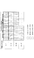
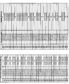
- FIG. 1 is a diagram showing an example of the association between the precoder type and the TPMI index.
- FIG. 2 is a diagram showing an example of a UE configuration assumed by UE capabilities 1-3 related to full power transmission.
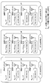
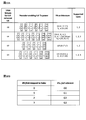
- 3A and 3B are diagrams showing an example of a TPMI group.
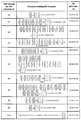
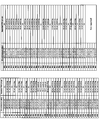
- FIG. 4 is a diagram showing an example of a precoder and PA configuration capable of full power transmission corresponding to the group reported in the first embodiment.
- FIG. 5 is a diagram showing an example of a precoder and PA configuration capable of full power transmission corresponding to the group reported in the first embodiment.
- FIGS. 6A and 6B are diagrams showing an example of a TPMI group that does not correspond to PA configurations [20 17 17 17] and [17 17 17 17] and considers antenna port switching between arbitrary ports.
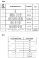
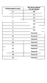
- FIG. 7 is a diagram showing an example of the correspondence between the PA configuration and the group of FIG. 6A.
- 8A and 8B are diagrams showing an example of a TPMI group corresponding to PA configurations [20 17 17 17] and [17 17 17 17 17] and considering antenna port switching between arbitrary ports.
- FIG. 9 is a diagram showing an example of the correspondence between the PA configuration and the group of FIG. 8A.
- FIG. 10A and 10B are diagrams showing an example of a TPMI group that does not correspond to the PA configuration [23 17 17 17] and considers antenna port switching between arbitrary ports.
- FIG. 11 is a diagram showing an example of the correspondence between the PA configuration and the group of FIG. 10A.
- FIG. 12 is a diagram showing an example of a TPMI group and a corresponding full-power transmittable precoder in the second embodiment.
- FIG. 13 is a diagram showing an example of TPMI group capability information showing the TPMI group of FIG.
- FIG. 14 is a diagram showing an example of a TPMI group and a corresponding full-power transmittable precoder in the second embodiment.
- FIG. 15 is a diagram showing an example of TPMI group capability information showing the TPMI group of FIG.
- FIG. 16 is a diagram showing an example of the correspondence between the PA configuration and the group of FIG. 14.
- FIG. 17 is a diagram showing an example of a TPMI group and a corresponding full-power transmittable precoder in the second embodiment.
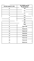
- FIG. 18 is a diagram showing an example of TPMI group capability information showing the TPMI group of FIG.
- FIG. 19 is a diagram showing an example of the correspondence between the PA configuration and the group of FIG.
- FIG. 20 is a diagram showing an example of a TPMI group and a corresponding precoder capable of full power transmission in a modified example of the second embodiment.
- FIG. 21 is a diagram showing an example of TPMI group capability information showing the TPMI group of FIG. 20.
- FIG. 22 is a diagram showing an example of a schematic configuration of a wireless communication system according to an embodiment.
- FIG. 23 is a diagram showing an example of the configuration of the base station according to the embodiment.
- FIG. 24 is a diagram showing an example of the configuration of the user terminal according to the embodiment.
- FIG. 25 is a diagram showing an example of the hardware configuration of the base station and the user terminal according to the embodiment.
- the NR considers that the UE supports at least one of codebook (Codebook (CB)) -based transmission and non-codebook (Non-Codebook (NCB)) -based transmission.
- codebook Codebook
- NCB Non-Codebook
- the UE uses at least a reference signal for measurement (Sounding Reference Signal (SRS)) and a resource index (SRS Resource Index (SRI)), and at least one of the CB-based and NCB-based uplink shared channels (PUSCH). )) It is being considered to determine the precoder (precoding matrix) for transmission.
- SRS Sounding Reference Signal
- SRI SRS Resource Index
- PUSCH CB-based and NCB-based uplink shared channels
- the UE determines a precoder for PUSCH transmission based on SRI, a transmission rank index (Transmitted Rank Indicator (TRI)), a transmission precoding matrix index (Transmitted Precoding Matrix Indicator (TPMI)), and the like. You may.
- the UE may determine a precoder for PUSCH transmission based on SRI.
- SRI, TRI, TPMI, etc. may be notified to the UE using downlink control information (DCI).
- DCI downlink control information
- SRI may be specified by the SRS Resource Indicator field (SRI field) of DCI, or by the parameter "srs-ResourceIndicator” included in the RRC information element "Configured Grant Config" of the configured grant PUSCH (configured grant PUSCH). You may.
- the TRI and TPMI may be specified by the DCI precoding information and the number of layers field ("Precoding information and number of layers" field).
- the UE may report UE capability information regarding the precoder type, and the precoder type based on the UE capability information may be set from the base station by higher layer signaling.
- the UE capability information may be precoder type information (which may be represented by the RRC parameter "pusch-TransCoherence") used by the UE in PUSCH transmission.
- the upper layer signaling may be, for example, any one of Radio Resource Control (RRC) signaling, Medium Access Control (MAC) signaling, broadcast information, or a combination thereof.
- RRC Radio Resource Control
- MAC Medium Access Control
- MAC CE MAC Control Element
- PDU MAC Protocol Data Unit
- the broadcast information may be, for example, a master information block (Master Information Block (MIB)), a system information block (System Information Block (SIB)), or the like.
- MIB Master Information Block
- SIB System Information Block
- the UE is based on the precoder type information (which may be represented by the RRC parameter "codebookSubset") contained in the PUSCH setting information (the "PUSCH-Config" information element of RRC signaling) notified by the upper layer signaling.
- the precoder used for PUSCH transmission may be determined.
- the UE may be configured by the codebookSubset with a subset of the PMI specified by the TPMI.
- the precoder type is either one of full coherent (full coherent, fully coherent, coherent), partial coherent and non-coherent (non-coherent, non-coherent), or a combination thereof (at least two combinations thereof). For example, it may be specified by parameters such as "fullyAndPartialAndNonCoherent” and "partialAndNonCoherent”).
- Full coherent may mean that all antenna ports used for transmission are synchronized (may be expressed as being able to match phase, applying the same precoder, etc.). Partial coherent may mean that some of the antenna ports used for transmission are synchronized, but some of the ports are out of sync with other ports. Non-coherent may mean that each antenna port used for transmission cannot be synchronized.
- UEs that support fully coherent precoder types may be assumed to support partially coherent and non-coherent precoder types.
- a UE that supports a partially coherent precoder type may be expected to support a non-coherent precoder type.
- the precoder type may be read as coherence, PUSCH transmission coherence, coherence type, coherence type, codebook type, codebook subset, codebook subset type, and the like.
- the UE is a TPMI index obtained from a DCI (eg, DCI format 0_1, and so on) that schedules UL transmissions from multiple precoders for CB-based transmissions (may be referred to as precoding matrices, codebooks, etc.).
- the precoding matrix corresponding to may be determined.
- FIG. 1 is a diagram showing an example of the association between the precoder type and the TPMI index.
- FIG. 1 corresponds to a table of precoding matrix W for single layer transmission using 4 antenna ports in DFT-s-OFDM (Discrete Fourier Transform spread OFDM, transform precoding is effective).
- DFT-s-OFDM Discrete Fourier Transform spread OFDM, transform precoding is effective.
- the UE is notified of any TPMI from 0 to 27 for single layer transmission. Further, when the precoder type is partialAndNonCoherent, the UE is set to any TPMI from 0 to 11 for single layer transmission. If the precoder type is nonCoherent, the UE is configured with any TPMI from 0 to 3 for single layer transmission.
- FIG. 1 shows Rel. It is a table specified in 15 NR.
- Rel. 15 when the UE uses multiple ports for codebook-based transmission, if some codebooks are used, the transmission power will be smaller than in the case of a single port (full power transmission). It may not be possible).
- a precoding matrix in which only one component in each column is not 0 may be called a non-coherent codebook.
- a precoding matrix in which the components of each column are not zero by a predetermined number (but not all) may be referred to as a partial coherent codebook.
- a precoding matrix in which the components of each column are not all zeros may be referred to as a complete coherent codebook.
- the non-coherent codebook and the partial coherent codebook may be referred to as an antenna selection precoder.
- a fully coherent codebook may be referred to as a non-antenna selection precoder.
- codebooks precoding matrix
- RRC parameter "codebookSubset” "partialAndNonCoherent”
- UE capability for full power transmission Even when using a codebook, it is preferable to properly perform full power UL transmission. Therefore, in NR, UE capability related to codebook-based full power UL transmission using a plurality of power amplifiers (Power Amplifiers (PAs)) is being studied.
- PAs Power Amplifiers
- UE capabilities 1-3 have been proposed: -UE capability 1: Supports (or has) a PA (full rated PA) that can output the maximum rated power in each transmission chain (Tx chain).
- -UE capability 2 None of the transmit chains support fully rated PA
- UE capability 3 A subset of transmit chains supports fully rated PA.
- a UE having at least one of the UE capabilities 1-3 may mean that it supports the full power of UL transmission.
- the UE may report capability information indicating that it supports the UL full power transmission capability to the network (for example, a base station).
- the UE may be configured from the network to support full power transmission.
- the UE capacity 1/2/3 may be read as a UE capacity 1/2/3, a full power transmission type 1/2/3, a power allocation type 1/2/3, etc. for full power transmission, respectively.
- types, modes, abilities, etc. may be read interchangeably.
- 1/2/3 may be read as an arbitrary number or character set such as A / B / C.
- FIG. 2 is a diagram showing an example of a UE configuration assumed by UE capabilities 1-3 related to full power transmission.
- FIG. 2 simply shows only the PA and the transmitting antenna port (which may be read as the transmitting antenna) as the configuration of the UE.
- An example is shown in which the number of PAs and the number of transmitting antenna ports are 4 respectively, but the present invention is not limited to this.
- P indicates the UE maximum output power [dBm]
- P PA indicates the PA maximum output power [dBm].
- P may be, for example, 23 dBm for a UE of power class 3 and 26 dBm for a UE of power class 2.
- P PA ⁇ P is assumed in the present disclosure, the embodiment of the present disclosure may be applied when P PA> P.
- the configuration of UE capability 1 is expected to be costly to implement, but full power transmission is possible using one or more arbitrary antenna ports.
- the configuration of UE capability 2 includes only non-full rated PA and is expected to be inexpensively implemented. However, since full power transmission cannot be performed even if only one antenna port is used, the phase of the signal input to each PA, It is required to control the amplitude and the like.
- the UE capability 1 may be referred to as mode 0.
- the configuration of UE capability 3 is intermediate between the configuration of UE capability 1 and the configuration of UE capability 2.
- Antenna ports capable of full-power transmission (transmitting antennas # 0 and # 2 in this example) and antenna ports not capable of full-power transmission (transmitting antennas # 1 and # 3 in this example) are mixed.
- a UE supporting UE capability 2 or 3 is set to at least one of two modes (modes 1 and 2) for the operation of full power transmission.
- Modes 1 and 2 may be referred to as operation modes 1 and 2, respectively.
- mode 1 is a mode in which the UE is set so that one or more SRS resources included in one SRS resource set whose usage is "codebook" have the same number of SRS ports (the mode 1). For example, it may be called the first full power transmission mode).
- the UE operating in mode 1 may transmit at full power using all antenna ports.
- the UE operating in mode 1 may be configured from the network to use a subset of TPMIs that combine ports within one layer to achieve full power transmission.
- a new codebook subset may be introduced only for rank values that include the TPMI precoder corresponding to "fullyAndPartialAndNonCoherent" defined in NR and cannot be used for full power transmission.
- mode 2 is a mode in which the UE is set so that one or more SRS resources contained in one SRS resource set whose usage is "codebook" have different numbers of SRS ports (eg,). , It may be called a second full power transmission mode).
- the UE operating in mode 2 may perform full power transmission using some antenna ports instead of all antenna ports.
- the UE operating in mode 2 may transmit PUSCH and SRS in the same way regardless of whether antenna virtualization is used or not.
- the mode 2 UE may be notified of a set of TPMIs to achieve full power transmission to support more than one SRS resource.
- 2 or 3 SRS resources may be set for one SRS resource set (up to 2 in Rel.15 NR).
- Mode 1 has the advantage that the required SRI field size can be smaller than that of mode 2 (full power transmission is possible with 1 SRS resource).
- Mode 2 has the advantage that single port transmission and multiport transmission can be dynamically switched by DCI compared to mode 1. Further, since full power transmission can be performed with some antenna ports, for example, full power transmission can be performed using only an antenna having a fully rated PA, or full power transmission can be performed using only a coherent antenna.
- the UE may determine the mode used for PUSCH transmission based on higher layer signaling (eg, RRC signaling), physical layer signaling (eg, DCI), or a combination thereof.
- the UE may set or indicate the mode of PUSCH transmission by UL full power transmission mode information (ULFPTxModes) in the upper layer parameters (eg, PUSCH configuration information (PUSCH-Config information element)).
- the UE can report UE capability information indicating that it supports mode 1, UE capability information indicating that it supports mode 2, and full power transmission in relation to mode 2. It is being considered to report UE capability information (eg, may be referred to as TPMI group capability information) regarding a TPMI set (which may be referred to as TPMI group).
- UE capability information eg, may be referred to as TPMI group capability information
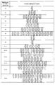
- FIGS. 3A and 3B are diagrams showing an example of the TPMI group.
- FIG. 3A shows a precoding matrix (precoder) of each rank corresponding to the TPMI group when the number of transmitting antenna ports is 4.
- a precoder capable of full power transmission for a rank corresponds to one or more precoders in a range separated by at least one of a colon ":" and a semicolon ";”.
- a precoder capable of full power transmission for a certain rank has a plurality of precoders enclosed in " ⁇ "
- any of the plurality of precoders can perform full power transmission for the rank.
- the number of columns in each matrix may represent the number of layers.
- FIG. 3B shows an example of a TPMI group assumed for a UE of a 4-transmit antenna port.
- the non-coherent UE with 4 transmit antenna ports may correspond to any of G0-G3.
- 4 The partially coherent UE of the transmitting antenna port may correspond to any of G0-G6.
- the UE may scale (eg, multiply, divide) the linear value of the PUSCH transmit power, which is determined based on path loss or the like, by a factor s.
- the coefficient may be referred to as a power scaling coefficient.
- the non-zero PUSCH antenna port may mean an antenna port having non-zero PUSCH transmission power, and among the antenna ports whose transmission is indicated by the precoding matrix (codebook subset), the value is not zero (the value is not zero).
- 1, j) may mean an antenna port.
- the number of SRS ports is the number of SRS ports related to the SRS resource if only one SRS resource is set in the SRS resource set whose purpose is the codebook, and the use is the codebook.
- more than one SRS resource is set in the SRS resource set, it may correspond to the number of SRS ports of the SRS resource indicated by SRI.
- the UE may divide the linear value of the PUSCH transmission power scaled using the coefficient s evenly across the non-zero PUSCH antenna port.
- the UE may apply the determined (or assumed) coefficient s to the precoding matrix to transmit the PUSCH at full power.
- the UE may transmit the PUSCH at full power using a matrix obtained by multiplying the matrix portion of the precoding matrix by the above s (or ⁇ s).
- mode 2 requires the UE to report a TPMI group that supports UL full power transmission.
- the question of what kind of TPMI group the UE should report has not been investigated yet.
- the TPMI group currently being considered is for non-coherent UEs, and when reporting TPMI group capability information for a fully coherent UE, it is considered what kind of TPMI group should be reported. It has not been.
- the UE cannot properly perform full power transmission. If full power transmission is not possible, coverage may decrease and the increase in communication throughput may be suppressed.
- the present inventors analyzed the UE capability and the corresponding PA configuration, and came up with a set of groups suitable for reporting.
- the UE can perform UL MIMO (Multi Input Multi Output) transmission at full power, and can maintain the same cell coverage as a single antenna.
- UL MIMO Multi Input Multi Output
- spatial diversity gain can be obtained, and throughput improvement can be expected.
- full power may be read as “power boosting”, “maximum power”, “extended power”, “power higher than Rel.15 UE” and the like.
- having coherent abilities may be read as being mutually read as reporting the ability, setting the coherent, and so on.
- non-coherent UE the partial coherent UE, and the fully coherent UE may be read as a UE having a non-coherent ability, a UE having a partial coherent ability, and a UE having a complete coherent ability, respectively.
- non-coherent UE partial coherent UE
- complete coherent UE refer to the codebook subsets of "nonCoherent”, “partialAndNonCoherent”, and “fullyAndPartialAndNonCoherent”, respectively. It may mean a UE set in a higher layer. In the present disclosure, the codebook subset and the codebook may be read as each other.
- the non-coherent UE, the partial coherent UE, and the fully coherent UE may mean a UE that can be transmitted using the non-coherent codebook, the partial coherent codebook, and the fully coherent codebook, respectively.
- mode 1 or 2 is described as being related to the SRS resource set of the codebook, but is not limited thereto. Modes 1 or 2 of each embodiment may be read, for example, in modes 1 or 2 for SRS resource sets whose use is non-codebook.
- matrix of TPMI X
- TPMI X
- the non-coherent codebook and the partial coherent codebook may be referred to as an antenna selection precoder.
- a fully coherent codebook may be referred to as a non-antenna selection precoder.
- the TPMI corresponding to the antenna selection precoder may be referred to as an antenna selection TPMI.
- the TPMI corresponding to the non-antenna selection precoder may be referred to as a non-antenna selection TPMI.
- TPMI precoder "TPMI group,” “one or more TPMI,” “TPMI group that enables full power,” “TPMI group that supports full power,” and the like may be read interchangeably. ..
- the "UE” in the following embodiment assumes a UE that supports mode 2, but is not limited to this. Further, although an example of four transmitting antenna ports is shown in the following embodiment, the number of transmitting antenna ports may be read as a different number.
- RRC parameter "codebookSubset” “nonCoherent” or “partialAndNonCoherent” or “fullyAndPartialAndNonCoherent”. ”
- the PUSCH setting information includes a parameter (“ULFPTx”) indicating full power transmission
- the UE scales the linear value of the PUSCH transmission power determined based on the path loss or the like by the power scaling coefficient s. You may.
- a table that defines a separate TPMI group for mode 2 operation may be used for each non-coherent UE, partial coherent UE, and full coherent UE.
- the definition of TPMI group may differ according to coherent ability.
- a UE that supports mode 2 and has 4 transmit antenna ports (4Tx) may select the TPMI group to report from the table corresponding to the coherent capability.
- the number of bits used to report the TPMI group may depend on the coherent capacity.
- the number of bits used to report the TPMI group does not have to depend on the coherent ability.
- These values of X may be determined from the codebook subset contained in the PUSCH configuration information, may be explicitly or implicitly set by RRC signaling, or may be predetermined by specifications.
- the TPMI group for a fully coherent UE corresponds to a group defined differently from the TPMI group (G0-G6 in FIG. 3A) that has already been agreed to be introduced for a non-coherent UE. ..
- the TPMI group (G0-G6 in FIG. 3A) that has already been agreed to be introduced is limited to coherent port pairs of partially coherent UEs (eg, pairs of ports 0 and 2 and pairs of ports 1 and 3). Therefore, it also includes definitions that are not suitable for fully coherent UEs. For example, a fully coherent UE having 4 transmit antenna ports can switch any antenna port and use it for full power transmission because all of ports 0-3 are coherent. Note that ports 0, 1, 2, and 3 are merely port numbers for convenience, and may correspond to arbitrary port numbers.
- the TPMI groups G0-G6 for the fully coherent UE may be different from the G0-G6 in FIG. 3A (note that they may be the same).
- the coherent port pair may be read as a coherent subset, a coherent port set, and the like.
- Ports included in a coherent port pair may be assumed to be coherent to each other.
- a port contained in one coherent port pair may be assumed to be less coherent than a port contained in another coherent port pair.
- a fully coherent UE may assume that any port pair is a coherent port pair.
- FIG. 4 is a diagram showing an example of a precoder and PA configuration capable of full power transmission corresponding to the group reported in the first embodiment.
- FIG. 4 an example of the configuration in which each PA corresponding to the four transmission ports can take three output powers (23 dBm, 20 dBm, 17 dBm) is shown.
- the column "Precoder enavling full Tx power" in FIG. 4 shows an example of a precoder capable of full power transmission.
- TPMI which indicates a coherent codebook.
- the full coherent TPMI that the UE can transmit at full power is not limited to this.
- G10 indicates that full power transmission is possible only with the non-antenna selection precoder (full power transmission is not possible with the antenna selection precoder).
- the column of "PA architecture" in FIG. 4 shows the PA configuration.
- the PA configuration may indicate the output voltage of the PA corresponding to ports 0, 1, 2, and 3 from the left (or in reverse order). Note that these ports may be arbitrarily replaced.
- the UE may assume that the port corresponding to "23" is capable of full power transmission by itself.
- the UE may assume that full power transmission is possible by using two or more ports corresponding to "20”.
- the UE may assume that full power transmission is possible by using four or more ports corresponding to "17”.
- the UE may select at least one group from G0-G10 in the table of FIG. 4 for a fully coherent UE and transmit TPMI group capability information indicating the selected group to the network.
- the full coherent UE does not report the TPMI group capability information, it may be assumed that UL full power transmission based on a specific TPMI group can be performed.
- a full coherent UE that does not report TPMI group capability information may perform full power transmissions based on G10 (ie, full power transmissions according to TPMI with only non-zero PUSCH ports using a full coherent codebook). In this case, the fully coherent UE does not have to explicitly report G10 as TPMI group capability information.
- FIG. 5 is a diagram showing an example of a precoder and PA configuration capable of full power transmission corresponding to the group reported in the first embodiment.
- FIG. 5 differs from FIG. 4 in that the table does not include the fully coherent TPMI. Since G0-G10 in FIG. 4 all support full power transmission of full coherent TPMI, FIG. 5 corresponds to a table omitting this.
- the PA configuration of FIG. 5 is the same as that of FIG.
- the UE may select at least one group from G0-G10 in the table of FIG. 5 for a fully coherent UE and transmit TPMI group capability information indicating the selected group to the network. Further, if the full coherent UE does not report the TPMI group capability information, it may be assumed that UL full power transmission based on the specific TPMI group can be performed as described above.
- One group supports multiple PA configurations
- An example in which one group may correspond to a plurality of PA configurations will be described with reference to FIGS. 6 to 11. Considering that a fully coherent UE can switch any antenna port, we determine how many powers each PA can output rather than how the PAs are lined up in determining the TPMI group. Focusing on this, we found the composition of these groups.
- FIGS. 6A and 6B are diagrams showing an example of a TPMI group that does not correspond to PA configurations [20 17 17 17] and [17 17 17 17] and considers antenna port switching between arbitrary ports.
- FIG. 6A is a diagram showing an example of a TPMI group and a corresponding precoder and PA configuration capable of full power transmission. As in FIG. 5, the full coherent TPMI is not included in the table of FIG. 6A because each group supports full power transmission of the fully coherent TPMI.
- the "Supported ranks" column in FIG. 6A shows the ranks supported by the PA configuration corresponding to the TPMI group.
- the maximum rank for the PA configuration may be determined based on the UE capability (TPMI group).
- FIG. 6B is a diagram showing an example of TPMI group ability information showing the TPMI group of FIG. 6A.
- each bit field value 0-4 corresponds to one group (G0-G4).
- reservation “Reserved”) is specified, but the present invention is not limited to this.
- FIG. 7 is a diagram showing an example of the correspondence between the PA configuration and the group of FIG. 6A. This example shows an example of a configuration in which each PA corresponding to four transmission ports can take three output powers (23 dBm, 20 dBm, 17 dBm) in consideration of all UE capabilities 1-3.
- the leftmost column is a convenient index for associating PA configurations and TPMI groups.
- Index # 1- # 64 corresponds to the PA configuration of UE capability 3 including one or more and three or less of 23 dBm.
- Indexes # 65- # 75 correspond to the PA configuration of UE capability 2 not including 23 dBm.
- Index # 76 corresponds to the PA configuration of UE capability 1 including only 23 dBm.
- Indexes # 77- # 81 correspond to PA configurations that cannot be fully powered by non-coherent or partially coherent precoders.
- Mode 2 which is required to report the TPMI group, corresponds to UE capability 2 or 3. Therefore, it may be assumed that the UE does not need to report the TPMI group representing the PA configuration corresponding to indexes # 77- # 81 in FIG.
- the column of "PA architecture” in FIG. 7 shows the PA configuration.
- the column of "Reported TPMI groups” in FIG. 7 shows a group that can represent a PA configuration.
- the PA configuration of "GX w / switching” means that it is represented by switching an arbitrary port from the PA configuration of the group GX (X is an integer).
- the PA configuration [17 23 17 17] of # 16 can be realized by switching the ports # 0 and # 1 of the PA configuration of the group G0 ([23 17 17 17] of # 15).
- G0-G4 can be used to report all required PA configurations.
- FIGS. 8A and 8B are diagrams showing an example of a TPMI group corresponding to PA configurations [20 17 17 17] and [17 17 17 17] and considering antenna port switching between arbitrary ports.
- FIG. 8A differs from FIG. 6A in that group G5 is defined, which indicates that full power transmission is possible only with the non-antenna selection precoder (full power transmission is not possible with the antenna selection precoder).
- FIG. 9 is a diagram showing an example of the correspondence between the PA configuration and the group of FIG. 8A.
- the index # 77- # 81 is represented by G5 (or G5 w / switching), which is different from FIG. 7.
- G0-G5 can be used to report all required PA configurations.
- the network sets an SRS resource set (for example, an SRS resource set whose purpose is a codebook) containing two or more SRS resources for the UE of G5.
- the UE can use, for example, up to four PUSCH beams based on the DCI instruction, so that flexible control is possible.
- FIGS. 10A and 10B are diagrams showing an example of a TPMI group that does not correspond to the PA configuration [23 17 17 17] and considers antenna port switching between arbitrary ports.
- FIG. 10A corresponds to a table in which G0 in FIG. 6A is deleted and G1-G4 in FIG. 6A is defined as G0-G3.
- the four groups of FIG. 10A can be represented by two bits, as shown in FIG. 10B.
- the number of TPMI groups (or groups of groups) to be reported is reduced, and efficient capacity information can be used.
- the set of groups in FIG. 10A does not include the group (G0 in FIG. 6A) indicating that it supports full power transmission of only one port according to the non-coherent TPMI but does not support full power transmission using multiple ports. .. That is, in the set of groups of FIG. 10A, each group is shown to support full power transmission using multiple ports.
- FIG. 11 is a diagram showing an example of the correspondence between the PA configuration and the group of FIG. 10A. It differs from FIG. 7 in that indexes # 15- # 18 are not reported and G1-G4 is changed to G0-G3.
- TPMI 0-3 in FIG. 1
- an arbitrary port is used (antenna port virtualization is applied). Then) UL full power PUSCH transmission may be performed.
- a full coherent UE that does not report TPMI group capability information may perform full power transmission using a plurality of antenna ports (that is, full power transmission according to TPMI corresponding to a partial or full coherent codebook).
- the full coherent UE can determine and report detailed PA configuration information using the TPMI group ability information.
- the TPMI group for a fully coherent UE includes a TPMI group (G0-G6 in FIG. 3A) that has already been agreed to be introduced for a non-coherent UE.
- the TPMI group and the group group described in the second embodiment may be used as a TPMI group for a non / partially coherent UE.
- FIG. 12 is a diagram showing an example of a TPMI group and a corresponding precoder capable of full power transmission in the second embodiment.
- the TPMI group of FIG. 12 is the same as the existing G0-G6 of FIG. 3A.
- the UE may select at least one group from G0-G6 in the table of FIG. 12 for the fully coherent UE and transmit TPMI group capability information indicating the selected group to the network.
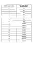
- FIG. 13 is a diagram showing an example of TPMI group ability information showing the TPMI group of FIG.
- the value of the 4-bit TPMI group capability information (“Bit field mapped to index” in the figure) that can be reported by the partial / fully coherent UE having a 4-transmit antenna port (4Tx), the corresponding group, and the corresponding group. Correspondence is shown.
- reservation (Reserved) is specified.
- the correspondence between the bit field value and the group is not limited to this. The same applies to the subsequent drawings relating to bit fields.
- FIG. 14 is a diagram showing an example of a TPMI group and a corresponding precoder capable of full power transmission in the second embodiment.
- the TPMI group of FIG. 14 can show combinations of these in addition to the existing G0-G6 of FIG. 3A.
- G0-G6 may each show the following PA configurations.
- ⁇ G0 Port 0 is 23 dBm
- ⁇ G1 Ports 0 and 2 are 23 dBm
- ⁇ G2 Ports 0, 1 and 2 are 23 dBm
- ⁇ G3 Ports 0, 1 and 2 are 20 dBm
- ⁇ G4 Ports 0 and 2 are 20 dBm
- ⁇ G5 Ports 0, 1 and 2 are 20 dBm
- -G6 Ports 0, 1, 2, 3 are 20 dBm.
- Each combination of a plurality of groups may show the following PA composition.
- the UE may select at least one of the groups or groups of groups in the table of FIG. 14 for fully coherent UEs and transmit TPMI group capability information indicating the selected groups or groups of groups to the network.
- FIG. 16 is a diagram showing an example of the correspondence between the PA configuration and the group of FIG. 14. Since this example has the same table as in FIG. 7, duplicate explanations will not be repeated.
- the PA configuration of "GX and GY” in the "Reported TPMI groups” column of FIG. 16 corresponds to ⁇ GX, GY ⁇ of FIG. Further, the PA configuration of "GX and GY w / switching" means that it is represented by switching an arbitrary port from the PA configuration of the group GX and GY (where X and Y are integers).
- the TPMI group in FIG. 14 does not correspond to the PA configuration [23, 23, 23, 23] of index # 76 as shown in FIG. 16, but since this PA configuration is supported in mode 0 in the first place, it is reported in mode 2. There is no need to.
- the TPMI group of FIG. 14 is suitable when antenna port switching is possible between arbitrary port pairs (for example, port 0 can be switched to any of ports 0, 1, 2 and 3).
- port 0 can be switched to any of ports 0, 1, 2 and 3.
- a configuration in which antenna port switching is performed only between some port pairs can be considered.
- the UE can switch port 0 only to ports 0 and 2 that make up the same coherent port pair of the partial coherent UE, not ports 1 and 3 that belong to different coherent port pairs of the partial coherent UE. ..
- FIG. 17 will explain an example of a set of TPMI groups suitable when antenna port switching is not possible between arbitrary port pairs.
- FIG. 17 is a diagram showing an example of a TPMI group and a corresponding full-power transmittable precoder in the second embodiment.
- the TPMI group of FIG. 17 differs from FIG. 12 in that G7 and G8 are added.
- G7-G8 may each show the following PA configurations.
- Port 0 is 23 dBm
- Port 1 is 20 dBm
- -G8 Ports 0 and 1 are 20 dBm.
- the UE may select at least one of the groups or groups of groups in the table of FIG. 17 for fully coherent UEs and transmit TPMI group capability information indicating the selected groups or groups of groups to the network.
- FIG. 19 is a diagram showing an example of the correspondence between the PA configuration and the group of FIG. Since this example has the same table as in FIG. 7, duplicate explanations will not be repeated.
- FIG. 19 some PA configurations of FIG. 16 have been replaced by G7 or G8.
- FIG. 20 is a diagram showing an example of a TPMI group and a corresponding precoder capable of full power transmission in a modified example of the second embodiment.
- the TPMI group of FIG. 20 corresponds to the TPMI group of FIG. 12 plus G10.
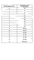
- a bit field indicating G10 may be introduced in the correspondence of the TPMI group ability information in FIGS. 15 and 18.
- the full coherent UE can determine and report detailed PA configuration information using the TPMI group ability information.
- UL transmission using the antenna port has been described assuming PUSCH, but at least one full power transmission of other signals and channels in addition to or in place of PUSCH. It may be controlled.
- the antenna port in each of the above-described embodiments is a PUSCH (and a demodulation reference signal for PUSCH (DeModulation Reference Signal (DMRS)), a phase tracking reference signal (Phase Tracking Reference Signal (PTRS))), and an uplink control channel ( It may be at least one antenna port such as Physical Uplink Control Channel (PUCCH), Random Access Channel (PRACH), SRS, etc., and full power transmission to at least one of these signals and channels. May be applied.
- DMRS DeModulation Reference Signal
- PTRS Phase Tracking Reference Signal
- the UE has been shown in the first and second embodiments depending on whether it has the ability to support antenna port switching between any port pair (or whether it reports information about that capability). It may be determined which TPMI group capability information to use (eg, first embodiment if reported).
- the first embodiment and the second embodiment depend on whether or not the UE has the ability to support antenna port switching between the port pairs contained in a particular coherent port pair (or whether or not to report information on the ability). It may be determined which TPMI group capability information of the embodiment is used (eg, the second embodiment if reported).
- the numbers such as “23”, “20”, and “17” in this disclosure are values with the output power of the power class 3 UE in mind, and are not limited to these.
- “23” may be read as the first power value (for example, the maximum output power of a UE of a certain power class), and “20” may be read as the second power value (for example, the maximum output power-3 [for example. It may be read as the value of dBm].
- “17” may be read as a third power value (for example, a second power value-3 [dBm] value).
- wireless communication system Wireless communication system
- communication is performed using any one of the wireless communication methods according to each of the above-described embodiments of the present disclosure or a combination thereof.
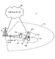
- FIG. 22 is a diagram showing an example of a schematic configuration of a wireless communication system according to an embodiment.
- the wireless communication system 1 may be a system that realizes communication using Long Term Evolution (LTE), 5th generation mobile communication system New Radio (5G NR), etc. specified by Third Generation Partnership Project (3GPP). ..
- the wireless communication system 1 may support dual connectivity (Multi-RAT Dual Connectivity (MR-DC)) between a plurality of Radio Access Technologies (RATs).
- MR-DC is a dual connectivity (E-UTRA-NR Dual Connectivity (EN-DC)) between LTE (Evolved Universal Terrestrial Radio Access (E-UTRA)) and NR, and a dual connectivity (NR-E) between NR and LTE.
- E-UTRA-NR Dual Connectivity Evolved Universal Terrestrial Radio Access (E-UTRA)
- NR-E dual connectivity
- NE-DC -UTRA Dual Connectivity
- the LTE (E-UTRA) base station (eNB) is the master node (Master Node (MN)), and the NR base station (gNB) is the secondary node (Secondary Node (SN)).
- the base station (gNB) of NR is MN
- the base station (eNB) of LTE (E-UTRA) is SN.
- the wireless communication system 1 has dual connectivity between a plurality of base stations in the same RAT (for example, dual connectivity (NR-NR Dual Connectivity (NN-DC)) in which both MN and SN are NR base stations (gNB). )) May be supported.
- a plurality of base stations in the same RAT for example, dual connectivity (NR-NR Dual Connectivity (NN-DC)) in which both MN and SN are NR base stations (gNB). )
- NR-NR Dual Connectivity NR-DC
- gNB NR base stations
- the wireless communication system 1 includes a base station 11 that forms a macrocell C1 having a relatively wide coverage, and a base station 12 (12a-12c) that is arranged in the macrocell C1 and forms a small cell C2 that is narrower than the macrocell C1. You may prepare.
- the user terminal 20 may be located in at least one cell. The arrangement, number, and the like of each cell and the user terminal 20 are not limited to the mode shown in the figure.
- the base stations 11 and 12 are not distinguished, they are collectively referred to as the base station 10.
- the user terminal 20 may be connected to at least one of a plurality of base stations 10.
- the user terminal 20 may use at least one of carrier aggregation (Carrier Aggregation (CA)) and dual connectivity (DC) using a plurality of component carriers (Component Carrier (CC)).
- CA Carrier Aggregation
- DC dual connectivity
- CC Component Carrier
- Each CC may be included in at least one of a first frequency band (Frequency Range 1 (FR1)) and a second frequency band (Frequency Range 2 (FR2)).
- the macrocell C1 may be included in FR1 and the small cell C2 may be included in FR2.
- FR1 may be in a frequency band of 6 GHz or less (sub 6 GHz (sub-6 GHz)), and FR 2 may be in a frequency band higher than 24 GHz (above-24 GHz).
- the frequency bands and definitions of FR1 and FR2 are not limited to these, and for example, FR1 may correspond to a frequency band higher than FR2.
- the user terminal 20 may perform communication using at least one of Time Division Duplex (TDD) and Frequency Division Duplex (FDD) in each CC.
- TDD Time Division Duplex
- FDD Frequency Division Duplex
- the plurality of base stations 10 may be connected by wire (for example, optical fiber compliant with Common Public Radio Interface (CPRI), X2 interface, etc.) or wirelessly (for example, NR communication).
- wire for example, optical fiber compliant with Common Public Radio Interface (CPRI), X2 interface, etc.
- NR communication for example, when NR communication is used as a backhaul between base stations 11 and 12, the base station 11 corresponding to the higher-level station is an Integrated Access Backhaul (IAB) donor, and the base station 12 corresponding to a relay station (relay) is IAB. It may be called a node.
- IAB Integrated Access Backhaul
- relay station relay station
- the base station 10 may be connected to the core network 30 via another base station 10 or directly.
- the core network 30 may include at least one such as Evolved Packet Core (EPC), 5G Core Network (5GCN), and Next Generation Core (NGC).
- EPC Evolved Packet Core
- 5GCN 5G Core Network
- NGC Next Generation Core
- the user terminal 20 may be a terminal that supports at least one of communication methods such as LTE, LTE-A, and 5G.
- a wireless access method based on Orthogonal Frequency Division Multiplexing may be used.
- OFDM Orthogonal Frequency Division Multiplexing
- DL Downlink
- UL Uplink
- CP-OFDM Cyclic Prefix OFDM
- DFT-s-OFDM Discrete Fourier Transform Spread OFDM
- OFDMA Orthogonal Frequency Division Multiple. Access
- SC-FDMA Single Carrier Frequency Division Multiple Access
- the wireless access method may be called a waveform.
- another wireless access system for example, another single carrier transmission system, another multi-carrier transmission system
- the UL and DL wireless access systems may be used as the UL and DL wireless access systems.
- a downlink shared channel Physical Downlink Shared Channel (PDSCH)
- a broadcast channel Physical Broadcast Channel (PBCH)
- a downlink control channel Physical Downlink Control
- PDSCH Physical Downlink Control
- the uplink shared channel Physical Uplink Shared Channel (PUSCH)
- the uplink control channel Physical Uplink Control Channel (PUCCH)
- the random access channel shared by each user terminal 20 are used.
- Physical Random Access Channel (PRACH) Physical Random Access Channel or the like may be used.
- User data, upper layer control information, System Information Block (SIB), etc. are transmitted by PDSCH.
- User data, upper layer control information, and the like may be transmitted by the PUSCH.
- the Master Information Block (MIB) may be transmitted by the PBCH.
- Lower layer control information may be transmitted by PDCCH.
- the lower layer control information may include, for example, downlink control information (Downlink Control Information (DCI)) including scheduling information of at least one of PDSCH and PUSCH.
- DCI Downlink Control Information
- the DCI that schedules PDSCH may be called DL assignment, DL DCI, or the like, and the DCI that schedules PUSCH may be called UL grant, UL DCI, or the like.
- the PDSCH may be read as DL data, and the PUSCH may be read as UL data.
- a control resource set (COntrol REsource SET (CORESET)) and a search space (search space) may be used for PDCCH detection.
- CORESET corresponds to a resource for searching DCI.
- the search space corresponds to the search area and search method of PDCCH candidates (PDCCH candidates).
- One CORESET may be associated with one or more search spaces. The UE may monitor the CORESET associated with a search space based on the search space settings.
- One search space may correspond to PDCCH candidates corresponding to one or more aggregation levels.
- One or more search spaces may be referred to as a search space set.
- the "search space”, “search space set”, “search space setting”, “search space set setting”, “CORESET”, “CORESET setting”, etc. of the present disclosure may be read as each other.
- channel state information (Channel State Information (CSI)
- delivery confirmation information for example, it may be called Hybrid Automatic Repeat reQuest ACKnowledgement (HARQ-ACK), ACK / NACK, etc.
- scheduling request for example.
- Uplink Control Information (UCI) including at least one of SR) may be transmitted.
- the PRACH may transmit a random access preamble to establish a connection with the cell.
- downlinks, uplinks, etc. may be expressed without “links”. Further, it may be expressed without adding "Physical" to the beginning of various channels.
- a synchronization signal (Synchronization Signal (SS)), a downlink reference signal (Downlink Reference Signal (DL-RS)), and the like may be transmitted.
- the DL-RS includes a cell-specific reference signal (Cell-specific Reference Signal (CRS)), a channel state information reference signal (Channel State Information Reference Signal (CSI-RS)), and a demodulation reference signal (DeModulation).
- CRS Cell-specific Reference Signal
- CSI-RS Channel State Information Reference Signal
- DeModulation Demodulation reference signal
- Reference Signal (DMRS)), positioning reference signal (Positioning Reference Signal (PRS)), phase tracking reference signal (Phase Tracking Reference Signal (PTRS)), and the like may be transmitted.
- PRS Positioning Reference Signal
- PTRS Phase Tracking Reference Signal
- the synchronization signal may be, for example, at least one of a primary synchronization signal (Primary Synchronization Signal (PSS)) and a secondary synchronization signal (Secondary Synchronization Signal (SSS)).
- PSS Primary Synchronization Signal
- SSS Secondary Synchronization Signal
- the signal block including SS (PSS, SSS) and PBCH (and DMRS for PBCH) may be referred to as SS / PBCH block, SS Block (SSB) and the like.
- SS, SSB and the like may also be called a reference signal.
- a measurement reference signal Sounding Reference Signal (SRS)
- a demodulation reference signal DMRS
- UL-RS Uplink Reference Signal
- UE-specific Reference Signal UE-specific Reference Signal
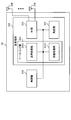
- FIG. 23 is a diagram showing an example of the configuration of the base station according to the embodiment.
- the base station 10 includes a control unit 110, a transmission / reception unit 120, a transmission / reception antenna 130, and a transmission line interface 140.
- the control unit 110, the transmission / reception unit 120, the transmission / reception antenna 130, and the transmission line interface 140 may each be provided with one or more.
- the functional block of the characteristic portion in the present embodiment is mainly shown, and it may be assumed that the base station 10 also has other functional blocks necessary for wireless communication. A part of the processing of each part described below may be omitted.
- the control unit 110 controls the entire base station 10.
- the control unit 110 can be composed of a controller, a control circuit, and the like described based on the common recognition in the technical field according to the present disclosure.
- the control unit 110 may control signal generation, scheduling (for example, resource allocation, mapping) and the like.
- the control unit 110 may control transmission / reception, measurement, and the like using the transmission / reception unit 120, the transmission / reception antenna 130, and the transmission line interface 140.
- the control unit 110 may generate data to be transmitted as a signal, control information, a sequence, and the like, and transfer the data to the transmission / reception unit 120.
- the control unit 110 may perform call processing (setting, release, etc.) of the communication channel, state management of the base station 10, management of radio resources, and the like.
- the transmission / reception unit 120 may include a baseband unit 121, a Radio Frequency (RF) unit 122, and a measurement unit 123.
- the baseband unit 121 may include a transmission processing unit 1211 and a reception processing unit 1212.
- the transmitter / receiver 120 includes a transmitter / receiver, an RF circuit, a baseband circuit, a filter, a phase shifter, a measurement circuit, a transmitter / receiver circuit, and the like, which are described based on the common recognition in the technical field according to the present disclosure. be able to.
- the transmission / reception unit 120 may be configured as an integrated transmission / reception unit, or may be composed of a transmission unit and a reception unit.
- the transmission unit may be composed of a transmission processing unit 1211 and an RF unit 122.
- the receiving unit may be composed of a receiving processing unit 1212, an RF unit 122, and a measuring unit 123.
- the transmitting / receiving antenna 130 can be composed of an antenna described based on the common recognition in the technical field according to the present disclosure, for example, an array antenna.
- the transmission / reception unit 120 may transmit the above-mentioned downlink channel, synchronization signal, downlink reference signal, and the like.
- the transmission / reception unit 120 may receive the above-mentioned uplink channel, uplink reference signal, and the like.
- the transmission / reception unit 120 may form at least one of a transmission beam and a reception beam by using digital beamforming (for example, precoding), analog beamforming (for example, phase rotation), and the like.
- digital beamforming for example, precoding
- analog beamforming for example, phase rotation
- the transmission / reception unit 120 processes, for example, Packet Data Convergence Protocol (PDCP) layer processing and Radio Link Control (RLC) layer processing (for example, RLC) for data, control information, etc. acquired from control unit 110.
- PDCP Packet Data Convergence Protocol
- RLC Radio Link Control
- MAC Medium Access Control
- HARQ retransmission control HARQ retransmission control
- the transmission / reception unit 120 performs channel coding (may include error correction coding), modulation, mapping, filtering, and discrete Fourier transform (Discrete Fourier Transform (DFT)) for the bit string to be transmitted. Processing (if necessary), inverse Fast Fourier Transform (IFFT) processing, precoding, transmission processing such as digital-analog transformation may be performed, and the baseband signal may be output.
- channel coding may include error correction coding
- modulation modulation
- mapping mapping, filtering
- DFT discrete Fourier Transform
- IFFT inverse Fast Fourier Transform
- precoding coding
- transmission processing such as digital-analog transformation
- the transmission / reception unit 120 may perform modulation, filtering, amplification, etc. on the baseband signal to the radio frequency band, and transmit the signal in the radio frequency band via the transmission / reception antenna 130. ..
- the transmission / reception unit 120 may perform amplification, filtering, demodulation to a baseband signal, or the like on the signal in the radio frequency band received by the transmission / reception antenna 130.
- the transmission / reception unit 120 (reception processing unit 1212) performs analog-digital conversion, fast Fourier transform (FFT) processing, and inverse discrete Fourier transform (IDFT) for the acquired baseband signal. )) Processing (if necessary), filtering, decoding, demodulation, decoding (may include error correction decoding), MAC layer processing, RLC layer processing, PDCP layer processing, and other reception processing are applied. User data and the like may be acquired.
- FFT fast Fourier transform
- IDFT inverse discrete Fourier transform
- the transmission / reception unit 120 may perform measurement on the received signal.
- the measurement unit 123 may perform Radio Resource Management (RRM) measurement, Channel State Information (CSI) measurement, or the like based on the received signal.
- the measuring unit 123 has received power (for example, Reference Signal Received Power (RSRP)) and reception quality (for example, Reference Signal Received Quality (RSRQ), Signal to Interference plus Noise Ratio (SINR), Signal to Noise Ratio (SNR)).
- RSRP Reference Signal Received Power
- RSSQ Reference Signal Received Quality
- SINR Signal to Noise Ratio
- Signal strength for example, Received Signal Strength Indicator (RSSI)
- propagation path information for example, CSI
- the measurement result may be output to the control unit 110.
- the transmission line interface 140 transmits / receives signals (backhaul signaling) to / from a device included in the core network 30, another base station 10, etc., and user data (user plane data) for the user terminal 20 and a control plane. Data or the like may be acquired or transmitted.
- the transmission unit and the reception unit of the base station 10 in the present disclosure may be composed of at least one of the transmission / reception unit 120, the transmission / reception antenna 130, and the transmission path interface 140.
- the transmission / reception unit 120 includes capability information indicating a supported full-power transmission mode (for example, mode 1 and mode 2) and a transmission precoding matrix index (Transmitted Precoding Matrix Indicator) that supports full-power transmission. (TPMI)) At least one of the ability information indicating the group (TPMI group ability information) may be received.
- capability information indicating a supported full-power transmission mode (for example, mode 1 and mode 2) and a transmission precoding matrix index (Transmitted Precoding Matrix Indicator) that supports full-power transmission.
- TPMI Transmission Precoding Matrix Indicator
- the control unit 110 is defined as a second TPMI group, which is defined differently from a set of first transmitted precoding matrix indicators (TPMI) groups for terminals that support a partially coherent codebook subset. It may be assumed that the user terminal 20 generates the TPMI group capability information based on the set of.
- TPMI transmitted precoding matrix indicators
- the transmission / reception unit 120 may receive the TPMI group capability information corresponding to the TPMI group that supports full power transmission, which is transmitted from the user terminal 20.
- FIG. 24 is a diagram showing an example of the configuration of the user terminal according to the embodiment.
- the user terminal 20 includes a control unit 210, a transmission / reception unit 220, and a transmission / reception antenna 230.
- the control unit 210, the transmission / reception unit 220, and the transmission / reception antenna 230 may each be provided with one or more.
- the functional block of the feature portion in the present embodiment is mainly shown, and it may be assumed that the user terminal 20 also has other functional blocks necessary for wireless communication. A part of the processing of each part described below may be omitted.
- the control unit 210 controls the entire user terminal 20.
- the control unit 210 can be composed of a controller, a control circuit, and the like described based on the common recognition in the technical field according to the present disclosure.
- the control unit 210 may control signal generation, mapping, and the like.
- the control unit 210 may control transmission / reception, measurement, and the like using the transmission / reception unit 220 and the transmission / reception antenna 230.
- the control unit 210 may generate data to be transmitted as a signal, control information, a sequence, and the like, and transfer the data to the transmission / reception unit 220.
- the transmission / reception unit 220 may include a baseband unit 221, an RF unit 222, and a measurement unit 223.
- the baseband unit 221 may include a transmission processing unit 2211 and a reception processing unit 2212.
- the transmitter / receiver 220 can be composed of a transmitter / receiver, an RF circuit, a baseband circuit, a filter, a phase shifter, a measurement circuit, a transmitter / receiver circuit, and the like, which are described based on the common recognition in the technical field according to the present disclosure.
- the transmission / reception unit 220 may be configured as an integrated transmission / reception unit, or may be composed of a transmission unit and a reception unit.
- the transmission unit may be composed of a transmission processing unit 2211 and an RF unit 222.
- the receiving unit may be composed of a receiving processing unit 2212, an RF unit 222, and a measuring unit 223.
- the transmitting / receiving antenna 230 can be composed of an antenna described based on the common recognition in the technical field according to the present disclosure, for example, an array antenna.
- the transmission / reception unit 220 may receive the above-mentioned downlink channel, synchronization signal, downlink reference signal, and the like.
- the transmission / reception unit 220 may transmit the above-mentioned uplink channel, uplink reference signal, and the like.
- the transmission / reception unit 220 may form at least one of a transmission beam and a reception beam by using digital beamforming (for example, precoding), analog beamforming (for example, phase rotation), and the like.
- digital beamforming for example, precoding
- analog beamforming for example, phase rotation
- the transmission / reception unit 220 processes, for example, PDCP layer processing, RLC layer processing (for example, RLC retransmission control), and MAC layer processing (for example, for data, control information, etc. acquired from the control unit 210). , HARQ retransmission control), etc., to generate a bit string to be transmitted.
- the transmission / reception unit 220 (transmission processing unit 2211) performs channel coding (may include error correction coding), modulation, mapping, filtering processing, DFT processing (if necessary), and IFFT processing for the bit string to be transmitted. , Precoding, digital-to-analog conversion, and other transmission processing may be performed, and the baseband signal may be output.
- Whether or not to apply the DFT process may be based on the transform precoding setting.
- the transmission / reception unit 220 transmits the channel using the DFT-s-OFDM waveform.
- the DFT process may be performed as the transmission process, and if not, the DFT process may not be performed as the transmission process.
- the transmission / reception unit 220 may perform modulation, filtering, amplification, etc. on the baseband signal to the radio frequency band, and transmit the signal in the radio frequency band via the transmission / reception antenna 230. ..
- the transmission / reception unit 220 may perform amplification, filtering, demodulation to a baseband signal, or the like on the signal in the radio frequency band received by the transmission / reception antenna 230.
- the transmission / reception unit 220 (reception processing unit 2212) performs analog-to-digital conversion, FFT processing, IDFT processing (if necessary), filtering processing, demapping, demodulation, and decoding (error correction) for the acquired baseband signal. Decoding may be included), MAC layer processing, RLC layer processing, PDCP layer processing, and other reception processing may be applied to acquire user data and the like.
- the transmission / reception unit 220 may perform measurement on the received signal.
- the measuring unit 223 may perform RRM measurement, CSI measurement, or the like based on the received signal.
- the measuring unit 223 may measure received power (for example, RSRP), reception quality (for example, RSRQ, SINR, SNR), signal strength (for example, RSSI), propagation path information (for example, CSI), and the like.
- the measurement result may be output to the control unit 210.
- the transmitting unit and the receiving unit of the user terminal 20 in the present disclosure may be configured by at least one of the transmitting / receiving unit 220 and the transmitting / receiving antenna 230.
- the transmission unit may transmit mode 2 capability information indicating that mode 2 of full power transmission is supported.
- the mode 2 capability information may be read as mode 1 and 2 capability information indicating that mode 1 and mode 2 are supported, and mode 0 capability indicating that mode 0 (UE capability 1) is supported. It may be read as information.
- the control unit 210 is defined differently from the set of first Transmitted Precoding Matrix Indicator (TPMI) groups for terminals (or partially coherent UEs) that support a partially coherent codebook subset.
- TPMI group capability information may be generated based on a second set of TPMI groups.
- the second set of TPMI groups may be a set of TPMI groups for a terminal (or a fully coherent UE) that supports a fully coherent codebook subset.
- the control unit 210 has a correspondence relationship (for example, FIGS. 4, 5, 6A, 8A, 10A, 12, 14, 17) between the bit (bit value) of the TPMI group capability information and the TPMI group (and / or a set of groups). You may judge the table).
- the control unit 210 may specify the TPMI group corresponding to its own PA configuration by referring to at least one table.
- control unit 210 does not have to directly store or use these tables themselves.
- the control unit 210 may perform the above processing by any method as long as it can determine the correspondence shown in these tables.
- the transmission unit may transmit the TPMI group capability information corresponding to the TPMI group that supports full power transmission.
- the control unit 210 may assume that each group of the second TPMI group set includes a TPMI indicating a fully coherent codebook (for example, the TPMI group set of FIG. 4). The control unit 210 may assume that each group of the second TPMI group set corresponds to the TPMI group of FIG. 4, for example.
- the control unit 210 may assume that the second TPMI group set includes a TPMI group (for example, G10) indicating that full power transmission is possible only with the non-antenna selection precoder.
- a TPMI group for example, G10
- the control unit 210 indicates that the second set of TPMI groups supports full power transmission on only one port but not full power transmission using multiple ports (eg, G0 in FIG. 6A). May not be included.
- the transmission unit may transmit the uplink shared channel (PUSCH) at full power by using a precoder based on TPMI specified by DCI or the like.
- the transmission unit may transmit information indicating a set of TPMI groups as the TPMI group capability information.
- each functional block is realized using one physically or logically coupled device, or two or more physically or logically separated devices can be directly or indirectly (eg, for example). , Wired, wireless, etc.) and may be realized using these plurality of devices.
- the functional block may be realized by combining the software with the one device or the plurality of devices.
- the functions include judgment, decision, judgment, calculation, calculation, processing, derivation, investigation, search, confirmation, reception, transmission, output, access, solution, selection, selection, establishment, comparison, assumption, expectation, and deemed. , Broadcasting, notifying, communicating, forwarding, configuring, reconfiguring, allocating, mapping, assigning, etc.
- a functional block (configuration unit) for functioning transmission may be referred to as a transmitting unit (transmitting unit), a transmitter (transmitter), or the like.
- the realization method is not particularly limited.
- the base station, user terminal, and the like in one embodiment of the present disclosure may function as a computer that processes the wireless communication method of the present disclosure.
- FIG. 25 is a diagram showing an example of the hardware configuration of the base station and the user terminal according to the embodiment.
- the base station 10 and the user terminal 20 described above may be physically configured as a computer device including a processor 1001, a memory 1002, a storage 1003, a communication device 1004, an input device 1005, an output device 1006, a bus 1007, and the like. ..
- the hardware configuration of the base station 10 and the user terminal 20 may be configured to include one or more of the devices shown in the figure, or may be configured not to include some of the devices.
- processor 1001 may be a plurality of processors. Further, the processing may be executed by one processor, or the processing may be executed simultaneously, sequentially, or by using other methods by two or more processors.
- the processor 1001 may be mounted by one or more chips.
- the processor 1001 For each function in the base station 10 and the user terminal 20, for example, by loading predetermined software (program) on hardware such as the processor 1001 and the memory 1002, the processor 1001 performs an operation and communicates via the communication device 1004. It is realized by controlling at least one of reading and writing of data in the memory 1002 and the storage 1003.
- predetermined software program
- the processor 1001 operates, for example, an operating system to control the entire computer.
- the processor 1001 may be configured by a central processing unit (CPU) including an interface with peripheral devices, a control device, an arithmetic unit, a register, and the like.
- CPU central processing unit
- control unit 110 210
- transmission / reception unit 120 220
- the like may be realized by the processor 1001.
- the processor 1001 reads a program (program code), a software module, data, etc. from at least one of the storage 1003 and the communication device 1004 into the memory 1002, and executes various processes according to these.
- a program program code
- the control unit 110 may be realized by a control program stored in the memory 1002 and operating in the processor 1001, and may be realized in the same manner for other functional blocks.
- the memory 1002 is a computer-readable recording medium, for example, at least a Read Only Memory (ROM), an Erasable Programmable ROM (EPROM), an Electrically EPROM (EEPROM), a Random Access Memory (RAM), or any other suitable storage medium. It may be composed of one.
- the memory 1002 may be referred to as a register, a cache, a main memory (main storage device), or the like.
- the memory 1002 can store a program (program code), a software module, or the like that can be executed to implement the wireless communication method according to the embodiment of the present disclosure.
- the storage 1003 is a computer-readable recording medium, and is, for example, a flexible disk, a floppy disk (registered trademark) disk, an optical magnetic disk (for example, a compact disc (Compact Disc ROM (CD-ROM), etc.), a digital versatile disk, etc.). At least one of Blu-ray® discs), removable discs, optical disc drives, smart cards, flash memory devices (eg cards, sticks, key drives), magnetic stripes, databases, servers and other suitable storage media. May be configured by.
- the storage 1003 may be referred to as an auxiliary storage device.
- the communication device 1004 is hardware (transmission / reception device) for communicating between computers via at least one of a wired network and a wireless network, and is also referred to as, for example, a network device, a network controller, a network card, a communication module, or the like.
- the communication device 1004 has, for example, a high frequency switch, a duplexer, a filter, a frequency synthesizer, etc. in order to realize at least one of frequency division duplex (Frequency Division Duplex (FDD)) and time division duplex (Time Division Duplex (TDD)). May be configured to include.
- FDD Frequency Division Duplex
- TDD Time Division Duplex
- the transmission / reception unit 120 (220), transmission / reception antenna 130 (230), and the like may be realized by the communication device 1004.
- the transmission / reception unit 120 (220) may be physically or logically separated from the transmission unit 120a (220a) and the reception unit 120b (220b).
- the input device 1005 is an input device (for example, a keyboard, a mouse, a microphone, a switch, a button, a sensor, etc.) that accepts an input from the outside.
- the output device 1006 is an output device (for example, a display, a speaker, a Light Emitting Diode (LED) lamp, etc.) that outputs to the outside.
- the input device 1005 and the output device 1006 may have an integrated configuration (for example, a touch panel).
- each device such as the processor 1001 and the memory 1002 is connected by the bus 1007 for communicating information.
- the bus 1007 may be configured by using a single bus, or may be configured by using a different bus for each device.
- the base station 10 and the user terminal 20 include a microprocessor, a digital signal processor (Digital Signal Processor (DSP)), an Application Specific Integrated Circuit (ASIC), a Programmable Logic Device (PLD), a Field Programmable Gate Array (FPGA), and the like. It may be configured to include hardware, and a part or all of each functional block may be realized by using the hardware. For example, processor 1001 may be implemented using at least one of these hardware.
- DSP Digital Signal Processor
- ASIC Application Specific Integrated Circuit
- PLD Programmable Logic Device
- FPGA Field Programmable Gate Array
- the terms described in the present disclosure and the terms necessary for understanding the present disclosure may be replaced with terms having the same or similar meanings.
- channels, symbols and signals may be read interchangeably.
- the signal may be a message.
- the reference signal may be abbreviated as RS, and may be referred to as a pilot, a pilot signal, or the like depending on the applied standard.
- the component carrier CC may be referred to as a cell, a frequency carrier, a carrier frequency, or the like.
- the wireless frame may be configured by one or more periods (frames) in the time domain.
- Each of the one or more periods (frames) constituting the radio frame may be referred to as a subframe.
- the subframe may be composed of one or more slots in the time domain.
- the subframe may have a fixed time length (eg, 1 ms) that does not depend on numerology.
- the numerology may be a communication parameter applied to at least one of transmission and reception of a signal or channel.
- Numerology is, for example, subcarrier interval (SubCarrier Spacing (SCS)), bandwidth, symbol length, cyclic prefix length, transmission time interval (Transmission Time Interval (TTI)), number of symbols per TTI, wireless frame configuration.
- SCS subcarrier Spacing
- TTI Transmission Time Interval
- a specific filtering process performed by the transmitter / receiver in the frequency domain, a specific windowing process performed by the transceiver in the time domain, and the like may be indicated.
- the slot may be composed of one or more symbols in the time domain (Orthogonal Frequency Division Multiplexing (OFDM) symbol, Single Carrier Frequency Division Multiple Access (SC-FDMA) symbol, etc.). Further, the slot may be a time unit based on numerology.
- OFDM Orthogonal Frequency Division Multiplexing
- SC-FDMA Single Carrier Frequency Division Multiple Access
- the slot may include a plurality of mini slots. Each minislot may be composed of one or more symbols in the time domain. Further, the mini slot may be referred to as a sub slot. The minislot may consist of a smaller number of symbols than the slot.
- a PDSCH (or PUSCH) transmitted in a time unit larger than the mini slot may be referred to as a PDSCH (PUSCH) mapping type A.
- the PDSCH (or PUSCH) transmitted using the minislot may be referred to as PDSCH (PUSCH) mapping type B.
- the wireless frame, subframe, slot, minislot and symbol all represent the time unit when transmitting a signal.
- the radio frame, subframe, slot, minislot and symbol may use different names corresponding to each.
- the time units such as frames, subframes, slots, mini slots, and symbols in the present disclosure may be read as each other.
- one subframe may be called TTI
- a plurality of consecutive subframes may be called TTI
- one slot or one minislot may be called TTI. That is, at least one of the subframe and TTI may be a subframe (1 ms) in existing LTE, a period shorter than 1 ms (eg, 1-13 symbols), or a period longer than 1 ms. May be.
- the unit representing TTI may be called a slot, a mini slot, or the like instead of a subframe.
- TTI refers to, for example, the minimum time unit of scheduling in wireless communication.
- the base station schedules each user terminal to allocate radio resources (frequency bandwidth that can be used in each user terminal, transmission power, etc.) in TTI units.
- the definition of TTI is not limited to this.
- TTI may be a transmission time unit such as a channel-encoded data packet (transport block), a code block, or a code word, or may be a processing unit such as scheduling or link adaptation.
- the time interval for example, the number of symbols
- the transport block, code block, code word, etc. may be shorter than the TTI.
- one or more TTIs may be the minimum time unit for scheduling. Further, the number of slots (number of mini-slots) constituting the minimum time unit of the scheduling may be controlled.
- a TTI having a time length of 1 ms may be referred to as a normal TTI (TTI in 3GPP Rel. 8-12), a normal TTI, a long TTI, a normal subframe, a normal subframe, a long subframe, a slot, or the like.
- a TTI shorter than a normal TTI may be referred to as a shortened TTI, a short TTI, a partial TTI (partial or fractional TTI), a shortened subframe, a short subframe, a minislot, a subslot, a slot, and the like.
- the long TTI (eg, normal TTI, subframe, etc.) may be read as a TTI having a time length of more than 1 ms
- the short TTI eg, shortened TTI, etc.
- TTI having the above TTI length may be read as TTI having the above TTI length.
- a resource block is a resource allocation unit in the time domain and the frequency domain, and may include one or a plurality of continuous subcarriers in the frequency domain.
- the number of subcarriers contained in the RB may be the same regardless of the numerology, and may be, for example, 12.
- the number of subcarriers contained in the RB may be determined based on numerology.
- the RB may include one or more symbols in the time domain, and may have a length of 1 slot, 1 mini slot, 1 subframe or 1 TTI.
- Each 1TTI, 1 subframe, etc. may be composed of one or a plurality of resource blocks.
- one or more RBs are a physical resource block (Physical RB (PRB)), a sub-carrier group (Sub-Carrier Group (SCG)), a resource element group (Resource Element Group (REG)), a PRB pair, and an RB. It may be called a pair or the like.
- PRB Physical RB
- SCG sub-carrier Group
- REG resource element group
- PRB pair an RB. It may be called a pair or the like.
- the resource block may be composed of one or a plurality of resource elements (Resource Element (RE)).
- RE Resource Element
- 1RE may be a radio resource area of 1 subcarrier and 1 symbol.
- Bandwidth Part (which may also be called partial bandwidth) represents a subset of consecutive common resource blocks (RBs) for a neurology in a carrier. May be good.
- the common RB may be specified by the index of the RB with respect to the common reference point of the carrier.
- PRBs may be defined in a BWP and numbered within that BWP.
- the BWP may include UL BWP (BWP for UL) and DL BWP (BWP for DL).
- BWP UL BWP
- BWP for DL DL BWP
- One or more BWPs may be set in one carrier for the UE.
- At least one of the configured BWPs may be active and the UE may not expect to send or receive a given signal / channel outside the active BWP.
- “cell”, “carrier” and the like in this disclosure may be read as “BWP”.
- the above-mentioned structures such as wireless frames, subframes, slots, mini-slots and symbols are merely examples.
- the number of subframes contained in a radio frame the number of slots per subframe or radioframe, the number of minislots contained within a slot, the number of symbols and RBs contained in a slot or minislot, included in the RB.
- the number of subcarriers, the number of symbols in TTI, the symbol length, the cyclic prefix (CP) length, and other configurations can be changed in various ways.
- the information, parameters, etc. described in the present disclosure may be expressed using an absolute value, a relative value from a predetermined value, or another corresponding information. It may be represented.
- the radio resource may be indicated by a given index.
- the information, signals, etc. described in this disclosure may be represented using any of a variety of different techniques.
- data, instructions, commands, information, signals, bits, symbols, chips, etc. that may be referred to throughout the above description are voltages, currents, electromagnetic waves, magnetic fields or magnetic particles, light fields or photons, or any of these. It may be represented by a combination of.
- information, signals, etc. can be output from the upper layer to the lower layer and from the lower layer to at least one of the upper layers.
- Information, signals, etc. may be input / output via a plurality of network nodes.
- Input / output information, signals, etc. may be stored in a specific location (for example, memory) or may be managed using a management table. Input / output information, signals, etc. can be overwritten, updated, or added. The output information, signals, etc. may be deleted. The input information, signals, etc. may be transmitted to other devices.
- the notification of information is not limited to the embodiment / embodiment described in the present disclosure, and may be performed by using another method.
- the notification of information in the present disclosure includes physical layer signaling (for example, downlink control information (DCI)), uplink control information (Uplink Control Information (UCI))), and higher layer signaling (for example, Radio Resource Control). (RRC) signaling, broadcast information (Master Information Block (MIB), System Information Block (SIB), etc.), Medium Access Control (MAC) signaling), other signals or combinations thereof. May be carried out by.
- DCI downlink control information
- UCI Uplink Control Information
- RRC Radio Resource Control
- MIB Master Information Block
- SIB System Information Block
- MAC Medium Access Control
- the physical layer signaling may be referred to as Layer 1 / Layer 2 (L1 / L2) control information (L1 / L2 control signal), L1 control information (L1 control signal), and the like.
- the RRC signaling may be referred to as an RRC message, and may be, for example, an RRC Connection Setup message, an RRC Connection Reconfiguration message, or the like.
- MAC signaling may be notified using, for example, a MAC control element (MAC Control Element (CE)).
- CE MAC Control Element
- the notification of predetermined information is not limited to the explicit notification, but implicitly (for example, by not notifying the predetermined information or another information). May be done (by notification of).
- the determination may be made by a value represented by 1 bit (0 or 1), or by a boolean value represented by true or false. , May be done by numerical comparison (eg, comparison with a given value).
- Software whether referred to as software, firmware, middleware, microcode, hardware description language, or other names, is an instruction, instruction set, code, code segment, program code, program, subprogram, software module.
- Applications, software applications, software packages, routines, subroutines, objects, executable files, execution threads, procedures, features, etc. should be broadly interpreted.
- software, instructions, information, etc. may be transmitted and received via a transmission medium.
- the software uses at least one of wired technology (coaxial cable, optical fiber cable, twisted pair, digital subscriber line (DSL), etc.) and wireless technology (infrared, microwave, etc.) on the website.
- wired technology coaxial cable, optical fiber cable, twisted pair, digital subscriber line (DSL), etc.
- wireless technology infrared, microwave, etc.
- the terms “system” and “network” used in this disclosure may be used interchangeably.
- the “network” may mean a device (eg, a base station) included in the network.
- precoding "precoding weight”
- QCL Quality of Co-Co-Location
- TCI state Transmission Configuration Indication state
- space "Spatial relation”, “spatial domain filter”, “transmission power”, “phase rotation”, "antenna port”, “antenna port group”, “layer”, “number of layers”
- Terms such as “rank”, “resource”, “resource set”, “resource group”, “beam”, “beam width”, “beam angle”, "antenna”, “antenna element", “panel” are compatible.
- base station BS
- wireless base station fixed station
- NodeB NodeB
- eNB eNodeB
- gNB gNodeB
- Access point "Transmission point (Transmission Point (TP))
- Reception point Reception Point
- TRP Transmission / Reception Point
- Panel , "Cell”, “sector”, “cell group”, “carrier”, “component carrier” and the like
- Base stations are sometimes referred to by terms such as macrocells, small cells, femtocells, and picocells.
- the base station can accommodate one or more (eg, 3) cells.
- a base station accommodates multiple cells, the entire base station coverage area can be divided into multiple smaller areas, each smaller area being a base station subsystem (eg, a small indoor base station (Remote Radio). Communication services can also be provided by Head (RRH))).
- RRH Head
- the term "cell” or “sector” refers to part or all of the coverage area of at least one of a base station and a base station subsystem that provides communication services in this coverage.
- MS mobile station
- UE user equipment
- terminal terminal
- Mobile stations include subscriber stations, mobile units, subscriber units, wireless units, remote units, mobile devices, wireless devices, wireless communication devices, remote devices, mobile subscriber stations, access terminals, mobile terminals, wireless terminals, remote terminals. , Handset, user agent, mobile client, client or some other suitable term.
- At least one of the base station and the mobile station may be called a transmitting device, a receiving device, a wireless communication device, or the like.
- At least one of the base station and the mobile station may be a device mounted on the mobile body, a mobile body itself, or the like.
- the moving body may be a vehicle (eg, car, airplane, etc.), an unmanned moving body (eg, drone, self-driving car, etc.), or a robot (manned or unmanned). ) May be.
- at least one of the base station and the mobile station includes a device that does not necessarily move during communication operation.
- at least one of the base station and the mobile station may be an Internet of Things (IoT) device such as a sensor.
- IoT Internet of Things
- the base station in the present disclosure may be read by the user terminal.
- the communication between the base station and the user terminal is replaced with the communication between a plurality of user terminals (for example, it may be called Device-to-Device (D2D), Vehicle-to-Everything (V2X), etc.).
- D2D Device-to-Device
- V2X Vehicle-to-Everything
- Each aspect / embodiment of the present disclosure may be applied to the configuration.
- the user terminal 20 may have the function of the base station 10 described above.
- words such as "up” and “down” may be read as words corresponding to communication between terminals (for example, "side”).
- the upstream channel, the downstream channel, and the like may be read as a side channel.
- the user terminal in the present disclosure may be read as a base station.
- the base station 10 may have the functions of the user terminal 20 described above.
- the operation performed by the base station may be performed by its upper node (upper node) in some cases.
- various operations performed for communication with a terminal are a base station, one or more network nodes other than the base station (for example,).
- Mobility Management Entity (MME), Serving-Gateway (S-GW), etc. can be considered, but it is not limited to these), or it is clear that it can be performed by a combination thereof.
- Each aspect / embodiment described in the present disclosure may be used alone, in combination, or may be switched and used according to the execution. Further, the order of the processing procedures, sequences, flowcharts, etc. of each aspect / embodiment described in the present disclosure may be changed as long as there is no contradiction. For example, the methods described in the present disclosure present elements of various steps using exemplary order, and are not limited to the particular order presented.
- LTE Long Term Evolution
- LTE-A LTE-Advanced
- SUPER 3G IMT-Advanced
- 4G 4th generation mobile communication system
- 5G 5th generation mobile communication system
- 6G 6th generation mobile communication system
- xG xG (xG (x is, for example, an integer or a fraction)
- Future Radio Access FAA
- RAT New -Radio Access Technology
- NR New Radio
- NX New radio access
- FX Future generation radio access
- GSM registered trademark
- CDMA2000 Code Division Multiple Access
- UMB Ultra Mobile Broadband
- UMB Ultra Mobile Broadband
- LTE 802.11 Wi-Fi®
- LTE 802.16 WiMAX®
- LTE 802.20 Ultra-WideBand (UWB), Bluetooth®, and other suitable radios.
- UMB Ultra Mobile Broadband
- references to elements using designations such as “first” and “second” as used in this disclosure does not generally limit the quantity or order of those elements. These designations can be used in the present disclosure as a convenient way to distinguish between two or more elements. Thus, references to the first and second elements do not mean that only two elements can be adopted or that the first element must somehow precede the second element.
- determining used in this disclosure may include a wide variety of actions.
- judgment (decision) means judgment (judging), calculation (calculating), calculation (computing), processing (processing), derivation (deriving), investigation (investigating), search (looking up, search, inquiry) ( For example, searching in a table, database or another data structure), ascertaining, etc. may be considered to be "judgment”.
- judgment (decision) includes receiving (for example, receiving information), transmitting (for example, transmitting information), input (input), output (output), and access (for example). It may be regarded as “determining” such as accessing) (for example, accessing data in memory).
- judgment (decision) is regarded as “judgment (decision)” of solving, selecting, selecting, establishing, comparing, and the like. May be good. That is, “judgment (decision)” may be regarded as “judgment (decision)” of some action.
- the "maximum transmission power" described in the present disclosure may mean the maximum value of the transmission power, may mean the nominal UE maximum transmit power, or may mean the rated maximum transmission power (the). It may mean rated UE maximum transmit power).
- connection are any direct or indirect connections or connections between two or more elements. Means, and can include the presence of one or more intermediate elements between two elements that are “connected” or “bonded” to each other.
- the connection or connection between the elements may be physical, logical, or a combination thereof. For example, "connection” may be read as "access”.
- the radio frequency domain microwaves. It can be considered to be “connected” or “coupled” to each other using frequency, electromagnetic energy having wavelengths in the region, light (both visible and invisible) regions, and the like.
- the term "A and B are different” may mean “A and B are different from each other”.
- the term may mean that "A and B are different from C”.
- Terms such as “separate” and “combined” may be interpreted in the same way as “different”.
Landscapes
- Engineering & Computer Science (AREA)
- Computer Networks & Wireless Communication (AREA)
- Signal Processing (AREA)
- Physics & Mathematics (AREA)
- Mathematical Physics (AREA)
- Mobile Radio Communication Systems (AREA)
- Transmitters (AREA)
Abstract
A terminal according to an embodiment of the present disclosure includes: a control unit which generates Transmitted Precoding Matrix Indicator (TPMI) group capability information on the basis of a set of second TPMI groups (for terminals supporting a full-coherent codebook subset) defined differently from a set of first TPMI groups for terminals supporting a partial-coherent codebook subset; and a transmitting unit which transmits the TPMI group capability information corresponding to a TPMI group that supports full-power transmission. This embodiment of the present disclosure makes it possible to control full-power transmission appropriately.
Description
本開示は、次世代移動通信システムにおける端末、無線通信方法及び基地局に関する。
This disclosure relates to terminals, wireless communication methods and base stations in next-generation mobile communication systems.
Universal Mobile Telecommunications System(UMTS)ネットワークにおいて、更なる高速データレート、低遅延などを目的としてLong Term Evolution(LTE)が仕様化された(非特許文献1)。また、LTE(Third Generation Partnership Project(3GPP) Release(Rel.)8、9)の更なる大容量、高度化などを目的として、LTE-Advanced(3GPP Rel.10-14)が仕様化された。
Long Term Evolution (LTE) has been specified for the purpose of higher data rate, lower latency, etc. in the Universal Mobile Telecommunications System (UMTS) network (Non-Patent Document 1). In addition, LTE-Advanced (3GPP Rel.10-14) has been specified for the purpose of further increasing the capacity and sophistication of LTE (Third Generation Partnership Project (3GPP) Release (Rel.) 8, 9).
LTEの後継システム(例えば、5th generation mobile communication system(5G)、5G+(plus)、6th generation mobile communication system(6G)、New Radio(NR)、3GPP Rel.15以降などともいう)も検討されている。
A successor system to LTE (for example, 5th generation mobile communication system (5G), 5G + (plus), 6th generation mobile communication system (6G), New Radio (NR), 3GPP Rel.15 or later, etc.) is also being considered. ..
NRでは、複数のパワーアンプ(Power Amplifier(PA))を用いたコードブックベースのフルパワーUL送信に関連するユーザ端末(user terminal、User Equipment(UE))能力が検討されている。これまでのNRの議論では、以下のUE能力1-3が提案されている:
・UE能力1:各送信チェイン(Tx chain)において最大定格電力を出力可能なPA(フルレイテッドPA(full rated PA))をサポートする(又は有する)、
・UE能力2:送信チェインのいずれもフルレイテッドPAをサポートしない、
・UE能力3:送信チェインのサブセット(一部)がフルレイテッドPAをサポートする。 In NR, the ability of a user terminal (User terminal, User Equipment (UE)) related to codebook-based full power UL transmission using a plurality of power amplifiers (Power Amplifiers (PAs)) is being studied. In the discussion of NR so far, the following UE capabilities 1-3 have been proposed:
-UE capability 1: Supports (or has) a PA (full rated PA) that can output the maximum rated power in each transmission chain (Tx chain).
-UE capability 2: None of the transmit chains support fully rated PA,
UE capability 3: A subset of transmit chains supports fully rated PA.
また、UE能力2又は3をサポートするUEが、フルパワー送信の動作について2つのモード(モード1、2)の少なくとも一方を設定されることが検討されている。Rel.16 NRでは、UEが、モード1をサポートすることを示すUE能力情報を報告したり、モード2をサポートすることを示すUE能力情報を報告したり、モード2に関連してフルパワー送信が可能なTPMIセット(TPMIグループと呼ばれてもよい)に関するUE能力情報を報告したりすることが検討されている。
Further, it is considered that a UE supporting UE capability 2 or 3 is set to at least one of two modes (modes 1 and 2) for the operation of full power transmission. Rel. 16 In NR, the UE can report UE capability information indicating that it supports mode 1, UE capability information indicating that it supports mode 2, and full power transmission in relation to mode 2. It is being considered to report UE capability information on various TPMI sets (which may be referred to as TPMI groups).
しかしながら、UEがどのようなTPMIグループを報告すべきなのかについては、まだ検討が進んでいない。適切なTPMIグループが報告されない場合には、UEが適切にフルパワー送信を行うことができない。フルパワー送信できない場合、カバレッジの減少などが生じ、通信スループットの増大が抑制されるおそれがある。
However, the question of what kind of TPMI group the UE should report has not yet been examined. If the proper TPMI group is not reported, the UE will not be able to properly perform full power transmission. If full power transmission is not possible, coverage may decrease and the increase in communication throughput may be suppressed.
そこで、本開示は、適切にフルパワー送信を制御できる端末、無線通信方法及び基地局を提供することを目的の1つとする。
Therefore, one of the purposes of the present disclosure is to provide a terminal, a wireless communication method, and a base station capable of appropriately controlling full power transmission.
本開示の一態様に係る端末は、部分コヒーレントなコードブックサブセットをサポートする端末のための第1の送信プリコーディング行列指標(Transmitted Precoding Matrix Indicator(TPMI))グループのセットとは異なって定義される(フルコヒーレントなコードブックサブセットをサポートする端末のための)第2のTPMIグループのセットに基づいて、TPMIグループ能力情報を生成する制御部と、フルパワー送信をサポートするTPMIグループに対応する前記TPMIグループ能力情報を送信する送信部と、を有する。
A terminal according to an aspect of the present disclosure is defined differently from a set of first Transmitted Precoding Matrix Indicator (TPMI) groups for terminals that support a partially coherent codebook subset. A control unit that generates TPMI group capability information based on a second set of TPMI groups (for terminals that support a fully coherent codebook subset) and said TPMI that corresponds to a TPMI group that supports full power transmission. It has a transmission unit that transmits group capability information.
本開示の一態様によれば、適切にフルパワー送信を制御できる。
According to one aspect of the present disclosure, full power transmission can be appropriately controlled.
(PUSCHプリコーダ)
NRでは、UEがコードブック(Codebook(CB))ベース送信及びノンコードブック(Non-Codebook(NCB))ベース送信の少なくとも一方をサポートすることが検討されている。 (PUSCH precoder)
The NR considers that the UE supports at least one of codebook (Codebook (CB)) -based transmission and non-codebook (Non-Codebook (NCB)) -based transmission.
NRでは、UEがコードブック(Codebook(CB))ベース送信及びノンコードブック(Non-Codebook(NCB))ベース送信の少なくとも一方をサポートすることが検討されている。 (PUSCH precoder)
The NR considers that the UE supports at least one of codebook (Codebook (CB)) -based transmission and non-codebook (Non-Codebook (NCB)) -based transmission.
例えば、UEは少なくとも測定用参照信号(Sounding Reference Signal(SRS))リソースインデックス(SRS Resource Index(SRI))を用いて、CBベース及びNCBベースの少なくとも一方の上り共有チャネル(Physical Uplink Shared Channel(PUSCH))送信のためのプリコーダ(プリコーディング行列)を判断することが検討されている。
For example, the UE uses at least a reference signal for measurement (Sounding Reference Signal (SRS)) and a resource index (SRS Resource Index (SRI)), and at least one of the CB-based and NCB-based uplink shared channels (PUSCH). )) It is being considered to determine the precoder (precoding matrix) for transmission.
UEは、CBベース送信の場合、SRI、送信ランク指標(Transmitted Rank Indicator(TRI))及び送信プリコーディング行列指標(Transmitted Precoding Matrix Indicator(TPMI))などに基づいて、PUSCH送信のためのプリコーダを決定してもよい。UEは、NCBベース送信の場合、SRIに基づいてPUSCH送信のためのプリコーダを決定してもよい。
In the case of CB-based transmission, the UE determines a precoder for PUSCH transmission based on SRI, a transmission rank index (Transmitted Rank Indicator (TRI)), a transmission precoding matrix index (Transmitted Precoding Matrix Indicator (TPMI)), and the like. You may. In the case of NCB-based transmission, the UE may determine a precoder for PUSCH transmission based on SRI.
SRI、TRI、TPMIなどは、下り制御情報(Downlink Control Information(DCI))を用いてUEに通知されてもよい。SRIは、DCIのSRS Resource Indicatorフィールド(SRIフィールド)によって指定されてもよいし、コンフィギュアドグラントPUSCH(configured grant PUSCH)のRRC情報要素「ConfiguredGrantConfig」に含まれるパラメータ「srs-ResourceIndicator」によって指定されてもよい。TRI及びTPMIは、DCIのプリコーディング情報及びレイヤ数フィールド(”Precoding information and number of layers” field)によって指定されてもよい。
SRI, TRI, TPMI, etc. may be notified to the UE using downlink control information (DCI). SRI may be specified by the SRS Resource Indicator field (SRI field) of DCI, or by the parameter "srs-ResourceIndicator" included in the RRC information element "Configured Grant Config" of the configured grant PUSCH (configured grant PUSCH). You may. The TRI and TPMI may be specified by the DCI precoding information and the number of layers field ("Precoding information and number of layers" field).
UEは、プリコーダタイプに関するUE能力情報(UE capability information)を報告し、基地局から上位レイヤシグナリングによって当該UE能力情報に基づくプリコーダタイプを設定されてもよい。当該UE能力情報は、UEがPUSCH送信において用いるプリコーダタイプの情報(RRCパラメータ「pusch-TransCoherence」で表されてもよい)であってもよい。
The UE may report UE capability information regarding the precoder type, and the precoder type based on the UE capability information may be set from the base station by higher layer signaling. The UE capability information may be precoder type information (which may be represented by the RRC parameter "pusch-TransCoherence") used by the UE in PUSCH transmission.
本開示において、上位レイヤシグナリングは、例えば、Radio Resource Control(RRC)シグナリング、Medium Access Control(MAC)シグナリング、ブロードキャスト情報などのいずれか、又はこれらの組み合わせであってもよい。
In the present disclosure, the upper layer signaling may be, for example, any one of Radio Resource Control (RRC) signaling, Medium Access Control (MAC) signaling, broadcast information, or a combination thereof.
MACシグナリングは、例えば、MAC制御要素(MAC Control Element(MAC CE))、MAC Protocol Data Unit(PDU)などを用いてもよい。ブロードキャスト情報は、例えば、マスタ情報ブロック(Master Information Block(MIB))、システム情報ブロック(System Information Block(SIB))などであってもよい。
For MAC signaling, for example, a MAC control element (MAC Control Element (MAC CE)), a MAC Protocol Data Unit (PDU), or the like may be used. The broadcast information may be, for example, a master information block (Master Information Block (MIB)), a system information block (System Information Block (SIB)), or the like.
UEは、上位レイヤシグナリングで通知されるPUSCH設定情報(RRCシグナリングの「PUSCH-Config」情報要素)に含まれるプリコーダタイプの情報(RRCパラメータ「codebookSubset」で表されてもよい)に基づいて、PUSCH送信に用いるプリコーダを決定してもよい。UEは、codebookSubsetによって、TPMIによって指定されるPMIのサブセットを設定されてもよい。
The UE is based on the precoder type information (which may be represented by the RRC parameter "codebookSubset") contained in the PUSCH setting information (the "PUSCH-Config" information element of RRC signaling) notified by the upper layer signaling. The precoder used for PUSCH transmission may be determined. The UE may be configured by the codebookSubset with a subset of the PMI specified by the TPMI.
なお、プリコーダタイプは、完全コヒーレント(フルコヒーレント(full coherent)、fully coherent、coherent)、部分コヒーレント(partial coherent)及びノンコヒーレント(non coherent、非コヒーレント)のいずれか又はこれらの少なくとも2つの組み合わせ(例えば、「完全及び部分及びノンコヒーレント(fullyAndPartialAndNonCoherent)」、「部分及びノンコヒーレント(partialAndNonCoherent)」などのパラメータで表されてもよい)によって指定されてもよい。
The precoder type is either one of full coherent (full coherent, fully coherent, coherent), partial coherent and non-coherent (non-coherent, non-coherent), or a combination thereof (at least two combinations thereof). For example, it may be specified by parameters such as "fullyAndPartialAndNonCoherent" and "partialAndNonCoherent").
完全コヒーレントは、送信に用いる全アンテナポートの同期がとれている(位相を合わせることができる、適用するプリコーダが同じである、などと表現されてもよい)ことを意味してもよい。部分コヒーレントは、送信に用いるアンテナポートの一部のポート間は同期がとれているが、当該一部のポートと他のポートとは同期がとれないことを意味してもよい。ノンコヒーレントは、送信に用いる各アンテナポートの同期がとれないことを意味してもよい。
Full coherent may mean that all antenna ports used for transmission are synchronized (may be expressed as being able to match phase, applying the same precoder, etc.). Partial coherent may mean that some of the antenna ports used for transmission are synchronized, but some of the ports are out of sync with other ports. Non-coherent may mean that each antenna port used for transmission cannot be synchronized.
なお、完全コヒーレントのプリコーダタイプをサポートするUEは、部分コヒーレント及びノンコヒーレントのプリコーダタイプをサポートすると想定されてもよい。部分コヒーレントのプリコーダタイプをサポートするUEは、ノンコヒーレントのプリコーダタイプをサポートすると想定されてもよい。
Note that UEs that support fully coherent precoder types may be assumed to support partially coherent and non-coherent precoder types. A UE that supports a partially coherent precoder type may be expected to support a non-coherent precoder type.
本開示において、プリコーダタイプは、コヒーレンシー、PUSCH送信コヒーレンス、コヒーレントタイプ、コヒーレンスタイプ、コードブックタイプ、コードブックサブセット、コードブックサブセットタイプなどで読み替えられてもよい。
In the present disclosure, the precoder type may be read as coherence, PUSCH transmission coherence, coherence type, coherence type, codebook type, codebook subset, codebook subset type, and the like.
UEは、CBベース送信のための複数のプリコーダ(プリコーディング行列、コードブックなどと呼ばれてもよい)から、UL送信をスケジュールするDCI(例えば、DCIフォーマット0_1。以下同様)から得られるTPMIインデックスに対応するプリコーディング行列を決定してもよい。
The UE is a TPMI index obtained from a DCI (eg, DCI format 0_1, and so on) that schedules UL transmissions from multiple precoders for CB-based transmissions (may be referred to as precoding matrices, codebooks, etc.). The precoding matrix corresponding to may be determined.
図1は、プリコーダタイプとTPMIインデックスとの関連付けの一例を示す図である。図1は、DFT-s-OFDM(Discrete Fourier Transform spread OFDM、変換プリコーディング(transform precoding)が有効である)で4アンテナポートを用いたシングルレイヤ送信用のプリコーディング行列Wのテーブルに該当する。
FIG. 1 is a diagram showing an example of the association between the precoder type and the TPMI index. FIG. 1 corresponds to a table of precoding matrix W for single layer transmission using 4 antenna ports in DFT-s-OFDM (Discrete Fourier Transform spread OFDM, transform precoding is effective).
図1において、プリコーダタイプ(codebookSubset)が、完全及び部分及びノンコヒーレント(fullyAndPartialAndNonCoherent)である場合、UEは、シングルレイヤ送信に対して、0から27までのいずれかのTPMIを通知される。また、プリコーダタイプが、部分及びノンコヒーレント(partialAndNonCoherent)である場合、UEは、シングルレイヤ送信に対して、0から11までのいずれかのTPMIを設定される。プリコーダタイプが、ノンコヒーレント(nonCoherent)である場合、UEは、シングルレイヤ送信に対して、0から3までのいずれかのTPMIを設定される。
In FIG. 1, if the precoder type (codebookSubset) is fullyandPartialAndNonCoherent, the UE is notified of any TPMI from 0 to 27 for single layer transmission. Further, when the precoder type is partialAndNonCoherent, the UE is set to any TPMI from 0 to 11 for single layer transmission. If the precoder type is nonCoherent, the UE is configured with any TPMI from 0 to 3 for single layer transmission.
図1は、Rel.15 NRにおいて規定されているテーブルである。このテーブルでは、インデックス12から27に該当する完全コヒーレントの送信電力を1(=(1/2)2*4)とおくと、インデックス4から11に該当する部分コヒーレントの送信電力は1/2(=(1/2)2*2)であり、インデックス0から3に該当するノンコヒーレントの送信電力は1/4(=(1/2)2*1)である。
FIG. 1 shows Rel. It is a table specified in 15 NR. In this table, if the transmission power of the complete coherence corresponding to the indexes 12 to 27 is set to 1 (= (1/2) 2 * 4), the transmission power of the partial coherence corresponding to the indexes 4 to 11 is 1/2 (= (1/2) 2 * 4). = (1/2) 2 * 2), and the non-coherent transmission power corresponding to indexes 0 to 3 is 1/4 (= (1/2) 2 * 1).
つまり、Rel.15 NRの仕様によれば、UEが複数のポートを用いてコードブックベース送信する場合に、一部のコードブックを利用すると、シングルポートの場合と比べて送信電力が小さくなる(フルパワー送信ができない)場合がある。
That is, Rel. 15 According to the NR specifications, when the UE uses multiple ports for codebook-based transmission, if some codebooks are used, the transmission power will be smaller than in the case of a single port (full power transmission). It may not be possible).
なお、図1に示すように、各列の成分がそれぞれ1つだけ0でないプリコーディング行列は、ノンコヒーレントコードブックと呼ばれてもよい。各列の成分がそれぞれ所定の数(全てではない)だけ0でないプリコーディング行列は、部分コヒーレントコードブックと呼ばれてもよい。各列の成分が全て0でないプリコーディング行列は、完全コヒーレントコードブックと呼ばれてもよい。
As shown in FIG. 1, a precoding matrix in which only one component in each column is not 0 may be called a non-coherent codebook. A precoding matrix in which the components of each column are not zero by a predetermined number (but not all) may be referred to as a partial coherent codebook. A precoding matrix in which the components of each column are not all zeros may be referred to as a complete coherent codebook.
ノンコヒーレントコードブック及び部分コヒーレントコードブックは、アンテナ選択プリコーダ(antenna selection precoder)と呼ばれてもよい。完全コヒーレントコードブックは、非アンテナ選択プリコーダ(non-antenna selection precoder)と呼ばれてもよい。
The non-coherent codebook and the partial coherent codebook may be referred to as an antenna selection precoder. A fully coherent codebook may be referred to as a non-antenna selection precoder.
なお、本開示において、部分コヒーレントコードブックは、部分コヒーレントのコードブックサブセット(例えば、RRCパラメータ「codebookSubset」=「partialAndNonCoherent」)を設定されたUEが、コードブックベース送信のためにDCIによって指定されるTPMIに対応するコードブック(プリコーディング行列)のうち、ノンコヒーレントのコードブックサブセット(例えば、RRCパラメータ「codebookSubset」=「nonCoherent」)を設定されたUEが指定されるTPMIに対応するコードブックを除いたもの(つまり、4アンテナポートのシングルレイヤ送信であれば、TPMI=4から11のコードブック)に該当してもよい。
In the present disclosure, in the partial coherent codebook, a UE in which a partial coherent codebook subset (for example, RRC parameter "codebookSubset" = "partialAndNonCoherent") is set is designated by DCI for codebook-based transmission. Of the codebooks (precoding matrix) corresponding to TPMI, except for the codebook corresponding to TPMI to which a UE with a non-coherent codebook subset (for example, RRC parameter "codebookSubset" = "nonCoherent") is specified. (That is, if it is a single layer transmission of 4 antenna ports, it may correspond to a codebook of TPMI = 4 to 11).
なお、本開示において、完全コヒーレントコードブックは、完全コヒーレントのコードブックサブセット(例えば、RRCパラメータ「codebookSubset」=「fullyAndPartialAndNonCoherent」)を設定されたUEが、コードブックベース送信のためにDCIによって指定されるTPMIに対応するコードブック(プリコーディング行列)のうち、部分コヒーレントのコードブックサブセット(例えば、RRCパラメータ「codebookSubset」=「partialAndNonCoherent」)を設定されたUEが指定されるTPMIに対応するコードブックを除いたもの(つまり、4アンテナポートのシングルレイヤ送信であれば、TPMI=12から27のコードブック)に該当してもよい。
In the present disclosure, the fully coherent codebook is a UE in which a fully coherent codebook subset (for example, RRC parameter "codebookSubset" = "fullyAndPartialAndNonCoherent") is set, and is designated by DCI for codebook-based transmission. Of the codebooks (precoding matrix) corresponding to TPMI, except for the codebook corresponding to TPMI to which a UE with a partially coherent codebook subset (for example, RRC parameter "codebookSubset" = "partialAndNonCoherent") is specified. (That is, if it is a single layer transmission of 4 antenna ports, it may correspond to a codebook of TPMI = 12 to 27).
(フルパワー送信のUE能力)
コードブックを用いる場合でも、フルパワーUL送信を適切に行うことが好ましい。このため、NRでは、複数のパワーアンプ(Power Amplifier(PA))を用いたコードブックベースのフルパワーUL送信に関連するUE能力が検討されている。これまでのNRの議論では、以下のUE能力1-3が提案されている:
・UE能力1:各送信チェイン(Tx chain)において最大定格電力を出力可能なPA(フルレイテッドPA(full rated PA))をサポートする(又は有する)、
・UE能力2:送信チェインのいずれもフルレイテッドPAをサポートしない、
・UE能力3:送信チェインのサブセット(一部)がフルレイテッドPAをサポートする。 (UE capability for full power transmission)
Even when using a codebook, it is preferable to properly perform full power UL transmission. Therefore, in NR, UE capability related to codebook-based full power UL transmission using a plurality of power amplifiers (Power Amplifiers (PAs)) is being studied. In the discussion of NR so far, the following UE capabilities 1-3 have been proposed:
-UE capability 1: Supports (or has) a PA (full rated PA) that can output the maximum rated power in each transmission chain (Tx chain).
-UE capability 2: None of the transmit chains support fully rated PA,
UE capability 3: A subset of transmit chains supports fully rated PA.
なお、当該UE能力1-3の少なくとも1つを有するUEは、UL送信のフルパワーをサポートしていることを意味してもよい。UEは、UE能力1-3とは別に、ULフルパワー送信能力をサポートしていることを示す能力情報を、ネットワーク(例えば、基地局)に報告してもよい。UEは、フルパワー送信をサポートすることをネットワークから設定されてもよい。
Note that a UE having at least one of the UE capabilities 1-3 may mean that it supports the full power of UL transmission. Apart from the UE capability 1-3, the UE may report capability information indicating that it supports the UL full power transmission capability to the network (for example, a base station). The UE may be configured from the network to support full power transmission.
当該UE能力1/2/3は、それぞれ、フルパワー送信に関するUE能力1/2/3、フルパワー送信タイプ1/2/3、電力割り当てタイプ1/2/3などで読み替えられてもよい。本開示において、タイプ、モード、能力などは互いに読み替えられてもよい。また、本開示において、1/2/3は、A/B/Cなど任意の数字又は文字のセットで読み替えられてもよい。
The UE capacity 1/2/3 may be read as a UE capacity 1/2/3, a full power transmission type 1/2/3, a power allocation type 1/2/3, etc. for full power transmission, respectively. In the present disclosure, types, modes, abilities, etc. may be read interchangeably. Further, in the present disclosure, 1/2/3 may be read as an arbitrary number or character set such as A / B / C.
図2は、フルパワー送信に関連するUE能力1-3が想定するUEの構成の一例を示す図である。図2は、UEの構成としてPA及び送信アンテナポート(送信アンテナで読み替えられてもよい)のみを簡略的に示している。なお、PA及び送信アンテナポートの数がそれぞれ4である例を示すが、これに限られない。
FIG. 2 is a diagram showing an example of a UE configuration assumed by UE capabilities 1-3 related to full power transmission. FIG. 2 simply shows only the PA and the transmitting antenna port (which may be read as the transmitting antenna) as the configuration of the UE. An example is shown in which the number of PAs and the number of transmitting antenna ports are 4 respectively, but the present invention is not limited to this.
なお、PはUE最大出力電力[dBm]を示し、PPAはPA最大出力電力[dBm]を示す。なお、Pは、例えばパワークラス3のUEでは23dBm、パワークラス2のUEでは26dBmであってもよい。本開示ではPPA≦Pを想定するが、PPA>Pの場合に本開示の実施形態が適用されてもよい。
Note that P indicates the UE maximum output power [dBm], and P PA indicates the PA maximum output power [dBm]. Note that P may be, for example, 23 dBm for a UE of power class 3 and 26 dBm for a UE of power class 2. Although P PA ≤ P is assumed in the present disclosure, the embodiment of the present disclosure may be applied when P PA> P.
UE能力1の構成は、実装が高コストになると想定されるが、1つ以上の任意のアンテナポートを用いてフルパワー送信が可能である。UE能力2の構成は、ノンフルレイテッドPAのみを含み、安価に実装できると期待されるが、アンテナポートを1つだけ用いてもフルパワー送信できないため、各PAに入力される信号の位相、振幅などを制御することが求められる。なお、UE能力1は、モード0と呼ばれてもよい。
The configuration of UE capability 1 is expected to be costly to implement, but full power transmission is possible using one or more arbitrary antenna ports. The configuration of UE capability 2 includes only non-full rated PA and is expected to be inexpensively implemented. However, since full power transmission cannot be performed even if only one antenna port is used, the phase of the signal input to each PA, It is required to control the amplitude and the like. The UE capability 1 may be referred to as mode 0.
UE能力3の構成は、UE能力1の構成及びUE能力2の構成の中間である。フルパワー送信可能なアンテナポート(本例では送信アンテナ#0及び#2)と可能でないアンテナポート(本例では送信アンテナ#1及び#3)が混在している。
The configuration of UE capability 3 is intermediate between the configuration of UE capability 1 and the configuration of UE capability 2. Antenna ports capable of full-power transmission (transmitting antennas # 0 and # 2 in this example) and antenna ports not capable of full-power transmission (transmitting antennas # 1 and # 3 in this example) are mixed.
なお、UE能力3のフルパワー送信可能なアンテナポートのインデックス、数などは、これに限定されない。また、本例では、ノンフルレイテッドPAのPPA=P/2と想定するが、PPAの値はこれに限られない。
The index, number, and the like of the antenna ports capable of full power transmission of the UE capability 3 are not limited to this. Further, in this example, it is assumed that P PA = P / 2 of the non-full rated PA , but the value of P PA is not limited to this.
ところで、UE能力2又は3をサポートするUEが、フルパワー送信の動作について2つのモード(モード1、2)の少なくとも一方を設定されることが検討されている。モード1、2はそれぞれ動作モード1、2などと呼ばれてもよい。
By the way, it is considered that a UE supporting UE capability 2 or 3 is set to at least one of two modes (modes 1 and 2) for the operation of full power transmission. Modes 1 and 2 may be referred to as operation modes 1 and 2, respectively.
ここで、モード1は、用途(usage)が「コードブック」の1つのSRSリソースセット内に含まれる1つ又は複数のSRSリソースが、同じSRSポート数を有するようにUEが設定されるモード(例えば、第1のフルパワー送信モードと呼ばれてもよい)であってもよい。モード1で動作するUEは、全アンテナポートを用いてフルパワー送信してもよい。
Here, mode 1 is a mode in which the UE is set so that one or more SRS resources included in one SRS resource set whose usage is "codebook" have the same number of SRS ports (the mode 1). For example, it may be called the first full power transmission mode). The UE operating in mode 1 may transmit at full power using all antenna ports.
モード1で動作するUEは、フルパワー送信を実現するための1レイヤ内のポートを結合するTPMIのサブセットを用いるように、ネットワークから設定されてもよい。Rel.15 NRで定義される「fullyAndPartialAndNonCoherent」に対応するTPMIプリコーダを含み、フルパワー送信に利用できないランク値にのみ、新たなコードブックサブセットが導入されてもよい。
The UE operating in mode 1 may be configured from the network to use a subset of TPMIs that combine ports within one layer to achieve full power transmission. Rel. 15 A new codebook subset may be introduced only for rank values that include the TPMI precoder corresponding to "fullyAndPartialAndNonCoherent" defined in NR and cannot be used for full power transmission.
一方、モード2は、用途(usage)が「コードブック」の1つのSRSリソースセット内に含まれる1つ又は複数のSRSリソースが、異なるSRSポート数を有するようにUEが設定されるモード(例えば、第2のフルパワー送信モードと呼ばれてもよい)であってもよい。モード2で動作するUEは、全アンテナポートではなく一部のアンテナポートを用いてフルパワー送信してもよい。
On the other hand, mode 2 is a mode in which the UE is set so that one or more SRS resources contained in one SRS resource set whose usage is "codebook" have different numbers of SRS ports (eg,). , It may be called a second full power transmission mode). The UE operating in mode 2 may perform full power transmission using some antenna ports instead of all antenna ports.
モード2で動作するUEは、アンテナ仮想化が用いられるか否かに関わらず、PUSCH及びSRSを同じ方法で送信してもよい。モード2のUEに対しては、1ポートより多いSRSリソースをサポートするために、フルパワー送信を実現するためのTPMIのセットが通知されてもよい。モード2の場合、1つのSRSリソースセットにつき、2又は3個のSRSリソースが設定されてもよい(Rel.15 NRでは、最大2個)。
The UE operating in mode 2 may transmit PUSCH and SRS in the same way regardless of whether antenna virtualization is used or not. The mode 2 UE may be notified of a set of TPMIs to achieve full power transmission to support more than one SRS resource. In the case of mode 2, 2 or 3 SRS resources may be set for one SRS resource set (up to 2 in Rel.15 NR).
モード1はモード2に比べて、必要なSRIフィールドのサイズが小さくて良いという利点がある(1SRSリソースでフルパワー送信が可能である)。
Mode 1 has the advantage that the required SRI field size can be smaller than that of mode 2 (full power transmission is possible with 1 SRS resource).
モード2はモード1に比べて、シングルポート送信とマルチポート送信をDCIによって動的に切り替えできるという利点がある。また、一部のアンテナポートでフルパワー送信できるため、例えばフルレイテッドPAを有するアンテナのみを用いてフルパワー送信したり、コヒーレントなアンテナのみを用いてフルパワー送信したりできる。
Mode 2 has the advantage that single port transmission and multiport transmission can be dynamically switched by DCI compared to mode 1. Further, since full power transmission can be performed with some antenna ports, for example, full power transmission can be performed using only an antenna having a fully rated PA, or full power transmission can be performed using only a coherent antenna.
なお、UEは、上位レイヤシグナリング(例えば、RRCシグナリング)、物理レイヤシグナリング(例えば、DCI)又はこれらの組み合わせに基づいて、PUSCH送信に用いるモードを決定してもよい。言い換えると、UEは、PUSCH送信のモードを、上位レイヤパラメータ(例えば、PUSCH設定情報(PUSCH-Config情報要素))におけるULフルパワー送信モード情報(ULFPTxModes)によって設定又は指示されてもよい。
Note that the UE may determine the mode used for PUSCH transmission based on higher layer signaling (eg, RRC signaling), physical layer signaling (eg, DCI), or a combination thereof. In other words, the UE may set or indicate the mode of PUSCH transmission by UL full power transmission mode information (ULFPTxModes) in the upper layer parameters (eg, PUSCH configuration information (PUSCH-Config information element)).
Rel.16 NRでは、UEが、モード1をサポートすることを示すUE能力情報を報告したり、モード2をサポートすることを示すUE能力情報を報告したり、モード2に関連してフルパワー送信が可能なTPMIセット(TPMIグループと呼ばれてもよい)に関するUE能力情報(例えば、TPMIグループ能力情報と呼ばれてもよい)を報告したりすることが検討されている。
Rel. 16 In NR, the UE can report UE capability information indicating that it supports mode 1, UE capability information indicating that it supports mode 2, and full power transmission in relation to mode 2. It is being considered to report UE capability information (eg, may be referred to as TPMI group capability information) regarding a TPMI set (which may be referred to as TPMI group).
また、モード2について、Rel.15 NRのコードブック及びコードブックサブセットを用いることが検討されている。
Also, regarding mode 2, Rel. 15 NR codebooks and codebook subsets are being considered.
図3A及び3Bは、TPMIグループの一例を示す図である。図3Aは、送信アンテナポート数が4の場合の、TPMIグループに対応する各ランクのプリコーディング行列(プリコーダ)を示す。本例において、あるランクに関してフルパワー送信可能なプリコーダは、コロン「:」及びセミコロン「;」の少なくとも一方で区切られた範囲の1つ以上のプリコーダに該当する。なお、あるランクに関してフルパワー送信可能なプリコーダが、「{}」で囲まれた複数のプリコーダを有する場合、当該ランクに関しては当該複数のプリコーダのいずれでもフルパワー送信が可能である。各行列における列の数は、レイヤ数を表してもよい。
FIGS. 3A and 3B are diagrams showing an example of the TPMI group. FIG. 3A shows a precoding matrix (precoder) of each rank corresponding to the TPMI group when the number of transmitting antenna ports is 4. In this example, a precoder capable of full power transmission for a rank corresponds to one or more precoders in a range separated by at least one of a colon ":" and a semicolon ";". When a precoder capable of full power transmission for a certain rank has a plurality of precoders enclosed in "{}", any of the plurality of precoders can perform full power transmission for the rank. The number of columns in each matrix may represent the number of layers.
図3Bは、4送信アンテナポートのUEに想定されるTPMIグループの一例を示す。本例では、4送信アンテナポートのノンコヒーレントUEは、G0-G3のいずれかに対応し得る。4送信アンテナポートの部分コヒーレントUEは、G0-G6のいずれかに対応し得る。
FIG. 3B shows an example of a TPMI group assumed for a UE of a 4-transmit antenna port. In this example, the non-coherent UE with 4 transmit antenna ports may correspond to any of G0-G3. 4 The partially coherent UE of the transmitting antenna port may correspond to any of G0-G6.
PUSCH設定情報に含まれるコードブックサブセットがノンコヒーレント又は部分コヒーレントであり(RRCパラメータ「codebookSubset」=「nonCoherent」又は「partialAndNonCoherent」)、当該PUSCH設定情報にフルパワー送信を示すパラメータ(「ULFPTx」)が含まれる場合、UEは、パスロスなどに基づいて決定されるPUSCH送信電力のリニア値を、ある係数sによってスケール(例えば、乗算、除算)してもよい。当該係数は、パワースケーリング係数と呼ばれてもよい。
The codebook subset contained in the PUSCH setting information is non-coherent or partial coherent (RRC parameter "codebookSubset" = "nonCoherent" or "partialAndNonCoherent"), and the parameter indicating full power transmission ("ULFPTx") is included in the PUSCH setting information. When included, the UE may scale (eg, multiply, divide) the linear value of the PUSCH transmit power, which is determined based on path loss or the like, by a factor s. The coefficient may be referred to as a power scaling coefficient.
例えば、ULフルパワー送信モード情報(ULFPTxModes)=モード1が設定され、用途がコードブックのSRSリソースセットの各SRSリソースが1より多いSRSポートを有する場合、UEは、s=(非ゼロPUSCHアンテナポート(non-zero PUSCH antenna port)の数/1つのSRSリソースにおいて当該UEによってサポートされる最大のSRSポート数)と導出してもよい。
For example, if UL full power transmit mode information (ULFPTxModes) = mode 1 is set and the usage is that each SRS resource in the codebook SRS resource set has more than 1 SRS port, the UE has s = (non-zero PUSCH antenna). It may be derived as the number of ports (non-zero PUSCH antenna ports) / the maximum number of SRS ports supported by the UE in one SRS resource).
ここで、非ゼロPUSCHアンテナポートとは、非ゼロPUSCH送信電力を有するアンテナポートを意味してもよく、プリコーディング行列(コードブックサブセット)によって送信が示されるアンテナポートのうち、値がゼロでない(例えば、1、j)アンテナポートを意味してもよい。
Here, the non-zero PUSCH antenna port may mean an antenna port having non-zero PUSCH transmission power, and among the antenna ports whose transmission is indicated by the precoding matrix (codebook subset), the value is not zero (the value is not zero). For example, 1, j) may mean an antenna port.
ULフルパワー送信モード情報(ULFPTxModes)=モード2が設定されたUE(モード2UEとも呼ぶ)は、上記TPMIグループとして報告したTPMIプリコーダについて、s=1を適用してもよい。
UL full power transmission mode information (ULFPTxModes) = UE in which mode 2 is set (also referred to as mode 2 UE) may apply s = 1 to the TPMI precoder reported as the above TPMI group.
モード2UEは、上記TPMIグループとして報告した以外のTPMIプリコーダについては、s=(非ゼロPUSCHアンテナポートの数/SRSポート数)と導出してもよい。ここで、当該SRSポート数は、もし用途がコードブックのSRSリソースセットに1つだけSRSリソースが設定される場合には、当該SRSリソースに関連するSRSポート数であり、もし用途がコードブックのSRSリソースセットに1つより多いSRSリソースが設定される場合には、SRIによって示されるSRSリソースのSRSポート数に該当してもよい。
The mode 2 UE may derive s = (number of non-zero PUSCH antenna ports / number of SRS ports) for TPMI precoders other than those reported as the above TPMI group. Here, the number of SRS ports is the number of SRS ports related to the SRS resource if only one SRS resource is set in the SRS resource set whose purpose is the codebook, and the use is the codebook. When more than one SRS resource is set in the SRS resource set, it may correspond to the number of SRS ports of the SRS resource indicated by SRI.
UEは、上記係数sを用いて上記PUSCH送信電力のリニア値をスケールした値を、非ゼロPUSCHアンテナポートにわたって均等に分けてもよい。UEは、決定(又は想定)した係数sをプリコーディング行列に適用して、PUSCHをフルパワー送信してもよい。言い換えると、UEは、当該プリコーディング行列の行列部分に、上記s(又は√s)を乗算した行列を用いて、PUSCHをフルパワー送信してもよい。
The UE may divide the linear value of the PUSCH transmission power scaled using the coefficient s evenly across the non-zero PUSCH antenna port. The UE may apply the determined (or assumed) coefficient s to the precoding matrix to transmit the PUSCH at full power. In other words, the UE may transmit the PUSCH at full power using a matrix obtained by multiplying the matrix portion of the precoding matrix by the above s (or √s).
上述のように、モード2はUEがULフルパワー送信をサポートするTPMIグループを報告することを要求する。しかしながら、UEがどのようなTPMIグループを報告すべきなのか(例えば、上述のG0-G6だけで良いのか)については、まだ検討が進んでいない。上述のように、現状検討されるTPMIグループはノン/部分コヒーレントUE用であって、フルコヒーレントUEについてTPMIグループ能力情報を報告する場合、どのようなTPMIグループを報告すべきなのかについては、検討されていない。
As mentioned above, mode 2 requires the UE to report a TPMI group that supports UL full power transmission. However, the question of what kind of TPMI group the UE should report (for example, whether only the above-mentioned G0-G6 is sufficient) has not been investigated yet. As mentioned above, the TPMI group currently being considered is for non-coherent UEs, and when reporting TPMI group capability information for a fully coherent UE, it is considered what kind of TPMI group should be reported. It has not been.
適切なTPMIグループが報告されない場合には、UEが適切にフルパワー送信を行うことができない。フルパワー送信できない場合、カバレッジの減少などが生じ、通信スループットの増大が抑制されるおそれがある。
If the appropriate TPMI group is not reported, the UE cannot properly perform full power transmission. If full power transmission is not possible, coverage may decrease and the increase in communication throughput may be suppressed.
そこで、本発明者らは、UE能力と対応するPA構成について分析し、報告に適したグループのセットについて着想した。本開示の一態様によれば、例えば、UEがフルパワーでUL MIMO(Multi Input Multi Output)送信を行うことができ、シングルアンテナと同様のセルカバレッジを維持できる。また、UL MIMOによれば空間ダイバーシティ利得が得られ、スループット向上が期待できる。
Therefore, the present inventors analyzed the UE capability and the corresponding PA configuration, and came up with a set of groups suitable for reporting. According to one aspect of the present disclosure, for example, the UE can perform UL MIMO (Multi Input Multi Output) transmission at full power, and can maintain the same cell coverage as a single antenna. In addition, according to UL MIMO, spatial diversity gain can be obtained, and throughput improvement can be expected.
以下、本開示に係る実施形態について、図面を参照して詳細に説明する。各実施形態に係る無線通信方法は、それぞれ単独で適用されてもよいし、組み合わせて適用されてもよい。
Hereinafter, embodiments according to the present disclosure will be described in detail with reference to the drawings. The wireless communication methods according to each embodiment may be applied individually or in combination.
なお、以下の実施形態の「アンテナ」及び「アンテナポート」は、互いに読み替えられてもよい。
Note that the "antenna" and "antenna port" of the following embodiments may be read as each other.
本開示では、「フルパワー」は、「パワーブースティング」、「最大電力」、「拡張電力」、「Rel.15 UEに比べて高い電力」などで読み替えられてもよい。
In this disclosure, "full power" may be read as "power boosting", "maximum power", "extended power", "power higher than Rel.15 UE" and the like.
また、本開示では、UE能力X(X=1、2、3)を有することは、UE能力Xを報告すること、UE能力Xの構成を用いてフルパワー送信を行えること、などと互いに読み替えられてもよい。
Further, in the present disclosure, having UE capability X (X = 1, 2, 3) can be read as being able to report UE capability X, being able to perform full power transmission using the configuration of UE capability X, and the like. May be done.
本開示では、コヒーレントに関する能力(例えば、完全コヒーレント、部分コヒーレント、ノンコヒーレント)を有することは、当該能力を報告すること、当該コヒーレントを設定されたこと、などと互いに読み替えられてもよい。
In the present disclosure, having coherent abilities (eg, full coherent, partial coherent, non-coherent) may be read as being mutually read as reporting the ability, setting the coherent, and so on.
また、ノンコヒーレントUE、部分コヒーレントUE、完全コヒーレントUEは、それぞれノンコヒーレントに関する能力を有するUE、部分コヒーレントに関する能力を有するUE、完全コヒーレントに関する能力を有するUEと互いに読み替えられてもよい。
Further, the non-coherent UE, the partial coherent UE, and the fully coherent UE may be read as a UE having a non-coherent ability, a UE having a partial coherent ability, and a UE having a complete coherent ability, respectively.
また、ノンコヒーレントUE、部分コヒーレントUE、完全コヒーレントUEは、それぞれ「ノンコヒーレント(nonCoherent)」、「部分及びノンコヒーレント(partialAndNonCoherent)」、「完全及び部分及びノンコヒーレント(fullyAndPartialAndNonCoherent)」のコードブックサブセットを上位レイヤで設定されたUEを意味してもよい。なお、本開示において、コードブックサブセット及びコードブックは、互いに読み替えられてもよい。
In addition, non-coherent UE, partial coherent UE, and complete coherent UE refer to the codebook subsets of "nonCoherent", "partialAndNonCoherent", and "fullyAndPartialAndNonCoherent", respectively. It may mean a UE set in a higher layer. In the present disclosure, the codebook subset and the codebook may be read as each other.
ノンコヒーレントUE、部分コヒーレントUE、完全コヒーレントUEは、それぞれノンコヒーレントコードブック、部分コヒーレントコードブック及び完全コヒーレントコードブックを用いて送信できるUEを意味してもよい。
The non-coherent UE, the partial coherent UE, and the fully coherent UE may mean a UE that can be transmitted using the non-coherent codebook, the partial coherent codebook, and the fully coherent codebook, respectively.
以下の各実施形態では、モード1又は2は、用途がコードブックのSRSリソースセットに関するとして説明するが、これに限られない。各実施形態のモード1又は2は、例えば、用途がノンコードブックのSRSリソースセットについてのモード1又は2で読み替えられてもよい。
In each of the following embodiments, the mode 1 or 2 is described as being related to the SRS resource set of the codebook, but is not limited thereto. Modes 1 or 2 of each embodiment may be read, for example, in modes 1 or 2 for SRS resource sets whose use is non-codebook.
なお、本開示において、「TPMI=Xの行列」、「TPMI=X」及び「TPMIインデックス=X」は、互いに読み替えられてもよい。また、ノンコヒーレントコードブック及び部分コヒーレントコードブックは、アンテナ選択プリコーダ(antenna selection precoder)と呼ばれてもよい。完全コヒーレントコードブックは、非アンテナ選択プリコーダ(non-antenna selection precoder)と呼ばれてもよい。アンテナ選択プリコーダに対応するTPMIは、アンテナ選択TPMIと呼ばれてもよい。非アンテナ選択プリコーダに対応するTPMIは、非アンテナ選択TPMIと呼ばれてもよい。
In the present disclosure, "matrix of TPMI = X", "TPMI = X" and "TPMI index = X" may be read as each other. Further, the non-coherent codebook and the partial coherent codebook may be referred to as an antenna selection precoder. A fully coherent codebook may be referred to as a non-antenna selection precoder. The TPMI corresponding to the antenna selection precoder may be referred to as an antenna selection TPMI. The TPMI corresponding to the non-antenna selection precoder may be referred to as a non-antenna selection TPMI.
本開示において、「TPMIプリコーダ」、「TPMIグループ」、「1個以上のTPMI」、「フルパワーを有効化するTPMIグループ」、「フルパワーをサポートするTPMIグループ」などは互いに読み替えられてもよい。
In the present disclosure, "TPMI precoder," "TPMI group," "one or more TPMI," "TPMI group that enables full power," "TPMI group that supports full power," and the like may be read interchangeably. ..
本開示において、「…をサポートする」、「…の能力を有することをネットワークに報告する」などは、互いに読み替えられてもよい。
In this disclosure, "supporting ...", "reporting to the network that you have the ability of ...", etc. may be read as interchangeable.
本開示において、モードX(Xは整数。例えば、X=0、1、2)をサポートすることを示す能力情報は、モードX能力情報と呼ばれてもよい。また、本開示における「能力情報」は、単に「情報」で読み替えられてもよい。
In the present disclosure, the ability information indicating that mode X (X is an integer. For example, X = 0, 1, 2) may be referred to as mode X ability information. Further, the "ability information" in the present disclosure may be simply read as "information".
以下の実施形態の「UE」は、モード2をサポートするUEを想定するが、これに限られない。また、以下の実施形態では4送信アンテナポートの例を示すが、送信アンテナポート数は別の数で読み替えられてもよい。
The "UE" in the following embodiment assumes a UE that supports mode 2, but is not limited to this. Further, although an example of four transmitting antenna ports is shown in the following embodiment, the number of transmitting antenna ports may be read as a different number.
(無線通信方法)
以下の実施形態においては、フルコヒーレントUE向けのTPMIグループを提案する。 (Wireless communication method)
In the following embodiments, a TPMI group for fully coherent UEs is proposed.
以下の実施形態においては、フルコヒーレントUE向けのTPMIグループを提案する。 (Wireless communication method)
In the following embodiments, a TPMI group for fully coherent UEs is proposed.
フルコヒーレントUE向けのTPMIグループが導入される場合、PUSCH設定情報に含まれるコードブックサブセットがノンコヒーレント又は部分コヒーレント又はフルコヒーレントであり(RRCパラメータ「codebookSubset」=「nonCoherent」又は「partialAndNonCoherent」又は「fullyAndPartialAndNonCoherent」)、当該PUSCH設定情報にフルパワー送信を示すパラメータ(「ULFPTx」)が含まれる場合、UEは、パスロスなどに基づいて決定されるPUSCH送信電力のリニア値を、パワースケーリング係数sによってスケールしてもよい。
When a TPMI group for a fully coherent UE is introduced, the codebook subset contained in the PUSCH configuration information is non-coherent or partially coherent or full coherent (RRC parameter "codebookSubset" = "nonCoherent" or "partialAndNonCoherent" or "fullyAndPartialAndNonCoherent". ”), When the PUSCH setting information includes a parameter (“ULFPTx”) indicating full power transmission, the UE scales the linear value of the PUSCH transmission power determined based on the path loss or the like by the power scaling coefficient s. You may.
また、ノンコヒーレントUE、部分コヒーレントUE及びフルコヒーレントUEごとに、モード2動作に関する別々のTPMIグループを規定するテーブルが利用されてもよい。言い換えると、TPMIグループの定義は、コヒーレント能力に従って異なってもよい。例えば、モード2をサポートし、4送信アンテナポート(4Tx)を有するUEは、コヒーレント能力に対応するテーブルから、報告するTPMIグループを選択してもよい。
Further, a table that defines a separate TPMI group for mode 2 operation may be used for each non-coherent UE, partial coherent UE, and full coherent UE. In other words, the definition of TPMI group may differ according to coherent ability. For example, a UE that supports mode 2 and has 4 transmit antenna ports (4Tx) may select the TPMI group to report from the table corresponding to the coherent capability.
TPMIグループの報告に用いられるビット数は、コヒーレント能力に依存してもよい。例えば、当該ビット数は、ノンコヒーレントUEについては2ビット、部分コヒーレントUEについては4ビット、フルコヒーレントUEについてはXビット(例えば、X=3)であってもよい。
The number of bits used to report the TPMI group may depend on the coherent capacity. For example, the number of bits may be 2 bits for a non-coherent UE, 4 bits for a partially coherent UE, and X bits (for example, X = 3) for a fully coherent UE.
TPMIグループの報告に用いられるビット数は、コヒーレント能力に依存しなくてもよい。例えば、当該ビット数は、どのコヒーレント能力のUEでもXビット(例えば、X=4)であると想定されてもよい。
The number of bits used to report the TPMI group does not have to depend on the coherent ability. For example, the number of bits may be assumed to be X bits (eg, X = 4) in any coherent UE.
これらのXの値は、PUSCH設定情報に含まれるコードブックサブセットから決定されてもよいし、RRCシグナリングによって明示的又は暗示的に設定されてもよいし、仕様によって予め定められてもよい。
These values of X may be determined from the codebook subset contained in the PUSCH configuration information, may be explicitly or implicitly set by RRC signaling, or may be predetermined by specifications.
<第1の実施形態>
第1の実施形態では、フルコヒーレントUE向けのTPMIグループは、ノン/部分コヒーレントUE向けに既に導入が合意されたTPMIグループ(図3AのG0-G6)とは異なって規定されるグループに該当する。 <First Embodiment>
In the first embodiment, the TPMI group for a fully coherent UE corresponds to a group defined differently from the TPMI group (G0-G6 in FIG. 3A) that has already been agreed to be introduced for a non-coherent UE. ..
既に導入が合意されていたTPMIグループ(図3AのG0-G6)は、部分コヒーレントUEのコヒーレントポートペア(例えば、ポート0及び2のペア、ポート1及び3のペア)に制限されたものであるため、フルコヒーレントUEのためには好適でない定義も含むためである。例えば、4送信アンテナポートを有するフルコヒーレントUEは、ポート0-3の全てがコヒーレントであるため、任意のアンテナポートをスイッチングしてフルパワー送信に用いることができる。なお、ポート0、1、2、3は、便宜上のポート番号に過ぎず、それぞれ任意のポート番号に該当してもよい。
The TPMI group (G0-G6 in FIG. 3A) that has already been agreed to be introduced is limited to coherent port pairs of partially coherent UEs (eg, pairs of ports 0 and 2 and pairs of ports 1 and 3). Therefore, it also includes definitions that are not suitable for fully coherent UEs. For example, a fully coherent UE having 4 transmit antenna ports can switch any antenna port and use it for full power transmission because all of ports 0-3 are coherent. Note that ports 0, 1, 2, and 3 are merely port numbers for convenience, and may correspond to arbitrary port numbers.
このため、第1の実施形態では、フルコヒーレントUE向けのTPMIグループG0-G6は、それぞれ図3AのG0-G6とは異なってもよい(なお、同じものがあってもよい)。
Therefore, in the first embodiment, the TPMI groups G0-G6 for the fully coherent UE may be different from the G0-G6 in FIG. 3A (note that they may be the same).
なお、本開示において、コヒーレントポートペアは、コヒーレントサブセット、コヒーレントポートセットなどと互いに読み替えられてもよい。
In the present disclosure, the coherent port pair may be read as a coherent subset, a coherent port set, and the like.
あるコヒーレントポートペアに含まれるポートは、互いにコヒーレントであると想定されてもよい。あるコヒーレントポートペアに含まれるポートは、別のコヒーレントポートペアに含まれるポートとはコヒーレントでないと想定されてもよい。フルコヒーレントUEは、任意のポートペアがコヒーレントポートペアであると想定してもよい。
Ports included in a coherent port pair may be assumed to be coherent to each other. A port contained in one coherent port pair may be assumed to be less coherent than a port contained in another coherent port pair. A fully coherent UE may assume that any port pair is a coherent port pair.
[1つのグループが1つのPA構成に対応]
図4及び図5を参照して、1つのグループが1つのPA構成に対応する例を説明する。図4は、第1の実施形態において報告するグループに対応するフルパワー送信可能なプリコーダ及びPA構成の一例を示す図である。本例及び以降の例では、4送信ポートに対応する各PAが3つの出力電力(23dBm、20dBm、17dBm)を取りうる場合の構成の例を示している。 [One group corresponds to one PA configuration]
An example in which one group corresponds to one PA configuration will be described with reference to FIGS. 4 and 5. FIG. 4 is a diagram showing an example of a precoder and PA configuration capable of full power transmission corresponding to the group reported in the first embodiment. In this example and the following examples, an example of the configuration in which each PA corresponding to the four transmission ports can take three output powers (23 dBm, 20 dBm, 17 dBm) is shown.
図4の「Precoder enabling full Tx power」の列は、フルパワー送信可能なプリコーダの例を示している。本例において、例えばG0は、図3AのG0のフルパワー送信可能なアンテナ選択プリコーダ(=1/2[1 0 0 0])に加えて、全てのフルコヒーレントなTPMI(例えば、図1のフルコヒーレントコードブックを示すTPMI)でもフルパワー送信可能なことを示す。なお、本例及び以降の図では、フルコヒーレントTPMIの例として、

が示されているが、UEがフルパワー送信可能なフルコヒーレントTPMIはこれに限られない。
The column "Precoder enavling full Tx power" in FIG. 4 shows an example of a precoder capable of full power transmission. In this example, for example, G0 is all fully coherent TPMIs (eg, full in FIG. 1) in addition to the antenna selection precoder (= 1/2 [100 0]) capable of full power transmission of G0 in FIG. 3A. It shows that full power transmission is possible even with TPMI), which indicates a coherent codebook. In this example and the following figures, as an example of full coherent TPMI,
However, the full coherent TPMI that the UE can transmit at full power is not limited to this.
G10は、他のグループとは違い、非アンテナ選択プリコーダのみでフルパワー送信可能(アンテナ選択プリコーダではフルパワー送信できない)ことを示す。
Unlike other groups, G10 indicates that full power transmission is possible only with the non-antenna selection precoder (full power transmission is not possible with the antenna selection precoder).
図4の「PA architecture」の列は、PA構成を示している。当該PA構成は、左からポート0、1、2、3に対応するPAの出力電圧を示してもよい(逆順でもよい)。なお、これらのポートは任意に入れ替えられてもよい。UEは、「23」に対応するポートは単体でフルパワー送信が可能と想定してもよい。UEは、「20」に対応するポートを2つ以上用いてフルパワー送信が可能と想定してもよい。UEは、「17」に対応するポートを4つ以上用いてフルパワー送信が可能と想定してもよい。
The column of "PA architecture" in FIG. 4 shows the PA configuration. The PA configuration may indicate the output voltage of the PA corresponding to ports 0, 1, 2, and 3 from the left (or in reverse order). Note that these ports may be arbitrarily replaced. The UE may assume that the port corresponding to "23" is capable of full power transmission by itself. The UE may assume that full power transmission is possible by using two or more ports corresponding to "20". The UE may assume that full power transmission is possible by using four or more ports corresponding to "17".
UEは、フルコヒーレントUE向けの図4のテーブルのG0-G10から少なくとも1つのグループを選択し、選択したグループを示すTPMIグループ能力情報をネットワークに送信してもよい。
The UE may select at least one group from G0-G10 in the table of FIG. 4 for a fully coherent UE and transmit TPMI group capability information indicating the selected group to the network.
なお、フルコヒーレントUEは、TPMIグループ能力情報を報告しない場合には、特定のTPMIグループに基づくULフルパワー送信を実施できると想定してもよい。例えば、TPMIグループ能力情報を報告しないフルコヒーレントUEは、G10に基づくフルパワー送信(つまりフルコヒーレントコードブックを用いた非ゼロPUSCHポートのみを有するTPMIに従うフルパワー送信)を実施してもよい。この場合、フルコヒーレントUEは、G10はTPMIグループ能力情報として明示的に報告しなくてもよい。
If the full coherent UE does not report the TPMI group capability information, it may be assumed that UL full power transmission based on a specific TPMI group can be performed. For example, a full coherent UE that does not report TPMI group capability information may perform full power transmissions based on G10 (ie, full power transmissions according to TPMI with only non-zero PUSCH ports using a full coherent codebook). In this case, the fully coherent UE does not have to explicitly report G10 as TPMI group capability information.
図5は、第1の実施形態において報告するグループに対応するフルパワー送信可能なプリコーダ及びPA構成の一例を示す図である。図5は、フルコヒーレントなTPMIがテーブルに含まれていない点が、図4と異なる。図4のG0-G10は、いずれもフルコヒーレントTPMIのフルパワー送信をサポートするため、図5はこれを省略したテーブルに相当する。図5のPA構成は、図4と同じである。
FIG. 5 is a diagram showing an example of a precoder and PA configuration capable of full power transmission corresponding to the group reported in the first embodiment. FIG. 5 differs from FIG. 4 in that the table does not include the fully coherent TPMI. Since G0-G10 in FIG. 4 all support full power transmission of full coherent TPMI, FIG. 5 corresponds to a table omitting this. The PA configuration of FIG. 5 is the same as that of FIG.
UEは、フルコヒーレントUE向けの図5のテーブルのG0-G10から少なくとも1つのグループを選択し、選択したグループを示すTPMIグループ能力情報をネットワークに送信してもよい。また、フルコヒーレントUEは、TPMIグループ能力情報を報告しない場合には、上述のように、特定のTPMIグループに基づくULフルパワー送信を実施できると想定してもよい。
The UE may select at least one group from G0-G10 in the table of FIG. 5 for a fully coherent UE and transmit TPMI group capability information indicating the selected group to the network. Further, if the full coherent UE does not report the TPMI group capability information, it may be assumed that UL full power transmission based on the specific TPMI group can be performed as described above.
[1つのグループが複数のPA構成に対応]
図6から図11を参照して、1つのグループが複数のPA構成に対応してもよい例を説明する。本発明者らは、フルコヒーレントUEが任意のアンテナポートをスイッチングできることを考慮して、TPMIグループを決めるにあたって、重要なのはPAがどう並ぶかよりも、各PAによってどの電力がいくつ出力できるかであることに着目してこれらのグループの構成を見出した。 [One group supports multiple PA configurations]
An example in which one group may correspond to a plurality of PA configurations will be described with reference to FIGS. 6 to 11. Considering that a fully coherent UE can switch any antenna port, we determine how many powers each PA can output rather than how the PAs are lined up in determining the TPMI group. Focusing on this, we found the composition of these groups.
図6A及び6Bは、PA構成[20 17 17 17]、[17 17 17 17]に対応せず、任意のポート間のアンテナポートスイッチングを考慮したTPMIグループの一例を示す図である。
FIGS. 6A and 6B are diagrams showing an example of a TPMI group that does not correspond to PA configurations [20 17 17 17] and [17 17 17 17] and considers antenna port switching between arbitrary ports.
図6Aは、TPMIグループとそれに対応するフルパワー送信可能なプリコーダ及びPA構成の一例を示す図である。図5と同様に、各グループはいずれもフルコヒーレントTPMIのフルパワー送信をサポートするため、フルコヒーレントなTPMIが図6Aのテーブルには含まれていない。
FIG. 6A is a diagram showing an example of a TPMI group and a corresponding precoder and PA configuration capable of full power transmission. As in FIG. 5, the full coherent TPMI is not included in the table of FIG. 6A because each group supports full power transmission of the fully coherent TPMI.
図6Aの「Supported ranks」の列は、TPMIグループに対応するPA構成でサポートされるランクを示している。本例では、PA構成のための最大ランクは、UE能力(TPMIグループ)に基づいて決定されてもよい。
The "Supported ranks" column in FIG. 6A shows the ranks supported by the PA configuration corresponding to the TPMI group. In this example, the maximum rank for the PA configuration may be determined based on the UE capability (TPMI group).
図6Bは、図6AのTPMIグループを示すTPMIグループ能力情報の一例を示す図である。本例では、4送信アンテナポート(4Tx)を有するフルコヒーレントUEが報告し得る、3ビットのTPMIグループ能力情報の値(図の”Bit field mapped to index”)と、対応するグループと、の対応関係が示されている。
FIG. 6B is a diagram showing an example of TPMI group ability information showing the TPMI group of FIG. 6A. In this example, the correspondence between the value of the 3-bit TPMI group capability information (“Bit field mapped to index” in the figure) that can be reported by a fully coherent UE having a 4-transmit antenna port (4Tx) and the corresponding group. The relationship is shown.
図6Bでは、ビットフィールドの値が0-4については、それぞれ1つのグループ(G0-G4)に対応している。一方、ビットフィールドの値が5-7については、予約(”Reserved”)が規定されているが、これに限られない。
In FIG. 6B, each bit field value 0-4 corresponds to one group (G0-G4). On the other hand, when the value of the bit field is 5-7, reservation (“Reserved”) is specified, but the present invention is not limited to this.
図7は、PA構成と図6Aのグループの対応関係の一例を示す図である。本例では、UE能力1-3を全て考慮して、4送信ポートに対応する各PAが3つの出力電力(23dBm、20dBm、17dBm)を取りうる場合の構成の例を示している。
FIG. 7 is a diagram showing an example of the correspondence between the PA configuration and the group of FIG. 6A. This example shows an example of a configuration in which each PA corresponding to four transmission ports can take three output powers (23 dBm, 20 dBm, 17 dBm) in consideration of all UE capabilities 1-3.
一番左の列は、PA構成及びTPMIグループを関連付けるための便宜上のインデックスである。本例では、4つのPAについて3つの出力電力があるため、取りうるインデックスの値は34=81通りである。
The leftmost column is a convenient index for associating PA configurations and TPMI groups. In this example, since there are three output power for four PA, the index value can take is three ways 4 = 81.
インデックス#1-#64は、23dBmを1つ以上3つ以下含むUE能力3のPA構成に該当する。インデックス#65-#75は、23dBmを含まないUE能力2のPA構成に該当する。インデックス#76は、23dBmのみを含むUE能力1のPA構成に該当する。インデックス#77-#81は、ノンコヒーレント又は部分コヒーレントのプリコーダではフルパワー送信することができないPA構成に該当する。
Index # 1- # 64 corresponds to the PA configuration of UE capability 3 including one or more and three or less of 23 dBm. Indexes # 65- # 75 correspond to the PA configuration of UE capability 2 not including 23 dBm. Index # 76 corresponds to the PA configuration of UE capability 1 including only 23 dBm. Indexes # 77- # 81 correspond to PA configurations that cannot be fully powered by non-coherent or partially coherent precoders.
TPMIグループを報告することが求められるモード2は、UE能力2又は3に対応する。このため、UEは、図7のインデックス#77-#81に対応するPA構成を表すTPMIグループを報告する必要はないと想定してもよい。
Mode 2, which is required to report the TPMI group, corresponds to UE capability 2 or 3. Therefore, it may be assumed that the UE does not need to report the TPMI group representing the PA configuration corresponding to indexes # 77- # 81 in FIG.
図7の「PA architecture」の列は、PA構成を示している。図7の「Reported TPMI groups」の列は、PA構成を表すことができるグループを示している。「GX w/ switching」のPA構成は、グループGX(Xは整数)のPA構成から任意のポートをスイッチングすることで表されることを意味している。
The column of "PA architecture" in FIG. 7 shows the PA configuration. The column of "Reported TPMI groups" in FIG. 7 shows a group that can represent a PA configuration. The PA configuration of "GX w / switching" means that it is represented by switching an arbitrary port from the PA configuration of the group GX (X is an integer).
例えば、#16のPA構成[17 23 17 17]は、グループG0のPA構成(#15の[23 17 17 17])のポート#0及び#1をスイッチングすることで実現できる。
For example, the PA configuration [17 23 17 17] of # 16 can be realized by switching the ports # 0 and # 1 of the PA configuration of the group G0 ([23 17 17 17] of # 15).
G0-G4を用いて、必要な全てのPA構成を報告することができる。
G0-G4 can be used to report all required PA configurations.
図8A及び8Bは、PA構成[20 17 17 17]、[17 17 17 17]に対応し、任意のポート間のアンテナポートスイッチングを考慮したTPMIグループの一例を示す図である。
FIGS. 8A and 8B are diagrams showing an example of a TPMI group corresponding to PA configurations [20 17 17 17] and [17 17 17 17] and considering antenna port switching between arbitrary ports.
図8Aは、非アンテナ選択プリコーダのみでフルパワー送信可能(アンテナ選択プリコーダではフルパワー送信できない)ことを示すグループG5が規定される点が、図6Aと異なる。図8Bは、ビットフィールドの値=5がG5を示す点が、図6Bと異なる。
FIG. 8A differs from FIG. 6A in that group G5 is defined, which indicates that full power transmission is possible only with the non-antenna selection precoder (full power transmission is not possible with the antenna selection precoder). FIG. 8B differs from FIG. 6B in that the bit field value = 5 indicates G5.
図9は、PA構成と図8Aのグループの対応関係の一例を示す図である。インデックス#77-#81をG5(又はG5 w/ switching)で表す点が、図7と異なる。
FIG. 9 is a diagram showing an example of the correspondence between the PA configuration and the group of FIG. 8A. The index # 77- # 81 is represented by G5 (or G5 w / switching), which is different from FIG. 7.
G0-G5を用いて、必要な全てのPA構成を報告することができる。
G0-G5 can be used to report all required PA configurations.
なお、G5の能力を有するフルコヒーレントUEは、アンテナ選択TPMIがネットワークから指定される場合にはフルパワーUL送信を行うことができない。UEがG5を報告するメリットとしては、G5のUEに対してネットワークが、2つより多いSRSリソースを含むSRSリソースセット(例えば、用途がコードブックのSRSリソースセット)を設定することが考えられる。この場合、UEは、DCIの指示に基づいて、例えば4つまでのPUSCHビームを用いることができるため、柔軟な制御が可能となる。
Note that a full coherent UE with G5 capability cannot perform full power UL transmission when the antenna selection TPMI is specified from the network. As a merit that the UE reports G5, it is conceivable that the network sets an SRS resource set (for example, an SRS resource set whose purpose is a codebook) containing two or more SRS resources for the UE of G5. In this case, the UE can use, for example, up to four PUSCH beams based on the DCI instruction, so that flexible control is possible.
図10A及び10Bは、PA構成[23 17 17 17]に対応せず、任意のポート間のアンテナポートスイッチングを考慮したTPMIグループの一例を示す図である。
FIGS. 10A and 10B are diagrams showing an example of a TPMI group that does not correspond to the PA configuration [23 17 17 17] and considers antenna port switching between arbitrary ports.
図10Aは、図6AのG0を削除し、図6AのG1-G4を、G0-G3として規定したテーブルに相当する。図10Aの4つのグループは、図10Bに示すように、2ビットで表現できる。図6Aなどのグループのセットに比べて、報告されるべきTPMIグループ(又はグループの組)の数が低減され、効率の良い能力情報の利用が可能となる。
FIG. 10A corresponds to a table in which G0 in FIG. 6A is deleted and G1-G4 in FIG. 6A is defined as G0-G3. The four groups of FIG. 10A can be represented by two bits, as shown in FIG. 10B. Compared to the set of groups as shown in FIG. 6A, the number of TPMI groups (or groups of groups) to be reported is reduced, and efficient capacity information can be used.
図10Aのグループのセットには、ノンコヒーレントTPMIに従う1ポートのみのフルパワー送信をサポートするが、複数ポートを用いるフルパワー送信をサポートしないことを示すグループ(図6AのG0)は、含まれない。つまり、図10Aのグループのセットにおいて、各グループは、複数ポートを用いるフルパワー送信をサポートすることを示す。
The set of groups in FIG. 10A does not include the group (G0 in FIG. 6A) indicating that it supports full power transmission of only one port according to the non-coherent TPMI but does not support full power transmission using multiple ports. .. That is, in the set of groups of FIG. 10A, each group is shown to support full power transmission using multiple ports.
図11は、PA構成と図10Aのグループの対応関係の一例を示す図である。インデックス#15-#18が報告されず、またG1-G4がG0-G3に変わった点が、図7と異なる。
FIG. 11 is a diagram showing an example of the correspondence between the PA configuration and the group of FIG. 10A. It differs from FIG. 7 in that indexes # 15- # 18 are not reported and G1-G4 is changed to G0-G3.
なお、TPMIグループ能力情報を報告しないフルコヒーレントUEは、4送信ポートのノンコヒーレントTPMI(図1のTPMI=0-3)を通知された場合、任意のポートを用いて(アンテナポート仮想化を適用して)ULフルパワーPUSCH送信を行ってもよい。
When a fully coherent UE that does not report TPMI group capability information is notified of a non-coherent TPMI of 4 transmission ports (TPMI = 0-3 in FIG. 1), an arbitrary port is used (antenna port virtualization is applied). Then) UL full power PUSCH transmission may be performed.
また、TPMIグループ能力情報を報告しないフルコヒーレントUEは、複数のアンテナポートを用いるフルパワー送信(つまり、部分又はフルコヒーレントコードブックに対応するTPMIに従うフルパワー送信)を実施してもよい。
Further, a full coherent UE that does not report TPMI group capability information may perform full power transmission using a plurality of antenna ports (that is, full power transmission according to TPMI corresponding to a partial or full coherent codebook).
以上説明した第1の実施形態によれば、フルコヒーレントUEは、詳細なPA構成の情報を、TPMIグループ能力情報を用いて判断、報告などすることができる。
According to the first embodiment described above, the full coherent UE can determine and report detailed PA configuration information using the TPMI group ability information.
<第2の実施形態>
第2の実施形態では、フルコヒーレントUE向けのTPMIグループは、ノン/部分コヒーレントUE向けに既に導入が合意されたTPMIグループ(図3AのG0-G6)を含む。 <Second embodiment>
In a second embodiment, the TPMI group for a fully coherent UE includes a TPMI group (G0-G6 in FIG. 3A) that has already been agreed to be introduced for a non-coherent UE.
第2の実施形態では、フルコヒーレントUE向けのTPMIグループは、ノン/部分コヒーレントUE向けに既に導入が合意されたTPMIグループ(図3AのG0-G6)を含む。 <Second embodiment>
In a second embodiment, the TPMI group for a fully coherent UE includes a TPMI group (G0-G6 in FIG. 3A) that has already been agreed to be introduced for a non-coherent UE.
なお、第2の実施形態で説明するTPMIグループ及びグループの組は、ノン/部分コヒーレントUEのためのTPMIグループとして用いられてもよい。
The TPMI group and the group group described in the second embodiment may be used as a TPMI group for a non / partially coherent UE.
図12は、第2の実施形態における、TPMIグループとそれに対応するフルパワー送信可能なプリコーダの一例を示す図である。図12のTPMIグループは、図3Aの既存のG0-G6と同じである。
FIG. 12 is a diagram showing an example of a TPMI group and a corresponding precoder capable of full power transmission in the second embodiment. The TPMI group of FIG. 12 is the same as the existing G0-G6 of FIG. 3A.
UEは、フルコヒーレントUE向けの図12のテーブルのG0-G6から少なくとも1つのグループを選択し、選択したグループを示すTPMIグループ能力情報をネットワークに送信してもよい。
The UE may select at least one group from G0-G6 in the table of FIG. 12 for the fully coherent UE and transmit TPMI group capability information indicating the selected group to the network.
図13は、図12のTPMIグループを示すTPMIグループ能力情報の一例を示す図である。本例では、4送信アンテナポート(4Tx)を有する部分/フルコヒーレントUEが報告し得る、4ビットのTPMIグループ能力情報の値(図の”Bit field mapped to index”)と、対応するグループと、の対応関係が示されている。
FIG. 13 is a diagram showing an example of TPMI group ability information showing the TPMI group of FIG. In this example, the value of the 4-bit TPMI group capability information (“Bit field mapped to index” in the figure) that can be reported by the partial / fully coherent UE having a 4-transmit antenna port (4Tx), the corresponding group, and the corresponding group. Correspondence is shown.
図13では、ビットフィールドの値=0-6については、それぞれ1つのグループ(G0-G6)に対応している。ビットフィールドの値=7-15については、予約(”Reserved”)が規定されている。なお、ビットフィールドの値とグループとの対応関係は、これに限られない。以降のビットフィールドに関する図面についても同様である。
In FIG. 13, each bit field value = 0-6 corresponds to one group (G0-G6). For the bit field value = 7-15, reservation ("Reserved") is specified. The correspondence between the bit field value and the group is not limited to this. The same applies to the subsequent drawings relating to bit fields.
図14は、第2の実施形態における、TPMIグループとそれに対応するフルパワー送信可能なプリコーダの一例を示す図である。図14のTPMIグループは、図3Aの既存のG0-G6に加えて、これらの組み合わせを示すことができる。
FIG. 14 is a diagram showing an example of a TPMI group and a corresponding precoder capable of full power transmission in the second embodiment. The TPMI group of FIG. 14 can show combinations of these in addition to the existing G0-G6 of FIG. 3A.
G0-G6は、それぞれ以下のPA構成を示してもよい。
・G0:ポート0が23dBm、
・G1:ポート0、2が23dBm、
・G2:ポート0、1、2が23dBm、
・G3:ポート0、1、2が20dBm、
・G4:ポート0、2が20dBm、
・G5:ポート0、1、2が20dBm、
・G6:ポート0、1、2、3が20dBm。 G0-G6 may each show the following PA configurations.
・ G0:Port 0 is 23 dBm,
・ G1: Ports 0 and 2 are 23 dBm,
・ G2: Ports 0, 1 and 2 are 23 dBm,
・ G3: Ports 0, 1 and 2 are 20 dBm,
・ G4: Ports 0 and 2 are 20 dBm,
・ G5: Ports 0, 1 and 2 are 20 dBm,
-G6: Ports 0, 1, 2, 3 are 20 dBm.
・G0:ポート0が23dBm、
・G1:ポート0、2が23dBm、
・G2:ポート0、1、2が23dBm、
・G3:ポート0、1、2が20dBm、
・G4:ポート0、2が20dBm、
・G5:ポート0、1、2が20dBm、
・G6:ポート0、1、2、3が20dBm。 G0-G6 may each show the following PA configurations.
・ G0:
・ G1:
・ G2:
・ G3:
・ G4:
・ G5:
-G6:
複数のグループの組み合わせは、それぞれ以下のPA構成を示してもよい。
・G0、G4:ポート0が23dBm、ポート2が20dBm、
・G0、G5:ポート0が23dBm、ポート1、2が20dBm、
・G0、G6:ポート0が23dBm、ポート1、2、3が20dBm、
・G1、G5:ポート0、2が23dBm、ポート1が20dBm、
・G1、G6:ポート0、2が23dBm、ポート1、3が20dBm、
・G2、G6:ポート0、1、2が23dBm、ポート1が20dBm。 Each combination of a plurality of groups may show the following PA composition.
G0, G4:Port 0 is 23 dBm, Port 2 is 20 dBm,
-G0, G5:Port 0 is 23 dBm, ports 1 and 2 are 20 dBm,
-G0, G6:Port 0 is 23 dBm, ports 1, 2, and 3 are 20 dBm,
-G1, G5: Ports 0 and 2 are 23 dBm, port 1 is 20 dBm,
-G1, G6: Ports 0 and 2 are 23 dBm, ports 1 and 3 are 20 dBm,
-G2, G6: Ports 0, 1 and 2 are 23 dBm, and port 1 is 20 dBm.
・G0、G4:ポート0が23dBm、ポート2が20dBm、
・G0、G5:ポート0が23dBm、ポート1、2が20dBm、
・G0、G6:ポート0が23dBm、ポート1、2、3が20dBm、
・G1、G5:ポート0、2が23dBm、ポート1が20dBm、
・G1、G6:ポート0、2が23dBm、ポート1、3が20dBm、
・G2、G6:ポート0、1、2が23dBm、ポート1が20dBm。 Each combination of a plurality of groups may show the following PA composition.
G0, G4:
-G0, G5:
-G0, G6:
-G1, G5:
-G1, G6:
-G2, G6:
UEは、フルコヒーレントUE向けの図14のテーブルのグループ又はグループの組から少なくとも1つを選択し、選択したグループ又はグループの組を示すTPMIグループ能力情報をネットワークに送信してもよい。
The UE may select at least one of the groups or groups of groups in the table of FIG. 14 for fully coherent UEs and transmit TPMI group capability information indicating the selected groups or groups of groups to the network.
図15は、図14のTPMIグループを示すTPMIグループ能力情報の一例を示す図である。ビットフィールドの値=7-12がそれぞれ、{G0、G4}、{G0、G5}、{G0、G6}、{G1、G5}、{G1、G6}、{G2、G6}に対応する点が、図13と異なる。
FIG. 15 is a diagram showing an example of TPMI group ability information showing the TPMI group of FIG. Bitfield values = 7-12 correspond to {G0, G4}, {G0, G5}, {G0, G6}, {G1, G5}, {G1, G6}, {G2, G6}, respectively. However, it is different from FIG.
図16は、PA構成と図14のグループの対応関係の一例を示す図である。本例は、図7と同様の表になっているため、重複する説明は繰り返さない。
FIG. 16 is a diagram showing an example of the correspondence between the PA configuration and the group of FIG. 14. Since this example has the same table as in FIG. 7, duplicate explanations will not be repeated.
図16の「Reported TPMI groups」の列における「GX and GY」のPA構成は、図14の{GX、GY}に対応する。また、「GX and GY w/ switching」のPA構成は、グループGX、GYの組(X、Yは整数)のPA構成から任意のポートをスイッチングすることで表されることを意味している。
The PA configuration of "GX and GY" in the "Reported TPMI groups" column of FIG. 16 corresponds to {GX, GY} of FIG. Further, the PA configuration of "GX and GY w / switching" means that it is represented by switching an arbitrary port from the PA configuration of the group GX and GY (where X and Y are integers).
なお、図14のTPMIグループは、図16に示すようにインデックス#76のPA構成[23 23 23 23]に対応しないが、このPA構成はそもそもモード0でサポートされるため、モード2で報告される必要がない。
The TPMI group in FIG. 14 does not correspond to the PA configuration [23, 23, 23, 23] of index # 76 as shown in FIG. 16, but since this PA configuration is supported in mode 0 in the first place, it is reported in mode 2. There is no need to.
図14のTPMIグループは、任意のポートペア間でアンテナポートスイッチングできる(例えば、ポート0をポート0、1、2及び3のいずれともスイッチすることができる)場合に好適である。一方、フルコヒーレントUEであっても、一部のポートペア間(部分コヒーレントUEのコヒーレントポートペアに含まれるポートペア間)でのみアンテナポートスイッチングを行う構成も考えられる。例えば、UEは、ポート0を、部分コヒーレントUEの同じコヒーレントポートペアを構成するポート0及び2とのみスイッチすることができ、部分コヒーレントUEの異なるコヒーレントポートペアに属するポート1及び3とはスイッチできない。
The TPMI group of FIG. 14 is suitable when antenna port switching is possible between arbitrary port pairs (for example, port 0 can be switched to any of ports 0, 1, 2 and 3). On the other hand, even in the case of a fully coherent UE, a configuration in which antenna port switching is performed only between some port pairs (between port pairs included in the coherent port pair of the partially coherent UE) can be considered. For example, the UE can switch port 0 only to ports 0 and 2 that make up the same coherent port pair of the partial coherent UE, not ports 1 and 3 that belong to different coherent port pairs of the partial coherent UE. ..
図17を用いて、任意のポートペア間でアンテナポートスイッチングできない場合に好適なTPMIグループのセットの一例を説明する。図17は、第2の実施形態における、TPMIグループとそれに対応するフルパワー送信可能なプリコーダの一例を示す図である。図17のTPMIグループは、G7及びG8が加わった点が、図12と異なる。
FIG. 17 will explain an example of a set of TPMI groups suitable when antenna port switching is not possible between arbitrary port pairs. FIG. 17 is a diagram showing an example of a TPMI group and a corresponding full-power transmittable precoder in the second embodiment. The TPMI group of FIG. 17 differs from FIG. 12 in that G7 and G8 are added.
G7-G8は、それぞれ以下のPA構成を示してもよい。
・G7:ポート0が23dBm、ポート1が20dBm、
・G8:ポート0、1が20dBm。 G7-G8 may each show the following PA configurations.
G7:Port 0 is 23 dBm, Port 1 is 20 dBm,
-G8: Ports 0 and 1 are 20 dBm.
・G7:ポート0が23dBm、ポート1が20dBm、
・G8:ポート0、1が20dBm。 G7-G8 may each show the following PA configurations.
G7:
-G8:
UEは、フルコヒーレントUE向けの図17のテーブルのグループ又はグループの組から少なくとも1つを選択し、選択したグループ又はグループの組を示すTPMIグループ能力情報をネットワークに送信してもよい。
The UE may select at least one of the groups or groups of groups in the table of FIG. 17 for fully coherent UEs and transmit TPMI group capability information indicating the selected groups or groups of groups to the network.
図18は、図17のTPMIグループを示すTPMIグループ能力情報の一例を示す図である。ビットフィールドの値=7-14がそれぞれ、G7、G8、{G0、G4}、{G0、G5}、{G0、G6}、{G1、G5}、{G1、G6}、{G2、G6}に対応する点が、図13と異なる。
FIG. 18 is a diagram showing an example of TPMI group ability information showing the TPMI group of FIG. Bitfield values = 7-14 are G7, G8, {G0, G4}, {G0, G5}, {G0, G6}, {G1, G5}, {G1, G6}, {G2, G6}, respectively. The point corresponding to is different from FIG.
図19は、PA構成と図17のグループの対応関係の一例を示す図である。本例は、図7と同様の表になっているため、重複する説明は繰り返さない。図19では、図16のいくつかのPA構成が、G7又はG8に置き換えられている。
FIG. 19 is a diagram showing an example of the correspondence between the PA configuration and the group of FIG. Since this example has the same table as in FIG. 7, duplicate explanations will not be repeated. In FIG. 19, some PA configurations of FIG. 16 have been replaced by G7 or G8.
[第2の実施形態の変形例]
図12、14、17において説明したグループのセットにおいて、さらに別のグループ(例えば、第1の実施形態で説明したG10)が導入されてもよい。 [Modified example of the second embodiment]
In the set of groups described in FIGS. 12, 14 and 17, yet another group (eg, G10 described in the first embodiment) may be introduced.
図12、14、17において説明したグループのセットにおいて、さらに別のグループ(例えば、第1の実施形態で説明したG10)が導入されてもよい。 [Modified example of the second embodiment]
In the set of groups described in FIGS. 12, 14 and 17, yet another group (eg, G10 described in the first embodiment) may be introduced.
図20は、第2の実施形態の変形例における、TPMIグループとそれに対応するフルパワー送信可能なプリコーダの一例を示す図である。図20のTPMIグループは、図12のTPMIグループにG10を加えたものに該当する。
FIG. 20 is a diagram showing an example of a TPMI group and a corresponding precoder capable of full power transmission in a modified example of the second embodiment. The TPMI group of FIG. 20 corresponds to the TPMI group of FIG. 12 plus G10.
図21は、図20のTPMIグループを示すTPMIグループ能力情報の一例を示す図である。ビットフィールドの値=7がG10に対応する点が、図13と異なる。
FIG. 21 is a diagram showing an example of TPMI group ability information showing the TPMI group of FIG. 20. It differs from FIG. 13 in that the bit field value = 7 corresponds to G10.
なお、図14、17にG10が導入される場合、図15、18において、TPMIグループ能力情報の対応関係にG10を示すビットフィールドを導入すればよい。
When G10 is introduced in FIGS. 14 and 17, a bit field indicating G10 may be introduced in the correspondence of the TPMI group ability information in FIGS. 15 and 18.
以上説明した第2の実施形態によれば、フルコヒーレントUEは、詳細なPA構成の情報を、TPMIグループ能力情報を用いて判断、報告などすることができる。
According to the second embodiment described above, the full coherent UE can determine and report detailed PA configuration information using the TPMI group ability information.
<その他>
また、上述の各実施形態では、アンテナポートを用いたUL送信は、PUSCHを想定して説明したが、PUSCHに加えて又はPUSCHの代わりに、他の信号及びチャネルの少なくとも1つのフルパワー送信が制御されてもよい。 <Others>
Also, in each of the above embodiments, UL transmission using the antenna port has been described assuming PUSCH, but at least one full power transmission of other signals and channels in addition to or in place of PUSCH. It may be controlled.
つまり、上述の各実施形態におけるアンテナポートは、PUSCH(及びPUSCH用の復調用参照信号(DeModulation Reference Signal(DMRS))、位相トラッキング参照信号(Phase Tracking Reference Signal(PTRS)))、上り制御チャネル(Physical Uplink Control Channel(PUCCH))、ランダムアクセスチャネル(Physical Random Access Channel(PRACH))、SRSなどの少なくとも1つのアンテナポートであってもよく、フルパワー送信はこれらの信号及びチャネルの少なくとも1つに適用されてもよい。
That is, the antenna port in each of the above-described embodiments is a PUSCH (and a demodulation reference signal for PUSCH (DeModulation Reference Signal (DMRS)), a phase tracking reference signal (Phase Tracking Reference Signal (PTRS))), and an uplink control channel ( It may be at least one antenna port such as Physical Uplink Control Channel (PUCCH), Random Access Channel (PRACH), SRS, etc., and full power transmission to at least one of these signals and channels. May be applied.
UEは、任意のポートペア間でのアンテナポートスイッチングをサポートする能力を有するか否か(又は当該能力の情報を報告するか否か)によって、第1の実施形態及び第2の実施形態で示したいずれのTPMIグループ能力情報を用いるかを判断してもよい(例えば、報告した場合は第1の実施形態)。
The UE has been shown in the first and second embodiments depending on whether it has the ability to support antenna port switching between any port pair (or whether it reports information about that capability). It may be determined which TPMI group capability information to use (eg, first embodiment if reported).
UEは、特定のコヒーレントポートペアに含まれるポートペア間でのアンテナポートスイッチングをサポートする能力を有するか否か(又は当該能力の情報を報告するか否か)によって、第1の実施形態及び第2の実施形態のいずれのTPMIグループ能力情報を用いるかを判断してもよい(例えば、報告した場合は第2の実施形態)。
The first embodiment and the second embodiment depend on whether or not the UE has the ability to support antenna port switching between the port pairs contained in a particular coherent port pair (or whether or not to report information on the ability). It may be determined which TPMI group capability information of the embodiment is used (eg, the second embodiment if reported).
なお、本開示の「23」、「20」、「17」といった数字は、パワークラス3 UEの出力電力を念頭に置いた値であり、これらに限られない。「23」は、第1の電力値(例えば、あるパワークラスのUEの最大出力電力)で読み替えられてもよいし、「20」は、第2の電力値(例えば、当該最大出力電力-3[dBm]の値)で読み替えられてもよい。「17」は、第3の電力値(例えば、第2の電力値-3[dBm]の値)で読み替えられてもよい。
Note that the numbers such as "23", "20", and "17" in this disclosure are values with the output power of the power class 3 UE in mind, and are not limited to these. "23" may be read as the first power value (for example, the maximum output power of a UE of a certain power class), and "20" may be read as the second power value (for example, the maximum output power-3 [for example. It may be read as the value of dBm]. "17" may be read as a third power value (for example, a second power value-3 [dBm] value).
(無線通信システム)
以下、本開示の一実施形態に係る無線通信システムの構成について説明する。この無線通信システムでは、本開示の上記各実施形態に係る無線通信方法のいずれか又はこれらの組み合わせを用いて通信が行われる。 (Wireless communication system)
Hereinafter, the configuration of the wireless communication system according to the embodiment of the present disclosure will be described. In this wireless communication system, communication is performed using any one of the wireless communication methods according to each of the above-described embodiments of the present disclosure or a combination thereof.
図22は、一実施形態に係る無線通信システムの概略構成の一例を示す図である。無線通信システム1は、Third Generation Partnership Project(3GPP)によって仕様化されるLong Term Evolution(LTE)、5th generation mobile communication system New Radio(5G NR)などを用いて通信を実現するシステムであってもよい。
FIG. 22 is a diagram showing an example of a schematic configuration of a wireless communication system according to an embodiment. The wireless communication system 1 may be a system that realizes communication using Long Term Evolution (LTE), 5th generation mobile communication system New Radio (5G NR), etc. specified by Third Generation Partnership Project (3GPP). ..
また、無線通信システム1は、複数のRadio Access Technology(RAT)間のデュアルコネクティビティ(マルチRATデュアルコネクティビティ(Multi-RAT Dual Connectivity(MR-DC)))をサポートしてもよい。MR-DCは、LTE(Evolved Universal Terrestrial Radio Access(E-UTRA))とNRとのデュアルコネクティビティ(E-UTRA-NR Dual Connectivity(EN-DC))、NRとLTEとのデュアルコネクティビティ(NR-E-UTRA Dual Connectivity(NE-DC))などを含んでもよい。
Further, the wireless communication system 1 may support dual connectivity (Multi-RAT Dual Connectivity (MR-DC)) between a plurality of Radio Access Technologies (RATs). MR-DC is a dual connectivity (E-UTRA-NR Dual Connectivity (EN-DC)) between LTE (Evolved Universal Terrestrial Radio Access (E-UTRA)) and NR, and a dual connectivity (NR-E) between NR and LTE. -UTRA Dual Connectivity (NE-DC)) may be included.
EN-DCでは、LTE(E-UTRA)の基地局(eNB)がマスタノード(Master Node(MN))であり、NRの基地局(gNB)がセカンダリノード(Secondary Node(SN))である。NE-DCでは、NRの基地局(gNB)がMNであり、LTE(E-UTRA)の基地局(eNB)がSNである。
In EN-DC, the LTE (E-UTRA) base station (eNB) is the master node (Master Node (MN)), and the NR base station (gNB) is the secondary node (Secondary Node (SN)). In NE-DC, the base station (gNB) of NR is MN, and the base station (eNB) of LTE (E-UTRA) is SN.
無線通信システム1は、同一のRAT内の複数の基地局間のデュアルコネクティビティ(例えば、MN及びSNの双方がNRの基地局(gNB)であるデュアルコネクティビティ(NR-NR Dual Connectivity(NN-DC)))をサポートしてもよい。
The wireless communication system 1 has dual connectivity between a plurality of base stations in the same RAT (for example, dual connectivity (NR-NR Dual Connectivity (NN-DC)) in which both MN and SN are NR base stations (gNB). )) May be supported.
無線通信システム1は、比較的カバレッジの広いマクロセルC1を形成する基地局11と、マクロセルC1内に配置され、マクロセルC1よりも狭いスモールセルC2を形成する基地局12(12a-12c)と、を備えてもよい。ユーザ端末20は、少なくとも1つのセル内に位置してもよい。各セル及びユーザ端末20の配置、数などは、図に示す態様に限定されない。以下、基地局11及び12を区別しない場合は、基地局10と総称する。
The wireless communication system 1 includes a base station 11 that forms a macrocell C1 having a relatively wide coverage, and a base station 12 (12a-12c) that is arranged in the macrocell C1 and forms a small cell C2 that is narrower than the macrocell C1. You may prepare. The user terminal 20 may be located in at least one cell. The arrangement, number, and the like of each cell and the user terminal 20 are not limited to the mode shown in the figure. Hereinafter, when the base stations 11 and 12 are not distinguished, they are collectively referred to as the base station 10.
ユーザ端末20は、複数の基地局10のうち、少なくとも1つに接続してもよい。ユーザ端末20は、複数のコンポーネントキャリア(Component Carrier(CC))を用いたキャリアアグリゲーション(Carrier Aggregation(CA))及びデュアルコネクティビティ(DC)の少なくとも一方を利用してもよい。
The user terminal 20 may be connected to at least one of a plurality of base stations 10. The user terminal 20 may use at least one of carrier aggregation (Carrier Aggregation (CA)) and dual connectivity (DC) using a plurality of component carriers (Component Carrier (CC)).
各CCは、第1の周波数帯(Frequency Range 1(FR1))及び第2の周波数帯(Frequency Range 2(FR2))の少なくとも1つに含まれてもよい。マクロセルC1はFR1に含まれてもよいし、スモールセルC2はFR2に含まれてもよい。例えば、FR1は、6GHz以下の周波数帯(サブ6GHz(sub-6GHz))であってもよいし、FR2は、24GHzよりも高い周波数帯(above-24GHz)であってもよい。なお、FR1及びFR2の周波数帯、定義などはこれらに限られず、例えばFR1がFR2よりも高い周波数帯に該当してもよい。
Each CC may be included in at least one of a first frequency band (Frequency Range 1 (FR1)) and a second frequency band (Frequency Range 2 (FR2)). The macrocell C1 may be included in FR1 and the small cell C2 may be included in FR2. For example, FR1 may be in a frequency band of 6 GHz or less (sub 6 GHz (sub-6 GHz)), and FR 2 may be in a frequency band higher than 24 GHz (above-24 GHz). The frequency bands and definitions of FR1 and FR2 are not limited to these, and for example, FR1 may correspond to a frequency band higher than FR2.
また、ユーザ端末20は、各CCにおいて、時分割複信(Time Division Duplex(TDD))及び周波数分割複信(Frequency Division Duplex(FDD))の少なくとも1つを用いて通信を行ってもよい。
Further, the user terminal 20 may perform communication using at least one of Time Division Duplex (TDD) and Frequency Division Duplex (FDD) in each CC.
複数の基地局10は、有線(例えば、Common Public Radio Interface(CPRI)に準拠した光ファイバ、X2インターフェースなど)又は無線(例えば、NR通信)によって接続されてもよい。例えば、基地局11及び12間においてNR通信がバックホールとして利用される場合、上位局に該当する基地局11はIntegrated Access Backhaul(IAB)ドナー、中継局(リレー)に該当する基地局12はIABノードと呼ばれてもよい。
The plurality of base stations 10 may be connected by wire (for example, optical fiber compliant with Common Public Radio Interface (CPRI), X2 interface, etc.) or wirelessly (for example, NR communication). For example, when NR communication is used as a backhaul between base stations 11 and 12, the base station 11 corresponding to the higher-level station is an Integrated Access Backhaul (IAB) donor, and the base station 12 corresponding to a relay station (relay) is IAB. It may be called a node.
基地局10は、他の基地局10を介して、又は直接コアネットワーク30に接続されてもよい。コアネットワーク30は、例えば、Evolved Packet Core(EPC)、5G Core Network(5GCN)、Next Generation Core(NGC)などの少なくとも1つを含んでもよい。
The base station 10 may be connected to the core network 30 via another base station 10 or directly. The core network 30 may include at least one such as Evolved Packet Core (EPC), 5G Core Network (5GCN), and Next Generation Core (NGC).
ユーザ端末20は、LTE、LTE-A、5Gなどの通信方式の少なくとも1つに対応した端末であってもよい。
The user terminal 20 may be a terminal that supports at least one of communication methods such as LTE, LTE-A, and 5G.
無線通信システム1においては、直交周波数分割多重(Orthogonal Frequency Division Multiplexing(OFDM))ベースの無線アクセス方式が利用されてもよい。例えば、下りリンク(Downlink(DL))及び上りリンク(Uplink(UL))の少なくとも一方において、Cyclic Prefix OFDM(CP-OFDM)、Discrete Fourier Transform Spread OFDM(DFT-s-OFDM)、Orthogonal Frequency Division Multiple Access(OFDMA)、Single Carrier Frequency Division Multiple Access(SC-FDMA)などが利用されてもよい。
In the wireless communication system 1, a wireless access method based on Orthogonal Frequency Division Multiplexing (OFDM) may be used. For example, at least one of the downlink (Downlink (DL)) and the uplink (Uplink (UL)), Cyclic Prefix OFDM (CP-OFDM), Discrete Fourier Transform Spread OFDM (DFT-s-OFDM), Orthogonal Frequency Division Multiple. Access (OFDMA), Single Carrier Frequency Division Multiple Access (SC-FDMA), etc. may be used.
無線アクセス方式は、波形(waveform)と呼ばれてもよい。なお、無線通信システム1においては、UL及びDLの無線アクセス方式には、他の無線アクセス方式(例えば、他のシングルキャリア伝送方式、他のマルチキャリア伝送方式)が用いられてもよい。
The wireless access method may be called a waveform. In the wireless communication system 1, another wireless access system (for example, another single carrier transmission system, another multi-carrier transmission system) may be used as the UL and DL wireless access systems.
無線通信システム1では、下りリンクチャネルとして、各ユーザ端末20で共有される下り共有チャネル(Physical Downlink Shared Channel(PDSCH))、ブロードキャストチャネル(Physical Broadcast Channel(PBCH))、下り制御チャネル(Physical Downlink Control Channel(PDCCH))などが用いられてもよい。
In the wireless communication system 1, as downlink channels, a downlink shared channel (Physical Downlink Shared Channel (PDSCH)), a broadcast channel (Physical Broadcast Channel (PBCH)), and a downlink control channel (Physical Downlink Control) shared by each user terminal 20 are used. Channel (PDCCH)) and the like may be used.
また、無線通信システム1では、上りリンクチャネルとして、各ユーザ端末20で共有される上り共有チャネル(Physical Uplink Shared Channel(PUSCH))、上り制御チャネル(Physical Uplink Control Channel(PUCCH))、ランダムアクセスチャネル(Physical Random Access Channel(PRACH))などが用いられてもよい。
Further, in the wireless communication system 1, as the uplink channel, the uplink shared channel (Physical Uplink Shared Channel (PUSCH)), the uplink control channel (Physical Uplink Control Channel (PUCCH)), and the random access channel shared by each user terminal 20 are used. (Physical Random Access Channel (PRACH)) or the like may be used.
PDSCHによって、ユーザデータ、上位レイヤ制御情報、System Information Block(SIB)などが伝送される。PUSCHによって、ユーザデータ、上位レイヤ制御情報などが伝送されてもよい。また、PBCHによって、Master Information Block(MIB)が伝送されてもよい。
User data, upper layer control information, System Information Block (SIB), etc. are transmitted by PDSCH. User data, upper layer control information, and the like may be transmitted by the PUSCH. Further, the Master Information Block (MIB) may be transmitted by the PBCH.
PDCCHによって、下位レイヤ制御情報が伝送されてもよい。下位レイヤ制御情報は、例えば、PDSCH及びPUSCHの少なくとも一方のスケジューリング情報を含む下り制御情報(Downlink Control Information(DCI))を含んでもよい。
Lower layer control information may be transmitted by PDCCH. The lower layer control information may include, for example, downlink control information (Downlink Control Information (DCI)) including scheduling information of at least one of PDSCH and PUSCH.
なお、PDSCHをスケジューリングするDCIは、DLアサインメント、DL DCIなどと呼ばれてもよいし、PUSCHをスケジューリングするDCIは、ULグラント、UL DCIなどと呼ばれてもよい。なお、PDSCHはDLデータで読み替えられてもよいし、PUSCHはULデータで読み替えられてもよい。
The DCI that schedules PDSCH may be called DL assignment, DL DCI, or the like, and the DCI that schedules PUSCH may be called UL grant, UL DCI, or the like. The PDSCH may be read as DL data, and the PUSCH may be read as UL data.
PDCCHの検出には、制御リソースセット(COntrol REsource SET(CORESET))及びサーチスペース(search space)が利用されてもよい。CORESETは、DCIをサーチするリソースに対応する。サーチスペースは、PDCCH候補(PDCCH candidates)のサーチ領域及びサーチ方法に対応する。1つのCORESETは、1つ又は複数のサーチスペースに関連付けられてもよい。UEは、サーチスペース設定に基づいて、あるサーチスペースに関連するCORESETをモニタしてもよい。
A control resource set (COntrol REsource SET (CORESET)) and a search space (search space) may be used for PDCCH detection. CORESET corresponds to a resource for searching DCI. The search space corresponds to the search area and search method of PDCCH candidates (PDCCH candidates). One CORESET may be associated with one or more search spaces. The UE may monitor the CORESET associated with a search space based on the search space settings.
1つのサーチスペースは、1つ又は複数のアグリゲーションレベル(aggregation Level)に該当するPDCCH候補に対応してもよい。1つ又は複数のサーチスペースは、サーチスペースセットと呼ばれてもよい。なお、本開示の「サーチスペース」、「サーチスペースセット」、「サーチスペース設定」、「サーチスペースセット設定」、「CORESET」、「CORESET設定」などは、互いに読み替えられてもよい。
One search space may correspond to PDCCH candidates corresponding to one or more aggregation levels. One or more search spaces may be referred to as a search space set. The "search space", "search space set", "search space setting", "search space set setting", "CORESET", "CORESET setting", etc. of the present disclosure may be read as each other.
PUCCHによって、チャネル状態情報(Channel State Information(CSI))、送達確認情報(例えば、Hybrid Automatic Repeat reQuest ACKnowledgement(HARQ-ACK)、ACK/NACKなどと呼ばれてもよい)及びスケジューリングリクエスト(Scheduling Request(SR))の少なくとも1つを含む上り制御情報(Uplink Control Information(UCI))が伝送されてもよい。PRACHによって、セルとの接続確立のためのランダムアクセスプリアンブルが伝送されてもよい。
Depending on the PUCCH, channel state information (Channel State Information (CSI)), delivery confirmation information (for example, it may be called Hybrid Automatic Repeat reQuest ACKnowledgement (HARQ-ACK), ACK / NACK, etc.) and scheduling request (Scheduling Request (for example). Uplink Control Information (UCI) including at least one of SR)) may be transmitted. The PRACH may transmit a random access preamble to establish a connection with the cell.
なお、本開示において下りリンク、上りリンクなどは「リンク」を付けずに表現されてもよい。また、各種チャネルの先頭に「物理(Physical)」を付けずに表現されてもよい。
In this disclosure, downlinks, uplinks, etc. may be expressed without "links". Further, it may be expressed without adding "Physical" to the beginning of various channels.
無線通信システム1では、同期信号(Synchronization Signal(SS))、下りリンク参照信号(Downlink Reference Signal(DL-RS))などが伝送されてもよい。無線通信システム1では、DL-RSとして、セル固有参照信号(Cell-specific Reference Signal(CRS))、チャネル状態情報参照信号(Channel State Information Reference Signal(CSI-RS))、復調用参照信号(DeModulation Reference Signal(DMRS))、位置決定参照信号(Positioning Reference Signal(PRS))、位相トラッキング参照信号(Phase Tracking Reference Signal(PTRS))などが伝送されてもよい。
In the wireless communication system 1, a synchronization signal (Synchronization Signal (SS)), a downlink reference signal (Downlink Reference Signal (DL-RS)), and the like may be transmitted. In the wireless communication system 1, the DL-RS includes a cell-specific reference signal (Cell-specific Reference Signal (CRS)), a channel state information reference signal (Channel State Information Reference Signal (CSI-RS)), and a demodulation reference signal (DeModulation). Reference Signal (DMRS)), positioning reference signal (Positioning Reference Signal (PRS)), phase tracking reference signal (Phase Tracking Reference Signal (PTRS)), and the like may be transmitted.
同期信号は、例えば、プライマリ同期信号(Primary Synchronization Signal(PSS))及びセカンダリ同期信号(Secondary Synchronization Signal(SSS))の少なくとも1つであってもよい。SS(PSS、SSS)及びPBCH(及びPBCH用のDMRS)を含む信号ブロックは、SS/PBCHブロック、SS Block(SSB)などと呼ばれてもよい。なお、SS、SSBなども、参照信号と呼ばれてもよい。
The synchronization signal may be, for example, at least one of a primary synchronization signal (Primary Synchronization Signal (PSS)) and a secondary synchronization signal (Secondary Synchronization Signal (SSS)). The signal block including SS (PSS, SSS) and PBCH (and DMRS for PBCH) may be referred to as SS / PBCH block, SS Block (SSB) and the like. In addition, SS, SSB and the like may also be called a reference signal.
また、無線通信システム1では、上りリンク参照信号(Uplink Reference Signal(UL-RS))として、測定用参照信号(Sounding Reference Signal(SRS))、復調用参照信号(DMRS)などが伝送されてもよい。なお、DMRSはユーザ端末固有参照信号(UE-specific Reference Signal)と呼ばれてもよい。
Further, in the wireless communication system 1, even if a measurement reference signal (Sounding Reference Signal (SRS)), a demodulation reference signal (DMRS), or the like is transmitted as an uplink reference signal (Uplink Reference Signal (UL-RS)). good. The DMRS may be called a user terminal specific reference signal (UE-specific Reference Signal).
(基地局)
図23は、一実施形態に係る基地局の構成の一例を示す図である。基地局10は、制御部110、送受信部120、送受信アンテナ130及び伝送路インターフェース(transmission line interface)140を備えている。なお、制御部110、送受信部120及び送受信アンテナ130及び伝送路インターフェース140は、それぞれ1つ以上が備えられてもよい。 (base station)
FIG. 23 is a diagram showing an example of the configuration of the base station according to the embodiment. Thebase station 10 includes a control unit 110, a transmission / reception unit 120, a transmission / reception antenna 130, and a transmission line interface 140. The control unit 110, the transmission / reception unit 120, the transmission / reception antenna 130, and the transmission line interface 140 may each be provided with one or more.
図23は、一実施形態に係る基地局の構成の一例を示す図である。基地局10は、制御部110、送受信部120、送受信アンテナ130及び伝送路インターフェース(transmission line interface)140を備えている。なお、制御部110、送受信部120及び送受信アンテナ130及び伝送路インターフェース140は、それぞれ1つ以上が備えられてもよい。 (base station)
FIG. 23 is a diagram showing an example of the configuration of the base station according to the embodiment. The
なお、本例では、本実施の形態における特徴部分の機能ブロックを主に示しており、基地局10は、無線通信に必要な他の機能ブロックも有すると想定されてもよい。以下で説明する各部の処理の一部は、省略されてもよい。
In this example, the functional block of the characteristic portion in the present embodiment is mainly shown, and it may be assumed that the base station 10 also has other functional blocks necessary for wireless communication. A part of the processing of each part described below may be omitted.
制御部110は、基地局10全体の制御を実施する。制御部110は、本開示に係る技術分野での共通認識に基づいて説明されるコントローラ、制御回路などから構成することができる。
The control unit 110 controls the entire base station 10. The control unit 110 can be composed of a controller, a control circuit, and the like described based on the common recognition in the technical field according to the present disclosure.
制御部110は、信号の生成、スケジューリング(例えば、リソース割り当て、マッピング)などを制御してもよい。制御部110は、送受信部120、送受信アンテナ130及び伝送路インターフェース140を用いた送受信、測定などを制御してもよい。制御部110は、信号として送信するデータ、制御情報、系列(sequence)などを生成し、送受信部120に転送してもよい。制御部110は、通信チャネルの呼処理(設定、解放など)、基地局10の状態管理、無線リソースの管理などを行ってもよい。
The control unit 110 may control signal generation, scheduling (for example, resource allocation, mapping) and the like. The control unit 110 may control transmission / reception, measurement, and the like using the transmission / reception unit 120, the transmission / reception antenna 130, and the transmission line interface 140. The control unit 110 may generate data to be transmitted as a signal, control information, a sequence, and the like, and transfer the data to the transmission / reception unit 120. The control unit 110 may perform call processing (setting, release, etc.) of the communication channel, state management of the base station 10, management of radio resources, and the like.
送受信部120は、ベースバンド(baseband)部121、Radio Frequency(RF)部122、測定部123を含んでもよい。ベースバンド部121は、送信処理部1211及び受信処理部1212を含んでもよい。送受信部120は、本開示に係る技術分野での共通認識に基づいて説明されるトランスミッター/レシーバー、RF回路、ベースバンド回路、フィルタ、位相シフタ(phase shifter)、測定回路、送受信回路などから構成することができる。
The transmission / reception unit 120 may include a baseband unit 121, a Radio Frequency (RF) unit 122, and a measurement unit 123. The baseband unit 121 may include a transmission processing unit 1211 and a reception processing unit 1212. The transmitter / receiver 120 includes a transmitter / receiver, an RF circuit, a baseband circuit, a filter, a phase shifter, a measurement circuit, a transmitter / receiver circuit, and the like, which are described based on the common recognition in the technical field according to the present disclosure. be able to.
送受信部120は、一体の送受信部として構成されてもよいし、送信部及び受信部から構成されてもよい。当該送信部は、送信処理部1211、RF部122から構成されてもよい。当該受信部は、受信処理部1212、RF部122、測定部123から構成されてもよい。
The transmission / reception unit 120 may be configured as an integrated transmission / reception unit, or may be composed of a transmission unit and a reception unit. The transmission unit may be composed of a transmission processing unit 1211 and an RF unit 122. The receiving unit may be composed of a receiving processing unit 1212, an RF unit 122, and a measuring unit 123.
送受信アンテナ130は、本開示に係る技術分野での共通認識に基づいて説明されるアンテナ、例えばアレイアンテナなどから構成することができる。
The transmitting / receiving antenna 130 can be composed of an antenna described based on the common recognition in the technical field according to the present disclosure, for example, an array antenna.
送受信部120は、上述の下りリンクチャネル、同期信号、下りリンク参照信号などを送信してもよい。送受信部120は、上述の上りリンクチャネル、上りリンク参照信号などを受信してもよい。
The transmission / reception unit 120 may transmit the above-mentioned downlink channel, synchronization signal, downlink reference signal, and the like. The transmission / reception unit 120 may receive the above-mentioned uplink channel, uplink reference signal, and the like.
送受信部120は、デジタルビームフォーミング(例えば、プリコーディング)、アナログビームフォーミング(例えば、位相回転)などを用いて、送信ビーム及び受信ビームの少なくとも一方を形成してもよい。
The transmission / reception unit 120 may form at least one of a transmission beam and a reception beam by using digital beamforming (for example, precoding), analog beamforming (for example, phase rotation), and the like.
送受信部120(送信処理部1211)は、例えば制御部110から取得したデータ、制御情報などに対して、Packet Data Convergence Protocol(PDCP)レイヤの処理、Radio Link Control(RLC)レイヤの処理(例えば、RLC再送制御)、Medium Access Control(MAC)レイヤの処理(例えば、HARQ再送制御)などを行い、送信するビット列を生成してもよい。
The transmission / reception unit 120 (transmission processing unit 1211) processes, for example, Packet Data Convergence Protocol (PDCP) layer processing and Radio Link Control (RLC) layer processing (for example, RLC) for data, control information, etc. acquired from control unit 110. RLC retransmission control), Medium Access Control (MAC) layer processing (for example, HARQ retransmission control), etc. may be performed to generate a bit string to be transmitted.
送受信部120(送信処理部1211)は、送信するビット列に対して、チャネル符号化(誤り訂正符号化を含んでもよい)、変調、マッピング、フィルタ処理、離散フーリエ変換(Discrete Fourier Transform(DFT))処理(必要に応じて)、逆高速フーリエ変換(Inverse Fast Fourier Transform(IFFT))処理、プリコーディング、デジタル-アナログ変換などの送信処理を行い、ベースバンド信号を出力してもよい。
The transmission / reception unit 120 (transmission processing unit 1211) performs channel coding (may include error correction coding), modulation, mapping, filtering, and discrete Fourier transform (Discrete Fourier Transform (DFT)) for the bit string to be transmitted. Processing (if necessary), inverse Fast Fourier Transform (IFFT) processing, precoding, transmission processing such as digital-analog transformation may be performed, and the baseband signal may be output.
送受信部120(RF部122)は、ベースバンド信号に対して、無線周波数帯への変調、フィルタ処理、増幅などを行い、無線周波数帯の信号を、送受信アンテナ130を介して送信してもよい。
The transmission / reception unit 120 (RF unit 122) may perform modulation, filtering, amplification, etc. on the baseband signal to the radio frequency band, and transmit the signal in the radio frequency band via the transmission / reception antenna 130. ..
一方、送受信部120(RF部122)は、送受信アンテナ130によって受信された無線周波数帯の信号に対して、増幅、フィルタ処理、ベースバンド信号への復調などを行ってもよい。
On the other hand, the transmission / reception unit 120 (RF unit 122) may perform amplification, filtering, demodulation to a baseband signal, or the like on the signal in the radio frequency band received by the transmission / reception antenna 130.
送受信部120(受信処理部1212)は、取得されたベースバンド信号に対して、アナログ-デジタル変換、高速フーリエ変換(Fast Fourier Transform(FFT))処理、逆離散フーリエ変換(Inverse Discrete Fourier Transform(IDFT))処理(必要に応じて)、フィルタ処理、デマッピング、復調、復号(誤り訂正復号を含んでもよい)、MACレイヤ処理、RLCレイヤの処理及びPDCPレイヤの処理などの受信処理を適用し、ユーザデータなどを取得してもよい。
The transmission / reception unit 120 (reception processing unit 1212) performs analog-digital conversion, fast Fourier transform (FFT) processing, and inverse discrete Fourier transform (IDFT) for the acquired baseband signal. )) Processing (if necessary), filtering, decoding, demodulation, decoding (may include error correction decoding), MAC layer processing, RLC layer processing, PDCP layer processing, and other reception processing are applied. User data and the like may be acquired.
送受信部120(測定部123)は、受信した信号に関する測定を実施してもよい。例えば、測定部123は、受信した信号に基づいて、Radio Resource Management(RRM)測定、Channel State Information(CSI)測定などを行ってもよい。測定部123は、受信電力(例えば、Reference Signal Received Power(RSRP))、受信品質(例えば、Reference Signal Received Quality(RSRQ)、Signal to Interference plus Noise Ratio(SINR)、Signal to Noise Ratio(SNR))、信号強度(例えば、Received Signal Strength Indicator(RSSI))、伝搬路情報(例えば、CSI)などについて測定してもよい。測定結果は、制御部110に出力されてもよい。
The transmission / reception unit 120 (measurement unit 123) may perform measurement on the received signal. For example, the measurement unit 123 may perform Radio Resource Management (RRM) measurement, Channel State Information (CSI) measurement, or the like based on the received signal. The measuring unit 123 has received power (for example, Reference Signal Received Power (RSRP)) and reception quality (for example, Reference Signal Received Quality (RSRQ), Signal to Interference plus Noise Ratio (SINR), Signal to Noise Ratio (SNR)). , Signal strength (for example, Received Signal Strength Indicator (RSSI)), propagation path information (for example, CSI), and the like may be measured. The measurement result may be output to the control unit 110.
伝送路インターフェース140は、コアネットワーク30に含まれる装置、他の基地局10などとの間で信号を送受信(バックホールシグナリング)し、ユーザ端末20のためのユーザデータ(ユーザプレーンデータ)、制御プレーンデータなどを取得、伝送などしてもよい。
The transmission line interface 140 transmits / receives signals (backhaul signaling) to / from a device included in the core network 30, another base station 10, etc., and user data (user plane data) for the user terminal 20 and a control plane. Data or the like may be acquired or transmitted.
なお、本開示における基地局10の送信部及び受信部は、送受信部120、送受信アンテナ130及び伝送路インターフェース140の少なくとも1つによって構成されてもよい。
The transmission unit and the reception unit of the base station 10 in the present disclosure may be composed of at least one of the transmission / reception unit 120, the transmission / reception antenna 130, and the transmission path interface 140.
なお、送受信部120は、ユーザ端末20から、サポートするフルパワー送信のモード(例えば、モード1、モード2)を示す能力情報と、フルパワー送信をサポートする送信プリコーディング行列指標(Transmitted Precoding Matrix Indicator(TPMI))グループを示す能力情報(TPMIグループ能力情報)と、の少なくとも1つを受信してもよい。
From the user terminal 20, the transmission / reception unit 120 includes capability information indicating a supported full-power transmission mode (for example, mode 1 and mode 2) and a transmission precoding matrix index (Transmitted Precoding Matrix Indicator) that supports full-power transmission. (TPMI)) At least one of the ability information indicating the group (TPMI group ability information) may be received.
制御部110は、部分コヒーレントなコードブックサブセットをサポートする端末のための第1の送信プリコーディング行列指標(Transmitted Precoding Matrix Indicator(TPMI))グループのセットとは異なって定義される第2のTPMIグループのセットに基づいて、ユーザ端末20がTPMIグループ能力情報を生成すると想定してもよい。
The control unit 110 is defined as a second TPMI group, which is defined differently from a set of first transmitted precoding matrix indicators (TPMI) groups for terminals that support a partially coherent codebook subset. It may be assumed that the user terminal 20 generates the TPMI group capability information based on the set of.
送受信部120は、前記ユーザ端末20から送信される、フルパワー送信をサポートするTPMIグループに対応する前記TPMIグループ能力情報を受信してもよい。
The transmission / reception unit 120 may receive the TPMI group capability information corresponding to the TPMI group that supports full power transmission, which is transmitted from the user terminal 20.
(ユーザ端末)
図24は、一実施形態に係るユーザ端末の構成の一例を示す図である。ユーザ端末20は、制御部210、送受信部220及び送受信アンテナ230を備えている。なお、制御部210、送受信部220及び送受信アンテナ230は、それぞれ1つ以上が備えられてもよい。 (User terminal)
FIG. 24 is a diagram showing an example of the configuration of the user terminal according to the embodiment. Theuser terminal 20 includes a control unit 210, a transmission / reception unit 220, and a transmission / reception antenna 230. The control unit 210, the transmission / reception unit 220, and the transmission / reception antenna 230 may each be provided with one or more.
図24は、一実施形態に係るユーザ端末の構成の一例を示す図である。ユーザ端末20は、制御部210、送受信部220及び送受信アンテナ230を備えている。なお、制御部210、送受信部220及び送受信アンテナ230は、それぞれ1つ以上が備えられてもよい。 (User terminal)
FIG. 24 is a diagram showing an example of the configuration of the user terminal according to the embodiment. The
なお、本例では、本実施の形態における特徴部分の機能ブロックを主に示しており、ユーザ端末20は、無線通信に必要な他の機能ブロックも有すると想定されてもよい。以下で説明する各部の処理の一部は、省略されてもよい。
In this example, the functional block of the feature portion in the present embodiment is mainly shown, and it may be assumed that the user terminal 20 also has other functional blocks necessary for wireless communication. A part of the processing of each part described below may be omitted.
制御部210は、ユーザ端末20全体の制御を実施する。制御部210は、本開示に係る技術分野での共通認識に基づいて説明されるコントローラ、制御回路などから構成することができる。
The control unit 210 controls the entire user terminal 20. The control unit 210 can be composed of a controller, a control circuit, and the like described based on the common recognition in the technical field according to the present disclosure.
制御部210は、信号の生成、マッピングなどを制御してもよい。制御部210は、送受信部220及び送受信アンテナ230を用いた送受信、測定などを制御してもよい。制御部210は、信号として送信するデータ、制御情報、系列などを生成し、送受信部220に転送してもよい。
The control unit 210 may control signal generation, mapping, and the like. The control unit 210 may control transmission / reception, measurement, and the like using the transmission / reception unit 220 and the transmission / reception antenna 230. The control unit 210 may generate data to be transmitted as a signal, control information, a sequence, and the like, and transfer the data to the transmission / reception unit 220.
送受信部220は、ベースバンド部221、RF部222、測定部223を含んでもよい。ベースバンド部221は、送信処理部2211、受信処理部2212を含んでもよい。送受信部220は、本開示に係る技術分野での共通認識に基づいて説明されるトランスミッター/レシーバー、RF回路、ベースバンド回路、フィルタ、位相シフタ、測定回路、送受信回路などから構成することができる。
The transmission / reception unit 220 may include a baseband unit 221, an RF unit 222, and a measurement unit 223. The baseband unit 221 may include a transmission processing unit 2211 and a reception processing unit 2212. The transmitter / receiver 220 can be composed of a transmitter / receiver, an RF circuit, a baseband circuit, a filter, a phase shifter, a measurement circuit, a transmitter / receiver circuit, and the like, which are described based on the common recognition in the technical field according to the present disclosure.
送受信部220は、一体の送受信部として構成されてもよいし、送信部及び受信部から構成されてもよい。当該送信部は、送信処理部2211、RF部222から構成されてもよい。当該受信部は、受信処理部2212、RF部222、測定部223から構成されてもよい。
The transmission / reception unit 220 may be configured as an integrated transmission / reception unit, or may be composed of a transmission unit and a reception unit. The transmission unit may be composed of a transmission processing unit 2211 and an RF unit 222. The receiving unit may be composed of a receiving processing unit 2212, an RF unit 222, and a measuring unit 223.
送受信アンテナ230は、本開示に係る技術分野での共通認識に基づいて説明されるアンテナ、例えばアレイアンテナなどから構成することができる。
The transmitting / receiving antenna 230 can be composed of an antenna described based on the common recognition in the technical field according to the present disclosure, for example, an array antenna.
送受信部220は、上述の下りリンクチャネル、同期信号、下りリンク参照信号などを受信してもよい。送受信部220は、上述の上りリンクチャネル、上りリンク参照信号などを送信してもよい。
The transmission / reception unit 220 may receive the above-mentioned downlink channel, synchronization signal, downlink reference signal, and the like. The transmission / reception unit 220 may transmit the above-mentioned uplink channel, uplink reference signal, and the like.
送受信部220は、デジタルビームフォーミング(例えば、プリコーディング)、アナログビームフォーミング(例えば、位相回転)などを用いて、送信ビーム及び受信ビームの少なくとも一方を形成してもよい。
The transmission / reception unit 220 may form at least one of a transmission beam and a reception beam by using digital beamforming (for example, precoding), analog beamforming (for example, phase rotation), and the like.
送受信部220(送信処理部2211)は、例えば制御部210から取得したデータ、制御情報などに対して、PDCPレイヤの処理、RLCレイヤの処理(例えば、RLC再送制御)、MACレイヤの処理(例えば、HARQ再送制御)などを行い、送信するビット列を生成してもよい。
The transmission / reception unit 220 (transmission processing unit 2211) processes, for example, PDCP layer processing, RLC layer processing (for example, RLC retransmission control), and MAC layer processing (for example, for data, control information, etc. acquired from the control unit 210). , HARQ retransmission control), etc., to generate a bit string to be transmitted.
送受信部220(送信処理部2211)は、送信するビット列に対して、チャネル符号化(誤り訂正符号化を含んでもよい)、変調、マッピング、フィルタ処理、DFT処理(必要に応じて)、IFFT処理、プリコーディング、デジタル-アナログ変換などの送信処理を行い、ベースバンド信号を出力してもよい。
The transmission / reception unit 220 (transmission processing unit 2211) performs channel coding (may include error correction coding), modulation, mapping, filtering processing, DFT processing (if necessary), and IFFT processing for the bit string to be transmitted. , Precoding, digital-to-analog conversion, and other transmission processing may be performed, and the baseband signal may be output.
なお、DFT処理を適用するか否かは、トランスフォームプリコーディングの設定に基づいてもよい。送受信部220(送信処理部2211)は、あるチャネル(例えば、PUSCH)について、トランスフォームプリコーディングが有効(enabled)である場合、当該チャネルをDFT-s-OFDM波形を用いて送信するために上記送信処理としてDFT処理を行ってもよいし、そうでない場合、上記送信処理としてDFT処理を行わなくてもよい。
Whether or not to apply the DFT process may be based on the transform precoding setting. When the transform precoding is enabled for a channel (for example, PUSCH), the transmission / reception unit 220 (transmission processing unit 2211) transmits the channel using the DFT-s-OFDM waveform. The DFT process may be performed as the transmission process, and if not, the DFT process may not be performed as the transmission process.
送受信部220(RF部222)は、ベースバンド信号に対して、無線周波数帯への変調、フィルタ処理、増幅などを行い、無線周波数帯の信号を、送受信アンテナ230を介して送信してもよい。
The transmission / reception unit 220 (RF unit 222) may perform modulation, filtering, amplification, etc. on the baseband signal to the radio frequency band, and transmit the signal in the radio frequency band via the transmission / reception antenna 230. ..
一方、送受信部220(RF部222)は、送受信アンテナ230によって受信された無線周波数帯の信号に対して、増幅、フィルタ処理、ベースバンド信号への復調などを行ってもよい。
On the other hand, the transmission / reception unit 220 (RF unit 222) may perform amplification, filtering, demodulation to a baseband signal, or the like on the signal in the radio frequency band received by the transmission / reception antenna 230.
送受信部220(受信処理部2212)は、取得されたベースバンド信号に対して、アナログ-デジタル変換、FFT処理、IDFT処理(必要に応じて)、フィルタ処理、デマッピング、復調、復号(誤り訂正復号を含んでもよい)、MACレイヤ処理、RLCレイヤの処理及びPDCPレイヤの処理などの受信処理を適用し、ユーザデータなどを取得してもよい。
The transmission / reception unit 220 (reception processing unit 2212) performs analog-to-digital conversion, FFT processing, IDFT processing (if necessary), filtering processing, demapping, demodulation, and decoding (error correction) for the acquired baseband signal. Decoding may be included), MAC layer processing, RLC layer processing, PDCP layer processing, and other reception processing may be applied to acquire user data and the like.
送受信部220(測定部223)は、受信した信号に関する測定を実施してもよい。例えば、測定部223は、受信した信号に基づいて、RRM測定、CSI測定などを行ってもよい。測定部223は、受信電力(例えば、RSRP)、受信品質(例えば、RSRQ、SINR、SNR)、信号強度(例えば、RSSI)、伝搬路情報(例えば、CSI)などについて測定してもよい。測定結果は、制御部210に出力されてもよい。
The transmission / reception unit 220 (measurement unit 223) may perform measurement on the received signal. For example, the measuring unit 223 may perform RRM measurement, CSI measurement, or the like based on the received signal. The measuring unit 223 may measure received power (for example, RSRP), reception quality (for example, RSRQ, SINR, SNR), signal strength (for example, RSSI), propagation path information (for example, CSI), and the like. The measurement result may be output to the control unit 210.
なお、本開示におけるユーザ端末20の送信部及び受信部は、送受信部220及び送受信アンテナ230の少なくとも1つによって構成されてもよい。
The transmitting unit and the receiving unit of the user terminal 20 in the present disclosure may be configured by at least one of the transmitting / receiving unit 220 and the transmitting / receiving antenna 230.
なお、送信部(送受信部220)は、フルパワー送信のモード2をサポートすることを示すモード2能力情報を送信してもよい。なお、当該モード2能力情報は、モード1及びモード2をサポートすることを示すモード1及び2能力情報で読み替えられてもよいし、モード0(UE能力1)をサポートすることを示すモード0能力情報で読み替えられてもよい。
Note that the transmission unit (transmission / reception unit 220) may transmit mode 2 capability information indicating that mode 2 of full power transmission is supported. The mode 2 capability information may be read as mode 1 and 2 capability information indicating that mode 1 and mode 2 are supported, and mode 0 capability indicating that mode 0 (UE capability 1) is supported. It may be read as information.
制御部210は、部分コヒーレントなコードブックサブセットをサポートする端末(又は部分コヒーレントUE)のための第1の送信プリコーディング行列指標(Transmitted Precoding Matrix Indicator(TPMI))グループのセットとは異なって定義される第2のTPMIグループのセットに基づいて、TPMIグループ能力情報を生成してもよい。
The control unit 210 is defined differently from the set of first Transmitted Precoding Matrix Indicator (TPMI) groups for terminals (or partially coherent UEs) that support a partially coherent codebook subset. TPMI group capability information may be generated based on a second set of TPMI groups.
なお、当該第2のTPMIグループのセットは、フルコヒーレントなコードブックサブセットをサポートする端末(又はフルコヒーレントUE)のためのTPMIグループのセットであってもよい。
Note that the second set of TPMI groups may be a set of TPMI groups for a terminal (or a fully coherent UE) that supports a fully coherent codebook subset.
制御部210は、TPMIグループ能力情報のビット(ビット値)とTPMIグループ(及び/又はグループの組)との対応関係(例えば、図4、5、6A、8A、10A、12、14、17のテーブル)を判断してもよい。制御部210は、自身の有するPA構成に対応するTPMIグループを、少なくとも1つのテーブルを参照して特定してもよい。
The control unit 210 has a correspondence relationship (for example, FIGS. 4, 5, 6A, 8A, 10A, 12, 14, 17) between the bit (bit value) of the TPMI group capability information and the TPMI group (and / or a set of groups). You may judge the table). The control unit 210 may specify the TPMI group corresponding to its own PA configuration by referring to at least one table.
なお、制御部210は、これらのテーブル自体を直接記憶したり利用したりしなくてもよい。制御部210は、これらのテーブルに示す対応関係を判断することができれば、任意の方法で上記処理を行ってもよい。
Note that the control unit 210 does not have to directly store or use these tables themselves. The control unit 210 may perform the above processing by any method as long as it can determine the correspondence shown in these tables.
送信部(送受信部220)は、フルパワー送信をサポートするTPMIグループに対応する前記TPMIグループ能力情報を送信してもよい。
The transmission unit (transmission / reception unit 220) may transmit the TPMI group capability information corresponding to the TPMI group that supports full power transmission.
制御部210は、前記第2のTPMIグループのセットの各グループが、フルコヒーレントコードブックを示すTPMIを含む(例えば、図4のTPMIグループのセットである)と想定してもよい。制御部210は、例えば、前記第2のTPMIグループのセットの各グループが、図4のTPMIグループに該当すると想定してもよい。
The control unit 210 may assume that each group of the second TPMI group set includes a TPMI indicating a fully coherent codebook (for example, the TPMI group set of FIG. 4). The control unit 210 may assume that each group of the second TPMI group set corresponds to the TPMI group of FIG. 4, for example.
制御部210は、前記第2のTPMIグループのセットが、非アンテナ選択プリコーダのみでフルパワー送信可能であることを示すTPMIグループ(例えば、G10)を含むと想定してもよい。
The control unit 210 may assume that the second TPMI group set includes a TPMI group (for example, G10) indicating that full power transmission is possible only with the non-antenna selection precoder.
制御部210は、前記第2のTPMIグループのセットが、1ポートのみでのフルパワー送信をサポートするが複数ポートを用いるフルパワー送信をサポートしないことを示すTPMIグループ(例えば、図6AのG0)を、含まないと想定してもよい。
The control unit 210 indicates that the second set of TPMI groups supports full power transmission on only one port but not full power transmission using multiple ports (eg, G0 in FIG. 6A). May not be included.
送信部(送受信部220)は、モード2が設定された場合、DCIなどによって指定されたTPMIに基づくプリコーダを用いて、上りリンク共有チャネル(PUSCH)をフルパワーで送信してもよい。
When mode 2 is set, the transmission unit (transmission / reception unit 220) may transmit the uplink shared channel (PUSCH) at full power by using a precoder based on TPMI specified by DCI or the like.
送信部(送受信部220)は、前記TPMIグループ能力情報としてTPMIグループの組を示す情報を送信してもよい。
The transmission unit (transmission / reception unit 220) may transmit information indicating a set of TPMI groups as the TPMI group capability information.
(ハードウェア構成)
なお、上記実施形態の説明に用いたブロック図は、機能単位のブロックを示している。これらの機能ブロック(構成部)は、ハードウェア及びソフトウェアの少なくとも一方の任意の組み合わせによって実現される。また、各機能ブロックの実現方法は特に限定されない。すなわち、各機能ブロックは、物理的又は論理的に結合した1つの装置を用いて実現されてもよいし、物理的又は論理的に分離した2つ以上の装置を直接的又は間接的に(例えば、有線、無線などを用いて)接続し、これら複数の装置を用いて実現されてもよい。機能ブロックは、上記1つの装置又は上記複数の装置にソフトウェアを組み合わせて実現されてもよい。 (Hardware configuration)
The block diagram used in the description of the above embodiment shows a block of functional units. These functional blocks (components) are realized by any combination of at least one of hardware and software. Further, the method of realizing each functional block is not particularly limited. That is, each functional block may be realized using one physically or logically coupled device, or two or more physically or logically separated devices can be directly or indirectly (eg, for example). , Wired, wireless, etc.) and may be realized using these plurality of devices. The functional block may be realized by combining the software with the one device or the plurality of devices.
ここで、機能には、判断、決定、判定、計算、算出、処理、導出、調査、探索、確認、受信、送信、出力、アクセス、解決、選択、選定、確立、比較、想定、期待、みなし、報知(broadcasting)、通知(notifying)、通信(communicating)、転送(forwarding)、構成(configuring)、再構成(reconfiguring)、割り当て(allocating、mapping)、割り振り(assigning)などがあるが、これらに限られない。例えば、送信を機能させる機能ブロック(構成部)は、送信部(transmitting unit)、送信機(transmitter)などと呼称されてもよい。いずれも、上述したとおり、実現方法は特に限定されない。
Here, the functions include judgment, decision, judgment, calculation, calculation, processing, derivation, investigation, search, confirmation, reception, transmission, output, access, solution, selection, selection, establishment, comparison, assumption, expectation, and deemed. , Broadcasting, notifying, communicating, forwarding, configuring, reconfiguring, allocating, mapping, assigning, etc. Not limited. For example, a functional block (configuration unit) for functioning transmission may be referred to as a transmitting unit (transmitting unit), a transmitter (transmitter), or the like. In each case, as described above, the realization method is not particularly limited.
例えば、本開示の一実施形態における基地局、ユーザ端末などは、本開示の無線通信方法の処理を行うコンピュータとして機能してもよい。図25は、一実施形態に係る基地局及びユーザ端末のハードウェア構成の一例を示す図である。上述の基地局10及びユーザ端末20は、物理的には、プロセッサ1001、メモリ1002、ストレージ1003、通信装置1004、入力装置1005、出力装置1006、バス1007などを含むコンピュータ装置として構成されてもよい。
For example, the base station, user terminal, and the like in one embodiment of the present disclosure may function as a computer that processes the wireless communication method of the present disclosure. FIG. 25 is a diagram showing an example of the hardware configuration of the base station and the user terminal according to the embodiment. The base station 10 and the user terminal 20 described above may be physically configured as a computer device including a processor 1001, a memory 1002, a storage 1003, a communication device 1004, an input device 1005, an output device 1006, a bus 1007, and the like. ..
なお、本開示において、装置、回路、デバイス、部(section)、ユニットなどの文言は、互いに読み替えることができる。基地局10及びユーザ端末20のハードウェア構成は、図に示した各装置を1つ又は複数含むように構成されてもよいし、一部の装置を含まずに構成されてもよい。
In this disclosure, the terms of devices, circuits, devices, sections, units, etc. can be read as each other. The hardware configuration of the base station 10 and the user terminal 20 may be configured to include one or more of the devices shown in the figure, or may be configured not to include some of the devices.
例えば、プロセッサ1001は1つだけ図示されているが、複数のプロセッサがあってもよい。また、処理は、1のプロセッサによって実行されてもよいし、処理が同時に、逐次に、又はその他の手法を用いて、2以上のプロセッサによって実行されてもよい。なお、プロセッサ1001は、1以上のチップによって実装されてもよい。
For example, although only one processor 1001 is shown, there may be a plurality of processors. Further, the processing may be executed by one processor, or the processing may be executed simultaneously, sequentially, or by using other methods by two or more processors. The processor 1001 may be mounted by one or more chips.
基地局10及びユーザ端末20における各機能は、例えば、プロセッサ1001、メモリ1002などのハードウェア上に所定のソフトウェア(プログラム)を読み込ませることによって、プロセッサ1001が演算を行い、通信装置1004を介する通信を制御したり、メモリ1002及びストレージ1003におけるデータの読み出し及び書き込みの少なくとも一方を制御したりすることによって実現される。
For each function in the base station 10 and the user terminal 20, for example, by loading predetermined software (program) on hardware such as the processor 1001 and the memory 1002, the processor 1001 performs an operation and communicates via the communication device 1004. It is realized by controlling at least one of reading and writing of data in the memory 1002 and the storage 1003.
プロセッサ1001は、例えば、オペレーティングシステムを動作させてコンピュータ全体を制御する。プロセッサ1001は、周辺装置とのインターフェース、制御装置、演算装置、レジスタなどを含む中央処理装置(Central Processing Unit(CPU))によって構成されてもよい。例えば、上述の制御部110(210)、送受信部120(220)などの少なくとも一部は、プロセッサ1001によって実現されてもよい。
The processor 1001 operates, for example, an operating system to control the entire computer. The processor 1001 may be configured by a central processing unit (CPU) including an interface with peripheral devices, a control device, an arithmetic unit, a register, and the like. For example, at least a part of the above-mentioned control unit 110 (210), transmission / reception unit 120 (220), and the like may be realized by the processor 1001.
また、プロセッサ1001は、プログラム(プログラムコード)、ソフトウェアモジュール、データなどを、ストレージ1003及び通信装置1004の少なくとも一方からメモリ1002に読み出し、これらに従って各種の処理を実行する。プログラムとしては、上述の実施形態において説明した動作の少なくとも一部をコンピュータに実行させるプログラムが用いられる。例えば、制御部110(210)は、メモリ1002に格納され、プロセッサ1001において動作する制御プログラムによって実現されてもよく、他の機能ブロックについても同様に実現されてもよい。
Further, the processor 1001 reads a program (program code), a software module, data, etc. from at least one of the storage 1003 and the communication device 1004 into the memory 1002, and executes various processes according to these. As the program, a program that causes a computer to execute at least a part of the operations described in the above-described embodiment is used. For example, the control unit 110 (210) may be realized by a control program stored in the memory 1002 and operating in the processor 1001, and may be realized in the same manner for other functional blocks.
メモリ1002は、コンピュータ読み取り可能な記録媒体であり、例えば、Read Only Memory(ROM)、Erasable Programmable ROM(EPROM)、Electrically EPROM(EEPROM)、Random Access Memory(RAM)、その他の適切な記憶媒体の少なくとも1つによって構成されてもよい。メモリ1002は、レジスタ、キャッシュ、メインメモリ(主記憶装置)などと呼ばれてもよい。メモリ1002は、本開示の一実施形態に係る無線通信方法を実施するために実行可能なプログラム(プログラムコード)、ソフトウェアモジュールなどを保存することができる。
The memory 1002 is a computer-readable recording medium, for example, at least a Read Only Memory (ROM), an Erasable Programmable ROM (EPROM), an Electrically EPROM (EEPROM), a Random Access Memory (RAM), or any other suitable storage medium. It may be composed of one. The memory 1002 may be referred to as a register, a cache, a main memory (main storage device), or the like. The memory 1002 can store a program (program code), a software module, or the like that can be executed to implement the wireless communication method according to the embodiment of the present disclosure.
ストレージ1003は、コンピュータ読み取り可能な記録媒体であり、例えば、フレキシブルディスク、フロッピー(登録商標)ディスク、光磁気ディスク(例えば、コンパクトディスク(Compact Disc ROM(CD-ROM)など)、デジタル多用途ディスク、Blu-ray(登録商標)ディスク)、リムーバブルディスク、ハードディスクドライブ、スマートカード、フラッシュメモリデバイス(例えば、カード、スティック、キードライブ)、磁気ストライプ、データベース、サーバ、その他の適切な記憶媒体の少なくとも1つによって構成されてもよい。ストレージ1003は、補助記憶装置と呼ばれてもよい。
The storage 1003 is a computer-readable recording medium, and is, for example, a flexible disk, a floppy disk (registered trademark) disk, an optical magnetic disk (for example, a compact disc (Compact Disc ROM (CD-ROM), etc.), a digital versatile disk, etc.). At least one of Blu-ray® discs), removable discs, optical disc drives, smart cards, flash memory devices (eg cards, sticks, key drives), magnetic stripes, databases, servers and other suitable storage media. May be configured by. The storage 1003 may be referred to as an auxiliary storage device.
通信装置1004は、有線ネットワーク及び無線ネットワークの少なくとも一方を介してコンピュータ間の通信を行うためのハードウェア(送受信デバイス)であり、例えばネットワークデバイス、ネットワークコントローラ、ネットワークカード、通信モジュールなどともいう。通信装置1004は、例えば周波数分割複信(Frequency Division Duplex(FDD))及び時分割複信(Time Division Duplex(TDD))の少なくとも一方を実現するために、高周波スイッチ、デュプレクサ、フィルタ、周波数シンセサイザなどを含んで構成されてもよい。例えば、上述の送受信部120(220)、送受信アンテナ130(230)などは、通信装置1004によって実現されてもよい。送受信部120(220)は、送信部120a(220a)と受信部120b(220b)とで、物理的に又は論理的に分離された実装がなされてもよい。
The communication device 1004 is hardware (transmission / reception device) for communicating between computers via at least one of a wired network and a wireless network, and is also referred to as, for example, a network device, a network controller, a network card, a communication module, or the like. The communication device 1004 has, for example, a high frequency switch, a duplexer, a filter, a frequency synthesizer, etc. in order to realize at least one of frequency division duplex (Frequency Division Duplex (FDD)) and time division duplex (Time Division Duplex (TDD)). May be configured to include. For example, the above-mentioned transmission / reception unit 120 (220), transmission / reception antenna 130 (230), and the like may be realized by the communication device 1004. The transmission / reception unit 120 (220) may be physically or logically separated from the transmission unit 120a (220a) and the reception unit 120b (220b).
入力装置1005は、外部からの入力を受け付ける入力デバイス(例えば、キーボード、マウス、マイクロフォン、スイッチ、ボタン、センサなど)である。出力装置1006は、外部への出力を実施する出力デバイス(例えば、ディスプレイ、スピーカー、Light Emitting Diode(LED)ランプなど)である。なお、入力装置1005及び出力装置1006は、一体となった構成(例えば、タッチパネル)であってもよい。
The input device 1005 is an input device (for example, a keyboard, a mouse, a microphone, a switch, a button, a sensor, etc.) that accepts an input from the outside. The output device 1006 is an output device (for example, a display, a speaker, a Light Emitting Diode (LED) lamp, etc.) that outputs to the outside. The input device 1005 and the output device 1006 may have an integrated configuration (for example, a touch panel).
また、プロセッサ1001、メモリ1002などの各装置は、情報を通信するためのバス1007によって接続される。バス1007は、単一のバスを用いて構成されてもよいし、装置間ごとに異なるバスを用いて構成されてもよい。
Further, each device such as the processor 1001 and the memory 1002 is connected by the bus 1007 for communicating information. The bus 1007 may be configured by using a single bus, or may be configured by using a different bus for each device.
また、基地局10及びユーザ端末20は、マイクロプロセッサ、デジタル信号プロセッサ(Digital Signal Processor(DSP))、Application Specific Integrated Circuit(ASIC)、Programmable Logic Device(PLD)、Field Programmable Gate Array(FPGA)などのハードウェアを含んで構成されてもよく、当該ハードウェアを用いて各機能ブロックの一部又は全てが実現されてもよい。例えば、プロセッサ1001は、これらのハードウェアの少なくとも1つを用いて実装されてもよい。
Further, the base station 10 and the user terminal 20 include a microprocessor, a digital signal processor (Digital Signal Processor (DSP)), an Application Specific Integrated Circuit (ASIC), a Programmable Logic Device (PLD), a Field Programmable Gate Array (FPGA), and the like. It may be configured to include hardware, and a part or all of each functional block may be realized by using the hardware. For example, processor 1001 may be implemented using at least one of these hardware.
(変形例)
なお、本開示において説明した用語及び本開示の理解に必要な用語については、同一の又は類似する意味を有する用語と置き換えてもよい。例えば、チャネル、シンボル及び信号(シグナル又はシグナリング)は、互いに読み替えられてもよい。また、信号はメッセージであってもよい。参照信号(reference signal)は、RSと略称することもでき、適用される標準によってパイロット(Pilot)、パイロット信号などと呼ばれてもよい。また、コンポーネントキャリア(Component Carrier(CC))は、セル、周波数キャリア、キャリア周波数などと呼ばれてもよい。 (Modification example)
The terms described in the present disclosure and the terms necessary for understanding the present disclosure may be replaced with terms having the same or similar meanings. For example, channels, symbols and signals (signals or signaling) may be read interchangeably. Also, the signal may be a message. The reference signal may be abbreviated as RS, and may be referred to as a pilot, a pilot signal, or the like depending on the applied standard. Further, the component carrier (CC) may be referred to as a cell, a frequency carrier, a carrier frequency, or the like.
無線フレームは、時間領域において1つ又は複数の期間(フレーム)によって構成されてもよい。無線フレームを構成する当該1つ又は複数の各期間(フレーム)は、サブフレームと呼ばれてもよい。さらに、サブフレームは、時間領域において1つ又は複数のスロットによって構成されてもよい。サブフレームは、ニューメロロジー(numerology)に依存しない固定の時間長(例えば、1ms)であってもよい。
The wireless frame may be configured by one or more periods (frames) in the time domain. Each of the one or more periods (frames) constituting the radio frame may be referred to as a subframe. Further, the subframe may be composed of one or more slots in the time domain. The subframe may have a fixed time length (eg, 1 ms) that does not depend on numerology.
ここで、ニューメロロジーは、ある信号又はチャネルの送信及び受信の少なくとも一方に適用される通信パラメータであってもよい。ニューメロロジーは、例えば、サブキャリア間隔(SubCarrier Spacing(SCS))、帯域幅、シンボル長、サイクリックプレフィックス長、送信時間間隔(Transmission Time Interval(TTI))、TTIあたりのシンボル数、無線フレーム構成、送受信機が周波数領域において行う特定のフィルタリング処理、送受信機が時間領域において行う特定のウィンドウイング処理などの少なくとも1つを示してもよい。
Here, the numerology may be a communication parameter applied to at least one of transmission and reception of a signal or channel. Numerology is, for example, subcarrier interval (SubCarrier Spacing (SCS)), bandwidth, symbol length, cyclic prefix length, transmission time interval (Transmission Time Interval (TTI)), number of symbols per TTI, wireless frame configuration. , A specific filtering process performed by the transmitter / receiver in the frequency domain, a specific windowing process performed by the transceiver in the time domain, and the like may be indicated.
スロットは、時間領域において1つ又は複数のシンボル(Orthogonal Frequency Division Multiplexing(OFDM)シンボル、Single Carrier Frequency Division Multiple Access(SC-FDMA)シンボルなど)によって構成されてもよい。また、スロットは、ニューメロロジーに基づく時間単位であってもよい。
The slot may be composed of one or more symbols in the time domain (Orthogonal Frequency Division Multiplexing (OFDM) symbol, Single Carrier Frequency Division Multiple Access (SC-FDMA) symbol, etc.). Further, the slot may be a time unit based on numerology.
スロットは、複数のミニスロットを含んでもよい。各ミニスロットは、時間領域において1つ又は複数のシンボルによって構成されてもよい。また、ミニスロットは、サブスロットと呼ばれてもよい。ミニスロットは、スロットよりも少ない数のシンボルによって構成されてもよい。ミニスロットより大きい時間単位で送信されるPDSCH(又はPUSCH)は、PDSCH(PUSCH)マッピングタイプAと呼ばれてもよい。ミニスロットを用いて送信されるPDSCH(又はPUSCH)は、PDSCH(PUSCH)マッピングタイプBと呼ばれてもよい。
The slot may include a plurality of mini slots. Each minislot may be composed of one or more symbols in the time domain. Further, the mini slot may be referred to as a sub slot. The minislot may consist of a smaller number of symbols than the slot. A PDSCH (or PUSCH) transmitted in a time unit larger than the mini slot may be referred to as a PDSCH (PUSCH) mapping type A. The PDSCH (or PUSCH) transmitted using the minislot may be referred to as PDSCH (PUSCH) mapping type B.
無線フレーム、サブフレーム、スロット、ミニスロット及びシンボルは、いずれも信号を伝送する際の時間単位を表す。無線フレーム、サブフレーム、スロット、ミニスロット及びシンボルは、それぞれに対応する別の呼称が用いられてもよい。なお、本開示におけるフレーム、サブフレーム、スロット、ミニスロット、シンボルなどの時間単位は、互いに読み替えられてもよい。
The wireless frame, subframe, slot, minislot and symbol all represent the time unit when transmitting a signal. The radio frame, subframe, slot, minislot and symbol may use different names corresponding to each. The time units such as frames, subframes, slots, mini slots, and symbols in the present disclosure may be read as each other.
例えば、1サブフレームはTTIと呼ばれてもよいし、複数の連続したサブフレームがTTIと呼ばれてよいし、1スロット又は1ミニスロットがTTIと呼ばれてもよい。つまり、サブフレーム及びTTIの少なくとも一方は、既存のLTEにおけるサブフレーム(1ms)であってもよいし、1msより短い期間(例えば、1-13シンボル)であってもよいし、1msより長い期間であってもよい。なお、TTIを表す単位は、サブフレームではなくスロット、ミニスロットなどと呼ばれてもよい。
For example, one subframe may be called TTI, a plurality of consecutive subframes may be called TTI, and one slot or one minislot may be called TTI. That is, at least one of the subframe and TTI may be a subframe (1 ms) in existing LTE, a period shorter than 1 ms (eg, 1-13 symbols), or a period longer than 1 ms. May be. The unit representing TTI may be called a slot, a mini slot, or the like instead of a subframe.
ここで、TTIは、例えば、無線通信におけるスケジューリングの最小時間単位のことをいう。例えば、LTEシステムでは、基地局が各ユーザ端末に対して、無線リソース(各ユーザ端末において使用することが可能な周波数帯域幅、送信電力など)を、TTI単位で割り当てるスケジューリングを行う。なお、TTIの定義はこれに限られない。
Here, TTI refers to, for example, the minimum time unit of scheduling in wireless communication. For example, in the LTE system, the base station schedules each user terminal to allocate radio resources (frequency bandwidth that can be used in each user terminal, transmission power, etc.) in TTI units. The definition of TTI is not limited to this.
TTIは、チャネル符号化されたデータパケット(トランスポートブロック)、コードブロック、コードワードなどの送信時間単位であってもよいし、スケジューリング、リンクアダプテーションなどの処理単位となってもよい。なお、TTIが与えられたとき、実際にトランスポートブロック、コードブロック、コードワードなどがマッピングされる時間区間(例えば、シンボル数)は、当該TTIよりも短くてもよい。
TTI may be a transmission time unit such as a channel-encoded data packet (transport block), a code block, or a code word, or may be a processing unit such as scheduling or link adaptation. When a TTI is given, the time interval (for example, the number of symbols) to which the transport block, code block, code word, etc. are actually mapped may be shorter than the TTI.
なお、1スロット又は1ミニスロットがTTIと呼ばれる場合、1以上のTTI(すなわち、1以上のスロット又は1以上のミニスロット)が、スケジューリングの最小時間単位となってもよい。また、当該スケジューリングの最小時間単位を構成するスロット数(ミニスロット数)は制御されてもよい。
When one slot or one mini slot is called TTI, one or more TTIs (that is, one or more slots or one or more mini slots) may be the minimum time unit for scheduling. Further, the number of slots (number of mini-slots) constituting the minimum time unit of the scheduling may be controlled.
1msの時間長を有するTTIは、通常TTI(3GPP Rel.8-12におけるTTI)、ノーマルTTI、ロングTTI、通常サブフレーム、ノーマルサブフレーム、ロングサブフレーム、スロットなどと呼ばれてもよい。通常TTIより短いTTIは、短縮TTI、ショートTTI、部分TTI(partial又はfractional TTI)、短縮サブフレーム、ショートサブフレーム、ミニスロット、サブスロット、スロットなどと呼ばれてもよい。
A TTI having a time length of 1 ms may be referred to as a normal TTI (TTI in 3GPP Rel. 8-12), a normal TTI, a long TTI, a normal subframe, a normal subframe, a long subframe, a slot, or the like. A TTI shorter than a normal TTI may be referred to as a shortened TTI, a short TTI, a partial TTI (partial or fractional TTI), a shortened subframe, a short subframe, a minislot, a subslot, a slot, and the like.
なお、ロングTTI(例えば、通常TTI、サブフレームなど)は、1msを超える時間長を有するTTIで読み替えてもよいし、ショートTTI(例えば、短縮TTIなど)は、ロングTTIのTTI長未満かつ1ms以上のTTI長を有するTTIで読み替えてもよい。
The long TTI (eg, normal TTI, subframe, etc.) may be read as a TTI having a time length of more than 1 ms, and the short TTI (eg, shortened TTI, etc.) may be read as a TTI less than the TTI length of the long TTI and 1 ms. It may be read as TTI having the above TTI length.
リソースブロック(Resource Block(RB))は、時間領域及び周波数領域のリソース割当単位であり、周波数領域において、1つ又は複数個の連続した副搬送波(サブキャリア(subcarrier))を含んでもよい。RBに含まれるサブキャリアの数は、ニューメロロジーに関わらず同じであってもよく、例えば12であってもよい。RBに含まれるサブキャリアの数は、ニューメロロジーに基づいて決定されてもよい。
A resource block (Resource Block (RB)) is a resource allocation unit in the time domain and the frequency domain, and may include one or a plurality of continuous subcarriers in the frequency domain. The number of subcarriers contained in the RB may be the same regardless of the numerology, and may be, for example, 12. The number of subcarriers contained in the RB may be determined based on numerology.
また、RBは、時間領域において、1つ又は複数個のシンボルを含んでもよく、1スロット、1ミニスロット、1サブフレーム又は1TTIの長さであってもよい。1TTI、1サブフレームなどは、それぞれ1つ又は複数のリソースブロックによって構成されてもよい。
Further, the RB may include one or more symbols in the time domain, and may have a length of 1 slot, 1 mini slot, 1 subframe or 1 TTI. Each 1TTI, 1 subframe, etc. may be composed of one or a plurality of resource blocks.
なお、1つ又は複数のRBは、物理リソースブロック(Physical RB(PRB))、サブキャリアグループ(Sub-Carrier Group(SCG))、リソースエレメントグループ(Resource Element Group(REG))、PRBペア、RBペアなどと呼ばれてもよい。
In addition, one or more RBs are a physical resource block (Physical RB (PRB)), a sub-carrier group (Sub-Carrier Group (SCG)), a resource element group (Resource Element Group (REG)), a PRB pair, and an RB. It may be called a pair or the like.
また、リソースブロックは、1つ又は複数のリソースエレメント(Resource Element(RE))によって構成されてもよい。例えば、1REは、1サブキャリア及び1シンボルの無線リソース領域であってもよい。
Further, the resource block may be composed of one or a plurality of resource elements (Resource Element (RE)). For example, 1RE may be a radio resource area of 1 subcarrier and 1 symbol.
帯域幅部分(Bandwidth Part(BWP))(部分帯域幅などと呼ばれてもよい)は、あるキャリアにおいて、あるニューメロロジー用の連続する共通RB(common resource blocks)のサブセットのことを表してもよい。ここで、共通RBは、当該キャリアの共通参照ポイントを基準としたRBのインデックスによって特定されてもよい。PRBは、あるBWPで定義され、当該BWP内で番号付けされてもよい。
Bandwidth Part (BWP) (which may also be called partial bandwidth) represents a subset of consecutive common resource blocks (RBs) for a neurology in a carrier. May be good. Here, the common RB may be specified by the index of the RB with respect to the common reference point of the carrier. PRBs may be defined in a BWP and numbered within that BWP.
BWPには、UL BWP(UL用のBWP)と、DL BWP(DL用のBWP)とが含まれてもよい。UEに対して、1キャリア内に1つ又は複数のBWPが設定されてもよい。
The BWP may include UL BWP (BWP for UL) and DL BWP (BWP for DL). One or more BWPs may be set in one carrier for the UE.
設定されたBWPの少なくとも1つがアクティブであってもよく、UEは、アクティブなBWPの外で所定の信号/チャネルを送受信することを想定しなくてもよい。なお、本開示における「セル」、「キャリア」などは、「BWP」で読み替えられてもよい。
At least one of the configured BWPs may be active and the UE may not expect to send or receive a given signal / channel outside the active BWP. In addition, "cell", "carrier" and the like in this disclosure may be read as "BWP".
なお、上述した無線フレーム、サブフレーム、スロット、ミニスロット及びシンボルなどの構造は例示に過ぎない。例えば、無線フレームに含まれるサブフレームの数、サブフレーム又は無線フレームあたりのスロットの数、スロット内に含まれるミニスロットの数、スロット又はミニスロットに含まれるシンボル及びRBの数、RBに含まれるサブキャリアの数、並びにTTI内のシンボル数、シンボル長、サイクリックプレフィックス(Cyclic Prefix(CP))長などの構成は、様々に変更することができる。
The above-mentioned structures such as wireless frames, subframes, slots, mini-slots and symbols are merely examples. For example, the number of subframes contained in a radio frame, the number of slots per subframe or radioframe, the number of minislots contained within a slot, the number of symbols and RBs contained in a slot or minislot, included in the RB. The number of subcarriers, the number of symbols in TTI, the symbol length, the cyclic prefix (CP) length, and other configurations can be changed in various ways.
また、本開示において説明した情報、パラメータなどは、絶対値を用いて表されてもよいし、所定の値からの相対値を用いて表されてもよいし、対応する別の情報を用いて表されてもよい。例えば、無線リソースは、所定のインデックスによって指示されてもよい。
Further, the information, parameters, etc. described in the present disclosure may be expressed using an absolute value, a relative value from a predetermined value, or another corresponding information. It may be represented. For example, the radio resource may be indicated by a given index.
本開示においてパラメータなどに使用する名称は、いかなる点においても限定的な名称ではない。さらに、これらのパラメータを使用する数式などは、本開示において明示的に開示したものと異なってもよい。様々なチャネル(PUCCH、PDCCHなど)及び情報要素は、あらゆる好適な名称によって識別できるので、これらの様々なチャネル及び情報要素に割り当てている様々な名称は、いかなる点においても限定的な名称ではない。
The names used for parameters, etc. in this disclosure are not limited in any respect. Further, mathematical formulas and the like using these parameters may differ from those expressly disclosed in the present disclosure. Since the various channels (PUCCH, PDCCH, etc.) and information elements can be identified by any suitable name, the various names assigned to these various channels and information elements are not limiting in any way. ..
本開示において説明した情報、信号などは、様々な異なる技術のいずれかを使用して表されてもよい。例えば、上記の説明全体に渡って言及され得るデータ、命令、コマンド、情報、信号、ビット、シンボル、チップなどは、電圧、電流、電磁波、磁界若しくは磁性粒子、光場若しくは光子、又はこれらの任意の組み合わせによって表されてもよい。
The information, signals, etc. described in this disclosure may be represented using any of a variety of different techniques. For example, data, instructions, commands, information, signals, bits, symbols, chips, etc. that may be referred to throughout the above description are voltages, currents, electromagnetic waves, magnetic fields or magnetic particles, light fields or photons, or any of these. It may be represented by a combination of.
また、情報、信号などは、上位レイヤから下位レイヤ及び下位レイヤから上位レイヤの少なくとも一方へ出力され得る。情報、信号などは、複数のネットワークノードを介して入出力されてもよい。
In addition, information, signals, etc. can be output from the upper layer to the lower layer and from the lower layer to at least one of the upper layers. Information, signals, etc. may be input / output via a plurality of network nodes.
入出力された情報、信号などは、特定の場所(例えば、メモリ)に保存されてもよいし、管理テーブルを用いて管理してもよい。入出力される情報、信号などは、上書き、更新又は追記をされ得る。出力された情報、信号などは、削除されてもよい。入力された情報、信号などは、他の装置へ送信されてもよい。
Input / output information, signals, etc. may be stored in a specific location (for example, memory) or may be managed using a management table. Input / output information, signals, etc. can be overwritten, updated, or added. The output information, signals, etc. may be deleted. The input information, signals, etc. may be transmitted to other devices.
情報の通知は、本開示において説明した態様/実施形態に限られず、他の方法を用いて行われてもよい。例えば、本開示における情報の通知は、物理レイヤシグナリング(例えば、下り制御情報(Downlink Control Information(DCI))、上り制御情報(Uplink Control Information(UCI)))、上位レイヤシグナリング(例えば、Radio Resource Control(RRC)シグナリング、ブロードキャスト情報(マスタ情報ブロック(Master Information Block(MIB))、システム情報ブロック(System Information Block(SIB))など)、Medium Access Control(MAC)シグナリング)、その他の信号又はこれらの組み合わせによって実施されてもよい。
The notification of information is not limited to the embodiment / embodiment described in the present disclosure, and may be performed by using another method. For example, the notification of information in the present disclosure includes physical layer signaling (for example, downlink control information (DCI)), uplink control information (Uplink Control Information (UCI))), and higher layer signaling (for example, Radio Resource Control). (RRC) signaling, broadcast information (Master Information Block (MIB), System Information Block (SIB), etc.), Medium Access Control (MAC) signaling), other signals or combinations thereof. May be carried out by.
なお、物理レイヤシグナリングは、Layer 1/Layer 2(L1/L2)制御情報(L1/L2制御信号)、L1制御情報(L1制御信号)などと呼ばれてもよい。また、RRCシグナリングは、RRCメッセージと呼ばれてもよく、例えば、RRC接続セットアップ(RRC Connection Setup)メッセージ、RRC接続再構成(RRC Connection Reconfiguration)メッセージなどであってもよい。また、MACシグナリングは、例えば、MAC制御要素(MAC Control Element(CE))を用いて通知されてもよい。
The physical layer signaling may be referred to as Layer 1 / Layer 2 (L1 / L2) control information (L1 / L2 control signal), L1 control information (L1 control signal), and the like. Further, the RRC signaling may be referred to as an RRC message, and may be, for example, an RRC Connection Setup message, an RRC Connection Reconfiguration message, or the like. Further, MAC signaling may be notified using, for example, a MAC control element (MAC Control Element (CE)).
また、所定の情報の通知(例えば、「Xであること」の通知)は、明示的な通知に限られず、暗示的に(例えば、当該所定の情報の通知を行わないことによって又は別の情報の通知によって)行われてもよい。
In addition, the notification of predetermined information (for example, the notification of "being X") is not limited to the explicit notification, but implicitly (for example, by not notifying the predetermined information or another information). May be done (by notification of).
判定は、1ビットで表される値(0か1か)によって行われてもよいし、真(true)又は偽(false)で表される真偽値(boolean)によって行われてもよいし、数値の比較(例えば、所定の値との比較)によって行われてもよい。
The determination may be made by a value represented by 1 bit (0 or 1), or by a boolean value represented by true or false. , May be done by numerical comparison (eg, comparison with a given value).
ソフトウェアは、ソフトウェア、ファームウェア、ミドルウェア、マイクロコード、ハードウェア記述言語と呼ばれるか、他の名称で呼ばれるかを問わず、命令、命令セット、コード、コードセグメント、プログラムコード、プログラム、サブプログラム、ソフトウェアモジュール、アプリケーション、ソフトウェアアプリケーション、ソフトウェアパッケージ、ルーチン、サブルーチン、オブジェクト、実行可能ファイル、実行スレッド、手順、機能などを意味するよう広く解釈されるべきである。
Software, whether referred to as software, firmware, middleware, microcode, hardware description language, or other names, is an instruction, instruction set, code, code segment, program code, program, subprogram, software module. , Applications, software applications, software packages, routines, subroutines, objects, executable files, execution threads, procedures, features, etc. should be broadly interpreted.
また、ソフトウェア、命令、情報などは、伝送媒体を介して送受信されてもよい。例えば、ソフトウェアが、有線技術(同軸ケーブル、光ファイバケーブル、ツイストペア、デジタル加入者回線(Digital Subscriber Line(DSL))など)及び無線技術(赤外線、マイクロ波など)の少なくとも一方を使用してウェブサイト、サーバ、又は他のリモートソースから送信される場合、これらの有線技術及び無線技術の少なくとも一方は、伝送媒体の定義内に含まれる。
Further, software, instructions, information, etc. may be transmitted and received via a transmission medium. For example, the software uses at least one of wired technology (coaxial cable, optical fiber cable, twisted pair, digital subscriber line (DSL), etc.) and wireless technology (infrared, microwave, etc.) on the website. When transmitted from a server, or other remote source, at least one of these wired and wireless technologies is included within the definition of transmission medium.
本開示において使用する「システム」及び「ネットワーク」という用語は、互換的に使用され得る。「ネットワーク」は、ネットワークに含まれる装置(例えば、基地局)のことを意味してもよい。
The terms "system" and "network" used in this disclosure may be used interchangeably. The "network" may mean a device (eg, a base station) included in the network.
本開示において、「プリコーディング」、「プリコーダ」、「ウェイト(プリコーディングウェイト)」、「擬似コロケーション(Quasi-Co-Location(QCL))」、「Transmission Configuration Indication state(TCI状態)」、「空間関係(spatial relation)」、「空間ドメインフィルタ(spatial domain filter)」、「送信電力」、「位相回転」、「アンテナポート」、「アンテナポートグル-プ」、「レイヤ」、「レイヤ数」、「ランク」、「リソース」、「リソースセット」、「リソースグループ」、「ビーム」、「ビーム幅」、「ビーム角度」、「アンテナ」、「アンテナ素子」、「パネル」などの用語は、互換的に使用され得る。
In the present disclosure, "precoding", "precoder", "weight (precoding weight)", "pseudo-colocation (Quasi-Co-Location (QCL))", "Transmission Configuration Indication state (TCI state)", "space". "Spatial relation", "spatial domain filter", "transmission power", "phase rotation", "antenna port", "antenna port group", "layer", "number of layers", Terms such as "rank", "resource", "resource set", "resource group", "beam", "beam width", "beam angle", "antenna", "antenna element", "panel" are compatible. Can be used for
本開示においては、「基地局(Base Station(BS))」、「無線基地局」、「固定局(fixed station)」、「NodeB」、「eNB(eNodeB)」、「gNB(gNodeB)」、「アクセスポイント(access point)」、「送信ポイント(Transmission Point(TP))」、「受信ポイント(Reception Point(RP))」、「送受信ポイント(Transmission/Reception Point(TRP))」、「パネル」、「セル」、「セクタ」、「セルグループ」、「キャリア」、「コンポーネントキャリア」などの用語は、互換的に使用され得る。基地局は、マクロセル、スモールセル、フェムトセル、ピコセルなどの用語で呼ばれる場合もある。
In this disclosure, "base station (BS)", "wireless base station", "fixed station", "NodeB", "eNB (eNodeB)", "gNB (gNodeB)", "Access point", "Transmission point (Transmission Point (TP))", "Reception point (Reception Point (RP))", "Transmission / reception point (Transmission / Reception Point (TRP))", "Panel" , "Cell", "sector", "cell group", "carrier", "component carrier" and the like may be used interchangeably. Base stations are sometimes referred to by terms such as macrocells, small cells, femtocells, and picocells.
基地局は、1つ又は複数(例えば、3つ)のセルを収容することができる。基地局が複数のセルを収容する場合、基地局のカバレッジエリア全体は複数のより小さいエリアに区分でき、各々のより小さいエリアは、基地局サブシステム(例えば、屋内用の小型基地局(Remote Radio Head(RRH)))によって通信サービスを提供することもできる。「セル」又は「セクタ」という用語は、このカバレッジにおいて通信サービスを行う基地局及び基地局サブシステムの少なくとも一方のカバレッジエリアの一部又は全体を指す。
The base station can accommodate one or more (eg, 3) cells. When a base station accommodates multiple cells, the entire base station coverage area can be divided into multiple smaller areas, each smaller area being a base station subsystem (eg, a small indoor base station (Remote Radio). Communication services can also be provided by Head (RRH))). The term "cell" or "sector" refers to part or all of the coverage area of at least one of a base station and a base station subsystem that provides communication services in this coverage.
本開示においては、「移動局(Mobile Station(MS))」、「ユーザ端末(user terminal)」、「ユーザ装置(User Equipment(UE))」、「端末」などの用語は、互換的に使用され得る。
In this disclosure, terms such as "mobile station (MS)", "user terminal", "user equipment (UE)", and "terminal" are used interchangeably. Can be done.
移動局は、加入者局、モバイルユニット、加入者ユニット、ワイヤレスユニット、リモートユニット、モバイルデバイス、ワイヤレスデバイス、ワイヤレス通信デバイス、リモートデバイス、モバイル加入者局、アクセス端末、モバイル端末、ワイヤレス端末、リモート端末、ハンドセット、ユーザエージェント、モバイルクライアント、クライアント又はいくつかの他の適切な用語で呼ばれる場合もある。
Mobile stations include subscriber stations, mobile units, subscriber units, wireless units, remote units, mobile devices, wireless devices, wireless communication devices, remote devices, mobile subscriber stations, access terminals, mobile terminals, wireless terminals, remote terminals. , Handset, user agent, mobile client, client or some other suitable term.
基地局及び移動局の少なくとも一方は、送信装置、受信装置、無線通信装置などと呼ばれてもよい。なお、基地局及び移動局の少なくとも一方は、移動体に搭載されたデバイス、移動体自体などであってもよい。当該移動体は、乗り物(例えば、車、飛行機など)であってもよいし、無人で動く移動体(例えば、ドローン、自動運転車など)であってもよいし、ロボット(有人型又は無人型)であってもよい。なお、基地局及び移動局の少なくとも一方は、必ずしも通信動作時に移動しない装置も含む。例えば、基地局及び移動局の少なくとも一方は、センサなどのInternet of Things(IoT)機器であってもよい。
At least one of the base station and the mobile station may be called a transmitting device, a receiving device, a wireless communication device, or the like. At least one of the base station and the mobile station may be a device mounted on the mobile body, a mobile body itself, or the like. The moving body may be a vehicle (eg, car, airplane, etc.), an unmanned moving body (eg, drone, self-driving car, etc.), or a robot (manned or unmanned). ) May be. It should be noted that at least one of the base station and the mobile station includes a device that does not necessarily move during communication operation. For example, at least one of the base station and the mobile station may be an Internet of Things (IoT) device such as a sensor.
また、本開示における基地局は、ユーザ端末で読み替えてもよい。例えば、基地局及びユーザ端末間の通信を、複数のユーザ端末間の通信(例えば、Device-to-Device(D2D)、Vehicle-to-Everything(V2X)などと呼ばれてもよい)に置き換えた構成について、本開示の各態様/実施形態を適用してもよい。この場合、上述の基地局10が有する機能をユーザ端末20が有する構成としてもよい。また、「上り」、「下り」などの文言は、端末間通信に対応する文言(例えば、「サイド(side)」)で読み替えられてもよい。例えば、上りチャネル、下りチャネルなどは、サイドチャネルで読み替えられてもよい。
Further, the base station in the present disclosure may be read by the user terminal. For example, the communication between the base station and the user terminal is replaced with the communication between a plurality of user terminals (for example, it may be called Device-to-Device (D2D), Vehicle-to-Everything (V2X), etc.). Each aspect / embodiment of the present disclosure may be applied to the configuration. In this case, the user terminal 20 may have the function of the base station 10 described above. Further, words such as "up" and "down" may be read as words corresponding to communication between terminals (for example, "side"). For example, the upstream channel, the downstream channel, and the like may be read as a side channel.
同様に、本開示におけるユーザ端末は、基地局で読み替えてもよい。この場合、上述のユーザ端末20が有する機能を基地局10が有する構成としてもよい。
Similarly, the user terminal in the present disclosure may be read as a base station. In this case, the base station 10 may have the functions of the user terminal 20 described above.
本開示において、基地局によって行われるとした動作は、場合によってはその上位ノード(upper node)によって行われることもある。基地局を有する1つ又は複数のネットワークノード(network nodes)を含むネットワークにおいて、端末との通信のために行われる様々な動作は、基地局、基地局以外の1つ以上のネットワークノード(例えば、Mobility Management Entity(MME)、Serving-Gateway(S-GW)などが考えられるが、これらに限られない)又はこれらの組み合わせによって行われ得ることは明らかである。
In the present disclosure, the operation performed by the base station may be performed by its upper node (upper node) in some cases. In a network including one or more network nodes having a base station, various operations performed for communication with a terminal are a base station, one or more network nodes other than the base station (for example,). Mobility Management Entity (MME), Serving-Gateway (S-GW), etc. can be considered, but it is not limited to these), or it is clear that it can be performed by a combination thereof.
本開示において説明した各態様/実施形態は単独で用いてもよいし、組み合わせて用いてもよいし、実行に伴って切り替えて用いてもよい。また、本開示において説明した各態様/実施形態の処理手順、シーケンス、フローチャートなどは、矛盾の無い限り、順序を入れ替えてもよい。例えば、本開示において説明した方法については、例示的な順序を用いて様々なステップの要素を提示しており、提示した特定の順序に限定されない。
Each aspect / embodiment described in the present disclosure may be used alone, in combination, or may be switched and used according to the execution. Further, the order of the processing procedures, sequences, flowcharts, etc. of each aspect / embodiment described in the present disclosure may be changed as long as there is no contradiction. For example, the methods described in the present disclosure present elements of various steps using exemplary order, and are not limited to the particular order presented.
本開示において説明した各態様/実施形態は、Long Term Evolution(LTE)、LTE-Advanced(LTE-A)、LTE-Beyond(LTE-B)、SUPER 3G、IMT-Advanced、4th generation mobile communication system(4G)、5th generation mobile communication system(5G)、6th generation mobile communication system(6G)、xth generation mobile communication system(xG)(xG(xは、例えば整数、小数))、Future Radio Access(FRA)、New-Radio Access Technology(RAT)、New Radio(NR)、New radio access(NX)、Future generation radio access(FX)、Global System for Mobile communications(GSM(登録商標))、CDMA2000、Ultra Mobile Broadband(UMB)、IEEE 802.11(Wi-Fi(登録商標))、IEEE 802.16(WiMAX(登録商標))、IEEE 802.20、Ultra-WideBand(UWB)、Bluetooth(登録商標)、その他の適切な無線通信方法を利用するシステム、これらに基づいて拡張された次世代システムなどに適用されてもよい。また、複数のシステムが組み合わされて(例えば、LTE又はLTE-Aと、5Gとの組み合わせなど)適用されてもよい。
Each aspect / embodiment described in the present disclosure includes Long Term Evolution (LTE), LTE-Advanced (LTE-A), LTE-Beyond (LTE-B), SUPER 3G, IMT-Advanced, 4th generation mobile communication system ( 4G), 5th generation mobile communication system (5G), 6th generation mobile communication system (6G), xth generation mobile communication system (xG) (xG (x is, for example, an integer or a fraction)), Future Radio Access (FRA), New -Radio Access Technology (RAT), New Radio (NR), New radio access (NX), Future generation radio access (FX), Global System for Mobile communications (GSM (registered trademark)), CDMA2000, Ultra Mobile Broadband (UMB) , LTE 802.11 (Wi-Fi®), LTE 802.16 (WiMAX®), LTE 802.20, Ultra-WideBand (UWB), Bluetooth®, and other suitable radios. It may be applied to a system using a communication method, a next-generation system extended based on these, and the like. Further, a plurality of systems may be applied in combination (for example, a combination of LTE or LTE-A and 5G).
本開示において使用する「に基づいて」という記載は、別段に明記されていない限り、「のみに基づいて」を意味しない。言い換えれば、「に基づいて」という記載は、「のみに基づいて」と「に少なくとも基づいて」の両方を意味する。
The statement "based on" used in this disclosure does not mean "based on" unless otherwise stated. In other words, the statement "based on" means both "based only" and "at least based on".
本開示において使用する「第1の」、「第2の」などの呼称を使用した要素へのいかなる参照も、それらの要素の量又は順序を全般的に限定しない。これらの呼称は、2つ以上の要素間を区別する便利な方法として本開示において使用され得る。したがって、第1及び第2の要素の参照は、2つの要素のみが採用され得ること又は何らかの形で第1の要素が第2の要素に先行しなければならないことを意味しない。
Any reference to elements using designations such as "first" and "second" as used in this disclosure does not generally limit the quantity or order of those elements. These designations can be used in the present disclosure as a convenient way to distinguish between two or more elements. Thus, references to the first and second elements do not mean that only two elements can be adopted or that the first element must somehow precede the second element.
本開示において使用する「判断(決定)(determining)」という用語は、多種多様な動作を包含する場合がある。例えば、「判断(決定)」は、判定(judging)、計算(calculating)、算出(computing)、処理(processing)、導出(deriving)、調査(investigating)、探索(looking up、search、inquiry)(例えば、テーブル、データベース又は別のデータ構造での探索)、確認(ascertaining)などを「判断(決定)」することであるとみなされてもよい。
The term "determining" used in this disclosure may include a wide variety of actions. For example, "judgment (decision)" means judgment (judging), calculation (calculating), calculation (computing), processing (processing), derivation (deriving), investigation (investigating), search (looking up, search, inquiry) ( For example, searching in a table, database or another data structure), ascertaining, etc. may be considered to be "judgment".
また、「判断(決定)」は、受信(receiving)(例えば、情報を受信すること)、送信(transmitting)(例えば、情報を送信すること)、入力(input)、出力(output)、アクセス(accessing)(例えば、メモリ中のデータにアクセスすること)などを「判断(決定)」することであるとみなされてもよい。
Further, "judgment (decision)" includes receiving (for example, receiving information), transmitting (for example, transmitting information), input (input), output (output), and access (for example). It may be regarded as "determining" such as accessing) (for example, accessing data in memory).
また、「判断(決定)」は、解決(resolving)、選択(selecting)、選定(choosing)、確立(establishing)、比較(comparing)などを「判断(決定)」することであるとみなされてもよい。つまり、「判断(決定)」は、何らかの動作を「判断(決定)」することであるとみなされてもよい。
In addition, "judgment (decision)" is regarded as "judgment (decision)" of solving, selecting, selecting, establishing, comparing, and the like. May be good. That is, "judgment (decision)" may be regarded as "judgment (decision)" of some action.
また、「判断(決定)」は、「想定する(assuming)」、「期待する(expecting)」、「みなす(considering)」などで読み替えられてもよい。
Further, "judgment (decision)" may be read as "assuming", "expecting", "considering" and the like.
本開示に記載の「最大送信電力」は送信電力の最大値を意味してもよいし、公称最大送信電力(the nominal UE maximum transmit power)を意味してもよいし、定格最大送信電力(the rated UE maximum transmit power)を意味してもよい。
The "maximum transmission power" described in the present disclosure may mean the maximum value of the transmission power, may mean the nominal UE maximum transmit power, or may mean the rated maximum transmission power (the). It may mean rated UE maximum transmit power).
本開示において使用する「接続された(connected)」、「結合された(coupled)」という用語、又はこれらのあらゆる変形は、2又はそれ以上の要素間の直接的又は間接的なあらゆる接続又は結合を意味し、互いに「接続」又は「結合」された2つの要素間に1又はそれ以上の中間要素が存在することを含むことができる。要素間の結合又は接続は、物理的であっても、論理的であっても、あるいはこれらの組み合わせであってもよい。例えば、「接続」は「アクセス」で読み替えられてもよい。
The terms "connected", "coupled", or any variation thereof, as used in the present disclosure, are any direct or indirect connections or connections between two or more elements. Means, and can include the presence of one or more intermediate elements between two elements that are "connected" or "bonded" to each other. The connection or connection between the elements may be physical, logical, or a combination thereof. For example, "connection" may be read as "access".
本開示において、2つの要素が接続される場合、1つ以上の電線、ケーブル、プリント電気接続などを用いて、並びにいくつかの非限定的かつ非包括的な例として、無線周波数領域、マイクロ波領域、光(可視及び不可視の両方)領域の波長を有する電磁エネルギーなどを用いて、互いに「接続」又は「結合」されると考えることができる。
In the present disclosure, when two elements are connected, one or more wires, cables, printed electrical connections, etc. are used, and as some non-limiting and non-comprehensive examples, the radio frequency domain, microwaves. It can be considered to be "connected" or "coupled" to each other using frequency, electromagnetic energy having wavelengths in the region, light (both visible and invisible) regions, and the like.
本開示において、「AとBが異なる」という用語は、「AとBが互いに異なる」ことを意味してもよい。なお、当該用語は、「AとBがそれぞれCと異なる」ことを意味してもよい。「離れる」、「結合される」などの用語も、「異なる」と同様に解釈されてもよい。
In the present disclosure, the term "A and B are different" may mean "A and B are different from each other". The term may mean that "A and B are different from C". Terms such as "separate" and "combined" may be interpreted in the same way as "different".
本開示において、「含む(include)」、「含んでいる(including)」及びこれらの変形が使用されている場合、これらの用語は、用語「備える(comprising)」と同様に、包括的であることが意図される。さらに、本開示において使用されている用語「又は(or)」は、排他的論理和ではないことが意図される。
When "include", "including" and variations thereof are used in the present disclosure, these terms are as inclusive as the term "comprising". Is intended. Moreover, the term "or" used in the present disclosure is intended not to be an exclusive OR.
本開示において、例えば、英語でのa, an及びtheのように、翻訳によって冠詞が追加された場合、本開示は、これらの冠詞の後に続く名詞が複数形であることを含んでもよい。
In the present disclosure, if articles are added by translation, for example, a, an and the in English, the disclosure may include the plural nouns following these articles.
以上、本開示に係る発明について詳細に説明したが、当業者にとっては、本開示に係る発明が本開示中に説明した実施形態に限定されないということは明らかである。本開示に係る発明は、請求の範囲の記載に基づいて定まる発明の趣旨及び範囲を逸脱することなく修正及び変更態様として実施することができる。したがって、本開示の記載は、例示説明を目的とし、本開示に係る発明に対して何ら制限的な意味をもたらさない。
Although the invention according to the present disclosure has been described in detail above, it is clear to those skilled in the art that the invention according to the present disclosure is not limited to the embodiments described in the present disclosure. The invention according to the present disclosure can be implemented as an amended or modified mode without departing from the spirit and scope of the invention determined based on the description of the claims. Therefore, the description of the present disclosure is for purposes of illustration and does not bring any limiting meaning to the invention according to the present disclosure.
Claims (6)
- 部分コヒーレントなコードブックサブセットをサポートする端末のための第1の送信プリコーディング行列指標(Transmitted Precoding Matrix Indicator(TPMI))グループのセットとは異なって定義される(フルコヒーレントなコードブックサブセットをサポートする端末のための)第2のTPMIグループのセットに基づいて、TPMIグループ能力情報を生成する制御部と、
フルパワー送信をサポートするTPMIグループに対応する前記TPMIグループ能力情報を送信する送信部と、を有する端末。 Defined differently from the first set of Transmitted Precoding Matrix Indicator (TPMI) groups for terminals that support a partially coherent codebook subset (supports a fully coherent codebook subset). A control unit that generates TPMI group capability information based on a second set of TPMI groups (for terminals),
A terminal having a transmission unit that transmits the TPMI group capability information corresponding to the TPMI group that supports full power transmission. - 前記制御部は、前記第2のTPMIグループのセットの各グループが、フルコヒーレントコードブックを示すTPMIを含むと想定する請求項1に記載の端末。 The terminal according to claim 1, wherein the control unit assumes that each group of the second TPMI group set includes a TPMI indicating a full coherent codebook.
- 前記制御部は、前記第2のTPMIグループのセットが、非アンテナ選択プリコーダのみでフルパワー送信可能であることを示すTPMIグループを含むと想定する請求項1又は請求項2に記載の端末。 The terminal according to claim 1 or 2, wherein the control unit includes a TPMI group indicating that the set of the second TPMI group can transmit full power only by a non-antenna selection precoder.
- 前記制御部は、前記第2のTPMIグループのセットが、1ポートのみでのフルパワー送信をサポートするが複数ポートを用いるフルパワー送信をサポートしないことを示すTPMIグループを、含まないと想定する請求項1から請求項3のいずれかに記載の端末。 The claim assumes that the second set of TPMI groups does not include a TPMI group indicating that it supports full power transmission on only one port but not full power transmission using multiple ports. The terminal according to any one of claims 1 to 3.
- 部分コヒーレントなコードブックサブセットをサポートする端末のための第1の送信プリコーディング行列指標(Transmitted Precoding Matrix Indicator(TPMI))グループのセットとは異なって定義される(フルコヒーレントなコードブックサブセットをサポートする端末のための)第2のTPMIグループのセットに基づいて、TPMIグループ能力情報を生成するステップと、
フルパワー送信をサポートするTPMIグループに対応する前記TPMIグループ能力情報を送信するステップと、を有する端末の無線通信方法。 Defined differently from the first set of Transmitted Precoding Matrix Indicator (TPMI) groups for terminals that support a partially coherent codebook subset (supports a fully coherent codebook subset). A step to generate TPMI group capability information based on a second set of TPMI groups (for terminals),
A wireless communication method for a terminal having a step of transmitting the TPMI group capability information corresponding to a TPMI group that supports full power transmission. - 部分コヒーレントなコードブックサブセットをサポートする端末のための第1の送信プリコーディング行列指標(Transmitted Precoding Matrix Indicator(TPMI))グループのセットとは異なって定義される(フルコヒーレントなコードブックサブセットをサポートする端末のための)第2のTPMIグループのセットに基づいて、端末がTPMIグループ能力情報を生成すると想定する制御部と、
前記端末から送信される、フルパワー送信をサポートするTPMIグループに対応する前記TPMIグループ能力情報を受信する受信部と、を有する基地局。 Defined differently from the first set of Transmitted Precoding Matrix Indicator (TPMI) groups for terminals that support a partially coherent codebook subset (supports a fully coherent codebook subset). A control unit that assumes that the terminal generates TPMI group capability information based on a second set of TPMI groups (for the terminal).
A base station having a receiving unit that receives the TPMI group capability information corresponding to the TPMI group that supports full power transmission transmitted from the terminal.
Priority Applications (4)
| Application Number | Priority Date | Filing Date | Title |
|---|---|---|---|
| EP20935423.2A EP4152787A4 (en) | 2020-05-14 | 2020-05-14 | Terminal, radio communication method, and base station |
| PCT/JP2020/019304 WO2021229758A1 (en) | 2020-05-14 | 2020-05-14 | Terminal, radio communication method, and base station |
| JP2022522441A JPWO2021229758A5 (en) | 2020-05-14 | Terminal, wireless communication method, base station and system | |
| CN202080104887.2A CN116114278A (en) | 2020-05-14 | 2020-05-14 | Terminal, wireless communication method and base station |
Applications Claiming Priority (1)
| Application Number | Priority Date | Filing Date | Title |
|---|---|---|---|
| PCT/JP2020/019304 WO2021229758A1 (en) | 2020-05-14 | 2020-05-14 | Terminal, radio communication method, and base station |
Publications (1)
| Publication Number | Publication Date |
|---|---|
| WO2021229758A1 true WO2021229758A1 (en) | 2021-11-18 |
Family
ID=78525558
Family Applications (1)
| Application Number | Title | Priority Date | Filing Date |
|---|---|---|---|
| PCT/JP2020/019304 WO2021229758A1 (en) | 2020-05-14 | 2020-05-14 | Terminal, radio communication method, and base station |
Country Status (3)
| Country | Link |
|---|---|
| EP (1) | EP4152787A4 (en) |
| CN (1) | CN116114278A (en) |
| WO (1) | WO2021229758A1 (en) |
Cited By (3)
| Publication number | Priority date | Publication date | Assignee | Title |
|---|---|---|---|---|
| CN117155431A (en) * | 2023-07-11 | 2023-12-01 | 深圳国人无线通信有限公司 | Method and device for selecting TPMI/RI (physical uplink control channel) based on MIMO (multiple input multiple output) |
| WO2024000179A1 (en) * | 2022-06-28 | 2024-01-04 | 北京小米移动软件有限公司 | Method for determining antenna fully-coherent transmission codeword of uplink mimo transmission, and apparatus |
| WO2024096549A1 (en) * | 2022-11-04 | 2024-05-10 | 엘지전자 주식회사 | Method and device for transmitting and receiving signals in wireless communication system |
Family Cites Families (7)
| Publication number | Priority date | Publication date | Assignee | Title |
|---|---|---|---|---|
| JP7135073B2 (en) * | 2017-09-07 | 2022-09-12 | エルジー エレクトロニクス インコーポレイティド | Method and apparatus for transmitting uplink signals based on codebook in wireless communication system |
| TWI687071B (en) * | 2017-09-19 | 2020-03-01 | 聯發科技股份有限公司 | Method for codebook-based uplink transmission |
| WO2019095181A1 (en) * | 2017-11-16 | 2019-05-23 | Lenovo (Beijing) Limited | Determining a tpmi for a codebook set |
| US10952151B2 (en) * | 2018-04-19 | 2021-03-16 | Samsung Electronics Co., Ltd. | Uplink power control for advanced wireless communication systems |
| WO2020019136A1 (en) * | 2018-07-23 | 2020-01-30 | Qualcomm Incorporated | Configuration of sounding reference signal resource for multi-panel uplink transmission |
| US11191033B2 (en) * | 2018-08-03 | 2021-11-30 | Qualcomm Incorporated | Physical uplink shared channel power scaling to enhance power utilization at a user equipment |
| CN111010738B (en) * | 2019-12-20 | 2021-12-24 | 北京紫光展锐通信技术有限公司 | Uplink data transmission method, user equipment and readable storage medium |
-
2020
- 2020-05-14 CN CN202080104887.2A patent/CN116114278A/en active Pending
- 2020-05-14 WO PCT/JP2020/019304 patent/WO2021229758A1/en unknown
- 2020-05-14 EP EP20935423.2A patent/EP4152787A4/en active Pending
Non-Patent Citations (1)
| Title |
|---|
| "Evolved Universal Terrestrial Radio Access (E-UTRA) and Evolved Universal Terrestrial Radio Access Network (E-UTR_AN); Overall description; Stage 2 (Release 8", 3GPP TS 36.300, April 2010 (2010-04-01) |
Cited By (4)
| Publication number | Priority date | Publication date | Assignee | Title |
|---|---|---|---|---|
| WO2024000179A1 (en) * | 2022-06-28 | 2024-01-04 | 北京小米移动软件有限公司 | Method for determining antenna fully-coherent transmission codeword of uplink mimo transmission, and apparatus |
| WO2024096549A1 (en) * | 2022-11-04 | 2024-05-10 | 엘지전자 주식회사 | Method and device for transmitting and receiving signals in wireless communication system |
| CN117155431A (en) * | 2023-07-11 | 2023-12-01 | 深圳国人无线通信有限公司 | Method and device for selecting TPMI/RI (physical uplink control channel) based on MIMO (multiple input multiple output) |
| CN117155431B (en) * | 2023-07-11 | 2024-02-09 | 深圳国人无线通信有限公司 | Method and device for selecting TPMI/RI (physical uplink control channel) based on MIMO (multiple input multiple output) |
Also Published As
| Publication number | Publication date |
|---|---|
| CN116114278A (en) | 2023-05-12 |
| EP4152787A1 (en) | 2023-03-22 |
| JPWO2021229758A1 (en) | 2021-11-18 |
| EP4152787A4 (en) | 2024-01-17 |
Similar Documents
| Publication | Publication Date | Title |
|---|---|---|
| WO2022149272A1 (en) | Terminal, wireless communication method, and base station | |
| WO2021064962A1 (en) | Terminal and wireless communication method | |
| JP7244633B2 (en) | Terminal, wireless communication method, base station and system | |
| WO2021005764A1 (en) | Terminal and wireless communication method | |
| WO2021002018A1 (en) | Terminal and wireless communication method | |
| WO2022153395A1 (en) | Terminal, wireless communication method, and base station | |
| WO2022029933A1 (en) | Terminal, wireless communication method, and base station | |
| WO2021229758A1 (en) | Terminal, radio communication method, and base station | |
| WO2020250450A1 (en) | Terminal and wireless communication method | |
| WO2022149274A1 (en) | Terminal, wireless communication method, and base station | |
| WO2021117193A1 (en) | Terminal and wireless communication method | |
| JPWO2020065882A1 (en) | User terminal and wireless communication method | |
| JP7351909B2 (en) | Terminals, wireless communication methods, base stations and systems | |
| WO2021215379A1 (en) | Terminal, wireless communication method, and base station | |
| WO2022029979A1 (en) | Terminal, wireless communication method, and base station | |
| WO2021070392A1 (en) | Terminal and wireless communication method | |
| WO2020255419A1 (en) | Terminal and wireless communication method | |
| WO2020166086A1 (en) | User terminal and wireless communication method | |
| WO2021161541A1 (en) | Terminal, radio communication method, and base station | |
| WO2022029934A1 (en) | Terminal, wireless communication method, and base station | |
| WO2021161451A1 (en) | Terminal, wireless communication method and base station | |
| WO2021117194A1 (en) | Terminal and wireless communication method | |
| WO2021084753A1 (en) | Terminal and wireless communication method | |
| WO2020194742A1 (en) | User terminal and wireless communication method | |
| WO2020194743A1 (en) | User terminal and wireless communication method |
Legal Events
| Date | Code | Title | Description |
|---|---|---|---|
| 121 | Ep: the epo has been informed by wipo that ep was designated in this application |
Ref document number: 20935423 Country of ref document: EP Kind code of ref document: A1 |
|
| ENP | Entry into the national phase |
Ref document number: 2022522441 Country of ref document: JP Kind code of ref document: A |
|
| NENP | Non-entry into the national phase |
Ref country code: DE |
|
| ENP | Entry into the national phase |
Ref document number: 2020935423 Country of ref document: EP Effective date: 20221214 |