WO2021229679A1 - 情報処理装置、情報処理方法、およびプログラム - Google Patents
情報処理装置、情報処理方法、およびプログラム Download PDFInfo
- Publication number
- WO2021229679A1 WO2021229679A1 PCT/JP2020/018951 JP2020018951W WO2021229679A1 WO 2021229679 A1 WO2021229679 A1 WO 2021229679A1 JP 2020018951 W JP2020018951 W JP 2020018951W WO 2021229679 A1 WO2021229679 A1 WO 2021229679A1
- Authority
- WO
- WIPO (PCT)
- Prior art keywords
- depth
- display surface
- range
- key frame
- information
- Prior art date
Links
Images


Classifications
-
- H—ELECTRICITY
- H04—ELECTRIC COMMUNICATION TECHNIQUE
- H04N—PICTORIAL COMMUNICATION, e.g. TELEVISION
- H04N13/00—Stereoscopic video systems; Multi-view video systems; Details thereof
- H04N13/10—Processing, recording or transmission of stereoscopic or multi-view image signals
- H04N13/106—Processing image signals
- H04N13/128—Adjusting depth or disparity
Definitions
- the present invention relates to an information processing device, an information processing method, and a program.
- the stereoscopic effect of the subject to be watched can be emphasized by compressing the distant depth information without expressing the deep depth as it is.
- Non-Patent Document 1 the display surface is set at the position of the object of interest by utilizing the fact that parallax is most effectively felt in the front and back of the display surface in the three-dimensional image.
- the depth is non-linearly mapped with the 5th to 95th percentiles of the depth around the object of interest as the minimum / maximum depth, and the depth information exceeding the minimum / maximum range of the depth is compressed.
- the display surface is set at the position of the subject to be noted in each frame. Therefore, in a moving image in which the subject moves in the depth direction, there is a problem that the background seems to move back and forth instead of popping out or moving to the back.
- the present invention has been made in view of the above, and an object of the present invention is to alleviate the discomfort of a three-dimensional moving image when a gaze object moves in the depth direction.
- the information processing apparatus includes a determination unit that determines a display surface and a depth range that emphasizes a three-dimensional effect when displaying the frame image in three dimensions, based on depth information calculated from a frame image of a moving image.
- the processing unit has a processing unit that compresses the depth information using the display surface and the depth range to generate a depth map, and the processing unit has the moving image when the display surface is within a predetermined range.
- Depth information is compressed using the display surface of the keyframe and the depth range of the keyframe determined by the keyframe of, and if the display surface is outside the predetermined range, the depth range of the keyframe is corrected. Compress the depth information.
- the information processing device of one aspect of the present invention is an information processing method executed by a computer, and based on depth information calculated from a frame image of a moving image, a display surface and a three-dimensional effect when displaying the frame image in three dimensions are obtained. It has a step of determining a depth range to be emphasized and a step of compressing the depth information using the display surface and the depth range to generate a depth map.
- the display surface is When it exists within a predetermined range, the depth information is compressed using the display surface of the key frame determined by the key frame of the moving image and the depth range of the key frame, and the display surface exists outside the predetermined range. Corrects the depth range of the keyframe and compresses the depth information.
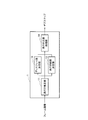
- FIG. 1 is a diagram showing an example of the configuration of the information processing apparatus of the present embodiment.
- FIG. 2 is a flowchart showing the flow of the depth compression process.
- FIG. 3 is a diagram showing an example of the display surface and the depth range of the key frame.
- FIG. 4 is a diagram showing an example of a display surface and a depth range of a certain frame.
- FIG. 5 is a diagram showing an example of a display surface and a depth range of a certain frame.
- FIG. 6 is a diagram showing an example of a display surface and a depth range of a certain frame.
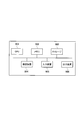
- FIG. 7 is a diagram showing an example of the hardware configuration of the information processing apparatus.
- the information processing apparatus of this embodiment will be described with reference to FIG.
- the information processing device 1 shown in FIG. 1 is a device that outputs a depth map used to generate a parallax image in a display system that displays a three-dimensional moving image.
- the depth map is information indicating the depth of each point of each frame of the moving image. For example, in the case of an 8-bit image, the depth of each pixel of each frame image is represented by 0 to 255.
- the information processing device 1 of FIG. 1 includes a depth estimation unit 11, a display surface determination unit 12, a depth range determination unit 13, and a depth compression processing unit 14.
- the depth estimation unit 11 inputs a frame image cut out from a moving image, estimates the depth at each position in the frame image, and outputs depth information.
- the frame image may be a monocular image or a stereo image.
- the information processing apparatus 1 may input the depth information calculated from the frame image from the outside without providing the depth estimation unit 11.
- the display surface determination unit 12 inputs depth information, determines the display surface by an arbitrary depth compression method, and outputs it.
- the display surface is a surface corresponding to the display surface of the display system when displaying an image in three dimensions. In a three-dimensional moving image, an object on the viewpoint side of the display surface is displayed in front of the display surface, and an object on the back side of the display surface is displayed on the back side of the display surface.
- the display surface is determined, for example, at a depth position near the center of the screen where the subject to be watched in the scene exists.
- the depth range determination unit 13 inputs depth information, determines the depth range by an arbitrary depth range determination method, and outputs the depth range.
- the display surface is set at the position of the object of interest in the three-dimensional image, and the depth range is from the 5th percentile to the 95th percentile of the depth around the object of interest.
- the depth range includes the display surface and is a range for expressing a stereoscopic effect on a 3D image display device such as a 3D television or a 3D projector. Outside the depth range, depth information is compressed by the depth compression processing unit 14 described later. For example, an object farther than the depth range is considered to be an object at the same depth position.
- the depth range is the range of processing to effectively express a three-dimensional effect and a sense of depth by subjectively setting it according to the background (outdoor, indoor) of the video scene and the number, shape, and size of the subject. be.
- the depth compression processing unit 14 inputs depth information, a display surface, and a depth range, compresses the depth information using the display surface and the depth range, and outputs a depth map.
- the depth compression processing unit 14 holds the display surface and the depth range of the key frame, and when the display surface of the current frame is within a predetermined range, the depth information is used by using the display surface and the depth range of the key frame. If the display surface of the current frame is outside the predetermined range, the display surface of the key frame and the depth range are corrected to compress the depth information.
- the key frame is a frame that serves as a delimiter in the moving image, and is, for example, the first frame in which the scene is switched. The user can also set keyframes at will.
- the depth information of each frame of the moving image is calculated by the depth estimation unit 11 or input from the outside.
- step S11 the display surface determination unit 12 determines the display surface of the key frame based on the depth information.
- the information on the display surface is transmitted to the depth compression processing unit 14.
- step S12 the depth range determination unit 13 determines the depth range of the key frame based on the depth information.
- the depth range is transmitted to the depth compression processing unit 14.
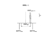
- FIG. 3 shows an example of the display surface DISP def at the key frame, the minimum value DEPTH min and the maximum value DEPTH max in the depth range.
- the viewpoint position is placed on the right side and the horizontal axis is set in the depth direction.
- the more to the left side of the figure the more it is displayed in the back side of the video, and the more to the right side, the more it is displayed in the front side of the video. Since FIGS. 3 to 6 show a person facing to the right, the person facing the front is displayed on the moving image.
- step S13 the depth compression processing unit 14 compresses the depth information using the display surface of the key frame and the depth range, and generates a depth map. For example, when each point on the depth map is represented by 0 to 255 (8 bits), the depth compression processing unit 14 maps the depth information from the minimum value DEPTH min to the maximum value DEPTH max in the depth range to 1 to 254. , Map farther than the minimum value DEPTH min to 0, and map to 255 before the maximum value DEPTH max.
- the depth compression processing unit 14 retains the display surface of the key frame and the depth range of the key frame, and is used in the depth compression processing after the next frame.
- the display system uses the depth map output by the information processing device 1 to generate a frame image for the right eye and a frame image for the left eye with parallax.
- step S14 the display surface determination unit 12 determines the display surface based on the depth information.
- the information on the display surface is transmitted to the depth compression processing unit 14.
- step S15 the depth compression processing unit 14 determines whether or not the display surface of the current frame is within a predetermined range.
- the predetermined range is a range before the minimum value DEPTH min of the depth range of the key frame and a range behind the maximum value DEPTH max.
- the predetermined range is 10% to 90% of the depth range of the key frame.
- a predetermined range can be set arbitrarily.
- the depth compression processing unit 14 advances the processing to step S17. For example, since the display surface DISP cur (t-1) at time t-1 in FIG. 4 exists within the predetermined range indicated by the arrow, the depth compression processing unit 14 advances the processing to step S17.
- step S16 the depth compression processing unit 14 changes the depth range according to the movement of the display surface.
- the minimum value DEPTH min and the maximum value DEPTH max in the depth range of are changed by DIFF.
- the display surface DISP def when the display surface approaches the viewpoint by DIFF, the display surface DISP def , the minimum value DEPTH min and the maximum value DEPTH max in the depth range are brought closer to the viewpoint by DIFF.
- the display surface DISP def When the display surface is separated from the viewpoint by DIFF, the display surface DISP def , the minimum value DEPTH min and the maximum value DEPTH max in the depth range are moved to the back side by DIFF.
- the movement amount DIFF for each frame is calculated by the following equation.
- DIFF MAX (DIFF min , DISP cur (t) -DISP cur (t-1) ) However, DIFF min > 0.
- step S17 the depth compression processing unit 14 performs depth compression processing using the display surface DISP def of the key frame, the minimum value DEPTH min and the maximum value DEPTH max of the depth range of the key frame, and generates a depth map.
- the display system uses the depth map output by the information processing apparatus 1 to generate a frame image for the right eye and a frame image for the left eye having parallax.
- the information processing device 1 When a new key frame is reached, such as when the scene changes, the information processing device 1 returns the process to step S11 and continues the process.
- step S16 only the maximum value DEPTH max of the depth range may be changed by the amount of DIFF.
- the minimum value DEPTH min of the depth range may be changed to the back side by the amount of DIFF.
- the information processing apparatus 1 of the present embodiment has a display surface determination unit 12 that determines a display surface for displaying a frame image three-dimensionally based on depth information calculated from a frame image of a moving image, and a stereoscopic display surface determination unit 12. It has a depth range determining unit 13 that determines a depth range that emphasizes the feeling, and a depth compression processing unit 14 that compresses depth information using the display surface and the depth range to generate a depth map. When the display surface is within a predetermined range, the depth compression processing unit 14 compresses the depth information using the display surface of the key frame determined by the key frame of the moving image and the depth range of the key frame, and the display surface compresses the depth information.
- the depth range of the keyframe is corrected and the depth information is compressed.
- a three-dimensional moving image when the gaze object moves in the depth direction while emphasizing the stereoscopic effect of the gaze object. It can alleviate the discomfort of the image.
- the information processing device 1 described above includes, for example, a central processing unit (CPU) 901, a memory 902, a storage 903, a communication device 904, an input device 905, and an output device 906, as shown in FIG.
- CPU central processing unit
- a general-purpose computer system including the above can be used.
- the information processing apparatus 1 is realized by the CPU 901 executing a predetermined program loaded on the memory 902.
- This program can be recorded on a computer-readable recording medium such as a magnetic disk, an optical disk, or a semiconductor memory, or can be distributed via a network.
Landscapes
- Engineering & Computer Science (AREA)
- Multimedia (AREA)
- Signal Processing (AREA)
- Testing, Inspecting, Measuring Of Stereoscopic Televisions And Televisions (AREA)
- Processing Or Creating Images (AREA)
Abstract
本実施形態の情報処理装置1は、動画のフレーム画像から算出した奥行き情報に基づき、フレーム画像を3次元表示する際のディスプレイ面と立体感を強調する奥行き範囲を決定するディスプレイ面決定部12と奥行き範囲決定部13と、ディスプレイ面と奥行き範囲を用いて奥行き情報を圧縮処理してデプスマップを生成する奥行き圧縮処理部14を有する。奥行き圧縮処理部14は、ディスプレイ面が所定の範囲内に存在する場合は、動画のキーフレームで決定したキーフレームのディスプレイ面とキーフレームの奥行き範囲を用いて奥行き情報を圧縮し、ディスプレイ面が所定の範囲外に存在する場合は、キーフレームの奥行き範囲を補正して奥行き情報を圧縮する。
Description
本発明は、情報処理装置、情報処理方法、およびプログラムに関する。
3次元画像において、深い奥行きをそのまま表現せずに、遠くの奥行き情報を圧縮することで、注視させたい被写体の立体感を強調できる。
非特許文献1では、3次元画像において、ディスプレイ面の前後が最も視差が効果的に感じられることを利用し、注目物の位置にディスプレイ面を設定する。注目物周辺の奥行きの5パーセンタイルから95パーセンタイルを奥行きの最小・最大として非線形に奥行きをマッピングし、奥行きの最小・最大範囲を超える奥行き情報は圧縮する。
Petr Kelnhofer, et al.,"GazeStereo3D: Seamless Disparity Manipulations,"ACM Transactions on Graphics - Proceedings of ACM SIGGRAPH 2016, Volume 35, Issue 4, 2016.
従来の奥行き圧縮手法をそのまま動画に適用した場合、各フレームにおいて注目すべき被写体の位置にディスプレイ面が設定される。そのため、被写体が奥行き方向に移動する動画において、被写体が飛び出したり、奥に進んだりするのではなく、背景が前後に移動するように見えてしまうという問題があった。
本発明は、上記に鑑みてなされたものであり、注視物体が奥行き方向に移動する際の3次元動画像の違和感を和らげることを目的とする。
本発明の一態様の情報処理装置は、動画のフレーム画像から算出した奥行き情報に基づき、前記フレーム画像を3次元表示する際のディスプレイ面と立体感を強調する奥行き範囲を決定する決定部と、前記ディスプレイ面と前記奥行き範囲を用いて前記奥行き情報を圧縮処理してデプスマップを生成する処理部を有し、前記処理部は、前記ディスプレイ面が所定の範囲内に存在する場合は、前記動画のキーフレームで決定したキーフレームのディスプレイ面とキーフレームの奥行き範囲を用いて奥行き情報を圧縮し、前記ディスプレイ面が所定の範囲外に存在する場合は、前記キーフレームの奥行き範囲を補正して奥行き情報を圧縮する。
本発明の一態様の情報処理装置は、コンピュータが実行する情報処理方法であって、動画のフレーム画像から算出した奥行き情報に基づき、前記フレーム画像を3次元表示する際のディスプレイ面と立体感を強調する奥行き範囲を決定するステップと、前記ディスプレイ面と前記奥行き範囲を用いて前記奥行き情報を圧縮処理してデプスマップを生成するステップを有し、前記奥行き情報の圧縮処理では、前記ディスプレイ面が所定の範囲内に存在する場合は、前記動画のキーフレームで決定したキーフレームのディスプレイ面とキーフレームの奥行き範囲を用いて奥行き情報を圧縮し、前記ディスプレイ面が所定の範囲外に存在する場合は、前記キーフレームの奥行き範囲を補正して奥行き情報を圧縮する。
本発明によれば、注視物体が奥行き方向に移動する際の3次元動画像の違和感を和らげることができる。
以下、本発明の実施の形態について図面を用いて説明する。
図1を参照し、本実施形態の情報処理装置について説明する。図1に示す情報処理装置1は、3次元動画を表示する表示システムにおいて視差画像を生成するために用いるデプスマップを出力する装置である。デプスマップは、動画の各フレームの各点の奥行きを示す情報であり、例えば8ビット画像の場合、各フレーム画像の各画素の奥行きを0~255で表したものである。
図1の情報処理装置1は、奥行き推定部11、ディスプレイ面決定部12、奥行き範囲決定部13、および奥行き圧縮処理部14を備える。
奥行き推定部11は、動画から切り出したフレーム画像を入力し、フレーム画像中の各位置における奥行きを推定して、奥行き情報を出力する。フレーム画像は、単眼画像であってもよいし、ステレオ画像であってもよい。なお、情報処理装置1は、奥行き推定部11を備えずに、フレーム画像から算出した奥行き情報を外部から入力してもよい。
ディスプレイ面決定部12は、奥行き情報を入力し、任意の奥行き圧縮手法で、ディスプレイ面を決定し、出力する。ディスプレイ面とは、画像を3次元表示する際に表示システムの表示面に対応する面である。3次元動画において、ディスプレイ面よりも視点側にある物体は表示面よりも手前に表示され、ディスプレイ面よりも奥側にある物体は表示面よりも奥側に表示される。ディスプレイ面は、例えば、画面の中央付近の、そのシーンで注視してもらいたい被写体が存在する奥行き位置に決定される。
奥行き範囲決定部13は、奥行き情報を入力し、任意の奥行き範囲決定手法で、奥行き範囲を決定し、出力する。例えば、非特許文献1のように、3次元画像において注目物の位置にディスプレイ面を設定し、注目物周辺の奥行きの5パーセンタイルから95パーセンタイルを奥行き範囲とする。奥行き範囲は、ディスプレイ面を含み、3Dテレビまたは3Dプロジェクタ等の3D映像表示装置で立体感を表現する範囲である。奥行き範囲外は、後述の奥行き圧縮処理部14により奥行き情報が圧縮される。例えば、奥行き範囲よりも遠くの物体は、同じ奥行き位置にある物体とされる。奥行き範囲とは映像シーンの背景(屋外、屋内)や被写体の数・形・大きさによって主観的に設定することで、立体感や奥行き感を効果的に表現するための処理の範囲のことである。
奥行き圧縮処理部14は、奥行き情報、ディスプレイ面、および奥行き範囲を入力し、ディスプレイ面と奥行き範囲を用いて奥行き情報を圧縮処理し、デプスマップを出力する。
奥行き圧縮処理部14は、キーフレームにおけるディスプレイ面と奥行き範囲を保持しておき、現フレームのディスプレイ面が所定の範囲内に存在する場合は、キーフレームのディスプレイ面と奥行き範囲を用いて奥行き情報を圧縮し、現フレームのディスプレイ面が所定の範囲外に存在する場合は、キーフレームのディスプレイ面と奥行き範囲を補正して奥行き情報を圧縮する。キーフレームとは、動画中の区切りとなるフレームであり、例えば、シーンが切り替わった最初のフレームである。ユーザーが任意にキーフレームを設定することもできる。
次に、図2を参照し、奥行き圧縮処理の流れについて説明する。なお、動画の各フレームの奥行き情報は、奥行き推定部11が算出するか、あるいは外部から入力するものとする。
ステップS11にて、ディスプレイ面決定部12は、奥行き情報に基づいてキーフレームのディスプレイ面を決定する。ディスプレイ面の情報は、奥行き圧縮処理部14へ送信される。
ステップS12にて、奥行き範囲決定部13は、奥行き情報に基づいてキーフレームの奥行き範囲を決定する。奥行き範囲は、奥行き圧縮処理部14へ送信される。
図3に、キーフレームでのディスプレイ面DISPdefと、奥行き範囲の最小値DEPTHminと最大値DEPTHmaxの一例を示す。なお、図3~6では、視点位置を右側に置き、横軸を奥行き方向とした。つまり、図上で左側に行くほど動画では奥側に表示され、右側に行くほど動画では手前に表示される。図3~6では、右向きの人物を図示しているので、動画上では、正面を向いた人物が表示される。
ステップS13にて、奥行き圧縮処理部14は、キーフレームのディスプレイ面と奥行き範囲を用いて奥行き情報を圧縮し、デプスマップを生成する。例えば、デプスマップ上の各点を0~255(8ビット)で表す場合、奥行き圧縮処理部14は、奥行き範囲の最小値DEPTHminから最大値DEPTHmaxまでの奥行き情報を1~254にマッピングし、最小値DEPTHminより遠くを0、最大値DEPTHmaxより手前を255にマッピングする。
奥行き圧縮処理部14は、キーフレームのディスプレイ面とキーフレームの奥行き範囲を保持しておき、次のフレーム以降の奥行き圧縮処理で利用する。
表示システムは、情報処理装置1の出力したデプスマップを用い、視差を持つ右眼用フレーム画像と左眼用フレーム画像を生成する。
キーフレームの次のフレーム以降は、以下のステップS14~S17の処理を繰り返す。
ステップS14にて、ディスプレイ面決定部12は、奥行き情報に基づいてディスプレイ面を決定する。ディスプレイ面の情報は、奥行き圧縮処理部14へ送信される。
ステップS15にて、奥行き圧縮処理部14は、現フレームのディスプレイ面が所定の範囲内であるか否か判定する。所定の範囲は、図4に示すように、キーフレームの奥行き範囲の最小値DEPTHminより手前で、最大値DEPTHmaxより奥側の範囲とする。例えば、所定の範囲は、キーフレームの奥行き範囲の10%~90%の範囲とする。所定の範囲は任意に設定可能である。
ディスプレイ面が所定の範囲内の場合、奥行き圧縮処理部14は処理をステップS17に進める。例えば、図4の時間t-1のディスプレイ面DISPcur(t-1)は矢印で示した所定の範囲内に存在するので、奥行き圧縮処理部14は処理をステップS17に進める。
ディスプレイ面が所定の範囲を超えた場合、ステップS16にて、奥行き圧縮処理部14はディスプレイ面の移動に合わせて、奥行き範囲を変更する。
例えば、図5の時間tのディスプレイ面DISPcur(t)は所定の範囲を超えているので、奥行き圧縮処理部14は保持するキーフレームのディスプレイ面とキーフレームの奥行き範囲を変更する。より具体的には、奥行き圧縮処理部14は、前フレームからのディスプレイ面の移動量DIFF=DISPcur(t)-DISPcur(t-1)を求め、キーフレームのディスプレイ面DISPdef、キーフレームの奥行き範囲の最小値DEPTHminと最大値DEPTHmaxをDIFF分だけ変更する。例えば、ディスプレイ面が視点にDIFF分近づいた場合、ディスプレイ面DISPdef、奥行き範囲の最小値DEPTHminと最大値DEPTHmaxをDIFF分だけ視点方向に近づける。ディスプレイ面が視点からDIFF分離れた場合、ディスプレイ面DISPdef、奥行き範囲の最小値DEPTHminと最大値DEPTHmaxをDIFF分だけ奥側に移動する。
なお、現フレームのディスプレイ面DISPcur(t)が所定の範囲を超えた後、DISPdef=DISPcur(t)となるまで、毎フレーム、キーフレームのディスプレイ面DISPdef、キーフレームの奥行き範囲の最小値DEPTHminと最大値DEPTHmaxを変更してもよい。この場合、フレームごとの移動量DIFFは次式で求める。
DIFF=MAX(DIFFmin,DISPcur(t)-DISPcur(t-1))
ただしDIFFmin>0である。
ただしDIFFmin>0である。
ディスプレイ面DISPcur(t)の動きが止まった場合でも、キーフレームのディスプレイ面DISPdefはDIFFminの速度で現フレームのディスプレイ面DISPcur(t)に毎フレーム近づいていく。DISPdef=DISPcur(t)となった後は、ステップS15で現フレームのディスプレイ面が所定の範囲を超えたか否か判定する処理に戻る。
ステップS17にて、奥行き圧縮処理部14は、キーフレームのディスプレイ面DISPdef、キーフレームの奥行き範囲の最小値DEPTHminと最大値DEPTHmaxを用いて奥行き圧縮処理を行い、デプスマップを生成する。表示システムは、情報処理装置1の出力したデプスマップを用い、視差を持つ右眼用フレーム画像と左眼用フレーム画像を生成する。
シーンが変わるなど、新たなキーフレームになると、情報処理装置1は、処理をステップS11に戻して処理を続ける。
なお、ステップS16の奥行き範囲を変更する処理では、図6に示すように、奥行き範囲の最大値DEPTHmaxのみをDIFF分だけ変更してもよい。現フレームのディスプレイ面DISPcur(t)が所定の範囲から奥側方向に超える場合は、奥行き範囲の最小値DEPTHminを奥側にDIFF分だけ変更してもよい。
以上説明したように、本実施形態の情報処理装置1は、動画のフレーム画像から算出した奥行き情報に基づき、フレーム画像を3次元表示する際のディスプレイ面を決定するディスプレイ面決定部12と、立体感を強調する奥行き範囲を決定する奥行き範囲決定部13と、ディスプレイ面と奥行き範囲を用いて奥行き情報を圧縮処理してデプスマップを生成する奥行き圧縮処理部14を有する。奥行き圧縮処理部14は、ディスプレイ面が所定の範囲内に存在する場合は、動画のキーフレームで決定したキーフレームのディスプレイ面とキーフレームの奥行き範囲を用いて奥行き情報を圧縮し、ディスプレイ面が所定の範囲外に存在する場合は、キーフレームの奥行き範囲を補正して奥行き情報を圧縮する。本実施形態では、注視物体が奥行き範囲を超えそうになった場合にのみディスプレイ面を追随することで、注視物体の立体感を強調しながら、注視物体が奥行き方向に移動する際の3次元動画像の違和感を和らげることができる。
上記説明した情報処理装置1には、例えば、図7に示すような、中央演算処理装置(CPU)901と、メモリ902と、ストレージ903と、通信装置904と、入力装置905と、出力装置906とを備える汎用的なコンピュータシステムを用いることができる。このコンピュータシステムにおいて、CPU901がメモリ902上にロードされた所定のプログラムを実行することにより、情報処理装置1が実現される。このプログラムは磁気ディスク、光ディスク、半導体メモリ等のコンピュータ読み取り可能な記録媒体に記録することも、ネットワークを介して配信することもできる。
1…情報処理装置
11…推定部
12…ディスプレイ面決定部
13…奥行き範囲決定部
14…奥行き圧縮処理部
11…推定部
12…ディスプレイ面決定部
13…奥行き範囲決定部
14…奥行き圧縮処理部
Claims (7)
- 動画のフレーム画像から算出した奥行き情報に基づき、前記フレーム画像を3次元表示する際のディスプレイ面と立体感を強調する奥行き範囲を決定する決定部と、
前記ディスプレイ面と前記奥行き範囲を用いて前記奥行き情報を圧縮処理してデプスマップを生成する処理部を有し、
前記処理部は、前記ディスプレイ面が所定の範囲内に存在する場合は、前記動画のキーフレームで決定したキーフレームのディスプレイ面とキーフレームの奥行き範囲を用いて奥行き情報を圧縮し、前記ディスプレイ面が所定の範囲外に存在する場合は、前記キーフレームの奥行き範囲を補正して奥行き情報を圧縮する
情報処理装置。 - 請求項1に記載の情報処理装置であって、
前記所定の範囲は、前記キーフレームの奥行き範囲内に設定された範囲である
情報処理装置。 - 請求項1または2に記載の情報処理装置であって、
前記処理部は、前記ディスプレイ面が所定の範囲外に存在する場合は、当該ディスプレイ面の移動量に応じて、前記キーフレームのディスプレイ面と前記キーフレームの奥行き範囲を補正する
情報処理装置。 - 請求項3に記載の情報処理装置であって、
前記処理部は、前記ディスプレイ面が所定の範囲外に出た後、前記キーフレームのディスプレイ面が現フレームのディスプレイ面と同じ位置になるまで前記キーフレームのディスプレイ面と前記キーフレームの奥行き範囲を毎フレーム補正する
情報処理装置。 - 請求項1または2に記載の情報処理装置であって、
前記処理部は、前記ディスプレイ面が所定の範囲外に存在する場合は、前記キーフレームの奥行き範囲の一方を広げる
情報処理装置。 - コンピュータが実行する情報処理方法であって、
動画のフレーム画像から算出した奥行き情報に基づき、前記フレーム画像を3次元表示する際のディスプレイ面と立体感を強調する奥行き範囲を決定するステップと、
前記ディスプレイ面と前記奥行き範囲を用いて前記奥行き情報を圧縮処理してデプスマップを生成するステップを有し、
前記奥行き情報の圧縮処理では、前記ディスプレイ面が所定の範囲内に存在する場合は、前記動画のキーフレームで決定したキーフレームのディスプレイ面とキーフレームの奥行き範囲を用いて奥行き情報を圧縮し、前記ディスプレイ面が所定の範囲外に存在する場合は、前記キーフレームの奥行き範囲を補正して奥行き情報を圧縮する
情報処理方法。 - 請求項1ないし5のいずれかに記載の情報処理装置の各部としてコンピュータを動作させるプログラム。
Priority Applications (2)
| Application Number | Priority Date | Filing Date | Title |
|---|---|---|---|
| JP2022522132A JP7406166B2 (ja) | 2020-05-12 | 2020-05-12 | 情報処理装置、情報処理方法、およびプログラム |
| PCT/JP2020/018951 WO2021229679A1 (ja) | 2020-05-12 | 2020-05-12 | 情報処理装置、情報処理方法、およびプログラム |
Applications Claiming Priority (1)
| Application Number | Priority Date | Filing Date | Title |
|---|---|---|---|
| PCT/JP2020/018951 WO2021229679A1 (ja) | 2020-05-12 | 2020-05-12 | 情報処理装置、情報処理方法、およびプログラム |
Publications (1)
| Publication Number | Publication Date |
|---|---|
| WO2021229679A1 true WO2021229679A1 (ja) | 2021-11-18 |
Family
ID=78525993
Family Applications (1)
| Application Number | Title | Priority Date | Filing Date |
|---|---|---|---|
| PCT/JP2020/018951 WO2021229679A1 (ja) | 2020-05-12 | 2020-05-12 | 情報処理装置、情報処理方法、およびプログラム |
Country Status (2)
| Country | Link |
|---|---|
| JP (1) | JP7406166B2 (ja) |
| WO (1) | WO2021229679A1 (ja) |
Citations (6)
| Publication number | Priority date | Publication date | Assignee | Title |
|---|---|---|---|---|
| JP2006197240A (ja) * | 2005-01-13 | 2006-07-27 | Nippon Telegr & Teleph Corp <Ntt> | 3次元表示方法および3次元表示装置 |
| JP2012257022A (ja) * | 2011-06-08 | 2012-12-27 | Sony Corp | 画像処理装置および方法、並びにプログラム |
| JP2013058849A (ja) * | 2011-09-07 | 2013-03-28 | Sharp Corp | 立体画像処理装置、立体画像処理方法、及びプログラム |
| JP2013078101A (ja) * | 2011-09-13 | 2013-04-25 | Sharp Corp | 画像処理装置、画像撮像装置および画像表示装置 |
| JP2014053782A (ja) * | 2012-09-07 | 2014-03-20 | Sharp Corp | 立体画像データ処理装置、および、立体画像データ処理方法 |
| JP2015156607A (ja) * | 2014-02-21 | 2015-08-27 | ソニー株式会社 | 画像処理装置、画像処理装置、及び電子機器 |
-
2020
- 2020-05-12 JP JP2022522132A patent/JP7406166B2/ja active Active
- 2020-05-12 WO PCT/JP2020/018951 patent/WO2021229679A1/ja active Application Filing
Patent Citations (6)
| Publication number | Priority date | Publication date | Assignee | Title |
|---|---|---|---|---|
| JP2006197240A (ja) * | 2005-01-13 | 2006-07-27 | Nippon Telegr & Teleph Corp <Ntt> | 3次元表示方法および3次元表示装置 |
| JP2012257022A (ja) * | 2011-06-08 | 2012-12-27 | Sony Corp | 画像処理装置および方法、並びにプログラム |
| JP2013058849A (ja) * | 2011-09-07 | 2013-03-28 | Sharp Corp | 立体画像処理装置、立体画像処理方法、及びプログラム |
| JP2013078101A (ja) * | 2011-09-13 | 2013-04-25 | Sharp Corp | 画像処理装置、画像撮像装置および画像表示装置 |
| JP2014053782A (ja) * | 2012-09-07 | 2014-03-20 | Sharp Corp | 立体画像データ処理装置、および、立体画像データ処理方法 |
| JP2015156607A (ja) * | 2014-02-21 | 2015-08-27 | ソニー株式会社 | 画像処理装置、画像処理装置、及び電子機器 |
Also Published As
| Publication number | Publication date |
|---|---|
| JP7406166B2 (ja) | 2023-12-27 |
| JPWO2021229679A1 (ja) | 2021-11-18 |
Similar Documents
| Publication | Publication Date | Title |
|---|---|---|
| US11196973B2 (en) | Providing apparatus, providing method and computer readable storage medium for performing processing relating to a virtual viewpoint image | |
| TWI528781B (zh) | 用以訂製立體內容之三維效果的方法及裝置 | |
| US20130051659A1 (en) | Stereoscopic image processing device and stereoscopic image processing method | |
| TWI574544B (zh) | 基於顯著性之像差映射 | |
| KR101502362B1 (ko) | 영상처리 장치 및 방법 | |
| US10095953B2 (en) | Depth modification for display applications | |
| US20050253924A1 (en) | Method and apparatus for processing three-dimensional images | |
| KR100918007B1 (ko) | 3차원 모델의 스케일링 방법, 스케일링 유닛 및 화상디스플레이 장치 | |
| US20050185048A1 (en) | 3-D display system, apparatus, and method for reconstructing intermediate-view video | |
| EP2728887B1 (en) | Image processing apparatus and image processing method thereof | |
| JP2016540401A (ja) | 3d表示のための深度マップのリマッピング | |
| CN104010180A (zh) | 三维视频滤波方法和装置 | |
| EP2755390A1 (en) | Stereoscopic image processing apparatus, stereoscopic image processing method, and program | |
| JP4806088B1 (ja) | 画像変換装置、画像変換装置の制御方法、画像変換装置制御プログラムおよび記録媒体 | |
| WO2013047007A1 (ja) | 視差量調整装置およびその動作制御方法 | |
| WO2021229679A1 (ja) | 情報処理装置、情報処理方法、およびプログラム | |
| EP2932710B1 (en) | Method and apparatus for segmentation of 3d image data | |
| JP5127973B1 (ja) | 映像処理装置、映像処理方法および映像表示装置 | |
| US12081722B2 (en) | Stereo image generation method and electronic apparatus using the same | |
| Tseng et al. | Automatically optimizing stereo camera system based on 3D cinematography principles | |
| KR101783608B1 (ko) | 전자 장치 및 입체감 조정 방법 | |
| US20140198098A1 (en) | Experience Enhancement Environment | |
| US20140055579A1 (en) | Parallax adjustment device, three-dimensional image generation device, and method of adjusting parallax amount | |
| Graphics et al. | Volumetric Video Streaming Data Reduction Method Using Front-mesh 3D Data | |
| CN115619916A (zh) | 一种渲染方法、装置和设备 |
Legal Events
| Date | Code | Title | Description |
|---|---|---|---|
| 121 | Ep: the epo has been informed by wipo that ep was designated in this application |
Ref document number: 20935508 Country of ref document: EP Kind code of ref document: A1 |
|
| ENP | Entry into the national phase |
Ref document number: 2022522132 Country of ref document: JP Kind code of ref document: A |
|
| NENP | Non-entry into the national phase |
Ref country code: DE |
|
| 122 | Ep: pct application non-entry in european phase |
Ref document number: 20935508 Country of ref document: EP Kind code of ref document: A1 |