WO2021220893A1 - 画像処理装置、画像処理方法、及びプログラム - Google Patents
画像処理装置、画像処理方法、及びプログラム Download PDFInfo
- Publication number
- WO2021220893A1 WO2021220893A1 PCT/JP2021/016071 JP2021016071W WO2021220893A1 WO 2021220893 A1 WO2021220893 A1 WO 2021220893A1 JP 2021016071 W JP2021016071 W JP 2021016071W WO 2021220893 A1 WO2021220893 A1 WO 2021220893A1
- Authority
- WO
- WIPO (PCT)
- Prior art keywords
- image
- screen
- displayed
- specific area
- imaging
- Prior art date
- Legal status (The legal status is an assumption and is not a legal conclusion. Google has not performed a legal analysis and makes no representation as to the accuracy of the status listed.)
- Ceased
Links
Images


Classifications
-
- H—ELECTRICITY
- H04—ELECTRIC COMMUNICATION TECHNIQUE
- H04N—PICTORIAL COMMUNICATION, e.g. TELEVISION
- H04N21/00—Selective content distribution, e.g. interactive television or video on demand [VOD]
- H04N21/40—Client devices specifically adapted for the reception of or interaction with content, e.g. set-top-box [STB]; Operations thereof
- H04N21/47—End-user applications
- H04N21/472—End-user interface for requesting content, additional data or services; End-user interface for interacting with content, e.g. for content reservation or setting reminders, for requesting event notification, for manipulating displayed content
- H04N21/4728—End-user interface for requesting content, additional data or services; End-user interface for interacting with content, e.g. for content reservation or setting reminders, for requesting event notification, for manipulating displayed content for selecting a Region Of Interest [ROI], e.g. for requesting a higher resolution version of a selected region
-
- H—ELECTRICITY
- H04—ELECTRIC COMMUNICATION TECHNIQUE
- H04N—PICTORIAL COMMUNICATION, e.g. TELEVISION
- H04N21/00—Selective content distribution, e.g. interactive television or video on demand [VOD]
- H04N21/20—Servers specifically adapted for the distribution of content, e.g. VOD servers; Operations thereof
- H04N21/21—Server components or server architectures
- H04N21/218—Source of audio or video content, e.g. local disk arrays
- H04N21/21805—Source of audio or video content, e.g. local disk arrays enabling multiple viewpoints, e.g. using a plurality of cameras
-
- H—ELECTRICITY
- H04—ELECTRIC COMMUNICATION TECHNIQUE
- H04N—PICTORIAL COMMUNICATION, e.g. TELEVISION
- H04N21/00—Selective content distribution, e.g. interactive television or video on demand [VOD]
- H04N21/80—Generation or processing of content or additional data by content creator independently of the distribution process; Content per se
- H04N21/81—Monomedia components thereof
- H04N21/8146—Monomedia components thereof involving graphical data, e.g. 3D object, 2D graphics
- H04N21/8153—Monomedia components thereof involving graphical data, e.g. 3D object, 2D graphics comprising still images, e.g. texture, background image
-
- H—ELECTRICITY
- H04—ELECTRIC COMMUNICATION TECHNIQUE
- H04N—PICTORIAL COMMUNICATION, e.g. TELEVISION
- H04N21/00—Selective content distribution, e.g. interactive television or video on demand [VOD]
- H04N21/80—Generation or processing of content or additional data by content creator independently of the distribution process; Content per se
- H04N21/85—Assembly of content; Generation of multimedia applications
- H04N21/854—Content authoring
- H04N21/8545—Content authoring for generating interactive applications
-
- H—ELECTRICITY
- H04—ELECTRIC COMMUNICATION TECHNIQUE
- H04N—PICTORIAL COMMUNICATION, e.g. TELEVISION
- H04N23/00—Cameras or camera modules comprising electronic image sensors; Control thereof
- H04N23/60—Control of cameras or camera modules
-
- H—ELECTRICITY
- H04—ELECTRIC COMMUNICATION TECHNIQUE
- H04N—PICTORIAL COMMUNICATION, e.g. TELEVISION
- H04N5/00—Details of television systems
- H04N5/222—Studio circuitry; Studio devices; Studio equipment
-
- H—ELECTRICITY
- H04—ELECTRIC COMMUNICATION TECHNIQUE
- H04N—PICTORIAL COMMUNICATION, e.g. TELEVISION
- H04N21/00—Selective content distribution, e.g. interactive television or video on demand [VOD]
- H04N21/40—Client devices specifically adapted for the reception of or interaction with content, e.g. set-top-box [STB]; Operations thereof
- H04N21/47—End-user applications
- H04N21/482—End-user interface for programme selection
Definitions
- the technology of the present disclosure relates to an image processing device, an image processing method, and a program.
- Japanese Unexamined Patent Publication No. 2003-283450 discloses a receiving device that receives content transmitted by the content transmitting device via a broadcast wave or a communication line in a predetermined broadcasting band.
- the receiving device described in JP-A-2003-283450 includes information receiving means, designated receiving means, transmitting means, detecting means, and content receiving means.
- the information receiving means receives the content specific information that specifies the receivable content and the broadcast content information that indicates the content that is being broadcast by the broadcast wave of the predetermined broadcast band.
- the designated receiving means receives at least one designation from the user among the receivable contents.
- the transmission means transmits the content specific information that identifies the content related to the designation to the content transmission device via the communication line.
- the detection means refers to the broadcast content information and detects whether or not the content according to the designation is being broadcast by the broadcast wave of the predetermined broadcast band. When the content according to the designation is not broadcast by the detection means, the content receiving means receives the content specified by the content specific information transmitted by the transmitting means from the content transmitting device via the communication line. ..
- the receiving device described in Japanese Patent Application Laid-Open No. 2003-283450 is a receiving device that displays the received content on the display device, and displays a list of receivable contents on the display device based on the content specific information. It has the means.
- the designated receiving means is characterized in that at least one content specific information designation is received from the user from the list displayed by the display means.
- One embodiment according to the technique of the present disclosure processes an image corresponding to a designated specific area of the imaged area image for a viewer of the imaged area image obtained by capturing the imaged area.
- an image processing apparatus an image processing method, and a program capable of viewing a specific area processed image.
- the first aspect according to the technique of the present disclosure includes a processor and a memory built in or connected to the processor, and the processor displays an image pickup area image obtained by capturing an image pickup area. Acquiring specific area information indicating a specific area specified on the imaging area image screen, and processing an image corresponding to the specific area indicated by the specific area information among a plurality of images obtained by imaging the imaging area.
- This is an image processing device that outputs a processed image of a specific area.
- a second aspect according to the technique of the present disclosure is an image processing apparatus according to the first aspect, wherein the image pickup area image screen is a screen obtained by capturing another screen on which the image pickup area image is displayed. Is.
- a third aspect according to the technique of the present disclosure is an image processing device according to the first aspect or the second aspect in which the image capture region image includes a live broadcast image.
- a fourth aspect according to the technique of the present disclosure is a first aspect in which the imaging region image screen has a plurality of split screens on which the imaging region image is displayed, and a specific region is designated by selecting the split screen.
- the image processing apparatus according to any one of the third aspects from the above aspect.
- a fifth aspect according to the technique of the present disclosure is an image processing device according to a fourth aspect, in which an image of an imaging region is divided and displayed on a plurality of split screens.
- a sixth aspect according to the technique of the present disclosure is a plurality of unique images obtained by capturing an imaging region image by imaging methods having different imaging regions, and a plurality of unique images are displayed on a plurality of split screens.
- a seventh aspect according to the technique of the present disclosure is an image processing device according to any one of the fourth to sixth aspects, in which a plurality of split screens are displayed separately on a plurality of displays.
- the eighth aspect according to the technique of the present disclosure is any one of the first to seventh aspects in which the processor generates and outputs a specific area processed image based on the timing in which the specific area is designated.
- This is an image processing device according to an aspect.
- the captured region image is displayed on the display as a frame-advanced moving image, and a specific region is designated by selecting one of a plurality of frames constituting the frame-advanced moving image.
- the image processing apparatus according to any one of the first to eighth aspects.
- a tenth aspect according to the technique of the present disclosure is a plurality of imaging from a menu screen capable of identifying a plurality of imaging scenes in which at least one of a position, an orientation, and an angle of view at which imaging is performed with respect to an imaging region is different.
- the image processing apparatus according to any one of the first to ninth aspects, in which a specific area is designated by selecting any one of the scenes.
- the eleventh aspect according to the technique of the present disclosure is the tenth aspect from the first aspect in which a region corresponding to an object selected from object identification information capable of identifying a plurality of objects included in an imaging region is designated as a specific region. It is an image processing apparatus which concerns on any one aspect of the above aspect.
- a twelfth aspect according to the technique of the present disclosure is any of the first to eleventh aspects in which the processor outputs the specific area processed image to the display device to display the specific area processed image on the display device.
- This is an image processing device according to one aspect.
- a thirteenth aspect according to the technique of the present disclosure is any one of the first to twelfth aspects in which the processor changes the processing content of the image for a specific area in response to an instruction given from the outside.
- This is an image processing unit according to the above.
- a fourteenth aspect according to the technique of the present disclosure is an image processing device according to any one of the first to thirteenth aspects in which the specific area processed image is a virtual viewpoint image.
- a fifteenth aspect according to the technique of the present disclosure is to acquire specific area information indicating a specific area designated on the image pickup area image screen on which the image pickup area image obtained by capturing the image pickup area is displayed. , And, among a plurality of images obtained by capturing the imaging region, among a plurality of images including a virtual viewpoint image, a specific region processing is performed by processing an image corresponding to the specific region indicated by the specific region information.
- a sixteenth aspect according to the technique of the present disclosure is to provide a computer with specific area information indicating a specific area designated on an imaging area image screen on which an imaging area image obtained by imaging the imaging area is displayed.
- a plurality of images obtained by acquiring and capturing an imaging region, and among a plurality of images including a virtual viewpoint image, an image corresponding to a specific region indicated by specific region information is processed.
- This is a program for executing a process including outputting a processed image of a specific area.
- FIG. 5 is a schematic plan view showing an example of a mode in which a plurality of physical cameras and a plurality of virtual cameras used in the image processing system according to the embodiment are installed in a soccer field.
- FIG. 5 is a block diagram which shows an example of the hardware composition of the electric system of the image processing apparatus which concerns on embodiment.
- FIG. 5 is a screen view showing an example of a physical camera moving image screen obtained by capturing a screen displayed on a television receiver by a physical camera of a user device.
- FIG. 5 is a conceptual diagram showing an example of a mode in which a split screen image is transmitted to an image processing device by a user device included in the image processing system according to the embodiment. It is a block diagram which shows an example of the main part function of the image processing apparatus which concerns on embodiment. It is a conceptual diagram which shows an example of the processing content of the communication I / F for a user device of the image processing apparatus which concerns on embodiment, the acquisition part, and the search part.
- FIG. 5 is a conceptual diagram showing an example of a mode in which a screen number and a television screen capture time are transmitted to the image processing device 12 by a user device.
- FIG. 5 is a perspective view showing an example of a mode in which displays of various types of devices are imaged by a physical camera of a user device. It is a block diagram which shows an example of the mode in which the processing output program is installed in the computer of an image processing apparatus from the storage medium which stores the processing output program.
- CPU is an abbreviation for "Central Processing Unit”.
- RAM is an abbreviation for "Random Access Memory”.
- SSD is an abbreviation for “Solid State Drive”.
- HDD is an abbreviation for “Hard Disk Drive”.
- EEPROM refers to the abbreviation of "Electrically Erasable and Programmable Read Only Memory”.
- I / F refers to the abbreviation of "Interface”.
- IC refers to the abbreviation of "Integrated Circuit”.
- ASIC refers to the abbreviation of "Application Specific Integrated Circuit”.
- PLD refers to the abbreviation of "Programmable Logic Device”.
- FPGA refers to the abbreviation of "Field-Programmable Gate Array”.
- SoC is an abbreviation for "System-on-a-chip".
- CMOS is an abbreviation for "Complementary Metal Oxide Semiconductor”.
- CCD refers to the abbreviation of "Charge Coupled Device”.
- EL refers to the abbreviation for "Electro-Luminescence”.
- GPU refers to the abbreviation of "Graphics Processing Unit”.
- WAN is an abbreviation for "Wide Area Network”.
- LAN is an abbreviation for "Local Area Network”.
- 3D refers to the abbreviation of "3Dimension”.
- USB is an abbreviation for "Universal Serial Bus”.
- 5G refers to the abbreviation for "5th Generation”.
- LTE is an abbreviation for “Long Term Evolution”.
- WiFi is an abbreviation for "Wireless Fidelity”.
- RTC is an abbreviation for "Real Time Clock”.
- SNMP is an abbreviation for "Simple Network Time Protocol”.
- NTP is an abbreviation for "Network Time Protocol”.
- GPS is an abbreviation for "Global Positioning System”. Exif is an abbreviation for "Exchangeable image file format for digital still cameras”. ID refers to the abbreviation of "Identification”.
- GNSS is an abbreviation for "Global Navigation Satellite System”.
- a CPU is illustrated as an example of the “processor” according to the technology of the present disclosure, but the “processor” according to the technology of the present disclosure includes a plurality of processing devices such as a CPU and a GPU. It may be a combination of.
- the GPU operates under the control of the CPU and is responsible for executing image processing.
- match means, in addition to perfect match, an error generally allowed in the technical field to which the technology of the present disclosure belongs (to the extent that it does not contradict the purpose of the technology of the present disclosure). It refers to a match in terms of (meaning including error).
- the "same imaging time” has a meaning including an error generally allowed in the technical field to which the technology of the present disclosure belongs in addition to the completely same imaging time (in the present disclosure). It refers to the same imaging time (meaning including an error that does not go against the purpose of the technology).
- the image processing system 10 includes an image processing device 12, a user device 14, a plurality of physical cameras 16, and a television receiver 18.
- the user device 14 and the television receiver 18 are used by the user 22.
- a smartphone is applied as an example of the user device 14.
- the smartphone is merely an example, and may be, for example, a personal computer, a tablet terminal, or a portable multifunctional terminal such as a head-mounted display.
- the image processing device 12 includes a server 13 and a television broadcasting device 15.
- the server 13 is connected to the network 20.
- the number of servers 13 may be one or a plurality.
- the server 13 is merely an example, and may be, for example, at least one personal computer, or may be a combination of at least one server 13 and at least one personal computer.
- the television broadcasting device 15 is connected to the television receiver 18 via a cable 21.
- the television broadcasting device 15 transmits television broadcasting information indicating video (hereinafter, also referred to as “television video”) and audio for television broadcasting to the television receiver 18 via a cable 21.
- the television receiver 18 is an example of a "display device" according to the technology of the present disclosure, receives television broadcast information from the television broadcast device 15, and outputs video and audio indicated by the received television broadcast information.
- the transmission / reception of the television broadcast information by the wired system is illustrated here, the transmission / reception of the television broadcast information by the wireless system may be used.
- the network 20 is configured to include, for example, a WAN and / or a LAN.
- the network 20 includes, for example, a base station.
- the number of base stations is not limited to one, and there may be a plurality of base stations.
- the communication standards used in the base station include wireless communication standards such as 5G standard, LTE standard, WiFi (802.11) standard, and Bluetooth® standard.
- the network 20 establishes communication between the server 13 and the user device 14, and transmits and receives various information between the server 13 and the user device 14.
- the server 13 receives a request from the user device 14 via the network 20 and provides a service according to the request to the requesting user device 14 via the network 20.
- the wireless communication method is applied as an example of the communication method between the user device 14 and the network 20 and the communication method between the server 13 and the network 20, but this is only an example. However, it may be a wired communication method.
- the physical camera 16 actually exists as an object and is a visually recognizable imaging device.
- the physical camera 16 is an imaging device having a CMOS image sensor, and is equipped with an optical zoom function and / or a digital zoom function.
- CMOS image sensor instead of the CMOS image sensor, another type of image sensor such as a CCD image sensor may be applied.
- the zoom function is mounted on the plurality of physical cameras 16, but this is merely an example, and the zoom function may be mounted on a part of the plurality of physical cameras 16. The zoom function may not be mounted on the plurality of physical cameras 16.
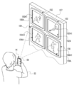
- a plurality of physical cameras 16 are installed in the soccer field 24.
- the plurality of physical cameras 16 have different imaging positions (hereinafter, also simply referred to as “positions”), and the imaging direction (hereinafter, simply referred to as “direction”) of each physical camera 16 can be changed.
- the soccer stadium 24 is provided with spectator seats 24B so as to surround the soccer field 24A.
- each of the plurality of physical cameras 16 is arranged in the spectator seat 24B so as to surround the soccer field 24A, and an area including the soccer field 24A is imaged as an imaging area.
- the imaging by the physical camera 16 refers to, for example, imaging at an angle of view including an imaging region.
- the concept of "imaging area” includes the concept of an area showing a part of the soccer field 24 in addition to the concept of the area showing the whole in the soccer field 24.
- the imaging region is changed according to the imaging position, the imaging direction, and the angle of view.
- each of the plurality of physical cameras 16 is arranged so as to surround the soccer field 24A, but the technique of the present disclosure is not limited to this, and for example, in the soccer field 24A.
- a plurality of physical cameras 16 may be arranged so as to surround a specific part. The positions and / or orientations of the plurality of physical cameras 16 can be changed, and it is determined to be generated according to the virtual viewpoint image requested by the user 22 or the like.
- At least one physical camera 16 is installed in an unmanned aerial vehicle (for example, a multi-rotorcraft unmanned aerial vehicle), and a bird's-eye view of the area including the soccer field 24A as an imaging area from the sky. You may make an image with.
- an unmanned aerial vehicle for example, a multi-rotorcraft unmanned aerial vehicle
- a bird's-eye view of the area including the soccer field 24A as an imaging area from the sky You may make an image with.
- the plurality of physical cameras 16 are wirelessly connected to the image processing device 12 via the antenna 12A.
- the plurality of physical cameras 16 transmit the captured image 46B obtained by capturing the imaging region to the image processing device 12.
- the captured images 46B transmitted from the plurality of physical cameras 16 are received by the antenna 12A.
- the captured image 46B received by the antenna 12A is acquired by the server 13 and the television broadcasting device 15.
- the television broadcasting device 15 transmits the moving images of the physical cameras acquired from the plurality of physical cameras 16 via the antenna 12A as television images to the television receiver 18 via the cable 21.
- the physical camera moving image is a moving image composed of a plurality of captured images 46B arranged in chronological order.
- the television receiver 18 receives the television image transmitted from the television broadcasting device 15 and outputs the received television image.
- the image processing device 12 acquires an image captured image 46B showing an image pickup region when observed from each position of the plurality of physical cameras 16 from each of the plurality of physical cameras 16.
- the captured image 46B is a frame image showing an imaging region when observed from the position of the physical camera 16. That is, the captured image 46B is obtained by capturing the imaging region by each of the plurality of physical cameras 16.
- the captured image 46B is assigned a physical camera ID that identifies the physical camera 16 used for imaging and a time when the image was taken by the physical camera 16 (hereinafter, also referred to as “physical camera imaging time”) for each frame. Has been done. Further, the captured image 46B is also provided with physical camera installation position information capable of specifying the installation position (imaging position) of the physical camera 16 used for imaging for each frame.
- the server 13 generates an image using 3D polygons by synthesizing a plurality of captured images 46B obtained by capturing an imaging region by a plurality of physical cameras 16. Then, the server 13 generates a virtual viewpoint image 46C indicating the imaging region when the imaging region is observed from an arbitrary position and an arbitrary direction, frame by frame, based on the image using the generated 3D polygon.
- the captured image 46B is an image obtained by being captured by the physical camera 16
- the virtual viewpoint image 46C is a virtual imaging device, that is, a virtual image from an arbitrary position and an arbitrary direction. It can be considered that the image is obtained by capturing the imaging region by the camera 42.
- the virtual camera 42 is a virtual camera that does not actually exist as an object and is not visually recognized.
- virtual cameras 42 are installed at a plurality of locations in the soccer field 24 (see FIG. 3). All virtual cameras 42 are installed at different positions from each other. Further, all the virtual cameras 42 are installed at different positions from all the physical cameras 16. That is, all the physical cameras 16 and all the virtual cameras 42 are installed at different positions from each other.
- a virtual camera ID that identifies the virtual camera 42 used for imaging and a time at which imaging is performed by the virtual camera 42 (hereinafter, also referred to as “virtual camera imaging time”) are set for each frame. Has been granted. Further, the virtual viewpoint image 46C is provided with virtual camera installation position information capable of specifying the installation position (imaging position) of the virtual camera 42 used for imaging.
- camera installation position information when it is not necessary to separately explain the physical camera installation position information and the virtual camera installation position information, it is also referred to as “camera installation position information”.
- the camera ID, the imaging time, and the camera installation position information are added to each camera image by, for example, the Exif method.
- the server 13 holds, for example, camera images for a predetermined time (for example, several hours to several tens of hours). Therefore, for example, the server 13 acquires a camera image at a designated imaging time from a group of camera images for a predetermined time, and processes the acquired camera image.
- a predetermined time for example, several hours to several tens of hours.
- the position (hereinafter, also referred to as “virtual camera position”) 42A and the orientation (hereinafter, also referred to as “virtual camera orientation”) 42B of the virtual camera 42 can be changed.
- the angle of view of the virtual camera 42 can also be changed.
- the virtual camera position 42A is referred to, but in general, the virtual camera position 42A is also referred to as a viewpoint position. Further, in the present embodiment, it is referred to as a virtual camera orientation 42B, but in general, the virtual camera orientation 42B is also referred to as a line-of-sight direction.
- the viewpoint position means, for example, the position of the viewpoint of a virtual person
- the line-of-sight direction means, for example, the direction of the line of sight of a virtual person.
- a virtual camera is used for explanation, but it is not essential to use a virtual camera.
- “Installing a virtual camera” means determining the viewpoint position, line-of-sight direction, and / or angle of view for generating the virtual viewpoint image 46C. Therefore, for example, the present invention is not limited to the mode in which an object such as a virtual camera is installed in the imaging region on a computer, and another method such as numerically specifying the coordinates and / or direction of the viewpoint position may be used.
- "capturing with a virtual camera” means generating a virtual viewpoint image 46C corresponding to the case where the imaging region is viewed from the position and direction in which the "virtual camera is installed".
- the server 13 sets the position of a person (hereinafter, also referred to as “target person”) designated as the target subject among the soccer player, the referee, and the like in the soccer field 24A as the virtual camera position, and the line of sight of the target person. It is also possible to set the orientation as the virtual camera orientation.
- target person a person designated as the target subject among the soccer player, the referee, and the like in the soccer field 24A as the virtual camera position, and the line of sight of the target person. It is also possible to set the orientation as the virtual camera orientation.
- virtual cameras 42 are installed at a plurality of locations in the soccer field 24A and at a plurality of locations around the soccer field 24A.
- the installation mode of the virtual camera 42 shown in FIG. 3 is merely an example.
- the virtual camera 42 may not be installed in the soccer field 24A and the virtual camera 42 may be installed only around the soccer field 24A, or the virtual camera 42 may not be installed around the soccer field 24A and the soccer may be installed.
- the virtual camera 42 may be installed only in the field 24A.
- the number of virtual cameras 42 installed may be larger or smaller than the example shown in FIG.
- the virtual camera position 42A and the virtual camera orientation 42B of each of the virtual cameras 42 can also be changed.
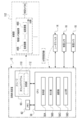
- the server 13 includes a computer 50, an RTC 51, a reception device 52, a display 53, a physical camera communication I / F 54, and a user device communication I / F 56.
- the computer 50 includes a CPU 58, a storage 60, and a memory 62.
- the CPU 58 is an example of a "processor” according to the technique of the present disclosure.
- the memory 62 is an example of a “memory” according to the technique of the present disclosure.
- the computer 50 is an example of a "computer” according to the technique of the present disclosure.
- the CPU 58, the storage 60, and the memory 62 are connected via the bus 64.
- the bus 64 In the example shown in FIG. 4, one bus is shown as the bus 64 for convenience of illustration, but a plurality of buses may be used. Further, the bus 64 may include a serial bus or a parallel bus composed of a data bus, an address bus, a control bus, and the like.
- the CPU 58 controls the entire image processing device 12.
- the storage 60 stores various parameters and various programs.
- the storage 60 is a non-volatile storage device.
- SSD and HDD are applied as an example of the storage 60.
- the memory 62 is a storage device.
- Various information is temporarily stored in the memory 62.
- the memory 62 is used as a work memory by the CPU 58.
- RAM is applied as an example of the memory 62.
- the RTC 51 receives drive power from a power supply system disconnected from the power supply system for the computer 50, and continues to tick the current time (for example, year, month, day, hour, minute, second) even when the computer 50 is shut down.
- the RTC 51 outputs the current time to the CPU 58 each time the current time is updated.
- the CPU 58 uses the current time input from the RTC 51 as the imaging time.
- an example in which the CPU 58 acquires the current time from the RTC 51 is given, but the technique of the present disclosure is not limited to this.
- the CPU 58 is provided from an external device (not shown) via the network 20.
- the current time may be acquired (for example, by using SNMP and / or NTP), or the current time may be acquired from a GNSS device (for example, a GPS device) built in or connected to the computer 50. You may try to do it.
- the reception device 52 receives instructions from the user of the image processing device 12 and the like. Examples of the reception device 52 include a touch panel, hard keys, a mouse, and the like.
- the reception device 52 is connected to a bus 64 or the like, and the instruction received by the reception device 52 is acquired by the CPU 58.
- the display 53 is connected to the bus 64 and displays various information under the control of the CPU 58.
- An example of the display 53 is a liquid crystal display.
- another type of display such as an EL display (for example, an organic EL display or an inorganic EL display) may be adopted as the display 53.
- the communication I / F54 for the physical camera is connected to the antenna 12A.
- the communication I / F 54 for a physical camera is realized, for example, by a device having an FPGA.
- the physical camera communication I / F 54 is connected to the bus 64 and controls the exchange of various information between the CPU 58 and the plurality of physical cameras 16.
- the physical camera communication I / F 54 controls a plurality of physical cameras 16 according to the request of the CPU 58.
- the communication I / F 54 for a physical camera acquires an captured image 46B (see FIG. 2) obtained by being imaged by each of the plurality of physical cameras 16, and outputs the acquired captured image 46B to the CPU 58.
- a wireless communication I / F such as a high-speed wireless LAN is used.
- this is only an example, and may be a wired communication I / F.
- the user device communication I / F 56 is connected to the network 20 so as to be able to wirelessly communicate.
- Communication I / F56 for user devices is realized, for example, by a device having an FPGA.
- the user device communication I / F 56 is connected to the bus 64.
- the user device communication I / F 56 manages the exchange of various information between the CPU 58 and the user device 14 in a wireless communication system via the network 20.
- At least one of the communication I / F54 for the physical camera and the communication I / F56 for the user device can be configured by a fixed circuit instead of the FPGA. Further, at least one of the communication I / F54 for a physical camera and the communication I / F56 for a user device may be a circuit composed of an ASIC, an FPGA, and / or a PLD or the like.
- the television broadcasting device 15 is connected to the bus 64, and the CPU 58 can exchange various information with the television broadcasting device 15 via the bus 64 and grasp the state of the television broadcasting device 15. For example, the CPU 58 can identify the captured image 46B transmitted to the television receiver 18 by the television broadcasting device 15.
- the user device 14 includes a computer 70, an RTC 72, a gyro sensor 74, a reception device 76, a display 78, a microphone 80, a speaker 82, a physical camera 84, and a communication I / F 86.
- the computer 70 includes a CPU 88, a storage 90, and a memory 92, and the CPU 88, the storage 90, and the memory 92 are connected via a bus 94.
- one bus is shown as the bus 94 for convenience of illustration, but the bus 94 may be composed of a serial bus, or may be a data bus, an address bus, a control bus, or the like. Is configured to include.
- the CPU 88 controls the entire user device 14.
- the storage 90 stores various parameters and various programs.
- the storage 90 is a non-volatile storage device.
- EEPROM is applied as an example of the storage 90.
- this is just an example, and may be SSD, HDD, or the like.
- Various information is temporarily stored in the memory 92, and the memory 92 is used as a work memory by the CPU 88.
- RAM is applied as an example of the memory 92.
- the RTC72 receives the drive power from the power supply system disconnected from the power supply system for the computer 70, and keeps ticking the current time (for example, year, month, day, hour, minute, second) even when the computer 70 is shut down.
- the RTC 72 outputs the current time to the CPU 88 every time the current time is updated.
- the CPU 88 can add the current time input from the RTC 72 to the various information transmitted to the image processing device 12.
- the CPU 88 acquires the current time from the RTC 72 is given, but the technique of the present disclosure is not limited to this.
- the CPU 88 is provided from an external device (not shown) via the network 20.
- the current time may be acquired (for example, by using SNMP and / or NTP), or the current time may be acquired from a GNSS device (for example, a GPS device) built in or connected to the computer 70. You may try to do it.
- the gyro sensor 74 includes an angle around the yaw axis of the user device 14 (hereinafter, also referred to as “yaw angle”), an angle around the roll axis of the user device 14 (hereinafter, also referred to as “roll angle”), and the user device 14.
- the angle around the pitch axis (hereinafter, also referred to as “pitch angle”) is measured.
- the gyro sensor 74 is connected to the bus 94, and the angle information indicating the yaw angle, the roll angle, and the pitch angle measured by the gyro sensor 74 is acquired by the CPU 88 via the bus 94 or the like.
- the reception device 76 receives an instruction from the user 22 (see FIGS. 1 and 2). Examples of the reception device 76 include a touch panel 76A, a hard key, and the like. The reception device 76 is connected to the bus 94, and the instruction received by the reception device 76 is acquired by the CPU 88.
- the display 78 is an example of a "display" according to the technique of the present disclosure.
- the display 78 is connected to the bus 94 and displays various information under the control of the CPU 88.
- An example of the display 78 is a liquid crystal display.
- another type of display such as an EL display (for example, an organic EL display or an inorganic EL display) may be adopted as the display 78.
- the user device 14 includes a touch panel display, and the touch panel display is realized by the touch panel 76A and the display 78. That is, the touch panel display is formed by superimposing the touch panel 76A on the display area of the display 78, or by incorporating a touch panel function (“in-cell” type) inside the display 78.
- the "in-cell” type touch panel display is merely an example, and may be an "out-sel” type or "on-cell” type touch panel display.
- the microphone 80 converts the collected sound into an electric signal.
- the microphone 80 is connected to the bus 94.
- the electric signal obtained by converting the sound collected by the microphone 80 is acquired by the CPU 88 via the bus 94.
- the speaker 82 converts an electric signal into sound.
- the speaker 82 is connected to the bus 94.
- the speaker 82 receives the electric signal output from the CPU 88 via the bus 94, converts the received electric signal into sound, and outputs the sound obtained by converting the electric signal to the outside of the user device 14.
- the physical camera 84 acquires an image showing the subject by taking an image of the subject.
- the physical camera 84 is connected to the bus 94.
- the image obtained by capturing the subject by the physical camera 84 is acquired by the CPU 88 via the bus 94.
- the image obtained by the physical camera 84 is also used to generate the virtual viewpoint image 46C together with the captured image 46B. You may be able to do it.
- the communication I / F86 is connected to the network 20 so as to be capable of wireless communication.
- Communication I / F86 is realized, for example, by a device composed of circuits (eg, ASIC, FPGA, and / or PLD, etc.).
- the communication I / F86 is connected to the bus 94.
- the communication I / F86 controls the exchange of various information between the CPU 88 and the external device by a wireless communication method via the network 20.
- Examples of the "external device" include an image processing device 12.
- FIG. 6, 4 obtained by imaging an imaging region (here, as an example, a different region in the soccer field 24A) by four physical cameras 16 out of a plurality of physical cameras 16.
- a kind of physical camera moving image is received by the television receiver 18 as a television image.
- the first physical camera 16A, the second physical camera 16B, the third physical camera 16C, and the fourth physical camera 16D are mentioned.
- four physical cameras 16 are illustrated here for convenience of explanation, the technique of the present disclosure is not limited to this, and the number of physical cameras 16 may be any number.
- Physical camera moving images are roughly classified into 1st to 4th physical camera moving images.
- the first physical camera 16A transmits the moving image of the first physical camera as a television image to the television receiver 18.
- the second physical camera 16B transmits the moving image of the second physical camera as a television image to the television receiver 18.
- the third physical camera 16C transmits the moving image of the third physical camera as a television image to the television receiver 18.
- the fourth physical camera 16D transmits the moving image of the fourth physical camera as a television image to the television receiver 18.
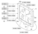
- the television receiver 18 includes a display 100.
- the display 100 has a screen 102, and a physical camera moving image is displayed as a television image on the screen 102.
- the screen 102 on which the moving image of the physical camera is displayed as a television image is an example of "another screen” according to the technique of the present disclosure.
- the physical camera moving image displayed on the screen 102 is an example of the “imaging area image” according to the technique of the present disclosure.
- the screen 102 has a plurality of split screens.
- the screen 102 is divided into four, and the screen 102 has a first divided screen 102A, a second divided screen 102B, a third divided screen 102C, and a fourth divided screen 102D.
- the term "television side split screen" is used. Refer to.
- the first physical camera moving image is displayed on the first split screen 102A.
- the second physical camera moving image is displayed on the second split screen 102B.
- the third physical camera moving image is displayed on the third split screen 102C.
- the fourth physical camera moving image is displayed on the fourth split screen 102D. That is, on the first split screen 102A, the second split screen 102B, the third split screen 102C, and the fourth split screen 102D, each of the four images obtained by capturing images in different imaging methods has a different imaging region. It is displayed individually for each split screen on the TV side.
- the imaging method refers to, for example, an imaging position, an imaging direction, and / or an angle of view.
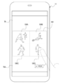
- the screen 102 is imaged by the physical camera 84 of the user device 14.
- the imaging performed here is an imaging for a still image for one frame. However, this is only an example, and imaging for a moving image may be performed.
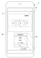
- the display 78 of the user device 14 displays the physical camera moving image screen 104 showing the screen 102 captured as an image in the user device 14.
- the physical camera moving image screen 104 is a still image for one frame showing the screen 102.
- the physical camera moving image screen 104 may be a moving image obtained by taking a moving image with the physical camera 84 of the user device 14 with the screen 102 as a subject. ..
- the physical camera moving image screen 104 is an example of the “imaging area image screen” according to the technique of the present disclosure.
- the physical camera moving image screen 104 has a plurality of split screens.
- the first split screen 104A, the second split screen 104B, the third split screen 104C, and the fourth split screen 104D are mentioned.
- the first split screen 104A, the second split screen 104B, the third split screen 104C, and the fourth split screen 104D are screens obtained by dividing the physical camera moving image screen 104 into four parts.
- a "user device side split screen”. when it is not necessary to distinguish between the first split screen 104A, the second split screen 104B, the third split screen 104C, and the fourth split screen 104D, it is referred to as a "user device side split screen". ..
- a plurality of unique images obtained by capturing images in different imaging methods are displayed on the user device side. It is displayed individually for each split screen.
- the four unique images are images corresponding to the captured image 46B displayed on the first split screen 102A (for example, the captured image 46B included in the first physical camera moving image), and are displayed on the second split screen 102B.
- An image corresponding to the captured image 46B (for example, the captured image 46B included in the second physical camera moving image), and the captured image 46B (for example, included in the third physical camera moving image) displayed on the third divided screen 102C. It refers to an image corresponding to the captured image 46B) and an image corresponding to the captured image 46B displayed on the fourth divided screen 102D (for example, the captured image 46B included in the moving image of the fourth physical camera).
- the first split screen 104A is a screen corresponding to the first split screen 102A.
- the screen corresponding to the first split screen 102A refers to, for example, an image obtained by capturing an image of the first split screen 102A. Therefore, on the first split screen 104A, an image corresponding to the captured image 46B displayed on the first split screen 102A is displayed.
- the second split screen 104B is a screen corresponding to the second split screen 102B.
- the screen corresponding to the second split screen 102B refers to, for example, an image obtained by capturing the second split screen 102B. Therefore, an image corresponding to the captured image 46B displayed on the second split screen 102B is displayed on the second split screen 104B.
- the third split screen 104C is a screen corresponding to the third split screen 102C.
- the screen corresponding to the third split screen 102C refers to, for example, an image obtained by capturing an image of the third split screen 102C. Therefore, an image corresponding to the captured image 46B displayed on the third split screen 102C is displayed on the third split screen 104C.
- the fourth split screen 104D is a screen corresponding to the fourth split screen 102D.
- the screen corresponding to the fourth split screen 102D refers to, for example, an image obtained by capturing the image of the fourth split screen 102D. Therefore, on the fourth split screen 104D, an image corresponding to the captured image 46B displayed on the fourth split screen 102D is displayed.
- the arrangement of the first split screen 104A, the second split screen 104B, the third split screen 104C, and the fourth split screen 104D in the display 78 is the first split screen 102A, the second in the display 100 shown in FIG. It is the same as the arrangement of the split screen 102B, the third split screen 102C, and the fourth split image 102D.
- the user 22 selects one of the user device side split screens via the touch panel 76A, so that the selected user device side split screen is displayed as an image. It is designated as a screen provided to the processing device 12.
- the user device side split screen is designated in this way, as shown in FIG. 9 as an example, a split screen image showing the designated user device side split screen is transmitted by the user device 14 to the image processing device 12. ..
- the fourth split screen 104D is designated by the user 22, and the split screen image showing the fourth split screen 104D is transmitted to the image processing device 12 by the user device 14.
- the split screen image transmitted by the user device 14 in this way is received by the user device communication I / F56 (see FIG. 4) of the image processing device 12.
- the split screen designated by the user 22 is an example of the "specific area” according to the technique of the present disclosure
- the split screen image is an example of the "specific area information" according to the technique of the present disclosure.
- the processing output program 110 and the image group 112 are stored in the storage 60 of the image processing device 12.
- the image group 112 includes all the physical cameras 16 (for example, all installed in the soccer field 24) including the first physical camera 16A, the second physical camera 16B, the third physical camera 16C, and the fourth physical camera 16D. It is configured to include a plurality of physical camera moving images obtained by capturing the imaging region by each of the physical cameras 16). Each of the plurality of physical camera moving images is associated with a physical camera ID capable of identifying the physical camera 16 used for capturing the physical camera moving image.
- the CPU 58 executes the processing output processing (see FIG. 13) described later according to the processing output program 110 stored in the storage 60.
- the CPU 58 reads the processing output program 110 from the storage 60 and executes the processing output program 110 on the memory 62 to operate as the acquisition unit 58A, the processing unit 58B, the search unit 58C, and the output unit 58D.
- the acquisition unit 58A acquires a split screen image showing the user device side split screen specified on the physical camera moving image screen 104.
- the processing unit 58B processes the captured image 46B corresponding to the split screen image acquired by the acquisition unit 58A among the plurality of captured images 46B constituting the plurality of physical camera moving images in the image group 112. Then, the output unit 58D outputs the processed image obtained by processing the captured image 46B by the processing unit 58B.
- the image group 112 is an example of "a plurality of images obtained by capturing an imaging region" according to the technique of the present disclosure.
- the captured image 46B corresponding to the split screen image acquired by the acquisition unit 58A is an example of the "image corresponding to the specific area indicated by the specific area information" according to the technique of the present disclosure.
- the processed image is the position of the "specific area processed image” according to the technique of the present disclosure.
- the split screen image transmitted from the user device 14 to the image processing device 12 is received by the user device communication I / F 56.
- the acquisition unit 58A acquires a split screen image received by the user device communication I / F 56.
- the search unit 58C searches the image group 112 in the storage 60 for the captured image 46B that matches the split screen image acquired by the acquisition unit 58A.
- the captured image 46B that matches the split screen image refers to, for example, the captured image 46B that has the highest degree of coincidence with the split screen image among all the captured images 46B included in the image group 112.
- the captured image 46B that matches the split screen image is also referred to as “same captured image”.
- the processing unit 58B acquires the same captured image from the search unit 58C.
- the processing unit 58B includes a plurality of captured images 46B (which are given the same imaging time as the same captured image acquired from the search unit 58C from the plurality of physical camera moving images in the image group 112. Hereinafter, it is also referred to as "same time image group").
- the processing unit 46 generates a plurality of virtual viewpoint images 46C by using the same captured image acquired from the search unit 58C and the same time image group.
- the same captured image is used to generate the virtual viewpoint image 46C, and in addition, at least one captured image 46B of the same time image group is used.
- the processing unit 46 generates a virtual viewpoint image 46C for each combination pattern. For example, when the same time image group includes the first to third captured images, the processing unit 46 combines the same captured image and the first captured image, the combination of the same captured image and the second captured image, and the same.
- Combination of captured image and third captured image combination of same captured image, first captured image and second captured image, combination of same captured image, first captured image and third captured image, same captured image and first Seven types of virtual viewpoint images 46C are generated by the combination of the two captured images and the third captured image, and the combination of the same captured image and the first to third captured images.
- the output unit 58D outputs a plurality of virtual viewpoint images 46C generated by the processing unit 58B to the user device 14. As a result, at least one of the plurality of virtual viewpoint images 46C is displayed on the display 78 of the user device 14.
- the display 78 of the user device 14 has the same viewpoint as the virtual viewpoint image 46C corresponding to the selected user device side split screen, that is, the physical camera 16 used for imaging to obtain the physical camera moving image.
- a virtual viewpoint image 46C showing an aspect of observing the imaging region in terms of position, line-of-sight direction, and angle of view is displayed.
- the plurality of virtual viewpoint images 46C may be selectively displayed on the display 78 in units of one frame in response to an instruction given to the user device 14 via the touch panel 76A by the user 22. All of the virtual viewpoint images 46C of the above may be displayed in a list in a thumbnail format so as to be selectable.
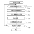
- FIG. 13 shows an example of the flow of machining output processing executed by the CPU 58 according to the machining output program 110.
- the acquisition unit 58A determines whether or not the split screen image has been received by the user device communication I / F56. If the split screen image is not received by the user device communication I / F56 in step ST10, the determination is denied and the processing output process proceeds to step ST20. When the split screen image is received by the user device communication I / F56 in step ST10, the determination is affirmed and the processing output process shifts to step ST12.
- step ST12 the acquisition unit 58A acquires the split screen image received by the communication I / F56 for the user device, and then the processing output process shifts to step ST14.
- step ST14 the search unit 58C searches the image group 112 in the storage 60 for the captured image 46B that matches the split screen image acquired in step ST12, that is, the same captured image, and then the processing output process steps. Move to ST16.
- step ST16 the machining unit 58B executes the machining process shown in FIG. 14 as an example, and then the machining output process shifts to step ST18.
- step ST16A the processing unit 58B has the same imaging time given to the same captured image acquired from the search unit 58C from a plurality of physical camera moving images in the image group 112. A plurality of captured images 46B to which the imaging time of the above is given, that is, the same time image group is acquired, and then the processing output process shifts to step ST16B.
- step ST16B the processing unit 58B generates a plurality of virtual viewpoint images 46C based on the same captured image searched in step ST14 and the same time image group acquired in step ST16A, and then processing is performed. finish.
- step ST18 shown in FIG. 13 the output unit 58D outputs the plurality of virtual viewpoint images 46C generated in step ST16B to the user device 14. As a result, at least one of the plurality of virtual viewpoint images 46C is displayed on the display 78 of the user device 14. After the process of step ST18 is executed, the machining output process shifts to step ST20.
- step ST20 the output unit 58D determines whether or not the condition for terminating the machining output process (hereinafter, also referred to as “machining output process end condition”) is satisfied.
- the processing output processing end condition there is a condition that the image processing apparatus 12 is instructed to end the processing output processing.
- the instruction to end the processing output process is received by, for example, the receiving device 52 or 76. If the processing output processing end condition is not satisfied in step ST20, the determination is denied and the processing output processing shifts to step ST10. If the processing output processing end condition is satisfied in step ST20, the determination is affirmed and the processing output processing ends.
- the split screen image showing the split screen on the user device side designated by the user 22 when the split screen image showing the split screen on the user device side designated by the user 22 is acquired by the acquisition unit 58A, it corresponds to the split screen image acquired by the acquisition unit 58A.
- the same captured image is processed by the processing unit 58B to generate a virtual viewpoint image 46C. Therefore, according to this configuration, among the plurality of captured images 46B included in the physical camera moving image, the virtual viewpoint image 46C processed by processing the captured image 46B designated by the user 22 by selecting the split screen on the user device side. Can be viewed by the user 22.
- any one of the plurality of captured images 46B is designated by the user 22 is given, but the technique of the present disclosure is not limited to this, and a person other than the user 22 (for example, soccer commentary). Person, etc.) may specify the captured image 46B to be processed.
- the physical camera moving image may be a live broadcast image.
- the user 22 is allowed to view the virtual viewpoint image 46C processed by the captured image 46B designated by the user 22 selecting the split screen on the user device side. be able to.
- the physical camera moving image may be an image including a live broadcast image.
- An example of an image including a live broadcast video is a video including a live broadcast video and a replay video.
- the physical camera 84 of the user device 14 captures the screen 102 of the television receiver 18, so that the physical camera moving image screen 104 is displayed on the display 78 of the user device 14. There is. Therefore, according to this configuration, even in a situation where the television image is not directly provided to the user device 14 from the television broadcasting device 15, the processing target is processed from the physical camera moving image as the television image to the user 22. It is possible to specify the captured image 46B.
- the captured image to be processed is selected by the user 22 from the plurality of user device side split screens included in the physical camera moving image screen 104. 46B is specified. Therefore, according to this configuration, the user 22 can specify the captured image 46B to be processed for each split screen on the user device side.
- the first split screen 104A, the second split screen 104B, the third split screen 104C, and the fourth split screen 104D were obtained by taking images in different imaging methods.
- a plurality of unique images are individually displayed for each split screen on the user device side. Therefore, according to this configuration, the user 22 can select any of the first split screen 104A, the second split screen 104B, the third split screen 104C, and the fourth split screen 104D on the user device side.
- Any one of the plurality of captured images 46B obtained by capturing images by different imaging methods can be designated as the captured image 46B.
- the virtual viewpoint image 46C generated by the processing unit 58B is output to the user device 14 by the output unit 58D, so that the virtual viewpoint image 46C is displayed on the display 78 of the user device 14. I have to. Therefore, according to this configuration, among the plurality of captured images 46B included in the moving image of the physical camera, the virtual viewpoint image 46C is processed by processing the captured image 46B designated by the user 22 by selecting the split screen on the user device side. Can be viewed by the user 22 via the display 78 of the user device 14.
- a plurality of physical camera moving images obtained by being imaged by different imaging methods are displayed in parallel on the display 100 of the television receiver 18, so that the entire screen 102 is contained in one frame.
- the present invention has been described with reference to an example in which the screen 102 is imaged by the physical camera 84 of the user device 14, but the technique of the present disclosure is not limited to this.
- the technique of the present disclosure is not limited to this.
- only the physical camera moving image obtained by being imaged by any one of the plurality of physical cameras 16 is displayed on the screen 102, and the entire screen 102 is displayed on the user device 14.
- the image may be taken by the physical camera 84 so as to fit in one frame.
- the physical camera moving image screen 104 is divided into a plurality of areas and displayed.
- a screen showing the captured image 46B for one frame is displayed on the display 78.
- the mode in which the physical camera moving image screen 104 is divided into four by the first split screen 104A, the second split screen 104B, the third split screen 104C, and the fourth split screen 104D is shown. ing.
- the user device side split screen of any one of the first split screen 104A, the second split screen 104B, the third split screen 104C, and the fourth split screen 104D is set by the user 22. Be selected. Then, the split screen image showing the split screen on the user device side selected by the user 22 is transmitted by the user device 14 to the image processing device 12. In this case, a part of the captured image 46B for one frame is targeted for processing by the processing unit 58B, and the processing output process is executed in the same manner as in the above embodiment.
- an image for example, a virtual viewpoint image 46C
- the user 22 selects a part of the captured image 46B for one frame by selecting any of the first split screen 104A, the second split screen 104B, the third split screen 104C, and the fourth split screen 104D.
- the physical camera moving image screen 104 is divided into a plurality of areas and displayed, but the technique of the present disclosure is not limited to this, and the physical camera moving image screen 104 is displayed. It may be displayed on the display 78 of the user device 14 as it is as a single screen without being divided.
- one frame of still image is displayed on the physical camera moving image screen 104, but the technique of the present disclosure is not limited to this.
- the frame-by-frame moving image may be displayed on the display 78.
- the screen 102 on which the physical camera moving image is displayed is set as the subject
- the physical camera 84 of the user device 14 takes an image for the moving image
- the moving image showing the screen 102 is displayed on the user device 14. Make it captured.
- a still image for one frame of the moving image obtained by capturing the screen 102 by the physical camera 84 of the user device 14 (for example, a still image of the first frame). Is divided and displayed on the first split screen 104A, the second split screen 104B, the third split screen 104C, and the fourth split screen 104D.
- the user 22 selects one of the first split screen 104A, the second split screen 104B, the third split screen 104C, and the fourth split screen 104D via the touch panel 76A.
- the user selected by the user 22 in the display area of the display 78 which is different from the physical camera moving image screen 104.
- a frame-by-frame moving image related to the device-side split screen is displayed.
- a split screen image showing the selected frame is transmitted to the image processing device 12 by the user device 14.
- the user 22 specifies an unintended split screen on the user device side, as compared with the case where a moving image having a higher frame rate than the frame-advancing moving image is displayed. Therefore, compared to the case where the user device side split screen is specified by the user 22 from the moving image in the state where the moving image having a higher frame rate than the frame-advancing moving image is displayed, the virtual based on the captured image 46B not intended by the user 22. It is possible to reduce the possibility that the viewpoint image 46C is generated by the processing unit 58B.
- a frame-by-frame moving image related to the split screen on the user device side selected by the user 22 is displayed on the display 78, but the technique of the present disclosure is not limited to this. ..
- the entire or a part of the physical camera moving image screen 104 may be displayed as a frame-by-frame moving image.
- the technique is not limited to this in the present disclosure.
- one of the imaging scenes is selected by the user 22 from a menu screen capable of identifying a plurality of imaging scenes in which at least one of the imaging position, the imaging direction, and the angle of view at which imaging is performed with respect to the imaging region is different. By doing so, the captured image 46B to be processed may be designated.
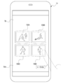
- the menu screen 106 is displayed on the display 78 in a display area different from that of the physical camera moving image screen 104.
- the menu screen 106 is an item indicating what kind of imaging scene each of the images displayed on the first split screen 104A, the second split screen 104B, the third split screen 104C, and the fourth split screen 104D is. Is shown for each split screen on the user device side.
- the user 22 selects any item from the menu screen via the touch panel 76A.
- the split screen image showing the split screen on the user device side corresponding to the item selected by the user 22 is transmitted from the user device 14 to the image processing device 12, and the captured image 46B corresponding to the split screen image is transferred to the processing unit 58B. It is subject to processing by.
- the user device 22 corresponds to an imaging scene intended by the user 22 among a plurality of imaging scenes in which at least one of the imaging position, the imaging direction, and the angle of view at which imaging is performed with respect to the imaging region is different.
- the user device 22 can be made to specify the split screen on the user device side.
- the user device side split screen is selected by the user 22 to specify the captured image 46B to be processed.
- a region corresponding to an object selected from object identification information capable of identifying a plurality of objects included in the imaging region may be designated as a processing target by the processing unit 58B.
- an object selection screen is displayed on the display 78 in a display area different from that of the physical camera moving image screen 104. 108 is displayed.
- object identification information capable of identifying an object (for example, a player name, a soccer field, a ball, etc.) existing in the soccer field 24A is shown so as to be selectable for each object.
- the object identification information selected by the user device 14 and the time when the object selection information is selected (hereinafter, also referred to as “selection time”) are set. It is transmitted to the image processing device 12.
- the processing unit 58B assigns the same imaging time as the selection time from the image group 112 and based on a plurality of captured images 46B including an object specified by the object identification information.
- One virtual viewpoint image 46C is generated.
- the object identification information shown on the object selection screen 108 may be registered in advance in the user device 14 or may be provided by the image processing device 12.
- the object identification information is provided from the image processing device 12
- a QR code (registered trademark) or the like that encrypts the object selection screen 108 is displayed on the display 100 or the like of the television receiver 18, and the QR code is imaged by the physical camera 84 of the user device 14.
- the object selection screen 108 is captured in the user device 14.
- the user 22 intends to specify the region corresponding to the object selected from the object identification information that can identify a plurality of objects included in the imaging region as the processing target by the processing unit 58B.
- the captured image 46B related to the object to be processed can be processed by the processing unit 58B.
- the split screen image is transmitted to the image processing device 12 by the user device 14, but the technique of the present disclosure is not limited to this.
- the screen number and the television screen capture time may be transmitted to the image processing device 12 by the user device 14.
- the screen number is a number that can identify any of the user device-side split screens in the physical camera moving image screen 104.
- the screen number is received by, for example, the receiving device 76.
- the TV screen capture time refers to the time when the screen 102 is captured in the user device 14.
- the time when the screen 102 is captured by the user device 14 the time when the image is taken by the physical camera 84 of the user device 14, the time when the physical camera moving image screen 104 is generated by the user device 14, or the physical time.
- the time when the camera moving image screen 104 is displayed on the display 78 of the user device 14 can be mentioned.
- the screen number and the TV screen capture time are transmitted to the image processing device 12 by the user device 14, the screen number and the TV screen capture time are received by the user device communication I / F 56 as shown in FIG. 21 as an example. Will be done.
- the screen number and the TV screen capture time received by the user device communication I / F 56 are acquired by the acquisition unit 58A.
- the storage 60 stores a correspondence table 114 in which the screen number and the physical camera ID are associated with each other.
- a physical camera ID is associated with the screen number for each of the first physical camera 16A, the second physical camera 16B, the third physical camera 16C, and the fourth physical camera 16D.
- the physical camera ID of the first physical camera 16A with respect to the screen number is updated by the CPU 58 to the changed physical camera ID of the physical camera 16.
- the physical camera ID of the second physical camera 16B with respect to the screen number is updated by the CPU 58 to the changed physical camera ID of the physical camera 16.
- the third physical camera 16C is changed to another physical camera
- the physical camera ID of the third physical camera 16C with respect to the screen number is updated by the CPU 58 to the changed physical camera ID of the physical camera 16.
- the fourth physical camera 16D is changed to another physical camera, the physical camera ID of the fourth physical camera 16D with respect to the screen number is updated by the CPU 58 to the changed physical camera ID of the physical camera 16. ..
- the moving image of the first physical camera displayed on the first split screen 102A is obtained by being captured by the new first physical camera 16A. Switch to physical camera moving image.
- the second physical camera 16B is changed to another physical camera 16
- the second physical camera moving image displayed on the second split screen 102B is obtained by being captured by the new second physical camera 16B.
- the third physical camera 16C is changed to another physical camera 16
- the moving image of the third physical camera displayed on the third split screen 102C is obtained by being captured by the new third physical camera 16C. Switch to physical camera moving image.
- the 4th physical camera moving image displayed on the 4th split screen 102D is obtained by being captured by the new 4th physical camera 16D. Switch to physical camera moving image. In this way, when the physical camera moving image displayed on the TV-side split screen is switched, the image displayed on the user device-side split screen is also switched. Then, the physical camera ID associated with the screen number in the corresponding table 114 is also updated so as to correspond to this.
- the search unit 58C identifies the physical camera ID corresponding to the screen number acquired by the acquisition unit 58A.
- the search unit 58C identifies a physical camera moving image associated with the specified physical camera ID. Then, the search unit 58C searches for the captured image 46B, that is, the same captured image, which is given the same imaging time as the television screen capture time acquired by the acquisition unit 58A from the specified physical camera moving image.
- the captured image 46B designated by the user 22 is processed by the processing unit 58B with reference to an example, but the processed contents of the captured image 46B are processed according to an instruction given from the outside. It may be changed by the processing unit 58B.
- the processing content instruction information for instructing the processing content is received by the touch panel 76A of the user device 14
- the processing content instruction information is output to the processing unit 58 by the user device 14.
- the processing content instruction information there is a person emphasis instruction information for instructing the emphasis of a person. In the example shown in FIG.
- the person reflected in the virtual viewpoint image 46C is emphasized by processing the virtual viewpoint image 46C to make the person image showing the person higher than the resolution around the person image.
- the method of emphasizing the person reflected in the virtual viewpoint image 46C is not limited to this, and the outline of the person image in the virtual viewpoint image 46C may be highlighted. Further, at least a part of the brightness in the virtual viewpoint image 46C may be changed, or colors, characters, / images and the like specified by the user 22 may be superimposed on the virtual viewpoint image 46C.
- the processing content of the captured image 46B is changed by the processing unit 58B in response to an instruction given from the outside, so that the virtual viewpoint image 46C can be finished to the processing content intended by the user 22. ..
- the virtual viewpoint image 46C is the target for changing the processing content, but the technique of the present disclosure is not limited to this, and the captured image 46B is a processed image other than the virtual viewpoint image 46C.
- the image may be subject to change in the processing content.
- An image other than the virtual viewpoint image 46C is obtained by subjecting, for example, a process of increasing the resolution of the central portion or a person image of the captured image 46B obtained by being captured by the physical camera 16 to be higher than the resolution of other regions. Refers to the image that was created.
- the processing content instruction information information for instructing the change of the resolution of the central portion or the person image of the captured image 46B and / or the resolution of the other region can be mentioned.
- the physical camera moving image screen 104 may be a live view image. That is, the physical camera 84 of the user device 14 captures the live view image on the screen 102 in which the physical camera moving image is displayed as a television image.
- the live view image obtained by capturing the first split screen 102A in which the first physical camera moving image is displayed as a television image by the physical camera 84 is displayed on the first split screen 104A. ..
- a live view image obtained by capturing the second split screen 102B in which the second physical camera moving image is displayed as a television image by the physical camera 84 is displayed.
- a live view image obtained by capturing the third split screen 102C in which the third physical camera moving image is displayed as a television image by the physical camera 84 is displayed.
- the fourth split screen 104D displays a live view image obtained by capturing the fourth split screen 102D in which the fourth physical camera moving image is displayed as a television image by the physical camera 84.
- the captured image 46B corresponding to the frame displayed on the user device side split screen at the selected timing is produced by the processing unit 58B. Designated as a processing target. Then, the processing unit 58B generates a virtual viewpoint image 46C based on the designated captured image 46B, and the output unit 58D outputs the virtual viewpoint image 46C generated by the processing unit 58B to the user device 14. That is, the CPU 58 generates and outputs the virtual viewpoint image 46C with reference to the designated timing of the captured image 46B.
- the virtual viewpoint image 46C generated at a timing closer to the timing intended by the user 22 is compared with the case where the virtual viewpoint image 46C is generated without considering the timing when the captured image 46B is specified. It can be provided to the user 22.
- the virtual viewpoint image 46C is exemplified as the processed image of the captured image 46B, but the technique of the present disclosure is not limited to this, and the captured image 46B specified by the user 22 is processed by the processing unit 58B. If it is a processed image, it may be an image other than the virtual viewpoint image 46C.
- the technique of the present disclosure is not limited to this, and the physical camera moving image is displayed on the user device 14. It may be displayed directly as a TV image. In this case, it is not necessary to capture the screen 102 in the user device 14.
- the physical camera moving image obtained by being captured by any one of the plurality of physical cameras 16 may be displayed on the user device 14, or may be captured by the plurality of physical cameras 16.
- the plurality of physical camera moving images obtained by the above may be displayed on the display 78 of the user device 14. Further, when the physical camera moving image is directly displayed on the display 78 of the user device 14, the moving image may be paused at a timing intended by the user 22. This makes it easy for the user 22 to generate a virtual viewpoint image corresponding to the target image.
- the example in which the screen 102 is divided into four is described, but this is only an example, and the number of divisions of the screen 102 may be any number.
- the display 100 includes a plurality of split screens on the TV side
- the split screens on the TV side are divided into a plurality of displays and displayed. May be good. That is, at least one of the plurality of split screens on the television side may be displayed on another display.
- the first split screen 102A, the second split screen 102B, the third split screen 102C, and the fourth split screen 102D may be displayed one by one on separate displays.
- the screen 150A1 is displayed on the display 150A of the television receiver 150
- the screen 152A1 is displayed on the display 152A of the television receiver 152
- the screen 154A1 is displayed on the display 154A of the television receiver 154.
- the screen 156A1 may be displayed on the display 156A of the television receiver 156.
- the screen 150A1 displays the first physical camera moving image as in the first split screen 102A described in the above embodiment
- the screen 152A1 displays the second split screen described in the above embodiment.
- the second physical camera moving image is displayed
- the screen 154A1 displays the third physical camera moving image as in the third split screen 102C described in the above embodiment
- the screen 156A1 displays the moving image of the third physical camera.
- the fourth physical camera moving image may be displayed.
- the screens 150A1, 152A1, 154A1 and 156A1 may be imaged by the physical camera 84 of the user device 14, as in the above embodiment. That is, in this case, the screens of the four television receivers exist in the imaging region of the physical camera 84.
- the display 78 of the user device 14 displays the screens 158A and 152A1 which are images showing the screen 150A1.
- the screen 158B, which is an image to be shown, the screen 158C, which is an image showing the screen 154A1, and the screen 158D, which is an image showing the screen 156A1, are displayed.
- the screen 158A is a screen corresponding to the first split screen 104A described in the above embodiment
- the screen 158B is a screen corresponding to the second split screen 104B described in the above embodiment
- the screen 158C is the screen corresponding to the above-described embodiment. It is a screen corresponding to the third split screen 104C described in the embodiment
- the screen 158D is a screen corresponding to the fourth split screen 104D described in the above embodiment.
- the television receivers 150, 152, 154 and 156 are attached to the board 157
- the installation embodiments of the television receivers 150, 152, 154 and 156 and The number of installations is not limited to this.
- at least one of the television receivers 150, 152, 154 and 156 may be a stand-type television receiver, a hanging television receiver, or a cantilever television receiver, or may be installed. The number may be any number.
- the technique of the present disclosure is not limited to this, and for example, as shown in FIG. 26, it is connected to the display 160A of the tablet terminal 160 and the personal computer 162.
- Display 164 may be used.
- the physical camera moving image is displayed on each of the screen 160A1 of the display 160A and the screen 164A1 of the display 164A.
- the screens 150A1, 152A1, 154A1, 156A1, 160A1 and 164A1 may be imaged by the physical camera 84 of the user device 14.
- the desktop type personal computer 162 is illustrated, but the present invention is not limited to this, and a notebook type personal computer may be used.
- the screen 160A1 of the display 160A of the tablet terminal 160 and the screen 164A1 of the display 164A connected to the personal computer 162 were illustrated, but they were projected by the screen of the display of the smartphone and / or the projector. It may be a screen formed by another type of device such as a screen. Further, the technique of the present disclosure is not limited to the screen on which the moving image of the physical camera is displayed, and the processed image obtained by processing the image obtained by capturing the image (for example, a virtual viewpoint). The screen may be a screen on which an image) is displayed.
- the physical camera moving image screen 104 is a still image
- the present invention is not limited to this, and the physical camera moving image screen 104 may be a moving image.
- the image intended by the user 22 is The user 22 may perform a flick operation, a swipe operation, / or a tap operation, or the like on the touch panel 76A so that the touch panel 76A is selectively displayed on the display 78.
- the physical camera moving image obtained by being captured by the physical camera 16 has been described with reference to a form example in which the moving image is displayed on the screen 102, but the technique of the present disclosure is not limited to this.
- a virtual viewpoint moving image composed of a plurality of virtual viewpoint images 46C obtained by being imaged by the virtual camera 42 may be displayed on the screen 102.
- the physical camera moving image and the virtual viewpoint moving image may be displayed on the screen 102 on separate split screens.
- the image is not limited to a moving image, and may be a still image or a continuous shooting image.
- the soccer stadium 24 is illustrated, but this is only an example, and is a baseball stadium, a rugby stadium, a curling stadium, an athletic stadium, a swimming pool, a concert hall, an outdoor music stadium, and a theater venue.
- the place may be any place.
- computers 50 and 70 have been exemplified, but the technique of the present disclosure is not limited to this.
- devices including ASICs, FPGAs, and / or PLDs may be applied.
- the computer 50 and / or 70 a combination of hardware configuration and software configuration may be used.
- processing output processing is executed by the CPU 58 of the image processing apparatus 12
- the technique of the present disclosure is not limited to this.
- a part of the processing included in the processing output processing may be executed by the CPU 88 of the user device 14.
- a GPU may be adopted, or a plurality of CPUs may be adopted, so that various processes are executed by one processor or a plurality of physically separated processors. You may.
- the processing output program 110 is stored in the storage 60, but the technique of the present disclosure is not limited to this, and as shown in FIG. 27 as an example, an arbitrary portable storage medium 200 is used.
- the processing output program 110 may be stored.
- the storage medium 200 is a non-temporary storage medium. Examples of the storage medium 200 include SSD and USB memory.
- the processing output program 110 stored in the storage medium 200 is installed in the computer 50, and the CPU 58 executes the processing output processing according to the processing output program 110.
- processing output program 110 is stored in the program memory of another computer or server device connected to the computer 50 via the communication network (not shown), and the processing output program is stored in response to the request of the image processing device 12.
- the 110 may be downloaded to the image processing device 12.
- the processing output process based on the downloaded processing output program 110 is executed by the CPU 58 of the computer 50.
- processors can be used as hardware resources for executing processing output processing.
- Examples of the processor include, as described above, software, that is, a CPU, which is a general-purpose processor that functions as a hardware resource for executing processing output processing according to a program.
- a dedicated electric circuit which is a processor having a circuit configuration specially designed for executing a specific process such as FPGA, PLD, or ASIC can be mentioned.
- a memory is built in or connected to each processor, and each processor executes processing output processing by using the memory.
- the hardware resource that executes the processing output processing may be composed of one of these various processors, or a combination of two or more processors of the same type or different types (for example, a combination of a plurality of FPGAs, or a combination of a plurality of FPGAs). It may be composed of a combination of a CPU and an FPGA). Further, the hardware resource for executing the processing output processing may be one processor.
- one processor is configured by a combination of one or more CPUs and software, and this processor is used for processing output.
- this processor is used for processing output.
- SoC there is a form in which a processor that realizes the functions of the entire system including a plurality of hardware resources for executing processing output processing with one IC chip is used.
- the processing output processing is realized by using one or more of the above-mentioned various processors as a hardware resource.
- processing output processing is just an example. Therefore, it goes without saying that unnecessary steps may be deleted, new steps may be added, or the processing order may be changed within a range that does not deviate from the purpose.
- a and / or B is synonymous with "at least one of A and B". That is, “A and / or B” means that it may be only A, only B, or a combination of A and B. Further, in the present specification, when three or more matters are connected and expressed by "and / or", the same concept as “A and / or B" is applied.
Landscapes
- Engineering & Computer Science (AREA)
- Multimedia (AREA)
- Signal Processing (AREA)
- Human Computer Interaction (AREA)
- Databases & Information Systems (AREA)
- Computer Security & Cryptography (AREA)
- Computer Graphics (AREA)
- Studio Devices (AREA)
Priority Applications (2)
| Application Number | Priority Date | Filing Date | Title |
|---|---|---|---|
| JP2022517663A JPWO2021220893A1 (https=) | 2020-04-28 | 2021-04-20 | |
| US18/049,637 US20230085590A1 (en) | 2020-04-28 | 2022-10-26 | Image processing apparatus, image processing method, and program |
Applications Claiming Priority (2)
| Application Number | Priority Date | Filing Date | Title |
|---|---|---|---|
| JP2020-079535 | 2020-04-28 | ||
| JP2020079535 | 2020-04-28 |
Related Child Applications (1)
| Application Number | Title | Priority Date | Filing Date |
|---|---|---|---|
| US18/049,637 Continuation US20230085590A1 (en) | 2020-04-28 | 2022-10-26 | Image processing apparatus, image processing method, and program |
Publications (1)
| Publication Number | Publication Date |
|---|---|
| WO2021220893A1 true WO2021220893A1 (ja) | 2021-11-04 |
Family
ID=78373564
Family Applications (1)
| Application Number | Title | Priority Date | Filing Date |
|---|---|---|---|
| PCT/JP2021/016071 Ceased WO2021220893A1 (ja) | 2020-04-28 | 2021-04-20 | 画像処理装置、画像処理方法、及びプログラム |
Country Status (3)
| Country | Link |
|---|---|
| US (1) | US20230085590A1 (https=) |
| JP (1) | JPWO2021220893A1 (https=) |
| WO (1) | WO2021220893A1 (https=) |
Families Citing this family (2)
| Publication number | Priority date | Publication date | Assignee | Title |
|---|---|---|---|---|
| US12519924B2 (en) * | 2022-08-31 | 2026-01-06 | Snap Inc. | Multi-perspective augmented reality experience |
| EP4443273A1 (en) * | 2023-03-31 | 2024-10-09 | Canon Kabushiki Kaisha | Display control apparatus, display control method, and program |
Citations (3)
| Publication number | Priority date | Publication date | Assignee | Title |
|---|---|---|---|---|
| JP2006013923A (ja) * | 2004-06-25 | 2006-01-12 | Sony Corp | 監視装置 |
| JP2008028876A (ja) * | 2006-07-25 | 2008-02-07 | Hitachi Ltd | 多分割画面表示装置 |
| JP2018207336A (ja) * | 2017-06-06 | 2018-12-27 | キヤノン株式会社 | 情報処理装置、情報処理システム、情報処理方法及びプログラム |
Family Cites Families (1)
| Publication number | Priority date | Publication date | Assignee | Title |
|---|---|---|---|---|
| WO2015193977A1 (ja) * | 2014-06-17 | 2015-12-23 | 株式会社東芝 | 電子機器、方法、及びプログラム |
-
2021
- 2021-04-20 JP JP2022517663A patent/JPWO2021220893A1/ja active Pending
- 2021-04-20 WO PCT/JP2021/016071 patent/WO2021220893A1/ja not_active Ceased
-
2022
- 2022-10-26 US US18/049,637 patent/US20230085590A1/en not_active Abandoned
Patent Citations (3)
| Publication number | Priority date | Publication date | Assignee | Title |
|---|---|---|---|---|
| JP2006013923A (ja) * | 2004-06-25 | 2006-01-12 | Sony Corp | 監視装置 |
| JP2008028876A (ja) * | 2006-07-25 | 2008-02-07 | Hitachi Ltd | 多分割画面表示装置 |
| JP2018207336A (ja) * | 2017-06-06 | 2018-12-27 | キヤノン株式会社 | 情報処理装置、情報処理システム、情報処理方法及びプログラム |
Also Published As
| Publication number | Publication date |
|---|---|
| JPWO2021220893A1 (https=) | 2021-11-04 |
| US20230085590A1 (en) | 2023-03-16 |
Similar Documents
| Publication | Publication Date | Title |
|---|---|---|
| JP6907861B2 (ja) | 通信端末、画像通信システム、表示方法、及びプログラム | |
| EP3301909B1 (en) | Communication management apparatus, communication system, communication management method, and carrier means | |
| EP3346702B1 (en) | Communication terminal, image communication system, communication method, and carrier means | |
| US11102448B2 (en) | Image capturing apparatus, image processing system, image processing method, and recording medium | |
| EP3712839A1 (en) | Image capturing device, image capturing system, image processing method, and carrier means | |
| US11743590B2 (en) | Communication terminal, image communication system, and method for displaying image | |
| EP3989539B1 (en) | Communication management apparatus, image communication system, communication management method, and carrier means | |
| US12112425B2 (en) | Information processing apparatus, method of operating information processing apparatus, and program for generating virtual viewpoint image | |
| JP2009294689A (ja) | 移動端末装置およびその制御方法、制御プログラム、コンピュータ読み取り可能な記録媒体ならびにマルチディスプレイシステム | |
| EP3962090A1 (en) | Communication terminal, image communication system, method for displaying image, and carrier means | |
| EP4099705A1 (en) | Communication terminal, image communication system, method for displaying image, and carrier means | |
| US10609259B2 (en) | Image displaying system, communication system, and method for image displaying | |
| EP4064691A1 (en) | Communication management device, image communication system, communication management method, and carrier means | |
| US20230071355A1 (en) | Image processing apparatus, image processing method, and program | |
| US20230085590A1 (en) | Image processing apparatus, image processing method, and program | |
| US20230419596A1 (en) | Image processing apparatus, image processing method, and program | |
| WO2022024594A1 (ja) | 情報処理装置、情報処理方法、及びプログラム | |
| US12143674B2 (en) | Information processing apparatus, information processing method, and program | |
| WO2022209361A1 (ja) | 画像処理装置、画像処理方法、及びプログラム | |
| JP2018061243A (ja) | 通信端末、表示方法、及びプログラム | |
| EP4436190A1 (en) | Display terminal, communication system, and method for displaying | |
| US20250292489A1 (en) | Information processing apparatus, screen generation method, non-transitory recording medium, and information processing system | |
| US20250278173A1 (en) | Display terminal, display method, and non-transitory recording medium | |
| US20250335141A1 (en) | Information processing apparatus, information processing system, screen generating method, and recording medium | |
| US20250272907A1 (en) | Information processing apparatus, information processing system, screen generation method, and recording medium |
Legal Events
| Date | Code | Title | Description |
|---|---|---|---|
| 121 | Ep: the epo has been informed by wipo that ep was designated in this application |
Ref document number: 21796402 Country of ref document: EP Kind code of ref document: A1 |
|
| ENP | Entry into the national phase |
Ref document number: 2022517663 Country of ref document: JP Kind code of ref document: A |
|
| NENP | Non-entry into the national phase |
Ref country code: DE |
|
| 122 | Ep: pct application non-entry in european phase |
Ref document number: 21796402 Country of ref document: EP Kind code of ref document: A1 |