WO2021215224A1 - Paire de composants coulissants - Google Patents
Paire de composants coulissants Download PDFInfo
- Publication number
- WO2021215224A1 WO2021215224A1 PCT/JP2021/014347 JP2021014347W WO2021215224A1 WO 2021215224 A1 WO2021215224 A1 WO 2021215224A1 JP 2021014347 W JP2021014347 W JP 2021014347W WO 2021215224 A1 WO2021215224 A1 WO 2021215224A1
- Authority
- WO
- WIPO (PCT)
- Prior art keywords
- positive pressure
- pressure generating
- generating groove
- sliding
- groove
- Prior art date
Links
- 239000012530 fluid Substances 0.000 claims abstract description 47
- 238000007789 sealing Methods 0.000 claims description 109
- 230000003068 static effect Effects 0.000 claims description 48
- OKTJSMMVPCPJKN-UHFFFAOYSA-N Carbon Chemical compound [C] OKTJSMMVPCPJKN-UHFFFAOYSA-N 0.000 description 9
- 239000000463 material Substances 0.000 description 9
- 230000001154 acute effect Effects 0.000 description 7
- 229910052799 carbon Inorganic materials 0.000 description 7
- 239000007788 liquid Substances 0.000 description 6
- 230000004048 modification Effects 0.000 description 3
- 238000012986 modification Methods 0.000 description 3
- 238000000926 separation method Methods 0.000 description 3
- 238000010008 shearing Methods 0.000 description 3
- 229910002804 graphite Inorganic materials 0.000 description 2
- 239000010439 graphite Substances 0.000 description 2
- 239000000203 mixture Substances 0.000 description 2
- 230000002093 peripheral effect Effects 0.000 description 2
- 230000007704 transition Effects 0.000 description 2
- 238000011144 upstream manufacturing Methods 0.000 description 2
- ZOXJGFHDIHLPTG-UHFFFAOYSA-N Boron Chemical compound [B] ZOXJGFHDIHLPTG-UHFFFAOYSA-N 0.000 description 1
- 238000007792 addition Methods 0.000 description 1
- 229910052782 aluminium Inorganic materials 0.000 description 1
- XAGFODPZIPBFFR-UHFFFAOYSA-N aluminium Chemical compound [Al] XAGFODPZIPBFFR-UHFFFAOYSA-N 0.000 description 1
- 229910052796 boron Inorganic materials 0.000 description 1
- 239000011248 coating agent Substances 0.000 description 1
- 238000000576 coating method Methods 0.000 description 1
- 238000004891 communication Methods 0.000 description 1
- 239000002131 composite material Substances 0.000 description 1
- 230000007613 environmental effect Effects 0.000 description 1
- 239000007769 metal material Substances 0.000 description 1
- 239000003595 mist Substances 0.000 description 1
- 239000002245 particle Substances 0.000 description 1
- 239000011347 resin Substances 0.000 description 1
- 229920005989 resin Polymers 0.000 description 1
- 238000005245 sintering Methods 0.000 description 1
- 239000007779 soft material Substances 0.000 description 1
- XLYOFNOQVPJJNP-UHFFFAOYSA-N water Substances O XLYOFNOQVPJJNP-UHFFFAOYSA-N 0.000 description 1
Images


Classifications
-
- F—MECHANICAL ENGINEERING; LIGHTING; HEATING; WEAPONS; BLASTING
- F16—ENGINEERING ELEMENTS AND UNITS; GENERAL MEASURES FOR PRODUCING AND MAINTAINING EFFECTIVE FUNCTIONING OF MACHINES OR INSTALLATIONS; THERMAL INSULATION IN GENERAL
- F16C—SHAFTS; FLEXIBLE SHAFTS; ELEMENTS OR CRANKSHAFT MECHANISMS; ROTARY BODIES OTHER THAN GEARING ELEMENTS; BEARINGS
- F16C17/00—Sliding-contact bearings for exclusively rotary movement
- F16C17/04—Sliding-contact bearings for exclusively rotary movement for axial load only
-
- F—MECHANICAL ENGINEERING; LIGHTING; HEATING; WEAPONS; BLASTING
- F16—ENGINEERING ELEMENTS AND UNITS; GENERAL MEASURES FOR PRODUCING AND MAINTAINING EFFECTIVE FUNCTIONING OF MACHINES OR INSTALLATIONS; THERMAL INSULATION IN GENERAL
- F16J—PISTONS; CYLINDERS; SEALINGS
- F16J15/00—Sealings
- F16J15/16—Sealings between relatively-moving surfaces
- F16J15/34—Sealings between relatively-moving surfaces with slip-ring pressed against a more or less radial face on one member
- F16J15/3404—Sealings between relatively-moving surfaces with slip-ring pressed against a more or less radial face on one member and characterised by parts or details relating to lubrication, cooling or venting of the seal
- F16J15/3408—Sealings between relatively-moving surfaces with slip-ring pressed against a more or less radial face on one member and characterised by parts or details relating to lubrication, cooling or venting of the seal at least one ring having an uneven slipping surface
- F16J15/3424—Sealings between relatively-moving surfaces with slip-ring pressed against a more or less radial face on one member and characterised by parts or details relating to lubrication, cooling or venting of the seal at least one ring having an uneven slipping surface with microcavities
-
- F—MECHANICAL ENGINEERING; LIGHTING; HEATING; WEAPONS; BLASTING
- F16—ENGINEERING ELEMENTS AND UNITS; GENERAL MEASURES FOR PRODUCING AND MAINTAINING EFFECTIVE FUNCTIONING OF MACHINES OR INSTALLATIONS; THERMAL INSULATION IN GENERAL
- F16C—SHAFTS; FLEXIBLE SHAFTS; ELEMENTS OR CRANKSHAFT MECHANISMS; ROTARY BODIES OTHER THAN GEARING ELEMENTS; BEARINGS
- F16C17/00—Sliding-contact bearings for exclusively rotary movement
- F16C17/04—Sliding-contact bearings for exclusively rotary movement for axial load only
- F16C17/045—Sliding-contact bearings for exclusively rotary movement for axial load only with grooves in the bearing surface to generate hydrodynamic pressure, e.g. spiral groove thrust bearings
-
- F—MECHANICAL ENGINEERING; LIGHTING; HEATING; WEAPONS; BLASTING
- F16—ENGINEERING ELEMENTS AND UNITS; GENERAL MEASURES FOR PRODUCING AND MAINTAINING EFFECTIVE FUNCTIONING OF MACHINES OR INSTALLATIONS; THERMAL INSULATION IN GENERAL
- F16C—SHAFTS; FLEXIBLE SHAFTS; ELEMENTS OR CRANKSHAFT MECHANISMS; ROTARY BODIES OTHER THAN GEARING ELEMENTS; BEARINGS
- F16C33/00—Parts of bearings; Special methods for making bearings or parts thereof
- F16C33/02—Parts of sliding-contact bearings
- F16C33/04—Brasses; Bushes; Linings
- F16C33/06—Sliding surface mainly made of metal
- F16C33/10—Construction relative to lubrication
- F16C33/1005—Construction relative to lubrication with gas, e.g. air, as lubricant
- F16C33/101—Details of the bearing surface, e.g. means to generate pressure such as lobes or wedges
- F16C33/1015—Pressure generating grooves
-
- F—MECHANICAL ENGINEERING; LIGHTING; HEATING; WEAPONS; BLASTING
- F16—ENGINEERING ELEMENTS AND UNITS; GENERAL MEASURES FOR PRODUCING AND MAINTAINING EFFECTIVE FUNCTIONING OF MACHINES OR INSTALLATIONS; THERMAL INSULATION IN GENERAL
- F16J—PISTONS; CYLINDERS; SEALINGS
- F16J15/00—Sealings
- F16J15/16—Sealings between relatively-moving surfaces
- F16J15/34—Sealings between relatively-moving surfaces with slip-ring pressed against a more or less radial face on one member
- F16J15/3404—Sealings between relatively-moving surfaces with slip-ring pressed against a more or less radial face on one member and characterised by parts or details relating to lubrication, cooling or venting of the seal
- F16J15/3408—Sealings between relatively-moving surfaces with slip-ring pressed against a more or less radial face on one member and characterised by parts or details relating to lubrication, cooling or venting of the seal at least one ring having an uneven slipping surface
- F16J15/3412—Sealings between relatively-moving surfaces with slip-ring pressed against a more or less radial face on one member and characterised by parts or details relating to lubrication, cooling or venting of the seal at least one ring having an uneven slipping surface with cavities
-
- F—MECHANICAL ENGINEERING; LIGHTING; HEATING; WEAPONS; BLASTING
- F16—ENGINEERING ELEMENTS AND UNITS; GENERAL MEASURES FOR PRODUCING AND MAINTAINING EFFECTIVE FUNCTIONING OF MACHINES OR INSTALLATIONS; THERMAL INSULATION IN GENERAL
- F16C—SHAFTS; FLEXIBLE SHAFTS; ELEMENTS OR CRANKSHAFT MECHANISMS; ROTARY BODIES OTHER THAN GEARING ELEMENTS; BEARINGS
- F16C2300/00—Application independent of particular apparatuses
- F16C2300/20—Application independent of particular apparatuses related to type of movement
- F16C2300/22—High-speed rotation
Definitions
- the present invention relates to sliding parts that rotate relative to each other, for example, a pair of sliding parts used in a shaft sealing device for shaft-sealing the rotating shaft of a rotating machine in an automobile, a general industrial machine, or other sealing field, or an automobile, general. It relates to a pair of sliding parts used for bearings of industrial machines or machines in other bearing fields.
- a mechanical seal is provided with a pair of annular sliding parts that rotate relative to each other and slide between sliding surfaces.
- it has been desired to reduce the energy lost due to sliding for environmental measures and the like.
- a pair of annular sliding parts are configured to be relatively rotatable, a sealed fluid exists in an outer space, and a low-pressure fluid exists in an inner space.
- One of the sliding parts is a plurality of spirals that communicate with the inner space, extend in an arc shape while inclining in the circumferential direction from the inner diameter end toward the outer diameter side, and the end is closed downstream in the relative rotation direction.
- a groove is provided.
- a spiral groove is provided in one of the sliding components and extends from the inner diameter end to the outer diameter side to introduce a low-pressure fluid in the inner space.
- the present invention has been made by paying attention to such a problem, and a pair of sliding surfaces capable of suppressing wear between sliding surfaces from the start of relative rotation to high-speed rotation and suppressing leakage of a sealed fluid.
- the purpose is to provide parts.
- the pair of sliding parts of the present invention It is a pair of sliding parts that are arranged at the relative rotating points of the rotating machine and the sliding surfaces slide relative to each other.
- On the sliding surface of the first sliding component a plurality of first positive pressure generating grooves having a terminal portion that communicates with the space on the leak side and is extended and closed in the relative rotation direction of the second sliding component are provided.
- the sliding surface of the second sliding component has a second positive pressure generating groove that communicates with the space on the leak side and has a terminal portion extending and closing in the relative rotation direction of the first sliding component.
- the sliding surface of the first sliding component and the sliding surface of the second sliding component intersect with each other so that at least a part of the first positive pressure generating groove and the second positive pressure generating groove overlap each other. Sliding. According to this, since the portion where the first positive pressure generating groove and the second positive pressure generating groove intersect is communicated with each other, the first positive pressure generating groove and the second positive pressure generating groove leak at the time of relative rotation low speed. In addition to the communication portion to the side space, the fluid can be taken in from the facing first positive pressure generating groove or the second positive pressure generating groove, and a force for separating the sliding surfaces can be immediately generated. can.
- a plurality of the second positive pressure generating grooves may be arranged to face each of the first positive pressure generating grooves so as to intersect with each other. According to this, when the pair of sliding parts rotate relative to each other, fluid can be taken in from a plurality of second positive pressure generating grooves in each first positive pressure generating groove, so that the positive pressure is generated in the first positive pressure generating groove. Can be generated early.
- the first positive pressure generating groove and the second positive pressure generating groove may extend from the leak side toward the sealed fluid side so as to be inclined in the circumferential direction. According to this, since many first positive pressure generating grooves or second positive pressure generating grooves can be arranged on each sliding surface of the first sliding component and the second sliding component, the degree of freedom in design is high.
- the end portion of the first positive pressure generation groove and the end portion of the second positive pressure generation groove may be displaced in the radial direction. According to this, the positive pressure generated at the end of the first positive pressure generating groove and the positive pressure generated at the end of the second positive pressure generating groove do not interfere with each other, so that the sliding surfaces can be stably separated from each other. can.
- the volume of the first positive pressure generating groove may be smaller than the volume of the second positive pressure generating groove. According to this, since the volume of the first positive pressure generating groove is smaller than the volume of the second positive pressure generating groove, the positive generated by the fluid in the first positive pressure generating groove is generated when the relative rotation speed of the sliding component is low. As the sliding surfaces are separated from each other mainly by the first force due to the pressure and the relative rotation speed of the sliding parts increases, the second force due to the positive pressure generated by the fluid in the second positive pressure generation groove When the relative rotation speed of the sliding parts becomes sufficiently high, the second force becomes larger than the first force, so that the second force becomes the main component and the sliding surfaces are separated from each other.
- Relative rotation of sliding parts It is possible to suppress wear between sliding surfaces from low speed to high speed. Further, when the relative rotation speed of the sliding component is high, the gap formed between the sliding surfaces becomes large, so that the positive pressure is less likely to be generated in the first positive pressure generating groove, and the positive pressure is generated in the second positive pressure generating groove.
- the second force due to pressure is the main component, and the sliding surfaces can be stably separated from each other. Therefore, the sliding surfaces can be separated from each other from the start of relative rotation of the pair of sliding parts to the time of high-speed rotation to suppress wear.
- the first positive pressure generating groove may have a shorter extension distance than the second positive pressure generating groove. According to this, since the end portion of the first positive pressure generation groove is closer to the start end portion communicating with the space on the leakage side than the end portion of the second positive pressure generation groove, the positive pressure is applied to the first positive pressure generation groove at an early stage. Can be generated.
- the depth of the first positive pressure generating groove may be shallower than the depth of the second positive pressure generating groove. According to this, the positive pressure can be generated at an early stage in the first positive pressure generation groove.
- the first positive pressure generating groove may be inclined along the circumferential direction with respect to the second positive pressure generating groove. According to this, at the start of relative rotation of the sliding component, it is easier to introduce the fluid into the first positive pressure generating groove than in the second positive pressure generating groove, so that the positive pressure is generated in the first positive pressure generating groove at an early stage. Can be made to.
- the width dimension of the first positive pressure generating groove may be smaller than the width dimension of the second positive pressure generating groove. According to this, since the width dimension of the first positive pressure generating groove is smaller than the width dimension of the second positive pressure generating groove, the positive pressure can be generated in the first positive pressure generating groove at an early stage.
- the first sliding component may be a static sealing ring
- the second sliding component may be a rotary sealing ring. According to this, since the first sliding component is a static sealing ring, the positive pressure generated in the first positive pressure generating groove is stable during low-speed rotation. Further, since the second sliding component is a rotary sealing ring, it is easy to introduce the fluid into the second positive pressure generating groove, and the transition between the sliding surfaces mainly composed of the second force can be performed at an early stage.
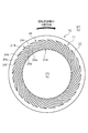
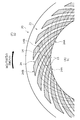
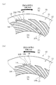
- FIG. 1 It is a vertical cross-sectional view which shows an example of the mechanical seal in Example 1 of this invention. It is the figure which looked at the sliding surface of the rotary sealing ring from the axial direction. It is the figure which looked at the sliding surface of the static sealing ring from the axial direction. It is the schematic explaining the state in which the sliding surface of a static sealing ring and the sliding surface of a rotary sealing ring are arranged facing each other.
- the first positive pressure generating groove of the statically sealed ring is indicated by a two-dot broken line. It is sectional drawing which shows typically the 1st positive pressure generation groove and the 2nd positive pressure generation groove.
- (A) is an explanatory view of the movement of the fluid in the second positive pressure generating groove seen from the axial direction
- (b) is an explanatory view of the movement of the fluid in the first positive pressure generating groove seen from the axial direction.
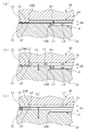
- (A) to (c) are cross-sectional views schematically showing states of a pair of sliding parts for each relative rotation speed. It is explanatory drawing which shows the position change of the intersection of the 1st positive pressure generation groove and the 2nd positive pressure generation groove. The intersection of one first positive pressure generating groove and one second positive pressure generating groove is taken up and illustrated. It is explanatory drawing which shows the modification 1 of the 1st positive pressure generation groove of Example 1.
- the pair of sliding parts according to the first embodiment will be described with reference to FIGS. 1 to 7.
- a form in which the pair of sliding parts is a mechanical seal will be described as an example.
- the sealed fluid exists in the outer space of the mechanical seal, and the atmosphere exists in the inner space.
- the outer diameter side of the sliding parts constituting the mechanical seal is the sealed fluid side (high pressure side), and the inner diameter side is the inner diameter side. This will be described as the leak side (low pressure side).
- dots may be added to the grooves and the like formed on the sliding surface in the drawings.
- the mechanical seal for general industrial machinery shown in FIG. 1 is an inside type that seals the sealed fluid F that tends to leak from the outer diameter side to the inner diameter side of the sliding surface and allows the inner space S1 to communicate with the atmosphere A.
- the sealed fluid F is a high-pressure liquid and the atmosphere A is a gas having a lower pressure than the sealed fluid F is illustrated.
- the mechanical seal includes a rotary seal ring 20 as an annular second sliding component attached to a sleeve 2 fixed to the rotary shaft 1 and rotatably provided together with the rotary shaft 1, and a housing 4 of the device to be attached. It is mainly composed of an annular static sealing ring 10 as a first sliding component provided on the seal cover 5 fixed to the seal cover 5 in a non-rotating state and in a state of being movable in the axial direction, and is statically sealed by a bellows 7. By urging 10 in the axial direction, the sliding surface 11 of the static sealing ring 10 and the sliding surface 21 of the rotary sealing ring 20 slide closely with each other.
- the static sealing ring 10 and the rotary sealing ring 20 are typically formed of SiC (hard material) or a combination of SiC (hard material) and carbon (soft material), but the sliding material is not limited to this. It can be applied as long as it is used as a sliding material for mechanical seals.
- the SiC includes a sintered body using boron, aluminum, carbon and the like as a sintering aid, and materials composed of two or more types of phases having different components and compositions, for example, SiC and SiC in which graphite particles are dispersed.
- carbon in which carbon and graphite are mixed.
- metal materials, resin materials, surface modification materials (coating materials), composite materials and the like can also be applied.
- a plurality of second positive pressure generating grooves 24, for example, 24 in the first embodiment, are evenly arranged in the circumferential direction on the inner diameter side.
- the portion of the sliding surface 21 other than the second positive pressure generating groove 24 is a land 22 forming a flat surface.
- the end on the inner diameter side that is, the relative rotation starting end 24A communicates with the inner space S1
- the second positive pressure generating groove 24 is inclined from the starting end 24A toward the outer diameter side toward the upstream side in the rotation direction of the rotary sealing ring 20. It extends in an arc shape, and the end portion on the outer diameter side, that is, the relative rotation end 24B is closed so as not to communicate with the outer space S2.
- the second positive pressure generating groove 24 has an arc shape having a protrusion toward the outer diameter side.
- the second positive pressure generating groove 24 extends from the start end 24A to the end 24B to the bottom surface 24a which is flat and parallel to the flat surface of the land 22, and from the edge of the end 24B of the bottom surface 24a to the flat surface of the land 22. It is composed of a wall portion 24b extending vertically toward the wall and side wall portions 24c and 24d extending vertically from the side edge of the bottom surface 24a toward the flat surface of the land 22.
- the angle formed by the wall portion 24b and the side wall portion 24c is an obtuse angle
- the angle formed by the wall portion 24b and the side wall portion 24d is an acute angle
- the acute angle portion 24f on the side wall portion 24d side of the wall portion 24b is the wall. It is located on the upstream side in the rotation direction of the rotary sealing ring 20 with respect to the obtuse angle portion 24e on the side wall portion 24c side of the portion 24b.
- a plurality of second positive pressure generating grooves 24 are arranged so as to overlap in the radial direction when viewed from the axial direction, for example, in the first embodiment.
- a plurality of second positive pressure generating grooves 24 are arranged on the radius line, for example, in the first embodiment, three second positive pressure generating grooves 24 are arranged.
- first positive pressure generating grooves 14 are evenly arranged in the circumferential direction.
- the portion of the sliding surface 11 other than the first positive pressure generating groove 14 is a land 12 forming a flat surface.
- the first positive pressure generating groove 14 is a circle in which the end on the inner diameter side, that is, the relative rotation start end 14A communicates with the inner space S1, and is inclined downstream from the start end 14A toward the outer diameter side in the rotation direction of the rotary sealing ring 20. It extends in an arc shape, and the end portion on the outer diameter side, that is, the relative rotation end 14B is closed so as not to communicate with the outer space S2.
- the first positive pressure generating groove 14 has an arc shape having a protrusion toward the outer diameter side.
- the first positive pressure generating groove 14 is flat from the start end 14A to the end 14B and parallel to the flat surface of the land 12, and from the edge of the end 14B of the bottom surface 14a to the flat surface of the land 12. It is composed of a wall portion 14b extending vertically toward the wall and side wall portions 14c and 14d extending vertically from the side edge of the bottom surface 14a toward the flat surface of the land 12.
- the angle formed by the wall portion 14b and the side wall portion 14c is an obtuse angle
- the angle formed by the wall portion 14b and the side wall portion 14d is an acute angle
- the acute angle portion 14f on the side wall portion 14d side of the wall portion 14b is the wall. It is located downstream of the obtuse angle portion 14e on the side wall portion 14c side of the portion 14b in the rotational direction of the rotary sealing ring 20.
- a plurality of first positive pressure generating grooves 14 are arranged so as to overlap each other in the radial direction when viewed from the axial direction, for example, in the first embodiment.
- a plurality of first positive pressure generating grooves 14 are arranged on the radius line, for example, in the first embodiment.
- the first positive pressure generating groove 14 and the second positive pressure are generated.
- the generation groove 24 is arranged so as to intersect with each other when viewed from the axial direction.
- the sliding surface 21 of the rotary sealing ring 20 viewed from the axial direction is shown
- the second positive pressure generating groove 24 is shown by a solid line
- the opposing first positive pressure generating groove 14 is shown by a two-dot broken line.
- a plurality of the first positive pressure generating grooves 14 and five second positive pressure generating grooves 24 in this embodiment are arranged so as to intersect each other and one second positive pressure is generated.
- a plurality of first positive pressure generating grooves 14 in this embodiment intersect and are arranged to face each other in the generating grooves 24. That is, a plurality of intersections 15 of the first positive pressure generating groove 14 and the second positive pressure generating groove 24 are formed.
- the length from the start end 14A to the end 14B of the first positive pressure generating groove 14, that is, the extending distance L10 of the first positive pressure generating groove 14 is the second positive pressure.
- FIG. 5 is a schematic view in which the cross sections of the first positive pressure generating groove 14 of the first row and the second positive pressure generating groove 24 of the first row cut in the longitudinal direction are arranged at the same position in the axial direction. It is a cross-sectional view.
- the extending distance L10 of the first positive pressure generating groove 14 is about 2/3 of the extending distance L20 of the second positive pressure generating groove 24.
- the end 24B of the second positive pressure generation groove 24 is arranged on the outer diameter side of the end 14B of the first positive pressure generation groove 14.
- the width dimensions of the first positive pressure generating groove 14 and the second positive pressure generating groove 24 are almost the same. That is, since the extending distance L10 of the first positive pressure generating groove 14 is shorter than the extending distance L20 of the second positive pressure generating groove 24, the area of the first positive pressure generating groove 14 seen from the axial direction is the second. It is smaller than the area of the positive pressure generating groove 24.
- the first positive pressure generating groove 14 has a constant depth D1 from the start end 14A to the end end 14B.
- the second positive pressure generation groove 24 has a constant depth D2 from the start end 24A to the end end 24B.
- the volumes of the first positive pressure generating groove 14 and the second positive pressure generating groove 24 are obtained by multiplying the areas of the first positive pressure generating groove 14 and the second positive pressure generating groove 24 when viewed from the axial direction by the depths D1 and D2. It is required by that. As described above, the area of the first positive pressure generating groove 14 viewed from the axial direction is smaller than the area of the second positive pressure generating groove 24, and the depths D1 and the second positive pressure of the first positive pressure generating groove 14 Since the depth D2 of the generation groove 24 has the same dimensions, the capacity of the first positive pressure generation groove 14 is smaller than the volume of the second positive pressure generation groove 24.
- the inclination of the first positive pressure generating groove 14 with respect to the inner peripheral surface of the static sealing ring 10 in the circumferential direction is about the sliding surface 21.
- the degree of inclination of the rotary sealing ring 20 with respect to the inner peripheral surface of the rotary sealing ring 20 in the circumferential direction is the same as that of the second positive pressure generating groove 24.
- Atmosphere A that has moved toward the end 24B is increased in pressure at and near the acute-angled portion 24f of the wall portion 24b of the second positive pressure generation groove 24, and is between the sliding surfaces 11 and 21 as shown by the arrow L2. leak. That is, a positive pressure is generated at the acute angle portion 24f and its vicinity.
- the atmosphere A in the second positive pressure generating groove 24 indicated by the arrow L2 acts to push the sealed fluid F near the end 24B of the second positive pressure generating groove 24 back to the outer space S2 side, so that the sealed fluid F Does not leak into the inner space S1.
- the atmosphere A in the first positive pressure generation groove 14 receives a shearing force from the sliding surface 21 and rotates. While following the rotation direction of the sealing ring 20, the atmosphere A in the inner space S1 is drawn into the first positive pressure generating groove 14. That is, in the first positive pressure generation groove 14, the atmosphere A moves from the start end 14A toward the end end 14B as shown by the arrow L3.
- Atmosphere A that has moved toward the end 14B is increased in pressure at and near the acute-angled portion 14f of the wall portion 14b of the first positive pressure generating groove 14, and is between the sliding surfaces 11 and 21 as shown by the arrow L4. leak. That is, a positive pressure is generated at the acute angle portion 14f and its vicinity.
- the atmosphere A in the first positive pressure generating groove 14 indicated by the arrow L4 acts to push the sealed fluid F near the end 14B of the first positive pressure generating groove 14 back to the outer space S2 side, so that the sealed fluid F Does not leak into the inner space S1.
- the first positive pressure generating groove 24 has a capacity smaller than that of the second positive pressure generating groove 24, as shown in FIG. 7A. Positive pressure is generated at the end 14B of the positive pressure generation groove 14.
- the first force F1 due to the positive pressure generated at the end 14B of the first positive pressure generating groove 14 causes the sliding surfaces 11 and 21 to be slightly separated ⁇ a.
- the sealed fluid F flows into the outer diameter side between the sliding surfaces 11 and 21 from the outer space S2.
- the lubricity is improved even during low-speed rotation, and wear between the sliding surfaces 11 and 21 can be suppressed. Since the floating distance between the sliding surfaces 11 and 21 is small, the sealed fluid F does not leak into the inner space S1.
- the atmosphere A since the capacity of the second positive pressure generating groove 24 is larger than the capacity of the first positive pressure generating groove 14, the atmosphere A generates the second positive pressure when the relative rotation speed between the rotary sealing ring 20 and the static sealing ring 10 is low.
- the groove 24 is not sufficiently dense and a high positive pressure is not generated, and the second force F2 (not shown in FIG. 7A) due to the positive pressure generated by the second positive pressure generating groove 24 is the second. It is relatively smaller than 1 force F1. Therefore, when the rotary sealing ring 20 is rotated at a low speed, the first force F1 is the main force to separate the sliding surfaces 11 and 21 from each other.
- a second force F2 due to the positive pressure generated at the end 24B of the second positive pressure generation groove 24 is applied, and the sliding surfaces 11 and 21 are further separated by ⁇ b ( ⁇ b> ⁇ a) as compared with FIG. 7A.
- the atmosphere A in the second positive pressure generating groove 24 flows into the sliding surfaces 11 and 21 mainly as shown by the arrow L2.
- the first force F1' is smaller than that of FIG. 7A because the sliding surfaces 11 and 21 are further separated from each other by ⁇ b ( ⁇ b> ⁇ a) as compared with FIG. 7A.
- the second force F2' is mainly used to separate the sliding surfaces 11 and 21 from each other.
- a plurality of intersections 15 of the first positive pressure generating groove 14 and the second positive pressure generating groove 24 are formed, and the atmosphere A is formed in the first positive pressure generating groove 14 from the starting end 14A side.
- the atmosphere A is also introduced from the second positive pressure generation groove 24 through the intersection 15, so that the first force F1 (see FIG. 7) that separates the sliding surfaces 11 and 21 is set early. Can be generated in.
- FIG. 8A shows a state in which the starting end 14A of the first positive pressure generating groove 14 and the starting end 24A of the second positive pressure generating groove 24 intersect when viewed from the axial direction. That is, the intersection 15 with the second positive pressure generating groove 24 is located at the starting end 14A of the first positive pressure generating groove 14.
- the fluid in the second positive pressure generation groove 24 is collected in the intersection 15 by the side wall portion 14d of the first positive pressure generation groove 14, and the intersection 15 is the first positive pressure generation groove 14 and the second positive.
- the pressure is higher than that of the portion of the pressure generating groove 24 other than the intersection 15.
- intersection 15 moves as shown in FIG. 8C and is located at the end 14B of the first positive pressure generating groove 14.
- a mass of fluid collected in the intersection 15 receives a shearing force at the side wall portion 24d of the second positive pressure generating groove 24 and the acute angle portion 14f of the first positive pressure generating groove 14, and a large positive pressure is generated. It is designed to do.
- the fluid mass in the intersection 15 is moved from the start end 14A side of the first positive pressure generation groove 14 to the end 14B, and a large positive pressure is generated at the end 14B of the first positive pressure generation groove 14. Therefore, the first force F1 (see FIG. 7) that separates the sliding surfaces 11 and 21 can be generated at an early stage.
- the sliding surface 11 of the static sealing ring 10 and the sliding surface 21 of the rotary sealing ring 20 slide in a state where the first positive pressure generating groove 14 and the second positive pressure generating groove 24 intersect. Since the intersection 15 of the first positive pressure generating groove 14 and the second positive pressure generating groove 24 communicates with each other, the starting end 14A of the first positive pressure generating groove 14 is reached when the relative rotation speed is low. In addition, the fluid can be taken in from the opposite second positive pressure generation groove 24, and the first force F1 can be immediately generated.
- the first positive pressure generating groove 14 is used when the relative rotation speed between the static sealing ring 10 and the rotary sealing ring 20 is low.
- the sliding surfaces 11 and 21 are separated from each other mainly by the first force F1 due to the positive pressure generated by the atmosphere A inside.
- the gap formed between the sliding surfaces 11 and 21 becomes large, so that positive pressure is less likely to be generated in the first positive pressure generating groove 14.
- the second force F2 due to the positive pressure generated in the second positive pressure generation groove 24 is the main component, and the sliding surfaces 11 and 21 can be stably separated from each other. Therefore, it is possible to suppress wear between the sliding surfaces 11 and 21 from the relative rotation speed of the static sealing ring 10 and the rotating sealing ring 20 to the high speed.
- a plurality of second positive pressure generating grooves 24 intersect with one first positive pressure generating groove 14, and when the static sealing ring 10 and the rotary sealing ring 20 are relatively rotated, a plurality of first positive pressures are generated. Since the atmosphere A can be taken into the generation groove 14 from the second positive pressure generation groove 24, the first force F1 can be generated at an early stage.
- the positive pressure can be continuously generated in the first positive pressure generating groove 14, and the first force F1 can be stably generated. ..
- first positive pressure generating groove 14 and the second positive pressure generating groove 24 extend in the circumferential direction from the inner space S1 side toward the outer diameter side. According to this, many first positive pressure generating grooves 14 and second positive pressure generating grooves 24 can be arranged on the sliding surfaces 11 and 21 of the static sealing ring 10 and the rotary sealing ring 20, so that the degree of freedom in design is high. ..
- the end 14B of the first positive pressure generation groove 14 and the end 24B of the second positive pressure generation groove 24 are displaced in the radial direction, and the positive pressure and the second positive generated at the end 14B of the first positive pressure generation groove 14 Since the positive pressure generated at the end 24B of the pressure generating groove 24 does not interfere with each other, the sliding surfaces 11 and 21 can be stably separated from each other.
- the extending distance L10 of the first positive pressure generating groove 14 is shorter than the extending distance L20 of the second positive pressure generating groove 24. According to this, since the end 14B of the first positive pressure generation groove 14 is closer to the start end 14A communicating with the inner space S1 than the end 24B of the second positive pressure generation groove 24, the first positive pressure generation groove 14 can be reached earlier. Positive pressure can be generated.
- the sizes of the first positive pressure F1 and the second positive pressure F2 can be adjusted, so that the first positive pressure generating groove can be adjusted.
- the depth and width of the 14 and the second positive pressure generating groove 24 can be made the same size, and the design is simple.
- the static sealing ring 10 is provided with the first positive pressure generating groove 14, the positive pressure generated in the first positive pressure generating groove 14 is stable when the rotary sealing ring 20 is rotated at a low speed. Further, since the rotary sealing ring 20 is provided with the second positive pressure generating groove 24, it is easy to introduce the fluid into the second positive pressure generating groove 24, and the sliding surfaces 11 and 21 mainly composed of the second force F2 are connected to each other. The transition to separation can be done at an early stage.
- the extension distance L10 of the first positive pressure generating groove 14 is about two-thirds of the extending distance L20 of the second positive pressure generating groove 24, but FIG.
- the length of the second positive pressure generating groove 140 of the static sealing ring 100 may be about 1/3 of the length of the second positive pressure generating groove 24 (see FIG. 2). That is, the lengths of the first positive pressure generating groove and the second positive pressure generating groove may be freely changed.
- FIG. 10 is a schematic cross section in which the first positive pressure generating groove of Article 1 and the second positive pressure generating groove of Article 1 are cut in the longitudinal direction and arranged at the same position in the axial direction. It is a figure.
- the second positive pressure generation groove 241 of the rotary sealing ring 201 has a constant depth D20 from the start end 241A to the end end 241B.
- the first positive pressure generation groove 141 of the static sealing ring 101 has a constant depth D10 from the start end 141A to the end end 141B.
- the depth D20 of the second positive pressure generating groove 241 is deeper than the depth D10 of the first positive pressure generating groove 141 (D10 ⁇ D20).
- the width dimension of the first positive pressure generating groove 141 and the width dimension of the second positive pressure generating groove 241 are the same.
- the first positive pressure generating groove 141 becomes the first positive pressure generating groove 141 when the relative rotation speed between the static sealing ring 101 and the rotating sealing ring 201 is low.
- the sliding surfaces 111, 211 are separated from each other mainly by the first force (not shown) due to the generated positive pressure.
- the atmosphere A on the bottom surface 141a side of the first positive pressure generating groove 141 is more susceptible to shearing force than the atmosphere A on the bottom surface 241a side of the second positive pressure generating groove 241. Positive pressure can be generated.
- the extension distance L11 of the first positive pressure generation groove 141 and the extension distance L21 of the second positive pressure generation groove 241 have the same dimensions, but the present invention is limited to this. It suffices that the volume of the first positive pressure generating groove is smaller than the volume of the second positive pressure generating groove.
- the static sealing ring has a length dimension different from that of the second positive pressure generating groove. It may have a pressure generating groove. Further, the rotary sealing ring may have a second positive pressure generating groove having a length dimension different from that of the first positive pressure generating groove.
- the first positive pressure generating groove 142 of the static sealing ring 102 is inclined along the circumferential direction with respect to the second positive pressure generating groove 24 of the rotary sealing ring 20.
- end 142B of the first positive pressure generation groove 142 and the end 24B of the second positive pressure generation groove 24 are provided at the same positions in the radial direction so as to overlap each other when viewed from the axial direction.
- the area R1 of the first positive pressure generating groove 142 viewed from the axial direction is smaller than the area R2 of the second positive pressure generating groove 24 (R1 ⁇ R2).
- the depth of the first positive pressure generating groove 142 and the depth of the second positive pressure generating groove 24 in this embodiment are the same.
- the volume of the first positive pressure generating groove 142 is smaller than the volume of the second positive pressure generating groove 24.
- the area R1 of the first positive pressure generating groove 142 and the area R2 of the second positive pressure generating groove 24 may be the same but different in depth.
- the first positive pressure generating groove 142 of the static sealing ring 102 is inclined along the circumferential direction with respect to the second positive pressure generating groove 24 of the rotary sealing ring 20, so that the static sealing ring 102 and the static sealing ring 102 At the start of relative rotation with the rotary sealing ring 20, the atmosphere A is more likely to be introduced into the first positive pressure generating groove 142 than in the second positive pressure generating groove 24, so that the positive pressure is introduced into the first positive pressure generating groove 142 at an early stage. Can be generated.
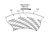
- FIG. 12 the sliding surface of the static sealing ring seen from the axial direction is shown, the first positive pressure generating groove is shown by a solid line, and the facing second positive pressure generating groove is shown by a two-dot broken line.
- the rotary sealing ring 20 has 24 second positive pressure generating grooves 24 arranged in the circumferential direction of the sliding surface 11 (see FIG. 2), and is shown in FIG. As described above, one second positive pressure generating groove 24 has a width W2 in the circumferential direction.
- the static sealing ring 103 is equally arranged with 48 first positive pressure generating grooves 143 formed in the circumferential direction of the sliding surface 131 (only a part thereof is shown here). That is, the number of the first positive pressure generating grooves 143 is twice as large as that of the second positive pressure generating grooves 24.
- the circumferential width W1 of the first positive pressure generating groove 143 is smaller than the circumferential width W2 of the second positive pressure generating groove 24 (W1 ⁇ W2), and the adjacent first positive pressure generating grooves 143 are connected to each other.
- the separation width W3 is smaller than the separation width W4 between the second positive pressure generating grooves 24.
- the extending distance between the first positive pressure generating groove 143 and the second positive pressure generating groove 24 is the same. That is, the area of the first positive pressure generating groove 143 as viewed from the axial direction is smaller than the area of the second positive pressure generating groove 24.
- the depth of the first positive pressure generating groove 143 and the depth of the second positive pressure generating groove 24 in this embodiment are the same. That is, the volume of the first positive pressure generating groove 143 is smaller than the volume of the second positive pressure generating groove 24.
- the first positive pressure generating groove 103 is uniformly first over the circumferential direction of the sliding surface 131 of the static sealing ring 103.
- a force F1 (not shown here) can be generated.
- the volume of the first positive pressure generating groove 143 can be made smaller than the volume of the second positive pressure generating groove 24, the positive pressure can be generated in the first positive pressure generating groove 143 at an early stage.
- the first positive pressure generating groove 143 is formed on the sliding surface 131 of the static sealing ring 103 in a double number of the second positive pressure generating groove 24.
- the sliding surface 151 of the static sealing ring 104 may be provided with the same number of first positive pressure generating grooves 143 as the second positive pressure generating grooves 24, for example, 24 pieces. If the volume of the second positive pressure generating groove is smaller than the volume of the first positive pressure generating groove, the second positive pressure generating groove may be provided in a smaller quantity than the first positive pressure generating groove.
- the mechanical seal for general industrial machines has been described as an example as the sliding component, but other mechanical seals for automobiles, water pumps, etc. may be used.
- the present invention is not limited to the mechanical seal, and may be a sliding component other than the mechanical seal such as a slide bearing.
- the present invention is not limited to this, and the static sealing ring is not limited to the first positive pressure generating groove. 2
- the positive pressure generating groove may be provided, and the first positive pressure generating groove may be provided in the rotary sealing ring.
- the first positive pressure generating groove and the second positive pressure generating groove extend from the leak side toward the sealed fluid side in a circumferential direction, but the present invention is not limited to this.
- the first positive pressure generating groove or the second positive pressure generating groove may be formed only by a component extending in the circumferential direction. That is, one of the first positive pressure generating groove and the second positive pressure generating groove has a component extending in the radial direction and a component extending in the circumferential direction, and at least a part of the first positive pressure generating groove and the second positive pressure generating groove is present. It suffices if they face each other so as to intersect at.
- the embodiment in which the cross-sectional shapes of the first positive pressure generating groove and the second positive pressure generating groove are constant in the longitudinal direction is illustrated, but the capacity of the first positive pressure generating groove is the second positive pressure generating groove.
- a step or an inclined surface may be formed on the bottom surfaces of the first positive pressure generating groove and the second positive pressure generating groove.
- the sealed fluid side has been described as the high pressure side and the leak side as the low pressure side, the sealed fluid side may be the low pressure side and the leak side may be the high pressure side, and the sealed fluid side and the leak side are abbreviated.
- the pressure may be the same.
- the present invention is not limited to this, and sliding is not limited to this. It may be an outside type that seals the sealed fluid F that leaks from the inner diameter side to the outer diameter side of the surface.
- the sealed fluid F has been described as a high-pressure liquid, but the sealed fluid F is not limited to this, and may be a gas or a low-pressure liquid, or may be a mist in which a liquid and a gas are mixed.
- the fluid on the leak side is atmosphere A, which is a low-pressure gas, but the present invention is not limited to this, and it may be a liquid or a high-pressure gas, or a mist-like mixture of a liquid and a gas. It may be.
Landscapes
- Engineering & Computer Science (AREA)
- General Engineering & Computer Science (AREA)
- Mechanical Engineering (AREA)
- Physics & Mathematics (AREA)
- Fluid Mechanics (AREA)
- Mechanical Sealing (AREA)
Abstract
Priority Applications (5)
| Application Number | Priority Date | Filing Date | Title |
|---|---|---|---|
| CN202180029043.0A CN115427713A (zh) | 2020-04-22 | 2021-04-02 | 一对滑动部件 |
| KR1020227037943A KR20220160673A (ko) | 2020-04-22 | 2021-04-02 | 한 쌍의 슬라이딩 부품 |
| US17/920,009 US20230167905A1 (en) | 2020-04-22 | 2021-04-02 | Pair of sliding components |
| EP21793420.7A EP4141275A4 (fr) | 2020-04-22 | 2021-04-02 | Paire de composants coulissants |
| JP2022516931A JPWO2021215224A1 (fr) | 2020-04-22 | 2021-04-02 |
Applications Claiming Priority (2)
| Application Number | Priority Date | Filing Date | Title |
|---|---|---|---|
| JP2020075820 | 2020-04-22 | ||
| JP2020-075820 | 2020-04-22 |
Publications (1)
| Publication Number | Publication Date |
|---|---|
| WO2021215224A1 true WO2021215224A1 (fr) | 2021-10-28 |
Family
ID=78269138
Family Applications (1)
| Application Number | Title | Priority Date | Filing Date |
|---|---|---|---|
| PCT/JP2021/014347 WO2021215224A1 (fr) | 2020-04-22 | 2021-04-02 | Paire de composants coulissants |
Country Status (6)
| Country | Link |
|---|---|
| US (1) | US20230167905A1 (fr) |
| EP (1) | EP4141275A4 (fr) |
| JP (1) | JPWO2021215224A1 (fr) |
| KR (1) | KR20220160673A (fr) |
| CN (1) | CN115427713A (fr) |
| WO (1) | WO2021215224A1 (fr) |
Families Citing this family (1)
| Publication number | Priority date | Publication date | Assignee | Title |
|---|---|---|---|---|
| KR102646386B1 (ko) * | 2019-02-15 | 2024-03-12 | 이구루코교 가부시기가이샤 | 슬라이딩 부품 |
Citations (5)
| Publication number | Priority date | Publication date | Assignee | Title |
|---|---|---|---|---|
| JPS60170286A (ja) | 1984-02-14 | 1985-09-03 | 富士通株式会社 | ガラスセラミツク基板の製造方法 |
| JPS6231775A (ja) | 1985-07-31 | 1987-02-10 | Ebara Res Co Ltd | 軸封装置 |
| WO2013035502A1 (fr) * | 2011-09-10 | 2013-03-14 | イーグル工業株式会社 | Elément glissant |
| WO2016167262A1 (fr) * | 2015-04-15 | 2016-10-20 | イーグル工業株式会社 | Pièces coulissantes |
| JP2020173020A (ja) * | 2019-04-09 | 2020-10-22 | イーグル工業株式会社 | 摺動部品 |
Family Cites Families (4)
| Publication number | Priority date | Publication date | Assignee | Title |
|---|---|---|---|---|
| JPS59231268A (ja) * | 1983-06-14 | 1984-12-25 | Arai Pump Mfg Co Ltd | メカニカルシ−ル |
| JPS59231269A (ja) * | 1983-06-14 | 1984-12-25 | Arai Pump Mfg Co Ltd | メカニカルシ−ル |
| DE4409021A1 (de) * | 1994-03-16 | 1995-09-21 | Burgmann Dichtungswerk Feodor | Berührungsfrei laufende, gasgeschmierte Gleitringdichtung |
| US6152452A (en) * | 1997-10-17 | 2000-11-28 | Wang; Yuming | Face seal with spiral grooves |
-
2021
- 2021-04-02 EP EP21793420.7A patent/EP4141275A4/fr active Pending
- 2021-04-02 US US17/920,009 patent/US20230167905A1/en active Pending
- 2021-04-02 JP JP2022516931A patent/JPWO2021215224A1/ja active Pending
- 2021-04-02 CN CN202180029043.0A patent/CN115427713A/zh active Pending
- 2021-04-02 WO PCT/JP2021/014347 patent/WO2021215224A1/fr unknown
- 2021-04-02 KR KR1020227037943A patent/KR20220160673A/ko unknown
Patent Citations (5)
| Publication number | Priority date | Publication date | Assignee | Title |
|---|---|---|---|---|
| JPS60170286A (ja) | 1984-02-14 | 1985-09-03 | 富士通株式会社 | ガラスセラミツク基板の製造方法 |
| JPS6231775A (ja) | 1985-07-31 | 1987-02-10 | Ebara Res Co Ltd | 軸封装置 |
| WO2013035502A1 (fr) * | 2011-09-10 | 2013-03-14 | イーグル工業株式会社 | Elément glissant |
| WO2016167262A1 (fr) * | 2015-04-15 | 2016-10-20 | イーグル工業株式会社 | Pièces coulissantes |
| JP2020173020A (ja) * | 2019-04-09 | 2020-10-22 | イーグル工業株式会社 | 摺動部品 |
Non-Patent Citations (1)
| Title |
|---|
| See also references of EP4141275A4 |
Also Published As
| Publication number | Publication date |
|---|---|
| KR20220160673A (ko) | 2022-12-06 |
| CN115427713A (zh) | 2022-12-02 |
| EP4141275A4 (fr) | 2024-05-22 |
| US20230167905A1 (en) | 2023-06-01 |
| JPWO2021215224A1 (fr) | 2021-10-28 |
| EP4141275A1 (fr) | 2023-03-01 |
Similar Documents
| Publication | Publication Date | Title |
|---|---|---|
| WO2020166588A1 (fr) | Éléments coulissants | |
| JP7387239B2 (ja) | 摺動部品 | |
| JP7366945B2 (ja) | 摺動部品 | |
| JP7374573B2 (ja) | 摺動部品 | |
| CN113330224A (zh) | 滑动部件 | |
| WO2020162352A1 (fr) | Élément coulissant | |
| WO2021215224A1 (fr) | Paire de composants coulissants | |
| WO2021182168A1 (fr) | Composant de coulissement | |
| WO2020162349A1 (fr) | Élément coulissant | |
| WO2023026755A1 (fr) | Paire de composants coulissants | |
| WO2023027003A1 (fr) | Composant coulissant | |
| WO2021193743A1 (fr) | Élément coulissant | |
| WO2023027102A1 (fr) | Composant coulissant | |
| WO2023223914A1 (fr) | Composant coulissant | |
| WO2024053637A1 (fr) | Composant de glissement | |
| EP4130523A1 (fr) | Composant coulissant | |
| WO2023053964A1 (fr) | Composant coulissant | |
| WO2024004657A1 (fr) | Composant coulissant |
Legal Events
| Date | Code | Title | Description |
|---|---|---|---|
| 121 | Ep: the epo has been informed by wipo that ep was designated in this application |
Ref document number: 21793420 Country of ref document: EP Kind code of ref document: A1 |
|
| ENP | Entry into the national phase |
Ref document number: 2022516931 Country of ref document: JP Kind code of ref document: A |
|
| ENP | Entry into the national phase |
Ref document number: 20227037943 Country of ref document: KR Kind code of ref document: A |
|
| NENP | Non-entry into the national phase |
Ref country code: DE |
|
| ENP | Entry into the national phase |
Ref document number: 2021793420 Country of ref document: EP Effective date: 20221122 |