WO2021215086A1 - Battery - Google Patents
Battery Download PDFInfo
- Publication number
- WO2021215086A1 WO2021215086A1 PCT/JP2021/005349 JP2021005349W WO2021215086A1 WO 2021215086 A1 WO2021215086 A1 WO 2021215086A1 JP 2021005349 W JP2021005349 W JP 2021005349W WO 2021215086 A1 WO2021215086 A1 WO 2021215086A1
- Authority
- WO
- WIPO (PCT)
- Prior art keywords
- active material
- material layer
- negative electrode
- solid electrolyte
- layer
- Prior art date
Links
Images


Classifications
-
- H—ELECTRICITY
- H01—ELECTRIC ELEMENTS
- H01M—PROCESSES OR MEANS, e.g. BATTERIES, FOR THE DIRECT CONVERSION OF CHEMICAL ENERGY INTO ELECTRICAL ENERGY
- H01M10/00—Secondary cells; Manufacture thereof
- H01M10/05—Accumulators with non-aqueous electrolyte
- H01M10/058—Construction or manufacture
- H01M10/0585—Construction or manufacture of accumulators having only flat construction elements, i.e. flat positive electrodes, flat negative electrodes and flat separators
-
- H—ELECTRICITY
- H01—ELECTRIC ELEMENTS
- H01M—PROCESSES OR MEANS, e.g. BATTERIES, FOR THE DIRECT CONVERSION OF CHEMICAL ENERGY INTO ELECTRICAL ENERGY
- H01M4/00—Electrodes
- H01M4/02—Electrodes composed of, or comprising, active material
- H01M4/36—Selection of substances as active materials, active masses, active liquids
- H01M4/362—Composites
- H01M4/366—Composites as layered products
-
- H—ELECTRICITY
- H01—ELECTRIC ELEMENTS
- H01M—PROCESSES OR MEANS, e.g. BATTERIES, FOR THE DIRECT CONVERSION OF CHEMICAL ENERGY INTO ELECTRICAL ENERGY
- H01M10/00—Secondary cells; Manufacture thereof
- H01M10/05—Accumulators with non-aqueous electrolyte
- H01M10/052—Li-accumulators
-
- H—ELECTRICITY
- H01—ELECTRIC ELEMENTS
- H01M—PROCESSES OR MEANS, e.g. BATTERIES, FOR THE DIRECT CONVERSION OF CHEMICAL ENERGY INTO ELECTRICAL ENERGY
- H01M10/00—Secondary cells; Manufacture thereof
- H01M10/05—Accumulators with non-aqueous electrolyte
- H01M10/052—Li-accumulators
- H01M10/0525—Rocking-chair batteries, i.e. batteries with lithium insertion or intercalation in both electrodes; Lithium-ion batteries
-
- H—ELECTRICITY
- H01—ELECTRIC ELEMENTS
- H01M—PROCESSES OR MEANS, e.g. BATTERIES, FOR THE DIRECT CONVERSION OF CHEMICAL ENERGY INTO ELECTRICAL ENERGY
- H01M10/00—Secondary cells; Manufacture thereof
- H01M10/05—Accumulators with non-aqueous electrolyte
- H01M10/056—Accumulators with non-aqueous electrolyte characterised by the materials used as electrolytes, e.g. mixed inorganic/organic electrolytes
- H01M10/0561—Accumulators with non-aqueous electrolyte characterised by the materials used as electrolytes, e.g. mixed inorganic/organic electrolytes the electrolyte being constituted of inorganic materials only
- H01M10/0562—Solid materials
-
- H—ELECTRICITY
- H01—ELECTRIC ELEMENTS
- H01M—PROCESSES OR MEANS, e.g. BATTERIES, FOR THE DIRECT CONVERSION OF CHEMICAL ENERGY INTO ELECTRICAL ENERGY
- H01M4/00—Electrodes
- H01M4/02—Electrodes composed of, or comprising, active material
- H01M4/13—Electrodes for accumulators with non-aqueous electrolyte, e.g. for lithium-accumulators; Processes of manufacture thereof
- H01M4/133—Electrodes based on carbonaceous material, e.g. graphite-intercalation compounds or CFx
-
- H—ELECTRICITY
- H01—ELECTRIC ELEMENTS
- H01M—PROCESSES OR MEANS, e.g. BATTERIES, FOR THE DIRECT CONVERSION OF CHEMICAL ENERGY INTO ELECTRICAL ENERGY
- H01M4/00—Electrodes
- H01M4/02—Electrodes composed of, or comprising, active material
- H01M4/13—Electrodes for accumulators with non-aqueous electrolyte, e.g. for lithium-accumulators; Processes of manufacture thereof
- H01M4/134—Electrodes based on metals, Si or alloys
-
- H—ELECTRICITY
- H01—ELECTRIC ELEMENTS
- H01M—PROCESSES OR MEANS, e.g. BATTERIES, FOR THE DIRECT CONVERSION OF CHEMICAL ENERGY INTO ELECTRICAL ENERGY
- H01M4/00—Electrodes
- H01M4/02—Electrodes composed of, or comprising, active material
- H01M4/36—Selection of substances as active materials, active masses, active liquids
- H01M4/362—Composites
- H01M4/364—Composites as mixtures
-
- H—ELECTRICITY
- H01—ELECTRIC ELEMENTS
- H01M—PROCESSES OR MEANS, e.g. BATTERIES, FOR THE DIRECT CONVERSION OF CHEMICAL ENERGY INTO ELECTRICAL ENERGY
- H01M4/00—Electrodes
- H01M4/02—Electrodes composed of, or comprising, active material
- H01M4/36—Selection of substances as active materials, active masses, active liquids
- H01M4/38—Selection of substances as active materials, active masses, active liquids of elements or alloys
- H01M4/381—Alkaline or alkaline earth metals elements
- H01M4/382—Lithium
-
- H—ELECTRICITY
- H01—ELECTRIC ELEMENTS
- H01M—PROCESSES OR MEANS, e.g. BATTERIES, FOR THE DIRECT CONVERSION OF CHEMICAL ENERGY INTO ELECTRICAL ENERGY
- H01M4/00—Electrodes
- H01M4/02—Electrodes composed of, or comprising, active material
- H01M4/36—Selection of substances as active materials, active masses, active liquids
- H01M4/38—Selection of substances as active materials, active masses, active liquids of elements or alloys
- H01M4/386—Silicon or alloys based on silicon
-
- H—ELECTRICITY
- H01—ELECTRIC ELEMENTS
- H01M—PROCESSES OR MEANS, e.g. BATTERIES, FOR THE DIRECT CONVERSION OF CHEMICAL ENERGY INTO ELECTRICAL ENERGY
- H01M4/00—Electrodes
- H01M4/02—Electrodes composed of, or comprising, active material
- H01M4/36—Selection of substances as active materials, active masses, active liquids
- H01M4/38—Selection of substances as active materials, active masses, active liquids of elements or alloys
- H01M4/387—Tin or alloys based on tin
-
- H—ELECTRICITY
- H01—ELECTRIC ELEMENTS
- H01M—PROCESSES OR MEANS, e.g. BATTERIES, FOR THE DIRECT CONVERSION OF CHEMICAL ENERGY INTO ELECTRICAL ENERGY
- H01M4/00—Electrodes
- H01M4/02—Electrodes composed of, or comprising, active material
- H01M4/36—Selection of substances as active materials, active masses, active liquids
- H01M4/58—Selection of substances as active materials, active masses, active liquids of inorganic compounds other than oxides or hydroxides, e.g. sulfides, selenides, tellurides, halogenides or LiCoFy; of polyanionic structures, e.g. phosphates, silicates or borates
- H01M4/583—Carbonaceous material, e.g. graphite-intercalation compounds or CFx
- H01M4/587—Carbonaceous material, e.g. graphite-intercalation compounds or CFx for inserting or intercalating light metals
-
- H—ELECTRICITY
- H01—ELECTRIC ELEMENTS
- H01M—PROCESSES OR MEANS, e.g. BATTERIES, FOR THE DIRECT CONVERSION OF CHEMICAL ENERGY INTO ELECTRICAL ENERGY
- H01M4/00—Electrodes
- H01M4/02—Electrodes composed of, or comprising, active material
- H01M4/62—Selection of inactive substances as ingredients for active masses, e.g. binders, fillers
-
- H—ELECTRICITY
- H01—ELECTRIC ELEMENTS
- H01M—PROCESSES OR MEANS, e.g. BATTERIES, FOR THE DIRECT CONVERSION OF CHEMICAL ENERGY INTO ELECTRICAL ENERGY
- H01M4/00—Electrodes
- H01M4/02—Electrodes composed of, or comprising, active material
- H01M2004/021—Physical characteristics, e.g. porosity, surface area
-
- H—ELECTRICITY
- H01—ELECTRIC ELEMENTS
- H01M—PROCESSES OR MEANS, e.g. BATTERIES, FOR THE DIRECT CONVERSION OF CHEMICAL ENERGY INTO ELECTRICAL ENERGY
- H01M4/00—Electrodes
- H01M4/02—Electrodes composed of, or comprising, active material
- H01M2004/026—Electrodes composed of, or comprising, active material characterised by the polarity
- H01M2004/027—Negative electrodes
-
- H—ELECTRICITY
- H01—ELECTRIC ELEMENTS
- H01M—PROCESSES OR MEANS, e.g. BATTERIES, FOR THE DIRECT CONVERSION OF CHEMICAL ENERGY INTO ELECTRICAL ENERGY
- H01M2300/00—Electrolytes
- H01M2300/0017—Non-aqueous electrolytes
- H01M2300/0065—Solid electrolytes
- H01M2300/0068—Solid electrolytes inorganic
-
- Y—GENERAL TAGGING OF NEW TECHNOLOGICAL DEVELOPMENTS; GENERAL TAGGING OF CROSS-SECTIONAL TECHNOLOGIES SPANNING OVER SEVERAL SECTIONS OF THE IPC; TECHNICAL SUBJECTS COVERED BY FORMER USPC CROSS-REFERENCE ART COLLECTIONS [XRACs] AND DIGESTS
- Y02—TECHNOLOGIES OR APPLICATIONS FOR MITIGATION OR ADAPTATION AGAINST CLIMATE CHANGE
- Y02E—REDUCTION OF GREENHOUSE GAS [GHG] EMISSIONS, RELATED TO ENERGY GENERATION, TRANSMISSION OR DISTRIBUTION
- Y02E60/00—Enabling technologies; Technologies with a potential or indirect contribution to GHG emissions mitigation
- Y02E60/10—Energy storage using batteries
-
- Y—GENERAL TAGGING OF NEW TECHNOLOGICAL DEVELOPMENTS; GENERAL TAGGING OF CROSS-SECTIONAL TECHNOLOGIES SPANNING OVER SEVERAL SECTIONS OF THE IPC; TECHNICAL SUBJECTS COVERED BY FORMER USPC CROSS-REFERENCE ART COLLECTIONS [XRACs] AND DIGESTS
- Y02—TECHNOLOGIES OR APPLICATIONS FOR MITIGATION OR ADAPTATION AGAINST CLIMATE CHANGE
- Y02P—CLIMATE CHANGE MITIGATION TECHNOLOGIES IN THE PRODUCTION OR PROCESSING OF GOODS
- Y02P70/00—Climate change mitigation technologies in the production process for final industrial or consumer products
- Y02P70/50—Manufacturing or production processes characterised by the final manufactured product
Definitions
- This disclosure relates to batteries.
- Carbon material is mainly used as the negative electrode active material for the negative electrode of the battery.
- an alloy-based material such as silicon as a negative electrode active material.
- Patent Document 1 describes an all-solid-state battery in which a mixed material of a solid electrolyte containing Li, P and S, a carbon material as a negative electrode active material, and an alloy-based material as a negative electrode active material is used for the negative electrode active material layer. It is disclosed.
- the negative electrode has a negative electrode current collector and a negative electrode active material layer located between the negative electrode current collector and the solid electrolyte layer.
- the negative electrode active material layer includes a first active material layer and a second active material layer located between the first active material layer and the solid electrolyte layer.
- the first active material layer contains a material that alloys with Li as the first active material.
- the second active material layer contains a second active material and a solid electrolyte, and does not contain a material that alloys with Li. Provide batteries.
- both energy density and safety can be achieved at the same time.
- FIG. 1 is a cross-sectional view showing a schematic configuration of a battery according to an embodiment.
- FIG. 2 is a cross-sectional view showing a detailed configuration of the negative electrode.
- FIG. 3 is a cross-sectional view showing the configuration of the negative electrode in the first modification.
- FIG. 4 is a cross-sectional view showing the configuration of the negative electrode in the modified example 2.
- FIG. 5 is a cross-sectional view showing the configuration of the negative electrode in the modified example 3.
- FIG. 6 is a cross-sectional view showing the configuration of the negative electrode in Comparative Example 1.
- FIG. 7 is a cross-sectional view showing the configuration of the negative electrode in Comparative Example 2.
- the alloy-based active material When the alloy-based active material is contained in the negative electrode, the alloy-based active material expands and contracts due to the insertion reaction and the desorption reaction of lithium ions, and the volume of the negative electrode changes significantly. When the particles of the alloy-based active material are large, the particles of the alloy-based active material may penetrate the solid electrolyte layer, which is an insulating layer, as the particles expand. In this case, the function of the battery is lost.
- Solid-state batteries are subject to stricter restrictions on the expansion of the negative electrode active material than batteries using liquid electrolytes.
- One way to solve the above problem is to increase the thickness of the solid electrolyte layer, which is the insulating layer.
- the solid electrolyte layer does not contribute to the energy density of the battery, increasing the thickness of the solid electrolyte layer lowers the energy density of the battery.
- the battery according to the first aspect of the present disclosure is With the positive electrode With the negative electrode A solid electrolyte layer located between the positive electrode and the negative electrode, With The negative electrode has a negative electrode current collector and a negative electrode active material layer located between the negative electrode current collector and the solid electrolyte layer.
- the negative electrode active material layer includes a first active material layer and a second active material layer located between the first active material layer and the solid electrolyte layer.
- the first active material layer contains a material that alloys with Li as the first active material.
- the second active material layer contains a second active material and a solid electrolyte, and does not contain a material that alloys with Li.
- the second active material layer functions as a buffer layer between the first active material layer and the electrolyte layer.
- the first active material layer contains a material that alloys with Li, the energy density of the battery is increased. Therefore, according to the present embodiment, both energy density and safety can be achieved at the same time.
- the second active material may contain a carbon material. Since the expansion coefficient of the carbon material during charging is relatively small, the safety of the battery can be improved by using the carbon material as the second active material.
- the carbon material may contain graphite.
- Graphite is suitable as a second active material because it has a smaller expansion coefficient during the insertion reaction of lithium ions than an alloy-based active material.
- the first active material is at least one selected from the group consisting of silicon, tin, and titanium. It may be included. If these materials are used as the first active material, the energy density of the battery can be increased.
- the first active material layer may be thinner than the second active material layer.
- the first active material layer does not have to contain the second active material. According to such a configuration, a sufficient discharge capacity of the first active material layer can be secured.
- the first active material layer does not have to contain the solid electrolyte. According to such a configuration, a sufficient discharge capacity of the first active material layer can be secured.
- the solid electrolyte may have lithium ion conductivity. According to such a configuration, the lithium ion conductivity of the negative electrode active material layer can be enhanced.
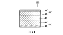
- FIG. 1 is a cross-sectional view showing a schematic configuration of the battery 100 according to the embodiment.
- the battery 100 includes a positive electrode 220, a negative electrode 210, and an electrolyte layer 13.
- the positive electrode 220 has a positive electrode active material layer 17 and a positive electrode current collector 18.
- the positive electrode active material layer 17 is arranged between the electrolyte layer 13 and the positive electrode current collector 18.
- the positive electrode active material layer 17 is in electrical contact with the positive electrode current collector 18.
- the positive electrode current collector 18 is a member having a function of collecting electric power from the positive electrode active material layer 17.
- Examples of the material of the positive electrode current collector 18 include aluminum, aluminum alloy, stainless steel, copper, nickel and the like.
- the positive electrode current collector 18 may be made of aluminum or an aluminum alloy. The dimensions, shape, and the like of the positive electrode current collector 18 can be appropriately selected according to the application of the battery 100.
- the positive electrode active material layer 17 contains a positive electrode active material and a solid electrolyte.
- a material having a property of occluding and releasing metal ions such as lithium ions can be used.
- a lithium-containing transition metal oxide, a transition metal fluoride, a polyanion material, a fluorinated polyanion material, a transition metal sulfide, a transition metal oxysulfide, a transition metal oxynitride, or the like can be used.
- the manufacturing cost can be reduced and the average discharge voltage can be increased.
- the positive electrode active material may contain Li and at least one element selected from the group consisting of Mn, Co, Ni and Al.
- Examples of such a material include Li (NiCoAl) O 2 , Li (NiCoMn) O 2 , LiCoO 2, and the like.
- the positive electrode active material has, for example, the shape of particles.
- the shape of the particles of the positive electrode active material is not particularly limited.
- the shape of the particles of the positive electrode active material can be needle-like, spherical, elliptical spherical or scaly.
- the median diameter of the particles of the positive electrode active material may be 0.1 ⁇ m or more and 100 ⁇ m or less.
- the median diameter of the particles of the positive electrode active material is 0.1 ⁇ m or more, the positive electrode active material and the solid electrolyte can form a good dispersed state in the positive electrode 220. As a result, the charge / discharge characteristics of the battery 100 are improved.
- the median diameter of the particles of the positive electrode active material is 100 ⁇ m or less, the lithium diffusion in the particles of the positive electrode active material becomes fast. Therefore, the battery 100 can operate at a high output.
- the solid electrolyte of the positive electrode 220 at least one selected from the group consisting of a sulfide solid electrolyte, an oxide solid electrolyte, a halide solid electrolyte, a polymer solid electrolyte and a complex hydride solid electrolyte may be used.
- the oxide solid electrolyte has excellent high potential stability. By using the oxide solid electrolyte, the charge / discharge efficiency of the battery 100 can be further improved.
- 30 ⁇ v1 ⁇ 95 may be satisfied with respect to the volume ratio “v1: 100 ⁇ v1” of the positive electrode active material and the solid electrolyte.
- the energy density of the battery 100 is sufficiently secured.
- v1 ⁇ 95 is satisfied, operation at high output becomes possible.
- the thickness of the positive electrode 220 may be 10 ⁇ m or more and 500 ⁇ m or less. When the thickness of the positive electrode 220 is 10 ⁇ m or more, the energy density of the battery 100 is sufficiently secured. When the thickness of the positive electrode 220 is 500 ⁇ m or less, operation at high output is possible.
- the median diameter of the particle group of the solid electrolyte may be 100 ⁇ m or less.
- the positive electrode active material and the solid electrolyte can form a good dispersed state in the positive electrode 220. Therefore, the charge / discharge characteristics of the battery 100 are improved.
- the "median diameter” means the particle size when the cumulative volume in the volume-based particle size distribution is equal to 50%.
- the volume-based particle size distribution is measured, for example, by a laser diffraction measuring device or an image analyzer.
- the electrolyte layer 13 is located between the positive electrode 220 and the negative electrode 210.
- the electrolyte layer 13 is a layer containing an electrolyte.
- the electrolyte is, for example, a solid electrolyte.
- the electrolyte layer 13 can be a solid electrolyte layer.
- the electrolyte layer 13 may contain at least one selected from the group consisting of a halide solid electrolyte, a sulfide solid electrolyte, an oxide solid electrolyte, a polymer solid electrolyte and a complex hydride solid electrolyte as the solid electrolyte.
- the electrolyte layer 13 may have a multi-layer structure.
- the composition of the material of the layer in contact with the negative electrode 220 may be different from the composition of the material of the layer in contact with the positive electrode 220.
- the layer in contact with the negative electrode 220 may be made of a sulfide solid electrolyte having excellent reduction resistance.
- the layer in contact with the positive electrode 220 may be made of a halide solid electrolyte having excellent oxidation resistance.
- the solid electrolyte contained in the electrolyte layer 13 has, for example, the shape of particles.
- the shape of the particles is not particularly limited, and is, for example, needle-shaped, spherical, or elliptical spherical.
- the thickness of the electrolyte layer 13 may be 1 ⁇ m or more and 300 ⁇ m or less. When the thickness of the electrolyte layer 13 is 1 ⁇ m or more, a short circuit between the positive electrode 220 and the negative electrode 210 can be reliably prevented. When the thickness of the electrolyte layer 13 is 300 ⁇ m or less, operation at high output can be realized.
- the negative electrode 210 includes a negative electrode active material layer 11 and a negative electrode current collector 12.
- the negative electrode active material layer 11 is arranged between the electrolyte layer 13 and the negative electrode current collector 12.
- the negative electrode active material layer 11 is in electrical contact with the negative electrode current collector 12.
- the negative electrode current collector 12 is a member having a function of collecting electric power from the negative electrode active material layer 11.
- Examples of the material of the negative electrode current collector 12 include aluminum, aluminum alloy, stainless steel, copper, nickel and the like.
- the negative electrode current collector 12 may be made of nickel. The dimensions, shape, and the like of the negative electrode current collector 12 can be appropriately selected according to the application of the battery 100.
- FIG. 2 is a cross-sectional view showing a detailed configuration of the negative electrode 210.
- the negative electrode active material layer 11 includes a first active material layer 150 and a second active material layer 160.
- the second active material layer 160 is located between the first active material layer 150 and the electrolyte layer 13.
- the first active material layer 150 contains a material that alloys with Li as the first active material 31.
- the second active material layer 160 contains the second active material 32 and the solid electrolyte 33, and does not contain a material that alloys with Li.
- the first active material 31 is unevenly distributed in the vicinity of the negative electrode current collector 12.
- the negative electrode active material layer 11 has the above structure, the following effects can be obtained. That is, even if the first active material 31 contained in the first active material layer 150 expands during the lithium ion insertion reaction, the second active material layer 160 containing no material to alloy with Li is the first active material layer 160. It functions as a buffer layer between the material layer 150 and the electrolyte layer 13. As a result, it is possible to prevent the first active material 31 from expanding and penetrating the electrolyte layer 13. Further, since the first active material layer 150 contains a material that alloys with Li, the energy density of the battery 100 is increased. Therefore, according to the present embodiment, both energy density and safety can be achieved at the same time.
- Does not contain the material that alloys with Li means that the material that alloys with Li is not intentionally added. For example, when the mass of the material alloying with Li is 1% or less with respect to the total mass of the active material contained in the second active material layer 160, the material alloying with Li is added to the second active material layer 160. It is considered not to be added intentionally.
- the first active material layer 150 is in contact with the negative electrode current collector 12. However, the first active material layer 150 may be separated from the negative electrode current collector 12. Another layer may be provided between the first active material layer 150 and the negative electrode current collector 12. The first active material layer 150 is also in contact with the second active material layer 160. However, the first active material layer 150 may be separated from the second active material layer 160. Another layer may be provided between the first active material layer 150 and the second active material layer 160. The second active material layer 160 is in contact with the electrolyte layer 13.
- Both the first active material 31 and the second active material 32 have the property of occluding and releasing lithium ions.
- the theoretical capacity (unit: mAh / g) of the first active material 31 is larger than the theoretical capacity of the second active material 32.
- the expansion coefficient (volume expansion coefficient) of the first active material 31 during charging is larger than the expansion rate of the second active material 32 during charging.
- the first active material 31 contains, for example, at least one selected from the group consisting of silicon, tin, and titanium. These are materials that alloy with Li and all have a higher theoretical capacity than carbon materials. If these materials are used as the first active material 31, the energy density of the battery 100 can be increased.
- the material to alloy with Li is typically a metal or metalloid.
- the metal or metalloid may be a simple substance. It is not essential that the material alloying with Li is a simple metal or a metalloid.
- the material to be alloyed with Li may be a compound containing an element to be alloyed with Li. Such compounds, silicon oxide represented by SiOx (0 ⁇ x ⁇ 2) , tin oxide represented by SnO or SnO 2 and the like.
- the second active material 32 may be at least one selected from the group consisting of carbon materials, metal materials, oxides, nitrides, tin compounds, silicon compounds and titanium compounds, excluding materials that alloy with Li. Compounds such as LTO (Li 4 Ti 5 O 12 ) can be used as the second active material 32.
- the metal material may be a simple substance metal or an alloy. Examples of the metal material include lithium metal. Examples of the carbon material include graphite, coke, graphitizing carbon, carbon fiber, spherical carbon, amorphous carbon and the like. Since the expansion coefficient of the carbon material during charging is relatively small, the safety of the battery 100 can be enhanced by using the carbon material as the second active material 32.
- the second active material 32 typically contains graphite. Graphite is suitable as the second active material 32 because it has a smaller expansion coefficient during the insertion reaction of lithium ions than the alloy-based active material.
- Alloy-based active material means an active material that alloys with lithium.
- Alloy-based material means a material that alloys with lithium.
- Both the first active material 31 and the second active material 32 may have the shape of particles.
- the particles of the first active material 31 and the particles of the second active material 32 may have a spherical shape, an elliptical spherical shape, a fibrous shape, or a scaly shape.
- the first active material layer 150 contains both the first active material 31 and the second active material 32.
- the difference in expansion coefficient between the first active material layer 150 and the second active material layer 160 due to charging and discharging can be reduced.
- the ratio (M2 / M1) of the mass M2 of the second active material 32 to the mass M1 of the first active material 31 is, for example, greater than 0 and in the range of 20 or less.
- the mass M1 of the first active material 31 is the mass when elements other than the element alloying with Li (oxygen and the like) are ignored.
- the solid electrolyte 33 is also contained in the first active material layer 150. According to such a configuration, the ionic conductivity of the first active material layer 150 can be improved.
- the composition of the solid electrolyte contained in the first active material layer 150 may be the same as or different from the composition of the solid electrolyte contained in the second active material layer 160.
- the second active material layer 160 may contain only a material other than the material alloying with Li as the negative electrode active material. According to such a configuration, the safety of the battery 100 is further enhanced.
- each of the first active material layer 150 and the second active material layer 160 is not particularly limited. According to the example of FIG. 2, the first active material layer 150 and the second active material layer 160 have, for example, the same thickness. However, the first active material layer 150 may be thicker than the second active material layer 160. The first active material layer 150 may be thinner than the second active material layer 160.
- the discharge capacities of the first active material layer 150 and the second active material layer 160 are not particularly limited.
- the first active material layer 150 and the second active material layer 160 have, for example, equal discharge capacities.
- the solid electrolyte 33 has lithium ion conductivity.
- the solid electrolyte 33 contains the solid electrolyte 33 in the negative electrode active material layer 11, the lithium ion conductivity of the negative electrode active material layer 11 can be enhanced.
- the solid electrolyte 33 at least one selected from the group consisting of a sulfide solid electrolyte, an oxide solid electrolyte, a halide solid electrolyte, a polymer solid electrolyte and a complex hydride solid electrolyte can be used.
- Examples of the sulfide solid electrolyte include Li 2 SP 2 S 5 , Li 2 S-SiS 2 , Li 2 SB 2 S 3 , Li 2 S-GeS 2 , Li 3.25 Ge 0.25 P 0.75 S 4 , Li 10 GeP 2 S 12 and the like can be used.
- LiX, Li 2 O, MO q, like Li p MO q may be added.
- the element X in “LiX” is at least one element selected from the group consisting of F, Cl, Br, and I.
- the element M in “MO q " and “Li p MO q " is at least one element selected from the group consisting of P, Si, Ge, B, Al, Ga, In, Fe, and Zn.
- P and q in "MO q " and "Li p MO q " are independent natural numbers, respectively.
- oxide solid electrolyte examples include a NASICON type solid electrolyte typified by LiTi 2 (PO 4 ) 3 and its elemental substituent, a (LaLi) TiO 3 based perovskite type solid electrolyte, Li 14 ZnGe 4 O 16 , Li.
- a compound of a polymer compound and a lithium salt can be used.
- the polymer compound may have an ethylene oxide structure.
- the polymer compound can contain a large amount of lithium salts, so that the ionic conductivity can be further increased.
- the lithium salt LiPF 6, LiBF 4, LiSbF 6, LiAsF 6, LiSO 3 CF 3, LiN (SO 2 CF 3) 2, LiN (SO 2 C 2 F 5) 2, LiN (SO 2 CF 3) ( SO 2 C 4 F 9 ), LiC (SO 2 CF 3 ) 3 and the like can be used.
- the lithium salt one lithium salt selected from these may be used alone, or a mixture of two or more lithium salts selected from these may be used.
- LiBH 4- LiI LiBH 4- P 2 S 5 and the like
- LiBH 4- LiI LiBH 4- P 2 S 5 and the like
- the halide solid electrolyte is a solid electrolyte containing halogen.
- the halide solid electrolyte is represented by, for example, the following composition formula (1).
- ⁇ , ⁇ , and ⁇ are independently larger than 0.
- M contains at least one element selected from the group consisting of metallic elements other than Li and metalloid elements.
- X comprises at least one selected from the group consisting of F, Cl, Br, and I.
- Metalloid elements include B, Si, Ge, As, Sb, and Te. Metal elements include all elements included in groups 1 to 12 of the periodic table except hydrogen, and 13 excluding B, Si, Ge, As, Sb, Te, C, N, P, O, S, and Se. Includes all elements from groups to groups 16.
- a metal element is a group of elements that can become cations when an inorganic compound is formed with a halogen or a halogen compound.
- Li 3 YX 6 , Li 2 MgX 4 , Li 2 FeX 4 , Li (Al, Ga, In) X 4 , Li 3 (Al, Ga, In) X 6 and the like can be used.
- the solid electrolyte 33 may be an inorganic solid electrolyte. Since the inorganic solid electrolyte is excellent in electrochemical stability, it is suitable for the solid electrolyte 33.
- examples of the inorganic solid electrolyte include a sulfide solid electrolyte, an oxide solid electrolyte, a halide solid electrolyte, and a complex hydride solid electrolyte, as described above.
- the solid electrolyte 33 may contain a sulfide solid electrolyte or may be composed of a sulfide solid electrolyte. Since the sulfide solid electrolyte has excellent reduction resistance, it is suitable as a solid electrolyte used for the negative electrode active material layer 11.
- the sulfide solid electrolyte is highly flexible, if the sulfide solid electrolyte is contained in the negative electrode active material layer 11, the expansion and contraction of the alloy-based active material may be absorbed by the sulfide solid electrolyte.
- the first active material 31 and the second active material 32 may each have a particle shape.
- the “particle of the negative electrode active material” means one or both of the particles of the first active material 31 and the particles of the second active material 32.
- the median diameter of the particles of the negative electrode active material may be 0.1 ⁇ m or more and 100 ⁇ m or less.
- the median diameter of the particles of the negative electrode active material is 0.1 ⁇ m or more, the particles of the negative electrode active material and the solid electrolyte can form a good dispersed state in the negative electrode 210. This improves the charge / discharge characteristics of the battery 100.
- the median diameter of the particles of the negative electrode active material is 100 ⁇ m or less, the lithium diffusion in the particles of the negative electrode active material becomes fast. Therefore, the battery 100 can operate at a high output.
- the median diameter of the particles of the negative electrode active material may be larger than the median diameter of the particles of the solid electrolyte 33 contained in the negative electrode 210. As a result, a good dispersed state of the negative electrode active material and the solid electrolyte 33 can be formed.
- the volume ratio of the negative electrode active material to the solid electrolyte 33 in the negative electrode 210 is represented by "v2: 100-v2"
- the volume ratio v2 of the negative electrode active material may satisfy 30 ⁇ v2 ⁇ 95.
- 30 ⁇ v2 is satisfied, the energy density of the battery 100 is sufficiently secured.
- v2 ⁇ 95 is satisfied, operation at high output becomes possible.
- the thickness of the negative electrode 210 may be 10 ⁇ m or more and 500 ⁇ m or less. When the thickness of the negative electrode 210 is 10 ⁇ m or more, the energy density of the battery 100 is sufficiently secured. When the thickness of the negative electrode 210 is 500 ⁇ m or less, operation at high output is possible.
- a non-aqueous electrolyte solution or a gel electrolyte is applied to at least one of the positive electrode active material layer 17, the electrolyte layer 13, and the negative electrode active material layer 11 for the purpose of facilitating the transfer of lithium ions and improving the output characteristics of the battery.
- an ionic liquid may be contained.
- the non-aqueous electrolyte solution contains a non-aqueous solvent and a lithium salt dissolved in the non-aqueous solvent.
- the non-aqueous solvent include a cyclic carbonate solvent, a chain carbonate solvent, a cyclic ether solvent, a chain ether solvent, a cyclic ester solvent, a chain ester solvent, and a fluorine solvent.
- the cyclic carbonate solvent include ethylene carbonate, propylene carbonate, butylene carbonate and the like.
- Examples of the chain carbonate ester solvent include dimethyl carbonate, ethyl methyl carbonate, diethyl carbonate and the like.
- Examples of the cyclic ether solvent include tetrahydrofuran, 1,4-dioxane, 1,3-dioxolane and the like.
- Examples of the chain ether solvent include 1,2-dimethoxyethane and 1,2-diethoxyethane.
- Examples of the cyclic ester solvent include ⁇ -butyrolactone and the like.
- Examples of the chain ester solvent include methyl acetate.
- the fluorine solvent include fluoroethylene carbonate, methyl fluoropropionate, fluorobenzene, fluoroethyl methyl carbonate, fluorodimethylene carbonate and the like.
- non-aqueous solvent one non-aqueous solvent selected from these may be used alone, or a mixture of two or more non-aqueous solvents selected from these may be used.
- the non-aqueous electrolytic solution may contain at least one fluorine solvent selected from the group consisting of fluoroethylene carbonate, methyl fluoropropionate, fluorobenzene, fluoroethyl methyl carbonate, and fluorodimethylene carbonate.
- the lithium salt LiPF 6, LiBF 4, LiSbF 6, LiAsF 6, LiSO 3 CF 3, LiN (SO 2 CF 3) 2, LiN (SO 2 C 2 F 5) 2, LiN (SO 2 CF 3) ( SO 2 C 4 F 9 ), LiC (SO 2 CF 3 ) 3 and the like.
- the lithium salt one lithium salt selected from these may be used alone, or a mixture of two or more lithium salts selected from these may be used.
- the concentration of lithium salt is, for example, in the range of 0.5 to 2 mol / liter.
- a polymer material containing a non-aqueous electrolyte solution can be used.
- the polymer material at least one selected from the group consisting of polymers having polyethylene oxide, polyacrylic nitrile, polyvinylidene fluoride, polymethyl methacrylate, and ethylene oxide bonds may be used.
- the cations that make up the ionic liquid are aliphatic quaternary salts such as tetraalkylammonium and tetraalkylphosphonium, and fats such as pyrrolidiniums, morpholiniums, imidazoliniums, tetrahydropyrimidiniums, piperaziniums, and piperidiniums. It may be a nitrogen-containing heterocyclic aromatic cation such as group cyclic ammonium, pyridiniums, imidazoliums and the like.
- the ionic liquid may contain a lithium salt.
- At least one of the positive electrode active material layer 17, the electrolyte layer 13, and the negative electrode active material layer 11 may contain a binder for the purpose of improving the adhesion between the particles.
- the binder is used to improve the binding property of the material constituting the electrode.
- the binder polyvinylidene fluoride, polytetrafluoroethylene, polyethylene, polypropylene, aramid resin, polyamide, polyimide, polyamideimide, polyacrylic nitrile, polyacrylic acid, polyacrylic acid methyl ester, polyacrylic acid ethyl ester, poly Acrylic acid hexyl ester, polymethacrylic acid, polymethacrylic acid methyl ester, polymethacrylic acid ethyl ester, polymethacrylic acid hexyl ester, polyvinylacetate, polyvinylpyrrolidone, polyether, polyether sulfone, hexafluoropolypropylene, styrene butad
- the binders include tetrafluoroethylene, hexafluoroethylene, hexafluoropropylene, perfluoroalkyl vinyl ether, vinylidene fluoride, chlorotrifluoroethylene, ethylene, propylene, pentafluoropropylene, fluoromethyl vinyl ether, acrylic acid, and hexadiene. Copolymers of two or more materials selected from the above can be used. Further, two or more kinds selected from these may be mixed and used as a binder.
- At least one of the positive electrode active material layer 17 and the negative electrode active material layer 11 may contain a conductive auxiliary agent for the purpose of enhancing electron conductivity.
- the conductive auxiliary agent include graphites of natural graphite or artificial graphite, carbon blacks such as acetylene black and Ketjen black, conductive fibers such as carbon fibers or metal fibers, and metal powders such as carbon fluoride and aluminum.
- conductive whiskers such as zinc oxide or potassium titanate, conductive metal oxides such as titanium oxide, conductive polymer compounds such as polyaniline, polypyrrole, polythiophene and the like can be used.
- the battery 100 of the present embodiment is an all-solid-state battery
- the battery 100 does not contain an electrolytic solution, a gel electrolyte, and an ionic liquid.
- the battery 100 in the present embodiment can be configured as a battery having various shapes such as a coin type, a cylindrical type, a square type, a sheet type, a button type, a flat type, and a laminated type.
- the negative electrode active material layer 11 may be formed by a wet method, a dry method, or a combination of a wet method and a dry method.
- the wet method the slurry containing the raw material is applied onto the negative electrode current collector 12.
- the dry method the raw material powder is compression-molded together with the negative electrode current collector 12.
- the positive electrode active material layer 17 can also be formed by these methods.
- FIG. 3 is a cross-sectional view showing the configuration of the negative electrode 211 in the modified example 1.
- the negative electrode active material layer 11 has a first active material layer 151 and a second active material layer 161.
- the first active material layer 151 is thinner than the second active material layer 161. According to such a configuration, the safety of the battery 100 can be further enhanced.
- the ratio T1 / T2 is in the range of 1/2 to 1/20 in one example.
- each layer may be the average value of any plurality of points in the cross section including the center of gravity when the battery 100 is viewed in a plan view.
- the material contained in the first active material layer 151 and the material contained in the second active material layer 161 are as described with reference to FIG.
- FIG. 4 is a cross-sectional view showing the configuration of the negative electrode 212 in the modified example 2.
- the negative electrode active material layer 11 has a first active material layer 152 and a second active material layer 161.
- the first active material layer 152 does not contain the second active material 32.
- the first active material layer 152 may contain only the first active material 31 as the negative electrode active material. According to such a configuration, a sufficient discharge capacity of the first active material layer 152 can be secured. This contributes to the improvement of the energy density of the battery 100.
- Does not contain the second active material 32 means that the second active material 32 is not intentionally added.
- the first active material layer 152 is thinner than the second active material layer 161. Therefore, the negative electrode 212 has an excellent balance between energy density and safety.
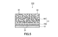
- FIG. 5 is a cross-sectional view showing the configuration of the negative electrode 213 in the modified example 3.
- the negative electrode active material layer 11 has a first active material layer 153 and a second active material layer 161.
- the first active material layer 153 contains the first active material 31 and does not contain the solid electrolyte 33.
- the first active material layer 152 may contain only the first active material 31 as the negative electrode active material. According to such a configuration, a sufficient discharge capacity of the first active material layer 153 can be secured. This contributes to the improvement of the energy density of the battery 100.
- the first active material layer 153 may be formed by forming an alloy-based active material on the surface of the negative electrode current collector 12 by a dry method.
- the dry method include thin film deposition and sputtering.
- Does not contain solid electrolyte 33 means that the solid electrolyte 33 is not intentionally added.
- the first active material layer 153 is thinner than the second active material layer 161. Therefore, the negative electrode 213 has an excellent balance between energy density and safety.
- Example 1 [Preparation of material A1 for the first active material layer]
- Graphite and Si were mixed in a mortar at a mass ratio of 4: 1 in a glove box having an Ar atmosphere with a dew point of ⁇ 60 ° C. or lower to obtain a mixture.
- a mixture of graphite and Si and a sulfide solid electrolyte were mixed at a mass ratio of 7: 3.
- material A1 was obtained.
- graphite and Si powdery ones were used.
- a copper foil was laminated on the layer of material A1.
- a laminate of a negative electrode current collector, a negative electrode active material layer and an electrolyte layer was obtained.
- metal In thickness 200 ⁇ m
- metal Li thickness 300 ⁇ m
- metal In thickness 200 ⁇ m
- the battery of Example 1 was produced by sealing the insulating outer cylinder using an insulating ferrule and blocking the inside of the insulating outer cylinder from the outside air atmosphere.
- the negative electrode of the battery of Example 1 had the structure described with reference to FIG.
- Example 2 [Preparation of material A2 for the first active material layer] Graphite and Si were mixed in a mortar at a mass ratio of 1: 1 in a glove box having an Ar atmosphere with a dew point of ⁇ 60 ° C. or lower to obtain a mixture. Then, a mixture of graphite and Si and a sulfide solid electrolyte were mixed at a mass ratio of 7: 3. As a result, material A2 was obtained.
- a battery of Example 2 was made in the same manner as in Example 1 except that 8 mg of material B2 was used in place of 5 mg of material B1 and 2 mg of material A2 was used in place of 5 mg of material A1.
- the negative electrode of the battery of Example 2 had the structure described with reference to FIG.
- Example 3 [Preparation of material A3 for the first active material layer] Si and the sulfide solid electrolyte were mixed at a mass ratio of 7: 3 in a glove box having an Ar atmosphere with a dew point of ⁇ 60 ° C. or lower. As a result, material A3 was obtained.
- a battery of Example 3 was made in the same manner as in Example 1 except that 9 mg of material B3 was used in place of 5 mg of material B1 and 1 mg of material A3 was used in place of 5 mg of material A1.
- the negative electrode of the battery of Example 3 had the structure described with reference to FIG.
- Example 4 [Preparation of material A4 for the first active material layer] Only Si was prepared as the material A4 in a glove box having an Ar atmosphere with a dew point of ⁇ 60 ° C. or lower.
- a battery of Example 4 was made in the same manner as in Example 1 except that 9 mg of material B4 was used in place of 5 mg of material B1 and 1 mg of material A4 was used in place of 5 mg of material A1.
- the negative electrode of the battery of Example 4 had the structure described with reference to FIG.
- Comparative Example 1 [Preparation of material a1 for the first active material layer] Graphite and a sulfide solid electrolyte were mixed at a mass ratio of 7: 3 in a glove box having an Ar atmosphere with a dew point of ⁇ 60 ° C. or lower. As a result, the material a1 was obtained.
- a battery of Comparative Example 1 was prepared in the same manner as in Example 1 except that 5 mg of material b1 was used in place of 5 mg of material B1 and 5 mg of material a1 was used in place of 5 mg of material A1.
- FIG. 6 is a cross-sectional view showing the configuration of the negative electrode 300 of the battery in Comparative Example 1.
- the negative electrode 300 has a negative electrode current collector 312 and a negative electrode active material layer 311.
- the negative electrode active material layer 311 has a first active material layer 350 and a second active material layer 360.
- the negative electrode current collector 312, the first active material layer 350, and the second active material layer 360 are laminated in this order.
- the first active material layer 350 contains only graphite as the negative electrode active material.
- the second active material layer 360 contains graphite and Si as the negative electrode active material.
- a battery of Comparative Example 2 was prepared in the same manner as in Example 1 except that 10 mg of material c1 was used in place of 5 mg of material B1 and 5 mg of material A1.
- FIG. 7 is a cross-sectional view showing the configuration of the negative electrode 301 of the battery in Comparative Example 2.
- the negative electrode 301 has a negative electrode current collector 312 and a negative electrode active material layer 311.
- the negative electrode active material layer 311 is provided on the negative electrode current collector 312.
- the negative electrode active material layer 311 contains graphite and Si as the negative electrode active material. Graphite and Si are uniformly distributed in the negative electrode active material layer 311.
- the battery was placed in a constant temperature bath at 25 ° C.
- Constant current charging was performed at a current value of 380 ⁇ A, which is a 0.05 C rate (20 hour rate) with respect to the theoretical capacity of the battery, and charging was completed at a voltage of ⁇ 0.62 V.
- the batteries of Comparative Examples 1 and 2 lost their battery functions during charging.
- Si which is an alloy-based active material
- the alloy-based active material expands due to the insertion of lithium ions into Si during charging, the expanded alloy-based active material penetrates the electrolyte layer, and the alloy-based active material is the lithium indium alloy, which is the positive electrode active material, and the inside. It is presumed that a short circuit occurred.
- the battery of the present disclosure can be used as, for example, an all-solid-state lithium secondary battery.
Abstract
This battery 100 comprises a positive electrode 220, a negative electrode 210, and an electrolyte layer 13 positioned between the positive electrode 220 and the negative electrode 210, the negative electrode 210 having a negative-electrode collector body 12 and a negative-electrode active material layer 11 positioned between the negative-electrode collector body 12 and the electrolyte layer 13, the negative-electrode active material layer 11 including a first active material layer 150 and a second active material layer 160 positioned between the first active material layer 150 and the electrolyte layer 13, the first active material layer 150 including a material alloyed with Li as a first active material 31, and the second active material layer 160 including a second active material 32 and a solid electrolyte 33 and not including the material alloyed with Li.
Description
本開示は、電池に関する。
This disclosure relates to batteries.
電池の負極には、負極活物質として主に炭素材料が使用されている。より高い電池容量を得るために、シリコンなどの合金系材料を負極活物質として使用することが検討されている。
Carbon material is mainly used as the negative electrode active material for the negative electrode of the battery. In order to obtain a higher battery capacity, it is considered to use an alloy-based material such as silicon as a negative electrode active material.
特許文献1には、Li、PおよびSを含む固体電解質と、負極活物質としての炭素材料と、負極活物質としての合金系材料との混合材料を負極活物質層に用いた全固体電池が開示されている。
Patent Document 1 describes an all-solid-state battery in which a mixed material of a solid electrolyte containing Li, P and S, a carbon material as a negative electrode active material, and an alloy-based material as a negative electrode active material is used for the negative electrode active material layer. It is disclosed.
従来技術においては、エネルギー密度と安全性とを両立することが望まれる。
In the conventional technology, it is desired to achieve both energy density and safety.
本開示は、
正極と、
負極と、
前記正極と前記負極との間に位置する固体電解質層と、
を備え、
前記負極は、負極集電体と、前記負極集電体と前記固体電解質層との間に位置する負極活物質層と、を有し、
前記負極活物質層は、第1活物質層と、前記第1活物質層と前記固体電解質層との間に位置する第2活物質層と、を含み、
前記第1活物質層は、Liと合金化する材料を第1活物質として含み、
前記第2活物質層は、第2活物質および固体電解質を含み、かつ、Liと合金化する材料を含まない、
電池を提供する。 This disclosure is
With the positive electrode
With the negative electrode
A solid electrolyte layer located between the positive electrode and the negative electrode,
With
The negative electrode has a negative electrode current collector and a negative electrode active material layer located between the negative electrode current collector and the solid electrolyte layer.
The negative electrode active material layer includes a first active material layer and a second active material layer located between the first active material layer and the solid electrolyte layer.
The first active material layer contains a material that alloys with Li as the first active material.
The second active material layer contains a second active material and a solid electrolyte, and does not contain a material that alloys with Li.
Provide batteries.
本開示によれば、エネルギー密度と安全性とを両立させることができる。
According to the present disclosure, both energy density and safety can be achieved at the same time.
(本開示の基礎となった知見)
合金系活物質が負極に含まれている場合、リチウムイオンの挿入反応および脱離反応により合金系活物質が膨張および収縮して負極の体積が大きく変化する。合金系活物質の粒子が大きい場合、膨張に伴って合金系活物質の粒子が絶縁層である固体電解質層を貫通する可能性もある。この場合、電池の機能が消失する。 (Knowledge on which this disclosure was based)
When the alloy-based active material is contained in the negative electrode, the alloy-based active material expands and contracts due to the insertion reaction and the desorption reaction of lithium ions, and the volume of the negative electrode changes significantly. When the particles of the alloy-based active material are large, the particles of the alloy-based active material may penetrate the solid electrolyte layer, which is an insulating layer, as the particles expand. In this case, the function of the battery is lost.
特に、固体電池においては、固体電解質層および負極活物質層が緻密な構造を有するので、固体電池には負極活物質の膨張を吸収するスペースが殆どない。固体電池には、負極活物質の膨張に関して、液体電解質を用いた電池よりも厳しい制約が課される。
In particular, in a solid-state battery, since the solid electrolyte layer and the negative electrode active material layer have a dense structure, the solid-state battery has almost no space for absorbing the expansion of the negative electrode active material. Solid-state batteries are subject to stricter restrictions on the expansion of the negative electrode active material than batteries using liquid electrolytes.
上記の問題を解決する1つの方法として、絶縁層である固体電解質層の厚さを増やすことが考えられる。しかし、固体電解質層は、電池のエネルギー密度に寄与しないので、固体電解質層の厚さを増やすと電池のエネルギー密度が低下する。
One way to solve the above problem is to increase the thickness of the solid electrolyte layer, which is the insulating layer. However, since the solid electrolyte layer does not contribute to the energy density of the battery, increasing the thickness of the solid electrolyte layer lowers the energy density of the battery.
このように、合金系活物質を用いた電池において、エネルギー密度と安全性との間には、トレードオフの関係がある。そのため、エネルギー密度と安全性とを両立させることが望まれている。
As described above, in a battery using an alloy-based active material, there is a trade-off relationship between energy density and safety. Therefore, it is desired to achieve both energy density and safety.
(本開示に係る一態様の概要)
本開示の第1態様に係る電池は、
正極と、
負極と、
前記正極と前記負極との間に位置する固体電解質層と、
を備え、
前記負極は、負極集電体と、前記負極集電体と前記固体電解質層との間に位置する負極活物質層と、を有し、
前記負極活物質層は、第1活物質層と、前記第1活物質層と前記固体電解質層との間に位置する第2活物質層と、を含み、
前記第1活物質層は、Liと合金化する材料を第1活物質として含み、
前記第2活物質層は、第2活物質および固体電解質を含み、かつ、Liと合金化する材料を含まない。 (Summary of one aspect of the present disclosure)
The battery according to the first aspect of the present disclosure is
With the positive electrode
With the negative electrode
A solid electrolyte layer located between the positive electrode and the negative electrode,
With
The negative electrode has a negative electrode current collector and a negative electrode active material layer located between the negative electrode current collector and the solid electrolyte layer.
The negative electrode active material layer includes a first active material layer and a second active material layer located between the first active material layer and the solid electrolyte layer.
The first active material layer contains a material that alloys with Li as the first active material.
The second active material layer contains a second active material and a solid electrolyte, and does not contain a material that alloys with Li.
第1態様によれば、第2活物質層が第1活物質層と電解質層との間の緩衝層として機能する。その結果、第1活物質が膨張して電解質層を貫通することを防止できる。また、第1活物質層には、Liと合金化する材料が含まれているので、電池のエネルギー密度が高まる。よって、本実施の形態によれば、エネルギー密度と安全性とを両立させることができる。
According to the first aspect, the second active material layer functions as a buffer layer between the first active material layer and the electrolyte layer. As a result, it is possible to prevent the first active material from expanding and penetrating the electrolyte layer. Further, since the first active material layer contains a material that alloys with Li, the energy density of the battery is increased. Therefore, according to the present embodiment, both energy density and safety can be achieved at the same time.
本開示の第2態様において、例えば、第1態様に係る電池では、前記第2活物質は、炭素材料を含んでいてもよい。充電時における炭素材料の膨張率は比較的小さいので、炭素材料を第2活物質として使用すれば、電池の安全性を高めることができる。
In the second aspect of the present disclosure, for example, in the battery according to the first aspect, the second active material may contain a carbon material. Since the expansion coefficient of the carbon material during charging is relatively small, the safety of the battery can be improved by using the carbon material as the second active material.
本開示の第3態様において、例えば、第2態様に係る電池では、前記炭素材料は、グラファイトを含んでいてもよい。グラファイトは、合金系活物質と比較して、リチウムイオンの挿入反応時の膨張率が小さいため、第2活物質として適している。
In the third aspect of the present disclosure, for example, in the battery according to the second aspect, the carbon material may contain graphite. Graphite is suitable as a second active material because it has a smaller expansion coefficient during the insertion reaction of lithium ions than an alloy-based active material.
本開示の第4態様において、例えば、第1から第3態様のいずれか1つに係る電池では、前記第1活物質は、シリコン、スズ、およびチタンからなる群より選択される少なくとも1つを含んでいてもよい。これらの材料を第1活物質として使用すれば、電池のエネルギー密度を高めることができる。
In the fourth aspect of the present disclosure, for example, in the battery according to any one of the first to third aspects, the first active material is at least one selected from the group consisting of silicon, tin, and titanium. It may be included. If these materials are used as the first active material, the energy density of the battery can be increased.
本開示の第5態様において、例えば、第1から第4態様のいずれか1つに係る電池では、前記第1活物質層は、前記第2活物質層よりも薄くてもよい。このような構成によれば、電池の安全性をさらに高めることができる。
In the fifth aspect of the present disclosure, for example, in the battery according to any one of the first to fourth aspects, the first active material layer may be thinner than the second active material layer. With such a configuration, the safety of the battery can be further enhanced.
本開示の第6態様において、例えば、第1から第5態様のいずれか1つに係る電池では、前記第1活物質層は、前記第2活物質を含まなくてもよい。このような構成によれば、第1活物質層の放電容量を十分に確保することができる。
In the sixth aspect of the present disclosure, for example, in the battery according to any one of the first to fifth aspects, the first active material layer does not have to contain the second active material. According to such a configuration, a sufficient discharge capacity of the first active material layer can be secured.
本開示の第7態様において、例えば、第6態様に係る電池では、前記第1活物質層は、前記固体電解質を含まなくてもよい。このような構成によれば、第1活物質層の放電容量を十分に確保することができる。
In the seventh aspect of the present disclosure, for example, in the battery according to the sixth aspect, the first active material layer does not have to contain the solid electrolyte. According to such a configuration, a sufficient discharge capacity of the first active material layer can be secured.
本開示の第8態様において、例えば、第1から第7態様のいずれか1つに係る電池では、前記固体電解質は、リチウムイオン伝導性を有していてもよい。このような構成によれば、負極活物質層のリチウムイオン伝導性を高めることができる。
In the eighth aspect of the present disclosure, for example, in the battery according to any one of the first to seventh aspects, the solid electrolyte may have lithium ion conductivity. According to such a configuration, the lithium ion conductivity of the negative electrode active material layer can be enhanced.
以下、本開示の実施形態について、図面を参照しながら説明する。本開示は、以下の実施形態に限定されない。
Hereinafter, embodiments of the present disclosure will be described with reference to the drawings. The present disclosure is not limited to the following embodiments.
(実施の形態)
図1は、実施の形態における電池100の概略構成を示す断面図である。電池100は、正極220と、負極210と、電解質層13と、を備える。 (Embodiment)
FIG. 1 is a cross-sectional view showing a schematic configuration of thebattery 100 according to the embodiment. The battery 100 includes a positive electrode 220, a negative electrode 210, and an electrolyte layer 13.
図1は、実施の形態における電池100の概略構成を示す断面図である。電池100は、正極220と、負極210と、電解質層13と、を備える。 (Embodiment)
FIG. 1 is a cross-sectional view showing a schematic configuration of the
正極220は、正極活物質層17および正極集電体18を有する。正極活物質層17は、電解質層13と正極集電体18との間に配置されている。正極活物質層17は、正極集電体18に電気的に接触している。
The positive electrode 220 has a positive electrode active material layer 17 and a positive electrode current collector 18. The positive electrode active material layer 17 is arranged between the electrolyte layer 13 and the positive electrode current collector 18. The positive electrode active material layer 17 is in electrical contact with the positive electrode current collector 18.
正極集電体18は、正極活物質層17から電力を集める機能を有する部材である。正極集電体18の材料としては、アルミニウム、アルミニウム合金、ステンレス、銅、ニッケルなどが挙げられる。正極集電体18は、アルミニウムまたはアルミニウム合金で作られていてもよい。正極集電体18の寸法、形状などは、電池100の用途に応じて適宜選択されうる。
The positive electrode current collector 18 is a member having a function of collecting electric power from the positive electrode active material layer 17. Examples of the material of the positive electrode current collector 18 include aluminum, aluminum alloy, stainless steel, copper, nickel and the like. The positive electrode current collector 18 may be made of aluminum or an aluminum alloy. The dimensions, shape, and the like of the positive electrode current collector 18 can be appropriately selected according to the application of the battery 100.
正極活物質層17は、正極活物質と固体電解質とを含む。正極活物質としては、リチウムイオンなどの金属イオンを吸蔵および放出する特性を有する材料が用いられうる。正極活物質としては、リチウム含有遷移金属酸化物、遷移金属フッ化物、ポリアニオン材料、フッ素化ポリアニオン材料、遷移金属硫化物、遷移金属オキシ硫化物、遷移金属オキシ窒化物などが用いられうる。特に、正極活物質として、リチウム含有遷移金属酸化物を用いた場合には、製造コストを安くでき、平均放電電圧を高めることができる。
The positive electrode active material layer 17 contains a positive electrode active material and a solid electrolyte. As the positive electrode active material, a material having a property of occluding and releasing metal ions such as lithium ions can be used. As the positive electrode active material, a lithium-containing transition metal oxide, a transition metal fluoride, a polyanion material, a fluorinated polyanion material, a transition metal sulfide, a transition metal oxysulfide, a transition metal oxynitride, or the like can be used. In particular, when a lithium-containing transition metal oxide is used as the positive electrode active material, the manufacturing cost can be reduced and the average discharge voltage can be increased.
正極活物質は、Liと、Mn、Co、NiおよびAlからなる群より選択される少なくとも1種の元素とを含んでいてもよい。そのような材料としては、Li(NiCoAl)O2、Li(NiCoMn)O2、LiCoO2などが挙げられる。
The positive electrode active material may contain Li and at least one element selected from the group consisting of Mn, Co, Ni and Al. Examples of such a material include Li (NiCoAl) O 2 , Li (NiCoMn) O 2 , LiCoO 2, and the like.
正極活物質は、例えば、粒子の形状を有する。正極活物質の粒子の形状は特に限定されない。正極活物質の粒子の形状は、針状、球状、楕円球状または鱗片状でありうる。
The positive electrode active material has, for example, the shape of particles. The shape of the particles of the positive electrode active material is not particularly limited. The shape of the particles of the positive electrode active material can be needle-like, spherical, elliptical spherical or scaly.
正極活物質の粒子のメジアン径は、0.1μm以上かつ100μm以下であってもよい。正極活物質の粒子のメジアン径が0.1μm以上の場合、正極220において、正極活物質と固体電解質とが、良好な分散状態を形成しうる。この結果、電池100の充放電特性が向上する。正極活物質の粒子のメジアン径が100μm以下の場合、正極活物質の粒子内のリチウム拡散が速くなる。このため、電池100が高出力で動作しうる。
The median diameter of the particles of the positive electrode active material may be 0.1 μm or more and 100 μm or less. When the median diameter of the particles of the positive electrode active material is 0.1 μm or more, the positive electrode active material and the solid electrolyte can form a good dispersed state in the positive electrode 220. As a result, the charge / discharge characteristics of the battery 100 are improved. When the median diameter of the particles of the positive electrode active material is 100 μm or less, the lithium diffusion in the particles of the positive electrode active material becomes fast. Therefore, the battery 100 can operate at a high output.
正極220の固体電解質としては、硫化物固体電解質、酸化物固体電解質、ハロゲン化物固体電解質、高分子固体電解質および錯体水素化物固体電解質からなる群より選ばれる少なくとも1つを用いてもよい。酸化物固体電解質は、優れた高電位安定性を有する。酸化物固体電解質を用いることで、電池100の充放電効率をより向上させることができる。
As the solid electrolyte of the positive electrode 220, at least one selected from the group consisting of a sulfide solid electrolyte, an oxide solid electrolyte, a halide solid electrolyte, a polymer solid electrolyte and a complex hydride solid electrolyte may be used. The oxide solid electrolyte has excellent high potential stability. By using the oxide solid electrolyte, the charge / discharge efficiency of the battery 100 can be further improved.
正極220において、正極活物質と固体電解質との体積比率「v1:100-v1」について、30≦v1≦95が満たされてもよい。30≦v1が満たされる場合、電池100のエネルギー密度が十分に確保される。また、v1≦95が満たされる場合、高出力での動作が可能となる。
In the positive electrode 220, 30 ≦ v1 ≦ 95 may be satisfied with respect to the volume ratio “v1: 100−v1” of the positive electrode active material and the solid electrolyte. When 30 ≦ v1 is satisfied, the energy density of the battery 100 is sufficiently secured. Further, when v1 ≦ 95 is satisfied, operation at high output becomes possible.
正極220の厚みは、10μm以上かつ500μm以下であってもよい。正極220の厚みが10μm以上である場合、電池100のエネルギー密度が十分に確保される。正極220の厚みが500μm以下である場合、高出力での動作が可能となる。
The thickness of the positive electrode 220 may be 10 μm or more and 500 μm or less. When the thickness of the positive electrode 220 is 10 μm or more, the energy density of the battery 100 is sufficiently secured. When the thickness of the positive electrode 220 is 500 μm or less, operation at high output is possible.
正極220に含まれた固体電解質の形状が粒子状(例えば、球状)の場合、固体電解質の粒子群のメジアン径は、100μm以下であってもよい。メジアン径が100μm以下の場合、正極活物質と固体電解質とが、正極220において良好な分散状態を形成しうる。このため、電池100の充放電特性が向上する。
When the shape of the solid electrolyte contained in the positive electrode 220 is particulate (for example, spherical), the median diameter of the particle group of the solid electrolyte may be 100 μm or less. When the median diameter is 100 μm or less, the positive electrode active material and the solid electrolyte can form a good dispersed state in the positive electrode 220. Therefore, the charge / discharge characteristics of the battery 100 are improved.
本明細書において、「メジアン径」は、体積基準の粒度分布における累積体積が50%に等しい場合の粒径を意味する。体積基準の粒度分布は、例えば、レーザー回折式測定装置または画像解析装置により測定される。
In the present specification, the "median diameter" means the particle size when the cumulative volume in the volume-based particle size distribution is equal to 50%. The volume-based particle size distribution is measured, for example, by a laser diffraction measuring device or an image analyzer.
電解質層13は、正極220と負極210との間に位置している。電解質層13は、電解質を含む層である。電解質は、例えば、固体電解質である。電解質層13は、固体電解質層でありうる。
The electrolyte layer 13 is located between the positive electrode 220 and the negative electrode 210. The electrolyte layer 13 is a layer containing an electrolyte. The electrolyte is, for example, a solid electrolyte. The electrolyte layer 13 can be a solid electrolyte layer.
電解質層13は、固体電解質として、ハロゲン化物固体電解質、硫化物固体電解質、酸化物固体電解質、高分子固体電解質および錯体水素化物固体電解質からなる群より選ばれる少なくとも1つを含んでいてもよい。
The electrolyte layer 13 may contain at least one selected from the group consisting of a halide solid electrolyte, a sulfide solid electrolyte, an oxide solid electrolyte, a polymer solid electrolyte and a complex hydride solid electrolyte as the solid electrolyte.
電解質層13は、多層構造を有していてもよい。この場合、負極220に接する層の材料の組成は、正極220に接する層の材料の組成と異なっていてもよい。負極220に接する層は、還元耐性に優れた硫化物固体電解質で作られていてもよい。正極220に接する層は、酸化耐性に優れるハロゲン化物固体電解質で作られていてもよい。
The electrolyte layer 13 may have a multi-layer structure. In this case, the composition of the material of the layer in contact with the negative electrode 220 may be different from the composition of the material of the layer in contact with the positive electrode 220. The layer in contact with the negative electrode 220 may be made of a sulfide solid electrolyte having excellent reduction resistance. The layer in contact with the positive electrode 220 may be made of a halide solid electrolyte having excellent oxidation resistance.
電解質層13に含まれた固体電解質は、例えば、粒子の形状を有する。粒子の形状は特に限定されず、例えば、針状、球状または楕円球状である。
The solid electrolyte contained in the electrolyte layer 13 has, for example, the shape of particles. The shape of the particles is not particularly limited, and is, for example, needle-shaped, spherical, or elliptical spherical.
電解質層13の厚みは、1μm以上かつ300μm以下であってもよい。電解質層13の厚みが1μm以上の場合には、正極220と負極210との間の短絡を確実に防止できる。電解質層13の厚みが300μm以下の場合には、高出力での動作を実現しうる。
The thickness of the electrolyte layer 13 may be 1 μm or more and 300 μm or less. When the thickness of the electrolyte layer 13 is 1 μm or more, a short circuit between the positive electrode 220 and the negative electrode 210 can be reliably prevented. When the thickness of the electrolyte layer 13 is 300 μm or less, operation at high output can be realized.
負極210は、負極活物質層11および負極集電体12を備える。負極活物質層11は、電解質層13と負極集電体12との間に配置されている。負極活物質層11は、負極集電体12に電気的に接触している。
The negative electrode 210 includes a negative electrode active material layer 11 and a negative electrode current collector 12. The negative electrode active material layer 11 is arranged between the electrolyte layer 13 and the negative electrode current collector 12. The negative electrode active material layer 11 is in electrical contact with the negative electrode current collector 12.
負極集電体12は、負極活物質層11から電力を集める機能を有する部材である。負極集電体12の材料としては、アルミニウム、アルミニウム合金、ステンレス、銅、ニッケルなどが挙げられる。負極集電体12は、ニッケルで作られていてもよい。負極集電体12の寸法、形状などは、電池100の用途に応じて適宜選択されうる。
The negative electrode current collector 12 is a member having a function of collecting electric power from the negative electrode active material layer 11. Examples of the material of the negative electrode current collector 12 include aluminum, aluminum alloy, stainless steel, copper, nickel and the like. The negative electrode current collector 12 may be made of nickel. The dimensions, shape, and the like of the negative electrode current collector 12 can be appropriately selected according to the application of the battery 100.
図2は、負極210の詳細な構成を示す断面図である。負極活物質層11は、第1活物質層150および第2活物質層160を含む。第2活物質層160は、第1活物質層150と電解質層13との間に位置している。第1活物質層150は、Liと合金化する材料を第1活物質31として含む。第2活物質層160は、第2活物質32および固体電解質33を含み、かつ、Liと合金化する材料を含まない。第1活物質31は、負極集電体12の近傍に偏在している。
FIG. 2 is a cross-sectional view showing a detailed configuration of the negative electrode 210. The negative electrode active material layer 11 includes a first active material layer 150 and a second active material layer 160. The second active material layer 160 is located between the first active material layer 150 and the electrolyte layer 13. The first active material layer 150 contains a material that alloys with Li as the first active material 31. The second active material layer 160 contains the second active material 32 and the solid electrolyte 33, and does not contain a material that alloys with Li. The first active material 31 is unevenly distributed in the vicinity of the negative electrode current collector 12.
負極活物質層11が上記構造を有している場合、以下の効果が得られる。すなわち、リチウムイオンの挿入反応の際に第1活物質層150に含まれた第1活物質31が膨張したとしても、Liと合金化する材料を含まない第2活物質層160が第1活物質層150と電解質層13との間の緩衝層として機能する。その結果、第1活物質31が膨張して電解質層13を貫通することを防止できる。また、第1活物質層150には、Liと合金化する材料が含まれているので、電池100のエネルギー密度が高まる。よって、本実施の形態によれば、エネルギー密度と安全性とを両立させることができる。
When the negative electrode active material layer 11 has the above structure, the following effects can be obtained. That is, even if the first active material 31 contained in the first active material layer 150 expands during the lithium ion insertion reaction, the second active material layer 160 containing no material to alloy with Li is the first active material layer 160. It functions as a buffer layer between the material layer 150 and the electrolyte layer 13. As a result, it is possible to prevent the first active material 31 from expanding and penetrating the electrolyte layer 13. Further, since the first active material layer 150 contains a material that alloys with Li, the energy density of the battery 100 is increased. Therefore, according to the present embodiment, both energy density and safety can be achieved at the same time.
「Liと合金化する材料を含まない」とは、Liと合金化する材料が意図的に添加されていないことを意味する。例えば、第2活物質層160に含まれた活物質の全質量に対してLiと合金化する材料の質量が1%以下であるとき、Liと合金化する材料が第2活物質層160に意図的に添加されていないとみなされる。
"Does not contain the material that alloys with Li" means that the material that alloys with Li is not intentionally added. For example, when the mass of the material alloying with Li is 1% or less with respect to the total mass of the active material contained in the second active material layer 160, the material alloying with Li is added to the second active material layer 160. It is considered not to be added intentionally.
本実施の形態において、第1活物質層150は、負極集電体12に接している。ただし、第1活物質層150は、負極集電体12から離れていてもよい。第1活物質層150と負極集電体12との間に別の層が設けられていてもよい。第1活物質層150は、第2活物質層160にも接している。ただし、第1活物質層150は、第2活物質層160から離れていてもよい。第1活物質層150と第2活物質層160との間に別の層が設けられていてもよい。第2活物質層160は、電解質層13に接している。
In the present embodiment, the first active material layer 150 is in contact with the negative electrode current collector 12. However, the first active material layer 150 may be separated from the negative electrode current collector 12. Another layer may be provided between the first active material layer 150 and the negative electrode current collector 12. The first active material layer 150 is also in contact with the second active material layer 160. However, the first active material layer 150 may be separated from the second active material layer 160. Another layer may be provided between the first active material layer 150 and the second active material layer 160. The second active material layer 160 is in contact with the electrolyte layer 13.
第1活物質31および第2活物質32は、ともに、リチウムイオンを吸蔵および放出する特性を有する。第1活物質31の理論容量(単位:mAh/g)は、第2活物質32の理論容量よりも大きい。充電時における第1活物質31の膨張率(体積膨張率)は、充電時における第2活物質32の膨張率よりも大きい。
Both the first active material 31 and the second active material 32 have the property of occluding and releasing lithium ions. The theoretical capacity (unit: mAh / g) of the first active material 31 is larger than the theoretical capacity of the second active material 32. The expansion coefficient (volume expansion coefficient) of the first active material 31 during charging is larger than the expansion rate of the second active material 32 during charging.
第1活物質31は、例えば、シリコン、スズ、およびチタンからなる群より選択される少なくとも1つを含む。これらは、Liと合金化する材料であり、いずれも炭素材料よりも高い理論容量を有する。これらの材料を第1活物質31として使用すれば、電池100のエネルギー密度を高めることができる。Liと合金化する材料は、典型的には、金属または半金属である。金属または半金属は、単体であってもよい。Liと合金化する材料が単体の金属または半金属であることは必須ではない。Liと合金化する材料は、Liと合金化する元素を含む化合物であってもよい。そのような化合物としては、SiOx(0<x<2)で表される酸化シリコン、SnOまたはSnO2で表される酸化スズなどが挙げられる。
The first active material 31 contains, for example, at least one selected from the group consisting of silicon, tin, and titanium. These are materials that alloy with Li and all have a higher theoretical capacity than carbon materials. If these materials are used as the first active material 31, the energy density of the battery 100 can be increased. The material to alloy with Li is typically a metal or metalloid. The metal or metalloid may be a simple substance. It is not essential that the material alloying with Li is a simple metal or a metalloid. The material to be alloyed with Li may be a compound containing an element to be alloyed with Li. Such compounds, silicon oxide represented by SiOx (0 <x <2) , tin oxide represented by SnO or SnO 2 and the like.
第2活物質32は、Liと合金化する材料を除く、炭素材料、金属材料、酸化物、窒化物、錫化合物、珪素化合物およびチタン化合物からなる群より選ばれる少なくとも1つでありうる。LTO(Li4Ti5O12)のような化合物は、第2活物質32として使用可能である。金属材料は、単体の金属であってもよく、合金であってもよい。金属材料としては、リチウム金属が挙げられる。炭素材料としては、グラファイト、コークス、黒鉛化途上炭素、炭素繊維、球状炭素、非晶質炭素などが挙げられる。充電時における炭素材料の膨張率は比較的小さいので、炭素材料を第2活物質32として使用すれば、電池100の安全性を高めることができる。第2活物質32は、典型的には、グラファイトを含む。グラファイトは、合金系活物質と比較して、リチウムイオンの挿入反応時の膨張率が小さいため、第2活物質32として適している。
The second active material 32 may be at least one selected from the group consisting of carbon materials, metal materials, oxides, nitrides, tin compounds, silicon compounds and titanium compounds, excluding materials that alloy with Li. Compounds such as LTO (Li 4 Ti 5 O 12 ) can be used as the second active material 32. The metal material may be a simple substance metal or an alloy. Examples of the metal material include lithium metal. Examples of the carbon material include graphite, coke, graphitizing carbon, carbon fiber, spherical carbon, amorphous carbon and the like. Since the expansion coefficient of the carbon material during charging is relatively small, the safety of the battery 100 can be enhanced by using the carbon material as the second active material 32. The second active material 32 typically contains graphite. Graphite is suitable as the second active material 32 because it has a smaller expansion coefficient during the insertion reaction of lithium ions than the alloy-based active material.
「合金系活物質」は、リチウムと合金化する活物質を意味する。「合金系材料」は、リチウムと合金化する材料を意味する。
"Alloy-based active material" means an active material that alloys with lithium. "Alloy-based material" means a material that alloys with lithium.
第1活物質31および第2活物質32は、ともに、粒子の形状を有していてもよい。第1活物質31の粒子および第2活物質32の粒子は、球状、楕円球状、繊維状または鱗片状の形状を有していてもよい。
Both the first active material 31 and the second active material 32 may have the shape of particles. The particles of the first active material 31 and the particles of the second active material 32 may have a spherical shape, an elliptical spherical shape, a fibrous shape, or a scaly shape.
本実施の形態において、第1活物質層150は、第1活物質31および第2活物質32の両方を含んでいる。これにより、充放電に伴う第1活物質層150と第2活物質層160との間の膨張率の差を小さくすることができる。第1活物質層150において、第1活物質31の質量M1に対する第2活物質32の質量M2の比率(M2/M1)は、例えば、0より大きく20以下の範囲にある。第1活物質31の質量M1は、Liと合金化する元素以外の元素(酸素など)を無視した場合の質量である。
In the present embodiment, the first active material layer 150 contains both the first active material 31 and the second active material 32. As a result, the difference in expansion coefficient between the first active material layer 150 and the second active material layer 160 due to charging and discharging can be reduced. In the first active material layer 150, the ratio (M2 / M1) of the mass M2 of the second active material 32 to the mass M1 of the first active material 31 is, for example, greater than 0 and in the range of 20 or less. The mass M1 of the first active material 31 is the mass when elements other than the element alloying with Li (oxygen and the like) are ignored.
固体電解質33は、第1活物質層150にも含まれている。このような構成によれば、第1活物質層150のイオン伝導性を向上させることができる。第1活物質層150に含まれた固体電解質の組成は、第2活物質層160に含まれた固体電解質の組成と同一であってもよく、異なっていてもよい。
The solid electrolyte 33 is also contained in the first active material layer 150. According to such a configuration, the ionic conductivity of the first active material layer 150 can be improved. The composition of the solid electrolyte contained in the first active material layer 150 may be the same as or different from the composition of the solid electrolyte contained in the second active material layer 160.
第2活物質層160は、負極活物質として、Liと合金化する材料以外の材料のみを含んでいてもよい。このような構成によれば、電池100の安全性がより高まる。
The second active material layer 160 may contain only a material other than the material alloying with Li as the negative electrode active material. According to such a configuration, the safety of the battery 100 is further enhanced.
第1活物質層150および第2活物質層160のそれぞれの厚さは特に限定されない。図2の例によれば、第1活物質層150および第2活物質層160は、例えば、等しい厚さを有する。ただし、第1活物質層150は、第2活物質層160よりも厚くてもよい。第1活物質層150は、第2活物質層160よりも薄くてもよい。
The thickness of each of the first active material layer 150 and the second active material layer 160 is not particularly limited. According to the example of FIG. 2, the first active material layer 150 and the second active material layer 160 have, for example, the same thickness. However, the first active material layer 150 may be thicker than the second active material layer 160. The first active material layer 150 may be thinner than the second active material layer 160.
第1活物質層150および第2活物質層160のそれぞれの放電容量は特に限定されない。第1活物質層150および第2活物質層160は、例えば、等しい放電容量を有する。
The discharge capacities of the first active material layer 150 and the second active material layer 160 are not particularly limited. The first active material layer 150 and the second active material layer 160 have, for example, equal discharge capacities.
固体電解質33は、リチウムイオン伝導性を有する。固体電解質33が負極活物質層11に固体電解質33が含まれていると、負極活物質層11のリチウムイオン伝導性を高めることができる。
The solid electrolyte 33 has lithium ion conductivity. When the solid electrolyte 33 contains the solid electrolyte 33 in the negative electrode active material layer 11, the lithium ion conductivity of the negative electrode active material layer 11 can be enhanced.
固体電解質33としては、硫化物固体電解質、酸化物固体電解質、ハロゲン化物固体電解質、高分子固体電解質および錯体水素化物固体電解質からなる群より選ばれる少なくとも1つが使用されうる。
As the solid electrolyte 33, at least one selected from the group consisting of a sulfide solid electrolyte, an oxide solid electrolyte, a halide solid electrolyte, a polymer solid electrolyte and a complex hydride solid electrolyte can be used.
硫化物固体電解質としては、Li2S-P2S5、Li2S-SiS2、Li2S-B2S3、Li2S-GeS2、Li3.25Ge0.25P0.75S4、Li10GeP2S12などが用いられうる。これらに、LiX、Li2O、MOq、LipMOqなどが添加されてもよい。ここで、「LiX」における元素Xは、F、Cl、Br、およびIからなる群より選択される少なくとも1種の元素である。「MOq」および「LipMOq」における元素Mは、P、Si、Ge、B、Al、Ga、In、Fe、およびZnからなる群より選択される少なくとも1種の元素である。「MOq」および「LipMOq」におけるpおよびqは、それぞれ独立な自然数である。
Examples of the sulfide solid electrolyte include Li 2 SP 2 S 5 , Li 2 S-SiS 2 , Li 2 SB 2 S 3 , Li 2 S-GeS 2 , Li 3.25 Ge 0.25 P 0.75 S 4 , Li 10 GeP 2 S 12 and the like can be used. These, LiX, Li 2 O, MO q, like Li p MO q may be added. Here, the element X in "LiX" is at least one element selected from the group consisting of F, Cl, Br, and I. The element M in "MO q " and "Li p MO q " is at least one element selected from the group consisting of P, Si, Ge, B, Al, Ga, In, Fe, and Zn. P and q in "MO q " and "Li p MO q " are independent natural numbers, respectively.
酸化物固体電解質としては、例えば、LiTi2(PO4)3およびその元素置換体を代表とするNASICON型固体電解質、(LaLi)TiO3系のペロブスカイト型固体電解質、Li14ZnGe4O16、Li4SiO4、LiGeO4およびその元素置換体を代表とするLISICON型固体電解質、Li7La3Zr2O12およびその元素置換体を代表とするガーネット型固体電解質、Li3NおよびそのH置換体、Li3PO4およびそのN置換体、LiBO2、Li3BO3などのLi-B-O化合物を含むベース材料にLi2SO4、Li2CO3などの材料が添加されたガラスまたはガラスセラミックスなどが用いられうる。
Examples of the oxide solid electrolyte include a NASICON type solid electrolyte typified by LiTi 2 (PO 4 ) 3 and its elemental substituent, a (LaLi) TiO 3 based perovskite type solid electrolyte, Li 14 ZnGe 4 O 16 , Li. 4 SiO 4 , LiGeO 4 and LISION type solid electrolyte typified by its element substitution product, Li 7 La 3 Zr 2 O 12 and garnet type solid electrolyte typified by its element substitution product, Li 3 N and its H substitution product , Li 3 PO 4 and its N-substituted products, glass or glass in which materials such as Li 2 SO 4 and Li 2 CO 3 are added to a base material containing Li-BO compounds such as Li BO 2 and Li 3 BO 3. Ceramics and the like can be used.
高分子固体電解質としては、例えば、高分子化合物と、リチウム塩との化合物が用いられうる。高分子化合物はエチレンオキシド構造を有していてもよい。エチレンオキシド構造を有することで、高分子化合物はリチウム塩を多く含有することができるので、イオン導電率をより高めることができる。リチウム塩としては、LiPF6、LiBF4、LiSbF6、LiAsF6、LiSO3CF3、LiN(SO2CF3)2、LiN(SO2C2F5)2、LiN(SO2CF3)(SO2C4F9)、LiC(SO2CF3)3などが使用されうる。リチウム塩として、これらから選択される1種のリチウム塩が単独で使用されてもよいし、これらから選択される2種以上のリチウム塩の混合物が使用されてもよい。
As the polymer solid electrolyte, for example, a compound of a polymer compound and a lithium salt can be used. The polymer compound may have an ethylene oxide structure. By having an ethylene oxide structure, the polymer compound can contain a large amount of lithium salts, so that the ionic conductivity can be further increased. The lithium salt, LiPF 6, LiBF 4, LiSbF 6, LiAsF 6, LiSO 3 CF 3, LiN (SO 2 CF 3) 2, LiN (SO 2 C 2 F 5) 2, LiN (SO 2 CF 3) ( SO 2 C 4 F 9 ), LiC (SO 2 CF 3 ) 3 and the like can be used. As the lithium salt, one lithium salt selected from these may be used alone, or a mixture of two or more lithium salts selected from these may be used.
錯体水素化物固体電解質としては、例えば、LiBH4-LiI、LiBH4-P2S5などが用いられうる。
As the complex hydride solid electrolyte, for example, LiBH 4- LiI, LiBH 4- P 2 S 5 and the like can be used.
ハロゲン化物固体電解質は、ハロゲンを含む固体電解質である。ハロゲン化物固体電解質は、例えば、下記の組成式(1)により表される。組成式(4)において、α、β、およびγは、それぞれ独立して、0より大きい値である。Mは、Li以外の金属元素および半金属元素からなる群より選択される少なくとも1つの元素を含む。Xは、F、Cl、Br、およびIからなる群より選択される少なくとも1つを含む。
The halide solid electrolyte is a solid electrolyte containing halogen. The halide solid electrolyte is represented by, for example, the following composition formula (1). In the composition formula (4), α, β, and γ are independently larger than 0. M contains at least one element selected from the group consisting of metallic elements other than Li and metalloid elements. X comprises at least one selected from the group consisting of F, Cl, Br, and I.
LiαMβXγ・・・(1)
Li α M β X γ・ ・ ・ (1)
半金属元素は、B、Si、Ge、As、Sb、およびTeを含む。金属元素は、水素を除く周期表1族から12族に含まれる全ての元素、ならびに、B、Si、Ge、As、Sb、Te、C、N、P、O、S、およびSeを除く13族から16族に含まれる全ての元素を含む。金属元素は、ハロゲンまたはハロゲン化合物と無機化合物を形成した際にカチオンとなりうる元素群である。
Metalloid elements include B, Si, Ge, As, Sb, and Te. Metal elements include all elements included in groups 1 to 12 of the periodic table except hydrogen, and 13 excluding B, Si, Ge, As, Sb, Te, C, N, P, O, S, and Se. Includes all elements from groups to groups 16. A metal element is a group of elements that can become cations when an inorganic compound is formed with a halogen or a halogen compound.
ハロゲン化物固体電解質として、Li3YX6、Li2MgX4、Li2FeX4、Li(Al,Ga,In)X4、Li3(Al,Ga,In)X6などが用いられうる。
As the halide solid electrolyte, Li 3 YX 6 , Li 2 MgX 4 , Li 2 FeX 4 , Li (Al, Ga, In) X 4 , Li 3 (Al, Ga, In) X 6 and the like can be used.
本開示において、式中の元素を「(Al,Ga,In)」のように表すとき、この表記は、括弧内の元素群より選択される少なくとも1種の元素を示す。すなわち、「(Al,Ga,In)」は、「Al、Ga、およびInからなる群より選択される少なくとも1種」と同義である。他の元素の場合でも同様である。ハロゲン化物固体電解質は、優れたイオン伝導性を示す。
In the present disclosure, when an element in the formula is expressed as "(Al, Ga, In)", this notation indicates at least one element selected from the element group in parentheses. That is, "(Al, Ga, In)" is synonymous with "at least one selected from the group consisting of Al, Ga, and In". The same applies to other elements. Halide solid electrolytes exhibit excellent ionic conductivity.
固体電解質33は、無機固体電解質であってもよい。無機固体電解質は電気化学的な安定性に優れているので、固体電解質33に適している。無機固体電解質としては、上記したように、硫化物固体電解質、酸化物固体電解質、ハロゲン化物固体電解質および錯体水素化物固体電解質が挙げられる。固体電解質33は、硫化物固体電解質を含んでいてもよく、硫化物固体電解質からなっていてもよい。硫化物固体電解質は還元耐性に優れているので、負極活物質層11に用いられる固体電解質として適している。硫化物固体電解質は柔軟性に富むので、硫化物固体電解質が負極活物質層11に含まれていると、合金系活物質の膨張および収縮を硫化物固体電解質によって吸収できる可能性がある。
The solid electrolyte 33 may be an inorganic solid electrolyte. Since the inorganic solid electrolyte is excellent in electrochemical stability, it is suitable for the solid electrolyte 33. Examples of the inorganic solid electrolyte include a sulfide solid electrolyte, an oxide solid electrolyte, a halide solid electrolyte, and a complex hydride solid electrolyte, as described above. The solid electrolyte 33 may contain a sulfide solid electrolyte or may be composed of a sulfide solid electrolyte. Since the sulfide solid electrolyte has excellent reduction resistance, it is suitable as a solid electrolyte used for the negative electrode active material layer 11. Since the sulfide solid electrolyte is highly flexible, if the sulfide solid electrolyte is contained in the negative electrode active material layer 11, the expansion and contraction of the alloy-based active material may be absorbed by the sulfide solid electrolyte.
第1活物質31および第2活物質32は、それぞれ、粒子の形状を有していてもよい。以下において、「負極活物質の粒子」は、第1活物質31の粒子および第2活物質32の粒子の一方または両方を意味する。
The first active material 31 and the second active material 32 may each have a particle shape. In the following, the “particle of the negative electrode active material” means one or both of the particles of the first active material 31 and the particles of the second active material 32.
負極活物質の粒子のメジアン径は、0.1μm以上かつ100μm以下であってもよい。負極活物質の粒子のメジアン径が0.1μm以上である場合、負極210において、負極活物質の粒子と固体電解質とが、良好な分散状態を形成できる。これにより、電池100の充放電特性が向上する。また、負極活物質の粒子のメジアン径が100μm以下である場合、負極活物質の粒子内のリチウム拡散が速くなる。このため、電池100が高出力で動作しうる。
The median diameter of the particles of the negative electrode active material may be 0.1 μm or more and 100 μm or less. When the median diameter of the particles of the negative electrode active material is 0.1 μm or more, the particles of the negative electrode active material and the solid electrolyte can form a good dispersed state in the negative electrode 210. This improves the charge / discharge characteristics of the battery 100. Further, when the median diameter of the particles of the negative electrode active material is 100 μm or less, the lithium diffusion in the particles of the negative electrode active material becomes fast. Therefore, the battery 100 can operate at a high output.
負極活物質の粒子のメジアン径は、負極210に含まれた固体電解質33の粒子のメジアン径よりも、大きくてもよい。これにより、負極活物質と固体電解質33との良好な分散状態を形成できる。
The median diameter of the particles of the negative electrode active material may be larger than the median diameter of the particles of the solid electrolyte 33 contained in the negative electrode 210. As a result, a good dispersed state of the negative electrode active material and the solid electrolyte 33 can be formed.
負極210における負極活物質と固体電解質33との体積比率が「v2:100-v2」で表されるとき、負極活物質の体積比率v2は、30≦v2≦95を満たしてもよい。30≦v2が満たされる場合、電池100のエネルギー密度が十分に確保される。また、v2≦95が満たされる場合、高出力での動作が可能となる。
When the volume ratio of the negative electrode active material to the solid electrolyte 33 in the negative electrode 210 is represented by "v2: 100-v2", the volume ratio v2 of the negative electrode active material may satisfy 30 ≦ v2 ≦ 95. When 30 ≦ v2 is satisfied, the energy density of the battery 100 is sufficiently secured. Further, when v2 ≦ 95 is satisfied, operation at high output becomes possible.
負極210の厚みは、10μm以上かつ500μm以下であってもよい。負極210の厚みが10μm以上である場合、電池100のエネルギー密度が十分に確保される。負極210の厚みが500μm以下である場合、高出力での動作が可能となる。
The thickness of the negative electrode 210 may be 10 μm or more and 500 μm or less. When the thickness of the negative electrode 210 is 10 μm or more, the energy density of the battery 100 is sufficiently secured. When the thickness of the negative electrode 210 is 500 μm or less, operation at high output is possible.
正極活物質層17と電解質層13と負極活物質層11とのうちの少なくとも1つには、リチウムイオンの授受を容易にし、電池の出力特性を向上する目的で、非水電解液、ゲル電解質またはイオン液体が含まれていてもよい。
A non-aqueous electrolyte solution or a gel electrolyte is applied to at least one of the positive electrode active material layer 17, the electrolyte layer 13, and the negative electrode active material layer 11 for the purpose of facilitating the transfer of lithium ions and improving the output characteristics of the battery. Alternatively, an ionic liquid may be contained.
非水電解液は、非水溶媒と非水溶媒に溶けたリチウム塩とを含む。非水溶媒としては、環状炭酸エステル溶媒、鎖状炭酸エステル溶媒、環状エーテル溶媒、鎖状エーテル溶媒、環状エステル溶媒、鎖状エステル溶媒、フッ素溶媒などが挙げられる。環状炭酸エステル溶媒としては、エチレンカーボネート、プロピレンカーボネート、ブチレンカーボネートなどが挙げられる。鎖状炭酸エステル溶媒としては、ジメチルカーボネート、エチルメチルカーボネート、ジエチルカーボネートなどが挙げられる。環状エーテル溶媒としては、テトラヒドロフラン、1,4-ジオキサン、1,3-ジオキソランなどが挙げられる。鎖状エーテル溶媒としては、1,2-ジメトキシエタン、1,2-ジエトキシエタンなどが挙げられる。環状エステル溶媒としては、γ-ブチロラクトンなどが挙げられる。鎖状エステル溶媒としては、酢酸メチルなどが挙げられる。フッ素溶媒としては、フルオロエチレンカーボネート、フルオロプロピオン酸メチル、フルオロベンゼン、フルオロエチルメチルカーボネート、フルオロジメチレンカーボネートなどが挙げられる。非水溶媒として、これらから選択される1種の非水溶媒が単独で使用されてもよいし、これらから選択される2種以上の非水溶媒の混合物が使用されてもよい。非水電解液には、フルオロエチレンカーボネート、フルオロプロピオン酸メチル、フルオロベンゼン、フルオロエチルメチルカーボネート、およびフルオロジメチレンカーボネートからなる群より選択される少なくとも1種のフッ素溶媒が含まれていてもよい。
The non-aqueous electrolyte solution contains a non-aqueous solvent and a lithium salt dissolved in the non-aqueous solvent. Examples of the non-aqueous solvent include a cyclic carbonate solvent, a chain carbonate solvent, a cyclic ether solvent, a chain ether solvent, a cyclic ester solvent, a chain ester solvent, and a fluorine solvent. Examples of the cyclic carbonate solvent include ethylene carbonate, propylene carbonate, butylene carbonate and the like. Examples of the chain carbonate ester solvent include dimethyl carbonate, ethyl methyl carbonate, diethyl carbonate and the like. Examples of the cyclic ether solvent include tetrahydrofuran, 1,4-dioxane, 1,3-dioxolane and the like. Examples of the chain ether solvent include 1,2-dimethoxyethane and 1,2-diethoxyethane. Examples of the cyclic ester solvent include γ-butyrolactone and the like. Examples of the chain ester solvent include methyl acetate. Examples of the fluorine solvent include fluoroethylene carbonate, methyl fluoropropionate, fluorobenzene, fluoroethyl methyl carbonate, fluorodimethylene carbonate and the like. As the non-aqueous solvent, one non-aqueous solvent selected from these may be used alone, or a mixture of two or more non-aqueous solvents selected from these may be used. The non-aqueous electrolytic solution may contain at least one fluorine solvent selected from the group consisting of fluoroethylene carbonate, methyl fluoropropionate, fluorobenzene, fluoroethyl methyl carbonate, and fluorodimethylene carbonate.
リチウム塩としては、LiPF6、LiBF4、LiSbF6、LiAsF6、LiSO3CF3、LiN(SO2CF3)2、LiN(SO2C2F5)2、LiN(SO2CF3)(SO2C4F9)、LiC(SO2CF3)3などが挙げられる。リチウム塩として、これらから選択される1種のリチウム塩が単独で使用されてもよく、これらから選択される2種以上のリチウム塩の混合物が使用されてもよい。リチウム塩の濃度は、例えば、0.5から2mol/リットルの範囲にある。
The lithium salt, LiPF 6, LiBF 4, LiSbF 6, LiAsF 6, LiSO 3 CF 3, LiN (SO 2 CF 3) 2, LiN (SO 2 C 2 F 5) 2, LiN (SO 2 CF 3) ( SO 2 C 4 F 9 ), LiC (SO 2 CF 3 ) 3 and the like. As the lithium salt, one lithium salt selected from these may be used alone, or a mixture of two or more lithium salts selected from these may be used. The concentration of lithium salt is, for example, in the range of 0.5 to 2 mol / liter.
ゲル電解質は、ポリマー材料に非水電解液を含ませたものを用いることができる。ポリマー材料として、ポリエチレンオキシド、ポリアクリルニトリル、ポリフッ化ビニリデン、ポリメチルメタクリレート、およびエチレンオキシド結合を有するポリマーからなる群より選択される少なくとも1種が使用されてもよい。
As the gel electrolyte, a polymer material containing a non-aqueous electrolyte solution can be used. As the polymer material, at least one selected from the group consisting of polymers having polyethylene oxide, polyacrylic nitrile, polyvinylidene fluoride, polymethyl methacrylate, and ethylene oxide bonds may be used.
イオン液体を構成するカチオンは、テトラアルキルアンモニウム、テトラアルキルホスホニウムなどの脂肪族鎖状4級塩類、ピロリジニウム類、モルホリニウム類、イミダゾリニウム類、テトラヒドロピリミジニウム類、ピペラジニウム類、ピペリジニウム類などの脂肪族環状アンモニウム、ピリジニウム類、イミダゾリウム類などの含窒ヘテロ環芳香族カチオンなどであってもよい。イオン液体を構成するアニオンは、PF6
-、BF4
-、SbF6
-、AsF6
-、SO3CF3
-、N(SO2CF3)2
-、N(SO2C2F5)2
-、N(SO2CF3)(SO2C4F9)-、C(SO2CF3)3
-などであってもよい。イオン液体はリチウム塩を含有してもよい。
The cations that make up the ionic liquid are aliphatic quaternary salts such as tetraalkylammonium and tetraalkylphosphonium, and fats such as pyrrolidiniums, morpholiniums, imidazoliniums, tetrahydropyrimidiniums, piperaziniums, and piperidiniums. It may be a nitrogen-containing heterocyclic aromatic cation such as group cyclic ammonium, pyridiniums, imidazoliums and the like. Anion, PF 6 constituting the ionic liquid -, BF 4 -, SbF 6 -, AsF 6 -, SO 3 CF 3 -, N (SO 2 CF 3) 2 -, N (SO 2 C 2 F 5) 2 -, N (SO 2 CF 3 ) (SO 2 C 4 F 9) -, C (SO 2 CF 3) 3 - , or the like. The ionic liquid may contain a lithium salt.
正極活物質層17と電解質層13と負極活物質層11とのうちの少なくとも1つには、粒子同士の密着性を向上させる目的で、結着剤が含まれてもよい。結着剤は、電極を構成する材料の結着性を向上させるために、用いられる。結着剤としては、ポリフッ化ビニリデン、ポリテトラフルオロエチレン、ポリエチレン、ポリプロピレン、アラミド樹脂、ポリアミド、ポリイミド、ポリアミドイミド、ポリアクリルニトリル、ポリアクリル酸、ポリアクリル酸メチルエステル、ポリアクリル酸エチルエステル、ポリアクリル酸ヘキシルエステル、ポリメタクリル酸、ポリメタクリル酸メチルエステル、ポリメタクリル酸エチルエステル、ポリメタクリル酸ヘキシルエステル、ポリ酢酸ビニル、ポリビニルピロリドン、ポリエーテル、ポリエーテルサルフォン、ヘキサフルオロポリプロピレン、スチレンブタジエンゴム、カルボキシメチルセルロースなどが挙げられる。また、結着剤としては、テトラフルオロエチレン、ヘキサフルオロエチレン、ヘキサフルオロプロピレン、パーフルオロアルキルビニルエーテル、フッ化ビニリデン、クロロトリフルオロエチレン、エチレン、プロピレン、ペンタフルオロプロピレン、フルオロメチルビニルエーテル、アクリル酸、ヘキサジエンより選択された2種以上の材料の共重合体が用いられうる。また、これらのうちから選択された2種以上が混合されて、結着剤として用いられてもよい。
At least one of the positive electrode active material layer 17, the electrolyte layer 13, and the negative electrode active material layer 11 may contain a binder for the purpose of improving the adhesion between the particles. The binder is used to improve the binding property of the material constituting the electrode. As the binder, polyvinylidene fluoride, polytetrafluoroethylene, polyethylene, polypropylene, aramid resin, polyamide, polyimide, polyamideimide, polyacrylic nitrile, polyacrylic acid, polyacrylic acid methyl ester, polyacrylic acid ethyl ester, poly Acrylic acid hexyl ester, polymethacrylic acid, polymethacrylic acid methyl ester, polymethacrylic acid ethyl ester, polymethacrylic acid hexyl ester, polyvinylacetate, polyvinylpyrrolidone, polyether, polyether sulfone, hexafluoropolypropylene, styrene butadiene rubber, Examples thereof include carboxymethyl cellulose. The binders include tetrafluoroethylene, hexafluoroethylene, hexafluoropropylene, perfluoroalkyl vinyl ether, vinylidene fluoride, chlorotrifluoroethylene, ethylene, propylene, pentafluoropropylene, fluoromethyl vinyl ether, acrylic acid, and hexadiene. Copolymers of two or more materials selected from the above can be used. Further, two or more kinds selected from these may be mixed and used as a binder.
正極活物質層17と負極活物質層11との少なくとも1つは、電子導電性を高める目的で、導電助剤を含んでもよい。導電助剤としては、例えば、天然黒鉛または人造黒鉛のグラファイト類、アセチレンブラック、ケッチェンブラックなどのカーボンブラック類、炭素繊維または金属繊維などの導電性繊維類、フッ化カーボン、アルミニウムなどの金属粉末類、酸化亜鉛またはチタン酸カリウムなどの導電性ウィスカー類、酸化チタンなどの導電性金属酸化物、ポリアニリン、ポリピロール、ポリチオフェンなどの導電性高分子化合物などが用いられうる。炭素導電助剤を用いた場合、低コスト化を図ることができる。
At least one of the positive electrode active material layer 17 and the negative electrode active material layer 11 may contain a conductive auxiliary agent for the purpose of enhancing electron conductivity. Examples of the conductive auxiliary agent include graphites of natural graphite or artificial graphite, carbon blacks such as acetylene black and Ketjen black, conductive fibers such as carbon fibers or metal fibers, and metal powders such as carbon fluoride and aluminum. Kind, conductive whiskers such as zinc oxide or potassium titanate, conductive metal oxides such as titanium oxide, conductive polymer compounds such as polyaniline, polypyrrole, polythiophene and the like can be used. When a carbon conductive auxiliary agent is used, the cost can be reduced.
本実施の形態の電池100が全固体電池である場合、電池100は、電解液、ゲル電解質、およびイオン液体を含まない。
When the battery 100 of the present embodiment is an all-solid-state battery, the battery 100 does not contain an electrolytic solution, a gel electrolyte, and an ionic liquid.
本実施の形態における電池100は、コイン型、円筒型、角型、シート型、ボタン型、扁平型、積層型などの種々の形状の電池として構成されうる。
The battery 100 in the present embodiment can be configured as a battery having various shapes such as a coin type, a cylindrical type, a square type, a sheet type, a button type, a flat type, and a laminated type.
負極活物質層11は、湿式法によって形成されてもよく、乾式法によって形成されてもよく、湿式法と乾式法との組み合わせによって形成されてもよい。湿式法においては、原料を含むスラリーが負極集電体12の上に塗布される。乾式法においては、原料の粉末が負極集電体12とともに圧縮成形される。正極活物質層17もこれらの方法によって形成されうる。
The negative electrode active material layer 11 may be formed by a wet method, a dry method, or a combination of a wet method and a dry method. In the wet method, the slurry containing the raw material is applied onto the negative electrode current collector 12. In the dry method, the raw material powder is compression-molded together with the negative electrode current collector 12. The positive electrode active material layer 17 can also be formed by these methods.
図3は、変形例1における負極211の構成を示す断面図である。負極活物質層11は、第1活物質層151および第2活物質層161を有する。第1活物質層151は、第2活物質層161よりも薄い。このような構成によれば、電池100の安全性をさらに高めることができる。第1活物質層151の厚さがT1であり、第2活物質層161の厚さがT2であるとき、比率T1/T2は、一例において、1/2から1/20の範囲にある。
FIG. 3 is a cross-sectional view showing the configuration of the negative electrode 211 in the modified example 1. The negative electrode active material layer 11 has a first active material layer 151 and a second active material layer 161. The first active material layer 151 is thinner than the second active material layer 161. According to such a configuration, the safety of the battery 100 can be further enhanced. When the thickness of the first active material layer 151 is T1 and the thickness of the second active material layer 161 is T2, the ratio T1 / T2 is in the range of 1/2 to 1/20 in one example.
各層の厚さは、電池100を平面視したときの重心を含む断面における任意の複数点の平均値であってもよい。
The thickness of each layer may be the average value of any plurality of points in the cross section including the center of gravity when the battery 100 is viewed in a plan view.
第1活物質層151に含まれた材料および第2活物質層161に含まれた材料は、図2を参照して説明した通りである。
The material contained in the first active material layer 151 and the material contained in the second active material layer 161 are as described with reference to FIG.
図4は、変形例2における負極212の構成を示す断面図である。負極活物質層11は、第1活物質層152および第2活物質層161を有する。第1活物質層152は、第2活物質32を含まない。第1活物質層152は、負極活物質として、第1活物質31のみを含んでいてもよい。このような構成によれば、第1活物質層152の放電容量を十分に確保することができる。このことは、電池100のエネルギー密度の向上に貢献する。
FIG. 4 is a cross-sectional view showing the configuration of the negative electrode 212 in the modified example 2. The negative electrode active material layer 11 has a first active material layer 152 and a second active material layer 161. The first active material layer 152 does not contain the second active material 32. The first active material layer 152 may contain only the first active material 31 as the negative electrode active material. According to such a configuration, a sufficient discharge capacity of the first active material layer 152 can be secured. This contributes to the improvement of the energy density of the battery 100.
「第2活物質32を含まない」とは、第2活物質32が意図的に添加されていないことを意味する。
"Does not contain the second active material 32" means that the second active material 32 is not intentionally added.
本変形例においても、第1活物質層152は、第2活物質層161よりも薄い。そのため、負極212は、エネルギー密度と安全性とのバランスに優れている。
Also in this modification, the first active material layer 152 is thinner than the second active material layer 161. Therefore, the negative electrode 212 has an excellent balance between energy density and safety.
図5は、変形例3における負極213の構成を示す断面図である。負極活物質層11は、第1活物質層153および第2活物質層161を有する。第1活物質層153は、第1活物質31を含み、固体電解質33を含まない。第1活物質層152は、負極活物質として、第1活物質31のみを含んでいてもよい。このような構成によれば、第1活物質層153の放電容量を十分に確保することができる。このことは、電池100のエネルギー密度の向上に貢献する。
FIG. 5 is a cross-sectional view showing the configuration of the negative electrode 213 in the modified example 3. The negative electrode active material layer 11 has a first active material layer 153 and a second active material layer 161. The first active material layer 153 contains the first active material 31 and does not contain the solid electrolyte 33. The first active material layer 152 may contain only the first active material 31 as the negative electrode active material. According to such a configuration, a sufficient discharge capacity of the first active material layer 153 can be secured. This contributes to the improvement of the energy density of the battery 100.
本変形例において、第1活物質層153は、負極集電体12の表面上に合金系活物質を乾式法によって成膜することによって形成されてもよい。乾式法としては、蒸着、スパッタリングなどが挙げられる。
In this modification, the first active material layer 153 may be formed by forming an alloy-based active material on the surface of the negative electrode current collector 12 by a dry method. Examples of the dry method include thin film deposition and sputtering.
「固体電解質33を含まない」とは、固体電解質33が意図的に添加されていないことを意味する。
"Does not contain solid electrolyte 33" means that the solid electrolyte 33 is not intentionally added.
本変形例においても、第1活物質層153は、第2活物質層161よりも薄い。そのため、負極213は、エネルギー密度と安全性とのバランスに優れている。
Also in this modification, the first active material layer 153 is thinner than the second active material layer 161. Therefore, the negative electrode 213 has an excellent balance between energy density and safety.
以下、実施例および比較例を用いて、本開示の詳細が説明される。
Hereinafter, the details of the present disclosure will be described with reference to Examples and Comparative Examples.
[硫化物固体電解質の作製]
露点-60℃以下のAr雰囲気のグローブボックス内で、Li2SとP2S5とを、モル比でLi2S:P2S5=75:25となるように秤量した。これらを乳鉢で粉砕して混合して混合物を得た。その後、遊星型ボールミル(フリッチュ社製、P-7型)を用い、10時間、510rpmで混合物をミリング処理することで、ガラス状の固体電解質を得た。ガラス状の固体電解質を、不活性雰囲気中、270度、2時間の条件で熱処理した。これにより、ガラスセラミックス状の硫化物固体電解質であるLi2S-P2S5の粉末を得た。 [Preparation of sulfide solid electrolyte]
In a glove box having an Ar atmosphere with a dew point of −60 ° C. or lower, Li 2 S and P 2 S 5 were weighed so that the molar ratio was Li 2 S: P 2 S 5 = 75:25. These were pulverized in a mortar and mixed to obtain a mixture. Then, a glassy solid electrolyte was obtained by milling the mixture at 510 rpm for 10 hours using a planetary ball mill (P-7 type manufactured by Fritsch). The glassy solid electrolyte was heat-treated in an inert atmosphere at 270 ° C. for 2 hours. As a result, a powder of Li 2 SP 2 S 5 , which is a glass-ceramic-like sulfide solid electrolyte, was obtained.
<<実施例1>>
[第1活物質層の材料A1の作製]
露点-60℃以下のAr雰囲気のグローブボックス内で、グラファイトとSiとを4:1の質量比にて乳鉢で混合して混合物を得た。その後、グラファイトとSiの混合物と硫化物固体電解質とを7:3の質量比で混合した。これにより、材料A1を得た。グラファイトおよびSiには、粉末状のものを使用した。 << Example 1 >>
[Preparation of material A1 for the first active material layer]
Graphite and Si were mixed in a mortar at a mass ratio of 4: 1 in a glove box having an Ar atmosphere with a dew point of −60 ° C. or lower to obtain a mixture. Then, a mixture of graphite and Si and a sulfide solid electrolyte were mixed at a mass ratio of 7: 3. As a result, material A1 was obtained. As graphite and Si, powdery ones were used.
[第2活物質層の材料B1の作製]
露点-60℃以下のAr雰囲気のグローブボックス内で、グラファイトと硫化物固体電解質とを7:3の質量比で混合した。これにより、材料B1を得た。 [Preparation of material B1 for the second active material layer]
Graphite and a sulfide solid electrolyte were mixed at a mass ratio of 7: 3 in a glove box having an Ar atmosphere with a dew point of −60 ° C. or lower. As a result, material B1 was obtained.
[二次電池の作製]
材料A1、材料B1、硫化物固体電解質、銅箔(厚さ12μm)を用いて下記工程を実施した。 [Making secondary batteries]
The following steps were carried out using the material A1, the material B1, the sulfide solid electrolyte, and the copper foil (thickness 12 μm).
材料A1、材料B1、硫化物固体電解質、銅箔(厚さ12μm)を用いて下記工程を実施した。 [Making secondary batteries]
The following steps were carried out using the material A1, the material B1, the sulfide solid electrolyte, and the copper foil (
まず、絶縁性外筒の中で、3mgの硫化物固体電解質と、5mgの材料B1と、5mgの材料A1とをこの順に積層させた。これらを360MPaの圧力で加圧成形することで、負極活物質層と電解質層との積層体を得た。
First, 3 mg of the sulfide solid electrolyte, 5 mg of the material B1 and 5 mg of the material A1 were laminated in this order in the insulating outer cylinder. By pressure molding these at a pressure of 360 MPa, a laminate of a negative electrode active material layer and an electrolyte layer was obtained.
次に、材料A1の層の上に銅箔を積層させた。これらを360MPaで加圧成形することで、負極集電体、負極活物質層および電解質層の積層体を得た。
Next, a copper foil was laminated on the layer of material A1. By pressure molding these at 360 MPa, a laminate of a negative electrode current collector, a negative electrode active material layer and an electrolyte layer was obtained.
次に、電解質層の上に金属In(厚さ200μm)、金属Li(厚さ300μm)、金属In(厚さ200μm)をこの順に電解質層の上に積層させた。これらを80MPaの圧力で加圧成形することで、正極、電解質層および負極からなる積層体を作製した。
Next, metal In (thickness 200 μm), metal Li (thickness 300 μm), and metal In (thickness 200 μm) were laminated on the electrolyte layer in this order. By pressure molding these at a pressure of 80 MPa, a laminate composed of a positive electrode, an electrolyte layer and a negative electrode was produced.
次に、積層体の上下にステンレス鋼集電体を配置し、集電体に集電リードを取り付けた。
Next, stainless steel current collectors were placed above and below the laminate, and current collector leads were attached to the current collectors.
最後に、絶縁性フェルールを用いて絶縁性外筒を密閉し、絶縁性外筒の内部を外気雰囲気から遮断することで、実施例1の電池を作製した。実施例1の電池の負極は、図2を参照して説明した構造を有していた。
Finally, the battery of Example 1 was produced by sealing the insulating outer cylinder using an insulating ferrule and blocking the inside of the insulating outer cylinder from the outside air atmosphere. The negative electrode of the battery of Example 1 had the structure described with reference to FIG.
<<実施例2>>
[第1活物質層の材料A2の作製]
露点-60℃以下のAr雰囲気のグローブボックス内で、グラファイトとSiとを1:1の質量比にて乳鉢で混合して混合物を得た。その後、グラファイトとSiの混合物と硫化物固体電解質とを7:3の質量比で混合した。これにより、材料A2を得た。 << Example 2 >>
[Preparation of material A2 for the first active material layer]
Graphite and Si were mixed in a mortar at a mass ratio of 1: 1 in a glove box having an Ar atmosphere with a dew point of −60 ° C. or lower to obtain a mixture. Then, a mixture of graphite and Si and a sulfide solid electrolyte were mixed at a mass ratio of 7: 3. As a result, material A2 was obtained.
[第2活物質層の材料B2の作製]
露点-60℃以下のAr雰囲気のグローブボックス内で、グラファイトと硫化物固体電解質とを7:3の質量比で混合した。これにより、材料B2を得た。 [Preparation of material B2 for the second active material layer]
Graphite and a sulfide solid electrolyte were mixed at a mass ratio of 7: 3 in a glove box having an Ar atmosphere with a dew point of −60 ° C. or lower. As a result, material B2 was obtained.
[二次電池の作製]
5mgの材料B1に代えて8mgの材料B2を使用し、5mgの材料A1に代えて2mgの材料A2を使用したことを除き、実施例1と同じ方法で実施例2の電池を作製した。実施例2の電池の負極は、図3を参照して説明した構造を有していた。 [Making secondary batteries]
A battery of Example 2 was made in the same manner as in Example 1 except that 8 mg of material B2 was used in place of 5 mg of material B1 and 2 mg of material A2 was used in place of 5 mg of material A1. The negative electrode of the battery of Example 2 had the structure described with reference to FIG.
<<実施例3>>
[第1活物質層の材料A3の作製]
露点-60℃以下のAr雰囲気のグローブボックス内で、Siと硫化物固体電解質とを7:3の質量比で混合した。これにより、材料A3を得た。 << Example 3 >>
[Preparation of material A3 for the first active material layer]
Si and the sulfide solid electrolyte were mixed at a mass ratio of 7: 3 in a glove box having an Ar atmosphere with a dew point of −60 ° C. or lower. As a result, material A3 was obtained.
[第2活物質層の材料B3の作製]
露点-60℃以下のAr雰囲気のグローブボックス内で、グラファイトと硫化物固体電解質とを7:3の質量比で混合した。これにより、材料B3を得た。 [Preparation of material B3 for the second active material layer]
Graphite and a sulfide solid electrolyte were mixed at a mass ratio of 7: 3 in a glove box having an Ar atmosphere with a dew point of −60 ° C. or lower. As a result, material B3 was obtained.
[二次電池の作製]
5mgの材料B1に代えて9mgの材料B3を使用し、5mgの材料A1に代えて1mgの材料A3を使用したことを除き、実施例1と同じ方法で実施例3の電池を作製した。実施例3の電池の負極は、図4を参照して説明した構造を有していた。 [Making secondary batteries]
A battery of Example 3 was made in the same manner as in Example 1 except that 9 mg of material B3 was used in place of 5 mg of material B1 and 1 mg of material A3 was used in place of 5 mg of material A1. The negative electrode of the battery of Example 3 had the structure described with reference to FIG.
<<実施例4>>
[第1活物質層の材料A4の作製]
露点-60℃以下のAr雰囲気のグローブボックス内で、Siのみを材料A4として準備した。 << Example 4 >>
[Preparation of material A4 for the first active material layer]
Only Si was prepared as the material A4 in a glove box having an Ar atmosphere with a dew point of −60 ° C. or lower.
[第1活物質層の材料A4の作製]
露点-60℃以下のAr雰囲気のグローブボックス内で、Siのみを材料A4として準備した。 << Example 4 >>
[Preparation of material A4 for the first active material layer]
Only Si was prepared as the material A4 in a glove box having an Ar atmosphere with a dew point of −60 ° C. or lower.
[第2活物質層の材料B4の作製]
露点-60℃以下のAr雰囲気のグローブボックス内で、グラファイトと硫化物固体電解質とを7:3の質量比で混合した。これにより、材料B4を得た。 [Preparation of material B4 for the second active material layer]
Graphite and a sulfide solid electrolyte were mixed at a mass ratio of 7: 3 in a glove box having an Ar atmosphere with a dew point of −60 ° C. or lower. As a result, material B4 was obtained.
[二次電池の作製]
5mgの材料B1に代えて9mgの材料B4を使用し、5mgの材料A1に代えて1mgの材料A4を使用したことを除き、実施例1と同じ方法で実施例4の電池を作製した。実施例4の電池の負極は、図5を参照して説明した構造を有していた。 [Making secondary batteries]
A battery of Example 4 was made in the same manner as in Example 1 except that 9 mg of material B4 was used in place of 5 mg of material B1 and 1 mg of material A4 was used in place of 5 mg of material A1. The negative electrode of the battery of Example 4 had the structure described with reference to FIG.
<<比較例1>>
[第1活物質層の材料a1の作製]
露点-60℃以下のAr雰囲気のグローブボックス内で、グラファイトと硫化物固体電解質とを7:3の質量比で混合した。これにより、材料a1を得た。 << Comparative Example 1 >>
[Preparation of material a1 for the first active material layer]
Graphite and a sulfide solid electrolyte were mixed at a mass ratio of 7: 3 in a glove box having an Ar atmosphere with a dew point of −60 ° C. or lower. As a result, the material a1 was obtained.
[第2活物質層の材料b1の作製]
露点-60℃以下のAr雰囲気のグローブボックス内で、グラファイトとSiとを4:1の質量比にて乳鉢で混合して混合物を得た。その後、グラファイトとSiの混合物と硫化物固体電解質とを7:3の質量比で混合した。これにより、材料b1を得た。 [Preparation of material b1 for the second active material layer]
Graphite and Si were mixed in a mortar at a mass ratio of 4: 1 in a glove box having an Ar atmosphere with a dew point of −60 ° C. or lower to obtain a mixture. Then, a mixture of graphite and Si and a sulfide solid electrolyte were mixed at a mass ratio of 7: 3. As a result, material b1 was obtained.
[二次電池の作製]
5mgの材料B1に代えて5mgの材料b1を使用し、5mgの材料A1に代えて5mgの材料a1を使用したことを除き、実施例1と同じ方法で比較例1の電池を作製した。 [Making secondary batteries]
A battery of Comparative Example 1 was prepared in the same manner as in Example 1 except that 5 mg of material b1 was used in place of 5 mg of material B1 and 5 mg of material a1 was used in place of 5 mg of material A1.
図6は、比較例1における電池の負極300の構成を示す断面図である。負極300は、負極集電体312および負極活物質層311を有する。負極活物質層311は、第1活物質層350および第2活物質層360を有する。負極集電体312、第1活物質層350および第2活物質層360は、この順番で積層されている。第1活物質層350は、負極活物質としてグラファイトのみを含む。第2活物質層360は、負極活物質として、グラファイトおよびSiを含む。
FIG. 6 is a cross-sectional view showing the configuration of the negative electrode 300 of the battery in Comparative Example 1. The negative electrode 300 has a negative electrode current collector 312 and a negative electrode active material layer 311. The negative electrode active material layer 311 has a first active material layer 350 and a second active material layer 360. The negative electrode current collector 312, the first active material layer 350, and the second active material layer 360 are laminated in this order. The first active material layer 350 contains only graphite as the negative electrode active material. The second active material layer 360 contains graphite and Si as the negative electrode active material.
<<比較例2>>
[負極活物質層の材料c1の作製]
露点-60℃以下のAr雰囲気のグローブボックス内で、グラファイトとSiとを9:1の質量比にて乳鉢で混合して混合物を得た。その後、グラファイトとSiの混合物と硫化物固体電解質とを7:3の質量比で混合した。これにより、材料c1を得た。 << Comparative Example 2 >>
[Preparation of material c1 for negative electrode active material layer]
Graphite and Si were mixed in a mortar at a mass ratio of 9: 1 in a glove box having an Ar atmosphere with a dew point of −60 ° C. or lower to obtain a mixture. Then, a mixture of graphite and Si and a sulfide solid electrolyte were mixed at a mass ratio of 7: 3. As a result, material c1 was obtained.
[二次電池の作製]
5mgの材料B1および5mgの材料A1に代えて、10mgの材料c1を使用したことを除き、実施例1と同じ方法で比較例2の電池を作製した。 [Making secondary batteries]
A battery of Comparative Example 2 was prepared in the same manner as in Example 1 except that 10 mg of material c1 was used in place of 5 mg of material B1 and 5 mg of material A1.
5mgの材料B1および5mgの材料A1に代えて、10mgの材料c1を使用したことを除き、実施例1と同じ方法で比較例2の電池を作製した。 [Making secondary batteries]
A battery of Comparative Example 2 was prepared in the same manner as in Example 1 except that 10 mg of material c1 was used in place of 5 mg of material B1 and 5 mg of material A1.
図7は、比較例2における電池の負極301の構成を示す断面図である。負極301は、負極集電体312および負極活物質層311を有する。負極活物質層311は、負極集電体312の上に設けられている。負極活物質層311は、負極活物質として、グラファイトおよびSiを含む。グラファイトおよびSiは、負極活物質層311に均一に分布している。
FIG. 7 is a cross-sectional view showing the configuration of the negative electrode 301 of the battery in Comparative Example 2. The negative electrode 301 has a negative electrode current collector 312 and a negative electrode active material layer 311. The negative electrode active material layer 311 is provided on the negative electrode current collector 312. The negative electrode active material layer 311 contains graphite and Si as the negative electrode active material. Graphite and Si are uniformly distributed in the negative electrode active material layer 311.
[充放電試験]
実施例1から4、比較例1および比較例2の電池をそれぞれ10個ずつ用いて、以下の条件で、充放電試験が実施された。なお、実施例および比較例の電池の理論容量は、互いに同一であった。 [Charge / discharge test]
A charge / discharge test was carried out under the following conditions using 10 batteries each of Examples 1 to 4, Comparative Example 1 and Comparative Example 2. The theoretical capacities of the batteries of the examples and the comparative examples were the same as each other.
電池を25℃の恒温槽に配置した。
The battery was placed in a constant temperature bath at 25 ° C.
電池の理論容量に対して0.05Cレート(20時間率)となる電流値380μAで定電流充電し、-0.62Vの電圧で充電を終了した。
Constant current charging was performed at a current value of 380 μA, which is a 0.05 C rate (20 hour rate) with respect to the theoretical capacity of the battery, and charging was completed at a voltage of −0.62 V.
次に、0.05Cレート(20時間率)となる電流値380μAで定電流放電し、電圧1.9Vの電圧で放電を終了した。
Next, constant current discharge was performed at a current value of 380 μA at a 0.05 C rate (20 hour rate), and discharge was completed at a voltage of 1.9 V.
以上により、実施例1から4、比較例1および比較例2のそれぞれの10セルの初期放電容量を測定した。初期放電容量の平均値を初期平均放電容量として算出し、理論容量に対する初期平均放電容量の割合を算出した。結果を表1に示す。なお、比較例1および比較例2の電池の一部は、充電中に電池の機能が失われた。機能を喪失した電池の数も表1に示す。
Based on the above, the initial discharge capacities of 10 cells of Examples 1 to 4, Comparative Example 1 and Comparative Example 2 were measured. The average value of the initial average discharge capacity was calculated as the initial average discharge capacity, and the ratio of the initial average discharge capacity to the theoretical capacity was calculated. The results are shown in Table 1. In addition, a part of the batteries of Comparative Example 1 and Comparative Example 2 lost the function of the batteries during charging. Table 1 also shows the number of batteries that have lost their function.

<<考察>>
表1に示すように、実施例および比較例の全ての電池で期待した理論容量が得られた。このことは、合金系活物質であるSiの配置が放電容量に影響を及ぼさないことを示している。 << Discussion >>
As shown in Table 1, the expected theoretical capacities were obtained for all the batteries of Examples and Comparative Examples. This indicates that the arrangement of Si, which is an alloy-based active material, does not affect the discharge capacity.
実施例1から4の電池は、いずれも、充電時に機能を喪失しなかった。この理由としては、大きい膨張率を持つSiが負極集電体の近傍に偏在しており、電解質層の近傍に合金系活物質が存在しなかったためであると考えられる。電解質層と合金系活物質を含む第1活物質層との間に合金系活物質を含まない第2活物質層が存在し、第2活物質層が緩衝材として機能したため、膨張した合金系活物質が電解質層を貫通することなく、充放電が正常に進行したと考えられる。
None of the batteries of Examples 1 to 4 lost their functions during charging. It is considered that the reason for this is that Si having a large expansion coefficient is unevenly distributed in the vicinity of the negative electrode current collector, and the alloy-based active material does not exist in the vicinity of the electrolyte layer. An expanded alloy-based layer exists because a second active material layer containing no alloy-based active material exists between the electrolyte layer and the first active material layer containing an alloy-based active material, and the second active material layer functions as a buffer material. It is considered that charging and discharging proceeded normally without the active material penetrating the electrolyte layer.
これに対し、比較例1および2の電池の一部は、充電時に電池の機能を喪失した。比較例の電池では、電解質層の近傍に合金系活物質であるSiが存在していた。そのため、充電時にリチウムイオンがSiに挿入されることによって合金系活物質が膨張し、膨張した合金系活物質が電解質層を貫通し、合金系活物質が正極活物質であるリチウムインジウム合金と内部短絡を起こしたものと推測される。
On the other hand, some of the batteries of Comparative Examples 1 and 2 lost their battery functions during charging. In the battery of the comparative example, Si, which is an alloy-based active material, was present in the vicinity of the electrolyte layer. Therefore, the alloy-based active material expands due to the insertion of lithium ions into Si during charging, the expanded alloy-based active material penetrates the electrolyte layer, and the alloy-based active material is the lithium indium alloy, which is the positive electrode active material, and the inside. It is presumed that a short circuit occurred.
本開示の電池は、例えば、全固体リチウム二次電池として利用されうる。
The battery of the present disclosure can be used as, for example, an all-solid-state lithium secondary battery.
Claims (8)
- 正極と、
負極と、
前記正極と前記負極との間に位置する固体電解質層と、
を備え、
前記負極は、負極集電体と、前記負極集電体と前記固体電解質層との間に位置する負極活物質層と、を有し、
前記負極活物質層は、第1活物質層と、前記第1活物質層と前記固体電解質層との間に位置する第2活物質層と、を含み、
前記第1活物質層は、Liと合金化する材料を第1活物質として含み、
前記第2活物質層は、第2活物質および固体電解質を含み、かつ、Liと合金化する材料を含まない、
電池。 With the positive electrode
With the negative electrode
A solid electrolyte layer located between the positive electrode and the negative electrode,
With
The negative electrode has a negative electrode current collector and a negative electrode active material layer located between the negative electrode current collector and the solid electrolyte layer.
The negative electrode active material layer includes a first active material layer and a second active material layer located between the first active material layer and the solid electrolyte layer.
The first active material layer contains a material that alloys with Li as the first active material.
The second active material layer contains a second active material and a solid electrolyte, and does not contain a material that alloys with Li.
battery. - 前記第2活物質は、炭素材料を含む、
請求項1に記載の電池。 The second active material contains a carbon material.
The battery according to claim 1. - 前記炭素材料は、グラファイトを含む、
請求項2に記載の電池。 The carbon material comprises graphite.
The battery according to claim 2. - 前記第1活物質は、シリコン、スズ、およびチタンからなる群より選択される少なくとも1つを含む、
請求項1から3のいずれか一項に記載の電池。 The first active material comprises at least one selected from the group consisting of silicon, tin, and titanium.
The battery according to any one of claims 1 to 3. - 前記第1活物質層は、前記第2活物質層よりも薄い、
請求項1から4のいずれか一項に記載の電池。 The first active material layer is thinner than the second active material layer.
The battery according to any one of claims 1 to 4. - 前記第1活物質層は、前記第2活物質を含まない、
請求項1から5のいずれか一項に記載の電池。 The first active material layer does not contain the second active material.
The battery according to any one of claims 1 to 5. - 前記第1活物質層は、前記固体電解質を含まない、
請求項6に記載の電池。 The first active material layer does not contain the solid electrolyte.
The battery according to claim 6. - 前記固体電解質は、リチウムイオン伝導性を有する、
請求項1から7のいずれか一項に記載の電池。 The solid electrolyte has lithium ion conductivity.
The battery according to any one of claims 1 to 7.
Priority Applications (4)
| Application Number | Priority Date | Filing Date | Title |
|---|---|---|---|
| EP21792319.2A EP4141988A1 (en) | 2020-04-24 | 2021-02-12 | Battery |
| JP2022516856A JPWO2021215086A1 (en) | 2020-04-24 | 2021-02-12 | |
| CN202180027817.6A CN115380402A (en) | 2020-04-24 | 2021-02-12 | Battery with a battery cell |
| US18/047,182 US20230061385A1 (en) | 2020-04-24 | 2022-10-17 | Battery |
Applications Claiming Priority (2)
| Application Number | Priority Date | Filing Date | Title |
|---|---|---|---|
| JP2020-077678 | 2020-04-24 | ||
| JP2020077678 | 2020-04-24 |
Related Child Applications (1)
| Application Number | Title | Priority Date | Filing Date |
|---|---|---|---|
| US18/047,182 Continuation US20230061385A1 (en) | 2020-04-24 | 2022-10-17 | Battery |
Publications (1)
| Publication Number | Publication Date |
|---|---|
| WO2021215086A1 true WO2021215086A1 (en) | 2021-10-28 |
Family
ID=78270521
Family Applications (1)
| Application Number | Title | Priority Date | Filing Date |
|---|---|---|---|
| PCT/JP2021/005349 WO2021215086A1 (en) | 2020-04-24 | 2021-02-12 | Battery |
Country Status (5)
| Country | Link |
|---|---|
| US (1) | US20230061385A1 (en) |
| EP (1) | EP4141988A1 (en) |
| JP (1) | JPWO2021215086A1 (en) |
| CN (1) | CN115380402A (en) |
| WO (1) | WO2021215086A1 (en) |
Families Citing this family (1)
| Publication number | Priority date | Publication date | Assignee | Title |
|---|---|---|---|---|
| KR20220028933A (en) * | 2020-08-31 | 2022-03-08 | 삼성에스디아이 주식회사 | Positive electrode layer for all solid secondary battery, all solid secondary battery including the same, and preparing method thereof |
Citations (3)
| Publication number | Priority date | Publication date | Assignee | Title |
|---|---|---|---|---|
| JP2016225187A (en) | 2015-06-01 | 2016-12-28 | トヨタ自動車株式会社 | Laminate for all-solid secondary battery |
| JP2019079713A (en) * | 2017-10-25 | 2019-05-23 | トヨタ自動車株式会社 | Negative electrode active material layer for solid battery |
| JP2019160407A (en) * | 2018-03-07 | 2019-09-19 | トヨタ自動車株式会社 | All-solid battery |
-
2021
- 2021-02-12 JP JP2022516856A patent/JPWO2021215086A1/ja active Pending
- 2021-02-12 EP EP21792319.2A patent/EP4141988A1/en not_active Withdrawn
- 2021-02-12 CN CN202180027817.6A patent/CN115380402A/en active Pending
- 2021-02-12 WO PCT/JP2021/005349 patent/WO2021215086A1/en unknown
-
2022
- 2022-10-17 US US18/047,182 patent/US20230061385A1/en active Pending
Patent Citations (3)
| Publication number | Priority date | Publication date | Assignee | Title |
|---|---|---|---|---|
| JP2016225187A (en) | 2015-06-01 | 2016-12-28 | トヨタ自動車株式会社 | Laminate for all-solid secondary battery |
| JP2019079713A (en) * | 2017-10-25 | 2019-05-23 | トヨタ自動車株式会社 | Negative electrode active material layer for solid battery |
| JP2019160407A (en) * | 2018-03-07 | 2019-09-19 | トヨタ自動車株式会社 | All-solid battery |
Also Published As
| Publication number | Publication date |
|---|---|
| EP4141988A1 (en) | 2023-03-01 |
| JPWO2021215086A1 (en) | 2021-10-28 |
| US20230061385A1 (en) | 2023-03-02 |
| CN115380402A (en) | 2022-11-22 |
Similar Documents
| Publication | Publication Date | Title |
|---|---|---|
| JP7182114B2 (en) | solid electrolyte material and battery | |
| JP7316564B2 (en) | battery | |
| US11600818B2 (en) | Prelithiated and methods for prelithiating an energy storage device | |
| JP7316571B2 (en) | solid electrolyte material and battery | |
| JP7281672B2 (en) | battery | |
| JP7417925B2 (en) | Solid electrolyte materials and batteries | |
| JP7199038B2 (en) | Negative electrode material and battery using the same | |
| WO2019146294A1 (en) | Battery | |
| JP7145439B2 (en) | battery | |
| WO2019135346A1 (en) | Positive electrode material and battery | |
| WO2019135344A1 (en) | Solid electrolyte material, and battery | |
| WO2019146219A1 (en) | Solid electrolyte material and battery | |
| WO2019146296A1 (en) | Positive electrode material and battery using same | |
| WO2019146293A1 (en) | Battery | |
| US20220384813A1 (en) | Coated positive electrode active material, positive electrode material, battery, and method for producing coated positive electrode active material | |
| JP6656370B2 (en) | Lithium ion secondary battery and battery pack | |
| US20230061385A1 (en) | Battery | |
| US20230090463A1 (en) | Battery | |
| WO2022168409A1 (en) | Battery and method for producing same | |
| WO2023223582A1 (en) | Battery and production method for battery | |
| WO2023223581A1 (en) | Battery | |
| WO2023199544A1 (en) | Composite active material particles, battery, and method for producing composite active material particles | |
| WO2022270041A1 (en) | Composite active material particles and battery using same | |
| WO2023074143A1 (en) | Solid electrolyte material and battery | |
| WO2022219847A1 (en) | Solid electrolyte material and battery using same |
Legal Events
| Date | Code | Title | Description |
|---|---|---|---|
| 121 | Ep: the epo has been informed by wipo that ep was designated in this application |
Ref document number: 21792319 Country of ref document: EP Kind code of ref document: A1 |
|
| ENP | Entry into the national phase |
Ref document number: 2022516856 Country of ref document: JP Kind code of ref document: A |
|
| ENP | Entry into the national phase |
Ref document number: 2021792319 Country of ref document: EP Effective date: 20221124 |
|
| NENP | Non-entry into the national phase |
Ref country code: DE |