WO2021210516A1 - Drug discharge device and drug discharge device control method - Google Patents
Drug discharge device and drug discharge device control method Download PDFInfo
- Publication number
- WO2021210516A1 WO2021210516A1 PCT/JP2021/015095 JP2021015095W WO2021210516A1 WO 2021210516 A1 WO2021210516 A1 WO 2021210516A1 JP 2021015095 W JP2021015095 W JP 2021015095W WO 2021210516 A1 WO2021210516 A1 WO 2021210516A1
- Authority
- WO
- WIPO (PCT)
- Prior art keywords
- drug
- hand
- recess
- recesses
- drugs
- Prior art date
Links
Images


Classifications
-
- B—PERFORMING OPERATIONS; TRANSPORTING
- B65—CONVEYING; PACKING; STORING; HANDLING THIN OR FILAMENTARY MATERIAL
- B65B—MACHINES, APPARATUS OR DEVICES FOR, OR METHODS OF, PACKAGING ARTICLES OR MATERIALS; UNPACKING
- B65B5/00—Packaging individual articles in containers or receptacles, e.g. bags, sacks, boxes, cartons, cans, jars
- B65B5/10—Filling containers or receptacles progressively or in stages by introducing successive articles, or layers of articles
- B65B5/101—Filling containers or receptacles progressively or in stages by introducing successive articles, or layers of articles by gravity
- B65B5/103—Filling containers or receptacles progressively or in stages by introducing successive articles, or layers of articles by gravity for packaging pills or tablets
-
- G—PHYSICS
- G07—CHECKING-DEVICES
- G07F—COIN-FREED OR LIKE APPARATUS
- G07F17/00—Coin-freed apparatus for hiring articles; Coin-freed facilities or services
- G07F17/0092—Coin-freed apparatus for hiring articles; Coin-freed facilities or services for assembling and dispensing of pharmaceutical articles
-
- B—PERFORMING OPERATIONS; TRANSPORTING
- B65—CONVEYING; PACKING; STORING; HANDLING THIN OR FILAMENTARY MATERIAL
- B65B—MACHINES, APPARATUS OR DEVICES FOR, OR METHODS OF, PACKAGING ARTICLES OR MATERIALS; UNPACKING
- B65B57/00—Automatic control, checking, warning, or safety devices
- B65B57/10—Automatic control, checking, warning, or safety devices responsive to absence, presence, abnormal feed, or misplacement of articles or materials to be packaged
- B65B57/12—Automatic control, checking, warning, or safety devices responsive to absence, presence, abnormal feed, or misplacement of articles or materials to be packaged and operating to control, or stop, the feed of wrapping materials, containers, or packages
-
- B—PERFORMING OPERATIONS; TRANSPORTING
- B65—CONVEYING; PACKING; STORING; HANDLING THIN OR FILAMENTARY MATERIAL
- B65B—MACHINES, APPARATUS OR DEVICES FOR, OR METHODS OF, PACKAGING ARTICLES OR MATERIALS; UNPACKING
- B65B57/00—Automatic control, checking, warning, or safety devices
- B65B57/10—Automatic control, checking, warning, or safety devices responsive to absence, presence, abnormal feed, or misplacement of articles or materials to be packaged
- B65B57/14—Automatic control, checking, warning, or safety devices responsive to absence, presence, abnormal feed, or misplacement of articles or materials to be packaged and operating to control, or stop, the feed of articles or material to be packaged
-
- B—PERFORMING OPERATIONS; TRANSPORTING
- B65—CONVEYING; PACKING; STORING; HANDLING THIN OR FILAMENTARY MATERIAL
- B65B—MACHINES, APPARATUS OR DEVICES FOR, OR METHODS OF, PACKAGING ARTICLES OR MATERIALS; UNPACKING
- B65B57/00—Automatic control, checking, warning, or safety devices
- B65B57/10—Automatic control, checking, warning, or safety devices responsive to absence, presence, abnormal feed, or misplacement of articles or materials to be packaged
- B65B57/16—Automatic control, checking, warning, or safety devices responsive to absence, presence, abnormal feed, or misplacement of articles or materials to be packaged and operating to stop, or to control the speed of, the machine as a whole
-
- B—PERFORMING OPERATIONS; TRANSPORTING
- B65—CONVEYING; PACKING; STORING; HANDLING THIN OR FILAMENTARY MATERIAL
- B65B—MACHINES, APPARATUS OR DEVICES FOR, OR METHODS OF, PACKAGING ARTICLES OR MATERIALS; UNPACKING
- B65B59/00—Arrangements to enable machines to handle articles of different sizes, to produce packages of different sizes, to vary the contents of packages, to handle different types of packaging material, or to give access for cleaning or maintenance purposes
- B65B59/02—Arrangements to enable adjustments to be made while the machine is running
-
- B—PERFORMING OPERATIONS; TRANSPORTING
- B65—CONVEYING; PACKING; STORING; HANDLING THIN OR FILAMENTARY MATERIAL
- B65B—MACHINES, APPARATUS OR DEVICES FOR, OR METHODS OF, PACKAGING ARTICLES OR MATERIALS; UNPACKING
- B65B9/00—Enclosing successive articles, or quantities of material, e.g. liquids or semiliquids, in flat, folded, or tubular webs of flexible sheet material; Subdividing filled flexible tubes to form packages
- B65B9/06—Enclosing successive articles, or quantities of material, in a longitudinally-folded web, or in a web folded into a tube about the articles or quantities of material placed upon it
-
- B—PERFORMING OPERATIONS; TRANSPORTING
- B65—CONVEYING; PACKING; STORING; HANDLING THIN OR FILAMENTARY MATERIAL
- B65G—TRANSPORT OR STORAGE DEVICES, e.g. CONVEYORS FOR LOADING OR TIPPING, SHOP CONVEYOR SYSTEMS OR PNEUMATIC TUBE CONVEYORS
- B65G1/00—Storing articles, individually or in orderly arrangement, in warehouses or magazines
- B65G1/02—Storage devices
- B65G1/04—Storage devices mechanical
- B65G1/137—Storage devices mechanical with arrangements or automatic control means for selecting which articles are to be removed
- B65G1/1373—Storage devices mechanical with arrangements or automatic control means for selecting which articles are to be removed for fulfilling orders in warehouses
- B65G1/1376—Storage devices mechanical with arrangements or automatic control means for selecting which articles are to be removed for fulfilling orders in warehouses the orders being assembled on a commissioning conveyor
-
- G—PHYSICS
- G16—INFORMATION AND COMMUNICATION TECHNOLOGY [ICT] SPECIALLY ADAPTED FOR SPECIFIC APPLICATION FIELDS
- G16H—HEALTHCARE INFORMATICS, i.e. INFORMATION AND COMMUNICATION TECHNOLOGY [ICT] SPECIALLY ADAPTED FOR THE HANDLING OR PROCESSING OF MEDICAL OR HEALTHCARE DATA
- G16H20/00—ICT specially adapted for therapies or health-improving plans, e.g. for handling prescriptions, for steering therapy or for monitoring patient compliance
- G16H20/10—ICT specially adapted for therapies or health-improving plans, e.g. for handling prescriptions, for steering therapy or for monitoring patient compliance relating to drugs or medications, e.g. for ensuring correct administration to patients
- G16H20/13—ICT specially adapted for therapies or health-improving plans, e.g. for handling prescriptions, for steering therapy or for monitoring patient compliance relating to drugs or medications, e.g. for ensuring correct administration to patients delivered from dispensers
-
- G—PHYSICS
- G16—INFORMATION AND COMMUNICATION TECHNOLOGY [ICT] SPECIALLY ADAPTED FOR SPECIFIC APPLICATION FIELDS
- G16H—HEALTHCARE INFORMATICS, i.e. INFORMATION AND COMMUNICATION TECHNOLOGY [ICT] SPECIALLY ADAPTED FOR THE HANDLING OR PROCESSING OF MEDICAL OR HEALTHCARE DATA
- G16H40/00—ICT specially adapted for the management or administration of healthcare resources or facilities; ICT specially adapted for the management or operation of medical equipment or devices
- G16H40/60—ICT specially adapted for the management or administration of healthcare resources or facilities; ICT specially adapted for the management or operation of medical equipment or devices for the operation of medical equipment or devices
- G16H40/63—ICT specially adapted for the management or administration of healthcare resources or facilities; ICT specially adapted for the management or operation of medical equipment or devices for the operation of medical equipment or devices for local operation
-
- B—PERFORMING OPERATIONS; TRANSPORTING
- B65—CONVEYING; PACKING; STORING; HANDLING THIN OR FILAMENTARY MATERIAL
- B65B—MACHINES, APPARATUS OR DEVICES FOR, OR METHODS OF, PACKAGING ARTICLES OR MATERIALS; UNPACKING
- B65B2230/00—Aspects of the final package
- B65B2230/02—Containers having separate compartments isolated from one another
-
- G—PHYSICS
- G06—COMPUTING; CALCULATING OR COUNTING
- G06V—IMAGE OR VIDEO RECOGNITION OR UNDERSTANDING
- G06V20/00—Scenes; Scene-specific elements
- G06V20/60—Type of objects
Definitions
- the present invention is referred to as a hand-spreading device, and relates to a drug discharging device that discharges a solid drug to a packaging device or the like on the downstream side.
- the present invention also relates to a method for controlling a drug discharge device.
- a drug packaging device for packaging solid drugs such as tablets and capsules one by one is known (Patent Document 1).
- the drug packaging device includes a drug storage unit provided with a plurality of drug feeders and a drug packaging unit for packaging the drug.
- a drug cassette filled with tablets or the like is attached to the drug feeder.
- the tablets stored in the drug cassette are taken out one by one by the drug feeder, the tablets are sent to the drug packaging section, and the tablets are packaged one by one with wrapping paper or the like.
- hand-spreading means that a predetermined tablet or the like is injected one by one by a finger or a robot without using a drug feeder and sent to a drug packaging section for packaging.
- FIG. 28 is a perspective view of the hand-spreading device adopted in the drug packaging device disclosed in Patent Document 2.
- the hand-spraying device 100 disclosed in Patent Document 2 includes a hand-spreading member 102 and a split box unit 103.
- the split box unit 103 is arranged in a main body (not shown). Further, the hand-spraying member 102 is attached so that it can be manually slid with respect to a main body (not shown).
- the hand-spraying member 102 is a plate-like body in which recesses are provided in a vertical and horizontal matrix. Further, the split box unit 103 is provided with box portions in a vertical and horizontal matrix.
- the arrangement of the box portions of the split box unit 103 corresponds to the arrangement of the recesses of the hand-spreading member 102.
- the hand-spraying member 102 is detachably attached to the drawer frame 101.
- the hand-spraying member 102 is pulled out from the main body together with the drawer frame 101. Then, the tablet is put into the recess of the hand-spreading member 102 with a finger. After that, the hand-spreading member 102 is inserted into the main body of the drug packaging device (not shown).
- the hand-spraying member 102 is located above the split box unit 103 when it is inserted into the main body. Then, the bottom of each recess of the hand-spreading member 102 is opened, and the tablets in each recess are put into the box of the split box unit 103. After that, the bottom of the split box unit 103 is sequentially opened, and the tablets are sent one by one to the drug packaging unit 105 provided at the bottom and packaged.
- the order in which the basin portions of the split basin unit 103 are opened is determined, and the basin portions of the split basin unit 103 are opened one by one from the end.
- the pharmacist will take the hand-spreading member 102.
- the morning medicine A in the recesses in the 1st row and 1st column put the daytime medicine B in the recesses in the 1st row and 2nd column, put the night medicine C in the recesses in the 1st row, and then put the medicine C for the night.
- the drugs are discharged to the packaging section on the downstream side in the order of injection, and each dose is sequentially packaged.
- the drug package to be taken by the patient a is discharged from the drug discharge device in the order of the time of administration such as morning, noon, and night.
- the hand-spraying device 100 of the prior art needs to be put into the recesses of the hand-spreading member 102 in the order in which the chemicals should be packaged, which is a careful work. Therefore, the mental burden on the pharmacist was great.
- the drug package for a plurality of patients should be sorted according to the time of administration. For example, if there are three patients housed in the facility, patient a, patient b, and patient c, the three patients take the medicines in the morning together to form a morning set, and the three patients take it in the afternoon. The medicines to be taken are grouped together to form a daytime set, and the drugs taken by the three patients at night are grouped together to form a nighttime set, which is then carried to the nursing facility. For example, as shown in FIG.
- the medicines prescribed for the patient a, the patient b, and the patient c are put into one hand-spreading member 102 and discharged individually.
- the pharmacist puts the drug A for the morning patient a in the recess of the hand-spraying member 102 in the first row and the first column, and the drug B for the patient b in the morning in the subsequent recess in the first row and the second column.
- An embodiment for solving the above-mentioned problems is a hand-spraying member provided with a plurality of recesses for sprinkling a solid drug, and a drug sprinkled in the recesses downstream directly or by interposing another member.
- the discharge means can individually discharge the drug corresponding to the arbitrary recess, and the control device. Allocates the same drug to the recesses in adjacent areas based on prescribing information, including information on the drug to be provided to multiple or one patient, and the discharging means discharges the drugs in a predetermined order. It is a drug discharge device.
- drugs prescribed to multiple patients often contain the same drug.
- a drug that stabilizes blood pressure or triglyceride is used for patients admitted to a geriatric care facility. Lowering drugs are often prescribed, and these drugs are often the same.
- the present invention has focused on this fact and allocates the same drug to recesses in adjacent areas based on prescribing information, including information on the drug to be provided to multiple or one patient. According to this aspect, since the same drug can be concentratedly sprinkled on a cohesive area of the hand-spraying member, the work is simple and the burden on the pharmacist is reduced.
- the discharging means can individually discharge the medicines corresponding to the arbitrary recesses, and can discharge the medicines in a predetermined order to form a desired medicine set. For example, make a morning set of drugs that three patients take in the morning, make a daytime set of drugs that three patients take in the daytime, and make a group of drugs that three patients take at night. You can make a night set.
- one or more drugs for one dose are sprinkled into the recess, and the drug for one dose is one or more kinds of drugs, and the type and number of drugs are different. It is desirable that the same be assigned to the recesses in adjacent areas.
- the display means has a display means, and the display means can display a simulated chart imitating the arrangement of the recesses, and the agent to be sprinkled on the same screen as the simulated chart and / or the simulated chart. It is desirable that information related to is displayed.
- coloring or a figure can be considered as the mark.
- the same drug is color-coded for each area in which the same drug is placed.
- the hand-spraying member has an instruction means for instructing a recess in which the drug should be put.
- a divider is arranged below the hand-spreading member, the divider has a temporary accommodating member and a bottom constituent member, the temporary accommodating member has a basin portion, and the basin portion has a basin portion.
- the bottom side of the hand-spraying member corresponds to the recess, and the bottom component can open and close a specific portion to form a drop opening.
- the bottom component is capable of relative movement, and at least one of the temporary accommodating member and the bottom component is moved so that a specific box portion is formed at a position where the drop opening of the bottom component is formed. It is desirable to be able to move to.
- a divider is arranged below the hand-spraying member, and the temporary accommodating portion of the splitting device has a box portion corresponding to a recess of the hand-spreading member.
- the drug sprinkled on the hand-spreading member is once transferred to the lower divider, and then the basin of the divider is opened one by one to discharge the drug.
- the divider is provided with a temporary accommodating member constituting the basin portion and a bottom constituent member.
- the bottom side of the box portion is open, but the bottom side of each box portion is sealed with a bottom component member.
- the bottom component can open and close a specific portion to open a drop opening.
- the temporary accommodating portion and the bottom constituent member can be relatively moved, and either the temporary accommodating portion or the bottom constituent member is moved to move the specific box portion to the bottom constituent member.
- the drop opening can be moved to a position where the drop opening can be formed, the bottom of a specific box portion can be opened, and the drug can be discharged from the specific box portion.
- the recess of the hand-spraying member has an opening on the bottom side, and there is a bottom component under the hand-spreading member, and the bottom component can open and close a specific portion to form a drop opening.
- the hand-spraying member and the bottom constituent member can be moved relative to each other, and at least one of the hand-spreading member and the bottom constituent member is moved so that a specific recess is formed in the bottom constituent member.
- a mode in which the drop opening can be moved to a position where the drop opening is formed is also conceivable.
- the bottom component has a fully closed area and an openable area, and the openable area is formed by arranging moving floor members having a narrow flat surface, and the moving floor member is formed. It is desirable that the moving floor member can be translated individually and the moving floor member is moved in parallel to form the drop opening between the entire closed region and the moving floor member.
- the divider that adopts this aspect has a simple structure and a small overall shape.
- a hand-spraying member having a plurality of recesses for sprinkling a solid drug, and the drug sprinkled into the recesses directly or by interposing another member.
- a drug discharge device having a discharge means for discharging the drug to the downstream side, one or a plurality of drugs, which are for one dose, are sprinkled in the recesses, and the recesses to be sprinkled based on the type of the drug are provided.
- a drug discharge device provided with a recess determining means for determining and a guiding means for guiding the determined recess.
- the "guidance means” includes a simulated chart imitating the arrangement of the recesses displayed on the display means, and an instruction means provided on the hand-spraying member to indicate the recesses into which the drug should be placed.
- the recess in which the drug should be sprinkled is determined by the recess determining means. A worker such as a pharmacist can put a drug into a predetermined recess while referring to the guidance means.
- a hand-spraying member having a plurality of drug feeders, a plurality of recesses for sprinkling a solid drug, and a drug sprinkled in the recesses directly.
- the drug feeder has a discharge means for discharging the drug to the downstream side with another member interposed therebetween, and the drug feeder is equipped with a drug cassette capable of filling a plurality of drugs, and the drug feeder discharges the drug from the drug cassette.
- the drug discharge device one or more drugs, which are for one dose, are sprinkled into the recess to distinguish between a drug that can be discharged from the drug feeder and a drug that cannot be discharged.
- a drug discharge device provided with a recess determining means for determining a recess to be sprinkled based on the type of the drug when the non-dischargeable drug is discharged through the hand-spraying member.
- the drug discharge device of this embodiment has a plurality of drug feeders and a hand-spreading member, and the drug is discharged mainly using the drug feeder.
- the drug that cannot be discharged from the drug feeder is discharged through the hand-spraying member, and at that time, the recess to be sprinkled is determined based on the type of the drug.
- the drug packaging device is composed of any of the above-mentioned drug discharging devices and a packaging device for packaging the drugs discharged from the drug discharging device.
- An aspect of the method is a hand-spraying member provided with a plurality of recesses for sprinkling a solid drug, and a discharging means for discharging the drug sprinkled into the recesses directly or by interposing another member to the downstream side.
- the control method of the drug discharge device having the It is a control method of a drug discharge device that discharges a drug in the order of taking the drug.
- the same drug can be concentratedly sprinkled on a cohesive area, so that the mental burden on the pharmacist is reduced.
- the same drug can be concentratedly sprinkled on a cohesive area, so that there is an effect of reducing the complexity of sprinkling the drug into the hand-spreading device. Further, according to the drug discharge device, the recess for sprinkling the drug is easy to understand, and there is an effect that mistakes can be reduced.
- FIG. 5 is a perspective view of the insertion port of the main body of the drug packaging device of FIG. 1 and the hand-spraying member as viewed diagonally from the front.
- It is a block diagram of the control device which controls a hand-spreading device (drug discharge device).
- It is a display screen view which shows an example of the display screen of the display device of the drug packaging device of FIG. The allocation status when taking each dose is shown.
- It is explanatory drawing which shows the outline of the prescription of a patient.
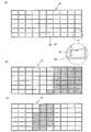
- a hand-spraying member (a) shows a preparatory stage, (b) is a plan view of a hand-spreading member when sprinkling drug A, and (c) is a plan view of a hand-spreading member. It is a plan view of the hand-spraying member, and (d) is an enlarged view of a concave portion. It is a perspective view of the hand-spreading device (drug discharge device). It is a perspective view of the hand-spreading device of FIG. 7, and is shown separately from the hand-spreading member and the divider. (A) is an exploded perspective view of the divider of FIG.
- FIG. 7 is a cross-sectional view of a temporary accommodating member.
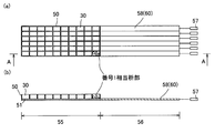
- A) is a plan view of the hand-spreading device in a state where the hand-spreading member is omitted
- (b) is a cross-sectional view taken along the line AA.
- a step of the operation when discharging the drug in the box portion of the temporary accommodating member No. 1 is shown
- FIG. (B) is a cross-sectional view taken along the line AA.
- the operation for discharging the drug in the box portion of the temporary accommodating member No. 1 and following the steps shown in FIG. 11 is shown.
- FIG. It is a plan view
- (b) is a cross-sectional view taken along the line AA.
- FIG. (B) is a cross-sectional view taken along the line AA.
- the allocation status when taking each dose is shown.
- It is a display screen view which shows an example of the display screen of the display device of the drug packaging device of FIG. Shows the allocation status when taking.
- FIG. (a) is a normal display
- (b) is a patient-specific display sorted by patient
- (c) is a confirmation display that displays before and after a specific location. ..
- the divider of the hand-spreading member adopted in another embodiment of the present invention is shown.
- FIG. (C) is a perspective view of the opening / closing mechanism portion and shows a state in which the clutch is engaged.
- FIG. 20 The relationship between the box portion of the temporary accommodating member of the divider shown in FIG. 20 and the opening / closing mechanism portion is shown, (a) shows a state in which the bottom of the box portion is closed, and (b) is a state of the box portion. Indicates that the bottom is open.
- a divider of a hand-spreading member adopted in still another embodiment of the present invention is shown, (a) is a perspective view of an opening / closing mechanism portion, and (b), (c), and (d) are an opening / closing mechanism portion. It is explanatory drawing which shows the operation of.
- a divider of a hand-spreading member adopted in still another embodiment of the present invention is shown, (a) is an exploded perspective view thereof, and (b) and (c) are explanatory views showing the operation of the opening / closing mechanism portion.
- It is a temporary accommodating member of a hand-spreading member divider adopted in still another embodiment of the present invention, (a) shows a state before inserting a closing plate into a main body, and (b) is a main body. The state where the closing plate is inserted in the part is shown.
- (A) is an enlarged view of the medication calendar and the drug accommodating portion
- (b) is a perspective view of the cleaning tool and the drug accommodating portion, showing a state before the cleaning tool is inserted into the drug accommodating portion.
- c) is a perspective view of the cleaning tool and the drug accommodating portion, and shows a state when the cleaning tool is inserted into the drug accommodating portion for cleaning.
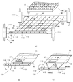
- the drug packaging device 1 of the present embodiment has an outer shape as shown in FIG.
- the drug packaging device 1 is roughly divided into a tablet supply section 2, a hand-spreading section 3, a powder supply section 5, and a drug packaging section 6.
- the hand-spreading unit 3 has a built-in hand-spreading device (drug discharge device) 10.
- the tablet supply unit 2 occupies the upper half of the drug packaging device 1.
- the tablet supply unit 2 is composed of a drug shelf 8 in which a large amount of various types of solid drugs such as capsules and tablets (hereinafter, may be simply referred to as tablets) and a large amount of tablets are stored, and a tablet transportation channel 9. Has been done.
- a large number of drug feeders (not shown) are built in the drug shelf portion 8.
- a drug cassette (not shown) is attached to each drug feeder.
- a large number of tablets are stored in the drug cassette, and the tablets are discharged one by one from the drug cassette.
- the discharged tablets are sent to the drug packaging unit 6 and packaged in sachets for each dose.
- the powder supply unit 5 and the drug packaging unit 6 occupy the lower half of the drug packaging device 1, and both are built in the parts.
- the powder powder scraped out from the powder supply unit 5 is also packaged in the same manner as tablets and the like.
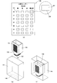
- the drug packaging device 1 is provided with a display device 11.
- the display device (guidance means) 11 is a known touch panel or the like, and has a display screen 12.
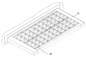
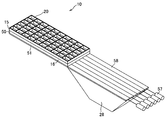
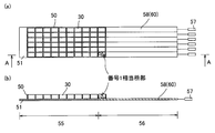
- the hand-spreading device 10 is composed of a hand-spreading member 15 and a divider 16.
- the hand-spraying member 15 is a member having a plate-like shape as a whole, and recesses 20 are arranged in a matrix.
- Each recess 20 has a bottom (not shown). The bottom can be opened and closed, and as will be described later, the bottom can be opened to transfer the drug in the recess 20 to the lower divider 16.
- each recess 20 of the hand-spreading member 15 is provided with an indicator light (instruction means guiding means) 22 so that the specific recess 20 can be illuminated and conspicuous.
- the divider 16 is a member provided with a large number of box portions 30 as in the recess 20 of the hand-spraying member 15 described above.
- the layout, that is, the number and arrangement of the box portions 30 provided in the divider 16 is the same as the layout of the recesses 20 of the hand-spreading member 15 described above, and the box portion 30 of the divider 16 is the hand-spreading member 15. It has a one-to-one correspondence with the recess 20.
- the divider 16 can open the box portion 30 at an arbitrary position in any order.
- the divider 16 is a discharging means, and can individually discharge the medicine corresponding to the arbitrary recess.
- a collecting hopper 28 is provided below the divider (discharging means) 16.
- the end portion of the collecting hopper 28 communicates with the passage leading to the drug packaging portion 6 described above.
- the divider 16 of the hand-spreading device (drug discharge device) 10 is housed in the main body portion of the drug packaging device 1.
- the hand-spraying member 15 has a drawer-like structure and enters and exits from the main body of the drug packaging device 1.
- the hand-spreading member 15 When the hand-spreading member 15 is housed in the main body of the drug packaging device 1, the hand-spreading member 15 reaches a position directly above the divider 16 as shown in FIG. 7, and all the bottoms of the recesses 20 are opened to enter the recesses 20.
- the drug is transferred to the box portion 30 of the divider 16.
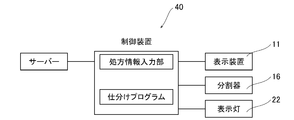
- control device 40 executes control of allocating the same drug to recesses in adjacent regions based on prescription information including information on the drug to be provided to a plurality of or one patient.
- the control device 40 functions as a recess determining means for determining the recess 20 to be sprinkled based on the type of the drug.
- the control device 40 has a function of distinguishing between a drug that can be discharged from the drug feeder and a drug that cannot be discharged. These functions are realized by a sorting program.
- the control device 40 has a known CPU, memory, and the like, and a sorting program is built in the memory. Further, the control device 40 has a prescription information input unit. An external server is connected to the control device 40. In this embodiment, prescription information is input from the server. Prescribing information includes information regarding the type and quantity of drug required. In addition, the prescription information includes other information such as quantity and timing of administration. A display device 11, a divider 16, and an indicator light 22 of a hand-spreading member 15 are connected to the output side of the control device.
- the sorting program is a program that refers to the prescription information of a plurality of patients, and if there is a common drug, puts it together to form one set.
- the prescription information includes the type of drug, the amount of the drug, the timing of administration, the method of administration, and the like.
- the drugs that need to be hand-sprayed are selected from the drugs included in the prescription information, and the information on the drugs is referred to.
- the type of drug that needs to be hand-sprayed, the dose, the timing of administration, and the like are referred to. That is, the drugs included in the prescription information include solid drugs, powdered drugs, and ointments.
- solid drugs include those that are actually stored in the tablet supply unit 2 and can be discharged from the drug feeder, and those that are not stored in the tablet supply unit 2.
- the concept of prescription information also includes what is referred to as dispensing information processed for dispensing.
- the sorting program at least, refers to information on solid drugs that are not actually stored in the tablet supply unit 2 and should be discharged using the hand-spreading device 10, and if there are common drugs, this. It is a program that puts together to make one set.
- the box portion 30 in which the set of drugs should be housed is collectively assigned to one area.
- the box portion 30 of the divider 16 has a one-to-one correspondence with the recess 20 of the hand-spreading member 15. Therefore, when the drug is allocated to the box portion 30 of the divider 16, it is substantially.
- a recess 20 (hand-spreading member 15) into which each drug is sprinkled is assigned. That is, the sorting program is a program that determines the recess 20 to be sprinkled based on the type of the drug.
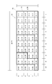
- a simulated chart (guidance means) 18 imitating the hand-spreading member 15 is displayed on the display screen 12 of the display device 11, and the assigned result is shown.
- each type of drug is color-coded, and the drugs to be sprinkled in the area are displayed as, for example, A, B, and C.
- the indicator light (guidance means) 22 of the hand-spraying member 15 is turned on to indicate the recess 20 into which the specific drug should be sprinkled.
- the drug packaging device 1 of the present embodiment can discharge necessary drugs based on prescription information input from the outside, package each dose, and discharge the necessary drugs.
- the drug packaging device 1 of the present embodiment has the following three types of patterns for packaging each dose. (1) Only the medicine discharged by the tablet supply unit 2 is packaged for each dose. (2) Only the medicine discharged by the hand-spreading device 10 is packaged for each dose. (3) The medicines discharged from the tablet supply unit 2 and the hand-spreading device 10 are combined and packaged for each dose.
- the prescription information contains a drug that is not stored in the tablet supply unit 2, it is sent from the hand-spreading device 10 to the drug packaging unit 6 and packaged.
- the drug packaging device 1 of the present embodiment distinguishes between a drug that can be discharged from the drug feeder and a drug that cannot be discharged, and the drug that is not stored in the tablet supply unit 2 and cannot be discharged from the drug feeder is a hand-spreading device 10. Is discharged from.
- a worker such as a pharmacist refers to the simulated chart 18 displayed on the display device 11 and the indicator light 22 of the hand-spraying member 15, and puts a specific drug in the recess 20 belonging to a predetermined area of the hand-spreading member 15. put in. Then, when it is time to discharge the specific drug, any one of the box portions 30 belonging to the area where the drug is grouped is opened, and the drug is discharged from the opened box portion 30.
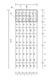
- the recesses 20 of the hand-spreading member 15 are numbered from the end.
- the drug is provided to patients a to j four times in the morning, noon, night, and before going to bed, respectively.
- the blank column is when a drug that can be supplied from the tablet supply unit 2 is taken, and the drug corresponding to the blank column is automatically supplied from the tablet supply unit 2.
- the drug is supplied from both the tablet supply unit 2 and the hand-spreading member 15, and the drug is packaged in one drug package.
- patient a takes a drug (not shown) in addition to the drug A shown in the table of FIG. 5 in the morning, and the drug is stored in the tablet supply unit 2.
- the drug is supplied from both the tablet supply section 2 and the hand-spreading member 15, and both drugs are simultaneously sent to the drug packaging section 6 for packaging.
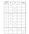
- drug A is prescribed for patients a, c, f, g, i.
- Drug B is prescribed for patients b, d, g, i.
- Drug C is prescribed for patients e, h.
- Drug D is prescribed for patient j.
- a drug package for 5 days is to be prepared, 25 packages of drug A are required, 20 packages of drug B are required, 10 packages of drug C are required, and 5 packages of drug D are required.
- the number of drugs A to be sprinkled in the recess 20 is the same for each patient or each time of administration, and if all the drugs A prescribed for each patient or each time of administration are one tablet, the numbers 1 to 25 of the recess 20 Drug A is assigned to each of the areas up to.
- the other drugs B to D are also assigned in the same manner.
- all the drugs B to D to be sprinkled in the recess 20 are one tablet for each patient or each time of administration, one drug B is assigned to each of the areas of the recess 20 from numbers 26 to 45, and the recess 20 is assigned.
- One tablet of the drug C is assigned to each of the areas Nos. 46 to 55 of 20 and one tablet of the drug D is assigned to each of the areas Nos. 56 to 60 of the recess 20.
- the area of the recess 20 from No. 1 to 25 is set as the area for drug A. Further, the area of the recess 20 from the numbers 26 to 45 is designated as the drug B area. Similarly, the region of the recess 20 from No. 46 to 55 is designated as the drug C region, and the region of the recess 20 from No. 56 to 60 is designated as the drug D region.
- a simulated chart 18 is displayed on the display screen 12 of the display device 11, and the assigned result is shown.
- the simulated chart 18 is color-coded for each area containing the drug. Further, the type of the drug is displayed in the frame corresponding to the recess 20. In this way, a unified mark is displayed in the frame of the recess 20 in which the same drug should be placed in the simulated chart 18.
- a worker such as a pharmacist refers to the simulated chart 18 displayed on the display device 11 and the indicator light 22 of the hand-spreading member 15 in the recess 20 belonging to a predetermined area of the hand-spreading member 15. , Put a specific drug.
- the same number of drugs may be collected or the drugs may be collected in the order of the patients, and the numbers 1 to 25 of the recess 20 are collected. Assign to drug A.
- the other agents B to D are similarly assigned.
- the indicator light 22 in the area for the drug A of the hand-spraying member 15 is first turned on.
- an end switch (not shown) is pressed.
- the lighting area of the hand-spraying member 15 changes, and as shown in FIG. 6C, the indicator light of the drug B area of the hand-spreading member 15 lights up.
- the lighting area of the hand-spraying member 15 changes.
- the camera, sensor, and weight may automatically detect the end of sprinkling and change the lighting area.
- the predetermined end switch is pressed.
- the hand-spraying member 15 is housed in the main body of the drug packaging device 1, and the hand-spreading member 15 reaches a position directly above the divider 16 and opens all the bottoms of the recesses 20 to open the drug in the recesses 20. Is transferred to the box portion 30 of the divider 16.
- a structure may be adopted in which the hand-spraying member 15 is manually pushed into the main body to accommodate the member 15.
- any one of the box portions 30 of the divider 16 corresponding to the area where the drug is collected is opened. Then, the drug is discharged.
- the basin 30 corresponding to any of the medicine A regions Nos. 1 to 25 of the recess 20 is opened to discharge the medicine A.
- the basin 30 corresponding to any of the medicine C regions of the recesses 20 from Nos. 46 to 55 is opened and the medicine C is discharged.
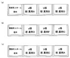
- the medicines can be discharged in an arbitrary order, and sorting suitable for delivering the medicines to the above-mentioned nursing care facility can be performed. That is, the medicines taken by each patient in the morning are grouped together to form a morning set, the drugs taken by each patient in the daytime are grouped together to form a daytime set, and the drugs taken by each patient at night are grouped together to form a nighttime set. It is possible to make a group of medicines to be taken before the patient goes to bed, make a group for before going to bed, and bring it to a nursing facility or the like. If necessary, set the drug packaging on the medication calendar and bring it to a nursing care facility.
- the procedure is as follows.
- the drugs to be taken in the morning are: patient a is drug A, patient b and patient c are drugs discharged from the tablet supply unit 2, patient d is drug B, patient e is drug C, and patient f is.
- the drug A and the patient g are the drug B, the patient h is the drug discharged from the tablet supply unit 2, the patient i is the drug A, and the patient j is the drug discharged from the tablet supply unit 2.
- the medicines taken by each patient in the morning are grouped together to form a morning set, the medicines are discharged in the above-mentioned order. Specifically, first, the basin 30 corresponding to the recess 20 of No. 1 belonging to the drug A region is opened to discharge the drug A for the patient a. Subsequently, the drug for patient b and the drug for patient c are sequentially discharged from the tablet supply unit 2. Subsequently, the basin 30 corresponding to the recess 20 of the number 26 belonging to the drug B region is opened to discharge the drug B for the patient d. Subsequently, the box portion 30 corresponding to the recess 20 of the number 46 belonging to the drug C region is opened, and the drug C for the patient e is discharged.
- the basin 30 corresponding to the recess 20 of No. 2 belonging to the drug A region is opened, and the drug A for the patient f is discharged.
- the basin 30 corresponding to the recess 20 of the number 27 belonging to the drug B region is opened, and the drug B for the patient g is discharged.
- the drug for patient h is discharged from the tablet supply unit 2.
- the basin 30 corresponding to the recess 20 of No. 3 belonging to the drug A region is opened, and the drug A for patient i is discharged.
- the drug for patient j is discharged from the tablet supply unit 2. In this way, the medicines that each patient takes in the morning can be sequentially discharged to form a morning assembly.
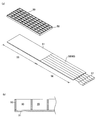
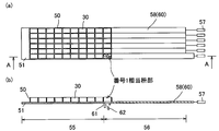
- the hand-spreading device 10 of the present embodiment includes a hand-spreading member 15 and a divider 16.
- the divider 16 has a temporary accommodating member 50 and a bottom constituent member 51 as shown in FIGS. 8 and 9 (a).
- the temporary accommodating member 50 has a plurality of box portions 30, and the arrangement of the box portions 30 has a one-to-one correspondence with that of the recess 20 of the hand-spreading member 15.
- the box portion 30 of the temporary housing member 50 has no bottom, and the box portion 30 itself is always in an open state. However, there is a bottom component 51 on the bottom side of the temporary housing member 50, and the bottom side of the box portion 30 is closed by the bottom component 51.
- the bottom component 51 is composed of a fully closed area 55 and an openable area 56.
- the fully closed area 55 is composed of a single plate and has substantially no opening.
- the openable area 56 is configured by arranging six moving floor members 58 in a plane.
- the moving floor member 58 includes a flat strip-shaped member 60 having a narrow width.
- the moving floor member 58 can be individually translated by a drive source 57 such as a solenoid.
- a drop opening 61 is formed at the boundary between the fully closed region 55 and the openable region 56.
- the entire closed area 55 has an area sufficient to cover the entire bottom of the temporary accommodating member 50.
- the openable region 56 has an area sufficient to cover the entire bottom surface of the temporary accommodating member 50 in a state where the six strip-shaped members 60 are combined in a rectangular shape.
- the temporary accommodating member 50 can be translated and stopped at an arbitrary position by a drive source (not shown). Also in the hand-spraying device 10 of the present embodiment, when the hand-spreading member 15 is housed in the main body of the drug packaging device 1, the hand-spreading member 15 reaches a position directly above the divider 16 and forms the bottom of the recess 20. All are opened and the medicine in the recess 20 is transferred to the box portion 30 of the temporary storage member 50.
- the hand-spreading device (drug discharge device) 10 of the present embodiment has a discharge means for temporarily opening the bottom of the box portion 30 at an arbitrary position to discharge the drug from the box portion 30.
- the discharging means is composed of the temporary accommodating member 50 and the bottom constituent member 51 described above. The discharge procedure will be described below. For example, when opening the box portion 30 corresponding to the recess 20 of No. 1, the temporary accommodating member 50 is moved by one box as shown in FIG. Subsequently, as shown in FIG. 12, the moving floor member 58 in the first row is moved by one square to form a drop opening 61 for one square between the fully closed region 55 and the openable region 56. As a result, the bottom of the box portion 30 corresponding to the concave portion of No. 1 is released, and the drug 62 is released from the concave portion of No. 1.
- the box portion 30 corresponding to the number 28 is in the fifth row from the right side and in the fourth column from the bottom.
- the temporary accommodating member 50 is moved by 5 boxes as shown in FIG.
- the temporary accommodating member 50 greatly protrudes from the entire closed area 55, but the openable area 56 has an area sufficient to cover the entire bottom portion of the temporary accommodating member 50, so that the bottom of each box portion 30 is closed. The state is maintained. Subsequently, as shown in FIG.
- the moving floor member 58 in the fourth row from the bottom is moved by one square, and is between the fully closed area 55 and the openable region 56, and one square in the fourth row portion.
- a drop opening 61 for the minute is formed.
- the bottom of the box portion 30 corresponding to the recess 20 of the number 28 is released, and the drug 62 is discharged from the recess 20 of the number 28.
- a plurality of moving floor members 58 are provided, and each moving floor member 58 is moved independently to create only one drop opening 61.
- the opening / closing member is provided at a specific position. It may be provided and the opening / closing member may be opened / closed by a motor or a solenoid.
- a motor or a solenoid For example, for example, six openings are arranged in a row direction at the boundary between the fully closed area 55 and the openable area 56, and each opening is provided with an opening / closing member such as a hinge that can be opened / closed. It may be opened and closed.
- the number of chemicals to be put into each recess 20 of the hand-spraying member 15 is arbitrary and may be one or a plurality.
- the drug packaging section 6 is provided with a plurality of drugs by inserting the drug into the recess 20 one by one and discharging the drug from the basin 30 a plurality of times. May be supplied to.
- the drug may be transferred from the recesses 20 in which different drugs are housed to the plurality of box portions 30, and the drug may be supplied from the plurality of box portions 30 to one drug package. In addition, it does not deny that the drug for one dose is divided into multiple drug packages and stored.
- the hand-spraying device (drug discharge device) 10 of the embodiment described above discharges the drug sprinkled into the recess 20 of the hand-spreading member 15 via the divider 16 of the hand-spreading member 15.
- the recesses 20 may be individually opened and closed to discharge the drug directly from the hand-spraying member 15.
- the recess 20 of the hand-spreading member 15 has a structure in which there is no bottom and the bottom is open. Then, the bottom constituent member 51 as described above is arranged below the hand-spraying member 15, so that the hand-spraying member 15 and the bottom constituent member 51 can be moved relative to each other, and at least one of the hand-spreading member 15 and the bottom constituent member 51. To move the specific recess 20 to a position where the drop opening 61 of the bottom component 51 is formed.
- the above-mentioned usage pattern is an example in which one tablet of the drug should be sprinkled into the recess 20 of the hand-spreading member 15.
- drug packages taken at the same time can form a continuous bandage.
- Other usage patterns include the following usage examples.
- the medicine to be supplied from the hand-spreading device (drug discharge device) 10 and the medicine to be taken at one time is sprinkled into one recess 20. Further, in any case, those having the same type and number of agents are assigned to the recesses in the adjacent regions.
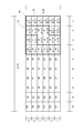
- patient a may take one tablet of drug A in the morning, one tablet of drug B in the daytime, and two tablets of drug A in the evening.
- patient b may take 1 tablet of drug A in the morning, 1 tablet of drug B in the daytime, and 2 tablets of drug A in the evening.
- a drug package for 4 days is to be made, 8 drug packages containing 1 tablet of drug A are required, 8 drug packages containing 2 tablets of drug A are required, and 1 drug B is required.
- Eight lock-wrapped drug packages are required. In this case, as shown in FIG. 17, the recesses 20 Nos.
- Subsequent recesses 20 numbers 9 to 16 are allocated as areas for containing two drug A tablets at a time.
- Subsequent recesses 20 numbers 17 to 24 are allocated as areas for inserting drug B one tablet at a time.
- patient a may take 1 tablet of drug A and 1 tablet of drug B in the morning, 1 tablet of drug B in the daytime, and 2 tablets of drug A in the evening.
- patient b may take 2 tablets of drug A in the morning, 1 tablet of drug B in the daytime, 1 tablet of drug A and 1 tablet of drug B in the evening.
- you want to make a drug package for 4 days you need 1 tablet for drug A, 1 tablet for drug B, 8 drug packages packaged in one bag, and 2 drug packages for drug A. Eight packages are required, and eight drug packages containing one tablet of drug B are required. In this case, as shown in FIG.
- numbers 1 to 8 of the recess 20 are allocated as an area for containing one drug A and one drug B.
- Subsequent recesses 20 numbers 9 to 16 are allocated as areas for containing two drug A tablets at a time.
- Subsequent recesses 20 numbers 17 to 24 are allocated as areas for inserting agent B one tablet at a time.
- the same drug is assigned to the recesses in the adjacent regions in a state where the drawings are right-justified and along the columns.
- the invention is not limited to this configuration. For example, they may be arranged left-justified or collected along a row.
- the recesses 20 are arranged in 10 rows and 6 columns as shown in FIG. 4, but the number of rows and columns of the hand-spreading member 15 is arbitrary.
- the recommended number of columns is 7. For example, if the 1st to 7th days of the patient a are the 1st to 7th columns and the 1st to 4th rows are the morning, noon, night, and before sleep, it is easy to sprinkle. Further, if the 5th line is left and the 6th to 9th lines are continued as the morning, noon, night, and before sleep when the patient b is taken, it is easy to sprinkle while avoiding the mistake of handing between patients.
- the drug packaging device 1 of the embodiment described above includes a tablet supply section 2, a hand-spreading section 3, a powder supply section 5, and a drug packaging section 6, and is a hand-spreading device (drug) characteristic of the hand-spreading section 3.
- Discharge device 10 is adopted. It is desirable that the drug packaging device includes the tablet supply unit 2 and the powder supply unit 5 as in the above-described embodiment, but the drug packaging device that does not have the tablet supply unit 2 and the like is provided with the hand-spreading device of the present invention. (Drug discharge device) 10 may be adopted.
- the present invention is also applied to a device that discharges all the drugs contained in the prescription information (including the prescription information obtained by processing the prescription information for dispensing) input to the drug packaging device from the drug discharge device (hand-spreading member). be able to.
- the inspection device may be built in the drug packaging device 1 or may be a separate device.
- a bandage in which a plurality of patients take a continuous drug package in the morning and a bandage in which a plurality of patients take a drug package in the daytime are continuous. It is possible to make a bandage, a continuous bandage with a drug package taken by a plurality of patients at night, and a bandage with a continuous drug package taken by a plurality of patients before going to bed.
- the drug packaging discharged from the drug packaging device 1 is discharged by connecting the drug packagings to be taken by the patient a, the patient b, the patient c ..., the patient i, and the patient j in the morning, and then these patients are discharged.
- the drug packaging taken in the daytime is connected and discharged.
- the inspection device of the present embodiment has a camera and photographs the drug packages discharged from the drug packaging device 1 in the order in which they are discharged, and identifies the packaged drug from the stamp of the drug, the shape, and the like.
- the captured image is image-processed, and a drug having a similar shape, size, color, etc. is searched for. Then, the drug in the drug package is presumed to be the searched drug.
- the inspection device of the present embodiment has a sorting function for rearranging images, and can display the drug packaging for each patient as shown in FIG. 19B.
- FIG. 19B when patient a is selected, only the drug taken by the patient a is displayed in a state in which the date of administration and the time of administration (morning, noon, night) can be known. If the prescription is for two weeks, the drug packaging for two weeks will be displayed.
- the drug packages can be displayed in the order in which they are discharged from the drug packaging device 1. Furthermore, it is possible to specify a specific drug package for a specific patient and check the contents of the drug package discharged before and after the drug package.
- the inspection device of the present embodiment can display the drug package discharged before and after the drug package containing the drug scheduled to be taken by patient a on October 7. Therefore, it is possible to investigate the reason why the drug was not correctly packaged. Further, the screen may be automatically switched to the state shown in FIG. 19C when there is a problem that the medicines in the medicine packaging are different or the number is different depending on the judgment of the inspection device.
- a display calling attention appears on the monitor or the like.
- a audible warning may be given.
- Drugs of similar shape and size may be difficult to determine by image processing, and pharmacists should perform more careful visual confirmation. Therefore, for example, it is desirable that a display calling attention is displayed on any of the screens of FIG.
- the divider 63 described below has a temporary accommodating member 64.
- the temporary accommodating member 64 has the box portions 30 arranged in a matrix, similarly to the divider 16 described above.
- the box portion 30 has a one-to-one correspondence with that of the recess 20 of the hand-spreading member 15.
- an opening / closing member 65 is provided at the bottom of each box portion 30.
- the opening / closing member 65 has a plate shape, and an intermediate portion thereof is pivotally supported by a part of the box portion 30.
- the opening / closing member 65 has a plate shape and swings around the shaft support 66.
- One side of the opening / closing member 65 functions as a lid member 67 and the other side functions as a force point portion 68 with the shaft support portion 66 as a boundary.
- the lid member 67 of the opening / closing member 65 is located below the opening at the bottom of the box portion 30.
- the force point portion 68 of the opening / closing member 65 is located at a position away from the box portion 30.
- the opening / closing member 65 is urged by the urging means 70 in a direction in which the lid member 67 closes the bottom of the box portion 30.
- the divider 63 of the present embodiment includes a drive mechanism 71, an operating member 72, and a clutch mechanism 73.
- the acting member 72 urges the opening / closing member 65 to swing the opening / closing member 65.
- the drive mechanism 71 drives the working member 72.
- the clutch mechanism 73 is located between the drive mechanism 71 and the working member 72, and intermittently connects the two.
- the drive mechanism 71 is obtained by arranging racks 77a to 77 extending in the horizontal direction in the drawing in six rows in the vertical direction. Pinions 79 driven by the motor 76 are engaged with the racks 77a to 77, and the racks 77a to f move linearly by driving the motor 76.
- the acting member 72 is a cam. Gear teeth 74 are formed on a part of the working member 72.
- the clutch mechanism 73 has connecting rods 73a to j and a solenoid 75.
- the six working members 72 are connected by connecting rods 73a to j.
- the acting member 72 is rotatable with respect to the connecting rods 73a to 73j.
- the working member 72 is axially integral with the connecting rods 73a to j.
- a solenoid 75 is attached to each of the connecting rods 73a to 73, and by driving the solenoid 75, the connecting rods 73a to jj individually move linearly.
- the connecting rods 73a to 73j extend in the vertical direction of the drawing and are arranged in 10 rows in the horizontal direction.
- Each working member 72 is always beside the racks 77a to 77 as shown in FIG. 20B, and the gear teeth 74 of each working member 72 are not engaged with the racks 77a to f. ..
- the solenoid 75 located on the far right of the drawing in FIG. 20 (a) is energized to move the connecting rod 73a, all the working members 72 attached to the connecting rod 73a as shown in FIG. 20 (c).
- Gear teeth 74 engage with racks 77a-f.
- the basin portion 30 at an arbitrary position can be opened in any order even for the divider 63 of the embodiment.
- the divider 63 it is possible to individually discharge the medicine corresponding to the arbitrary recess 20. That is, the connecting rods 73a to j in the parallel column to which the box portion 30 to be opened belongs are driven by the solenoid 75, and all the working members 72 in the parallel column to which the box portion 30 to be opened belongs are engaged with the racks 77a to f. .. Then, only the rows of racks 77a to 77 to which the box portion 30 to be opened belongs are driven.
- the racks 77a to 77 were driven by a motor, and the connecting rods 73a to j were driven by a solenoid.
- the drive source for driving the racks 77a to f and the connecting rods 73a to j is not limited, and the racks 77a to ff may be driven by a solenoid. Further, the connecting rods 73a to 73j may be driven by a motor.
- the connecting rods 73a to jj are driven by a plurality of power sources, but the number of power sources can be reduced by using a one-way clutch or the like.
- all the connecting rods 73a to jj are driven by one stepping motor 89.
- the divider 80 has a rotating shaft 81, and drive-side members 82 are attached to the rotating shaft 81 in a number corresponding to connecting rods 73a to j.
- the rotation shaft 81 is rotated by a stepping motor 89.
- the drive side member 82 is a disk provided with a stepped engaging portion 84 in a part thereof.
- One side of the stepped engaging portion 84 has an acute angle with respect to the circumference, and the other side is gently continuous with respect to the circumference.
- the drive-side member 82 is fixed to the rotating shaft 81 in a state where the position of the stepped engaging portion 84 is slightly shifted.
- a driven side member 83 is attached to each of the connecting rods 73a to 73j.
- the driven side member 83 is a member provided with an engaging portion 85 at the tip thereof.
- the engaging portion 85 has a hook shape bent at an acute angle.
- the engaging portion 85 of the driven side member 83 is in contact with the driving side member 82.
- FIG. 22B when the drive side member 82 is rotated in the direction of the arrow of the broken line, the stepped engaging portion 84 of the drive side member 82 does not engage with the engaging portion 85.
- the stepped engaging portion 84 of the drive side member 82 becomes the engaging portion as shown in FIG.
- the driven side member 83 in the parallel column to which the box portion 30 to be opened belongs is engaged with the drive side member 82, and the box portion 30 to be opened by moving the specific connecting rods 73a to j belongs. All working members 72 in the column are engaged with the racks 77a-f. Specifically, as shown in FIG. 22B, the drive-side member 82 is rotated in the direction of the arrow of the broken line, and the engaging portion 85 connected to the specific connecting rods 73a to 73 is connected to the corresponding drive-side member. It is stopped at a position where it fits into the stepped engaging portion 84 of 82.
- the drive side member 82 is fixed to the rotating shaft 81 in a state where the position of the stepped engaging portion 84 is slightly shifted, it fits into the stepped engaging portion 84 of the drive side member 82.
- the engaging portion 85 is limited to those connected to the specific connecting rods 73a to 73j.
- the divider 87 shown in FIG. 23 is composed of a temporary accommodating member 50 and an opening forming device 90.
- the temporary accommodating member 50 has the same structure as that of the first embodiment, the basin portion 30 has no bottom, and the basin portion 30 itself is always in an open state.
- the opening forming device 90 includes an opening specifying portion 91, an opening / closing portion 92, and an opening / closing mechanism portion 94.
- the opening specifying portion 91 has six drawer-side members 93, six take-up-side members 95, and six belts 96, respectively.
- the drawer side member 93 has a plurality of drawer pulleys 121 arranged in series on a support shaft (not shown).
- the drawer pulley 121 has a built-in motor.
- the take-up side member 95 has a plurality of take-up pulleys 122 arranged in series on a support shaft (not shown).
- a mainspring 122 is built in the take-up pulley 122, and is always urged to rotate toward the take-up side.
- a belt 96 is wound around the take-up pulley 122, and one end of the belt 96 is connected to the drawer pulley 121. Therefore, when the drawer pulley 121 is rotated, the belt 96 wound around the take-up pulley 122 is unwound.
- Each belt 96 is provided with an opening 97 in one place. Therefore, the position of the opening 97 changes according to the rotation speed of the drawer pulley 121.
- the opening / closing part 92 has 11 swing doors 98 corresponding to the columns of the box parts 30 of the temporary housing member 50.
- An operation piece 110 projects from each swing door 98.
- the opening / closing mechanism unit 94 has a guide member 111 and an elevating member 112 regulated so as to be movable only in the vertical direction by the guide member 111.
- the elevating member 112 has an elongated hole 113, and the operating piece 110 of the swing door 98 is engaged with the elongated hole 113.
- a rotating plate 115 rotated by a motor (not shown) is provided, and the engaging piece 116 provided on the rotating plate 115 is also engaged with the elongated hole 113 of the elevating member 112. The rotating plate 115 is always stopped with the engaging piece 116 in the upper position.
- the elevating member 112 is in the upper position, and all the opening / closing portions 92 are in positions where the bottom of the box portion 30 can be closed.
- the elevating member 112 moves to the lower side, and all the opening / closing portions 92 are released.
- one of the drawer pulleys 121 is driven to move the opening 97 of the belt 96 to the lower part of the box portion 30 to be opened.
- the rotating plate 115 is rotated to open all the opening / closing portions 92.
- the box portion 30 in which the opening 97 of the belt 96 is moved to the lower portion is substantially opened, and the drug in the box portion 30 drops.
- the structure of the divider is arbitrary, and one having an opening / closing door 123 at the lower part of each of the basin parts 30 may be used as in the known temporary housing member 117 shown in FIG. 24.
- the temporary accommodating member 117 having this structure is periodically removed from the drug packaging device and reattached to the drug packaging device for cleaning.
- the temporary accommodating member 117 having the opening / closing door 123 at the lower part of each box portion 30 must be held down so that the opening / closing door 123 does not open when the opening / closing door 123 is attached to the drug packaging device. It takes skill.
- the temporary accommodating member 117 of this aspect solves this problem.
- the temporary accommodating member 117 of this embodiment is provided with a closing plate insertion guide 118 on the bottom surface of the main body portion, and the closing plate 120 is mounted on the bottom surface of the main body portion.
- the closing plate 120 is inserted along the closing plate insertion guide 118, and the opening / closing door 123 at the lower part of each box portion 30 can be pressed to bring the closing plate 120 into the closed state.
- the temporary accommodating member 117 of this embodiment is attached to the drug packaging device with the closing plate 120 attached.
- the temporary accommodating member 117 moves to the collecting hopper side after the drug is charged into each of the basin portions 30 from the hand-spreading member 102.
- the sorter device 130 has a plurality of guide portions 132 and 133. In the present embodiment, there are two guide portions 132 and 133, but the number of guide portions 132 and 133 is arbitrary. Further, each guide portion 132, 133 is provided with a package holding means (not shown). The package holding means holds a part of the package by sandwiching it.
- the sorter device 130 is installed in the vicinity of the drug packaging discharge port 131 of the drug packaging device, and is moved up and down by an elevating means (not shown).
- the first guide portion 132 on the lower side is moved to the position of the drug packaging discharge port 131 as shown in FIG. 25 (b).
- the packaging band 138 for patient a hangs down in contact with the first guide portion 132.
- the packaging band 138 is cut in the drug packaging device, and the end portion of the packaging band 138 is held by the first guide portion 132 by the package holding means.
- the sorter device 130 is lowered, and the second guide portion 133 on the upper side is moved to the position of the drug packaging discharge port 131. Then, when the drug package for patient b is discharged from the drug package discharge port 131, the package band 139 for patient b hangs down in contact with the second guide portion 133, and the package band 139 is cut. Then, the end portion of the packaging band 139 is held by the second guide portion 133 by the packaging body holding means.
- the subsequent packaging band for patient c is discharged from the drug packaging discharge port 131 as it is.
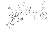
- the printer 136 is located on the upstream side of the hopper 135, and the heater roller 137 is located on the downstream side of the hopper 135.
- the printer 136 prints the necessary prints on the wrapping paper 143, and then the hopper 135 supplies the drug to the wrapping paper 143. In this state, the wrapping paper 143 moves to the downstream side and is molded into individual bags by the heater roller 137.
- the last drug for patient a is discharged from the hopper 135. Is supplied to the wrapping paper 143, and then the first drug for the patient b is supplied to the wrapping paper 143, so that the drug is continuously supplied to the wrapping paper 143 and the wrapping paper 143 is not wasted.
- the wrapping paper 143 is wasted. That is, when the drug for patient a is supplied to the wrapping paper 143, the wrapping paper 143 is moved to the position of the heater roller 137 and molded into a bag shape, but when the wrapping paper 143 is moved to the position of the heater roller 137. Then, the subsequent wrapping paper 143 is pulled to move to the lower part of the hopper 135 or the position of the printer 136. However, the drug is not supplied to the wrapping paper 143 that has reached the hopper 135. None is printed on the wrapping paper 143 that has reached the position of the printer 136. Therefore, the wrapping paper 143 in the region from the printer 136 to the heater roller 137 is wasted.
- the drug packaging at or near the end is stopped, and the next drug packaging is stopped for a certain period of time. Wait for the prescription to be sent to the drug packaging device. If the next prescription to be processed is sent within a certain period of time, drug packaging will be resumed. For example, if the prescription for patient a should be followed by the prescription for patient b, the remaining drug packaging for patient a is resumed, followed by the drug for patient b. Carry out packaging. If the next prescription to be processed is not sent within a certain period of time, the remaining drug packaging for patient a is restarted to complete the drug packaging for patient a.
- the above-mentioned medication calendar is provided with a drug accommodating unit 141 for accommodating a drug on the calendar.
- a drug accommodating unit 141 for accommodating a drug on the calendar.
- 141 drug storage units are arranged below each date.
- Each of the four drug storage units 141 corresponds to the timing (usage) of administration, and is indicated as, for example, "morning", "daytime”, “night”, and "before going to bed”.
- the medicine corresponding to the timing of administration is stored in the medicine storage unit 141 of the medication calendar (medicine calendar) 140.
- the timing of taking the drug arrives, the drug is taken out from the corresponding drug accommodating section 141 and taken.
- the drug accommodating portion 141 is pocket-shaped. Therefore, dust 145 may collect at the bottom of the drug accommodating portion 141. Further, the bottom of the drug accommodating portion 141 is often angular, and it may be difficult to remove dust in the corner portion. As a measure for solving this problem, it is recommended to use the cleaning tool 150 as shown in FIG. 27 (b).
- the cleaning tool 150 is an attachment attached to the tip of a vacuum cleaner.
- the cleaning tool 150 has a rectangular parallelepiped appearance.
- the front wall and the back wall of the cleaning tool 150 are wide, and the side wall is narrow.
- the inside of the cleaning tool 150 is hollow, and there is an opening 152 at a corner portion on the tip side.
- a brush 151 is attached to the front wall, the back wall, and the bottom wall of the cleaning tool 150.
- the brush 151 is planar and thin, and is attached to the main body of the cleaning tool 150 by an adhesive means (not shown).
- the cleaning tool 150 is attached to a vacuum cleaner (not shown). Then, as shown in FIG. 27 (c), the cleaning tool 150 is inserted into the drug accommodating section 141 of the medication calendar 140, and the cleaning tool 150 is moved in the drug accommodating section 141 in the loading / unloading direction. As a result, the inner surface of the drug accommodating portion 141 is rubbed with the brush 151, and dust and dirt adhering to the inner surface of the drug accommodating portion 141 are removed. Further, the removed dust and dirt are sucked through the opening 152. In particular, in the present embodiment, since the opening 152 is provided at the corner portion on the tip end side of the cleaning tool 150, it is possible to clean the corner portion of the drug accommodating portion 141 where dust is likely to collect. It is desirable that the brush 151 is replaceable.
Abstract
The present invention addresses the problem of providing a drug discharge device that can reduce the complexity involved in dispensing a drug into a manual dispensing device. This drug discharge device comprises: a manual dispensing member 15 provided with a plurality of recesses 20 into which solid drugs are dispensed; a discharge means for discharging the drugs that have been dispensed into the recesses 20, so as to be discharged downstream either directly or with another member being interposed; and a control device for controlling the discharge means. The drug discharge device wherein: the discharge means is capable of individually discharging drugs corresponding to any of the recesses 20; and the control device, on the basis of prescription information including information on the drugs to be provided to one or more patients, allocates the same drug to the recesses 20 in a proximate region, with the discharge means discharging the drugs in a prescribed order.
Description
本発明は、手撒き装置と称されるものであり、固形状の薬剤を下流側の包装装置等に排出する薬剤排出装置に関するものである。また本発明は、薬剤排出装置の制御方法に関するものである。
The present invention is referred to as a hand-spreading device, and relates to a drug discharging device that discharges a solid drug to a packaging device or the like on the downstream side. The present invention also relates to a method for controlling a drug discharge device.
錠剤やカプセル等の固形状の薬剤を一包ずつ包装する薬剤包装装置が知られている(特許文献1)。一般に薬剤包装装置は、複数の薬剤フィーダを備えた薬剤貯留部と薬剤を包装する薬剤包装部とを備えている。そして薬剤フィーダに錠剤等が充填された薬剤カセットが取り付けられている。
上記した薬剤包装装置では、薬剤フィーダによって薬剤カセットに貯留された錠剤を一個ずつ取り出し、当該錠剤を薬剤包装部に送り、包装紙等によって一回服用分ずつ包装する。 A drug packaging device for packaging solid drugs such as tablets and capsules one by one is known (Patent Document 1). Generally, the drug packaging device includes a drug storage unit provided with a plurality of drug feeders and a drug packaging unit for packaging the drug. A drug cassette filled with tablets or the like is attached to the drug feeder.
In the above-mentioned drug packaging device, the tablets stored in the drug cassette are taken out one by one by the drug feeder, the tablets are sent to the drug packaging section, and the tablets are packaged one by one with wrapping paper or the like.
また薬剤包装装置には、下記の特許文献2に開示された様な、当業者の間で「手撒き」と称される機能を備えたものがある。ここで「手撒き」とは、薬剤フィーダを介さず、手指やロボット等によって所定の錠剤等を一包分ずつ投入し、薬剤包装部に送って包装するものである。
In addition, some drug packaging devices have a function called "hand-spreading" among those skilled in the art, as disclosed in Patent Document 2 below. Here, "hand-spreading" means that a predetermined tablet or the like is injected one by one by a finger or a robot without using a drug feeder and sent to a drug packaging section for packaging.
図28は、特許文献2に開示された薬剤包装装置で採用された手撒き装置の斜視図である。
特許文献2に開示された手撒き装置100は、手撒き部材102及び分割枡ユニット103を備えている。特許文献2に開示された薬剤包装装置では、分割枡ユニット103は図示しない本体内に配されている。また手撒き部材102は、図示しない本体に対して手動でスライドできる様に取付けられている。
手撒き部材102は、凹部が縦横の行列状に設けられた板状体である。
また分割枡ユニット103には、枡部が縦横の行列状に設けられている。分割枡ユニット103の枡部の配列は、手撒き部材102の凹部の配列に対応している。
手撒き部材102は、引き出し枠101に着脱自在に装着される。
特許文献2に開示された薬剤包装装置では、手撒き部材102を引き出し枠101ごと本体から引き出す。
そして当該手撒き部材102の凹部に手指をもって錠剤を投入する。
その後、手撒き部材102を薬剤包装装置の図示しない本体内に挿入する。 FIG. 28 is a perspective view of the hand-spreading device adopted in the drug packaging device disclosed inPatent Document 2.
The hand-spraying device 100 disclosed in Patent Document 2 includes a hand-spreading member 102 and a split box unit 103. In the drug packaging device disclosed in Patent Document 2, the split box unit 103 is arranged in a main body (not shown). Further, the hand-spraying member 102 is attached so that it can be manually slid with respect to a main body (not shown).
The hand-sprayingmember 102 is a plate-like body in which recesses are provided in a vertical and horizontal matrix.
Further, thesplit box unit 103 is provided with box portions in a vertical and horizontal matrix. The arrangement of the box portions of the split box unit 103 corresponds to the arrangement of the recesses of the hand-spreading member 102.
The hand-sprayingmember 102 is detachably attached to the drawer frame 101.
In the drug packaging device disclosed inPatent Document 2, the hand-spraying member 102 is pulled out from the main body together with the drawer frame 101.
Then, the tablet is put into the recess of the hand-spreadingmember 102 with a finger.
After that, the hand-spreadingmember 102 is inserted into the main body of the drug packaging device (not shown).
特許文献2に開示された手撒き装置100は、手撒き部材102及び分割枡ユニット103を備えている。特許文献2に開示された薬剤包装装置では、分割枡ユニット103は図示しない本体内に配されている。また手撒き部材102は、図示しない本体に対して手動でスライドできる様に取付けられている。
手撒き部材102は、凹部が縦横の行列状に設けられた板状体である。
また分割枡ユニット103には、枡部が縦横の行列状に設けられている。分割枡ユニット103の枡部の配列は、手撒き部材102の凹部の配列に対応している。
手撒き部材102は、引き出し枠101に着脱自在に装着される。
特許文献2に開示された薬剤包装装置では、手撒き部材102を引き出し枠101ごと本体から引き出す。
そして当該手撒き部材102の凹部に手指をもって錠剤を投入する。
その後、手撒き部材102を薬剤包装装置の図示しない本体内に挿入する。 FIG. 28 is a perspective view of the hand-spreading device adopted in the drug packaging device disclosed in
The hand-
The hand-spraying
Further, the
The hand-spraying
In the drug packaging device disclosed in
Then, the tablet is put into the recess of the hand-spreading
After that, the hand-spreading
手撒き部材102は、本体内に挿入された状態においては分割枡ユニット103の上部に位置する。そして手撒き部材102の各凹部の底部が開き、各凹部内の錠剤が分割枡ユニット103の枡部に投入される。
その後、分割枡ユニット103の底部が順次開かれ、下部に設けられた薬剤包装部105に錠剤が一包分ずつ送られて、包装される。 The hand-sprayingmember 102 is located above the split box unit 103 when it is inserted into the main body. Then, the bottom of each recess of the hand-spreading member 102 is opened, and the tablets in each recess are put into the box of the split box unit 103.
After that, the bottom of thesplit box unit 103 is sequentially opened, and the tablets are sent one by one to the drug packaging unit 105 provided at the bottom and packaged.
その後、分割枡ユニット103の底部が順次開かれ、下部に設けられた薬剤包装部105に錠剤が一包分ずつ送られて、包装される。 The hand-spraying
After that, the bottom of the
従来技術の手撒き装置では、分割枡ユニット103の枡部を開く順番が決まっており、分割枡ユニット103の枡部は、端部から一個ずつ順番に開かれてゆく。
In the conventional hand-spreading device, the order in which the basin portions of the split basin unit 103 are opened is determined, and the basin portions of the split basin unit 103 are opened one by one from the end.
例えば一人の患者(例えば患者a)の処方が、朝に薬剤Aを服用し、昼に薬剤Bを服用し、夜に薬剤Cを服用するものであるならば、薬剤師は、手撒き部材102の1行1列目の凹部に朝用の薬剤Aを入れ、続く1行2列目の凹部に昼用の薬剤Bを入れ、続く1行列目の凹部に夜用の薬剤Cを入れ、以後、この作業を繰り返す。
手撒き装置から、薬剤が投入順に下流側の包装部に排出され、一服用分ずつ順次包装されてゆく。
その結果、薬剤排出装置からは、患者aが服用する薬剤包装が、朝、昼、夜等の服用時期順に排出されていく。
従来技術の手撒き装置100は、上記した様に、薬剤を包装するべき順番に、手撒き部材102の凹部に入れる必要があり、慎重を要する作業であった。そのため、薬剤師の精神的負担が大であった。 For example, if the prescription of one patient (eg, patient a) is to take drug A in the morning, drug B in the daytime, and drug C in the evening, the pharmacist will take the hand-spreadingmember 102. Put the morning medicine A in the recesses in the 1st row and 1st column, put the daytime medicine B in the recesses in the 1st row and 2nd column, put the night medicine C in the recesses in the 1st row, and then put the medicine C for the night. Repeat this process.
From the hand-spreading device, the drugs are discharged to the packaging section on the downstream side in the order of injection, and each dose is sequentially packaged.
As a result, the drug package to be taken by the patient a is discharged from the drug discharge device in the order of the time of administration such as morning, noon, and night.
As described above, the hand-sprayingdevice 100 of the prior art needs to be put into the recesses of the hand-spreading member 102 in the order in which the chemicals should be packaged, which is a careful work. Therefore, the mental burden on the pharmacist was great.
手撒き装置から、薬剤が投入順に下流側の包装部に排出され、一服用分ずつ順次包装されてゆく。
その結果、薬剤排出装置からは、患者aが服用する薬剤包装が、朝、昼、夜等の服用時期順に排出されていく。
従来技術の手撒き装置100は、上記した様に、薬剤を包装するべき順番に、手撒き部材102の凹部に入れる必要があり、慎重を要する作業であった。そのため、薬剤師の精神的負担が大であった。 For example, if the prescription of one patient (eg, patient a) is to take drug A in the morning, drug B in the daytime, and drug C in the evening, the pharmacist will take the hand-spreading
From the hand-spreading device, the drugs are discharged to the packaging section on the downstream side in the order of injection, and each dose is sequentially packaged.
As a result, the drug package to be taken by the patient a is discharged from the drug discharge device in the order of the time of administration such as morning, noon, and night.
As described above, the hand-spraying
また近年、薬局が介護施設等に薬剤を提供する際に、薬局側で、複数の患者向けの薬剤包装を服用時期別に仕分けてほしいという介護施設側の要求がある。
例えば、施設に収容されている患者が患者a、患者b、患者cの三名とすると、患者三名が朝に服用する薬剤をひとまとめにして朝用集合を作り、患者三名が昼に服用する薬剤をひとまとめにして昼用集合を作り、患者三名が夜に服用する薬剤をひとまとめにして夜用集合を作って、介護施設に搬入する。
例えば図29に示す様な、患者a、患者b、患者c、それぞれが朝に服用する薬剤包装が連続した分包帯、患者a、患者b、患者c、それぞれが昼に服用する薬剤包装が連続した分包帯、患者a、患者b、患者c、それぞれが夜に服用する薬剤包装が連続した分包帯を作って、介護施設に搬入する。
あるいは、投薬カレンダーと称されるシートに薬剤を配置して介護施設に搬入する。 Further, in recent years, when a pharmacy provides a drug to a long-term care facility or the like, there is a request from the long-term care facility side that the drug package for a plurality of patients should be sorted according to the time of administration.
For example, if there are three patients housed in the facility, patient a, patient b, and patient c, the three patients take the medicines in the morning together to form a morning set, and the three patients take it in the afternoon. The medicines to be taken are grouped together to form a daytime set, and the drugs taken by the three patients at night are grouped together to form a nighttime set, which is then carried to the nursing facility.
For example, as shown in FIG. 29, patient a, patient b, patient c, each of which is a continuous bandage of drug packaging taken in the morning, patient a, patient b, patient c, each of which is continuously taken in the daytime. The bandages, patient a, patient b, and patient c, each of which is taken at night, form a continuous bandage and carry it into a care facility.
Alternatively, the drug is placed on a sheet called a dosing calendar and carried to a long-term care facility.
、
そのため、複数の患者に対する薬剤包装を一度に実施したいという要求がある。例えば、患者a、患者b、患者cに処方された薬剤を一つの手撒き部材102に投入して、個別に排出する。
この場合、薬剤師は、例えば手撒き部材102の1行1列目の凹部に朝用の患者a用の薬剤Aを入れ、続く1行2列目の凹部に朝用の患者b用の薬剤Bを入れ、続く1行3列目の凹部に朝用の患者c用の薬剤Cを入れ、続く1行4列目の凹部に昼用の患者a用の薬剤Dを入れるというような煩雑な作業を強いられ、薬剤師の負担が極めて大であった。
本発明は、従来技術の上記した問題点に注目し、手撒き装置に薬剤を撒き入れる際の煩雑さを軽減することが可能な、薬剤排出装置を提供することを課題とするものである。 ,
Therefore, there is a demand to carry out drug packaging for a plurality of patients at once. For example, the medicines prescribed for the patient a, the patient b, and the patient c are put into one hand-spreadingmember 102 and discharged individually.
In this case, for example, the pharmacist puts the drug A for the morning patient a in the recess of the hand-sprayingmember 102 in the first row and the first column, and the drug B for the patient b in the morning in the subsequent recess in the first row and the second column. The complicated work of putting the drug C for the patient c for the morning in the recess of the following 1st row and 3rd column, and putting the drug D for the patient a for the day in the recess of the following 1st row and 4th column. The burden on the pharmacist was extremely heavy.
It is an object of the present invention to pay attention to the above-mentioned problems of the prior art and to provide a drug discharging device capable of reducing the complexity when sprinkling a drug into a hand-spreading device.
そのため、複数の患者に対する薬剤包装を一度に実施したいという要求がある。例えば、患者a、患者b、患者cに処方された薬剤を一つの手撒き部材102に投入して、個別に排出する。
この場合、薬剤師は、例えば手撒き部材102の1行1列目の凹部に朝用の患者a用の薬剤Aを入れ、続く1行2列目の凹部に朝用の患者b用の薬剤Bを入れ、続く1行3列目の凹部に朝用の患者c用の薬剤Cを入れ、続く1行4列目の凹部に昼用の患者a用の薬剤Dを入れるというような煩雑な作業を強いられ、薬剤師の負担が極めて大であった。
本発明は、従来技術の上記した問題点に注目し、手撒き装置に薬剤を撒き入れる際の煩雑さを軽減することが可能な、薬剤排出装置を提供することを課題とするものである。 ,
Therefore, there is a demand to carry out drug packaging for a plurality of patients at once. For example, the medicines prescribed for the patient a, the patient b, and the patient c are put into one hand-spreading
In this case, for example, the pharmacist puts the drug A for the morning patient a in the recess of the hand-spraying
It is an object of the present invention to pay attention to the above-mentioned problems of the prior art and to provide a drug discharging device capable of reducing the complexity when sprinkling a drug into a hand-spreading device.
上記した課題を解決するための態様は、固形状の薬剤を撒き入れる複数の凹部を備えた手撒き部材と、前記凹部に撒き入れられた薬剤を直接的に又は他の部材を介在させて下流側に排出する排出手段と、前記排出手段を制御する制御装置を有する薬剤排出装置において、前記排出手段は、任意の前記凹部に対応する薬剤を個別に排出することが可能であり、前記制御装置は、複数人または一人の患者に提供されるべき薬剤の情報を含む処方情報に基づいて、同一の薬剤を近接した領域の前記凹部に割り当て、前記排出手段は、所定の順番に、薬剤を排出する、薬剤排出装置である。
An embodiment for solving the above-mentioned problems is a hand-spraying member provided with a plurality of recesses for sprinkling a solid drug, and a drug sprinkled in the recesses downstream directly or by interposing another member. In a drug discharge device having a discharge means for discharging to the side and a control device for controlling the discharge means, the discharge means can individually discharge the drug corresponding to the arbitrary recess, and the control device. Allocates the same drug to the recesses in adjacent areas based on prescribing information, including information on the drug to be provided to multiple or one patient, and the discharging means discharges the drugs in a predetermined order. It is a drug discharge device.
経験則上、個人が朝、昼、夜、寝る前等の様に、複数回に分けて薬剤を服用する場合、服用する薬剤に重複するものが含まれている場合がある。
また複数の患者に処方された薬剤には、同一の薬剤が含まれている場合が多い、例えば、老人介護施設に収容されている患者には、血圧を安定化させる薬剤や、中性脂肪を低下させる薬剤が処方されていることが多く、これらの薬剤が同じものである場合が多い。
本発明は、この事実に注目したものであり、複数人または一人の患者に提供されるべき薬剤の情報を含む処方情報に基づいて、同一の薬剤を近接した領域の凹部に割り当てる。
本態様によると、手撒き部材のまとまった領域に、同じ薬剤を集中的に撒くことができるので、作業が簡単であり、薬剤師の負担が軽減される。
また本態様によると、排出手段は、任意の凹部に対応する薬剤を個別に排出することが可能であり、所定の順番に薬剤を排出して、所望の薬剤集合を作ることができる。例えば、患者三名が朝服用する薬剤をひとまとめにした朝用集合を作り、患者三名が昼服用する薬剤をひとまとめにして昼用集合を作り、患者三名が夜服用する薬剤をひとまとめにして夜用集合を作ることができる。 As a rule of thumb, when an individual takes a drug in multiple doses, such as in the morning, noon, night, or before going to bed, the drug may be duplicated.
In addition, drugs prescribed to multiple patients often contain the same drug. For example, for patients admitted to a geriatric care facility, a drug that stabilizes blood pressure or triglyceride is used. Lowering drugs are often prescribed, and these drugs are often the same.
The present invention has focused on this fact and allocates the same drug to recesses in adjacent areas based on prescribing information, including information on the drug to be provided to multiple or one patient.
According to this aspect, since the same drug can be concentratedly sprinkled on a cohesive area of the hand-spraying member, the work is simple and the burden on the pharmacist is reduced.
Further, according to this aspect, the discharging means can individually discharge the medicines corresponding to the arbitrary recesses, and can discharge the medicines in a predetermined order to form a desired medicine set. For example, make a morning set of drugs that three patients take in the morning, make a daytime set of drugs that three patients take in the daytime, and make a group of drugs that three patients take at night. You can make a night set.
上記した態様において前記凹部には、一服用分であって、1又は複数個の薬剤が撒き入れられ、前記一服用分の薬剤は一種類又は複数種類の薬剤であり、薬剤の種類と個数が同じものが、近接した領域の前記凹部に割り当てられることが望ましい。
In the above-described embodiment, one or more drugs for one dose are sprinkled into the recess, and the drug for one dose is one or more kinds of drugs, and the type and number of drugs are different. It is desirable that the same be assigned to the recesses in adjacent areas.
本態様によると、手撒き部材のまとまった領域に、数と種類とが同じ薬剤を集中的に撒くことができるので、作業が簡単であり、薬剤師の負担が軽減される。
According to this aspect, since it is possible to intensively sprinkle the same number and type of drugs in a group of hand-spraying members, the work is easy and the burden on the pharmacist is reduced.
上記した態様において、表示手段を有し、当該表示手段は、前記凹部の配列を模した模擬図表を表示可能であり、前記模擬図表及び/又は前記模擬図表と同一の画面に、撒き入れるべき薬剤に関連する情報が表示されることが望ましい。
In the above-described embodiment, the display means has a display means, and the display means can display a simulated chart imitating the arrangement of the recesses, and the agent to be sprinkled on the same screen as the simulated chart and / or the simulated chart. It is desirable that information related to is displayed.
薬剤師等の作業者は、表示装置を参照しつつ、所定の凹部に薬剤を入れることができる。
Workers such as pharmacists can put the drug in a predetermined recess while referring to the display device.
上記した態様において、前記模擬図表の、同一の薬剤を入れるべき凹部に統一された印が表示されることが望ましい。
In the above aspect, it is desirable that a unified mark is displayed in the recess in the simulated chart where the same drug should be put.
印には、例えば着色や、図形が考えられる。例えば、同一の薬剤が入れられる領域ごとに色分けする構成が考えられる。
For example, coloring or a figure can be considered as the mark. For example, it is conceivable that the same drug is color-coded for each area in which the same drug is placed.
上記した各態様において、手撒き部材は、薬剤を入れるべき凹部を指示する指示手段を有することが望ましい。
In each of the above aspects, it is desirable that the hand-spraying member has an instruction means for instructing a recess in which the drug should be put.
本態様によると、薬剤を入れるべき凹部が指示されるので、入れ間違いが少ない。
According to this aspect, since the recess in which the drug should be placed is instructed, there are few mistakes in inserting the drug.
上記した各態様において、手撒き部材の下部に分割器が配され、前記分割器は、一時収容部材と、底構成部材を有し、前記一時収容部材は枡部を有し、前記枡部は、前記手撒き部材の前記凹部に対応するものであって底側が開口し、前記底構成部材は、特定の部分を開閉して落下開口を形成することが可能であり、前記一時収容部材と、前記底構成部材は、相対移動が可能であり、前記一時収容部材と前記底構成部材の少なくともいずれかを移動して、特定の前記枡部を前記底構成部材の前記落下開口が形成される位置に移動させることが可能であることが望ましい。
In each of the above aspects, a divider is arranged below the hand-spreading member, the divider has a temporary accommodating member and a bottom constituent member, the temporary accommodating member has a basin portion, and the basin portion has a basin portion. The bottom side of the hand-spraying member corresponds to the recess, and the bottom component can open and close a specific portion to form a drop opening. The bottom component is capable of relative movement, and at least one of the temporary accommodating member and the bottom component is moved so that a specific box portion is formed at a position where the drop opening of the bottom component is formed. It is desirable to be able to move to.
本態様の薬剤排出装置は、手撒き部材の下部に分割器が配され、分割器の一時収容部は、手撒き部材の凹部に対応した枡部を有している。
本態様の薬剤排出装置では、手撒き部材に撒き入れられた薬剤を一旦、下部の分割器に移し、その後、分割器の枡部を一つ一つ開いて、薬剤を排出する。
本態様では、枡部から薬剤を排出する方策として、分割器に、枡部を構成する一時収容部材と、底構成部材を備えた構成を採用している。
本態様の薬剤排出装置では、枡部の底側が開口しているが、各枡部の底側は、底構成部材で封鎖されている。
また底構成部材は、特定の部分を開閉して落下開口を開くことが可能である。
本態様の薬剤排出装置では、一時収容部と、底構成部材は、相対移動が可能であり、一時収容部と底構成部材のいずれかを移動して、特定の前記枡部を前記底構成部材の前記落下開口が形成可能な位置に移動させ、特定の枡部の底を開き、特定の枡部から薬剤を排出することができる。 In the drug discharge device of this embodiment, a divider is arranged below the hand-spraying member, and the temporary accommodating portion of the splitting device has a box portion corresponding to a recess of the hand-spreading member.
In the drug discharging device of this embodiment, the drug sprinkled on the hand-spreading member is once transferred to the lower divider, and then the basin of the divider is opened one by one to discharge the drug.
In this aspect, as a measure for discharging the drug from the basin portion, the divider is provided with a temporary accommodating member constituting the basin portion and a bottom constituent member.
In the drug discharge device of this embodiment, the bottom side of the box portion is open, but the bottom side of each box portion is sealed with a bottom component member.
Further, the bottom component can open and close a specific portion to open a drop opening.
In the drug discharge device of this embodiment, the temporary accommodating portion and the bottom constituent member can be relatively moved, and either the temporary accommodating portion or the bottom constituent member is moved to move the specific box portion to the bottom constituent member. The drop opening can be moved to a position where the drop opening can be formed, the bottom of a specific box portion can be opened, and the drug can be discharged from the specific box portion.
他に、前記手撒き部材の前記凹部は底側が開口し、前記手撒き部材の下部に底構成部材があり、前記底構成部材は、特定の部分を開閉して落下開口を形成することが可能であり、前記手撒き部材と、前記底構成部材は、相対移動が可能であり、前記手撒き部材と前記底構成部材の少なくともいずれかを移動して、特定の前記凹部を前記底構成部材の前記落下開口が形成される位置に移動させることが可能である態様も考えられる。
In addition, the recess of the hand-spraying member has an opening on the bottom side, and there is a bottom component under the hand-spreading member, and the bottom component can open and close a specific portion to form a drop opening. The hand-spraying member and the bottom constituent member can be moved relative to each other, and at least one of the hand-spreading member and the bottom constituent member is moved so that a specific recess is formed in the bottom constituent member. A mode in which the drop opening can be moved to a position where the drop opening is formed is also conceivable.
上記した各態様において、前記底構成部材は、全面閉止領域と、開口可能領域があり、前記開口可能領域は、幅が狭い平面を有する移動床部材が並べられて構成され、前記移動床部材は、個別に平行移動可能であり、前記移動床部材を平行移動させて、前記全面閉止領域と、前記移動床部材の間に前記落下開口を形成するものであることが望ましい。
In each of the above aspects, the bottom component has a fully closed area and an openable area, and the openable area is formed by arranging moving floor members having a narrow flat surface, and the moving floor member is formed. It is desirable that the moving floor member can be translated individually and the moving floor member is moved in parallel to form the drop opening between the entire closed region and the moving floor member.
本態様を採用した分割器は、簡単な構造であり、且つ全体形状が小さい。
The divider that adopts this aspect has a simple structure and a small overall shape.
同様の課題を解決するためのもう一つの態様は、固形状の薬剤を撒き入れる複数の凹部を備えた手撒き部材と、前記凹部に撒き入れられた薬剤を直接的に又は他の部材を介在させて下流側に排出する排出手段を有する薬剤排出装置において、前記凹部には、一服用分であって、1又は複数個の薬剤が撒き入れられ、薬剤の種類に基づいて撒き入れるべき凹部を決定する凹部決定手段と、決定した凹部を案内する案内手段とを備えた薬剤排出装置である。
Another aspect for solving the same problem is to intervene a hand-spraying member having a plurality of recesses for sprinkling a solid drug, and the drug sprinkled into the recesses directly or by interposing another member. In a drug discharge device having a discharge means for discharging the drug to the downstream side, one or a plurality of drugs, which are for one dose, are sprinkled in the recesses, and the recesses to be sprinkled based on the type of the drug are provided. It is a drug discharge device provided with a recess determining means for determining and a guiding means for guiding the determined recess.
ここで、「案内手段」には、表示手段に表示される凹部の配列を模した模擬図表や、 手撒き部材に設けられ、薬剤を入れるべき凹部を指示する指示手段が含まれる。
本態様の薬剤排出装置では、凹部決定手段によって、薬剤を撒き入れるべき凹部が決められる。
薬剤師等の作業者は、案内手段を参照しつつ、所定の凹部に薬剤を入れることができる。 Here, the "guidance means" includes a simulated chart imitating the arrangement of the recesses displayed on the display means, and an instruction means provided on the hand-spraying member to indicate the recesses into which the drug should be placed.
In the drug discharging device of this embodiment, the recess in which the drug should be sprinkled is determined by the recess determining means.
A worker such as a pharmacist can put a drug into a predetermined recess while referring to the guidance means.
同様の課題を解決するためのもう一つの態様は、複数の薬剤フィーダと、固形状の薬剤を撒き入れる複数の凹部を備えた手撒き部材と、前記凹部に撒き入れられた薬剤を直接的に又は他の部材を介在させて下流側に排出する排出手段を有し、前記薬剤フィーダには複数の薬剤を充填可能な薬剤カセットが装着されており、前記薬剤フィーダは前記薬剤カセットから薬剤を排出するものである薬剤排出装置において、前記凹部には、一服用分であって、1又は複数個の薬剤が撒き入れられ、前記薬剤フィーダから排出可能な薬剤と、排出不能な薬剤を区別し、前記排出不能な薬剤を前記手撒き部材を介して排出するのに際し、薬剤の種類に基づいて撒き入れるべき凹部を決定する凹部決定手段を備えた薬剤排出装置である。
Another aspect for solving the same problem is a hand-spraying member having a plurality of drug feeders, a plurality of recesses for sprinkling a solid drug, and a drug sprinkled in the recesses directly. Alternatively, the drug feeder has a discharge means for discharging the drug to the downstream side with another member interposed therebetween, and the drug feeder is equipped with a drug cassette capable of filling a plurality of drugs, and the drug feeder discharges the drug from the drug cassette. In the drug discharge device, one or more drugs, which are for one dose, are sprinkled into the recess to distinguish between a drug that can be discharged from the drug feeder and a drug that cannot be discharged. It is a drug discharge device provided with a recess determining means for determining a recess to be sprinkled based on the type of the drug when the non-dischargeable drug is discharged through the hand-spraying member.
本態様の薬剤排出装置は、複数の薬剤フィーダと、手撒き部材を有し、薬剤は、主として薬剤フィーダを使用して排出される。本態様の薬剤排出装置では、薬剤フィーダから排出不能な薬剤が手撒き部材を介して排出されるが、その際に、薬剤の種類に基づいて撒き入れるべき凹部が決定される。
The drug discharge device of this embodiment has a plurality of drug feeders and a hand-spreading member, and the drug is discharged mainly using the drug feeder. In the drug discharging device of this embodiment, the drug that cannot be discharged from the drug feeder is discharged through the hand-spraying member, and at that time, the recess to be sprinkled is determined based on the type of the drug.
上記したいずれかの薬剤排出装置と、当該薬剤排出装置から排出された薬剤を包装する包装装置によって、薬剤包装装置が構成される。
The drug packaging device is composed of any of the above-mentioned drug discharging devices and a packaging device for packaging the drugs discharged from the drug discharging device.
方法に関する態様は、固形状の薬剤を撒き入れる複数の凹部を備えた手撒き部材と、前記凹部に撒き入れられた薬剤を直接的に又は他の部材を介在させて下流側に排出する排出手段を有する薬剤排出装置の制御方法において、複数の患者の処方に対応し、複数の患者に供給される薬剤の内、同一の薬剤がある場合には、当該同一の薬剤を近接した領域の前記凹部に投入し、服用時期の順に、薬剤を排出する薬剤排出装置の制御方法である。
An aspect of the method is a hand-spraying member provided with a plurality of recesses for sprinkling a solid drug, and a discharging means for discharging the drug sprinkled into the recesses directly or by interposing another member to the downstream side. In the control method of the drug discharge device having the It is a control method of a drug discharge device that discharges a drug in the order of taking the drug.
本態様の薬剤排出装置の制御方法によると、まとまった領域に、同じ薬剤を集中的に撒くことができるので、薬剤師の精神的負担が軽減される。
According to the control method of the drug discharge device of this aspect, the same drug can be concentratedly sprinkled on a cohesive area, so that the mental burden on the pharmacist is reduced.
本発明の薬剤排出装置によると、まとまった領域に、同じ薬剤を集中的に撒くことができるので、手撒き装置に薬剤を撒き入れる際の煩雑さが軽減される効果がある。
また薬剤排出装置によると、薬剤を撒き入れる凹部が分かりやすく、間違いを少なくすることができる効果がある。 According to the drug discharge device of the present invention, the same drug can be concentratedly sprinkled on a cohesive area, so that there is an effect of reducing the complexity of sprinkling the drug into the hand-spreading device.
Further, according to the drug discharge device, the recess for sprinkling the drug is easy to understand, and there is an effect that mistakes can be reduced.
以下さらに本発明の実施形態について説明する。
本実施形態の薬剤包装装置1は、図1に示す様な外形形状をしている。薬剤包装装置1は、大きく分けて錠剤供給部2、手撒き部3、散剤供給部5及び薬剤包装部6に分かれている。手撒き部3には、手撒き装置(薬剤排出装置)10が内蔵されている。 Hereinafter, embodiments of the present invention will be further described.
Thedrug packaging device 1 of the present embodiment has an outer shape as shown in FIG. The drug packaging device 1 is roughly divided into a tablet supply section 2, a hand-spreading section 3, a powder supply section 5, and a drug packaging section 6. The hand-spreading unit 3 has a built-in hand-spreading device (drug discharge device) 10.
本実施形態の薬剤包装装置1は、図1に示す様な外形形状をしている。薬剤包装装置1は、大きく分けて錠剤供給部2、手撒き部3、散剤供給部5及び薬剤包装部6に分かれている。手撒き部3には、手撒き装置(薬剤排出装置)10が内蔵されている。 Hereinafter, embodiments of the present invention will be further described.
The
ここで錠剤供給部2は、薬剤包装装置1の上半分を占める。錠剤供給部2は、カプセルや錠剤等の固形状の薬剤(以下、単に錠剤と称する場合がある)が多種類かつ多量の錠剤が収納された薬剤棚部8と、錠剤輸送路部9によって構成されている。
薬剤棚部8には、内部に多数の薬剤フィーダ(図示せず)が内蔵されている。そして各薬剤フィーダには薬剤カセット(図示せず)が装着されている。 Here, thetablet supply unit 2 occupies the upper half of the drug packaging device 1. The tablet supply unit 2 is composed of a drug shelf 8 in which a large amount of various types of solid drugs such as capsules and tablets (hereinafter, may be simply referred to as tablets) and a large amount of tablets are stored, and a tablet transportation channel 9. Has been done.
A large number of drug feeders (not shown) are built in thedrug shelf portion 8. A drug cassette (not shown) is attached to each drug feeder.
薬剤棚部8には、内部に多数の薬剤フィーダ(図示せず)が内蔵されている。そして各薬剤フィーダには薬剤カセット(図示せず)が装着されている。 Here, the
A large number of drug feeders (not shown) are built in the
薬剤カセットには、多数の錠剤が収納されており、薬剤カセットから一個ずつ錠剤が排出される。排出された錠剤は、薬剤包装部6に送られ、一回服用分ずつ小袋に包装される。
A large number of tablets are stored in the drug cassette, and the tablets are discharged one by one from the drug cassette. The discharged tablets are sent to the drug packaging unit 6 and packaged in sachets for each dose.
散剤供給部5及び薬剤包装部6は、薬剤包装装置1の下半分を占め、両者は当該部分に内蔵されている。
散剤供給部5から掻き出された散薬についても、錠剤等と同様に包装される。 Thepowder supply unit 5 and the drug packaging unit 6 occupy the lower half of the drug packaging device 1, and both are built in the parts.
The powder powder scraped out from thepowder supply unit 5 is also packaged in the same manner as tablets and the like.
散剤供給部5から掻き出された散薬についても、錠剤等と同様に包装される。 The
The powder powder scraped out from the
薬剤包装装置1には、表示装置11が設けられている。表示装置(案内手段)11は、公知のタッチパネル等であり、表示画面12がある。
The drug packaging device 1 is provided with a display device 11. The display device (guidance means) 11 is a known touch panel or the like, and has a display screen 12.
次に本実施形態の特徴部分たる手撒き装置10について、その概要を説明する。
手撒き装置10は、図7の様に、手撒き部材15と、分割器16によって構成されている。
手撒き部材15は、全体形状が板状の部材であり、凹部20が行列状に配されている。 各凹部20には、図示しない底がある。当該底は、開閉可能であり、後記するように、底を開いて凹部20内の薬剤を下方の分割器16に移すことができる。
手撒き部材15の各凹部20には、図6(d)の様に指示灯(指示手段 案内手段)22が設けられており、特定の凹部20を照らして目立たせることができる。 Next, the outline of the hand-spreadingdevice 10 which is a characteristic part of the present embodiment will be described.
As shown in FIG. 7, the hand-spreadingdevice 10 is composed of a hand-spreading member 15 and a divider 16.
The hand-sprayingmember 15 is a member having a plate-like shape as a whole, and recesses 20 are arranged in a matrix. Each recess 20 has a bottom (not shown). The bottom can be opened and closed, and as will be described later, the bottom can be opened to transfer the drug in the recess 20 to the lower divider 16.
As shown in FIG. 6D, eachrecess 20 of the hand-spreading member 15 is provided with an indicator light (instruction means guiding means) 22 so that the specific recess 20 can be illuminated and conspicuous.
手撒き装置10は、図7の様に、手撒き部材15と、分割器16によって構成されている。
手撒き部材15は、全体形状が板状の部材であり、凹部20が行列状に配されている。 各凹部20には、図示しない底がある。当該底は、開閉可能であり、後記するように、底を開いて凹部20内の薬剤を下方の分割器16に移すことができる。
手撒き部材15の各凹部20には、図6(d)の様に指示灯(指示手段 案内手段)22が設けられており、特定の凹部20を照らして目立たせることができる。 Next, the outline of the hand-spreading
As shown in FIG. 7, the hand-spreading
The hand-spraying
As shown in FIG. 6D, each
分割器16は、前記した手撒き部材15の凹部20と同様に多数の枡部30が設けられた部材である。分割器16に設けられた枡部30のレイアウト、即ち、個数及び配置は、前記した手撒き部材15の凹部20のレイアウトと同じであり、分割器16の枡部30は、手撒き部材15の凹部20と一対一に対応している。
分割器16は、任意の位置にある枡部30を順不同に開くことができる。分割器16は、排出手段であり、任意の前記凹部に対応する薬剤を個別に排出することが可能である。 Thedivider 16 is a member provided with a large number of box portions 30 as in the recess 20 of the hand-spraying member 15 described above. The layout, that is, the number and arrangement of the box portions 30 provided in the divider 16 is the same as the layout of the recesses 20 of the hand-spreading member 15 described above, and the box portion 30 of the divider 16 is the hand-spreading member 15. It has a one-to-one correspondence with the recess 20.
Thedivider 16 can open the box portion 30 at an arbitrary position in any order. The divider 16 is a discharging means, and can individually discharge the medicine corresponding to the arbitrary recess.
分割器16は、任意の位置にある枡部30を順不同に開くことができる。分割器16は、排出手段であり、任意の前記凹部に対応する薬剤を個別に排出することが可能である。 The
The
図7の様に、分割器(排出手段)16の下部には集合ホッパー28が設けられている。集合ホッパー28の終端部は、前記した薬剤包装部6に至る通路に連通している。
手撒き装置(薬剤排出装置)10の分割器16は、薬剤包装装置1の本体部分に収容されている。これに対して、手撒き部材15は、引き出し状の構造であり、薬剤包装装置1の本体部から出入りする。
手撒き部材15が薬剤包装装置1の本体部内に収容されると、図7の様に手撒き部材15は分割器16の真上の位置に至り、凹部20の底をすべて開いて凹部20内の薬剤を分割器16の枡部30に移す。 As shown in FIG. 7, acollecting hopper 28 is provided below the divider (discharging means) 16. The end portion of the collecting hopper 28 communicates with the passage leading to the drug packaging portion 6 described above.
Thedivider 16 of the hand-spreading device (drug discharge device) 10 is housed in the main body portion of the drug packaging device 1. On the other hand, the hand-spraying member 15 has a drawer-like structure and enters and exits from the main body of the drug packaging device 1.
When the hand-spreadingmember 15 is housed in the main body of the drug packaging device 1, the hand-spreading member 15 reaches a position directly above the divider 16 as shown in FIG. 7, and all the bottoms of the recesses 20 are opened to enter the recesses 20. The drug is transferred to the box portion 30 of the divider 16.
手撒き装置(薬剤排出装置)10の分割器16は、薬剤包装装置1の本体部分に収容されている。これに対して、手撒き部材15は、引き出し状の構造であり、薬剤包装装置1の本体部から出入りする。
手撒き部材15が薬剤包装装置1の本体部内に収容されると、図7の様に手撒き部材15は分割器16の真上の位置に至り、凹部20の底をすべて開いて凹部20内の薬剤を分割器16の枡部30に移す。 As shown in FIG. 7, a
The
When the hand-spreading
次に、制御装置40について説明する。
図3に示す様に、制御装置40は、複数人または一人の患者に提供されるべき薬剤の情報を含む処方情報に基づいて、同一の薬剤を近接した領域の凹部に割り当てる制御を実行する。
制御装置40は、薬剤の種類に基づいて撒き入れるべき凹部20を決定する凹部決定手段として機能する。
また制御装置40は、薬剤フィーダから排出可能な薬剤と、排出不能な薬剤を区別する機能を備えている。
これらの機能は、仕分けプログラムによって実現される。 Next, thecontrol device 40 will be described.
As shown in FIG. 3, thecontrol device 40 executes control of allocating the same drug to recesses in adjacent regions based on prescription information including information on the drug to be provided to a plurality of or one patient.
Thecontrol device 40 functions as a recess determining means for determining the recess 20 to be sprinkled based on the type of the drug.
Further, thecontrol device 40 has a function of distinguishing between a drug that can be discharged from the drug feeder and a drug that cannot be discharged.
These functions are realized by a sorting program.
図3に示す様に、制御装置40は、複数人または一人の患者に提供されるべき薬剤の情報を含む処方情報に基づいて、同一の薬剤を近接した領域の凹部に割り当てる制御を実行する。
制御装置40は、薬剤の種類に基づいて撒き入れるべき凹部20を決定する凹部決定手段として機能する。
また制御装置40は、薬剤フィーダから排出可能な薬剤と、排出不能な薬剤を区別する機能を備えている。
これらの機能は、仕分けプログラムによって実現される。 Next, the
As shown in FIG. 3, the
The
Further, the
These functions are realized by a sorting program.
制御装置40は、公知のCPUやメモリ等を有するものであり、当該メモリに、仕分けプログラムが内蔵されている。また制御装置40は、処方情報入力部を有している。
制御装置40には、外部のサーバーが接続されている。
本実施形態では、当該サーバーから処方情報が入力される。処方情報には、要求される薬剤の種類と数量に関する情報が含まれている。また処方情報には、他に数量や服用時期等の情報が含まれている。
制御装置の出力側には、表示装置11と、分割器16および、手撒き部材15の指示灯22が接続されている。 Thecontrol device 40 has a known CPU, memory, and the like, and a sorting program is built in the memory. Further, the control device 40 has a prescription information input unit.
An external server is connected to thecontrol device 40.
In this embodiment, prescription information is input from the server. Prescribing information includes information regarding the type and quantity of drug required. In addition, the prescription information includes other information such as quantity and timing of administration.
Adisplay device 11, a divider 16, and an indicator light 22 of a hand-spreading member 15 are connected to the output side of the control device.
制御装置40には、外部のサーバーが接続されている。
本実施形態では、当該サーバーから処方情報が入力される。処方情報には、要求される薬剤の種類と数量に関する情報が含まれている。また処方情報には、他に数量や服用時期等の情報が含まれている。
制御装置の出力側には、表示装置11と、分割器16および、手撒き部材15の指示灯22が接続されている。 The
An external server is connected to the
In this embodiment, prescription information is input from the server. Prescribing information includes information regarding the type and quantity of drug required. In addition, the prescription information includes other information such as quantity and timing of administration.
A
仕分けプログラムは、複数の患者の処方情報を参照し、共通する薬剤がある場合には、これをまとめて一つの集合を作るプログラムである。
ここで処方情報には、薬剤の種類、薬剤の量、服用時期、服用方法等が含まれている。
仕分けプログラムは、処方情報に含まれている薬剤の内、手撒きが必要な薬剤が選別され、当該薬剤の情報が参照される。具体的には手撒きが必要な薬剤の種類、服用量、服用時期等が参照される。
即ち、処方情報に含まれる薬剤には、固形状の薬剤や、散薬、塗り薬等がある。また固形の薬剤には、錠剤供給部2に現に保管されていて薬剤フィーダから排出することができるものと、錠剤供給部2に保管されていないものがある。処方情報の概念には、調剤用に加工された調剤情報と称されるものも含まれる。
仕分けプログラムは、少なくとも、現に錠剤供給部2に保管されておらず、手撒き装置10を使用して排出されるべき固形状の薬剤の情報を参照し、共通する薬剤がある場合には、これをまとめて一つの集合を作るプログラムである。 The sorting program is a program that refers to the prescription information of a plurality of patients, and if there is a common drug, puts it together to form one set.
Here, the prescription information includes the type of drug, the amount of the drug, the timing of administration, the method of administration, and the like.
In the sorting program, the drugs that need to be hand-sprayed are selected from the drugs included in the prescription information, and the information on the drugs is referred to. Specifically, the type of drug that needs to be hand-sprayed, the dose, the timing of administration, and the like are referred to.
That is, the drugs included in the prescription information include solid drugs, powdered drugs, and ointments. Further, solid drugs include those that are actually stored in thetablet supply unit 2 and can be discharged from the drug feeder, and those that are not stored in the tablet supply unit 2. The concept of prescription information also includes what is referred to as dispensing information processed for dispensing.
The sorting program, at least, refers to information on solid drugs that are not actually stored in thetablet supply unit 2 and should be discharged using the hand-spreading device 10, and if there are common drugs, this. It is a program that puts together to make one set.
ここで処方情報には、薬剤の種類、薬剤の量、服用時期、服用方法等が含まれている。
仕分けプログラムは、処方情報に含まれている薬剤の内、手撒きが必要な薬剤が選別され、当該薬剤の情報が参照される。具体的には手撒きが必要な薬剤の種類、服用量、服用時期等が参照される。
即ち、処方情報に含まれる薬剤には、固形状の薬剤や、散薬、塗り薬等がある。また固形の薬剤には、錠剤供給部2に現に保管されていて薬剤フィーダから排出することができるものと、錠剤供給部2に保管されていないものがある。処方情報の概念には、調剤用に加工された調剤情報と称されるものも含まれる。
仕分けプログラムは、少なくとも、現に錠剤供給部2に保管されておらず、手撒き装置10を使用して排出されるべき固形状の薬剤の情報を参照し、共通する薬剤がある場合には、これをまとめて一つの集合を作るプログラムである。 The sorting program is a program that refers to the prescription information of a plurality of patients, and if there is a common drug, puts it together to form one set.
Here, the prescription information includes the type of drug, the amount of the drug, the timing of administration, the method of administration, and the like.
In the sorting program, the drugs that need to be hand-sprayed are selected from the drugs included in the prescription information, and the information on the drugs is referred to. Specifically, the type of drug that needs to be hand-sprayed, the dose, the timing of administration, and the like are referred to.
That is, the drugs included in the prescription information include solid drugs, powdered drugs, and ointments. Further, solid drugs include those that are actually stored in the
The sorting program, at least, refers to information on solid drugs that are not actually stored in the
そして、その集合の薬剤が収容されるべき枡部30を一つの領域にまとめて割り当てる。なお分割器16の枡部30は、前記した様に、手撒き部材15の凹部20と一対一に対応しているから、薬剤が分割器16の枡部30に割り付けられことにより、実質的に各薬剤が撒き入れられる凹部20(手撒き部材15)が割り当てられる。
即ち、仕分けプログラムは、薬剤の種類に基づいて撒き入れるべき凹部20を決定するプログラムである。 Then, thebox portion 30 in which the set of drugs should be housed is collectively assigned to one area. As described above, the box portion 30 of the divider 16 has a one-to-one correspondence with the recess 20 of the hand-spreading member 15. Therefore, when the drug is allocated to the box portion 30 of the divider 16, it is substantially. A recess 20 (hand-spreading member 15) into which each drug is sprinkled is assigned.
That is, the sorting program is a program that determines therecess 20 to be sprinkled based on the type of the drug.
即ち、仕分けプログラムは、薬剤の種類に基づいて撒き入れるべき凹部20を決定するプログラムである。 Then, the
That is, the sorting program is a program that determines the
そして図4の様に、表示装置11の表示画面12に、手撒き部材15を模した模擬図表(案内手段)18が表示され、割り当てられた結果が示される。
例えば、図4の様に、薬剤の種類ごとに色分け表示され、当該領域に撒き入れるべき薬剤が例えば、A,B,Cというように表示される。
また手撒き部材15の指示灯(案内手段)22を点灯して、特定の薬剤が撒き入れられるべき凹部20を表示する。 Then, as shown in FIG. 4, a simulated chart (guidance means) 18 imitating the hand-spreadingmember 15 is displayed on the display screen 12 of the display device 11, and the assigned result is shown.
For example, as shown in FIG. 4, each type of drug is color-coded, and the drugs to be sprinkled in the area are displayed as, for example, A, B, and C.
Further, the indicator light (guidance means) 22 of the hand-sprayingmember 15 is turned on to indicate the recess 20 into which the specific drug should be sprinkled.
例えば、図4の様に、薬剤の種類ごとに色分け表示され、当該領域に撒き入れるべき薬剤が例えば、A,B,Cというように表示される。
また手撒き部材15の指示灯(案内手段)22を点灯して、特定の薬剤が撒き入れられるべき凹部20を表示する。 Then, as shown in FIG. 4, a simulated chart (guidance means) 18 imitating the hand-spreading
For example, as shown in FIG. 4, each type of drug is color-coded, and the drugs to be sprinkled in the area are displayed as, for example, A, B, and C.
Further, the indicator light (guidance means) 22 of the hand-spraying
本実施形態の薬剤包装装置1は、外部から入力される処方情報に基づいて必要な薬剤を排出させ、一服用分ずつ包装し、排出することができる。
ここで、本実施形態の薬剤包装装置1は、一服用分ずつ包装するパターンとして、以下の3種類がある。
(1)錠剤供給部2で排出した薬剤のみを一服用分ずつ包装する。
(2)手撒き装置10で排出した薬剤のみを一服用分ずつ包装する。
(3)錠剤供給部2と手撒き装置10から、それぞれ排出された薬剤をあわせて一服用分ずつ包装する。
なお、他に、散剤供給部5から排出した薬剤を、単独または錠剤等とともに包装するパターンがあるが、散剤供給部5から排出される薬剤の取り扱いは、錠剤供給部2から排出される薬剤と同様であるから、説明を省略する。 Thedrug packaging device 1 of the present embodiment can discharge necessary drugs based on prescription information input from the outside, package each dose, and discharge the necessary drugs.
Here, thedrug packaging device 1 of the present embodiment has the following three types of patterns for packaging each dose.
(1) Only the medicine discharged by thetablet supply unit 2 is packaged for each dose.
(2) Only the medicine discharged by the hand-spreadingdevice 10 is packaged for each dose.
(3) The medicines discharged from thetablet supply unit 2 and the hand-spreading device 10 are combined and packaged for each dose.
In addition, there is a pattern in which the drug discharged from thepowder supply unit 5 is packaged alone or together with tablets, etc., but the handling of the drug discharged from the powder supply unit 5 is the same as the drug discharged from the tablet supply unit 2. Since it is the same, the description thereof will be omitted.
ここで、本実施形態の薬剤包装装置1は、一服用分ずつ包装するパターンとして、以下の3種類がある。
(1)錠剤供給部2で排出した薬剤のみを一服用分ずつ包装する。
(2)手撒き装置10で排出した薬剤のみを一服用分ずつ包装する。
(3)錠剤供給部2と手撒き装置10から、それぞれ排出された薬剤をあわせて一服用分ずつ包装する。
なお、他に、散剤供給部5から排出した薬剤を、単独または錠剤等とともに包装するパターンがあるが、散剤供給部5から排出される薬剤の取り扱いは、錠剤供給部2から排出される薬剤と同様であるから、説明を省略する。 The
Here, the
(1) Only the medicine discharged by the
(2) Only the medicine discharged by the hand-spreading
(3) The medicines discharged from the
In addition, there is a pattern in which the drug discharged from the
本実施形態では、錠剤供給部2に保管されていない薬剤が処方情報に含まれている場合は、手撒き装置10から、薬剤包装部6に送られ、包装される。
本実施形態の薬剤包装装置1では薬剤フィーダから排出可能な薬剤と、排出不能な薬剤を区別し、錠剤供給部2に保管されていなくて、薬剤フィーダから排出不能な薬剤は、手撒き装置10から排出される。 In the present embodiment, when the prescription information contains a drug that is not stored in thetablet supply unit 2, it is sent from the hand-spreading device 10 to the drug packaging unit 6 and packaged.
Thedrug packaging device 1 of the present embodiment distinguishes between a drug that can be discharged from the drug feeder and a drug that cannot be discharged, and the drug that is not stored in the tablet supply unit 2 and cannot be discharged from the drug feeder is a hand-spreading device 10. Is discharged from.
本実施形態の薬剤包装装置1では薬剤フィーダから排出可能な薬剤と、排出不能な薬剤を区別し、錠剤供給部2に保管されていなくて、薬剤フィーダから排出不能な薬剤は、手撒き装置10から排出される。 In the present embodiment, when the prescription information contains a drug that is not stored in the
The
薬剤師等の作業者は、表示装置11に表示された模擬図表18及び、手撒き部材15の指示灯22を参照して、手撒き部材15の所定の領域に属する凹部20に、特定の薬剤を入れる。
そして、当該特定の薬剤を排出する時期が到来すると、当該薬剤がまとめられている領域に属する枡部30の内のいずれか一個を開き、開いた枡部30から当該薬剤を排出する。 A worker such as a pharmacist refers to thesimulated chart 18 displayed on the display device 11 and the indicator light 22 of the hand-spraying member 15, and puts a specific drug in the recess 20 belonging to a predetermined area of the hand-spreading member 15. put in.
Then, when it is time to discharge the specific drug, any one of thebox portions 30 belonging to the area where the drug is grouped is opened, and the drug is discharged from the opened box portion 30.
そして、当該特定の薬剤を排出する時期が到来すると、当該薬剤がまとめられている領域に属する枡部30の内のいずれか一個を開き、開いた枡部30から当該薬剤を排出する。 A worker such as a pharmacist refers to the
Then, when it is time to discharge the specific drug, any one of the
以下、図5の表の様に、患者a乃至jを対象として、薬剤包装を作る場合を例に説明する。また説明の便宜上、図4の様に、手撒き部材15の凹部20に端から番号を付する。
設例に従うと、患者a乃至jに対して、それぞれ、朝、昼、夜、寝る前の4回に渡って薬剤が提供される。ここで、空白欄は、錠剤供給部2から供給可能な薬剤が服用されるときであり、当該空白欄に該当する薬剤は、錠剤供給部2から自動供給される。
なお、錠剤供給部2等と手撒き部材15の双方から薬剤供給を受けて、それを一つの薬剤包装に同包する場合も多い。
例えば患者aが、朝に図5の表に記した薬剤Aの他に、図示しない薬剤を服用する場合であって、当該薬剤が、錠剤供給部2に保管されているものである場合は、錠剤供給部2と手撒き部材15の双方から薬剤供給を受け、双方の薬剤が、同時に薬剤包装部6に送られて、包装される。 Hereinafter, as shown in the table of FIG. 5, a case where a drug package is prepared for patients a to j will be described as an example. Further, for convenience of explanation, as shown in FIG. 4, therecesses 20 of the hand-spreading member 15 are numbered from the end.
According to the example, the drug is provided to patients a to j four times in the morning, noon, night, and before going to bed, respectively. Here, the blank column is when a drug that can be supplied from thetablet supply unit 2 is taken, and the drug corresponding to the blank column is automatically supplied from the tablet supply unit 2.
In many cases, the drug is supplied from both thetablet supply unit 2 and the hand-spreading member 15, and the drug is packaged in one drug package.
For example, when patient a takes a drug (not shown) in addition to the drug A shown in the table of FIG. 5 in the morning, and the drug is stored in thetablet supply unit 2. The drug is supplied from both the tablet supply section 2 and the hand-spreading member 15, and both drugs are simultaneously sent to the drug packaging section 6 for packaging.
設例に従うと、患者a乃至jに対して、それぞれ、朝、昼、夜、寝る前の4回に渡って薬剤が提供される。ここで、空白欄は、錠剤供給部2から供給可能な薬剤が服用されるときであり、当該空白欄に該当する薬剤は、錠剤供給部2から自動供給される。
なお、錠剤供給部2等と手撒き部材15の双方から薬剤供給を受けて、それを一つの薬剤包装に同包する場合も多い。
例えば患者aが、朝に図5の表に記した薬剤Aの他に、図示しない薬剤を服用する場合であって、当該薬剤が、錠剤供給部2に保管されているものである場合は、錠剤供給部2と手撒き部材15の双方から薬剤供給を受け、双方の薬剤が、同時に薬剤包装部6に送られて、包装される。 Hereinafter, as shown in the table of FIG. 5, a case where a drug package is prepared for patients a to j will be described as an example. Further, for convenience of explanation, as shown in FIG. 4, the
According to the example, the drug is provided to patients a to j four times in the morning, noon, night, and before going to bed, respectively. Here, the blank column is when a drug that can be supplied from the
In many cases, the drug is supplied from both the
For example, when patient a takes a drug (not shown) in addition to the drug A shown in the table of FIG. 5 in the morning, and the drug is stored in the
設例に従うと、薬剤Aは、患者a,c,f,g,iに対して処方されている。薬剤Bは、患者b,d,g,iに対して処方されている。薬剤Cは、患者e,hに対して処方されている。薬剤Dは、患者jに対して処方されている。
According to the example, drug A is prescribed for patients a, c, f, g, i. Drug B is prescribed for patients b, d, g, i. Drug C is prescribed for patients e, h. Drug D is prescribed for patient j.
仮に、5日分の薬剤包装を作る場合、薬剤Aは25包必要であり、薬剤Bは20包必要であり、薬剤Cは10包必要であり、薬剤Dは5包必要である。
例えば、各患者や服用時期ごとに凹部20に撒くべき薬剤Aが同数である場合、仮に各患者や服用時期ごとに処方されている薬剤Aが全て1錠の場合、凹部20の番号1から25までの領域に薬剤Aを1錠ずつ割り当てる。他の薬剤B~Dについても同様に割り当てる。具体的には、仮に各患者や服用時期ごとに凹部20に撒くべき薬剤B~Dが全て1錠の場合、凹部20の番号26から45までの領域に、薬剤Bを1錠ずつ割り当て、凹部20の番号46から55までの領域に薬剤Cを1錠ずつ割り当て、凹部20の番号56から60までの領域に薬剤Dを1錠ずつ割り当てられる。 If a drug package for 5 days is to be prepared, 25 packages of drug A are required, 20 packages of drug B are required, 10 packages of drug C are required, and 5 packages of drug D are required.
For example, if the number of drugs A to be sprinkled in therecess 20 is the same for each patient or each time of administration, and if all the drugs A prescribed for each patient or each time of administration are one tablet, the numbers 1 to 25 of the recess 20 Drug A is assigned to each of the areas up to. The other drugs B to D are also assigned in the same manner. Specifically, if all the drugs B to D to be sprinkled in the recess 20 are one tablet for each patient or each time of administration, one drug B is assigned to each of the areas of the recess 20 from numbers 26 to 45, and the recess 20 is assigned. One tablet of the drug C is assigned to each of the areas Nos. 46 to 55 of 20 and one tablet of the drug D is assigned to each of the areas Nos. 56 to 60 of the recess 20.
例えば、各患者や服用時期ごとに凹部20に撒くべき薬剤Aが同数である場合、仮に各患者や服用時期ごとに処方されている薬剤Aが全て1錠の場合、凹部20の番号1から25までの領域に薬剤Aを1錠ずつ割り当てる。他の薬剤B~Dについても同様に割り当てる。具体的には、仮に各患者や服用時期ごとに凹部20に撒くべき薬剤B~Dが全て1錠の場合、凹部20の番号26から45までの領域に、薬剤Bを1錠ずつ割り当て、凹部20の番号46から55までの領域に薬剤Cを1錠ずつ割り当て、凹部20の番号56から60までの領域に薬剤Dを1錠ずつ割り当てられる。 If a drug package for 5 days is to be prepared, 25 packages of drug A are required, 20 packages of drug B are required, 10 packages of drug C are required, and 5 packages of drug D are required.
For example, if the number of drugs A to be sprinkled in the
上記した様な処方情報が制御装置40入力された場合は、凹部20の番号1から25までの領域を薬剤A用領域とする。また凹部20の番号26から45までの領域を薬剤B用領域とする。同様に、凹部20の番号46から55までの領域を薬剤C用領域とし、凹部20の番号56から60までの領域を薬剤D用領域とする割り付けが行われる。
When the prescription information as described above is input to the control device 40, the area of the recess 20 from No. 1 to 25 is set as the area for drug A. Further, the area of the recess 20 from the numbers 26 to 45 is designated as the drug B area. Similarly, the region of the recess 20 from No. 46 to 55 is designated as the drug C region, and the region of the recess 20 from No. 56 to 60 is designated as the drug D region.
そして、図4の様に、表示装置11の表示画面12に、模擬図表18が表示され、割り付けられた結果が示される。模擬図表18は、薬剤を入れる領域ごとに色分けされている。また凹部20に相当する枠に、薬剤の種類が表示される。このように、模擬図表18の、同一の薬剤を入れるべき凹部20の枠に統一された印が表示される。
Then, as shown in FIG. 4, a simulated chart 18 is displayed on the display screen 12 of the display device 11, and the assigned result is shown. The simulated chart 18 is color-coded for each area containing the drug. Further, the type of the drug is displayed in the frame corresponding to the recess 20. In this way, a unified mark is displayed in the frame of the recess 20 in which the same drug should be placed in the simulated chart 18.
前記した様に、薬剤師等の作業者は、表示装置11に表示された模擬図表18及び、手撒き部材15の指示灯22を参照して、手撒き部材15の所定の領域に属する凹部20に、特定の薬剤を入れる。
As described above, a worker such as a pharmacist refers to the simulated chart 18 displayed on the display device 11 and the indicator light 22 of the hand-spreading member 15 in the recess 20 belonging to a predetermined area of the hand-spreading member 15. , Put a specific drug.
なお、各患者や服用時期ごとに凹部20に撒くべき薬剤の数が同数でない場合、同数の薬剤を集合させたり、患者の順番で薬剤を集合させたりして、凹部20の番号1から25まで薬剤Aに割り当てる。他の薬剤B~Dについても同様に割り当てられる。
If the number of drugs to be sprinkled in the recess 20 is not the same for each patient or each time of administration, the same number of drugs may be collected or the drugs may be collected in the order of the patients, and the numbers 1 to 25 of the recess 20 are collected. Assign to drug A. The other agents B to D are similarly assigned.
本実施形態では、図6(b)の様に、最初に手撒き部材15の薬剤A用領域の指示灯22が点灯する。薬剤A用領域に対する薬剤Aの撒き入れが終了すると、図示しない終了スイッチを押す。
その結果、手撒き部材15の点灯領域が変化し、図6(c)の様に、手撒き部材15の薬剤B用領域の指示灯が点灯する。以下、同様に、手撒き部材15の点灯領域が変化してゆく。
終了スイッチに代わって、カメラ、センサ、重量で撒き入れの終了を自動検知して点灯領域を変化させてもよい。 In the present embodiment, as shown in FIG. 6B, the indicator light 22 in the area for the drug A of the hand-sprayingmember 15 is first turned on. When the sprinkling of the drug A into the drug A area is completed, an end switch (not shown) is pressed.
As a result, the lighting area of the hand-sprayingmember 15 changes, and as shown in FIG. 6C, the indicator light of the drug B area of the hand-spreading member 15 lights up. Hereinafter, similarly, the lighting area of the hand-spraying member 15 changes.
Instead of the end switch, the camera, sensor, and weight may automatically detect the end of sprinkling and change the lighting area.
その結果、手撒き部材15の点灯領域が変化し、図6(c)の様に、手撒き部材15の薬剤B用領域の指示灯が点灯する。以下、同様に、手撒き部材15の点灯領域が変化してゆく。
終了スイッチに代わって、カメラ、センサ、重量で撒き入れの終了を自動検知して点灯領域を変化させてもよい。 In the present embodiment, as shown in FIG. 6B, the indicator light 22 in the area for the drug A of the hand-spraying
As a result, the lighting area of the hand-spraying
Instead of the end switch, the camera, sensor, and weight may automatically detect the end of sprinkling and change the lighting area.
手撒き部材15に対する薬剤の撒き入れが終了すると、所定の終了スイッチを押す。その結果、手撒き部材15は、薬剤包装装置1の本体部内に収容され、手撒き部材15は、分割器16の真上の位置に至り、凹部20の底をすべて開いて凹部20内の薬剤を分割器16の枡部30に移す。なお、手撒き部材15を手動で本体部内に押し込んで収容する構造を採用してもよい。
When the sprinkling of the drug to the hand sprinkling member 15 is completed, the predetermined end switch is pressed. As a result, the hand-spraying member 15 is housed in the main body of the drug packaging device 1, and the hand-spreading member 15 reaches a position directly above the divider 16 and opens all the bottoms of the recesses 20 to open the drug in the recesses 20. Is transferred to the box portion 30 of the divider 16. A structure may be adopted in which the hand-spraying member 15 is manually pushed into the main body to accommodate the member 15.
手撒き作業が終了し、手撒き装置(薬剤排出装置)10から薬剤を排出する時期が到来すると、当該薬剤がまとめられている領域に対応する分割器16の枡部30のいずれかひとつが開かれ、当該薬剤を排出する。
例えば患者aの朝用の薬剤を包装する順番がまわってきたときには、凹部20の番号1から25までの薬剤A用領域のいずれかに対応する枡部30を開いて薬剤Aを排出する。例えば患者hの昼用の薬剤を包装する順番がまわってきたときには、凹部20の番号46から55までの薬剤C用領域のいずれかに対応する枡部30を開いて、薬剤Cを排出する。 When the hand-spraying work is completed and it is time to discharge the drug from the hand-spreading device (drug discharge device) 10, any one of thebox portions 30 of the divider 16 corresponding to the area where the drug is collected is opened. Then, the drug is discharged.
For example, when the order of packaging the morning medicine of the patient a comes around, thebasin 30 corresponding to any of the medicine A regions Nos. 1 to 25 of the recess 20 is opened to discharge the medicine A. For example, when the order of packaging the daytime medicine of the patient h comes around, the basin 30 corresponding to any of the medicine C regions of the recesses 20 from Nos. 46 to 55 is opened and the medicine C is discharged.
例えば患者aの朝用の薬剤を包装する順番がまわってきたときには、凹部20の番号1から25までの薬剤A用領域のいずれかに対応する枡部30を開いて薬剤Aを排出する。例えば患者hの昼用の薬剤を包装する順番がまわってきたときには、凹部20の番号46から55までの薬剤C用領域のいずれかに対応する枡部30を開いて、薬剤Cを排出する。 When the hand-spraying work is completed and it is time to discharge the drug from the hand-spreading device (drug discharge device) 10, any one of the
For example, when the order of packaging the morning medicine of the patient a comes around, the
本実施形態の手撒き装置によると、薬剤を任意の順番に排出することができ、前記した介護施設に薬剤を納入するのに適した仕分けを行うことができる。
即ち各患者が朝服用する薬剤をひとまとめにして朝用集合を作り、各患者が昼服用する薬剤をひとまとめにして昼用集合を作り、各患者が夜服用する薬剤をひとまとめにして夜用集合を作り、患者が寝る前に服用する薬剤をひとまとめにして寝る前用集合を作って、介護施設等に搬入することができる。また必要に応じて投薬カレンダーに薬剤包装をセットして介護施設等に搬入する。 According to the hand-spreading device of the present embodiment, the medicines can be discharged in an arbitrary order, and sorting suitable for delivering the medicines to the above-mentioned nursing care facility can be performed.
That is, the medicines taken by each patient in the morning are grouped together to form a morning set, the drugs taken by each patient in the daytime are grouped together to form a daytime set, and the drugs taken by each patient at night are grouped together to form a nighttime set. It is possible to make a group of medicines to be taken before the patient goes to bed, make a group for before going to bed, and bring it to a nursing facility or the like. If necessary, set the drug packaging on the medication calendar and bring it to a nursing care facility.
例えば、各患者が朝服用する薬剤をひとまとめにして朝用集合を作る場合は、次の様にして行う。
図5の表に従うと、朝服用する薬剤は、患者aは薬剤A、患者b及び患者cは錠剤供給部2から排出される薬剤、患者dは薬剤B、患者eは薬剤C、患者fは薬剤A、患者gは薬剤B、患者hは錠剤供給部2から排出される薬剤、患者iは薬剤A、患者jは錠剤供給部2から排出される薬剤である。 For example, when the medicines taken by each patient in the morning are grouped together to form a morning set, the procedure is as follows.
According to the table of FIG. 5, the drugs to be taken in the morning are: patient a is drug A, patient b and patient c are drugs discharged from thetablet supply unit 2, patient d is drug B, patient e is drug C, and patient f is. The drug A and the patient g are the drug B, the patient h is the drug discharged from the tablet supply unit 2, the patient i is the drug A, and the patient j is the drug discharged from the tablet supply unit 2.
図5の表に従うと、朝服用する薬剤は、患者aは薬剤A、患者b及び患者cは錠剤供給部2から排出される薬剤、患者dは薬剤B、患者eは薬剤C、患者fは薬剤A、患者gは薬剤B、患者hは錠剤供給部2から排出される薬剤、患者iは薬剤A、患者jは錠剤供給部2から排出される薬剤である。 For example, when the medicines taken by each patient in the morning are grouped together to form a morning set, the procedure is as follows.
According to the table of FIG. 5, the drugs to be taken in the morning are: patient a is drug A, patient b and patient c are drugs discharged from the
各患者が朝服用する薬剤をひとまとめにして朝用集合を作る場合は、上記した順番に薬剤を排出してゆく。
具体的には、最初に、薬剤A用領域に属する番号1の凹部20に対応する枡部30を開いて患者a用の薬剤Aを排出する。続いて、錠剤供給部2から患者b用の薬剤と、患者c用の薬剤を順次排出する。続いて、薬剤B用領域に属する番号26の凹部20に対応する枡部30を開いて患者d用の薬剤Bを排出する。続いて、薬剤C用領域に属する番号46の凹部20に対応する枡部30を開いて、患者e用の薬剤Cを排出する。続いて、薬剤A用領域に属する番号2の凹部20に対応する枡部30を開いて、患者f用の薬剤Aを排出する。続いて、薬剤B用領域に属する番号27の凹部20に対応する枡部30を開いて、患者g用の薬剤Bを排出する。続いて、錠剤供給部2から患者h用の薬剤を排出する。続いて、薬剤A用領域に属する番号3の凹部20に対応する枡部30を開いて、患者i用の薬剤Aを排出する。続いて、錠剤供給部2から患者j用の薬剤を排出する。
このように、各患者が朝服用する薬剤を順次排出して、朝用集合を作ることができる。 When the medicines taken by each patient in the morning are grouped together to form a morning set, the medicines are discharged in the above-mentioned order.
Specifically, first, thebasin 30 corresponding to the recess 20 of No. 1 belonging to the drug A region is opened to discharge the drug A for the patient a. Subsequently, the drug for patient b and the drug for patient c are sequentially discharged from the tablet supply unit 2. Subsequently, the basin 30 corresponding to the recess 20 of the number 26 belonging to the drug B region is opened to discharge the drug B for the patient d. Subsequently, the box portion 30 corresponding to the recess 20 of the number 46 belonging to the drug C region is opened, and the drug C for the patient e is discharged. Subsequently, the basin 30 corresponding to the recess 20 of No. 2 belonging to the drug A region is opened, and the drug A for the patient f is discharged. Subsequently, the basin 30 corresponding to the recess 20 of the number 27 belonging to the drug B region is opened, and the drug B for the patient g is discharged. Subsequently, the drug for patient h is discharged from the tablet supply unit 2. Subsequently, the basin 30 corresponding to the recess 20 of No. 3 belonging to the drug A region is opened, and the drug A for patient i is discharged. Subsequently, the drug for patient j is discharged from the tablet supply unit 2.
In this way, the medicines that each patient takes in the morning can be sequentially discharged to form a morning assembly.
具体的には、最初に、薬剤A用領域に属する番号1の凹部20に対応する枡部30を開いて患者a用の薬剤Aを排出する。続いて、錠剤供給部2から患者b用の薬剤と、患者c用の薬剤を順次排出する。続いて、薬剤B用領域に属する番号26の凹部20に対応する枡部30を開いて患者d用の薬剤Bを排出する。続いて、薬剤C用領域に属する番号46の凹部20に対応する枡部30を開いて、患者e用の薬剤Cを排出する。続いて、薬剤A用領域に属する番号2の凹部20に対応する枡部30を開いて、患者f用の薬剤Aを排出する。続いて、薬剤B用領域に属する番号27の凹部20に対応する枡部30を開いて、患者g用の薬剤Bを排出する。続いて、錠剤供給部2から患者h用の薬剤を排出する。続いて、薬剤A用領域に属する番号3の凹部20に対応する枡部30を開いて、患者i用の薬剤Aを排出する。続いて、錠剤供給部2から患者j用の薬剤を排出する。
このように、各患者が朝服用する薬剤を順次排出して、朝用集合を作ることができる。 When the medicines taken by each patient in the morning are grouped together to form a morning set, the medicines are discharged in the above-mentioned order.
Specifically, first, the
In this way, the medicines that each patient takes in the morning can be sequentially discharged to form a morning assembly.
次に、推奨される分割器16の構造について説明する。
本実施形態の手撒き装置10は、図7の様に、手撒き部材15と、分割器16を有している。
また分割器16は、図8、図9(a)の様に、一時収容部材50と、底構成部材51を有している。
一時収容部材50は、複数の枡部30を有し、当該枡部30の配列は、手撒き部材15の凹部20のそれに一対一に対応している。
図9(b)の様に、一時収容部材50の枡部30には底がなく、枡部30自体は、常時開放状態である。ただし、一時収容部材50の底側には底構成部材51があり、枡部30の底側は底構成部材51によって塞がれている。 Next, the structure of the recommendeddivider 16 will be described.
As shown in FIG. 7, the hand-spreadingdevice 10 of the present embodiment includes a hand-spreading member 15 and a divider 16.
Further, thedivider 16 has a temporary accommodating member 50 and a bottom constituent member 51 as shown in FIGS. 8 and 9 (a).
The temporaryaccommodating member 50 has a plurality of box portions 30, and the arrangement of the box portions 30 has a one-to-one correspondence with that of the recess 20 of the hand-spreading member 15.
As shown in FIG. 9B, thebox portion 30 of the temporary housing member 50 has no bottom, and the box portion 30 itself is always in an open state. However, there is a bottom component 51 on the bottom side of the temporary housing member 50, and the bottom side of the box portion 30 is closed by the bottom component 51.
本実施形態の手撒き装置10は、図7の様に、手撒き部材15と、分割器16を有している。
また分割器16は、図8、図9(a)の様に、一時収容部材50と、底構成部材51を有している。
一時収容部材50は、複数の枡部30を有し、当該枡部30の配列は、手撒き部材15の凹部20のそれに一対一に対応している。
図9(b)の様に、一時収容部材50の枡部30には底がなく、枡部30自体は、常時開放状態である。ただし、一時収容部材50の底側には底構成部材51があり、枡部30の底側は底構成部材51によって塞がれている。 Next, the structure of the recommended
As shown in FIG. 7, the hand-spreading
Further, the
The temporary
As shown in FIG. 9B, the
底構成部材51は、全面閉止領域55と、開口可能領域56によって構成されている。
全面閉止領域55は、一枚の板によって構成されており、実質的に開口を持たない。
これに対して、開口可能領域56は、6個の移動床部材58が平面的に並べられて構成されている。移動床部材58には、幅が狭い平面状の短冊状部材60がある。
移動床部材58は、例えばソレノイド等の駆動源57によって、個別に一枡分だけ、平行移動させることができる。その結果、全面閉止領域55と、開口可能領域56との境界部分に落下開口61が形成される。
前記した全面閉止領域55は、一時収容部材50の底の全域を覆うことができるだけの面積をもっている。
同様に、開口可能領域56は、6枚の短冊状部材60を長方形に組み合わせた状態において、一時収容部材50の底の全域を覆うことができるだけの面積をもっている。 Thebottom component 51 is composed of a fully closed area 55 and an openable area 56.
The fullyclosed area 55 is composed of a single plate and has substantially no opening.
On the other hand, theopenable area 56 is configured by arranging six moving floor members 58 in a plane. The moving floor member 58 includes a flat strip-shaped member 60 having a narrow width.
The movingfloor member 58 can be individually translated by a drive source 57 such as a solenoid. As a result, a drop opening 61 is formed at the boundary between the fully closed region 55 and the openable region 56.
The entireclosed area 55 has an area sufficient to cover the entire bottom of the temporary accommodating member 50.
Similarly, theopenable region 56 has an area sufficient to cover the entire bottom surface of the temporary accommodating member 50 in a state where the six strip-shaped members 60 are combined in a rectangular shape.
全面閉止領域55は、一枚の板によって構成されており、実質的に開口を持たない。
これに対して、開口可能領域56は、6個の移動床部材58が平面的に並べられて構成されている。移動床部材58には、幅が狭い平面状の短冊状部材60がある。
移動床部材58は、例えばソレノイド等の駆動源57によって、個別に一枡分だけ、平行移動させることができる。その結果、全面閉止領域55と、開口可能領域56との境界部分に落下開口61が形成される。
前記した全面閉止領域55は、一時収容部材50の底の全域を覆うことができるだけの面積をもっている。
同様に、開口可能領域56は、6枚の短冊状部材60を長方形に組み合わせた状態において、一時収容部材50の底の全域を覆うことができるだけの面積をもっている。 The
The fully
On the other hand, the
The moving
The entire
Similarly, the
また本実施形態で採用する分割器16は、図示しない駆動源によって、一時収容部材50が平行移動し、任意の位置で停止させることができる。
本実施形態の手撒き装置10においても手撒き部材15が薬剤包装装置1の本体部内に収容されると、手撒き部材15は、分割器16の真上の位置に至り、凹部20の底をすべて開いて凹部20内の薬剤が一時収容部材50の枡部30に移される。 Further, in thedivider 16 adopted in the present embodiment, the temporary accommodating member 50 can be translated and stopped at an arbitrary position by a drive source (not shown).
Also in the hand-sprayingdevice 10 of the present embodiment, when the hand-spreading member 15 is housed in the main body of the drug packaging device 1, the hand-spreading member 15 reaches a position directly above the divider 16 and forms the bottom of the recess 20. All are opened and the medicine in the recess 20 is transferred to the box portion 30 of the temporary storage member 50.
本実施形態の手撒き装置10においても手撒き部材15が薬剤包装装置1の本体部内に収容されると、手撒き部材15は、分割器16の真上の位置に至り、凹部20の底をすべて開いて凹部20内の薬剤が一時収容部材50の枡部30に移される。 Further, in the
Also in the hand-spraying
本実施形態の手撒き装置(薬剤排出装置)10は、任意の位置の枡部30の底を一時的に開放して当該枡部30から薬剤を排出する排出手段を有している。排出手段は、前記した一時収容部材50と、底構成部材51によって構成されている。
以下、排出手順について説明する。
例えば、番号1の凹部20に相当する枡部30を開放する場合は、図11の様に、一時収容部材50を一枡分だけ移動させる。続いて、図12の様に、一列目の移動床部材58を一枡分移動し、全面閉止領域55と開口可能領域56の間に一枡分の落下開口61を形成させる。その結果、番号1の凹部に相当する枡部30の底が解放され、番号1の凹部から薬剤62が放出される。 The hand-spreading device (drug discharge device) 10 of the present embodiment has a discharge means for temporarily opening the bottom of thebox portion 30 at an arbitrary position to discharge the drug from the box portion 30. The discharging means is composed of the temporary accommodating member 50 and the bottom constituent member 51 described above.
The discharge procedure will be described below.
For example, when opening thebox portion 30 corresponding to the recess 20 of No. 1, the temporary accommodating member 50 is moved by one box as shown in FIG. Subsequently, as shown in FIG. 12, the moving floor member 58 in the first row is moved by one square to form a drop opening 61 for one square between the fully closed region 55 and the openable region 56. As a result, the bottom of the box portion 30 corresponding to the concave portion of No. 1 is released, and the drug 62 is released from the concave portion of No. 1.
以下、排出手順について説明する。
例えば、番号1の凹部20に相当する枡部30を開放する場合は、図11の様に、一時収容部材50を一枡分だけ移動させる。続いて、図12の様に、一列目の移動床部材58を一枡分移動し、全面閉止領域55と開口可能領域56の間に一枡分の落下開口61を形成させる。その結果、番号1の凹部に相当する枡部30の底が解放され、番号1の凹部から薬剤62が放出される。 The hand-spreading device (drug discharge device) 10 of the present embodiment has a discharge means for temporarily opening the bottom of the
The discharge procedure will be described below.
For example, when opening the
次に、中央の番号28の凹部20の相当する枡部30を解放する場合について説明する。番号28に相当する枡部30は、右側から5行目であり、下から4列目の位置にある。
番号28に相当する枡部30を解放する場合は、図13の様に、一時収容部材50を5枡分だけ移動させる。
このとき、一時収容部材50は、全面閉止領域55から大きくはみ出すが、開口可能領域56は、一時収容部材50の底部全域を覆うだけの面積を持つから、各枡部30の底は閉塞された状態が維持される。
続いて、図14に示す様に、下から4列目の移動床部材58を一枡分移動し、全面閉止領域55と開口可能領域56の間であって、4列目の部分に一枡分の落下開口61を形成させる。その結果、番号28の凹部20に相当する枡部30の底が解放され、番号28の凹部20から薬剤62が放出される。 Next, a case where thecorresponding box portion 30 of the concave portion 20 of the central number 28 is released will be described. The box portion 30 corresponding to the number 28 is in the fifth row from the right side and in the fourth column from the bottom.
When releasing thebox portion 30 corresponding to the number 28, the temporary accommodating member 50 is moved by 5 boxes as shown in FIG.
At this time, the temporary accommodatingmember 50 greatly protrudes from the entire closed area 55, but the openable area 56 has an area sufficient to cover the entire bottom portion of the temporary accommodating member 50, so that the bottom of each box portion 30 is closed. The state is maintained.
Subsequently, as shown in FIG. 14, the movingfloor member 58 in the fourth row from the bottom is moved by one square, and is between the fully closed area 55 and the openable region 56, and one square in the fourth row portion. A drop opening 61 for the minute is formed. As a result, the bottom of the box portion 30 corresponding to the recess 20 of the number 28 is released, and the drug 62 is discharged from the recess 20 of the number 28.
番号28に相当する枡部30を解放する場合は、図13の様に、一時収容部材50を5枡分だけ移動させる。
このとき、一時収容部材50は、全面閉止領域55から大きくはみ出すが、開口可能領域56は、一時収容部材50の底部全域を覆うだけの面積を持つから、各枡部30の底は閉塞された状態が維持される。
続いて、図14に示す様に、下から4列目の移動床部材58を一枡分移動し、全面閉止領域55と開口可能領域56の間であって、4列目の部分に一枡分の落下開口61を形成させる。その結果、番号28の凹部20に相当する枡部30の底が解放され、番号28の凹部20から薬剤62が放出される。 Next, a case where the
When releasing the
At this time, the temporary accommodating
Subsequently, as shown in FIG. 14, the moving
以上説明した実施形態は、移動床部材58を複数設け、各移動床部材58を独立して移動させることによって、落下開口61を一つだけ作るものであるが、特定の位置に、開閉部材を設け、モータや、ソレノイドで開閉部材を開閉するものであってもよい。
例えば、全面閉止領域55と、開口可能領域56境界部分に例えば6個の開口を列方向に並べて形成し、各開口に開閉可能なヒンジ等の開閉部材を設け、当該ヒンジ等モータや、ソレノイドで開閉してもよい。 In the embodiment described above, a plurality of movingfloor members 58 are provided, and each moving floor member 58 is moved independently to create only one drop opening 61. However, the opening / closing member is provided at a specific position. It may be provided and the opening / closing member may be opened / closed by a motor or a solenoid.
For example, for example, six openings are arranged in a row direction at the boundary between the fully closedarea 55 and the openable area 56, and each opening is provided with an opening / closing member such as a hinge that can be opened / closed. It may be opened and closed.
例えば、全面閉止領域55と、開口可能領域56境界部分に例えば6個の開口を列方向に並べて形成し、各開口に開閉可能なヒンジ等の開閉部材を設け、当該ヒンジ等モータや、ソレノイドで開閉してもよい。 In the embodiment described above, a plurality of moving
For example, for example, six openings are arranged in a row direction at the boundary between the fully closed
手撒き部材15の各凹部20に入れる薬剤数は任意であり1個であっても複数個であってもよい。
患者が同一薬剤を同一時期に複数個服用する必要がある場合、凹部20に一個ずつ薬剤を入れ、枡部30から薬剤を排出する作業を複数回行うことにより、複数の薬剤を薬剤包装部6に供給してもよい。
異なる薬剤が収容された凹部20から、複数の枡部30に薬剤を移し、当該複数の枡部30から、一つの薬剤包装に薬剤を供給してもよい。
また一回服用分の薬剤を複数の薬剤包装に分けて収容することを否定するものではない。 The number of chemicals to be put into eachrecess 20 of the hand-spraying member 15 is arbitrary and may be one or a plurality.
When it is necessary for a patient to take the same drug more than once at the same time, thedrug packaging section 6 is provided with a plurality of drugs by inserting the drug into the recess 20 one by one and discharging the drug from the basin 30 a plurality of times. May be supplied to.
The drug may be transferred from therecesses 20 in which different drugs are housed to the plurality of box portions 30, and the drug may be supplied from the plurality of box portions 30 to one drug package.
In addition, it does not deny that the drug for one dose is divided into multiple drug packages and stored.
患者が同一薬剤を同一時期に複数個服用する必要がある場合、凹部20に一個ずつ薬剤を入れ、枡部30から薬剤を排出する作業を複数回行うことにより、複数の薬剤を薬剤包装部6に供給してもよい。
異なる薬剤が収容された凹部20から、複数の枡部30に薬剤を移し、当該複数の枡部30から、一つの薬剤包装に薬剤を供給してもよい。
また一回服用分の薬剤を複数の薬剤包装に分けて収容することを否定するものではない。 The number of chemicals to be put into each
When it is necessary for a patient to take the same drug more than once at the same time, the
The drug may be transferred from the
In addition, it does not deny that the drug for one dose is divided into multiple drug packages and stored.
以上説明した実施形態の手撒き装置(薬剤排出装置)10は、手撒き部材15の凹部20に撒き入れられた薬剤を、分割器16を介して排出するものであるが、手撒き部材15の凹部20を個別に開閉して手撒き部材15から直接薬剤を排出してもよい。
The hand-spraying device (drug discharge device) 10 of the embodiment described above discharges the drug sprinkled into the recess 20 of the hand-spreading member 15 via the divider 16 of the hand-spreading member 15. The recesses 20 may be individually opened and closed to discharge the drug directly from the hand-spraying member 15.
例えば、手撒き部材15の凹部20として、底が無く底部が開口している構造とする。そして手撒き部材15の下部に前記した様な底構成部材51を配し、手撒き部材15と、底構成部材51の相対移動が可能とし、手撒き部材15と底構成部材51の少なくともいずれかを移動して、特定の凹部20を底構成部材51の落下開口61が形成される位置に移動させる。
For example, the recess 20 of the hand-spreading member 15 has a structure in which there is no bottom and the bottom is open. Then, the bottom constituent member 51 as described above is arranged below the hand-spraying member 15, so that the hand-spraying member 15 and the bottom constituent member 51 can be moved relative to each other, and at least one of the hand-spreading member 15 and the bottom constituent member 51. To move the specific recess 20 to a position where the drop opening 61 of the bottom component 51 is formed.
以上説明した実施形態では、手撒き装置10を使用して、複数の患者向けの薬剤包装を服用時期別に仕分ける場合の動作を説明した。上記した使用形態は、手撒き部材15の凹部20に撒き入れるべき薬剤が1錠ずつである場合の例である。
上記した使用形態によると、図19に示す様な、同一時期に服用する薬剤包装が連続した分包帯を作ることができる。
他の使用形態として、次の様な使用例があげられる。いずれにしても、一つの凹部20には、手撒き装置(薬剤排出装置)10から供給されるべき薬剤であって、一回に服用される薬剤が撒き入れられる。またいずれの場合でも、薬剤の種類と個数が同じものが、近接した領域の前記凹部に割り当てられる。
(1)一人の患者向けの薬剤包装を服用時期別に仕分ける場合であって、各服用時期に固形状の薬剤を1錠ずつ服用する場合。
(2)一人の患者向けの薬剤包装を服用時期別に仕分ける場合であって、各服用時期に固形状の薬剤を複数個、服用することがある場合。
(3)複数の患者向けの薬剤包装を服用時期別に仕分ける場合であって、各服用時期に固形状の薬剤を複数個、服用することがある場合。
(4)一人又は複数の患者向けの薬剤包装を服用時期別に仕分ける場合であって、各服用時期に複数種類の薬剤を服用することがある場合。
以下、説明する。 In the embodiment described above, the operation when the drug packaging for a plurality of patients is sorted according to the time of administration by using the hand-spreadingdevice 10 has been described. The above-mentioned usage pattern is an example in which one tablet of the drug should be sprinkled into the recess 20 of the hand-spreading member 15.
According to the above-mentioned usage pattern, as shown in FIG. 19, drug packages taken at the same time can form a continuous bandage.
Other usage patterns include the following usage examples. In any case, the medicine to be supplied from the hand-spreading device (drug discharge device) 10 and the medicine to be taken at one time is sprinkled into onerecess 20. Further, in any case, those having the same type and number of agents are assigned to the recesses in the adjacent regions.
(1) When the drug packaging for one patient is sorted according to the time of administration, and one tablet of solid drug is taken at each time of administration.
(2) When the drug packaging for one patient is sorted according to the time of administration, and a plurality of solid drugs may be taken at each time of administration.
(3) When the drug packaging for a plurality of patients is sorted according to the time of administration, and a plurality of solid drugs may be taken at each time of administration.
(4) When the drug packaging for one or more patients is sorted according to the time of administration, and multiple types of drugs may be taken at each time of administration.
This will be described below.
上記した使用形態によると、図19に示す様な、同一時期に服用する薬剤包装が連続した分包帯を作ることができる。
他の使用形態として、次の様な使用例があげられる。いずれにしても、一つの凹部20には、手撒き装置(薬剤排出装置)10から供給されるべき薬剤であって、一回に服用される薬剤が撒き入れられる。またいずれの場合でも、薬剤の種類と個数が同じものが、近接した領域の前記凹部に割り当てられる。
(1)一人の患者向けの薬剤包装を服用時期別に仕分ける場合であって、各服用時期に固形状の薬剤を1錠ずつ服用する場合。
(2)一人の患者向けの薬剤包装を服用時期別に仕分ける場合であって、各服用時期に固形状の薬剤を複数個、服用することがある場合。
(3)複数の患者向けの薬剤包装を服用時期別に仕分ける場合であって、各服用時期に固形状の薬剤を複数個、服用することがある場合。
(4)一人又は複数の患者向けの薬剤包装を服用時期別に仕分ける場合であって、各服用時期に複数種類の薬剤を服用することがある場合。
以下、説明する。 In the embodiment described above, the operation when the drug packaging for a plurality of patients is sorted according to the time of administration by using the hand-spreading
According to the above-mentioned usage pattern, as shown in FIG. 19, drug packages taken at the same time can form a continuous bandage.
Other usage patterns include the following usage examples. In any case, the medicine to be supplied from the hand-spreading device (drug discharge device) 10 and the medicine to be taken at one time is sprinkled into one
(1) When the drug packaging for one patient is sorted according to the time of administration, and one tablet of solid drug is taken at each time of administration.
(2) When the drug packaging for one patient is sorted according to the time of administration, and a plurality of solid drugs may be taken at each time of administration.
(3) When the drug packaging for a plurality of patients is sorted according to the time of administration, and a plurality of solid drugs may be taken at each time of administration.
(4) When the drug packaging for one or more patients is sorted according to the time of administration, and multiple types of drugs may be taken at each time of administration.
This will be described below.
(1)一人の患者向けの薬剤包装を服用時期別に仕分ける場合であって、各服用時期に固形状の薬剤を1錠ずつ服用する場合。
例えば、患者aは、朝と夜に薬剤Aを服用し、昼に薬剤Bを服用するものとする。
仮に、4日分の薬剤包装を作る場合、薬剤Aは8包必要であり、薬剤Bは4包必要である。
この場合、図15に示す様に、凹部20の番号1から8まで薬剤Aを1錠ずつ割り当てる。続く凹部20の番号9から12まで薬剤Bを1錠ずつ割り当てる。 (1) When the drug packaging for one patient is sorted according to the time of administration, and one tablet of solid drug is taken at each time of administration.
For example, patient a is supposed to take drug A in the morning and evening and drug B in the daytime.
If a drug package for 4 days is to be prepared, 8 packages of drug A are required and 4 packages of drug B are required.
In this case, as shown in FIG. 15, the drug A is assigned one tablet at a time to thenumbers 1 to 8 of the recess 20. Drug B is assigned one tablet at a time to the numbers 9 to 12 of the subsequent recess 20.
例えば、患者aは、朝と夜に薬剤Aを服用し、昼に薬剤Bを服用するものとする。
仮に、4日分の薬剤包装を作る場合、薬剤Aは8包必要であり、薬剤Bは4包必要である。
この場合、図15に示す様に、凹部20の番号1から8まで薬剤Aを1錠ずつ割り当てる。続く凹部20の番号9から12まで薬剤Bを1錠ずつ割り当てる。 (1) When the drug packaging for one patient is sorted according to the time of administration, and one tablet of solid drug is taken at each time of administration.
For example, patient a is supposed to take drug A in the morning and evening and drug B in the daytime.
If a drug package for 4 days is to be prepared, 8 packages of drug A are required and 4 packages of drug B are required.
In this case, as shown in FIG. 15, the drug A is assigned one tablet at a time to the
(2)一人の患者向けの薬剤包装を服用時期別に仕分ける場合であって、各服用時期に固形状の薬剤を複数個、服用することがある場合。
例えば、患者aは、朝に薬剤Aを1錠服用し、昼に薬剤Bを1錠服用し、夜に薬剤Aを2錠服用するものとする。
仮に、4日分の薬剤包装を作る場合、薬剤Aが1錠包装された薬剤包装が4包必要であり、薬剤Aが2錠包装された薬剤包装が4包必要であり、薬剤Bが1錠包装された薬剤包装が4包必要である。
この場合、図16に示す様に、凹部20の番号1から4までを薬剤Aを1錠ずつ入れる領域として割り当てる。続く凹部20の番号5から8までを薬剤Aを2錠ずつ入れる領域として割り当てる。続く凹部20の番号9から12までを剤Bを1錠ずつ入れる領域として割り当てる。 (2) When the drug packaging for one patient is sorted according to the time of administration, and a plurality of solid drugs may be taken at each time of administration.
For example, patient a may take one tablet of drug A in the morning, one tablet of drug B in the daytime, and two tablets of drug A in the evening.
If a drug package for 4 days is to be prepared, 4 drug packages containing 1 tablet of drug A are required, 4 drug packages containing 2 tablets of drug A are required, and 1 drug B is required. Four tablet-wrapped drug packages are required.
In this case, as shown in FIG. 16, therecesses 20 Nos. 1 to 4 are allocated as areas for inserting the drug A one tablet at a time. Subsequent recesses 20 numbers 5 to 8 are assigned as areas for containing two drug A tablets at a time. Subsequent recesses 20 numbers 9 to 12 are assigned as areas for inserting agent B one tablet at a time.
例えば、患者aは、朝に薬剤Aを1錠服用し、昼に薬剤Bを1錠服用し、夜に薬剤Aを2錠服用するものとする。
仮に、4日分の薬剤包装を作る場合、薬剤Aが1錠包装された薬剤包装が4包必要であり、薬剤Aが2錠包装された薬剤包装が4包必要であり、薬剤Bが1錠包装された薬剤包装が4包必要である。
この場合、図16に示す様に、凹部20の番号1から4までを薬剤Aを1錠ずつ入れる領域として割り当てる。続く凹部20の番号5から8までを薬剤Aを2錠ずつ入れる領域として割り当てる。続く凹部20の番号9から12までを剤Bを1錠ずつ入れる領域として割り当てる。 (2) When the drug packaging for one patient is sorted according to the time of administration, and a plurality of solid drugs may be taken at each time of administration.
For example, patient a may take one tablet of drug A in the morning, one tablet of drug B in the daytime, and two tablets of drug A in the evening.
If a drug package for 4 days is to be prepared, 4 drug packages containing 1 tablet of drug A are required, 4 drug packages containing 2 tablets of drug A are required, and 1 drug B is required. Four tablet-wrapped drug packages are required.
In this case, as shown in FIG. 16, the
(3)複数の患者向けの薬剤包装を服用時期別に仕分ける場合であって、各服用時期に固形状の薬剤を複数個、服用することがある場合。
例えば、患者aは、朝に薬剤Aを1錠服用し、昼に薬剤Bを1錠服用し、夜に薬剤Aを2錠服用するものとする。例えば、患者bは、朝に薬剤Aを1錠服用し、昼に薬剤Bを1錠服用し、夜に薬剤Aを2錠服用するものとする。
仮に、4日分の薬剤包装を作る場合、薬剤Aが1錠包装された薬剤包装が8包必要であり、薬剤Aが2錠包装された薬剤包装が8包必要であり、薬剤Bが1錠包装された薬剤包装が8包必要である。
この場合、図17に示す様に、凹部20の番号1から8までを薬剤Aを1錠ずつ入れる領域として割り当てる。続く凹部20の番号9から16までを薬剤Aを2錠ずつ入れる領域として割り当てる。続く凹部20の番号17から24までを薬剤Bを1錠ずつ入れる領域として割り当てる。 (3) When the drug packaging for a plurality of patients is sorted according to the time of administration, and a plurality of solid drugs may be taken at each time of administration.
For example, patient a may take one tablet of drug A in the morning, one tablet of drug B in the daytime, and two tablets of drug A in the evening. For example, patient b may take 1 tablet of drug A in the morning, 1 tablet of drug B in the daytime, and 2 tablets of drug A in the evening.
If a drug package for 4 days is to be made, 8 drug packages containing 1 tablet of drug A are required, 8 drug packages containing 2 tablets of drug A are required, and 1 drug B is required. Eight lock-wrapped drug packages are required.
In this case, as shown in FIG. 17, therecesses 20 Nos. 1 to 8 are allocated as areas for inserting the drug A one tablet at a time. Subsequent recesses 20 numbers 9 to 16 are allocated as areas for containing two drug A tablets at a time. Subsequent recesses 20 numbers 17 to 24 are allocated as areas for inserting drug B one tablet at a time.
例えば、患者aは、朝に薬剤Aを1錠服用し、昼に薬剤Bを1錠服用し、夜に薬剤Aを2錠服用するものとする。例えば、患者bは、朝に薬剤Aを1錠服用し、昼に薬剤Bを1錠服用し、夜に薬剤Aを2錠服用するものとする。
仮に、4日分の薬剤包装を作る場合、薬剤Aが1錠包装された薬剤包装が8包必要であり、薬剤Aが2錠包装された薬剤包装が8包必要であり、薬剤Bが1錠包装された薬剤包装が8包必要である。
この場合、図17に示す様に、凹部20の番号1から8までを薬剤Aを1錠ずつ入れる領域として割り当てる。続く凹部20の番号9から16までを薬剤Aを2錠ずつ入れる領域として割り当てる。続く凹部20の番号17から24までを薬剤Bを1錠ずつ入れる領域として割り当てる。 (3) When the drug packaging for a plurality of patients is sorted according to the time of administration, and a plurality of solid drugs may be taken at each time of administration.
For example, patient a may take one tablet of drug A in the morning, one tablet of drug B in the daytime, and two tablets of drug A in the evening. For example, patient b may take 1 tablet of drug A in the morning, 1 tablet of drug B in the daytime, and 2 tablets of drug A in the evening.
If a drug package for 4 days is to be made, 8 drug packages containing 1 tablet of drug A are required, 8 drug packages containing 2 tablets of drug A are required, and 1 drug B is required. Eight lock-wrapped drug packages are required.
In this case, as shown in FIG. 17, the
(4)一人又は複数の患者向けの薬剤包装を服用時期別に仕分ける場合であって、各服用時期に複数種類の薬剤を服用することがある場合。
例えば、患者aは、朝に薬剤Aを1錠、薬剤Bを1錠服用し、昼に薬剤Bを1錠服用し、夜に薬剤Aを2錠服用するものとする。例えば、患者bは、朝に薬剤Aを2錠服用し、昼に薬剤Bを1錠服用し、夜に薬剤Aを1錠、薬剤Bを1錠服用するものとする。
仮に、4日分の薬剤包装を作る場合、薬剤Aが1錠、薬剤Bが1錠、一袋に包装された薬剤包装が8包必要であり、薬剤Aが2錠包装された薬剤包装が8包必要であり、薬剤Bが1錠包装された薬剤包装が8包必要である。
この場合、図18に示す様に、凹部20の番号1から8までを薬剤Aを1錠、薬剤Bを1錠入れる領域として割り当てる。続く凹部20の番号9から16までを薬剤Aを2錠ずつ入れる領域として割り当てる。続く凹部20の番号17から24までを剤Bを1錠ずつ入れる領域として割り当てる。 (4) When the drug packaging for one or more patients is sorted according to the time of administration, and multiple types of drugs may be taken at each time of administration.
For example, patient a may take 1 tablet of drug A and 1 tablet of drug B in the morning, 1 tablet of drug B in the daytime, and 2 tablets of drug A in the evening. For example, patient b may take 2 tablets of drug A in the morning, 1 tablet of drug B in the daytime, 1 tablet of drug A and 1 tablet of drug B in the evening.
If you want to make a drug package for 4 days, you need 1 tablet for drug A, 1 tablet for drug B, 8 drug packages packaged in one bag, and 2 drug packages for drug A. Eight packages are required, and eight drug packages containing one tablet of drug B are required.
In this case, as shown in FIG. 18,numbers 1 to 8 of the recess 20 are allocated as an area for containing one drug A and one drug B. Subsequent recesses 20 numbers 9 to 16 are allocated as areas for containing two drug A tablets at a time. Subsequent recesses 20 numbers 17 to 24 are allocated as areas for inserting agent B one tablet at a time.
例えば、患者aは、朝に薬剤Aを1錠、薬剤Bを1錠服用し、昼に薬剤Bを1錠服用し、夜に薬剤Aを2錠服用するものとする。例えば、患者bは、朝に薬剤Aを2錠服用し、昼に薬剤Bを1錠服用し、夜に薬剤Aを1錠、薬剤Bを1錠服用するものとする。
仮に、4日分の薬剤包装を作る場合、薬剤Aが1錠、薬剤Bが1錠、一袋に包装された薬剤包装が8包必要であり、薬剤Aが2錠包装された薬剤包装が8包必要であり、薬剤Bが1錠包装された薬剤包装が8包必要である。
この場合、図18に示す様に、凹部20の番号1から8までを薬剤Aを1錠、薬剤Bを1錠入れる領域として割り当てる。続く凹部20の番号9から16までを薬剤Aを2錠ずつ入れる領域として割り当てる。続く凹部20の番号17から24までを剤Bを1錠ずつ入れる領域として割り当てる。 (4) When the drug packaging for one or more patients is sorted according to the time of administration, and multiple types of drugs may be taken at each time of administration.
For example, patient a may take 1 tablet of drug A and 1 tablet of drug B in the morning, 1 tablet of drug B in the daytime, and 2 tablets of drug A in the evening. For example, patient b may take 2 tablets of drug A in the morning, 1 tablet of drug B in the daytime, 1 tablet of drug A and 1 tablet of drug B in the evening.
If you want to make a drug package for 4 days, you need 1 tablet for drug A, 1 tablet for drug B, 8 drug packages packaged in one bag, and 2 drug packages for drug A. Eight packages are required, and eight drug packages containing one tablet of drug B are required.
In this case, as shown in FIG. 18,
以上説明した実施形態では、図4、図15乃至図18の様に、図面の右詰めであって、且つ縦列に沿う状態にして、同一の薬剤を近接した領域の凹部に割り当てたが、本発明は、この構成に限定されるものではない。
例えば、左詰めに並べてもよく、横列に沿う状態に集めてもよい。 In the embodiment described above, as shown in FIGS. 4, 15 to 18, the same drug is assigned to the recesses in the adjacent regions in a state where the drawings are right-justified and along the columns. The invention is not limited to this configuration.
For example, they may be arranged left-justified or collected along a row.
以上説明した実施形態で採用した手撒き部材15は、凹部20が図4の様に、10行、6列に配列されているが、手撒き部材15の行数や列数は任意である。
推奨される列数は、7列である。例えば、患者aの1日目~7日目を1列目~7列目として、1行目~4行目を服用時期の朝、昼、夜、眠前とすると、撒き易い。さらに、5行目を空けて、6行目~9行目を患者bの服用時期の朝、昼、夜、眠前として続けていくと、患者間の手撒きの誤りを回避しつつ撒き易い。 In the hand-sprayingmember 15 adopted in the above-described embodiment, the recesses 20 are arranged in 10 rows and 6 columns as shown in FIG. 4, but the number of rows and columns of the hand-spreading member 15 is arbitrary.
The recommended number of columns is 7. For example, if the 1st to 7th days of the patient a are the 1st to 7th columns and the 1st to 4th rows are the morning, noon, night, and before sleep, it is easy to sprinkle. Further, if the 5th line is left and the 6th to 9th lines are continued as the morning, noon, night, and before sleep when the patient b is taken, it is easy to sprinkle while avoiding the mistake of handing between patients.
推奨される列数は、7列である。例えば、患者aの1日目~7日目を1列目~7列目として、1行目~4行目を服用時期の朝、昼、夜、眠前とすると、撒き易い。さらに、5行目を空けて、6行目~9行目を患者bの服用時期の朝、昼、夜、眠前として続けていくと、患者間の手撒きの誤りを回避しつつ撒き易い。 In the hand-spraying
The recommended number of columns is 7. For example, if the 1st to 7th days of the patient a are the 1st to 7th columns and the 1st to 4th rows are the morning, noon, night, and before sleep, it is easy to sprinkle. Further, if the 5th line is left and the 6th to 9th lines are continued as the morning, noon, night, and before sleep when the patient b is taken, it is easy to sprinkle while avoiding the mistake of handing between patients.
以上説明した実施形態の薬剤包装装置1は、錠剤供給部2、手撒き部3、散剤供給部5及び薬剤包装部6を有しており、手撒き部3に特徴的な手撒き装置(薬剤排出装置)10が採用されている。
薬剤包装装置は、前記した実施形態の様に、錠剤供給部2や散剤供給部5を備えていることが望ましいが、錠剤供給部2等を持たない薬剤包装装置に、本発明の手撒き装置(薬剤排出装置)10を採用してもよい。
即ち、薬剤包装装置に入力された処方情報(処方情報を調剤用に加工した調剤情報を含む)に含まれる薬品すべてを薬剤排出装置(手撒き部材)から排出する装置にも本発明を適用することができる。 Thedrug packaging device 1 of the embodiment described above includes a tablet supply section 2, a hand-spreading section 3, a powder supply section 5, and a drug packaging section 6, and is a hand-spreading device (drug) characteristic of the hand-spreading section 3. Discharge device) 10 is adopted.
It is desirable that the drug packaging device includes thetablet supply unit 2 and the powder supply unit 5 as in the above-described embodiment, but the drug packaging device that does not have the tablet supply unit 2 and the like is provided with the hand-spreading device of the present invention. (Drug discharge device) 10 may be adopted.
That is, the present invention is also applied to a device that discharges all the drugs contained in the prescription information (including the prescription information obtained by processing the prescription information for dispensing) input to the drug packaging device from the drug discharge device (hand-spreading member). be able to.
薬剤包装装置は、前記した実施形態の様に、錠剤供給部2や散剤供給部5を備えていることが望ましいが、錠剤供給部2等を持たない薬剤包装装置に、本発明の手撒き装置(薬剤排出装置)10を採用してもよい。
即ち、薬剤包装装置に入力された処方情報(処方情報を調剤用に加工した調剤情報を含む)に含まれる薬品すべてを薬剤排出装置(手撒き部材)から排出する装置にも本発明を適用することができる。 The
It is desirable that the drug packaging device includes the
That is, the present invention is also applied to a device that discharges all the drugs contained in the prescription information (including the prescription information obtained by processing the prescription information for dispensing) input to the drug packaging device from the drug discharge device (hand-spreading member). be able to.
次に、望ましい鑑査装置について説明する。当該鑑査装置は、薬剤包装装置1に内蔵されたものであってもよく、別途独立したものであってもよい。
上記した実施形態の薬剤包装装置1は、前記した様に、複数の患者が、それぞれ朝に服用する薬剤包装が連続した分包帯、複数の患者が、それぞれ昼に服用する薬剤包装が連続した分包帯、複数の患者が、それぞれ夜に服用する薬剤包装が連続した分包帯、複数の患者が、それぞれ寝る前に服用する薬剤包装が連続した分包帯を作ることができる。
薬剤包装装置1から排出される薬剤包装は、患者a、患者b、患者c・・・、患者i、患者jが、朝に服用する薬剤包装が繋がって排出され、続いてこれらの患者が、昼に服用する薬剤包装が繋がって排出される。
本実施形態の鑑査装置は、カメラを有し、薬剤包装装置1から排出される薬剤包装を排出される順に撮影し、薬剤の刻印や、形状等から包装されている薬剤を特定する。撮影された映像は、画像処理され、形状、大きさ、色等が近似する薬剤が検索される。そして、薬剤包装内の薬剤が、検索された薬剤と推認される。
そして、処方情報を参照し、薬剤包装に包装されている薬剤が、当該患者に投与されるべきものであるか否かを判定する。 Next, a desirable inspection device will be described. The inspection device may be built in thedrug packaging device 1 or may be a separate device.
In thedrug packaging device 1 of the above-described embodiment, as described above, a bandage in which a plurality of patients take a continuous drug package in the morning and a bandage in which a plurality of patients take a drug package in the daytime are continuous. It is possible to make a bandage, a continuous bandage with a drug package taken by a plurality of patients at night, and a bandage with a continuous drug package taken by a plurality of patients before going to bed.
The drug packaging discharged from thedrug packaging device 1 is discharged by connecting the drug packagings to be taken by the patient a, the patient b, the patient c ..., the patient i, and the patient j in the morning, and then these patients are discharged. The drug packaging taken in the daytime is connected and discharged.
The inspection device of the present embodiment has a camera and photographs the drug packages discharged from thedrug packaging device 1 in the order in which they are discharged, and identifies the packaged drug from the stamp of the drug, the shape, and the like. The captured image is image-processed, and a drug having a similar shape, size, color, etc. is searched for. Then, the drug in the drug package is presumed to be the searched drug.
Then, referring to the prescription information, it is determined whether or not the drug packaged in the drug package should be administered to the patient.
上記した実施形態の薬剤包装装置1は、前記した様に、複数の患者が、それぞれ朝に服用する薬剤包装が連続した分包帯、複数の患者が、それぞれ昼に服用する薬剤包装が連続した分包帯、複数の患者が、それぞれ夜に服用する薬剤包装が連続した分包帯、複数の患者が、それぞれ寝る前に服用する薬剤包装が連続した分包帯を作ることができる。
薬剤包装装置1から排出される薬剤包装は、患者a、患者b、患者c・・・、患者i、患者jが、朝に服用する薬剤包装が繋がって排出され、続いてこれらの患者が、昼に服用する薬剤包装が繋がって排出される。
本実施形態の鑑査装置は、カメラを有し、薬剤包装装置1から排出される薬剤包装を排出される順に撮影し、薬剤の刻印や、形状等から包装されている薬剤を特定する。撮影された映像は、画像処理され、形状、大きさ、色等が近似する薬剤が検索される。そして、薬剤包装内の薬剤が、検索された薬剤と推認される。
そして、処方情報を参照し、薬剤包装に包装されている薬剤が、当該患者に投与されるべきものであるか否かを判定する。 Next, a desirable inspection device will be described. The inspection device may be built in the
In the
The drug packaging discharged from the
The inspection device of the present embodiment has a camera and photographs the drug packages discharged from the
Then, referring to the prescription information, it is determined whether or not the drug packaged in the drug package should be administered to the patient.
また薬剤師は、図19(a)の様に、撮影された映像をモニター等に再生し、目視によっても鑑査を行う。
ここで本実施形態の鑑査装置は、画像を並べ替えるソート機能を有し、図19(b)の様に、患者ごとに薬剤包装を表示することができる。
例えば、図19(b)の様に、患者aを選択すると、当該患者aが服用する薬剤のみが、服用日と、服用時期(朝、昼、夜)が分かる状態で表示される。
仮に処方が二週間分であるならば、二週間分の薬剤包装が表示される。 Further, as shown in FIG. 19A, the pharmacist reproduces the captured image on a monitor or the like and visually inspects the image.
Here, the inspection device of the present embodiment has a sorting function for rearranging images, and can display the drug packaging for each patient as shown in FIG. 19B.
For example, as shown in FIG. 19B, when patient a is selected, only the drug taken by the patient a is displayed in a state in which the date of administration and the time of administration (morning, noon, night) can be known.
If the prescription is for two weeks, the drug packaging for two weeks will be displayed.
また、所定の操作を行うことにより、図19(a)の様な撮影順の表示に戻すこともできる。即ち、薬剤包装装置1から排出された順に薬剤包装を表示することができる。
さらに特定の患者の、特定薬剤包装を指定して、当該薬剤包装の前後に排出された薬剤包装の中身を確認することができる。 Further, by performing a predetermined operation, it is possible to return to the display in the shooting order as shown in FIG. 19A. That is, the drug packages can be displayed in the order in which they are discharged from thedrug packaging device 1.
Furthermore, it is possible to specify a specific drug package for a specific patient and check the contents of the drug package discharged before and after the drug package.
さらに特定の患者の、特定薬剤包装を指定して、当該薬剤包装の前後に排出された薬剤包装の中身を確認することができる。 Further, by performing a predetermined operation, it is possible to return to the display in the shooting order as shown in FIG. 19A. That is, the drug packages can be displayed in the order in which they are discharged from the
Furthermore, it is possible to specify a specific drug package for a specific patient and check the contents of the drug package discharged before and after the drug package.
例えば、患者aの10月7日の昼に服用予定の薬剤は、処方情報によると、3錠であるが、実際の包装中には2錠しか含まれておらず、1錠不足している。
この原因として、他人の薬剤包装に、患者aが服用すべき薬剤が、紛れ込んでしまった可能性がある。
本実施形態の鑑査装置は、図19(c)の様に、患者aの10月7日服用予定の薬剤が封入された薬剤包装の、前後に排出された薬剤包装を表示することができる。そのため、薬剤が正確に包装されなかった理由を調査することができる。
また鑑査装置の判定により、薬剤包装中の薬剤が異なっていたり、数が違うというような不具合があった場合に、自動的に、画面が図19(c)の状態に切り替わってもよい。 For example, according to the prescription information, the drug to be taken by patient a at noon on October 7 is 3 tablets, but the actual packaging contains only 2 tablets, and 1 tablet is insufficient. ..
As a cause of this, there is a possibility that the drug to be taken by the patient a has been mixed into the drug packaging of another person.
As shown in FIG. 19 (c), the inspection device of the present embodiment can display the drug package discharged before and after the drug package containing the drug scheduled to be taken by patient a on October 7. Therefore, it is possible to investigate the reason why the drug was not correctly packaged.
Further, the screen may be automatically switched to the state shown in FIG. 19C when there is a problem that the medicines in the medicine packaging are different or the number is different depending on the judgment of the inspection device.
また、同時期に薬剤包装装置1から排出される薬剤に、形状や大きさが似ているものがある場合、注意を喚起する表示がモニター等に現れる。また、音による警告がなされてもよい。
形状や大きさが似ている薬剤は、画像処理による判定が困難である場合があり、薬剤師は、より慎重に目視確認を行うべきである。
そのため、例えば、図19の画面のいずれかに注意を促す表示がなされることが望ましい。 Further, when some of the drugs discharged from thedrug packaging device 1 at the same time are similar in shape and size, a display calling attention appears on the monitor or the like. In addition, a audible warning may be given.
Drugs of similar shape and size may be difficult to determine by image processing, and pharmacists should perform more careful visual confirmation.
Therefore, for example, it is desirable that a display calling attention is displayed on any of the screens of FIG.
形状や大きさが似ている薬剤は、画像処理による判定が困難である場合があり、薬剤師は、より慎重に目視確認を行うべきである。
そのため、例えば、図19の画面のいずれかに注意を促す表示がなされることが望ましい。 Further, when some of the drugs discharged from the
Drugs of similar shape and size may be difficult to determine by image processing, and pharmacists should perform more careful visual confirmation.
Therefore, for example, it is desirable that a display calling attention is displayed on any of the screens of FIG.
(分割器の変形例1)
次に、分割器の変形例について図20、図21を参照しつつ説明する。以下に説明する分割器63は、図21の様に、一時収容部材64を有している。一時収容部材64は、前記した分割器16と同様に、行列状に配列された枡部30を有している。枡部30は、手撒き部材15の凹部20のそれに一対一に対応している。
本実施形態では、図21の様に、各枡部30の底に、開閉部材65が設けられている。開閉部材65は、板状であり、中間部が枡部30の一部に軸支されている。開閉部材65は板状であり、軸支部66を中心として揺動する。開閉部材65は、軸支部66を境として一方側が蓋部材67として機能し、他方側が力点部68として機能する。
開閉部材65の蓋部材67は、枡部30の下部の開口の下に位置している。開閉部材65の力点部68は、枡部30から離れた位置にある。
開閉部材65は、付勢手段70によって、蓋部材67が、枡部30の底を封鎖する方向に付勢されている。 (Modification example 1 of the divider)
Next, a modified example of the divider will be described with reference to FIGS. 20 and 21. As shown in FIG. 21, thedivider 63 described below has a temporary accommodating member 64. The temporary accommodating member 64 has the box portions 30 arranged in a matrix, similarly to the divider 16 described above. The box portion 30 has a one-to-one correspondence with that of the recess 20 of the hand-spreading member 15.
In the present embodiment, as shown in FIG. 21, an opening / closingmember 65 is provided at the bottom of each box portion 30. The opening / closing member 65 has a plate shape, and an intermediate portion thereof is pivotally supported by a part of the box portion 30. The opening / closing member 65 has a plate shape and swings around the shaft support 66. One side of the opening / closing member 65 functions as a lid member 67 and the other side functions as a force point portion 68 with the shaft support portion 66 as a boundary.
Thelid member 67 of the opening / closing member 65 is located below the opening at the bottom of the box portion 30. The force point portion 68 of the opening / closing member 65 is located at a position away from the box portion 30.
The opening / closingmember 65 is urged by the urging means 70 in a direction in which the lid member 67 closes the bottom of the box portion 30.
次に、分割器の変形例について図20、図21を参照しつつ説明する。以下に説明する分割器63は、図21の様に、一時収容部材64を有している。一時収容部材64は、前記した分割器16と同様に、行列状に配列された枡部30を有している。枡部30は、手撒き部材15の凹部20のそれに一対一に対応している。
本実施形態では、図21の様に、各枡部30の底に、開閉部材65が設けられている。開閉部材65は、板状であり、中間部が枡部30の一部に軸支されている。開閉部材65は板状であり、軸支部66を中心として揺動する。開閉部材65は、軸支部66を境として一方側が蓋部材67として機能し、他方側が力点部68として機能する。
開閉部材65の蓋部材67は、枡部30の下部の開口の下に位置している。開閉部材65の力点部68は、枡部30から離れた位置にある。
開閉部材65は、付勢手段70によって、蓋部材67が、枡部30の底を封鎖する方向に付勢されている。 (Modification example 1 of the divider)
Next, a modified example of the divider will be described with reference to FIGS. 20 and 21. As shown in FIG. 21, the
In the present embodiment, as shown in FIG. 21, an opening / closing
The
The opening / closing
本実施形態の分割器63は、駆動機構71と、作用部材72と、クラッチ機構73を有している。
作用部材72は、開閉部材65を付勢して、開閉部材65を揺動させるものである。
駆動機構71は、作用部材72を駆動するものである。クラッチ機構73は、駆動機構71と作用部材72の間にあって、両者を断続するものである。 Thedivider 63 of the present embodiment includes a drive mechanism 71, an operating member 72, and a clutch mechanism 73.
The actingmember 72 urges the opening / closing member 65 to swing the opening / closing member 65.
Thedrive mechanism 71 drives the working member 72. The clutch mechanism 73 is located between the drive mechanism 71 and the working member 72, and intermittently connects the two.
作用部材72は、開閉部材65を付勢して、開閉部材65を揺動させるものである。
駆動機構71は、作用部材72を駆動するものである。クラッチ機構73は、駆動機構71と作用部材72の間にあって、両者を断続するものである。 The
The acting
The
駆動機構71は、図面の横方向にのびるラック77a~fが、縦方向に6列に並べられたものである。各ラック77a~fには、モータ76で駆動するピニオン79が係合しており、モータ76を駆動することによって、ラック77a~fが直線移動する。
The drive mechanism 71 is obtained by arranging racks 77a to 77 extending in the horizontal direction in the drawing in six rows in the vertical direction. Pinions 79 driven by the motor 76 are engaged with the racks 77a to 77, and the racks 77a to f move linearly by driving the motor 76.
作用部材72は、カムである。作用部材72の一部には、歯車の歯74が形成されている。
クラッチ機構73は、連結棒73a~jと、ソレノイド75を有している。
本実施形態では、6個の作用部材72が連結棒73a~jで連結されている。作用部材72は、連結棒73a~jに対して回動可能である。その一方、作用部材72は、連結棒73a~jに対して軸方向には一体である。
各連結棒73a~jにはそれぞれソレノイド75が取り付けられており、当該ソレノイド75を駆動することにより、各連結棒73a~jが個別に直線移動する。
本実施形態では、連結棒73a~jは、図面の縦方向にのび、横方向に10列、配置されている。
各作用部材72は、常時においては、図20(b)の様に、ラック77a~fの脇にあり、各作用部材72の歯車の歯74は、ラック77a~fとは係合していない。
図20(a)における図面の最も右に位置するソレノイド75に通電して、連結棒73aを移動させると、図20(c)の様に、当該連結棒73aに取り付けられた全ての作用部材72の歯車の歯74が、ラック77a~fと係合する。 The actingmember 72 is a cam. Gear teeth 74 are formed on a part of the working member 72.
Theclutch mechanism 73 has connecting rods 73a to j and a solenoid 75.
In the present embodiment, the six workingmembers 72 are connected by connecting rods 73a to j. The acting member 72 is rotatable with respect to the connecting rods 73a to 73j. On the other hand, the working member 72 is axially integral with the connecting rods 73a to j.
Asolenoid 75 is attached to each of the connecting rods 73a to 73, and by driving the solenoid 75, the connecting rods 73a to jj individually move linearly.
In the present embodiment, the connectingrods 73a to 73j extend in the vertical direction of the drawing and are arranged in 10 rows in the horizontal direction.
Each workingmember 72 is always beside the racks 77a to 77 as shown in FIG. 20B, and the gear teeth 74 of each working member 72 are not engaged with the racks 77a to f. ..
When thesolenoid 75 located on the far right of the drawing in FIG. 20 (a) is energized to move the connecting rod 73a, all the working members 72 attached to the connecting rod 73a as shown in FIG. 20 (c). Gear teeth 74 engage with racks 77a-f.
クラッチ機構73は、連結棒73a~jと、ソレノイド75を有している。
本実施形態では、6個の作用部材72が連結棒73a~jで連結されている。作用部材72は、連結棒73a~jに対して回動可能である。その一方、作用部材72は、連結棒73a~jに対して軸方向には一体である。
各連結棒73a~jにはそれぞれソレノイド75が取り付けられており、当該ソレノイド75を駆動することにより、各連結棒73a~jが個別に直線移動する。
本実施形態では、連結棒73a~jは、図面の縦方向にのび、横方向に10列、配置されている。
各作用部材72は、常時においては、図20(b)の様に、ラック77a~fの脇にあり、各作用部材72の歯車の歯74は、ラック77a~fとは係合していない。
図20(a)における図面の最も右に位置するソレノイド75に通電して、連結棒73aを移動させると、図20(c)の様に、当該連結棒73aに取り付けられた全ての作用部材72の歯車の歯74が、ラック77a~fと係合する。 The acting
The
In the present embodiment, the six working
A
In the present embodiment, the connecting
Each working
When the
本実施は形態の分割器63についても、任意の位置にある枡部30を順不同に開くことができる。分割器63についても、任意の前記凹部20に対応する薬剤を個別に排出することが可能である。
即ち、開放しようとする枡部30が属する縦列の連結棒73a~jをソレノイド75で駆動し、開放しようとする枡部30が属する縦列の全ての作用部材72をラック77a~fと係合させる。
そして、開放しようとする枡部30が属する横列のラック77a~fだけを駆動させる。その結果、特定の作用部材72だけが回動し、作用部材72が、開閉部材65の力点部68を押し上げて、開閉部材65を回動させ、蓋部材67を下げて枡部30の底を開放する。 In this embodiment, thebasin portion 30 at an arbitrary position can be opened in any order even for the divider 63 of the embodiment. As for the divider 63, it is possible to individually discharge the medicine corresponding to the arbitrary recess 20.
That is, the connectingrods 73a to j in the parallel column to which the box portion 30 to be opened belongs are driven by the solenoid 75, and all the working members 72 in the parallel column to which the box portion 30 to be opened belongs are engaged with the racks 77a to f. ..
Then, only the rows ofracks 77a to 77 to which the box portion 30 to be opened belongs are driven. As a result, only the specific acting member 72 rotates, and the acting member 72 pushes up the power point portion 68 of the opening / closing member 65, rotates the opening / closing member 65, lowers the lid member 67, and lowers the bottom of the box portion 30. Open.
即ち、開放しようとする枡部30が属する縦列の連結棒73a~jをソレノイド75で駆動し、開放しようとする枡部30が属する縦列の全ての作用部材72をラック77a~fと係合させる。
そして、開放しようとする枡部30が属する横列のラック77a~fだけを駆動させる。その結果、特定の作用部材72だけが回動し、作用部材72が、開閉部材65の力点部68を押し上げて、開閉部材65を回動させ、蓋部材67を下げて枡部30の底を開放する。 In this embodiment, the
That is, the connecting
Then, only the rows of
以上説明した分割器63では、ラック77a~fをモータで駆動し、連結棒73a~jをソレノイドで駆動した。ラック77a~fや連結棒73a~jを駆動する駆動源は限定されるものではなく、ラック77a~fをソレノイドで駆動してもよい。また連結棒73a~jをモータで駆動してもよい。
In the divider 63 described above, the racks 77a to 77 were driven by a motor, and the connecting rods 73a to j were driven by a solenoid. The drive source for driving the racks 77a to f and the connecting rods 73a to j is not limited, and the racks 77a to ff may be driven by a solenoid. Further, the connecting rods 73a to 73j may be driven by a motor.
(分割器の変形例2)
上記した実施形態では、複数の動力源で連結棒73a~jを駆動しているが、ワンウェイクラッチ等を利用することにより、動力源の数を減らすことができる。
図22に示す分割器80では、全ての連結棒73a~jを一つのステッピングモータ89で駆動するものである。
分割器80は回動軸81を有し、回動軸81に駆動側部材82が、連結棒73a~jに相当する数だけ取り付けられている。回動軸81は、ステッピングモータ89によって回転される。
駆動側部材82は、一部に段状係合部84が設けられた円板である。段状係合部84の一辺は、円周に対して鋭角状となっており、他方の辺は、円周に対してなだらかに連続している。駆動側部材82は、段状係合部84の位置を少しずつずらせた状態で、回動軸81に固定されている。 (Modification example 2 of the divider)
In the above-described embodiment, the connectingrods 73a to jj are driven by a plurality of power sources, but the number of power sources can be reduced by using a one-way clutch or the like.
In thedivider 80 shown in FIG. 22, all the connecting rods 73a to jj are driven by one stepping motor 89.
Thedivider 80 has a rotating shaft 81, and drive-side members 82 are attached to the rotating shaft 81 in a number corresponding to connecting rods 73a to j. The rotation shaft 81 is rotated by a stepping motor 89.
Thedrive side member 82 is a disk provided with a stepped engaging portion 84 in a part thereof. One side of the stepped engaging portion 84 has an acute angle with respect to the circumference, and the other side is gently continuous with respect to the circumference. The drive-side member 82 is fixed to the rotating shaft 81 in a state where the position of the stepped engaging portion 84 is slightly shifted.
上記した実施形態では、複数の動力源で連結棒73a~jを駆動しているが、ワンウェイクラッチ等を利用することにより、動力源の数を減らすことができる。
図22に示す分割器80では、全ての連結棒73a~jを一つのステッピングモータ89で駆動するものである。
分割器80は回動軸81を有し、回動軸81に駆動側部材82が、連結棒73a~jに相当する数だけ取り付けられている。回動軸81は、ステッピングモータ89によって回転される。
駆動側部材82は、一部に段状係合部84が設けられた円板である。段状係合部84の一辺は、円周に対して鋭角状となっており、他方の辺は、円周に対してなだらかに連続している。駆動側部材82は、段状係合部84の位置を少しずつずらせた状態で、回動軸81に固定されている。 (Modification example 2 of the divider)
In the above-described embodiment, the connecting
In the
The
The
各連結棒73a~jには、従動側部材83が取り付けられている。従動側部材83は、先端に係合部85が設けられた部材である。係合部85は、鋭角に曲がった鉤状を呈している。
従動側部材83の係合部85は、駆動側部材82と接している。
図22(b)様に、駆動側部材82が破線の矢印の方向に回動させる場合、駆動側部材82の段状係合部84は、係合部85と係合することはない。
一方、図22(c)様に、駆動側部材82を実線の矢印の方向に回動させると、図22(d)の様に、駆動側部材82の段状係合部84が係合部85と係合し、連結棒73a~jが引っ張られて移動する。
ここで、駆動側部材82は、段状係合部84の位置を少しずつずらせた状態で、回動軸81に固定されているので、複数の駆動側部材82の段状係合部84が同時に従動側部材83と係合することはない。 A drivenside member 83 is attached to each of the connecting rods 73a to 73j. The driven side member 83 is a member provided with an engaging portion 85 at the tip thereof. The engaging portion 85 has a hook shape bent at an acute angle.
The engagingportion 85 of the driven side member 83 is in contact with the driving side member 82.
As shown in FIG. 22B, when thedrive side member 82 is rotated in the direction of the arrow of the broken line, the stepped engaging portion 84 of the drive side member 82 does not engage with the engaging portion 85.
On the other hand, when thedrive side member 82 is rotated in the direction of the solid arrow as shown in FIG. 22 (c), the stepped engaging portion 84 of the drive side member 82 becomes the engaging portion as shown in FIG. 22 (d). Engage with 85, and the connecting rods 73a to 73j are pulled and moved.
Here, since thedrive side member 82 is fixed to the rotating shaft 81 in a state where the position of the stepped engaging portion 84 is slightly shifted, the stepped engaging portions 84 of the plurality of drive side members 82 are fixed. At the same time, it does not engage with the driven side member 83.
従動側部材83の係合部85は、駆動側部材82と接している。
図22(b)様に、駆動側部材82が破線の矢印の方向に回動させる場合、駆動側部材82の段状係合部84は、係合部85と係合することはない。
一方、図22(c)様に、駆動側部材82を実線の矢印の方向に回動させると、図22(d)の様に、駆動側部材82の段状係合部84が係合部85と係合し、連結棒73a~jが引っ張られて移動する。
ここで、駆動側部材82は、段状係合部84の位置を少しずつずらせた状態で、回動軸81に固定されているので、複数の駆動側部材82の段状係合部84が同時に従動側部材83と係合することはない。 A driven
The engaging
As shown in FIG. 22B, when the
On the other hand, when the
Here, since the
本実施形態では、開放しようとする枡部30が属する縦列の従動側部材83を駆動側部材82と係合させ、特定の連結棒73a~jを移動させて開放しようとする枡部30が属する縦列の全ての作用部材72をラック77a~fと係合させる。
具体的には、図22(b)様に、駆動側部材82を破線の矢印の方向に回動させて、特定の連結棒73a~jに繋がっている係合部85を対応する駆動側部材82の段状係合部84に嵌りこむ位置で停止させる。ここで、駆動側部材82は、段状係合部84の位置を少しずつずらせた状態で、回動軸81に固定されているので、駆動側部材82の段状係合部84に嵌りこむ係合部85は、特定の連結棒73a~jに繋がっているものに限られる。 In the present embodiment, the drivenside member 83 in the parallel column to which the box portion 30 to be opened belongs is engaged with the drive side member 82, and the box portion 30 to be opened by moving the specific connecting rods 73a to j belongs. All working members 72 in the column are engaged with the racks 77a-f.
Specifically, as shown in FIG. 22B, the drive-side member 82 is rotated in the direction of the arrow of the broken line, and the engaging portion 85 connected to the specific connecting rods 73a to 73 is connected to the corresponding drive-side member. It is stopped at a position where it fits into the stepped engaging portion 84 of 82. Here, since the drive side member 82 is fixed to the rotating shaft 81 in a state where the position of the stepped engaging portion 84 is slightly shifted, it fits into the stepped engaging portion 84 of the drive side member 82. The engaging portion 85 is limited to those connected to the specific connecting rods 73a to 73j.
具体的には、図22(b)様に、駆動側部材82を破線の矢印の方向に回動させて、特定の連結棒73a~jに繋がっている係合部85を対応する駆動側部材82の段状係合部84に嵌りこむ位置で停止させる。ここで、駆動側部材82は、段状係合部84の位置を少しずつずらせた状態で、回動軸81に固定されているので、駆動側部材82の段状係合部84に嵌りこむ係合部85は、特定の連結棒73a~jに繋がっているものに限られる。 In the present embodiment, the driven
Specifically, as shown in FIG. 22B, the drive-
続いて図22(c)、(d)の様に、駆動側部材82を実線の矢印の方向に回動させると、駆動側部材82の段状係合部84が係合部85と係合し、連結棒73a~jが引っ張られて移動する。その結果、特定の連結棒73a~jだけが移動して、当該連結棒73a~jに取り付けられた全ての作用部材72の歯車の歯74が、ラック77a~fと係合する。
その他の動作は、前記分割器63と同じである。 Subsequently, as shown in FIGS. 22 (c) and 22 (d), when thedrive side member 82 is rotated in the direction of the solid arrow, the stepped engaging portion 84 of the drive side member 82 engages with the engaging portion 85. Then, the connecting rods 73a to 73j are pulled and moved. As a result, only the specific connecting rods 73a to jj move, and the gear teeth 74 of all the working members 72 attached to the connecting rods 73a to j are engaged with the racks 77a to f.
Other operations are the same as those of thedivider 63.
その他の動作は、前記分割器63と同じである。 Subsequently, as shown in FIGS. 22 (c) and 22 (d), when the
Other operations are the same as those of the
(分割器の変形例3)
図23に示す分割器87は、一時収容部材50と、開口形成装置90によって構成されている。一時収容部材50は、第1実施形態のものと同じ構造であり、枡部30には底がなく、枡部30自体は、常時開放状態である。
開口形成装置90は、開口特定部91と、開閉部92及び開閉機構部94を有している。
開口特定部91は、引き出し側部材93と巻き取り側部材95及びベルト96をそれぞれ6個ずつ有している。
引き出し側部材93は、図示しない支持軸に引き出しプーリ121が複数個、直列に配されたものである。引き出しプーリ121は、モータが内蔵されている。
巻き取り側部材95は、図示しない支持軸に巻き取りプーリ122が複数個、直列に配されたものである。巻き取りプーリ122にはゼンマイが内蔵されており、常時、巻き取り側に回転するように付勢されている。
巻き取りプーリ122には、ベルト96が巻回されており、当該ベルト96の一端が引き出しプーリ121に接続されている。
そのため、引き出しプーリ121を回転すると、巻き取りプーリ122に巻き付けられているベルト96が繰り出される。
各ベルト96には、それぞれ一か所に開口97が設けられている。そのため引き出しプーリ121の回転数に応じて、開口97の位置が変わる。 (Modification example 3 of the divider)
Thedivider 87 shown in FIG. 23 is composed of a temporary accommodating member 50 and an opening forming device 90. The temporary accommodating member 50 has the same structure as that of the first embodiment, the basin portion 30 has no bottom, and the basin portion 30 itself is always in an open state.
Theopening forming device 90 includes an opening specifying portion 91, an opening / closing portion 92, and an opening / closing mechanism portion 94.
Theopening specifying portion 91 has six drawer-side members 93, six take-up-side members 95, and six belts 96, respectively.
Thedrawer side member 93 has a plurality of drawer pulleys 121 arranged in series on a support shaft (not shown). The drawer pulley 121 has a built-in motor.
The take-upside member 95 has a plurality of take-up pulleys 122 arranged in series on a support shaft (not shown). A mainspring 122 is built in the take-up pulley 122, and is always urged to rotate toward the take-up side.
Abelt 96 is wound around the take-up pulley 122, and one end of the belt 96 is connected to the drawer pulley 121.
Therefore, when thedrawer pulley 121 is rotated, the belt 96 wound around the take-up pulley 122 is unwound.
Eachbelt 96 is provided with an opening 97 in one place. Therefore, the position of the opening 97 changes according to the rotation speed of the drawer pulley 121.
図23に示す分割器87は、一時収容部材50と、開口形成装置90によって構成されている。一時収容部材50は、第1実施形態のものと同じ構造であり、枡部30には底がなく、枡部30自体は、常時開放状態である。
開口形成装置90は、開口特定部91と、開閉部92及び開閉機構部94を有している。
開口特定部91は、引き出し側部材93と巻き取り側部材95及びベルト96をそれぞれ6個ずつ有している。
引き出し側部材93は、図示しない支持軸に引き出しプーリ121が複数個、直列に配されたものである。引き出しプーリ121は、モータが内蔵されている。
巻き取り側部材95は、図示しない支持軸に巻き取りプーリ122が複数個、直列に配されたものである。巻き取りプーリ122にはゼンマイが内蔵されており、常時、巻き取り側に回転するように付勢されている。
巻き取りプーリ122には、ベルト96が巻回されており、当該ベルト96の一端が引き出しプーリ121に接続されている。
そのため、引き出しプーリ121を回転すると、巻き取りプーリ122に巻き付けられているベルト96が繰り出される。
各ベルト96には、それぞれ一か所に開口97が設けられている。そのため引き出しプーリ121の回転数に応じて、開口97の位置が変わる。 (Modification example 3 of the divider)
The
The
The
The
The take-up
A
Therefore, when the
Each
開閉部92は、一時収容部材50の枡部30の縦列に対応して11個の揺動扉98を有している。各揺動扉98には、操作片110が突出している。
The opening / closing part 92 has 11 swing doors 98 corresponding to the columns of the box parts 30 of the temporary housing member 50. An operation piece 110 projects from each swing door 98.
開閉機構部94は、ガイド部材111と、当該ガイド部材111によって上下方向にのみ移動可能に規制された昇降部材112を有している。
昇降部材112は、長孔113を有し、当該長孔113に、揺動扉98の操作片110が係合している。
また図示しないモータによって回転する回転板115を有し、当該回転板115に設けられた係合片116も、昇降部材112の長孔113と係合している。
回転板115は、常時、係合片116が上部の位置にある状態で停止している。その結果、昇降部材112は、上部の位置にあり、全ての開閉部92は、枡部30の底を封鎖し得る位置にある。
回転板115を回転し、係合片116を下部側に移動させることにより、昇降部材112が下部側に移動し、全ての開閉部92が解放状態となる。 The opening /closing mechanism unit 94 has a guide member 111 and an elevating member 112 regulated so as to be movable only in the vertical direction by the guide member 111.
The elevatingmember 112 has an elongated hole 113, and the operating piece 110 of the swing door 98 is engaged with the elongated hole 113.
Further, arotating plate 115 rotated by a motor (not shown) is provided, and the engaging piece 116 provided on the rotating plate 115 is also engaged with the elongated hole 113 of the elevating member 112.
Therotating plate 115 is always stopped with the engaging piece 116 in the upper position. As a result, the elevating member 112 is in the upper position, and all the opening / closing portions 92 are in positions where the bottom of the box portion 30 can be closed.
By rotating therotating plate 115 and moving the engaging piece 116 to the lower side, the elevating member 112 moves to the lower side, and all the opening / closing portions 92 are released.
昇降部材112は、長孔113を有し、当該長孔113に、揺動扉98の操作片110が係合している。
また図示しないモータによって回転する回転板115を有し、当該回転板115に設けられた係合片116も、昇降部材112の長孔113と係合している。
回転板115は、常時、係合片116が上部の位置にある状態で停止している。その結果、昇降部材112は、上部の位置にあり、全ての開閉部92は、枡部30の底を封鎖し得る位置にある。
回転板115を回転し、係合片116を下部側に移動させることにより、昇降部材112が下部側に移動し、全ての開閉部92が解放状態となる。 The opening /
The elevating
Further, a
The
By rotating the
本実施形態の分割器87では、いずれかの引き出しプーリ121を駆動して、開放しようとする枡部30の下部にベルト96の開口97を移動させる。
その後、図23(c)の様に、回転板115を回転し、全ての開閉部92を解放状態とする。その結果、下部にベルト96の開口97が移動している枡部30のみが、実質的に開放状態となり、当該枡部30内の薬剤が落下する。 In thedivider 87 of the present embodiment, one of the drawer pulleys 121 is driven to move the opening 97 of the belt 96 to the lower part of the box portion 30 to be opened.
After that, as shown in FIG. 23C, therotating plate 115 is rotated to open all the opening / closing portions 92. As a result, only the box portion 30 in which the opening 97 of the belt 96 is moved to the lower portion is substantially opened, and the drug in the box portion 30 drops.
その後、図23(c)の様に、回転板115を回転し、全ての開閉部92を解放状態とする。その結果、下部にベルト96の開口97が移動している枡部30のみが、実質的に開放状態となり、当該枡部30内の薬剤が落下する。 In the
After that, as shown in FIG. 23C, the
(分割器の変形例4)
分割器の構造は任意であり、図24に示す公知の一時収容部材117の様に、各枡部30のそれぞれの下部に、開閉扉123を有するものを使用してもよい。
この構造の一時収容部材117は、清掃するために、定期的に薬剤包装装置から取り外され、再度薬剤包装装置に装着される。
ここで、各枡部30の下部に、開閉扉123を有する一時収容部材117は、薬剤包装装置に装着する際に、開閉扉123が開かないように、押さえておかなければならず、装着するのに熟練を要する。 (Modification example 4 of the divider)
The structure of the divider is arbitrary, and one having an opening /closing door 123 at the lower part of each of the basin parts 30 may be used as in the known temporary housing member 117 shown in FIG. 24.
The temporaryaccommodating member 117 having this structure is periodically removed from the drug packaging device and reattached to the drug packaging device for cleaning.
Here, the temporaryaccommodating member 117 having the opening / closing door 123 at the lower part of each box portion 30 must be held down so that the opening / closing door 123 does not open when the opening / closing door 123 is attached to the drug packaging device. It takes skill.
分割器の構造は任意であり、図24に示す公知の一時収容部材117の様に、各枡部30のそれぞれの下部に、開閉扉123を有するものを使用してもよい。
この構造の一時収容部材117は、清掃するために、定期的に薬剤包装装置から取り外され、再度薬剤包装装置に装着される。
ここで、各枡部30の下部に、開閉扉123を有する一時収容部材117は、薬剤包装装置に装着する際に、開閉扉123が開かないように、押さえておかなければならず、装着するのに熟練を要する。 (Modification example 4 of the divider)
The structure of the divider is arbitrary, and one having an opening /
The temporary
Here, the temporary
本態様の一時収容部材117は、この問題を解決するものである。
本態様の一時収容部材117は、本体部の底面に閉止板挿入ガイド118が設けられており、本体部の底面に閉止板120が装着されている。
閉止板120は、閉止板挿入ガイド118に沿って挿入され、各枡部30の下部の開閉扉123を押さえて閉止状態とすることができる。
本態様の一時収容部材117は、閉止板120を装着した状態で、薬剤包装装置に装着される。
一時収容部材117は、手撒き部材102から各枡部30に薬剤が投入された後、集合ホッパー側に移動する。
ここで、一時収容部材117の移動経路上に、閉止板120の移動を阻止する部材があり、一時収容部材117の本体部分だけが、集合ホッパー側に移動し、閉止板120は、その場に残る。 The temporaryaccommodating member 117 of this aspect solves this problem.
The temporaryaccommodating member 117 of this embodiment is provided with a closing plate insertion guide 118 on the bottom surface of the main body portion, and the closing plate 120 is mounted on the bottom surface of the main body portion.
Theclosing plate 120 is inserted along the closing plate insertion guide 118, and the opening / closing door 123 at the lower part of each box portion 30 can be pressed to bring the closing plate 120 into the closed state.
The temporaryaccommodating member 117 of this embodiment is attached to the drug packaging device with the closing plate 120 attached.
The temporaryaccommodating member 117 moves to the collecting hopper side after the drug is charged into each of the basin portions 30 from the hand-spreading member 102.
Here, there is a member that prevents theclosing plate 120 from moving on the movement path of the temporary accommodating member 117, only the main body portion of the temporary accommodating member 117 moves to the gathering hopper side, and the closing plate 120 is on the spot. Remain.
本態様の一時収容部材117は、本体部の底面に閉止板挿入ガイド118が設けられており、本体部の底面に閉止板120が装着されている。
閉止板120は、閉止板挿入ガイド118に沿って挿入され、各枡部30の下部の開閉扉123を押さえて閉止状態とすることができる。
本態様の一時収容部材117は、閉止板120を装着した状態で、薬剤包装装置に装着される。
一時収容部材117は、手撒き部材102から各枡部30に薬剤が投入された後、集合ホッパー側に移動する。
ここで、一時収容部材117の移動経路上に、閉止板120の移動を阻止する部材があり、一時収容部材117の本体部分だけが、集合ホッパー側に移動し、閉止板120は、その場に残る。 The temporary
The temporary
The
The temporary
The temporary
Here, there is a member that prevents the
(分包帯のソータ装置)
薬剤包装装置から薬剤包装が帯状に繋がって排出される従来技術においては、各患者の薬剤包装や、各施設に搬送すべき薬剤包装が、分包帯状に繋がって排出される。例えば、患者aが21日間に服用する薬剤が連続的に繋がった状態で排出され、これに続いて患者bが21日間に服用する薬剤が繋がった状態で排出される。
多くの場合、薬剤包装装置の排出部の下にバスケットが置かれ、当該バスケットに分包帯が落とされる。
従来技術の薬剤包装装置では、患者a用の分包帯と、続く患者b用の分包帯が続いて排出部から排出される。実際にはより多人数の分包帯が排出され、多数の分包帯が同じバスケットに入れ混じる。
そのため、作業者は、分包帯を整理する必要がある。しかしながら、分包帯を整理する作業は面倒であり改良が望まれていた。 (Sorter device for bandages)
In the prior art in which the drug packaging is connected and discharged from the drug packaging device in a band shape, the drug packaging of each patient and the drug packaging to be transported to each facility are connected and discharged in a band shape. For example, the drug taken by patient a for 21 days is discharged in a continuously connected state, and then the drug taken by patient b for 21 days is discharged in a connected state.
In many cases, a basket is placed under the discharge section of the drug packaging device, and a bandage is dropped on the basket.
In the conventional drug packaging device, the bandage for patient a and the bandage for patient b are subsequently discharged from the discharge unit. In reality, a larger number of bandages are ejected and many bandages are mixed in the same basket.
Therefore, the worker needs to organize the bandages. However, the work of arranging the bandages is troublesome and improvement has been desired.
この課題を解決するための方策として、図25の様な、ソータ装置130を設けることが推奨される。
ソータ装置130は、複数のガイド部132、133を有している。本実施形態では、ガイド部132、133が2個あるが、ガイド部132、133の数は任意である。また各ガイド部132、133には、図示しない包装体保持手段が設けられている。包装体保持手段は、包装体の一部を挟んで保持するものである。 As a measure for solving this problem, it is recommended to provide thesorter device 130 as shown in FIG. 25.
Thesorter device 130 has a plurality of guide portions 132 and 133. In the present embodiment, there are two guide portions 132 and 133, but the number of guide portions 132 and 133 is arbitrary. Further, each guide portion 132, 133 is provided with a package holding means (not shown). The package holding means holds a part of the package by sandwiching it.
ソータ装置130は、複数のガイド部132、133を有している。本実施形態では、ガイド部132、133が2個あるが、ガイド部132、133の数は任意である。また各ガイド部132、133には、図示しない包装体保持手段が設けられている。包装体保持手段は、包装体の一部を挟んで保持するものである。 As a measure for solving this problem, it is recommended to provide the
The
ソータ装置130は、図25に示す様に、薬剤包装装置の薬剤包装排出口131の近傍に設置されるものであり、図示しない昇降手段によって昇降する。
As shown in FIG. 25, the sorter device 130 is installed in the vicinity of the drug packaging discharge port 131 of the drug packaging device, and is moved up and down by an elevating means (not shown).
ソータ装置130によって、包装帯を仕分ける際には、図25(b)の様に、下部側の第1ガイド部132を薬剤包装排出口131の位置に移動させる。
例えば、患者a用の薬剤包装が、薬剤包装排出口131から排出されると、当該患者a用の包装帯138が第1ガイド部132と接触した状態で垂れ下がる。
患者a用の薬剤が全て包装されると、薬剤包装装置内で包装帯138が切断され、包装体保持手段によって包装帯138の端部が、第1ガイド部132に保持される。 When the packaging band is sorted by thesorter device 130, the first guide portion 132 on the lower side is moved to the position of the drug packaging discharge port 131 as shown in FIG. 25 (b).
For example, when the drug package for patient a is discharged from the drugpackage discharge port 131, the packaging band 138 for patient a hangs down in contact with the first guide portion 132.
When all the medicines for the patient a are packaged, thepackaging band 138 is cut in the drug packaging device, and the end portion of the packaging band 138 is held by the first guide portion 132 by the package holding means.
例えば、患者a用の薬剤包装が、薬剤包装排出口131から排出されると、当該患者a用の包装帯138が第1ガイド部132と接触した状態で垂れ下がる。
患者a用の薬剤が全て包装されると、薬剤包装装置内で包装帯138が切断され、包装体保持手段によって包装帯138の端部が、第1ガイド部132に保持される。 When the packaging band is sorted by the
For example, when the drug package for patient a is discharged from the drug
When all the medicines for the patient a are packaged, the
続いて図25(c)の様に、ソータ装置130を下降させ、上部側の第2ガイド部133を薬剤包装排出口131の位置に移動させる。そして患者b用の薬剤包装が、薬剤包装排出口131から排出されると、前記と同様に、患者b用の包装帯139が第2ガイド部133と接触した状態で垂れ下がり、包装帯139が切断され、包装体保持手段によって包装帯139の端部が、第2ガイド部133に保持される。
Subsequently, as shown in FIG. 25 (c), the sorter device 130 is lowered, and the second guide portion 133 on the upper side is moved to the position of the drug packaging discharge port 131. Then, when the drug package for patient b is discharged from the drug package discharge port 131, the package band 139 for patient b hangs down in contact with the second guide portion 133, and the package band 139 is cut. Then, the end portion of the packaging band 139 is held by the second guide portion 133 by the packaging body holding means.
本実施形態では、ガイド部132、133が2個であるから、続く患者c用の包装帯は、そのまま薬剤包装排出口131から排出されることとなる。
In the present embodiment, since there are two guide portions 132 and 133, the subsequent packaging band for patient c is discharged from the drug packaging discharge port 131 as it is.
(包装紙のロス対策)
例えば図26の様なレイアウトの薬剤包装部6を採用する場合、包装帯が切り替わる際に、包装紙143の一部に廃棄しなければならない領域が発生する場合がある。
図26に示す薬剤包装部6は、ホッパ135の上流側に、プリンタ136があり、ホッパ135の下流側に、ヒータローラ137がある。
薬剤包装部6では、プリンタ136で包装紙143に必要な印字をしたのち、ホッパ135から薬剤が包装紙143に薬剤が供給される。この状態で、包装紙143が下流側に移動し、ヒータローラ137で個別の袋に成型される。 (Measures against loss of wrapping paper)
For example, when thedrug wrapping section 6 having the layout shown in FIG. 26 is adopted, when the wrapping band is switched, a part of the wrapping paper 143 may have an area to be discarded.
In thedrug packaging section 6 shown in FIG. 26, the printer 136 is located on the upstream side of the hopper 135, and the heater roller 137 is located on the downstream side of the hopper 135.
In thedrug wrapping section 6, the printer 136 prints the necessary prints on the wrapping paper 143, and then the hopper 135 supplies the drug to the wrapping paper 143. In this state, the wrapping paper 143 moves to the downstream side and is molded into individual bags by the heater roller 137.
例えば図26の様なレイアウトの薬剤包装部6を採用する場合、包装帯が切り替わる際に、包装紙143の一部に廃棄しなければならない領域が発生する場合がある。
図26に示す薬剤包装部6は、ホッパ135の上流側に、プリンタ136があり、ホッパ135の下流側に、ヒータローラ137がある。
薬剤包装部6では、プリンタ136で包装紙143に必要な印字をしたのち、ホッパ135から薬剤が包装紙143に薬剤が供給される。この状態で、包装紙143が下流側に移動し、ヒータローラ137で個別の袋に成型される。 (Measures against loss of wrapping paper)
For example, when the
In the
In the
例えば患者aの21日間に服用する薬剤が、連続的に排出され、これに続いて患者bが21日間に服用する薬剤が排出される場合を想定すると、ホッパ135から患者a用の最後の薬剤が包装紙143に供給され、続いて患者b用の最初の薬剤が包装紙143に供給されるので、包装紙143に対して連続的に薬剤が供給され、包装紙143の無駄は発生しない。
For example, assuming that the drug taken by patient a for 21 days is continuously discharged, and then the drug taken by patient b for 21 days is discharged, the last drug for patient a is discharged from the hopper 135. Is supplied to the wrapping paper 143, and then the first drug for the patient b is supplied to the wrapping paper 143, so that the drug is continuously supplied to the wrapping paper 143 and the wrapping paper 143 is not wasted.
これに対して、例えば患者aの21日間に服用する薬剤が、連続的に排出された後、ホッパ135からの薬剤供給が途絶えると、包装紙143の無駄が生じる。
即ち、患者a用の薬剤が包装紙143に供給されると、当該包装紙143をヒータローラ137の位置まで移動させて袋状に成型されるが、包装紙143をヒータローラ137の位置まで移動させる際に、後続の包装紙143が引っ張られてホッパ135の下部や、プリンタ136の位置に移動する。
しかしながら、ホッパ135に到達した包装紙143には、薬剤が供給されない。またプリンタ136の位置に到達した包装紙143には、何も印字されない。そのため、プリンタ136からヒータローラ137までの領域の包装紙143が無駄になってしまう。 On the other hand, for example, if the drug to be taken by patient a for 21 days is continuously discharged and then the supply of the drug from thehopper 135 is interrupted, the wrapping paper 143 is wasted.
That is, when the drug for patient a is supplied to thewrapping paper 143, the wrapping paper 143 is moved to the position of the heater roller 137 and molded into a bag shape, but when the wrapping paper 143 is moved to the position of the heater roller 137. Then, the subsequent wrapping paper 143 is pulled to move to the lower part of the hopper 135 or the position of the printer 136.
However, the drug is not supplied to thewrapping paper 143 that has reached the hopper 135. Nothing is printed on the wrapping paper 143 that has reached the position of the printer 136. Therefore, the wrapping paper 143 in the region from the printer 136 to the heater roller 137 is wasted.
即ち、患者a用の薬剤が包装紙143に供給されると、当該包装紙143をヒータローラ137の位置まで移動させて袋状に成型されるが、包装紙143をヒータローラ137の位置まで移動させる際に、後続の包装紙143が引っ張られてホッパ135の下部や、プリンタ136の位置に移動する。
しかしながら、ホッパ135に到達した包装紙143には、薬剤が供給されない。またプリンタ136の位置に到達した包装紙143には、何も印字されない。そのため、プリンタ136からヒータローラ137までの領域の包装紙143が無駄になってしまう。 On the other hand, for example, if the drug to be taken by patient a for 21 days is continuously discharged and then the supply of the drug from the
That is, when the drug for patient a is supplied to the
However, the drug is not supplied to the
この課題を解決するための方策として、一連の薬剤包装が終了し、次の薬剤包装を行う情報が入力されていない場合には、最後またはその近傍の薬剤包装を停止し、一定の時間、次の処方が薬剤包装装置に送られてくるのを待つ。
一定時間内に、次の処理すべき処方が送られてきた場合には、薬剤包装を再開する。例えば、患者a用の処方に続いて、患者b用の処方を処理すべき事態となった場合には、残っていた患者a用の薬剤包装を再開し、これに引き続いて患者b用の薬剤包装を実施する。
一定時間内に、次の処理すべき処方が送られて来なかった場合には、残っていた患者a用の薬剤包装を再開し、患者a用の薬剤包装を完結させる。 As a measure to solve this problem, when a series of drug packaging is completed and the information for the next drug packaging is not input, the drug packaging at or near the end is stopped, and the next drug packaging is stopped for a certain period of time. Wait for the prescription to be sent to the drug packaging device.
If the next prescription to be processed is sent within a certain period of time, drug packaging will be resumed. For example, if the prescription for patient a should be followed by the prescription for patient b, the remaining drug packaging for patient a is resumed, followed by the drug for patient b. Carry out packaging.
If the next prescription to be processed is not sent within a certain period of time, the remaining drug packaging for patient a is restarted to complete the drug packaging for patient a.
前記した投薬カレンダーは、カレンダーに薬剤を収容する薬剤収容部141を設けたものである。
代表的な投薬カレンダー140は、図27(a)の様に、日付けの下方に、それぞれ4個の薬剤収容部が141が並べられている。4個の薬剤収容部141は、それぞれ服用のタイミング(用法)に対応するものであり、例えば「朝」「昼」「夜」「寝る前」と表示されている。
そして投薬カレンダー(お薬カレンダー)140の薬剤収容部141に、服用のタイミングに対応した薬剤を収容しておく。服用のタイミングが到来すると、該当する薬剤収容部141から薬剤を取り出して服用する。 The above-mentioned medication calendar is provided with a drugaccommodating unit 141 for accommodating a drug on the calendar.
In atypical dosing calendar 140, as shown in FIG. 27 (a), 141 drug storage units are arranged below each date. Each of the four drug storage units 141 corresponds to the timing (usage) of administration, and is indicated as, for example, "morning", "daytime", "night", and "before going to bed".
Then, the medicine corresponding to the timing of administration is stored in themedicine storage unit 141 of the medication calendar (medicine calendar) 140. When the timing of taking the drug arrives, the drug is taken out from the corresponding drug accommodating section 141 and taken.
代表的な投薬カレンダー140は、図27(a)の様に、日付けの下方に、それぞれ4個の薬剤収容部が141が並べられている。4個の薬剤収容部141は、それぞれ服用のタイミング(用法)に対応するものであり、例えば「朝」「昼」「夜」「寝る前」と表示されている。
そして投薬カレンダー(お薬カレンダー)140の薬剤収容部141に、服用のタイミングに対応した薬剤を収容しておく。服用のタイミングが到来すると、該当する薬剤収容部141から薬剤を取り出して服用する。 The above-mentioned medication calendar is provided with a drug
In a
Then, the medicine corresponding to the timing of administration is stored in the
一般的に、薬剤収容部141は、ポケット状である。そのため、薬剤収容部141の底にごみ145が溜まることがある。また薬剤収容部141の底は、角ばっているものが多く、隅の部分のごみを除去することが困難な場合がある。
この課題を解決するための方策として、図27(b)の様な清掃具150を使用することが推奨される。
清掃具150は、真空掃除機の先端に取り付けるアタッチメントである。清掃具150は、外観形状が直方体である。清掃具150の正面壁及び裏面壁は、幅が広く、側面壁は、幅が狭い。
清掃具150の内部は、中空であり、先端側の角の部分に開口152がある。
また清掃具150の正面壁と裏面壁及び底面壁には、ブラシ151が取り付けられている。ブラシ151は、面状であって薄く、図示しない接着手段により、清掃具150の本体部分に取り付けられている。 Generally, the drugaccommodating portion 141 is pocket-shaped. Therefore, dust 145 may collect at the bottom of the drug accommodating portion 141. Further, the bottom of the drug accommodating portion 141 is often angular, and it may be difficult to remove dust in the corner portion.
As a measure for solving this problem, it is recommended to use thecleaning tool 150 as shown in FIG. 27 (b).
Thecleaning tool 150 is an attachment attached to the tip of a vacuum cleaner. The cleaning tool 150 has a rectangular parallelepiped appearance. The front wall and the back wall of the cleaning tool 150 are wide, and the side wall is narrow.
The inside of thecleaning tool 150 is hollow, and there is an opening 152 at a corner portion on the tip side.
Abrush 151 is attached to the front wall, the back wall, and the bottom wall of the cleaning tool 150. The brush 151 is planar and thin, and is attached to the main body of the cleaning tool 150 by an adhesive means (not shown).
この課題を解決するための方策として、図27(b)の様な清掃具150を使用することが推奨される。
清掃具150は、真空掃除機の先端に取り付けるアタッチメントである。清掃具150は、外観形状が直方体である。清掃具150の正面壁及び裏面壁は、幅が広く、側面壁は、幅が狭い。
清掃具150の内部は、中空であり、先端側の角の部分に開口152がある。
また清掃具150の正面壁と裏面壁及び底面壁には、ブラシ151が取り付けられている。ブラシ151は、面状であって薄く、図示しない接着手段により、清掃具150の本体部分に取り付けられている。 Generally, the drug
As a measure for solving this problem, it is recommended to use the
The
The inside of the
A
清掃具150は、図示しない真空掃除機に取り付けられる。そして図27(c)の様に、清掃具150を投薬カレンダー140の薬剤収容部141に挿入し、薬剤収容部141内で、清掃具150を出し入れ方向に動かす。
その結果、ブラシ151で薬剤収容部141の内面がこすられ、薬剤収容部141の内面に付着したごみやほこりが除去さる。また除去されたごみやほこりは、開口152から吸引される。特に本実施形態では、清掃具150の先端側の角の部分に開口152があるので、ごみが溜まりやすい薬剤収容部141の隅の部分もきれいに清掃することができる。
ブラシ151は、取り換え可能であることが望ましい。 Thecleaning tool 150 is attached to a vacuum cleaner (not shown). Then, as shown in FIG. 27 (c), the cleaning tool 150 is inserted into the drug accommodating section 141 of the medication calendar 140, and the cleaning tool 150 is moved in the drug accommodating section 141 in the loading / unloading direction.
As a result, the inner surface of the drugaccommodating portion 141 is rubbed with the brush 151, and dust and dirt adhering to the inner surface of the drug accommodating portion 141 are removed. Further, the removed dust and dirt are sucked through the opening 152. In particular, in the present embodiment, since the opening 152 is provided at the corner portion on the tip end side of the cleaning tool 150, it is possible to clean the corner portion of the drug accommodating portion 141 where dust is likely to collect.
It is desirable that thebrush 151 is replaceable.
その結果、ブラシ151で薬剤収容部141の内面がこすられ、薬剤収容部141の内面に付着したごみやほこりが除去さる。また除去されたごみやほこりは、開口152から吸引される。特に本実施形態では、清掃具150の先端側の角の部分に開口152があるので、ごみが溜まりやすい薬剤収容部141の隅の部分もきれいに清掃することができる。
ブラシ151は、取り換え可能であることが望ましい。 The
As a result, the inner surface of the drug
It is desirable that the
1:薬剤包装装置、6:薬剤包装部、10:手撒き装置(薬剤排出装置)、
11:表示装置、12:表示画面、15:手撒き部材、16:分割器(排出手段)、
18:模擬図表(案内手段)、20:凹部、22:指示灯(指示手段 案内手段)、
30:枡部、40:制御装置、50:一時収容部材、51:底構成部材、
55:全面閉止領域、56:開口可能領域、58:移動床部材、61:落下開口、
62:薬剤 1: Drug packaging device, 6: Drug packaging unit, 10: Hand-spreading device (drug discharge device),
11: Display device, 12: Display screen, 15: Hand-spreading member, 16: Divider (discharging means),
18: Simulated chart (guidance means), 20: recess, 22: indicator light (instruction means guidance means),
30: Masu part, 40: Control device, 50: Temporary storage member, 51: Bottom component,
55: Fully closed area, 56: Openable area, 58: Moving floor member, 61: Drop opening,
62: Drug
Claims (12)
- 固形状の薬剤を撒き入れる複数の凹部を備えた手撒き部材と、前記凹部に撒き入れられた薬剤を直接的に又は他の部材を介在させて下流側に排出する排出手段と、前記排出手段を制御する制御装置を有する薬剤排出装置において、
前記排出手段は、任意の前記凹部に対応する薬剤を個別に排出することが可能であり、
前記制御装置は、複数人または一人の患者に提供されるべき薬剤の情報を含む処方情報に基づいて、同一の薬剤を近接した領域の前記凹部に割り当て、
前記排出手段は、所定の順番に、薬剤を排出する、薬剤排出装置。 A hand-spraying member provided with a plurality of recesses for sprinkling a solid drug, a discharging means for discharging the drug sprinkled into the recesses directly or with another member interposed therebetween, and the discharging means. In a drug discharge device having a control device for controlling
The discharging means can individually discharge the drug corresponding to any of the recesses.
The control device allocates the same drug to the recesses in adjacent areas based on prescribing information, including information on the drug to be provided to multiple or one patient.
The discharge means is a drug discharge device that discharges drugs in a predetermined order. - 前記凹部には、一服用分であって、1又は複数個の薬剤が撒き入れられ、
前記一服用分の薬剤は一種類又は複数種類の薬剤であり、
薬剤の種類と個数が同じものが、近接した領域の前記凹部に割り当てられる、請求項1に記載の薬剤排出装置。 One or more drugs, which are for one dose, are sprinkled into the recess.
The single dose of the drug is one or more kinds of drugs.
The drug discharge device according to claim 1, wherein the same type and number of drugs are assigned to the recesses in the adjacent areas. - 表示手段を有し、当該表示手段は、前記凹部の配列を模した模擬図表を表示可能であり、前記模擬図表及び/又は前記模擬図表と同一の画面に、撒き入れるべき薬剤に関連する情報が表示される、請求項1又は2に記載の薬剤排出装置。 It has a display means, and the display means can display a simulated chart imitating the arrangement of the recesses, and information related to the drug to be sprinkled can be displayed on the same screen as the simulated chart and / or the simulated chart. The drug discharging device according to claim 1 or 2, which is displayed.
- 前記模擬図表の、同一の薬剤を入れるべき凹部に統一された印が表示される、請求項3に記載の薬剤排出装置。 The drug discharge device according to claim 3, wherein a unified mark is displayed in a recess in the simulated chart into which the same drug should be placed.
- 手撒き部材は、薬剤を入れるべき凹部を指示する指示手段を有する、請求項1乃至4のいずれかに記載の薬剤排出装置。 The drug discharge device according to any one of claims 1 to 4, wherein the hand-spraying member has an instruction means for instructing a recess in which the drug should be placed.
- 手撒き部材の下部に分割器が配され、
前記分割器は、一時収容部材と、底構成部材を有し、
前記一時収容部材は枡部を有し、前記枡部は、前記手撒き部材の前記凹部に対応するものであって底側が開口し、
前記底構成部材は、特定の部分を開閉して落下開口を形成することが可能であり、
前記一時収容部材と、前記底構成部材は、相対移動が可能であり、前記一時収容部材と前記底構成材の少なくともいずれかを移動して、特定の前記枡部を前記底構成部材の前記落下開口が形成される位置に移動させることが可能である、請求項1乃至5のいずれかに記載の薬剤排出装置。 A divider is placed at the bottom of the hand-spreading member,
The divider has a temporary accommodating member and a bottom component.
The temporary accommodating member has a basin portion, and the basin portion corresponds to the recess of the hand-spreading member and has an opening on the bottom side.
The bottom component can open and close a specific part to form a drop opening.
The temporary accommodating member and the bottom constituent member can be moved relative to each other, and at least one of the temporary accommodating member and the bottom constituent member is moved so that a specific box portion is dropped by the bottom constituent member. The drug discharging device according to any one of claims 1 to 5, which can be moved to a position where an opening is formed. - 前記手撒き部材の前記凹部は底側が開口し、前記手撒き部材の下部に底構成部材があり、
前記底構成部材は、特定の部分を開閉して落下開口を形成することが可能であり、
前記手撒き部材と、前記底構成部材は、相対移動が可能であり、前記手撒き部材と前記底構成部材の少なくともいずれかを移動して、特定の前記凹部を前記底構成部材の前記落下開口が形成される位置に移動させることが可能である、請求項1乃至5のいずれかに記載の薬剤排出装置。 The recess of the hand-spraying member has an opening on the bottom side, and the bottom component is located below the hand-spreading member.
The bottom component can open and close a specific part to form a drop opening.
The hand-spraying member and the bottom component can be moved relative to each other, and at least one of the hand-spreading member and the bottom component is moved to make a specific recess into the drop opening of the bottom component. The drug discharging device according to any one of claims 1 to 5, which can be moved to a position where a crab is formed. - 前記底構成部材は、全面閉止領域と、開口可能領域があり、
前記開口可能領域は、幅が狭い平面を有する移動床部材が並べられて構成され、
前記移動床部材は、個別に平行移動可能であり、前記移動床部材を平行移動させて、前記全面閉止領域と、前記移動床部材の間に前記落下開口を形成するものである、請求項6又は7に記載の薬剤排出装置。 The bottom component has a fully closed area and an openable area.
The openable area is composed of moving floor members having a narrow flat surface arranged side by side.
6. The moving floor member can be translated individually, and the moving floor member is translated to form the drop opening between the entire closed region and the moving floor member. Or the drug discharging device according to 7. - 固形状の薬剤を撒き入れる複数の凹部を備えた手撒き部材と、前記凹部に撒き入れられた薬剤を直接的に又は他の部材を介在させて下流側に排出する排出手段を有する薬剤排出装置において、
前記凹部には、一服用分であって、1又は複数個の薬剤が撒き入れられ、
薬剤の種類に基づいて撒き入れるべき凹部を決定する凹部決定手段と、決定した凹部を案内する案内手段とを備えた薬剤排出装置。 A drug discharge device having a hand-spraying member provided with a plurality of recesses for sprinkling a solid drug, and a discharge means for discharging the drug sprinkled into the recesses directly or with another member interposed therebetween. In
One or more drugs, which are for one dose, are sprinkled into the recess.
A drug discharge device including a recess determining means for determining a recess to be sprinkled based on the type of drug and a guiding means for guiding the determined recess. - 複数の薬剤フィーダと、
固形状の薬剤を撒き入れる複数の凹部を備えた手撒き部材と、前記凹部に撒き入れられた薬剤を直接的に又は他の部材を介在させて下流側に排出する排出手段を有し、
前記薬剤フィーダには複数の薬剤を充填可能な薬剤カセットが装着されており、前記薬剤フィーダは前記薬剤カセットから薬剤を排出するものである薬剤排出装置において、
前記凹部には、一服用分であって、1又は複数個の薬剤が撒き入れられ、
前記薬剤フィーダから排出可能な薬剤と、排出不能な薬剤を区別し、前記排出不能な薬剤を前記手撒き部材を介して排出するのに際し、薬剤の種類に基づいて撒き入れるべき凹部を決定する凹部決定手段を備えた薬剤排出装置。 With multiple drug feeders
It has a hand-spraying member provided with a plurality of recesses for sprinkling a solid drug, and a discharging means for discharging the drug sprinkled into the recesses directly or with another member interposed therebetween.
The drug feeder is equipped with a drug cassette capable of filling a plurality of drugs, and the drug feeder discharges the drug from the drug cassette in a drug discharge device.
One or more drugs, which are for one dose, are sprinkled into the recess.
A recess that distinguishes between a drug that can be discharged from the drug feeder and a drug that cannot be discharged, and determines a recess to be sprinkled based on the type of drug when the non-drainable drug is discharged through the hand-spraying member. A drug discharge device with a deciding means. - 請求項1乃至10のいずれかに記載の薬剤排出装置と、当該薬剤排出装置から排出された薬剤を包装する包装装置を有する薬剤包装装置。 A drug packaging device having the drug discharge device according to any one of claims 1 to 10 and a packaging device for packaging the drug discharged from the drug discharge device.
- 固形状の薬剤を撒き入れる複数の凹部を備えた手撒き部材と、前記凹部に撒き入れられた薬剤を直接的に又は他の部材を介在させて下流側に排出する排出手段を有する薬剤排出装置の制御方法において、
複数の患者の処方に対応し、複数の患者に供給される薬剤の内、同一の薬剤がある場合には、当該同一の薬剤を近接した領域の前記凹部に投入し、
服用時期の順に、薬剤を排出する薬剤排出装置の制御方法。 A drug discharge device having a hand-spraying member provided with a plurality of recesses for sprinkling a solid drug, and a discharge means for discharging the drug sprinkled into the recesses directly or with another member interposed therebetween. In the control method of
When the same drug is available among the drugs supplied to the plurality of patients in response to the prescription of a plurality of patients, the same drug is poured into the recess in the adjacent region.
A control method for a drug discharge device that discharges drugs in the order of dosing time.
Priority Applications (6)
| Application Number | Priority Date | Filing Date | Title |
|---|---|---|---|
| US17/996,026 US20230192333A1 (en) | 2020-04-17 | 2021-04-09 | Drug discharge device and control method for drug discharge device |
| JP2022515359A JPWO2021210516A1 (en) | 2020-04-17 | 2021-04-09 | |
| EP21788433.7A EP4137416A1 (en) | 2020-04-17 | 2021-04-09 | Drug discharge device and drug discharge device control method |
| KR1020227033941A KR20230002348A (en) | 2020-04-17 | 2021-04-09 | Drug dispensing device and control method of the drug dispensing device |
| CN202180024495.XA CN115361933A (en) | 2020-04-17 | 2021-04-09 | Drug discharge device and control method for drug discharge device |
| TW110113719A TW202142446A (en) | 2020-04-17 | 2021-04-16 | Drug discharge device and drug discharge device control method |
Applications Claiming Priority (2)
| Application Number | Priority Date | Filing Date | Title |
|---|---|---|---|
| JP2020-073984 | 2020-04-17 | ||
| JP2020073984 | 2020-04-17 |
Publications (1)
| Publication Number | Publication Date |
|---|---|
| WO2021210516A1 true WO2021210516A1 (en) | 2021-10-21 |
Family
ID=78083877
Family Applications (1)
| Application Number | Title | Priority Date | Filing Date |
|---|---|---|---|
| PCT/JP2021/015095 WO2021210516A1 (en) | 2020-04-17 | 2021-04-09 | Drug discharge device and drug discharge device control method |
Country Status (7)
| Country | Link |
|---|---|
| US (1) | US20230192333A1 (en) |
| EP (1) | EP4137416A1 (en) |
| JP (1) | JPWO2021210516A1 (en) |
| KR (1) | KR20230002348A (en) |
| CN (1) | CN115361933A (en) |
| TW (1) | TW202142446A (en) |
| WO (1) | WO2021210516A1 (en) |
Cited By (1)
| Publication number | Priority date | Publication date | Assignee | Title |
|---|---|---|---|---|
| WO2023119959A1 (en) * | 2021-12-24 | 2023-06-29 | 株式会社タカゾノ | Manual drug stocking device |
Citations (4)
| Publication number | Priority date | Publication date | Assignee | Title |
|---|---|---|---|---|
| JPH10119902A (en) * | 1996-10-24 | 1998-05-12 | Takazono Sangyo Kk | Packaging machine for powdered medicine |
| WO2007091375A1 (en) * | 2006-02-10 | 2007-08-16 | Tosho Inc. | Manual chemical dispersing device |
| WO2016136523A1 (en) * | 2015-02-23 | 2016-09-01 | 株式会社湯山製作所 | Drug unit-dose packaging device |
| WO2017119276A1 (en) * | 2016-01-06 | 2017-07-13 | 株式会社湯山製作所 | Inspection assist system, tablet packaging device, and packaging control program |
Family Cites Families (2)
| Publication number | Priority date | Publication date | Assignee | Title |
|---|---|---|---|---|
| JP2802935B2 (en) | 1989-04-03 | 1998-09-24 | 株式会社 東京商会 | Tablet packaging machine |
| JP2001335002A (en) | 2000-05-25 | 2001-12-04 | Yuyama Manufacturing Co Ltd | Tablet packaging apparatus |
-
2021
- 2021-04-09 CN CN202180024495.XA patent/CN115361933A/en active Pending
- 2021-04-09 KR KR1020227033941A patent/KR20230002348A/en unknown
- 2021-04-09 WO PCT/JP2021/015095 patent/WO2021210516A1/en unknown
- 2021-04-09 US US17/996,026 patent/US20230192333A1/en active Pending
- 2021-04-09 JP JP2022515359A patent/JPWO2021210516A1/ja active Pending
- 2021-04-09 EP EP21788433.7A patent/EP4137416A1/en active Pending
- 2021-04-16 TW TW110113719A patent/TW202142446A/en unknown
Patent Citations (4)
| Publication number | Priority date | Publication date | Assignee | Title |
|---|---|---|---|---|
| JPH10119902A (en) * | 1996-10-24 | 1998-05-12 | Takazono Sangyo Kk | Packaging machine for powdered medicine |
| WO2007091375A1 (en) * | 2006-02-10 | 2007-08-16 | Tosho Inc. | Manual chemical dispersing device |
| WO2016136523A1 (en) * | 2015-02-23 | 2016-09-01 | 株式会社湯山製作所 | Drug unit-dose packaging device |
| WO2017119276A1 (en) * | 2016-01-06 | 2017-07-13 | 株式会社湯山製作所 | Inspection assist system, tablet packaging device, and packaging control program |
Cited By (1)
| Publication number | Priority date | Publication date | Assignee | Title |
|---|---|---|---|---|
| WO2023119959A1 (en) * | 2021-12-24 | 2023-06-29 | 株式会社タカゾノ | Manual drug stocking device |
Also Published As
| Publication number | Publication date |
|---|---|
| JPWO2021210516A1 (en) | 2021-10-21 |
| CN115361933A (en) | 2022-11-18 |
| EP4137416A1 (en) | 2023-02-22 |
| TW202142446A (en) | 2021-11-16 |
| US20230192333A1 (en) | 2023-06-22 |
| KR20230002348A (en) | 2023-01-05 |
Similar Documents
| Publication | Publication Date | Title |
|---|---|---|
| JP4093856B2 (en) | Drug supply device | |
| US9776755B2 (en) | Drug supply device and drug inspection method in drug supply device | |
| CA2662873C (en) | Medication dispenser system and method | |
| KR20090051188A (en) | Medicine packaging apparatus and medicine packaging method | |
| KR102509373B1 (en) | pharmaceutical packaging equipment | |
| JP6798639B2 (en) | Tablet packaging device | |
| JP2006110107A (en) | Medicine packaging apparatus | |
| WO2021210516A1 (en) | Drug discharge device and drug discharge device control method | |
| JP2509822B2 (en) | Medicine packing machine | |
| JP6044270B2 (en) | Drug packaging system, information processing apparatus, and control method and program thereof. | |
| JP2021053437A (en) | Medicine withdrawal device and medicine withdrawal method | |
| JPS5922002Y2 (en) | Continuous feeding mechanism in tablet packaging machine | |
| JP7369929B2 (en) | drug packaging equipment | |
| JP6914488B2 (en) | Drug packaging machine | |
| CN214058432U (en) | Intelligent medicine box | |
| JP7212851B2 (en) | Powder drug dispensing business support system | |
| JPH068902A (en) | Drug dispenser | |
| JP7373719B2 (en) | Powder supply device | |
| JP4278247B2 (en) | Drug packaging device | |
| JPH068901A (en) | Drug dispenser | |
| KR101206880B1 (en) | Packing reservation method for the automatic medicine packing apparatus | |
| JPS5922003Y2 (en) | Fully automatic tablet packaging machine | |
| KR20220135101A (en) | medicine distributing unit for blister pack and apparatus for automatically blister-packing medicines | |
| JP2023143826A (en) | Medicine put-out device | |
| CN108248953A (en) | Pharmacy automation equipment and its drug transfer mechanism |
Legal Events
| Date | Code | Title | Description |
|---|---|---|---|
| 121 | Ep: the epo has been informed by wipo that ep was designated in this application |
Ref document number: 21788433 Country of ref document: EP Kind code of ref document: A1 |
|
| ENP | Entry into the national phase |
Ref document number: 2022515359 Country of ref document: JP Kind code of ref document: A |
|
| ENP | Entry into the national phase |
Ref document number: 2021788433 Country of ref document: EP Effective date: 20221117 |
|
| NENP | Non-entry into the national phase |
Ref country code: DE |