NON-UNIFORM ELECTRODE SPACING WITH A BEND SENSOR [0001] This application claims the benefit of U.S. Provisional Application No.63/007,349 filed April 8, 2020; and U.S. Provisional Application No.63/012,046 filed April 17, 2020. [0002] This application is a continuation in part of U.S. Patent Application Serial No. 17/113,006 filed December 5, 2020; which claims the benefit of U.S. Provisional Application No. 62/947,094 filed December 12, 2019 and U.S. Provisional Application No.62/944,814 filed December 6, 2019. This application is a continuation in part of U.S. Patent Application Serial No. 17/026,252 filed September 20, 2020; which claims the benefit of U.S. Provisional Application No.62/903,272 filed September 20, 2019. This application is a continuation in part of U.S. Patent Application Serial No.16/995,727 filed August 17, 2020; which claims the benefit of U.S. Provisional Application No.62/887,324 filed August 15, 2019. This application is a continuation in part of U.S. Patent Application Serial No.16/270,805 filed February 8, 2019; which claims the benefit of U.S. Provisional Application No. 62/748,984 filed October 22, 2018. The contents of all of the aforementioned applications are incorporated herein by reference. This application includes material which is subject to copyright protection. The copyright owner has no objection to the facsimile reproduction by anyone of the patent disclosure, as it appears in the Patent and Trademark Office files or records, but otherwise reserves all copyright rights whatsoever. FIELD [0003] The disclosed apparatus and methods relate to the field of sensing, and in particular to providing accurate hand pose reconstruction using a sensor and haptic feedback to human motion. BACKGROUND [0004] In the past, sensing gloves have been employed to detect hand gestures. An example is the Dataglove, set forth in U.S. Patent No. 5,097,252, which employed optical bend sensors along the fingers to detect finger position. Nintendo’s Power Glove used a similar design, but with resistive bend sensors. In both cases, the bend sensors were not very sensitive, providing only a single measure of the overall bend for each bend sensor. [0005] Bend sensors are used in applications beyond finger and hand sensing. They are often
have seen tremendous progress in the development of high accuracy sensors and their low cost, mass production. Much of this has been driven by smartphones which include an impressive array of sensors. Despite these advancements, there are still many things about the physical world that have proven surprisingly difficult to sense with an inexpensive, precision device. We consider the challenging problem of sensing the shape of a dynamically deforming object. [0006] The desire to understand shape arises in many applications. In robotics, rotary joints are frequently cascaded to allow dexterous, multi-axis motion that must be monitored to be actively controlled. Launching a large rocket has been compared to "pushing on a string", and it requires a detailed understanding of dynamicflexure. Bridges, storage tanks, planes and many other structures are subject to repeated load cycling and understanding deformation in these systems can help prevent catastrophe. More germane to the Human-Computer Interaction (HCI) community, our bodies are quiteflexible. In medicine and sports performance, it is often important to understand the range and type of motion. Motion capture is critically important to both the gaming and movie industries. In virtual and augmented reality, a real-time understanding of detailed hand pose allows compelling interactions. For performance, musicians and other artists can manipulate shape intuitively to provide expressive control of key systems. [0007] To better understand the positions of systems with multiple joints, some systems have used a bend sensor per joint, or at each point of articulation. There are challenges with this approach that limit its practicality. For example, the bend sensors have to be custom fitted for the spacing between joints. The need for fitting for the spacing can be problematic for tracking human motion because of size variation in people. [0008] Additionally, there is the problem of cascaded error from the joint measurements. For example, the angle of each successive segment of a finger may be determined as the sum of the joint angles to that segment. Thus, any errors in the angle measurements taken for each of the preceding joints accumulate. Therefore, robot arms use extremely high precision angular encoders to find a modestly precise position. Unfortunately, inexpensive bend sensors have poor angular precision making them inadequate for understanding the impacts of cascaded joint error. [0009] Systems have attempted to overcome this shortcoming by using cameras and other sensing techniques to directly measure finger positions. Camera-based techniques are challenged by the difficulty of finding good viewpoints from which to view
what is happening. Other position sensor systems can be bulky and/or expensive. Inertial tracking can be used but it has severe drift issues. [0010] There are also Fiber Bragg Grating sensors that permit measuring bends along the length of a fiber bundle and can recover detailed shapes of a particular geometry. These sensors are difficult to make and require significant, bulky instrumentation and complex calibration. Further, they are expensive and impractical for most applications. [0011] Most of the prior work uses sensors that give a single measure of bend. To sense complex curves, one can employ a series of single bend sensors, building a model of connected joints. This works best when the underlying thing to be sensed is well modelled as a series of linkages. However, placement of the sensors requires an a priori understanding of the joint locations. For example, when modelling human joints such as a finger, there is significant variation in location from person to person, precluding a general solution. [0012] Complex curves may require a large number of single bend sensors to provide an adequate understanding of shape. Unfortunately, each additional bend sensor contributes measurement error, which accumulates to progressively degrade the overall accuracy of the system. This severely limits the maximum number of single bend sensors that can reasonably be employed. [0013] Recently, machine learning approaches have been applied to understanding the output of systems with many single bend sensors. While these systems have the potential to combine the readings from large numbers of single bend sensors such that error does not accumulate in such a direct fashion, they require extensive training. It is also unclear if any reduction in accumulated error comes from imposing constraints that make the system less general. [0014] The most common way of detectingflexure is by measuring the changing properties of a material under strain. Spectra Symbols’ Flex sensor is an example. Strain is a problematic proxy forflexure. Stretching, environmental conditions, and other factors can induce strain that cannot be easily distinguished from that due to bending. Continual strain cycles can also cause material fatigue. [0015] The most common strain-based bend sensors are resistive, optical including Fiber Bragg Grating (FBG) sensors, piezoelectric or capacitive. We consider each of these and discuss their operation Resistive bend sensors are similar to resistive
strain gauges but are optimized for much larger bends. A layer of resistive material is placed on aflexible substrate and undergoes strain as the sensor is bent. A bend away from the side with the resistive material causes tensile strain, increasing the resistance. [0016] Resistive sensors suffer from significant drift due to fatigue, aging of materials and environmental conditions, and require constant recalibration to achieve even modest accuracy. Because they provide only a single measure of bend, they cannot distinguish shape for complex curves. For example, in the case of monitoringfinger bend, the sensor cannot distinguishflexure at different joints from one another. Although resistive bend sensors have many limitations, they are quite inexpensive and easy to interface to, allowing use in many applications. The best known of these is the Nintendo PowerGlove, an early consumer hand pose interface device used for gaming, has embedded commercialflex sensors into both soft and rigid materials to create different control interactions like switches or sliders. Inkjet printing has been used to form customized shapes to create game controllers and toys in two and three dimensions. [0017] Fiber Optic Shape Sensors (FOSS) are comprised offlexible tubes with reflective interior walls which have a light transmitter and receiver at opposite ends. FOSS recover the bend shape by measuring changes in intensity, phase, polarization or wavelength of the light while the flexible tube is bent. [0018] Fiber Bragg Grating (FBG) sensors employ an opticalfiber that has been processed to create a grating that interacts with light of a specific wavelength. As the fiber is bent, the grating is mechanically expanded or compressed, which shifts the wavelength of interest. Generally, a tunable laser is used to scan for the new wavelength of the deformed grating. Different wavelength grating patterns can be placed at different locations along thefiber, allowing the degree of bending to be independently measured at each location. [0019] FOSS can be extremely thin and light weight with little restriction on the length of the sensor. They are relatively precise and immune to electromagnetic inferences. While these sensors can provide impressive performance, it comes at a very high price. A tunable laser interrogator may cost as much as USD$10,000-a cost that severely limits the practical applications. While thefiber can be quite thin, the interrogators tend to be large and power hungry. They require complex fabrication process and calibration as well as sophisticated signal processing. They have a restricted range of measurement for curvatures and fall into non linearity very quickly These
reasons limit their use cases to very specific applications like medical devices but not for daily human routines. [0020] Piezoelectric bend sensors are based on deformation and strain in piezo materials. Such deformations change the surface charge density of the material and cause charge transfer between the electrodes. The amplitude and frequency of the signal is directly proportional to the applied mechanical stress. Piezoelectric sensors, similar to triboelectric sensors, suffer from drift and only provide signal while in motion. This limits their application to dynamic bending only and not static or low-frequency deformations. [0021] Most resistive strain sensors have high-latency and are unable to measure the absolute angles of bend. The hysteresis properties of conductive materials produce varying conductivity during cyclic loading. Most resistive and FBG (Fiber Bragg Grating) sensors are non-linear in response to large strains. [0022] An alternative to strain sensing is what we call geometric sensing. These sensors much more directly measure curvature by sensing geometric changes that are a result of bending. Examples include, measuring relative displacements of different sensor layers. [0023] Therefore, there is a need for an improved method and apparatus for accurately determining bending through the use of sensors and to improve the accuracy of such bending. BRIEF DESCRIPTION OF THE DRAWINGS [0024] The foregoing and other objects, features, and advantages of the disclosure will be apparent from the following more particular description of embodiments as illustrated in the accompanying drawings in which reference characters refer to the same parts throughout the various views. The drawings are not necessarily to scale, emphasis instead being placed upon illustrating principles of the disclosed embodiments. [0025] FIG.1 shows a side view of a multibend sensor. [0026] FIG.2 shows a top view of different sensor strips. [0027] FIG.3 is a schematic view of a sliding and a reference sensor strip. [0028] FIG.4 is a diagram illustrating a reference strip wrapped around a spacer. [0029] FIG.5 is a diagram illustrating a sliding strip wrapped around a spacer. [0030] FIG. 6 is another view of a sensor strip formed from a sliding strip and a reference strip. [0031] F
[0032] FIG.7B is a diagram illustrating the calculations of a segment. [0033] FIG. 8 is a diagram illustrating using a linear segment analysis for the curves. [0034] FIG. 9 is a diagram illustrating the determination of angles in the linear segment analysis. [0035] FIG.10 is a diagram illustrating the spaced electrodes. [0036] FIG.11 is a diagram illustrating a multiplanar multibend sensor. [0037] FIG.12 is a diagram of a multibend sensor employing triangular electrodes and rectangular electrodes. [0038] FIG. 13 is another diagram of a multibend sensor employing triangular electrodes and rectangular electrodes further illustrating connections. [0039] FIG.14 is a diagram of a multibend sensor employing triangular electrodes and rectangular electrodes. [0040] FIG. 15 is another diagram of a multibend sensor employing triangular electrodes and rectangular electrodes. [0041] FIG. 16 is another diagram of a multibend sensor employing triangular electrodes and rectangular electrodes. [0042] FIG.17 is a diagram showing the use of parallel strips with a camera chip. [0043] FIG.18 is a diagram showing an electrode pattern for a sensor that is able to determine wrapping. [0044] FIG.19 is a diagram of mechanical multibend sensor. [0045] FIG.20A shows a top view of a sliding strip, a reference strip, and a spacer strip of a multibend sensor. [0046] FIG.20B shows a side view of the multibend sensor of FIG.20A. [0047] FIG.21A is a perspective view of a multibend sensor. [0048] FIG.21B is a side view of the multibend sensor of FIG.21A. [0049] FIG.22A illustrates a multibend sensor in a flat position. [0050] FIG.22B illustrates a multibend sensor in a bent position. [0051] FIG. 22C illustrates representative electrode positions when a multibend sensor is in a flat position and in a bent position. [0052] FIG.23 is a front view of a palmband sensor. [0053] FIG.24 is a back view of a palmband sensor. [0054] FIG 25 is an isometric view of a palmband sensor
[0055] FIG.26 is an illustration of a rollup keyboard. [0056] FIG.27 is an illustration of a rollup keyboard. [0057] FIG.28 is a diagram of a health monitoring sensor worn by a user. [0058] FIG.29 is a diagram of a bottom view of a health monitoring sensor. DETAILED DESCRIPTION [0059] The present application describes various embodiments of multibend sensors and methods for making such sensors. Embodiments and techniques described herein allow for the accurate measurement of complex curves. In an embodiment, a multibend sensor detects multiple bends. In an embodiment, a multibend sensor measures over many points. In an embodiment, the multibend sensor detects multiple bends along the length of the sensor and uses measurements taken to create an accurate determination of its current shape. [0060] Unlike previous systems that measured angles independently at multiple points, by measuring the relative shift, it can be shown that measurement errors at one point do not impact the understanding of the angles at other points. By measuring at many points, the relative shift between flexible strips as they are bent into a complex fashion, the shape of the multibend sensor can be determined. Unlike the previous systems that measured angles independently at multiple points thereby accumulating error, by measuring shift, measurement errors at one point do not impact the understanding of absolute angle at other points. This makes embodiments described herein less sensitive to measurement error. [0061] In an embodiment, the multibend sensor comprises two flat, flexible strips. In an embodiment, the multibend sensor comprises three triangular, flexible strips. As used herein and throughout the application “strip” means a piece of material that is generally longer in one dimension or axis than in its other dimensions or axes. A strip may be rectangular shaped, cylindrical shaped, triangular shaped or generally have an amorphous shape, provided one dimension is longer than the other(s). In an embodiment, one of the strips is a reference strip and the other strip is a sliding strip. In an embodiment, one of the strips is both a reference strip and a sliding strip at the same time or changes between the two at different times. In an embodiment, one of the strips comprises at least two reference strips. In an embodiment, one of the strips comprises at least two sliding strips. While the strips are referred to as reference strips and sliding
strips it should be understood that the roles of reference strip and sliding strip are interchangeable. [0062] In an embodiment, a reference strip and a sliding strip are separated by a spacer and mechanically joined on one end. The lengths of the reference strip and the sliding strip are substantially the same. A plurality of retainers can ensure that the strips remain pressed against the spacer so that the distance between the strips remains substantially constant when being used. At measurement points along the reference strip, that can be determined by a variety of different methods, the corresponding location on the sliding strip can be measured. When the multibend sensor is straight, the strips line up. [0063] In an embodiment, a multibend sensor is a capacitive sensor. As will be noted by those skilled in the art, capacitive bend sensors work either by material strain or displacement between sensor layers. Either way the geometric changes vary the effective overlapping surface areas for capacitive coupling and/or the spacing between conductors as a function of the bending angle. Capacitive sensors can be more linear than other techniques. They are inexpensive to produce and more stable than resistive sensors. [0064] In an embodiment, a multibend sensor is a low cost, precise, dynamic sensor for sensing bends and reconstructing the detailed shape of curves. In an embodiment, a multibend sensor comprises a stack offlexible strips that can be formed into complex curves in a plane. In an embodiment, a multibend sensor measures curvature by noting the relative shift between inner and outer layers of the sensor at many points. [0065] Referring now to FIGs. 1 and 2, shown is an embodiment of a multibend sensor 10. FIG. 1 shows a schematic side view of the multibend sensor 10. In the embodiment shown, the multibend sensor 10 has a sliding strip 12 and a reference strip 14. FIG. 2 shows a top view of the reference strip 14 and a bottom view of the sliding strip 12. The sliding strip 12 is secured to the reference strip 14 at a distal end 16 of the reference strip 14. In the embodiment shown there is a spacer 18 located between the sliding strip 12 and the reference strip 14. In an embodiment, a multibend sensor 10 has multiple spacers 18. Additionally shown are retainers 22 that retain the sliding strip 12 and the reference strip 14 against the spacer 18.
[0066] Operably connected to the sliding strip 12 and the reference strip 14 is circuitry 24 that is adapted to receive and process measurements that occur. In the embodiment shown, the circuitry 24 may comprise components, or be operably connected to components, such as processors, signal generators, receivers, connectors, etc. [0067] The sliding strip 12 and the reference strip 14 may be formed from flexible printed circuit board strips. While the sliding strip 12 and the reference strip 14 are shown having specific electrode patterns, it should be understood that the roles of each of the respective strips may be changed and that the sliding strip 12 may function as the reference strip 14 and vice versa depending on the particular implementation. Electrodes 20 may be placed on the surfaces of the sliding strip 12 and the reference strip 14. The electrodes 20 are adapted to transmit and receive signals. The electrodes 20 may be arranged in any pattern that is capable of determining a change during the bending of the sliding strips 12 and the reference strip 14. Additionally, the number, size and shape of the electrodes 20 implemented on sliding strip 12 and the reference strip 14 may be changed based on a particular implementation. In an embodiment, the circuitry 24 is operably connected to the electrodes 20. The circuitry 24 processes the signals received from the electrodes 20 to measure the relative shift between the electrodes in the different strips as the strips are formed into curves. [0068] Still referring to FIGs.1 and 2, the sliding strip 12 and the reference strip 14 are flexible and able to move and bend. Additionally, the spacer 18, which is placed between the sliding strip 12 and the reference strip 14, is flexible and able to move and bend. In an embodiment, the spacer 18 may have different levels of flexibility with respect to the sliding strip 12 and the reference strip 14. In an embodiment, the sliding strip 12, the reference strip 14 and the spacer 18 may each have different levels of flexibility. In an embodiment, there is no spacer 18 and the sliding strip 12 and the reference strip 14 move with respect to each other. [0069] The spacer 18 used in the embodiments preferably keeps the strips spaced at a constant distance regardless of the amount of bending, yet still permits relative sliding. Spacer 18 preferably has a thickness that is able to permit there to be differences between the lengths of the sliding strip 12 and the reference strip 14 when there is bending. In an embodiment, there may be no spacer and the sliding strip 12 and the reference strip 14 may be abutting each other however there should still be sufficient
distance between the outward facing sides to permits sensing of the relative shift between the sliding strip 12 and the reference strip 14 during a bend. In an embodiment, the spacer 18 may have the same flexibility as the sliding strip 12 and the reference strip 14. A thick spacer 18 will provide a good amount of shift, but the spacer 18 itself may change thickness with a tight bend. A thin spacer 18 will have this issue less but may not provide adequate shifting. In an embodiment, the spacer 18 may be made out of a series of thin layers which slide against each other. This allows a thick spacer 18 to have fairly tight bends without changing overall thickness. [0070] Having a known spacing between the reference layer and sliding layers assists in obtaining accurate data. Ensuring the spacing can be accomplished by different methods. As discussed above with respect to FIG.1, retainers 22 can be affixed to one strip and provide compressive force to the other strip that slides against it as shown. The retainers 22 may be plastic or elastic pieces that provide a compressive force to the reference strip 14 and the sliding strip 12. The compressive force should be such that it maintains the distance but does not inhibit movement of the reference strip 14 and the sliding strip 12. In an embodiment, elastomeric sleeves can be used to achieve the same task, providing compressive force. [0071] At the end portion 16, the sliding strip 12 and the reference strip 14 are secured together. In an embodiment, the sliding strip 12 and the reference strip 14 are mechanically attached together. In an embodiment, the sliding strip 12 and the reference strip 14 are integrally secured to each together. In an embodiment, the sliding strip 12 and the reference strip 14 are secured at a location other than the distal end. In an embodiment, the sliding strip 12 and the reference strip 14 are secured in the middle of the strip. Elsewhere along the lengths of the sliding strip 12 and the reference strip 14, the sliding strip 12 and the reference strip 14 slide with respect to each other. The sliding strip 12 and the reference strip 14 also slide against the spacer 18 relative to each other. The retainers 22 ensure that the sliding strip 12 and the reference strip 14 remain pressed against the spacer 18 so as to keep a constant distance between them. Circuitry 24 and electrical connections between the strips are outside of the sensing area where the bending occurs. In the embodiment shown in FIGs. 1 and 2, the circuitry 24 is located proximate to end portion 16 where the sliding strip 12 and the reference strip 14 are joined. The sliding strip 12 and the reference strips 14 contain patterns of electrodes 20 that will allow the electronics to detect the relative shift between the two strips at many
locations by measuring the coupling from electrodes 20 on the sliding strip 12 and the electrodes 20 on the reference strip 14 through the spacer 18. [0072] The embodiment discussed above may be made using the materials and techniques implemented to create flexible circuits. Flexible circuits may start with a flexible, insulating substrate such as polyimide. A thin conducting layer (such as copper, silver, gold, carbon, or some other suitably conducting material) is adhered to the substrate with an adhesive. In an embodiment, the conducting layer is patterned using photolithographic techniques. In an embodiment, the conducting layer is applied by sputtering. In an embodiment, the conducting layer is applied by printing. When applied via printing, conductive ink can be directly patterned onto the substrate. [0073] Similar to rigid printed circuit boards (PCBs), flexible circuits can be manufactured to include multiple conductive layers, separated by insulators. Vias may provide connections among the different layers. Like rigid PCBs, standard electrical components may be affixed to flexible circuits using soldering and other well-known techniques. However, because some components are not flexible, flexing their attachments may lead to broken electrical connections. For this reason, flexible circuits may employ stiffeners in the area of components, so that the region of the circuit does not appreciably flex. For similar reasons, flexible circuits tend not to place vias in regions that are actually bending since the stresses in those areas may sometimes lead to breakage. [0074] Many electrode patterns for the multibend sensor can benefit from the use of interlayer connections in bending regions. Dupont
® has developed special conductive inks that are explicitly designed to withstand repeated flexure. However other suitable flexible conductive inks may be used as well. These inks can be implemented in the multibend sensors discussed herein. Flexible inks permit flexible connections between conductive layers, serving the role of vias. It should be noted that these flexible conductive inks are compatible with a wide range of substrates, including fabric. This allows for the construction of multibend sensors that are directly integrated into clothing. Additionally, in an embodiment clothing is made from fibers that function as multibend sensors. When implementing multibend sensor fibers stiffeners may be added in order to restrict the movement of the multibend sensor fibers. [0075] In the following discussion, a multibend sensor comprising a sliding strip and a reference strip may be analogized to a pair of measuring tapes of length L
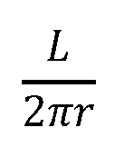
separated by a spacer of thickness t as shown in FIG.3. Similar to the binding of a book, in an embodiment, the strips are joined together on one end. In an embodiment, when the strips are in a flat orientation, the imaginary distance markings of the measuring tapes perfectly align. However, if the pair is formed around a cylinder of radius r, the inner tape measure will be formed into a circular arc of radius r, while the outer tape measure will be formed into a circular arc of radius r+t (as shown in FIG. 5 and discussed in more detail below). Because they are conjoined on one end, the zero markings of the two tape measures will still align, but the other markings will get progressively misaligned. This is because it takes more tape to subtend the same angle on a larger radius. In an embodiment, when a multibend sensor is formed around a circular arc, the radius r can be calculated knowing only the spacing and the relative shift between the tape measures. In an embodiment, relative shift can similarly be measured at many points along the sensor, each allowing us to measure the curvature of successive segments. In this way, we can measure complex curves that are well modelled as a series of circular arcs. [0076] Referring now to FIGs.3-5, when the multibend sensor is wrapped around an object in a circle, the inner of the two strips conforms to the circle, while the outer strip conforms to a slightly larger circle due to the thickness of the spacer 18. [0077] Because the two strips have different radii of curvature, the unconstrained ends will not align with each other. By knowing the length of the strips, sliding strip 12 and reference strip 14 and the thickness of the spacer 18, the radii can directly be calculated. If the relative shift between the two strips is measured at many places, a model of the bend as a series of circular arcs can be constructed. This provides a much better understanding of the shape of the bend as opposed to traditional sensors. [0078] Still referring to FIGs. 3-5, to illustrate the way in which the multibend sensor works, take two strips of length ^^^^, the sliding strip 12 and the reference strip 14 separated by a spacer 18 of thickness t. The sliding strip 12 and the reference strip 14 are joined together at end point 16 and cannot move relative to one another at that end. When the reference strip 14 is wrapped into a circle of radius ^^^^ as shown in FIG.4, the reference strip 14 will have a radius of curvature of r,, while the sliding strip 12 will have a smaller radius of r-t . [0079] The circumference of the circle is 2 πr. . The reference strip 14, which is of length ^^^^, covers a fraction of the circle:
[0080] To put it in terms of radians, the angle subtended by this strip is:
[0081] As shown in the diagram, when curled in the direction of the thickness measurement ^^^^, the sliding strip 12 ends up on the inside, with a smaller radius of curvature. The tighter wrap means that some of the sliding strip 12 extends beyond the end of the reference strip 14. If this continues along a circle of the same radius, the sliding strip 12 subtends an angle of:
[0082] The end of the reference strip 14 lines up with a corresponding point 30 on the inner sliding strip 12. To give a more precise definition, it is the intersection point on the sliding strip 12 to the normal constructed through the endpoint of the reference strip 14. [0083] This point can be found on the sliding strip 12 by finding the difference in the angular extent of the two arcs, finding the extending length S
s and subtracting this from the total length L.
[0084] The length of the segment Ss
of the sliding strip 12 that extends past the reference strip 14 can be found by dividing the angular extent in radians by 2 π to find the fraction of the circle and multiplying by the circumference.
[0085] Solving these equations for the radius r gives:
[0086] By measuring the relative shift between the strips, the radius of curvature across the length can be calculated using this simple equation. [0087] Now consider the case where bending occurs in a clockwise direction as shown in FIG.5.
[0088] The analysis proceeds much as before, but now the sliding strip 12 is on the outside, with a radius of curvature of
[0089] As before, the goal is to locate the corresponding point 31 on the sliding strip 12 that corresponds to the endpoint of the reference strip 14. However, because the sliding strip 12 is on the outside and thus subtends a smaller angle the arc has to be continued to find the intersecting point. S
s is calculated by finding the angle subtended and the corresponding length on the sliding strip 12.
[0090] This is the same result as obtained in the counterclockwise case. The difference here is that S
s in the first case is the amount the sliding strip 12 extended past the reference strip 14, and in this case, it is the amount extra that would be needed to reach the end of the reference strip 14. [0091] To combine these two cases, consider the radius of curvature to be a signed quantity, with a positive r indicating an arc which proceeds in a counterclockwise direction and a negative r indicating a clockwise direction. [0092] A new variable, L
s is defined as the total length along the sliding strip 12 to line up with the end of the reference strip 14. The signed radius of curvature is:
[0093] In FIG. gave a positive radius of curvature.
, gives
a negative radius of curvature. The signed radius of curvature is then used to find the signed angular extent of the reference strip.
[0094] In the following, all angles and radii of curvature are signed.
Reconstructing the Curve from Shift Measurements [0095] In an embodiment, the multibend sensor models shape as a series of circular arcs of different radii to allow for complex curves. By measuring the relative shift at many points along the strips, the curvature of each segment can be quickly determined. [0096] The multibend sensor 10 shown in FIG.6 comprises a sliding strip 12 and a reference strip 14. Finding the shape of the reference strip 14 is the goal. At fixed intervals along the reference strip the corresponding shifted position along the sliding strip 12 is measured. By corresponding, it is meant that points that lie at the same angle with respect to the common center of the radius of curvature are used. Another way to say this is that if a normal to the curve of the reference strip 14 is constructed at the measurement point, a measurement will be made where it intersects the sliding strip 12. [0097] Referring now to FIG.7A, a single circular arc segment that spans from n to n + 1 (segment ^^^^) on both the reference strip 14 and sliding strip 12 is provided as an example. Segment ^^^^ is shaped into a circular arc of radius
in a counterclockwise direction. Thus, the reference strip 14 has radius r [ n ] while the sliding strip is inside with a smaller radius of
Starting angle θ[ n ] is the tangent at the beginning of the arc. The ending angle is the tangent to the arc at its end, θ[ n + 1]. Similar to the calculation above,
is the length of the reference strip 14 to measurement point
is the length of the sliding strip 12 to measurement point n . On the side of the reference strip 14, the segment begins at
and ends at
Similarly, the corresponding sliding strip 12 extends from . The signed radius of curvature and the
signed angular extent of the reference strip 14 segment can be found. [0098] We define the length of the reference strip 14 in segment n as:
[0099] and the length of the corresponding sliding strip as:
[0100] Similarly, we define the total subtended angle of this segment as:
[0101] For the case of positive curvature and
, the sliding strip
12 is shaped into a tighter curve than the reference strip 14 Thus even
though they subtend the same angle, Working in radians, the length of the
reference segment is:
[0102] and the length of the corresponding sliding segment is:
[0103] Given the two lengths and the spacer thickness, we can solve for the radius of curvature of this segment:
[0104] This same equation applies when the curve proceeds clockwise, giving a negative ending angle and negative radius of curvature. We can also solve for the subtended angle of the arc:
[0105] A series of circular arcs of known length, angular extent, and radius of curvature is now known. This series can be pieced together to model the complete curve of the reference strip 14. It will be noted that, in an embodiment, multibend sensors have continuousflexure along their length and, thus, they are inherently continuous in their first derivative. Therefore, to maintain a continuousfirst derivative from segment to segment, the tangents of adjoining segments match. To put this another way, the ending angle of each segment matches the starting angle of the next segment. [0106] Consider a single arc as shown in FIG.7B. A starting angle and
an ending angle which are tangent to the arc at its endpoints can be
determined. It can be presumed that sequential segments connect smoothly – i.e., that the derivative is continuous at the point of connection. This is why the connection points are described by a single tangent angle. [
0107] The arc begins at a known starting point
and at an initial known angle 72 of
and proceeds to an unknown ending point
, at an unknown ending angle 7
[0108] The change in angle from starting point to the ending point is just the turning of the segment angle,
.To find the x, y translation, the increment in x and y over the arc is added to
of the arc is considered to be at the origin and used to calculate endpoint positions. The difference in these is then applied to the known starting point. [0109] For this calculation, the angles from the center that form the arc are known. The normal to For an arc of positive radius of curvature, this gives the
angle pointing out from the center of the radius of curvature. If the radius of curvature is negative, it points in the opposite direction. This results in a sign flip that is corrected by using the signed radius of curvature. The endpoints can then be found iteratively via these equations:
[0110] These equations can be slightly simplified using trig identities.
[0111] These equations describe the series of circular arcs that model the bend. A
circular arc is typically described by its center
, its radius of curvature a starting angle, and an angular extent
[
0112] The center of an arc segment can be found by starting at
, and following the radius to the arc center
The starting angle is found from the normal at the point
which is The center is then:
[0113] Note that the use of the signed radius of curvature ensures following the normal to the center. [0114] The starting angle is:
[0115] The sign is needed to flip the angle if the arc proceeds clockwise. The extent of the arc which is also a signed value.

Sensitivity to Measurement Error [0116] Any real measurement of shift will be imperfect, making it important to understand how measurement errors impact the accuracy of the modelled curve. In jointed arms, noisy measurements of joint angles quickly accumulate, causing significant errors in the final position of the end effector. For instance, on multi-axis robot arms, position is usually determined via a series of encoders - one on each joint. High precision encoders are typically required because any errors in each joint measurement accumulate. For a planar arm, the angular error at the end of the arm is simply the sum of all the measurement errors in each joint. The location error of the endpoint is also wildly impacted by all of the joint errors-particularly the ones at the beginning of the arm. [0117] Measurement errors in the multibend sensor are more forgiving. In an embodiment, error propagation is mitigated because measurement errors for each arc are not independent. [0118] Consider the case of a single shift measurement error at the nth point. Compared to the ideal, the shifted point will cause an error in the radius of curvature of two adjacent segments. The error on one segment will be one direction, while the error on the other segment will be in the opposite direction, tending to cancel things out to first order. This property, of segment errors tending to create somewhat compensating errors, holds in general and is a consequence of the shift measurements which give the total accumulated shift to that point. [0119] To show the sensitivity to error, take the example of two successive
segments with the coordinates:
[0120] Ideal measurements for L
r [ n ] and L
s [ n ] are given. However, L
s [1] will be
perturbed by a measurement error of δ. How this error propagates to
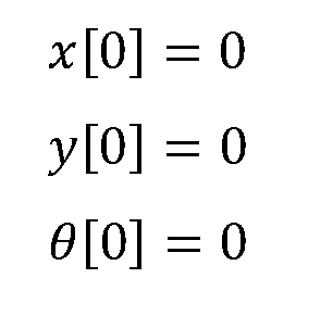
is then found. [0121] In the unperturbed case (and noting that θ [0] = 0):
[0122] Equally spaced measurement points, 1 unit apart are presumed.
[0123] Apostrophes are used to indicate the variables for the case with measurement error
This allows the resulting angles with and without mid-point measurement error to be.
[0124] This shows that the ending angle after two arcs is unimpacted by a misreading in the middle point. The angle error does not propagate. [0125] The error in the point locations is considered.


[0126] Using these equations, the endpoint error under different conditions can be plotted. It is clear that position error at the end of the first segment is somewhat compensated for by an oppositely signed error in the next segment. [0127] Further consider the case of a multibend sensor with two measurement points. The curvature of the first segment is found by determining the relative shift at the first measurement point. In this example, the measurement is corrupted by noise and an incorrectly low shift reading is recorded. The relative shift of the second segment is then found by taking the total shift at the second measurement point and subtracting off the shift from thefirst measurement point. The error at thefirst point will now cause a corresponding error in the second segment that is opposite in sign from the error in the first segment. Thus, the two segments will end up with curvature errors that tend to cancel each other out. In an embodiment, the error infinal angle is completely unimpacted by the error at thefirst measurement point. [0128] To show the sensitivity to error, we revisit the example of two successive segments. We define the starting point of the curve as:
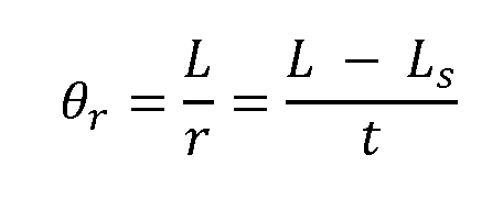
[0129] By definition, We can now calculate the ending
angle of segment 0:
[0130] Next, wefind the ending angle of segment 1.

[0131] As can be seen, the ending angle calculation has no dependence on any earlier measurements. This means that any errors in earlier measurements do not contribute error in the ending angle of each segment. [0132] While the embodiment and examples discussed above uses arcs in performing the analysis, other measurement techniques and analyses may be employed. In an embodiment, ellipses are used for approximating the curves. In an embodiment, analysis of the curves may be performed using parabolas. In an embodiment, splines are used for approximating a curve. In an embodiment, a polynomial function is used for approximating the curve. In an embodiment, all of the methodologies discussed herein are used in approximating the curve. [0133] As will be noted by those skilled in the art, the above noted results prove advantageous over traditional solutions that build upon a series of angular encoders which have a practical limit on the number of encoders that can be strung together. [0134] Another possible model of a curve is to represent it as a series of connected straight linear segments. [0135] Referring to FIGs. 8 and 9, for a piecewise linear model, the bends are presumed to be perfectly sharp, and occur only at fixed intervals on a reference strip 84. The sliding strip 82 will be presumed to conform to a fixed distance from the reference strip 84. This will create corresponding sharp bends for each bend of the reference strip 84. Bending towards the reference strip 84 will mean that extra length will be needed on the sliding strip 82 to conform to the new shape. Similarly, bending towards the sliding strip 82 will take less length to conform. [0136] The calculation is begun by calculating the extra length required on the sliding strip 82 given a bend toward the reference strip 84. Looking towards FIG.9, the multibend sensor has a bend of angle A. The vertically opposite angle is also A. The extra length of the sliding strip 82 needed to conform to the bend is shown as 2 s . The two bend points bisect the bend angle. The vertically opposite angle is also With the
right angle construction the A − 90 angle is found by subtracting the right angle Finally
the angle opposite s is computed as . The tangent of this angle is equal to
the opposite side length (s) divided by the adjacent side length (t).
[0137] And for the total length added:
[0138] This formula is also correct for when the bend angle exceeds 180, and bends up towards the sliding strip 82. In this case the additional length is negative. [0139] For convenience, the bending angle, B, can be defined relative to no bend being 0.
[0140] Substituting in:
[0141] Given a measurement of shift, the angle that would have given rise to it is calculated.
[0142] Like the circular arc model, this piecewise linear model still has the general behavior of measurement error in one shift measurement creating a complementary error in the next, partially canceling out the impact of potential additive error. [0143] Consider an ideal measurement vs one where there is measurement error in the first segment.
[0144] The resulting angle of the last segment is simply the sum of the angle to that point.
[0145] Repeating the calculation with measurement error:
[0146] These total bends are not the same, however, it can be shown via series expansion around ^^^^ = 0that the errors cancel to first order. Capacitive Sensing Techniques [0147] Capacitive sensing can be used with a multibend sensor and is the methodology discussed above with respect to FIGs. 1-2. For example, looking to FIG. 10, a pattern of interdigitated electrodes 20 allows one to perform differential measurements by comparing the capacitance of overlapping electrodes 20 to determine relative shift. The differential nature of this measurement makes it highly insensitive to various types of error. In addition to the electrode pattern shown in FIG. 10, other electrode patterns can be implemented that will further provide measurements that can help determine the overall movement and shape of the multibend sensor. [0148] Still referring to FIG. 10, a plurality of the electrodes 20 are adapted to transmit signals and a plurality of the electrodes 20 are adapted to receive signals from the electrodes 20 that are transmitting signals. In an embodiment, the electrodes 20 adapted to transmit signals and the electrodes 20 adapted to receive signals may be switched or alternated depending on the implementations. In an embodiment, an electrode 20 adapted to transmit a signal may, at a different time, also be adapted to receive a signal. Received signals are used in order to determine movement of one strip with respect to the other strip. [0149] In an embodiment, orthogonal frequency division multiplexing can be used with a multibend sensor employing a plurality of electrodes 20 that are adapted to receive and transmit orthogonal signals. In an embodiment, unique frequency orthogonal signals are used. In an embodiment, a unique frequency orthogonal signal is transmitted on each of the electrodes 20 that is transmitting. Electrodes 20 that are adapted to receive signals may receive t
regarding the relative shift of the reference strip with respect to the sliding strip. This can then be used to determine the shape of the curve formed by the multibend sensor. [0150] In general, the curvature of multiple dimensions can be determined by forming a mesh of reference strips and sliding strips with each multibend sensor determining its own respective curve. After the curve of each multibend sensor is determined the entire curvature of a plane can be modeled. In an embodiment, a plurality of multibend sensors may be placed on a three dimensional object that is subject to various deformations across its 3D surface. The plurality of multibend sensors may be able to accurately determine the curving deformation of a 3D object after reconstructing curvature taken from each of the multibend sensors. [0151] In another embodiment, the strips are replaced with fibers that are flexible in 3 dimensions. These fibers are then packed around a central reference fiber such that the outer sliding fibers move relative to the reference fiber when bent. In an embodiment, spacers maintain a constant spacing between all the fibers. The relative shifts can be measured by a variety of means, including via patterned electrodes along the fiber. [0152] In an embodiment the sensor may be created from narrow sheets that more closely resemble a flexible wire, being able to flex outside of the plane. If two of these devices are held together, sensing in orthogonal directions, flexing in and out of the plane can be measured. [0153] Another embodiment is shown in FIG. 11. This embodiment provides a multibend sensor 110 that is able to determine curvature in more than one planar direction. There is a sliding plane 112 and a reference plane 114. In FIG.11 the planes are not shown on top of each other however, it should be understood that this is for ease of viewing the planes, sliding plane 112 and the reference plane 114 are positioned with respect to each other in a similar manner in which the strips discussed above are positioned. Electrodes 115 are placed on the sliding plane 112 and the reference plane 114. In FIG.11, the electrodes 115 are formed as rows and columns. In an embodiment, the electrodes are formed as pads. In an embodiment, the electrodes are formed as dot antennas. There may additionally be a spacer plane placed between the sliding plane 112 and the reference plane 114 in order to establish a distance between the sliding plane 112 and the reference plane 114. In an embodiment, the reference plane 114 and the sliding plane 112 are implemented without a spacer layer with the electrodes 115 placed on the outward facing surfaces with the substrates of the planes functioning as a
spacer layer. Furthermore, while there may be electrodes 115 placed on both planes, there may be transmitting electrodes placed on the sliding plane 112 and the reference plane 114 and receiving electrodes located at an interstitial region between the two planes. Also, the electrodes 115 can be either transmitting or receiving. [0154] Still referring to FIG.11, the sliding plane 112 and the reference plane 114 are flexible planes that are able to bend. The reference plane 114 and the sliding plane 112 are attached at various attachment points. Attachment points may be located at any location between the planes provided that they establish a reference location by which to ascertain the movement of one plane with respect to the other. In an embodiment, the attachment point may be the center location of the planes. In an embodiment, there are more than one attachment point from which relative movement of the planes is established. In an embodiment the planes are secured to each other at an edge. In an embodiment, the planes are secured at multiple points along the edge. In an embodiment, the planes are secured at points along an edge and within the area of the planes. [0155] Turning to FIGs.12 and 13, another embodiment of a capacitive electrode design to measure relative shift is shown. While multilayer flex circuits are widely available, there are certain limitations to design that may be imposed. A common restriction is to not allow vias on bending sections. Therefore, patterns which do not require interlayer connections in bending areas are sometimes preferred. [0156] FIG. 12 shows two triangular electrodes 120 that form the reference strip 124, and a series of rectangular electrodes 121 formed on the sliding strip 122. By measuring the relative capacitance to the A electrode 120 and B electrode 120 for each of the rectangular electrodes 121 on the sliding strip 122, the relative position of the rectangular electrodes 121 can be determined. [0157] This pattern shown in FIGs. 12 and 13 does not require multiple layer connections. On the reference strip 124, connections can be directly made from either end. The rectangular electrodes 121 on the sliding strip 122 can be made via bus 126 as shown in FIG.13. In an embodiment, shielding can be employed around the rectangular electrodes 121 and the triangular electrodes 120. Shielding can assist in mitigating interference. Electrodes that are transmitting can be surrounded by ground and receiving electrodes can be driven with an active shield in order to mitigate interference.
[0158] The design shown in FIGs.12 and 13 is sensitive to slight rotations between the reference strip 124 and the sliding strip 122. For example, if the spacing is greater on the top versus the bottom, it may cause a systematic error. This can be corrected by calibration. Sensitivity can also be ameliorated by using a less sensitive pattern. [0159] An example of a pattern with reduced sensitivity is shown in FIG.14. The pattern shown in FIG. 14 employs additional triangular electrodes 140 placed on the reference strip 144. Rectangular electrodes 141 are placed on the sliding strip 142. The electrode pattern shown in FIG. 14 is symmetric about the centerline of the reference strip 144. This reduces the sensitivity as compared to the pattern shown in FIG.12. The reduced sensitivity occurs because the triangular electrode 140 is further away on one side and closer on the other side. This distance roughly balances out the impact of any tilt that may exist. [0160] FIG.15 shows another embodiment of sensor electrodes. FIG.15 shows an arrangement of a reference strip 154 and sliding strip 152. The reference strip 154 has a plurality of triangular electrodes 150. The sliding strip 152 has a plurality of rectangular electrodes 151. In comparison to the electrode pattern shown in FIG.12, the pattern in FIG.15 replicates that arrangement of triangular electrodes 150. The angled pattern is replicated on a smaller scale in the neighborhood of each measurement to improve resolution. The sensor pattern shown in FIG. 15 can also be combined with shielding and symmetry techniques. [0161] FIG.16 shows another embodiment of sensor electrodes. FIG.16 shows an arrangement of a reference strip 164 and sliding strip 162. The reference strip 164 has a plurality of triangular electrodes 160. The sliding strip 162 has a plurality of rectangular electrodes 161. In comparison to the electrode pattern shown in FIG.12, the pattern in FIG.16 replicates that arrangement of triangular electrodes 160. The angled pattern is replicated on a smaller scale in the neighborhood of each measurement so as to improve resolution. The sensor pattern shown in FIG.16 can also be combined with shielding and symmetry techniques. When shifting causes a rectangular electrode 161 to get near the end of a triangular electrode 160, some nonlinearity will result. A way to address this is to use multiple sets of the triangular electrodes 160. The sets are shifted so that when a rectangular electrode 161 is near an edge on one triangular electrode 160, it is not at an edge on another of the triangular electrode 160.
Optical [0162] In addition to capacitive based sensing, multibend sensors can be created using optical techniques rather than capacitive. Instead of interdigitated electrodes, optical transmitters and receivers can be used. Signals can be transmitted through an optically transmissive spacer located between a reference strip and sliding strip. Waveguide techniques permit the electronics to be placed at one end, rather than distributing them along the sensor. [0163] Using standard flex circuit techniques, it is possible to place standard electro-optic components such as LEDs and photodiodes on a flexible strip. However, because these components are not in and of themselves flexible, local stiffening at the measurement point may be needed. Certain techniques may be used to work around the issue of local stiffening. In general, flexible electronics can be applied to the manufacture of multibend sensors (e.g., doing local electric field sensing, and reporting data back via a shared bus). In particular, the availability of OLEDs and other optic devices in a flexible form makes it possible to build distributed optical encoders along a flexible strip. [0164] Flexible waveguides may also be employed to bring the optical signal to and from the measurement points distributed along the strips. In this way, the optoelectronics can be gathered at one location. For example, the optoelectronics can be placed at the end where the strips are joined. At this location a rigid PCB can hold the electro-optic components. [0165] Additionally, to cut down on the required number of optical connections, multiplexing techniques can be employed. For example, each sense location could employ optical filters so that different colors of light, different polarizations, or some combination of these are active at different locations along the multibend sensors, and can be distinguished at the end with the opto-electronics. [0166] These systems have a path for light to travel from one strip to the other. This can be accommodated several different ways. In an embodiment, the spacer may be made from transparent materials. In an embodiment, slots may be provided in the neighborhood of the measuring spots. In an embodiment, the spacer may maintain an air gap between the strips. In an embodiment, the optical fibers may have nicks that permit light to bleed from one cable to another. In an embodiment, there may be bundles of optical fibers that are tied in the middle wherein the relative shift of both ends of the bundles are able to be determined
[0167] Referring to FIG.17, inexpensive camera chips also can be used to make multibend sensors. These chips could be used at various points along the strips so as to measure shift. Still referring to FIG.17, multiple, parallel sliding strips 172 are used that attach to a reference strip 174 at staggered attachment points 176. The ends of these sliding strips 172 can then extend to be observed by a camera chip 175. A single camera can thus track the motion of multiple slide strips 172 with high precision, effectively giving the same result as measuring the shift at different locations. [0168] While flexible electronics are an option, there are other options for distributing optoelectronics along a flexible strip. In an embodiment, a rigid PCB may be attached to a flexible strip via elastic members. In this way, the strip can still bend freely, while the floating electro-optic module looks toward the encoder markings on the other flexible strip. To help maintain alignment, the electro-optic module can be designed to have a larger optical area that looks through a smaller aperture in the flexible strip. Even if the rigid PCB slightly wiggles with respect to the strip, the measurement will always be done with respect to the aperture in the strip. [0169] When sensing shift, there is a question of how much shift must one sense before running out of range. Looking to the arrangement of receiving electrodes 182 and transmitting electrodes 184 shown in FIG. 18 an example of shifting range can be explained. In this case, there are a small number of receiving electrodes 182 that are placed on a sliding strip, and a larger number of transmitting electrodes 184 placed on a reference strip. Instead of providing unique signals on every transmitting electrode 184, signals are reused periodically. Each of the numbered transmitting electrodes 184 representing a different signal. If the shift is limited to the region of one set of transmitting electrodes 184, the position can be uniquely determined. If the shift is greater than this, the shift reading is not uniquely determined by the closest transmitting electrode 184. In this instance it could have shifted so much as to have wrapped into the next set of transmitting electrodes 184. Because a sequence of measurements is made along the strips, the combined shift from earlier segments can be seen and is likely to indicate that a wrap has occurred. Because incremental unwrapping can occur, the constraint is not on any particular receiving electrode 182 staying within range of one set of transmitting electrodes 184. It is only limited by the ability to unwrap. If it is known that the number of transmitting electrodes 184 between successive receiving electrodes 182 is limited to +/- half the number of receiving electrodes 182 nominally between transmitting electrodes
184 one can uniquely determine the position of the next segment because it is known which transmitting electrodes 184 could be within the range of the previous segment. More sophisticated techniques can extend this even further for example, by making assumptions about higher order derivatives. Although this technique is explained in the context of a capacitive sensor, the same technique can be applied to other embodiments. Using the optical multistrip setup, instead of just detecting an end, the strip can have repeated variations which are detected and analyzed to find a precise position. It is possible to use calibration targets with many edges to allow the positions to be determined by combining data of all of them. Other Methodologies [0170] Above, capacitive and optical techniques were discussed, however, other mechanisms may be employed. For example, similar to a potentiometer, one strip can serve as a distributed resistor, and the other may have multiple wipers that make contact at numerous points along the resistive strip. The voltage at each wiper can be arranged to indicate the relative position along the resistive strip. A resistive strip is located on one strip, and a voltage placed across it. This creates a voltage gradient along the strip that is position dependent. Wipers along the top strip make sliding contact with the strip, sensing the voltage at their location. The wrapping detection discussed above can be achieved by having a separate potentiometer formed in the region of each wiper to allow more precise measurements. Mechanically, the wipers could also play a role in maintaining the spacing between the layers since they are spacers in and of themselves. [0171] An improvement on the above design is rather than having a single resistive stripe along the strip, separate ones may be placed in the neighborhood of each wiper. Then each smaller resistive stripe could have the entire voltage gradient over a much smaller displacement, greatly increasing the resolution of the measurement. It should be noted that the number of connections to the strip with the resistive stripes is still only two. [0172] Rather than mechanical wipers, other methods can be employed to create shift-dependent resistivity changes. For example, magneto-resistive materials change resistance in the presence of a magnetic field. A resistive trace, running parallel to a conductor could be effectively bridged at different locations including magneto-resistive material between these traces, which can be selectively made more conductive by a magnet on the other strip.
[0173] Another embodiment employs a series of magnets on one strip and Hall effect sensors on the other in order to measure shift. Time domain techniques may also be utilized to measure length. Time domain reflectometry techniques in either the electrical, optical or acoustic domain can be used to measure shift at multiple points. To use these, the measurement points create a path for signal to return. Magneto strictive position transducer methods may also be used to measure shift. [0174] In an embodiment, inductive proximity sensing can be employed. The inductance of a coil will change in response to certain materials being within proximity to them. For example, in an embodiment, one strip carries a series of coils, while the other has sections of different magnetic permeability that are detected by the coils. The detection can be done a number of ways, including noting the change in inductance of each coil independently, or looking for the change in coupling among different coils. It is also possible to have coils on both strips, and measure the coupling between them. Linear Variable Differential Transformers (LVDTs) can be straightforwardly applied to this type of measurement. [0175] In an embodiment, electromagnetic coupling can be utilized using radio frequency (RF) coupling between the strips. [0176] In an embodiment, multibend sensors are designed for remote interrogation via RF. A simple tank circuit (LC) is used where either the L or C are dependent on the relative shift between strips. This type of circuit can be created on the strips using only patterning of conductive material. The resonant frequency of the tank circuit is dependent on relative shift, and can be read remotely using standard RFID techniques. The strips can be designed so as to contain multiple resonances that are each dependent on the local relative shift. If the resonances are reasonably separated in frequency, a remote frequency scan can reveal the change in each resonance independently. With the addition of active components, other techniques, such as time domain multiplexing can be employed to read the shift over multiple points. [0177] Magnetic sensors (Hall effect, Giant Magnetoresistive, etc.) can be used to measure local magnetic fields. A pattern of magnetization of one strip could be detected on the other to determine relative shift at many points. Magnetic circuits can be employed to bring the flux measurement to a convenient physical location. High magnetic permeability material serves to channel the flux similar to a conductive wire carrying electric current Using these techniques a number of magnetic sensors can be positioned
on the conjoined end of the strips, making measurements at various points along the strips. [0178] Magnetostrictive transducers have been employed for measuring position in harsh industrial environments. The position of a moving magnet is determined by pulsing current in a magnetostrictive element, which causes a mechanical impulse to be generated in the element in the region of the magnet. The time for this impulse to propagate back to a measurement point is a function of the position of the magnet. In an embodiment, magnets are placed on one strip, and magnetostrictive material is placed on the other. [0179] Analogous techniques can be employed using photoconductive materials. A light on the sliding strip can shift the location of bridging. This could be an LED or other light source mounted on the strip, or a simple aperture through which a separate light source is allowed to selectively pass. [0180] Some of the measurement error propagation properties of the multibend sensor can be obtained on more traditional arm/encoder systems through mechanical means. Parallel linkages are often used to maintain the parallelity of two members. [0181] FIG. 19, shows three sets of parallel linkages that guarantee that the horizontal lines remain parallel to each other. The dots 1901 represent encoders. The angle measured at each encoder is always with respect to the top line. In this way, measurement errors at each encoder do not propagate in measuring the absolute exit angle at each encoder. Various combinations of gears, belts and other linkages can be employed to similar effect. [0182] The above discussed multibend sensors provide curvature data along its length. This data can be used in more sophisticated ways to give more detailed models. For example, one can interpolate or fit a higher order function to model the change in curvature along the sensor, and thus create a model with effectively many more segments. One could also change the underlying model of a segment from a circular arc to a different functional form. [0183] The above described embodiments of the multibend sensor can accurately determine the shape of a curve or curved surface. Some applications of this technique may be in determining the positioning of robotics systems. In an embodiment the multibend sensor is used for pliable interfaces. In an embodiment the multibend sensor is used for human joint motion rehabilitation In an embodiment the multibend sensor is
used for human joint motion in virtual reality. In an embodiment, the multibend sensor is used for determining curvature of a back, movement of a head, or bending of legs. In an embodiment the multibend sensor is used for measuring complex curves. In an embodiment the multibend sensor is used for complex vibration understanding and active control. In an embodiment the multibend sensor is used for automotive, tires and seat deformation. In an embodiment the multibend sensor is used for posture monitoring. In an embodiment the multibend sensor is used for expressive musical instrument interfaces. In an embodiment the multibend sensor is used for tank/pressure bladder monitoring for deformations such as bubbling out (e.g., monitoring planes, submarines etc.). [0184] The multibend sensor may also be used in understanding the shape of a pressurized system. For example, airplanes with pressurized cabins undergo significant stress and deformation as they are repeatedly pressurized and depressurized. If a particular area becomes weakened through repeated stress, it will begin to bubble out (or in, depending on which side you are looking at) relative to other areas. The multibend sensor is employed so as to detect this for understanding the rate of system fatigue, and where failures may be imminent. Submarines, holding tanks, and all sorts of pressurized containers have similar issues that can benefit from the application of the multibend sensor. In an embodiment, the multibend sensor is used in assisting with oil and gas exploration when determining the curvature of bits. [0185] Other mechanical systems that deform under load can also benefit from the multibend sensor. Another advantage of the multibend sensors described above is that the precision arises from geometric relationships rather than from electrical properties that are susceptible to changes due to environmental conditions and are subject to aging and wear, this makes the disclosed multibend sensors suitable for monitoring bridges, support beams, etc. over the life of the structure. [0186] Another advantage of the multibend sensors described above is that the precision arises from geometric relationships rather than from electrical properties that are susceptible to changes due to environmental conditions and subject to aging and wear. Implementations of this application may employ principles used in implementing orthogonal frequency division multiplexing sensors and other interfaces disclosed in the following: U.S. Patent Nos.9,933,880; 9,019,224; 9,811,214; 9,804,721; 9,710,113; and 9,158,411. Familiarity with the disclosure concepts and nomenclature within these
patents is presumed. The entire disclosure of those patents and the applications incorporated therein by reference are incorporated herein by reference. This application may also employ principles used in fast multi-touch sensors and other interfaces disclosed in the following: U.S. patent applications 15/162,240; 15/690,234; 15/195,675; 15/200,642; 15/821,677; 15/904,953; 15/905,465; 15/943,221; 62/540,458, 62/575,005, 62/621,117, 62/619,656 and PCT publication PCT/US2017/050547, familiarity with the disclosures, concepts and nomenclature therein is presumed. The entire disclosure of those applications and the applications incorporated therein by reference are incorporated herein by reference. Physical Implementation [0187] Referring now to FIGs.20A and 20B, a reference strip and a sliding strip of a multibend sensor are provided. A plurality of transmit electrodes moves along a corresponding pattern of receive electrodes. In an embodiment, position is determined by examining the change in coupling capacitance between the transmit and receive electrodes. In an embodiment, a pattern of interdigitated electrodes allows one to perform differential measurements by comparing the capacitance of overlapping electrodes to determine relative shift. The differential nature of this measurement makes it highly insensitive to various types of error. As noted above, in addition to the electrode pattern shown in FIG.20A, other electrode patterns can be implemented that will further provide measurements that can help determine the overall movement and shape of the multibend sensor. [0188] In an embodiment, a plurality of the electrodes are adapted to transmit signals and a plurality of the electrodes are adapted to receive signals from the electrodes that are transmitting signals. In an embodiment, the electrodes adapted to transmit signals and the electrodes adapted to receive signals may be switched or alternated depending on the implementations. In an embodiment, an electrode adapted to transmit a signal may at a different time also be adapted to receive a signal. Received signals are used in order to determine movement of one strip with respect to the other strip. In an embodiment, electrodes can be patterned on standard flexible printed circuit boards (PCB) when creating the reference strip and the sliding strip. The capacitance through the spacer can be measured, and relative position determined. [0189] In an embodiment, the transmit strip has a plurality of equally spaced electrodes which align with an equal number of differential electrode pairs on the receive
strip. When the strips areflat, each transmit electrode will be centered over a receive pair such that the differential capacitance is zero. As the two strips shift relative to each other, the transmit pads will move out of alignment with the receive pads, unbalancing the differential capacitance. In an embodiment, the electrodes are arranged as to have significant overlap to minimize the impact of skew and fringingfields, giving a linear change in differential capacitance with respect to shift. [0190] In an embodiment, the transmit and receive pads are kept at afixed spacing by interposing a plurality of polyimide strips. In an embodiment, the amount of shift is proportional to the thickness of the spacing. In an embodiment, the thickness is 0.5 mm. In an embodiment, a single spacer is used. In an embodiment, a plurality of spacers are used to maintain accurate spacing while allowing the device to be pliable. [0191] In an embodiment, the strips are held pressed together via an elastic sleeve, while still allowing them to shift against each other along the length. In an embodiment, a clamp passes through alignment holes on the strips to constrain motion on that end. In an embodiment, goldfinger contacts allow the strips to be inserted into connectors on opposite sides of a controller board. In an embodiment, the strips are integrally manufactured with a controller board. [0192] FIGs.21A and 21B show a perspective view and a side view, respectively, of a multibend sensor 2100. In an embodiment, the sliding strip and the reference strip are portions of a single continuous component that is then folded onto itself. In an embodiment at least one spacer is located between the sliding strip portion and the reference strip portion. [0193] In an embodiment, the electrical connections for the electrodes (not shown) placed in the sliding and reference portions may be routed back through one or both ends of the continuous component to the circuitry. In an embodiment, the electrodes belonging to the sliding portion and those belonging to the reference portion are affixed to a continuous piece of material with all electrical connections routed to one or both ends. The continuous piece of material would then be folded and the ends secured to each other. In an embodiment, at least one spacer is placed between the sliding and reference portions and secured to the ends of the material. [0194] FIGs.22A and 22B illustrate a multibend sensor in a flat position and a bent position, respectively. In an embodiment, the electrodes shift as the sensor isflexed. FIG. 22C illustrates the relationship between the relative shift and differential capacitance
when the multibend sensor is in a flat position and in a bent position. In an embodiment, when the multibend sensor is in a flat position, the transmit electrodes are centered between two receive electrodes (i.e., no shift) and the differential capacitance is zero. In an embodiment, when the multibend sensor is bent in at least a portion of the sensor, at least one transmit electrode overlaps one receive electrode from the set of receive electrodes more than the other(s) receive electrode(s) (i.e., shift) creating a non-zero differential capacitance. [0195] In an embodiment, a single channel, 24-bit differential capacitance to digital converter is used to perform the capacitance measurements. In an embodiment, using a series of ultra-low capacitance multiplexers, shift at 8 points along the strips can be successively measured. In an embodiment, the capacitances measured are sub-pico farad. [0196] In an embodiment, when substantial parasitic capacitances due to the proximity of various traces are noted, a calibration procedure can be used. First, the static impact of the parasitic capacitances are measured when the sensor is laidflat. Then, this value is subtracted off of later readings tofind the differential capacitance due to the electrodes. In an embodiment, the circuit can do a full sweep of the multibend sensor about 10 times per second, while drawing less than 100mW. Palmband Sensor [0197] Turning to FIGs.23 - 25, a palmband 2300 capable of tracking hand pose and finger strikes is illustrated. In an embodiment, multibend sensors running up the fingers integrate shape-tracking and isometric-feedback technology to provide intelligent resistance to finger movement. In an embodiment, the palmband 2300 is capable of simulating the “feeling” of typing without the need for physical keys (i.e. no need for bulky haptic mechanisms at each finger.) In an embodiment, a user can type on any surface or in air with programmable keycap resistance haptics. [0198] In an embodiment, a shape-haptic palmband 2300 combines low-latency hand pose and finger strike tracking with shape-based resistive feedback on individual fingers. In an embodiment, the palmband 2300 can mimic the feeling of striking physical keys. In an embodiment, the palmband 2300 comprises an electronics hub 2310 that sits on top of the hand. In an embodiment, the hub 2310 is readily strapped by a strap 2315 around the palm. In an embodiment, the palmband 2300 comprises at least one sensor strip 2320 that runs up at least one of the index ring middle and pinky fingers In an
embodiment, the at least one sensor strip 2320 runs up the finger on the outside of the hand. In an embodiment, the at least one sensor strip 2320 runs up the finger on the inside of the hand. In an embodiment, the at least one sensor strip 2320 terminates at a fingertip. In an embodiment, the at least one sensor strip 2320 terminates at a finger tip with stretchable fabric finger cups 2325. In an embodiment, the at least one sensor strip 2320 comprises a set of retractable smart textile strips. In an embodiment, the palmband 2320 comprises at least one sensor strip 2320 that runs up a thumb. In an embodiment, the hub 2310 comprises thumb support structure 2313. In an embodiment, the hub 2310 and the thumb support structure 2313 form a single component. [0199] In an embodiment, the palmband 2300 comprises at least one multibend sensor, as disclosed herein, to accurately measure finger curl and strike on any surface. In an embodiment, the multibend sensor strips 2320 comprises a resistance system to provide shape-tracking and isometric-feedback technology to provide intelligent resistance to finger movement that can, for example, simulate the “feeling” of typing without the need for physical keys. In an embodiment, sensing and mechanical resistance are provided by a thin multibend actuator strip, removing the need for bulky mechanisms at each finger. In an embodiment, haptic feedback is provided by a clutch mechanism capable of providing resistance to finger movement. In an embodiment, haptic feedback is provided by a system capable of applying electroadhesion principles to resist finger movement. In an embodiment, the strips 2320 are anchored to at least one of the hub 2310 and the structure 2313. [0200] In an embodiment, the palmband 2300 comprises an actuator running the length of the finger. In an embodiment, the palmband 2300 comprises an actuator secured to a portion of the finger. In an embodiment, the palmband 2300 comprises a resistance element. In an embodiment, the actuator is a metal piece (i.e., wire, strip) running the length of a finger and connected to a resistance element. In an embodiment, the resistance element and the actuator are the same component (e.g., an electroadhesion system). In an embodiment, the resistance element and the actuator are the different components (e.g., a cable and clutch system). In an embodiment, each finger has a dedicated multibend sensor/resistance system. In an embodiment, the multibend sensor, actuator, and resistance element are one component. In an embodiment, the multibend sensor, actuator, and resistance element are different components.
[0201] In an embodiment, the palmband 2300 creates a “virtual striking surface” that can be programmatically defined and provide “felt” resistance. In an embodiment, haptic feedback is provided by a ferrofluid mechanism capable of providing resistance to finger movement. In an embodiment, the palmband 2300 creates a virtual object, for instance an apple or a pencil. By applying different levels of resistance to each finger at different points throughout the finger, the palmband 2300 can recreate the “feeling” of holding an object in that hand. The multibend sensors provide the palmband with feedback on the position of each finger and each part of each finger. [0202] In an embodiment, the haptic feedback comprises a hard stop. In an embodiment, the haptic feedback comprises a click through profile where the user experiences the sensation of pressing on a mechanical key. In an embodiment, the sensation of pressing on a mechanical key comprises an initial resistance followed by a greater resistance than the initial resistance, and a final resistance less than the greater resistance. [0203] An aspect of the present invention is a palmband comprising a multibend sensor secured to at least a portion of a finger of a user, wherein the multibend sensor is adapted to output at least one signal related to a movement or a pose of the finger. The palmband further comprises a processor operatively connected to the multibend sensor such that it can receive the output signals from the multibend sensor thereby. The processor uses the received signals to determine a characteristic of the movement or pose of the finger. The palmband also comprises a resistance system comprising an actuator secured to at least a portion of the finger of the user, and a resistance element mechanically connected to the actuator and operatively connected to the processor, wherein the resistance element provides an opposing force to the movement or pose of the finger based on the characteristic determined by the processor. [0204] Another aspect of the inventions is a palmband comprising a plurality of multibend sensors, each multibend sensor secured to at least a portion of a finger of a hand, wherein each multibend sensor of the plurality of multibend sensors is secured to a different finger of the hand, and wherein each multibend sensor is adapted to output at least one signal related to a movement or a pose of the hand; and, a processor operatively connected to the plurality of multibend sensors such that it can receive the output signals from the multibend sensors thereby, and use the received output signals to determine a characteristic of the movement or pose of the finger The palmband further
comprises a resistance system comprising a plurality of actuators corresponding to the plurality of multibend sensors, each actuator secured to at least a portion of a corresponding finger of the hand, and a resistance element mechanically connected to the plurality of actuators and operatively connected to the processor, wherein the resistance element provides an opposing force to the movement or pose of the hand based on the characteristic determined by the processor. [0205] Yet another aspect of the invention is a palmband comprising a multibend sensor secured to at least a portion of a finger of a user, the multibend sensor comprising a reference strip having a first plurality of electrodes, wherein each of the first plurality of electrodes is adapted to receive a signal; and a sliding strip having a second plurality of electrodes, wherein each of the second plurality of electrodes is adapted to transmit at least one signal, wherein the reference strip and the sliding strip are adapted to flexibly move in at least one dimension with respect to each other. The palmband further comprises a resistance system comprising an actuator secured to at least a portion of the finger of the user, and a resistance element mechanically connected to the actuator; and a processor operatively connected to the first plurality of electrodes, the second plurality of electrodes and the resistance element, the processor adapted to process signals received by the first plurality of electrodes, wherein the processed signals provide information regarding a movement or a pose of the finger, and further adapted to direct the resistance element to provide a resistance level to the finger based on the information regarding the movement or pose. Rollup Keyboard [0206] Turning to FIGs. 26-27, a multi-modal input surface 2600 is illustrated. In an embodiment, a multi-modal input surface 2600 is capable of packing into a cylinder 2650. In an embodiment, the cylinder measures approximately ~50 mm in diameter and ~110 mm in length. In an embodiment, the cylinder measures approximately ~25 mm in diameter and ~300 mm in length. As it will be apparent to those skilled in the art, the shape of the body into which the multi-modal input surface 2600 is inserted is non- limiting. In an embodiment, multi-modal input surface 2600 is capable of packing into a hollow body. [0207] In an embodiment, the multi-modal input surface 2600 can be used as a keyboard. In an embodiment, the multi-modal input surface 2600 can be used as a multi- touch mouse In an embodiment the multi modal input surface 2600 comprises
collapsible mechanical-feedback keycaps 2610 that sit atop a streamlined sensing mat 2620. In an embodiment, a sliding mechanical layer enables keycaps 2610 to rise from the flat input surface when the surface is unrolled. In an embodiment, the keycaps 2610 mimic rubber-dome key actuation. In an embodiment, the keycaps 2610 serve as a wave- guide for backlit keys. In an embodiment, the multi-modal input surface 2600 illuminates keycaps as hands approach. In an embodiment, the multi-modal input surface 2600 illuminates keycaps as hands approach at approximately ≤5cm in-air. [0208] In an embodiment, input surface 2600 can track key strike and finger-tip motion for simultaneous typing and multi-touch mousing across the entire surface. In an embodiment, input surface 2600 comprises capacitive sensing. In an embodiment, input surface 2600 comprises mmWave sensing. In an embodiment, input surface 2600 comprises resistive sensing. In an embodiment, input surface 2600 comprises mechanical sensing. In an embodiment, when input surface 2600 comprises capacitive sensing, the capacitive transmitter and receivers are not located on the keycaps, rather, the capacitive sensors are located around the keycaps and shared amongst adjacent and non-adjacent keys. In an embodiment, when input surface 2600 comprises capacitive sensing, the capacitive transmitter and receivers are located on the keycaps and can be shared for sensing among adjacent and non-adjacent keys. In an embodiment, the input surface 2600 has collapsible mechanical-feedback keycaps that sit atop a streamlined sensing mat 2620 which tracks key strike and finger-tip motion for simultaneous typing and mousing. [0209] In an embodiment, low-latency sensing and software algorithms enable discrimantion between typing and mousing. In an embodiment, discrimination may be achieved by detecting speed and hover of at least one of a finger and a hand. In an embodiment, the input surface 2600 is capable of key top directional swipe, force and presence detection events. In an embodiment, the input surface 2600 can be used as both a keyboard and an expansive multi-touch trackpad. [0210] In an embodiment, the input surface 2600 comprises a sensing mat 2620 located at the bottom of the device stackup. In an embodiment, the sensing mat 2620 enables each mechanical keycap to sense fundamentally new “fingertip directional swipe,” “strike force” and “presence” events. In an embodiment, keycap “presence” events allow this smart input surface 2600 to know what keycaps a user’s fingers are resting on. Such “presence” events can be used to provide intelligent tool tips that come
up when a user dwells on one or more key inputs. In an embodiment, keycap swipe and force events turn each keycap into a multi-state button where the act of swiping, striking lightly, or striking hard can enable a single key to provide multiple input commands. [0211] In an embodiment, the input surface 2600 comprises a novel sliding mechanical layer. In an embodiment, the mechanical layer can mimic the actuation of traditional rubber domes where the keycaps rise from the flat surface simply by the act of pulling the keyboard out from the cylinder. This same mechanical layer can also serve as a wave-guide for providing backlit keys. In an embodiment, proximity sensing enables keycaps to be progressively illuminated as the user’s hands approach the keys and intelligently turns keycap backlighting off during periods of inactivity. In an embodiment, the mechanical layer comprises strips of material under tension when the surface is rolled up and which spring to create distinct surfaces when the surface is flat. In an embodiment, at least one of the sensing layer, the mechanical layer, and the keycaps comprises at least one multibend sensor as described herein. Health Monitoring System [0212] Turning to FIG. 28, a health monitoring system 2800 worn by a user is illustrated. In an embodiment, the health monitoring system 2800 collects information about at least one health parameter of the user and conveys that information by at least one of a visual indicator 2840 and a network. In an embodiment, the health parameter is the respiratory rate of the user. In an embodiment, the health parameter is the heart rate of a user. In an embodiment, the health parameter is the temperature of a user. In an embodiment, the health parameter is the blood pressure of a user. In an embodiment, the health parameter is the blood oxygenation level of a user. In an embodiment, all of the aforementioned measurements are made. In an embodiment, combinations of the aforementioned measurements are made. In an embodiment, derivatives of combinations of the aforementioned parameters are determined based on the measured parameters. [0213] In an embodiment, the health monitoring system 2800 comprises a housing 2810 and a belt 2820. In an embodiment, the belt 2820 is secured about a body part of a user. In an embodiment the body part of the user is at least one of the head, the torso, the thighs, the arms, the legs, and the feet. In an embodiment, the health monitoring system 2800 comprises a fastener 2830 to secure a free end of the belt 2820 to the housing 2810. In an embodiment fastener 2830 may be attached to the housing 2010 in
a plurality of ways. In an embodiment, the fastener 2830 is at least one of a snap, a hook, a hook and loop combination, and a side release buckle. [0214] In an embodiment, the health monitoring system 2800 comprises at least one visual indicator 2840. In an embodiment, the visual indicator 2840 is a light emitting diode (LED). In an embodiment, the visual indicator 2840 comprises a plurality of LEDs. In an embodiment, the visual indicator 2840 is a liquid crystal display (LCD). In an embodiment, the visual indicator 2840 is an organic light-emitting diode (OLED) display. In an embodiment, the visual indicator 2840 is an alphanumeric display. In an embodiment, the visual indicator 2840 is any device capable of visually conveying information. In an embodiment, the visual indicator 2840 conveys information about the health parameter of a user. In an embodiment, the visual indicator 2840 conveys information about a plurality of health parameters of a user. [0215] In an embodiment, the health monitoring system 2800 comprises at least one input 2850. In an embodiment, the input 2850 comprises at least one of a button, a touch sensor, a capacitive sensor, a resistive sensor, and any device capable of receiving information by physical interaction. [0216] Turning to FIG. 29, a diagram of a bottom view of a health monitoring system 2800 is shown. In an embodiment, the health monitoring system 2800 measures the respiratory rate of a user by measuring the changes in torso perimeter. In an embodiment, the belt 2820 is secured to and wound around a tensioner 2825 contained within the housing 2810. In an embodiment, as the belt 2820 is unwound the tensioner 2825 is tensioned. In an embodiment, when the belt is released the tensioner 2825 re- winds the belt 2820. In an embodiment, the health monitoring system 2800 may comprise a motor to replace or work in conjunction with the tensioner 2025 to wind and unwind the belt 2820. In an embodiment, belt 2820 is made of a non-stretchable material. In an embodiment, belt 2820 is made of a stretchable material. As may be noted by those skilled in the art, the orientation of the belt 2820 within the housing is non-limiting. In an embodiment, the belt 2820 is wound within the housing is at least one of parallel, perpendicular, and anywhere in between to the body part of the user. In an embodiment, the belt 2820 is twisted as it is unwound. [0217] In an embodiment, an optical sensor 2870 captures the movement of the belt 2820 and, with the processor 2860, the health monitoring system 2800 determines at least one of the respiratory rate the heart rate and the blood pressure of a user In an
embodiment, the health monitoring system 2800 comprises at least one multipurpose sensor 2880 and at least one skin contact sensor 2890. In an embodiment, the at least one multipurpose sensor 2880 is at least one of an accelerometer, a magnetometer, a gyroscope, a temperature sensor, and a barometric pressure sensor. In an embodiment, the at least one skin contact sensor 2090 is at least one of a temperature sensor, a blood oxygen sensor, and a heart rate sensor. [0218] In an embodiment, the belt 2820 comprises a multibend sensor as described above to provide information about the perimeter of the body part of the user. [0219] An aspect of the present invention is a health monitoring system comprising a belt and belt adjuster adapted to be worn about the chest of a user. The health monitoring system further comprises a housing comprising an indicator and a spring component operatively connected to the belt, the spring component being adapted to allow the belt to move from a first position, identified by a first belt circumference, to an expanded position, having a second belt circumference that is larger than the first belt circumference. The spring component is further adapted to urge the belt into the first position when a belt circumference is larger than the first belt circumference. The health monitoring system also comprises a sensor system to measure the change in circumference over time; and a system for changing the indicator as a result of a biometric measurement computed using the output of the sensor system. [0220] In an embodiment, the biometric measurement is the heart rate of the user. In an embodiment, the biometric measurement is the respiratory rate of the user. In an embodiment, the indicator is at least one display. In an embodiment, the indicator is at least one light emitting diode (LED). In an embodiment, the indicator is at least one of a numeric display and an alphanumeric display. In an embodiment, the at least one of the numeric display and the alphanumeric display displays information associated with the biometric measurement. In an embodiment, the health monitoring system further comprises a transmitter to transmit data associated with a change in the indicator. In an embodiment, the indicator changes when the biometric measurement is at least one of above and below a threshold. In an embodiment, the indicator changes when a rate of change of the biometric measurement is at least one of above and below a threshold. [0221] The health monitoring system of claim 1, wherein the system for changing the indicator further comprises changing the indicator by at least one of flashing and illuminating.
[0222] Another aspect of the invention is a monitoring system comprising a belt adapted to be worn about a body part of at least one of a human and an animal and a housing comprising an indicator and a spring component operatively connected to the belt, the spring component being adapted to allow the belt to move from a first position, identified by a first belt circumference, to an expanded position, having a second belt circumference that is larger than the first belt circumference. The spring component is further adapted to urge the belt into the first position when a belt circumference is larger than the first belt circumference. The monitoring system further comprising a sensor system to measure the change in circumference over time; and a system for changing the indicator as a result of a biometric measurement computed using the output of the sensor system. In an embodiment, the sensor is an optical sensor. [0223] As used herein, and especially within the claims, ordinal terms such as first and second are not intended, in and of themselves, to imply sequence, time or uniqueness, but rather, are used to distinguish one claimed construct from another. In some uses where the context dictates, these terms may imply that the first and second are unique. For example, where an event occurs at a first time, and another event occurs at a second time, there is no intended implication that the first time occurs before the second time, after the second time or simultaneously with the second time. However, where the further limitation that the second time is after the first time is presented in the claim, the context would require reading the first time and the second time to be unique times. Similarly, where the context so dictates or permits, ordinal terms are intended to be broadly construed so that the two identified claim constructs can be of the same characteristic or of different characteristic. Thus, for example, a first and a second frequency, absent further limitation, could be the same frequency, e.g., the first frequency being 10 Mhz and the second frequency being 10 Mhz; or could be different frequencies, e.g., the first frequency being 10 Mhz and the second frequency being 11 Mhz. Context may dictate otherwise, for example, where a first and a second frequency are further limited to being frequency-orthogonal to each other, in which case, they could not be the same frequency. [0224] While the invention has been particularly shown and described with reference to a preferred embodiment thereof, it will be understood by those skilled in the art that various changes in form and details may be made therein without departing from the spirit and scope of the invention
 [0081] As shown in the diagram, when curled in the direction of the thickness measurement ^^^^, the sliding strip 12 ends up on the inside, with a smaller radius of curvature. The tighter wrap means that some of the sliding strip 12 extends beyond the end of the reference strip 14. If this continues along a circle of the same radius, the sliding strip 12 subtends an angle of:
 [0082] The end of the reference strip 14 lines up with a corresponding point 30 on the inner sliding strip 12. To give a more precise definition, it is the intersection point on the sliding strip 12 to the normal constructed through the endpoint of the reference strip 14. [0083] This point can be found on the sliding strip 12 by finding the difference in the angular extent of the two arcs, finding the extending length Ss and subtracting this from the total length L.
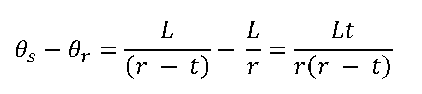 [0084] The length of the segment Ss of the sliding strip 12 that extends past the reference strip 14 can be found by dividing the angular extent in radians by 2 π to find the fraction of the circle and multiplying by the circumference.
 [0085] Solving these equations for the radius r gives:
 [0086] By measuring the relative shift between the strips, the radius of curvature across the length can be calculated using this simple equation. [0087] Now consider the case where bending occurs in a clockwise direction as shown in FIG.5.
[0088] The analysis proceeds much as before, but now the sliding strip 12 is on the outside, with a radius of curvature of
[0086] By measuring the relative shift between the strips, the radius of curvature across the length can be calculated using this simple equation. [0087] Now consider the case where bending occurs in a clockwise direction as shown in FIG.5.
[0088] The analysis proceeds much as before, but now the sliding strip 12 is on the outside, with a radius of curvature of

 [0089] As before, the goal is to locate the corresponding point 31 on the sliding strip 12 that corresponds to the endpoint of the reference strip 14. However, because the sliding strip 12 is on the outside and thus subtends a smaller angle the arc has to be continued to find the intersecting point. Ss is calculated by finding the angle subtended and the corresponding length on the sliding strip 12.
 [0090] This is the same result as obtained in the counterclockwise case. The difference here is that Ss in the first case is the amount the sliding strip 12 extended past the reference strip 14, and in this case, it is the amount extra that would be needed to reach the end of the reference strip 14. [0091] To combine these two cases, consider the radius of curvature to be a signed quantity, with a positive r indicating an arc which proceeds in a counterclockwise direction and a negative r indicating a clockwise direction. [0092] A new variable, Ls is defined as the total length along the sliding strip 12 to line up with the end of the reference strip 14. The signed radius of curvature is:
 [0093] In FIG. gave a positive radius of curvature.
 , gives
 a negative radius of curvature. The signed radius of curvature is then used to find the signed angular extent of the reference strip.
 Starting angle θ[ n ] is the tangent at the beginning of the arc. The ending angle is the tangent to the arc at its end, θ[ n + 1]. Similar to the calculation above,
 is the length of the reference strip 14 to measurement point
 is the length of the sliding strip 12 to measurement point n . On the side of the reference strip 14, the segment begins at
 and ends at
 Similarly, the corresponding sliding strip 12 extends from . The signed radius of curvature and the
 signed angular extent of the reference strip 14 segment can be found. [0098] We define the length of the reference strip 14 in segment n as:
 [0099] and the length of the corresponding sliding strip as:
 [0100] Similarly, we define the total subtended angle of this segment as:
 [0101] For the case of positive curvature and
 , the sliding strip
 12 is shaped into a tighter curve than the reference strip 14 Thus even
 though they subtend the same angle, Working in radians, the length of the
 reference segment is:
 [0102] and the length of the corresponding sliding segment is:
 [0103] Given the two lengths and the spacer thickness, we can solve for the radius of curvature of this segment:
 [0104] This same equation applies when the curve proceeds clockwise, giving a negative ending angle and negative radius of curvature. We can also solve for the subtended angle of the arc:
 [0105] A series of circular arcs of known length, angular extent, and radius of curvature is now known. This series can be pieced together to model the complete curve of the reference strip 14. It will be noted that, in an embodiment, multibend sensors have continuousflexure along their length and, thus, they are inherently continuous in their first derivative. Therefore, to maintain a continuousfirst derivative from segment to segment, the tangents of adjoining segments match. To put this another way, the ending angle of each segment matches the starting angle of the next segment. [0106] Consider a single arc as shown in FIG.7B. A starting angle and
 an ending angle which are tangent to the arc at its endpoints can be
 determined. It can be presumed that sequential segments connect smoothly – i.e., that the derivative is continuous at the point of connection. This is why the connection points are described by a single tangent angle. [0107] The arc begins at a known starting point
 and at an initial known angle 72 of
 and proceeds to an unknown ending point

 , at an unknown ending angle 7
 [0108] The change in angle from starting point to the ending point is just the turning of the segment angle,
 .To find the x, y translation, the increment in x and y over the arc is added to
of the arc is considered to be at the origin and used to calculate endpoint positions. The difference in these is then applied to the known starting point. [0109] For this calculation, the angles from the center that form the arc are known. The normal to For an arc of positive radius of curvature, this gives the
.To find the x, y translation, the increment in x and y over the arc is added to
of the arc is considered to be at the origin and used to calculate endpoint positions. The difference in these is then applied to the known starting point. [0109] For this calculation, the angles from the center that form the arc are known. The normal to For an arc of positive radius of curvature, this gives the
 angle pointing out from the center of the radius of curvature. If the radius of curvature is negative, it points in the opposite direction. This results in a sign flip that is corrected by using the signed radius of curvature. The endpoints can then be found iteratively via these equations:
 [0110] These equations can be slightly simplified using trig identities.
 [0111] These equations describe the series of circular arcs that model the bend. A circular arc is typically described by its center
 , its radius of curvature a starting angle, and an angular extent

 [0112] The center of an arc segment can be found by starting at
 , and following the radius to the arc center
 The starting angle is found from the normal at the point
 which is The center is then:

 [0113] Note that the use of the signed radius of curvature ensures following the normal to the center. [0114] The starting angle is:
 [0115] The sign is needed to flip the angle if the arc proceeds clockwise. The extent of the arc which is also a signed value.
 [0120] Ideal measurements for Lr [ n ] and Ls [ n ] are given. However, Ls [1] will be perturbed by a measurement error of δ. How this error propagates to
 is then found. [0121] In the unperturbed case (and noting that θ [0] = 0):

 [0122] Equally spaced measurement points, 1 unit apart are presumed.
 [0123] Apostrophes are used to indicate the variables for the case with measurement error
 This allows the resulting angles with and without mid-point measurement error to be.
 [0124] This shows that the ending angle after two arcs is unimpacted by a misreading in the middle point. The angle error does not propagate. [0125] The error in the point locations is considered.
 angle of segment 0:
 [0130] Next, wefind the ending angle of segment 1.
 the opposite side length (s) divided by the adjacent side length (t).
 [0137] And for the total length added:
 [0138] This formula is also correct for when the bend angle exceeds 180, and bends up towards the sliding strip 82. In this case the additional length is negative. [0139] For convenience, the bending angle, B, can be defined relative to no bend being 0.
 [0140] Substituting in:
 [0141] Given a measurement of shift, the angle that would have given rise to it is calculated.
 [0142] Like the circular arc model, this piecewise linear model still has the general behavior of measurement error in one shift measurement creating a complementary error in the next, partially canceling out the impact of potential additive error. [0143] Consider an ideal measurement vs one where there is measurement error in the first segment.

 [0144] The resulting angle of the last segment is simply the sum of the angle to that point.
 [0145] Repeating the calculation with measurement error: