WO2021205777A1 - プロセッサ装置及びその作動方法 - Google Patents
プロセッサ装置及びその作動方法 Download PDFInfo
- Publication number
- WO2021205777A1 WO2021205777A1 PCT/JP2021/007701 JP2021007701W WO2021205777A1 WO 2021205777 A1 WO2021205777 A1 WO 2021205777A1 JP 2021007701 W JP2021007701 W JP 2021007701W WO 2021205777 A1 WO2021205777 A1 WO 2021205777A1
- Authority
- WO
- WIPO (PCT)
- Prior art keywords
- display
- lesion information
- observation
- lesion
- image
- Prior art date
- Legal status (The legal status is an assumption and is not a legal conclusion. Google has not performed a legal analysis and makes no representation as to the accuracy of the status listed.)
- Ceased
Links
Images





Classifications
-
- A—HUMAN NECESSITIES
- A61—MEDICAL OR VETERINARY SCIENCE; HYGIENE
- A61B—DIAGNOSIS; SURGERY; IDENTIFICATION
- A61B1/00—Instruments for performing medical examinations of the interior of cavities or tubes of the body by visual or photographical inspection, e.g. endoscopes; Illuminating arrangements therefor
- A61B1/00002—Operational features of endoscopes
- A61B1/00004—Operational features of endoscopes characterised by electronic signal processing
- A61B1/00009—Operational features of endoscopes characterised by electronic signal processing of image signals during a use of endoscope
- A61B1/000094—Operational features of endoscopes characterised by electronic signal processing of image signals during a use of endoscope extracting biological structures
-
- A—HUMAN NECESSITIES
- A61—MEDICAL OR VETERINARY SCIENCE; HYGIENE
- A61B—DIAGNOSIS; SURGERY; IDENTIFICATION
- A61B1/00—Instruments for performing medical examinations of the interior of cavities or tubes of the body by visual or photographical inspection, e.g. endoscopes; Illuminating arrangements therefor
- A61B1/00002—Operational features of endoscopes
- A61B1/00004—Operational features of endoscopes characterised by electronic signal processing
- A61B1/00006—Operational features of endoscopes characterised by electronic signal processing of control signals
-
- A—HUMAN NECESSITIES
- A61—MEDICAL OR VETERINARY SCIENCE; HYGIENE
- A61B—DIAGNOSIS; SURGERY; IDENTIFICATION
- A61B1/00—Instruments for performing medical examinations of the interior of cavities or tubes of the body by visual or photographical inspection, e.g. endoscopes; Illuminating arrangements therefor
- A61B1/00002—Operational features of endoscopes
- A61B1/00043—Operational features of endoscopes provided with output arrangements
- A61B1/00045—Display arrangement
- A61B1/0005—Display arrangement combining images e.g. side-by-side, superimposed or tiled
-
- A—HUMAN NECESSITIES
- A61—MEDICAL OR VETERINARY SCIENCE; HYGIENE
- A61B—DIAGNOSIS; SURGERY; IDENTIFICATION
- A61B1/00—Instruments for performing medical examinations of the interior of cavities or tubes of the body by visual or photographical inspection, e.g. endoscopes; Illuminating arrangements therefor
- A61B1/04—Instruments for performing medical examinations of the interior of cavities or tubes of the body by visual or photographical inspection, e.g. endoscopes; Illuminating arrangements therefor combined with photographic or television appliances
- A61B1/045—Control thereof
-
- A—HUMAN NECESSITIES
- A61—MEDICAL OR VETERINARY SCIENCE; HYGIENE
- A61B—DIAGNOSIS; SURGERY; IDENTIFICATION
- A61B1/00—Instruments for performing medical examinations of the interior of cavities or tubes of the body by visual or photographical inspection, e.g. endoscopes; Illuminating arrangements therefor
- A61B1/06—Instruments for performing medical examinations of the interior of cavities or tubes of the body by visual or photographical inspection, e.g. endoscopes; Illuminating arrangements therefor with illuminating arrangements
-
- A—HUMAN NECESSITIES
- A61—MEDICAL OR VETERINARY SCIENCE; HYGIENE
- A61B—DIAGNOSIS; SURGERY; IDENTIFICATION
- A61B1/00—Instruments for performing medical examinations of the interior of cavities or tubes of the body by visual or photographical inspection, e.g. endoscopes; Illuminating arrangements therefor
- A61B1/06—Instruments for performing medical examinations of the interior of cavities or tubes of the body by visual or photographical inspection, e.g. endoscopes; Illuminating arrangements therefor with illuminating arrangements
- A61B1/0655—Control therefor
-
- G—PHYSICS
- G09—EDUCATION; CRYPTOGRAPHY; DISPLAY; ADVERTISING; SEALS
- G09G—ARRANGEMENTS OR CIRCUITS FOR CONTROL OF INDICATING DEVICES USING STATIC MEANS TO PRESENT VARIABLE INFORMATION
- G09G5/00—Control arrangements or circuits for visual indicators common to cathode-ray tube indicators and other visual indicators
-
- G—PHYSICS
- G09—EDUCATION; CRYPTOGRAPHY; DISPLAY; ADVERTISING; SEALS
- G09G—ARRANGEMENTS OR CIRCUITS FOR CONTROL OF INDICATING DEVICES USING STATIC MEANS TO PRESENT VARIABLE INFORMATION
- G09G5/00—Control arrangements or circuits for visual indicators common to cathode-ray tube indicators and other visual indicators
- G09G5/36—Control arrangements or circuits for visual indicators common to cathode-ray tube indicators and other visual indicators characterised by the display of a graphic pattern, e.g. using an all-points-addressable [APA] memory
-
- A—HUMAN NECESSITIES
- A61—MEDICAL OR VETERINARY SCIENCE; HYGIENE
- A61B—DIAGNOSIS; SURGERY; IDENTIFICATION
- A61B1/00—Instruments for performing medical examinations of the interior of cavities or tubes of the body by visual or photographical inspection, e.g. endoscopes; Illuminating arrangements therefor
- A61B1/00163—Optical arrangements
- A61B1/00186—Optical arrangements with imaging filters
-
- A—HUMAN NECESSITIES
- A61—MEDICAL OR VETERINARY SCIENCE; HYGIENE
- A61B—DIAGNOSIS; SURGERY; IDENTIFICATION
- A61B1/00—Instruments for performing medical examinations of the interior of cavities or tubes of the body by visual or photographical inspection, e.g. endoscopes; Illuminating arrangements therefor
- A61B1/00163—Optical arrangements
- A61B1/00188—Optical arrangements with focusing or zooming features
-
- A—HUMAN NECESSITIES
- A61—MEDICAL OR VETERINARY SCIENCE; HYGIENE
- A61B—DIAGNOSIS; SURGERY; IDENTIFICATION
- A61B1/00—Instruments for performing medical examinations of the interior of cavities or tubes of the body by visual or photographical inspection, e.g. endoscopes; Illuminating arrangements therefor
- A61B1/04—Instruments for performing medical examinations of the interior of cavities or tubes of the body by visual or photographical inspection, e.g. endoscopes; Illuminating arrangements therefor combined with photographic or television appliances
- A61B1/05—Instruments for performing medical examinations of the interior of cavities or tubes of the body by visual or photographical inspection, e.g. endoscopes; Illuminating arrangements therefor combined with photographic or television appliances characterised by the image sensor, e.g. camera, being in the distal end portion
-
- A—HUMAN NECESSITIES
- A61—MEDICAL OR VETERINARY SCIENCE; HYGIENE
- A61B—DIAGNOSIS; SURGERY; IDENTIFICATION
- A61B1/00—Instruments for performing medical examinations of the interior of cavities or tubes of the body by visual or photographical inspection, e.g. endoscopes; Illuminating arrangements therefor
- A61B1/06—Instruments for performing medical examinations of the interior of cavities or tubes of the body by visual or photographical inspection, e.g. endoscopes; Illuminating arrangements therefor with illuminating arrangements
- A61B1/0638—Instruments for performing medical examinations of the interior of cavities or tubes of the body by visual or photographical inspection, e.g. endoscopes; Illuminating arrangements therefor with illuminating arrangements providing two or more wavelengths
-
- A—HUMAN NECESSITIES
- A61—MEDICAL OR VETERINARY SCIENCE; HYGIENE
- A61B—DIAGNOSIS; SURGERY; IDENTIFICATION
- A61B1/00—Instruments for performing medical examinations of the interior of cavities or tubes of the body by visual or photographical inspection, e.g. endoscopes; Illuminating arrangements therefor
- A61B1/06—Instruments for performing medical examinations of the interior of cavities or tubes of the body by visual or photographical inspection, e.g. endoscopes; Illuminating arrangements therefor with illuminating arrangements
- A61B1/07—Instruments for performing medical examinations of the interior of cavities or tubes of the body by visual or photographical inspection, e.g. endoscopes; Illuminating arrangements therefor with illuminating arrangements using light-conductive means, e.g. optical fibres
-
- G—PHYSICS
- G09—EDUCATION; CRYPTOGRAPHY; DISPLAY; ADVERTISING; SEALS
- G09G—ARRANGEMENTS OR CIRCUITS FOR CONTROL OF INDICATING DEVICES USING STATIC MEANS TO PRESENT VARIABLE INFORMATION
- G09G2320/00—Control of display operating conditions
- G09G2320/02—Improving the quality of display appearance
- G09G2320/0247—Flicker reduction other than flicker reduction circuits used for single beam cathode-ray tubes
-
- G—PHYSICS
- G09—EDUCATION; CRYPTOGRAPHY; DISPLAY; ADVERTISING; SEALS
- G09G—ARRANGEMENTS OR CIRCUITS FOR CONTROL OF INDICATING DEVICES USING STATIC MEANS TO PRESENT VARIABLE INFORMATION
- G09G2340/00—Aspects of display data processing
- G09G2340/12—Overlay of images, i.e. displayed pixel being the result of switching between the corresponding input pixels
-
- G—PHYSICS
- G09—EDUCATION; CRYPTOGRAPHY; DISPLAY; ADVERTISING; SEALS
- G09G—ARRANGEMENTS OR CIRCUITS FOR CONTROL OF INDICATING DEVICES USING STATIC MEANS TO PRESENT VARIABLE INFORMATION
- G09G2380/00—Specific applications
- G09G2380/08—Biomedical applications
Definitions
- the present invention relates to a processor device that controls the display of lesion information such as the degree of certainty of a lesion on a display and a method of operating the processor.
- an endoscope system including a light source device, an endoscope, and a processor device.
- an observation object is irradiated with illumination light, and the observation object illuminated by the illumination light is imaged to acquire an endoscopic image as a medical image.
- the endoscopic image is displayed on the monitor and used for diagnosis.
- the user's diagnosis is supported by detecting and highlighting a region of interest such as a lesion region from an endoscopic image.
- a region of interest such as a lesion region from an endoscopic image.
- an alert image when a region of interest is detected, it is determined whether or not an alert image should be displayed based on the size of the region of interest, and the alert image may be displayed or hidden based on the determination result. It is shown.
- the alert image is displayed only when it is necessary to inform the user, such as when the size of the lesion is large.
- the endoscope When detecting a lesion or specifying a lesion range based on an endoscopic image as in Patent Document 1, the endoscope includes the distance to the observation target, the imaging angle, the brightness of the observation target, and the like.
- the non-lesion may be mistakenly detected as a lesion or the lesion may be overlooked. If there are too many false positives, it may cause flickering when the detection result is superimposed and displayed on the observation image, which may hinder the user's diagnosis.
- support such as lesion detection is not used in order to avoid erroneous detection, lesions may be overlooked. Therefore, it has been required to appropriately display lesion information according to observation conditions so that lesions are not overlooked while suppressing flicker due to erroneous detection or the like.
- An object of the present invention is to provide a processor device capable of appropriately displaying lesion information according to observation conditions and a method of operating the processor device.
- the image processing processor acquires and observes an observation condition including at least one moving speed of the endoscope, an observation distance between the endoscope and the observation target, or the brightness of the observation target.
- the lesion information obtained from the endoscopic image or the lesion information including at least one diagnostic purpose is acquired, and the lesion information on the display is obtained based on at least one of the observation conditions or the lesion information.
- the display format of is determined, and the display of lesion information is controlled according to the display format.
- the image processing processor may determine the display format when the moving speed is the first moving speed and the display format when the moving speed is the second moving speed slower than the first moving speed. preferable.
- the image processing processor hides the lesion information when the movement speed is at least the first movement speed or the brightness is less than the brightness threshold value. It is preferable to determine the display format.
- the image processing processor is preferably determined as a display format for displaying lesion information.
- the image processing processor determines a different display format for display depending on the certainty, and when the observation distance is the second observation distance shorter than the first observation distance. It is preferable to determine a different display format for display depending on the purpose of diagnosis.
- the image processing processor displays the lesion information on the display frame by frame as a display format for display.
- the display format for display is before and after the frame in which the certainty is less than the certainty threshold. It is preferable to specify a plurality of specific frames and determine a first display display format for displaying the lesion information based on the first arithmetic processing based on the lesion information of the plurality of specific frames. In the first display format, it is preferable to display the lesion information on the display when there are a specific number or more of the frames having a high degree of certainty among the plurality of specific frames.
- the image processing processor performs a second calculation based on the lesion information of a plurality of range diagnosis frames as a display format for display. Based on the processing, the display format for the second display for displaying the lesion information related to the diagnosis of the lesion range is determined, and when the observation distance is the second observation distance and the purpose of the diagnosis is the differential diagnosis, the display for display is used. As a format, it is preferable to determine a third display format for displaying the lesion information related to the differential diagnosis based on the third arithmetic processing based on the lesion information of the plurality of differential diagnosis frames.
- the lesion range based on the lesion information of a plurality of range diagnosis frames and display the lesion information using the lesion range.
- the discrimination content based on the lesion information of a plurality of differential diagnosis frames and display the lesion information using the differential content.
- the display image for displaying the lesion information is obtained based on the emission of the first illumination light
- the lesion information acquisition image for acquiring the lesion information is the second illumination having a different emission spectrum from the first illumination light. It is preferably obtained based on the emission of light.
- the image processing processor acquires an observation condition including at least one moving speed of the endoscope, an observation distance between the endoscope and the observation target, or the brightness of the observation target. Then, at the timing when the observation conditions are acquired, the lesion information obtained from the endoscopic image or the lesion information including at least one diagnostic purpose is acquired, and the display is performed based on at least one of the observation conditions or the lesion information.
- the display format of the lesion information in the above is determined, and the display of the lesion information on the display is controlled according to the display format.
- lesion information can be appropriately displayed according to observation conditions.
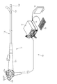
- the endoscope system 10 includes an endoscope 12, a light source device 14, a processor device 16, a display 18, and a user interface 19.
- the endoscope 12 is optically connected to the light source device 14 and electrically connected to the processor device 16.
- the endoscope 12 includes an insertion portion 12a to be inserted into the body to be observed, an operation portion 12b provided at the base end portion of the insertion portion 12a, and a curved portion 12c and a tip provided on the tip end side of the insertion portion 12a. It has a part 12d.
- the curved portion 12c bends by operating the angle knob 12e of the operating portion 12b.
- the tip portion 12d is directed in a desired direction by the bending motion of the bending portion 12c.
- the operation unit 12b includes a mode switching SW (mode switching switch) 12f used for mode switching operation, and a still image acquisition instruction unit 12g used for instructing acquisition of a still image to be observed.
- a zoom operation unit 12h used for operating the zoom lens 43 (see FIG. 2) is provided.
- the endoscope system 10 has three modes: a normal observation mode, a special observation mode, and a lesion information display mode.
- a normal observation image having a natural color is displayed on the display 18 by illuminating the observation target with normal light such as white light and taking an image.
- a special observation image emphasizing a specific structure is displayed on the display 18 by illuminating the observation target with special light having a wavelength band different from that of normal light and taking an image.
- the lesion information display mode the display format of the lesion information on the display 18 is determined based on at least one of the observation conditions and the lesion information, and the lesion information is displayed on the display 18 according to the determined display format.
- the lesion display mode in addition to continuously emitting either normal light or special light, the first illumination light and the second illumination light having different emission spectra are automatically switched to emit light in a specific emission pattern. You may.
- the still image acquisition instruction unit 12g When the user operates the still image acquisition instruction unit 12g, a signal related to the still image acquisition instruction is sent to the endoscope 12, the light source device 14, and the processor device 16.
- the still image acquisition instruction When the still image acquisition instruction is given, the still image to be observed is saved in the still image storage memory 69 (see FIG. 2) of the processor device 16.
- the processor device 16 is electrically connected to the display 18 and the user interface 19.
- the display 18 outputs and displays an image to be observed, information incidental to the image to be observed, and the like.
- the user interface 19 has a keyboard, a mouse, a touch pad, and the like, and has a function of accepting input operations such as function settings.
- An external recording unit (not shown) for recording an image, image information, or the like may be connected to the processor device 16.
- the light source device 14 includes a light source unit 20 and a light source processor 21 that controls the light source unit 20.
- the light source unit 20 emits illumination light for illuminating the observation target.
- the light source processor 21 controls the amount of illumination light emitted from the light source unit 20.
- the illumination light from the light source unit 20 is incident on the light guide 25 via the optical path coupling unit 23 composed of a mirror, a lens, or the like.
- the light guide 25 is built in the endoscope 12 and the universal cord (the cord connecting the endoscope 12, the light source device 14, and the processor device 16).
- the light guide 25 propagates the light from the optical path coupling portion 23 to the tip portion 12d of the endoscope 12.
- the tip portion 12d of the endoscope 12 is provided with an illumination optical system 30a and an imaging optical system 30b.
- the illumination optical system 30a has an illumination lens 32, and the illumination light propagated by the light guide 25 is applied to the observation target through the illumination lens 32.
- the image pickup optical system 30b has an objective lens 42 and an image pickup sensor 44. The light from the observation target due to the irradiation of the illumination light is incident on the image sensor 44 via the objective lens 42 and the zoom lens 43. As a result, an image to be observed is formed on the image sensor 44.
- the zoom lens 43 is a lens for enlarging the observation target, and moves between the telephoto end and the wide end by operating the zoom operation unit 12h.
- the image pickup sensor 44 is a primary color system color sensor, and is a B pixel (blue pixel) having a blue color filter, a G pixel (green pixel) having a green color filter, and an R pixel (red pixel) having a red color filter. It is provided with three types of pixels.
- the blue color filter BF mainly transmits light in the blue band, specifically, light in the wavelength band of 380 to 560 nm.
- the transmittance of the blue color filter BF peaks at a wavelength of around 460 to 470 nm.
- the green color filter transmits GF, mainly light in the green band, specifically, light in the wavelength band of 460 to 620 nm.
- the red color filter RF mainly transmits light in the red band, specifically, light in the wavelength band of 580 to 760 nm.
- the image sensor 44 is preferably a CCD (Charge-Coupled Device) or a CMOS (Complementary Metal Oxide Semiconductor).
- the imaging processor 45 controls the imaging sensor 44. Specifically, the image signal is output from the image sensor 44 by reading the signal of the image sensor 44 by the image processor 45.
- the CDS / AGC (Correlated Double Sampling / Automatic Gain Control) circuit 46 performs correlated double sampling (CDS) and automatic gain control (AGC) on the analog image signal obtained from the image sensor 44. ..
- CDS correlated double sampling
- AGC automatic gain control
- the image signal that has passed through the CDS / AGC circuit 46 is converted into a digital image signal by the A / D (Analog / Digital) converter 48.
- the digital image signal after A / D conversion is input to the processor device 16.
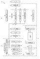
- the processor device 16 includes an image acquisition unit 50, a DSP (Digital Signal Processor) 52, a noise reduction unit 54, an image processing switching unit 56, an image processing unit 58, and a display control unit 60.
- the image processing unit 58 includes a normal observation image generation unit 62, a special observation image generation unit 64, and a lesion information processing unit 66.
- a program for performing various processes such as a process related to lesion information is stored in a program memory (not shown).
- the central control unit 68 composed of the image processing processor executes the program in the program memory
- the functions of the 56, the image processing unit 58, and the display control unit 60 are realized.
- the functions of the normal observation image generation unit 62, the special observation image generation unit 64, and the lesion information processing unit 66 included in the image processing unit 58 are realized.
- the lesion information processing unit 66 realizes the functions of the observation condition acquisition unit 70, the lesion information acquisition unit 72, and the display format determination unit 74 (see FIG. 4).
- the image acquisition unit 50 acquires an endoscope image input from the endoscope 12.
- the endoscopic image is a color composed of a blue signal (B image signal), a green signal (G image signal), and a red signal (R image signal) output from the B pixel, G pixel, and R pixel of the image sensor 44. It is preferably an image.
- the acquired color image is transmitted to the DSP 52.
- the DSP 52 performs various signal processing such as defect correction processing, offset processing, gain correction processing, matrix processing, gamma conversion processing, demosaic processing, and YC conversion processing on the received color image. In the defect correction process, the signal of the defective pixel of the image sensor 44 is corrected.
- the dark current component is removed from the image signal subjected to the defect correction processing, and an accurate zero level is set.
- the gain correction process adjusts the signal level of a color image by multiplying the image signal of each color after the offset process by a specific gain coefficient.
- the endoscope image may be imaged by the monochrome sensor for each emission of light of a specific color and may be a monochrome image of a plurality of colors output from the monochrome sensor. preferable.
- the image signal of each color after the gain correction processing is subjected to matrix processing to improve the color reproducibility. After that, the brightness and saturation of the color image are adjusted by the gamma conversion process.
- the color image after the matrix processing is subjected to demosaic processing (also referred to as isotropic processing or simultaneous processing), and a signal of the missing color of each pixel is generated by interpolation. By the demosaic process, all the pixels have signals of each color of RGB.
- the DSP 52 performs YC conversion processing on the color image after the demosaic processing, and outputs the luminance signal Y, the color difference signal Cb, and the color difference signal Cr to the noise reduction unit 54.
- the noise reduction unit 54 performs noise reduction processing by, for example, a moving average method or a median filter method on a color image that has undergone demosaic processing or the like by DSP 56.
- the color image with reduced noise is input to the image processing switching unit 56.
- the image processing switching unit 56 sets the transmission destination of the image signal from the noise reduction unit 54 to any of the normal observation image generation unit 62, the special observation image generation unit 64, and the lesion information processing unit 66. Switch to. Specifically, when the normal observation mode is set, the image signal from the noise reduction unit 54 is input to the normal observation image generation unit 62. When the special observation mode is set, the image signal from the noise reduction unit 54 is input to the special observation image generation unit 64. When the lesion information display mode is set, the image signal from the noise reduction unit 54 is input to the lesion information processing unit 66.
- the normal observation image generation unit 62 performs image processing for a normal observation image on the input endoscopic image.
- Image processing for normal observation images includes 3 ⁇ 3 matrix processing, gradation conversion processing, color conversion processing such as 3D LUT (Look Up Table) processing, color enhancement processing, and structure enhancement processing such as spatial frequency enhancement. Is done.
- the endoscopic image that has undergone image processing for a normal observation image is input to the display control unit 60 as a normal observation image.
- the special observation image generation unit 64 performs image processing for a special observation image on the input endoscopic image.
- Image processing for special observation images includes 3 ⁇ 3 matrix processing, gradation conversion processing, color conversion processing such as 3D LUT (Look Up Table) processing, color enhancement processing, and structure enhancement processing such as spatial frequency enhancement. Is done.
- the endoscopic image that has undergone image processing for a special observation image is input to the display control unit 60 as a special observation image.
- the lesion information processing unit 66 acquires observation conditions, extracts lesion information, and determines a display format of lesion information based on the input endoscopic image.
- the endoscopic image, the lesion information, and the display format of the lesion information are transmitted to the display control unit 60.
- the details of the lesion information processing unit 66 will be described later.
- the display control unit 60 controls to display the image or the like output from the image processing unit 58 on the display 18. Specifically, in the case of the normal observation mode or the special observation mode, the display control unit 60 converts the normal observation image or the special observation image into a video signal that can be displayed in full color on the display 18. The converted video signal is input to the display 18. As a result, the normal observation image or the special observation image is displayed on the display 18.
- the display control unit 60 can display the endoscopic image on the display 18 in full color, and can display the lesion information according to the display format of the lesion information on the display 18. Convert to a video signal. The converted video signal is input to the display 18. As a result, the display 18 displays an endoscopic image in which lesion information is superimposed and displayed.
- the lesion information processing unit 66 includes an observation condition acquisition unit 70, a lesion information acquisition unit 72, and a display format determination unit 74.
- the observation condition acquisition unit 70 acquires an observation condition including at least one of the moving speed of the endoscope 12, the observation distance between the endoscope 12 and the observation target, or the brightness of the observation target.
- the observation condition refers to other conditions including the shooting condition at the timing when the observation target is imaged by the user.
- the observation conditions include the moving speed of the tip portion 12d of the endoscope 12.
- the moving speed can be compared with the endoscopic images of several frames before or after the frame obtained at the timing of imaging (subblock limitation, simple block matching with limited search range), and the tip of the endoscope 12. It is acquired based on the movement information of the tip portion 12d obtained from the position information sensor (not shown) provided on the 12d.
- the movement speed it is used to determine whether the timing when the user is performing endoscopic observation is the timing when the lesion is detected or the timing when the user is simply moving to the target site. Be done.
- the frame is a unit of a period including at least a period from a specific timing to the completion of signal reading in the image sensor 44.
- the observation distance is preferably represented by, for example, the distance between the tip portion 12d of the endoscope 12 and the observation target.
- the zoom level at which the observation target is enlarged or reduced by operating the zoom operation unit 12h may be used.
- the zoom level is determined by the magnification of the observation target (no magnification, 25x, 50x, 75x, 125x, etc.).
- the observation distance may be determined by irradiating the observation target with the distance measuring laser light from the tip portion 12d of the endoscope 12 and using the distance information obtained based on the irradiation position of the distance measuring laser light on the observation target. good.
- observation distance distance information obtained from the area of the halation region (region where the brightness value is extremely high) generated by the illumination light emitted from the tip portion 12d of the endoscope 12 may be used.
- the observation distance is whether the timing of the user's endoscopic observation is the timing of the presence diagnosis to detect the presence of the lesion or the timing of the lesion range diagnosis to determine the extent of the lesion. , The stage of the lesion, etc. It is used to judge whether it is the timing to perform the differential diagnosis to distinguish the lesion.
- the brightness of the observation target may be the average value of the entire pixel values of the endoscopic image, and is based on the area of the dark region where the pixel values are equal to or less than a specific value in the effective pixel region of the endoscopic image. It may be a value obtained by The brightness of the observation target is used to determine whether or not the brightness is suitable for detecting a lesion or the like at the timing when the user is performing endoscopic observation.
- the lesion information acquisition unit 72 acquires the degree of certainty of the lesion obtained from the endoscopic image or the lesion information including at least the purpose of diagnosis at the timing when the observation conditions are acquired.
- the degree of certainty of the lesion is preferably calculated by performing AI (Artificial Intelligence) processing on the endoscopic image.
- the degree of certainty of the lesion is preferably expressed by a numerical value such as "60" or "80". It is preferable to use CNN (Convolutional Neural Network) as the AI treatment.
- the diagnostic purpose is preferably entered by the user via the user interface 19.
- the purpose of diagnosis includes presence diagnosis for detecting the presence of a lesion, lesion range diagnosis for determining the extent of a lesion, and differential diagnosis for differentiating a lesion such as a stage of a lesion.
- blood vessel information is extracted from endoscopic images, and features such as blood vessel density and density distribution, blood vessel thickness fluctuation and fluctuation distribution, blood vessel diameter distribution and presence / absence of bleeding, and blood vessel and surface structure by AI.
- the information may be obtained based on regularity, complexity, and the like.
- the display format determination unit 74 determines the display format of the lesion information on the display 18 based on at least one of the observation conditions and the lesion information.
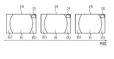
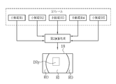
- a display format of the lesion information as shown in FIG. 5, RI in the observation image display area for displaying the endoscopic image, or an observation image for displaying information other than the endoscopic image outside the observation image display area.
- Each of the ROs outside the display area has a non-display display format that hides the lesion information.
- RI in the observation image display area for displaying the endoscopic image or information other than the endoscopic image is displayed outside the observation image display area.
- At least one of the ROs outside the observation image display area has a display format for displaying the lesion information DI.
- the display format determining unit 74 determines the display format when the moving speed is the first moving speed and the display format when the moving speed is the second moving speed slower than the first moving speed.
- the first moving speed is a high speed at which the speed threshold value exceeds a certain value
- the situation where the tip portion 12d of the endoscope is moved at the first moving speed is the situation where the tip portion 12d of the endoscope is moved to the target observation site. Therefore, it is considered that the purpose is not to obtain lesion information. Therefore, when the movement speed is the first movement speed, the display format determination unit 74 determines the display format of the lesion information as the non-display display format.
- the display format determination unit 74 determines the display format of the lesion information as the non-display display format even when the brightness of the observation target is less than the brightness threshold value.
- the display format determining unit 74 determines the display format of the lesion information as the display format for display. ..
- the second moving speed is a slow speed at which the speed threshold value is less than a certain value, and it is considered that the situation where the tip portion 12d of the endoscope is moved at the second moving speed is for the purpose of acquiring lesion information. Be done.
- the type of the lesion information to be acquired is often different depending on the observation distance. Therefore, it is preferable to use a different display format for display depending on the observation distance.
- the display format determination unit 74 determines a different display format for display according to the certainty of the lesion, and the observation distance is larger than the first observation distance.
- the second observation distance is short, a different display format for display is determined according to the purpose of diagnosis.
- the first observation distance is preferably the distance of distant view observation performed under a situation such as screening.
- the second observation distance is preferably a near view distance performed under circumstances such as lesion range diagnosis and differential diagnosis.
- the display format determination unit 74 displays the lesion information for each frame as the display format for display 18 It is preferable to determine the format to be displayed in.
- the certainty of the lesion which is one of the lesion information DIs, is continuously displayed for each frame.
- the certainty may be displayed graphically in the RO outside the observation image area.
- lesion information may be displayed on the RI in the observation image area. For example, the lesion information may be visualized and overlaid on the observation image according to the user's instruction.
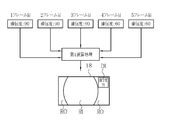
- the display format for display when the certainty of the lesion is less than the certainty threshold at the first observation distance, a plurality of specific frames before and after the frame whose certainty is less than the certainty threshold are specified as the display format for display. It is preferable to determine the first display format for displaying the lesion information on the display 18 based on the first arithmetic processing based on the lesion information of a plurality of specific frames. Specifically, in the first display format, it is preferable to display the lesion information on the display 18 when there are a specific number or more of the plurality of frames whose certainty is a certain value or more. This is because when the certainty of the lesion is less than the threshold for the certainty, the display of the lesion information is displayed in order to prevent the lesion from being overlooked while suppressing the flicker caused by the continuous display of the lesion information. This is to avoid not being done.
- the certainty of the lesion at the 5th frame is "60" below a certain value (for example, "80"), from the 5th frame and the 5th frame.
- the previous 1st to 4th frames are specified as a plurality of specific frames.
- the specific number which is the criterion for determining whether to display lesion information
- the certainty of the 1st to 3rd frames out of the 1st to 5th frames is a certain value of "80" or more. Therefore, the number of frames whose certainty is above a certain value is a specific number of "3 frames" or more.
- the lesion information is displayed on the display 18 based on the first arithmetic processing based on the lesion information in the 1st to 5th frames.
- the content of the lesion information is obtained by performing, for example, a process of calculating a representative value (average value, maximum value) of the certainty of the 1st to 5th frames as the first calculation process.
- “78” which is the average value of the certainty of the 1st to 5th frames, is displayed as the lesion information DI in the RO outside the observation image area.
- the lesion information may be displayed as a graph in addition to the numerical information.
- lesion information may be displayed on the RI in the observation image area. For example, the lesion information may be visualized and overlaid on the observation image according to the user's instruction.
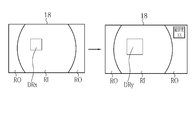
- the display format determination unit 74 uses the display format for display as a second display format based on the lesion information of a plurality of range diagnosis frames. Based on the arithmetic processing, the display format for the second display for displaying the lesion information related to the lesion range diagnosis on the display 18 is determined. In the second display format, it is preferable that the lesion range is determined based on the lesion information of the plurality of range diagnostic frames, and the lesion information is displayed on the display 18 using the lesion range.
- the lesion information acquisition unit 72 calculates the certainty of the lesion for each pixel or small area of the endoscopic image, and the certainty is the pixel of the threshold for range or
- the lesion area DRx is set by integrating the small areas.
- the display format determination unit 74 intends to display the lesion information related to the lesion range as the lesion information when the plurality of range diagnosis frames are defined as 5 frames, as shown in FIG.
- the average value of the certainty of the small areas SR1 to SR5 for 5 frames is calculated, and the small areas whose average value is equal to or larger than the range threshold are integrated to obtain the lesion range for resetting.
- the lesion range DRx before resetting is reset to the lesion range DRy for resetting.
- overlay display is performed on the RI in the observation image area so that the portion corresponding to the lesion area for resetting is emphasized.
- the small area is preferably an area in which the pixels in the vertical direction are a plurality of pixels and the pixels in the vertical direction are a plurality of pixels. Further, the certainty level may not be displayed on the RO outside the observation image area. Further, it is preferable to display the lesion information using the lesion range in a cycle of a plurality of range diagnosis frames.
- the display format determination unit 74 uses the display format for the display as a third calculation based on the lesion information of a plurality of differential diagnosis frames. Based on the process, a third display format for displaying the lesion information related to the differential diagnosis on the display 18 is determined. In the third display format, the differential content is determined based on the lesion information of the plurality of differential diagnosis frames, and the lesion information is displayed on the display 18 using the differential content.
- the lesion information acquisition unit 72 integrates the pixels of the endoscopic image and the features of each small area, and is convinced that the severity and stage of the lesion area are determined for each frame. Determine the degree.
- stage and certainty of the lesion area for example, in the case of Barrett's esophagus, there are stages of "bullet without dysplasia”, “severe dysplasia”, and “adenocarcinoma”, and the certainty is “adenocarcinoma: 60". It is expressed as.
- colorectal cancer there are stages of "benign polyp", “adenocarcinoma”, and “adenocarcinoma”, and the certainty is expressed as "benign polyp: 80".
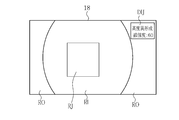
- the display format determination unit 74 performs stage determination results JD1 to JD5 for 5 frames as the third arithmetic processing as shown in FIG.
- the final stage discrimination result JDf and the certainty PBf are calculated based on the certainty PB1 to PB5, and the final stage discrimination result JDf and the certainty PBf are displayed on the display 18 as lesion information using the differential diagnosis. do.
- the differential diagnosis is Barrett's esophageal differentiation
- 4 of the 5 frames of stage discrimination results are "severe dysplasia”
- “severe dysplasia” is the final stage discrimination result.
- the representative value (average value, etc.) “60” of the certainty of the four frames for which “high degree dysplasia” is determined is defined as the final certainty PBf.
- the region RJ included in the specific range of the final certainty degree “60” is highlighted in the RI in the observation image region, and the observation image is displayed.
- High degree dysplasia, certainty: 60 is displayed on the RO outside the area.
- the degree of certainty may be displayed as a graph. Further, the certainty level may not be displayed on the RO outside the observation image area.
- the observation information includes at least one of the moving speed of the endoscope 12, the observation distance between the endoscope 12 and the observation target, or the brightness of the observation target.
- Lesion information includes the certainty of the lesion obtained from the endoscopic image, or at least one for diagnostic purposes.
- the display format determination unit 74 determines the display format of the lesion information on the display 18 based on at least one of the observation conditions and the lesion information.
- the display control unit 60 displays the lesion information on the display 18 according to the display format determined by the display format determination unit 74.
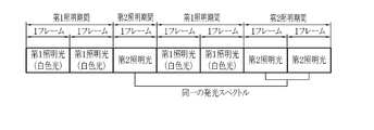
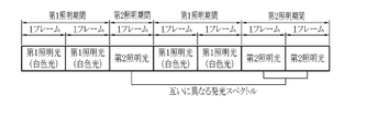
- the lesion information display mode when the first illumination light and the second illumination light having different emission spectra are automatically switched to emit light, the first illumination light is emitted in the first emission pattern and the second illumination is emitted. Light is emitted in the second emission pattern.
- a display image for displaying lesion information can be acquired based on the emission of the first illumination light.
- the image for acquiring the lesion information for acquiring the lesion information can be acquired based on the emission of the second illumination light.
- the first light emission pattern includes the first A light emission pattern in which the number of frames in the first lighting period for emitting the first illumination light is the same in each first illumination period.
- the number of frames in the first illumination period is one of the first B emission patterns different in each first illumination period.
- the second illumination period indicates the period for emitting the second illumination light. The period is represented by the number of frames.
- the number of frames in the second illumination period is the same in each second illumination period, and the emission spectrum of the second illumination light is in each second illumination period.
- the number of frames in the second illumination period is the same in each of the second illumination periods, and the emission spectrum of the second illumination light is the same in each second illumination period.
- Second B pattern different in the illumination period as shown in FIG. 17, the number of frames in the second illumination period is different in each second illumination period, and the emission spectrum of the second illumination light is different.
- the second C pattern which is the same in the second illumination period, as shown in FIG. 18, the number of frames in the second illumination period is different in each second illumination period, and the emission spectrum of the second illumination light is different. It is preferably one of the second D patterns that are different in each second illumination period.
- the emission spectrum of the first illumination light may be the same or different in each first illumination period.
- the first lighting period is preferably longer than the second lighting period, and the first lighting period is preferably two frames or more.
- the first lighting period is set to 2 frames
- the second lighting period is set to 1 frame. Since the first illumination light is used to generate a display image to be displayed on the display 18, it is preferable to obtain a bright image by illuminating the observation target with the first illumination light.
- the first illumination light is preferably white light.
- the second illumination light is used for acquiring the lesion information, it is preferable to illuminate the observation target with the second illumination light to obtain an image suitable for acquiring the lesion information.
- the second illumination light is preferably short-wavelength narrow-band light such as purple light.
- the display format of the lesion information is determined in real time based on the observation condition or the lesion information, but in consideration of the real-time property, the display format of the lesion information is determined in advance for each observation condition or the lesion information.
- the display format corresponding to the acquired observation condition or lesion information may be selected from the predetermined display formats.
- Hardware-like processing unit that executes various processes such as generation unit 64, lesion information processing unit 66, central control unit 68, observation condition acquisition unit 70, lesion information acquisition unit 72, and display format determination unit 74.
- the structure is various processors as shown below.
- the circuit configuration is changed after manufacturing the CPU (Central Processing Unit), FPGA (Field Programmable Gate Array), etc., which are general-purpose processors that execute software (programs) and function as various processing units. It includes a programmable logic device (PLD), which is a possible processor, a dedicated electric circuit, which is a processor having a circuit configuration specially designed for executing various processes, and the like.
- PLD programmable logic device
- One processing unit may be composed of one of these various processors, or may be composed of a combination of two or more processors of the same type or different types (for example, a plurality of FPGAs or a combination of a CPU and an FPGA). May be done. Further, a plurality of processing units may be configured by one processor. As an example of configuring a plurality of processing units with one processor, first, as represented by a computer such as a client or a server, one processor is configured by a combination of one or more CPUs and software. There is a form in which this processor functions as a plurality of processing units.
- SoC System On Chip
- a processor that realizes the functions of the entire system including a plurality of processing units with one IC (Integrated Circuit) chip is used.
- the various processing units are configured by using one or more of the above-mentioned various processors as a hardware-like structure.
- the hardware structure of these various processors is, more specifically, an electric circuit (circuitry) in which circuit elements such as semiconductor elements are combined.
- the hardware structure of the storage unit is a storage device such as an HDD (hard disk drive) or SSD (solid state drive).
Landscapes
- Health & Medical Sciences (AREA)
- Life Sciences & Earth Sciences (AREA)
- Surgery (AREA)
- Engineering & Computer Science (AREA)
- Physics & Mathematics (AREA)
- Biophysics (AREA)
- Veterinary Medicine (AREA)
- Optics & Photonics (AREA)
- Pathology (AREA)
- Radiology & Medical Imaging (AREA)
- Nuclear Medicine, Radiotherapy & Molecular Imaging (AREA)
- Biomedical Technology (AREA)
- Heart & Thoracic Surgery (AREA)
- Medical Informatics (AREA)
- Molecular Biology (AREA)
- Animal Behavior & Ethology (AREA)
- General Health & Medical Sciences (AREA)
- Public Health (AREA)
- Signal Processing (AREA)
- Computer Hardware Design (AREA)
- General Physics & Mathematics (AREA)
- Theoretical Computer Science (AREA)
- Endoscopes (AREA)
Priority Applications (3)
| Application Number | Priority Date | Filing Date | Title |
|---|---|---|---|
| CN202180027174.5A CN115397303A (zh) | 2020-04-08 | 2021-03-01 | 处理器装置及其工作方法 |
| JP2022514334A JP7447243B2 (ja) | 2020-04-08 | 2021-03-01 | プロセッサ装置及びその作動方法 |
| US17/938,617 US20230030057A1 (en) | 2020-04-08 | 2022-10-06 | Processor device and method of operating the same |
Applications Claiming Priority (2)
| Application Number | Priority Date | Filing Date | Title |
|---|---|---|---|
| JP2020-069713 | 2020-04-08 | ||
| JP2020069713 | 2020-04-08 |
Related Child Applications (1)
| Application Number | Title | Priority Date | Filing Date |
|---|---|---|---|
| US17/938,617 Continuation US20230030057A1 (en) | 2020-04-08 | 2022-10-06 | Processor device and method of operating the same |
Publications (1)
| Publication Number | Publication Date |
|---|---|
| WO2021205777A1 true WO2021205777A1 (ja) | 2021-10-14 |
Family
ID=78023307
Family Applications (1)
| Application Number | Title | Priority Date | Filing Date |
|---|---|---|---|
| PCT/JP2021/007701 Ceased WO2021205777A1 (ja) | 2020-04-08 | 2021-03-01 | プロセッサ装置及びその作動方法 |
Country Status (4)
| Country | Link |
|---|---|
| US (1) | US20230030057A1 (https=) |
| JP (1) | JP7447243B2 (https=) |
| CN (1) | CN115397303A (https=) |
| WO (1) | WO2021205777A1 (https=) |
Families Citing this family (1)
| Publication number | Priority date | Publication date | Assignee | Title |
|---|---|---|---|---|
| WO2022120212A1 (en) * | 2020-12-04 | 2022-06-09 | Board Of Regents Of The Nevada System Of Higher Education, On Behalf Of The University Of Nevada, Reno | Apparatus and method for detecting cervical cancer |
Citations (5)
| Publication number | Priority date | Publication date | Assignee | Title |
|---|---|---|---|---|
| WO2018105063A1 (ja) * | 2016-12-07 | 2018-06-14 | オリンパス株式会社 | 画像処理装置 |
| WO2018159461A1 (ja) * | 2017-03-03 | 2018-09-07 | 富士フイルム株式会社 | 内視鏡システム、プロセッサ装置、及び、内視鏡システムの作動方法 |
| WO2019059059A1 (ja) * | 2017-09-22 | 2019-03-28 | 富士フイルム株式会社 | 医療画像処理システム、内視鏡システム、診断支援装置、並びに医療業務支援装置 |
| WO2019065111A1 (ja) * | 2017-09-26 | 2019-04-04 | 富士フイルム株式会社 | 医療画像処理システム、内視鏡システム、診断支援装置、及び医療業務支援装置 |
| WO2019088121A1 (ja) * | 2017-10-30 | 2019-05-09 | 公益財団法人がん研究会 | 画像診断支援装置、資料収集方法、画像診断支援方法および画像診断支援プログラム |
Family Cites Families (2)
| Publication number | Priority date | Publication date | Assignee | Title |
|---|---|---|---|---|
| JP6192882B1 (ja) * | 2015-10-08 | 2017-09-06 | オリンパス株式会社 | 内視鏡システム |
| CN110461209B (zh) * | 2017-03-30 | 2021-10-29 | 富士胶片株式会社 | 内窥镜系统及处理器装置 |
-
2021
- 2021-03-01 WO PCT/JP2021/007701 patent/WO2021205777A1/ja not_active Ceased
- 2021-03-01 CN CN202180027174.5A patent/CN115397303A/zh active Pending
- 2021-03-01 JP JP2022514334A patent/JP7447243B2/ja active Active
-
2022
- 2022-10-06 US US17/938,617 patent/US20230030057A1/en not_active Abandoned
Patent Citations (5)
| Publication number | Priority date | Publication date | Assignee | Title |
|---|---|---|---|---|
| WO2018105063A1 (ja) * | 2016-12-07 | 2018-06-14 | オリンパス株式会社 | 画像処理装置 |
| WO2018159461A1 (ja) * | 2017-03-03 | 2018-09-07 | 富士フイルム株式会社 | 内視鏡システム、プロセッサ装置、及び、内視鏡システムの作動方法 |
| WO2019059059A1 (ja) * | 2017-09-22 | 2019-03-28 | 富士フイルム株式会社 | 医療画像処理システム、内視鏡システム、診断支援装置、並びに医療業務支援装置 |
| WO2019065111A1 (ja) * | 2017-09-26 | 2019-04-04 | 富士フイルム株式会社 | 医療画像処理システム、内視鏡システム、診断支援装置、及び医療業務支援装置 |
| WO2019088121A1 (ja) * | 2017-10-30 | 2019-05-09 | 公益財団法人がん研究会 | 画像診断支援装置、資料収集方法、画像診断支援方法および画像診断支援プログラム |
Also Published As
| Publication number | Publication date |
|---|---|
| JP7447243B2 (ja) | 2024-03-11 |
| JPWO2021205777A1 (https=) | 2021-10-14 |
| US20230030057A1 (en) | 2023-02-02 |
| CN115397303A (zh) | 2022-11-25 |
Similar Documents
| Publication | Publication Date | Title |
|---|---|---|
| JP6785941B2 (ja) | 内視鏡システム及びその作動方法 | |
| JP7542585B2 (ja) | 画像処理装置、内視鏡システム及び画像処理装置の作動方法 | |
| JP6858672B2 (ja) | 医療画像処理システム及び内視鏡システム | |
| JP6924837B2 (ja) | 医療画像処理システム、内視鏡システム、診断支援装置、並びに医療業務支援装置 | |
| JP7047122B2 (ja) | 医用画像処理装置及び内視鏡システム並びに医用画像処理装置の作動方法 | |
| JP7402314B2 (ja) | 医用画像処理システム、医用画像処理システムの作動方法 | |
| JP7335399B2 (ja) | 医用画像処理装置及び内視鏡システム並びに医用画像処理装置の作動方法 | |
| JPWO2020054255A1 (ja) | 内視鏡装置、内視鏡プロセッサ、及び内視鏡装置の操作方法 | |
| US20190246874A1 (en) | Processor device, endoscope system, and method of operating processor device | |
| US20230027950A1 (en) | Medical image processing apparatus, endoscope system, method of operating medical image processing apparatus, and non-transitory computer readable medium | |
| US12051201B2 (en) | Image processing device capable of accurately determining ulcerative colitis by using a medical image and method of operating the same | |
| JP2020065685A (ja) | 内視鏡システム | |
| JP7130043B2 (ja) | 医用画像処理装置及び内視鏡システム並びに医用画像処理装置の作動方法 | |
| US12254626B2 (en) | Image processing device, endoscope system, and image processing method | |
| JP7637683B2 (ja) | プロセッサ装置、プロセッサ装置の作動方法 | |
| JP7447243B2 (ja) | プロセッサ装置及びその作動方法 | |
| JP7556960B2 (ja) | 内視鏡システム及びその作動方法 | |
| JP7593796B2 (ja) | 医用画像処理システム、医用画像処理システムの作動方法 | |
| JP7411515B2 (ja) | 内視鏡システム及びその作動方法 | |
| JP6196599B2 (ja) | 内視鏡用のプロセッサ装置、内視鏡用のプロセッサ装置の作動方法 | |
| WO2022059233A1 (ja) | 画像処理装置、内視鏡システム、画像処理装置の作動方法、及び画像処理装置用プログラム |
Legal Events
| Date | Code | Title | Description |
|---|---|---|---|
| 121 | Ep: the epo has been informed by wipo that ep was designated in this application |
Ref document number: 21784841 Country of ref document: EP Kind code of ref document: A1 |
|
| ENP | Entry into the national phase |
Ref document number: 2022514334 Country of ref document: JP Kind code of ref document: A |
|
| NENP | Non-entry into the national phase |
Ref country code: DE |
|
| 122 | Ep: pct application non-entry in european phase |
Ref document number: 21784841 Country of ref document: EP Kind code of ref document: A1 |