WO2021205710A1 - Motor control device, electric vehicle, and motor control method - Google Patents
Motor control device, electric vehicle, and motor control method Download PDFInfo
- Publication number
- WO2021205710A1 WO2021205710A1 PCT/JP2021/002146 JP2021002146W WO2021205710A1 WO 2021205710 A1 WO2021205710 A1 WO 2021205710A1 JP 2021002146 W JP2021002146 W JP 2021002146W WO 2021205710 A1 WO2021205710 A1 WO 2021205710A1
- Authority
- WO
- WIPO (PCT)
- Prior art keywords
- motor
- inverter circuit
- pulsation
- electromagnetic force
- carrier signal
- Prior art date
Links
Images


Classifications
-
- H—ELECTRICITY
- H02—GENERATION; CONVERSION OR DISTRIBUTION OF ELECTRIC POWER
- H02M—APPARATUS FOR CONVERSION BETWEEN AC AND AC, BETWEEN AC AND DC, OR BETWEEN DC AND DC, AND FOR USE WITH MAINS OR SIMILAR POWER SUPPLY SYSTEMS; CONVERSION OF DC OR AC INPUT POWER INTO SURGE OUTPUT POWER; CONTROL OR REGULATION THEREOF
- H02M7/00—Conversion of ac power input into dc power output; Conversion of dc power input into ac power output
- H02M7/42—Conversion of dc power input into ac power output without possibility of reversal
- H02M7/44—Conversion of dc power input into ac power output without possibility of reversal by static converters
- H02M7/48—Conversion of dc power input into ac power output without possibility of reversal by static converters using discharge tubes with control electrode or semiconductor devices with control electrode
- H02M7/53—Conversion of dc power input into ac power output without possibility of reversal by static converters using discharge tubes with control electrode or semiconductor devices with control electrode using devices of a triode or transistor type requiring continuous application of a control signal
- H02M7/537—Conversion of dc power input into ac power output without possibility of reversal by static converters using discharge tubes with control electrode or semiconductor devices with control electrode using devices of a triode or transistor type requiring continuous application of a control signal using semiconductor devices only, e.g. single switched pulse inverters
- H02M7/5387—Conversion of dc power input into ac power output without possibility of reversal by static converters using discharge tubes with control electrode or semiconductor devices with control electrode using devices of a triode or transistor type requiring continuous application of a control signal using semiconductor devices only, e.g. single switched pulse inverters in a bridge configuration
- H02M7/53871—Conversion of dc power input into ac power output without possibility of reversal by static converters using discharge tubes with control electrode or semiconductor devices with control electrode using devices of a triode or transistor type requiring continuous application of a control signal using semiconductor devices only, e.g. single switched pulse inverters in a bridge configuration with automatic control of output voltage or current
-
- H—ELECTRICITY
- H02—GENERATION; CONVERSION OR DISTRIBUTION OF ELECTRIC POWER
- H02P—CONTROL OR REGULATION OF ELECTRIC MOTORS, ELECTRIC GENERATORS OR DYNAMO-ELECTRIC CONVERTERS; CONTROLLING TRANSFORMERS, REACTORS OR CHOKE COILS
- H02P27/00—Arrangements or methods for the control of AC motors characterised by the kind of supply voltage
- H02P27/04—Arrangements or methods for the control of AC motors characterised by the kind of supply voltage using variable-frequency supply voltage, e.g. inverter or converter supply voltage
- H02P27/06—Arrangements or methods for the control of AC motors characterised by the kind of supply voltage using variable-frequency supply voltage, e.g. inverter or converter supply voltage using dc to ac converters or inverters
- H02P27/08—Arrangements or methods for the control of AC motors characterised by the kind of supply voltage using variable-frequency supply voltage, e.g. inverter or converter supply voltage using dc to ac converters or inverters with pulse width modulation
-
- B—PERFORMING OPERATIONS; TRANSPORTING
- B60—VEHICLES IN GENERAL
- B60L—PROPULSION OF ELECTRICALLY-PROPELLED VEHICLES; SUPPLYING ELECTRIC POWER FOR AUXILIARY EQUIPMENT OF ELECTRICALLY-PROPELLED VEHICLES; ELECTRODYNAMIC BRAKE SYSTEMS FOR VEHICLES IN GENERAL; MAGNETIC SUSPENSION OR LEVITATION FOR VEHICLES; MONITORING OPERATING VARIABLES OF ELECTRICALLY-PROPELLED VEHICLES; ELECTRIC SAFETY DEVICES FOR ELECTRICALLY-PROPELLED VEHICLES
- B60L15/00—Methods, circuits, or devices for controlling the traction-motor speed of electrically-propelled vehicles
- B60L15/02—Methods, circuits, or devices for controlling the traction-motor speed of electrically-propelled vehicles characterised by the form of the current used in the control circuit
- B60L15/025—Methods, circuits, or devices for controlling the traction-motor speed of electrically-propelled vehicles characterised by the form of the current used in the control circuit using field orientation; Vector control; Direct Torque Control [DTC]
-
- B—PERFORMING OPERATIONS; TRANSPORTING
- B60—VEHICLES IN GENERAL
- B60L—PROPULSION OF ELECTRICALLY-PROPELLED VEHICLES; SUPPLYING ELECTRIC POWER FOR AUXILIARY EQUIPMENT OF ELECTRICALLY-PROPELLED VEHICLES; ELECTRODYNAMIC BRAKE SYSTEMS FOR VEHICLES IN GENERAL; MAGNETIC SUSPENSION OR LEVITATION FOR VEHICLES; MONITORING OPERATING VARIABLES OF ELECTRICALLY-PROPELLED VEHICLES; ELECTRIC SAFETY DEVICES FOR ELECTRICALLY-PROPELLED VEHICLES
- B60L3/00—Electric devices on electrically-propelled vehicles for safety purposes; Monitoring operating variables, e.g. speed, deceleration or energy consumption
- B60L3/0092—Electric devices on electrically-propelled vehicles for safety purposes; Monitoring operating variables, e.g. speed, deceleration or energy consumption with use of redundant elements for safety purposes
-
- B—PERFORMING OPERATIONS; TRANSPORTING
- B60—VEHICLES IN GENERAL
- B60L—PROPULSION OF ELECTRICALLY-PROPELLED VEHICLES; SUPPLYING ELECTRIC POWER FOR AUXILIARY EQUIPMENT OF ELECTRICALLY-PROPELLED VEHICLES; ELECTRODYNAMIC BRAKE SYSTEMS FOR VEHICLES IN GENERAL; MAGNETIC SUSPENSION OR LEVITATION FOR VEHICLES; MONITORING OPERATING VARIABLES OF ELECTRICALLY-PROPELLED VEHICLES; ELECTRIC SAFETY DEVICES FOR ELECTRICALLY-PROPELLED VEHICLES
- B60L50/00—Electric propulsion with power supplied within the vehicle
- B60L50/50—Electric propulsion with power supplied within the vehicle using propulsion power supplied by batteries or fuel cells
- B60L50/51—Electric propulsion with power supplied within the vehicle using propulsion power supplied by batteries or fuel cells characterised by AC-motors
-
- H—ELECTRICITY
- H02—GENERATION; CONVERSION OR DISTRIBUTION OF ELECTRIC POWER
- H02M—APPARATUS FOR CONVERSION BETWEEN AC AND AC, BETWEEN AC AND DC, OR BETWEEN DC AND DC, AND FOR USE WITH MAINS OR SIMILAR POWER SUPPLY SYSTEMS; CONVERSION OF DC OR AC INPUT POWER INTO SURGE OUTPUT POWER; CONTROL OR REGULATION THEREOF
- H02M7/00—Conversion of ac power input into dc power output; Conversion of dc power input into ac power output
- H02M7/42—Conversion of dc power input into ac power output without possibility of reversal
- H02M7/44—Conversion of dc power input into ac power output without possibility of reversal by static converters
- H02M7/48—Conversion of dc power input into ac power output without possibility of reversal by static converters using discharge tubes with control electrode or semiconductor devices with control electrode
- H02M7/493—Conversion of dc power input into ac power output without possibility of reversal by static converters using discharge tubes with control electrode or semiconductor devices with control electrode the static converters being arranged for operation in parallel
-
- H—ELECTRICITY
- H02—GENERATION; CONVERSION OR DISTRIBUTION OF ELECTRIC POWER
- H02M—APPARATUS FOR CONVERSION BETWEEN AC AND AC, BETWEEN AC AND DC, OR BETWEEN DC AND DC, AND FOR USE WITH MAINS OR SIMILAR POWER SUPPLY SYSTEMS; CONVERSION OF DC OR AC INPUT POWER INTO SURGE OUTPUT POWER; CONTROL OR REGULATION THEREOF
- H02M7/00—Conversion of ac power input into dc power output; Conversion of dc power input into ac power output
- H02M7/42—Conversion of dc power input into ac power output without possibility of reversal
- H02M7/44—Conversion of dc power input into ac power output without possibility of reversal by static converters
- H02M7/48—Conversion of dc power input into ac power output without possibility of reversal by static converters using discharge tubes with control electrode or semiconductor devices with control electrode
- H02M7/53—Conversion of dc power input into ac power output without possibility of reversal by static converters using discharge tubes with control electrode or semiconductor devices with control electrode using devices of a triode or transistor type requiring continuous application of a control signal
- H02M7/537—Conversion of dc power input into ac power output without possibility of reversal by static converters using discharge tubes with control electrode or semiconductor devices with control electrode using devices of a triode or transistor type requiring continuous application of a control signal using semiconductor devices only, e.g. single switched pulse inverters
- H02M7/539—Conversion of dc power input into ac power output without possibility of reversal by static converters using discharge tubes with control electrode or semiconductor devices with control electrode using devices of a triode or transistor type requiring continuous application of a control signal using semiconductor devices only, e.g. single switched pulse inverters with automatic control of output wave form or frequency
- H02M7/5395—Conversion of dc power input into ac power output without possibility of reversal by static converters using discharge tubes with control electrode or semiconductor devices with control electrode using devices of a triode or transistor type requiring continuous application of a control signal using semiconductor devices only, e.g. single switched pulse inverters with automatic control of output wave form or frequency by pulse-width modulation
-
- H—ELECTRICITY
- H02—GENERATION; CONVERSION OR DISTRIBUTION OF ELECTRIC POWER
- H02P—CONTROL OR REGULATION OF ELECTRIC MOTORS, ELECTRIC GENERATORS OR DYNAMO-ELECTRIC CONVERTERS; CONTROLLING TRANSFORMERS, REACTORS OR CHOKE COILS
- H02P25/00—Arrangements or methods for the control of AC motors characterised by the kind of AC motor or by structural details
- H02P25/16—Arrangements or methods for the control of AC motors characterised by the kind of AC motor or by structural details characterised by the circuit arrangement or by the kind of wiring
- H02P25/22—Multiple windings; Windings for more than three phases
-
- H—ELECTRICITY
- H02—GENERATION; CONVERSION OR DISTRIBUTION OF ELECTRIC POWER
- H02P—CONTROL OR REGULATION OF ELECTRIC MOTORS, ELECTRIC GENERATORS OR DYNAMO-ELECTRIC CONVERTERS; CONTROLLING TRANSFORMERS, REACTORS OR CHOKE COILS
- H02P29/00—Arrangements for regulating or controlling electric motors, appropriate for both AC and DC motors
- H02P29/50—Reduction of harmonics
-
- H—ELECTRICITY
- H02—GENERATION; CONVERSION OR DISTRIBUTION OF ELECTRIC POWER
- H02P—CONTROL OR REGULATION OF ELECTRIC MOTORS, ELECTRIC GENERATORS OR DYNAMO-ELECTRIC CONVERTERS; CONTROLLING TRANSFORMERS, REACTORS OR CHOKE COILS
- H02P5/00—Arrangements specially adapted for regulating or controlling the speed or torque of two or more electric motors
-
- H—ELECTRICITY
- H02—GENERATION; CONVERSION OR DISTRIBUTION OF ELECTRIC POWER
- H02P—CONTROL OR REGULATION OF ELECTRIC MOTORS, ELECTRIC GENERATORS OR DYNAMO-ELECTRIC CONVERTERS; CONTROLLING TRANSFORMERS, REACTORS OR CHOKE COILS
- H02P6/00—Arrangements for controlling synchronous motors or other dynamo-electric motors using electronic commutation dependent on the rotor position; Electronic commutators therefor
- H02P6/10—Arrangements for controlling torque ripple, e.g. providing reduced torque ripple
-
- H—ELECTRICITY
- H02—GENERATION; CONVERSION OR DISTRIBUTION OF ELECTRIC POWER
- H02P—CONTROL OR REGULATION OF ELECTRIC MOTORS, ELECTRIC GENERATORS OR DYNAMO-ELECTRIC CONVERTERS; CONTROLLING TRANSFORMERS, REACTORS OR CHOKE COILS
- H02P6/00—Arrangements for controlling synchronous motors or other dynamo-electric motors using electronic commutation dependent on the rotor position; Electronic commutators therefor
- H02P6/14—Electronic commutators
- H02P6/16—Circuit arrangements for detecting position
- H02P6/18—Circuit arrangements for detecting position without separate position detecting elements
- H02P6/182—Circuit arrangements for detecting position without separate position detecting elements using back-emf in windings
-
- B—PERFORMING OPERATIONS; TRANSPORTING
- B60—VEHICLES IN GENERAL
- B60L—PROPULSION OF ELECTRICALLY-PROPELLED VEHICLES; SUPPLYING ELECTRIC POWER FOR AUXILIARY EQUIPMENT OF ELECTRICALLY-PROPELLED VEHICLES; ELECTRODYNAMIC BRAKE SYSTEMS FOR VEHICLES IN GENERAL; MAGNETIC SUSPENSION OR LEVITATION FOR VEHICLES; MONITORING OPERATING VARIABLES OF ELECTRICALLY-PROPELLED VEHICLES; ELECTRIC SAFETY DEVICES FOR ELECTRICALLY-PROPELLED VEHICLES
- B60L2210/00—Converter types
- B60L2210/40—DC to AC converters
- B60L2210/42—Voltage source inverters
-
- B—PERFORMING OPERATIONS; TRANSPORTING
- B60—VEHICLES IN GENERAL
- B60L—PROPULSION OF ELECTRICALLY-PROPELLED VEHICLES; SUPPLYING ELECTRIC POWER FOR AUXILIARY EQUIPMENT OF ELECTRICALLY-PROPELLED VEHICLES; ELECTRODYNAMIC BRAKE SYSTEMS FOR VEHICLES IN GENERAL; MAGNETIC SUSPENSION OR LEVITATION FOR VEHICLES; MONITORING OPERATING VARIABLES OF ELECTRICALLY-PROPELLED VEHICLES; ELECTRIC SAFETY DEVICES FOR ELECTRICALLY-PROPELLED VEHICLES
- B60L2240/00—Control parameters of input or output; Target parameters
- B60L2240/40—Drive Train control parameters
- B60L2240/42—Drive Train control parameters related to electric machines
- B60L2240/427—Voltage
-
- B—PERFORMING OPERATIONS; TRANSPORTING
- B60—VEHICLES IN GENERAL
- B60L—PROPULSION OF ELECTRICALLY-PROPELLED VEHICLES; SUPPLYING ELECTRIC POWER FOR AUXILIARY EQUIPMENT OF ELECTRICALLY-PROPELLED VEHICLES; ELECTRODYNAMIC BRAKE SYSTEMS FOR VEHICLES IN GENERAL; MAGNETIC SUSPENSION OR LEVITATION FOR VEHICLES; MONITORING OPERATING VARIABLES OF ELECTRICALLY-PROPELLED VEHICLES; ELECTRIC SAFETY DEVICES FOR ELECTRICALLY-PROPELLED VEHICLES
- B60L2240/00—Control parameters of input or output; Target parameters
- B60L2240/40—Drive Train control parameters
- B60L2240/42—Drive Train control parameters related to electric machines
- B60L2240/429—Current
-
- B—PERFORMING OPERATIONS; TRANSPORTING
- B60—VEHICLES IN GENERAL
- B60L—PROPULSION OF ELECTRICALLY-PROPELLED VEHICLES; SUPPLYING ELECTRIC POWER FOR AUXILIARY EQUIPMENT OF ELECTRICALLY-PROPELLED VEHICLES; ELECTRODYNAMIC BRAKE SYSTEMS FOR VEHICLES IN GENERAL; MAGNETIC SUSPENSION OR LEVITATION FOR VEHICLES; MONITORING OPERATING VARIABLES OF ELECTRICALLY-PROPELLED VEHICLES; ELECTRIC SAFETY DEVICES FOR ELECTRICALLY-PROPELLED VEHICLES
- B60L2240/00—Control parameters of input or output; Target parameters
- B60L2240/40—Drive Train control parameters
- B60L2240/52—Drive Train control parameters related to converters
- B60L2240/526—Operating parameters
-
- B—PERFORMING OPERATIONS; TRANSPORTING
- B60—VEHICLES IN GENERAL
- B60L—PROPULSION OF ELECTRICALLY-PROPELLED VEHICLES; SUPPLYING ELECTRIC POWER FOR AUXILIARY EQUIPMENT OF ELECTRICALLY-PROPELLED VEHICLES; ELECTRODYNAMIC BRAKE SYSTEMS FOR VEHICLES IN GENERAL; MAGNETIC SUSPENSION OR LEVITATION FOR VEHICLES; MONITORING OPERATING VARIABLES OF ELECTRICALLY-PROPELLED VEHICLES; ELECTRIC SAFETY DEVICES FOR ELECTRICALLY-PROPELLED VEHICLES
- B60L2240/00—Control parameters of input or output; Target parameters
- B60L2240/40—Drive Train control parameters
- B60L2240/52—Drive Train control parameters related to converters
- B60L2240/529—Current
-
- B—PERFORMING OPERATIONS; TRANSPORTING
- B60—VEHICLES IN GENERAL
- B60L—PROPULSION OF ELECTRICALLY-PROPELLED VEHICLES; SUPPLYING ELECTRIC POWER FOR AUXILIARY EQUIPMENT OF ELECTRICALLY-PROPELLED VEHICLES; ELECTRODYNAMIC BRAKE SYSTEMS FOR VEHICLES IN GENERAL; MAGNETIC SUSPENSION OR LEVITATION FOR VEHICLES; MONITORING OPERATING VARIABLES OF ELECTRICALLY-PROPELLED VEHICLES; ELECTRIC SAFETY DEVICES FOR ELECTRICALLY-PROPELLED VEHICLES
- B60L2270/00—Problem solutions or means not otherwise provided for
- B60L2270/10—Emission reduction
- B60L2270/14—Emission reduction of noise
- B60L2270/142—Emission reduction of noise acoustic
-
- B—PERFORMING OPERATIONS; TRANSPORTING
- B60—VEHICLES IN GENERAL
- B60L—PROPULSION OF ELECTRICALLY-PROPELLED VEHICLES; SUPPLYING ELECTRIC POWER FOR AUXILIARY EQUIPMENT OF ELECTRICALLY-PROPELLED VEHICLES; ELECTRODYNAMIC BRAKE SYSTEMS FOR VEHICLES IN GENERAL; MAGNETIC SUSPENSION OR LEVITATION FOR VEHICLES; MONITORING OPERATING VARIABLES OF ELECTRICALLY-PROPELLED VEHICLES; ELECTRIC SAFETY DEVICES FOR ELECTRICALLY-PROPELLED VEHICLES
- B60L2270/00—Problem solutions or means not otherwise provided for
- B60L2270/10—Emission reduction
- B60L2270/14—Emission reduction of noise
- B60L2270/145—Structure borne vibrations
-
- B—PERFORMING OPERATIONS; TRANSPORTING
- B60—VEHICLES IN GENERAL
- B60L—PROPULSION OF ELECTRICALLY-PROPELLED VEHICLES; SUPPLYING ELECTRIC POWER FOR AUXILIARY EQUIPMENT OF ELECTRICALLY-PROPELLED VEHICLES; ELECTRODYNAMIC BRAKE SYSTEMS FOR VEHICLES IN GENERAL; MAGNETIC SUSPENSION OR LEVITATION FOR VEHICLES; MONITORING OPERATING VARIABLES OF ELECTRICALLY-PROPELLED VEHICLES; ELECTRIC SAFETY DEVICES FOR ELECTRICALLY-PROPELLED VEHICLES
- B60L2270/00—Problem solutions or means not otherwise provided for
- B60L2270/10—Emission reduction
- B60L2270/14—Emission reduction of noise
- B60L2270/147—Emission reduction of noise electro magnetic [EMI]
Definitions
- the present invention relates to a motor control device, an electric vehicle, and a motor control method.
- the motor control device for a multi-phase AC motor composed of two sets of multi-phase winding sets, two inverters corresponding to the two sets of winding sets are provided to control energization to each winding set. Control devices are known.
- two sets of polyphases are electrically provided independently corresponding to two sets of multi-phase winding sets that form a stator of a multi-phase AC motor and apply a rotating magnetic field to the rotor. It is equipped with two systems of inverters that output AC voltage to the winding set and a control unit that controls the phase difference of the AC voltage applied to the two sets of multi-phase winding sets, and the control unit specifies the phase difference.
- a device for changing the phase difference is described in.
- Patent Document 1 The above-mentioned device described in Patent Document 1 could not sufficiently suppress the vibration and noise generated in the motor.
- the motor control device is a motor control device including a redundant first inverter circuit and a second inverter circuit for controlling a motor, and a control unit for controlling the first inverter circuit and the second inverter circuit.
- the first inverter circuit converts the DC power into the AC power based on the PWM signal generated by using the first carrier signal
- the second inverter circuit uses the second carrier signal.
- the DC power is converted into the AC power based on the PWM signal generated by the inverter
- the control unit uses the pulsation of the electromagnetic force caused by the magnetic circuit of the motor as a reference, and the first carrier signal and the first carrier signal.
- the phases of the two carrier signals are shifted respectively.
- the motor control method is a motor in a motor control device including a redundant first inverter circuit and a second inverter circuit for controlling a motor, and a control unit for controlling the first inverter circuit and the second inverter circuit. It is a control method, in which the DC power is converted into the AC power based on the PWM signal generated by using the first carrier signal by the first inverter circuit, and the second inverter circuit converts the DC power into the AC power.
- the DC power is converted into the AC power based on the PWM signal generated by using the carrier signal, and the control unit converts the DC power into the AC power, and the control unit uses the pulsation of the electromagnetic force caused by the magnetic circuit of the motor as a reference as the first carrier.
- the phases of the signal and the second carrier signal are shifted, respectively.
- vibration and noise generated in the motor can be suppressed.
- FIG. 1 It is an overall block diagram of the motor drive system provided with the motor control device.
- (A) (B) (C) (D) It is a figure which shows the torque ripple when this embodiment is not applied.
- A) (B) (C) (D) It is a figure which shows the torque ripple when this embodiment is applied.
- (A) (B) It is a figure which shows the motor pulsation map.
- (A) (B) It is a figure which shows the carrier phase map in the circumferential direction. It is a figure which shows (A) (B) radial carrier phase map. It is a figure which shows the relationship between the rotation speed of a motor, and the excitation frequency.
- (A) (B) It is a figure which shows the frequency of a voltage command and a carrier frequency fc. It is a flowchart which shows the process of the control part of a motor control device.
- (A) (B) (C) (D) It is a figure which shows the torque ripple when this embodiment is applied.
- (A) (B) (C) (D) It is a figure which shows the rotation order of the pulsation when this embodiment is applied.
- (A) (B) (C) (D) It is a figure which shows the pulsation when this embodiment is applied. It is a block diagram of the electric vehicle system in this embodiment.
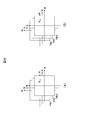
- FIG. 1 is an overall configuration diagram of a motor drive system including a motor control device 200.
- the motor drive system includes a DC power supply 100, a motor control device 200, and a motor 300.
- the motor control device 200 converts the DC power supplied from the DC power supply 100 into AC power to drive the motor 300.
- the DC power supply 100 is mainly a secondary battery, such as a lithium ion battery or a nickel hydrogen battery.
- the motor control device 200 includes a first inverter circuit 201, a second inverter circuit 202, a smoothing capacitor 203, a first current sensor 204, a second current sensor 205, a magnetic pole position sensor 206, a magnetic pole position detector 207, and a control unit 208.
- the PWM signal drive circuit 209 is provided.
- the first inverter circuit 201 has switching elements corresponding to the upper arm and the lower arm of the U phase, the V phase, and the W phase, respectively.
- the switching element is composed of an IGBT 221 and a diode 222, and the upper arm and the lower arm are packaged into one to form a power module 223.
- the switching element may be a MOSFET (metal oxide semiconductor field effect transistor).
- the first inverter circuit 201 forms a three-phase bridge circuit using three power modules 223, and switches the energization of each winding of the first system winding set 301 of the motor 300.
- the power module 223 may include a total of six switching elements of three-phase upper and lower arms in one package.
- the second inverter circuit 202 is a redundant inverter configuration provided in parallel with the first inverter circuit 201 for the DC power supply 100 and the smoothing capacitor 203. Since the configuration of the second inverter circuit 202 is the same as that of the first inverter circuit 201, the description thereof will be omitted.
- the second inverter circuit 202 constitutes a three-phase bridge circuit using a power module, and switches the energization of each winding of the second system winding set 302 of the motor 300.
- the smoothing capacitor 203 suppresses and smoothes the pulsation of the voltage input from the DC power supply 100 to the first inverter circuit 201 and the second inverter circuit 202.
- the first inverter circuit 201 and the second inverter circuit 202 may be collectively referred to as the inverter circuits 201 and 202.
- the voltage detector 101 detects the DC voltage value of the DC power supply 100 and outputs the detected value to the control unit 208.
- a first current sensor 204 is provided between the output line of the first inverter circuit 201 and the motor 300.
- a second current sensor 205 is provided between the output line of the second inverter circuit 202 and the motor 300.
- the first current sensor 204 detects the three-phase alternating currents Iu1, Iv1, and Iw1 of the first system that energize the motor 300 (U-phase alternating current Iu1, V-phase alternating current Iv1, and W-phase alternating current Iw1).
- the second current sensor 205 detects the three-phase alternating currents Iu2, Iv2, and Iw2 (U-phase alternating current Iu2, V-phase alternating current Iv2, and W-phase alternating current Iw2) of the second system that energize the motor 300.
- the first current sensor 204 and the second current sensor 205 are configured by using, for example, a Hall current sensor or the like.
- the detection results of the two systems of three-phase AC currents Iu1, Iv1, Iw1, Iu2, Iv2, and Iw2 by the first current sensor 204 and the second current sensor 205 are input to the control unit 208, and the gate signal performed by the control unit 208. Used for generation.
- the first current sensor 204 and the second current sensor 205 are composed of three current sensors in each of the first system and the second system.
- the remaining one-phase alternating current may be calculated because the sum of the three-phase alternating currents Iu, Iv, and Iw is zero. Further, the pulsed DC current flowing from the DC power supply 100 into the inverter circuits 201 and 202 is detected by a shunt resistor inserted between the smoothing capacitor 203 and the inverter circuits 201 and 202.
- the two systems of three-phase AC currents Iu1 and Iv1 , Iw1, Iu2, Iv2, Iw2 may be obtained.
- the motor 300 is equipped with a magnetic pole position sensor 206 for detecting the magnetic position ⁇ .
- the magnetic pole position sensor 206 is more preferably a resolver composed of an iron core and a winding, but there is no problem even if it is a sensor using a magnetoresistive element such as a GMR sensor or a Hall element.
- the signal from the magnetic pole position sensor 206 is input to the magnetic pole position detector 207.
- the magnetic pole position detector 207 calculates the magnetic pole position ⁇ from the input signal.
- the magnetic pole position detector 207 does not use the input signal from the magnetic pole position sensor 206, and has two three-phase alternating currents Iu1, Iv1, Iw1, Iu2, Iv2, and Iw2 flowing through the motor 300, and inverter circuits 201 and 202.
- the magnetic position ⁇ may be estimated using the two systems of three-phase AC voltages Vu1, Vv1, Vw1, Vu2, Vv2, and Vw2 applied to the motor 300.
- the current values from the first current sensor 204 and the second current sensor 205 and the magnetic position ⁇ from the magnetic pole position detector 207 are input to the control unit 208, and further, according to the target torque from the host controller or the like (not shown).
- the torque command value T * is input.
- the magnetic position ⁇ is used in the phase control of AC power performed by the control unit 208 generating a gate signal in accordance with the phase of the induced voltage of the motor 300.
- the control unit 208 generates a PWM signal for driving the motor 300 by performing PWM control based on the input information, and outputs the PWM signal to the PWM signal drive circuit 209.
- the PWM signal drive circuit 209 generates a gate signal for controlling each switching element of the first inverter circuit 201 and the second inverter circuit 202 based on the PWM signal input from the control unit 208, and the inverter circuit 201 , 202 is output.
- the switching elements are controlled according to the gate signal input from the PWM signal drive circuit 209, so that the DC power supplied from the DC power supply 100 is converted into AC power and output to the motor 300.
- the smoothing capacitor 203 smoothes the DC power supplied from the DC power supply 100 to the inverter circuits 201 and 202.
- the motor 300 is a synchronous motor that is rotationally driven by AC power supplied from the inverter circuits 201 and 202, and has a stator and a rotor.
- the stator of the motor 300 is provided with two systems of three-phase windings, that is, a first system winding group 301 and a second system winding group 302.
- AC power is input to the first system winding group 301 from the first inverter circuit 201, and three-phase AC currents Iu1, Iv1, and Iw1 are conducted to each winding constituting the first system winding group 301, and each winding is connected to the three-phase AC currents Iu1, Iv1, and Iw1. Armature magnetic flux is generated.
- AC power is input to the second system winding group 302 from the second inverter circuit 202, and three-phase AC currents Iu2, Iv2, and Iw2 are conducted to each winding constituting the second system winding group 302.
- Armature magnetic flux is generated in each winding.
- Torque is generated in the rotor by generating attractive and repulsive forces between the combined magnetic flux of the armature magnetic flux generated in each winding of these two systems and the magnet magnetic flux of the permanent magnets arranged in the rotor.
- the rotor is rotationally driven.
- control unit 208 and the PWM signal drive circuit 209 are shown as one each, but each of the inverter circuits 201 and 202 may have a PWM signal drive circuit and one control unit 208. Further, each of the inverter circuits 201 and 202 may have a PWM signal drive circuit 209 and a control unit 208, respectively.
- a storage unit 218 for storing various maps is connected to the control unit 208.
- the control unit 208 generates PWM signals for controlling the operations of the first inverter circuit 201 and the second inverter circuit 202, respectively, based on the pulsation of the electromagnetic force caused by the magnetic circuit of the motor 300. Shifts the phase of the PWM carrier signal used in. At that time, processing is performed with reference to the map stored in advance in the storage unit 218.
- the control unit 208 is, for example, a microcomputer.
- the storage unit 218 may be provided inside the control unit 208.
- the motor 300 is driven by a sinusoidal current, but the motor 300 that operates at a variable speed has a current flowing from the inverter circuits 201 and 202 to the motor 300 according to the rotation speed of the motor 300. Since it is necessary to control the frequency, most of the motors 300 that perform variable speed operation are driven by the inverter circuits 201 and 202.
- the PWM control performed by the control unit 208 is classified into two methods according to the difference in the control form of the frequency (carrier frequency) of the PWM carrier signal used for generating the PWM signal. Specifically, asynchronous PWM control in which the carrier frequency is constant regardless of the frequency of the current flowing through the motor 300, and synchronous PWM control in which the carrier frequency is controlled to be an integral multiple of the frequency of the current flowing through the motor 300. There is control.
- the motor 300 is driven at high speed by using the asynchronous PWM control, the current waveform flowing through the motor 300 does not become a three-phase symmetric waveform, which causes electromagnetic force pulsation of the motor 300.
- the synchronous PWM control is used, the current waveform flowing through the motor 300 becomes a three-phase symmetric waveform, so that the effect of reducing the electromagnetic force pulsation of the motor 300 can be expected as compared with the asynchronous PWM control.
- the pulsation of the electromagnetic force generated by the motor 300 is a change in the electromagnetic force generated in the rotor by energizing the motor 300 from the inverter circuits 201 and 202.
- the pulsation of the electromagnetic force generated by the motor 300 is roughly classified into a torque ripple which is a pulsating component generated in the circumferential direction of the motor 300 and an electromagnetic exciting force which is a pulsating component generated in the radial direction of the motor 300.
- the cause of the pulsation of the electromagnetic force in the motor 300 depends on the shape of the motor magnetic circuit composed of the core of the stator, the coil of the stator, the core of the rotor, and the magnet of the rotor of the motor 300.
- the two main things are the change in electromagnetic force and the change in electromagnetic force generated by the harmonics contained in the current energized from the inverter circuits 201 and 202 to the coil of the motor 300 due to the control of the inverter circuits 201 and 202. Is.
- the high-speed motor 300 generally performs field weakening control, the magnitude and phase of the pulsation of the electromagnetic force caused by the magnetic circuit are different even if the torque is the same. Further, the size of the field weakening depends on the DC voltage of the DC power supply 100.
- the cause of the harmonic component included in the current energized from the inverter circuits 201 and 202 to the coil of the motor 300 is that the inverter circuits 201 and 202 are controlled by PWM control and the voltage is applied by a PWM signal instead of a sine wave. Because it has been done. The pulse amplitude of this PWM signal depends on the DC voltage.
- a motor drive system in which two inverter circuits 201 and 202 are connected to a motor 300 having two independent windings of neutral points 303 and 304 on a stator, two windings are used.
- the pulsation of the electromagnetic force is determined by three factors.
- FIG. 2 is a diagram showing an example of torque ripple, which is a circumferential component of the pulsation of the electromagnetic force of the motor 300 when this embodiment is not applied.
- FIG. 2 (A) shows the torque acting on the shaft of the motor 300
- FIG. 2 (B) shows the circumferential component of the pulsation of the electromagnetic force caused by the magnetic circuit of the motor 300
- FIG. 2 (C) shows the first.
- the circumferential component of the pulsation of the electromagnetic force generated in the motor due to the control of the inverter circuit 201 is shown in FIG. 2 (D). It is a figure which shows the circumferential component.
- the horizontal axis represents the electrical angle and the vertical axis represents the torque.
- FIG. 2 (B), FIG. 2 (C) and FIG. 2 (D) the torque ripple which is a circumferential component of the pulsation of the electromagnetic force due to each factor in the motor 300 is shown.
- FIG. 3 is a diagram showing an example of torque ripple, which is a circumferential component of the pulsation of the electromagnetic force of the motor 300 when the present embodiment is applied.
- FIG. 3A shows the torque of the shaft of the motor 300
- FIG. 3B shows the circumferential component of the pulsation of the electromagnetic force caused by the magnetic circuit of the motor 300
- FIG. 3C shows the first inverter.
- FIG. 3D shows a circumferential component of the pulsation of the electromagnetic force caused by the control of the circuit 201
- FIG. 3D shows a circumferential component of the pulsation of the electromagnetic force caused by the control of the second inverter circuit 202.
- the horizontal axis represents the electrical angle and the vertical axis represents the torque.
- FIG. 3B, FIG. 3C, and FIG. 3D similarly to FIG. 2, the torque ripple which is a circumferential component of the pulsation of the electromagnetic force due to each factor in the motor 300 is shown.
- the torque ripple finally generated by the motor 300 can be reduced by adjusting the phase of the pulsation of the electromagnetic force of three factors by the control described later.
- the controllable elements are the electromagnetic force pulsation caused by the control of the first inverter circuit 201 and the electromagnetic force pulsation caused by the control of the second inverter circuit 202.
- the control unit 208 controls the phase ⁇ I1 of the electromagnetic force pulsation caused by the control of the first inverter circuit 201 and the control of the second inverter circuit 202 with reference to the electromagnetic force pulsation caused by the magnetic circuit of the motor 300.
- the phase ⁇ I2 of the pulsation of the electromagnetic force caused by the above is adjusted.
- the adjustment of the phase ⁇ I1 of the pulsation of the electromagnetic force caused by the control of the first inverter circuit 201 is the phase of the PWM carrier signal used to generate the PWM signal for controlling the first inverter circuit 201 (carrier phase ⁇ C1 ).
- the adjustment of the phase ⁇ I2 of the pulsation of the electromagnetic force caused by the control of the second inverter circuit 202 is the phase of the PWM carrier signal used to generate the PWM signal for controlling the second inverter circuit 202 (carrier phase ⁇ C2 ). To adjust.
- the pulsation of the electromagnetic force caused by the control of the first inverter circuit 201 is applied to the pulsation of the electromagnetic force caused by the magnetic circuit of the motor 300 shown in FIG. 3 (B). For example, shift by 20 degrees. Further, for example, with respect to the pulsation of the electromagnetic force caused by the control of the second inverter circuit 202 shown in FIG. 3 (D) and the pulsation of the electromagnetic force caused by the magnetic circuit of the motor 300 shown in FIG. 3 (B). For example, shift by 40 degrees.
- the pulsation generated in the torque of the shaft of the motor 300 can be suppressed, and the vibration and noise of the motor 300 can be suppressed.
- the carrier phases ⁇ C1 and ⁇ C2 are adjusted, respectively, and the phase ⁇ I1 of the circumferential component in the electromagnetic force pulsation caused by the control of the first inverter circuit 201 and the control of the second inverter circuit 202 are caused.
- the torque ripple which is the circumferential component of the electromagnetic force pulsation generated in the motor 300
- the phase ⁇ I2 of the circumferential component in the electromagnetic force pulsation is reduced by adjusting the phase ⁇ I2 of the circumferential component in the electromagnetic force pulsation.
- the electromagnetic excitation force which is a radial component of the electromagnetic force pulsation generated in the motor 300.
- the phase of the radial component in the electromagnetic force pulsation caused by the control of the first inverter circuit 201 and the electromagnetic force pulsation caused by the control of the second inverter circuit 202 By adjusting the phase of the radial component, the electromagnetic excitation force, which is the radial component of the electromagnetic force pulsation generated in the motor 300, can be reduced.
- FIG. 4 (A) and 4 (B) are diagrams showing a motor pulsation map.
- FIG. 4A is a pulsation map of the electromagnetic force for the circumferential component of the motor 300
- FIG. 4B is a pulsation map of the electromagnetic force for the radial component of the motor 300. Both are stored in advance in the storage unit 218.
- the pulsation map of the electromagnetic force for the circumferential component of the motor 300 includes the current command values Id and Iq when controlling the motor 300 and the electromagnetic force caused by the magnetic circuit of the motor 300. It is a map associating with the phase ⁇ Tr of the pulsation of. This map is set corresponding to the DC voltages Vdc1, Vdc2, and Vdc3 of the DC power supply 100, respectively.
- Vdc1, Vdc2, and Vdc3 the motor pulsation map for the circumferential component is shown. May be set corresponding to a plurality of DC voltages, and may be other than three.
- the pulsation map of the electromagnetic force for the radial component of the motor 300 shows the current command values Id and Iq when controlling the motor 300 and the pulsation caused by the magnetic circuit of the motor 300. It is a map associated with the phase ⁇ Tr. This map is set corresponding to the DC voltages Vdc1, Vdc2, and Vdc3 of the DC power supply 100, respectively.
- Vdc1, Vdc2, and Vdc3 for convenience of explanation, an example in which a motor pulsation map for radial components is set for three DC voltages Vdc1, Vdc2, and Vdc3 is shown, but the motor pulsation map for radial components is shown. It suffices as long as it is set corresponding to a plurality of DC voltages, and may be other than three.
- the motor pulsation maps shown in FIGS. 4 (A) and 4 (B) are stored in advance using experimental values and design values. For example, when the motor drive system shown in FIG. 1 is operated and the DC voltage Vdc1 of the DC power supply 100 is used, a certain current command value Id, Iq and the pulsation of the electromagnetic force caused by the magnetic circuit of the motor 300 in that case Find the phase ⁇ Tr and use it as a map. Then, the current command values Id and Iq are variously changed to obtain the phase ⁇ Tr of each electromagnetic force pulsation, which is used as a map. Hereinafter, similarly, the DC voltage of the DC power supply 100 is changed to obtain a map.
- the motor pulsation map shows the magnitude of the pulsation of the electromagnetic force (torque ripple generated in the circumferential direction and the electromagnetic excitation force generated in the radial direction) caused by the magnetic circuit of the motor 300 based on the current command values id and iq, and the magnitude of the electromagnetic excitation force of the motor 300.
- the reference phase with respect to the electric angle is also stored in advance.
- the current command values Id, Iq refer to the map for the circumferential component shown in FIG. 4 (A).
- the phase ⁇ Tr of the electromagnetic force pulsation corresponding to is obtained with reference to the map for the radial component shown in FIG. 4 (B).
- FIG. 5 (A) and 5 (B) are diagrams showing a circumferential carrier phase map.
- FIG. 5A is a carrier phase map for the first circumferential component of the first inverter circuit 201
- FIG. 5B is a carrier phase map for the second circumferential component of the second inverter circuit 202. be. Both are stored in advance in the storage unit 218.
- the carrier phase map for the first circumferential component of the first inverter circuit 201 includes the current command values Id and Iq when controlling the motor 300 and the control of the first inverter circuit 201. It is a map associated with the carrier phase ⁇ C1 for reducing the circumferential component of the electromagnetic force pulsation caused by.
- the carrier phase map for the second circumferential component of the second inverter circuit 202 includes the current command values Id and Iq when controlling the motor 300 and the control of the second inverter circuit 202. It is a map associated with the carrier phase ⁇ C2 for reducing the circumferential component of the electromagnetic force pulsation caused by.
- These maps are set corresponding to the DC voltages Vdc1, Vdc2, and Vdc3 of the DC power supply 100, respectively.
- the carrier phase map for the first circumferential component and the carrier for the second circumferential component are provided for the three DC voltages Vdc1, Vdc2, and Vdc3.
- An example in which each phase map is set is shown, but these maps may be set corresponding to a plurality of DC voltages, and may be other than three.
- FIG. 6 (A) and 6 (B) are diagrams showing a radial carrier phase map.
- FIG. 6A is a carrier phase map for the first radial component of the first inverter circuit 201
- FIG. 6B is a carrier phase map for the second radial component of the second inverter circuit 202. be. Both are stored in advance in the storage unit 218.
- the carrier phase map for the first radial component of the first inverter circuit 201 includes the current command values Id and Iq when controlling the motor 300 and the control of the first inverter circuit 201. It is a map associated with the carrier phase ⁇ C1 for reducing the radial component of the electromagnetic force pulsation caused by.
- the carrier phase map for the second radial component of the second inverter circuit 202 includes the current command values Id and Iq when controlling the motor 300 and the control of the second inverter circuit 202. It is a map associated with the carrier phase ⁇ C2 for reducing the radial component of the electromagnetic force pulsation caused by.
- These maps are set corresponding to the DC voltages Vdc1, Vdc2, and Vdc3 of the DC power supply 100, respectively.
- the carrier phase map for the first radial component and the carrier for the second radial component are provided for the three DC voltages Vdc1, Vdc2, and Vdc3.
- An example in which each phase map is set is shown, but these maps may be set corresponding to a plurality of DC voltages, and may be other than three.
- the carrier phases ⁇ C1 and ⁇ C2 in the circumferential carrier phase maps of FIGS. 5 (A) and 5 (B) and the radial carrier phase maps of FIGS. 6 (A) and 6 (B) are shown in FIGS. It is represented with reference to the phase ⁇ Tr in the motor pulsation map of 4 (A) and 4 (B), respectively. That is, the phase difference between the electromagnetic force pulsation caused by the magnetic circuit of the motor 300 and each PWM carrier signal for reducing the electromagnetic force pulsation caused by the control of the first inverter circuit 201 and the second inverter circuit 202 is determined. It is represented by the circumferential carrier phase map of FIGS. 5 (A) and 5 (B) and the radial carrier phase map of FIGS. 6 (A) and 6 (B), respectively.
- the PWM carrier phase maps of the circumferential components shown in FIGS. 5 (A) and 5 (B) are stored in advance using experimental values and design values. For example, when the motor drive system shown in FIG. 1 is operated and the DC voltage Vdc1 of the DC power supply 100 is used, certain current command values Id and Iq and the control of the first inverter circuit 201 and the second inverter circuit 202 in that case are controlled.
- the carrier phases ⁇ C1 and ⁇ C2 that reduce the circumferential component of the pulsation of the electromagnetic force caused by the above are obtained and used as a map.
- the phase of the PWM carrier signal of the first inverter circuit 201 is shifted, and the phase when the torque ripple of the motor 300 becomes the smallest is obtained as the carrier phase ⁇ C1 .
- the second inverter circuit 202 if the phase of the PWM carrier signal used for the PWM control of the inverter circuits 201 and 202 is shifted to the phases ⁇ C1 and ⁇ C2 , it means that the pulsation of the electromagnetic force in the circumferential direction caused by these controls can be minimized. ..
- the current command values Id and Iq are changed in various ways to obtain the carrier phases ⁇ C1 and ⁇ C2 in each case, which are used as a map.
- the DC voltage of the DC power supply 100 is changed to obtain a map.
- the PWM carrier phase maps of the radial components shown in FIGS. 6 (A) and 6 (B) are also stored in advance using experimental values and design values. For example, when the motor drive system shown in FIG. 1 is operated and the DC voltage Vdc1 of the DC power supply 100 is used, certain current command values Id and Iq and the control of the first inverter circuit 201 and the second inverter circuit 202 in that case are controlled.
- the carrier phases ⁇ C1 and ⁇ C2 that reduce the radial component of the pulsation of the electromagnetic force caused by the above are obtained and used as a map.
- the current command values Id and Iq are changed in various ways to obtain the carrier phases ⁇ C1 and ⁇ C2 in each case, which are used as a map.
- the DC voltage of the DC power supply 100 is changed to obtain a map.
- the map for the circumferential component shown in FIGS. 5 (A) and 5 (B) is referred to.
- the carrier phases ⁇ C1 and ⁇ C2 corresponding to the current command values Id and Iq are referred to with reference to the maps for the radial components shown in FIGS. 6 (A) and 6 (B).
- FIG. 7 is a diagram showing the relationship between the rotation speed of the motor 300 and the excitation frequency (frequency of pulsation in the radial direction).
- the horizontal axis represents the rotation speed of the motor 300, and the vertical axis represents the excitation frequency.
- Asynchronous PWM control is used until the rotation speed of the motor 300 is up to 12000 rpm, and synchronous PWM control is used when the rotation speed of the motor 300 exceeds 12000 rpm.
- the electric angle (fundamental wave current) that rotates the motor 300 is defined as the frequency f1 [Hz].
- the relationship between the rotation speed N [rpm] of the motor 300 and the electric angular frequency f1 is expressed by the following equation (1).
- P is the number of poles of the motor 300.
- f1 N / 60 ⁇ P / 2 [rpm] ⁇ ⁇ ⁇ (1)
- the excitation frequency f6 of the sixth rotation (electrical angle) of the motor 300 is represented by the following equation (2).
- the illustrated f6 is the rotation 6th order (electrical angle) excitation frequency f6
- the illustrated f12 is the rotation 12th order (electrical angle) excitation frequency f12.
- the excitation frequencies f6 and f12 increase linearly from the area of asynchronous PWM control to the area of synchronous PWM control.
- the carrier frequency fc is constant in asynchronous PWM control.
- the sideband wave components of the carrier frequencies fc and fc ⁇ 3f1 are the 0th-order excitation frequencies of the annulus.
- the 0th order of the annulus is the rotation order of the radial pulsation of the motor 300.
- the radial component of the electromagnetic force generated in the gap of the motor 300 which changes uniformly over time in the radial direction, is referred to as an annular zero-order mode.
- the pulsation of the electromagnetic force in the radial direction of the motor 300 is reduced for the radial pulsation of the 0th order of the annulus.
- the frequencies f6 and f12 of the pulsation of the electromagnetic force in the radial direction caused by the magnetic circuit of the motor 300 and the radial directions caused by the control of the inverter circuits 201 and 202 overlap.
- the radial electromagnetic force pulsation caused by the magnetic circuit of the motor 300 and the radial electromagnetic force pulsation caused by the control of the inverter circuits 201 and 202 have the same frequency.
- FIG. 8A and 8B are diagrams showing the frequency of the voltage command and the carrier frequency fc.
- FIG. 8A shows the waveform of the first inverter circuit 201
- FIG. 8B shows the waveform of the second inverter circuit 202. show.
- the left side of each figure shows the case where the rotation speed of the motor 300 is low
- the right side of each figure shows the case where the rotation speed of the motor 300 is high.
- the control of the control unit 208 shown in FIG. 1 is synchronous PWM control, and the control unit 208 controls the frequency of the voltage command and the carrier frequency fc.
- the frequency of the voltage command is the frequency f1 [Hz] of the electric angle (fundamental wave current) that turns the motor 300.
- the carrier frequency fc is controlled to form a PWM carrier signal of 9 pulses for each cycle of the voltage command frequency f1.
- NS As shown on the right side of FIGS. 8 (A) and 8 (B), similarly, the carrier frequency fc forms a PWM carrier signal of 9 pulses for each cycle of the voltage command frequency f1 even at high rotation speeds. Be controlled.
- the waveform obtained by the first inverter circuit 201 and the waveform obtained by the second inverter circuit 202 are similar waveforms.
- the frequency of the PWM carrier signal may be an integral multiple of the frequency of the voltage command.
- this integral multiple it is preferable to control this integral multiple to be an odd integer multiple, or to control it to be an integral multiple of a multiple of 3.
- the frequency of the PWM carrier signal used in the PWM control of the first inverter circuit 201 and the second inverter circuit 202 is set to the frequency f1 of the voltage command for driving the motor 300.
- the carrier frequency fc is adjusted so as to be an integral multiple of the frequency of the voltage command to be driven.
- the pulsation of the electromagnetic force caused by the magnetic circuit of the motor 300 is shifted by shifting the phase of the pulsation of the electromagnetic force caused by the control of the inverter circuits 201 and 202 by the control described later. Can be offset.
- FIG. 9 is a flowchart showing the processing of the control unit 208 of the motor control device 200.
- the flowchart shown in FIG. 9 is executed at regular intervals or every time a torque command value T * is input.
- the program shown in this flowchart can be executed by a computer equipped with a CPU, memory, and the like. All processing or some processing may be realized by a hard logic circuit. Further, this program can be provided by being stored in a storage medium of the motor control device 200 in advance. Alternatively, the program can be stored and provided in an independent storage medium, or the program can be recorded and stored in the storage medium of the motor control device 200 via a network line. It may be supplied as a computer-readable computer program product in various forms such as a data signal (carrier wave).
- step S901 of FIG. 9 the control unit 208 receives the torque command value T * from the host controller or the like. Then, in step S902, the control unit 208 creates the current command values Id and Iq from the received torque command value T *.
- step S903 the control unit 208 adjusts the frequency of the PWM carrier signal to be an integral multiple of the frequency of the voltage command, as described with reference to FIGS. 8A and 8B. do. At this time, for example, it is desirable to adjust the integer multiple to an odd integer multiple and to an integer multiple of a multiple of 3.
- step S904 the control unit 208 selects the pulsating component to be reduced. That is, when the rotation speed of the motor 300 is lower than a predetermined value, a circumferential component is selected, and when the rotation speed of the motor 300 is a predetermined value or more, a radial component is selected.
- the value of the rotation speed of the motor 300 is determined based on the rotation position ⁇ from the magnetic pole position detector 207.
- the control unit 208 determines the torque ripple generated in the circumferential direction among the electromagnetic force pulsations caused by the magnetic circuit of the motor 300 and the electromagnetic force pulsation caused by the magnetic circuit of the motor 300 based on the rotation speed of the motor 300. Select one of the electromagnetic excitation forces generated in the radial direction.
- step S905 the control unit 208 searches for the motor pulsation map stored in the storage unit 218.
- the motor pulsation map includes a map for the circumferential component shown in FIG. 4 (A) and a map for the radial component shown in FIG. 4 (B). Since the pulsating component to be reduced is selected in step S904, the map corresponding to the selected pulsating component is searched.
- the control unit 208 detects the DC voltage value of the DC power supply 100 from the voltage detector 101. That is, when the rotation speed is lower than the predetermined value, among the maps for the three circumferential components shown in FIG.
- the map corresponding to the detected DC voltage value of the DC power supply 100 is the current command value Id, Iq.
- the phase ⁇ Tr of the pulsation of the electromagnetic force caused by the magnetic circuit of the motor 300 is acquired by searching based on.
- the map corresponding to the detected DC voltage value of the DC power supply 100 is based on the current command values Id and Iq. And obtains the phase ⁇ Tr of the pulsation of the electromagnetic force caused by the magnetic circuit of the motor 300.
- a change in the DC voltage of the DC power supply 100 changes the amplitude of the pulsation of the electromagnetic force caused by the magnetic circuit of the motor 300.
- the map corresponding to the DC voltage value detected by the voltage detector 101 is referred to, so that the amplitude can be changed. can do.
- step S906 the control unit 208 estimates the phase of the pulsation caused by the magnetic circuit of the motor 300 from the phase ⁇ Tr searched in step S905.
- the control unit 208 estimates the phase of the pulsation caused by the magnetic circuit of the motor 300 from the phase ⁇ Tr searched in step S905.
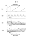
- FIG. 10 is a diagram showing torque ripple when this embodiment is applied.
- FIG. 10A is a diagram showing the magnetic position of the motor 300, in which the horizontal axis represents time and the vertical axis represents the electric angle.
- FIG. 10B shows the torque of the shaft of the motor 300, the horizontal axis represents time, and the vertical axis represents torque.
- FIG. 10C is a diagram showing a PWM carrier signal and voltage command of the first inverter circuit 201
- FIG. 10D is a diagram showing a PWM carrier signal and voltage command of the second inverter circuit 202
- the horizontal axis is time.
- the vertical axis represents the voltage.
- the magnetic position of the motor 300 changes every 360 degrees of the electric angle as the motor 300 rotates, and the rotation angle of 0 degrees becomes the reference position.
- the control unit 208 estimates the phase of the pulsation caused by the magnetic circuit of the motor 300 by using the detection signal of the magnetic pole position detector 207 attached to the motor 300 and the current command value to the motor 300. Since the pulsation of the electromagnetic force caused by the magnetic circuit with respect to the rotation angle of the motor 300 can be estimated, the carrier phase ⁇ C1 and the carrier phase ⁇ C1 and as shown in FIGS. ⁇ C2 can be adjusted.
- the control unit 208 searches for the carrier phase map stored in the storage unit 218.
- the carrier phase map includes the circumferential carrier phase map shown in FIGS. 5 (A) and 5 (B) and the radial carrier phase map shown in FIGS. 6 (A) and 6 (B). ..
- the map corresponding to the selected pulsating component is searched.
- the control unit 208 detects the DC voltage value of the DC power supply 100 from the voltage detector 101. That is, when the rotation speed is lower than the predetermined value, the map corresponding to the detected DC voltage value of the DC power supply 100 among the maps for the three circumferential components shown in FIGS. 5 (A) and 5 (B), respectively. Is searched based on the current command values Id and Iq, respectively, and the carrier phases ⁇ C1 and ⁇ C2 are acquired.
- the map corresponding to the detected DC voltage value of the DC power supply 100 among the maps for the three radial components shown in FIGS. 6 (A) and 6 (B) is used as the current. Search based on the command values Id and Iq, respectively, and acquire the carrier phases ⁇ C1 and ⁇ C 2.
- step S908 of FIG. 9 the control unit 208 shifts the PWM carrier signal to the first inverter circuit 201 by the phase ⁇ C1 with reference to the pulsation of the electromagnetic force caused by the magnetic circuit of the motor 300. Further, the PWM carrier signal with respect to the second inverter circuit 202 is shifted by the phase ⁇ C2 with reference to the pulsation of the electromagnetic force caused by the magnetic circuit of the motor 300.
- step S909 the control unit 208 drives the first inverter circuit 201 and the second inverter circuit 202 to output an AC voltage to the motor 300.
- phase of the PWM carrier signal is shifted with reference to the pulsation of the electromagnetic force caused by the magnetic circuit of the motor 300 by the combined wave of the harmonic currents energized by the first inverter circuit and the second inverter circuit. do.
- pulsation caused by the magnetic circuit of the motor 300 can be suppressed.
- FIG. 3C shows an example of shifting the pulsation of the electromagnetic force caused by the control of the first inverter circuit 201 by 20 degrees
- FIG. 3D shows the pulsation of the electromagnetic force caused by the control of the second inverter circuit 202. Is shown by shifting 40 degrees.
- the adjustment of the phase ⁇ I1 of the pulsation of the electromagnetic force caused by the control of the first inverter circuit 201 is performed by adjusting the carrier phase ⁇ C1 of the first inverter circuit 201.
- the phase ⁇ I2 of the pulsation of the electromagnetic force caused by the control of the second inverter circuit 202 is adjusted by adjusting the carrier phase ⁇ C2 of the second inverter circuit 202.
- torque ripple generated in the axial direction of the motor 300 and electromagnetic excitation force generated in the radial direction of the motor 300 can be suppressed, and vibration and noise of the motor 300 can be suppressed. It can be suppressed.
- the radial carrier phase maps shown in FIGS. 6 (A) and 6 (B) are selected and used. That is, one of the torque ripple generated in the circumferential direction of the pulsation caused by the magnetic circuit of the motor 300 and the electromagnetic exciting force generated in the radial direction of the pulsation caused by the magnetic circuit of the motor 300 based on the rotational speed of the motor 300. Select to shift the phase of the PWM carrier signal to reduce the selected torque ripple or electromagnetic excitation force.
- the motor pulsation maps shown in FIGS. 4 (A) and 4 (B), FIGS. 5 (A), and 5 (B) are shown according to the DC voltage value of the DC power supply 100 detected by the voltage detector 101.
- the circumferential carrier phase map shown in B) and the radial carrier phase map shown in FIGS. 6 (A) and 6 (B) are selected and used. That is, the phase shift amount of the PWM carrier signal is adjusted based on the DC voltage applied to the first inverter circuit 201 and the second inverter circuit 202.
- the amplitude of the pulsation of the electromagnetic force caused by the control of the first inverter circuit 201 and the second inverter circuit 202 changes due to the change in the DC voltage of the DC power supply 100, but even if these amplitudes change. It is possible to secure the effect of reducing the torque ripple and the electromagnetic excitation force when superposed with the pulsation of the electromagnetic force caused by the magnetic circuit of the motor 300.
- FIG. 11A is a diagram showing the magnetic position of the motor 300, in which the horizontal axis represents time and the vertical axis represents the electric angle.
- FIG. 11B shows the torque ripple of the shaft of the motor 300, where the horizontal axis represents time and the vertical axis represents torque.
- FIG. 11C is a diagram showing a sixth-order electric angle component of torque ripple, and
- FIG. 11D is a diagram showing a twelfth-order electric angle component of torque ripple.
- the horizontal axis represents time and the vertical axis represents torque. ..
- the torque ripple on the shaft of the motor 300 shown in FIG. 11B indicates the pulsation of the electromagnetic force caused by the magnetic circuit of the motor 300.
- the pulsation of the electromagnetic force caused by the magnetic circuit of the motor 300 shown in FIG. 11 (B) is cut out for one electric angle cycle (360 degrees) shown in FIG. 11 (A), and the component analysis is performed. , FIG. 11 (D). That is, the waveform of FIG.
- 11C has six pulsations of the electromagnetic force in one cycle of the electric angle (360 degrees), and pulsates six times for one rotation of the electric angle, so that it is called a sixth-order component of the electric angle.
- the waveform of FIG. 11 (D) has 12 pulsations of electromagnetic force in one cycle of electric angle (360 degrees), and pulsates 12 times for one rotation of electric angle, so that it is called an electric angle 12th order component.
- FIG. 12 is a diagram showing pulsation when this embodiment is applied.
- 12 (A) shows the torque of the shaft of the motor 300
- FIG. 12 (B) shows the pulsation of the electromagnetic force caused by the magnetic circuit of the motor 300
- FIG. 12 (C) shows the control of the first inverter circuit 201
- FIG. 12 (D) is a diagram showing the pulsation of the electromagnetic force caused by the control of the second inverter circuit 202.
- the horizontal axis represents the electrical angle and the vertical axis represents the torque.
- step S908 of FIG. 9 In the control for reducing the pulsation of the electromagnetic force of the sixth-order electric angle component, the same processing as in steps S901 to S907 and S909 described with reference to FIG. 9 is performed, but in step S908 of FIG. 9, the following processing is performed. ..
- the control unit 208 sets the phase ⁇ I1 of the electromagnetic force pulsation caused by the control of the first inverter circuit 201 with reference to the electromagnetic force pulsation caused by the magnetic circuit of the motor 300. Shift 30 degrees. Further, as shown in FIG. 12D, the control unit 208 uses the pulsation of the electromagnetic force caused by the magnetic circuit of the motor 300 as a reference, and the phase ⁇ of the pulsation of the electromagnetic force caused by the control of the second inverter circuit 202. Shift I2 by 30 degrees.
- FIG. 3 is a diagram showing the pulsation of the electromagnetic force of the motor 300 when the present embodiment is applied.
- step S908 of FIG. Performs the following processing.
- the control unit 208 sets the phase ⁇ I1 of the electromagnetic force pulsation caused by the control of the first inverter circuit 201 with reference to the electromagnetic force pulsation caused by the magnetic circuit of the motor 300. Shift 20 degrees. Further, as shown in FIG. 3D, the control unit 208 uses the pulsation of the electromagnetic force caused by the magnetic circuit of the motor 300 as a reference, and the phase ⁇ of the pulsation of the electromagnetic force caused by the control of the second inverter circuit 202. Shift I2 by 40 degrees.
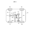
- FIG. 13 is a configuration diagram of the electric vehicle system according to the present embodiment. As shown in FIG. 13, the electric vehicle system has a power train to which the motor 300 is applied as a motor / generator, and travels by using the rotational driving force of the motor 300.
- the electric vehicle system will be described by taking a hybrid system as an example.
- a front wheel axle 801 is rotatably supported on the front portion of the electric vehicle 800, and front wheels 802 and 803 are provided at both ends of the front wheel axle 801.
- a rear wheel axle 804 is rotatably supported at the rear portion of the electric vehicle 800, and rear wheels 805 and 806 are provided at both ends of the rear wheel axle 804.
- a differential gear 811 which is a power distribution mechanism is provided in the central portion of the front wheel axle 801 to distribute the rotational driving force transmitted from the engine 810 via the transmission 812 to the left and right front wheel axles 801. ing.
- the engine 810 and the motor 300 are mechanically connected to each other via a belt between a pulley provided on the crankshaft of the engine 810 and a pulley provided on the rotating shaft of the motor 300.
- the rotational driving force of the motor 300 can be transmitted to the engine 810, and the rotational driving force of the engine 810 can be transmitted to the motor 300.
- the rotor rotates by supplying the three-phase AC power controlled by the motor control device 200 having the inverter circuits 201 and 202 built-in to the coil of the stator, and the motor 300 rotates according to the three-phase AC power. Generates driving force.
- the motor control device 200 is the device described above in this embodiment.
- the motor 300 while the motor 300 is controlled by the motor control device 200 and operates as an electric motor, the rotor rotates in response to the rotational driving force of the engine 810, so that an electromotive force is induced in the coil of the stator, resulting in three phases. It operates as a generator that generates AC power.
- the motor control device 200 is a power conversion device that converts DC power supplied from a DC power source 100, which is a high-pressure battery, into three-phase AC power, and is used as a stator coil of the motor 300 according to a magnetic position according to an operation command value. Controls the flowing three-phase alternating current.
- the three-phase AC power generated by the motor 300 is converted into DC power by the motor control device 200 to charge the DC power supply 100.
- the DC power supply 100 is electrically connected to the low voltage battery 823 via a DC-DC converter 824.
- the low-voltage battery 823 constitutes a low-voltage (14V) system power supply for the electric vehicle 800, and is used as a power supply for a starter 825, a radio, a light, etc. that initially starts (cold start) the engine 810.
- the vibration and noise of the motor 300 are generated by the exciting force generated by the electromagnetic force, which is transmitted to the main body of the motor 300 and the attached structure and shakes each part, so that the vibration noise is generated. Further, when the frequency overlaps with the intrinsic mode of the structure and the frequency and the excitation mode of the exciting force, a resonance state occurs and the vibration noise is amplified. In the present embodiment, the vibration and noise of the motor 300 can be reduced, and further, the vibration and noise of the electric vehicle 800 on which the motor 300 is mounted can be reduced.
- the motor control device 200 includes a redundant first inverter circuit 201 and a second inverter circuit 202 that control the motor 300, and a control unit 208 that controls the first inverter circuit 201 and the second inverter circuit 202.
- the first inverter circuit 201 converts DC power into AC power based on the PWM signal generated by using the first carrier signal
- the second inverter circuit 202 is generated by using the second carrier signal.
- the DC power is converted into AC power based on the PWM signal
- the control unit 208 sets the phases of the first carrier signal and the second carrier signal with reference to the pulsation of the electromagnetic force caused by the magnetic circuit of the motor 300. Shift each. As a result, vibration and noise generated in the motor can be suppressed.
- the motor control method is a motor control including a redundant first inverter circuit 201 and a second inverter circuit 202 for controlling the motor, and a control unit 208 for controlling the first inverter circuit 201 and the second inverter circuit 202.
- a motor control method in the device 200 in which the first inverter circuit 201 converts DC power into AC power based on the PWM signal generated by using the first carrier signal, and the second inverter circuit 202 converts the DC power into AC power.
- the DC power is converted into AC power based on the PWM signal generated by using the carrier signal of 2
- the control unit converts the first carrier signal and the pulsation of the electromagnetic force caused by the magnetic circuit of the motor 300 as a reference.
- a motor control method for shifting the phase of each of the second carrier signals As a result, vibration and noise generated in the motor can be suppressed.
Abstract
The purpose of the present invention is to sufficiently suppress vibration and noise generated in a motor. Provided is a motor control device comprising: redundant first inverter circuit and second inverter circuit for controlling a motor; and a control unit for controlling the first inverter circuit and the second inverter circuit, wherein the first inverter circuit converts the DC power into the AC power, on the basis of a PWM signal generated by using a first carrier signal, the second inverter circuit converts the DC power into the AC power, on the basis of a PWM signal generated by using a second carrier signal, and the control unit shifts the phases of the first carrier signal and the second carrier signal on the basis of the pulsation of the electromagnetic force caused by the magnetic circuit of the motor.
Description
本発明は、モータ制御装置、電動車両、およびモータ制御方法に関する。
The present invention relates to a motor control device, an electric vehicle, and a motor control method.
モータの制御装置において、2組の多相巻線組から構成される多相交流モータに対し、2組の巻線組に対応する2系統のインバータを備え、各巻線組への通電を制御する制御装置が知られている。
In the motor control device, for a multi-phase AC motor composed of two sets of multi-phase winding sets, two inverters corresponding to the two sets of winding sets are provided to control energization to each winding set. Control devices are known.
特許文献1には、多相交流モータの固定子を構成し回転子に回転磁界を作用させる2組の多相巻線組に対応して電気的に独立して設けられ、2組の多相巻線組に交流電圧を出力する2系統のインバータと、2組の多相巻線組に印加される交流電圧の位相差を制御する制御部とを備え、制御部は、位相差について、特定次数の高調波成分を低減可能な基準位相差を含む制御範囲を設定し、多相交流モータの要求特性に基づいて、又は、多相交流モータの通電にゆらぎを生じさせるように、制御範囲内で位相差を変化させる装置が記載されている。
In Patent Document 1, two sets of polyphases are electrically provided independently corresponding to two sets of multi-phase winding sets that form a stator of a multi-phase AC motor and apply a rotating magnetic field to the rotor. It is equipped with two systems of inverters that output AC voltage to the winding set and a control unit that controls the phase difference of the AC voltage applied to the two sets of multi-phase winding sets, and the control unit specifies the phase difference. Set the control range including the reference phase difference that can reduce the harmonic component of the order, and within the control range based on the required characteristics of the multi-phase AC motor or so as to cause fluctuations in the energization of the multi-phase AC motor. A device for changing the phase difference is described in.
上述した、特許文献1に記載の装置では、モータにおいて発生する振動や騒音を十分に抑制することができなかった。
The above-mentioned device described in Patent Document 1 could not sufficiently suppress the vibration and noise generated in the motor.
本発明によるモータ制御装置は、モータを制御する冗長系の第1インバータ回路及び第2インバータ回路と、前記第1インバータ回路及び前記第2インバータ回路を制御する制御部とを備えるモータ制御装置であって、前記第1インバータ回路は、第1のキャリア信号を用いて生成されるPWM信号に基づいて前記直流電力を前記交流電力に変換し、前記第2インバータ回路は、第2のキャリア信号を用いて生成されるPWM信号に基づいて前記直流電力を前記交流電力に変換し、前記制御部は、前記モータの磁気回路に起因する電磁力の脈動を基準として、前記第1のキャリア信号および前記第2のキャリア信号の位相をそれぞれシフトする。
本発明によるモータ制御方法は、モータを制御する冗長系の第1インバータ回路及び第2インバータ回路と、前記第1インバータ回路及び前記第2インバータ回路を制御する制御部とを備えるモータ制御装置におけるモータ制御方法であって、前記第1インバータ回路により、第1のキャリア信号を用いて生成されるPWM信号に基づいて前記直流電力を前記交流電力に変換し、前記第2インバータ回路により、第2のキャリア信号を用いて生成されるPWM信号に基づいて前記直流電力を前記交流電力に変換し、前記制御部により、前記モータの磁気回路に起因する電磁力の脈動を基準として、前記第1のキャリア信号および前記第2のキャリア信号の位相をそれぞれシフトする。 The motor control device according to the present invention is a motor control device including a redundant first inverter circuit and a second inverter circuit for controlling a motor, and a control unit for controlling the first inverter circuit and the second inverter circuit. The first inverter circuit converts the DC power into the AC power based on the PWM signal generated by using the first carrier signal, and the second inverter circuit uses the second carrier signal. The DC power is converted into the AC power based on the PWM signal generated by the inverter, and the control unit uses the pulsation of the electromagnetic force caused by the magnetic circuit of the motor as a reference, and the first carrier signal and the first carrier signal. The phases of the two carrier signals are shifted respectively.
The motor control method according to the present invention is a motor in a motor control device including a redundant first inverter circuit and a second inverter circuit for controlling a motor, and a control unit for controlling the first inverter circuit and the second inverter circuit. It is a control method, in which the DC power is converted into the AC power based on the PWM signal generated by using the first carrier signal by the first inverter circuit, and the second inverter circuit converts the DC power into the AC power. The DC power is converted into the AC power based on the PWM signal generated by using the carrier signal, and the control unit converts the DC power into the AC power, and the control unit uses the pulsation of the electromagnetic force caused by the magnetic circuit of the motor as a reference as the first carrier. The phases of the signal and the second carrier signal are shifted, respectively.
本発明によれば、モータにおいて発生する振動や騒音を抑制することができる。
According to the present invention, vibration and noise generated in the motor can be suppressed.
図1は、モータ制御装置200を備えたモータ駆動システムの全体構成図である。
図1に示すように、モータ駆動システムは、直流電源100、モータ制御装置200、モータ300を備える。モータ制御装置200は、直流電源100から供給された直流電力を交流電力に変換して、モータ300を駆動する。直流電源100は主に二次電池であり、リチウムイオンバッテリやニッケル水素バッテリである。 FIG. 1 is an overall configuration diagram of a motor drive system including amotor control device 200.
As shown in FIG. 1, the motor drive system includes aDC power supply 100, a motor control device 200, and a motor 300. The motor control device 200 converts the DC power supplied from the DC power supply 100 into AC power to drive the motor 300. The DC power supply 100 is mainly a secondary battery, such as a lithium ion battery or a nickel hydrogen battery.
図1に示すように、モータ駆動システムは、直流電源100、モータ制御装置200、モータ300を備える。モータ制御装置200は、直流電源100から供給された直流電力を交流電力に変換して、モータ300を駆動する。直流電源100は主に二次電池であり、リチウムイオンバッテリやニッケル水素バッテリである。 FIG. 1 is an overall configuration diagram of a motor drive system including a
As shown in FIG. 1, the motor drive system includes a
モータ制御装置200は、第1インバータ回路201、第2インバータ回路202、平滑用キャパシタ203、第1電流センサ204、第2電流センサ205、磁極位置センサ206、磁極位置検出器207、制御部208、PWM信号駆動回路209を備えている。
The motor control device 200 includes a first inverter circuit 201, a second inverter circuit 202, a smoothing capacitor 203, a first current sensor 204, a second current sensor 205, a magnetic pole position sensor 206, a magnetic pole position detector 207, and a control unit 208. The PWM signal drive circuit 209 is provided.
第1インバータ回路201は、U相、V相、W相の上アームおよび下アームにそれぞれ対応するスイッチング素子を有している。スイッチング素子はIGBT221とダイオード222からなり、上アームおよび下アームを一つにパッケージしてパワーモジュール223を構成する。スイッチング素子はMOSFET(金属酸化物半導体電界効果トランジスタ)でもよい。第1インバータ回路201は、パワーモジュール223を3個用いて三相ブリッジ回路を構成し、モータ300の第1系統巻線組301の各巻線への通電を切り替える。パワーモジュール223は三相分の上下アームの計6個のスイッチング素子を一つのパッケージにしても良い。
The first inverter circuit 201 has switching elements corresponding to the upper arm and the lower arm of the U phase, the V phase, and the W phase, respectively. The switching element is composed of an IGBT 221 and a diode 222, and the upper arm and the lower arm are packaged into one to form a power module 223. The switching element may be a MOSFET (metal oxide semiconductor field effect transistor). The first inverter circuit 201 forms a three-phase bridge circuit using three power modules 223, and switches the energization of each winding of the first system winding set 301 of the motor 300. The power module 223 may include a total of six switching elements of three-phase upper and lower arms in one package.
第2インバータ回路202は、直流電源100、および平滑用キャパシタ203に対して、第1インバータ回路201と並列に設けられる冗長系のインバータ構成である。第2インバータ回路202の構成は第1インバータ回路201と同様であるので、説明を省略する。第2インバータ回路202は、パワーモジュールを用いて三相ブリッジ回路を構成し、モータ300の第2系統巻線組302の各巻線への通電を切り替える。
The second inverter circuit 202 is a redundant inverter configuration provided in parallel with the first inverter circuit 201 for the DC power supply 100 and the smoothing capacitor 203. Since the configuration of the second inverter circuit 202 is the same as that of the first inverter circuit 201, the description thereof will be omitted. The second inverter circuit 202 constitutes a three-phase bridge circuit using a power module, and switches the energization of each winding of the second system winding set 302 of the motor 300.
平滑用キャパシタ203は、直流電源100から第1インバータ回路201、第2インバータ回路202に入力される電圧の脈動を抑制し、平滑化する。以降の説明では、第1インバータ回路201、第2インバータ回路202を総称してインバータ回路201、202と説明する場合がある。また、電圧検出器101は、直流電源100の直流電圧値を検出し、その検出値を制御部208へ出力する。
The smoothing capacitor 203 suppresses and smoothes the pulsation of the voltage input from the DC power supply 100 to the first inverter circuit 201 and the second inverter circuit 202. In the following description, the first inverter circuit 201 and the second inverter circuit 202 may be collectively referred to as the inverter circuits 201 and 202. Further, the voltage detector 101 detects the DC voltage value of the DC power supply 100 and outputs the detected value to the control unit 208.
第1インバータ回路201の出力線とモータ300との間には第1電流センサ204が設けられる。第2インバータ回路202の出力線とモータ300との間には第2電流センサ205が設けられる。第1電流センサ204は、モータ300を通電する第1系統の三相交流電流Iu1、Iv1、Iw1、(U相交流電流Iu1、V相交流電流Iv1、およびW相交流電流Iw1)を検出する。第2電流センサ205は、モータ300を通電する第2系統の三相交流電流Iu2、Iv2、Iw2(U相交流電流Iu2、V相交流電流Iv2およびW相交流電流Iw2)を検出する。
A first current sensor 204 is provided between the output line of the first inverter circuit 201 and the motor 300. A second current sensor 205 is provided between the output line of the second inverter circuit 202 and the motor 300. The first current sensor 204 detects the three-phase alternating currents Iu1, Iv1, and Iw1 of the first system that energize the motor 300 (U-phase alternating current Iu1, V-phase alternating current Iv1, and W-phase alternating current Iw1). The second current sensor 205 detects the three-phase alternating currents Iu2, Iv2, and Iw2 (U-phase alternating current Iu2, V-phase alternating current Iv2, and W-phase alternating current Iw2) of the second system that energize the motor 300.
第1電流センサ204、第2電流センサ205は、例えばホール電流センサ等を用いて構成される。第1電流センサ204、第2電流センサ205による2系統の三相交流電流Iu1、Iv1、Iw1、Iu2、Iv2、Iw2の検出結果は、制御部208に入力され、制御部208が行うゲート信号の生成に利用される。なお、二重三相モータ・インバータでは第1電流センサ204、第2電流センサ205が第1系統と第2系統に各3個の電流センサにより構成される例を示している。しかし、各系統で電流センサを2個とし、残る1相の交流電流は、三相交流電流Iu、Iv、Iwの和が零であることから算出してもよい。また、直流電源100からインバータ回路201、202に流入するパルス状の直流電流を、平滑用キャパシタ203とインバータ回路201、202の間に挿入されたシャント抵抗等により検出する。そして、この直流電流と、インバータ回路201、202からモータ300に印加される2系統の三相交流電圧Vu1、Vv1、Vw1、Vu2、Vv2、Vw2に基づいて2系統の三相交流電流Iu1、Iv1、Iw1、Iu2、Iv2、Iw2を求めてもよい。
The first current sensor 204 and the second current sensor 205 are configured by using, for example, a Hall current sensor or the like. The detection results of the two systems of three-phase AC currents Iu1, Iv1, Iw1, Iu2, Iv2, and Iw2 by the first current sensor 204 and the second current sensor 205 are input to the control unit 208, and the gate signal performed by the control unit 208. Used for generation. In the dual three-phase motor / inverter, an example is shown in which the first current sensor 204 and the second current sensor 205 are composed of three current sensors in each of the first system and the second system. However, if there are two current sensors in each system, the remaining one-phase alternating current may be calculated because the sum of the three-phase alternating currents Iu, Iv, and Iw is zero. Further, the pulsed DC current flowing from the DC power supply 100 into the inverter circuits 201 and 202 is detected by a shunt resistor inserted between the smoothing capacitor 203 and the inverter circuits 201 and 202. Then, based on this DC current and the two systems of three-phase AC currents Vu1, Vv1, Vw1, Vu2, Vv2, and Vw2 applied to the motor 300 from the inverter circuits 201 and 202, the two systems of three-phase AC currents Iu1 and Iv1 , Iw1, Iu2, Iv2, Iw2 may be obtained.
モータ300には、磁気位置θを検出するための磁極位置センサ206が取り付けられている。磁極位置センサ206は、鉄心と巻線とから構成されるレゾルバがより好適であるが、GMRセンサなどの磁気抵抗素子や、ホール素子を用いたセンサであっても問題ない。
The motor 300 is equipped with a magnetic pole position sensor 206 for detecting the magnetic position θ. The magnetic pole position sensor 206 is more preferably a resolver composed of an iron core and a winding, but there is no problem even if it is a sensor using a magnetoresistive element such as a GMR sensor or a Hall element.
磁極位置センサ206からの信号は、磁極位置検出器207へ入力される。磁極位置検出器207は、入力された信号から磁極位置θを演算する。なお、磁極位置検出器207は、磁極位置センサ206からの入力信号を用いず、モータ300に流れる2系統の三相交流電流Iu1、Iv1、Iw1、Iu2、Iv2、Iw2や、インバータ回路201、202からモータ300に印加される2系統の三相交流電圧Vu1、Vv1、Vw1、Vu2、Vv2、Vw2を用いて磁気位置θを推定してもよい。
The signal from the magnetic pole position sensor 206 is input to the magnetic pole position detector 207. The magnetic pole position detector 207 calculates the magnetic pole position θ from the input signal. The magnetic pole position detector 207 does not use the input signal from the magnetic pole position sensor 206, and has two three-phase alternating currents Iu1, Iv1, Iw1, Iu2, Iv2, and Iw2 flowing through the motor 300, and inverter circuits 201 and 202. The magnetic position θ may be estimated using the two systems of three-phase AC voltages Vu1, Vv1, Vw1, Vu2, Vv2, and Vw2 applied to the motor 300.
制御部208には、第1電流センサ204および第2電流センサ205からの電流値と磁極位置検出器207からの磁気位置θが入力され、さらに、図示省略した上位コントローラ等からの目標トルクに応じたトルク指令値T*が入力される。磁気位置θは、制御部208がモータ300の誘起電圧の位相に合わせてゲート信号を生成することで行われる交流電力の位相制御において利用される。制御部208は、これら入力された情報に基づいてPWM制御を行うことにより、モータ300を駆動するためのPWM信号を生成し、PWM信号駆動回路209に出力する。
The current values from the first current sensor 204 and the second current sensor 205 and the magnetic position θ from the magnetic pole position detector 207 are input to the control unit 208, and further, according to the target torque from the host controller or the like (not shown). The torque command value T * is input. The magnetic position θ is used in the phase control of AC power performed by the control unit 208 generating a gate signal in accordance with the phase of the induced voltage of the motor 300. The control unit 208 generates a PWM signal for driving the motor 300 by performing PWM control based on the input information, and outputs the PWM signal to the PWM signal drive circuit 209.
PWM信号駆動回路209は、制御部208から入力されたPWM信号に基づいて、第1インバータ回路201および第2インバータ回路202が有する各スイッチング素子を制御するためのゲート信号を生成し、インバータ回路201、202に出力する。
The PWM signal drive circuit 209 generates a gate signal for controlling each switching element of the first inverter circuit 201 and the second inverter circuit 202 based on the PWM signal input from the control unit 208, and the inverter circuit 201 , 202 is output.
インバータ回路201、202は、PWM信号駆動回路209から入力されたゲート信号に従ってスイッチング素子がそれぞれ制御されることで、直流電源100から供給される直流電力が交流電力に変換され、モータ300に出力される。平滑用キャパシタ203は、直流電源100からインバータ回路201、202に供給される直流電力を平滑化する。
In the inverter circuits 201 and 202, the switching elements are controlled according to the gate signal input from the PWM signal drive circuit 209, so that the DC power supplied from the DC power supply 100 is converted into AC power and output to the motor 300. NS. The smoothing capacitor 203 smoothes the DC power supplied from the DC power supply 100 to the inverter circuits 201 and 202.
モータ300は、インバータ回路201、202から供給される交流電力により回転駆動される同期モータであり、固定子および回転子を有する。モータ300の固定子には第1系統巻線組301と第2系統巻線組302との2系統の三相巻線が設けられる。第1系統巻線組301には第1インバータ回路201から交流電力が入力され、第1系統巻線組301を構成する各巻線に三相交流電流Iu1、Iv1、Iw1が導通し、各巻線に電機子磁束が発生する。
The motor 300 is a synchronous motor that is rotationally driven by AC power supplied from the inverter circuits 201 and 202, and has a stator and a rotor. The stator of the motor 300 is provided with two systems of three-phase windings, that is, a first system winding group 301 and a second system winding group 302. AC power is input to the first system winding group 301 from the first inverter circuit 201, and three-phase AC currents Iu1, Iv1, and Iw1 are conducted to each winding constituting the first system winding group 301, and each winding is connected to the three-phase AC currents Iu1, Iv1, and Iw1. Armature magnetic flux is generated.
同様に、第2系統巻線組302には第2インバータ回路202から交流電力が入力され、第2系統巻線組302を構成する各巻線に三相交流電流Iu2、Iv2、Iw2が導通し、各巻線に電機子磁束が発生する。これら2系統の各巻線に発生する電機子磁束の合成磁束と、回転子に配置された永久磁石の磁石磁束との間で吸引力・反発力が発生することで、回転子にトルクが発生し、回転子が回転駆動される。
Similarly, AC power is input to the second system winding group 302 from the second inverter circuit 202, and three-phase AC currents Iu2, Iv2, and Iw2 are conducted to each winding constituting the second system winding group 302. Armature magnetic flux is generated in each winding. Torque is generated in the rotor by generating attractive and repulsive forces between the combined magnetic flux of the armature magnetic flux generated in each winding of these two systems and the magnet magnetic flux of the permanent magnets arranged in the rotor. , The rotor is rotationally driven.
図1では、制御部208、PWM信号駆動回路209を各一つで示したが、インバータ回路201、202ごとにPWM信号駆動回路を持ち一つの制御部208を持ってもよい。さらに、インバータ回路201、202ごとにPWM信号駆動回路209と制御部208をそれぞれ持ってもよい。
In FIG. 1, the control unit 208 and the PWM signal drive circuit 209 are shown as one each, but each of the inverter circuits 201 and 202 may have a PWM signal drive circuit and one control unit 208. Further, each of the inverter circuits 201 and 202 may have a PWM signal drive circuit 209 and a control unit 208, respectively.
制御部208は、図示省略した上位コントローラ等からトルク指令値T*を受け取り、そのトルク指令値T*に基づき、第1系統、第2系統それぞれのインバータ回路201、202が通電すべき電流の電流位相を演算する。さらに、制御部208は、第1系統、第2系統それぞれのインバータ回路201、202が通電する電流が所望の電流位相になるように、電圧指令値を演算し、第1系統第2系統それぞれの三相電流指令値に基づきPWM信号を生成し、PWM信号駆動回路209へ出力する。PWM信号駆動回路209は受信したPWM信号に基づいてゲート信号を生成し、インバータ回路201、202のスイッチング素子を駆動する。
The control unit 208 receives the torque command value T * from the host controller or the like (not shown), and based on the torque command value T *, the currents of the currents to be energized by the inverter circuits 201 and 202 of the first system and the second system, respectively. Calculate the phase. Further, the control unit 208 calculates a voltage command value so that the currents energized by the inverter circuits 201 and 202 of the first system and the second system, respectively, have a desired current phase, and the control unit 208 calculates the voltage command value of each of the first system and the second system. A PWM signal is generated based on the three-phase current command value and output to the PWM signal drive circuit 209. The PWM signal drive circuit 209 generates a gate signal based on the received PWM signal, and drives the switching elements of the inverter circuits 201 and 202.
また、制御部208には、種々のマップを記憶する記憶部218が接続されている。制御部208は、詳細は後述するが、モータ300の磁気回路に起因する電磁力の脈動を基準として、第1インバータ回路201及び第2インバータ回路202の動作をそれぞれ制御するためのPWM信号の生成に用いられるPWMキャリア信号の位相をシフトする。その際に、記憶部218内に予め記憶されているマップを参照して処理を行う。制御部208は、例えばマイコンである。記憶部218を制御部208内部に設けてもよい。
Further, a storage unit 218 for storing various maps is connected to the control unit 208. Although the details will be described later, the control unit 208 generates PWM signals for controlling the operations of the first inverter circuit 201 and the second inverter circuit 202, respectively, based on the pulsation of the electromagnetic force caused by the magnetic circuit of the motor 300. Shifts the phase of the PWM carrier signal used in. At that time, processing is performed with reference to the map stored in advance in the storage unit 218. The control unit 208 is, for example, a microcomputer. The storage unit 218 may be provided inside the control unit 208.
モータ300の駆動は、本来、正弦波電流で行うことが理想的であるが、可変速運転を行うモータ300は、モータ300の回転速度に応じてインバータ回路201、202からモータ300に流れる電流の周波数を制御する必要があるため、可変速運転を行うモータ300の多くはインバータ回路201、202で駆動されている。
Ideally, the motor 300 is driven by a sinusoidal current, but the motor 300 that operates at a variable speed has a current flowing from the inverter circuits 201 and 202 to the motor 300 according to the rotation speed of the motor 300. Since it is necessary to control the frequency, most of the motors 300 that perform variable speed operation are driven by the inverter circuits 201 and 202.
制御部208が行うPWM制御は、PWM信号の生成に用いられるPWMキャリア信号の周波数(キャリア周波数)の制御形態の違いにより、2つの方式に分類される。具体的には、モータ300に流れる電流の周波数に関係なく、キャリア周波数が一定の非同期PWM制御と、キャリア周波数がモータ300に流れる電流の周波数に対して整数倍となるように制御される同期PWM制御がある。非同期PWM制御を用いてモータ300を高回転駆動させた場合、モータ300に流れる電流波形が三相対称波形とならず、モータ300の電磁力脈動の原因となる。同期PWM制御を用いた場合はモータ300に流れる電流波形が三相対称波形になるため、非同期PWM制御と比較してモータ300の電磁力脈動の低減効果が期待できる。
The PWM control performed by the control unit 208 is classified into two methods according to the difference in the control form of the frequency (carrier frequency) of the PWM carrier signal used for generating the PWM signal. Specifically, asynchronous PWM control in which the carrier frequency is constant regardless of the frequency of the current flowing through the motor 300, and synchronous PWM control in which the carrier frequency is controlled to be an integral multiple of the frequency of the current flowing through the motor 300. There is control. When the motor 300 is driven at high speed by using the asynchronous PWM control, the current waveform flowing through the motor 300 does not become a three-phase symmetric waveform, which causes electromagnetic force pulsation of the motor 300. When the synchronous PWM control is used, the current waveform flowing through the motor 300 becomes a three-phase symmetric waveform, so that the effect of reducing the electromagnetic force pulsation of the motor 300 can be expected as compared with the asynchronous PWM control.
モータ300が発生する電磁力の脈動は、インバータ回路201、202からモータ300に電流を通電することによって回転子に発生する電磁力の変化である。モータ300が発生する電磁力の脈動は、モータ300の周方向に生じる脈動成分であるトルクリップルと、モータ300の径方向に生じる脈動成分である電磁加振力とに大別される。モータ300における電磁力の脈動の発生要因としては、モータ300の固定子のコア、固定子のコイル、回転子のコア、回転子のマグネットで構成されるモータ磁気回路の形状に依存して発生する電磁力の変化と、インバータ回路201、202の制御に起因してインバータ回路201、202からモータ300のコイルに通電される電流に含まれる高調波によって発生する電磁力の変化の2つが主な物である。
The pulsation of the electromagnetic force generated by the motor 300 is a change in the electromagnetic force generated in the rotor by energizing the motor 300 from the inverter circuits 201 and 202. The pulsation of the electromagnetic force generated by the motor 300 is roughly classified into a torque ripple which is a pulsating component generated in the circumferential direction of the motor 300 and an electromagnetic exciting force which is a pulsating component generated in the radial direction of the motor 300. The cause of the pulsation of the electromagnetic force in the motor 300 depends on the shape of the motor magnetic circuit composed of the core of the stator, the coil of the stator, the core of the rotor, and the magnet of the rotor of the motor 300. The two main things are the change in electromagnetic force and the change in electromagnetic force generated by the harmonics contained in the current energized from the inverter circuits 201 and 202 to the coil of the motor 300 due to the control of the inverter circuits 201 and 202. Is.
高回転のモータ300は一般的に弱め界磁制御を行うため、同一トルクであっても磁気回路に起因する電磁力の脈動の大きさと位相は異なる。さらに弱め界磁の大きさは直流電源100の直流電圧にも依存する。インバータ回路201、202からモータ300のコイルに通電される電流に含まれる高調波成分の発生要因は、インバータ回路201、202の制御がPWM制御によって行われ、電圧が正弦波ではなくPWM信号によって印加されているからである。このPWM信号のパルス振幅は直流電圧に依存する。
Since the high-speed motor 300 generally performs field weakening control, the magnitude and phase of the pulsation of the electromagnetic force caused by the magnetic circuit are different even if the torque is the same. Further, the size of the field weakening depends on the DC voltage of the DC power supply 100. The cause of the harmonic component included in the current energized from the inverter circuits 201 and 202 to the coil of the motor 300 is that the inverter circuits 201 and 202 are controlled by PWM control and the voltage is applied by a PWM signal instead of a sine wave. Because it has been done. The pulse amplitude of this PWM signal depends on the DC voltage.
ここで、固定子に中性点303、304が独立した2系統の巻線を備えたモータ300に2系統のインバータ回路201、202を接続して駆動するモータ駆動システムにおいては、2系統の巻線を備えたモータ300の磁気回路に起因する電磁力の脈動と、第1インバータ回路201の制御に起因の電磁力の脈動と、第2インバータ回路202の制御に起因の電磁力の脈動との3つの要因によって電磁力の脈動が決定する。
Here, in a motor drive system in which two inverter circuits 201 and 202 are connected to a motor 300 having two independent windings of neutral points 303 and 304 on a stator, two windings are used. The pulsation of the electromagnetic force caused by the magnetic circuit of the motor 300 provided with the wire, the pulsation of the electromagnetic force caused by the control of the first inverter circuit 201, and the pulsation of the electromagnetic force caused by the control of the second inverter circuit 202. The pulsation of the electromagnetic force is determined by three factors.
図2は、本実施形態を適用しない場合のモータ300の電磁力の脈動のうち周方向成分であるトルクリップルを例に示した図である。図2(A)は、モータ300の軸に働くトルクを、図2(B)は、モータ300の磁気回路に起因の電磁力の脈動の周方向成分を、図2(C)は、第1インバータ回路201の制御に起因してモータに発生する電磁力の脈動の周方向成分を、図2(D)は、第2インバータ回路202の制御に起因してモータに発生する電磁力の脈動の周方向成分を示す図である。横軸は電気角度を、縦軸はトルクを表す。なお、図2(B)、図2(C)および図2(D)では、モータ300におけるそれぞれの要因による電磁力の脈動の周方向成分であるトルクリップルを表している。
FIG. 2 is a diagram showing an example of torque ripple, which is a circumferential component of the pulsation of the electromagnetic force of the motor 300 when this embodiment is not applied. FIG. 2 (A) shows the torque acting on the shaft of the motor 300, FIG. 2 (B) shows the circumferential component of the pulsation of the electromagnetic force caused by the magnetic circuit of the motor 300, and FIG. 2 (C) shows the first. The circumferential component of the pulsation of the electromagnetic force generated in the motor due to the control of the inverter circuit 201 is shown in FIG. 2 (D). It is a figure which shows the circumferential component. The horizontal axis represents the electrical angle and the vertical axis represents the torque. In addition, in FIG. 2 (B), FIG. 2 (C) and FIG. 2 (D), the torque ripple which is a circumferential component of the pulsation of the electromagnetic force due to each factor in the motor 300 is shown.
図2(B)に示すモータ300の磁気回路に起因の電磁力の脈動の周方向成分と、図2(C)に示す第1インバータ回路201の制御に起因の電磁力の脈動の周方向成分と、図2(D)に示す第2インバータ回路202の制御に起因の電磁力の脈動の周方向成分とが加わることにより、図2(A)に示すように、モータ300の軸のトルクリップルが発生する。このトルクリップルは、モータ300の振動・騒音となる。
The circumferential component of the pulsation of the electromagnetic force caused by the magnetic circuit of the motor 300 shown in FIG. 2 (B) and the circumferential component of the pulsation of the electromagnetic force caused by the control of the first inverter circuit 201 shown in FIG. 2 (C). And the circumferential component of the pulsation of the electromagnetic force caused by the control of the second inverter circuit 202 shown in FIG. 2 (D), as shown in FIG. 2 (A), the torque ripple of the shaft of the motor 300. Occurs. This torque ripple causes vibration and noise of the motor 300.
図3は、本実施形態を適用した場合のモータ300の電磁力の脈動のうち周方向成分であるトルクリップルを例に示した図である。図3(A)は、モータ300の軸のトルクを、図3(B)は、モータ300の磁気回路に起因の電磁力の脈動の周方向成分を、図3(C)は、第1インバータ回路201の制御に起因の電磁力の脈動の周方向成分を、図3(D)は、第2インバータ回路202の制御に起因の電磁力の脈動の周方向成分を示す図である。横軸は電気角度を、縦軸はトルクを表す。なお、図3(B)、図3(C)および図3(D)でも図2と同様に、モータ300におけるそれぞれの要因による電磁力の脈動の周方向成分であるトルクリップルを表している。
FIG. 3 is a diagram showing an example of torque ripple, which is a circumferential component of the pulsation of the electromagnetic force of the motor 300 when the present embodiment is applied. FIG. 3A shows the torque of the shaft of the motor 300, FIG. 3B shows the circumferential component of the pulsation of the electromagnetic force caused by the magnetic circuit of the motor 300, and FIG. 3C shows the first inverter. FIG. 3D shows a circumferential component of the pulsation of the electromagnetic force caused by the control of the circuit 201, and FIG. 3D shows a circumferential component of the pulsation of the electromagnetic force caused by the control of the second inverter circuit 202. The horizontal axis represents the electrical angle and the vertical axis represents the torque. In addition, in FIG. 3B, FIG. 3C, and FIG. 3D, similarly to FIG. 2, the torque ripple which is a circumferential component of the pulsation of the electromagnetic force due to each factor in the motor 300 is shown.
本実施形態では、後述する制御により、3つの要因の電磁力の脈動の位相を調整することで、最終的にモータ300が発生するトルクリップルの低減が図れる。この3つの要素の電磁力の脈動のうち制御可能な要素は、第1インバータ回路201の制御に起因の電磁力の脈動と、第2インバータ回路202の制御に起因の電磁力の脈動である。制御部208は、モータ300の磁気回路に起因する電磁力の脈動を基準として、第1インバータ回路201の制御に起因の電磁力の脈動の位相θI1を、また、第2インバータ回路202の制御に起因の電磁力の脈動の位相θI2を調整する。第1インバータ回路201の制御に起因の電磁力の脈動の位相θI1の調整は、第1インバータ回路201を制御するためのPWM信号の生成に用いられるPWMキャリア信号の位相(キャリア位相θC1)を調整して行う。第2インバータ回路202の制御に起因の電磁力の脈動の位相θI2の調整は、第2インバータ回路202を制御するためのPWM信号の生成に用いられるPWMキャリア信号の位相(キャリア位相θC2)を調整して行う。
In the present embodiment, the torque ripple finally generated by the motor 300 can be reduced by adjusting the phase of the pulsation of the electromagnetic force of three factors by the control described later. Of the electromagnetic force pulsations of these three elements, the controllable elements are the electromagnetic force pulsation caused by the control of the first inverter circuit 201 and the electromagnetic force pulsation caused by the control of the second inverter circuit 202. The control unit 208 controls the phase θ I1 of the electromagnetic force pulsation caused by the control of the first inverter circuit 201 and the control of the second inverter circuit 202 with reference to the electromagnetic force pulsation caused by the magnetic circuit of the motor 300. The phase θ I2 of the pulsation of the electromagnetic force caused by the above is adjusted. The adjustment of the phase θ I1 of the pulsation of the electromagnetic force caused by the control of the first inverter circuit 201 is the phase of the PWM carrier signal used to generate the PWM signal for controlling the first inverter circuit 201 (carrier phase θ C1 ). To adjust. The adjustment of the phase θ I2 of the pulsation of the electromagnetic force caused by the control of the second inverter circuit 202 is the phase of the PWM carrier signal used to generate the PWM signal for controlling the second inverter circuit 202 (carrier phase θ C2 ). To adjust.
図3(C)に示すように、例えば、第1インバータ回路201の制御に起因の電磁力の脈動を、図3(B)に示すモータ300の磁気回路に起因の電磁力の脈動に対して、例えば、20度シフトする。さらに、例えば、図3(D)に示す第2インバータ回路202の制御に起因の電磁力の脈動を、図3(B)に示すモータ300の磁気回路に起因の電磁力の脈動に対して、例えば、40度シフトする。これにより、図3(A)に示すように、モータ300の軸のトルクに発生する脈動を抑えることができ、モータ300の振動・騒音を抑制することができる。
As shown in FIG. 3 (C), for example, the pulsation of the electromagnetic force caused by the control of the first inverter circuit 201 is applied to the pulsation of the electromagnetic force caused by the magnetic circuit of the motor 300 shown in FIG. 3 (B). For example, shift by 20 degrees. Further, for example, with respect to the pulsation of the electromagnetic force caused by the control of the second inverter circuit 202 shown in FIG. 3 (D) and the pulsation of the electromagnetic force caused by the magnetic circuit of the motor 300 shown in FIG. 3 (B). For example, shift by 40 degrees. As a result, as shown in FIG. 3A, the pulsation generated in the torque of the shaft of the motor 300 can be suppressed, and the vibration and noise of the motor 300 can be suppressed.
なお上記では、キャリア位相θC1、θC2をそれぞれ調整して、第1インバータ回路201の制御に起因の電磁力脈動における周方向成分の位相θI1と、第2インバータ回路202の制御に起因の電磁力脈動における周方向成分の位相θI2とを調整することで、モータ300に発生する電磁力脈動の周方向成分であるトルクリップルが低減されることを説明した。ここで、モータ300に発生する電磁力脈動の径方向成分である電磁加振力についても、同様の制御が可能である。すなわち、キャリア位相θC1、θC2をそれぞれ調整して、第1インバータ回路201の制御に起因の電磁力脈動における径方向成分の位相と、第2インバータ回路202の制御に起因の電磁力脈動における径方向成分の位相とを調整することで、モータ300に発生する電磁力脈動の径方向成分である電磁加振力を低減することができる。
In the above, the carrier phases θ C1 and θ C2 are adjusted, respectively, and the phase θ I1 of the circumferential component in the electromagnetic force pulsation caused by the control of the first inverter circuit 201 and the control of the second inverter circuit 202 are caused. It has been explained that the torque ripple, which is the circumferential component of the electromagnetic force pulsation generated in the motor 300, is reduced by adjusting the phase θ I2 of the circumferential component in the electromagnetic force pulsation. Here, the same control is possible for the electromagnetic excitation force, which is a radial component of the electromagnetic force pulsation generated in the motor 300. That is, by adjusting the carrier phases θ C1 and θ C2 , respectively, the phase of the radial component in the electromagnetic force pulsation caused by the control of the first inverter circuit 201 and the electromagnetic force pulsation caused by the control of the second inverter circuit 202 By adjusting the phase of the radial component, the electromagnetic excitation force, which is the radial component of the electromagnetic force pulsation generated in the motor 300, can be reduced.
図4(A)、図4(B)は、モータ脈動マップを示す図である。図4(A)は、モータ300の周方向成分用の電磁力の脈動マップであり、図4(B)は、モータ300の径方向成分用の電磁力の脈動マップである。いずれも、記憶部218内に予め記憶されている。
4 (A) and 4 (B) are diagrams showing a motor pulsation map. FIG. 4A is a pulsation map of the electromagnetic force for the circumferential component of the motor 300, and FIG. 4B is a pulsation map of the electromagnetic force for the radial component of the motor 300. Both are stored in advance in the storage unit 218.
モータ300の周方向成分用の電磁力の脈動マップは、図4(A)に示すように、モータ300を制御する際の電流指令値Id,Iqと、モータ300の磁気回路に起因する電磁力の脈動の位相θTrとを対応付けたマップである。このマップは、直流電源100の直流電圧Vdc1、Vdc2、Vdc3にそれぞれ対応して設定される。なお、図4(A)では、説明の都合上、3つの直流電圧Vdc1、Vdc2、Vdc3について周方向成分用のモータ脈動マップが設定される例を図示したが、周方向成分用のモータ脈動マップは複数の直流電圧に対応して設定されていればよく、3つ以外でもよい。
As shown in FIG. 4A, the pulsation map of the electromagnetic force for the circumferential component of the motor 300 includes the current command values Id and Iq when controlling the motor 300 and the electromagnetic force caused by the magnetic circuit of the motor 300. It is a map associating with the phase θ Tr of the pulsation of. This map is set corresponding to the DC voltages Vdc1, Vdc2, and Vdc3 of the DC power supply 100, respectively. In FIG. 4A, for convenience of explanation, an example in which a motor pulsation map for the circumferential component is set for the three DC voltages Vdc1, Vdc2, and Vdc3 is shown, but the motor pulsation map for the circumferential component is shown. May be set corresponding to a plurality of DC voltages, and may be other than three.
モータ300の径方向成分用の電磁力の脈動マップは、図4(B)に示すように、モータ300を制御する際の電流指令値Id,Iqと、モータ300の磁気回路に起因する脈動の位相θTrとを対応付けたマップである。このマップは、直流電源100の直流電圧Vdc1、Vdc2、Vdc3にそれぞれ対応して設定される。なお、図4(B)では、説明の都合上3つの直流電圧Vdc1、Vdc2、Vdc3について径方向成分用のモータ脈動マップが設定される例を図示したが、径方向成分用のモータ脈動マップは複数の直流電圧に対応して設定されていればよく、3つ以外でもよい。
As shown in FIG. 4B, the pulsation map of the electromagnetic force for the radial component of the motor 300 shows the current command values Id and Iq when controlling the motor 300 and the pulsation caused by the magnetic circuit of the motor 300. It is a map associated with the phase θ Tr. This map is set corresponding to the DC voltages Vdc1, Vdc2, and Vdc3 of the DC power supply 100, respectively. In FIG. 4B, for convenience of explanation, an example in which a motor pulsation map for radial components is set for three DC voltages Vdc1, Vdc2, and Vdc3 is shown, but the motor pulsation map for radial components is shown. It suffices as long as it is set corresponding to a plurality of DC voltages, and may be other than three.
図4(A)、図4(B)に示すモータ脈動マップは、予め実験値や設計値を用いて記憶しておく。例えば、図1に示すモータ駆動システムを動作させて、直流電源100の直流電圧Vdc1の場合に、ある電流指令値Id,Iqと、その場合のモータ300の磁気回路に起因する電磁力の脈動の位相θTrとを求めて、マップとする。そして、電流指令値Id,Iqを種々変更してそれぞれの電磁力脈動の位相θTrを求め、マップとする。以下同様に、直流電源100の直流電圧を変更して、マップとする。この場合、モータ300の回転速度に応じて、電磁力脈動の周方向成分と径方向成分のどちらを低減するか選択する。例えば、モータ300の回転速度が低い場合は、図4(A)に示す周方向成分用のマップとする。モータ300の回転速度が高い場合は、図4(B)に示す径方向成分用のマップとする。なお、モータ脈動マップは、電流指令値id,iqに基づくモータ300の磁気回路に起因する電磁力の脈動(周方向に生じるトルクリップルと径方向に生じる電磁加振力)の大きさとモータ300の電気角に対する基準位相も予め記憶しておく。
The motor pulsation maps shown in FIGS. 4 (A) and 4 (B) are stored in advance using experimental values and design values. For example, when the motor drive system shown in FIG. 1 is operated and the DC voltage Vdc1 of the DC power supply 100 is used, a certain current command value Id, Iq and the pulsation of the electromagnetic force caused by the magnetic circuit of the motor 300 in that case Find the phase θ Tr and use it as a map. Then, the current command values Id and Iq are variously changed to obtain the phase θ Tr of each electromagnetic force pulsation, which is used as a map. Hereinafter, similarly, the DC voltage of the DC power supply 100 is changed to obtain a map. In this case, it is selected whether to reduce the circumferential component or the radial component of the electromagnetic force pulsation according to the rotation speed of the motor 300. For example, when the rotation speed of the motor 300 is low, the map for the circumferential component shown in FIG. 4A is used. When the rotation speed of the motor 300 is high, the map for the radial component shown in FIG. 4B is used. The motor pulsation map shows the magnitude of the pulsation of the electromagnetic force (torque ripple generated in the circumferential direction and the electromagnetic excitation force generated in the radial direction) caused by the magnetic circuit of the motor 300 based on the current command values id and iq, and the magnitude of the electromagnetic excitation force of the motor 300. The reference phase with respect to the electric angle is also stored in advance.
制御部208が記憶部218内のマップを参照する場合に、モータ300の回転速度が低い場合は、図4(A)に示す周方向成分用のマップを参照して、電流指令値Id,Iqに対応する電磁力脈動の位相θTrを求める。モータ300の回転速度が高い場合は、図4(B)に示す径方向成分用のマップを参照して、電流指令値Id,Iqに対応する電磁力脈動の位相θTrを求める。
When the control unit 208 refers to the map in the storage unit 218 and the rotation speed of the motor 300 is low, the current command values Id, Iq refer to the map for the circumferential component shown in FIG. 4 (A). Find the phase θ Tr of the electromagnetic force pulsation corresponding to. When the rotation speed of the motor 300 is high, the phase θ Tr of the electromagnetic force pulsation corresponding to the current command values Id and Iq is obtained with reference to the map for the radial component shown in FIG. 4 (B).
図5(A)、図5(B)は、周方向キャリア位相マップを示す図である。図5(A)は、第1インバータ回路201の第1周方向成分用のキャリア位相マップであり、図5(B)は、第2インバータ回路202の第2周方向成分用のキャリア位相マップである。いずれも、記憶部218内に予め記憶されている。
5 (A) and 5 (B) are diagrams showing a circumferential carrier phase map. FIG. 5A is a carrier phase map for the first circumferential component of the first inverter circuit 201, and FIG. 5B is a carrier phase map for the second circumferential component of the second inverter circuit 202. be. Both are stored in advance in the storage unit 218.
第1インバータ回路201の第1周方向成分用のキャリア位相マップは、図5(A)に示すように、モータ300を制御する際の電流指令値Id,Iqと、第1インバータ回路201の制御に起因する電磁力脈動の周方向成分を低減するためのキャリア位相θC1とを対応付けたマップである。第2インバータ回路202の第2周方向成分用のキャリア位相マップは、図5(B)に示すように、モータ300を制御する際の電流指令値Id,Iqと、第2インバータ回路202の制御に起因する電磁力脈動の周方向成分を低減するためのキャリア位相θC2とを対応付けたマップである。これらのマップは、直流電源100の直流電圧Vdc1、Vdc2、Vdc3にそれぞれ対応して設定される。なお、図5(A)、図5(B)では、説明の都合上、3つの直流電圧Vdc1、Vdc2、Vdc3について、第1周方向成分用のキャリア位相マップと第2周方向成分用のキャリア位相マップがそれぞれ設定される例を図示したが、これらのマップは複数の直流電圧に対応して設定されていればよく、3つ以外でもよい。
As shown in FIG. 5A, the carrier phase map for the first circumferential component of the first inverter circuit 201 includes the current command values Id and Iq when controlling the motor 300 and the control of the first inverter circuit 201. It is a map associated with the carrier phase θ C1 for reducing the circumferential component of the electromagnetic force pulsation caused by. As shown in FIG. 5B, the carrier phase map for the second circumferential component of the second inverter circuit 202 includes the current command values Id and Iq when controlling the motor 300 and the control of the second inverter circuit 202. It is a map associated with the carrier phase θ C2 for reducing the circumferential component of the electromagnetic force pulsation caused by. These maps are set corresponding to the DC voltages Vdc1, Vdc2, and Vdc3 of the DC power supply 100, respectively. In FIGS. 5 (A) and 5 (B), for convenience of explanation, the carrier phase map for the first circumferential component and the carrier for the second circumferential component are provided for the three DC voltages Vdc1, Vdc2, and Vdc3. An example in which each phase map is set is shown, but these maps may be set corresponding to a plurality of DC voltages, and may be other than three.
図6(A)、図6(B)は、径方向キャリア位相マップを示す図である。図6(A)は、第1インバータ回路201の第1径方向成分用のキャリア位相マップであり、図6(B)は、第2インバータ回路202の第2径方向成分用のキャリア位相マップである。いずれも、記憶部218内に予め記憶されている。
6 (A) and 6 (B) are diagrams showing a radial carrier phase map. FIG. 6A is a carrier phase map for the first radial component of the first inverter circuit 201, and FIG. 6B is a carrier phase map for the second radial component of the second inverter circuit 202. be. Both are stored in advance in the storage unit 218.
第1インバータ回路201の第1径方向成分用のキャリア位相マップは、図6(A)に示すように、モータ300を制御する際の電流指令値Id,Iqと、第1インバータ回路201の制御に起因する電磁力脈動の径方向成分を低減するためのキャリア位相θC1とを対応付けたマップである。第2インバータ回路202の第2径方向成分用のキャリア位相マップは、図6(B)に示すように、モータ300を制御する際の電流指令値Id,Iqと、第2インバータ回路202の制御に起因する電磁力脈動の径方向成分を低減するためのキャリア位相θC2とを対応付けたマップである。これらのマップは、直流電源100の直流電圧Vdc1、Vdc2、Vdc3にそれぞれ対応して設定される。なお、図6(A)、図6(B)では、説明の都合上、3つの直流電圧Vdc1、Vdc2、Vdc3について、第1径方向成分用のキャリア位相マップと第2径方向成分用のキャリア位相マップがそれぞれ設定される例を図示したが、これらのマップは複数の直流電圧に対応して設定されていればよく、3つ以外でもよい。
As shown in FIG. 6A, the carrier phase map for the first radial component of the first inverter circuit 201 includes the current command values Id and Iq when controlling the motor 300 and the control of the first inverter circuit 201. It is a map associated with the carrier phase θ C1 for reducing the radial component of the electromagnetic force pulsation caused by. As shown in FIG. 6B, the carrier phase map for the second radial component of the second inverter circuit 202 includes the current command values Id and Iq when controlling the motor 300 and the control of the second inverter circuit 202. It is a map associated with the carrier phase θ C2 for reducing the radial component of the electromagnetic force pulsation caused by. These maps are set corresponding to the DC voltages Vdc1, Vdc2, and Vdc3 of the DC power supply 100, respectively. In FIGS. 6 (A) and 6 (B), for convenience of explanation, the carrier phase map for the first radial component and the carrier for the second radial component are provided for the three DC voltages Vdc1, Vdc2, and Vdc3. An example in which each phase map is set is shown, but these maps may be set corresponding to a plurality of DC voltages, and may be other than three.
なお、図5(A)、図5(B)の周方向キャリア位相マップおよび図6(A)、図6(B)の径方向キャリア位相マップにおける上記のキャリア位相θC1、θC2は、図4(A)、図4(B)のモータ脈動マップにおける位相θTrを基準としてそれぞれ表される。すなわち、モータ300の磁気回路に起因する電磁力脈動と、第1インバータ回路201、第2インバータ回路202の制御にそれぞれ起因する電磁力脈動を低減するための各PWMキャリア信号との位相差が、図5(A)、図5(B)の周方向キャリア位相マップおよび図6(A)、図6(B)の径方向キャリア位相マップでそれぞれ表される。
The carrier phases θ C1 and θ C2 in the circumferential carrier phase maps of FIGS. 5 (A) and 5 (B) and the radial carrier phase maps of FIGS. 6 (A) and 6 (B) are shown in FIGS. It is represented with reference to the phase θ Tr in the motor pulsation map of 4 (A) and 4 (B), respectively. That is, the phase difference between the electromagnetic force pulsation caused by the magnetic circuit of the motor 300 and each PWM carrier signal for reducing the electromagnetic force pulsation caused by the control of the first inverter circuit 201 and the second inverter circuit 202 is determined. It is represented by the circumferential carrier phase map of FIGS. 5 (A) and 5 (B) and the radial carrier phase map of FIGS. 6 (A) and 6 (B), respectively.
図5(A)、図5(B)に示す周方向成分のPWMキャリア位相マップは、予め実験値や設計値を用いて記憶しておく。例えば、図1に示すモータ駆動システムを動作させて、直流電源100の直流電圧Vdc1の場合に、ある電流指令値Id,Iqと、その場合の第1インバータ回路201と第2インバータ回路202の制御にそれぞれ起因する電磁力の脈動の周方向成分を低減するキャリア位相θC1、θC2とを求めて、マップとする。具体的には、第1インバータ回路201のPWMキャリア信号の位相をずらしていき、モータ300のトルクリップルが最も小さくなるときの位相を、キャリア位相θC1として求める。第2インバータ回路202も同様である。すなわち、インバータ回路201、202のPWM制御に用いられるPWMキャリア信号の位相を位相θC1、θC2にずらせば、これらの制御に起因する周方向での電磁力の脈動を最も小さくできることを意味する。そして、電流指令値Id,Iqを種々変更してそれぞれの場合でのキャリア位相θC1、θC2を求め、マップとする。以下同様に、直流電源100の直流電圧を変更して、マップとする。
The PWM carrier phase maps of the circumferential components shown in FIGS. 5 (A) and 5 (B) are stored in advance using experimental values and design values. For example, when the motor drive system shown in FIG. 1 is operated and the DC voltage Vdc1 of the DC power supply 100 is used, certain current command values Id and Iq and the control of the first inverter circuit 201 and the second inverter circuit 202 in that case are controlled. The carrier phases θ C1 and θ C2 that reduce the circumferential component of the pulsation of the electromagnetic force caused by the above are obtained and used as a map. Specifically, the phase of the PWM carrier signal of the first inverter circuit 201 is shifted, and the phase when the torque ripple of the motor 300 becomes the smallest is obtained as the carrier phase θ C1 . The same applies to the second inverter circuit 202. That is, if the phase of the PWM carrier signal used for the PWM control of the inverter circuits 201 and 202 is shifted to the phases θ C1 and θ C2 , it means that the pulsation of the electromagnetic force in the circumferential direction caused by these controls can be minimized. .. Then, the current command values Id and Iq are changed in various ways to obtain the carrier phases θ C1 and θ C2 in each case, which are used as a map. Hereinafter, similarly, the DC voltage of the DC power supply 100 is changed to obtain a map.
図6(A)、図6(B)に示す径方向成分のPWMキャリア位相マップも同様に、予め実験値や設計値を用いて記憶しておく。例えば、図1に示すモータ駆動システムを動作させて、直流電源100の直流電圧Vdc1の場合に、ある電流指令値Id,Iqと、その場合の第1インバータ回路201と第2インバータ回路202の制御にそれぞれ起因する電磁力の脈動の径方向成分を低減するキャリア位相θC1、θC2とを求めて、マップとする。そして、電流指令値Id,Iqを種々変更してそれぞれの場合でのキャリア位相θC1、θC2を求め、マップとする。以下同様に、直流電源100の直流電圧を変更して、マップとする。
Similarly, the PWM carrier phase maps of the radial components shown in FIGS. 6 (A) and 6 (B) are also stored in advance using experimental values and design values. For example, when the motor drive system shown in FIG. 1 is operated and the DC voltage Vdc1 of the DC power supply 100 is used, certain current command values Id and Iq and the control of the first inverter circuit 201 and the second inverter circuit 202 in that case are controlled. The carrier phases θ C1 and θ C2 that reduce the radial component of the pulsation of the electromagnetic force caused by the above are obtained and used as a map. Then, the current command values Id and Iq are changed in various ways to obtain the carrier phases θ C1 and θ C2 in each case, which are used as a map. Hereinafter, similarly, the DC voltage of the DC power supply 100 is changed to obtain a map.
そして、モータ300の回転速度が低い場合は、図5(A)、図5(B)に示す周方向成分用のマップとする。モータ300の回転速度が高い場合は、図6(A)、図6(B)に示す径方向成分用のマップとする。
Then, when the rotation speed of the motor 300 is low, the maps for the circumferential components shown in FIGS. 5 (A) and 5 (B) are used. When the rotation speed of the motor 300 is high, the maps for the radial components shown in FIGS. 6 (A) and 6 (B) are used.
制御部208が記憶部218内のマップを参照する場合に、モータ300の回転速度が低い場合は、図5(A)、図5(B)に示す周方向成分用のマップを参照して、電流指令値Id,Iqに対応するキャリア位相θC1、θC2を求める。モータ300の回転速度が高い場合は、図6(A)、図6(B)に示す径方向成分用のマップを参照して、電流指令値Id,Iqに対応するキャリア位相θC1、θC2を求める。
When the control unit 208 refers to the map in the storage unit 218 and the rotation speed of the motor 300 is low, the map for the circumferential component shown in FIGS. 5 (A) and 5 (B) is referred to. Obtain the carrier phases θ C1 and θ C2 corresponding to the current command values Id and Iq. When the rotation speed of the motor 300 is high, the carrier phases θ C1 and θ C2 corresponding to the current command values Id and Iq are referred to with reference to the maps for the radial components shown in FIGS. 6 (A) and 6 (B). Ask for.
次に、図7を参照して、モータ300の磁気回路に起因する径方向の電磁力の脈動(電磁加振力)について説明する。
モータ300が高回転の場合、高回転側でパルス数/周期が減少するため、本実施形態では同期PWM制御を用いる。同期PWM制御を用いた場合、モータ300の磁気回路に起因の径方向の電磁力脈動と、インバータ回路201、202の制御に起因する高調波電流による径方向の電磁力脈動とを、モータ300の回転速度によらず重ねることができる。 Next, with reference to FIG. 7, the pulsation of the electromagnetic force in the radial direction (electromagnetic excitation force) caused by the magnetic circuit of themotor 300 will be described.
When themotor 300 rotates at a high speed, the number of pulses / period decreases on the high speed side, so synchronous PWM control is used in this embodiment. When synchronous PWM control is used, the radial electromagnetic force pulsation caused by the magnetic circuit of the motor 300 and the radial electromagnetic force pulsation caused by the harmonic current caused by the control of the inverter circuits 201 and 202 are combined with each other of the motor 300. It can be stacked regardless of the rotation speed.
モータ300が高回転の場合、高回転側でパルス数/周期が減少するため、本実施形態では同期PWM制御を用いる。同期PWM制御を用いた場合、モータ300の磁気回路に起因の径方向の電磁力脈動と、インバータ回路201、202の制御に起因する高調波電流による径方向の電磁力脈動とを、モータ300の回転速度によらず重ねることができる。 Next, with reference to FIG. 7, the pulsation of the electromagnetic force in the radial direction (electromagnetic excitation force) caused by the magnetic circuit of the
When the
図7は、モータ300の回転数と加振周波数(径方向の脈動の周波数)との関係を示す図である。横軸はモータ300の回転数を、縦軸は加振周波数を表す。
モータ300の回転数が12000rpmまでは、非同期PWM制御を用い、モータ300の回転数が12000rpmを超えた場合に、同期PWM制御を用いる。 FIG. 7 is a diagram showing the relationship between the rotation speed of themotor 300 and the excitation frequency (frequency of pulsation in the radial direction). The horizontal axis represents the rotation speed of the motor 300, and the vertical axis represents the excitation frequency.
Asynchronous PWM control is used until the rotation speed of themotor 300 is up to 12000 rpm, and synchronous PWM control is used when the rotation speed of the motor 300 exceeds 12000 rpm.
モータ300の回転数が12000rpmまでは、非同期PWM制御を用い、モータ300の回転数が12000rpmを超えた場合に、同期PWM制御を用いる。 FIG. 7 is a diagram showing the relationship between the rotation speed of the
Asynchronous PWM control is used until the rotation speed of the
図7では、モータ300が8極モータ(極数P=8)の例を示している。また、図7の例において、非同期PWM制御では、キャリア周波数fc=10kHzである。同期PWM制御では、キャリア周波数fcは、電圧指令の1周期ごとに9パルスのPWMキャリア信号を形成するように調整される。
FIG. 7 shows an example in which the motor 300 is an 8-pole motor (number of poles P = 8). Further, in the example of FIG. 7, in the asynchronous PWM control, the carrier frequency fc = 10 kHz. In the synchronous PWM control, the carrier frequency fc is adjusted so as to form a 9-pulse PWM carrier signal for each cycle of the voltage command.
まず、モータ300の磁気回路に起因する加振周波数について説明する。モータ300を回す電気角(基本波電流)を周波数f1[Hz]とする。モータ300の回転数N[rpm]と電気角周波数f1の関係は次式(1)で表される。Pはモータ300の極数である。
f1=N/60×P/2[rpm]・・・(1) First, the excitation frequency caused by the magnetic circuit of themotor 300 will be described. The electric angle (fundamental wave current) that rotates the motor 300 is defined as the frequency f1 [Hz]. The relationship between the rotation speed N [rpm] of the motor 300 and the electric angular frequency f1 is expressed by the following equation (1). P is the number of poles of the motor 300.
f1 = N / 60 × P / 2 [rpm] ・ ・ ・ (1)
f1=N/60×P/2[rpm]・・・(1) First, the excitation frequency caused by the magnetic circuit of the
f1 = N / 60 × P / 2 [rpm] ・ ・ ・ (1)
モータ300の回転6次(電気角)の加振周波数f6は次式(2)で表される。モータ300の回転12次(電気角)の加振周波数f12は次式(3)で表される。
f6=6×f1[Hz]・・・(2)
f12=12×f1[Hz]・・・(3) The excitation frequency f6 of the sixth rotation (electrical angle) of themotor 300 is represented by the following equation (2). The excitation frequency f12 of the rotation 12th order (electrical angle) of the motor 300 is represented by the following equation (3).
f6 = 6 × f1 [Hz] ・ ・ ・ (2)
f12 = 12 × f1 [Hz] ... (3)
f6=6×f1[Hz]・・・(2)
f12=12×f1[Hz]・・・(3) The excitation frequency f6 of the sixth rotation (electrical angle) of the
f6 = 6 × f1 [Hz] ・ ・ ・ (2)
f12 = 12 × f1 [Hz] ... (3)
図7において、図示のf6が回転6次(電気角)の加振周波数f6であり、図示のf12が回転12次(電気角)の加振周波数f12である。図7に示すように、加振周波数f6、f12は、非同期PWM制御の領域から同期PWM制御の領域にかけて直線状に増加する。なお、キャリア周波数fcは、非同期PWM制御においては一定である。
In FIG. 7, the illustrated f6 is the rotation 6th order (electrical angle) excitation frequency f6, and the illustrated f12 is the rotation 12th order (electrical angle) excitation frequency f12. As shown in FIG. 7, the excitation frequencies f6 and f12 increase linearly from the area of asynchronous PWM control to the area of synchronous PWM control. The carrier frequency fc is constant in asynchronous PWM control.
次に、インバータ回路201、202に起因する高調波電流による加振周波数(径方向の脈動の周波数)について説明する。キャリア周波数fcとfc±3f1の側帯波成分が円環0次の加振周波数となる。なお、円環0次とは、モータ300の径方向の脈動の回転次数である。モータ300のギャップで発生する電磁力の径方向成分であって、半径方向に一様に時間変化するものを円環0次モードと称する。本実施形態では、円環0次の径方向脈動を対象として、モータ300の径方向における電磁力の脈動を低減する。
Next, the excitation frequency (frequency of radial pulsation) due to the harmonic current caused by the inverter circuits 201 and 202 will be described. The sideband wave components of the carrier frequencies fc and fc ± 3f1 are the 0th-order excitation frequencies of the annulus. The 0th order of the annulus is the rotation order of the radial pulsation of the motor 300. The radial component of the electromagnetic force generated in the gap of the motor 300, which changes uniformly over time in the radial direction, is referred to as an annular zero-order mode. In the present embodiment, the pulsation of the electromagnetic force in the radial direction of the motor 300 is reduced for the radial pulsation of the 0th order of the annulus.
非同期PWM制御の場合、例えばモータ300の回転数6000rpmであれば、fc±3f1は、次式(4)、次式(5)となる。
fc+3f1=10000+3×6000/60×8/2=11200[Hz]・・・(4)
fc-3f1=10000-3×6000/60×8/2=8800[Hz]・・・(5) In the case of asynchronous PWM control, for example, when the rotation speed of themotor 300 is 6000 rpm, fc ± 3f1 becomes the following equation (4) and the following equation (5).
fc + 3f1 = 10000 + 3 × 6000/60 × 8/2 = 11200 [Hz] ・ ・ ・ (4)
fc-3f1 = 10000-3 × 6000/60 × 8/2 = 8800 [Hz] ・ ・ ・ (5)
fc+3f1=10000+3×6000/60×8/2=11200[Hz]・・・(4)
fc-3f1=10000-3×6000/60×8/2=8800[Hz]・・・(5) In the case of asynchronous PWM control, for example, when the rotation speed of the
fc + 3f1 = 10000 + 3 × 6000/60 × 8/2 = 11200 [Hz] ・ ・ ・ (4)
fc-3f1 = 10000-3 × 6000/60 × 8/2 = 8800 [Hz] ・ ・ ・ (5)
同期PWM制御の場合は、電圧指令の1周期ごとに9パルスのPWMキャリア信号とすると、キャリア周波数fcは次式(6)で表される。そのため、側波帯成分はそれぞれ次式(7)、(8)となる。
fc=9×f1[Hz]・・・(6)
fc+3f1=9×f1+3×f1=12×f1[Hz]・・・(7)
fc-3f1=9×f1-3×f1=6×f1[Hz]・・・(8) In the case of synchronous PWM control, if a PWM carrier signal of 9 pulses is used for each cycle of the voltage command, the carrier frequency fc is represented by the following equation (6). Therefore, the sideband components are given by the following equations (7) and (8), respectively.
fc = 9 × f1 [Hz] ・ ・ ・ (6)
fc + 3f1 = 9 × f1 + 3 × f1 = 12 × f1 [Hz] ... (7)
fc-3f1 = 9 × f1-3 × f1 = 6 × f1 [Hz] ... (8)
図7に示すように、同期PWM制御の場合は、モータ300の磁気回路に起因する径方向での電磁力の脈動の周波数f6,f12と、インバータ回路201、202の制御に起因する径方向での電磁力の脈動の周波数fc+3f1、fc-3f1とが重なる。このように、モータ300の磁気回路に起因する径方向の電磁力脈動とインバータ回路201、202の制御に起因する径方向の電磁力脈動が同じ周波数になるので、後述する制御により、インバータ回路201、202の制御に起因する径方向の電磁力脈動の位相をシフトすることで、モータ300の磁気回路に起因する電磁加振力を相殺することが可能になる。
As shown in FIG. 7, in the case of synchronous PWM control, the frequencies f6 and f12 of the pulsation of the electromagnetic force in the radial direction caused by the magnetic circuit of the motor 300 and the radial directions caused by the control of the inverter circuits 201 and 202. The pulsation frequencies fc + 3f1 and fc-3f1 of the electromagnetic force of the above overlap. In this way, the radial electromagnetic force pulsation caused by the magnetic circuit of the motor 300 and the radial electromagnetic force pulsation caused by the control of the inverter circuits 201 and 202 have the same frequency. By shifting the phase of the radial electromagnetic force pulsation caused by the control of 202, it becomes possible to cancel the electromagnetic excitation force caused by the magnetic circuit of the motor 300.
図8は、電圧指令の周波数とキャリア周波数fcとを示す図であり、図8(A)は、第1インバータ回路201による波形を、図8(B)は、第2インバータ回路202による波形を示す。各図の左はモータ300の回転速度が低回転の場合を、各図の右はモータ300の回転速度が高回転の場合を示す。
8A and 8B are diagrams showing the frequency of the voltage command and the carrier frequency fc. FIG. 8A shows the waveform of the first inverter circuit 201, and FIG. 8B shows the waveform of the second inverter circuit 202. show. The left side of each figure shows the case where the rotation speed of the motor 300 is low, and the right side of each figure shows the case where the rotation speed of the motor 300 is high.
図1に示す制御部208の制御は、同期PWM制御であり、制御部208は電圧指令の周波数とキャリア周波数fcとを制御する。電圧指令の周波数は、モータ300を回す電気角(基本波電流)の周波数f1[Hz]である。図8(A)、図8(B)の左に示すように、低回転では、キャリア周波数fcは、電圧指令の周波数f1の1周期ごとに9パルスのPWMキャリア信号を形成するように制御される。図8(A)、図8(B)の右に示すように、高回転でも同様に、キャリア周波数fcは、電圧指令の周波数f1の1周期ごとに9パルスのPWMキャリア信号を形成するように制御される。第1インバータ回路201による波形と、第2インバータ回路202による波形は同様な波形である。この例では、電圧指令の周波数f1の1周期ごとに9パルスのPWMキャリア信号を形成する例を説明したが、PWMキャリア信号の周波数が電圧指令の周波数の整数倍であればよい。特に、この整数倍が奇数の整数倍になるように制御すれば、また、3の倍数の整数倍になるように制御すれば好適である。
The control of the control unit 208 shown in FIG. 1 is synchronous PWM control, and the control unit 208 controls the frequency of the voltage command and the carrier frequency fc. The frequency of the voltage command is the frequency f1 [Hz] of the electric angle (fundamental wave current) that turns the motor 300. As shown on the left side of FIGS. 8A and 8B, at low rotation speed, the carrier frequency fc is controlled to form a PWM carrier signal of 9 pulses for each cycle of the voltage command frequency f1. NS. As shown on the right side of FIGS. 8 (A) and 8 (B), similarly, the carrier frequency fc forms a PWM carrier signal of 9 pulses for each cycle of the voltage command frequency f1 even at high rotation speeds. Be controlled. The waveform obtained by the first inverter circuit 201 and the waveform obtained by the second inverter circuit 202 are similar waveforms. In this example, an example in which a PWM carrier signal of 9 pulses is formed for each cycle of the frequency f1 of the voltage command has been described, but the frequency of the PWM carrier signal may be an integral multiple of the frequency of the voltage command. In particular, it is preferable to control this integral multiple to be an odd integer multiple, or to control it to be an integral multiple of a multiple of 3.
すなわち、制御部208は、モータ300を駆動する電圧指令の周波数f1に同期して、第1インバータ回路201及び第2インバータ回路202のPWM制御においてそれぞれ用いられるPWMキャリア信号の周波数が、モータ300を駆動する電圧指令の周波数の整数倍となるように、キャリア周波数fcを調整する。このようにキャリア周波数を調整することにより、同期PWM制御を用いた場合、モータ300の磁気回路に起因する電磁力の脈動と、インバータ回路201、202の制御に起因する電磁力の脈動とを、モータ300の回転速度によらず重ねることができる。そして、両者の脈動が同じ周波数になるので、後述する制御によりインバータ回路201、202の制御に起因する電磁力の脈動の位相をシフトすることで、モータ300の磁気回路に起因する電磁力の脈動を相殺することが可能になる。
That is, in the control unit 208, the frequency of the PWM carrier signal used in the PWM control of the first inverter circuit 201 and the second inverter circuit 202 is set to the frequency f1 of the voltage command for driving the motor 300. The carrier frequency fc is adjusted so as to be an integral multiple of the frequency of the voltage command to be driven. By adjusting the carrier frequency in this way, when synchronous PWM control is used, the pulsation of the electromagnetic force caused by the magnetic circuit of the motor 300 and the pulsation of the electromagnetic force caused by the control of the inverter circuits 201 and 202 can be obtained. It can be stacked regardless of the rotation speed of the motor 300. Then, since the pulsations of both become the same frequency, the pulsation of the electromagnetic force caused by the magnetic circuit of the motor 300 is shifted by shifting the phase of the pulsation of the electromagnetic force caused by the control of the inverter circuits 201 and 202 by the control described later. Can be offset.
図9は、モータ制御装置200の制御部208の処理を示すフローチャートである。
図9に示すフローチャートは、一定時間毎に、若しくはトルク指令値T*が入力される毎に実行される。なお、このフローチャートで示したプログラムを、CPU、メモリなどを備えたコンピュータにより実行することができる。全部の処理、または一部の処理をハードロジック回路により実現してもよい。更に、このプログラムは、予めモータ制御装置200の記憶媒体に格納して提供することができる。あるいは、独立した記憶媒体にプログラムを格納して提供したり、ネットワーク回線によりプログラムをモータ制御装置200の記憶媒体に記録して格納することもできる。データ信号(搬送波)などの種々の形態のコンピュータ読み込み可能なコンピュータプログラム製品として供給してもよい。 FIG. 9 is a flowchart showing the processing of thecontrol unit 208 of the motor control device 200.
The flowchart shown in FIG. 9 is executed at regular intervals or every time a torque command value T * is input. The program shown in this flowchart can be executed by a computer equipped with a CPU, memory, and the like. All processing or some processing may be realized by a hard logic circuit. Further, this program can be provided by being stored in a storage medium of themotor control device 200 in advance. Alternatively, the program can be stored and provided in an independent storage medium, or the program can be recorded and stored in the storage medium of the motor control device 200 via a network line. It may be supplied as a computer-readable computer program product in various forms such as a data signal (carrier wave).
図9に示すフローチャートは、一定時間毎に、若しくはトルク指令値T*が入力される毎に実行される。なお、このフローチャートで示したプログラムを、CPU、メモリなどを備えたコンピュータにより実行することができる。全部の処理、または一部の処理をハードロジック回路により実現してもよい。更に、このプログラムは、予めモータ制御装置200の記憶媒体に格納して提供することができる。あるいは、独立した記憶媒体にプログラムを格納して提供したり、ネットワーク回線によりプログラムをモータ制御装置200の記憶媒体に記録して格納することもできる。データ信号(搬送波)などの種々の形態のコンピュータ読み込み可能なコンピュータプログラム製品として供給してもよい。 FIG. 9 is a flowchart showing the processing of the
The flowchart shown in FIG. 9 is executed at regular intervals or every time a torque command value T * is input. The program shown in this flowchart can be executed by a computer equipped with a CPU, memory, and the like. All processing or some processing may be realized by a hard logic circuit. Further, this program can be provided by being stored in a storage medium of the
図9のステップS901で、制御部208は、上位コントローラ等からトルク指令値T*を受け取る。そして、ステップS902で、制御部208は、受け取ったトルク指令値T*から電流指令値Id,Iqを作成する。
In step S901 of FIG. 9, the control unit 208 receives the torque command value T * from the host controller or the like. Then, in step S902, the control unit 208 creates the current command values Id and Iq from the received torque command value T *.
次に、ステップS903で、制御部208は、図8(A)、図8(B)を参照して説明したように、PWMキャリア信号の周波数が電圧指令の周波数の整数倍になるように調整する。この際に、例えば、整数倍が奇数の整数倍に、また、3の倍数の整数倍に調整することが望ましい。
Next, in step S903, the control unit 208 adjusts the frequency of the PWM carrier signal to be an integral multiple of the frequency of the voltage command, as described with reference to FIGS. 8A and 8B. do. At this time, for example, it is desirable to adjust the integer multiple to an odd integer multiple and to an integer multiple of a multiple of 3.
次に、ステップS904で、制御部208は、低減する脈動成分を選択する。すなわち、モータ300の回転速度が所定値より低い場合は、周方向成分を、モータ300の回転速度が所定値以上の場合は、径方向成分を選択する。モータ300の回転速度の値は、磁極位置検出器207からの回転位置θに基づいて判定する。換言すれば、制御部208は、モータ300の回転速度に基づいて、モータ300の磁気回路に起因する電磁力脈動のうち周方向に生じるトルクリップルと、モータ300の磁気回路に起因する電磁力脈動のうち径方向に生じる電磁加振力との一方を選択する。
Next, in step S904, the control unit 208 selects the pulsating component to be reduced. That is, when the rotation speed of the motor 300 is lower than a predetermined value, a circumferential component is selected, and when the rotation speed of the motor 300 is a predetermined value or more, a radial component is selected. The value of the rotation speed of the motor 300 is determined based on the rotation position θ from the magnetic pole position detector 207. In other words, the control unit 208 determines the torque ripple generated in the circumferential direction among the electromagnetic force pulsations caused by the magnetic circuit of the motor 300 and the electromagnetic force pulsation caused by the magnetic circuit of the motor 300 based on the rotation speed of the motor 300. Select one of the electromagnetic excitation forces generated in the radial direction.
そして、ステップS905で、制御部208は、記憶部218に記憶されているモータ脈動マップを検索する。モータ脈動マップは既に説明したように、図4(A)に示す周方向成分用のマップと、図4(B)に示す径方向成分用のマップがある。ステップS904で低減する脈動成分が選択されているので、選択されている脈動成分に対応するマップを検索する。検索するに先立って、制御部208は、直流電源100の直流電圧値を電圧検出器101より検出する。すなわち、回転速度が所定値より低い場合は、図4(A)に示す3つの周方向成分用のマップのうち、検出した直流電源100の直流電圧値に対応するマップを電流指令値Id,Iqに基づいて検索し、モータ300の磁気回路に起因する電磁力の脈動の位相θTrを取得する。回転速度が所定値以上の場合は、図4(B)に示す3つの径方向成分用のマップのうち、検出した直流電源100の直流電圧値に対応するマップを電流指令値Id,Iqに基づいて検索し、モータ300の磁気回路に起因する電磁力の脈動の位相θTrを取得する。一般に、直流電源100の直流電圧の変化によって、モータ300の磁気回路に起因する電磁力の脈動の振幅が変化する。本実施形態では、複数の直流電圧値に対して予め設定されているモータ脈動マップのうち、電圧検出器101により検出された直流電圧値に対応するマップを参照するので、振幅の変化にも対応することができる。
Then, in step S905, the control unit 208 searches for the motor pulsation map stored in the storage unit 218. As already described, the motor pulsation map includes a map for the circumferential component shown in FIG. 4 (A) and a map for the radial component shown in FIG. 4 (B). Since the pulsating component to be reduced is selected in step S904, the map corresponding to the selected pulsating component is searched. Prior to the search, the control unit 208 detects the DC voltage value of the DC power supply 100 from the voltage detector 101. That is, when the rotation speed is lower than the predetermined value, among the maps for the three circumferential components shown in FIG. 4 (A), the map corresponding to the detected DC voltage value of the DC power supply 100 is the current command value Id, Iq. The phase θ Tr of the pulsation of the electromagnetic force caused by the magnetic circuit of the motor 300 is acquired by searching based on. When the rotation speed is equal to or higher than the predetermined value, among the maps for the three radial components shown in FIG. 4 (B), the map corresponding to the detected DC voltage value of the DC power supply 100 is based on the current command values Id and Iq. And obtains the phase θ Tr of the pulsation of the electromagnetic force caused by the magnetic circuit of the motor 300. Generally, a change in the DC voltage of the DC power supply 100 changes the amplitude of the pulsation of the electromagnetic force caused by the magnetic circuit of the motor 300. In the present embodiment, among the motor pulsation maps preset for a plurality of DC voltage values, the map corresponding to the DC voltage value detected by the voltage detector 101 is referred to, so that the amplitude can be changed. can do.
ステップS906で、制御部208は、ステップS905で検索した位相θTrから、モータ300の磁気回路に起因する脈動の位相を推定する。以下、図10を参照して説明する。
In step S906, the control unit 208 estimates the phase of the pulsation caused by the magnetic circuit of the motor 300 from the phase θ Tr searched in step S905. Hereinafter, description will be made with reference to FIG.
図10は、本実施形態を適用した場合のトルクリップルを示す図である。図10(A)は、モータ300の磁気位置を示す図であり、横軸は時間を、縦軸は電気角を表す。図10(B)は、モータ300の軸のトルクであり、横軸は時間を、縦軸はトルクを表す。図10(C)は、第1インバータ回路201のPWMキャリア信号および電圧指令を、図10(D)は、第2インバータ回路202のPWMキャリア信号および電圧指令を示す図であり、横軸は時間を、縦軸は電圧を表す。
FIG. 10 is a diagram showing torque ripple when this embodiment is applied. FIG. 10A is a diagram showing the magnetic position of the motor 300, in which the horizontal axis represents time and the vertical axis represents the electric angle. FIG. 10B shows the torque of the shaft of the motor 300, the horizontal axis represents time, and the vertical axis represents torque. FIG. 10C is a diagram showing a PWM carrier signal and voltage command of the first inverter circuit 201, FIG. 10D is a diagram showing a PWM carrier signal and voltage command of the second inverter circuit 202, and the horizontal axis is time. The vertical axis represents the voltage.
図10(A)に示すように、モータ300の磁気位置は、モータ300の回転につれて電気角360度ごとに変化し、回転角0度が基準位置となる。図10(B)に示すように、モータ300の軸のトルクに表れるモータ300の磁気回路に起因する電磁力の脈動は、三相のモータ300では電気角1周期当たり6n倍(n=6,12,18,・・・)の周波数で発生する。モータ300の磁気回路に起因する電磁力の脈動は、電流指令値id,iqによって決まるため、モータ300の基準位置とのずれ量を確認する必要がある。
As shown in FIG. 10A, the magnetic position of the motor 300 changes every 360 degrees of the electric angle as the motor 300 rotates, and the rotation angle of 0 degrees becomes the reference position. As shown in FIG. 10B, the pulsation of the electromagnetic force caused by the magnetic circuit of the motor 300 appearing in the torque of the shaft of the motor 300 is 6n times (n = 6, It occurs at frequencies of 12, 18, ...). Since the pulsation of the electromagnetic force caused by the magnetic circuit of the motor 300 is determined by the current command values id and iq, it is necessary to confirm the amount of deviation from the reference position of the motor 300.
制御部208は、モータ300に取付けられた磁極位置検出器207の検出信号およびモータ300への電流指令値を用いて、モータ300の磁気回路に起因する脈動の位相を推定する。モータ300の回転角に対する磁気回路に起因する電磁力の脈動が推定できるので、後述するよう、これを基準として、図10(C)、図10(D)に示すように、キャリア位相θC1およびθC2を調整できる。
The control unit 208 estimates the phase of the pulsation caused by the magnetic circuit of the motor 300 by using the detection signal of the magnetic pole position detector 207 attached to the motor 300 and the current command value to the motor 300. Since the pulsation of the electromagnetic force caused by the magnetic circuit with respect to the rotation angle of the motor 300 can be estimated, the carrier phase θ C1 and the carrier phase θ C1 and as shown in FIGS. θ C2 can be adjusted.
図9に示すフローチャートの説明に戻る。
図9のステップS907で、制御部208は、記憶部218に記憶されているキャリア位相マップを検索する。キャリア位相マップは既に説明したように、図5(A)、図5(B)に示す周方向キャリア位相マップと、図6(A)、図6(B)に示す径方向キャリア位相マップがある。 Returning to the description of the flowchart shown in FIG.
In step S907 of FIG. 9, thecontrol unit 208 searches for the carrier phase map stored in the storage unit 218. As described above, the carrier phase map includes the circumferential carrier phase map shown in FIGS. 5 (A) and 5 (B) and the radial carrier phase map shown in FIGS. 6 (A) and 6 (B). ..
図9のステップS907で、制御部208は、記憶部218に記憶されているキャリア位相マップを検索する。キャリア位相マップは既に説明したように、図5(A)、図5(B)に示す周方向キャリア位相マップと、図6(A)、図6(B)に示す径方向キャリア位相マップがある。 Returning to the description of the flowchart shown in FIG.
In step S907 of FIG. 9, the
ステップS904で低減する脈動成分が選択されているので、選択されている脈動成分に対応するマップを検索する。検索するに先立って、制御部208は、直流電源100の直流電圧値を電圧検出器101より検出する。すなわち、回転速度が所定値より低い場合は、図5(A)、図5(B)にそれぞれ示す3つの周方向成分用のマップのうち、検出した直流電源100の直流電圧値に対応するマップを電流指令値Id,Iqに基づいてそれぞれ検索し、キャリア位相θC1、θC2を取得する。回転速度が所定値以上の場合は、図6(A)、図6(B)にそれぞれ示す3つの径方向成分用のマップのうち、検出した直流電源100の直流電圧値に対応するマップを電流指令値Id,Iqに基づいてそれぞれ検索し、キャリア位相θC1、θC2を取得する。
Since the pulsating component to be reduced is selected in step S904, the map corresponding to the selected pulsating component is searched. Prior to the search, the control unit 208 detects the DC voltage value of the DC power supply 100 from the voltage detector 101. That is, when the rotation speed is lower than the predetermined value, the map corresponding to the detected DC voltage value of the DC power supply 100 among the maps for the three circumferential components shown in FIGS. 5 (A) and 5 (B), respectively. Is searched based on the current command values Id and Iq, respectively, and the carrier phases θ C1 and θ C2 are acquired. When the rotation speed is equal to or higher than the predetermined value, the map corresponding to the detected DC voltage value of the DC power supply 100 among the maps for the three radial components shown in FIGS. 6 (A) and 6 (B) is used as the current. Search based on the command values Id and Iq, respectively, and acquire the carrier phases θ C1 and θ C 2.
一般に、直流電源100の直流電圧の変化によって、インバータ回路201、202の制御に起因する電磁力の脈動の振幅が変化してしまう。本実施形態では、インバータ回路201、202の制御に起因する電磁力の脈動の振幅が変化しても、これらの位相を調整することで、モータ300の磁気回路に起因する電磁力の脈動と重ね合わせた際のトルクリップルや電磁加振力の低減効果を確保することができる。すなわち、第1インバータ回路201及び第2インバータ回路202に印加される直流電圧値に基づいて、後述するように、PWMキャリア信号の位相のシフト量を調整する。
Generally, a change in the DC voltage of the DC power supply 100 changes the amplitude of the pulsation of the electromagnetic force caused by the control of the inverter circuits 201 and 202. In the present embodiment, even if the amplitude of the pulsation of the electromagnetic force caused by the control of the inverter circuits 201 and 202 changes, by adjusting these phases, it overlaps with the pulsation of the electromagnetic force caused by the magnetic circuit of the motor 300. It is possible to secure the effect of reducing torque ripple and electromagnetic excitation force when combined. That is, the phase shift amount of the PWM carrier signal is adjusted based on the DC voltage value applied to the first inverter circuit 201 and the second inverter circuit 202, as will be described later.
図9のステップS908で、制御部208は、モータ300の磁気回路に起因する電磁力の脈動を基準として、第1インバータ回路201に対するPWMキャリア信号を位相θC1だけシフトする。さらに、モータ300の磁気回路に起因する電磁力の脈動を基準として、第2インバータ回路202に対するPWMキャリア信号を位相θC2だけシフトする。
In step S908 of FIG. 9, the control unit 208 shifts the PWM carrier signal to the first inverter circuit 201 by the phase θ C1 with reference to the pulsation of the electromagnetic force caused by the magnetic circuit of the motor 300. Further, the PWM carrier signal with respect to the second inverter circuit 202 is shifted by the phase θ C2 with reference to the pulsation of the electromagnetic force caused by the magnetic circuit of the motor 300.
そして、ステップS909で、制御部208は、第1インバータ回路201および第2インバータ回路202を駆動して、モータ300に対して交流電圧を出力する。
Then, in step S909, the control unit 208 drives the first inverter circuit 201 and the second inverter circuit 202 to output an AC voltage to the motor 300.
このようにして、第1インバータ回路及び第2インバータ回路が通電するそれぞれの高調波電流の合成波により、モータ300の磁気回路に起因する電磁力の脈動を基準として、PWMキャリア信号の位相をシフトする。その結果、モータ300の磁気回路に起因する脈動を抑制することができる。
In this way, the phase of the PWM carrier signal is shifted with reference to the pulsation of the electromagnetic force caused by the magnetic circuit of the motor 300 by the combined wave of the harmonic currents energized by the first inverter circuit and the second inverter circuit. do. As a result, pulsation caused by the magnetic circuit of the motor 300 can be suppressed.
図3(C)では、第1インバータ回路201の制御に起因の電磁力の脈動を20度シフトする例を、図3(D)では、第2インバータ回路202の制御に起因の電磁力の脈動を40度シフトする例をそれぞれ示した。このように、第1インバータ回路201の制御に起因の電磁力の脈動の位相θI1の調整は、第1インバータ回路201のキャリア位相θC1を調整して行う。第2インバータ回路202の制御に起因の電磁力の脈動の位相θI2の調整は、第2インバータ回路202のキャリア位相θC2を調整して行う。これにより、図3(A)に示すように、モータ300の軸方向に発生するトルクリップルや、モータ300の径方向に発生する電磁加振力を抑えることができ、モータ300の振動・騒音を抑制することができる。
FIG. 3C shows an example of shifting the pulsation of the electromagnetic force caused by the control of the first inverter circuit 201 by 20 degrees, and FIG. 3D shows the pulsation of the electromagnetic force caused by the control of the second inverter circuit 202. Is shown by shifting 40 degrees. As described above, the adjustment of the phase θ I1 of the pulsation of the electromagnetic force caused by the control of the first inverter circuit 201 is performed by adjusting the carrier phase θ C1 of the first inverter circuit 201. The phase θ I2 of the pulsation of the electromagnetic force caused by the control of the second inverter circuit 202 is adjusted by adjusting the carrier phase θ C2 of the second inverter circuit 202. As a result, as shown in FIG. 3A, torque ripple generated in the axial direction of the motor 300 and electromagnetic excitation force generated in the radial direction of the motor 300 can be suppressed, and vibration and noise of the motor 300 can be suppressed. It can be suppressed.
本実施形態では、モータ300の回転速度に応じて、図4(A)、図4(B)に示すモータ脈動マップ、図5(A)、図5(B)に示す周方向キャリア位相マップ、図6(A)図6(B)に示す径方向キャリア位相マップをそれぞれ選択して用いている。すなわち、モータ300の回転速度に基づいて、モータ300の磁気回路に起因する脈動の周方向に生じるトルクリップルと、モータ300の磁気回路に起因する脈動の径方向に生じる電磁加振力との一方を選択し、選択したトルクリップルまたは電磁加振力を低減させるように、PWMキャリア信号の位相をシフトする。これにより、モータ300の回転速度によって周方向に生じるトルクリップルと、径方向に生じる電磁加振力とのどちらが振動の原因になるかが変わるが、影響の大きい方の脈動を低減させ、振動を低減することができる。
In the present embodiment, the motor pulsation map shown in FIGS. 4 (A) and 4 (B), the circumferential carrier phase map shown in FIGS. 5 (A), and 5 (B), depending on the rotation speed of the motor 300. The radial carrier phase maps shown in FIGS. 6 (A) and 6 (B) are selected and used. That is, one of the torque ripple generated in the circumferential direction of the pulsation caused by the magnetic circuit of the motor 300 and the electromagnetic exciting force generated in the radial direction of the pulsation caused by the magnetic circuit of the motor 300 based on the rotational speed of the motor 300. Select to shift the phase of the PWM carrier signal to reduce the selected torque ripple or electromagnetic excitation force. As a result, which of the torque ripple generated in the circumferential direction and the electromagnetic excitation force generated in the radial direction causes the vibration changes depending on the rotation speed of the motor 300, but the pulsation of the one having the larger influence is reduced and the vibration is generated. It can be reduced.
本実施形態では、電圧検出器101により検出された直流電源100の直流電圧値に応じて、図4(A)、図4(B)に示すモータ脈動マップ、図5(A)、図5(B)に示す周方向キャリア位相マップ、図6(A)図6(B)に示す径方向キャリア位相マップをそれぞれ選択して用いている。すなわち、第1インバータ回路201及び第2インバータ回路202に印加される直流電圧に基づいて、PWMキャリア信号の位相のシフト量を調整する。これにより、直流電源100の直流電圧の変化によって、第1インバータ回路201及び第2インバータ回路202の制御に起因する電磁力の脈動の振幅が変化してしまうが、これらの振幅が変化しても、モータ300の磁気回路に起因する電磁力の脈動と重ね合わせた際のトルクリップルや電磁加振力の低減効果を確保することができる。
In the present embodiment, the motor pulsation maps shown in FIGS. 4 (A) and 4 (B), FIGS. 5 (A), and 5 (B) are shown according to the DC voltage value of the DC power supply 100 detected by the voltage detector 101. The circumferential carrier phase map shown in B) and the radial carrier phase map shown in FIGS. 6 (A) and 6 (B) are selected and used. That is, the phase shift amount of the PWM carrier signal is adjusted based on the DC voltage applied to the first inverter circuit 201 and the second inverter circuit 202. As a result, the amplitude of the pulsation of the electromagnetic force caused by the control of the first inverter circuit 201 and the second inverter circuit 202 changes due to the change in the DC voltage of the DC power supply 100, but even if these amplitudes change. It is possible to secure the effect of reducing the torque ripple and the electromagnetic excitation force when superposed with the pulsation of the electromagnetic force caused by the magnetic circuit of the motor 300.
次に、図11を参照して脈動の回転次数について説明する。
図11(A)は、モータ300の磁気位置を示す図であり、横軸は時間を、縦軸は電気角を表す。図11(B)は、モータ300の軸のトルクリップルであり、横軸は時間を、縦軸はトルクを表す。図11(C)は、トルクリップルの電気角6次成分を、図11(D)は、トルクリップルの電気角12次成分を示す図であり、横軸は時間を、縦軸はトルクを表す。 Next, the rotation order of the pulsation will be described with reference to FIG.
FIG. 11A is a diagram showing the magnetic position of themotor 300, in which the horizontal axis represents time and the vertical axis represents the electric angle. FIG. 11B shows the torque ripple of the shaft of the motor 300, where the horizontal axis represents time and the vertical axis represents torque. FIG. 11C is a diagram showing a sixth-order electric angle component of torque ripple, and FIG. 11D is a diagram showing a twelfth-order electric angle component of torque ripple. The horizontal axis represents time and the vertical axis represents torque. ..
図11(A)は、モータ300の磁気位置を示す図であり、横軸は時間を、縦軸は電気角を表す。図11(B)は、モータ300の軸のトルクリップルであり、横軸は時間を、縦軸はトルクを表す。図11(C)は、トルクリップルの電気角6次成分を、図11(D)は、トルクリップルの電気角12次成分を示す図であり、横軸は時間を、縦軸はトルクを表す。 Next, the rotation order of the pulsation will be described with reference to FIG.
FIG. 11A is a diagram showing the magnetic position of the
図11(B)に示すモータ300の軸のトルクリップルは、モータ300の磁気回路に起因する電磁力の脈動を示している。磁極位置検出器403を参照することでモータ300の回転子が電気角で何度の位置にあるか確認できる。図11(B)に示すモータ300の磁気回路に起因する電磁力の脈動を、図11(A)に示す電気角一周期(360度)分切り出し、成分分析を行うと、図11(C)、図11(D)のようになる。すなわち、図11(C)の波形は電気角一周期(360度)で6回の電磁力の脈動があり、電気角一回転に対して6回脈動するので電気角6次成分という。図11(D)の波形は電気角一周期(360度)で12回の電磁力の脈動があり、電気角一回転に対して12回脈動するので電気角12次成分という。
The torque ripple on the shaft of the motor 300 shown in FIG. 11B indicates the pulsation of the electromagnetic force caused by the magnetic circuit of the motor 300. By referring to the magnetic pole position detector 403, it is possible to confirm how many positions the rotor of the motor 300 is located in terms of the electric angle. The pulsation of the electromagnetic force caused by the magnetic circuit of the motor 300 shown in FIG. 11 (B) is cut out for one electric angle cycle (360 degrees) shown in FIG. 11 (A), and the component analysis is performed. , FIG. 11 (D). That is, the waveform of FIG. 11C has six pulsations of the electromagnetic force in one cycle of the electric angle (360 degrees), and pulsates six times for one rotation of the electric angle, so that it is called a sixth-order component of the electric angle. The waveform of FIG. 11 (D) has 12 pulsations of electromagnetic force in one cycle of electric angle (360 degrees), and pulsates 12 times for one rotation of electric angle, so that it is called an electric angle 12th order component.
次に、電気角6次成分の電磁力の脈動を低減する制御について説明する。
図12は、本実施形態を適用した場合の脈動を示す図である。図12(A)は、モータ300の軸のトルクを、図12(B)は、モータ300の磁気回路に起因の電磁力の脈動を、図12(C)は、第1インバータ回路201の制御に起因の電磁力の脈動を、図12(D)は、第2インバータ回路202の制御に起因の電磁力の脈動を示す図である。横軸は電気角度を、縦軸はトルクを表す。 Next, the control for reducing the pulsation of the electromagnetic force of the sixth-order electric angle component will be described.
FIG. 12 is a diagram showing pulsation when this embodiment is applied. 12 (A) shows the torque of the shaft of themotor 300, FIG. 12 (B) shows the pulsation of the electromagnetic force caused by the magnetic circuit of the motor 300, and FIG. 12 (C) shows the control of the first inverter circuit 201. FIG. 12 (D) is a diagram showing the pulsation of the electromagnetic force caused by the control of the second inverter circuit 202. The horizontal axis represents the electrical angle and the vertical axis represents the torque.
図12は、本実施形態を適用した場合の脈動を示す図である。図12(A)は、モータ300の軸のトルクを、図12(B)は、モータ300の磁気回路に起因の電磁力の脈動を、図12(C)は、第1インバータ回路201の制御に起因の電磁力の脈動を、図12(D)は、第2インバータ回路202の制御に起因の電磁力の脈動を示す図である。横軸は電気角度を、縦軸はトルクを表す。 Next, the control for reducing the pulsation of the electromagnetic force of the sixth-order electric angle component will be described.
FIG. 12 is a diagram showing pulsation when this embodiment is applied. 12 (A) shows the torque of the shaft of the
電気角6次成分の電磁力の脈動を低減する制御においては、図9を参照した説明したステップS901~S907、S909と同様の処理を行うが、図9のステップS908において、以下の処理を行う。
In the control for reducing the pulsation of the electromagnetic force of the sixth-order electric angle component, the same processing as in steps S901 to S907 and S909 described with reference to FIG. 9 is performed, but in step S908 of FIG. 9, the following processing is performed. ..
制御部208は、図12(C)に示すように、モータ300の磁気回路に起因する電磁力の脈動を基準として、第1インバータ回路201の制御に起因の電磁力の脈動の位相θI1を30度シフトする。さらに、制御部208は、図12(D)に示すように、モータ300の磁気回路に起因する電磁力の脈動を基準として、第2インバータ回路202の制御に起因の電磁力の脈動の位相θI2を30度シフトする。
As shown in FIG. 12C, the control unit 208 sets the phase θ I1 of the electromagnetic force pulsation caused by the control of the first inverter circuit 201 with reference to the electromagnetic force pulsation caused by the magnetic circuit of the motor 300. Shift 30 degrees. Further, as shown in FIG. 12D, the control unit 208 uses the pulsation of the electromagnetic force caused by the magnetic circuit of the motor 300 as a reference, and the phase θ of the pulsation of the electromagnetic force caused by the control of the second inverter circuit 202. Shift I2 by 30 degrees.
これにより、図12(A)に示すように、モータ300の軸のトルクに発生する脈動の電気角6次成分を低減することができ、モータ300の振動・騒音を抑制することができる。
As a result, as shown in FIG. 12A, it is possible to reduce the electrical angle sixth component of the pulsation generated in the torque of the shaft of the motor 300, and it is possible to suppress the vibration and noise of the motor 300.
次に、電気角6次成分および電気角12次成分の電磁力の脈動を低減する制御について説明する。
図3は、既に述べたように、本実施形態を適用した場合のモータ300の電磁力の脈動を示す図である。 Next, the control for reducing the pulsation of the electromagnetic force of the sixth-order electric angle component and the twelfth-order electric angle component will be described.
As described above, FIG. 3 is a diagram showing the pulsation of the electromagnetic force of themotor 300 when the present embodiment is applied.
図3は、既に述べたように、本実施形態を適用した場合のモータ300の電磁力の脈動を示す図である。 Next, the control for reducing the pulsation of the electromagnetic force of the sixth-order electric angle component and the twelfth-order electric angle component will be described.
As described above, FIG. 3 is a diagram showing the pulsation of the electromagnetic force of the
電気角6次成分および電気角12次成分の電磁力の脈動を低減する制御においては、図9を参照した説明したステップS901~S907、S909と同様の処理を行うが、図9のステップS908において、以下の処理を行う。
In the control for reducing the pulsation of the electromagnetic force of the 6th-order electric angle component and the 12th-order electric angle component, the same processing as in steps S901 to S907 and S909 described with reference to FIG. 9 is performed, but in step S908 of FIG. , Performs the following processing.
制御部208は、図3(C)に示すように、モータ300の磁気回路に起因する電磁力の脈動を基準として、第1インバータ回路201の制御に起因の電磁力の脈動の位相θI1を20度シフトする。さらに、制御部208は、図3(D)に示すように、モータ300の磁気回路に起因する電磁力の脈動を基準として、第2インバータ回路202の制御に起因の電磁力の脈動の位相θI2を40度シフトする。
As shown in FIG. 3C, the control unit 208 sets the phase θ I1 of the electromagnetic force pulsation caused by the control of the first inverter circuit 201 with reference to the electromagnetic force pulsation caused by the magnetic circuit of the motor 300. Shift 20 degrees. Further, as shown in FIG. 3D, the control unit 208 uses the pulsation of the electromagnetic force caused by the magnetic circuit of the motor 300 as a reference, and the phase θ of the pulsation of the electromagnetic force caused by the control of the second inverter circuit 202. Shift I2 by 40 degrees.
これにより、図3(A)に示すように、モータ300の軸のトルクに発生する脈動の電気角6次成分および電気角12次成分を低減することができ、モータ300の振動・騒音を抑制することができる。
As a result, as shown in FIG. 3A, it is possible to reduce the electric angle 6th component and the electric angle 12th component of the pulsation generated in the torque of the shaft of the motor 300, and suppress the vibration and noise of the motor 300. can do.
図13は、本実施形態における電動車両システムの構成図である。電動車両システムは、図13に示すように、モータ300をモータ/ジェネレータとして適用したパワートレインを有し、モータ300の回転駆動力を用いて走行する。なお、電動車両システムは、ハイブリッドシステムを例に説明する。
FIG. 13 is a configuration diagram of the electric vehicle system according to the present embodiment. As shown in FIG. 13, the electric vehicle system has a power train to which the motor 300 is applied as a motor / generator, and travels by using the rotational driving force of the motor 300. The electric vehicle system will be described by taking a hybrid system as an example.
図13において、電動車両800のフロント部には、前輪車軸801が回転可能に軸支されており、前輪車軸801の両端には、前輪802、803が設けられている。電動車両800のリア部には、後輪車軸804が回転可能に軸支されており、後輪車軸804の両端には後輪805、806が設けられている。
In FIG. 13, a front wheel axle 801 is rotatably supported on the front portion of the electric vehicle 800, and front wheels 802 and 803 are provided at both ends of the front wheel axle 801. A rear wheel axle 804 is rotatably supported at the rear portion of the electric vehicle 800, and rear wheels 805 and 806 are provided at both ends of the rear wheel axle 804.
前輪車軸801の中央部には、動力分配機構であるデファレンシャルギヤ811が設けられており、エンジン810から変速機812を介して伝達された回転駆動力を左右の前輪車軸801に分配するようになっている。
A differential gear 811 which is a power distribution mechanism is provided in the central portion of the front wheel axle 801 to distribute the rotational driving force transmitted from the engine 810 via the transmission 812 to the left and right front wheel axles 801. ing.
エンジン810とモータ300とは、エンジン810のクランクシャフトに設けられたプーリーとモータ300の回転軸に設けられたプーリーとがベルトを介して機械的に連結されている。これにより、モータ300の回転駆動力がエンジン810に、エンジン810の回転駆動力がモータ300にそれぞれ伝達できるようになっている。モータ300は、インバータ回路201、202を内蔵したモータ制御装置200によって制御された三相交流電力が固定子のコイルに供給されることによって、回転子が回転し、三相交流電力に応じた回転駆動力を発生する。モータ制御装置200は本実施形態で上述した装置である。
The engine 810 and the motor 300 are mechanically connected to each other via a belt between a pulley provided on the crankshaft of the engine 810 and a pulley provided on the rotating shaft of the motor 300. As a result, the rotational driving force of the motor 300 can be transmitted to the engine 810, and the rotational driving force of the engine 810 can be transmitted to the motor 300. In the motor 300, the rotor rotates by supplying the three-phase AC power controlled by the motor control device 200 having the inverter circuits 201 and 202 built-in to the coil of the stator, and the motor 300 rotates according to the three-phase AC power. Generates driving force. The motor control device 200 is the device described above in this embodiment.
すなわち、モータ300は、モータ制御装置200によって制御されて電動機として動作する一方、エンジン810の回転駆動力を受けて回転子が回転することによって、固定子のコイルに起電力が誘起され、三相交流電力を発生する発電機として動作する。
That is, while the motor 300 is controlled by the motor control device 200 and operates as an electric motor, the rotor rotates in response to the rotational driving force of the engine 810, so that an electromotive force is induced in the coil of the stator, resulting in three phases. It operates as a generator that generates AC power.
モータ制御装置200は、高圧バッテリである直流電源100から供給された直流電力を三相交流電力に変換する電力変換装置であり、運転指令値に従って磁気位置に応じた、モータ300の固定子コイルに流れる三相交流電流を制御する。
The motor control device 200 is a power conversion device that converts DC power supplied from a DC power source 100, which is a high-pressure battery, into three-phase AC power, and is used as a stator coil of the motor 300 according to a magnetic position according to an operation command value. Controls the flowing three-phase alternating current.
モータ300によって発電された三相交流電力は、モータ制御装置200によって直流電力に変換されて直流電源100を充電する。直流電源100にはDC-DCコンバータ824を介して低圧バッテリ823に電気的に接続されている。低圧バッテリ823は、電動車両800の低電圧(14V)系電源を構成するものであり、エンジン810を初期始動(コールド始動)させるスタータ825、ラジオ、ライトなどの電源に用いられている。
The three-phase AC power generated by the motor 300 is converted into DC power by the motor control device 200 to charge the DC power supply 100. The DC power supply 100 is electrically connected to the low voltage battery 823 via a DC-DC converter 824. The low-voltage battery 823 constitutes a low-voltage (14V) system power supply for the electric vehicle 800, and is used as a power supply for a starter 825, a radio, a light, etc. that initially starts (cold start) the engine 810.
一般に、モータ300の振動、騒音は電磁力で発生する加振力が、モータ300本体や取付けられている構造物を伝達し、各部を揺することで、振動騒音が発生する。また構造物の固有モードおよび周波数と加振力の加振モードと周波数が重なった場合には、共振状態となり、振動騒音が増幅される。本実施形態においては、モータ300の振動、騒音を低減し、さらに、モータ300が搭載された電動車両800の振動、騒音を低減することができる。
Generally, the vibration and noise of the motor 300 are generated by the exciting force generated by the electromagnetic force, which is transmitted to the main body of the motor 300 and the attached structure and shakes each part, so that the vibration noise is generated. Further, when the frequency overlaps with the intrinsic mode of the structure and the frequency and the excitation mode of the exciting force, a resonance state occurs and the vibration noise is amplified. In the present embodiment, the vibration and noise of the motor 300 can be reduced, and further, the vibration and noise of the electric vehicle 800 on which the motor 300 is mounted can be reduced.
以上説明した実施形態によれば、次の作用効果が得られる。
(1)モータ制御装置200は、モータ300を制御する冗長系の第1インバータ回路201及び第2インバータ回路202と、第1インバータ回路201及び第2インバータ回路202を制御する制御部208とを備え、第1インバータ回路201は、第1のキャリア信号を用いて生成されるPWM信号に基づいて直流電力を交流電力に変換し、第2インバータ回路202は、第2のキャリア信号を用いて生成されるPWM信号に基づいて直流電力を交流電力に変換し、制御部208は、モータ300の磁気回路に起因する電磁力の脈動を基準として、第1のキャリア信号および第2のキャリア信号の位相をそれぞれシフトする。これにより、モータにおいて発生する振動や騒音を抑制することができる。 According to the embodiment described above, the following effects can be obtained.
(1) Themotor control device 200 includes a redundant first inverter circuit 201 and a second inverter circuit 202 that control the motor 300, and a control unit 208 that controls the first inverter circuit 201 and the second inverter circuit 202. , The first inverter circuit 201 converts DC power into AC power based on the PWM signal generated by using the first carrier signal, and the second inverter circuit 202 is generated by using the second carrier signal. The DC power is converted into AC power based on the PWM signal, and the control unit 208 sets the phases of the first carrier signal and the second carrier signal with reference to the pulsation of the electromagnetic force caused by the magnetic circuit of the motor 300. Shift each. As a result, vibration and noise generated in the motor can be suppressed.
(1)モータ制御装置200は、モータ300を制御する冗長系の第1インバータ回路201及び第2インバータ回路202と、第1インバータ回路201及び第2インバータ回路202を制御する制御部208とを備え、第1インバータ回路201は、第1のキャリア信号を用いて生成されるPWM信号に基づいて直流電力を交流電力に変換し、第2インバータ回路202は、第2のキャリア信号を用いて生成されるPWM信号に基づいて直流電力を交流電力に変換し、制御部208は、モータ300の磁気回路に起因する電磁力の脈動を基準として、第1のキャリア信号および第2のキャリア信号の位相をそれぞれシフトする。これにより、モータにおいて発生する振動や騒音を抑制することができる。 According to the embodiment described above, the following effects can be obtained.
(1) The
(2)モータ制御方法は、モータを制御する冗長系の第1インバータ回路201及び第2インバータ回路202と、第1インバータ回路201及び第2インバータ回路202を制御する制御部208とを備えるモータ制御装置200におけるモータ制御方法であって、第1インバータ回路201により、第1のキャリア信号を用いて生成されるPWM信号に基づいて直流電力を交流電力に変換し、第2インバータ回路202により、第2のキャリア信号を用いて生成されるPWM信号に基づいて直流電力を交流電力に変換し、制御部により、モータ300の磁気回路に起因する電磁力の脈動を基準として、第1のキャリア信号および第2のキャリア信号の位相をそれぞれシフトするモータ制御方法。これにより、モータにおいて発生する振動や騒音を抑制することができる。
(2) The motor control method is a motor control including a redundant first inverter circuit 201 and a second inverter circuit 202 for controlling the motor, and a control unit 208 for controlling the first inverter circuit 201 and the second inverter circuit 202. A motor control method in the device 200, in which the first inverter circuit 201 converts DC power into AC power based on the PWM signal generated by using the first carrier signal, and the second inverter circuit 202 converts the DC power into AC power. The DC power is converted into AC power based on the PWM signal generated by using the carrier signal of 2, and the control unit converts the first carrier signal and the pulsation of the electromagnetic force caused by the magnetic circuit of the motor 300 as a reference. A motor control method for shifting the phase of each of the second carrier signals. As a result, vibration and noise generated in the motor can be suppressed.
本発明は、上記の実施形態に限定されるものではなく、本発明の特徴を損なわない限り、本発明の技術思想の範囲内で考えられるその他の形態についても、本発明の範囲内に含まれる。
The present invention is not limited to the above-described embodiment, and other embodiments that can be considered within the scope of the technical idea of the present invention are also included within the scope of the present invention as long as the features of the present invention are not impaired. ..
100・・・直流電源、101・・・電圧検出器、200・・・モータ制御装置、201・・・第1インバータ回路、202・・・第2インバータ回路、203・・・平滑用キャパシタ、204・・・第1電流センサ、205・・・第2電流センサ、206・・・磁極位置センサ、207・・・磁極位置検出器、208・・・制御部、209・・・PWM信号駆動回路、223・・・パワーモジュール、300・・・モータ、301・・・第1系統巻線組、302・・・第2系統巻線組。
100 ... DC power supply, 101 ... Voltage detector, 200 ... Motor control device, 201 ... 1st inverter circuit, 202 ... 2nd inverter circuit, 203 ... Smoothing capacitor, 204 ... 1st current sensor, 205 ... 2nd current sensor, 206 ... magnetic pole position sensor, 207 ... magnetic pole position detector, 208 ... control unit, 209 ... PWM signal drive circuit, 223 ... Power module, 300 ... Motor, 301 ... 1st system winding set, 302 ... 2nd system winding set.
100 ... DC power supply, 101 ... Voltage detector, 200 ... Motor control device, 201 ... 1st inverter circuit, 202 ... 2nd inverter circuit, 203 ... Smoothing capacitor, 204 ... 1st current sensor, 205 ... 2nd current sensor, 206 ... magnetic pole position sensor, 207 ... magnetic pole position detector, 208 ... control unit, 209 ... PWM signal drive circuit, 223 ... Power module, 300 ... Motor, 301 ... 1st system winding set, 302 ... 2nd system winding set.
Claims (11)
- モータを制御する冗長系の第1インバータ回路及び第2インバータ回路と、前記第1インバータ回路及び前記第2インバータ回路を制御する制御部とを備えるモータ制御装置であって、
前記第1インバータ回路は、第1のキャリア信号を用いて生成されるPWM信号に基づいて前記直流電力を前記交流電力に変換し、
前記第2インバータ回路は、第2のキャリア信号を用いて生成されるPWM信号に基づいて前記直流電力を前記交流電力に変換し、
前記制御部は、前記モータの磁気回路に起因する電磁力の脈動を基準として、前記第1のキャリア信号および前記第2のキャリア信号の位相をそれぞれシフトするモータ制御装置。 A motor control device including a redundant first inverter circuit and a second inverter circuit for controlling a motor, and a control unit for controlling the first inverter circuit and the second inverter circuit.
The first inverter circuit converts the DC power into the AC power based on the PWM signal generated by using the first carrier signal.
The second inverter circuit converts the DC power into the AC power based on the PWM signal generated by using the second carrier signal.
The control unit is a motor control device that shifts the phases of the first carrier signal and the second carrier signal with reference to the pulsation of electromagnetic force caused by the magnetic circuit of the motor. - 請求項1に記載のモータ制御装置において、
前記制御部は、前記第1のキャリア信号および前記第2のキャリア信号の周波数を、前記モータを駆動する電圧指令の周波数の整数倍にそれぞれ調整するモータ制御装置。 In the motor control device according to claim 1,
The control unit is a motor control device that adjusts the frequencies of the first carrier signal and the second carrier signal to integral multiples of the frequency of the voltage command that drives the motor. - 請求項2に記載のモータ制御装置において、
前記制御部は、前記モータの磁気回路に起因する電磁力の脈動を基準として、前記第1インバータ回路の制御に起因の電磁力の脈動の位相および前記第2インバータ回路の制御に起因の電磁力の脈動の位相をそれぞれ所定値シフトするように、前記第1のキャリア信号および前記第2のキャリア信号の位相をそれぞれシフトするモータ制御装置。 In the motor control device according to claim 2,
The control unit uses the pulsation of the electromagnetic force caused by the magnetic circuit of the motor as a reference, the phase of the pulsation of the electromagnetic force caused by the control of the first inverter circuit, and the electromagnetic force caused by the control of the second inverter circuit. A motor control device that shifts the phases of the first carrier signal and the second carrier signal so as to shift the phases of the pulsations by a predetermined value. - 請求項1から請求項3までのいずれか一項に記載のモータ制御装置において、
前記制御部は、前記モータの回転速度に基づいて、前記モータの周方向に生じるトルクリップルを低減するか、前記モータの径方向に生じる電磁加振力を低減するかを選択し、選択した前記トルクリップルまたは前記電磁加振力を低減する位相に、前記第1のキャリア信号および前記第2のキャリア信号の位相をそれぞれシフトするモータ制御装置。 The motor control device according to any one of claims 1 to 3.
The control unit selects and selects whether to reduce the torque ripple generated in the circumferential direction of the motor or the electromagnetic excitation force generated in the radial direction of the motor based on the rotational speed of the motor. A motor control device that shifts the phases of the first carrier signal and the second carrier signal to a phase that reduces torque ripple or the electromagnetic excitation force. - 請求項1から請求項3までのいずれか一項に記載のモータ制御装置において、
前記制御部は、前記第1インバータ回路及び前記第2インバータ回路に印加される直流電圧値に基づいて、前記第1のキャリア信号および前記第2のキャリア信号の位相をそれぞれシフトするモータ制御装置。 The motor control device according to any one of claims 1 to 3.
The control unit is a motor control device that shifts the phases of the first carrier signal and the second carrier signal based on the DC voltage values applied to the first inverter circuit and the second inverter circuit, respectively. - 請求項1から請求項3までのいずれか一項に記載のモータ制御装置において、
前記制御部は、前記モータに取付けられた磁極位置検出器の検出信号および前記モータへの電流指令値を用いて、前記モータの磁気回路に起因する電磁力の脈動を推定するモータ制御装置。 The motor control device according to any one of claims 1 to 3.
The control unit is a motor control device that estimates the pulsation of electromagnetic force caused by the magnetic circuit of the motor by using the detection signal of the magnetic pole position detector attached to the motor and the current command value to the motor. - 請求項3に記載のモータ制御装置において、
前記制御部は、前記モータの磁気回路に起因する電磁力の脈動を基準として、前記第1インバータ回路の制御に起因の電磁力の脈動の位相を30度シフトし、前記第2インバータ回路の制御に起因の電磁力の脈動の位相を30度シフトするように、前記第1のキャリア信号および前記第2のキャリア信号の位相をそれぞれシフトするモータ制御装置。 In the motor control device according to claim 3,
The control unit shifts the phase of the electromagnetic force pulsation caused by the control of the first inverter circuit by 30 degrees with reference to the electromagnetic force pulsation caused by the magnetic circuit of the motor, and controls the second inverter circuit. A motor control device that shifts the phases of the first carrier signal and the second carrier signal, respectively, so as to shift the phase of the pulsation of the electromagnetic force caused by the above by 30 degrees. - 請求項3に記載のモータ制御装置において、
前記制御部は、前記モータの磁気回路に起因する電磁力の脈動を基準として、前記第1インバータ回路の制御に起因の電磁力の脈動の位相を20度シフトし、前記第2インバータ回路の制御に起因の電磁力の脈動の位相を40度シフトするように、前記第1のキャリア信号および前記第2のキャリア信号の位相をそれぞれシフトするモータ制御装置。 In the motor control device according to claim 3,
The control unit shifts the phase of the electromagnetic force pulsation caused by the control of the first inverter circuit by 20 degrees based on the electromagnetic force pulsation caused by the magnetic circuit of the motor, and controls the second inverter circuit. A motor control device that shifts the phases of the first carrier signal and the second carrier signal, respectively, so as to shift the phase of the pulsation of the electromagnetic force caused by the above by 40 degrees. - 請求項1から請求項3までのいずれか一項に記載のモータ制御装置と、前記モータ制御装置により駆動される前記モータとを搭載した電動車両。 An electric vehicle equipped with the motor control device according to any one of claims 1 to 3 and the motor driven by the motor control device.
- モータを制御する冗長系の第1インバータ回路及び第2インバータ回路と、前記第1インバータ回路及び前記第2インバータ回路を制御する制御部とを備えるモータ制御装置におけるモータ制御方法であって、
前記第1インバータ回路により、第1のキャリア信号を用いて生成されるPWM信号に基づいて前記直流電力を前記交流電力に変換し、
前記第2インバータ回路により、第2のキャリア信号を用いて生成されるPWM信号に基づいて前記直流電力を前記交流電力に変換し、
前記制御部により、前記モータの磁気回路に起因する電磁力の脈動を基準として、前記第1のキャリア信号および前記第2のキャリア信号の位相をそれぞれシフトするモータ制御方法。 A motor control method in a motor control device including a redundant first inverter circuit and a second inverter circuit for controlling a motor and a control unit for controlling the first inverter circuit and the second inverter circuit.
The first inverter circuit converts the DC power into the AC power based on the PWM signal generated by using the first carrier signal.
The second inverter circuit converts the DC power into the AC power based on the PWM signal generated by using the second carrier signal.
A motor control method in which the control unit shifts the phases of the first carrier signal and the second carrier signal with reference to the pulsation of electromagnetic force caused by the magnetic circuit of the motor. - 請求項10に記載のモータ制御方法において、
前記第1のキャリア信号および前記第2のキャリア信号の周波数を、前記モータを駆動する電圧指令の周波数の整数倍にそれぞれ調整し、
前記モータの磁気回路に起因する電磁力の脈動を基準として、前記第1インバータ回路の制御に起因の電磁力の脈動の位相および前記第2インバータ回路の制御に起因の電磁力の脈動の位相をそれぞれ所定値シフトするように、前記第1のキャリア信号および前記第2のキャリア信号の位相をそれぞれシフトするするモータ制御方法。 In the motor control method according to claim 10,
The frequencies of the first carrier signal and the second carrier signal are adjusted to be integral multiples of the frequency of the voltage command for driving the motor, respectively.
With reference to the pulsation of the electromagnetic force caused by the magnetic circuit of the motor, the phase of the pulsation of the electromagnetic force caused by the control of the first inverter circuit and the phase of the pulsation of the electromagnetic force caused by the control of the second inverter circuit are determined. A motor control method for shifting the phases of the first carrier signal and the second carrier signal so as to shift each by a predetermined value.
Priority Applications (3)
| Application Number | Priority Date | Filing Date | Title |
|---|---|---|---|
| US17/916,707 US20230155533A1 (en) | 2020-04-06 | 2021-01-22 | Motor control device, electric vehicle, and motor control method |
| CN202180024506.4A CN115336168A (en) | 2020-04-06 | 2021-01-22 | Motor control device, electric vehicle, and motor control method |
| JP2022514314A JP7319459B2 (en) | 2020-04-06 | 2021-01-22 | MOTOR CONTROL DEVICE, ELECTRIC VEHICLE, AND MOTOR CONTROL METHOD |
Applications Claiming Priority (2)
| Application Number | Priority Date | Filing Date | Title |
|---|---|---|---|
| JP2020-068103 | 2020-04-06 | ||
| JP2020068103 | 2020-04-06 |
Publications (1)
| Publication Number | Publication Date |
|---|---|
| WO2021205710A1 true WO2021205710A1 (en) | 2021-10-14 |
Family
ID=78022703
Family Applications (1)
| Application Number | Title | Priority Date | Filing Date |
|---|---|---|---|
| PCT/JP2021/002146 WO2021205710A1 (en) | 2020-04-06 | 2021-01-22 | Motor control device, electric vehicle, and motor control method |
Country Status (4)
| Country | Link |
|---|---|
| US (1) | US20230155533A1 (en) |
| JP (1) | JP7319459B2 (en) |
| CN (1) | CN115336168A (en) |
| WO (1) | WO2021205710A1 (en) |
Citations (3)
| Publication number | Priority date | Publication date | Assignee | Title |
|---|---|---|---|---|
| JP2011151916A (en) * | 2010-01-20 | 2011-08-04 | Mitsubishi Electric Corp | Control device for alternating current rotary machine |
| JP2014003783A (en) * | 2012-06-18 | 2014-01-09 | Mitsubishi Electric Corp | Power converter controller and multiplex winding-type motor drive unit |
| WO2018087892A1 (en) * | 2016-11-11 | 2018-05-17 | 三菱電機株式会社 | Power conversion apparatus |
-
2021
- 2021-01-22 US US17/916,707 patent/US20230155533A1/en active Pending
- 2021-01-22 JP JP2022514314A patent/JP7319459B2/en active Active
- 2021-01-22 CN CN202180024506.4A patent/CN115336168A/en active Pending
- 2021-01-22 WO PCT/JP2021/002146 patent/WO2021205710A1/en active Application Filing
Patent Citations (3)
| Publication number | Priority date | Publication date | Assignee | Title |
|---|---|---|---|---|
| JP2011151916A (en) * | 2010-01-20 | 2011-08-04 | Mitsubishi Electric Corp | Control device for alternating current rotary machine |
| JP2014003783A (en) * | 2012-06-18 | 2014-01-09 | Mitsubishi Electric Corp | Power converter controller and multiplex winding-type motor drive unit |
| WO2018087892A1 (en) * | 2016-11-11 | 2018-05-17 | 三菱電機株式会社 | Power conversion apparatus |
Also Published As
| Publication number | Publication date |
|---|---|
| CN115336168A (en) | 2022-11-11 |
| JP7319459B2 (en) | 2023-08-01 |
| US20230155533A1 (en) | 2023-05-18 |
| JPWO2021205710A1 (en) | 2021-10-14 |
Similar Documents
| Publication | Publication Date | Title |
|---|---|---|
| JP5827026B2 (en) | Rotating electric machine and rotating electric machine drive system | |
| JP5120586B2 (en) | Field winding type synchronous machine | |
| JP5781785B2 (en) | Rotating electric machine drive system | |
| JP5718668B2 (en) | Rotating electric machine drive system | |
| JP2012222941A (en) | Rotating electric machine | |
| JP2009303298A (en) | Ac motor device | |
| CN110168905B (en) | Inverter driving device and electric vehicle system using the same | |
| CN110235356B (en) | Motor and control device thereof | |
| JP7128456B2 (en) | motor | |
| JP5760895B2 (en) | Rotating electrical machine control system | |
| Dajaku et al. | Opportunities of advanced multi-phase concentrated windings | |
| WO2021205710A1 (en) | Motor control device, electric vehicle, and motor control method | |
| JP2014039446A (en) | Pole change motor device | |
| JP4155152B2 (en) | AC rotating electrical equipment | |
| JP2009077464A (en) | Field-winding type synchronous machine | |
| KR102199891B1 (en) | Controller for switched reluctance motor | |
| JP6839896B2 (en) | Motor control device and electric vehicle | |
| JP2022018168A (en) | Motor control device, mechano-electric integrated unit, power generation system, boost converter system, and electric vehicle system | |
| JP2019149911A (en) | Controller of switched reluctance motor | |
| US20230402953A1 (en) | Motor control device, electro-mechanical integrated unit, hybrid system, and electric power steering system | |
| WO2022130731A1 (en) | Motor control device, electromechanical integrated unit, boost converter system, electric vehicle system, and motor control method | |
| WO2023053490A1 (en) | Inverter control device, hybrid system, mechanically and electrically integrated unit, electric vehicle system, and inverter control method | |
| JP2022067929A (en) | Motor controller, electromechanical unit, boost converter system, hybrid system, electric vehicle system, and electric railway vehicle | |
| JP2019097301A (en) | Control device for switched reluctance motor | |
| CN117223213A (en) | Motor control device, electromechanical unit, hybrid system, electric power steering system, and motor control method |
Legal Events
| Date | Code | Title | Description |
|---|---|---|---|
| 121 | Ep: the epo has been informed by wipo that ep was designated in this application |
Ref document number: 21785546 Country of ref document: EP Kind code of ref document: A1 |
|
| ENP | Entry into the national phase |
Ref document number: 2022514314 Country of ref document: JP Kind code of ref document: A |
|
| NENP | Non-entry into the national phase |
Ref country code: DE |
|
| 122 | Ep: pct application non-entry in european phase |
Ref document number: 21785546 Country of ref document: EP Kind code of ref document: A1 |