WO2021205656A1 - 走行経路生成装置 - Google Patents
走行経路生成装置 Download PDFInfo
- Publication number
- WO2021205656A1 WO2021205656A1 PCT/JP2020/016142 JP2020016142W WO2021205656A1 WO 2021205656 A1 WO2021205656 A1 WO 2021205656A1 JP 2020016142 W JP2020016142 W JP 2020016142W WO 2021205656 A1 WO2021205656 A1 WO 2021205656A1
- Authority
- WO
- WIPO (PCT)
- Prior art keywords
- component
- weight
- bird
- autonomous
- vehicle
- Prior art date
- Legal status (The legal status is an assumption and is not a legal conclusion. Google has not performed a legal analysis and makes no representation as to the accuracy of the status listed.)
- Ceased
Links
Images





Classifications
-
- B—PERFORMING OPERATIONS; TRANSPORTING
- B60—VEHICLES IN GENERAL
- B60W—CONJOINT CONTROL OF VEHICLE SUB-UNITS OF DIFFERENT TYPE OR DIFFERENT FUNCTION; CONTROL SYSTEMS SPECIALLY ADAPTED FOR HYBRID VEHICLES; ROAD VEHICLE DRIVE CONTROL SYSTEMS FOR PURPOSES NOT RELATED TO THE CONTROL OF A PARTICULAR SUB-UNIT
- B60W30/00—Purposes of road vehicle drive control systems not related to the control of a particular sub-unit, e.g. of systems using conjoint control of vehicle sub-units
- B60W30/10—Path keeping
-
- B—PERFORMING OPERATIONS; TRANSPORTING
- B60—VEHICLES IN GENERAL
- B60W—CONJOINT CONTROL OF VEHICLE SUB-UNITS OF DIFFERENT TYPE OR DIFFERENT FUNCTION; CONTROL SYSTEMS SPECIALLY ADAPTED FOR HYBRID VEHICLES; ROAD VEHICLE DRIVE CONTROL SYSTEMS FOR PURPOSES NOT RELATED TO THE CONTROL OF A PARTICULAR SUB-UNIT
- B60W60/00—Drive control systems specially adapted for autonomous road vehicles
- B60W60/001—Planning or execution of driving tasks
-
- B—PERFORMING OPERATIONS; TRANSPORTING
- B60—VEHICLES IN GENERAL
- B60W—CONJOINT CONTROL OF VEHICLE SUB-UNITS OF DIFFERENT TYPE OR DIFFERENT FUNCTION; CONTROL SYSTEMS SPECIALLY ADAPTED FOR HYBRID VEHICLES; ROAD VEHICLE DRIVE CONTROL SYSTEMS FOR PURPOSES NOT RELATED TO THE CONTROL OF A PARTICULAR SUB-UNIT
- B60W2520/00—Input parameters relating to overall vehicle dynamics
Definitions
- the present application relates to a traveling route generator.
- Patent Document 1 a high-precision map information including an autonomous sensor traveling route calculated from information from a forward recognition camera, a lane center point group of a road around the own vehicle, and white line position information, GPS, and the like are used.
- the bird's-eye view sensor travel route calculated from GNSS Global Navigation Satellite System
- GNSS Global Navigation Satellite System
- a vehicle control device has been proposed that calculates an integrated travel route according to the weight of each travel route and follows the optimum route.
- the route is expressed by a polynomial, and each equation of the bird's-eye view sensor traveling route, the autonomous sensor traveling route, and the integrated route is expressed by equations (1) to (3).
- the coefficient of the first term is the curvature component of the route (hereinafter referred to as the curvature component)
- the coefficient of the second term is the angle component of the vehicle and the route (hereinafter, referred to as the curvature component).
- the coefficients of the third term (section term) represent the lateral position component of the vehicle and the route (hereinafter referred to as the lateral position component).
- each component of the integrated pathway is represented by the formulas (4) to (6).
- w2_sat, w1_sat, and w0_sat are weights for each component of the bird's-eye view sensor travel path
- w2_cam, w1_cam, and w0_cam are weights for each component of the autonomous sensor travel path
- the weighted averages of the components of the plurality of routes By weighted average
- w2_sat Weight of the bird's-eye sensor traveling path in the curvature component of the integrated path
- w2_cam Weight of the autonomous sensor traveling path in the curvature component of the integrated path
- w1_sat Weight of the bird's-eye sensor traveling path in the angle component of the integrated path
- w1_cam Integrated Weight of the autonomous sensor traveling path in the angle component of the route
- w0_sat Weight of the bird's-eye sensor traveling path in the lateral position component of the integrated path
- w0_cam Weight of the autonomous sensor traveling path in the lateral position component of the integrated route.
- the purpose of the present application is to generate a route with higher accuracy as compared with a conventional route generator so that optimum control is performed according to the state in which the vehicle is placed.
- the travel route generation device of the present application is a first route that outputs a bird's-eye view travel route composed of a bird's-eye view curvature component, a bird's-eye view angle component of the own vehicle, and a bird's-eye view lateral position component of the own vehicle based on road map data.
- the generation unit outputs an autonomous traveling path composed of an autonomous curvature component, an autonomous angle component of the own vehicle, and an autonomous lateral position component of the own vehicle based on information from a sensor mounted on the own vehicle.
- the said It Upon receiving the output of the second route generation unit, the first route generation unit, and the second route generation unit, the said It is provided with a route generation unit that generates a traveling path of the own vehicle by setting a curvature component of the traveling path of the own vehicle, an angle component with respect to the traveling path of the own vehicle, and a lateral position component with respect to the traveling path of the own vehicle. It is characterized by that.
- the traveling route generation device of the present application generates an integrated route with higher accuracy than the conventional one by expressing the traveling route to be generated by using the curvature component, the angle component, and the lateral position component of the bird's-eye view traveling route and the autonomous traveling route. It becomes possible.
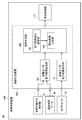
- FIG. It is a block diagram which shows the structure of the vehicle control device of Embodiment 1.
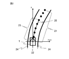
- FIG. It is explanatory drawing of the operation of the bird's-eye view sensor travel path generation part of Embodiment 1.
- FIG. It is a flowchart which shows the operation of the vehicle control device of Embodiment 1. It is a figure explaining the coordinate system of the path of the bird's-eye view sensor travel path generation part and the autonomous sensor travel path generation part of Embodiment 1.
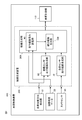
- FIG. It is a block diagram which shows another structure of the vehicle control device of Embodiment 1.
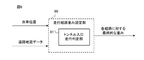
- FIG. It is a block diagram which shows another form of the traveling path weight setting part of Embodiment 1.
- FIG. It is a flowchart which shows the operation of another form of the traveling path weight setting part of Embodiment 1.
- FIG. It is a block diagram which shows another structure of the vehicle control device of Embodiment 1.
- FIG. It is a block diagram which shows another form of the traveling path weight setting part of Embodiment 1.
- FIG. It is a flowchart which shows the operation of another form of the traveling path weight setting part of Embodiment 1.
- It is a block diagram which shows the structure of another form of the vehicle control device of Embodiment 1.
- FIG. It is a block diagram which shows another form of the traveling path weight setting part of Embodiment 1.
- FIG. It is a flowchart which shows the operation of another form of the traveling path weight setting part of Embodiment 1.
- FIG. 1 is a block diagram showing the configuration of the vehicle control device 400 according to the first embodiment.
- the route generation device 300 receives information from the own vehicle position / orientation detection unit 10, the road map data 20, and the camera sensor 30, and outputs information on the integrated route used for controlling the vehicle control unit 110. do.
- the own vehicle position / orientation detection unit 10 outputs the absolute coordinates and orientation of the own vehicle based on the positioning information of the GNSS.
- the road map data 20 includes target point sequence information in the center of the traveling lane around the own vehicle.
- the camera sensor 30 is mounted on the own vehicle and outputs lane marking information of the lane in front of the own vehicle.
- the route generation device 300 includes a bird's-eye view sensor travel route generation unit (first travel route generation unit) 60, an autonomous sensor travel route generation unit (second travel route generation unit) 70, a travel route weight setting unit 90, and an integrated route generation unit.
- the unit 100 is provided.
- the route generation unit 200 is composed of the travel route weight setting unit 90 and the integrated route generation unit 100.
- the bird's-eye view sensor travel route generation unit 60 determines the lane in which the vehicle should travel from the vehicle position / orientation detection unit 10 and the road map data 20 with a specific section in front of the vehicle (referred to as the forward gaze distance) as an approximate range. Outputs the result approximated by a polynomial. That is, as shown in FIG. 2, in the traveling of the own vehicle 1, the own lane 22 restricted by the lane marking information 24 of the road is set, and the specific section in front of the own vehicle 1 is set as the approximation range 23, and this approximation is made. The approximate curve 25 by the polynomial corresponding to the target point sequence information 21 is calculated including the range 23. (See FIG. 2). The forward gaze distance is variable depending on the vehicle speed.
- the autonomous sensor travel route generation unit 70 outputs a result in which the travel route to be traveled by the own vehicle is expressed by a polynomial based on the lane marking information of the front lane by the camera sensor 30.
- the bird's-eye view sensor travel path generation unit 60 and the autonomous sensor travel route generation unit 70 calculate the lateral position deviation, the angle deviation, and the curvature of the route with respect to the own vehicle and the approximate curve as the approximation result by the polynomial, and each of them has a bird's-eye view. Outputs the travel route and autonomous travel route.
- the bird's-eye view sensor travel route is based on the road map data, there is an advantage that the curvature of the route can be expressed more accurately than the autonomous sensor travel route.
- the autonomous sensor travel route is based on the information taken by the camera, the angle between the vehicle and the route and the lateral position of the vehicle and the route can be determined rather than the bird's-eye view sensor travel route that is affected by the position or orientation error due to GNSS. It has the advantage that it can be expressed accurately.
- the "overhead view” represents a state of looking down from a high place, and the “overhead view” represents a state of looking down from a high position.
- the "self-supporting type” represents a state in which various sensors mounted on an automobile such as a camera or sonar are used to recognize and respond to the surroundings.
- the travel route weight setting unit 90 sets weights that are certainty of each travel route of the bird's-eye view sensor travel route generation unit 60 and the autonomous sensor travel route generation unit 70.
- the integrated route generation unit 100 outputs an integrated route that is a single route from the information of the bird's-eye view sensor travel route generation unit 60, the autonomous sensor travel route generation unit 70, and the travel route weight setting unit 90.
- the bird's-eye view sensor travel route generation unit 60 shows the central point sequence of the lane in which the vehicle is currently traveling and the state of the vehicle from the information of the vehicle position / orientation detection unit 10 and the road map data 20. It is calculated as an approximate expression on the own vehicle reference coordinate system shown in 4 and expressed as the equation (1) (step S100).
- the autonomous sensor travel path generation unit 70 approximates the travel path 26 that the vehicle should travel from the lane marking information of the front lane by the camera sensor 30 on the vehicle reference coordinate system of FIG. 4 in the same manner as described above.
- the travel route weight setting unit 90 sets the weight for each travel route calculated in steps S100 and S200, but in the present embodiment, a predetermined value is set (step S400).
- the weight of the bird's-eye view sensor travel route is set higher than the weight of the autonomous sensor travel route, and for the angle component of the vehicle and the route and the lateral position component of the vehicle and the route, the autonomous sensor A predetermined value is set so that the weight of the traveling route is higher than the weight of the bird's-eye view sensor traveling route.
- the weight of the bird's-eye view sensor travel path and the weight of the autonomous sensor travel route are added to be 1, for example, for the curvature component of the route, the weight of the bird's-eye sensor travel route is 0.7, and the weight of the autonomous sensor travel route is 0.7.
- the weight of the autonomous sensor travel route is set to 0.7, and the weight of the bird's-eye sensor travel route is set to 0.3.
- the weight of the bird's-eye sensor travel route is 1, the weight of the autonomous sensor travel route is 0, the angle component of the vehicle and the route, and the lateral position component of the vehicle and the route are the autonomous sensor travel route.
- the weight of the bird's-eye view sensor may be set to 1 and the weight of the bird's-eye view sensor traveling path may be set to 0.
- the weight of the bird's-eye sensor travel route is 1, the weight of the autonomous sensor travel route is 0, the angle component of the vehicle and the route, and the lateral position component of the vehicle and the route are the autonomous sensor travel route.
- the weight of is 1 and the weight of the bird's-eye view sensor travel path is 0, the bird's-eye view sensor travel route is practically used for the curvature component of the route, the angle component between the vehicle and the route, and the lateral position of the vehicle and the route.
- the autonomous sensor travel path will be used.
- the integrated route generation unit 100 uses the coefficients of each route calculated in steps S100 and S200 and the weights for each route set in step S400 to determine the coefficient of the integrated route (equation (3)) that the vehicle should travel. Is calculated by the equations (4) to (6) (step S500).
- the vehicle control unit 110 controls the vehicle using the integrated route (step S600).
- step S600 In the calculation operation of each route in step S100 and step S200, since the calculation result of one does not affect the calculation operation of the other, there is no restriction on the calculation order.
- the weight of the bird's-eye view sensor travel route is higher than the weight of the autonomous sensor travel route for the curvature component of the route.
- the weight of the autonomous sensor travel route is higher than the weight of the bird's-eye sensor travel route, so an integrated route with higher accuracy than before is generated. can.
- the weight of the bird's-eye view sensor traveling path is always higher than the weight of the autonomous sensor traveling path for the curvature component of the path, and the weight of the autonomous sensor traveling path is set for the angle component and the lateral position component.
- the weight is set to be higher than the weight of the bird's-eye view sensor travel path, but the above weighting is performed only in situations where the accuracy of the curvature of the autonomous sensor travel path is low, and in other situations, it is the same as before.
- the vehicle control device has the configuration shown in FIG. 5, the traveling route weight setting unit 90 is shown in FIG.
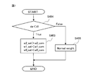
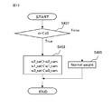
- step S400 whether or not the travel path weight setting unit is shorter than the threshold d1 set by the distance de between the vehicle and the tunnel based on the flowchart of FIG. 7 (the vehicle is near the entrance of the tunnel). Only when it is determined that the vehicle is traveling near the entrance of the tunnel, the weight of the bird's-eye view sensor travel route is set higher than the weight of the autonomous sensor travel route for the curvature component of the route. For the angle component and the lateral position component, the weight of the autonomous sensor traveling path may be higher than the weight of the bird's-eye view sensor traveling path.
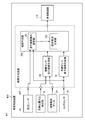
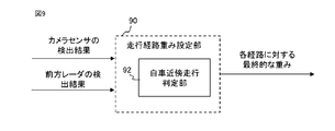
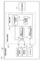
- the vehicle control device 400 is configured to output the detection result by the forward radar 40 and the detection result by the camera sensor 30 to the travel path weight setting unit 90, and the travel path weight setting unit 90 is configured.
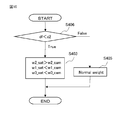
- a vehicle proximity determination unit 92 for determining whether or not a preceding vehicle is traveling within a predetermined distance from the own vehicle is provided, and the preceding vehicle is provided with a predetermined distance from the own vehicle.
- the travel path weight setting unit 90 makes it possible to determine whether or not the vehicle is traveling inside, and the distance df from the own vehicle to the preceding vehicle is shorter than the set threshold value d2 based on the flowchart of FIG.
- the weight of the bird's-eye view sensor travel route is autonomously determined for the curvature component of the route.
- the weight of the sensor travel path may be higher than the weight of the sensor travel path, and the weight of the autonomous sensor travel path may be higher than the weight of the bird's-eye view sensor travel path for the angle component and the lateral position component.
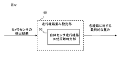
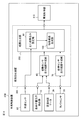
- the vehicle control device 400 is configured as shown in FIG. 11, and the travel route weight setting unit 90 is provided with the autonomous sensor travel route effective distance determination unit 93 as shown in FIG. 12, and the lane marking information of the front lane is obtained from the camera. It is possible to determine whether or not the effective distance (that is, the effective distance of the autonomous sensor travel route) is short, and in step S400, the travel route weight setting unit 90 sets the effective distance of the autonomous sensor travel route based on the flowchart of FIG.
- the weight of the bird's-eye sensor travel path is made higher than the weight of the autonomous sensor travel path for the curvature component of the route, and the angle component.
- the weight of the autonomous sensor travel path may be higher than the weight of the bird's-eye sensor travel path.
- FIG. 14 is a block diagram showing the configuration of the vehicle control device 400 according to the second embodiment.
- the vehicle speed sensor 80 is added to the first embodiment, and the output of the vehicle speed sensor 80 is input to the travel path weight setting unit 90.
- the vehicle speed sensor 80 outputs the vehicle speed of the own vehicle, and the traveling route weight setting unit 90 includes a vehicle speed determination unit 94 as shown in FIG.
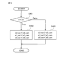
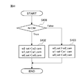
- step S400 the traveling route weight setting unit 90 sets the weight based on the flowchart of FIG. A description will be given below with reference to FIG.
- step S401 it is determined whether or not the vehicle speed V input from the vehicle sensor 50 is lower than the set threshold value V1 (step S401).
- the weight of the autonomous sensor traveling path is made higher than the weight of the bird's-eye sensor traveling path in all of the curvature component, the angle component, and the lateral position component (step S402). ..
- the curvature component is set so that the weight of the bird's-eye view sensor travel path is higher than the weight of the autonomous sensor travel path, and the angle component and the lateral position component are set. Is set so that the weight of the autonomous sensor travel path is higher than the weight of the bird's-eye sensor travel route (step S403).
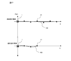
- FIG. 17 is a diagram comparing the output results of the operation of the bird's-eye view sensor traveling route generation unit 60 in the present embodiment under the same conditions as the point sequence information of the road map data, when the vehicle speed of the own vehicle is high and when the vehicle speed is low.
- 1 is the own vehicle.
- Reference numeral 21 denotes target point sequence information of the own vehicle traveling lane, which is included in the road map data 20.
- Reference numeral 101 denotes a bird's-eye view sensor traveling route, which is a traveling route calculated by the bird's-eye view sensor traveling route generation unit 60.
- the bird's-eye view sensor travel path 101 is related to the target route with respect to the vehicle 1 by the absolute coordinates and the absolute orientation of the vehicle 1 output from the vehicle position / orientation detection unit 10 and the target point sequence information 21 of the vehicle lane.
- the weight of the autonomous sensor traveling path is made higher than the weight of the bird's-eye sensor traveling path in all of the curvature component, the angle component, and the lateral position component.
- the weight of the autonomous sensor traveling path is made higher than the weight of the bird's-eye sensor traveling path in all of the curvature component, the angle component, and the lateral position component. It is even better to directly determine whether or not the number of target point sequences of the own vehicle traveling lane used for calculating the approximate curve in the bird's-eye view sensor traveling route generation unit 60 is small.
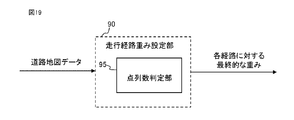
- the vehicle control device 400 is configured as shown in FIG. 18, the travel path weight setting unit 90 is shown in FIG. 19, and the point sequence number determination unit 95 is provided, and the bird's-eye view sensor travel route generation unit 60 calculates an approximate curve.
- step S400 the traveling route weight setting unit is larger than the threshold value N1 set by the number of point rows N based on the flowchart of FIG. It is sufficient to determine whether or not the amount is small, and if it is determined that the amount is small, the weight of the autonomous sensor traveling path may be higher than the weight of the bird's-eye sensor traveling path in all of the curvature component, the angle component, and the lateral position component.
- the bird's-eye view sensor travel path calculated by the bird's-eye view sensor travel route generation unit 60 and the autonomous sensor travel route calculated by the autonomous sensor travel route generation unit 70 are integrated.
- the route is expressed by a quadratic equation composed of the curvature component of the route, the angle component of the vehicle and the route, and the lateral position component of the vehicle and the route as in equations (1) to (6), but it is not always the case.
- the configuration is not limited to the above.
- the curvature change component of the path is expressed by a cubic equation including the third term (Equations (7) to (10)), and the curvature change component of the path is set to the same weight as the curvature component of the path.
- C2_all, C1_all, and C0_all are omitted because they are the same as those in the formulas (4) to (6).
- the travel route generation device 300 is composed of a processor 500 and a storage device 501 as shown in FIG. 21 as an example of hardware. Although the contents of the storage device are not shown, it includes a volatile storage device such as a random access memory and a non-volatile auxiliary storage device such as a flash memory. Further, an auxiliary storage device of a hard disk may be provided instead of the flash memory.
- the processor 500 executes the program input from the storage device 501. In this case, a program is input from the auxiliary storage device to the processor 500 via the volatile storage device. Further, the processor 500 may output data such as a calculation result to the volatile storage device of the storage device 501, or may store the data in the auxiliary storage device via the volatile storage device.
Landscapes
- Engineering & Computer Science (AREA)
- Automation & Control Theory (AREA)
- Transportation (AREA)
- Mechanical Engineering (AREA)
- Human Computer Interaction (AREA)
- Traffic Control Systems (AREA)
- Navigation (AREA)
- Control Of Driving Devices And Active Controlling Of Vehicle (AREA)
Priority Applications (5)
| Application Number | Priority Date | Filing Date | Title |
|---|---|---|---|
| PCT/JP2020/016142 WO2021205656A1 (ja) | 2020-04-10 | 2020-04-10 | 走行経路生成装置 |
| CN202080098986.4A CN115348931A (zh) | 2020-04-10 | 2020-04-10 | 行驶路径生成装置 |
| DE112020007052.2T DE112020007052T5 (de) | 2020-04-10 | 2020-04-10 | Fahrweg-Erzeugungsvorrichtung |
| JP2022514287A JP7378591B2 (ja) | 2020-04-10 | 2020-04-10 | 走行経路生成装置 |
| US17/801,339 US20230079624A1 (en) | 2020-04-10 | 2020-04-10 | Travel path generation device |
Applications Claiming Priority (1)
| Application Number | Priority Date | Filing Date | Title |
|---|---|---|---|
| PCT/JP2020/016142 WO2021205656A1 (ja) | 2020-04-10 | 2020-04-10 | 走行経路生成装置 |
Publications (1)
| Publication Number | Publication Date |
|---|---|
| WO2021205656A1 true WO2021205656A1 (ja) | 2021-10-14 |
Family
ID=78022552
Family Applications (1)
| Application Number | Title | Priority Date | Filing Date |
|---|---|---|---|
| PCT/JP2020/016142 Ceased WO2021205656A1 (ja) | 2020-04-10 | 2020-04-10 | 走行経路生成装置 |
Country Status (5)
| Country | Link |
|---|---|
| US (1) | US20230079624A1 (cg-RX-API-DMAC7.html) |
| JP (1) | JP7378591B2 (cg-RX-API-DMAC7.html) |
| CN (1) | CN115348931A (cg-RX-API-DMAC7.html) |
| DE (1) | DE112020007052T5 (cg-RX-API-DMAC7.html) |
| WO (1) | WO2021205656A1 (cg-RX-API-DMAC7.html) |
Families Citing this family (2)
| Publication number | Priority date | Publication date | Assignee | Title |
|---|---|---|---|---|
| US12311925B2 (en) * | 2020-11-10 | 2025-05-27 | Nec Corporation | Divide-and-conquer for lane-aware diverse trajectory prediction |
| US12240492B2 (en) * | 2022-12-08 | 2025-03-04 | GM Global Technology Operations LLC | Methods and systems for vehicle control under degraded lane perception range |
Citations (5)
| Publication number | Priority date | Publication date | Assignee | Title |
|---|---|---|---|---|
| US20100253489A1 (en) * | 2009-04-02 | 2010-10-07 | Gm Global Technology Operations, Inc. | Distortion and perspective correction of vector projection display |
| JP2016210285A (ja) * | 2015-05-08 | 2016-12-15 | トヨタ自動車株式会社 | 誤認識判定装置 |
| JP2017211193A (ja) * | 2016-05-23 | 2017-11-30 | 本田技研工業株式会社 | 車両位置特定装置、車両制御システム、車両位置特定方法、および車両位置特定プログラム |
| JP2018039285A (ja) * | 2016-09-05 | 2018-03-15 | 株式会社Subaru | 車両の走行制御装置 |
| JP2019043192A (ja) * | 2017-08-30 | 2019-03-22 | マツダ株式会社 | 車両制御装置 |
Family Cites Families (8)
| Publication number | Priority date | Publication date | Assignee | Title |
|---|---|---|---|---|
| US5913376A (en) * | 1995-10-31 | 1999-06-22 | Honda Giken Kogyo Kabushiki Kaisha | Automatic steering control apparatus |
| JP5139939B2 (ja) * | 2008-09-25 | 2013-02-06 | 日立オートモティブシステムズ株式会社 | 車両の減速支援装置 |
| JP6055525B1 (ja) * | 2015-09-02 | 2016-12-27 | 富士重工業株式会社 | 車両の走行制御装置 |
| KR102518532B1 (ko) * | 2016-11-11 | 2023-04-07 | 현대자동차주식회사 | 자율주행차량의 경로 결정장치 및 그 방법 |
| JP6905367B2 (ja) * | 2017-03-21 | 2021-07-21 | 株式会社Subaru | 車両の走行制御装置 |
| CN107702716B (zh) * | 2017-08-31 | 2021-04-13 | 广州小鹏汽车科技有限公司 | 一种无人驾驶路径规划方法、系统和装置 |
| CN108791289B (zh) * | 2018-04-28 | 2021-03-30 | 华为技术有限公司 | 一种车辆控制方法和装置 |
| EP3730384B1 (en) * | 2019-04-24 | 2022-10-26 | Aptiv Technologies Limited | System and method for trajectory estimation |
-
2020
- 2020-04-10 CN CN202080098986.4A patent/CN115348931A/zh active Pending
- 2020-04-10 DE DE112020007052.2T patent/DE112020007052T5/de not_active Withdrawn
- 2020-04-10 WO PCT/JP2020/016142 patent/WO2021205656A1/ja not_active Ceased
- 2020-04-10 JP JP2022514287A patent/JP7378591B2/ja active Active
- 2020-04-10 US US17/801,339 patent/US20230079624A1/en not_active Abandoned
Patent Citations (5)
| Publication number | Priority date | Publication date | Assignee | Title |
|---|---|---|---|---|
| US20100253489A1 (en) * | 2009-04-02 | 2010-10-07 | Gm Global Technology Operations, Inc. | Distortion and perspective correction of vector projection display |
| JP2016210285A (ja) * | 2015-05-08 | 2016-12-15 | トヨタ自動車株式会社 | 誤認識判定装置 |
| JP2017211193A (ja) * | 2016-05-23 | 2017-11-30 | 本田技研工業株式会社 | 車両位置特定装置、車両制御システム、車両位置特定方法、および車両位置特定プログラム |
| JP2018039285A (ja) * | 2016-09-05 | 2018-03-15 | 株式会社Subaru | 車両の走行制御装置 |
| JP2019043192A (ja) * | 2017-08-30 | 2019-03-22 | マツダ株式会社 | 車両制御装置 |
Also Published As
| Publication number | Publication date |
|---|---|
| US20230079624A1 (en) | 2023-03-16 |
| JPWO2021205656A1 (cg-RX-API-DMAC7.html) | 2021-10-14 |
| DE112020007052T5 (de) | 2023-04-13 |
| CN115348931A (zh) | 2022-11-15 |
| JP7378591B2 (ja) | 2023-11-13 |
Similar Documents
| Publication | Publication Date | Title |
|---|---|---|
| US11845471B2 (en) | Travel assistance method and travel assistance device | |
| US11631257B2 (en) | Surroundings recognition device, and surroundings recognition method | |
| US11332141B2 (en) | Path estimation device and path estimation method | |
| US10551509B2 (en) | Methods and systems for vehicle localization | |
| EP4134627B1 (en) | Map information correction method, driving assistance method, and map information correction device | |
| US20180267172A1 (en) | System and method for recognizing position of vehicle | |
| KR102441073B1 (ko) | 자이로 센싱값 보상 장치, 그를 포함한 시스템 및 그 방법 | |
| JP7202982B2 (ja) | 運転支援方法及び運転支援装置 | |
| JP7675359B2 (ja) | 位置推定システム | |
| KR20190047199A (ko) | 주행상황 판단을 위한 지도정보 제공장치, 그를 포함한 시스템 및 그 방법 | |
| US12612067B2 (en) | Autonomous driving control apparatus and method thereof | |
| JP7378591B2 (ja) | 走行経路生成装置 | |
| JP7031748B2 (ja) | 自己位置推定方法及び自己位置推定装置 | |
| JP7399255B2 (ja) | 車両走行経路生成装置、および車両走行経路生成方法 | |
| JP2019066444A (ja) | 位置演算方法、車両制御方法及び位置演算装置 | |
| WO2025019810A1 (en) | Controlling vehicle using static objects and heading angle | |
| US12179760B2 (en) | Vehicle control device, storage medium for storing computer program for vehicle control, and method for controlling vehicle | |
| JP7321034B2 (ja) | 走行支援方法及び走行支援装置 | |
| CN116182841B (zh) | 融合式车辆定位方法与系统 | |
| JPWO2021205656A5 (cg-RX-API-DMAC7.html) | ||
| US12536916B2 (en) | System and method for controlling aerial vehicle | |
| US20260116383A1 (en) | Systems and methods for planning longitudinal paths for future constraints | |
| US20250026354A1 (en) | Controlling vehicle using vehicle curvature and heading angle | |
| WO2025019809A1 (en) | Controlling vehicle using static objects and vehicle curvature | |
| CN120576795A (zh) | 车辆位置更新方法、装置、车辆及存储介质 |
Legal Events
| Date | Code | Title | Description |
|---|---|---|---|
| 121 | Ep: the epo has been informed by wipo that ep was designated in this application |
Ref document number: 20930306 Country of ref document: EP Kind code of ref document: A1 |
|
| ENP | Entry into the national phase |
Ref document number: 2022514287 Country of ref document: JP Kind code of ref document: A |
|
| 122 | Ep: pct application non-entry in european phase |
Ref document number: 20930306 Country of ref document: EP Kind code of ref document: A1 |