WO2021200546A1 - Device for manufacturing electrode plate and method for manufacturing electrode plate - Google Patents
Device for manufacturing electrode plate and method for manufacturing electrode plate Download PDFInfo
- Publication number
- WO2021200546A1 WO2021200546A1 PCT/JP2021/012559 JP2021012559W WO2021200546A1 WO 2021200546 A1 WO2021200546 A1 WO 2021200546A1 JP 2021012559 W JP2021012559 W JP 2021012559W WO 2021200546 A1 WO2021200546 A1 WO 2021200546A1
- Authority
- WO
- WIPO (PCT)
- Prior art keywords
- electrode plate
- tension
- coated
- transport
- compression roll
- Prior art date
Links
- 238000004519 manufacturing process Methods 0.000 title claims abstract description 35
- 238000000034 method Methods 0.000 title description 11
- 230000007246 mechanism Effects 0.000 claims abstract description 82
- 230000006835 compression Effects 0.000 claims abstract description 57
- 238000007906 compression Methods 0.000 claims abstract description 57
- 238000011144 upstream manufacturing Methods 0.000 claims abstract description 27
- 230000007723 transport mechanism Effects 0.000 claims description 44
- 239000000463 material Substances 0.000 claims description 37
- 239000011248 coating agent Substances 0.000 claims description 33
- 238000000576 coating method Methods 0.000 claims description 33
- 239000007772 electrode material Substances 0.000 claims description 26
- 230000009467 reduction Effects 0.000 abstract description 6
- 239000013543 active substance Substances 0.000 abstract 2
- 239000000758 substrate Substances 0.000 abstract 2
- 230000032258 transport Effects 0.000 description 40
- 238000004804 winding Methods 0.000 description 6
- HBBGRARXTFLTSG-UHFFFAOYSA-N Lithium ion Chemical compound [Li+] HBBGRARXTFLTSG-UHFFFAOYSA-N 0.000 description 5
- 239000011888 foil Substances 0.000 description 5
- 229910001416 lithium ion Inorganic materials 0.000 description 5
- 230000037303 wrinkles Effects 0.000 description 5
- 238000013461 design Methods 0.000 description 4
- 238000005259 measurement Methods 0.000 description 4
- 229910052782 aluminium Inorganic materials 0.000 description 3
- XAGFODPZIPBFFR-UHFFFAOYSA-N aluminium Chemical compound [Al] XAGFODPZIPBFFR-UHFFFAOYSA-N 0.000 description 3
- 238000010586 diagram Methods 0.000 description 3
- 230000006870 function Effects 0.000 description 3
- 229910052751 metal Inorganic materials 0.000 description 3
- 239000002184 metal Substances 0.000 description 3
- 239000000203 mixture Substances 0.000 description 3
- 239000002002 slurry Substances 0.000 description 3
- RYGMFSIKBFXOCR-UHFFFAOYSA-N Copper Chemical compound [Cu] RYGMFSIKBFXOCR-UHFFFAOYSA-N 0.000 description 2
- 230000000694 effects Effects 0.000 description 2
- 230000012447 hatching Effects 0.000 description 2
- 230000004048 modification Effects 0.000 description 2
- 238000012986 modification Methods 0.000 description 2
- 230000008569 process Effects 0.000 description 2
- OKTJSMMVPCPJKN-UHFFFAOYSA-N Carbon Chemical compound [C] OKTJSMMVPCPJKN-UHFFFAOYSA-N 0.000 description 1
- 239000011149 active material Substances 0.000 description 1
- 238000007792 addition Methods 0.000 description 1
- 239000012752 auxiliary agent Substances 0.000 description 1
- 239000011230 binding agent Substances 0.000 description 1
- 230000008859 change Effects 0.000 description 1
- 238000006243 chemical reaction Methods 0.000 description 1
- 238000004590 computer program Methods 0.000 description 1
- 238000007796 conventional method Methods 0.000 description 1
- 229910052802 copper Inorganic materials 0.000 description 1
- 239000010949 copper Substances 0.000 description 1
- 239000011889 copper foil Substances 0.000 description 1
- 238000005520 cutting process Methods 0.000 description 1
- 238000012217 deletion Methods 0.000 description 1
- 230000037430 deletion Effects 0.000 description 1
- 239000002270 dispersing agent Substances 0.000 description 1
- 238000011143 downstream manufacturing Methods 0.000 description 1
- 238000001035 drying Methods 0.000 description 1
- 230000014509 gene expression Effects 0.000 description 1
- 239000010439 graphite Substances 0.000 description 1
- 229910002804 graphite Inorganic materials 0.000 description 1
- 238000010438 heat treatment Methods 0.000 description 1
- 229910000625 lithium cobalt oxide Inorganic materials 0.000 description 1
- GELKBWJHTRAYNV-UHFFFAOYSA-K lithium iron phosphate Chemical compound [Li+].[Fe+2].[O-]P([O-])([O-])=O GELKBWJHTRAYNV-UHFFFAOYSA-K 0.000 description 1
- BFZPBUKRYWOWDV-UHFFFAOYSA-N lithium;oxido(oxo)cobalt Chemical compound [Li+].[O-][Co]=O BFZPBUKRYWOWDV-UHFFFAOYSA-N 0.000 description 1
- 238000005096 rolling process Methods 0.000 description 1
- 229910001220 stainless steel Inorganic materials 0.000 description 1
- 239000010935 stainless steel Substances 0.000 description 1
- 238000012546 transfer Methods 0.000 description 1
Images


Classifications
-
- H—ELECTRICITY
- H01—ELECTRIC ELEMENTS
- H01M—PROCESSES OR MEANS, e.g. BATTERIES, FOR THE DIRECT CONVERSION OF CHEMICAL ENERGY INTO ELECTRICAL ENERGY
- H01M4/00—Electrodes
- H01M4/02—Electrodes composed of, or comprising, active material
- H01M4/13—Electrodes for accumulators with non-aqueous electrolyte, e.g. for lithium-accumulators; Processes of manufacture thereof
- H01M4/139—Processes of manufacture
-
- B—PERFORMING OPERATIONS; TRANSPORTING
- B30—PRESSES
- B30B—PRESSES IN GENERAL
- B30B3/00—Presses characterised by the use of rotary pressing members, e.g. rollers, rings, discs
-
- B—PERFORMING OPERATIONS; TRANSPORTING
- B65—CONVEYING; PACKING; STORING; HANDLING THIN OR FILAMENTARY MATERIAL
- B65H—HANDLING THIN OR FILAMENTARY MATERIAL, e.g. SHEETS, WEBS, CABLES
- B65H23/00—Registering, tensioning, smoothing or guiding webs
- B65H23/04—Registering, tensioning, smoothing or guiding webs longitudinally
- B65H23/18—Registering, tensioning, smoothing or guiding webs longitudinally by controlling or regulating the web-advancing mechanism, e.g. mechanism acting on the running web
-
- H—ELECTRICITY
- H01—ELECTRIC ELEMENTS
- H01M—PROCESSES OR MEANS, e.g. BATTERIES, FOR THE DIRECT CONVERSION OF CHEMICAL ENERGY INTO ELECTRICAL ENERGY
- H01M10/00—Secondary cells; Manufacture thereof
- H01M10/04—Construction or manufacture in general
-
- H—ELECTRICITY
- H01—ELECTRIC ELEMENTS
- H01M—PROCESSES OR MEANS, e.g. BATTERIES, FOR THE DIRECT CONVERSION OF CHEMICAL ENERGY INTO ELECTRICAL ENERGY
- H01M10/00—Secondary cells; Manufacture thereof
- H01M10/04—Construction or manufacture in general
- H01M10/0404—Machines for assembling batteries
- H01M10/0409—Machines for assembling batteries for cells with wound electrodes
-
- H—ELECTRICITY
- H01—ELECTRIC ELEMENTS
- H01M—PROCESSES OR MEANS, e.g. BATTERIES, FOR THE DIRECT CONVERSION OF CHEMICAL ENERGY INTO ELECTRICAL ENERGY
- H01M10/00—Secondary cells; Manufacture thereof
- H01M10/05—Accumulators with non-aqueous electrolyte
- H01M10/052—Li-accumulators
-
- H—ELECTRICITY
- H01—ELECTRIC ELEMENTS
- H01M—PROCESSES OR MEANS, e.g. BATTERIES, FOR THE DIRECT CONVERSION OF CHEMICAL ENERGY INTO ELECTRICAL ENERGY
- H01M4/00—Electrodes
- H01M4/02—Electrodes composed of, or comprising, active material
- H01M4/04—Processes of manufacture in general
-
- H—ELECTRICITY
- H01—ELECTRIC ELEMENTS
- H01M—PROCESSES OR MEANS, e.g. BATTERIES, FOR THE DIRECT CONVERSION OF CHEMICAL ENERGY INTO ELECTRICAL ENERGY
- H01M4/00—Electrodes
- H01M4/02—Electrodes composed of, or comprising, active material
- H01M4/04—Processes of manufacture in general
- H01M4/0402—Methods of deposition of the material
- H01M4/0404—Methods of deposition of the material by coating on electrode collectors
-
- H—ELECTRICITY
- H01—ELECTRIC ELEMENTS
- H01M—PROCESSES OR MEANS, e.g. BATTERIES, FOR THE DIRECT CONVERSION OF CHEMICAL ENERGY INTO ELECTRICAL ENERGY
- H01M4/00—Electrodes
- H01M4/02—Electrodes composed of, or comprising, active material
- H01M4/04—Processes of manufacture in general
- H01M4/043—Processes of manufacture in general involving compressing or compaction
- H01M4/0435—Rolling or calendering
-
- Y—GENERAL TAGGING OF NEW TECHNOLOGICAL DEVELOPMENTS; GENERAL TAGGING OF CROSS-SECTIONAL TECHNOLOGIES SPANNING OVER SEVERAL SECTIONS OF THE IPC; TECHNICAL SUBJECTS COVERED BY FORMER USPC CROSS-REFERENCE ART COLLECTIONS [XRACs] AND DIGESTS
- Y02—TECHNOLOGIES OR APPLICATIONS FOR MITIGATION OR ADAPTATION AGAINST CLIMATE CHANGE
- Y02E—REDUCTION OF GREENHOUSE GAS [GHG] EMISSIONS, RELATED TO ENERGY GENERATION, TRANSMISSION OR DISTRIBUTION
- Y02E60/00—Enabling technologies; Technologies with a potential or indirect contribution to GHG emissions mitigation
- Y02E60/10—Energy storage using batteries
Definitions
- the present disclosure relates to an electrode plate manufacturing apparatus and an electrode plate manufacturing method.
- an electrode plate used for a lithium ion secondary battery or the like has a structure in which an electrode active material is coated on the surface of a base material (current collector) made of aluminum foil, copper foil, or the like. Further, the electrode plate has an uncoated portion on which the electrode active material is not coated on the surface of the base material.
- the uncoated portion functions as, for example, a current collecting tab. That is, the electrode plate has a coated portion in which the base material and the electrode active material layer are laminated, and a non-coated portion composed of only the base material.
- the electrode active material is continuously applied to the central portion in the width direction of the base material while transporting a long base material, and extends in the transport direction at the central portion of the base material.
- a method of forming a long electrode plate having a coated portion and an uncoated portion extending in the transport direction at the end portion of the base material is known.
- the coated portion of the electrode plate is compressed by a roll press or the like for the purpose of increasing the density of the electrode active material and making the thickness uniform.
- the electrode plate after compressing the coated portion is wound into a roll and transferred to the next step.
- the electrode plates are separated into a plurality of pieces, laminated with a separator sandwiched between them, and sealed in an outer can.
- the coated portion when the coated portion is compressed, only the electrode active material is compressed and the base material constituting the coated portion is not rolled. However, in reality, when the coated portion is compressed, the base material is also rolled. On the other hand, since the thickness of the uncoated portion is thinner than the thickness of the coated portion, the base material constituting the uncoated portion is not rolled when the coated portion is compressed. As a result, there is a difference between the length of the coated portion and the length of the uncoated portion. If such a variation in length occurs, the electrode plate may be wrinkled, which may hinder the transport and winding of the electrode plate.
- Patent Document 1 an active material coating sheet having a strip-shaped coated portion at the center of the metal foil and a strip-shaped uncoated portion at the edge of the metal foil is placed between pressure rolls. A long sheet electrode is formed through the sheet, and tension is applied to the long sheet electrode while heating the uncoated portion to alleviate the strain between the coated portion and the uncoated portion, and the strain is alleviated. Later, a method of cutting a long sheet electrode and individualizing it into a sheet electrode is disclosed.
- the present inventor provides a process for eliminating the variation in length between the coated portion and the uncoated portion on the transport line, and the electrode plate breaks when the coated portion is compressed. It was found that the risk of doing so increases.
- This disclosure has been made in view of such a situation, and one of the purposes thereof is to provide a technique for manufacturing an electrode plate more stably.
- One aspect of the present disclosure is an electrode plate manufacturing apparatus.
- This device is provided in a transport line of an electrode plate having a coated portion in which the electrode active material is coated on the surface of the base material and an uncoated portion in which the electrode active material is not coated on the surface of the base material, and a transport line.
- a tension reducing mechanism provided on at least one of a compression roll for compressing the coating portion and an upstream section ending with the compression roll and a downstream section starting with the compression roll in the transport line to reduce the tension applied to the electrode plate. , Equipped with.
- Another aspect of the present disclosure is a method for manufacturing an electrode plate.
- an electrode plate having a coated portion in which the electrode active material is coated on the surface of the base material and an uncoated portion in which the electrode active material is not coated on the surface of the base material is conveyed, and the conveyed electrode plate is coated.
- This includes compressing the portions to reduce the tension applied to the electrode plate in at least one of the upstream section ending at the compression position and the downstream section ending at the compression position.
- the electrode plate can be manufactured more stably.
- FIG. 2A is a plan view schematically showing how the transport mechanism transports the electrode plate.
- FIG. 2B is a cross-sectional view schematically showing how the transport mechanism transports the electrode plate. It is a figure which shows the relationship between the dimensional ratio a / b and the tension applied to an electrode plate. It is a schematic diagram of the uncoated portion stretching roll which a stretching mechanism has. It is a figure which shows the relationship between the presence / absence of the 1st tension reduction mechanism and the 2nd tension reduction mechanism, and the elongation rate of a coating part.
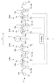
- FIG. 1 is a side view schematically showing the electrode plate manufacturing apparatus according to the embodiment.
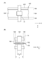
- FIG. 2A is a plan view schematically showing how the transport mechanism transports the electrode plate.
- FIG. 2B is a cross-sectional view schematically showing how the transport mechanism transports the electrode plate.
- the electrode plate manufacturing apparatus 1 includes a transport line 2, a compression roll 4, a tension reducing mechanism 6, and a stretching mechanism 8.
- the tension reducing mechanism 6 and the stretching mechanism 8 are provided on both the upstream side and the downstream side of the compression roll 4 in the transport line 2.
- the tension reducing mechanism 6 on the upstream side will be referred to as a first tension reducing mechanism 6a
- the tension reducing mechanism 6 on the downstream side will be referred to as a second tension reducing mechanism 6b.
- the tension reducing mechanism 6a When it is not necessary to distinguish between the first tension reducing mechanism 6a and the second tension reducing mechanism 6b, these are collectively referred to as the tension reducing mechanism 6.
- the stretching mechanism 8 on the upstream side is referred to as the first stretching mechanism 8a
- the stretching mechanism 8 on the downstream side is referred to as the second stretching mechanism 8b
- the stretching mechanism 8 when it is not necessary to distinguish between the two, they are collectively referred to as the stretching mechanism 8.
- the transport line 2 is a mechanism for transporting the electrode plate 100.
- the electrode plate 100 has a coated portion 104 in which the electrode active material is coated on the surface of the long base material 102, and an uncoated portion 106 in which the electrode active material is not coated on the surface of the base material 102.
- the base material 102 functions as a current collector.
- the base material 102 is made of a foil or a porous body made of, for example, copper or aluminum.
- the base material 102 is made of a foil or a porous body made of, for example, stainless steel or aluminum.
- the electrode active material is graphite or the like when the electrode plate 100 is a negative electrode plate of a lithium ion secondary battery.
- the electrode active material is lithium cobalt oxide, lithium iron phosphate, or the like.
- the electrode active material is applied to the base material 102 in the form of an electrode mixture slurry in which, for example, a conductive auxiliary agent, a binder, a dispersant and the like are mixed.
- the electrode active material layer 108 is formed by drying and rolling the coating film after applying the electrode mixture slurry.
- the electrode active material layers 108 are provided on both sides of the base material 102.
- the coating portion 104 has a structure in which the base material 102 and the electrode active material layer 108 are laminated.
- the uncoated portion 106 is composed of only the base material 102.
- the transport line 2 includes a winding device 10, a winding device 12, and a transport mechanism 14.
- the unwinding device 10 is arranged at the starting point of the transport line 2.
- the unwinding device 10 holds the electrode plate 100 of the coating portion 104 that has not been compressed, for example, in a wound state, and sends the electrode plate 100 to the downstream side of the transport line 2.
- the take-up device 12 is arranged at the end point of the transfer line 2.
- the winding device 12 collects the electrode plate 100 that has been subjected to the compression treatment of the coating portion 104, for example, in the state of a wound body.
- the transport mechanism 14 is arranged between the unwinding device 10 and the winding device 12 on the transport line 2, and transports the electrode plate 100 from the unwinding device 10 toward the winding device 12.
- the transport mechanism 14 of the present embodiment includes a first transport mechanism 14a, a second transport mechanism 14b, a third transport mechanism 14c, and a fourth transport mechanism 14d.
- the first transport mechanism 14a to the fourth transport mechanism 14d are arranged at predetermined intervals in this order from the upstream side in the transport direction A of the electrode plate 100.
- a transport mechanism 14 when it is not necessary to distinguish between the first transport mechanism 14a and the fourth transport mechanism 14d, these are collectively referred to as a transport mechanism 14.
- the number of transport mechanisms 14 is not limited to four.
- the transport mechanism 14 of the present embodiment is composed of a nip roll that grips and transports the electrode plate 100.
- the transport mechanism 14 grips the coating portion 104 and transports the electrode plate 100. Therefore, the transport mechanism 14 does not come into contact with the uncoated portion 106. As a result, it is possible to prevent wrinkles from being generated in the uncoated portion 106 when the electrode plate 100 in which the uncoated portion 106 is stretched more than the coated portion 104 is conveyed by the stretching mechanism 8 described later. Therefore, the structure in which the transport mechanism 14 grips only the coating portion 104 is particularly preferable to be adopted in the second transport mechanism 14b that determines the downstream end of the first stretching mechanism 8a.
- the dimension of the portion of the coating portion 104 gripped by the transport mechanism 14 in the width direction B is defined as a, and the dimension of the coating portion 104 in the width direction B is defined as b. It is designed to satisfy a / b ⁇ 0.4.
- the width direction B is a direction orthogonal to the transport direction A of the electrode plate 100.
- FIG. 3 is a diagram showing the relationship between the dimensional ratio a / b and the tension applied to the electrode plate 100.
- the “tension” on the vertical axis is the ratio of the tension obtained at each a / b to the tension obtained when the transport mechanism 14 grips the entire width of the coating portion 104 (that is, a / b is 1).
- a / b is 0.53 or more.
- the transport mechanism 14 may be configured to suck and transport the electrode plate 100.
- the transport mechanism 14 is composed of a suction roll or the like.
- the dimension a is the dimension in the width direction B of the portion attracted by the transport mechanism 14 in the coating portion 104.
- the transport mechanism 14 may have a plurality of nip rolls or suction rolls arranged in the width direction B. In this case, the total dimension of the portion gripped or sucked by each roll is the dimension a.
- a compression roll 4 is provided between the second transport mechanism 14b and the third transport mechanism 14c in the transport line 2.
- the compression roll 4 is composed of a pair of rolls arranged at predetermined intervals. By passing the electrode plate 100 between the pair of rolls, the coating portion 104 can be pressurized in the thickness direction of the electrode plate 100. As a result, the coating portion 104 is compressed.
- the electrode plate 100 is also conveyed by the rotation of the compression roll 4. Therefore, the compression roll 4 also functions as a nip roll.
- a tension adjusting unit is provided in the section between each nip roll (that is, each transport mechanism 14 and the compression roll 4), and the tension applied to the electrode plate 100 being transported on the transport line 2 is independently adjusted in each section. ..
- the tension adjusting unit of the present embodiment is composed of a dancer roll.
- first tension adjusting unit 16a is provided in the first section R1 between the first transport mechanism 14a and the second transport mechanism 14b.
- a second tension adjusting portion 16b is provided in the second section R2 between the second transport mechanism 14b and the compression roll 4.
- a third tension adjusting portion 16c is provided in the third section R3 between the compression roll 4 and the third transport mechanism 14c.
- a fourth tension adjusting unit 16d is provided in the fourth section R4 between the third transport mechanism 14c and the fourth transport mechanism 14d.
- the first section R1 is provided with a first tension measuring device 18a for measuring the tension applied to the electrode plate 100 by the first tension adjusting unit 16a.
- the second section R2 is provided with a second tension measuring device 18b that measures the tension applied to the electrode plate 100 by the second tension adjusting unit 16b.
- the third section R3 is provided with a third tension measuring device 18c that measures the tension applied to the electrode plate 100 by the third tension adjusting unit 16c.
- a fourth tension measuring device 18d for measuring the tension applied to the electrode plate 100 by the fourth tension adjusting unit 16d is provided. Examples of the first tension measuring device 18a to the fourth tension measuring device 18d include known contact type tension meters and tension pickup rolls.
- the operations of the compression roll 4, the transport mechanism 14, the first tension adjusting unit 16a to the fourth tension adjusting unit 16d, and the like are controlled by the control device 20.
- the control device 20 is realized by elements and circuits such as a computer CPU and memory as a hardware configuration, and is realized by a computer program or the like as a software configuration, but in FIG. 1, it is realized by their cooperation. It is drawn as a functional block. It is well understood by those skilled in the art that this functional block can be realized in various ways by a combination of hardware and software.
- the control device 20 receives tension data from the first tension measuring device 18a to the fourth tension measuring device 18d, and controls the drive of the first tension adjusting unit 16a to the fourth tension adjusting unit 16d based on the received tension data. .. Thereby, the tension applied to the electrode plate 100 in the first section R1 to the fourth section R4 can be adjusted to a desired value.
- the control device 20 can also control the operation of each part based on a preset fixed operation program, instead of feedback control based on the measurement results of the first tension measuring device 18a to the fourth tension measuring device 18d. ..
- a first tension reducing mechanism 6a is provided on the upstream side of the compression roll 4 in the transport line 2.
- the first tension reducing mechanism 6a is arranged in the second section R2 to reduce the tension applied to the electrode plate 100 in the second section R2. That is, the first tension reducing mechanism 6a is arranged in the upstream section of the transport line 2 ending with the compression roll 4.
- the first tension reducing mechanism 6a includes a second tension adjusting unit 16b, a second tension measuring device 18b, a guide roll 21, a control device 20, and the like.
- the tension applied to the electrode plate 100 in the second section R2 is applied to the electrode plate 100 in the first section R1. It is reduced below such tension. For example, the tension applied to the electrode plate 100 in the second section R2 is adjusted to 0.
- a second tension reducing mechanism 6b is provided on the downstream side of the compression roll 4.
- the second tension reducing mechanism 6b is arranged in the third section R3 to reduce the tension applied to the electrode plate 100 in the third section R3. That is, the second tension reducing mechanism 6b is arranged in the downstream section starting from the compression roll 4.
- the second tension reducing mechanism 6b includes a third tension adjusting unit 16c, a third tension measuring device 18c, a guide roll 21, a control device 20, and the like.
- the tension applied to the electrode plate 100 in the third section R3 is applied to the electrode plate 100 in the fourth section R4. It is reduced below such tension. For example, the tension applied to the electrode plate 100 in the third section R3 is adjusted to 0.
- the stretching mechanism 8 is provided at a position farther from the compression roll 4 than the tension reducing mechanism 6 in the transport line 2 to stretch the uncoated portion 106.
- the first stretching mechanism 8a is provided in the first section R1 on the upstream side of the first tension reducing mechanism 6a
- the second stretching is provided in the fourth section R4 on the downstream side of the second tension reducing mechanism 6b.
- a mechanism 8b is provided.
- the first stretching mechanism 8a includes a first tension adjusting unit 16a, a first tension measuring device 18a, a guide roll 21, a control device 20, and the like.
- the second stretching mechanism 8b includes a fourth tension adjusting unit 16d, a fourth tension measuring device 18d, a guide roll 21, a control device 20, and the like.
- the stretching mechanism 8 has an uncoated portion stretching roll 22 shown in FIG. FIG. 4 is a schematic view of the uncoated portion stretching roll 22 included in the stretching mechanism 8.
- the uncoated portion stretching roll 22 has a rotating shaft 24 and a supporting portion 26.
- the rotating shaft 24 rotates as the electrode plate 100 is conveyed.
- the support portion 26 is provided on the outer periphery of the rotary shaft 24 and rotates together with the rotary shaft 24 while supporting the electrode plate 100.
- the support portion 26 has a step and comes into contact with only the uncoated portion 106 of the electrode plate 100.
- the coated portion 104 is separated from the uncoated portion stretching roll 22.
- the uncoated portion 106 When tension is applied to the electrode plate 100 by the first tension adjusting portion 16a or the fourth tension adjusting portion 16d in this state, the uncoated portion 106 is pressed by the support portion 26 and stretched. On the other hand, since the coated portion 104 is not pressed by the support portion 26, the stretching amount is smaller than that of the uncoated portion 106.
- the dancer roll or the guide roll 21 constituting the first tension adjusting portion 16a is composed of the uncoated portion stretching roll 22.
- the dancer roll or the guide roll 21 constituting the fourth tension adjusting portion 16d is composed of the uncoated portion stretching roll 22.
- the guide roll 21 (roll with the load cell) on which the first tension measuring device 18a or the fourth tension measuring device 18d is installed is used as the uncoated portion stretching roll 22. It is preferable not to do so.
- the present inventor when the coating portion 104 is compressed by the compression roll 4 while the electrode plate 100 is under tension, the base material 102 constituting the coating portion 104 is excessively stretched and broken. I found that there are cases.
- the amount of the electrode mixture slurry applied has increased, and the thickness of the electrode active material layer 108 has tended to increase.
- the thickness of the electrode active material layer 108 increases, a larger force is applied to the base material 102 when the coating portion 104 is compressed by the compression roll 4, and the base material 102 is further stretched.
- the tension reducing mechanism 6 is provided on both the upstream side and the downstream side of the compression roll 4, but the tension reduction mechanism 6 is not limited to this and may be provided on at least one of the upstream side and the downstream side of the compression roll 4. For example, it is possible to suppress the stretching of the base material 102 as compared with the case where none of them is provided.
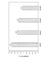
- FIG. 5 is a diagram showing the relationship between the presence / absence of the first tension reducing mechanism 6a and the second tension reducing mechanism 6b and the elongation rate of the coating portion 104.
- a reference example is a manufacturing apparatus provided with neither a first tension reducing mechanism 6a nor a second tension reducing mechanism 6b.
- the first embodiment is a manufacturing apparatus including only the second tension reducing mechanism 6b. That is, it is an example in which the tension caused by the first stretching mechanism 8a is transmitted to the electrode plate 100 from the upstream side of the compression roll 4.
- the second embodiment is a manufacturing apparatus including only the first tension reducing mechanism 6a. That is, it is an example in which the tension caused by the second stretching mechanism 8b is transmitted to the electrode plate 100 from the downstream side of the compression roll 4.
- Example 3 is a manufacturing apparatus including a first tension reducing mechanism 6a and a second tension reducing mechanism 6b. That is, it is an embodiment in which the tension caused by the stretching mechanism 8 is not transmitted to the electrode plate 100 from both the upstream side and the downstream side of the compression roll 4. Further, the manufacturing apparatus of the reference example and each embodiment includes a first stretching mechanism 8a and a second stretching mechanism 8b.
- the "elongation rate of the coated portion" on the vertical axis is the ratio of the length of the coated portion 104 compressed by each manufacturing apparatus to the length of the uncompressed coated portion 104. The elongation rate of the coated portion 104 was obtained by marking lines on the coated portion 104 and the uncoated portion 106 and measuring the length between the lines before and after compression with a metal scale or a magnifying microscope.
- the elongation rate of the coating portion 104 was reduced as compared with the manufacturing apparatus of the reference example. From this, it was confirmed that if the tension reducing mechanism 6 is provided on at least one of the upstream side and the downstream side of the compression roll 4, the stretching of the coating portion 104 can be suppressed, and thus the breakage of the electrode plate 100 can be suppressed. .. Further, from the results of Examples 1 and 2, when the tension reducing mechanism 6 is provided only on either the upstream side or the downstream side of the compression roll 4, it is better to provide the tension reducing mechanism 6 on the upstream side. It was confirmed that the breakage of the plate 100 can be further suppressed.
- Example 3 when the tension reducing mechanism 6 is provided on both the upstream side and the downstream side of the compression roll 4, the elongation of the coating portion 104 can be suppressed most, and thus the breakage of the electrode plate 100 can be suppressed most. It was confirmed that it could be done. Even when the stretching mechanism 8 is not provided on the transport line 2, tension is not a little applied to the electrode plate 100 when the electrode plate 100 is transported. Therefore, even when the stretching mechanism 8 is not provided, the effect of suppressing the breakage of the electrode plate 100 by the tension reducing mechanism 6 can be obtained.
- the manufacturing apparatus 1 for the electrode plate 100 is provided on the transport line 2 for transporting the electrode plate 100 having the coated portion 104 and the uncoated portion 106, and the transport line 2 for coating.
- a tension reduction section at least one of a section extending upstream from the compression roll 4 and a section extending downstream from the compression roll 4, the base material 102 is stretched when the coating portion 104 is compressed by the compression roll 4. Can be suppressed. As a result, the risk of the electrode plate breaking can be reduced, and the electrode plate 100 can be manufactured more stably.
- the tension reducing mechanism 6 of the present embodiment is provided in both the upstream side section and the downstream side section of the compression roll 4. Thereby, the stretching of the base material 102 can be further suppressed. Therefore, the electrode plate 100 can be manufactured more stably.
- the manufacturing apparatus 1 of the present embodiment includes a stretching mechanism 8 that stretches the uncoated portion 106 at a position farther from the compression roll 4 than the tension reducing mechanism 6 in the transport line 2.
- a stretching mechanism 8 that stretches the uncoated portion 106 at a position farther from the compression roll 4 than the tension reducing mechanism 6 in the transport line 2.
- the stretching mechanism 8 of the present embodiment is provided on both the upstream side and the downstream side of the compression roll 4.
- the uncoated portion 106 can be stretched in two steps.
- the transport line 2 of the present embodiment has a transport mechanism 14 that grips or attracts the coating portion 104 to transport the electrode plate 100. As a result, it is possible to suppress the occurrence of wrinkles in the uncoated portion 106, and the electrode plate 100 can be manufactured more stably.
- the dimension of the width direction B orthogonal to the transport direction A of the electrode plate 100 of the portion gripped or attracted by the transport mechanism 14 in the coating portion 104 is a, and the dimension of the coating portion 104 is set to a.
- the dimension of the width direction B is b, a / b ⁇ 0.4 is satisfied. As a result, it is possible to suppress a decrease in the transport speed of the electrode plate 100 while suppressing the occurrence of wrinkles in the uncoated portion 106.
- the present disclosure can be used for an electrode plate manufacturing apparatus and an electrode plate manufacturing method.
Abstract
A device 1 for manufacturing an electrode plate 100 comprises: a conveying line 2 for the electrode plate 100 having a coated section where a surface of a substrate has been coated with an electrode active substance and an uncoated section where the surface of the substrate has not been coated by the electrode active substance; a compression roll 4 which is provided to the conveying line 2 and compresses the coated section; and a tension reduction mechanism 6 which reduces the tension applied to the electrode plate 100, and which is provided to at least one of an upstream side segment having, as a terminal end, the compression roll 4 in the conveying line 2 and a downstream side segment having, as a starting end, the compression roll 4.
Description
本開示は、電極板の製造装置および電極板の製造方法に関する。
The present disclosure relates to an electrode plate manufacturing apparatus and an electrode plate manufacturing method.
一般に、リチウムイオン二次電池等に使用される電極板は、アルミ箔や銅箔等からなる基材(集電体)の表面に電極活物質が塗布された構造を有する。また、電極板は、基材の表面に電極活物質が塗布されていない未塗布部を有する。未塗布部は、例えば集電タブとして機能する。つまり、電極板は、基材および電極活物質層が積層された塗布部と、基材のみからなる未塗布部と、を有する。
Generally, an electrode plate used for a lithium ion secondary battery or the like has a structure in which an electrode active material is coated on the surface of a base material (current collector) made of aluminum foil, copper foil, or the like. Further, the electrode plate has an uncoated portion on which the electrode active material is not coated on the surface of the base material. The uncoated portion functions as, for example, a current collecting tab. That is, the electrode plate has a coated portion in which the base material and the electrode active material layer are laminated, and a non-coated portion composed of only the base material.
このような電極板の製造方法としては、長尺の基材を搬送しながら基材の幅方向における中央部に電極活物質を連続的に塗布して、基材の中央部で搬送方向に延びる塗布部と、基材の端部で搬送方向に延びる未塗布部とを有する長尺の電極板を形成する方法が知られている。また、電極活物質の密度の増加や厚みの均一化等を目的として、電極板の塗布部をロールプレス等で圧縮することが知られている。通常、塗布部を圧縮した後の電極板は、ロール状に巻き取られて次工程に移送される。下流の工程において、電極板は複数に個片化され、セパレータを挟んで積層されて、外装缶に封入される。
As a method for manufacturing such an electrode plate, the electrode active material is continuously applied to the central portion in the width direction of the base material while transporting a long base material, and extends in the transport direction at the central portion of the base material. A method of forming a long electrode plate having a coated portion and an uncoated portion extending in the transport direction at the end portion of the base material is known. Further, it is known that the coated portion of the electrode plate is compressed by a roll press or the like for the purpose of increasing the density of the electrode active material and making the thickness uniform. Normally, the electrode plate after compressing the coated portion is wound into a roll and transferred to the next step. In the downstream process, the electrode plates are separated into a plurality of pieces, laminated with a separator sandwiched between them, and sealed in an outer can.
塗布部を圧縮する際、電極活物質のみが圧縮され、塗布部を構成する基材は圧延されないことが理想的である。しかしながら実際には、塗布部を圧縮すると基材も圧延されてしまう。一方、未塗布部の厚みは塗布部の厚みより薄いため、塗布部の圧縮時に未塗布部を構成する基材は圧延されない。これにより、塗布部の長さと未塗布部の長さとに差が生じてしまう。このような長さのばらつきが生じると、電極板に皺が生じて電極板の搬送や巻き取りに支障が生じ得る。
Ideally, when the coated portion is compressed, only the electrode active material is compressed and the base material constituting the coated portion is not rolled. However, in reality, when the coated portion is compressed, the base material is also rolled. On the other hand, since the thickness of the uncoated portion is thinner than the thickness of the coated portion, the base material constituting the uncoated portion is not rolled when the coated portion is compressed. As a result, there is a difference between the length of the coated portion and the length of the uncoated portion. If such a variation in length occurs, the electrode plate may be wrinkled, which may hinder the transport and winding of the electrode plate.
これに対し、例えば特許文献1には、金属箔の中央部に帯状の塗工部を有し、金属箔の端縁に帯状の未塗工部を有する活物質塗工シートを加圧ロール間に通して長尺シート電極を形成し、未塗工部を加熱しながら長尺シート電極に張力をかけることで塗工部と未塗工部との間の歪みを緩和させ、歪みを緩和した後に長尺シート電極を裁断してシート電極に個片化する方法が開示されている。
On the other hand, for example, in Patent Document 1, an active material coating sheet having a strip-shaped coated portion at the center of the metal foil and a strip-shaped uncoated portion at the edge of the metal foil is placed between pressure rolls. A long sheet electrode is formed through the sheet, and tension is applied to the long sheet electrode while heating the uncoated portion to alleviate the strain between the coated portion and the uncoated portion, and the strain is alleviated. Later, a method of cutting a long sheet electrode and individualizing it into a sheet electrode is disclosed.
本発明者は、上述した従来の方法について鋭意検討した結果、塗布部と未塗布部との長さのばらつきを解消するための処理を搬送ラインに設けると、塗布部の圧縮時に電極板が破断するおそれが高まることを見出した。
As a result of diligent studies on the above-mentioned conventional method, the present inventor provides a process for eliminating the variation in length between the coated portion and the uncoated portion on the transport line, and the electrode plate breaks when the coated portion is compressed. It was found that the risk of doing so increases.
本開示はこうした状況に鑑みてなされたものであり、その目的の1つは、より安定的に電極板を製造する技術を提供することにある。
This disclosure has been made in view of such a situation, and one of the purposes thereof is to provide a technique for manufacturing an electrode plate more stably.
本開示のある態様は、電極板の製造装置である。この装置は、基材の表面に電極活物質が塗布された塗布部および基材の表面に電極活物質が塗布されていない未塗布部を有する電極板の搬送ラインと、搬送ラインに設けられ、塗布部を圧縮する圧縮ロールと、搬送ラインにおける圧縮ロールを終端とする上流側区間および圧縮ロールを始端とする下流側区間の少なくとも一方に設けられ、電極板にかかる張力を低減する張力低減機構と、を備える。
One aspect of the present disclosure is an electrode plate manufacturing apparatus. This device is provided in a transport line of an electrode plate having a coated portion in which the electrode active material is coated on the surface of the base material and an uncoated portion in which the electrode active material is not coated on the surface of the base material, and a transport line. A tension reducing mechanism provided on at least one of a compression roll for compressing the coating portion and an upstream section ending with the compression roll and a downstream section starting with the compression roll in the transport line to reduce the tension applied to the electrode plate. , Equipped with.
本開示の他の態様は、電極板の製造方法である。この方法は、基材の表面に電極活物質が塗布された塗布部および基材の表面に電極活物質が塗布されていない未塗布部を有する電極板を搬送し、搬送される電極板の塗布部を圧縮し、圧縮位置を終端とする上流側区間および圧縮位置を始端とする下流側区間の少なくとも一方において電極板にかかる張力を低減することを含む。
Another aspect of the present disclosure is a method for manufacturing an electrode plate. In this method, an electrode plate having a coated portion in which the electrode active material is coated on the surface of the base material and an uncoated portion in which the electrode active material is not coated on the surface of the base material is conveyed, and the conveyed electrode plate is coated. This includes compressing the portions to reduce the tension applied to the electrode plate in at least one of the upstream section ending at the compression position and the downstream section ending at the compression position.
以上の構成要素の任意の組合せ、本開示の表現を方法、装置、システムなどの間で変換したものもまた、本開示の態様として有効である。
Any combination of the above components and the conversion of the expressions of the present disclosure between methods, devices, systems, etc. are also effective as aspects of the present disclosure.
本開示によれば、より安定的に電極板を製造することができる。
According to the present disclosure, the electrode plate can be manufactured more stably.
以下、本開示を好適な実施の形態をもとに図面を参照しながら説明する。実施の形態は、本開示を限定するものではなく例示であって、実施の形態に記述されるすべての特徴やその組み合わせは、必ずしも本開示の本質的なものであるとは限らない。各図面に示される同一または同等の構成要素、部材、処理には、同一の符号を付するものとし、適宜重複した説明は省略する。また、各図に示す各部の縮尺や形状は、説明を容易にするために便宜的に設定されており、特に言及がない限り限定的に解釈されるものではない。また、本明細書または請求項中に「第1」、「第2」等の用語が用いられる場合には、特に言及がない限りこの用語はいかなる順序や重要度を表すものでもなく、ある構成と他の構成とを区別するためのものである。また、各図面において実施の形態を説明する上で重要ではない部材の一部は省略して表示する。
Hereinafter, the present disclosure will be described based on a preferred embodiment with reference to the drawings. The embodiments are not limited to the present disclosure, but are exemplary, and all features and combinations thereof described in the embodiments are not necessarily essential to the present disclosure. The same or equivalent components, members, and processes shown in the drawings shall be designated by the same reference numerals, and redundant description will be omitted as appropriate. In addition, the scale and shape of each part shown in each figure are set for convenience in order to facilitate explanation, and are not limitedly interpreted unless otherwise specified. In addition, when terms such as "first" and "second" are used in the present specification or claims, these terms do not represent any order or importance unless otherwise specified, and have a certain structure. Is to distinguish between and other configurations. In addition, some of the members that are not important for explaining the embodiment in each drawing are omitted and displayed.
図1は、実施の形態に係る電極板の製造装置を模式的に示す側面図である。図2(A)は、搬送機構が電極板を搬送する様子を模式的に示す平面図である。図2(B)は、搬送機構が電極板を搬送する様子を模式的に示す断面図である。
FIG. 1 is a side view schematically showing the electrode plate manufacturing apparatus according to the embodiment. FIG. 2A is a plan view schematically showing how the transport mechanism transports the electrode plate. FIG. 2B is a cross-sectional view schematically showing how the transport mechanism transports the electrode plate.
電極板の製造装置1は、搬送ライン2と、圧縮ロール4と、張力低減機構6と、延伸機構8と、を備える。本実施の形態の製造装置1では、搬送ライン2における圧縮ロール4の上流側および下流側の両方に、張力低減機構6および延伸機構8が設けられる。以下では、上流側の張力低減機構6を第1張力低減機構6aとし、下流側の張力低減機構6を第2張力低減機構6bとする。また、第1張力低減機構6aと第2張力低減機構6bとを区別する必要がない場合、これらをまとめて張力低減機構6と称する。同様に、上流側の延伸機構8を第1延伸機構8aとし、下流側の延伸機構8を第2延伸機構8bとし、両者を区別する必要がない場合、まとめて延伸機構8と称する。
The electrode plate manufacturing apparatus 1 includes a transport line 2, a compression roll 4, a tension reducing mechanism 6, and a stretching mechanism 8. In the manufacturing apparatus 1 of the present embodiment, the tension reducing mechanism 6 and the stretching mechanism 8 are provided on both the upstream side and the downstream side of the compression roll 4 in the transport line 2. In the following, the tension reducing mechanism 6 on the upstream side will be referred to as a first tension reducing mechanism 6a, and the tension reducing mechanism 6 on the downstream side will be referred to as a second tension reducing mechanism 6b. When it is not necessary to distinguish between the first tension reducing mechanism 6a and the second tension reducing mechanism 6b, these are collectively referred to as the tension reducing mechanism 6. Similarly, the stretching mechanism 8 on the upstream side is referred to as the first stretching mechanism 8a, the stretching mechanism 8 on the downstream side is referred to as the second stretching mechanism 8b, and when it is not necessary to distinguish between the two, they are collectively referred to as the stretching mechanism 8.
搬送ライン2は、電極板100を搬送する機構である。電極板100は、長尺の基材102の表面に電極活物質が塗布された塗布部104と、基材102の表面に電極活物質が塗布されていない未塗布部106と、を有する。基材102は、集電体として機能する。電極板100がリチウムイオン二次電池の負極板である場合、基材102は、例えば銅やアルミニウム等からなる箔や多孔体で構成される。電極板100がリチウムイオン二次電池の正極板である場合、基材102は、例えばステンレス鋼やアルミニウム等からなる箔や多孔体で構成される。
The transport line 2 is a mechanism for transporting the electrode plate 100. The electrode plate 100 has a coated portion 104 in which the electrode active material is coated on the surface of the long base material 102, and an uncoated portion 106 in which the electrode active material is not coated on the surface of the base material 102. The base material 102 functions as a current collector. When the electrode plate 100 is the negative electrode plate of the lithium ion secondary battery, the base material 102 is made of a foil or a porous body made of, for example, copper or aluminum. When the electrode plate 100 is the positive electrode plate of a lithium ion secondary battery, the base material 102 is made of a foil or a porous body made of, for example, stainless steel or aluminum.
電極活物質は、電極板100がリチウムイオン二次電池の負極板である場合、黒鉛等である。電極板100がリチウムイオン二次電池の正極板である場合、電極活物質は、コバルト酸リチウムやリン酸鉄リチウム等である。電極活物質は、例えば導電助剤、結着材、分散剤等を混合した電極合材スラリーの状態で基材102に塗布される。電極合材スラリーを塗布した後に塗膜を乾燥、圧延することで、電極活物質層108が形成される。本実施の形態では、基材102の両面に電極活物質層108が設けられている。塗布部104は、基材102と電極活物質層108とが積層された構造を有する。一方、未塗布部106は、基材102のみからなる。
The electrode active material is graphite or the like when the electrode plate 100 is a negative electrode plate of a lithium ion secondary battery. When the electrode plate 100 is a positive electrode plate of a lithium ion secondary battery, the electrode active material is lithium cobalt oxide, lithium iron phosphate, or the like. The electrode active material is applied to the base material 102 in the form of an electrode mixture slurry in which, for example, a conductive auxiliary agent, a binder, a dispersant and the like are mixed. The electrode active material layer 108 is formed by drying and rolling the coating film after applying the electrode mixture slurry. In the present embodiment, the electrode active material layers 108 are provided on both sides of the base material 102. The coating portion 104 has a structure in which the base material 102 and the electrode active material layer 108 are laminated. On the other hand, the uncoated portion 106 is composed of only the base material 102.
搬送ライン2は、巻き出し装置10と、巻き取り装置12と、搬送機構14と、を有する。巻き出し装置10は、搬送ライン2の開始点に配置される。巻き出し装置10は、塗布部104の圧縮処理が施されていない電極板100を例えば巻回体の状態で保持し、搬送ライン2の下流側に送り出す。巻き取り装置12は、搬送ライン2の終了点に配置される。巻き取り装置12は、塗布部104の圧縮処理が施された電極板100を例えば巻回体の状態で回収する。
The transport line 2 includes a winding device 10, a winding device 12, and a transport mechanism 14. The unwinding device 10 is arranged at the starting point of the transport line 2. The unwinding device 10 holds the electrode plate 100 of the coating portion 104 that has not been compressed, for example, in a wound state, and sends the electrode plate 100 to the downstream side of the transport line 2. The take-up device 12 is arranged at the end point of the transfer line 2. The winding device 12 collects the electrode plate 100 that has been subjected to the compression treatment of the coating portion 104, for example, in the state of a wound body.
搬送機構14は、搬送ライン2上の巻き出し装置10と巻き取り装置12との間に配置され、電極板100を巻き出し装置10から巻き取り装置12に向けて搬送する。本実施の形態の搬送機構14は、第1搬送機構14a、第2搬送機構14b、第3搬送機構14cおよび第4搬送機構14dを含む。第1搬送機構14a~第4搬送機構14dは、電極板100の搬送方向Aにおける上流側から、この順に所定の間隔をあけて配置される。以下では、第1搬送機構14a~第4搬送機構14dを区別する必要がない場合、これらをまとめて搬送機構14と称する。なお、搬送機構14の数は4つに限定されない。
The transport mechanism 14 is arranged between the unwinding device 10 and the winding device 12 on the transport line 2, and transports the electrode plate 100 from the unwinding device 10 toward the winding device 12. The transport mechanism 14 of the present embodiment includes a first transport mechanism 14a, a second transport mechanism 14b, a third transport mechanism 14c, and a fourth transport mechanism 14d. The first transport mechanism 14a to the fourth transport mechanism 14d are arranged at predetermined intervals in this order from the upstream side in the transport direction A of the electrode plate 100. Hereinafter, when it is not necessary to distinguish between the first transport mechanism 14a and the fourth transport mechanism 14d, these are collectively referred to as a transport mechanism 14. The number of transport mechanisms 14 is not limited to four.
本実施の形態の搬送機構14は、電極板100を把持して搬送するニップロールで構成される。搬送機構14は、塗布部104を把持して電極板100を搬送する。したがって、搬送機構14は未塗布部106に当接しない。これにより、後述する延伸機構8によって未塗布部106が塗布部104よりも延伸された状態にある電極板100を搬送する際に、未塗布部106に皺が生じることを抑制できる。したがって、搬送機構14が塗布部104のみを把持する構造は、特に、第1延伸機構8aの下流端を決める第2搬送機構14bに採用されることが好ましい。
The transport mechanism 14 of the present embodiment is composed of a nip roll that grips and transports the electrode plate 100. The transport mechanism 14 grips the coating portion 104 and transports the electrode plate 100. Therefore, the transport mechanism 14 does not come into contact with the uncoated portion 106. As a result, it is possible to prevent wrinkles from being generated in the uncoated portion 106 when the electrode plate 100 in which the uncoated portion 106 is stretched more than the coated portion 104 is conveyed by the stretching mechanism 8 described later. Therefore, the structure in which the transport mechanism 14 grips only the coating portion 104 is particularly preferable to be adopted in the second transport mechanism 14b that determines the downstream end of the first stretching mechanism 8a.
また、図2(B)に示すように、搬送機構14は、塗布部104における搬送機構14で把持される部分の幅方向Bの寸法をa、塗布部104の幅方向Bの寸法をbとするとき、a/b≧0.4を満たすように設計される。幅方向Bは、電極板100の搬送方向Aと直交する方向である。
Further, as shown in FIG. 2B, in the transport mechanism 14, the dimension of the portion of the coating portion 104 gripped by the transport mechanism 14 in the width direction B is defined as a, and the dimension of the coating portion 104 in the width direction B is defined as b. It is designed to satisfy a / b ≧ 0.4. The width direction B is a direction orthogonal to the transport direction A of the electrode plate 100.
図3は、寸法比a/bと電極板100にかかる張力との関係を示す図である。縦軸の「張力」は、搬送機構14が塗布部104の全幅を把持する場合(つまりa/bが1)に得られる張力に対する各a/bで得られる張力の比率である。図3に示すように、a/b=0.4のとき、a/b=1で得られる張力の90%の張力を得ることができる。よって、a/bが0.4以上となるように搬送機構14を設計することで、未塗布部106に皺が生じることを抑制しながら、電極板100の搬送速度が低下することをより確実に抑制できる。また、好ましくはa/bは0.53以上である。
FIG. 3 is a diagram showing the relationship between the dimensional ratio a / b and the tension applied to the electrode plate 100. The “tension” on the vertical axis is the ratio of the tension obtained at each a / b to the tension obtained when the transport mechanism 14 grips the entire width of the coating portion 104 (that is, a / b is 1). As shown in FIG. 3, when a / b = 0.4, a tension of 90% of the tension obtained at a / b = 1 can be obtained. Therefore, by designing the transport mechanism 14 so that a / b is 0.4 or more, it is more certain that the transport speed of the electrode plate 100 is lowered while suppressing the occurrence of wrinkles in the uncoated portion 106. Can be suppressed. Further, preferably, a / b is 0.53 or more.
なお、搬送機構14は、電極板100を吸着して搬送する構成であってもよい。例えば、搬送機構14は、サクションロール等で構成される。この場合、寸法aは、塗布部104における搬送機構14で吸着される部分の幅方向Bの寸法となる。また、搬送機構14は、幅方向Bに配列される複数のニップロールあるいはサクションロールを有してもよい。この場合、各ロールが把持または吸着する部分の寸法の合計が寸法aとなる。
The transport mechanism 14 may be configured to suck and transport the electrode plate 100. For example, the transport mechanism 14 is composed of a suction roll or the like. In this case, the dimension a is the dimension in the width direction B of the portion attracted by the transport mechanism 14 in the coating portion 104. Further, the transport mechanism 14 may have a plurality of nip rolls or suction rolls arranged in the width direction B. In this case, the total dimension of the portion gripped or sucked by each roll is the dimension a.
搬送ライン2における第2搬送機構14bと第3搬送機構14cとの間には、圧縮ロール4が設けられる。圧縮ロール4は、所定の間隔をあけて配置される一対のロールで構成される。電極板100を一対のロールの間に通すことで、電極板100の厚さ方向で塗布部104を加圧することができる。これにより、塗布部104が圧縮される。
A compression roll 4 is provided between the second transport mechanism 14b and the third transport mechanism 14c in the transport line 2. The compression roll 4 is composed of a pair of rolls arranged at predetermined intervals. By passing the electrode plate 100 between the pair of rolls, the coating portion 104 can be pressurized in the thickness direction of the electrode plate 100. As a result, the coating portion 104 is compressed.
圧縮ロール4の回転によっても電極板100は搬送される。このため、圧縮ロール4もニップロールとして機能する。各ニップロール(つまり各搬送機構14および圧縮ロール4)の間の区間には張力調整部が設けられ、搬送ライン2上を搬送中の電極板100にかかる張力は、各区間で独立に調整される。本実施の形態の張力調整部は、ダンサーロールで構成される。
The electrode plate 100 is also conveyed by the rotation of the compression roll 4. Therefore, the compression roll 4 also functions as a nip roll. A tension adjusting unit is provided in the section between each nip roll (that is, each transport mechanism 14 and the compression roll 4), and the tension applied to the electrode plate 100 being transported on the transport line 2 is independently adjusted in each section. .. The tension adjusting unit of the present embodiment is composed of a dancer roll.
具体的には、第1搬送機構14aと第2搬送機構14bとの間の第1区間R1には、第1張力調整部16aが設けられる。第2搬送機構14bと圧縮ロール4との間の第2区間R2には、第2張力調整部16bが設けられる。圧縮ロール4と第3搬送機構14cとの間の第3区間R3には、第3張力調整部16cが設けられる。第3搬送機構14cと第4搬送機構14dとの間の第4区間R4には、第4張力調整部16dが設けられる。
Specifically, the first tension adjusting unit 16a is provided in the first section R1 between the first transport mechanism 14a and the second transport mechanism 14b. A second tension adjusting portion 16b is provided in the second section R2 between the second transport mechanism 14b and the compression roll 4. A third tension adjusting portion 16c is provided in the third section R3 between the compression roll 4 and the third transport mechanism 14c. A fourth tension adjusting unit 16d is provided in the fourth section R4 between the third transport mechanism 14c and the fourth transport mechanism 14d.
第1区間R1には、第1張力調整部16aによって電極板100にかけられる張力を計測する第1張力測定装置18aが設けられる。第2区間R2には、第2張力調整部16bによって電極板100にかけられる張力を計測する第2張力測定装置18bが設けられる。第3区間R3には、第3張力調整部16cによって電極板100にかけられる張力を計測する第3張力測定装置18cが設けられる。第4区間R4には、第4張力調整部16dによって電極板100にかけられる張力を計測する第4張力測定装置18dが設けられる。第1張力測定装置18a~第4張力測定装置18dとしては、公知の接触式張力計やテンションピックアップロール等が例示される。
The first section R1 is provided with a first tension measuring device 18a for measuring the tension applied to the electrode plate 100 by the first tension adjusting unit 16a. The second section R2 is provided with a second tension measuring device 18b that measures the tension applied to the electrode plate 100 by the second tension adjusting unit 16b. The third section R3 is provided with a third tension measuring device 18c that measures the tension applied to the electrode plate 100 by the third tension adjusting unit 16c. In the fourth section R4, a fourth tension measuring device 18d for measuring the tension applied to the electrode plate 100 by the fourth tension adjusting unit 16d is provided. Examples of the first tension measuring device 18a to the fourth tension measuring device 18d include known contact type tension meters and tension pickup rolls.
圧縮ロール4、搬送機構14、第1張力調整部16a~第4張力調整部16d等の動作は、制御装置20によって制御される。制御装置20は、ハードウェア構成としてはコンピュータのCPUやメモリをはじめとする素子や回路で実現され、ソフトウェア構成としてはコンピュータプログラム等によって実現されるが、図1では、それらの連携によって実現される機能ブロックとして描いている。この機能ブロックがハードウェアおよびソフトウェアの組合せによっていろいろなかたちで実現できることは、当業者には当然に理解されるところである。
The operations of the compression roll 4, the transport mechanism 14, the first tension adjusting unit 16a to the fourth tension adjusting unit 16d, and the like are controlled by the control device 20. The control device 20 is realized by elements and circuits such as a computer CPU and memory as a hardware configuration, and is realized by a computer program or the like as a software configuration, but in FIG. 1, it is realized by their cooperation. It is drawn as a functional block. It is well understood by those skilled in the art that this functional block can be realized in various ways by a combination of hardware and software.
制御装置20は、第1張力測定装置18a~第4張力測定装置18dから張力データを受領し、受領した張力データに基づいて第1張力調整部16a~第4張力調整部16dの駆動を制御する。これにより、第1区間R1~第4区間R4において電極板100にかかる張力を所望の値に調整することができる。なお、制御装置20は、第1張力測定装置18a~第4張力測定装置18dの測定結果に基づくフィードバック制御ではなく、予め設定された固定の動作プログラムに基づいて各部の動作を制御することもできる。
The control device 20 receives tension data from the first tension measuring device 18a to the fourth tension measuring device 18d, and controls the drive of the first tension adjusting unit 16a to the fourth tension adjusting unit 16d based on the received tension data. .. Thereby, the tension applied to the electrode plate 100 in the first section R1 to the fourth section R4 can be adjusted to a desired value. The control device 20 can also control the operation of each part based on a preset fixed operation program, instead of feedback control based on the measurement results of the first tension measuring device 18a to the fourth tension measuring device 18d. ..
搬送ライン2における圧縮ロール4の上流側には、第1張力低減機構6aが設けられる。第1張力低減機構6aは、第2区間R2に配置されて、第2区間R2で電極板100にかかる張力を低減する。つまり、第1張力低減機構6aは、搬送ライン2における圧縮ロール4を終端とする上流側区間に配置される。第1張力低減機構6aは、第2張力調整部16b、第2張力測定装置18b、ガイドロール21および制御装置20等で構成される。第2張力測定装置18bの測定結果に基づいて制御装置20が第2張力調整部16bを駆動させることで、第2区間R2で電極板100にかかる張力は、第1区間R1で電極板100にかかる張力よりも低減される。例えば、第2区間R2で電極板100にかかる張力は0に調整される。
A first tension reducing mechanism 6a is provided on the upstream side of the compression roll 4 in the transport line 2. The first tension reducing mechanism 6a is arranged in the second section R2 to reduce the tension applied to the electrode plate 100 in the second section R2. That is, the first tension reducing mechanism 6a is arranged in the upstream section of the transport line 2 ending with the compression roll 4. The first tension reducing mechanism 6a includes a second tension adjusting unit 16b, a second tension measuring device 18b, a guide roll 21, a control device 20, and the like. By driving the second tension adjusting unit 16b by the control device 20 based on the measurement result of the second tension measuring device 18b, the tension applied to the electrode plate 100 in the second section R2 is applied to the electrode plate 100 in the first section R1. It is reduced below such tension. For example, the tension applied to the electrode plate 100 in the second section R2 is adjusted to 0.
また、圧縮ロール4の下流側には、第2張力低減機構6bが設けられる。第2張力低減機構6bは、第3区間R3に配置されて、第3区間R3で電極板100にかかる張力を低減する。つまり、第2張力低減機構6bは、圧縮ロール4を始端とする下流側区間に配置される。第2張力低減機構6bは、第3張力調整部16c、第3張力測定装置18c、ガイドロール21および制御装置20等で構成される。第3張力測定装置18cの測定結果に基づいて制御装置20が第3張力調整部16cを駆動させることで、第3区間R3で電極板100にかかる張力は、第4区間R4で電極板100にかかる張力よりも低減される。例えば、第3区間R3で電極板100にかかる張力は0に調整される。
Further, a second tension reducing mechanism 6b is provided on the downstream side of the compression roll 4. The second tension reducing mechanism 6b is arranged in the third section R3 to reduce the tension applied to the electrode plate 100 in the third section R3. That is, the second tension reducing mechanism 6b is arranged in the downstream section starting from the compression roll 4. The second tension reducing mechanism 6b includes a third tension adjusting unit 16c, a third tension measuring device 18c, a guide roll 21, a control device 20, and the like. By driving the third tension adjusting unit 16c by the control device 20 based on the measurement result of the third tension measuring device 18c, the tension applied to the electrode plate 100 in the third section R3 is applied to the electrode plate 100 in the fourth section R4. It is reduced below such tension. For example, the tension applied to the electrode plate 100 in the third section R3 is adjusted to 0.
延伸機構8は、搬送ライン2における張力低減機構6よりも圧縮ロール4から離れた位置に設けられて、未塗布部106を延伸する。本実施の形態では、第1張力低減機構6aよりも上流側の第1区間R1に第1延伸機構8aが設けられ、第2張力低減機構6bよりも下流側の第4区間R4に第2延伸機構8bが設けられる。第1延伸機構8aは、第1張力調整部16a、第1張力測定装置18a、ガイドロール21および制御装置20等で構成される。第2延伸機構8bは、第4張力調整部16d、第4張力測定装置18d、ガイドロール21および制御装置20等で構成される。
The stretching mechanism 8 is provided at a position farther from the compression roll 4 than the tension reducing mechanism 6 in the transport line 2 to stretch the uncoated portion 106. In the present embodiment, the first stretching mechanism 8a is provided in the first section R1 on the upstream side of the first tension reducing mechanism 6a, and the second stretching is provided in the fourth section R4 on the downstream side of the second tension reducing mechanism 6b. A mechanism 8b is provided. The first stretching mechanism 8a includes a first tension adjusting unit 16a, a first tension measuring device 18a, a guide roll 21, a control device 20, and the like. The second stretching mechanism 8b includes a fourth tension adjusting unit 16d, a fourth tension measuring device 18d, a guide roll 21, a control device 20, and the like.
延伸機構8は、図4に示す未塗布部延伸ロール22を有する。図4は、延伸機構8が有する未塗布部延伸ロール22の模式図である。未塗布部延伸ロール22は、回転軸24と、支持部26と、を有する。回転軸24は、電極板100の搬送にともなって回転する。支持部26は、回転軸24の外周に設けられて、電極板100を支持しながら回転軸24とともに回転する。支持部26は段差を有し、電極板100の未塗布部106のみに当接する。塗布部104は、未塗布部延伸ロール22から離間している。この状態で第1張力調整部16aあるいは第4張力調整部16dによって電極板100に張力がかけられると、未塗布部106は支持部26で押圧されて延伸する。一方、塗布部104は支持部26で押圧されないため、未塗布部106に比べて延伸量は小さい。
The stretching mechanism 8 has an uncoated portion stretching roll 22 shown in FIG. FIG. 4 is a schematic view of the uncoated portion stretching roll 22 included in the stretching mechanism 8. The uncoated portion stretching roll 22 has a rotating shaft 24 and a supporting portion 26. The rotating shaft 24 rotates as the electrode plate 100 is conveyed. The support portion 26 is provided on the outer periphery of the rotary shaft 24 and rotates together with the rotary shaft 24 while supporting the electrode plate 100. The support portion 26 has a step and comes into contact with only the uncoated portion 106 of the electrode plate 100. The coated portion 104 is separated from the uncoated portion stretching roll 22. When tension is applied to the electrode plate 100 by the first tension adjusting portion 16a or the fourth tension adjusting portion 16d in this state, the uncoated portion 106 is pressed by the support portion 26 and stretched. On the other hand, since the coated portion 104 is not pressed by the support portion 26, the stretching amount is smaller than that of the uncoated portion 106.
第1延伸機構8aにおいて、第1張力調整部16aを構成するダンサーロール、あるいはガイドロール21が未塗布部延伸ロール22で構成される。同様に、第2延伸機構8bにおいて、第4張力調整部16dを構成するダンサーロール、あるいはガイドロール21が未塗布部延伸ロール22で構成される。なお、張力の測定精度を維持する観点から、第1張力測定装置18aあるいは第4張力測定装置18dが設置されたガイドロール21(ロードセルが付いているロール)は、未塗布部延伸ロール22として使用しないことが好ましい。
In the first stretching mechanism 8a, the dancer roll or the guide roll 21 constituting the first tension adjusting portion 16a is composed of the uncoated portion stretching roll 22. Similarly, in the second stretching mechanism 8b, the dancer roll or the guide roll 21 constituting the fourth tension adjusting portion 16d is composed of the uncoated portion stretching roll 22. From the viewpoint of maintaining the tension measurement accuracy, the guide roll 21 (roll with the load cell) on which the first tension measuring device 18a or the fourth tension measuring device 18d is installed is used as the uncoated portion stretching roll 22. It is preferable not to do so.
本発明者は、鋭意検討した結果、電極板100に張力をかけた状態で圧縮ロール4で塗布部104を圧縮すると、塗布部104を構成する基材102が過度に延伸して破断してしまう場合があることを見出した。特に、近年は電池のエネルギー密度向上の要請から、電極合材スラリーの塗布量が増え、電極活物質層108の厚みが増す傾向にある。電極活物質層108の厚みが増加すると、圧縮ロール4で塗布部104を圧縮した際に基材102により大きな力がかかり、基材102がより延伸してしまう。
As a result of diligent studies, the present inventor, when the coating portion 104 is compressed by the compression roll 4 while the electrode plate 100 is under tension, the base material 102 constituting the coating portion 104 is excessively stretched and broken. I found that there are cases. In particular, in recent years, due to the demand for improving the energy density of the battery, the amount of the electrode mixture slurry applied has increased, and the thickness of the electrode active material layer 108 has tended to increase. When the thickness of the electrode active material layer 108 increases, a larger force is applied to the base material 102 when the coating portion 104 is compressed by the compression roll 4, and the base material 102 is further stretched.
これに対し、各延伸機構8と圧縮ロール4との間に張力低減機構6を配置することで、各延伸機構8において電極板100にかかる張力が、電極板100の圧縮ロール4で挟まれる部分まで伝わることを抑制できる。これにより、電極板100の圧縮ロール4で挟まれる部分にかかる張力を低減でき、基材102が過度に延伸して破断することを抑制できる。
On the other hand, by arranging the tension reducing mechanism 6 between each stretching mechanism 8 and the compression roll 4, the tension applied to the electrode plate 100 in each stretching mechanism 8 is sandwiched between the compression rolls 4 of the electrode plate 100. Can be suppressed. As a result, the tension applied to the portion of the electrode plate 100 sandwiched between the compression rolls 4 can be reduced, and the base material 102 can be prevented from being excessively stretched and broken.
本実施の形態では、圧縮ロール4の上流側と下流側との両方に張力低減機構6を設けているが、これに限らず圧縮ロール4の上流側および下流側の少なくとも一方に設けられていれば、いずれにも設けられない場合に比べて基材102の延伸を抑制可能である。
In the present embodiment, the tension reducing mechanism 6 is provided on both the upstream side and the downstream side of the compression roll 4, but the tension reduction mechanism 6 is not limited to this and may be provided on at least one of the upstream side and the downstream side of the compression roll 4. For example, it is possible to suppress the stretching of the base material 102 as compared with the case where none of them is provided.
図5は、第1張力低減機構6aおよび第2張力低減機構6bの有無と、塗布部104の伸び率との関係を示す図である。参考例は、第1張力低減機構6aおよび第2張力低減機構6bのいずれも備えない製造装置である。実施例1は、第2張力低減機構6bのみを備える製造装置である。つまり、圧縮ロール4の上流側から第1延伸機構8aに起因する張力が電極板100に伝わる実施例である。実施例2は、第1張力低減機構6aのみを備える製造装置である。つまり、圧縮ロール4の下流側から第2延伸機構8bに起因する張力が電極板100に伝わる実施例である。
FIG. 5 is a diagram showing the relationship between the presence / absence of the first tension reducing mechanism 6a and the second tension reducing mechanism 6b and the elongation rate of the coating portion 104. A reference example is a manufacturing apparatus provided with neither a first tension reducing mechanism 6a nor a second tension reducing mechanism 6b. The first embodiment is a manufacturing apparatus including only the second tension reducing mechanism 6b. That is, it is an example in which the tension caused by the first stretching mechanism 8a is transmitted to the electrode plate 100 from the upstream side of the compression roll 4. The second embodiment is a manufacturing apparatus including only the first tension reducing mechanism 6a. That is, it is an example in which the tension caused by the second stretching mechanism 8b is transmitted to the electrode plate 100 from the downstream side of the compression roll 4.
実施例3は、第1張力低減機構6aおよび第2張力低減機構6bを備える製造装置である。つまり、圧縮ロール4の上流側からも下流側からも延伸機構8に起因する張力が電極板100に伝わらない実施例である。また、参考例および各実施例の製造装置は、第1延伸機構8aおよび第2延伸機構8bを備える。縦軸の「塗布部伸び率」は、未圧縮の塗布部104の長さに対する、各製造装置で圧縮した塗布部104の長さの比率である。塗布部104の伸び率は、塗布部104および未塗布部106に線を罫書き、圧縮前後で線間の長さを金尺や拡大顕微鏡で計測することで得た。
Example 3 is a manufacturing apparatus including a first tension reducing mechanism 6a and a second tension reducing mechanism 6b. That is, it is an embodiment in which the tension caused by the stretching mechanism 8 is not transmitted to the electrode plate 100 from both the upstream side and the downstream side of the compression roll 4. Further, the manufacturing apparatus of the reference example and each embodiment includes a first stretching mechanism 8a and a second stretching mechanism 8b. The "elongation rate of the coated portion" on the vertical axis is the ratio of the length of the coated portion 104 compressed by each manufacturing apparatus to the length of the uncompressed coated portion 104. The elongation rate of the coated portion 104 was obtained by marking lines on the coated portion 104 and the uncoated portion 106 and measuring the length between the lines before and after compression with a metal scale or a magnifying microscope.
図5に示すように、実施例1~3の製造装置では、参考例の製造装置に比べて塗布部104の伸び率が低減した。このことから、張力低減機構6が圧縮ロール4の上流側および下流側の少なくとも一方に設けられていれば、塗布部104の延伸を抑制でき、よって電極板100の破断を抑制できることが確認された。また、実施例1および実施例2の結果から、圧縮ロール4の上流側と下流側のいずれか一方のみに張力低減機構6を設ける場合には、上流側に張力低減機構6を設ける方が電極板100の破断をより抑制できることが確認された。
As shown in FIG. 5, in the manufacturing apparatus of Examples 1 to 3, the elongation rate of the coating portion 104 was reduced as compared with the manufacturing apparatus of the reference example. From this, it was confirmed that if the tension reducing mechanism 6 is provided on at least one of the upstream side and the downstream side of the compression roll 4, the stretching of the coating portion 104 can be suppressed, and thus the breakage of the electrode plate 100 can be suppressed. .. Further, from the results of Examples 1 and 2, when the tension reducing mechanism 6 is provided only on either the upstream side or the downstream side of the compression roll 4, it is better to provide the tension reducing mechanism 6 on the upstream side. It was confirmed that the breakage of the plate 100 can be further suppressed.
また、実施例3の結果から、圧縮ロール4の上流側および下流側の両方に張力低減機構6を設けた場合に、塗布部104の伸びを最も抑制でき、よって電極板100の破断を最も抑制できることが確認された。なお、搬送ライン2に延伸機構8が設けられない場合であっても、電極板100を搬送する際には電極板100に少なからず張力がかかっている。このため、延伸機構8が設けられない場合であっても、張力低減機構6による電極板100の破断抑制効果は得られる。
Further, from the results of Example 3, when the tension reducing mechanism 6 is provided on both the upstream side and the downstream side of the compression roll 4, the elongation of the coating portion 104 can be suppressed most, and thus the breakage of the electrode plate 100 can be suppressed most. It was confirmed that it could be done. Even when the stretching mechanism 8 is not provided on the transport line 2, tension is not a little applied to the electrode plate 100 when the electrode plate 100 is transported. Therefore, even when the stretching mechanism 8 is not provided, the effect of suppressing the breakage of the electrode plate 100 by the tension reducing mechanism 6 can be obtained.
以上説明したように、本実施の形態に係る電極板100の製造装置1は、塗布部104および未塗布部106を有する電極板100を搬送する搬送ライン2と、搬送ライン2に設けられて塗布部104を圧縮する圧縮ロール4と、搬送ライン2における圧縮ロール4を終端とする上流側区間(第2区間R2)および圧縮ロール4を始端とする下流側区間(第3区間R3)の少なくとも一方に設けられて電極板100にかかる張力を低減する張力低減機構6と、を備える。圧縮ロール4から上流側に広がる区間および圧縮ロール4から下流側に広がる区間の少なくとも一方で張力低減区間を設けることで、圧縮ロール4により塗布部104を圧縮した際に基材102が延伸することを抑制することができる。これにより、電極板が破断するおそれを低減でき、より安定的に電極板100を製造することができる。
As described above, the manufacturing apparatus 1 for the electrode plate 100 according to the present embodiment is provided on the transport line 2 for transporting the electrode plate 100 having the coated portion 104 and the uncoated portion 106, and the transport line 2 for coating. At least one of a compression roll 4 that compresses the unit 104, an upstream section (second section R2) that ends at the compression roll 4 in the transport line 2, and a downstream section (third section R3) that starts at the compression roll 4. It is provided with a tension reducing mechanism 6 for reducing the tension applied to the electrode plate 100. By providing a tension reduction section at least one of a section extending upstream from the compression roll 4 and a section extending downstream from the compression roll 4, the base material 102 is stretched when the coating portion 104 is compressed by the compression roll 4. Can be suppressed. As a result, the risk of the electrode plate breaking can be reduced, and the electrode plate 100 can be manufactured more stably.
また、本実施の形態の張力低減機構6は、圧縮ロール4の上流側区間および下流側区間の両方に設けられる。これにより、基材102の延伸をより抑制することができる。よって、より安定的に電極板100を製造することができる。
Further, the tension reducing mechanism 6 of the present embodiment is provided in both the upstream side section and the downstream side section of the compression roll 4. Thereby, the stretching of the base material 102 can be further suppressed. Therefore, the electrode plate 100 can be manufactured more stably.
また、本実施の形態の製造装置1は、搬送ライン2における張力低減機構6よりも圧縮ロール4から離れた位置において、未塗布部106を延伸する延伸機構8を備える。これにより、塗布部104の長さと未塗布部106の長さとのばらつきを低減でき、電極板100に皺が生じることを抑制できる。よって、より安定的に電極板100を製造することができる。
Further, the manufacturing apparatus 1 of the present embodiment includes a stretching mechanism 8 that stretches the uncoated portion 106 at a position farther from the compression roll 4 than the tension reducing mechanism 6 in the transport line 2. As a result, the variation between the length of the coated portion 104 and the length of the uncoated portion 106 can be reduced, and the occurrence of wrinkles on the electrode plate 100 can be suppressed. Therefore, the electrode plate 100 can be manufactured more stably.
また、本実施の形態の延伸機構8は、圧縮ロール4の上流側および下流側の両方に設けられる。これにより、未塗布部106を2段階で延伸することができる。この結果、未塗布部106の延伸処理によって電極板100に歪みが生じたり、電極板100にかかる負荷が大きくなったりすることを抑制できる。よって、より安定的に電極板100を製造することができる。
Further, the stretching mechanism 8 of the present embodiment is provided on both the upstream side and the downstream side of the compression roll 4. As a result, the uncoated portion 106 can be stretched in two steps. As a result, it is possible to prevent the electrode plate 100 from being distorted by the stretching treatment of the uncoated portion 106 and the load applied to the electrode plate 100 from being increased. Therefore, the electrode plate 100 can be manufactured more stably.
また、本実施の形態の搬送ライン2は、塗布部104を把持または吸着して電極板100を搬送する搬送機構14を有する。これにより、未塗布部106に皺が生じることを抑制でき、より安定的に電極板100を製造することができる。
Further, the transport line 2 of the present embodiment has a transport mechanism 14 that grips or attracts the coating portion 104 to transport the electrode plate 100. As a result, it is possible to suppress the occurrence of wrinkles in the uncoated portion 106, and the electrode plate 100 can be manufactured more stably.
また、本実施の形態の製造装置1は、塗布部104における搬送機構14で把持または吸着される部分の、電極板100の搬送方向Aと直交する幅方向Bの寸法をa、塗布部104の幅方向Bの寸法をbとするとき、a/b≧0.4を満たす。これにより、未塗布部106に皺が生じることを抑制しながら、電極板100の搬送速度が低下することを抑制できる。
Further, in the manufacturing apparatus 1 of the present embodiment, the dimension of the width direction B orthogonal to the transport direction A of the electrode plate 100 of the portion gripped or attracted by the transport mechanism 14 in the coating portion 104 is a, and the dimension of the coating portion 104 is set to a. When the dimension of the width direction B is b, a / b ≧ 0.4 is satisfied. As a result, it is possible to suppress a decrease in the transport speed of the electrode plate 100 while suppressing the occurrence of wrinkles in the uncoated portion 106.
以上、本開示の実施の形態について詳細に説明した。前述した実施の形態は、本開示を実施するにあたっての具体例を示したものにすぎない。実施の形態の内容は、本開示の技術的範囲を限定するものではなく、請求の範囲に規定された本開示の思想を逸脱しない範囲において、構成要素の変更、追加、削除等の多くの設計変更が可能である。設計変更が加えられた新たな実施の形態は、組み合わされる実施の形態および変形それぞれの効果をあわせもつ。前述の実施の形態では、このような設計変更が可能な内容に関して、「本実施の形態の」、「本実施の形態では」等の表記を付して強調しているが、そのような表記のない内容でも設計変更が許容される。各実施の形態に含まれる構成要素の任意の組み合わせも、本開示の態様として有効である。図面の断面に付したハッチングは、ハッチングを付した対象の材質を限定するものではない。
The embodiment of the present disclosure has been described in detail above. The above-described embodiment merely shows a specific example in carrying out the present disclosure. The content of the embodiments does not limit the technical scope of the present disclosure, and many designs such as modification, addition, and deletion of components are made without departing from the ideas of the present disclosure defined in the claims. It can be changed. The new embodiment with the design change has the effects of the combined embodiment and the modification. In the above-described embodiment, the contents that can be changed in design are emphasized by adding notations such as "in the present embodiment" and "in the present embodiment". Design changes are allowed even if there is no content. Any combination of components included in each embodiment is also valid as an aspect of the present disclosure. The hatching attached to the cross section of the drawing does not limit the material of the object to which the hatching is attached.
上述した実施の形態に係る発明は、以下に記載する項目によって特定されてもよい。
[項目1]
基材(102)の表面に電極活物質が塗布された塗布部(104)および基材(102)の表面に電極活物質が塗布されていない未塗布部(106)を有する電極板(100)を搬送し、
搬送される電極板(100)の塗布部(104)を圧縮し、
圧縮位置を終端とする上流側区間および圧縮位置を始端とする下流側区間の少なくとも一方において電極板(100)にかかる張力を低減することを含む、
電極板(100)の製造方法。 The invention according to the above-described embodiment may be specified by the items described below.
[Item 1]
An electrode plate (100) having a coated portion (104) in which the electrode active material is coated on the surface of the base material (102) and an uncoated portion (106) in which the electrode active material is not coated on the surface of the base material (102). Transport and
The coated portion (104) of the electrode plate (100) to be conveyed is compressed, and the coating portion (104) is compressed.
This includes reducing the tension applied to the electrode plate (100) in at least one of the upstream section ending at the compression position and the downstream section ending at the compression position.
A method for manufacturing an electrode plate (100).
本開示は、電極板の製造装置および電極板の製造方法に利用することができる。
The present disclosure can be used for an electrode plate manufacturing apparatus and an electrode plate manufacturing method.
1 製造装置、 2 搬送ライン、 4 圧縮ロール、 6 張力低減機構、 8 延伸機構、 14 搬送機構、 100 電極板、 102 基材、 104 塗布部、 106 未塗布部。
1 Manufacturing equipment, 2 Conveyance line, 4 Compression roll, 6 Tension reduction mechanism, 8 Stretching mechanism, 14 Conveyance mechanism, 100 Electrode plate, 102 Base material, 104 Coated part, 106 Unapplied part.
Claims (7)
- 基材の表面に電極活物質が塗布された塗布部および前記表面に前記電極活物質が塗布されていない未塗布部を有する電極板の搬送ラインと、
前記搬送ラインに設けられ、前記塗布部を圧縮する圧縮ロールと、
前記搬送ラインにおける前記圧縮ロールを終端とする上流側区間および前記圧縮ロールを始端とする下流側区間の少なくとも一方に設けられ、前記電極板にかかる張力を低減する張力低減機構と、を備える、
電極板の製造装置。 A transport line for an electrode plate having a coated portion on which the electrode active material is coated on the surface of the base material and an uncoated portion on which the electrode active material is not coated on the surface.
A compression roll provided on the transport line to compress the coating portion, and
A tension reducing mechanism provided in at least one of an upstream section ending the compression roll and a downstream section ending the compression roll in the transport line and reducing the tension applied to the electrode plate is provided.
Electrode plate manufacturing equipment. - 前記張力低減機構は、前記上流側区間および前記下流側区間の両方に設けられる、
請求項1に記載の製造装置。 The tension reducing mechanism is provided in both the upstream section and the downstream section.
The manufacturing apparatus according to claim 1. - 前記搬送ラインにおける前記張力低減機構よりも前記圧縮ロールから離れた位置において、前記未塗布部を延伸する延伸機構を備える、
請求項1または2に記載の製造装置。 A stretching mechanism for stretching the uncoated portion at a position farther from the compression roll than the tension reducing mechanism in the transport line is provided.
The manufacturing apparatus according to claim 1 or 2. - 前記延伸機構は、前記圧縮ロールの上流側および下流側の両方に設けられる、
請求項3に記載の製造装置。 The stretching mechanism is provided on both the upstream side and the downstream side of the compression roll.
The manufacturing apparatus according to claim 3. - 前記搬送ラインは、前記塗布部を把持または吸着して前記電極板を搬送する搬送機構を有する、
請求項3または4に記載の製造装置。 The transport line has a transport mechanism that grips or attracts the coating portion to transport the electrode plate.
The manufacturing apparatus according to claim 3 or 4. - 前記塗布部における前記搬送機構で把持または吸着される部分の、前記電極板の搬送方向と直交する幅方向の寸法をa、前記塗布部の前記幅方向の寸法をbとするとき、
a/b≧0.4を満たす、
請求項5に記載の製造装置。 When the dimension of the portion of the coating portion to be gripped or attracted by the transport mechanism in the width direction orthogonal to the transport direction of the electrode plate is a, and the dimension of the coating portion in the width direction is b.
Satisfy a / b ≧ 0.4,
The manufacturing apparatus according to claim 5. - 基材の表面に電極活物質が塗布された塗布部および前記表面に前記電極活物質が塗布されていない未塗布部を有する電極板を搬送し、
搬送される前記電極板の前記塗布部を圧縮し、
圧縮位置を終端とする上流側区間および圧縮位置を始端とする下流側区間の少なくとも一方において前記電極板にかかる張力を低減することを含む、
電極板の製造方法。 An electrode plate having a coated portion in which the electrode active material is coated on the surface of the base material and an uncoated portion in which the electrode active material is not coated on the surface is conveyed.
The coated portion of the electrode plate to be transported is compressed, and the coating portion is compressed.
This includes reducing the tension applied to the electrode plate in at least one of the upstream section ending at the compression position and the downstream section ending at the compression position.
Manufacturing method of electrode plate.
Priority Applications (2)
| Application Number | Priority Date | Filing Date | Title |
|---|---|---|---|
| US17/915,777 US20230223513A1 (en) | 2020-03-30 | 2021-03-25 | Device for manufacturing electrode plate and method for manufacturing electrode plate |
| CN202180022478.2A CN115315828A (en) | 2020-03-30 | 2021-03-25 | Electrode plate manufacturing device and electrode plate manufacturing method |
Applications Claiming Priority (2)
| Application Number | Priority Date | Filing Date | Title |
|---|---|---|---|
| JP2020059675A JP7165156B2 (en) | 2020-03-30 | 2020-03-30 | Electrode plate manufacturing apparatus and electrode plate manufacturing method |
| JP2020-059675 | 2020-03-30 |
Publications (1)
| Publication Number | Publication Date |
|---|---|
| WO2021200546A1 true WO2021200546A1 (en) | 2021-10-07 |
Family
ID=77919478
Family Applications (1)
| Application Number | Title | Priority Date | Filing Date |
|---|---|---|---|
| PCT/JP2021/012559 WO2021200546A1 (en) | 2020-03-30 | 2021-03-25 | Device for manufacturing electrode plate and method for manufacturing electrode plate |
Country Status (4)
| Country | Link |
|---|---|
| US (1) | US20230223513A1 (en) |
| JP (1) | JP7165156B2 (en) |
| CN (1) | CN115315828A (en) |
| WO (1) | WO2021200546A1 (en) |
Citations (5)
| Publication number | Priority date | Publication date | Assignee | Title |
|---|---|---|---|---|
| JP2014072114A (en) * | 2012-10-01 | 2014-04-21 | Hitachi Power Solutions Co Ltd | Roll press facility for electrode material and manufacturing method of electrode sheet |
| JP2014220113A (en) * | 2013-05-08 | 2014-11-20 | 株式会社日立パワーソリューションズ | Roll press method and roll press facility of electrode material |
| JP2015069747A (en) * | 2013-09-27 | 2015-04-13 | 株式会社日立パワーソリューションズ | Slitter facility for electrode material and electrode material production facility |
| JP2016120503A (en) * | 2014-12-24 | 2016-07-07 | 株式会社日立パワーソリューションズ | Pressure roll and roll press machine therewith |
| JP2018063860A (en) * | 2016-10-13 | 2018-04-19 | 株式会社豊田自動織機 | Rolling press method |
-
2020
- 2020-03-30 JP JP2020059675A patent/JP7165156B2/en active Active
-
2021
- 2021-03-25 WO PCT/JP2021/012559 patent/WO2021200546A1/en active Application Filing
- 2021-03-25 US US17/915,777 patent/US20230223513A1/en active Pending
- 2021-03-25 CN CN202180022478.2A patent/CN115315828A/en active Pending
Patent Citations (5)
| Publication number | Priority date | Publication date | Assignee | Title |
|---|---|---|---|---|
| JP2014072114A (en) * | 2012-10-01 | 2014-04-21 | Hitachi Power Solutions Co Ltd | Roll press facility for electrode material and manufacturing method of electrode sheet |
| JP2014220113A (en) * | 2013-05-08 | 2014-11-20 | 株式会社日立パワーソリューションズ | Roll press method and roll press facility of electrode material |
| JP2015069747A (en) * | 2013-09-27 | 2015-04-13 | 株式会社日立パワーソリューションズ | Slitter facility for electrode material and electrode material production facility |
| JP2016120503A (en) * | 2014-12-24 | 2016-07-07 | 株式会社日立パワーソリューションズ | Pressure roll and roll press machine therewith |
| JP2018063860A (en) * | 2016-10-13 | 2018-04-19 | 株式会社豊田自動織機 | Rolling press method |
Also Published As
| Publication number | Publication date |
|---|---|
| JP7165156B2 (en) | 2022-11-02 |
| JP2021155207A (en) | 2021-10-07 |
| CN115315828A (en) | 2022-11-08 |
| US20230223513A1 (en) | 2023-07-13 |
Similar Documents
| Publication | Publication Date | Title |
|---|---|---|
| US8637189B2 (en) | Battery electrode sheet and manufacturing method therefor | |
| JP5228133B1 (en) | Roll press facility for electrode material and method for producing electrode sheet | |
| US20100330267A1 (en) | Method for producing electrode plate for battery | |
| WO2010082258A1 (en) | Electrode group for nonaqueous battery and method for producing same, and tubular nonaqueous secondary battery and method for manufacturing same | |
| JP5394588B1 (en) | Roll press equipment | |
| WO2020170543A1 (en) | Non-aqueous electrolyte secondary battery, and method for manufacturing positive electrode plate used therein | |
| JP6156070B2 (en) | Battery electrode manufacturing equipment | |
| WO2021200546A1 (en) | Device for manufacturing electrode plate and method for manufacturing electrode plate | |
| JP2014107166A (en) | Manufacturing apparatus of electrode and manufacturing method of electrode | |
| KR102285230B1 (en) | Press apparatus for electrode sheet | |
| KR20210124703A (en) | Apparatus for progressing web used in making electrode of secondary battery | |
| JP7187422B2 (en) | Electrode sheet manufacturing apparatus and electrode sheet manufacturing method | |
| JP2014101221A (en) | Strip carrier device | |
| US20220293911A1 (en) | Roll press apparatus and manufacturing method for compressed strip-shaped electrode plate | |
| JP2016132522A (en) | Diagram printing device and diagram printing method | |
| JP2014102991A (en) | Electrode manufacturing method and electrode manufacturing device | |
| JP6973241B2 (en) | Continuous manufacturing method of membrane electrode gas diffusion layer bonded body | |
| WO2023139860A1 (en) | Stretching and conveying device for green compact | |
| WO2024070092A1 (en) | Manufacturing device for mixture sheet | |
| JP2016004756A (en) | Press device | |
| CN114388728B (en) | Method for manufacturing electrode sheet | |
| JP2005026194A (en) | Cylindrical sealed lead acid storage battery and its manufacturing method | |
| KR102264657B1 (en) | Pressing Apparatus for Electrode Sheet Having Guide Roller | |
| CN115020629B (en) | Rolling device and method for manufacturing compacted strip-shaped electrode plate | |
| CN115084443B (en) | Rolling device and method for manufacturing compacted strip electrode plate |
Legal Events
| Date | Code | Title | Description |
|---|---|---|---|
| 121 | Ep: the epo has been informed by wipo that ep was designated in this application |
Ref document number: 21781726 Country of ref document: EP Kind code of ref document: A1 |
|
| NENP | Non-entry into the national phase |
Ref country code: DE |
|
| 122 | Ep: pct application non-entry in european phase |
Ref document number: 21781726 Country of ref document: EP Kind code of ref document: A1 |