JP6156070B2 - Battery electrode manufacturing equipment - Google Patents
Battery electrode manufacturing equipment Download PDFInfo
- Publication number
- JP6156070B2 JP6156070B2 JP2013230381A JP2013230381A JP6156070B2 JP 6156070 B2 JP6156070 B2 JP 6156070B2 JP 2013230381 A JP2013230381 A JP 2013230381A JP 2013230381 A JP2013230381 A JP 2013230381A JP 6156070 B2 JP6156070 B2 JP 6156070B2
- Authority
- JP
- Japan
- Prior art keywords
- diameter portion
- electrode sheet
- electrode
- region
- width
- Prior art date
- Legal status (The legal status is an assumption and is not a legal conclusion. Google has not performed a legal analysis and makes no representation as to the accuracy of the status listed.)
- Active
Links
Images


Classifications
-
- Y—GENERAL TAGGING OF NEW TECHNOLOGICAL DEVELOPMENTS; GENERAL TAGGING OF CROSS-SECTIONAL TECHNOLOGIES SPANNING OVER SEVERAL SECTIONS OF THE IPC; TECHNICAL SUBJECTS COVERED BY FORMER USPC CROSS-REFERENCE ART COLLECTIONS [XRACs] AND DIGESTS
- Y02—TECHNOLOGIES OR APPLICATIONS FOR MITIGATION OR ADAPTATION AGAINST CLIMATE CHANGE
- Y02E—REDUCTION OF GREENHOUSE GAS [GHG] EMISSIONS, RELATED TO ENERGY GENERATION, TRANSMISSION OR DISTRIBUTION
- Y02E60/00—Enabling technologies; Technologies with a potential or indirect contribution to GHG emissions mitigation
- Y02E60/10—Energy storage using batteries
Description
この発明は、電池に用いられる電極の製造装置に関する。 The present invention relates to an electrode manufacturing apparatus used for a battery.
従来、電池に用いられる電極の製造では、基材の表面に電極材料を塗布し乾燥させて電極シートを作製した後、プレス装置などで電極シートを圧縮することによる電極層の高密度化が図られている。しかしながら、電極層が形成された領域、すなわち、電極材料が塗布された塗布領域の基材は圧縮によって伸びるが、電極層が形成されていない領域、すなわち、電極材料が塗布されていない非塗布領域の基材は圧力が掛からないために伸びず、電極シートに湾曲が生じる。 Conventionally, in the manufacture of electrodes used in batteries, an electrode material is applied to the surface of a substrate and dried to produce an electrode sheet, and then the electrode sheet is compressed by a press device or the like to increase the density of the electrode layer. It has been. However, the region where the electrode layer is formed, that is, the base material of the coated region where the electrode material is applied is stretched by compression, but the region where the electrode layer is not formed, that is, the non-coated region where the electrode material is not coated. The base material does not stretch because no pressure is applied, and the electrode sheet is curved.
そこで、従来から、圧縮後に発生する電極シートの湾曲を抑制する処理が行われている。例えば、特許文献1では、小径部と大径部とを有するガイドローラーの大径部を圧縮後の電極シートの非塗布領域に当接させ、電極シートに掛けられた張力に応じた応力を非塗布領域に集中させて、非塗布領域を伸ばすことにより、電極シートの湾曲を矯正している。
Therefore, conventionally, processing for suppressing the bending of the electrode sheet that occurs after compression has been performed. For example, in
しかしながら、特許文献1では、電極シートの塗工領域が大径部に当接し、塗工領域に対して電極シートに掛けられた張力に応じた応力が加わらないようにするために、非塗工領域と塗工領域の境界領域を含む塗工領域が小径部に対向配置されるように設定されている。このため、境界付近の非塗工領域には大径部に当接せずに伸ばされない部分が生じて、湾曲の矯正が不十分となる、という課題があった。
However, in
本発明は、上述の課題の少なくとも一部を解決するためになされたものであり、以下の形態として実現することが可能である。 SUMMARY An advantage of some aspects of the invention is to solve at least a part of the problems described above, and the invention can be implemented as the following forms.
(1)本発明の一形態によれば、電池用の電極製造装置が提供される。この形態の電池用の電極製造装置は、帯状の基材の表面に長手方向に沿って電極層が塗工された塗工領域と、前記電極層が塗工されていない非塗工領域と、を有する電極シートを、圧縮するプレス部と;前記電極シートの幅方向に沿って小径部および大きい大径部を有する湾曲矯正ローラーであって、前記小径部は前記電極シートの前記塗工領域に対向するとともに、前記大径部は前記電極シートの前記非塗工領域に対向して配置される湾曲矯正ローラーを有し、前記電極シートの前記非塗工領域を前記大径部に当接させて前記電極シートの前記非塗工領域に張力を加えることによって前記電極シートの前記非塗工領域の湾曲を矯正する湾曲矯正部と;を備える。そして、前記電極シートの前記塗工領域と前記非塗工領域との境界が前記湾曲矯正ローラーの前記大径部と前記小径部との境界よりも前記大径部側に位置するように、前記電極シートの幅方向に沿った前記小径部の幅は、前記電極シートの幅方向に沿った前記塗工領域の幅よりも小さく設定されている。この形態の電池用の電極製造装置によれば、課題で説明したような、塗工領域と非塗工領域の境界付近の非塗工領域が湾曲矯正ローラーの大径部に当接されるので、大径部に当接せずに伸ばされない部分が生じず、湾曲が矯正されない部分の残留を抑制することができる。 (1) According to one aspect of the present invention, an electrode manufacturing apparatus for a battery is provided. The electrode manufacturing apparatus for a battery of this form is a coating region where the electrode layer is applied along the longitudinal direction on the surface of the belt-shaped substrate, and a non-coating region where the electrode layer is not applied, A pressing portion for compressing the electrode sheet; and a curl correcting roller having a small diameter portion and a large large diameter portion along the width direction of the electrode sheet, wherein the small diameter portion is in the coating region of the electrode sheet. The large-diameter portion has a curvature correcting roller disposed opposite to the non-coated region of the electrode sheet, and the non-coated region of the electrode sheet is brought into contact with the large-diameter portion. And a curvature correcting part that corrects the curvature of the non-coated area of the electrode sheet by applying tension to the non-coated area of the electrode sheet. And, the boundary between the coating region and the non-coating region of the electrode sheet is located on the large diameter part side of the boundary between the large diameter part and the small diameter part of the curvature correcting roller, The width of the small-diameter portion along the width direction of the electrode sheet is set smaller than the width of the coating region along the width direction of the electrode sheet. According to the battery electrode manufacturing apparatus of this embodiment, as described in the problem, the non-coating region near the boundary between the coating region and the non-coating region is brought into contact with the large diameter portion of the curvature correcting roller. A portion that does not extend without contacting the large-diameter portion does not occur, and the remaining portion where the curvature is not corrected can be suppressed.
なお、本発明は種々の形態で実現することが可能であり、例えば、電池用の電極製造装置の他、電池用の電極の製造方法の形態で実現することができる。 In addition, this invention can be implement | achieved with various forms, for example, can be implement | achieved with the form of the manufacturing method of the electrode for batteries other than the electrode manufacturing apparatus for batteries.
A.第1実施形態:
図1は、第1実施形態としての電極製造装置の構成を示す説明図である。図1(A)は電極製造装置10を上側から見た概略平面を示しており、図1(B)は電極製造装置10を横側から見た概略側面を示している。図中矢印X,Y,Zはそれぞれ互いに直交する3方向を示している。電極製造装置10は、二次電池用の電極、特に、リチウムイオン電池用の電極の製造装置に好適な電極製造装置である。電極製造装置10は、巻出し部100と、塗工部200と、プレス部300と、湾曲矯正部400と、巻取り部500と、を備える。
A. First embodiment:
FIG. 1 is an explanatory diagram showing a configuration of an electrode manufacturing apparatus as the first embodiment. FIG. 1A shows a schematic plan view of the electrode manufacturing apparatus 10 as viewed from above, and FIG. 1B shows a schematic side view of the electrode manufacturing apparatus 10 as viewed from the side. In the figure, arrows X, Y, and Z indicate three directions orthogonal to each other. The electrode manufacturing apparatus 10 is an electrode manufacturing apparatus suitable for an apparatus for manufacturing an electrode for a secondary battery, particularly an electrode for a lithium ion battery. The electrode manufacturing apparatus 10 includes an
塗工部200は、帯状の基材シートの両面(Z方向を向く面)に電極層TLを塗工する装置である。塗工部200は、巻出し部100の巻出しローラー102にセットされた基材シートロールR1から巻き出されて搬送されてくる帯状の基材シートS0の長手方向(X方向)に沿って基材シートS0の両面の中央に電極材料を塗工し、基材シートS0の両面の中央に電極層TLが連続して形成された電極シートS1を作製する。電極シートS1には、電極層TLに対応する領域A1(以下、「塗工領域A1」とも呼ぶ)と、塗工領域A1の外側に電極材料が塗工されずに基材シートが露出した非塗工領域A2と、が形成されている。なお、電極材料の塗工に用いられる塗工機および乾燥機は特に限定されず、種々の塗工機および乾燥機が用いられる。基材シートとしては、例えば、アルミニウム箔、アルミニウム合金箔、銅箔等の種々の帯状金属箔が用いられる。電極材料としては、活物質を含むスラリーやペーストが用いられる。正極の活物質としては、特に限定されるものではなく、種々の酸化物、例えば、リチウムコバルト複合酸化物、リチウムマンガン複合酸化物等が用いられる。負極の活物質も、特に限定されるものではなく、炭素系材料、チタン酸リチウム系材料、酸化物系材料、合金系材料、Li金属系材料等が用いられる。
The
プレス部300は、一対のプレスローラー302a,302bを有している。一対のプレスローラー302a,302bは、電極シートS1を両面(Z方向を向く面)から挟むように配置されている。プレス部300は、不図示のプレスローラー駆動機構によって一対のプレスローラー302a,302bをY方向に沿った軸心を中心に回転させることによって、一対のプレスローラー302a,302bに挟み込まれた電極シートS1を両面から押圧して、基材シートの両面に形成されている電極層TLを圧縮成形する装置である。
The
巻取り部500は、Y方向に沿った軸心を有する巻取りローラー502を備えており、不図示の巻取り駆動機構によって巻取りローラー502を回転させることにより、プレス部300により圧縮成形された電極シートS1をロール状に巻き取って、電極シートロールR2とする装置である。
The
湾曲矯正部400は、2つのガイドロール410,430と、矯正ローラー420と、を備えている。2つのガイドロール410,430は、プレス部300から巻取り部500へ搬送される電極シートS1の鉛直方向(Z方向)の下側を向く面に接し、電極シートS1を支持するように配置される。矯正ローラー420は、上流側のガイドロール410と下流側のガイドロール430との間で、2つのガイドロール410,430に接する電極シートS1の面とは反対側の面に、鉛直方向(Z方向)の上側から接し、電極シートS1を圧接するように配置される。
The
ここで、プレス部300において、一対のプレスローラー302a,302bにより電極シートS1に加えられる圧力は、電極シートS1のうち電極層TLが形成された塗工領域A1にほぼ加わり、非塗工領域A2にはほとんど加わらない。このため、電極シートS1の塗工領域A1では加えられた圧力に応じてその長手方向に沿った伸びが発生するのに対して、電極シートS1の非塗工領域A2ではほとんど伸びが発生せず、塗工領域A1と非塗工領域A2とで伸び差が生じ、この結果、電極シートS1の長手方向および幅方向(長手方向に垂直な方向)に湾曲が発生する。
Here, in the
湾曲矯正部400は、電極シートS1の非塗工領域A2を矯正ローラー420によって長手方向に沿って伸ばすことによって、プレス部300における電極シートS1の圧延によって発生した湾曲を矯正する装置である。
The
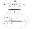
図2は、矯正ローラーを下流側から見た状態で示す説明図である。矯正ローラー420は、径が異なる円柱状の大径部421および小径部422を有している。小径部422は矯正ローラー420の中央部を形成しており、大径部421は矯正ローラー420の両端部を形成している。大径部421の小径部422側の角部421bは面取り加工がなされており、半径rcのR面(丸面)とされている。以下、角部421bを「面取り部421b」とも呼ぶ。また、半径rcを「面取り寸法rc」とも呼ぶ。
FIG. 2 is an explanatory view showing the correction roller as seen from the downstream side. The
矯正ローラー420の小径部422の幅Waは、電極シートS1の塗工領域A1の幅Wbよりも小さく、下式(1)を満たす幅に設定される。
Wa≦Wb−2・rc …(1)
また、矯正ローラー420の大径部421の幅は、矯正ローラー420の幅Wrが電極シートS1の幅Wsよりも大きくして、電極シートS1の非塗工領域A2の外側の端部SLが大径部421の圧接面部421aに接するように設定される。
The width Wa of the
Wa ≦ Wb−2 · rc (1)
Further, the width of the large-
上記式(1)を満たす場合、塗工領域A1と非塗工領域A2の境界BLから端部SLまでの非塗工領域A2の幅方向の全体が矯正ローラー420の大径部421の圧接面部421aによって圧接され、電極シートS1に掛かる張力に応じた応力によって長手方向に伸ばされるため、非塗工領域A2の境界BL付近に、圧接が十分に行われない領域が残留しない。従って、非塗工領域A2の境界BL付近に、湾曲の矯正が十分でない領域が残留することを抑制することが可能である。
When satisfy | filling said Formula (1), the whole width direction of the non-coating area | region A2 from boundary BL of coating area | region A1 and non-coating area | region A2 to edge part SL is the pressure-contact surface part of the
矯正ローラー420の小径部422の幅Waを、上記式(1)を満たす設定とした場合の効果について、以下で説明するように確認した。
The effect when the width Wa of the
厚さ15[μm]で幅Wsが145[mm]の帯状アルミ箔を基材シートとして用い、塗工部200において電極材料を塗工して、厚さ160[μm]の電極シートS1を作製した。電極シートS1の塗工領域A1(電極層TL)の幅Wbは115[μm]とした。電極材料としては、リチウムコバルト複合酸化物を活物質として含むペーストを用いた。プレス部300よりも上流側において電極シートS1に掛かる張力を45[N]、プレス部300よりも下流側において電極シートS1に掛かる張力を100[N]とし、プレス部300において電極シートS1を厚さ160[μm]から厚さ124[μm]に圧延した。この際、塗工領域A1と非塗工領域A2の長手方向の伸び差による湾曲の発生を確認した。なお、これらの各数値条件は一例であって、これらに限定されるものではない。
Using a strip-shaped aluminum foil having a thickness of 15 [μm] and a width Ws of 145 [mm] as a base material sheet, an electrode material is applied in the
上記のように作製された電極シートS1を、小径部422の幅Waの異なる条件の5種類の矯正ローラー420で、それぞれ、湾曲の矯正を行った後の湾曲量を測定することにより、湾曲抑制の効果を確認した。小径部422の幅Waとしては、以下の5種類を選択した。
(1)Wa=116[mm](条件1:Wa>Wb,Wa>Wb−2・rc)
(2)Wa=115[mm](条件2:Wa=Wb,Wa>Wb−2・rc)
(3)Wa=114[mm](条件3:Wa<Wb,Wa<wb−2・rc)
(4)Wa=113[mm](条件4:Wa<Wb,Wa<Wb−2・rc)
(5)Wa=112[mm](条件5:Wa<Wb,Wa<Wb−2・rc)
なお、矯正ローラー420の小径部422の直径φBを100mmとした。そして、矯正ローラー420の大径部421の直径φAを、直径φBより少し大きな寸法、例えば、大径部421の面取り部421の面取り寸法rcの2倍の大きさ分だけ大きい寸法(φB+2・rc)とした。なお、面取り寸法rcは0.3[mm]とした。
Suppression of bending is measured by measuring the amount of bending after correcting the bending of the electrode sheet S1 produced as described above with five types of
(1) Wa = 116 [mm] (Condition 1: Wa> Wb, Wa> Wb-2 · rc)
(2) Wa = 115 [mm] (Condition 2: Wa = Wb, Wa> Wb-2 · rc)
(3) Wa = 114 [mm] (Condition 3: Wa <Wb, Wa <wb-2 · rc)
(4) Wa = 113 [mm] (Condition 4: Wa <Wb, Wa <Wb-2 · rc)
(5) Wa = 112 [mm] (Condition 5: Wa <Wb, Wa <Wb-2 · rc)
The diameter φB of the
図3は、小径部の幅の異なる各矯正ローラーにおける湾曲抑制の評価結果を示す表である。上記式(1)を満たす条件3および条件4では湾曲は0[mm/2m]となった。小径部422の幅Waと塗工領域A1の幅Wbが等しい条件2では、2.0[mm/2m]の湾曲が残留し、小径部422の幅Waが塗工領域A1の幅Wbよりも大きい条件1では、条件2よりも大きい4.0[mm/2m]の湾曲が残留する結果となった。なお、湾曲量[mm/2m]は、長さ2mの電極を平坦な基盤上において、長さ方向の一端に対して他方端が湾曲して変位した量[mm]を測定した値としている。
FIG. 3 is a table showing the evaluation results of curving suppression in each of the correction rollers having different widths of the small diameter portion. Under
条件2では、電極シートS1の非塗工領域A2のうち境界BLの近傍領域において、圧接がされないか圧接が不十分な領域(以下、「圧接が不十分な領域」と呼ぶ)が存在することになり、湾曲の矯正が不十分となって湾曲が残留することになる。そして、条件1では、小径部422の幅Waが塗工領域A1の幅Wbよりも大きく、非塗工領域A2の境界BLの近傍領域において圧接が不十分な領域が条件2の場合よりも広くなるため、湾曲が残留している領域が幅方向に広くなり、条件2の場合よりも湾曲が大きくなっている、と考えられる。条件3および条件4では、非塗工領域A2の端部SLから境界BLまでの全幅について大径部421の圧接面部421aで圧接して、非塗工領域A2の端部SLから境界BLまでの全幅を長手方向に伸ばすことができ、十分に湾曲が矯正されている、と考えられる。
In
なお、条件5においても上記式(1)を満たすが、1.0[mm/2m]の湾曲が残留する結果を示した。これは、小径部422の幅Waが小さくなるほど、塗工領域A1の幅Wbとの差が大きくなることにより、大径部421の圧接面部421aで圧接される塗工領域A1の面積が増加することになり、非塗工領域A2に加わる応力が減少して湾曲の矯正が不十分となるためと考えられる。このことから、小径部422の幅Waと塗工領域A1の幅Wbとの差には許容される上限値がある。上限値としては上記結果から判断して3[mm]未満とすることが好ましく、2.5[mm]未満とすることがより好ましい。
In addition, although the said Formula (1) was satisfy | filled also in the
以上の結果から、本実施形態の矯正ローラー420において、小径部422の幅Waを、上記式(1)を満たす幅とすることにより、電極層TLの圧縮によって発生した湾曲が矯正されることを確認した。従って、本実施形態の電極製造装置10においては、電極シートの非塗工領域に圧接されず伸ばされない領域が残留して湾曲が矯正されない領域が残留することを抑制することが可能である。
From the above results, in the
なお、矯正ローラー420の大径部421の直径φAと、小径部422の直径φBとの差は、0.6[mm](直径φB=100mmに対して0.6%)であり、φAとφBの差はわずかである。そのため、矯正ローラー420は、張力によって変形しないように金属などの剛体で形成されていることが好ましい。
The difference between the diameter φA of the
B.第2実施形態:
図4は、第2実施形態としての電極製造装置の矯正ローラーを下流側から見た状態で示す説明図である。第2実施形態の電極製造装置は、矯正ローラー420Bを除いて第1実施形態の電極製造装置10と同様であるので、以下では、矯正ローラー420Bについてのみ説明する。
B. Second embodiment:
FIG. 4 is an explanatory view showing the straightening roller of the electrode manufacturing apparatus as the second embodiment as seen from the downstream side. Since the electrode manufacturing apparatus of the second embodiment is the same as the electrode manufacturing apparatus 10 of the first embodiment except for the
本実施形態の矯正ローラー420Bは、第1実施形態の矯正ローラー420と同様に、径が異なる円柱状の大径部421Bおよび小径部422を有している。小径部422は矯正ローラー420の中央部を形成しており、大径部421Bは矯正ローラー420Bの両端部を形成している。大径部421Bの小径部422側の角部421Bbは、テーパー幅がwcのテーパー形状となっている。なお、テーパー率1/xについては特に限定はないが、x≧1であることが望ましい。以下、角部421Bbを「テーパー部421Bb」とも呼ぶ。矯正ローラー420Bも、第1実施形態の矯正ローラー420と同様に、金属製で剛性の高い材質を用いて構成されることが好ましい。
Similar to the
矯正ローラー420Bの小径部422の幅Waは、電極シートS1の塗工領域A1の幅Wbよりも小さく、下式(2)を満たす幅に設定される。
Wa≦Wb−2・wc …(2)
また、矯正ローラー420Bの大径部421Bの幅は、電極シートS1の非塗工領域A2の外側の端部SLが大径部421Bの圧接面部421Baに接するように、矯正ローラー420Bの幅Wrが電極シートS1の幅Wsよりも大きく設定される。
The width Wa of the small-
Wa ≦
Further, the width Wr of the
上記式(2)を満たす場合、塗工領域A1と非塗工領域A2の境界BLから端部SLまでの非塗工領域A2の幅方向の全体が矯正ローラー420Bの大径部421Bの圧接面部421Baによって圧接され、電極シートS1に掛かる張力に応じた応力によって長手方向に伸ばされるため、非塗工領域A2の境界BL付近に圧接が十分に行われない領域が残留しない。従って、非塗工領域A2の境界BL付近に、湾曲の矯正が十分でない領域が残留することを抑制することが可能である。
When satisfy | filling said Formula (2), the whole width direction of the non-coating area | region A2 from boundary BL of coating area | region A1 and non-coating area | region A2 to edge part SL is the press-contact surface part of the
矯正ローラー420Bの小径部422の幅Waを、上記式(2)を満たす設定とした場合の効果について、以下で説明するように確認した。
The effect when the width Wa of the
第1実施形態と同様の条件で作製した電極シートS1を、小径部422の幅Waの異なる条件の5種類の矯正ローラー420Bで、それぞれ、湾曲の矯正を行った後の湾曲量を測定することにより、湾曲抑制の効果を確認した。小径部422の幅Waとしては、以下の5種類を選択した。
(1)Wa=115[mm](条件1:Wa=Wb,Wa>Wb−2・wc)
(2)Wa=114[mm](条件2:Wa<Wb,Wa>Wb−2・wc)
(3)Wa=113[mm](条件3:Wa<Wb,Wa=Wb−2・wc)
(4)Wa=112[mm](条件4:Wa<Wb,Wa<Wb−2・wc)
(5)Wa=111[mm](条件5:Wa<Wb,Wa<Wb−2・wc)
なお、大径部421Bのテーパー部421Bbのテーパー幅wcは1.0mmとした。
Measuring the amount of bending after correcting the bending of the electrode sheet S1 produced under the same conditions as in the first embodiment, using the five types of
(1) Wa = 115 [mm] (Condition 1: Wa = Wb, Wa> Wb-2 · wc )
(2) Wa = 114 [mm] (Condition 2: Wa <Wb, Wa> Wb-2 · wc)
(3) Wa = 113 [mm] (Condition 3: Wa <Wb, Wa = Wb−2 · wc )
(4) Wa = 112 [mm] (Condition 4: Wa <Wb, Wa <Wb-2 · wc )
(5) Wa = 111 [mm] (Condition 5: Wa <Wb, Wa <Wb-2 · wc )
The tapered width wc of the tapered portion 421Bb of the
図5は、小径部の幅の異なる各矯正ローラーにおける湾曲抑制の評価結果を示す表である。上記式(2)を満たす条件3および条件4では湾曲は0[mm/2m]となった。小径部422の幅Waが塗工領域A1の幅Wbよりも小さいが、上記式(2)の条件を満たさない条件2では、2.0[mm/2m]の湾曲が残留する結果となった。小径部422の幅Waと塗工領域A1の幅Wbが等しい条件1では、条件2よりも大きい3.0[mm/2m]の湾曲が残留する結果となった。
FIG. 5 is a table showing evaluation results of curving suppression in each of the correction rollers having different widths of the small diameter portion. Under
条件2では、電極シートS1の非塗工領域A2のうち境界BLが大径部421Bのテーパー部形状の面に接するため、非塗工領域A2の境界BLの近傍領域において、圧接が不十分な領域が存在することになり、湾曲の矯正が不十分となって湾曲が残留することになる。そして、条件1では、小径部422の幅Waが塗工領域A1の幅Wbと等しく、非塗工領域A2の境界BLの近傍領域において圧接が不十分な領域が条件2の場合よりも広くなるため、湾曲が残留している領域が広くなり、条件2の場合よりも湾曲が大きくなっている、と考えられる。条件3および条件4では、非塗工領域A2の端部SLから境界BLまでの全幅について大径部421Bの圧接面部421Baで圧接して、非塗工領域A2の端部SLから境界BLまでの全幅を長手方向に伸ばすことができ、十分に湾曲が矯正されている、と考えられる。
In
なお、条件5においても上記式(2)の条件を満たすが、1.0[mm/2m]の湾曲が残留する結果を示した。これは、小径部422の幅Waが小さくなるほど、塗工領域A1の幅Wbとの差が大きくなることにより、大径部421Bの圧接面部421aで圧接される塗工領域A1が増加することになり、非塗工領域A2に加わる応力が減少して湾曲の矯正が不十分となるためと考えられる。このことから、小径部422の幅Waと塗工領域A1の幅Wbとの差には許容される上限値がある。上限値としては上記結果から判断して4[mm]未満とすることが好ましく、3.5[mm]未満とすることがより好ましい。
In
以上の結果から、本実施形態の矯正ローラー420Bにおいて、小径部422の幅Waを、上記式(2)を満たすこと幅とすることにより、電極層TLの圧縮によって発生した湾曲が矯正されることを確認した。従って、本実施形態においても、第1実施形態と同様に、電極シートの非塗工領域に圧接されず伸ばされない領域が残留して湾曲が矯正されない領域が残留することを抑制することが可能である。
From the above results, in the
なお、上記式(2)を満たす小径部422の幅Waを有する矯正ローラー420Bとした場合の効果の確認において、設定した各数値は一例であって、それらに限定されるものではなく、上記式(2)を満たす種々の条件で適用可能である。
In the confirmation of the effect when the
C.変形例:
上記実施形態では、塗工部とプレス部と湾曲矯正部とを備える電極製造装置を例に説明したが、塗工部を省略し、巻出し部から巻き出されて搬送されてくる帯状の電極シートをプレス部で圧延し、湾曲矯正部で湾曲を矯正する電極製造装置としてもよい。
C. Variations:
In the above embodiment, the electrode manufacturing apparatus including the coating unit, the press unit, and the curvature correcting unit has been described as an example. However, the coating unit is omitted, and the strip-shaped electrode is unwound from the unwinding unit and conveyed. It is good also as an electrode manufacturing apparatus which rolls a sheet | seat with a press part, and correct | amends curvature by a curvature correction part.
また、上記各実施形態では、1つの矯正ローラーを配置する構成を例に説明したが、複数の矯正ローラーを配置する構成としてもよい。 Moreover, in each said embodiment, although the structure which arrange | positions one correction roller was demonstrated to the example, it is good also as a structure which arrange | positions a some correction roller.
本発明は、上述の実施形態や実施例、変形例に限られるものではなく、その趣旨を逸脱しない範囲において種々の構成で実現することができる。例えば、発明の概要の欄に記載した各形態中の技術的特徴に対応する実施形態、実施例、変形例中の技術的特徴は、上述の課題の一部又は全部を解決するために、あるいは、上述の効果の一部又は全部を達成するために、適宜、差し替えや、組み合わせを行うことが可能である。また、前述した実施形態および各変形例における構成要素の中の、独立請求項で記載された要素以外の要素は、付加的な要素であり、適宜省略可能である。 The present invention is not limited to the above-described embodiments, examples, and modifications, and can be realized with various configurations without departing from the spirit thereof. For example, the technical features in the embodiments, examples, and modifications corresponding to the technical features in each embodiment described in the summary section of the invention are to solve some or all of the above-described problems, or In order to achieve part or all of the above effects, replacement or combination can be performed as appropriate. Moreover, elements other than the elements described in the independent claims among the constituent elements in the above-described embodiments and modifications are additional elements and can be omitted as appropriate.
10…電極製造装置
100…巻出し部
102…巻出しローラー
200…塗工部
300…プレス部
302a,302b…プレスローラー
400…湾曲矯正部
410,430…ガイドロール
420…矯正ローラー
420B…矯正ローラー
421…大径部
421B…大径部
421a…圧接面部
421b…角部(面取り部)
421Ba…圧接面部
421Bb…角部(テーパー部)
422…小径部
500…巻取り部
502…巻取りローラー
S0…基材シート
S1…電極シート
A1…塗工領域
A2…非塗工領域
TL…電極層
BL…境界
SL…端部
R1…基材シートロール
R2…電極シートロール
DESCRIPTION OF SYMBOLS 10 ...
421Ba: Pressure contact surface portion 421Bb: Corner portion (tapered portion)
422 ...
Claims (1)
帯状の基材の表面の幅方向の中央部に長手方向に沿って電極層が塗工された塗工領域と、前記塗工領域の前記幅方向の両側に前記電極層が塗工されていない非塗工領域と、を有する電極シートを、圧縮するプレス部と、
前記電極シートの幅方向に沿って小径部および前記小径部よりも大きい外径の大径部を有する湾曲矯正ローラーであって、前記小径部は前記電極シートの前記塗工領域に対向するとともに、前記大径部は前記電極シートの前記非塗工領域に対向して配置される湾曲矯正ローラーを有し、前記電極シートの前記非塗工領域を前記大径部に当接させて前記電極シートの前記非塗工領域に張力を加えることによって前記電極シートの前記非塗工領域の湾曲を矯正する湾曲矯正部と、
を備え、
前記電極シートの前記塗工領域と前記非塗工領域との境界が前記大径部の圧接面部に接するように、前記小径部の両側の前記大径部の前記圧接面部の間隔が、前記電極シートの幅方向に沿った前記塗工領域の幅以下に設定されている、電池用の電極製造装置。 An electrode manufacturing apparatus for a battery,
A coating region in which an electrode layer is applied along the longitudinal direction in the center in the width direction of the surface of the band-shaped substrate, and the electrode layer is not applied on both sides of the coating region in the width direction An electrode sheet having a non-coating region, and a pressing unit that compresses the electrode sheet,
A curvature correcting roller having a small diameter portion and a large diameter portion having an outer diameter larger than the small diameter portion along the width direction of the electrode sheet, the small diameter portion facing the coating region of the electrode sheet, The large-diameter portion has a curvature correcting roller arranged to face the non-coated region of the electrode sheet, and the electrode sheet is brought into contact with the non-coated region of the electrode sheet. A curvature correcting part for correcting the curvature of the non-coated area of the electrode sheet by applying a tension to the non-coated area;
With
The distance between the pressure contact surface portions of the large diameter portion on both sides of the small diameter portion is such that the boundary between the coating region and the non-coating region of the electrode sheet is in contact with the pressure contact surface portion of the large diameter portion. An electrode manufacturing apparatus for a battery, which is set to be equal to or smaller than the width of the coating region along the width direction of the sheet.
Priority Applications (1)
| Application Number | Priority Date | Filing Date | Title |
|---|---|---|---|
| JP2013230381A JP6156070B2 (en) | 2013-11-06 | 2013-11-06 | Battery electrode manufacturing equipment |
Applications Claiming Priority (1)
| Application Number | Priority Date | Filing Date | Title |
|---|---|---|---|
| JP2013230381A JP6156070B2 (en) | 2013-11-06 | 2013-11-06 | Battery electrode manufacturing equipment |
Publications (3)
| Publication Number | Publication Date |
|---|---|
| JP2015090805A JP2015090805A (en) | 2015-05-11 |
| JP2015090805A5 JP2015090805A5 (en) | 2016-08-12 |
| JP6156070B2 true JP6156070B2 (en) | 2017-07-05 |
Family
ID=53194233
Family Applications (1)
| Application Number | Title | Priority Date | Filing Date |
|---|---|---|---|
| JP2013230381A Active JP6156070B2 (en) | 2013-11-06 | 2013-11-06 | Battery electrode manufacturing equipment |
Country Status (1)
| Country | Link |
|---|---|
| JP (1) | JP6156070B2 (en) |
Families Citing this family (7)
| Publication number | Priority date | Publication date | Assignee | Title |
|---|---|---|---|---|
| JP6672706B2 (en) * | 2015-10-30 | 2020-03-25 | 三洋電機株式会社 | Method for manufacturing electrode plate and method for manufacturing secondary battery |
| JP7041886B2 (en) * | 2017-11-29 | 2022-03-25 | 大野ロール株式会社 | Roll press machine with wrinkle prevention device and roll press method |
| US20220140308A1 (en) | 2019-02-19 | 2022-05-05 | Sanyo Electric Co., Ltd. | Non-aqueous electrolyte secondary battery, and method for manufacturing positive electrode plate used therein |
| JP7413900B2 (en) | 2020-04-02 | 2024-01-16 | トヨタ自動車株式会社 | Electrode plate manufacturing method |
| JP7322796B2 (en) * | 2020-04-24 | 2023-08-08 | トヨタ自動車株式会社 | METHOD AND SYSTEM FOR MANUFACTURING COMPRESSED STRIP ELECTRODE PLATE |
| JP7221918B2 (en) * | 2020-10-02 | 2023-02-14 | プライムプラネットエナジー&ソリューションズ株式会社 | Electrode sheet manufacturing method |
| KR20230166902A (en) * | 2022-05-31 | 2023-12-07 | 주식회사 엘지에너지솔루션 | Rolling roll and electrode rolling apparatus comprising the same |
Family Cites Families (1)
| Publication number | Priority date | Publication date | Assignee | Title |
|---|---|---|---|---|
| JP2003100286A (en) * | 2001-09-19 | 2003-04-04 | Toyota Motor Corp | Method and apparatus for manufacturing strip electrode |
-
2013
- 2013-11-06 JP JP2013230381A patent/JP6156070B2/en active Active
Also Published As
| Publication number | Publication date |
|---|---|
| JP2015090805A (en) | 2015-05-11 |
Similar Documents
| Publication | Publication Date | Title |
|---|---|---|
| JP6156070B2 (en) | Battery electrode manufacturing equipment | |
| KR101765773B1 (en) | Electrode sheet for battery and method of manufacturing the same | |
| JP5760366B2 (en) | Method for pressing battery electrode foil | |
| US20100330267A1 (en) | Method for producing electrode plate for battery | |
| JP5228133B1 (en) | Roll press facility for electrode material and method for producing electrode sheet | |
| JP5394588B1 (en) | Roll press equipment | |
| JP2012501052A5 (en) | ||
| JP2014116141A (en) | Method of manufacturing strip electrode | |
| US20220140308A1 (en) | Non-aqueous electrolyte secondary battery, and method for manufacturing positive electrode plate used therein | |
| JP6658496B2 (en) | Electrode plate manufacturing equipment | |
| JP2015090805A5 (en) | ||
| CN112517635A (en) | Roller assembly, coating device and rolling device | |
| JP5853943B2 (en) | Battery electrode manufacturing apparatus and electrode manufacturing method | |
| JP2019033041A (en) | Electrode sheet manufacturing device, electrode sheet manufacturing method, and electrode sheet | |
| JP7371478B2 (en) | Manufacturing method of rolled electrode plate | |
| KR101623716B1 (en) | Guide Roll Device Having Pressing Arms | |
| JP5724930B2 (en) | Power storage device, secondary battery, and method of manufacturing power storage device | |
| JP2016018647A (en) | Roll press apparatus | |
| JP7067426B2 (en) | Electrode manufacturing method | |
| JP2014102991A (en) | Electrode manufacturing method and electrode manufacturing device | |
| JP6032267B2 (en) | Battery electrode sheet and manufacturing method thereof | |
| WO2014203773A1 (en) | Method for manufacturing electricity storage device electrode | |
| KR102264657B1 (en) | Pressing Apparatus for Electrode Sheet Having Guide Roller | |
| JP2016004756A (en) | Press device | |
| JP7303837B2 (en) | Manufacturing method of compacted strip electrode plate |
Legal Events
| Date | Code | Title | Description |
|---|---|---|---|
| A621 | Written request for application examination |
Free format text: JAPANESE INTERMEDIATE CODE: A621 Effective date: 20151221 |
|
| A521 | Request for written amendment filed |
Free format text: JAPANESE INTERMEDIATE CODE: A523 Effective date: 20160627 |
|
| A977 | Report on retrieval |
Free format text: JAPANESE INTERMEDIATE CODE: A971007 Effective date: 20160928 |
|
| A131 | Notification of reasons for refusal |
Free format text: JAPANESE INTERMEDIATE CODE: A131 Effective date: 20161011 |
|
| TRDD | Decision of grant or rejection written | ||
| A01 | Written decision to grant a patent or to grant a registration (utility model) |
Free format text: JAPANESE INTERMEDIATE CODE: A01 Effective date: 20170509 |
|
| A61 | First payment of annual fees (during grant procedure) |
Free format text: JAPANESE INTERMEDIATE CODE: A61 Effective date: 20170522 |
|
| R151 | Written notification of patent or utility model registration |
Ref document number: 6156070 Country of ref document: JP Free format text: JAPANESE INTERMEDIATE CODE: R151 |