WO2021199999A1 - Balancer and balancer system - Google Patents
Balancer and balancer system Download PDFInfo
- Publication number
- WO2021199999A1 WO2021199999A1 PCT/JP2021/009666 JP2021009666W WO2021199999A1 WO 2021199999 A1 WO2021199999 A1 WO 2021199999A1 JP 2021009666 W JP2021009666 W JP 2021009666W WO 2021199999 A1 WO2021199999 A1 WO 2021199999A1
- Authority
- WO
- WIPO (PCT)
- Prior art keywords
- balancer
- tension
- wire
- control unit
- actuator
- Prior art date
Links
- 238000001514 detection method Methods 0.000 claims description 31
- 239000010720 hydraulic oil Substances 0.000 claims description 29
- JEIPFZHSYJVQDO-UHFFFAOYSA-N iron(III) oxide Inorganic materials O=[Fe]O[Fe]=O JEIPFZHSYJVQDO-UHFFFAOYSA-N 0.000 claims description 26
- 230000007246 mechanism Effects 0.000 claims description 23
- 230000003449 preventive effect Effects 0.000 claims description 22
- 238000004891 communication Methods 0.000 claims description 20
- 230000005540 biological transmission Effects 0.000 claims description 13
- 239000003921 oil Substances 0.000 claims description 13
- 239000011261 inert gas Substances 0.000 claims description 6
- 238000012986 modification Methods 0.000 description 58
- 230000004048 modification Effects 0.000 description 58
- 230000008859 change Effects 0.000 description 30
- 238000010586 diagram Methods 0.000 description 12
- 238000000034 method Methods 0.000 description 11
- 230000008569 process Effects 0.000 description 7
- 238000007789 sealing Methods 0.000 description 5
- 230000008602 contraction Effects 0.000 description 4
- 239000000463 material Substances 0.000 description 4
- 230000006870 function Effects 0.000 description 3
- 238000012545 processing Methods 0.000 description 3
- IJGRMHOSHXDMSA-UHFFFAOYSA-N Atomic nitrogen Chemical compound N#N IJGRMHOSHXDMSA-UHFFFAOYSA-N 0.000 description 2
- 230000005483 Hooke's law Effects 0.000 description 2
- 238000013459 approach Methods 0.000 description 2
- 230000002265 prevention Effects 0.000 description 2
- 238000005260 corrosion Methods 0.000 description 1
- 230000007423 decrease Effects 0.000 description 1
- 238000013461 design Methods 0.000 description 1
- 238000007599 discharging Methods 0.000 description 1
- 239000007789 gas Substances 0.000 description 1
- 238000005259 measurement Methods 0.000 description 1
- 229910052757 nitrogen Inorganic materials 0.000 description 1
- 230000004044 response Effects 0.000 description 1
- 230000008054 signal transmission Effects 0.000 description 1
- 239000000758 substrate Substances 0.000 description 1
- 230000001360 synchronised effect Effects 0.000 description 1
Images


Classifications
-
- B—PERFORMING OPERATIONS; TRANSPORTING
- B60—VEHICLES IN GENERAL
- B60M—POWER SUPPLY LINES, AND DEVICES ALONG RAILS, FOR ELECTRICALLY- PROPELLED VEHICLES
- B60M1/00—Power supply lines for contact with collector on vehicle
- B60M1/12—Trolley lines; Accessories therefor
- B60M1/26—Compensation means for variation in length
-
- F—MECHANICAL ENGINEERING; LIGHTING; HEATING; WEAPONS; BLASTING
- F15—FLUID-PRESSURE ACTUATORS; HYDRAULICS OR PNEUMATICS IN GENERAL
- F15B—SYSTEMS ACTING BY MEANS OF FLUIDS IN GENERAL; FLUID-PRESSURE ACTUATORS, e.g. SERVOMOTORS; DETAILS OF FLUID-PRESSURE SYSTEMS, NOT OTHERWISE PROVIDED FOR
- F15B13/00—Details of servomotor systems ; Valves for servomotor systems
- F15B13/02—Fluid distribution or supply devices characterised by their adaptation to the control of servomotors
- F15B13/04—Fluid distribution or supply devices characterised by their adaptation to the control of servomotors for use with a single servomotor
- F15B13/042—Fluid distribution or supply devices characterised by their adaptation to the control of servomotors for use with a single servomotor operated by fluid pressure
-
- F—MECHANICAL ENGINEERING; LIGHTING; HEATING; WEAPONS; BLASTING
- F15—FLUID-PRESSURE ACTUATORS; HYDRAULICS OR PNEUMATICS IN GENERAL
- F15B—SYSTEMS ACTING BY MEANS OF FLUIDS IN GENERAL; FLUID-PRESSURE ACTUATORS, e.g. SERVOMOTORS; DETAILS OF FLUID-PRESSURE SYSTEMS, NOT OTHERWISE PROVIDED FOR
- F15B13/00—Details of servomotor systems ; Valves for servomotor systems
- F15B13/02—Fluid distribution or supply devices characterised by their adaptation to the control of servomotors
- F15B13/06—Fluid distribution or supply devices characterised by their adaptation to the control of servomotors for use with two or more servomotors
-
- F—MECHANICAL ENGINEERING; LIGHTING; HEATING; WEAPONS; BLASTING
- F15—FLUID-PRESSURE ACTUATORS; HYDRAULICS OR PNEUMATICS IN GENERAL
- F15B—SYSTEMS ACTING BY MEANS OF FLUIDS IN GENERAL; FLUID-PRESSURE ACTUATORS, e.g. SERVOMOTORS; DETAILS OF FLUID-PRESSURE SYSTEMS, NOT OTHERWISE PROVIDED FOR
- F15B15/00—Fluid-actuated devices for displacing a member from one position to another; Gearing associated therewith
- F15B15/08—Characterised by the construction of the motor unit
- F15B15/14—Characterised by the construction of the motor unit of the straight-cylinder type
- F15B15/1423—Component parts; Constructional details
- F15B15/1457—Piston rods
-
- H—ELECTRICITY
- H02—GENERATION; CONVERSION OR DISTRIBUTION OF ELECTRIC POWER
- H02G—INSTALLATION OF ELECTRIC CABLES OR LINES, OR OF COMBINED OPTICAL AND ELECTRIC CABLES OR LINES
- H02G7/00—Overhead installations of electric lines or cables
- H02G7/02—Devices for adjusting or maintaining mechanical tension, e.g. take-up device
-
- B—PERFORMING OPERATIONS; TRANSPORTING
- B60—VEHICLES IN GENERAL
- B60L—PROPULSION OF ELECTRICALLY-PROPELLED VEHICLES; SUPPLYING ELECTRIC POWER FOR AUXILIARY EQUIPMENT OF ELECTRICALLY-PROPELLED VEHICLES; ELECTRODYNAMIC BRAKE SYSTEMS FOR VEHICLES IN GENERAL; MAGNETIC SUSPENSION OR LEVITATION FOR VEHICLES; MONITORING OPERATING VARIABLES OF ELECTRICALLY-PROPELLED VEHICLES; ELECTRIC SAFETY DEVICES FOR ELECTRICALLY-PROPELLED VEHICLES
- B60L2200/00—Type of vehicles
- B60L2200/26—Rail vehicles
-
- B—PERFORMING OPERATIONS; TRANSPORTING
- B60—VEHICLES IN GENERAL
- B60Y—INDEXING SCHEME RELATING TO ASPECTS CROSS-CUTTING VEHICLE TECHNOLOGY
- B60Y2200/00—Type of vehicle
- B60Y2200/30—Railway vehicles
-
- B—PERFORMING OPERATIONS; TRANSPORTING
- B60—VEHICLES IN GENERAL
- B60Y—INDEXING SCHEME RELATING TO ASPECTS CROSS-CUTTING VEHICLE TECHNOLOGY
- B60Y2200/00—Type of vehicle
- B60Y2200/90—Vehicles comprising electric prime movers
- B60Y2200/91—Electric vehicles
-
- F—MECHANICAL ENGINEERING; LIGHTING; HEATING; WEAPONS; BLASTING
- F15—FLUID-PRESSURE ACTUATORS; HYDRAULICS OR PNEUMATICS IN GENERAL
- F15B—SYSTEMS ACTING BY MEANS OF FLUIDS IN GENERAL; FLUID-PRESSURE ACTUATORS, e.g. SERVOMOTORS; DETAILS OF FLUID-PRESSURE SYSTEMS, NOT OTHERWISE PROVIDED FOR
- F15B2211/00—Circuits for servomotor systems
- F15B2211/20—Fluid pressure source, e.g. accumulator or variable axial piston pump
- F15B2211/205—Systems with pumps
Definitions
- the present invention relates to a balancer and a balancer system.
- a current collector (pantograph) on the roof of a train is in contact with an overhead trolley wire, and electrical energy is supplied from this trolley wire.
- a balancer that adjusts the tension that changes with temperature and wear to be constant is used (see, for example, Patent Document 1).
- the balancer disclosed in Patent Document 1 adjusts the tension of the overhead wire by providing a plurality of coil springs that expand and contract in the direction of adjusting the tension.
- the present invention has been made in view of the above, and an object of the present invention is to provide a balancer and a balancer system capable of reducing the rate of change in tension while suppressing the increase in size.
- the balancer according to the present invention is provided between the actuator for adjusting the tension of the wire and the wire and the actuator, and is a tension sensor for detecting the tension of the wire.
- a drive control unit that controls the actuator based on the tension of the wire rod detected by the tension sensor.
- the actuator is provided with a hydraulic cylinder, a hydraulic pump for supplying hydraulic oil to the hydraulic cylinder, and the hydraulic cylinder so as to be movable back and forth with respect to the hydraulic cylinder. It is characterized by having a piston rod that is moved by the hydraulic oil supplied to the vehicle.
- the balancer according to the present invention is characterized in that, in the above invention, the drive control unit detects the elongation of the wire rod based on the position of the piston rod after adjusting to the set tension. do.
- the balancer causes the drive control unit to wear the wire rod based on the transmission time of the signal transmitted to the other balancer in the set via the wire rod. It is characterized by detecting.
- the drive control unit acquires information on the tension of another balancer forming a set, and the self-balancer having the drive control unit and the other balancer. It is characterized in that the driving amount of each actuator is calculated.
- the balancer according to the present invention is characterized in that, in the above invention, the balancer further includes a rust preventive mechanism for preventing the piston rod from rusting.
- the balancer according to the present invention is characterized in that, in the above invention, the rust preventive mechanism seals the piston rod in an inert gas atmosphere.
- the balancer according to the present invention is characterized in that, in the above invention, the rust preventive mechanism applies rust preventive oil to the piston rod.
- the wire rod includes a trolley wire in contact with the pantograph of the train, and the drive control unit is more than the time when the train passes the trolley wire to be controlled. It is characterized in that the tension sensor detects the tension of the wire rod at a time before a predetermined time, and the actuator is controlled based on the detected tension.
- the balancer system is connected to one end of a wire rod to adjust the tension of the wire rod, and is connected to the other end of the same wire rod as the first balancer to adjust the tension of the wire rod.
- a second balancer for adjusting the tension of the wire rod is provided, and the first balancer is provided between the first actuator for adjusting the tension of the wire rod and the wire rod and the first actuator, and the tension of the wire rod is provided.
- the first tension sensor that detects the above
- the first drive control unit that controls the first actuator based on the tension of the wire rod detected by the first tension sensor, and the second balancer communicate with each other.
- the first balancer is provided between the second actuator for adjusting the tension of the wire rod, the wire rod and the second actuator, and has the tension of the wire rod.
- the second tension sensor that detects the above
- the second drive control unit that controls the second actuator based on the tension of the wire rod detected by the second tension sensor, and the first balancer communicate with each other. It is characterized by having a second communication unit and a second communication unit.
- the first drive control unit of the wire rod is based on the transmission time of a signal transmitted to the second balancer via the wire rod. It is characterized by detecting wear.
- the first drive control unit acquires information regarding the tension of the second balancer, and the first balancer and the second balancer are used. It is characterized in that the driving amount of each actuator is calculated.
- the first actuator includes a first hydraulic cylinder and a first hydraulic pump that supplies a first hydraulic oil to the first hydraulic cylinder.
- the second piston rod is provided so as to be movable back and forth with respect to the first hydraulic cylinder and is moved by the first hydraulic oil supplied to the first hydraulic cylinder.
- the actuator is provided so as to be movable back and forth with respect to the second hydraulic cylinder, the second hydraulic pump that supplies the second hydraulic oil to the second hydraulic cylinder, and the second hydraulic cylinder. It is characterized by having a second piston rod that is moved by the second hydraulic oil supplied to the hydraulic cylinder of the above.
- the first drive control unit sets a tension based on the control information of the first actuator and the detection result by the first tension sensor.
- the second drive control unit changes the set tension based on the control information of the second actuator and the detection result by the second tension sensor.
- FIG. 1 is a diagram showing an example of a mode of use of the balancer according to the first embodiment of the present invention.
- FIG. 2 is a partial cross-sectional view showing the configuration of the balancer according to the first embodiment of the present invention.
- FIG. 3 is a block diagram showing a configuration of a drive control unit in the balancer according to the first embodiment of the present invention.
- FIG. 4 is a block diagram showing a configuration of a drive control unit in the balancer according to the first modification of the first embodiment of the present invention.
- FIG. 5 is a partial cross-sectional view showing the configuration of the balancer according to the second modification of the first embodiment of the present invention.
- FIG. 6 is a partial cross-sectional view (No.
- FIG. 7 is a partial cross-sectional view (No. 2) showing the configuration of the balancer according to the third modification of the first embodiment of the present invention.
- FIG. 8 is a partial cross-sectional view (No. 1) showing the configuration of the balancer according to the fourth modification of the first embodiment of the present invention.
- FIG. 9 is a partial cross-sectional view (No. 2) showing the configuration of the balancer according to the fourth modification of the first embodiment of the present invention.
- FIG. 10 is a diagram showing an example of a mode of use of the balancer according to the second embodiment of the present invention.
- FIG. 11 is a block diagram showing a configuration of a drive control unit in the balancer according to the first modification of the second embodiment of the present invention.
- FIG. 12 is a block diagram showing a configuration of a drive control unit in the balancer according to the second modification of the second embodiment of the present invention.
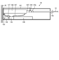
- FIG. 1 is a diagram showing an example of a mode of use of the balancer according to the first embodiment of the present invention.
- a current collector (pantograph) 21 on the roof of the train 20 is in contact with the overhead wire 10, and electric energy is supplied from the overhead wire 10.
- the overhead wire 10 includes a catenary wire 11, a trolley wire 12 that comes into contact with the pantograph 21 to supply power to the train 20, and a hanger 13.
- the trolley wire 12 is supported by a hanger 13 attached to the overhead wire 11.
- One end of the overhead wire 10 is fixed to the support column 30, and the other end is connected to the balancer 14.
- the balancer 14 is fixed to the support column 30.
- the balancer 14 adjusts the tensions of the overhead wire 11 and the trolley wire 12. For stable power supply to the train 20, it is important to stabilize the tension of the trolley wire 12. Therefore, it is required to stably control the tension of the overhead wire 10 by the balancer 14.
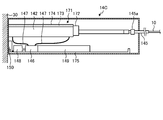
- FIG. 2 is a partial cross-sectional view showing the configuration of the balancer according to the first embodiment of the present invention.
- the balancer 14 includes a housing 141, a hydraulic cylinder 142, a piston rod 143, a tension sensor 144, a rod 145, a hydraulic pump 146, a hydraulic hose 147, a motor 148, a hydraulic oil tank 149, and drive control. It has a part 150 and the like.
- the actuator is composed of a hydraulic cylinder 142, a piston rod 143, a hydraulic pump 146, a hydraulic hose 147, and a motor 148.
- the housing 141 accommodates a hydraulic cylinder 142, a piston rod 143, a tension sensor 144, a rod 145, a hydraulic pump 146, a hydraulic hose 147, a motor 148, a hydraulic oil tank 149, and a drive control unit 150.
- the housing 141 extends a part of the rod 145 to the outside and accommodates the rod 145 so as to be able to move forward and backward in the longitudinal direction.
- the hydraulic cylinder 142 moves the piston rod 143 by the hydraulic oil supplied from the hydraulic pump 146 via the hydraulic hose 147.
- a positive pressure or a negative pressure is applied depending on the amount of hydraulic oil supplied, and the piston rod 143 moves according to the pressure.
- the tension sensor 144 is interposed between the piston rod 143 and the rod 145 and detects the tensile force of the rod 145. This tensile force corresponds to the tension of the overhead wire 10. Therefore, the tension sensor 144 detects the tension of the overhead wire 10 via the rod 145. The tension sensor 144 outputs the detected value to the drive control unit 150.
- the rod 145 is connected to the tension sensor 144, and the other end is connected to the overhead wire 10.
- the rod 145 is provided with a stopper 145a for adjusting the extension amount with respect to the housing 141.
- the stopper 145a is provided inside the housing 141, and the size of the rod 145 when viewed from the moving direction (longitudinal direction) is the opening of the hole (not shown) through which the rod 145 penetrates formed in the housing 141. Greater than size.
- the hydraulic pump 146 sends the hydraulic oil in the hydraulic oil tank 149 to the hydraulic hose 147 according to the drive of the motor 148, or sucks the hydraulic oil in the hydraulic cylinder 142 via the hydraulic hose 147.
- the motor 148 is configured by using, for example, a stepping motor, and is driven (rotated) according to a pulse signal from the control unit 154, and the amount of rotation thereof is controlled.
- the control unit 154 can grasp the position of the piston rod 143 in the hydraulic cylinder 142 by controlling the rotation amount of the motor 148.
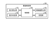
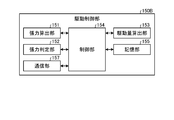
- FIG. 3 is a block diagram showing a configuration of a drive control unit in the balancer according to the first embodiment of the present invention.
- the drive control unit 150 includes a tension calculation unit 151, a tension determination unit 152, a drive amount calculation unit 153, a control unit 154, and a storage unit 155.
- the drive control unit 150 is realized by mounting a circuit on a substrate.
- the tension calculation unit 151 is communicably connected to the tension sensor 144.
- the tension calculation unit 151 calculates the tension applied to the rod 145 based on the detected value acquired from the tension sensor 144.
- the tension calculation unit 151 outputs the calculated tension to the control unit 154.
- the tension determination unit 152 determines whether or not the tension calculated by the tension calculation unit 151 is appropriate for the tension set in the overhead wire 10.
- the tension determination unit 152 determines whether or not the tension calculated by the tension calculation unit 151 satisfies the threshold value.
- An upper limit value and a lower limit value are set as the threshold value, and the range between the upper limit value and the lower limit value is an allowable range in which it is determined that the tension is appropriate.
- the tension determination unit 152 calculates the difference between the preset tension (reference tension) and the tension calculated by the tension calculation unit 151, compares this difference with the threshold value, and determines whether the tension is appropriate. It may be determined whether or not.
- the drive amount calculation unit 153 calculates the drive amount for moving the rod 145 when the tension does not satisfy the threshold value.
- the drive amount calculation unit 153 calculates the movement direction and the movement amount of the rod 145 based on the tension calculated by the tension calculation unit 151, and calculates the drive amount of the motor according to the movement direction and the movement amount.
- the drive amount is, for example, an output value.
- the drive amount calculation unit 153 increases the tension of the overhead wire 10 by pulling the piston rod 143 into the hydraulic cylinder 142.
- the drive amount calculation unit 153 reduces the tension of the overhead wire 10 by discharging the piston rod 143 from the hydraulic cylinder 142.
- the drive amount calculation unit 153 outputs the amount of movement in a predetermined direction as a positive (+) value, and outputs the amount of movement in the opposite direction as a negative ( ⁇ ) value.
- the control unit 154 controls the operation processing of each component of the balancer 14. For example, when the control unit 154 acquires the detected value from the tension sensor 144, the control unit 154 causes the tension adjustment process of the overhead wire 10 to be performed. The control unit 154 drives the motor 148 according to the drive amount calculated by the drive amount calculation unit 153.
- the control unit 154 needs to control the motor 148 at preset intervals to maintain the protrusion amount of the piston rod 143.
- the tension adjustment process may be performed before the time when the train 20 passes, without performing the tension adjustment while the train 20 does not pass.
- the "time when the train 20 passes” here refers to the time when the train 20 approaches the section of the trolley line where the tension is adjusted by the tension control of the overhead wire 10.
- the wave propagation speed which is the speed at which waves propagate on a trolley line or the like.
- the wave propagation velocity (m / s) is c
- the tension of the trolley wire is T
- the unit length mass (kg / m) of the trolley wire is ⁇
- the wave propagation velocity c is expressed by the following equation (1).
- NS. c ⁇ (T / ⁇ ) ⁇ ⁇ ⁇ (1)
- the tension may be higher than usual by acquiring the proximity information of the train in advance.
- the speed of trains is increasing year by year, but as described above, it is possible to cope with the speeding up by temporarily increasing the tension when the train approaches.
- the tension is increased by the braking amount of the actuator or the like. It is possible to increase the tension without changing the balancer.
- tension control may be performed in units of several seconds during the period before and after the train 20 passes.
- the trolley wire 12 sways due to the contact between the trolley wire 12 and the pantograph 21, and the tension of the trolley wire 12 changes due to the influence of this sway.
- By controlling the tension of the overhead wire 10 in units of several seconds it is possible to maintain an appropriate tension even when the tension changes due to the shaking of the trolley wire 12 when passing through the train 20.
- the storage unit 155 stores a program for the control unit 154 to execute various operations (for example, a program for driving a hydraulic pump), a threshold value (allowable range) related to tension determination processing, and the like.
- the storage unit 155 is configured by using a volatile memory or a non-volatile memory, or is configured by combining them.
- the storage unit 155 is configured by using a RAM (Random Access Memory), a ROM (Read Only Memory), or the like.
- the tension calculation unit 151, the tension determination unit 152, the drive amount calculation unit 153, and the control unit 154 each execute various specific functions such as a processor such as a CPU (Central Processing Unit) and an ASIC (Application Specific Integrated Circuit). It is configured using a processor such as an arithmetic circuit.
- a processor such as a CPU (Central Processing Unit) and an ASIC (Application Specific Integrated Circuit). It is configured using a processor such as an arithmetic circuit.
- the tension of the overhead wire 10 connected to the piston rod 143 is adjusted by controlling the piston rod 143 using the hydraulic pump 146.
- a hydraulic tension adjusting mechanism such as a hydraulic pump 146
- the tension change rate can be reduced without increasing the number of members (for example, coil springs), so that the size of the balancer can be suppressed.
- the rate of change in tension can be reduced.
- the tension of the overhead wire 10 can be adjusted.
- the tension of the overhead wire 10 is adjusted by a hydraulic actuator
- the overhead wire 10 is operated by an actuator different from the hydraulic type such as an actuator using a chain and an actuator using a ball screw.
- the tension of the can be adjusted.
- FIG. 4 is a block diagram showing a configuration of a drive control unit in the balancer according to the first modification of the first embodiment of the present invention.
- the balancer 14 described above includes a drive control unit 150A instead of the drive control unit 150.
- the drive control unit 150A will be described.
- the same components as those in the first embodiment described above are designated by the same reference numerals.
- the drive control unit 150A includes a tension calculation unit 151, a tension determination unit 152, a drive amount calculation unit 153, a control unit 154, a storage unit 155, and an overhead wire wear detection unit 156.
- the overhead wire wear detection unit 156 detects the wear of the overhead wire 10 by detecting the elongation of the overhead wire 10 based on the relative position of the piston rod 143 in the hydraulic cylinder 142 and the tension detected at that time. For example, when the cross-sectional area of the trolley wire 12 changes due to wear or the like, the tension generated with respect to the tension of the rod 145 changes. Therefore, the position of the piston rod 143 in the hydraulic cylinder 142 changes when the tension is the same between the wear-free trolley wire 12 and the worn trolley wire 12.
- the elongation amount Y of the trolley wire 12 is expressed by the following equation, where L is the length of the trolley wire 12, x is the tension change amount, E is the Young's modulus of the trolley wire 12, and S is the cross-sectional area of the trolley wire 12. It can be expressed as 2).
- Y L ⁇ x / (E ⁇ S) ⁇ ⁇ ⁇ (2) If the tension of the trolley wire 12 having an unworn cross-sectional area of 120 mm 2 and an overhead wire length of 800 m and a Young's modulus of 10500 kgf / mm 2 is changed by 275 kgf, the trolley wire without wear is determined from the above equation (2).
- the elongation amount of the trolley wire 12 is 173 mm, and the elongation amount of the trolley wire 12 is 232 m when the cross-sectional area of the trolley wire 12 is 3/4 (90 mm 2). In this case, even if the tension is adjusted to be the same, there is a difference of about 60 mm in the elongation of the trolley wire 12. This difference can be detected as a change in the position of the piston rod 143 in the hydraulic cylinder 142.
- the overhead wire wear detection unit 156 detects the elongation of the overhead wire 10 from the change in the position of the piston rod 143. Here, the elongation of the overhead wire 10 as a whole due to the wear of the trolley wire 12 or the like is detected.
- the position of the piston rod 143 in the hydraulic cylinder 142 can be determined based on the amount of rotation of the motor 148.
- the overhead wire wear detection unit 156 detects the elongation of the overhead wire 10 based on the difference between the position of the piston rod 143 in the hydraulic cylinder 142 and the reference position when the tension is adjusted to the reference tension.
- the reference position is, for example, the position of the piston rod 143 in the hydraulic cylinder 142 when the tension of the overhead wire 10 without wear, which is stored in advance in the storage unit 155, is set as the set tension, or the wear immediately after the overhead wire 10 is installed. This is the position of the piston rod 143 in the hydraulic cylinder 142 when the tension of the overhead wire 10 is set as the set tension.
- the set tension referred to here is, for example, a tension set to be adjusted with respect to the overhead wire 10. For example, when the calculated difference is larger than the preset threshold value, the overhead wire wear detection unit 156 determines that the overhead wire 10 is stretched and worn.
- the threshold value is set based on, for example, the relationship between the strength of the overhead wire 10 having a cross-sectional area that decreases due to wear and the strength required for the overhead wire 10.
- the overhead wire wear detection unit 156 outputs the determination result to the control unit 154.
- control unit 154 When the control unit 154 acquires the determination result from the overhead wire wear detection unit 156, the control unit 154 stores the determination result in the storage unit 155 or transmits the determination result to the center that centrally manages the plurality of balancers 14. When transmitting the determination result to the center, the control unit 154 transmits information (for example, ID, etc.) for identifying itself (balancer 14) and the overhead wire 10 to be tension-adjusted together with the determination result.
- information for example, ID, etc.
- the tension of the overhead wire 10 connected to the piston rod 143 is adjusted by controlling the piston rod 143 using the hydraulic pump 146 as in the first embodiment.
- a hydraulic tension adjusting mechanism such as a hydraulic pump 146
- the tension change rate can be reduced without increasing the number of members (for example, coil springs), so that the increase in size of the balancer is suppressed.
- the rate of change in tension can be reduced.
- the overhead wire wear detection unit 156 detects the wear of the overhead wire 10 based on the position of the piston rod 143, so that the administrator can grasp the replacement time of the overhead wire 10. Is possible. As a result, the overhead wire 10 can be replaced at an appropriate timing.
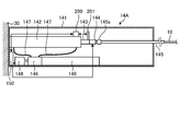
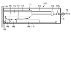
- FIG. 5 is a partial cross-sectional view showing the configuration of the balancer according to the second modification of the first embodiment of the present invention.
- the balancer 14A according to the second modification further includes a laser distance sensor 200 and a reflector 201 with respect to the balancer 14 described above.
- the configurations of the laser distance sensor 200 and the reflector 201 will be described.
- the same components as those in the first embodiment described above are designated by the same reference numerals.
- the laser distance sensor 200 is provided on the outer surface of the hydraulic cylinder 142.
- the reflector 201 is erected on the piston rod 143 at a position where the laser emitted by the laser distance sensor 200 can be reflected.
- the laser distance sensor 200 emits a laser toward the reflector 201 and receives the laser reflected by the reflector 201.
- the laser distance sensor 200 outputs, for example, information on the time from when the laser is emitted by itself to when the laser is reflected by the reflector 201 and received, or information on the phase difference between the emitted light and the return light to the control unit 154. ..
- the control unit 154 measures the distance between the laser distance sensor 200 and the reflector 201 based on the information acquired from the laser distance sensor 200.
- the control unit 154 determines the position of the piston rod 143 in the hydraulic cylinder 142 based on the measured distance, the position of the laser distance sensor 200 in the hydraulic cylinder 142, and the position of the reflector 201 in the piston rod 143.
- Other processes related to tension control are the same as those in the first embodiment.
- the tension of the overhead wire 10 connected to the piston rod 143 is adjusted by controlling the piston rod 143 using the hydraulic pump 146 as in the first embodiment.
- the tension change rate can be reduced without increasing the number of members (for example, coil springs), so that the increase in size of the balancer is suppressed.
- the rate of change in tension can be reduced.
- the position of the piston rod 143 is detected based on the laser reflected by the reflector 201, so that the detection result is based on the position of the reflector 201 according to the actual movement position of the piston rod 143. It becomes. Therefore, in the position detection using the laser distance sensor 200 and the reflector 201, the position of the piston rod 143 can be detected more accurately.
- the method of detecting the position of the piston rod 143 in the hydraulic cylinder 142 is not limited to the motor control and the distance measurement by the laser described above, and a known method can be used.
- FIGS. 6 and 7 are partial cross-sectional views showing the configuration of the balancer according to the third modification of the first embodiment of the present invention.
- the balancer 14B according to the third modification further includes a rust preventive mechanism 161 with respect to the balancer 14 described above.
- the rust preventive mechanism 161 will be described.
- the same components as those in the first embodiment described above are designated by the same reference numerals.
- the rust preventive mechanism 161 has a sealing case 162, an expansion / contraction member 163, and an oil pan 164.
- the sealed case 162 has a cylindrical shape with one end connected to the hydraulic cylinder 142, and the piston rod 143 is inserted through the sealed case 162.
- the telescopic member 163 is provided in the sealed case 162, one end of which is fixed to the inner wall of the sealed case 162, and the other end of which is fixed to the tension sensor 144.
- the telescopic member 163 forms a sealing space for sealing the end portion of the piston rod 143 on the tension sensor 144 side by the telescopic member 163 and the inner wall of the sealing case 162.
- the sealed space is filled with an inert gas. Examples of the inert gas include nitrogen and rare gas elements.
- the oil pan 164 receives the hydraulic oil leaking from the hydraulic cylinder 142 and the like.
- the telescopic member 163 expands and contracts in conjunction with the movement of the piston rod 143. For example, when the piston rod 143 is pulled into the hydraulic cylinder 142 (see FIG. 7) from the state where the tension sensor 144 is located outside the sealed case 162 (see FIG. 6), the telescopic member 163 moves the piston rod 143. It contracts in tandem. At this time, since the sealed state between the expansion / contraction member 163 and the sealing case 162 is maintained, the piston rod 143 is maintained in the sealed state in the atmosphere of the inert gas.
- the tension of the overhead wire 10 connected to the piston rod 143 is adjusted by controlling the piston rod 143 using the hydraulic pump 146 as in the first embodiment.
- a hydraulic tension adjusting mechanism such as a hydraulic pump 146
- the tension change rate can be reduced without increasing the number of members (for example, coil springs), so that the increase in size of the balancer is suppressed.
- the rate of change in tension can be reduced.
- the rust preventive mechanism 161 keeps the piston rod 143 in a sealed state in an inert gas atmosphere regardless of the movement of the piston rod 143. The generation of rust can be suppressed.
- FIGS. 8 and 9 are partial cross-sectional views showing the configuration of the balancer according to the fourth modification of the first embodiment of the present invention.
- the balancer 14C according to the fourth modification further includes a rust preventive mechanism 171 with respect to the balancer 14 described above.
- the rust preventive mechanism 171 will be described.
- the same components as those in the first embodiment described above are designated by the same reference numerals.
- the rust preventive mechanism 171 includes a wiper 172, a support member 173, a wiper hydraulic cylinder 174, and an oil pan 175.
- the wiper 172 is supplied with rust preventive oil via the wiper hydraulic cylinder 174. Therefore, the wiper 172 is in a state of containing rust preventive oil.
- the rust preventive oil may be the hydraulic oil described above, or may be an oil selected according to the material of the piston rod 143.
- the hydraulic oil tank 149 may be used in common, or a tank different from the hydraulic oil tank 149 may be provided. Further, when supplying rust preventive oil different from the hydraulic oil to the wiper 172, a tank different from the hydraulic oil tank 149 is provided.
- the support member 173 supports the wiper 172 at one end, and the other end is housed in the wiper hydraulic cylinder 174.
- the support member 173 is provided so as to be able to move forward and backward with respect to the wiper hydraulic cylinder 174 under the control of the control unit 154.
- the oil pan 175 receives the hydraulic oil leaking from the wiper 172 and the like.
- the control unit 154 reciprocates the wiper 172 between the end of the piston rod 143 on the hydraulic cylinder 142 side and the tension sensor 144 by moving the support member 173. By the reciprocating movement of the wiper 172, the surface of the piston rod 143 is coated with working or rust preventive oil.
- the control unit 154 may reciprocate the wiper 172 at preset intervals, or may reciprocate the wiper 172 according to the instruction of the administrator.
- the tension of the overhead wire 10 connected to the piston rod 143 is adjusted by controlling the piston rod 143 using the hydraulic pump 146 as in the first embodiment.
- the tension change rate can be reduced without increasing the number of members (for example, coil springs), so that the increase in size of the balancer is suppressed.
- the rate of change in tension can be reduced.
- the rust preventive mechanism 171 keeps the piston rod 143 covered with the hydraulic oil or the rust preventive oil, so that the occurrence of rust on the piston rod 143 can be suppressed. can.
- regular rust prevention treatment is effective. Since the piston rod 143 may move from the minimum movement position to the maximum movement position of the stroke over a year, for example, it is exposed to the outside air for a long period of time, and it is preferable to carry out rust prevention treatment on a regular basis.
- the rack and pinion may be driven by a motor to move the wiper 172.
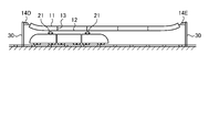
- FIG. 10 is a diagram showing an example of a mode of use of the balancer according to the second embodiment of the present invention.
- the first embodiment described above an example in which one end of the overhead wire 10 is fixed to the support column 30 and the balancer 14 is provided at the other end has been described, but in the second embodiment, balancers are provided at both ends of the overhead wire 10.
- the same components as those in the first embodiment described above are designated by the same reference numerals.
- one end of the overhead wire 10 is connected to the support column 30 via the balancer 14D, and the other end is connected to the support column 30 via the balancer 14E.
- the tension of the overhead wire 10 is adjusted by two balancers 14D and 14E.
- the balancers 14D and 14E provided on the same overhead wire 10 for tension adjustment function as a pair of balancers.
- the balancers 14D and 14E each have the same configuration as the balancer 14 described above. That is, the balancers 14D and 14E include the housing 141, the hydraulic cylinder 142, the piston rod 143, the tension sensor 144, the rod 145, the hydraulic pump 146, the hydraulic hose 147, the motor 148, and the hydraulic oil tank 149. And a drive control unit 150, respectively.
- Each control unit 154 of the balancers 14D and 14E controls the piston rod 143 based on the calculated tension.
- the control timings of the piston rods 143 of the balancer 14D and the balancer 14E may be individual or may be synchronized. When the piston rods 143 are controlled at the same time, they may be controlled at different times.
- the drive control unit 150 of each balancer may change the set tension based on the position of the piston rod 143 and the detection result by the tension sensor 144.
- the drive control unit 150 changes the set tension by performing control imitating Hooke's law in which the elongation of the spring is proportional to the load below the elastic limit.
- the stroke amount of the balancer is increased to control the tension to an appropriate level.
- the balancer does not have a spring member (for example, a coil spring)
- the stroke amount of the piston rod 143 in both balancers is controlled to the same extent even if the tension is controlled to an appropriate value, for example.
- the stroke amount of one balancer may increase.
- the balancers mutually.
- the tension between the two balancers is adjusted so as to be balanced, and the position of the piston rod 143 in the paired balancers (here, balancers 14D and 14E) in the hydraulic cylinder 142 (in this case, the balancers 14D and 14E) without communicating and controlling the information of The stroke amount) can be controlled to a relatively similar level.
- the tension of the overhead wire 10 connected to the piston rod 143 is adjusted by controlling the piston rod 143 using the hydraulic pump 146 as in the first embodiment.
- a hydraulic tension adjusting mechanism such as a hydraulic pump 146
- the tension change rate can be reduced without increasing the number of members (for example, coil springs), so that the size of the balancer can be suppressed.
- the rate of change in tension can be reduced.
- balancers are provided at both ends of the overhead wire 10 to adjust the tension at both ends of the overhead wire 10, so that the tension adjustment width (total movement amount by each piston rod 143). ) Can be taken large.
- the balancers 14A to 14C according to the first and second modifications of the first embodiment may be used.
- FIG. 11 is a block diagram showing a configuration of a drive control unit in the balancer according to the first modification of the second embodiment of the present invention.
- the balancers 14D and 14E described above include a drive control unit 150B instead of the drive control unit 150.
- the drive control unit 150B will be described.
- the same components as those in the first and second embodiments described above are designated by the same reference numerals.
- the drive control unit 150B includes a tension calculation unit 151, a tension determination unit 152, a drive amount calculation unit 153, a control unit 154, a storage unit 155, and a communication unit 157.
- the communication unit 157 transmits and receives a control signal to and from the other balancer in the pair.
- the communication unit 157 of the balancer 14D transmits and receives a control signal to and from the communication unit 157 of the paired balancer 14E.
- the communication unit 157 may transmit and receive signals using the overhead wire 10 as a transmission path, or may transmit and receive signals by wireless communication.
- the balancers 14D and 14E control the movement of the piston rod 143 in cooperation with each other.
- one is set as the main balancer and the other is set as the secondary balancer, and the balancers paired with the main balancer are collectively controlled.
- the control unit 154 of the balancer 14D causes the tension calculation unit 151 and the tension determination unit 152 of the balancer 14E to perform the tension determination process.
- the control unit 154 does not perform the tension adjusting process when it is determined that the tension is appropriate.
- the control unit 154 of the balancer 14E causes the tension calculation unit 151 and the tension determination unit 152 of the balancer 14E to perform the tension determination process, and the tension of the balancer 14E and the tension of the balancer 14E are determined.
- the determination result of the tension and the position information of the piston rod 143 are acquired.
- the drive amount calculation unit 153 of the balancer 14D sets the movement direction and the movement amount of the piston rod 143 of each balancer based on the tension of each balancer, the determination result, and the position of the piston rod 143.
- the control unit 154 of the balancer 14D controls the piston rod 143 of the balancer 14D, and transmits control information of the piston rod 143 to the balancer 14E via the communication unit 157. At this time, the movement of the piston rod 143 between the balancer 14D and the balancer 14E may be performed individually or synchronously.
- the tension of the overhead wire 10 connected to the piston rod 143 is adjusted by controlling the piston rod 143 using the hydraulic pump 146 as in the second embodiment.
- a hydraulic tension adjusting mechanism such as a hydraulic pump 146
- the tension change rate can be reduced without increasing the number of members (for example, coil springs), so that the increase in size of the balancer is suppressed.
- the rate of change in tension can be reduced.
- the balancers communicate with each other via the communication unit 157, and the piston rod 143 is controlled in an integrated manner according to the tension, so that the load applied to one balancer is reduced. be able to.
- the drive control unit of the balancer 14E includes a tension calculation unit 151, a tension determination unit 152, a control unit 154, a storage unit 155, and a communication unit 157.
- the tension determination unit 152 of the balancer 14D determines the suitability of the tension of the balancer 14E based on the tension acquired from the balancer 14E, the balancer 14E may not have the tension determination unit 152.
- the drive control unit of the balancer 14E includes a tension calculation unit 151, a control unit 154, a storage unit 155, and a communication unit 157.
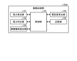
- FIG. 12 is a block diagram showing a configuration of a drive control unit in the balancer according to the second modification of the second embodiment of the present invention.
- the balancers 14D and 14E described above include a drive control unit 150C instead of the drive control unit 150.
- the drive control unit 150C will be described.
- the same components as those in the first and second embodiments described above are designated by the same reference numerals.
- the drive control unit 150C includes a tension calculation unit 151, a tension determination unit 152, a drive amount calculation unit 153, a control unit 154, a storage unit 155, an overhead wire wear detection unit 156, a communication unit 157, and a GPS (Global). It has a Positioning System) unit 158.
- at least the balancer 14D is provided with a generator that generates vibration for wear detection. An actuator may be used as the vibration generator.
- the GPS unit 158 is configured by using a receiver that receives radio waves from GPS satellites.
- the GPS unit 158 acquires time information based on the received radio wave, and outputs the acquired time information to the control unit 154.
- GNSS Global Navigation Satellite System
- the GPS unit 158 acquires time information at a preset interval or a preset time.
- the control unit 154 resets the time based on the acquired time information.
- the control unit 154 of each balancer can synchronize the time between balancers by setting the time based on GPS.
- the wear of the trolley wire 12 is detected by detecting the signal transmission speed between the balancers 14D and 14E.
- the control unit 154 of the balancer 14D when the balancer 14D is the main and the balancer 14E is the sub, the control unit 154 of the balancer 14D generates vibration for detecting the wear of the overhead wire via the overhead wire 10 (the overhead wire 11 or the trolley wire 12). It is sent to the balancer 14E to start the overhead wire wear detection process.
- the overhead wire wear detection unit 156 of the balancer 14D generates vibration for wear detection in the balancer 14E. It suffices if the balancer 14E can recognize that the vibration generated at this time is the vibration for detecting the wear of the overhead wire 10.
- the balancer 14E receives the vibration for detecting wear, it transmits a signal including the time when the vibration is received to the balancer 14D.
- the overhead wire wear detection unit 156 of the balancer 14D acquires the vibration reception time from the balancer 14E, it calculates the difference from the time when the vibration is generated by itself. This difference corresponds to the transmission time required to transmit the vibration flowing through the overhead wire 10 between the balancer 14D and the balancer 14E.
- the overhead wire wear detection unit 156 of the balancer 14D compares the calculated transmission time with the threshold value to detect the wear of the overhead wire 10.
- the threshold value here is a value corresponding to the transmission time of the overhead wire 10 (trolley wire 12) without wear, and is, for example, a preset value or a transmission time calculated immediately after the overhead wire 10 is replaced. ..
- the overhead wire wear detection unit 156 of the balancer 14D determines that the overhead wire 10 is worn when the calculated transmission time is smaller than the threshold value.
- the overhead wire wear detection unit 156 of the balancer 14D outputs the determination result to the control unit 154.
- control unit 154 When the control unit 154 acquires the judgment result from the overhead wire wear detection unit 156, the control unit 154 stores the judgment result in the storage unit 155 or transmits the judgment result to the center that centrally manages a plurality of balancers. When transmitting the determination result to the center, the control unit 154 transmits information (for example, ID, etc.) for identifying its own balancer 14D and the overhead wire 10 to be tension-adjusted together with the determination result.
- information for example, ID, etc.
- the tension of the overhead wire 10 connected to the piston rod 143 is adjusted by controlling the piston rod 143 using the hydraulic pump 146 as in the second embodiment.
- the tension change rate can be reduced without increasing the number of members (for example, coil springs), so that the increase in size of the balancer is suppressed.
- the rate of change in tension can be reduced.
- the overhead wire wear detection unit 156 detects the wear of the overhead wire 10 based on the transmission speed of the vibration between the balancers 14D and 14E. Etc. can be grasped.
- the drive control unit of the balancer 14E includes a tension calculation unit 151, a tension determination unit 152, a drive amount calculation unit 153, a control unit 154, a storage unit 155, a communication unit 157, and a GPS unit 158.
- the GPS unit 158 may not be provided.
- the signal for detecting the wear is not limited to the vibration, for example, a sound wave.
- the propagation velocity may be measured to detect the elongation of the overhead wire 10.
- one balancer is provided with a generator that generates sound, and the other balancer is provided with a receiver that receives the sound generated by the generator.
- the control device for controlling the two balancers.
- the control device may be configured to control the two balancers in an integrated manner.
- the drive control unit of each balancer has at least a control unit 154, a storage unit 155, and a communication unit 157.
- the control device acquires the detection value of the tension sensor from each balancer, determines the suitability of the tension, calculates the drive amount of the piston rod 143, and transmits the drive amount to each balancer. In this way, the control device controls each balancer by executing some of the functions of the balancers described above.
- the present invention may include various embodiments not described here, and various design changes and the like may be made within a range that does not deviate from the technical idea specified by the claims. Is possible.
- the above-described embodiment an example of adjusting the tension of the train line has been described, but in addition, the above-mentioned balancer can be adopted for the object for adjusting the tension of the wire rod.
- the balancer and the balancer system according to the present invention are suitable for reducing the tension change rate while suppressing the increase in size.
- Overhead wire 11 Overhead wire 12 Trolley wire 13 Hanger 14, 14A-14E Balancer 20 Train 21 Pantograph 30 Strut 141 Housing 142 Hydraulic cylinder 143 Piston rod 144 Tension sensor 145 Rod 146 Hydraulic pump 147 Hydraulic hose 148 Hydraulic hose 148 150A-150C Drive control unit 151 Tension calculation unit 152 Tension determination unit 153 Drive amount calculation unit 154 Control unit 155 Storage unit 156 Overhead wire wear detection unit 157 Communication unit 158 GPS unit 161 and 171 Anti-corrosion mechanism 200 Laser distance sensor 201 Reflector
Abstract
This balancer comprises: an actuator for adjusting the tension of a wire; a tension sensor disposed between the wire and the actuator for detecting the tension of the wire; and a drive control unit for controlling the actuator on the basis of the tension of the wire detected by the tension sensor.
Description
本発明は、バランサおよびバランサシステムに関するものである。
The present invention relates to a balancer and a balancer system.
従来、電車には、屋根上にある集電装置(パンタグラフ)が架線のトロリー線と接し、このトロリー線から電気エネルギーが供給される。電車への給電を安定させるためには、架線の張力が一定であることが望まれる。そのため、温度や摩耗によって変化する張力を一定になるように調整するバランサが用いられる(例えば、特許文献1を参照)。特許文献1が開示するバランサは、張力を調整する方向に伸縮するコイルばねを複数設けることによって、架線の張力を調整する。
Conventionally, a current collector (pantograph) on the roof of a train is in contact with an overhead trolley wire, and electrical energy is supplied from this trolley wire. In order to stabilize the power supply to the train, it is desirable that the tension of the overhead wire is constant. Therefore, a balancer that adjusts the tension that changes with temperature and wear to be constant is used (see, for example, Patent Document 1). The balancer disclosed in Patent Document 1 adjusts the tension of the overhead wire by providing a plurality of coil springs that expand and contract in the direction of adjusting the tension.
ところで、電車の高速化に伴って、バランサに要求される性能も高度化する。具体的には、電車の高速化に対応させるため、架線の張力変化率を小さくすることが求められる。しかしながら、特許文献1が開示するバランサは、張力変化率を小さくしようとすると、コイルばねを長くするか、コイルばねの数を増やすことになり、バランサ自体が大型化してしまう。
By the way, as the speed of trains increases, so does the performance required of balancers. Specifically, it is required to reduce the tension change rate of the overhead wire in order to correspond to the speeding up of the train. However, in the balancer disclosed in Patent Document 1, if the tension change rate is to be reduced, the coil springs are lengthened or the number of coil springs is increased, and the balancer itself becomes large.
本発明は、上記に鑑みてなされたものであって、大型化を抑制しつつ、張力変化率を低減することができるバランサおよびバランサシステムを提供することを目的とする。
The present invention has been made in view of the above, and an object of the present invention is to provide a balancer and a balancer system capable of reducing the rate of change in tension while suppressing the increase in size.
上述した課題を解決し、目的を達成するために、本発明に係るバランサは、線材の張力を調整するアクチュエータと、前記線材および前記アクチュエータの間に設けられ、前記線材の張力を検出する張力センサと、前記張力センサが検出した前記線材の張力に基づいて、前記アクチュエータを制御する駆動制御部と、を備えることを特徴とする。
In order to solve the above-mentioned problems and achieve the object, the balancer according to the present invention is provided between the actuator for adjusting the tension of the wire and the wire and the actuator, and is a tension sensor for detecting the tension of the wire. A drive control unit that controls the actuator based on the tension of the wire rod detected by the tension sensor.
また、本発明に係るバランサは、上記の発明において、前記アクチュエータは、油圧シリンダと、前記油圧シリンダに作動油を供給する油圧ポンプと、前記油圧シリンダに対して進退自在に設けられ、前記油圧シリンダに供給される前記作動油によって移動するピストンロッドと、を有することを特徴とする。
Further, in the balancer according to the present invention, in the above invention, the actuator is provided with a hydraulic cylinder, a hydraulic pump for supplying hydraulic oil to the hydraulic cylinder, and the hydraulic cylinder so as to be movable back and forth with respect to the hydraulic cylinder. It is characterized by having a piston rod that is moved by the hydraulic oil supplied to the vehicle.
また、本発明に係るバランサは、上記の発明において、前記駆動制御部は、設定された張力に調整した後の前記ピストンロッドの位置をもとに、前記線材の伸びを検出することを特徴とする。
Further, the balancer according to the present invention is characterized in that, in the above invention, the drive control unit detects the elongation of the wire rod based on the position of the piston rod after adjusting to the set tension. do.
また、本発明に係るバランサは、上記の発明において、前記駆動制御部は、前記線材を経由して、組をなす他のバランサに伝送した信号の伝送時間をもとに、前記線材の摩耗を検出することを特徴とする。
Further, in the above invention, the balancer according to the present invention causes the drive control unit to wear the wire rod based on the transmission time of the signal transmitted to the other balancer in the set via the wire rod. It is characterized by detecting.
また、本発明に係るバランサは、上記の発明において、前記駆動制御部は、組をなす他のバランサの張力に関する情報を取得し、当該駆動制御部を有する自バランサと、前記他のバランサとにおける各アクチュエータの駆動量を算出することを特徴とする。
Further, in the balancer according to the present invention, in the above invention, the drive control unit acquires information on the tension of another balancer forming a set, and the self-balancer having the drive control unit and the other balancer. It is characterized in that the driving amount of each actuator is calculated.
また、本発明に係るバランサは、上記の発明において、前記ピストンロッドを防錆する防錆機構をさらに備えることを特徴とする。
Further, the balancer according to the present invention is characterized in that, in the above invention, the balancer further includes a rust preventive mechanism for preventing the piston rod from rusting.
また、本発明に係るバランサは、上記の発明において、前記防錆機構は、前記ピストンロッドを不活性ガス雰囲気下で密封することを特徴とする。
Further, the balancer according to the present invention is characterized in that, in the above invention, the rust preventive mechanism seals the piston rod in an inert gas atmosphere.
また、本発明に係るバランサは、上記の発明において、前記防錆機構は、前記ピストンロッドに防錆油を塗布することを特徴とする。
Further, the balancer according to the present invention is characterized in that, in the above invention, the rust preventive mechanism applies rust preventive oil to the piston rod.
また、本発明に係るバランサは、上記の発明において、前記線材は、電車のパンタグラフと接触するトロリー線を含み、前記駆動制御部は、前記電車が制御対象の前記トロリー線を通過する時刻よりも所定の時間だけ前の時刻に、前記張力センサに前記線材の張力を検出させ、検出した張力に基づいて前記アクチュエータを制御する、ことを特徴とする。
Further, in the balancer according to the present invention, in the above invention, the wire rod includes a trolley wire in contact with the pantograph of the train, and the drive control unit is more than the time when the train passes the trolley wire to be controlled. It is characterized in that the tension sensor detects the tension of the wire rod at a time before a predetermined time, and the actuator is controlled based on the detected tension.
また、本発明に係るバランサシステムは、線材の一端に接続し、該線材の張力を調整する第1のバランサと、前記第1のバランサと同一の線材の他端に接続し、該線材の張力を調整する第2のバランサと、を備え、前記第1のバランサは、前記線材の張力を調整する第1のアクチュエータと、前記線材および前記第1のアクチュエータの間に設けられ、前記線材の張力を検出する第1の張力センサと、前記第1の張力センサが検出した前記線材の張力に基づいて、前記第1のアクチュエータを制御する第1の駆動制御部と、前記第2のバランサと通信する第1の通信部と、を有し、前記第1のバランサは、前記線材の張力を調整する第2のアクチュエータと、前記線材および前記第2のアクチュエータの間に設けられ、前記線材の張力を検出する第2の張力センサと、前記第2の張力センサが検出した前記線材の張力に基づいて、前記第2のアクチュエータを制御する第2の駆動制御部と、前記第1のバランサと通信する第2の通信部と、を有することを特徴とする。
Further, the balancer system according to the present invention is connected to one end of a wire rod to adjust the tension of the wire rod, and is connected to the other end of the same wire rod as the first balancer to adjust the tension of the wire rod. A second balancer for adjusting the tension of the wire rod is provided, and the first balancer is provided between the first actuator for adjusting the tension of the wire rod and the wire rod and the first actuator, and the tension of the wire rod is provided. The first tension sensor that detects the above, the first drive control unit that controls the first actuator based on the tension of the wire rod detected by the first tension sensor, and the second balancer communicate with each other. The first balancer is provided between the second actuator for adjusting the tension of the wire rod, the wire rod and the second actuator, and has the tension of the wire rod. The second tension sensor that detects the above, the second drive control unit that controls the second actuator based on the tension of the wire rod detected by the second tension sensor, and the first balancer communicate with each other. It is characterized by having a second communication unit and a second communication unit.
また、本発明に係るバランサシステムは、上記の発明において、前記第1の駆動制御部は、前記線材を経由して前記第2のバランサに伝送した信号の伝送時間をもとに、前記線材の摩耗を検出することを特徴とする。
Further, in the balancer system according to the present invention, in the above invention, the first drive control unit of the wire rod is based on the transmission time of a signal transmitted to the second balancer via the wire rod. It is characterized by detecting wear.
また、本発明に係るバランサシステムは、上記の発明において、前記第1の駆動制御部は、前記第2のバランサの張力に関する情報を取得し、当該第1のバランサと前記第2のバランサとにおける各アクチュエータの駆動量を算出することを特徴とする。
Further, in the balancer system according to the present invention, in the above invention, the first drive control unit acquires information regarding the tension of the second balancer, and the first balancer and the second balancer are used. It is characterized in that the driving amount of each actuator is calculated.
また、本発明に係るバランサシステムは、上記の発明において、前記第1のアクチュエータは、第1の油圧シリンダと、前記第1の油圧シリンダに第1の作動油を供給する第1の油圧ポンプと、前記第1の油圧シリンダに対して進退自在に設けられ、前記第1の油圧シリンダに供給される前記第1の作動油によって移動する第1のピストンロッドと、を有し、前記第2のアクチュエータは、第2の油圧シリンダと、前記第2の油圧シリンダに第2の作動油を供給する第2の油圧ポンプと、前記第2の油圧シリンダに対して進退自在に設けられ、前記第2の油圧シリンダに供給される前記第2の作動油によって移動する第2のピストンロッドと、を有することを特徴とする。
Further, in the balancer system according to the present invention, in the above invention, the first actuator includes a first hydraulic cylinder and a first hydraulic pump that supplies a first hydraulic oil to the first hydraulic cylinder. The second piston rod is provided so as to be movable back and forth with respect to the first hydraulic cylinder and is moved by the first hydraulic oil supplied to the first hydraulic cylinder. The actuator is provided so as to be movable back and forth with respect to the second hydraulic cylinder, the second hydraulic pump that supplies the second hydraulic oil to the second hydraulic cylinder, and the second hydraulic cylinder. It is characterized by having a second piston rod that is moved by the second hydraulic oil supplied to the hydraulic cylinder of the above.
また、本発明に係るバランサシステムは、上記の発明において、前記第1の駆動制御部は、前記第1のアクチュエータの制御情報と、前記第1の張力センサによる検出結果とに基づいて、設定張力を変更し、前記第2の駆動制御部は、前記第2のアクチュエータの制御情報と、前記第2の張力センサによる検出結果とに基づいて、設定張力を変更する、ことを特徴とする。
Further, in the balancer system according to the present invention, in the above invention, the first drive control unit sets a tension based on the control information of the first actuator and the detection result by the first tension sensor. The second drive control unit changes the set tension based on the control information of the second actuator and the detection result by the second tension sensor.
本発明によれば、大型化を抑制しつつ、張力変化率を低減することができるという効果を奏する。
According to the present invention, it is possible to reduce the rate of change in tension while suppressing the increase in size.
以下、本発明を実施するための形態を図面と共に詳細に説明する。なお、以下の実施の形態により本発明が限定されるものではない。また、以下の説明において参照する各図は、本発明の内容を理解し得る程度に形状、大きさ、および位置関係を概略的に示してあるに過ぎない。すなわち、本発明は各図で例示された形状、大きさ、および位置関係のみに限定されるものではない。
Hereinafter, a mode for carrying out the present invention will be described in detail together with drawings. The present invention is not limited to the following embodiments. In addition, each of the figures referred to in the following description merely schematically shows the shape, size, and positional relationship to the extent that the content of the present invention can be understood. That is, the present invention is not limited to the shape, size, and positional relationship exemplified in each figure.
(実施の形態1)
図1は、本発明の実施の形態1に係るバランサの使用態様の一例を示す図である。電車20には、当該電車20の屋根上にある集電装置(パンタグラフ)21が架線10と接し、この架線10から電気エネルギーが供給される。架線10は、ちょう架線11と、パンタグラフ21と接触して電車20に給電するトロリー線12と、ハンガー13とを有する。トロリー線12は、ちょう架線11に取り付けられるハンガー13に支持される。架線10は、一端が支柱30に固定され、他端がバランサ14に接続される。バランサ14は、支柱30に固定される。架線10においては、バランサ14によって、ちょう架線11およびトロリー線12の張力が調整される。電車20への安定した電力供給は、トロリー線12の張力を安定させることが重要である。このため、バランサ14による架線10の張力制御を安定して行うことが求められる。 (Embodiment 1)
FIG. 1 is a diagram showing an example of a mode of use of the balancer according to the first embodiment of the present invention. A current collector (pantograph) 21 on the roof of thetrain 20 is in contact with the overhead wire 10, and electric energy is supplied from the overhead wire 10. The overhead wire 10 includes a catenary wire 11, a trolley wire 12 that comes into contact with the pantograph 21 to supply power to the train 20, and a hanger 13. The trolley wire 12 is supported by a hanger 13 attached to the overhead wire 11. One end of the overhead wire 10 is fixed to the support column 30, and the other end is connected to the balancer 14. The balancer 14 is fixed to the support column 30. In the overhead wire 10, the balancer 14 adjusts the tensions of the overhead wire 11 and the trolley wire 12. For stable power supply to the train 20, it is important to stabilize the tension of the trolley wire 12. Therefore, it is required to stably control the tension of the overhead wire 10 by the balancer 14.
図1は、本発明の実施の形態1に係るバランサの使用態様の一例を示す図である。電車20には、当該電車20の屋根上にある集電装置(パンタグラフ)21が架線10と接し、この架線10から電気エネルギーが供給される。架線10は、ちょう架線11と、パンタグラフ21と接触して電車20に給電するトロリー線12と、ハンガー13とを有する。トロリー線12は、ちょう架線11に取り付けられるハンガー13に支持される。架線10は、一端が支柱30に固定され、他端がバランサ14に接続される。バランサ14は、支柱30に固定される。架線10においては、バランサ14によって、ちょう架線11およびトロリー線12の張力が調整される。電車20への安定した電力供給は、トロリー線12の張力を安定させることが重要である。このため、バランサ14による架線10の張力制御を安定して行うことが求められる。 (Embodiment 1)
FIG. 1 is a diagram showing an example of a mode of use of the balancer according to the first embodiment of the present invention. A current collector (pantograph) 21 on the roof of the
図2は、本発明の実施の形態1に係るバランサの構成を示す部分断面図である。バランサ14は、筐体141と、油圧シリンダ142と、ピストンロッド143と、張力センサ144と、ロッド145と、油圧ポンプ146と、油圧ホース147と、モータ148と、作動油タンク149と、駆動制御部150とを有する。本実施の形態1では、油圧シリンダ142、ピストンロッド143、油圧ポンプ146、油圧ホース147およびモータ148によってアクチュエータを構成する。
FIG. 2 is a partial cross-sectional view showing the configuration of the balancer according to the first embodiment of the present invention. The balancer 14 includes a housing 141, a hydraulic cylinder 142, a piston rod 143, a tension sensor 144, a rod 145, a hydraulic pump 146, a hydraulic hose 147, a motor 148, a hydraulic oil tank 149, and drive control. It has a part 150 and the like. In the first embodiment, the actuator is composed of a hydraulic cylinder 142, a piston rod 143, a hydraulic pump 146, a hydraulic hose 147, and a motor 148.
筐体141は、油圧シリンダ142、ピストンロッド143、張力センサ144、ロッド145、油圧ポンプ146、油圧ホース147、モータ148、作動油タンク149および駆動制御部150を収容する。筐体141は、ロッド145の一部を外部に延出するとともに、ロッド145の長手方向に進退自在に収容している。
The housing 141 accommodates a hydraulic cylinder 142, a piston rod 143, a tension sensor 144, a rod 145, a hydraulic pump 146, a hydraulic hose 147, a motor 148, a hydraulic oil tank 149, and a drive control unit 150. The housing 141 extends a part of the rod 145 to the outside and accommodates the rod 145 so as to be able to move forward and backward in the longitudinal direction.
油圧シリンダ142は、油圧ポンプ146から油圧ホース147を介して供給される作動油によって、ピストンロッド143を移動させる。油圧シリンダ142では、作動油の供給量に応じて陽圧または陰圧となり、その圧力に応じてピストンロッド143が移動する。
The hydraulic cylinder 142 moves the piston rod 143 by the hydraulic oil supplied from the hydraulic pump 146 via the hydraulic hose 147. In the hydraulic cylinder 142, a positive pressure or a negative pressure is applied depending on the amount of hydraulic oil supplied, and the piston rod 143 moves according to the pressure.
張力センサ144は、ピストンロッド143とロッド145との間に介在し、ロッド145の引張力を検出する。この引張力は、架線10の張力に相当する。このため、張力センサ144は、ロッド145を介して架線10の張力を検出する。張力センサ144は、検出値を駆動制御部150に出力する。
The tension sensor 144 is interposed between the piston rod 143 and the rod 145 and detects the tensile force of the rod 145. This tensile force corresponds to the tension of the overhead wire 10. Therefore, the tension sensor 144 detects the tension of the overhead wire 10 via the rod 145. The tension sensor 144 outputs the detected value to the drive control unit 150.
ロッド145は、一端が張力センサ144に接続し、他端が架線10に接続する。ロッド145には、筐体141に対する延出量を調整するストッパー145aが設けられる。ストッパー145aは、筐体141の内部に設けられ、ロッド145の移動方向(長手方向)からみた大きさが、筐体141に形成される、ロッド145が貫通する孔部(図示略)の開口の大きさよりも大きい。
One end of the rod 145 is connected to the tension sensor 144, and the other end is connected to the overhead wire 10. The rod 145 is provided with a stopper 145a for adjusting the extension amount with respect to the housing 141. The stopper 145a is provided inside the housing 141, and the size of the rod 145 when viewed from the moving direction (longitudinal direction) is the opening of the hole (not shown) through which the rod 145 penetrates formed in the housing 141. Greater than size.
油圧ポンプ146は、モータ148の駆動にしたがって作動油タンク149内の作動油を油圧ホース147に送り込むか、または、油圧ホース147を介して油圧シリンダ142内の作動油を吸引する。
モータ148は、例えばステッピングモータを用いて構成され、制御部154からのパルス信号にしたがって駆動(回転)し、その回転量が制御される。制御部154は、モータ148の回転量を制御することによって、油圧シリンダ142におけるピストンロッド143の位置を把握することができる。 Thehydraulic pump 146 sends the hydraulic oil in the hydraulic oil tank 149 to the hydraulic hose 147 according to the drive of the motor 148, or sucks the hydraulic oil in the hydraulic cylinder 142 via the hydraulic hose 147.
Themotor 148 is configured by using, for example, a stepping motor, and is driven (rotated) according to a pulse signal from the control unit 154, and the amount of rotation thereof is controlled. The control unit 154 can grasp the position of the piston rod 143 in the hydraulic cylinder 142 by controlling the rotation amount of the motor 148.
モータ148は、例えばステッピングモータを用いて構成され、制御部154からのパルス信号にしたがって駆動(回転)し、その回転量が制御される。制御部154は、モータ148の回転量を制御することによって、油圧シリンダ142におけるピストンロッド143の位置を把握することができる。 The
The
続いて、駆動制御部150の構成について、図3を参照して説明する。図3は、本発明の実施の形態1に係るバランサにおける駆動制御部の構成を示すブロック図である。駆動制御部150は、張力算出部151と、張力判定部152と、駆動量算出部153と、制御部154と、記憶部155とを有する。駆動制御部150は、基板に回路を実装させることによって実現される。
Subsequently, the configuration of the drive control unit 150 will be described with reference to FIG. FIG. 3 is a block diagram showing a configuration of a drive control unit in the balancer according to the first embodiment of the present invention. The drive control unit 150 includes a tension calculation unit 151, a tension determination unit 152, a drive amount calculation unit 153, a control unit 154, and a storage unit 155. The drive control unit 150 is realized by mounting a circuit on a substrate.
張力算出部151は、張力センサ144と通信可能に接続される。張力算出部151は、張力センサ144から取得した検出値に基づいて、ロッド145に加わる張力を算出する。張力算出部151は、算出した張力を、制御部154に出力する。
The tension calculation unit 151 is communicably connected to the tension sensor 144. The tension calculation unit 151 calculates the tension applied to the rod 145 based on the detected value acquired from the tension sensor 144. The tension calculation unit 151 outputs the calculated tension to the control unit 154.
張力判定部152は、張力算出部151によって算出された張力が、架線10に設定される張力に対して適切か否かを判定する。張力判定部152は、張力算出部151が算出した張力が、閾値を満たすか否かを判定する。なお、閾値としては、上限値と下限値とが設定され、この上限値と下限値との間が、適切な張力であると判定される許容範囲となる。なお、張力判定部152は、予め設定されている張力(基準張力)と、張力算出部151が算出した張力との差を算出し、この差を閾値と比較して、適切な張力であるか否かを判定するようにしてもよい。
The tension determination unit 152 determines whether or not the tension calculated by the tension calculation unit 151 is appropriate for the tension set in the overhead wire 10. The tension determination unit 152 determines whether or not the tension calculated by the tension calculation unit 151 satisfies the threshold value. An upper limit value and a lower limit value are set as the threshold value, and the range between the upper limit value and the lower limit value is an allowable range in which it is determined that the tension is appropriate. The tension determination unit 152 calculates the difference between the preset tension (reference tension) and the tension calculated by the tension calculation unit 151, compares this difference with the threshold value, and determines whether the tension is appropriate. It may be determined whether or not.
駆動量算出部153は、張力が閾値を満たさなかった場合に、ロッド145を移動させるための駆動量を算出する。駆動量算出部153は、張力算出部151が算出した張力に基づいてロッド145の移動方向および移動量を算出し、この移動方向および移動量に応じたモータの駆動量を算出する。駆動量は、例えば出力値である。
駆動量算出部153は、算出された張力が許容範囲よりも小さい場合、ピストンロッド143を油圧シリンダ142内に引き込むことによって架線10の張力を大きくする。これに対し、駆動量算出部153は、算出された張力が許容範囲よりも大きい場合、ピストンロッド143を油圧シリンダ142から排出することによって架線10の張力を小さくする。駆動量算出部153は、例えば、所定の方向への移動量をプラス(+)の値で出力し、その反対方向への移動量をマイナス(-)の値で出力する。 The driveamount calculation unit 153 calculates the drive amount for moving the rod 145 when the tension does not satisfy the threshold value. The drive amount calculation unit 153 calculates the movement direction and the movement amount of the rod 145 based on the tension calculated by the tension calculation unit 151, and calculates the drive amount of the motor according to the movement direction and the movement amount. The drive amount is, for example, an output value.
When the calculated tension is smaller than the permissible range, the driveamount calculation unit 153 increases the tension of the overhead wire 10 by pulling the piston rod 143 into the hydraulic cylinder 142. On the other hand, when the calculated tension is larger than the allowable range, the drive amount calculation unit 153 reduces the tension of the overhead wire 10 by discharging the piston rod 143 from the hydraulic cylinder 142. For example, the drive amount calculation unit 153 outputs the amount of movement in a predetermined direction as a positive (+) value, and outputs the amount of movement in the opposite direction as a negative (−) value.
駆動量算出部153は、算出された張力が許容範囲よりも小さい場合、ピストンロッド143を油圧シリンダ142内に引き込むことによって架線10の張力を大きくする。これに対し、駆動量算出部153は、算出された張力が許容範囲よりも大きい場合、ピストンロッド143を油圧シリンダ142から排出することによって架線10の張力を小さくする。駆動量算出部153は、例えば、所定の方向への移動量をプラス(+)の値で出力し、その反対方向への移動量をマイナス(-)の値で出力する。 The drive
When the calculated tension is smaller than the permissible range, the drive
制御部154は、バランサ14の各構成部品の動作処理を制御する。制御部154は、例えば、張力センサ144から検出値を取得した際に、架線10の張力調整処理を実施させる。制御部154は、駆動量算出部153が算出した駆動量にしたがって、モータ148を駆動させる。
The control unit 154 controls the operation processing of each component of the balancer 14. For example, when the control unit 154 acquires the detected value from the tension sensor 144, the control unit 154 causes the tension adjustment process of the overhead wire 10 to be performed. The control unit 154 drives the motor 148 according to the drive amount calculated by the drive amount calculation unit 153.
ここで、油圧式では、油圧ポンプ146によってピストンロッド143の位置を維持させても、ピストンロッド143の油圧シリンダ142からの突出量が経時的に変化する。このため、制御部154は、予め設定された間隔でモータ148を制御して、ピストンロッド143の突出量を維持する必要がある。この際、電車20が通過しない間は張力調整を実施せずに、電車20が通過する時刻よりも所定時間前に張力調整処理を実施するようにしてもよい。ここでいう「電車20が通過する時刻」とは、架線10の張力制御によって張力が調整されるトロリー線の区間に、電車20が差し掛かる時刻をさす。
電車の高速走行時の集電性能を高めるためには、トロリー線等において波が伝わる速度である「波動伝搬速度」を高める必要がある。波動伝搬速度(m/s)をc、トロリー線の張力をT、トロリー線の単位長質量(kg/m)をρとすると、波動伝搬速度cは、下式(1)のように表される。
c=√(T/ρ) ・・・(1)
上式(1)より、波動伝搬速度を高めるためには、トロリー線の高張力化等が必要であることが分かる。例えば、事前に電車の近接情報等を取得する等して、通常よりも張力を高めておく等の制御を行ってもよい。また、電車の高速化が年々進んでいるが、上述したように、電車が近付いてきた際に一時的に張力を高めることによって、高速化に対応することが可能である。
従来のばね式バランサでは、高張力化に対応するためには、ばねを大型化する等の必要があるが、本実施の形態の方式を採用するバランサでは、アクチュエータの制動量等によって高張力化が可能であり、バランサを変更せずに、高張力化が可能になる。 Here, in the hydraulic type, even if the position of thepiston rod 143 is maintained by the hydraulic pump 146, the amount of protrusion of the piston rod 143 from the hydraulic cylinder 142 changes with time. Therefore, the control unit 154 needs to control the motor 148 at preset intervals to maintain the protrusion amount of the piston rod 143. At this time, the tension adjustment process may be performed before the time when the train 20 passes, without performing the tension adjustment while the train 20 does not pass. The "time when the train 20 passes" here refers to the time when the train 20 approaches the section of the trolley line where the tension is adjusted by the tension control of the overhead wire 10.
In order to improve the current collecting performance of a train at high speed, it is necessary to increase the "wave propagation speed", which is the speed at which waves propagate on a trolley line or the like. Assuming that the wave propagation velocity (m / s) is c, the tension of the trolley wire is T, and the unit length mass (kg / m) of the trolley wire is ρ, the wave propagation velocity c is expressed by the following equation (1). NS.
c = √ (T / ρ) ・ ・ ・ (1)
From the above equation (1), it can be seen that it is necessary to increase the tension of the trolley wire in order to increase the wave propagation velocity. For example, the tension may be higher than usual by acquiring the proximity information of the train in advance. In addition, the speed of trains is increasing year by year, but as described above, it is possible to cope with the speeding up by temporarily increasing the tension when the train approaches.
In the conventional spring type balancer, it is necessary to increase the size of the spring in order to cope with the increase in tension, but in the balancer adopting the method of the present embodiment, the tension is increased by the braking amount of the actuator or the like. It is possible to increase the tension without changing the balancer.
電車の高速走行時の集電性能を高めるためには、トロリー線等において波が伝わる速度である「波動伝搬速度」を高める必要がある。波動伝搬速度(m/s)をc、トロリー線の張力をT、トロリー線の単位長質量(kg/m)をρとすると、波動伝搬速度cは、下式(1)のように表される。
c=√(T/ρ) ・・・(1)
上式(1)より、波動伝搬速度を高めるためには、トロリー線の高張力化等が必要であることが分かる。例えば、事前に電車の近接情報等を取得する等して、通常よりも張力を高めておく等の制御を行ってもよい。また、電車の高速化が年々進んでいるが、上述したように、電車が近付いてきた際に一時的に張力を高めることによって、高速化に対応することが可能である。
従来のばね式バランサでは、高張力化に対応するためには、ばねを大型化する等の必要があるが、本実施の形態の方式を採用するバランサでは、アクチュエータの制動量等によって高張力化が可能であり、バランサを変更せずに、高張力化が可能になる。 Here, in the hydraulic type, even if the position of the
In order to improve the current collecting performance of a train at high speed, it is necessary to increase the "wave propagation speed", which is the speed at which waves propagate on a trolley line or the like. Assuming that the wave propagation velocity (m / s) is c, the tension of the trolley wire is T, and the unit length mass (kg / m) of the trolley wire is ρ, the wave propagation velocity c is expressed by the following equation (1). NS.
c = √ (T / ρ) ・ ・ ・ (1)
From the above equation (1), it can be seen that it is necessary to increase the tension of the trolley wire in order to increase the wave propagation velocity. For example, the tension may be higher than usual by acquiring the proximity information of the train in advance. In addition, the speed of trains is increasing year by year, but as described above, it is possible to cope with the speeding up by temporarily increasing the tension when the train approaches.
In the conventional spring type balancer, it is necessary to increase the size of the spring in order to cope with the increase in tension, but in the balancer adopting the method of the present embodiment, the tension is increased by the braking amount of the actuator or the like. It is possible to increase the tension without changing the balancer.
また、電車20が通過する前後の期間では、数秒単位で張力制御を実施してもよい。電車20が通過すると、トロリー線12とパンタグラフ21との接触によってトロリー線12が揺れ、この揺れの影響によってトロリー線12の張力が変化する。数秒単位で架線10の張力制御を実施することによって、電車20通過時のトロリー線12の揺れに起因する張力変化が生じた場合でも適切な張力を維持することができる。
Further, tension control may be performed in units of several seconds during the period before and after the train 20 passes. When the train 20 passes, the trolley wire 12 sways due to the contact between the trolley wire 12 and the pantograph 21, and the tension of the trolley wire 12 changes due to the influence of this sway. By controlling the tension of the overhead wire 10 in units of several seconds, it is possible to maintain an appropriate tension even when the tension changes due to the shaking of the trolley wire 12 when passing through the train 20.
記憶部155は、制御部154が各種動作を実行するためのプログラム(例えば油圧ポンプを駆動するためのプログラム)や、張力の判定処理に関する閾値(許容範囲)等を記憶する。記憶部155は、揮発性メモリや不揮発性メモリを用いて構成されるか、またはそれらを組み合わせて構成される。例えば、記憶部155は、RAM(Random Access Memory)、ROM(Read Only Memory)等を用いて構成される。
The storage unit 155 stores a program for the control unit 154 to execute various operations (for example, a program for driving a hydraulic pump), a threshold value (allowable range) related to tension determination processing, and the like. The storage unit 155 is configured by using a volatile memory or a non-volatile memory, or is configured by combining them. For example, the storage unit 155 is configured by using a RAM (Random Access Memory), a ROM (Read Only Memory), or the like.
張力算出部151、張力判定部152、駆動量算出部153および制御部154は、それぞれ、CPU(Central Processing Unit)等のプロセッサや、ASIC(Application Specific Integrated Circuit)等の特定の機能を実行する各種演算回路等のプロセッサを用いて構成される。
The tension calculation unit 151, the tension determination unit 152, the drive amount calculation unit 153, and the control unit 154 each execute various specific functions such as a processor such as a CPU (Central Processing Unit) and an ASIC (Application Specific Integrated Circuit). It is configured using a processor such as an arithmetic circuit.
上述した実施の形態1では、油圧ポンプ146を用いてピストンロッド143を制御することによって、ピストンロッド143に接続する架線10の張力を調整するようにした。実施の形態1によれば、油圧ポンプ146等の油圧による張力調整機構を用いることによって、部材(例えばコイルばね)を増やさずに張力変化率を小さくすることができるため、バランサの大型化を抑制しつつ、張力変化率を低減することができる。
In the first embodiment described above, the tension of the overhead wire 10 connected to the piston rod 143 is adjusted by controlling the piston rod 143 using the hydraulic pump 146. According to the first embodiment, by using a hydraulic tension adjusting mechanism such as a hydraulic pump 146, the tension change rate can be reduced without increasing the number of members (for example, coil springs), so that the size of the balancer can be suppressed. At the same time, the rate of change in tension can be reduced.
また、ちょう架線11やトロリー線12は、材料が変更されると、温度に対する伸縮性が変化する場合がある。この際、材料によっては、変更前の材料よりも温度による伸縮量が大きくなることがあるが、実施の形態1に係るバランサは、この変化に対し、大型化や重量化することを抑制しつつ、架線10の張力調整を実施することができる。
Further, when the material of the overhead wire 11 and the trolley wire 12 is changed, the elasticity with respect to temperature may change. At this time, depending on the material, the amount of expansion and contraction due to temperature may be larger than that of the material before the change, but the balancer according to the first embodiment suppresses the increase in size and weight in response to this change. , The tension of the overhead wire 10 can be adjusted.
なお、実施の形態1では、油圧式のアクチュエータによって架線10の張力を調整する例について説明したが、チェーンを用いたアクチュエータや、ボールねじを用いたアクチュエータ等、油圧式とは異なるアクチュエータによって架線10の張力を調整することができる。
In the first embodiment, an example in which the tension of the overhead wire 10 is adjusted by a hydraulic actuator has been described, but the overhead wire 10 is operated by an actuator different from the hydraulic type such as an actuator using a chain and an actuator using a ball screw. The tension of the can be adjusted.
(実施の形態1の変形例1)
次に、上述した実施の形態1の変形例1について、図4を参照して説明する。図4は、本発明の実施の形態1の変形例1に係るバランサにおける駆動制御部の構成を示すブロック図である。変形例1は、上述したバランサ14において、駆動制御部150に代えて駆動制御部150Aを備える。以下、駆動制御部150Aについて説明する。なお、上述した実施の形態1と同じ構成には、同じ符号を付す。 (Modification 1 of Embodiment 1)
Next, a modification 1 of the first embodiment described above will be described with reference to FIG. FIG. 4 is a block diagram showing a configuration of a drive control unit in the balancer according to the first modification of the first embodiment of the present invention. In the first modification, thebalancer 14 described above includes a drive control unit 150A instead of the drive control unit 150. Hereinafter, the drive control unit 150A will be described. The same components as those in the first embodiment described above are designated by the same reference numerals.
次に、上述した実施の形態1の変形例1について、図4を参照して説明する。図4は、本発明の実施の形態1の変形例1に係るバランサにおける駆動制御部の構成を示すブロック図である。変形例1は、上述したバランサ14において、駆動制御部150に代えて駆動制御部150Aを備える。以下、駆動制御部150Aについて説明する。なお、上述した実施の形態1と同じ構成には、同じ符号を付す。 (Modification 1 of Embodiment 1)
Next, a modification 1 of the first embodiment described above will be described with reference to FIG. FIG. 4 is a block diagram showing a configuration of a drive control unit in the balancer according to the first modification of the first embodiment of the present invention. In the first modification, the
駆動制御部150Aは、張力算出部151と、張力判定部152と、駆動量算出部153と、制御部154と、記憶部155と、架線摩耗検出部156とを有する。
The drive control unit 150A includes a tension calculation unit 151, a tension determination unit 152, a drive amount calculation unit 153, a control unit 154, a storage unit 155, and an overhead wire wear detection unit 156.
架線摩耗検出部156は、油圧シリンダ142におけるピストンロッド143の相対的な位置と、その際に検出される張力とに基づいて架線10の伸びを検出することによって、架線10の摩耗を検出する。例えば、トロリー線12は、摩耗等によって断面積が変化すると、ロッド145の引張りに対して発生する張力が変化する。このため、摩耗のないトロリー線12と、摩耗したトロリー線12とでは、同じ張力とする場合に、油圧シリンダ142におけるピストンロッド143の位置が変わる。例えば、トロリー線12の伸び量Yは、トロリー線12の長さをL、張力変化量をx、トロリー線12の縦弾性係数をE、トロリー線12の断面積をSとすると、下式(2)のように表すことができる。
Y=L×x/(E×S) ・・・(2)
仮に、未摩耗の断面積が120mm2、架線長が800m、縦弾性係数が10500kgf/mm2のトロリー線12の張力を275kgfだけ変化させた場合、上式(2)より、摩耗のないトロリー線12の伸び量は173mmとなり、トロリー線12の断面積が3/4(90mm2)となった場合のトロリー線12の伸び量は232mとなる。この場合、同じ張力に調整したとしても、トロリー線12の伸びとして約60mmの差が生じる。この差は、油圧シリンダ142におけるピストンロッド143の位置の変化として検出することができる。 The overhead wirewear detection unit 156 detects the wear of the overhead wire 10 by detecting the elongation of the overhead wire 10 based on the relative position of the piston rod 143 in the hydraulic cylinder 142 and the tension detected at that time. For example, when the cross-sectional area of the trolley wire 12 changes due to wear or the like, the tension generated with respect to the tension of the rod 145 changes. Therefore, the position of the piston rod 143 in the hydraulic cylinder 142 changes when the tension is the same between the wear-free trolley wire 12 and the worn trolley wire 12. For example, the elongation amount Y of the trolley wire 12 is expressed by the following equation, where L is the length of the trolley wire 12, x is the tension change amount, E is the Young's modulus of the trolley wire 12, and S is the cross-sectional area of the trolley wire 12. It can be expressed as 2).
Y = L × x / (E × S) ・ ・ ・ (2)
If the tension of thetrolley wire 12 having an unworn cross-sectional area of 120 mm 2 and an overhead wire length of 800 m and a Young's modulus of 10500 kgf / mm 2 is changed by 275 kgf, the trolley wire without wear is determined from the above equation (2). The elongation amount of the trolley wire 12 is 173 mm, and the elongation amount of the trolley wire 12 is 232 m when the cross-sectional area of the trolley wire 12 is 3/4 (90 mm 2). In this case, even if the tension is adjusted to be the same, there is a difference of about 60 mm in the elongation of the trolley wire 12. This difference can be detected as a change in the position of the piston rod 143 in the hydraulic cylinder 142.
Y=L×x/(E×S) ・・・(2)
仮に、未摩耗の断面積が120mm2、架線長が800m、縦弾性係数が10500kgf/mm2のトロリー線12の張力を275kgfだけ変化させた場合、上式(2)より、摩耗のないトロリー線12の伸び量は173mmとなり、トロリー線12の断面積が3/4(90mm2)となった場合のトロリー線12の伸び量は232mとなる。この場合、同じ張力に調整したとしても、トロリー線12の伸びとして約60mmの差が生じる。この差は、油圧シリンダ142におけるピストンロッド143の位置の変化として検出することができる。 The overhead wire
Y = L × x / (E × S) ・ ・ ・ (2)
If the tension of the
架線摩耗検出部156は、ピストンロッド143の位置の変化から、架線10の伸びを検出する。ここでは、トロリー線12の摩耗等による架線10全体としての伸びが検出される。油圧シリンダ142におけるピストンロッド143の位置は、モータ148の回転量に基づいて求めることができる。架線摩耗検出部156は、基準張力に調整した際の油圧シリンダ142におけるピストンロッド143の位置と、基準位置との差に基づいて、架線10の伸びを検出する。基準位置は、例えば記憶部155に予め記憶される、摩耗がない架線10の張力を設定張力とした際の、油圧シリンダ142におけるピストンロッド143の位置、または、架線10を設置した直後の、摩耗のない架線10の張力を設定張力とした際の、油圧シリンダ142におけるピストンロッド143の位置である。ここでいう設定張力は、例えば、架線10に対して調整するように設定されている張力である。
架線摩耗検出部156は、例えば、算出した差が、予め設定されている閾値よりも大きい場合、架線10に伸びが生じ、摩耗していると判断する。閾値は、例えば、摩耗によって減少する断面積の架線10の強度と、架線10に求められる強度との関係に基づいて設定される。架線摩耗検出部156は、判断結果を制御部154に出力する。 The overhead wirewear detection unit 156 detects the elongation of the overhead wire 10 from the change in the position of the piston rod 143. Here, the elongation of the overhead wire 10 as a whole due to the wear of the trolley wire 12 or the like is detected. The position of the piston rod 143 in the hydraulic cylinder 142 can be determined based on the amount of rotation of the motor 148. The overhead wire wear detection unit 156 detects the elongation of the overhead wire 10 based on the difference between the position of the piston rod 143 in the hydraulic cylinder 142 and the reference position when the tension is adjusted to the reference tension. The reference position is, for example, the position of the piston rod 143 in the hydraulic cylinder 142 when the tension of the overhead wire 10 without wear, which is stored in advance in the storage unit 155, is set as the set tension, or the wear immediately after the overhead wire 10 is installed. This is the position of the piston rod 143 in the hydraulic cylinder 142 when the tension of the overhead wire 10 is set as the set tension. The set tension referred to here is, for example, a tension set to be adjusted with respect to the overhead wire 10.
For example, when the calculated difference is larger than the preset threshold value, the overhead wirewear detection unit 156 determines that the overhead wire 10 is stretched and worn. The threshold value is set based on, for example, the relationship between the strength of the overhead wire 10 having a cross-sectional area that decreases due to wear and the strength required for the overhead wire 10. The overhead wire wear detection unit 156 outputs the determination result to the control unit 154.
架線摩耗検出部156は、例えば、算出した差が、予め設定されている閾値よりも大きい場合、架線10に伸びが生じ、摩耗していると判断する。閾値は、例えば、摩耗によって減少する断面積の架線10の強度と、架線10に求められる強度との関係に基づいて設定される。架線摩耗検出部156は、判断結果を制御部154に出力する。 The overhead wire
For example, when the calculated difference is larger than the preset threshold value, the overhead wire
制御部154は、架線摩耗検出部156から判断結果を取得すると、該判断結果を記憶部155に記憶させたり、複数のバランサ14を集中管理するセンターに判断結果を送信したりする。センターに判断結果を送信する際、制御部154は、自身(バランサ14)や、張力調整対象の架線10を特定するための情報(例えば、ID等)を判断結果とともに送信する。
When the control unit 154 acquires the determination result from the overhead wire wear detection unit 156, the control unit 154 stores the determination result in the storage unit 155 or transmits the determination result to the center that centrally manages the plurality of balancers 14. When transmitting the determination result to the center, the control unit 154 transmits information (for example, ID, etc.) for identifying itself (balancer 14) and the overhead wire 10 to be tension-adjusted together with the determination result.
上述した変形例1では、実施の形態1と同様に、油圧ポンプ146を用いてピストンロッド143を制御することによって、ピストンロッド143に接続する架線10の張力を調整するようにした。変形例1によれば、油圧ポンプ146等の油圧による張力調整機構を用いることによって、部材(例えばコイルばね)を増やさずに張力変化率を小さくすることができるため、バランサの大型化を抑制しつつ、張力変化率を低減することができる。
In the above-described modification 1, the tension of the overhead wire 10 connected to the piston rod 143 is adjusted by controlling the piston rod 143 using the hydraulic pump 146 as in the first embodiment. According to the first modification, by using a hydraulic tension adjusting mechanism such as a hydraulic pump 146, the tension change rate can be reduced without increasing the number of members (for example, coil springs), so that the increase in size of the balancer is suppressed. At the same time, the rate of change in tension can be reduced.
さらに、変形例1によれば、架線摩耗検出部156が、ピストンロッド143の位置に基づいて架線10の摩耗を検出するようにしたので、管理者に、架線10の交換時期等を把握させることが可能となる。これにより、架線10を適切なタイミングで交換することができる。
Further, according to the first modification, the overhead wire wear detection unit 156 detects the wear of the overhead wire 10 based on the position of the piston rod 143, so that the administrator can grasp the replacement time of the overhead wire 10. Is possible. As a result, the overhead wire 10 can be replaced at an appropriate timing.
(実施の形態1の変形例2)
次に、上述した実施の形態1の変形例2について、図5を参照して説明する。図5は、本発明の実施の形態1の変形例2に係るバランサの構成を示す部分断面図である。変形例2に係るバランサ14Aは、上述したバランサ14に対し、レーザー距離センサ200および反射板201をさらに備える。以下、レーザー距離センサ200および反射板201の構成について説明する。なお、上述した実施の形態1と同じ構成には、同じ符号を付す。 (Modification 2 of Embodiment 1)
Next, a modification 2 of the first embodiment described above will be described with reference to FIG. FIG. 5 is a partial cross-sectional view showing the configuration of the balancer according to the second modification of the first embodiment of the present invention. Thebalancer 14A according to the second modification further includes a laser distance sensor 200 and a reflector 201 with respect to the balancer 14 described above. Hereinafter, the configurations of the laser distance sensor 200 and the reflector 201 will be described. The same components as those in the first embodiment described above are designated by the same reference numerals.
次に、上述した実施の形態1の変形例2について、図5を参照して説明する。図5は、本発明の実施の形態1の変形例2に係るバランサの構成を示す部分断面図である。変形例2に係るバランサ14Aは、上述したバランサ14に対し、レーザー距離センサ200および反射板201をさらに備える。以下、レーザー距離センサ200および反射板201の構成について説明する。なお、上述した実施の形態1と同じ構成には、同じ符号を付す。 (Modification 2 of Embodiment 1)
Next, a modification 2 of the first embodiment described above will be described with reference to FIG. FIG. 5 is a partial cross-sectional view showing the configuration of the balancer according to the second modification of the first embodiment of the present invention. The
レーザー距離センサ200は、油圧シリンダ142の外表面に設けられる。
反射板201は、ピストンロッド143において、レーザー距離センサ200が出射するレーザーを反射可能な位置に立設される。 Thelaser distance sensor 200 is provided on the outer surface of the hydraulic cylinder 142.
Thereflector 201 is erected on the piston rod 143 at a position where the laser emitted by the laser distance sensor 200 can be reflected.
反射板201は、ピストンロッド143において、レーザー距離センサ200が出射するレーザーを反射可能な位置に立設される。 The
The
レーザー距離センサ200は、反射板201に向けてレーザーを出射し、反射板201が反射したレーザーを受光する。レーザー距離センサ200は、例えば自身がレーザーを出射してから反射板201で反射して受光するまでの時間に関する情報、または、出射光と戻り光との位相差に関する情報を制御部154に出力する。
The laser distance sensor 200 emits a laser toward the reflector 201 and receives the laser reflected by the reflector 201. The laser distance sensor 200 outputs, for example, information on the time from when the laser is emitted by itself to when the laser is reflected by the reflector 201 and received, or information on the phase difference between the emitted light and the return light to the control unit 154. ..
制御部154は、レーザー距離センサ200から取得した情報に基づいて、レーザー距離センサ200と反射板201との間の距離を測定する。制御部154は、測定した距離と、油圧シリンダ142におけるレーザー距離センサ200の位置と、ピストンロッド143における反射板201の位置とをもとに、油圧シリンダ142におけるピストンロッド143の位置を決定する。
このほかの張力制御に係る処理は、実施の形態1と同様である。 Thecontrol unit 154 measures the distance between the laser distance sensor 200 and the reflector 201 based on the information acquired from the laser distance sensor 200. The control unit 154 determines the position of the piston rod 143 in the hydraulic cylinder 142 based on the measured distance, the position of the laser distance sensor 200 in the hydraulic cylinder 142, and the position of the reflector 201 in the piston rod 143.
Other processes related to tension control are the same as those in the first embodiment.
このほかの張力制御に係る処理は、実施の形態1と同様である。 The
Other processes related to tension control are the same as those in the first embodiment.
上述した変形例2では、実施の形態1と同様に、油圧ポンプ146を用いてピストンロッド143を制御することによって、ピストンロッド143に接続する架線10の張力を調整するようにした。変形例2によれば、油圧ポンプ146等の油圧による張力調整機構を用いることによって、部材(例えばコイルばね)を増やさずに張力変化率を小さくすることができるため、バランサの大型化を抑制しつつ、張力変化率を低減することができる。
In the above-described modification 2, the tension of the overhead wire 10 connected to the piston rod 143 is adjusted by controlling the piston rod 143 using the hydraulic pump 146 as in the first embodiment. According to the second modification, by using a hydraulic tension adjusting mechanism such as a hydraulic pump 146, the tension change rate can be reduced without increasing the number of members (for example, coil springs), so that the increase in size of the balancer is suppressed. At the same time, the rate of change in tension can be reduced.
また、変形例2では、反射板201が反射したレーザーに基づいてピストンロッド143の位置が検出されるため、検出結果が、実際にピストンロッド143の移動位置に応じた反射板201の位置によるものとなる。このため、レーザー距離センサ200および反射板201を用いた位置検出では、一層正確にピストンロッド143の位置を検出することができる。
Further, in the second modification, the position of the piston rod 143 is detected based on the laser reflected by the reflector 201, so that the detection result is based on the position of the reflector 201 according to the actual movement position of the piston rod 143. It becomes. Therefore, in the position detection using the laser distance sensor 200 and the reflector 201, the position of the piston rod 143 can be detected more accurately.
なお、油圧シリンダ142におけるピストンロッド143の位置の検出方法については、上述したモータ制御およびレーザーによる距離測定に限らず、公知の手法を用いることができる。
The method of detecting the position of the piston rod 143 in the hydraulic cylinder 142 is not limited to the motor control and the distance measurement by the laser described above, and a known method can be used.
(実施の形態1の変形例3)
次に、上述した実施の形態1の変形例3について、図6および図7を参照して説明する。図6および図7は、本発明の実施の形態1の変形例3に係るバランサの構成を示す部分断面図である。変形例3に係るバランサ14Bは、上述したバランサ14に対し、防錆機構161をさらに備える。以下、防錆機構161について説明する。なお、上述した実施の形態1と同じ構成には、同じ符号を付す。 (Modification 3 of Embodiment 1)
Next, a modification 3 of the first embodiment described above will be described with reference to FIGS. 6 and 7. 6 and 7 are partial cross-sectional views showing the configuration of the balancer according to the third modification of the first embodiment of the present invention. Thebalancer 14B according to the third modification further includes a rust preventive mechanism 161 with respect to the balancer 14 described above. Hereinafter, the rust preventive mechanism 161 will be described. The same components as those in the first embodiment described above are designated by the same reference numerals.
次に、上述した実施の形態1の変形例3について、図6および図7を参照して説明する。図6および図7は、本発明の実施の形態1の変形例3に係るバランサの構成を示す部分断面図である。変形例3に係るバランサ14Bは、上述したバランサ14に対し、防錆機構161をさらに備える。以下、防錆機構161について説明する。なお、上述した実施の形態1と同じ構成には、同じ符号を付す。 (Modification 3 of Embodiment 1)
Next, a modification 3 of the first embodiment described above will be described with reference to FIGS. 6 and 7. 6 and 7 are partial cross-sectional views showing the configuration of the balancer according to the third modification of the first embodiment of the present invention. The
防錆機構161は、密封ケース162と、伸縮部材163と、オイルパン164とを有する。
The rust preventive mechanism 161 has a sealing case 162, an expansion / contraction member 163, and an oil pan 164.
密封ケース162は、一端が油圧シリンダ142に連なる筒状をなし、ピストンロッド143を挿通する。
The sealed case 162 has a cylindrical shape with one end connected to the hydraulic cylinder 142, and the piston rod 143 is inserted through the sealed case 162.
伸縮部材163は、密封ケース162内に設けられ、一端が密封ケース162の内壁に固着され、他端が張力センサ144に固着される。伸縮部材163は、当該伸縮部材163と密封ケース162の内壁とによって、ピストンロッド143の張力センサ144側の端部を密封する密封空間を形成する。この密封空間には、不活性ガスが充填される。不活性ガスとしては、窒素や、希ガス類元素が挙げられる。
オイルパン164は、油圧シリンダ142等から漏れ落ちる作動油を受け留める。 Thetelescopic member 163 is provided in the sealed case 162, one end of which is fixed to the inner wall of the sealed case 162, and the other end of which is fixed to the tension sensor 144. The telescopic member 163 forms a sealing space for sealing the end portion of the piston rod 143 on the tension sensor 144 side by the telescopic member 163 and the inner wall of the sealing case 162. The sealed space is filled with an inert gas. Examples of the inert gas include nitrogen and rare gas elements.
Theoil pan 164 receives the hydraulic oil leaking from the hydraulic cylinder 142 and the like.
オイルパン164は、油圧シリンダ142等から漏れ落ちる作動油を受け留める。 The
The
伸縮部材163は、ピストンロッド143の移動に連動して伸縮する。例えば、張力センサ144が密封ケース162の外部に位置する状態(図6参照)から、ピストンロッド143が油圧シリンダ142に引き込まれた場合(図7参照)、伸縮部材163はピストンロッド143の移動に連動して収縮する。この際、伸縮部材163と密封ケース162との間の密封状態は維持されているため、ピストンロッド143は、不活性ガス雰囲気下での密封状態が維持される。
The telescopic member 163 expands and contracts in conjunction with the movement of the piston rod 143. For example, when the piston rod 143 is pulled into the hydraulic cylinder 142 (see FIG. 7) from the state where the tension sensor 144 is located outside the sealed case 162 (see FIG. 6), the telescopic member 163 moves the piston rod 143. It contracts in tandem. At this time, since the sealed state between the expansion / contraction member 163 and the sealing case 162 is maintained, the piston rod 143 is maintained in the sealed state in the atmosphere of the inert gas.
上述した変形例3では、実施の形態1と同様に、油圧ポンプ146を用いてピストンロッド143を制御することによって、ピストンロッド143に接続する架線10の張力を調整するようにした。変形例3によれば、油圧ポンプ146等の油圧による張力調整機構を用いることによって、部材(例えばコイルばね)を増やさずに張力変化率を小さくすることができるため、バランサの大型化を抑制しつつ、張力変化率を低減することができる。
In the above-described modification 3, the tension of the overhead wire 10 connected to the piston rod 143 is adjusted by controlling the piston rod 143 using the hydraulic pump 146 as in the first embodiment. According to the third modification, by using a hydraulic tension adjusting mechanism such as a hydraulic pump 146, the tension change rate can be reduced without increasing the number of members (for example, coil springs), so that the increase in size of the balancer is suppressed. At the same time, the rate of change in tension can be reduced.
さらに、変形例3によれば、防錆機構161によって、ピストンロッド143を、該ピストンロッド143の移動によらず不活性ガス雰囲気下での密封状態を維持するようにしたので、ピストンロッド143の錆の発生を抑制することができる。
Further, according to the modification 3, the rust preventive mechanism 161 keeps the piston rod 143 in a sealed state in an inert gas atmosphere regardless of the movement of the piston rod 143. The generation of rust can be suppressed.
(実施の形態1の変形例4)
次に、上述した実施の形態1の変形例4について、図8および図9を参照して説明する。図8および図9は、本発明の実施の形態1の変形例4に係るバランサの構成を示す部分断面図である。変形例4に係るバランサ14Cは、上述したバランサ14に対し、防錆機構171をさらに備える。以下、防錆機構171について説明する。なお、上述した実施の形態1と同じ構成には、同じ符号を付す。 (Modification 4 of Embodiment 1)
Next, a modification 4 of the first embodiment described above will be described with reference to FIGS. 8 and 9. 8 and 9 are partial cross-sectional views showing the configuration of the balancer according to the fourth modification of the first embodiment of the present invention. Thebalancer 14C according to the fourth modification further includes a rust preventive mechanism 171 with respect to the balancer 14 described above. Hereinafter, the rust preventive mechanism 171 will be described. The same components as those in the first embodiment described above are designated by the same reference numerals.
次に、上述した実施の形態1の変形例4について、図8および図9を参照して説明する。図8および図9は、本発明の実施の形態1の変形例4に係るバランサの構成を示す部分断面図である。変形例4に係るバランサ14Cは、上述したバランサ14に対し、防錆機構171をさらに備える。以下、防錆機構171について説明する。なお、上述した実施の形態1と同じ構成には、同じ符号を付す。 (Modification 4 of Embodiment 1)
Next, a modification 4 of the first embodiment described above will be described with reference to FIGS. 8 and 9. 8 and 9 are partial cross-sectional views showing the configuration of the balancer according to the fourth modification of the first embodiment of the present invention. The
防錆機構171は、ワイパー172と、支持部材173と、ワイパー用油圧シリンダ174と、オイルパン175とを有する。
The rust preventive mechanism 171 includes a wiper 172, a support member 173, a wiper hydraulic cylinder 174, and an oil pan 175.
ワイパー172は、ワイパー用油圧シリンダ174を経由して、防錆油が供給される。このため、ワイパー172は、防錆油を含んだ状態となっている。防錆油は、上述した作動油であってもよいし、ピストンロッド143の材質に応じて選択される油であってもよい。なお、ワイパー172に作動油を供給する場合は作動油タンク149を共通に用いてもよいし、作動油タンク149とは別のタンクを設けてもよい。また、ワイパー172に作動油とは異なる防錆用の油を供給する場合は作動油タンク149とは別のタンクが設けられる。
The wiper 172 is supplied with rust preventive oil via the wiper hydraulic cylinder 174. Therefore, the wiper 172 is in a state of containing rust preventive oil. The rust preventive oil may be the hydraulic oil described above, or may be an oil selected according to the material of the piston rod 143. When supplying the hydraulic oil to the wiper 172, the hydraulic oil tank 149 may be used in common, or a tank different from the hydraulic oil tank 149 may be provided. Further, when supplying rust preventive oil different from the hydraulic oil to the wiper 172, a tank different from the hydraulic oil tank 149 is provided.
支持部材173は、一端でワイパー172を支持するとともに、他端側がワイパー用油圧シリンダ174に収容される。支持部材173は、制御部154の制御のもと、ワイパー用油圧シリンダ174に対して進退自在に設けられる。
オイルパン175は、ワイパー172等から漏れ落ちる作動油を受け留める。 Thesupport member 173 supports the wiper 172 at one end, and the other end is housed in the wiper hydraulic cylinder 174. The support member 173 is provided so as to be able to move forward and backward with respect to the wiper hydraulic cylinder 174 under the control of the control unit 154.
Theoil pan 175 receives the hydraulic oil leaking from the wiper 172 and the like.
オイルパン175は、ワイパー172等から漏れ落ちる作動油を受け留める。 The
The
制御部154は、支持部材173を移動させることよって、ワイパー172を、ピストンロッド143の油圧シリンダ142側の端部と、張力センサ144との間を往復動させる。ワイパー172の往復動によって、ピストンロッド143の表面に作動用または防錆油が塗布される。制御部154は、予め設定された間隔でワイパー172を往復動させてもよいし、管理者の指示によってワイパー172を往復動させてもよい。
The control unit 154 reciprocates the wiper 172 between the end of the piston rod 143 on the hydraulic cylinder 142 side and the tension sensor 144 by moving the support member 173. By the reciprocating movement of the wiper 172, the surface of the piston rod 143 is coated with working or rust preventive oil. The control unit 154 may reciprocate the wiper 172 at preset intervals, or may reciprocate the wiper 172 according to the instruction of the administrator.
上述した変形例4では、実施の形態1と同様に、油圧ポンプ146を用いてピストンロッド143を制御することによって、ピストンロッド143に接続する架線10の張力を調整するようにした。変形例4によれば、油圧ポンプ146等の油圧による張力調整機構を用いることによって、部材(例えばコイルばね)を増やさずに張力変化率を小さくすることができるため、バランサの大型化を抑制しつつ、張力変化率を低減することができる。
In the above-described modified example 4, the tension of the overhead wire 10 connected to the piston rod 143 is adjusted by controlling the piston rod 143 using the hydraulic pump 146 as in the first embodiment. According to the fourth modification, by using a hydraulic tension adjusting mechanism such as a hydraulic pump 146, the tension change rate can be reduced without increasing the number of members (for example, coil springs), so that the increase in size of the balancer is suppressed. At the same time, the rate of change in tension can be reduced.
さらに、変形例4によれば、防錆機構171によって、ピストンロッド143が作動油または防錆油に覆われた状態を維持するようにしたので、ピストンロッド143の錆の発生を抑制することができる。特に、バランサは屋外で使用され、外気に晒されるため、定期的な防錆処理が有効である。ピストンロッド143は、例えば1年かけてストロークの最小移動位置から最大移動位置までを移動することがあるため、外気に晒される期間も長く、定期的に防錆処理を実施することが好ましい。
Further, according to the modified example 4, the rust preventive mechanism 171 keeps the piston rod 143 covered with the hydraulic oil or the rust preventive oil, so that the occurrence of rust on the piston rod 143 can be suppressed. can. In particular, since the balancer is used outdoors and exposed to the outside air, regular rust prevention treatment is effective. Since the piston rod 143 may move from the minimum movement position to the maximum movement position of the stroke over a year, for example, it is exposed to the outside air for a long period of time, and it is preferable to carry out rust prevention treatment on a regular basis.
なお、変形例4では、油圧式でワイパー172を移動させる例について説明したが、ラックアンドピニオンをモータによって駆動してワイパー172を移動させる構成としてもよい。
In the modified example 4, the example of moving the wiper 172 hydraulically has been described, but the rack and pinion may be driven by a motor to move the wiper 172.
(実施の形態2)
次に、上述した実施の形態2について、図10を参照して説明する。図10は、本発明の実施の形態2に係るバランサの使用態様の一例を示す図である。上述した実施の形態1では、架線10の一端が支柱30に固定され、他端にバランサ14が設けられる例について説明したが、実施の形態2では、架線10の両端にバランサを設ける。なお、上述した実施の形態1と同じ構成には、同じ符号を付す。 (Embodiment 2)
Next, the above-described second embodiment will be described with reference to FIG. FIG. 10 is a diagram showing an example of a mode of use of the balancer according to the second embodiment of the present invention. In the first embodiment described above, an example in which one end of theoverhead wire 10 is fixed to the support column 30 and the balancer 14 is provided at the other end has been described, but in the second embodiment, balancers are provided at both ends of the overhead wire 10. The same components as those in the first embodiment described above are designated by the same reference numerals.
次に、上述した実施の形態2について、図10を参照して説明する。図10は、本発明の実施の形態2に係るバランサの使用態様の一例を示す図である。上述した実施の形態1では、架線10の一端が支柱30に固定され、他端にバランサ14が設けられる例について説明したが、実施の形態2では、架線10の両端にバランサを設ける。なお、上述した実施の形態1と同じ構成には、同じ符号を付す。 (Embodiment 2)
Next, the above-described second embodiment will be described with reference to FIG. FIG. 10 is a diagram showing an example of a mode of use of the balancer according to the second embodiment of the present invention. In the first embodiment described above, an example in which one end of the
実施の形態2において、架線10は、一端がバランサ14Dを介して支柱30に接続され、他端がバランサ14Eを介して支柱30に接続される。架線10は、二つのバランサ14D、14Eによって張力が調整される。張力調整対象が同一の架線10に設けられるバランサ14D、14E、対をなす一組のバランサとして機能する。
In the second embodiment, one end of the overhead wire 10 is connected to the support column 30 via the balancer 14D, and the other end is connected to the support column 30 via the balancer 14E. The tension of the overhead wire 10 is adjusted by two balancers 14D and 14E. The balancers 14D and 14E provided on the same overhead wire 10 for tension adjustment function as a pair of balancers.
バランサ14D、14Eは、それぞれ、上述したバランサ14と同じ構成を有する。すなわち、バランサ14D、14Eは、筐体141と、油圧シリンダ142と、ピストンロッド143と、張力センサ144と、ロッド145と、油圧ポンプ146と、油圧ホース147と、モータ148と、作動油タンク149と、駆動制御部150とをそれぞれ有する。
The balancers 14D and 14E each have the same configuration as the balancer 14 described above. That is, the balancers 14D and 14E include the housing 141, the hydraulic cylinder 142, the piston rod 143, the tension sensor 144, the rod 145, the hydraulic pump 146, the hydraulic hose 147, the motor 148, and the hydraulic oil tank 149. And a drive control unit 150, respectively.
バランサ14D、14Eの各制御部154は、算出した張力に基づいて、ピストンロッド143を制御する。この際、バランサ14Dとバランサ14Eとのピストンロッド143の制御タイミングは、個別であってもよいし、同期をとって実施してもよい。同期をとって実施する場合、同時にピストンロッド143の制御を実施してもよいし、互いに異なる時刻に実施してもよい。
Each control unit 154 of the balancers 14D and 14E controls the piston rod 143 based on the calculated tension. At this time, the control timings of the piston rods 143 of the balancer 14D and the balancer 14E may be individual or may be synchronized. When the piston rods 143 are controlled at the same time, they may be controlled at different times.
また、各バランサの駆動制御部150は、ピストンロッド143の位置と、張力センサ144による検出結果とに基づいて、設定張力を変更してもよい。例えば、駆動制御部150は、ばねの伸びと、弾性限界以下の荷重とが比例するフックの法則を模した制御を実施して設定張力を変更する。ばね式のバランサでは、トロリー線が短くなると、その分バランサを引っ張る力が大きくなり、バランサのストローク量を大きくして適切な張力に制御する。本実施の形態2では、バランサがばね部材(例えばコイルばね)を有しないため、例えば張力が適切な値に制御されていたとしても、双方のバランサにおけるピストンロッド143のストローク量を同程度に制御しなければ、一方のバランサのストローク量だけ大きくなる場合がある。上述したように、フックの法則を模した制御を行うこと、すなわち、トロリー線12の伸縮態様の変化に伴う、張力の変化を適切なストローク量に換算する制御を行うことによって、バランサ間で互いの情報を通信して制御せずとも、二つのバランサ間の張力が釣り合うように調整されるとともに、対をなすバランサ(ここではバランサ14D、14E)におけるピストンロッド143の、油圧シリンダ142における位置(ストローク量)を相対的に同等程度に制御することができる。このように、不測の事態によってバランサ間の通信ができなくなったり、そもそもバランサ間で通信ができない仕様であったりした場合でも、ストローク量を同等程度に制御することが可能である。なお、上述した油圧式では、アクチュエータの制御情報としてピストンロッドの位置を用いる例について説明したが、チェーンを用いたアクチュエータや、ボールねじを用いたアクチュエータ等、油圧式以外の構成の場合は、例えば、モータの回転位置を制御情報として用いることができる。
Further, the drive control unit 150 of each balancer may change the set tension based on the position of the piston rod 143 and the detection result by the tension sensor 144. For example, the drive control unit 150 changes the set tension by performing control imitating Hooke's law in which the elongation of the spring is proportional to the load below the elastic limit. In a spring-type balancer, as the trolley wire becomes shorter, the force that pulls the balancer increases by that amount, and the stroke amount of the balancer is increased to control the tension to an appropriate level. In the second embodiment, since the balancer does not have a spring member (for example, a coil spring), the stroke amount of the piston rod 143 in both balancers is controlled to the same extent even if the tension is controlled to an appropriate value, for example. Otherwise, the stroke amount of one balancer may increase. As described above, by performing control that imitates Hooke's law, that is, by performing control that converts the change in tension with the change in the expansion / contraction mode of the trolley wire 12 into an appropriate stroke amount, the balancers mutually. The tension between the two balancers is adjusted so as to be balanced, and the position of the piston rod 143 in the paired balancers (here, balancers 14D and 14E) in the hydraulic cylinder 142 (in this case, the balancers 14D and 14E) without communicating and controlling the information of The stroke amount) can be controlled to a relatively similar level. In this way, even if communication between balancers becomes impossible due to an unforeseen situation, or even if the specifications are such that communication between balancers is not possible in the first place, it is possible to control the stroke amount to the same extent. In the above-mentioned hydraulic type, an example in which the position of the piston rod is used as the control information of the actuator has been described, but in the case of a configuration other than the hydraulic type, such as an actuator using a chain or an actuator using a ball screw, for example. , The rotation position of the motor can be used as control information.
上述した実施の形態2では、実施の形態1と同様に、油圧ポンプ146を用いてピストンロッド143を制御することによって、ピストンロッド143に接続する架線10の張力を調整するようにした。実施の形態2によれば、油圧ポンプ146等の油圧による張力調整機構を用いることによって、部材(例えばコイルばね)を増やさずに張力変化率を小さくすることができるため、バランサの大型化を抑制しつつ、張力変化率を低減することができる。
In the second embodiment described above, the tension of the overhead wire 10 connected to the piston rod 143 is adjusted by controlling the piston rod 143 using the hydraulic pump 146 as in the first embodiment. According to the second embodiment, by using a hydraulic tension adjusting mechanism such as a hydraulic pump 146, the tension change rate can be reduced without increasing the number of members (for example, coil springs), so that the size of the balancer can be suppressed. At the same time, the rate of change in tension can be reduced.
さらに、実施の形態2によれば、架線10の両端にバランサ(バランサ14D、14E)を設けて架線10の両端において張力が調整されるため、張力の調整幅(各ピストンロッド143による総移動量)を大きくとることができる。
Further, according to the second embodiment, balancers (balancers 14D and 14E) are provided at both ends of the overhead wire 10 to adjust the tension at both ends of the overhead wire 10, so that the tension adjustment width (total movement amount by each piston rod 143). ) Can be taken large.
なお、実施の形態2において、実施の形態1の変形例1、2に係るバランサ14A~14Cを用いてもよい。
In the second embodiment, the balancers 14A to 14C according to the first and second modifications of the first embodiment may be used.
(実施の形態2の変形例1)
次に、上述した実施の形態2の変形例1について、図11を参照して説明する。図11は、本発明の実施の形態2の変形例1に係るバランサにおける駆動制御部の構成を示すブロック図である。変形例1は、上述したバランサ14D、14Eにおいて、駆動制御部150に代えて駆動制御部150Bを備える。以下、駆動制御部150Bについて説明する。なお、上述した実施の形態1、2と同じ構成には、同じ符号を付す。 (Modification 1 of Embodiment 2)
Next, a modification 1 of the second embodiment described above will be described with reference to FIG. FIG. 11 is a block diagram showing a configuration of a drive control unit in the balancer according to the first modification of the second embodiment of the present invention. In the first modification, the balancers 14D and 14E described above include a drive control unit 150B instead of the drive control unit 150. Hereinafter, the drive control unit 150B will be described. The same components as those in the first and second embodiments described above are designated by the same reference numerals.
次に、上述した実施の形態2の変形例1について、図11を参照して説明する。図11は、本発明の実施の形態2の変形例1に係るバランサにおける駆動制御部の構成を示すブロック図である。変形例1は、上述したバランサ14D、14Eにおいて、駆動制御部150に代えて駆動制御部150Bを備える。以下、駆動制御部150Bについて説明する。なお、上述した実施の形態1、2と同じ構成には、同じ符号を付す。 (Modification 1 of Embodiment 2)
Next, a modification 1 of the second embodiment described above will be described with reference to FIG. FIG. 11 is a block diagram showing a configuration of a drive control unit in the balancer according to the first modification of the second embodiment of the present invention. In the first modification, the
駆動制御部150Bは、張力算出部151と、張力判定部152と、駆動量算出部153と、制御部154と、記憶部155と、通信部157とを有する。
The drive control unit 150B includes a tension calculation unit 151, a tension determination unit 152, a drive amount calculation unit 153, a control unit 154, a storage unit 155, and a communication unit 157.
通信部157は、対をなす他方のバランサとの間で制御信号を送受信する。例えば、バランサ14Dの通信部157は、対をなすバランサ14Eの通信部157との間で制御信号を送受信する。通信部157は、架線10を伝送経路として信号を送受信してもよいし、無線通信によって信号を送受信してもよい。
The communication unit 157 transmits and receives a control signal to and from the other balancer in the pair. For example, the communication unit 157 of the balancer 14D transmits and receives a control signal to and from the communication unit 157 of the paired balancer 14E. The communication unit 157 may transmit and receive signals using the overhead wire 10 as a transmission path, or may transmit and receive signals by wireless communication.
変形例1に係るバランサ14D、14Eは、互いに連携してピストンロッド143の移動を制御する。例えば、一方を主のバランサ、他方を副のバランサに設定し、主のバランサが対をなすバランサを統括的に制御する。ここで、バランサ14Dを主、バランサ14Eを副とした場合、バランサ14Dの制御部154は、バランサ14Eの張力算出部151および張力判定部152に、張力判定処理を実施させる。この際、制御部154は、張力が適切であると判定された場合、張力調整処理は実施しない。これに対し、バランサ14Eの制御部154は、張力が適切ではないと判定された場合、バランサ14Eの張力算出部151および張力判定部152に、張力判定処理を実施させ、バランサ14Eの張力と、張力の判定結果と、ピストンロッド143の位置情報とを取得する。バランサ14Dの駆動量算出部153は、各バランサの張力と、判定結果と、ピストンロッド143の位置とに基づいて、各バランサのピストンロッド143の移動方向および移動量を設定する。バランサ14Dの制御部154は、バランサ14Dのピストンロッド143を制御するとともに、通信部157を介して、バランサ14Eにピストンロッド143の制御情報を送信する。この際、バランサ14Dとバランサ14Eとのピストンロッド143の移動は、個別に実施してもよいし、同期をとって実施してもよい。
The balancers 14D and 14E according to the first modification control the movement of the piston rod 143 in cooperation with each other. For example, one is set as the main balancer and the other is set as the secondary balancer, and the balancers paired with the main balancer are collectively controlled. Here, when the balancer 14D is the main and the balancer 14E is the sub, the control unit 154 of the balancer 14D causes the tension calculation unit 151 and the tension determination unit 152 of the balancer 14E to perform the tension determination process. At this time, the control unit 154 does not perform the tension adjusting process when it is determined that the tension is appropriate. On the other hand, when it is determined that the tension is not appropriate, the control unit 154 of the balancer 14E causes the tension calculation unit 151 and the tension determination unit 152 of the balancer 14E to perform the tension determination process, and the tension of the balancer 14E and the tension of the balancer 14E are determined. The determination result of the tension and the position information of the piston rod 143 are acquired. The drive amount calculation unit 153 of the balancer 14D sets the movement direction and the movement amount of the piston rod 143 of each balancer based on the tension of each balancer, the determination result, and the position of the piston rod 143. The control unit 154 of the balancer 14D controls the piston rod 143 of the balancer 14D, and transmits control information of the piston rod 143 to the balancer 14E via the communication unit 157. At this time, the movement of the piston rod 143 between the balancer 14D and the balancer 14E may be performed individually or synchronously.
上述した変形例1では、実施の形態2と同様に、油圧ポンプ146を用いてピストンロッド143を制御することによって、ピストンロッド143に接続する架線10の張力を調整するようにした。変形例1によれば、油圧ポンプ146等の油圧による張力調整機構を用いることによって、部材(例えばコイルばね)を増やさずに張力変化率を小さくすることができるため、バランサの大型化を抑制しつつ、張力変化率を低減することができる。
In the above-described modification 1, the tension of the overhead wire 10 connected to the piston rod 143 is adjusted by controlling the piston rod 143 using the hydraulic pump 146 as in the second embodiment. According to the first modification, by using a hydraulic tension adjusting mechanism such as a hydraulic pump 146, the tension change rate can be reduced without increasing the number of members (for example, coil springs), so that the increase in size of the balancer is suppressed. At the same time, the rate of change in tension can be reduced.
さらに、変形例1によれば、通信部157を介してバランサ間で通信し、張力に応じたピストンロッド143の制御を統括的に実施するようにしたので、一つのバランサにかかる負荷を低減することができる。
Further, according to the first modification, the balancers communicate with each other via the communication unit 157, and the piston rod 143 is controlled in an integrated manner according to the tension, so that the load applied to one balancer is reduced. be able to.
なお、変形例1において、主とするバランサ(ここではバランサ14D)が駆動量算出部153を備えていれば、他方のバランサ(ここではバランサ14E)は駆動量算出部153を有しない構成としてもよい。この場合、バランサ14Eの駆動制御部は、張力算出部151、張力判定部152、制御部154、記憶部155および通信部157を有する。さらに、バランサ14Dの張力判定部152が、バランサ14Eから取得した張力によってバランサ14Eの張力の適否を判定する場合、バランサ14Eは張力判定部152を有しない構成としてもよい。この場合、バランサ14Eの駆動制御部は、張力算出部151、制御部154、記憶部155および通信部157を有する。
In the first modification, if the main balancer (here, the balancer 14D) is provided with the drive amount calculation unit 153, the other balancer (here, the balancer 14E) may not have the drive amount calculation unit 153. good. In this case, the drive control unit of the balancer 14E includes a tension calculation unit 151, a tension determination unit 152, a control unit 154, a storage unit 155, and a communication unit 157. Further, when the tension determination unit 152 of the balancer 14D determines the suitability of the tension of the balancer 14E based on the tension acquired from the balancer 14E, the balancer 14E may not have the tension determination unit 152. In this case, the drive control unit of the balancer 14E includes a tension calculation unit 151, a control unit 154, a storage unit 155, and a communication unit 157.
(実施の形態2の変形例2)
次に、上述した実施の形態2の変形例2について、図12を参照して説明する。図12は、本発明の実施の形態2の変形例2に係るバランサにおける駆動制御部の構成を示すブロック図である。変形例2は、上述したバランサ14D、14Eにおいて、駆動制御部150に代えて駆動制御部150Cを備える。以下、駆動制御部150Cについて説明する。なお、上述した実施の形態1、2と同じ構成には、同じ符号を付す。 (Modification 2 of Embodiment 2)
Next, a modification 2 of the second embodiment described above will be described with reference to FIG. FIG. 12 is a block diagram showing a configuration of a drive control unit in the balancer according to the second modification of the second embodiment of the present invention. In the second modification, the balancers 14D and 14E described above include a drive control unit 150C instead of the drive control unit 150. Hereinafter, the drive control unit 150C will be described. The same components as those in the first and second embodiments described above are designated by the same reference numerals.
次に、上述した実施の形態2の変形例2について、図12を参照して説明する。図12は、本発明の実施の形態2の変形例2に係るバランサにおける駆動制御部の構成を示すブロック図である。変形例2は、上述したバランサ14D、14Eにおいて、駆動制御部150に代えて駆動制御部150Cを備える。以下、駆動制御部150Cについて説明する。なお、上述した実施の形態1、2と同じ構成には、同じ符号を付す。 (Modification 2 of Embodiment 2)
Next, a modification 2 of the second embodiment described above will be described with reference to FIG. FIG. 12 is a block diagram showing a configuration of a drive control unit in the balancer according to the second modification of the second embodiment of the present invention. In the second modification, the
駆動制御部150Cは、張力算出部151と、張力判定部152と、駆動量算出部153と、制御部154と、記憶部155と、架線摩耗検出部156と、通信部157と、GPS(Global Positioning System)部158とを有する。なお、本変形例2では、少なくともバランサ14Dには、摩耗検出用の振動を発生させる発生器が設けられる。振動発生器はアクチュエータを用いてもよい。
The drive control unit 150C includes a tension calculation unit 151, a tension determination unit 152, a drive amount calculation unit 153, a control unit 154, a storage unit 155, an overhead wire wear detection unit 156, a communication unit 157, and a GPS (Global). It has a Positioning System) unit 158. In the second modification, at least the balancer 14D is provided with a generator that generates vibration for wear detection. An actuator may be used as the vibration generator.
GPS部158は、GPS衛星から電波を受信する受信機を用いて構成される。GPS部158は、受信した電波に基づいて、時刻情報を取得し、該取得した時刻情報を制御部154に出力する。なお、GPSに限らず、全球測位衛星システム(Global Navigation Satellite System:GNSS)の他の方式を採用することができる。
GPS部158は、予め設定された間隔、または設定された時刻に時刻情報を取得する。制御部154は、取得した時刻情報をもとに、時刻を再設定する。各バランサの制御部154が、GPSに基づく時刻設定を行うことによって、バランサ間の時刻の同期をとることができる。 TheGPS unit 158 is configured by using a receiver that receives radio waves from GPS satellites. The GPS unit 158 acquires time information based on the received radio wave, and outputs the acquired time information to the control unit 154. In addition to GPS, other methods of the Global Navigation Satellite System (GNSS) can be adopted.
TheGPS unit 158 acquires time information at a preset interval or a preset time. The control unit 154 resets the time based on the acquired time information. The control unit 154 of each balancer can synchronize the time between balancers by setting the time based on GPS.
GPS部158は、予め設定された間隔、または設定された時刻に時刻情報を取得する。制御部154は、取得した時刻情報をもとに、時刻を再設定する。各バランサの制御部154が、GPSに基づく時刻設定を行うことによって、バランサ間の時刻の同期をとることができる。 The
The
変形例2では、バランサ14D、14E間における信号の伝送速度を検出することによってトロリー線12の摩耗を検出する。変形例2において、バランサ14Dを主、バランサ14Eを副とした場合、バランサ14Dの制御部154は、架線摩耗検出用の振動を発生して架線10(ちょう架線11またはトロリー線12)を介してバランサ14Eに送り、架線摩耗検出処理を開始させる。
In the second modification, the wear of the trolley wire 12 is detected by detecting the signal transmission speed between the balancers 14D and 14E. In the second modification, when the balancer 14D is the main and the balancer 14E is the sub, the control unit 154 of the balancer 14D generates vibration for detecting the wear of the overhead wire via the overhead wire 10 (the overhead wire 11 or the trolley wire 12). It is sent to the balancer 14E to start the overhead wire wear detection process.
バランサ14Dの架線摩耗検出部156は、バランサ14Eへ摩耗検出用の振動を発生させる。この際に発生する振動は、バランサ14Eに、架線10の摩耗を検出するための振動であることを認識させることができればよい。
バランサ14Eは、摩耗検出用の振動を受信すると、該振動を受信した時刻を含む信号をバランサ14Dに送信する。
バランサ14Dの架線摩耗検出部156は、バランサ14Eから振動受信時刻を取得すると、自身が振動を発生した時刻との差を算出する。この差は、バランサ14Dとバランサ14Eとの間における、架線10を流れる振動の伝送に要した伝送時間に相当する。バランサ14Dの架線摩耗検出部156は、算出した伝送時間と、閾値とを比較して、架線10の摩耗を検出する。ここでの閾値は、摩耗のない架線10(トロリー線12)の伝送時間に対応する値であって、例えば、予め設定される値や、架線10を交換した直後に算出された伝送時間である。バランサ14Dの架線摩耗検出部156は、算出した伝送時間が閾値よりも小さい場合、架線10に摩耗が生じていると判断する。バランサ14Dの架線摩耗検出部156は、判断結果を制御部154に出力する。 The overhead wirewear detection unit 156 of the balancer 14D generates vibration for wear detection in the balancer 14E. It suffices if the balancer 14E can recognize that the vibration generated at this time is the vibration for detecting the wear of the overhead wire 10.
When thebalancer 14E receives the vibration for detecting wear, it transmits a signal including the time when the vibration is received to the balancer 14D.
When the overhead wirewear detection unit 156 of the balancer 14D acquires the vibration reception time from the balancer 14E, it calculates the difference from the time when the vibration is generated by itself. This difference corresponds to the transmission time required to transmit the vibration flowing through the overhead wire 10 between the balancer 14D and the balancer 14E. The overhead wire wear detection unit 156 of the balancer 14D compares the calculated transmission time with the threshold value to detect the wear of the overhead wire 10. The threshold value here is a value corresponding to the transmission time of the overhead wire 10 (trolley wire 12) without wear, and is, for example, a preset value or a transmission time calculated immediately after the overhead wire 10 is replaced. .. The overhead wire wear detection unit 156 of the balancer 14D determines that the overhead wire 10 is worn when the calculated transmission time is smaller than the threshold value. The overhead wire wear detection unit 156 of the balancer 14D outputs the determination result to the control unit 154.
バランサ14Eは、摩耗検出用の振動を受信すると、該振動を受信した時刻を含む信号をバランサ14Dに送信する。
バランサ14Dの架線摩耗検出部156は、バランサ14Eから振動受信時刻を取得すると、自身が振動を発生した時刻との差を算出する。この差は、バランサ14Dとバランサ14Eとの間における、架線10を流れる振動の伝送に要した伝送時間に相当する。バランサ14Dの架線摩耗検出部156は、算出した伝送時間と、閾値とを比較して、架線10の摩耗を検出する。ここでの閾値は、摩耗のない架線10(トロリー線12)の伝送時間に対応する値であって、例えば、予め設定される値や、架線10を交換した直後に算出された伝送時間である。バランサ14Dの架線摩耗検出部156は、算出した伝送時間が閾値よりも小さい場合、架線10に摩耗が生じていると判断する。バランサ14Dの架線摩耗検出部156は、判断結果を制御部154に出力する。 The overhead wire
When the
When the overhead wire
制御部154は、架線摩耗検出部156から判断結果を取得すると、該判断結果を記憶部155に記憶させたり、複数のバランサを集中管理するセンターに判断結果を送信したりする。センターに判断結果を送信する際、制御部154は、自身のバランサ14Dや、張力調整対象の架線10を特定するための情報(例えば、ID等)を判断結果とともに送信する。
When the control unit 154 acquires the judgment result from the overhead wire wear detection unit 156, the control unit 154 stores the judgment result in the storage unit 155 or transmits the judgment result to the center that centrally manages a plurality of balancers. When transmitting the determination result to the center, the control unit 154 transmits information (for example, ID, etc.) for identifying its own balancer 14D and the overhead wire 10 to be tension-adjusted together with the determination result.
上述した変形例2では、実施の形態2と同様に、油圧ポンプ146を用いてピストンロッド143を制御することによって、ピストンロッド143に接続する架線10の張力を調整するようにした。変形例2によれば、油圧ポンプ146等の油圧による張力調整機構を用いることによって、部材(例えばコイルばね)を増やさずに張力変化率を小さくすることができるため、バランサの大型化を抑制しつつ、張力変化率を低減することができる。
In the above-described modification 2, the tension of the overhead wire 10 connected to the piston rod 143 is adjusted by controlling the piston rod 143 using the hydraulic pump 146 as in the second embodiment. According to the second modification, by using a hydraulic tension adjusting mechanism such as a hydraulic pump 146, the tension change rate can be reduced without increasing the number of members (for example, coil springs), so that the increase in size of the balancer is suppressed. At the same time, the rate of change in tension can be reduced.
さらに、変形例2によれば、架線摩耗検出部156が、バランサ14D、14E間の振動の伝送速度に基づいて架線10の摩耗を検出するようにしたので、管理者に、架線10の交換時期等を把握させることが可能となる。
Further, according to the second modification, the overhead wire wear detection unit 156 detects the wear of the overhead wire 10 based on the transmission speed of the vibration between the balancers 14D and 14E. Etc. can be grasped.
なお、変形例2において、主とするバランサ(ここではバランサ14D)が架線摩耗検出部156を備えていれば、他方のバランサ(ここではバランサ14E)は架線伸び検出部を有しない構成としてもよい。この場合、バランサ14Eの駆動制御部は、張力算出部151、張力判定部152、駆動量算出部153、制御部154、記憶部155、通信部157およびGPS部158を有する。
In the second modification, if the main balancer (here, balancer 14D) is provided with the overhead wire wear detection unit 156, the other balancer (here, balancer 14E) may not have the overhead wire elongation detection unit. .. In this case, the drive control unit of the balancer 14E includes a tension calculation unit 151, a tension determination unit 152, a drive amount calculation unit 153, a control unit 154, a storage unit 155, a communication unit 157, and a GPS unit 158.
また、変形例2において、バランサ14Dおよびバランサ14Eの間で生じる時刻の差が、架線10の伸びの検出に影響しない程度であれば、GPS部158を有しない構成としてもよい。
Further, in the second modification, if the time difference between the balancer 14D and the balancer 14E does not affect the detection of the elongation of the overhead wire 10, the GPS unit 158 may not be provided.
また、変形例2では、振動の伝送速度(伝送時間)を測定して架線10の摩耗を検出する例について説明したが、摩耗を検出するための信号は、振動に限らず、例えば、音波の伝搬速度を測定して架線10の伸びを検出するようにしてもよい。この場合、一方のバランサには、音を発生する発生器が設けられ、他方のバランサには、発生器が発生した音を受信する受信機が設けられる。
Further, in the second modification, an example of detecting the wear of the overhead wire 10 by measuring the transmission speed (transmission time) of the vibration has been described, but the signal for detecting the wear is not limited to the vibration, for example, a sound wave. The propagation velocity may be measured to detect the elongation of the overhead wire 10. In this case, one balancer is provided with a generator that generates sound, and the other balancer is provided with a receiver that receives the sound generated by the generator.
また、変形例2では、二つのバランサのうち一方を主、他方を副とし、主のバランサによって各バランサの駆動を制御する例について説明したが、二つのバランサを制御する制御装置を設けて、該制御装置が二つのバランサを統括的に制御する構成としてもよい。この場合、各バランサの駆動制御部は、少なくとも制御部154と、記憶部155と、通信部157とを有する。制御装置は、各バランサから張力センサの検出値を取得し、張力の適否を判定し、ピストンロッド143の駆動量を算出して、各バランサに駆動量を送信する。このように、制御装置は、上述したバランサの機能の一部を実行して各バランサを制御する。
Further, in the second modification, an example in which one of the two balancers is the main and the other is the sub and the drive of each balancer is controlled by the main balancer has been described. However, a control device for controlling the two balancers is provided. The control device may be configured to control the two balancers in an integrated manner. In this case, the drive control unit of each balancer has at least a control unit 154, a storage unit 155, and a communication unit 157. The control device acquires the detection value of the tension sensor from each balancer, determines the suitability of the tension, calculates the drive amount of the piston rod 143, and transmits the drive amount to each balancer. In this way, the control device controls each balancer by executing some of the functions of the balancers described above.
このように、本発明はここでは記載していない様々な実施の形態等を含みうるものであり、請求の範囲により特定される技術的思想を逸脱しない範囲内において種々の設計変更等を施すことが可能である。上述した実施の形態では、電車線の張力を調整する例を説明したが、その他、線材の張力を調整する対象に対して上述したバランサを採用できる。
As described above, the present invention may include various embodiments not described here, and various design changes and the like may be made within a range that does not deviate from the technical idea specified by the claims. Is possible. In the above-described embodiment, an example of adjusting the tension of the train line has been described, but in addition, the above-mentioned balancer can be adopted for the object for adjusting the tension of the wire rod.
以上説明したように、本発明に係るバランサおよびバランサシステムは、大型化を抑制しつつ、張力変化率を低減するのに好適である。
As described above, the balancer and the balancer system according to the present invention are suitable for reducing the tension change rate while suppressing the increase in size.
10 架線
11 ちょう架線
12 トロリー線
13 ハンガー
14、14A~14E バランサ
20 電車
21 パンタグラフ
30 支柱
141 筐体
142 油圧シリンダ
143 ピストンロッド
144 張力センサ
145 ロッド
146 油圧ポンプ
147 油圧ホース
148 モータ
149 作動油タンク
150、150A~150C 駆動制御部
151 張力算出部
152 張力判定部
153 駆動量算出部
154 制御部
155 記憶部
156 架線摩耗検出部
157 通信部
158 GPS部
161、171 防錆機構
200 レーザー距離センサ
201 反射板 10Overhead wire 11 Overhead wire 12 Trolley wire 13 Hanger 14, 14A-14E Balancer 20 Train 21 Pantograph 30 Strut 141 Housing 142 Hydraulic cylinder 143 Piston rod 144 Tension sensor 145 Rod 146 Hydraulic pump 147 Hydraulic hose 148 Hydraulic hose 148 150A-150C Drive control unit 151 Tension calculation unit 152 Tension determination unit 153 Drive amount calculation unit 154 Control unit 155 Storage unit 156 Overhead wire wear detection unit 157 Communication unit 158 GPS unit 161 and 171 Anti-corrosion mechanism 200 Laser distance sensor 201 Reflector
11 ちょう架線
12 トロリー線
13 ハンガー
14、14A~14E バランサ
20 電車
21 パンタグラフ
30 支柱
141 筐体
142 油圧シリンダ
143 ピストンロッド
144 張力センサ
145 ロッド
146 油圧ポンプ
147 油圧ホース
148 モータ
149 作動油タンク
150、150A~150C 駆動制御部
151 張力算出部
152 張力判定部
153 駆動量算出部
154 制御部
155 記憶部
156 架線摩耗検出部
157 通信部
158 GPS部
161、171 防錆機構
200 レーザー距離センサ
201 反射板 10
Claims (14)
- 線材の張力を調整するアクチュエータと、
前記線材および前記アクチュエータの間に設けられ、前記線材の張力を検出する張力センサと、
前記張力センサが検出した前記線材の張力に基づいて、前記アクチュエータを制御する駆動制御部と、
を備えることを特徴とするバランサ。 An actuator that adjusts the tension of the wire and
A tension sensor provided between the wire rod and the actuator to detect the tension of the wire rod, and a tension sensor.
A drive control unit that controls the actuator based on the tension of the wire rod detected by the tension sensor.
A balancer characterized by being equipped with. - 前記アクチュエータは、
油圧シリンダと、
前記油圧シリンダに作動油を供給する油圧ポンプと、
前記油圧シリンダに対して進退自在に設けられ、前記油圧シリンダに供給される前記作動油によって移動するピストンロッドと、
を有することを特徴とする請求項1に記載のバランサ。 The actuator
Hydraulic cylinder and
A hydraulic pump that supplies hydraulic oil to the hydraulic cylinder,
A piston rod that is freely moved forward and backward with respect to the hydraulic cylinder and is moved by the hydraulic oil supplied to the hydraulic cylinder.
The balancer according to claim 1, wherein the balancer has. - 前記駆動制御部は、設定された張力に調整した後の前記ピストンロッドの位置をもとに、前記線材の伸びを検出する、
ことを特徴とする請求項2に記載のバランサ。 The drive control unit detects the elongation of the wire rod based on the position of the piston rod after adjusting to the set tension.
The balancer according to claim 2. - 前記駆動制御部は、前記線材を経由して、組をなす他のバランサに伝送した信号の伝送時間をもとに、前記線材の摩耗を検出する、
ことを特徴とする請求項1に記載のバランサ。 The drive control unit detects the wear of the wire rod based on the transmission time of the signal transmitted to the other balancers in the set via the wire rod.
The balancer according to claim 1. - 前記駆動制御部は、組をなす他のバランサの張力に関する情報を取得し、当該駆動制御部を有する自バランサと、前記他のバランサとにおける各アクチュエータの駆動量を算出する、
ことを特徴とする請求項1~3のいずれか一つに記載のバランサ。 The drive control unit acquires information on the tensions of other balancers that form a set, and calculates the drive amount of each actuator in the own balancer having the drive control unit and the other balancer.
The balancer according to any one of claims 1 to 3, wherein the balancer is characterized by the above. - 前記ピストンロッドを防錆する防錆機構、
をさらに備えることを特徴とする請求項2に記載のバランサ。 A rust preventive mechanism that prevents the piston rod from rusting,
The balancer according to claim 2, further comprising. - 前記防錆機構は、前記ピストンロッドを不活性ガス雰囲気下で密封する、
ことを特徴とする請求項6に記載のバランサ。 The rust preventive mechanism seals the piston rod in an inert gas atmosphere.
The balancer according to claim 6. - 前記防錆機構は、前記ピストンロッドに防錆油を塗布する、
ことを特徴とする請求項6に記載のバランサ。 The rust preventive mechanism applies rust preventive oil to the piston rod.
The balancer according to claim 6. - 前記線材は、電車のパンタグラフと接触するトロリー線を含み、
前記駆動制御部は、前記電車が制御対象の前記トロリー線を通過する時刻よりも所定の時間だけ前の時刻に、前記張力センサに前記線材の張力を検出させ、検出した張力に基づいて前記アクチュエータを制御する、
ことを特徴とする請求項1~8のいずれか一つに記載のバランサ。 The wire includes a trolley wire that comes into contact with the pantograph of the train.
The drive control unit causes the tension sensor to detect the tension of the wire rod at a time predetermined time before the time when the train passes the trolley wire to be controlled, and the actuator is based on the detected tension. To control,
The balancer according to any one of claims 1 to 8, wherein the balancer is characterized by the above. - 線材の一端に接続し、該線材の張力を調整する第1のバランサと、
前記第1のバランサと同一の線材の他端に接続し、該線材の張力を調整する第2のバランサと、
を備え、
前記第1のバランサは、
前記線材の張力を調整する第1のアクチュエータと、
前記線材および前記第1のアクチュエータの間に設けられ、前記線材の張力を検出する第1の張力センサと、
前記第1の張力センサが検出した前記線材の張力に基づいて、前記第1のアクチュエータを制御する第1の駆動制御部と、
前記第2のバランサと通信する第1の通信部と、
を有し、
前記第1のバランサは、
前記線材の張力を調整する第2のアクチュエータと、
前記線材および前記第2のアクチュエータの間に設けられ、前記線材の張力を検出する第2の張力センサと、
前記第2の張力センサが検出した前記線材の張力に基づいて、前記第2のアクチュエータを制御する第2の駆動制御部と、
前記第1のバランサと通信する第2の通信部と、
を有することを特徴とするバランサシステム。 A first balancer that connects to one end of the wire and adjusts the tension of the wire,
A second balancer that is connected to the other end of the same wire as the first balancer and adjusts the tension of the wire.
With
The first balancer is
A first actuator that adjusts the tension of the wire, and
A first tension sensor provided between the wire rod and the first actuator to detect the tension of the wire rod, and a first tension sensor.
A first drive control unit that controls the first actuator based on the tension of the wire rod detected by the first tension sensor.
With the first communication unit that communicates with the second balancer,
Have,
The first balancer is
A second actuator that adjusts the tension of the wire, and
A second tension sensor provided between the wire rod and the second actuator to detect the tension of the wire rod, and a second tension sensor.
A second drive control unit that controls the second actuator based on the tension of the wire rod detected by the second tension sensor.
A second communication unit that communicates with the first balancer,
A balancer system characterized by having. - 前記第1の駆動制御部は、前記線材を経由して前記第2のバランサに伝送した信号の伝送時間をもとに、前記線材の摩耗を検出する、
ことを特徴とする請求項10に記載のバランサシステム。 The first drive control unit detects wear of the wire based on the transmission time of the signal transmitted to the second balancer via the wire.
The balancer system according to claim 10. - 前記第1の駆動制御部は、前記第2のバランサの張力に関する情報を取得し、当該第1のバランサと前記第2のバランサとにおける各アクチュエータの駆動量を算出する、
ことを特徴とする請求項10または11に記載のバランサシステム。 The first drive control unit acquires information on the tension of the second balancer and calculates the drive amount of each actuator in the first balancer and the second balancer.
The balancer system according to claim 10 or 11. - 前記第1のアクチュエータは、
第1の油圧シリンダと、
前記第1の油圧シリンダに第1の作動油を供給する第1の油圧ポンプと、
前記第1の油圧シリンダに対して進退自在に設けられ、前記第1の油圧シリンダに供給される前記第1の作動油によって移動する第1のピストンロッドと、
を有し、
前記第2のアクチュエータは、
第2の油圧シリンダと、
前記第2の油圧シリンダに第2の作動油を供給する第2の油圧ポンプと、
前記第2の油圧シリンダに対して進退自在に設けられ、前記第2の油圧シリンダに供給される前記第2の作動油によって移動する第2のピストンロッドと、
を有することを特徴とする請求項10~12のいずれか一つに記載のバランサシステム。 The first actuator is
The first hydraulic cylinder and
A first hydraulic pump that supplies a first hydraulic oil to the first hydraulic cylinder,
A first piston rod that is provided so as to be movable back and forth with respect to the first hydraulic cylinder and is moved by the first hydraulic oil supplied to the first hydraulic cylinder.
Have,
The second actuator is
The second hydraulic cylinder and
A second hydraulic pump that supplies a second hydraulic oil to the second hydraulic cylinder, and
A second piston rod that is provided so as to be movable back and forth with respect to the second hydraulic cylinder and is moved by the second hydraulic oil supplied to the second hydraulic cylinder.
The balancer system according to any one of claims 10 to 12, wherein the balancer system has. - 前記第1の駆動制御部は、前記第1のアクチュエータの制御情報と、前記第1の張力センサによる検出結果とに基づいて、設定張力を変更し、
前記第2の駆動制御部は、前記第2のアクチュエータの制御情報と、前記第2の張力センサによる検出結果とに基づいて、設定張力を変更する、
ことを特徴とする請求項10~13のいずれか一つに記載のバランサシステム。 The first drive control unit changes the set tension based on the control information of the first actuator and the detection result by the first tension sensor.
The second drive control unit changes the set tension based on the control information of the second actuator and the detection result by the second tension sensor.
The balancer system according to any one of claims 10 to 13.
Priority Applications (2)
| Application Number | Priority Date | Filing Date | Title |
|---|---|---|---|
| KR1020227033550A KR20220146598A (en) | 2020-03-31 | 2021-03-10 | Balancers and Balancer Systems |
| EP21781597.6A EP4131690A4 (en) | 2020-03-31 | 2021-03-10 | Balancer and balancer system |
Applications Claiming Priority (2)
| Application Number | Priority Date | Filing Date | Title |
|---|---|---|---|
| JP2020063175A JP7391750B2 (en) | 2020-03-31 | 2020-03-31 | Balancers and balancer systems |
| JP2020-063175 | 2020-03-31 |
Publications (1)
| Publication Number | Publication Date |
|---|---|
| WO2021199999A1 true WO2021199999A1 (en) | 2021-10-07 |
Family
ID=77928691
Family Applications (1)
| Application Number | Title | Priority Date | Filing Date |
|---|---|---|---|
| PCT/JP2021/009666 WO2021199999A1 (en) | 2020-03-31 | 2021-03-10 | Balancer and balancer system |
Country Status (4)
| Country | Link |
|---|---|
| EP (1) | EP4131690A4 (en) |
| JP (3) | JP7391750B2 (en) |
| KR (1) | KR20220146598A (en) |
| WO (1) | WO2021199999A1 (en) |
Citations (3)
| Publication number | Priority date | Publication date | Assignee | Title |
|---|---|---|---|---|
| JPH07156699A (en) * | 1993-12-07 | 1995-06-20 | East Japan Railway Co | Double cylinder type tension balancer |
| JPH09328025A (en) * | 1996-06-11 | 1997-12-22 | Nagano Keiki Seisakusho Ltd | Tension adjuster for trolley wire |
| JP3666971B2 (en) | 1996-01-31 | 2005-06-29 | 三和テッキ株式会社 | Spring tension balancer |
Family Cites Families (5)
| Publication number | Priority date | Publication date | Assignee | Title |
|---|---|---|---|---|
| JPH08216739A (en) * | 1994-12-14 | 1996-08-27 | Shinyoushiya:Kk | Stringing length abnormality detecting device and system |
| JPH08278215A (en) * | 1995-03-31 | 1996-10-22 | Yaskawa Electric Corp | Automatic tension monitor of overhead wire |
| ITUD20010023A1 (en) * | 2001-02-09 | 2002-08-09 | Tesmec Spa | VOLTAGE REGULATION PROCEDURE FOR STRAPPING MACHINES AND RELATED APPARATUS |
| JP5203734B2 (en) | 2008-02-01 | 2013-06-05 | 東海旅客鉄道株式会社 | Overhead wire tension device |
| CN108728205B (en) * | 2018-07-27 | 2021-05-11 | 南京科润工业介质股份有限公司 | Gas-phase anti-rust oil |
-
2020
- 2020-03-31 JP JP2020063175A patent/JP7391750B2/en active Active
-
2021
- 2021-03-10 WO PCT/JP2021/009666 patent/WO2021199999A1/en unknown
- 2021-03-10 EP EP21781597.6A patent/EP4131690A4/en active Pending
- 2021-03-10 KR KR1020227033550A patent/KR20220146598A/en not_active Application Discontinuation
-
2023
- 2023-11-22 JP JP2023198394A patent/JP2024009212A/en active Pending
- 2023-11-22 JP JP2023198395A patent/JP2024009213A/en active Pending
Patent Citations (3)
| Publication number | Priority date | Publication date | Assignee | Title |
|---|---|---|---|---|
| JPH07156699A (en) * | 1993-12-07 | 1995-06-20 | East Japan Railway Co | Double cylinder type tension balancer |
| JP3666971B2 (en) | 1996-01-31 | 2005-06-29 | 三和テッキ株式会社 | Spring tension balancer |
| JPH09328025A (en) * | 1996-06-11 | 1997-12-22 | Nagano Keiki Seisakusho Ltd | Tension adjuster for trolley wire |
Non-Patent Citations (1)
| Title |
|---|
| See also references of EP4131690A4 |
Also Published As
| Publication number | Publication date |
|---|---|
| EP4131690A1 (en) | 2023-02-08 |
| JP2021160501A (en) | 2021-10-11 |
| JP7391750B2 (en) | 2023-12-05 |
| EP4131690A4 (en) | 2024-03-06 |
| KR20220146598A (en) | 2022-11-01 |
| JP2024009212A (en) | 2024-01-19 |
| JP2024009213A (en) | 2024-01-19 |
Similar Documents
| Publication | Publication Date | Title |
|---|---|---|
| CN1292138C (en) | Large manipulator having a vibration damping capacity | |
| JPH04503792A (en) | Shock absorber with Doppler fluid velocity sensor | |
| US5104144A (en) | Shock absorber with sonar position sensor | |
| US11602970B2 (en) | Electric suspension device | |
| KR101450734B1 (en) | Supporting Bar for Maintaining Stable Fixing of Distribution Line with High Voltage | |
| NO346337B1 (en) | Vessels with motion-compensating platforms, as well as platforms and methods for the same | |
| JPH063239B2 (en) | Adjustable vibration damper | |
| WO2021199999A1 (en) | Balancer and balancer system | |
| JP7324236B2 (en) | fender | |
| BR0300432B1 (en) | oscillation damping facility for an elevator car. | |
| US20200399069A1 (en) | Damping station for an overhead conveyor system, and method for damping vibrations of cargo of an overhead conveyor system | |
| JPH075010B2 (en) | Hydraulic actuator and relative movement measurement method | |
| US8584820B2 (en) | Vibration reducing device and vibration reducing method | |
| KR101055069B1 (en) | Propulsion shaft center bearing height adjuster | |
| JP2014088156A (en) | Headlamp optical axis control unit | |
| KR20100027368A (en) | Intelligent rail track vibration isolation system using mr damper | |
| KR101288628B1 (en) | Road-arm type dynamic characteristic tester, test method thereof dynamic characteristic testing system | |
| KR101523217B1 (en) | Top bracing | |
| RU2005120743A (en) | DEVICE FOR DRIVE CONNECTION IN ELEVATOR UNITS, EQUIPPED WITH DRIVING AIDS AND SUSPENSION MEANS INDEPENDENT FROM OTHER | |
| US20140087902A1 (en) | Tensioning device for a traction-device drive | |
| KR100863811B1 (en) | Active control system of train pantograph and the method | |
| US20200039788A1 (en) | Electrohydraulic damper for elevator system | |
| KR100456769B1 (en) | Active vibration control device for vehicles | |
| KR20100054919A (en) | Arm type active suspension device for special purpose vehecles | |
| NZ767909B2 (en) | Fender |
Legal Events
| Date | Code | Title | Description |
|---|---|---|---|
| 121 | Ep: the epo has been informed by wipo that ep was designated in this application |
Ref document number: 21781597 Country of ref document: EP Kind code of ref document: A1 |
|
| ENP | Entry into the national phase |
Ref document number: 20227033550 Country of ref document: KR Kind code of ref document: A |
|
| NENP | Non-entry into the national phase |
Ref country code: DE |
|
| ENP | Entry into the national phase |
Ref document number: 2021781597 Country of ref document: EP Effective date: 20221031 |