WO2021199812A1 - 通信装置および通信方法 - Google Patents
通信装置および通信方法 Download PDFInfo
- Publication number
- WO2021199812A1 WO2021199812A1 PCT/JP2021/007354 JP2021007354W WO2021199812A1 WO 2021199812 A1 WO2021199812 A1 WO 2021199812A1 JP 2021007354 W JP2021007354 W JP 2021007354W WO 2021199812 A1 WO2021199812 A1 WO 2021199812A1
- Authority
- WO
- WIPO (PCT)
- Prior art keywords
- signal
- self
- unit
- transmission timing
- transmission
- Prior art date
- Legal status (The legal status is an assumption and is not a legal conclusion. Google has not performed a legal analysis and makes no representation as to the accuracy of the status listed.)
- Ceased
Links
Images





Classifications
-
- H—ELECTRICITY
- H04—ELECTRIC COMMUNICATION TECHNIQUE
- H04L—TRANSMISSION OF DIGITAL INFORMATION, e.g. TELEGRAPHIC COMMUNICATION
- H04L27/00—Modulated-carrier systems
- H04L27/18—Phase-modulated carrier systems, i.e. using phase-shift keying
- H04L27/22—Demodulator circuits; Receiver circuits
-
- H—ELECTRICITY
- H04—ELECTRIC COMMUNICATION TECHNIQUE
- H04L—TRANSMISSION OF DIGITAL INFORMATION, e.g. TELEGRAPHIC COMMUNICATION
- H04L5/00—Arrangements affording multiple use of the transmission path
- H04L5/02—Channels characterised by the type of signal
Definitions
- the present invention relates to a communication device and a communication method capable of increasing frequency utilization efficiency.
- IBFD In-Band Full-Duplex
- the base station BS Base Station
- UEs User Equipment
- HD Half-Duplex
- IBFD BS simultaneously transmits and receives in the same frequency band. Therefore, it has been expected as a promising technology that can ideally double the spectrum utilization efficiency.
- IBFD has many advantages as compared with conventional HD, such as solving the hidden terminal problem and reducing traffic congestion.
- the IBFD is still in use because the strong interference (Self-Interference, SI, appropriately referred to as self-interference) signal that the own transmission signal gives to the reception signal (desired signal) significantly deteriorates the reception quality of the desired signal. It has not been put into practical use.
- a canceling technique using an antenna see Non-Patent Document 1
- a canceling technique in an analog circuit see Non-Patent Document 2
- a canceling technique in a digital circuit see Non-Patent Document 3
- Various self-interference canceling techniques have been proposed.
- Non-Patent Document 1 uses three antennas and has a problem that it is difficult to put it into practical use because the distance between the two transmitting antennas is large.
- the one described in Non-Patent Document 2 implements analog self-interference cancellation using a circulator, but there is a problem that the hardware scale of the circulator is large.
- the one described in Non-Patent Document 3 has a problem that the hardware scale is increased by implementing digital self-interference cancellation using two same receiving circuits. In these techniques, the self-interference component is canceled by directly subtracting the time waveform of the self-interference signal component from the time waveform of the mixed reception signal of the self-interference signal and the desired signal. Some of them have been reported to be able to achieve sufficient cancellation performance under certain circumstances, but with each technology alone, due to the complexity of implementation, the increase in hardware scale, and the extremely limited implementation environment. Not sufficiently practical.
- an object of the present invention is to provide a communication device and a communication method that can cancel the self-interference signals remaining after the application of these conventional self-interference canceling techniques in the digital domain and can up to double the frequency utilization efficiency. There is.
- the present invention relates to a communication device that simultaneously receives data from a first user terminal and transmits data to a second user terminal in the same frequency band.
- a transmitter and antenna that transmit training signals consisting of known data during training,
- a transmission timing adjustment unit that adjusts the transmission timing of the transmission signal,
- a receiving unit including an antenna and a training signal detecting unit for receiving a received signal including a self-interference signal and a desired signal, and a receiving unit.
- An offset calculation unit that calculates the offset between the reception timing of the desired signal and the transmission timing of the training signal, It is equipped with a separation unit that separates the self-interference signal and the desired signal.
- the transmission timing adjustment unit is controlled so that the reception timing of the self-interference signal and the reception timing of the desired signal are substantially matched by the offset calculated by the offset calculation unit, and the self-interference signal and the desired signal are separated by the separation unit. It is a communication device made.
- the present invention it is possible to cancel the residual self-interference by the conventional self-interference canceling technique and improve the frequency utilization efficiency with a small circuit scale.
- the effects described here are not necessarily limited, and any of the effects described in the present invention may be used.
- the content of the present invention is not construed as being limited by the effects exemplified in the following description.
- FIG. 1 is a block diagram showing an example of a communication system to which the present invention can be applied.
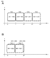
- 2A and 2B are schematic diagrams showing the operation of the time domain and the frequency domain of the two communication methods.
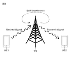
- FIG. 3 is a block diagram for explaining self-interference.
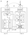
- FIG. 4 is a block diagram showing a configuration of a base station according to an embodiment of the present invention.
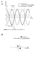
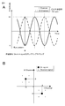
- 5A and 5B are schematic diagrams showing waveform diagrams and complex planes used to explain the effects of self-interference signals.
- 6A and 6B are schematic diagrams showing a waveform diagram and a complex plane used for explaining one embodiment of the present invention.
- FIG. 7 is a schematic diagram for explaining the separation of the self-interference signal and the desired signal in one embodiment of the present invention.
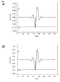
- 8A and 8B are waveform diagrams showing each of the in-phase component and the orthogonal component of the signal transmitted from the base station BS to the user terminal UE2.
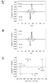
- 9A, 9B and 9C are waveform diagrams showing the in-phase component and the orthogonal component of the self-interference signal received by the base station BS itself as the signal transmitted from the base station BS to the user terminal UE2, and their respective waveform diagrams. It is a schematic diagram which shows on the complex plane of a signal.
- 10A, 10B, and 10C are waveform diagrams showing the in-phase component and the orthogonal component of the desired signal received at the base station BS by the signal transmitted from the user terminal UE1 to the base station BS, and a waveform diagram of these signals.
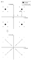
- FIG. 12 is a schematic diagram for explaining the Superposition Constellation formed by the self-interference signal and the desired signal.
- FIG. 13 is a schematic diagram for explaining a process of removing the self-interference signal and separating the desired signal.
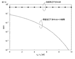
- FIG. 14 is a graph for explaining the simulation result (BER characteristic) of the present invention.
- the base station BS (Base Station) performs bidirectional communication with the user devices UE1 and UE2, respectively.
- the base station BS is actually designed to perform wireless communication with more user terminals. Communication from the user device UE1 or UE2 to the base station BS is called an uplink, and communication from the base station BS to the user device UE1 or UE2 is called a downlink.
- a conventional HD as shown in FIG. 2A, it is necessary to allocate the upper and lower links with each UE to different time slot TSs (or different frequency resources). For example, in FIG.
- uplink communication is performed from the user device UE1 to the base station BS in TS1, uplink communication is performed from the user device UE2 to the base station BS in TS2, and uplink communication is performed from the base station BS to the user device UE1 in TS3.
- Downlink communication is carried out to, and downlink communication is carried out from the base station BS to the user device UE2 in TS4. Therefore, a total of four time slot TSs are used.
- FIG. 2B in IBFD, the spectrum utilization efficiency can be ideally doubled by simultaneously transmitting and receiving the base station BS in the same frequency band. For example, in FIG.
- uplink communication from the user device UE1 to the base station BS and downlink communication from the base station BS to the user device UE2 are simultaneously performed in TS1, and uplink communication from the user device UE2 to the base station BS is performed in TS2.
- Link communication and downlink communication from the base station BS to the user device UE1 are simultaneously performed. Therefore, ideally, a total of two time slot TSs can be used, and the frequency utilization efficiency is up to twice as high.
- IBFD has many advantages as compared with conventional HD, such as solving the hidden terminal problem and reducing traffic congestion.
- the strong self-interference signal (indicated by the broken line) given to the received signal (desired signal) by its own transmission signal significantly deteriorates the reception quality of the desired signal, so IBFD is still in practical use. Has not been reached.
- the present invention solves such a problem.
- the transmission signal that is, self
- the reception signal that is, the desired signal
- FIG. 4 shows an example of a transmitter / receiver configuration in a BS in which the “superimposition modulation feature utilization type signal separation / reception technology” proposed by the present invention is introduced.
- a transmitting unit 1, a transmitting high frequency unit 2, a transmitting antenna 3, a receiving unit 11, a receiving high frequency unit 12, and a receiving antenna 13 are provided.
- the time for training is set in advance. Training may be performed during the default period or during reception.
- the adjustment value obtained by training is held in, for example, a non-volatile memory (not shown).
- the transmission unit 1 is provided with switches 4 and 5 that can be switched between transmission / reception and training.
- the data signal 6 selected by the switches 4 and 5 is transmitted through the transmission high frequency unit 2 and the transmission antenna 3 after the transmission timing is adjusted by the transmission timing adjustment unit 8.
- the transmission timing of the training signal 7 selected by the switches 4 and 5 is adjusted by the transmission timing adjusting unit 8, and the training signal 7 from the transmission timing adjusting unit 8 is transmitted through the transmission high frequency unit 2 and the transmission antenna 3. Will be done.
- the training signal 7 is a signal that has been modulated in the same manner as the transmission signal, and is known data.
- the received signal received by the receiving antenna 13 is processed by the receiving high frequency unit 12 and supplied to the receiving unit 11.
- the transmission unit 1 is provided with switches 14 and 15 that can be switched between transmission / reception and training. In the transmission / reception state, the reception signal selected by the switches 14 and 15 is supplied to the separation unit 16.
- the separation unit 16 has a function of removing the self-interference signal to separate and output a desired signal.
- the training signal is detected by the detection unit 17 from the received signal selected by the switch 15.
- the detected training signal is supplied to the offset calculation unit 18.
- the offset calculation unit 18 calculates the transmission timing offset.
- the transmission timing offset is the time difference between the sampling timing of the received signal and the sampling timing of the transmission signal.
- the sampling timing for data determination is preferably the time when the eye pattern is most open (center time).
- the influence of the transmitted signal (self-interfering signal) on the received signal (desired signal) is determined by the separation unit that separates the self-interfering signal and the desired signal, which will be described later.
- the offset obtained by the offset calculation unit 18 is supplied to the transmission timing adjustment unit 8 of the transmission unit 1, and the transmission timing adjustment unit 8 adjusts the timing of the transmission signal so that the offset disappears.
- the transmission timing adjusting unit 8 adjusts the transmission timing of the transmission signal in consideration of the circuit delay and the like.
- the separation unit 16 that separates the self-interference signal and the desired signal separates the two, and the desired signal is taken out. When the training is completed, the switches 4 and 5 are switched and the transmission / reception operation is performed. Since the transmitted data signal 6 is transmitted via the transmission timing adjusting unit 8, it is assumed that the sampling timings of the received signal and the self-interference signal match, and the separation unit 16 separates the desired signal and the self-interference signal. Is done well.
- an example of a signal transmitted by the base station BS to the user apparatus UE2 is observed.
- an 8-bit information bit string (0,1,1,0,0,1,1,0) is transmitted by QPSK (Quadrature Phase Shift Keying) modulation.
- QPSK Quadrature Phase Shift Keying
- a 2-bit information bit string (1,1) is used for the complex symbol (1 + j)
- a 2-bit information bit string (0,1) is used for the complex symbol (-1 + j)
- the complex symbol (-1-j) is used.
- a QPSK that maps a 2-bit information bit string (0,0) to a complex symbol (1-j) and a 2-bit information bit string (1,0).
- FIG. 5 shows a situation in which the desired signal transmitted by the user apparatus UE1 to the base station BS is also modulated by QPSK, but it is unknown which symbol is being transmitted, and all the locations indicated by x in FIG. 5B are desired.
- the signal transmitted by the base station BS to the user apparatus UE2 is s 1 (t— ⁇ ) ( ⁇ represents the time difference between the sampling timing of the desired signal and the self-interference signal SI), and the desired signal received by the base station BS from the user terminal UE1.
- ⁇ represents the time difference between the sampling timing of the desired signal and the self-interference signal SI
- the signal be r 1 (t).
- the self-interference signal SI is expressed as hs 1 (t ⁇ ).
- FIG. 5A shows the in-phase component and the orthogonal component of the signal hs 1 (t— ⁇ ) transmitted from the base station BS to the user terminal UE 2.
- the horizontal axis represents time, and the unit is sample time.
- the vertical axis represents the signal strength.
- the sampling timing of the desired signal is indicated by a broken line. Sampling at the time when the eye pattern of the received signal is most open (center time) demonstrates the optimum reception performance when determining data. However, there is an offset between this timing and the timing of sampling the desired signal.
- the signal to be transmitted is also sampled at the timing of sampling the desired signal. Therefore, as shown in FIG. 5B, the distribution of the desired signal on the complex plane is random. Therefore, it cannot be demodulated. That is, it becomes unclear where the desired signal exists in the four quadrants of the complex plane, and the desired signal cannot be demodulated by QPSK.
- the timing of the transmission signal is adjusted so that, as shown in FIG. 6A, the time when the eye pattern of the transmission signal is most open (center time) is completely matched, or within an acceptable timing shift. can do. Therefore, as shown in FIG. 6B, in the case of a single carrier, for example, the mixed signal of the self-interference signal and the desired signal is in a state in which the received signal (desired signal) is superposition-coded to the transmitted signal (self-interfering signal). It becomes.
- the constellation (modulated complex signal) of the received signal (desired signal) is received in a state where the bias is added by the amount of the self-interference signal. Therefore, as shown in FIG. 7, the demodulation result of the desired signal can be obtained by subtracting the self-interference signal component on the complex plane and directly demodulating the residual complex signal component in the demodulation procedure of Superposition Coding.
- the processing of the present invention will be described in more detail.
- the signal transmitted by the base station BS to the user apparatus UE2 is s 1 (t— ⁇ ) ( ⁇ represents the time difference between the sampling timing of the desired signal and the self-interference signal SI), and the desired signal received by the base station BS from the user terminal UE1.
- the signal be r 1 (t).
- the self-interference signal SI is expressed as hs 1 (t ⁇ ).
- FIG. 8A shows an in-phase component of the self-interference signal hs 1 (t ⁇ ) received by the base station BS itself for a signal transmitted from the base station BS to the user terminal UE2, and FIG. 8B shows orthogonality of this signal.
- the horizontal axis represents time, and the unit is sample time.
- the vertical axis represents the signal strength. Since we are observing an example of a signal that is transmitted by QPSK-modulating a 4-bit information bit string (0,0,1,1), there are two QPSK-modulated transmission symbols (-1-j, 1 + j). It becomes a complex symbol.
- FIG. 9C shows the signal simultaneously represented in the time domain and the complex plane.
- the time domain waveforms (FIGS. 9A and 9B) are the same as those in FIGS. 8A and 8B.
- the horizontal axis of the complex plane is the in-phase component (I-axis), and the vertical axis thereof is the orthogonal component (Q-axis).
- FIGS. 10A, 10B, and 10C show an example of a signal (desired signal) transmitted from the user terminal UE 1 to the base station BS.
- the transmission information bit string is assumed to be (0,1,1,1), and in that case, the in-phase component and the orthogonal component of the desired signal after QPSK modulation are (-1,1) (1,1).
- the channel coefficient is A 2
- the in-phase component and the orthogonal component of the desired signal received by the base station BS are (-A 2 , A 2 ) (A 2 , A 2 ), which are shown in FIGS. 10A and 10B, respectively. It is indicated by the arrow in.
- FIG. 10C is a complex plane representation of the received desired signal.
- the horizontal axis of the complex plane is the in-phase component (I-axis), and the vertical axis thereof is the orthogonal component (Q-axis).
- the power takes a constant value at the sampling point.
- the magnitude of A 2 Desired signal to power than the self-interference signal is small, 10A, 10B, in FIG. 10C, the amplitude compared to A 1 is a small value A 2.
- the time difference ⁇ between the sampling timings of the desired signal and the self-interference signal SI is 0, the time waveform of the self-interference signal (FIGS. 9A and 9B) and the time waveform of the desired signal (FIGS. 10A and 10B) are added together in a state where the signals match at a certain time.
- FIG. 11A and 11B show the in-phase and orthogonal components of the time waveform as a result of the addition
- each of the in-phase component and the orthogonal component has four possibilities, there are 16 possible existence points (candidates) on the IQ plane.
- white dots show 2 out of 16 candidates.
- the black dot is where the self-interference signal exists.
- FIG. 12 shows all the possibilities.
- black dots represent self-interference signals and x represents a desired signal.
- the self-interference component may be removed on the IQ plane based on the procedure of Superposition coding.
- FIG. 13 shows the process.
- QPSK demodulation is performed on the assumption that all the received signals are self-interference signals, the resulting bit string is QPSK demodulated again, and the estimated self-interference signal component amplitude component A 1 is multiplied to generate a replica signal.
- the replica signal of the generated self-interference signal from the originally received desired signal and the combined signal of the self-interference signal, only the desired signal remains.
- QPSK demodulating this residual component a reception bit string of a desired signal is obtained.
- FIG. 14 shows an example of the communication quality evaluation result by computer simulation when the present invention is applied to the Single Carrier.
- a vertical axis BER in FIG. 14 (bit error rate), the horizontal axis represents E B / N O (communication quality). BER is meant enough that good downward, E B / N O means that good enough toward the right.
- the self-interference signal can be suppressed only about 60 dB to 70 dB, and as a result, the BER becomes high as shown in the horizontal graph in FIG. 14, and it cannot be put into practical use.
- the present invention can be used in combination with existing technology.
- the self-interference signal is 110 dB larger than the desired signal
- the BER as shown by the broken line in FIG. 14 can be realized by combining with the existing technology capable of improving 70 dB. This matches the BER at the time of HD. Therefore, according to the present invention, it can be expected that the requirements in the conventional self-interference canceling technique are relaxed.
- the present invention is not essential to be combined with the existing self-interference canceling technique, and a sufficient effect can be exhibited by itself.
- Transmission timing adjustment unit 11 ... Reception unit, 12 ... Reception high frequency unit 13 ... Reception antenna, 18 ... Transmission timing offset calculation unit
Landscapes
- Engineering & Computer Science (AREA)
- Signal Processing (AREA)
- Computer Networks & Wireless Communication (AREA)
- Noise Elimination (AREA)
- Mobile Radio Communication Systems (AREA)
Abstract
第1のユーザー端末からのデータ受信と、第2のユーザー端末に対するデータ送信を、同じ周波数帯で同時に行なう通信装置において、トレーニング時に、既知のデータからなるトレーニング信号を送信する送信部及びアンテナと、送信信号の送信タイミングを調整する送信タイミング調整部と、自己干渉信号及び所望信号を含む受信信号を受信するアンテナ及びトレーニング信号検出部を含む受信部と、受信信号の受信タイミングとトレーニング信号の送信タイミングのオフセットを計算するオフセット計算部と、自己干渉信号と所望信号を分離する分離部とを備え、オフセット計算部により計算されたオフセットによって、前記送信タイミングと前記受信タイミングがほぼ一致するように、送信タイミング調整部を制御し、分離部によって自己干渉信号と所望信号を分離するようになされた通信装置である。 図4
Description
本発明は、周波数利用効率を高くすることが可能な通信装置および通信方法に関する。
近年、無線通信に対する需要が増加の一途を辿っており、周波数リソースの不足が深刻化している。スペクトル利用効率を改善するために、これまでにも様々な技術が提案されてきた。その一つがIn-Band Full-Duplex(IBFDと適宜称する)である。基地局BS(Base Station)は、複数のユーザー装置UE(User Equipment)と双方向通信を行う。従来のHalf-Duplex(HDと適宜称する)では各UEとの上下リンクをそれぞれ別のタイムスロット(もしくは別の周波数リソース)に割り当てる必要があるが、IBFDではBSが同じ周波数帯で同時送受信することで、スペクトル利用効率を理想的には2倍にできる有望な技術として期待されてきた。また、IBFDは従来のHDと比較して、隠れ端末問題の解決や、トラフィック輻輳の低減など多くの利点も有する。
一方で、自身の送信信号が受信信号(所望信号)に対して与える強力な干渉(Self-Interference,SI、自己干渉と適宜称する)信号が所望信号の受信品質を著しく劣化させるため、IBFDは未だ実用化に至っていない。これを解決するために、これまでにアンテナによるキャンセル技術(非特許文献1参照)、アナログ回路におけるキャンセル技術(非特許文献2参照)、およびデジタル回路におけるキャンセル技術(非特許文献3参照)などの様々な自己干渉キャンセル技術が提案されている。
J. Il Choi,M, Jain, K. Srinivasan,P. Levis, and S. Katti, "Achieving single channel, full duplex wireless communication,"Proceedings of the Sixteenth Annual International Conference on Mobile Computing and Net-working (MobiCom 10), pp. 1-12, Sep. 2010.
D. Bharadia, E. McMilin, and S. Katti, "Full duplex radios," SIGCOMM Com-put. Commun. Rev., Vol. 43, No. 4, pp. 375-386, Aug. 2013.
E. Ahmed and A. M. Eltawil, "All-digital self-interference cancellation technique for full-duplex systems," IEEE Transactions on Wireless Communications, Vol. 14, No. 7, pp. 3519-3532, Jul. 2015.
非特許文献1に記載のものは、アンテナを三つ使用し、二つの送信アンテナ間の距離が大きいことで実用化は難しい問題がある。非特許文献2に記載のものは、サーキュレーターを用いてアナログ自己干渉キャンセルを実装しているが、サーキュレーターのハードウェア規模が大きい問題ある。非特許文献3に記載のものは、二つの同じ受信回路を用いてデジタル自己干渉キャンセルを実装していることで、ハードウェア規模が増大する問題がある。これらの技術では、自己干渉信号と所望信号の混合受信信号の時間波形から自己干渉信号成分の時間波形を直接差し引くことで自己干渉成分のキャンセルを試みる。それらのいくつかは、特定の環境下において十分なキャンセル性能が達成できると報告されているが、実装の複雑さやハードウェア規模の増大、また実現環境が極端に限定されるなど、各技術単体では十分に実用性があるとは言えない。
したがって、本発明の目的は、これらの従来自己干渉キャンセル技術適用後に残留した自己干渉信号をデジタル領域でキャンセルし、周波数利用効率を最大二倍にできることを可能とする通信装置および通信方法を提供することにある。
本発明は、第1のユーザー端末からのデータ受信と、第2のユーザー端末に対するデータ送信を、同じ周波数帯で同時に行なう通信装置において、
トレーニング時に、既知のデータからなるトレーニング信号を送信する送信部及びアンテナと、
送信信号の送信タイミングを調整する送信タイミング調整部と、
自己干渉信号及び所望信号を含む受信信号を受信するアンテナ及びトレーニング信号検出部を含む受信部と、
所望信号の受信タイミングとトレーニング信号の送信タイミングのオフセットを計算するオフセット計算部と、
自己干渉信号と所望信号を分離する分離部とを備え、
オフセット計算部により計算されたオフセットによって、自己干渉信号の受信タイミングと所望信号の受信タイミングがほぼ一致するように、送信タイミング調整部を制御し、分離部によって自己干渉信号と所望信号を分離するようになされた通信装置である。
本発明によれば、小さな回路規模であって、従来の自己干渉キャンセル技術による残留自己干渉をキャンセルし、周波数利用効率を高くすることができる。なお、ここに記載された効果は必ずしも限定されるものではなく、この発明中に記載されたいずれの効果であってもよい。また、以下の説明における例示された効果によりこの発明の内容が限定して解釈されるものではない。
以下、この発明の一実施形態について説明する。なお、以下に説明する一実施形態は、この発明の好適な具体例であり、技術的に好ましい種々の限定が付されているが、この発明の範囲は、以下の説明において、特にこの発明を限定する旨の記載がない限り、これらの実施形態に限定されないものとする。
図1を参照してIBFDについて説明する。基地局BS(Base Station)は、ユーザー装置UE1とUE2とそれぞれ双方向通信を行う。基地局BSは、実際にはより多くのユーザー端末と無線通信を行なうようにされている。ユーザー装置UE1もしくはUE2から基地局BSへの通信を上りリンク、基地局BSからユーザー装置UE1もしくはUE2への通信を下りリンクと呼称する。従来のHDでは、図2Aに示すように、各UEとの上下リンクをそれぞれ別のタイムスロットTS(もしくは別の周波数リソース)に割り当てる必要がある。例えば図2Aでは、TS1においてユーザー装置UE1から基地局BSへの上りリンク通信を実施し、TS2においてユーザー装置UE2から基地局BSへの上りリンク通信を実施し、TS3において基地局BSからユーザー装置UE1への下りリンク通信を実施し、TS4において基地局BSからユーザー装置UE2への下りリンク通信を実施する。したがって合計4つのタイムスロットTSを利用する。これに対して、図2Bに示すように、IBFDでは基地局BSが同じ周波数帯で同時送受信する事で、スペクトル利用効率を理想的には2倍にすることができる。例えば図2Bでは、TS1においてユーザー装置UE1から基地局BSへの上りリンク通信と、基地局BSからユーザー装置UE2への下りリンク通信を同時に実施し、TS2においてユーザー装置UE2から基地局BSへの上りリンク通信と、基地局BSからユーザー装置UE1への下りリンク通信を同時に実施する。したがって理想的には合計2つのタイムスロットTSの利用で済むため、最大二倍の周波数利用効率となる。また、IBFDは従来のHDと比較して、隠れ端末問題の解決や、トラフィック輻輳の低減など多くの利点も有する。
一方で、図3のように自身の送信信号が受信信号(所望信号)に対して与える強力な自己干渉信号(破線で示す)が所望信号の受信品質を著しく劣化させるため、IBFDは未だ実用化に至っていない。本発明は、かかる問題を解決するものである。
本発明では、従来の自己干渉キャンセル技術のように、混合受信信号から直接自己干渉信号成分を時間波形として直接差し引く方式と異なり、BS受信側において受信信号(すなわち所望信号)に送信信号(すなわち自己干渉信号)をそのタイミングを調整した上で重畳して変調し、その重畳信号の変調特徴を用いて受信信号だけを取り出す「重畳変調特徴利用型信号分離受信技術」を提案する。
図4に本発明が提案する、「重畳変調特徴利用型信号分離受信技術」を導入したBSにおける送受信機構成の一例を示す。送信部1、送信高周波部2及び送信アンテナ3と、受信部11、受信高周波部12及び受信アンテナ13が設けられている。予めトレーニングを行なう時が設定されている。トレーニングは、初期設定の期間に行なうようにしてもよいし、受信中に行なうようにしてもよい。トレーニングによって得られた調整値は、例えば不揮発性メモリ(不図示)などに保持される。
送信部1には、送受信時とトレーニング時とで切り替えられる切替器4及び5が設けられている。送受信状態では、切替器4及び5によって選択されたデータ信号6が送信タイミング調整部8において送信タイミングが調整されてから、送信高周波部2及び送信アンテナ3を通じて送信される。トレーニング時では、切替器4及び5によって選択されたトレーニング信号7が送信タイミング調整部8において送信タイミングが調整され、送信タイミング調整部8からのトレーニング信号7が送信高周波部2及び送信アンテナ3を通じて送信される。トレーニング信号7は、送信信号と同様の変調がなされた信号であり、既知のデータである。
受信アンテナ13によって受信された受信信号が受信高周波部12で処理されて受信部11に供給される。送信部1には、送受信時とトレーニング時とで切り替えられる切替器14及び15が設けられている。送受信状態では、切替器14及び15によって選択された受信信号が分離部16に供給される。分離部16は、自己干渉信号を取り除いて所望信号を分離して出力する機能を有する。
トレーニング時では、切替器15によって選択された受信信号から検出部17によってトレーニング信号が検出される。検出されたトレーニング信号がオフセット計算部18に供給される。オフセット計算部18では、送信タイミングのオフセットが計算される。送信タイミングのオフセットは、受信信号のサンプリングタイミングと送信信号のサンプリングタイミングの時間差のことである。一般的にパルス通信において、データ判定のためのサンプリングタイミングは、アイパターンが一番開いている時刻(中央の時刻)とされることが好ましい。受信信号と送信信号のサンプリングタイミングが一致していると、送信信号(自己干渉信号)が受信信号(所望信号)に対して与える影響を、後ほど説明する自己干渉信号と所望信号を分離する分離部16による処理によって、除去もしくは軽減しやすくすることができる。
オフセット計算部18によって得られたオフセットが送信部1の送信タイミング調整部8に対して供給され、送信タイミング調整部8は、オフセットがなくなるように、送信信号のタイミングが調整される。なお、送信タイミング調整部8は、回路遅延等を考慮して送信信号の送出タイミングを調整する。自己干渉信号と所望信号を分離する分離部16によって両者が分離され、所望信号が取り出される。トレーニングが終了すると、切替器4及び5が切替られ、送受信動作がなされる。送信されるデータ信号6が送信タイミング調整部8を介して送信されるので、受信信号と自己干渉信号のサンプリングタイミングが一致したものとされ、分離部16において、所望信号と自己干渉信号の分離処理が良好になされる。
次に、基地局BSがユーザー装置UE2に送信する信号の例を観察する。一例として、8ビットの情報ビット列(0,1,1,0,0,1,1,0)をQPSK(Quadrature Phase Shift Keying)変調で送信する。ここでは、例として複素シンボル(1+j)に2ビットの情報ビット列(1,1)を、複素シンボル(-1+j)に2ビットの情報ビット列(0,1)を、複素シンボル(-1-j)に2ビットの情報ビット列(0,0)を、複素シンボル(1-j)に2ビットの情報ビット列(1,0)をマッピングするQPSKを考える。送信信号が受信されるまでに減衰もしくは増幅される係数をAとすると、QPSK変調された受信シンボルは図5の例では、(-A+jA,A-jA,-A+jA,A-jA)の4つの複素シンボルとなる。また図5では、ユーザー装置UE1が基地局BSに送信する所望信号もQPSKで変調されているが、どのシンボルが送信されているかわからない状況を示しており、図5Bのxで示す場所が全て所望信号の候補となる。基地局BSがユーザー装置UE2に送信する信号をs1(t-τ)(τは所望信号と自己干渉信号SIのサンプリングタイミングの時間差を表す)、基地局BSが受信するユーザー端末UE1からの所望信号をr1(t)とする。この時、自己干渉信号SIは、hs1(t-τ)と表される。ここでhはチャネル係数であり、図5の例ではh=Aである。
図5Aは、基地局BSからユーザー端末UE2に送信する信号hs1(t-τ)の同相成分及び直交成分を表している。図5Aにおいて、横軸が時間を表しており、単位はサンプル時間となる。縦軸は信号の強さを表している。また、所望信号のサンプリングタイミングを破線で示す。受信信号のアイパターンが一番開いている時刻(中央の時刻)において、サンプリングされることがデータ判定の際に最適な受信性能を発揮する。しかしながら、このタイミングと所望信号のサンプリングのタイミングの間にオフセットが存在する。
本発明と異なり、送信信号の送出タイミング調整を行わない場合、所望信号のサンプリングのタイミングで送信する信号もサンプリングされるので、図5Bに示すように、複素平面での所望信号の分布がランダムとなるため復調できない。すなわち、所望信号が複素平面の4個の象限のどこに存在するかが不明となり、所望信号をQPSK復調することができなくなる。
本発明では、送信信号のタイミング調整を行なって、図6Aに示すように、送信信号のアイパターンが一番開いている時刻(中央の時刻)を完全に一致する、もしくは許容できるタイミングずれ以内とすることができる。したがって、図6Bに示すように、自己干渉信号及び所望信号の混合信号は例えばSingle Carrierの場合、送信信号(自己干渉信号)に受信信号(所望信号)がSuperposition Coding(重畳符号化)された状態となる。受信信号(所望信号)のコンスタレーション(変調複素信号)は、自己干渉信号分だけバイアスが付加された状態で受信される。したがって、図7に示すように、Superposition Codingの復調要領で、複素平面上で自己干渉信号成分を差し引き、残留複素信号成分を直接復調することで所望信号の復調結果を得ることができる。
さらに、本発明の処理についてより詳細に説明する。上述したように、基地局BSがユーザー装置UE2に対して、例えば4ビットの情報ビット列(0,0,1,1)をQPSK変調して送信する信号の例を観察する。基地局BSがユーザー装置UE2に送信する信号をs1(t-τ)(τは所望信号と自己干渉信号SIのサンプリングタイミングの時間差を表す)、基地局BSが受信するユーザー端末UE1からの所望信号をr1(t)とする。この時、自己干渉信号SIは、hs1(t-τ)と表される。
図8Aは、基地局BSからユーザー端末UE2に対して送信する信号を、基地局BS自身が受信した自己干渉信号hs1(t-τ)の同相成分を表し、図8Bは、この信号の直交成分を表している。横軸は時間を表しており、単位はサンプル時間となる。縦軸は信号の強さを表している。4ビットの情報ビット列(0,0,1,1)をQPSK変調して送信する信号の例を観察しているため、QPSK変調された送信シンボルは、(-1-j,1+j)の2つの複素シンボルとなる。ここで、チャネル係数h=A1であったとすると、受信される自己干渉信号の同相成分と直交成分は、それぞれ(-A1,A1)(-A1,A1)となり、それぞれ図8A及び図8Bの矢印で示す。パワーは、サンプリングの所では、一定の値をとる。今回の自己干渉信号の場合、大きさA1となる。図8A及び図8Bにおいて、サンプリング点におけるパワーが一定となるのは、送信側でナイキストフィルタのインパルス応答を畳み込む特徴である。
信号を時間領域と複素平面に同時に表したものが図9Cである。時間領域の波形(図9A及び図9B)は、図8A及び図8Bと同じものである。複素平面の横軸が同相成分(I軸)であり、その縦軸が直交成分(Q軸)である。
図10A,図10B,図10Cにユーザー端末UE1から基地局BSに送信する信号(所望信号)の一例を示す。送信情報ビット列は、(0,1,1,1)を想定し、その場合、QPSK変調した後の所望信号の同相成分及び直交成分は、(-1,1)(1,1)となる。チャネル係数がA2であるとすると、基地局BSにおいて受信される所望信号の同相成分及び直交成分は、(-A2,A2)(A2,A2)となり、それぞれ図10A及び図10Bにおける矢印で示す。図10Cは、受信された所望信号を複素平面に表したものである。複素平面の横軸が同相成分(I軸)であり、その縦軸が直交成分(Q軸)である。パワーは、サンプリングの所では、一定の値をとる。この自己干渉信号の場合、大きさA2となる。所望信号が自己干渉信号に比してパワーが小さいために、図10A,図10B,図10Cにおいては、A1に比べて振幅が小さな値A2となっている。
本発明においては、所望信号と自己干渉信号SIのサンプリングタイミングの時間差τを0とするので、自己干渉信号の時間波形(図9A及び図9B)と所望信号の時間波形(図10A及び図10B)は、信号がある時刻で一致した状態で足し合わされる。
図11A及び図11Bは、足し合わされた結果の時間波形の同相成分及び直交成分を表してのり、図11Cは、複素平面上のプロットを示す。τ=0で足し合わせてあるので、情報信号のある所は一致している。信号波形の情報信号のある所の振幅は一定である。よって、足し合わせた波形の情報信号のある所の振幅は、同相成分、及び直交成分のそれぞれで(A1+A2)(A1-A2)(-A1+A2)(-A1-A2)の4個の可能性がある。
同相成分と直交成分がそれぞれ4個の可能性を持つので、IQ平面上では、16個の存在可能性箇所(候補)ができる。図11Cでは、白ドットが16個の候補中の2個を示している。黒ドットは、自己干渉信号の存在する所である。
このようにIQ平面上のConstellationを足し合わせてできた新たなConstellationをSuperposition Constellation と呼ぶことにする。その全部の可能性を示したのが図12である。図12において、黒ドットが自己干渉信号を表し、xが所望信号を表している。このようにして、Superposition Constellation を得た後に所望信号を取り出すためには、IQ平面上でSuperposition codingの要領に基づき自己干渉成分を取り除けばよい。その過程を表したのが図13である。まず受信信号が全て自己干渉信号だと仮定してQPSK復調を行い、その結果得られたビット列を再度QPSK復調し、推定した自己干渉信号成分の振幅成分A1を乗じ、レプリカ信号を生成する。この生成した自己干渉信号のレプリカ信号を、元々受信していた所望信号と自己干渉信号の合成信号から差し引くことで、所望信号のみが残る。この残留成分をQPSK復調することで、所望信号の受信ビット列を得る。
図14に本発明をSingle Carrierに適用した場合の計算機シミュレーションによる通信品質評価結果の一例を示す。図14の縦軸がBER(ビットエラーレート)であり、横軸がEB /NO (通信品質)である。BERは、下方に向かうほど良好なことを意味し、EB/NO は、右側に向かうほど良好なことを意味する。
例えばIBFDにおいては、自己干渉信号を110dB程度抑えないと、所望のBERが得られないとされている。既存の提案されている自己干渉信号の抑圧技術では、このような性能を得ることが難しかった。例えば60dB~70dB程度しか自己干渉信号を抑圧することができず、その結果、図14において、水平のグラフのように、高いBERとなり、実用に供することができなかった。
本発明は、既存の技術と組み合わせて使用することできる。例えば所望信号に対して自己干渉信号が110dB大きかった時に、70dB改善を行なうことができる既存の技術と組み合わせることによって、図14において破線で示すようなBERを実現できる。これはHD時のBERと一致する。したがって、本発明によれば、従来の自己干渉キャンセル技術における要求条件を緩和させることが期待できる。但し、本発明は、既存の自己干渉キャンセル技術と組み合わせることを必須とするものではなく、単独でも十分な効果を発揮することができる。
以上、本発明の実施形態について具体的に説明したが、上述の各実施形態に限定されるものではなく、本発明の技術的思想に基づく各種の変形が可能である。
1・・・送信部、2・・・送信高周波部
3・・・送信アンテナ、6・・・データ信号、
7・・・トレーニング信号、8・・・送信タイミング調整部
11・・・受信部、12・・・受信高周波部
13・・・受信アンテナ、
18・・・送信タイミングオフセット計算部
3・・・送信アンテナ、6・・・データ信号、
7・・・トレーニング信号、8・・・送信タイミング調整部
11・・・受信部、12・・・受信高周波部
13・・・受信アンテナ、
18・・・送信タイミングオフセット計算部
Claims (5)
- 第1のユーザー端末からのデータ受信と、第2のユーザー端末に対するデータ送信を、同じ周波数帯で同時に行なう通信装置において、
トレーニング時に、既知のデータからなるトレーニング信号を送信する送信部及びアンテナと、
送信信号の送信タイミングを調整する送信タイミング調整部と、
自己干渉信号及び所望信号を含む受信信号を受信するアンテナ及びトレーニング信号検出部を含む受信部と、
前記受信信号の受信タイミングと前記トレーニング信号の送信タイミングのオフセットを計算するオフセット計算部と、
自己干渉信号と所望信号を分離する分離部とを備え、
前記オフセット計算部により計算されたオフセットによって、前記送信タイミングと前記受信タイミングがほぼ一致するように、前記送信タイミング調整部を制御し、前記分離部によって前記自己干渉信号と前記所望信号を分離するようになされた通信装置。 - トレーニング時が予め設定されている請求項1に記載の通信装置。
- 前記所望信号に比して前記自己干渉信号がより大きい請求項1に記載の通信装置。
- アナログ又はデジタル方式の自己干渉信号キャセル装置が組み合わされた請求項1に記載の通信装置。
- 第1のユーザー端末からのデータ受信と、第2のユーザー端末に対するデータ送信を、同じ周波数帯で同時に行なう通信方法において、
トレーニング時に、既知のデータからなるトレーニング信号を送信し、
送信タイミング調整部によって送信信号の送信タイミングを調整し、
自己干渉信号及び所望信号を含む受信信号を受信し、
オフセット計算部によって前記受信信号の受信タイミングと前記トレーニング信号の送信タイミングのオフセットを計算し、
分離部によって自己干渉信号と所望信号を分離し、
前記オフセット計算部により計算されたオフセットによって、前記送信タイミングと前記受信タイミングがほぼ一致するように、前記送信タイミング調整部を制御し、前記分離部によって前記自己干渉信号と前記所望信号を分離する通信方法。
Applications Claiming Priority (2)
| Application Number | Priority Date | Filing Date | Title |
|---|---|---|---|
| JP2020-062107 | 2020-03-31 | ||
| JP2020062107A JP7673366B2 (ja) | 2020-03-31 | 2020-03-31 | 通信装置および通信方法 |
Publications (1)
| Publication Number | Publication Date |
|---|---|
| WO2021199812A1 true WO2021199812A1 (ja) | 2021-10-07 |
Family
ID=77929591
Family Applications (1)
| Application Number | Title | Priority Date | Filing Date |
|---|---|---|---|
| PCT/JP2021/007354 Ceased WO2021199812A1 (ja) | 2020-03-31 | 2021-02-26 | 通信装置および通信方法 |
Country Status (2)
| Country | Link |
|---|---|
| JP (1) | JP7673366B2 (ja) |
| WO (1) | WO2021199812A1 (ja) |
Citations (2)
| Publication number | Priority date | Publication date | Assignee | Title |
|---|---|---|---|---|
| US20190327070A1 (en) * | 2018-04-24 | 2019-10-24 | Electronics And Telecommunications Research Institute | Method and apparatus for canceling self interference signal in communication system |
| JP2019193226A (ja) * | 2018-04-27 | 2019-10-31 | 株式会社Nttドコモ | ユーザ端末および無線基地局 |
-
2020
- 2020-03-31 JP JP2020062107A patent/JP7673366B2/ja active Active
-
2021
- 2021-02-26 WO PCT/JP2021/007354 patent/WO2021199812A1/ja not_active Ceased
Patent Citations (2)
| Publication number | Priority date | Publication date | Assignee | Title |
|---|---|---|---|---|
| US20190327070A1 (en) * | 2018-04-24 | 2019-10-24 | Electronics And Telecommunications Research Institute | Method and apparatus for canceling self interference signal in communication system |
| JP2019193226A (ja) * | 2018-04-27 | 2019-10-31 | 株式会社Nttドコモ | ユーザ端末および無線基地局 |
Non-Patent Citations (2)
| Title |
|---|
| HASEGAWA, TSUYOSHI: "Study of Full-Duplex OFDM Transmitting Timing Control for 5G Wireless Communication System", LECTURE PROCEEDINGS 1 OF THE 2015 COMMUNICATION SOCIETY CONFERENCE OF IEICE, 25 August 2015 (2015-08-25), pages 265 * |
| QIAO GANG; GAN SHUWEI; LIU SONGZUO; SONG QINGJUN: "Self-Interference Channel Estimation Algorithm Based on Maximum-Likelihood Estimator in In-Band Full-Duplex Underwater Acoustic Communication System", IEEE ACCESS, IEEE, USA, vol. 6, 1 January 1900 (1900-01-01), USA , pages 62324 - 62334, XP011704797, DOI: 10.1109/ACCESS.2018.2875916 * |
Also Published As
| Publication number | Publication date |
|---|---|
| JP2021164023A (ja) | 2021-10-11 |
| JP7673366B2 (ja) | 2025-05-09 |
Similar Documents
| Publication | Publication Date | Title |
|---|---|---|
| CN108028669B (zh) | 在数字混沌协作网络中通信数据的方法和设备 | |
| AU2009284653B2 (en) | Systems devices and methods for training sequence transmission and reception | |
| KR20060129100A (ko) | 단일 안테나 간섭 소거를 위한 i/q 다중 입력 다중 출력검출 | |
| EP4681351A1 (en) | Transmitter for a satellite communication system | |
| US6373903B1 (en) | Apparatus and method for increasing the effective data rate in communication systems utilizing phase modulation | |
| Ju et al. | Achievable-rate-enhancing self-interference cancellation for full-duplex communications | |
| CN110741582A (zh) | 发送装置、接收装置以及无线通信系统 | |
| Mishra et al. | Impact of hardware impairments on TWRN and OWRN AF relaying systems with imperfect channel estimates | |
| JP7673366B2 (ja) | 通信装置および通信方法 | |
| Alsmadi et al. | Effect of generalized improper Gaussian noise and in-phase/quadrature-phase imbalance on quadrature spatial modulation | |
| CN100590985C (zh) | 多层载波离散多音通信技术 | |
| US20170117974A1 (en) | RF Signal Separation And Suppression System And Method | |
| US9954574B2 (en) | Spreading sequence system for full connectivity relay network | |
| Neelam | Distributed interference alignment precoding and detection for mu-mimo otsm downlink in time-varying channels | |
| KR101944506B1 (ko) | 기지국에서의 상향 링크 신호 검출 방법 | |
| US8477890B2 (en) | Geometric detector for communicating through constant modulus (CM) interferers | |
| Zhang et al. | On the Uplink Performance of Multi-User MC-CDMA Satellite-Terrestrial Deliveries | |
| Liu et al. | Self-interference cancellation utilizing superposition modulation technique for single carrier full-duplex system | |
| JP4177879B1 (ja) | 受信装置、送信装置および無線通信システム | |
| Yang et al. | Blind source separation-based multi-user detection for multi-antenna QAM receivers with I/Q imbalances | |
| CN101860391A (zh) | 多层载波离散多音通信技术 | |
| US7254181B2 (en) | Transmitting apparatus and method, receiving apparatus and method, and transmitting and receiving apparatus and method | |
| CN102983893B (zh) | 多层载波离散多音通信系统和方法 | |
| US11817989B2 (en) | RF signal separation and suppression system and method | |
| Erić et al. | A solution to coexistence of OFDM and FH signals based on principles of cognitive radio implemented on USRP N210 platform |
Legal Events
| Date | Code | Title | Description |
|---|---|---|---|
| 121 | Ep: the epo has been informed by wipo that ep was designated in this application |
Ref document number: 21780096 Country of ref document: EP Kind code of ref document: A1 |
|
| DPE1 | Request for preliminary examination filed after expiration of 19th month from priority date (pct application filed from 20040101) | ||
| NENP | Non-entry into the national phase |
Ref country code: DE |
|
| 122 | Ep: pct application non-entry in european phase |
Ref document number: 21780096 Country of ref document: EP Kind code of ref document: A1 |