WO2021199768A1 - 電子機器 - Google Patents
電子機器 Download PDFInfo
- Publication number
- WO2021199768A1 WO2021199768A1 PCT/JP2021/006194 JP2021006194W WO2021199768A1 WO 2021199768 A1 WO2021199768 A1 WO 2021199768A1 JP 2021006194 W JP2021006194 W JP 2021006194W WO 2021199768 A1 WO2021199768 A1 WO 2021199768A1
- Authority
- WO
- WIPO (PCT)
- Prior art keywords
- information
- electronic device
- fingerprint
- display
- authentication
- Prior art date
- Legal status (The legal status is an assumption and is not a legal conclusion. Google has not performed a legal analysis and makes no representation as to the accuracy of the status listed.)
- Ceased
Links
Images








Classifications
-
- G—PHYSICS
- G06—COMPUTING OR CALCULATING; COUNTING
- G06V—IMAGE OR VIDEO RECOGNITION OR UNDERSTANDING
- G06V40/00—Recognition of biometric, human-related or animal-related patterns in image or video data
- G06V40/10—Human or animal bodies, e.g. vehicle occupants or pedestrians; Body parts, e.g. hands
- G06V40/12—Fingerprints or palmprints
- G06V40/13—Sensors therefor
- G06V40/1318—Sensors therefor using electro-optical elements or layers, e.g. electroluminescent sensing
-
- A—HUMAN NECESSITIES
- A61—MEDICAL OR VETERINARY SCIENCE; HYGIENE
- A61B—DIAGNOSIS; SURGERY; IDENTIFICATION
- A61B5/00—Measuring for diagnostic purposes; Identification of persons
- A61B5/117—Identification of persons
- A61B5/1171—Identification of persons based on the shapes or appearances of their bodies or parts thereof
- A61B5/1172—Identification of persons based on the shapes or appearances of their bodies or parts thereof using fingerprinting
-
- G—PHYSICS
- G06—COMPUTING OR CALCULATING; COUNTING
- G06F—ELECTRIC DIGITAL DATA PROCESSING
- G06F21/00—Security arrangements for protecting computers, components thereof, programs or data against unauthorised activity
- G06F21/30—Authentication, i.e. establishing the identity or authorisation of security principals
- G06F21/31—User authentication
- G06F21/32—User authentication using biometric data, e.g. fingerprints, iris scans or voiceprints
-
- G—PHYSICS
- G06—COMPUTING OR CALCULATING; COUNTING
- G06F—ELECTRIC DIGITAL DATA PROCESSING
- G06F3/00—Input arrangements for transferring data to be processed into a form capable of being handled by the computer; Output arrangements for transferring data from processing unit to output unit, e.g. interface arrangements
- G06F3/01—Input arrangements or combined input and output arrangements for interaction between user and computer
- G06F3/048—Interaction techniques based on graphical user interfaces [GUI]
- G06F3/0487—Interaction techniques based on graphical user interfaces [GUI] using specific features provided by the input device, e.g. functions controlled by the rotation of a mouse with dual sensing arrangements, or of the nature of the input device, e.g. tap gestures based on pressure sensed by a digitiser
- G06F3/0488—Interaction techniques based on graphical user interfaces [GUI] using specific features provided by the input device, e.g. functions controlled by the rotation of a mouse with dual sensing arrangements, or of the nature of the input device, e.g. tap gestures based on pressure sensed by a digitiser using a touch-screen or digitiser, e.g. input of commands through traced gestures
-
- G—PHYSICS
- G06—COMPUTING OR CALCULATING; COUNTING
- G06Q—INFORMATION AND COMMUNICATION TECHNOLOGY [ICT] SPECIALLY ADAPTED FOR ADMINISTRATIVE, COMMERCIAL, FINANCIAL, MANAGERIAL OR SUPERVISORY PURPOSES; SYSTEMS OR METHODS SPECIALLY ADAPTED FOR ADMINISTRATIVE, COMMERCIAL, FINANCIAL, MANAGERIAL OR SUPERVISORY PURPOSES, NOT OTHERWISE PROVIDED FOR
- G06Q30/00—Commerce
- G06Q30/06—Buying, selling or leasing transactions
- G06Q30/0601—Electronic shopping [e-shopping]
- G06Q30/0641—Electronic shopping [e-shopping] utilising user interfaces specially adapted for shopping
-
- G—PHYSICS
- G06—COMPUTING OR CALCULATING; COUNTING
- G06T—IMAGE DATA PROCESSING OR GENERATION, IN GENERAL
- G06T1/00—General purpose image data processing
-
- G—PHYSICS
- G06—COMPUTING OR CALCULATING; COUNTING
- G06V—IMAGE OR VIDEO RECOGNITION OR UNDERSTANDING
- G06V40/00—Recognition of biometric, human-related or animal-related patterns in image or video data
- G06V40/10—Human or animal bodies, e.g. vehicle occupants or pedestrians; Body parts, e.g. hands
- G06V40/12—Fingerprints or palmprints
- G06V40/1365—Matching; Classification
-
- G—PHYSICS
- G06—COMPUTING OR CALCULATING; COUNTING
- G06V—IMAGE OR VIDEO RECOGNITION OR UNDERSTANDING
- G06V40/00—Recognition of biometric, human-related or animal-related patterns in image or video data
- G06V40/10—Human or animal bodies, e.g. vehicle occupants or pedestrians; Body parts, e.g. hands
- G06V40/15—Biometric patterns based on physiological signals, e.g. heartbeat, blood flow
-
- G—PHYSICS
- G06—COMPUTING OR CALCULATING; COUNTING
- G06V—IMAGE OR VIDEO RECOGNITION OR UNDERSTANDING
- G06V40/00—Recognition of biometric, human-related or animal-related patterns in image or video data
- G06V40/60—Static or dynamic means for assisting the user to position a body part for biometric acquisition
- G06V40/67—Static or dynamic means for assisting the user to position a body part for biometric acquisition by interactive indications to the user
Definitions
- This disclosure relates to electronic devices.
- the optical fingerprint sensor had to keep the finger stationary for a predetermined time when acquiring the fingerprint, which was not convenient in terms of UI. Further, in a terminal logged in by fingerprint authentication, subsequent operations are often possible without fingerprint authentication or the like. For example, it is often possible to make a purchase by credit card payment from a browser after performing personal authentication by fingerprint once, and there is also a security problem.
- One aspect of the present disclosure provides an electronic device that realizes fingerprint authentication during a swipe operation of a display.
- the electronic device includes a display, an optical fingerprint sensor, and an information processing unit.
- the display includes a display surface having light emitting pixels in an array in a first direction and a second direction intersecting the first direction.
- the optical fingerprint sensor has light receiving elements in an array in the first direction and the second direction on the side opposite to the display surface of the display in the third direction intersecting the first direction and the second direction.
- An image pickup device is provided, and fingerprint information that moves in contact with the display is acquired.
- the information processing unit acquires the corrected corrected fingerprint information from the fingerprint information acquired by the optical fingerprint sensor.
- the information processing unit may correct the fingerprint information acquired during an operation including at least a finger swipe operation.
- a touch panel that senses contact information with respect to the display may be further provided, and the information processing unit may estimate the operating speed from the contact information and acquire the corrected fingerprint information based on the operating speed.
- the information processing unit may select one fingerprint information from the fingerprint information of a plurality of frames, and aggregate the fingerprint information of another frame into the selected fingerprint information.
- the information processing unit may determine the exposure time of the optical fingerprint sensor based on the estimated operating speed.
- the information processing unit may determine the reading direction of the image sensor in the optical fingerprint sensor based on the estimated direction of the operating speed.
- an instruction to slow down the swipe operation may be output.
- the instruction of the speed of the swipe operation may be output to the display.
- the instruction may display a speed guide on the display.
- the output that the speed is too fast may be at least one of the output to the display, the output by sound, or the output by vibration.
- the information processing unit may shorten the exposure time of the optical fingerprint sensor when the speed is faster than a predetermined speed.
- the light emitting pixel may output light having a different wavelength on the display surface side of the light receiving element, and the light receiving element may acquire the fingerprint information based on the reflected light having a different wavelength.
- a polarizing filter may be provided between the light receiving element and the display surface, and the light receiving element may sense polarized light through the polarizing filter.
- a filter for acquiring the state of hemoglobin may be provided between the light receiving element and the display surface, and the information processing unit may acquire information on the hemoglobin and perform biometric authentication.
- the information processing unit may perform biometric authentication based on the information on the temporal shape change of the finger in contact with the display surface.
- the light receiving element may detect movements on a plurality of fingers.
- the information processing unit may execute the fingerprint authentication by using a combination of a plurality of fingers in the movement of a plurality of fingers.
- the combination of multiple fingers may be different based on the required authentication accuracy.
- the information processing unit may detect finger information and accumulate the fingerprint information while the authentication is being executed or during the time when the authentication is not being executed.
- the information processing unit may accumulate changes in the finger to improve the authentication accuracy.
- the information processing unit may acquire and store the fingerprint information on a finger other than the unregistered finger.
- the light receiving element may be provided with a larger number of elements in a direction intersecting the direction of the swipe operation than the number of elements in the direction of the swipe operation.
- the light receiving element may be provided with a number of elements in a direction intersecting the direction of the swipe operation, which is more than twice the number of elements in the direction of the swipe operation.
- the display may display a guide for executing the swipe operation in a direction intersecting a direction in which many light receiving elements are provided.
- the area where the light receiving element is provided may be displayed on the display, and the product information and the purchase button may be arranged so as to pass through the area.
- An interface that enables the purchase of the product by swiping the product information from the product information to the purchase button may be provided, and the purchase information is sent to the server based on the result of the fingerprint authentication. May be sent.
- a dynamic object may be displayed on the display so as to include an area provided with the light receiving element.
- the shape of the object may change when the user's finger touches it.
- the light emitting state of the object may change when the user's finger touches it.
- the light emitting state may be changed so as to be suitable for acquiring the fingerprint information.
- the object may dynamically change based on the fingerprint information acquisition status or the personal authentication status after the user's finger has passed.
- a tilt detection unit that detects the tilt of the display from the horizontal direction may be further provided, or the fingerprint information may be authenticated based on the tilt detected by the tilt detection unit.
- the optical fingerprint sensor may acquire the fingerprint information at a frame rate higher than the transfer rate to the information processing unit, and when the fingerprint information has an information amount equal to or more than a predetermined information amount, the fingerprint information is obtained. It may be transferred to the information processing unit.
- the imaging speed of the optical fingerprint sensor may be a frame rate of 100 FPS (Frame per Second) or higher.
- the optical fingerprint sensor may estimate the amount of data included in the fingerprint information, and when the amount of data exceeds a predetermined value, the fingerprint information may be transferred to the information processing unit.
- the optical fingerprint sensor may estimate the amount of data by image analysis.
- the optical fingerprint sensor may estimate the amount of data based on the information on the touch panel.
- the block diagram which shows an example of the structure of the electronic device which concerns on one Embodiment.
- the signal to be acquired is described as image information or imaging information, but the image information and imaging information are broadly defined concepts, and one frame in a still image, a moving image, or a moving image. It is a concept that includes images and the like. Further, “greater than” and “less than” may be read as “greater than or equal to” and “less than or equal to”, respectively.
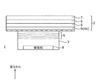
- FIG. 1 is a diagram schematically showing an electronic device according to an embodiment. Further, FIG. 2 is a diagram schematically showing a cross section of the electronic device according to the embodiment.
- the electronic device 1 is, for example, an arbitrary device having a display function and a shooting function, such as a smartphone, a mobile phone, a tablet terminal, and a personal computer.
- the electronic device 1 includes a display unit 2 and a camera module 3.
- the display screen 1a extends close to the external size of the electronic device 1, and the width of the bezel 1b around the display screen 1a can be reduced to, for example, several mm or less. It is possible.
- Many electronic devices 1 include a fingerprint authentication unit in the bezel 1b, but in the present embodiment, the camera module 3 is provided in the display screen 1a as shown by the dotted line. As shown in the left figure, the width of the bezel 1b can be narrowed by providing the camera module 3 for taking a picture for fingerprint authentication on the back side of the display screen 1a.
- the camera module 3 is arranged on the back surface side of the display screen 1a near the center, but the position is not limited to this figure if it is the back surface of the display screen 1a.
- the camera module 3 may be arranged near the peripheral edge of the display screen 1a, or may be arranged below the center of the right figure.
- the place may be arranged at a plurality of places instead of one place.
- the display unit 2 and the camera module 3 are provided on one surface of the electronic device 1, but the present invention is not limited to this.
- the display unit 2 and the camera module 3 may be provided on both sides of the electronic device 1.
- the display unit 2 is a structure in which a display panel 4, a circularly polarizing plate 5, a touch panel 6, and a cover glass 7 are laminated as a display optical system.
- the arrangement of these is not limited, and may be appropriately replaced, two or more of the same configurations may exist, or even another configuration may be included.
- the display panel 4 may be provided with, for example, an OLED (Organic Light Emitting Diode), a liquid crystal display, a MicroLED, and other light emitting elements based on a display principle in an array.
- the light emitting elements are provided in an array in a plane including the first direction and the second direction.
- the display panel 4 such as OLED is composed of a plurality of layers.
- a member having a low transmittance, such as a color filter layer, is often arranged on the display panel 4.
- a through hole may be formed in the member having a low transmittance in the display panel 4 according to the arrangement location of the camera module 3. If the subject light passing through the through hole is incident on the camera module 3, the image quality of the image captured by the camera module 3 can be improved.
- the circularly polarizing plate 5 is provided to reduce glare or enhance the visibility of the display screen 1a even in a bright environment.
- a touch sensor is incorporated in the touch panel 6. There are various types of touch sensors such as a capacitance type, a resistance film type, and a pressure sensitive type, and any method may be used. Further, the touch panel 6 and the display panel 4 may be integrated.
- the cover glass 7 is provided to protect the display panel 4 and the like. Each of these elements may be adhered with an adhesive that has less optical effect.
- the camera module 3 includes an imaging unit 8 and an optical system 9.
- the optical system 9 is arranged on the incident surface side of the light of the imaging unit 8, that is, on the side close to the display unit 2, and collects the light that has passed through the display unit 2 on the imaging unit 8.
- the optical system 9 may include one or more lenses.
- the imaging unit 8 operates as an optical fingerprint sensor to acquire user fingerprint information.
- the imaging unit 8 that operates as an optical fingerprint sensor includes a plurality of photoelectric conversion units.
- a lens is arranged in each photoelectric conversion unit. In this lens, the light appropriately emitted from the optical system 9 to the imaging unit 8 is received by the photoelectric conversion unit constituting each pixel.
- the photoelectric conversion unit photoelectrically converts the light incident on the display unit 2.
- the photoelectric conversion unit may be a CMOS (Complementary Metal-Oxide-Semiconductor Field-Effect Transistor) sensor or a CCD (Charge Coupled Device) sensor.
- the photoelectric conversion unit is provided in an array, for example, in a plane including the first direction and the second direction. Further, the photoelectric conversion units may be provided in an array along the first direction and the second direction.
- the light receiving element of the photoelectric conversion unit is provided as an array of light receiving pixels along the same direction as the light emitting pixels of the display unit.
- the photoelectric conversion unit may be provided with a photodiode or may be provided with an organic photoelectric conversion film.
- the plurality of photoelectric conversion units can be arranged by any method.
- the arrangement method of the plurality of photoelectric conversion units may be, for example, a Bayer arrangement, an interline arrangement, a checkered arrangement, a stripe arrangement, or the like. It may be an array of.
- the output value of the photoelectric conversion unit or the value obtained by predetermined conversion based on this output value is referred to as a light receiving pixel value.
- the fingerprint information of the user is acquired at the timing when the finger passes through the area where the camera module 3 of the display exists, and personal authentication is executed using this fingerprint information.
- the camera module 3 swipes, flicks, and wipes at the timing of dragging the product image to the purchase button. Get fingerprint information from the same finger. This acquisition is performed using a rolling shutter, as will be described later. Further, the camera module 3 executes the operation of the rolling shutter at an appropriate exposure time.
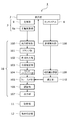
- FIG. 3 is a diagram showing an example of a block diagram of the electronic device 1 according to the present embodiment.
- the inside of the display unit 2 shown in FIGS. 1 and 2 is omitted.
- the electronic device 1 includes an information processing unit 10 and a storage unit 11 that output information from the camera module 3 and the touch panel 6 described above and execute this information processing.
- the imaging unit 8 of the camera module 3 includes a photoelectric conversion unit 8a (photoelectric conversion element).
- the information sensed by the photoelectric conversion unit 8a is transferred to the information processing unit 10 at the timing of each line, for example.
- the information processing unit 10 is configured to include, for example, a CPU (Central Processing Unit), an ASIC (Application Specific Integrated Circuit), an FPGA (Field Programmable Gate Array), and the like. As described below, the information processing unit 10 may be divided into blocks that perform a part or all of various operations, and information processing by software is concretely performed by a CPU for a part or all of each operation. It may be realized as a target.
- a CPU Central Processing Unit
- ASIC Application Specific Integrated Circuit
- FPGA Field Programmable Gate Array
- the storage unit 11 includes, for example, various memories, storages, and the like.
- information such as programs and data required for the electronic device 1 to operate may be stored non-temporarily.
- the memory may include a temporary storage area such as a cache area.
- the information processing unit 10 includes an A / D conversion unit 100, a clamp unit 101, a color-coded output unit 102, a defect correction unit 103, a linear matrix unit 104, a frame memory 105, an authentication unit 106, and an output unit. It includes 107, a speed detection unit 108, a correction amount calculation unit 109, and a correction unit 110.
- the frame memory 105 may be provided as a part of the storage unit 11 instead of the information processing unit 10.
- the A / D conversion unit 100 converts an analog signal based on the electric charge received and stored by the photoelectric conversion unit 8a into a digital signal for each pixel.
- the A / D conversion unit 100 outputs the converted digital signal as image data.
- the clamp unit 101 defines, for example, a black level, and the specified black level is subtracted from the image data output from the A / D conversion unit 100 and output.
- the clamp unit 101 may set the ground level for each photoelectric conversion element provided in the pixel. In this case, the ground correction of the signal value is executed based on the ground level set for each acquired photoelectric conversion element. do.
- the color-coded output unit 102 outputs sub-pixel image data for each color, for example, when the photoelectric conversion unit 8a acquires an analog signal for each color.
- the photoelectric conversion unit 8a is provided with, for example, R (red), G (green), B (blue) color filters and the like. Each photoelectric conversion unit 8a outputs the sensing information for each color by these filters and the like. Instead of the photoelectric conversion unit 8a being provided with a color filter, the photoelectric conversion unit 8a may acquire an analog signal for each color by the organic photoelectric conversion film.
- the clamp unit 101 adjusts the ground level based on these filters, and the color-coded output unit 102 outputs the signal output by the clamp unit 101 by color. No color information is added to the analog signal acquired by the photoelectric conversion unit 8a. Therefore, the color-coded output unit 102 may store data on colors arranged for each light receiving element in the photoelectric conversion unit 8a, and output each color based on this data.
- the photoelectric conversion unit 8a may be provided with a filter for acquiring a complicated spectrum such as an element that receives near-infrared light and a plasmon filter. In these cases, it is difficult to express as mere color information, but the color-coded output unit 102 may process by associating these information with the wavelength information as long as it can be classified by the wavelength of light. In such a case, the color-coded output unit 102 may process the wavelength information as information having a range.
- the defect correction unit 103 corrects defects in the image data. Defects in image data occur, for example, due to missing pixels or missing information due to defects in the photoelectric conversion element provided in the pixels, or missing information due to saturation of light in the optical system 9.
- the defect correction unit 103 may execute the defect correction process by interpolating based on, for example, information on surrounding pixels or information on peripheral pixels having the same color information.
- the linear matrix unit 104 reproduces colors by executing matrix operations on color information.
- the linear matrix unit 104 obtains desired spectroscopy by, for example, performing calculations on a plurality of wavelengths.
- the linear matrix unit 104 may execute, for example, an output suitable for detecting skin color. Further, the linear matrix unit 104 may execute the calculation so as to output the output suitable for the detection of the yellow to red wavelength region in order to acquire the biometric authentication information of the vein or the like.
- the frame memory 105 may be provided, for example, as a part of the storage unit 11.
- the frame memory 105 temporarily stores the information acquired from the photoelectric conversion unit 8a after the above processing.
- the information processing unit 10 performs various above-mentioned processes on the fingerprint information acquired in the frame memory 105 at the same timing, and finally saves the fingerprint information as a single image data color-reproduced by the linear matrix unit 104.
- the authentication unit 106 executes personal authentication using the fingerprint information stored in the frame memory 105. For example, this personal authentication is executed by extracting the feature points in the fingerprint data and comparing the extracted feature points with the authentication information stored in the storage unit 11. Further, the authentication unit 106 may execute biometric authentication for spoofing prevention based on not only RGB information but also, for example, near-infrared light receiving information and information acquired via a plasmon filter. For example, biometric authentication is executed depending on whether or not the wavelength information corresponding to hemoglobin in the data stored in the frame memory 105 is normally acquired. These may be determined by statistical processing such as feature points, or as another example, authentication may be performed using a neural network model trained by machine learning.
- the authentication unit 106 stores the fingerprint information of a specific user acquired in advance in the storage unit 11. Personal authentication is executed based on this stored user information.
- the fingerprint information of the multiple users should be stored appropriately.
- the stored fingerprint information may be an image of each fingerprint information or the information of feature points acquired from each fingerprint information may be encrypted.
- the output unit 107 outputs the authentication result by the authentication unit 106. For example, in the case of shopping by e-commerce or the like, it may be transmitted to a server or the like so that payment processing is performed based on the authentication result. In this way, the output unit 107 may transmit the authentication result using wireless communication. Further, as another example, the authentication result such as fingerprint authentication may be used instead of the authentication by the password or the like in the electronic device 1.
- the speed detection unit 108 acquires the speed of the user's finger movement at the timing when the camera module 3 acquires the fingerprint image, for example, based on the detection information of the touch panel 6. That is, when the user swipes, the camera module 3 acquires fingerprint information from the received light information, and the touch panel 6 acquires finger speed information from the sensing information. For example, the speed detection unit 108 acquires the finger speed based on the amount of movement of the user's finger area detected by the touch panel 6 within a predetermined time.
- the speed detection unit 108 acquires information for speed detection from the touch panel 6 when, for example, a user's finger touches the touch screen at the timing of authentication.
- the speed detection unit 108 acquires, for example, the detection information of the touch panel 6 at a certain time and the detection information of the touch panel 6 after a predetermined time when the user's finger moves.
- the sensing information of the touch panel 6 may be acquired from the center point of the finger region, for example, the position of the center of gravity when the finger region is sensed.
- the position of the center of gravity can be obtained by calculating, for example, the averaging of the points in the sensing region in the first direction and the second direction, respectively.
- the speed detection unit 108 detects the swipe speed of the user's finger by obtaining the position of the center of gravity after a certain time and a predetermined time.
- the correction amount calculation unit 109 acquires a correction amount based on the speed detected by the speed detection unit 108. Based on this correction amount, image processing may be performed on the fingerprint information stored in the frame memory 105. This image processing is, for example, image processing based on motion blur. A PSF may be generated based on the finger speed and the shutter speed, and deconvolution filtering may be performed on the fingerprint information.
- the correction unit 110 corrects the image data stored in the frame memory 105. This correction is executed based on the correction amount calculated by the correction amount calculation unit 109. The calculation of the correction amount by the correction amount calculation unit 109 and the correction by the correction unit 110 will be described in detail later.
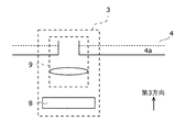
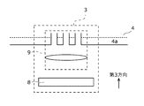
- FIG. 4A is a diagram for explaining the relationship between the camera module 3 and the display panel 4 in FIG. 1 in more detail.
- the camera module 3 includes, for example, an imaging unit 8 and an optical system 9.
- the optical system 9 is arranged on the incident surface side of the light of the imaging unit 8, that is, on the side closer to the display unit 2.
- the light transmitted through the display surface of the display unit 2 is propagated to the image pickup unit 8 by the optical system 9.
- the imaging unit 8 may include, for example, a photoelectric conversion unit 8a such as a photodiode shown in FIG.
- the light that has been condensed, refracted, diffused, etc. by the optical system 9 and propagated is received by the photoelectric conversion unit 8a provided in the imaging unit 8 and output as an analog signal.
- the photoelectric conversion unit 8a may be provided with, for example, a color filter such as a Bayer array or a laminated color filter on the incident surface side of each image sensor. Further, as described above, instead of the color filter, another filter may be provided, or the filter may be composed of other elements such as an organic photoelectric conversion film. Further, although not shown, other elements, circuits, etc. necessary for receiving light and outputting analog signals are provided for output.
- the optical system 9 may be a concept including, for example, a through hole in a member having a low transmittance.
- the through hole includes, for example, an opening provided in the display panel 4, particularly the substrate a having low transmittance in the display panel 4.
- the optical system 9 includes, for example, an aperture provided in the display panel 4 and a lens arranged at a position closer to the image pickup unit 8 than the aperture. With this lens and aperture, the optical system 9 may define optical features such as numerical aperture Na (Numerical Aperture) and F-number (F-Number) in the camera module 3.
- the aperture and the lens are shown as an example, and the configuration of the optical system 9 is not necessarily limited to these combinations. Further, in the figure, one or a plurality of lenses are provided for one aperture, but the present invention is not limited to this.
- a plurality of openings may be provided for one lens in the optical system 9. In the region where the opening does not exist, for example, the light emitting element of the display panel 4 may be provided, and the opening may be provided so as to sew between these light emitting elements. By arranging in this way, it is possible to provide the camera module 3 without breaking the display.
- the light receiving pixels arranged in an array on the imaging unit 8 include, for example, the photoelectric conversion unit 8a described above. In this disclosure, since it is shown as an example, detailed description thereof will be omitted. Further, the light receiving pixel in the present disclosure may have a configuration that operates as a rolling shutter.
- the image pickup unit 8 has an image pickup element having light receiving elements in an array in the first direction and the second direction on the side opposite to the display surface of the display unit 2 which is a display in the third direction. May be provided. Then, each of these light receiving elements realizes the operation of a rolling shutter that sequentially reads out the light receiving information.
- the information processing unit 10 executes signal processing of the fingerprint information read by the imaging unit 8, that is, the optical fingerprint sensor. Then, for example, by sliding a finger on the display surface of the display unit 2 (for example, performing a swipe operation), the user can acquire fingerprint information by this optical fingerprint sensor and execute personal authentication or the like. .. In the following, the swipe operation will be described, but the swipe is not limited to the swipe, and any movement such as flicking or pinching may be used as long as it slides on the touch panel.
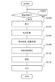
- FIG. 5 is a flowchart of the personal authentication process according to the embodiment.
- the electronic device 1 determines whether or not to start personal authentication (S100). If it is not the time to start personal authentication (S100: NO), the standby state is continued.
- the authentication may be started by using the sensing information of the touch panel 6, for example, as shown by the dotted line in FIG. For example, after the sensed information on the touch panel 6 reaches the range of the camera module 3, the process may shift to the fingerprint information acquisition process.
- the electronic device 1 may be notified that the authentication process will be executed on the website or the like for authentication, and the electronic device 1 may be in the standby state.
- the imaging unit 8 starts receiving light for personal authentication (S102). For example, by activating the camera module 3 for fingerprint authentication, it shifts to a standby state for acquiring fingerprint information and receives light at a required timing. For example, the light received by the photoelectric conversion unit 8a is charged by photoelectric conversion and output as an analog signal at a predetermined timing.
- the analog signal output by the photoelectric conversion unit 8a is converted into a digital signal.
- the information processing unit 10 executes signal processing and image processing other than A / D conversion of the converted digital signal (S106).
- This process is, for example, a clamp, a color-coded output, a defect correction, a color reproduction process, and a storage process in the frame memory 105, as described above.
- the above is given as an example, and in addition to these, more appropriate processing may be executed.
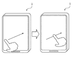
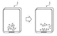
- FIG. 6 shows an example in which the user swipes in a certain direction while touching the display unit 2.
- the user executes the swipe operation in any direction as shown in the left figure to the right figure.
- FIG. 7 shows a fingerprint image taken at a certain timing acquired in this operation.
- the pixels are read from the imaging unit 8 to the information processing unit 10 from the bottom to the top of the drawing.
- the image on the left shows the fingerprint information stored in the frame memory 105 in the photographed state. As shown in the left figure, at this timing, there is image bleeding due to the shutter speed and global shutter distortion.
- the speed detection unit 108 acquires information on the speed and direction of the user's finger movement at the timing from the touch panel 6. For this acquisition, for example, the center of gravity of the sensed information of the touch panel 6 may be obtained, and the acquisition may be performed based on the position of the center of gravity with the frame before and after the timing.
- the correction amount calculation unit 109 calculates the correction amount based on the detected speed. For example, based on the shutter speed and the speed value, it is calculated how much the finger itself deviates at the timing when the image shown in the left figure is acquired.
- the correction unit 110 estimates, for example, the PSF (Point Spread Function) of the motion blur with respect to this correction amount, and acquires a sharpened image by a convolution filter process with.
- the process may be simply sharpened by a morphology treatment, a Laplacian treatment, a Laplacian Gaussian treatment, or the like.
- the matrix parameters may be determined based on the correction amount calculated by the correction amount calculation unit 109.
- the correction unit 110 executes a rolling shutter distortion removal process as the second stage of correction.
- the correction unit 110 removes the rolling shutter distortion based on the correction amount calculated by the correction amount calculation unit 109 and the signal extraction timing of each line in the imaging unit 8. Then, as shown in the right figure, the correction unit 110 acquires the correction fingerprint information that has been sharpened and the rolling shutter distortion has been removed.
- the correction unit 110 stores this correction fingerprint information in the frame memory 105.
- the authentication unit 106 executes authentication using the image including the acquired fingerprint information (S110).
- the authentication may be performed by extracting feature points and performing comparison processing, or by using a trained neural network.
- the electronic device 1 may include a chip capable of executing the above-mentioned information processing and neural network processing on the same substrate as the camera module 3.
- the output unit 107 outputs the authentication result to the required location (S112). For example, in the case of personal authentication when shopping on the web, the personal authentication result may be notified to the browser that opens the website or the application that accepts the authentication result. In this way, the output unit 107 can execute the output at the required location.
- the output unit 107 may notify, for example, that the authentication has failed in order to perform the authentication operation again when the authentication cannot be performed. Further, the output unit 107 may instruct the image pickup unit 8 to take an image again.
- the authentication unit 106 may execute the authentication process using a plurality of fingerprint information. For example, if one of the plurality of fingerprint information can be authenticated, the output unit 107 may be notified at that timing that the authentication is successful.
- the authentication unit 106 may change the threshold value of authentication success or failure based on the authentication accuracy. For example, when high authentication accuracy is required, the authentication accuracy can be improved by increasing the authentication threshold value, for example, the fingerprint matching degree threshold value. To improve the authentication accuracy, for example, the threshold value of the matching degree of the feature points may be raised. Further, when using a neural network model, the threshold value of the degree of agreement may be increased.
- the case where authentication with high accuracy is required is, for example, when trying to purchase an expensive product, when trying to access highly sensitive information, and the like.
- the imaging unit 8 when the imaging unit 8 has a near-infrared filter, a plasmon filter, or the like, it may be authenticated whether or not it is a living body in addition to personal authentication. In this authentication, for example, based on information acquired by near infrared rays or the like, it is authenticated whether or not the wavelength of light is transmitted through hemoglobin such as a vein. When executing this authentication, light such as infrared rays may be emitted from the display unit 2, and this reflected state may be acquired for determination.
- the display panel 4 may emit various colors and authenticate that it is a living body based on the reflection of the emitted light.
- a filter for acquiring various colors may be provided as described above, or so-called multispectral or hyperspectral information may be acquired and analyzed. For example, it is possible to make a judgment based on the skin peculiar to a living body, particularly a human being, or information indicating reflection from the inside of the skin.
- the authentication unit 106 may determine whether or not the sensing region has elasticity on the touch panel 6 and authenticate that it is a living body.
- the imaging unit 8 may be used, and it may be determined whether or not the finger image acquired by the imaging unit 8 has elasticity in terms of time. The elasticity may be determined, for example, based on a change in the shape or size of the area occupied by the finger.
- the touch panel 6 may be provided with a pressure-sensitive sensor, and the elasticity may be determined based on the sensing information of the pressure-sensitive sensor.
- the authentication accuracy may be improved by acquiring fingerprint information at a plurality of timings.
- the imaging unit 8 may acquire fingerprint information at a plurality of timings, and the fingerprint information may be stored in the frame memory 105. Then, authentication may be executed using the accumulated fingerprint information. For example, by referring to the fingerprint information, defects of the image generated at the time of image acquisition may be corrected. More simply, after adjusting the position and angle of the fingerprint, the weighted average of the fingerprint information acquired for each time may be obtained. Then, the fingerprint information acquired by this averaging calculation may be the target of authentication.
- the imaging unit 8 may include a filter other than this. For example, by equipping the light receiving pixel with a polarizing filter, polarized fingerprint information can be acquired. By acquiring the polarized information, it becomes possible to acquire the unevenness of the fingerprint more clearly.
- the information processing unit 10 may synthesize such polarized information to extract feature points.
- the information processing unit 10 may include an image correction unit that corrects deterioration of the image provided in the frame memory 105.
- the present embodiment it is possible to realize highly accurate personal authentication by using the camera module under the display. Furthermore, spoofing can be prevented by authenticating that the person is a human body. Further, in the image pickup unit 8, since the image can be acquired by the operation of the rolling shutter, robust fingerprint authentication against the rolling shutter distortion of the image can be realized.
- the corrected fingerprint information by the correction unit 110 not only the information of one frame but also the information of a plurality of frames may be corrected together.
- the position of the center of gravity may be aligned in the fingerprint information of the plurality of frames.
- some feature points may be extracted and superposed based on these feature points. By superimposing in this way, the features can be acquired more clearly, and the accuracy of fingerprint authentication can be improved.
- the swipe speed of the user was not considered.
- the speed of the user's finger is determined, and further correction of fingerprint information is performed based on the speed.
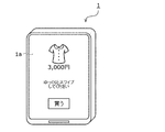
- the speed detection unit 108 When the speed of the finger is faster than the predetermined speed, the speed detection unit 108 outputs to the display unit 2 to urge the user to slow down the swipe speed, for example, as shown in FIG. May be good. Further, as another example, the speed detection unit 108 may notify the output unit 107 that the speed is too high and output the speed to the display unit 2 via the output unit 107. In this case, the output unit 107 is not limited to displaying on the display unit 2, and may, for example, notify the user by sound from the speaker or vibrate the vibrator.
- the output unit 107 may determine the speed based on the desired authentication accuracy. In such a case, for example, when high authentication accuracy is required, the output unit 107 lowers the threshold value for the speed detected by the speed detection unit 108, and the user swipes slowly in a slower speed state. Can be output to.
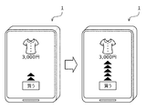
- FIG. 9 shows another example of output.
- the output unit 107 may display that the number of triangular marks displayed within a predetermined time gradually increases, for example, from the figure on the left to the figure on the right.
- the speed at which the triangular marks increase may be the speed at which the imaging unit 8 acquires highly accurate fingerprint information.
- the output unit 107 may output an index (speed guide) indicating speed to the display. This index is not limited to the triangle as shown in FIG. 9, and may be, for example, a diagram in which an arrow extends. There may be.
- the speed detection unit 108 detects the speed based on the detection information of the touch panel 6, but the speed is not limited to this.
- the speed may be detected based on the imaging information acquired by the imaging unit 8.
- the speed detection unit 108 refers to the frame memory 105, and based on the timing from the timing when the image of the user's finger is acquired to the timing when the image of the user's finger cannot be acquired, the time taken between these timings , The speed of the user's finger may be detected based on the size of the fingerprint acquisition area.
- the speed is not limited to this, and the speed may be detected by estimating how much the finger is moving one frame or a plurality of frames after a certain time.
- the present embodiment it is possible to improve the accuracy of fingerprint acquisition or the accuracy of authentication of the acquired fingerprint by detecting the swipe speed of the user's finger. It is also possible to output a prompt to the user so that the speed is suitable for fingerprint acquisition, if necessary.
- the speed detected by the speed detection unit 108 can be used for other purposes.
- the camera module 3 may acquire fingerprint information at an appropriate exposure time based on this speed information.
- the camera module 3 may have a short exposure time when the speed is slow, and a long exposure time as the speed is high.
- authentication is realized with one finger.
- index finger authentication may be used.
- authentication using a plurality of fingers may be performed.
- the imaging unit 8 may acquire not only the information of the index finger but also the information of the middle finger at the same swipe timing, and execute personal authentication based on the two fingers. Further, 3 to 5 fingers may be used, or authentication may be performed with distant fingers such as the index finger and the ring finger. Of course, the combination of these plurality of fingers does not have to include the index finger.
- the timing is the same in the above, different timings, for example, the first authentication may be executed with the index finger and then the second authentication may be executed with the middle finger. In this case, the information of both the right hand and the left hand may be used.
- the information obtained by swiping multiple fingers may be acquired as one authentication information instead of performing authentication for each finger.
- authentication using any number and combination of fingers may be executed at any timing. By increasing the authentication information in this way, it is possible to prevent false detection and spoofing with higher accuracy.
- Multiple finger authentication may be modified based on the required high accuracy of authentication. For example, when high authentication accuracy is required, a plurality of fingers may be used, or a specific combination of fingers may be used.
- the electronic device 1 in each of the above-described embodiments is, for example, a device such as a smartphone.
- a finger may pass over the camera module 3 at a timing other than the fingerprint authentication timing.
- the electronic device 1 acquires such finger information at an arbitrary timing by the imaging unit 8. Then, when the authentication unit 106 can authenticate with the registered user, the photographed fingerprint information may be stored in the storage unit 11. However, even in the case of authentication, if the authentication is successful, the acquired fingerprint information may be stored in the storage unit 11.
- the information processing unit 10 may update the information used for authentication based on the information accumulated at an arbitrary timing. For example, when fingerprint information is acquired as image information, the information stored in the same direction and at the same position is calibrated, and the weighted average is calculated so that the newer the information, the heavier the weighting, and the authentication is performed. It may be used as information.
- this finger may be acquired as information of the other finger of the user at the timing when the user uses the other finger and stored in the storage unit 11. good. By taking such measures, it is possible to improve the authentication accuracy even in the case of the above-mentioned plurality of fingers.
- the information used for authentication can be updated.
- updating it becomes possible to acquire information used for authentication, which is applied to subtle changes in fingers (fingerprints) due to aging, changes due to the environment, and the like. As a result, the accuracy of personal authentication can be maintained high.
- FIGS. 10 and 11 are diagrams schematically showing the electronic device 1 according to the present embodiment.
- the camera module 3 is arranged so as to be longer in the direction perpendicular to the swipe direction.
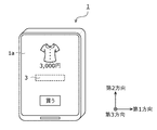
- FIG. 10 when swiping from top to bottom or from bottom to top (second direction), a camera module having a wide area of the imaging unit 8 laterally (first direction).
- FIG. 11 when swiping from left to right or from right to left (first direction), the camera module 3 having a wide area of the imaging unit 8 in the vertical direction (second direction) is used.
- second direction the camera module 3 having a wide area of the imaging unit 8 in the vertical direction
- the imaging unit 8 can be mounted in this way by providing the photoelectric conversion unit 8a (light receiving pixel) in the range shown by the dotted line in FIGS. 10 and 11.
- the size of the light receiving pixels may be, for example, twice or more the number of arrangements on the wider side as the number of arrangements on the narrow side.
- the number of light receiving pixels provided along the first direction may be twice or more the number of light receiving pixels provided along the second direction.
- a guide indicating the swipe direction may be displayed so as to cross a certain range of the light receiving pixels.
- the range in which fingerprint authentication can be performed by swiping that is, the range shown by the dotted line in FIGS. 10 and 11, may be displayed on the display. By displaying in this way, it is also possible to show the user where to swipe to execute personal authentication.
- the swipe area may be made easy for the user to understand by the object displayed on the display unit 2 of the electronic device 1. This object may be dynamically changing.
- FIG. 12 is a diagram showing an example of a GUI (Graphical User Interface) displayed on the display unit 2 of the electronic device 1.
- GUI Graphic User Interface
- the object in the left figure may be trembling or moving within a predetermined area, for example, so as to show the swipe area more clearly.
- the shape and size may be changed by touching the user's finger. It may also disappear so that it fades out after swiping.
- the display of the object is not limited to the polka dots as shown in FIG. 12, and for example, an object having a flow such as a river may be displayed. By displaying such a display, the swipe direction and the like may be indicated to the user. Not limited to these examples, for example, a predetermined character may be displayed, something like a target may be displayed, or a display that is easy for the user to understand may be used.
- the light emitting state of the light emitting element may be changed.
- the wavelength of the reflected light on the display panel 4 touched by the user's finger may be changed, and the change in the wavelength may facilitate the acquisition of fingerprint information.
- the wavelength of the emitted light to a wavelength of yellow to red
- the user's skin color or the reflection from the vein may be easily understood, or conversely, the emission of cyan or the like having a wavelength close to the complementary color may be obtained. By doing so, the wavelength of the reflected light can be made suitable for acquiring fingerprint information.
- the object may change dynamically based on the acquisition status of the fingerprint information. For example, when the fingerprint information is normally acquired, the color of the object may change, the shape may change, or the object may disappear so as to fade out. If the fingerprint information is not acquired normally, the object in the initial state may be displayed, or the color and shape may be changed to those different from those acquired normally. Further, as in the above-described embodiment, the speed guide and the location guide may be displayed.
- the information processing unit 10 may include a fingerprint information acquisition determination unit that determines the acquisition of fingerprint information. The acquisition of fingerprint information may be based on, for example, whether or not a predetermined number or more of irregularities are detected in a predetermined area.
- This may be based on authentication information.
- the object may be changed as described above depending on whether the personal authentication is successful or the personal authentication is unsuccessful.
- two steps may be changed based on the fingerprint information acquisition status and the authentication success / failure status.
- the present embodiment it is possible to widen the area where the image pickup unit 8 exists in the camera module 3 in the direction intersecting the swipe direction.
- the optical fingerprint sensor By providing the optical fingerprint sensor in this way, it is possible to mount the optical fingerprint sensor having robustness against the positional deviation.
- the reading direction in the light receiving pixel is set as the control specification based on the moving direction of the finger.
- FIG. 13 is an example of fingerprint information at a certain timing stored in the frame memory 105 in the present embodiment.
- the output signal is compressed in the vertical direction. More specifically, when the finger is moving with a vector having a positive component in the upward direction of the drawing, if the pixel is read from the upper direction to the lower direction, the rolling shutter causes a rolling shutter. An image compressed in the vertical direction is output.
- the reading direction is controlled by using the speed information detected by the speed detection unit 108.
- the speed information detected by the speed detection unit 108 For example, in the velocity information, when the finger is a vector containing a positive component from the bottom to the top of the drawing, the transfer from the light receiving pixel in the imaging unit 8 is performed from the bottom pixel to the top pixel. ..
- fingerprint information can be acquired not as an image compressed in the vertical direction but as an image stretched in the vertical direction.
- the fingerprint information stretched in this way can be corrected by the correction unit 110 based on the speed information, the shutter speed, and the line reading speed. More specifically, the number of first pixels moved by the finger while the shutter is open is estimated from the speed information and the shutter speed. Then, from the shutter speed and the line reading speed, the number of second pixels indicating how much the pixels are displaced by the rolling shutter while the shutter is open is estimated. Assuming that the fingerprint information is stretched by the number of the first pixel and the second pixel, the correction unit 110 can acquire the fingerprint information having an appropriate vertical size by compressing the fingerprint information in the vertical direction. ..
- the corrected fingerprint information is acquired in the same manner as in the explanation of FIG. In FIG. 7, of course, the corrected fingerprint information may be acquired by compressing the fingerprint information in the vertical direction.
- the present embodiment it is possible to control the scanning direction of the light receiving element in the imaging unit 8 based on the moving direction of the finger and acquire better corrected fingerprint information. By using this corrected fingerprint information, the accuracy of personal authentication can be further improved.
- FIG. 15 is a block diagram showing an example of the electronic device 1 according to the present embodiment.
- the electronic device 1 further includes a tilt detection unit 12.
- the tilt detection unit 12 includes, for example, a gyroscope or an acceleration sensor.
- the tilt detection unit 12 detects the tilt of the electronic device 1 at the timing when the fingerprint information is acquired.
- the tilt is, for example, the tilt of the display with respect to gravity (vertical direction) or horizontal direction.
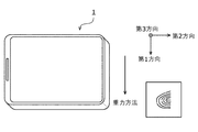
- 16 and 17 are diagrams showing an example of the inclination of the electronic device 1.
- the first direction and the second direction in the electronic device 1 are represented as the sum of the components in the gravitational direction and the horizontal direction intersecting the gravitational direction.
- the certification unit 106 is used for matching such that the finger is peeled upward in the drawing shown in the right figure. Perform fingerprint authentication using data preferentially.
- the authentication unit 106 when the absolute value of the gravity direction component in the first direction in the electronic device 1 is larger than the absolute value of the gravity direction component in the second direction, the authentication unit 106 is shown in the right figure. Fingerprint authentication is performed by preferentially using the matching data such that the finger is pointing to the left in the drawing shown.
- fingerprint authentication can be executed by preferentially using the matching data in which the fingerprint is rotated by 90 degrees depending on which of the four sides is below.
- the matching accuracy is improved and the matching speed is improved by selecting the matching data according to the inclination with respect to gravity or preferentially selecting and using the data. It becomes possible to do. As an example, every 180 degrees or every 90 degrees has been described, but the span of angles may be smaller.
- the personal authentication process may be executed by rotating the corrected fingerprint information based on the result of the tilt detection.
- FIG. 18 is a diagram showing an example of acquisition of fingerprint information according to the present embodiment.
- T0 to t4 shown on the right side of the figure represent the time, and the time changes as t0 ⁇ t1 ⁇ t2 ⁇ t3 ⁇ t4. That is, in FIG. 18, the time changes from the upper figure to the lower figure.
- the imaging unit 8 does not output the signal.
- the imaging unit 8 may determine the transfer of the signal to the information processing unit 10 based on the cumulative value of the signals acquired in the imaging unit 8. In this way, the amount of data included in the fingerprint information may be estimated in the imaging unit 8 to determine the transfer. This estimation of the amount of data may be performed by image analysis.
- the sufficient range may be a preset range, for example, a range determined based on the authentication accuracy of the fingerprint.
- the analog signal is transferred from the imaging unit 8 to the information processing unit 10.
- the fingerprint information from the imaging unit 8 may be transferred when the fingerprint information has a data amount equal to or larger than a predetermined value, and may not be transferred in other cases.
- the sensor may have a high frame rate to avoid the effects of the rolling shutter.
- the frame rate of the image pickup unit 8 is set to about 100 FPS or more.
- the frame rate of the imaging unit 8 may be limited by the transfer rate due to physical mounting such as a bus, the transfer rate due to processing by the information processing unit 10, or the like. In such a case, it may be difficult to transfer all the data to the storage unit 11 or the frame memory 105. Further, when the information is acquired at a frame rate higher than this transfer rate, there is no guarantee that all the information can be appropriately transferred to the information processing unit 10.
- the frame rate of the imaging unit 8 is set to a high frame rate in this way, it is determined that the fingerprint information is acquired in a sufficient range as described above, and then the information processing unit is processed from the imaging unit 8. You may perform the transfer of information to 10.
- the imaging unit 8 acquires an image at a high frame rate to prevent rolling shutter distortion, is it possible to acquire fingerprint information in a range sufficient to be used for authentication? Appropriate authentication accuracy can be ensured by determining whether or not to use the signal and transferring the signal based on the determination result.
- This sufficient range may be defined based on information such as a predetermined area and area, or may be adaptively changed by the information processing unit 10 based on the past authentication result. You may.
- the determination of information acquisition may be included in the concept of "correction" in a broad sense. That is, it is a concept that can be substituted for the correction of each of the above-described embodiments in the sense that the timing of acquiring the fingerprint information is corrected in the time axis direction with respect to the acquisition of the fingerprint information at a predetermined time or between a predetermined plurality of frames.
- the display includes a display surface having light emitting pixels in an array in a first direction and a second direction intersecting the first direction.
- the optical fingerprint sensor has light receiving elements in an array in the first direction and the second direction on the side opposite to the display surface of the display in the third direction intersecting the first direction and the second direction. It is equipped with an image sensor and acquires fingerprint information that moves in contact with the display.
- the information processing unit acquires the corrected corrected fingerprint information from the fingerprint information acquired by the optical fingerprint sensor. Electronics.
- the information processing unit corrects the fingerprint information acquired during an operation including at least a finger swipe operation.
- a touch panel that senses contact information on the display, With more The information processing unit estimates the operating speed from the contact information and acquires the corrected fingerprint information based on the operating speed.
- the electronic device according to (2) The electronic device according to (2).
- the information processing unit selects one fingerprint information from the fingerprint information of a plurality of frames, and aggregates the fingerprint information of another frame into the selected fingerprint information.
- the information processing unit determines the exposure time of the optical fingerprint sensor based on the estimated operating speed.
- the electronic device according to (3) or (4).
- the information processing unit determines the reading direction of the image sensor in the optical fingerprint sensor based on the estimated direction of the operating speed.
- the electronic device according to any one of (2) to (5).
- the instruction displays a speed guide on the display.
- the output of being too fast is at least one of the output to the display, the output by sound, or the output by vibration.
- the information processing unit shortens the exposure time of the optical fingerprint sensor when the speed is faster than a predetermined speed.
- the light emitting pixel outputs light having a different wavelength on the display surface side of the light receiving element.
- the light receiving element acquires the fingerprint information based on reflected light of different wavelengths.
- the electronic device according to any one of (1) to (12).
- a polarizing filter is provided between the light receiving element and the display surface.
- the light receiving element senses polarized light through the polarizing filter.
- the electronic device according to any one of (1) to (13).
- a filter for acquiring the state of hemoglobin is provided between the light receiving element and the display surface.
- the information processing unit acquires the hemoglobin information and performs biometric authentication.
- the electronic device according to any one of (1) to (14).
- the information processing unit performs biometric authentication based on the information of the temporal shape change of the finger in contact with the display surface.
- the electronic device according to any one of (1) to (15).
- the light receiving element detects movements on a plurality of fingers.
- the electronic device according to any one of (2) to (16).
- the information processing unit executes the fingerprint authentication by using a combination of the plurality of fingers in the movement of the plurality of fingers.
- the information processing unit detects finger information and accumulates the fingerprint information while the authentication is being executed or during the time when the authentication is not being executed.
- the electronic device according to any one of (1) to (19).
- the information processing unit accumulates changes in the finger to improve authentication accuracy.
- the information processing unit acquires and accumulates the fingerprint information on a finger other than the unregistered finger.
- the light receiving element is provided with a larger number of elements in a direction intersecting the direction of the swipe operation than the number of elements in the direction of the swipe operation.
- the light receiving element is provided with a number of elements in a direction intersecting the direction of the swipe operation, which is more than twice the number of elements in the direction of the swipe operation.
- a guide for executing the swipe operation is displayed on the display in a direction intersecting with a direction in which many light receiving elements are provided.
- a dynamic object is displayed on the display so as to include an area in which the light receiving element is provided.
- the electronic device according to any one of (1) to (26).
- the light emitting state changes so as to be suitable for acquiring the fingerprint information.
- the electronic device The electronic device.
- the object After the user's finger passes through the object, the object dynamically changes based on the fingerprint information acquisition status or the personal authentication status.
- the electronic device according to any one of (27) to (30).
- a tilt detection unit for detecting the tilt of the display from the horizontal direction is further provided. Authentication of the fingerprint information is executed based on the inclination detected by the inclination detection unit.
- the electronic device according to any one of (1) to (31).
- the optical fingerprint sensor acquires the fingerprint information at a frame rate higher than the transfer rate to the information processing unit, and when the fingerprint information has an information amount equal to or more than a predetermined information amount, the fingerprint information is processed. Transfer to the department, The electronic device according to any one of (1) to (32).
- the imaging speed of the optical fingerprint sensor is a frame rate of 100 FPS (Frame per Second) or higher. (33) The electronic device.
- the optical fingerprint sensor estimates the amount of data contained in the fingerprint information, and when the amount of data exceeds a predetermined value, the fingerprint information is transferred to the information processing unit. (33) or the electronic device according to (34).
- the optical fingerprint sensor estimates the amount of data by image analysis.
- the electronic device according to (35).
- the optical fingerprint sensor estimates the amount of data based on the information on the touch panel.
Landscapes
- Engineering & Computer Science (AREA)
- Theoretical Computer Science (AREA)
- Physics & Mathematics (AREA)
- General Physics & Mathematics (AREA)
- Human Computer Interaction (AREA)
- Business, Economics & Management (AREA)
- Multimedia (AREA)
- Finance (AREA)
- Accounting & Taxation (AREA)
- Computer Security & Cryptography (AREA)
- Life Sciences & Earth Sciences (AREA)
- Health & Medical Sciences (AREA)
- General Engineering & Computer Science (AREA)
- Strategic Management (AREA)
- Biophysics (AREA)
- General Business, Economics & Management (AREA)
- Computer Hardware Design (AREA)
- Software Systems (AREA)
- General Health & Medical Sciences (AREA)
- Marketing (AREA)
- Economics (AREA)
- Development Economics (AREA)
- Heart & Thoracic Surgery (AREA)
- Cardiology (AREA)
- Physiology (AREA)
- Pathology (AREA)
- Veterinary Medicine (AREA)
- Biomedical Technology (AREA)
- Public Health (AREA)
- Surgery (AREA)
- Molecular Biology (AREA)
- Medical Informatics (AREA)
- Animal Behavior & Ethology (AREA)
- Image Input (AREA)
- Collating Specific Patterns (AREA)
- Transforming Light Signals Into Electric Signals (AREA)
- Studio Devices (AREA)
- User Interface Of Digital Computer (AREA)
- Measurement Of The Respiration, Hearing Ability, Form, And Blood Characteristics Of Living Organisms (AREA)
Abstract
[課題]ディスプレイのスワイプ動作中に指紋認証を実現する。 [解決手段]電子機器は、ディスプレイと、光学指紋センサと、情報処理部と、を備える。前記ディスプレイは、第1方向及び前記第1方向に交わる第2方向においてアレイ状に発光画素を有する表示面を備える。前記光学指紋センサは、前記第1方向及び前記第2方向に交わる第3方向において、前記ディスプレイの前記表示面とは逆側に前記第1方向及び前記第2方向においてアレイ状に受光素子を有する撮像素子を備え、前記ディスプレイに接して移動する指紋情報を取得する。前記情報処理部は、前記光学指紋センサが取得した前記指紋情報から、補正された補正指紋情報を取得する。
Description
本開示は、電子機器に関する。
光学式指紋センサは、指紋の取得時において指を所定時間静止させる必要があり、UIの面から利便性が低かった。また、指紋認証によりログインした端末においては、その後の操作は、指紋認証等をしない状態で可能であることが多い。例えば、一度指紋による個人認証を行った後に、ブラウザからクレジットカード決済による買い物が可能であることが多く、セキュリティの問題もある。
本開示の一態様は、ディスプレイのスワイプ動作中に指紋認証を実現する電子機器を提供する。
一実施形態によれば、電子機器は、ディスプレイと、光学指紋センサと、情報処理部と、を備える。前記ディスプレイは、第1方向及び前記第1方向に交わる第2方向においてアレイ状に発光画素を有する表示面を備える。前記光学指紋センサは、前記第1方向及び前記第2方向に交わる第3方向において、前記ディスプレイの前記表示面とは逆側に前記第1方向及び前記第2方向においてアレイ状に受光素子を有する撮像素子を備え、前記ディスプレイに接して移動する指紋情報を取得する。前記情報処理部は、前記光学指紋センサが取得した前記指紋情報から、補正された補正指紋情報を取得する。
前記情報処理部は、少なくとも指のスワイプ動作を含む動作中に取得された前記指紋情報を補正してもよい。
前記ディスプレイに対する接触情報を感知する、タッチパネル、をさらに備え、前記情報処理部は、前記接触情報から動作速度を推定し、前記動作速度に基づいて、前記補正指紋情報を取得してもよい。
前記情報処理部は、複数フレームの前記指紋情報において1の前記指紋情報を選択し、選択された前記指紋情報に、他のフレームの前記指紋情報を集約してもよい。
前記情報処理部は、推定した前記動作速度に基づいて、前記光学指紋センサの露光時間を決定してもよい。
前記情報処理部は、推定した前記動作速度の方向に基づいて、前記光学指紋センサにおける前記撮像素子の読み出し方向を決定してもよい。
要求された認証精度に基づいて、前記スワイプ動作のスピードをゆっくりとする指示を出力してもよい。
前記ディスプレイに、前記スワイプ動作の前記スピードの指示を出力してもよい。
前記指示は、前記ディスプレイにスピードガイドを表示してもよい。
前記スピードが所定スピードよりも速い場合に、前記スピードが速すぎることを出力してもよい。
前記スピードが速すぎることの出力は、前記ディスプレイへの出力、音での出力、又は、振動での出力のうち少なくとも1つであってもよい。
前記情報処理部は、前記スピードが所定のスピードよりも速い場合に、前記光学指紋センサの露光時間を短くしてもよい。
前記発光画素は、前記受光素子の前記表示面側において異なる波長の光を出力してもよく、前記受光素子は、異なる波長の反射光に基づいて前記指紋情報を取得してもよい。
前記受光素子と前記表示面との間に偏光フィルタを備えてもよく、前記受光素子は、前記偏光フィルタを介して偏光された光を感知してもよい。
前記受光素子と前記表示面との間にヘモグロビンの状態を取得するフィルタを備えてもよく、前記情報処理部は、前記ヘモグロビンの情報を取得して生体認証を行ってもよい。
前記情報処理部は、前記表示面に接触した指の時間的な形状変動の情報に基づいて生体認証を行ってもよい。
前記受光素子は、複数の指における動作を検出してもよい。
前記情報処理部は、複数の指の動作において、複数の指の組み合わせを用いて前記指紋認証を実行してもよい。
要求された認証精度に基づいて、複数の指の組み合わせが異なってもよい。
前記情報処理部は、認証を実行する間、又は、認証を実行していない時間において、指の情報を検出し、前記指紋情報を蓄積してもよい。
前記情報処理部は、指の変化を蓄積して認証精度を向上してもよい。
前記情報処理部は、登録されていない指以外の指における前記指紋情報を取得して蓄積してもよい。
前記受光素子は、前記スワイプ動作の方向と交わる方向における素子数が、前記スワイプ動作の方向における素子数よりも多く備えられてもよい。
前記受光素子は、前記スワイプ動作の方向と交わる方向における素子数が、前記スワイプ動作の方向における素子数の2倍よりも多く備えられてもよい。
前記ディスプレイに、前記受光素子が多く備えられる方向と交わる方向に前記スワイプ動作を実行されるガイドを表示してもよい。
前記ディスプレイに、前記受光素子が備えられる領域を表示し、前記領域を通過するように商品情報と、購買ボタンとを配置してもよい。前記商品情報から前記購買ボタンへと前記商品情報を前記スワイプ動作することにより、前記商品の購買を可能とするインタフェース、を備えてもよく、前記指紋認証の結果に基づいて前記購買情報をサーバへと送信してもよい。
前記ディスプレイに、前記受光素子が備えられる領域を含むように動的なオブジェクトを表示してもよい。
前記オブジェクトは、ユーザの指が触れると形状が変化してもよい。
前記オブジェクトは、ユーザの指が触れると発光状態が変化してもよい。
前記発光状態は、前記指紋情報の取得に適するように変化してもよい。
前記オブジェクトは、ユーザの指が通過した後、前記指紋情報の取得状況、又は、個人認証状況に基づいて動的に変化してもよい。
前記ディスプレイの水平方向からの傾きを検出する、傾き検出部、をさらに備えてもよく、前記前記傾き検出部の検出した傾きに基づいて、前記指紋情報の認証を実行してもよい。
前記光学指紋センサは、前記情報処理部への転送レートよりも高いフレームレートで前記指紋情報を取得してもよく、前記指紋情報が所定情報量以上の情報量を有する場合に、前記指紋情報を前記情報処理部へと転送してもよい。
前記光学指紋センサの撮像スピードは、100FPS(Frame per Second)以上のフレームレートであってもよい。
前記光学指紋センサにおいて、前記指紋情報に含まれるデータ量を推定してもよく、前記データ量が所定値を超えている場合に、前記情報処理部へと前記指紋情報を転送してもよい。
前記光学指紋センサは、画像解析により前記データ量を推定してもよい。
前記光学指紋センサは、タッチパネルの情報に基づいて前記データ量を推定してもよい。
以下、図面を参照して、電子機器の実施形態について説明する。以下では、電子機器の主要な構成部分を中心に説明するが、電子機器には、図示又は説明されていない構成部分や機能が存在しうる。以下の説明は、図示又は説明されていない構成部分や機能を除外するものではない。また、説明のためにサイズ、形状、アスペクト比等が変更されているものがあるが、これらは実装においては、適切なサイズ、形状、アスペクト比等を有しているものである。
なお、以下の説明において、取得する信号は、画像情報又は撮像情報として記載しているが、この画像情報、撮像情報とは広義の概念であり、静止画、動画、又は、映像における1フレームの画像等をも含む概念である。また、「より大きい」「より小さい」は、「以上」「以下」とそれぞれ相互に読み替えてもよい。
(第1実施形態)
図1は、一実施形態に係る電子機器を模式的に示す図である。また、図2は、一実施形態に係る電子機器の断面を模式的に示す図である。電子機器1は、例えば、スマートフォン、携帯電話、タブレット型端末、パーソナルコンピュータ等の表示機能と撮影機能とを備える任意のデバイスである。
図1は、一実施形態に係る電子機器を模式的に示す図である。また、図2は、一実施形態に係る電子機器の断面を模式的に示す図である。電子機器1は、例えば、スマートフォン、携帯電話、タブレット型端末、パーソナルコンピュータ等の表示機能と撮影機能とを備える任意のデバイスである。
電子機器1は、表示部2と、カメラモジュール3と、を備える。図1の左図に見られるように、電子機器1の外形サイズの近くまで表示画面1aが拡がっており、表示画面1aの周囲にあるベゼル1bの幅を、例えば、数mm以下にすることも可能である。電子機器1においては、ベゼル1b内において指紋認証部を備えるものが多いが、本実施形態では、点線で示されるように、表示画面1a内にカメラモジュール3を備える。左図に示すように、指紋認証を行うための撮影を行うカメラモジュール3を表示画面1aの裏面側に備えることにより、ベゼル1bの幅を狭めることができる。
なお、図1においては、表示画面1aのほぼ中央あたりの裏面側にカメラモジュール3を配置しているが、表示画面1aの裏面であれば、位置はこの図に限定されるものではない。例えば、表示画面1aの周縁部の近くにカメラモジュール3を配置しても良いし、右図よりも中央より下方に配置されても良い。また、図においては1箇所に配置されているが、配置箇所は1箇所では無く、複数箇所であってもよい。また、この図においては、電子機器1の一方の面に表示部2及びカメラモジュール3を備えるものとしたが、これには限られない。例えば、電子機器1の両面に表示部2及びカメラモジュール3を備えていてもよい。
表示部2は、表示光学系として、表示パネル4、円偏光板5、タッチパネル6及びカバーガラス7を積層した構造体である。なお、これらの並び方は限定されるものではなく、適切に入れ替えたり、また、同じ構成が2以上存在したり、さらに別の構成が含まれるものであったりしてもよい。
表示パネル4は、例えば、OLED(Organic Light Emitting Diode)、液晶、MicroLED、その他の表示原理に基づく発光素子をアレイ状に備えていてもよい。例えば、発光素子は、第1方向及び第2方向を含む平面内にアレイ状に備えられる。OLED等の表示パネル4は、複数の層で構成される。表示パネル4には、カラーフィルタ層等の透過率が低い部材が配置されていることが多い。後述するように、表示パネル4における透過率が低い部材には、カメラモジュール3の配置場所に合わせて貫通孔を形成してもよい。貫通孔を通った被写体光がカメラモジュール3に入射されるようにすれば、カメラモジュール3で撮像される画像の画質を向上することが可能である。
円偏光板5は、ギラツキを低減し、又は、明るい環境下においても表示画面1aの視認性を高める等のために設けられている。タッチパネル6には、タッチセンサが組み込まれている。タッチセンサは、静電容量型、抵抗膜型、感圧型等種々の方式があるが、いずれの方式を用いてもよい。また、タッチパネル6と表示パネル4を一体化しても良い。カバーガラス7は、表示パネル4等を保護するために備えられている。これらの各要素は、光学的に影響の少ない接着剤により接着されていてもよい。
カメラモジュール3は、撮像部8と、光学系9と、を備える。光学系9は、撮像部8の光の入射面側、すなわち、表示部2に近い側に配置され、表示部2を通過した光を撮像部8に集光させる。光学系9は、1又は複数のレンズを備えていてもよい。例えば、この撮像部8は、光学指紋センサとして動作してユーザの指紋情報を取得する。
光学指紋センサとして動作する撮像部8は、複数の光電変換部を備える。それぞれの光電変換部には、レンズが配置される。このレンズは、光学系9により適切に撮像部8へと射出された光をそれぞれの画素を構成する光電変換部において受光させる。光電変換部は、表示部2を介して入射された光を光電変換する。光電変換部は、CMOS(Complementary Metal-Oxide-Semiconductor Field-Effect Transistor)センサでも良いし、CCD(Charge Coupled Device)センサでもよい。光電変換部は、例えば、第1方向及び第2方向が含まれる平面において、アレイ状に備えられる。さらには、光電変換部は、第1方向及び第2方向に沿ってアレイ状に備えられてもよい。例えば、光電変換部の受光素子は、表示部の発光画素と同じ向きに沿ったアレイ状の受光画素として備えられる。
また、光電変換部は、フォトダイオードを備えていてもよいし、有機光電変換膜を備えていてもよい。複数の光電変換部は、任意の方式で配列することができる。複数の光電変換部の配列方法は、例えば、ベイヤ配列であってもよいし、インタライン配列であってもよいし、市松配列であってもよいし、ストライプ配列であってもよいし、その他の配列であってもよい。
本開示においては、光電変換部の出力値、又は、この出力値に基づいて所定の変換をされた値を受光画素値と呼ぶ。
本実施形態では、ディスプレイのカメラモジュール3が存在する領域を指が通過するタイミングにおいて、ユーザの指紋情報を取得し、この指紋情報を用いて個人認証を実行する。例えば、図1の左図にあるように、商品情報と、購買ボタンとがディスプレイに表示されている場合に、商品の画像を購買ボタンにドラッグするタイミングにおいて、カメラモジュール3がスワイプ、フリック、ワイプ等されている指から指紋情報を取得する。この取得は、後述するように、ローリングシャッタを用いて実行される。また、カメラモジュール3は、適切な露光時間において、このローリングシャッタの動作を実行する。
図3は、本実施形態に係る電子機器1のブロック図の一例を示す図である。図1、図2に記載の表示部2の内部については、省略している。電子機器1は、上記で説明したカメラモジュール3と、タッチパネル6と、から情報を出力し、この情報処理を実行する、情報処理部10と、記憶部11と、を備える。
カメラモジュール3の撮像部8は、光電変換部8a(光電変換素子)を備える。光電変換部8aが感知した情報は、例えば、それぞれのラインごとのタイミングで、情報処理部10へと転送される。
情報処理部10は、例えば、CPU(Central Processing Unit)、又は、ASIC(Application Specific Integrated Circuit)、FPGA(Field Programmable Gate Array)等を備えて構成される。この情報処理部10は、以下に説明するように、種々の動作の一部又は全部を行うブロックに分割されていても良いし、各動作の一部又は全部をソフトウェアによる情報処理がCPUにより具体的に実現されるものであってもよい。
記憶部11は、例えば、種々のメモリ、ストレージ等を備える。この記憶部11には、例えば、電子機器1が動作するのに必要となるプログラム、データ等の情報が非一時的に格納されていてもよい。また、メモリは、キャッシュ領域といった一時的な記憶領域を備えていてもよい。
情報処理部10は、A/D変換部100と、クランプ部101と、色別出力部102と、欠陥補正部103と、リニアマトリックス部104と、フレームメモリ105と、認証部106と、出力部107と、速度検出部108と、補正量計算部109と、補正部110と、を備える。フレームメモリ105は、情報処理部10ではなく、記憶部11の一部として備えられてもよい。
A/D変換部100は、光電変換部8aが受光して蓄えられた電荷に基づくアナログ信号を画素ごとにデジタル信号へと変換する。A/D変換部100は、変換したデジタル信号を画像データとして出力する。
クランプ部101は、例えば、黒レベルを規定し、この規定した黒レベルをA/D変換部100から出力された画像データから減算して出力する。クランプ部101は、画素に備えられる光電変換素子ごとにグラウンドレベルを設定しても良く、この場合、取得された光電変換素子ごとに設定されたグラウンドレベルに基づいて、信号値のグラウンド補正を実行する。
色別出力部102は、例えば、光電変換部8aにおいて色別にアナログ信号を取得している場合に、サブピクセル画像のデータを色ごとに出力する。光電変換部8aには、例えば、R(赤)、G(緑)、B(青)の色フィルタ等が備えられている。これらのフィルタ等によりそれぞれの光電変換部8aは、色ごとの感知情報の出力を行う。光電変換部8aにおいて色フィルタが備えられるのではなく、光電変換部8aが有機光電変換膜により色ごとにアナログ信号を取得しても良い。
クランプ部101により、これらのフィルタに基づいてグラウンドレベルを調節し、色別出力部102が、クランプ部101が出力した信号を色別に出力する。光電変換部8aにおいて取得されたアナログ信号には色情報が付加されていない。このため、色別出力部102は、光電変換部8aにおける受光素子ごとに配置されている色に関するデータを記憶しておき、このデータに基づいて色ごとの出力を行ってもよい。
なお、光電変換部8aは、例えば、近赤外光を受光する素子、プラズモンフィルタ等の複雑なスペクトルを取得する等のフィルタが備えられてもよい。これらの場合、単なる色の情報として表現することは難しいが、色別出力部102は、光の波長で区分できるのであれば、これらの情報を波長情報と紐付けて処理をしてもよい。このような場合、波長情報が、範囲を有する情報として色別出力部102は、処理をしてもよい。
欠陥補正部103は、画像データにおける欠陥の補正を実行する。画像データの欠陥は、例えば、画素内に備えられる光電変換素子の欠陥による画素欠け又は情報欠け、あるいは、光学系9における光の飽和による情報落ち等により発生する。欠陥補正部103は、例えば、周囲の画素の情報、又は、同一の色情報を有する周辺の画素の情報などに基づいて補間することで、欠陥補正処理を実行しても良い。
リニアマトリックス部104は、色情報に対する行列演算を実行することにより、色再現を行う。リニアマトリックス部104は、例えば、複数の波長に関する演算を行うことで、望ましい分光を取得する。本実施形態においては、リニアマトリックス部104は、例えば、肌色の検出に適した出力を実行しても良い。さらに、リニアマトリックス部104は、静脈等の生体認証情報を取得するために、黄色から赤色の波長領域の検出に適した出力となるように演算を実行しても良い。
フレームメモリ105は、上述したように、例えば、記憶部11の一部として備えられてもよい。このフレームメモリ105は、光電変換部8aから取得した情報を、上記の処理をした後に一時的に格納する。例えば、情報処理部10は、フレームメモリ105に同じタイミングで取得された指紋情報を、各種上記の処理をし、最終的にリニアマトリックス部104により色再現された一枚の画像データとして保存する。
認証部106は、フレームメモリ105に格納された指紋情報を用いて個人認証を実行する。例えば、この個人認証は、指紋データにおける特徴点を抽出し、抽出された特徴点と、記憶部11に保存されている認証情報とを比較することにより実行される。また、認証部106は、RGB情報だけでは無く、例えば、近赤外線の受光情報、プラズモンフィルタを介して取得された情報に基づいて、なりすまし防止の生体認証を実行しても良い。例えば、フレームメモリ105に格納されているデータにおけるヘモグロビンに対応する波長の情報が正常に取得されているか否かにより、生体認証を実行する。これらは、特徴点等を統計処理により判断しても良いし、別の例として、機械学習により訓練済のニューラルネットワークモデルを用いて認証をしてもよい。
例えば、認証部106は、予め取得しておいた特定のユーザの指紋情報を記憶部11に格納しておく。この格納されたユーザの情報に基づいて、個人認証を実行する。複数のユーザの認証をする場合には、複数ユーザの指紋情報を適切に格納しておく。また、格納された指紋情報は、それぞれの指紋情報の画像、又は、それぞれの指紋情報から取得した特徴点の情報を暗号化しておいても良い。
出力部107は、認証部106による認証結果を出力する。例えば、e-commerce等による買い物であれば、認証結果に基づいて決済処理を行うように、サーバ等に送信してもよい。このように、出力部107は、無線通信を用いて認証結果を送信してもよい。また、別の例として、電子機器1内において、パスワード等による認証の代わりにこの指紋認証等の認証結果を用いてもよい。
速度検出部108は、例えば、タッチパネル6の感知情報に基づいて、カメラモジュール3が指紋の画像を取得するタイミングにおいて、ユーザの指の動きの速さを取得する。すなわち、ユーザがスワイプ動作を行った場合に、カメラモジュール3が受光情報から指紋情報を取得するとともに、タッチパネル6が感知情報から指の速さ情報を取得する。例えば、速度検出部108は、所定時間内におけるタッチパネル6が感知したユーザの指の領域の移動量に基づいて指の速さを取得する。
速度検出部108は、例えば、認証を行うタイミングにおいてユーザの指がタッチスクリーン上に触れた場合に、速度感知のための情報をタッチパネル6から取得する。速度検出部108は、例えば、ユーザの指が動いた場合に、ある時刻におけるタッチパネル6の感知情報と、所定時刻後におけるタッチパネル6の感知情報とを取得する。
タッチパネル6の感知情報は、例えば、指の領域の感知をした場合に、この指の領域の中心点、例えば、重心の位置により取得しても良い。重心の位置は、例えば、感知領域の点の第1方向及び第2方向の加算平均をそれぞれ算出して取得することができる。そして、速度検出部108は、ある時刻と所定時刻後の重心の位置を求めることにより、ユーザの指のスワイプ速度を検出する。
補正量計算部109は、速度検出部108が検出した速度に基づいた補正量を取得する。この補正量に基づいて、フレームメモリ105に格納されている指紋情報に対して画像処理を行ってもよい。この画像処理は、例えば、モーションブラーに基づく画像処理である。指の速度及びシャッタースピードに基づいて、PSFを生成し、指紋情報に逆フィルタ処理(デコンボリューションフィルタ処理)を実行してもよい。
補正部110は、フレームメモリ105に格納されている画像データの補正を実行する。この補正は、補正量計算部109により計算された補正量に基づいて実行される。これらの補正量計算部109による補正量の算出、及び、補正部110による補正については、後述にて詳しく説明する。
図4Aは、図1におけるカメラモジュール3と表示パネル4との関係についてより詳しく説明する図である。カメラモジュール3は、上述したように、例えば、撮像部8と、光学系9と、を備える。光学系9は、撮像部8の光の入射面側、すなわち、表示部2に近い側に配置される。表示部2の表示面を透過した光は、光学系9により撮像部8に伝播される。
撮像部8は、例えば、図3に示すフォトダイオード等の光電変換部8aを備えていてもよい。光学系9により集光、屈折、拡散等され、伝搬された光は、撮像部8に備えられる光電変換部8aにより受光され、アナログ信号と出力する。光電変換部8aは、それぞれの撮像素子の入射面側に、例えば、ベイヤ配列等のカラーフィルタ等が備えられていてもよいし、積層型のカラーフィルタが備えられていてもよい。また、上述したようにカラーフィルタではなく、他のフィルタを備えたり、有機光電変換膜等の他の素子により構成されていたりしてもよい。また、出力に関して、図示しないが、その他受光及びアナログ信号を出力するのに必要となる素子、回路等が備えられる。
光学系9は、例えば、透過率の低い部材における貫通孔を含んだ概念としても良い。貫通孔は、例えば、表示パネル4、特に表示パネル4内における透過率の低い基板aに設けられる開口を含む。光学系9は、例えば、表示パネル4に設けられた開口と、この開口よりも撮像部8に近い位置に配置されるレンズを含む。このレンズと開口により、光学系9は、カメラモジュール3における開口数Na(Numerical Aperture)、F値(F-Number)等の光学的特徴を定義してもよい。
なお、開口とレンズは、一例として示したものであり、光学系9の構成は、必ずしもこれらの組み合わせに限定されるものではない。また、図においては、開口1つに対して1又は複数のレンズが備えられているがこれには限られない。例えば、図4Bに示すように、光学系9において1つのレンズに対して複数の開口が設けられても良い。開口の存在しない領域においては、例えば、表示パネル4の発光素子が備えられ、これらの発光素子の間を縫うように開口が備えられていてもよい。このように配置することにより、表示を崩すこと無く、カメラモジュール3を備えることが可能となる。
撮像部8にアレイ状に配置される受光画素は、例えば、上述した、光電変換部8aを備える。なお、本開示においては、一例として示すものであるので、詳細な説明は省略する。また、本開示における受光画素は、ローリングシャッタとして動作する構成であればよい。
図1から図3についてまとめると、撮像部8は、第3方向において、ディスプレイである表示部2の表示面とは逆側に第1方向及び第2方向においてアレイ状に受光素子を有する撮像素子を備えていてもよい。そして、これらの受光素子のそれぞれは、受光情報を逐次的に読み出すローリングシャッタの動作を実現する。上述したように、情報処理部10は、この撮像部8、すなわち、光学指紋センサが読み出した指紋情報の信号処理を実行する。そして、ユーザは、例えば、表示部2の表示面上において指をすべらせる(例えば、スワイプ動作を行う)ことにより、この光学指紋センサにより指紋情報が取得され、個人認証等を実行することができる。以下においては、スワイプ動作中について説明するが、スワイプには限られず、フリック、ピンチ等、タッチパネル上を滑らせる動きであればよい。
図5は、一実施形態に係る個人認証処理のフローチャートである。
まず、電子機器1は、個人認証を開始するか否かを判断する(S100)。個人認証を開始するタイミングでなければ(S100:NO)、待機状態を続行する。認証の開始は、例えば、図3において点線で示されるように、タッチパネル6の感知情報を用いてもよい。例えば、タッチパネル6における感知情報が、カメラモジュール3の範囲内に到達した後に指紋情報の取得処理に移行しても良い。この前段階として、認証をするべくウェブサイト等において認証処理を実行する旨を電子機器1に通知しておき、電子機器1がスタンバイ状態になっていても良い。
認証開始状態になると(S100:YES)、撮像部8は、個人認証のための受光を開始する(S102)。例えば、カメラモジュール3を指紋認証用に起動することにより、指紋情報の取得の待機状態へと移行し、必要なタイミングで受光を行う。例えば、光電変換部8aが受光した光を光電変換により電荷を蓄え、所定のタイミングにおいてアナログ信号として出力する。
次に、撮像部8により取得されたアナログ信号をA/D変換部 100がA/D変換する(S104)。ここで、光電変換部8aが出力したアナログ信号がデジタル信号へと変換される。
次に、情報処理部10は、変換されたデジタル信号のA/D変換以外の信号処理、画像処理を実行する(S106)。この処理は、例えば、上述したように、クランプ、色別出力、欠陥補正、色再現の処理、そしてフレームメモリ105への格納の処理である。なお、上記は、一例として挙げたものであり、これらに加え、さらに適切な処理が実行されてもよい。
次に、補正部110は、フレームメモリ105に格納されている画像情報の補正を行う(S108)。図6は、ユーザが表示部2上を接触しながらある方向でスワイプする例を示す。ユーザは、左図から右図に示すように、任意の方向にスワイプ動作を実行する。図7は、この動作において取得されたあるタイミングにおいて撮影された指紋画像を示す。なお、本説明においては、例えば、撮像部8から情報処理部10への画素の読み出しが、図面下から上方向に向かって実行されているとする。左が撮影された状態でフレームメモリ105に格納されている指紋情報を示す画像である。この左図に示すように、このタイミングにおいては、シャッタースピードによる像のにじみと、グローバルシャッタ歪みを有する。
まず、S108の処理において、速度検出部108は、タッチパネル6から当該タイミングにおけるユーザの指の動きの速さ及び方向の情報を取得する。この取得は、例えば、タッチパネル6の感知情報の重心を求め、当該タイミングの前後のフレームとの重心の位置により取得しても良い。補正量計算部109は、検出された速度に基づいて、補正量を計算する。例えば、シャッタースピードと速さの値とに基づいて、指自体が、左図の画像を取得したタイミングでどれだけずれたかを算出する。補正部110は、補正の第1段階として、例えば、この補正量に対するモーションブラーのPSF(Point Spread Function)を推定し、でコンボリューションフィルタ処理により、先鋭化された画像を取得する。なお、単純にモルフォロジー処理、ラプラシアン処理、ラプラシアンガウシアン処理等により先鋭化する処理であってもよい。これらの処理の場合も、補正量計算部109が計算した補正量に基づいてマトリックスのパラメータを決定しても良い。
次に、先鋭化された真ん中の画像に対して、補正部110は、補正の第2段階としてローリングシャッタ歪みの除去処理を実行する。補正部110は、補正量計算部109が計算した補正量と、撮像部8における各ラインの信号抽出タイミングとに基づいて、ローリングシャッタ歪みを除去する。そして、右図に示されるように、補正部110は、先鋭化され、かつ、ローリングシャッタ歪みが除去された補正指紋情報を取得する。補正部110は、この補正指紋情報をフレームメモリ105へと格納する。
次に、認証部106は、取得した指紋情報を含む画像を用いて認証を実行する(S110)。認証は、例えば、上述したように、特徴点を抽出して比較処理をしてもよいし、訓練済のニューラルネットワークを用いて実行してもよい。なお、電子機器1は、カメラモジュール3と同じ基板内に、上記の情報処理及びニューラルネットワークの処理を実行できるチップを備えていてもよい。
出力部107は、認証結果を必要な箇所へと出力する(S112)。例えば、ウェブで買い物をする場合の個人認証においては、ウェブサイトを開いているブラウザ、又は、認証結果を受け付けるアプリケーションに個人認証結果を通知しても良い。このように、出力部107は、必要な箇所に出力を実行することができる。
出力部107は、例えば、認証ができなかった場合には、もう一度認証動作を行うべく認証失敗した旨を通知しても良い。また、出力部107から再度、撮像部8に撮像指示をしてもよい。
認証部106は、連続したフレームで画像を取得している場合には、複数の指紋情報を用いて認証処理を実行しても良い。例えば、複数の指紋情報のうち1つにおいて認証できたら、そのタイミングで出力部107に認証が成功した旨の通知をしてもよい。
認証部106は、高い精度での認証が求められる場合、認証精度に基づいて、認証成功、失敗のしきい値を変化させてもよい。例えば、高い認証精度が求められる場合には、認証のしきい値、例えば、指紋の一致度のしきい値を高めることにより、認証精度を高めることができる。認証精度を高めるのは、例えば、特徴点の一致度のしきい値を上げても良い。また、ニューラルネットワークモデルを用いる場合には、一致度のしきい値を上げても良い。高い精度での認証が必要な場合とは、例えば、高価な商品を購入しようとしているとき、機密度の高い情報にアクセスしようとしているとき、等である。
また、撮像部8が近赤外線フィルタ、プラズモンフィルタ等を有する場合には、個人認証とともに、生体であるか否かの認証を行ってもよい。この認証は、例えば、近赤外線等により取得された情報に基づいて、静脈等のヘモグロビンを透過した光の波長であるかを認証する。この認証を実行する場合には、表示部2から、赤外線等の光を発光し、この反射状態を取得して、判定しても良い。
これらには限られず、例えば、表示パネル4が種々の色を発光させ、この発光した光の反射に基づいて、生体であることを認証してもよい。この場合上記のように種々の色を取得するフィルタを備えていてもよく、所謂マルチスペクトル、ハイパースペクトルの情報を取得して解析しても良い。例えば、生体、特に人間に特有の肌、又は、肌の内部からの反射を示すような情報に基づいて判断することが可能である。
生体であることに認証は、撮像部8による取得だけでは無く、例えば、タッチパネル6の感知情報を用いてもよい。例えば、認証部106は、タッチパネル6において感知領域が弾性を有するか否かを判断し、生体であることを認証しても良い。これは、撮像部8を用いても良く、撮像部8において取得された指の画像が時間的にみて弾性を有しているかを判断しても良い。弾性を判断するのは、例えば、指の占める領域の形状の変化や大きさの変化に基づいてもよい。また、タッチパネル6に感圧センサを備えておき、この感圧センサの感知情報に基づいて弾性を判断してもよい。
また、複数のタイミングで指紋情報を取得することにより、認証精度を高めても良い。例えば、撮像部8は、複数のタイミングで指紋情報を取得し、この指紋情報がフレームメモリ105に蓄積されても良い。そして、蓄積された指紋情報を用いて、認証を実行してもよい。例えば、指紋情報同士を参照することにより、画像取得の際に発生した画像の欠陥等を補正してもよい。より単純には、指紋の位置、角度を調節した後、時間ごとに取得された指紋情報の加重平均を求めてもよい。そして、この平均演算により取得された指紋情報を、認証の対象としてもよい。
撮像部8は、これ以外のフィルタを備えていてもよい。例えば、偏光フィルタを受光画素に備えることにより、偏光された指紋情報を取得することができる。偏光した情報を取得することにより、指紋の凹凸をより明確に取得することが可能となる。情報処理部10は、このような偏光された情報を合成して特徴点を抽出してもよい。
また、撮像部8がグローバルフィルタの動作をしていたとしてもシャッタースピードによりモーションブラー等が発生することがある。このモーションブラーに対応するべく、フレームメモリ105に備えられている画像に対して劣化補正をする画像補正部、を情報処理部10は、備えていてもよい。
以上のように、本実施形態によれば、ディスプレイ下にあるカメラモジュールを用いることによる精度の高い個人認証を実現することが可能となる。さらに、人体であることを認証することにより、なりすましの防止をすることもできる。また、撮像部8においては、ローリングシャッタの動作で画像を取得することが可能であるので、画像のローリングシャッタ歪みに対するロバストな指紋認証を実現することができる。
なお、補正部110による補正指紋情報の取得処理においては、1フレームの情報だけでは無く、複数フレームの情報を併せて補正をしてもよい。複数フレームの情報を用いる場合には、例えば、複数フレームの指紋情報において、重心の位置を合わせるようにしてもよい。また、複数フレームに対して図7に示す補正を行った後に、特徴点をいくつか抽出し、これらの特徴点に基づいて重ね合わせても良い。このように重ね合わせることにより、特徴をより鮮明に取得することが可能となり、指紋認証の精度を向上させることができる。
(第2実施形態)
前述の第1実施形態では、ユーザのスワイプ速度については考慮されていなかった。第2実施形態では、ユーザの指の速度を判断し、さらなる当該スピードに基づいた指紋情報の補正を実行する。
前述の第1実施形態では、ユーザのスワイプ速度については考慮されていなかった。第2実施形態では、ユーザの指の速度を判断し、さらなる当該スピードに基づいた指紋情報の補正を実行する。
指の速さが所定速度よりも速かった場合には、速度検出部108は、例えば、図8に示すように、表示部2にスワイプの速度をゆっくりとするようにユーザに促す出力をしてもよい。また、別の例として、速度検出部108は、出力部107へと速度が速過ぎることを通知し、出力部107を介して表示部2へと出力しても良い。なお、この場合、出力部107は、表示部2に表示することに限定されず、例えば、スピーカから音によりユーザに知らせたり、バイブレータを振動させたりしてもよい。
また、出力部107は、望まれる認証精度に基づいてスピードを決定しても良い。このような場合、例えば、高い認証精度が必要な場合には、出力部107は、速度検出部108が検出した速度に対するしきい値を下げ、よりスピードの遅い状態においてゆっくりとスワイプすることをユーザに出力することができる。
図9は、出力の別の例を示すものである。出力部107は、例えば、左の図から、右の図へと至るように、所定時刻内において表示される三角印が徐々に多くなる表示をしても良い。この三角印の増えるスピードが、撮像部8が精度の高い指紋情報を取得するスピードであってもよい。このように、出力部107は、ディスプレイにスピードを示す指標(スピードガイド)を出力しても良い。この指標は、図9のような三角にはかぎられず、例えば、矢印が延びていく図でもよく、これらに限られず、ユーザにスピードを示すようなインタフェースであればどのような図形、形状等であってもよい。
また、速度検出部108は、タッチパネル6の感知情報に基づいてスピードを検出するとしたが、これには限られない。例えば、撮像部8が取得した撮像情報に基づいて、スピードを検出しても良い。速度検出部108は、例えば、フレームメモリ105を参照し、ユーザの指の画像を取得したタイミングから、ユーザの指の画像が取得できなくなるまでのタイミングに基づいて、このタイミング同士に掛かった時間と、指紋取得領域の大きさとに基づいてユーザの指のスピードを検出しても良い。これには限られず、ある時刻から1フレーム又は複数フレーム後にどれだけ指が動いているかを推定してスピードを検出しても良い。
以上のように、本実施形態によれば、ユーザの指のスワイプ速度を検出することにより、指紋取得の精度、又は、取得した指紋の認証の精度を向上させることが可能となる。また、必要に応じて、指紋取得に適したスピードとなるようにユーザに促す出力をすることも可能である。
なお、速度検出部108の検出した速度は、これ以外の用途に用いることもできる。例えば、カメラモジュール3は、この速度情報に基づいて、適切な露光時間で指紋情報を取得しても良い。カメラモジュール3は、例えば、速度が遅い場合には露光時間を短く、速度が速くなるほど露光時間を長くしてもよい。
(第3実施形態)
上述においては、代表例として、指一本により認証を実現する。例えば、人差し指の認証を用いてもよい。さらに、複数の指を用いた認証をしてもよい。
上述においては、代表例として、指一本により認証を実現する。例えば、人差し指の認証を用いてもよい。さらに、複数の指を用いた認証をしてもよい。
例えば、撮像部8は、人差し指だけでは無く、中指の情報も同じスワイプのタイミングで取得し、2本の指に基づいた個人認証を実行しても良い。さらに、3本から5本の指を用いてもよいし、人差し指と薬指といった離れた指で認証を行ってもよい。もちろん、これらの複数の指の組合せに人差し指が含まれなくても良い。
上記では同じタイミングとしているが、異なるタイミング、例えば、人差し指で第1認証を実行した後に、中指で第2認証を実行する、等してもよい。この場合、右手と左手の両手の情報を用いてもよい。
複数本の指を同じタイミングで情報を取得する場合には、1本の指ごとの認証を実行するのでは無く、複数本の指をスワイプした情報を1つの認証情報として取得しても良い。
以上のように、任意のタイミングにおいて任意の本数、組み合わせの指を用いた認証を実行してもよい。このように認証情報を増やすことにより、誤検知やなりすましをさらに精度良く防ぐことが可能となる。複数本の指による認証は、必要とされる認証精度の高さに基づいて変更してもよい。例えば、高い認証精度が必要となる場合に、複数本の指を用いたり、特定の組み合わせの指を用いたりしてもよい。
(第4実施形態)
前述の各実施形態における電子機器1は、例えば、スマートフォン等のデバイスである。このようなタッチパネルを備えるデバイスにおいては、指紋認証のタイミング以外においてもカメラモジュール3上を指が通過することがある。
前述の各実施形態における電子機器1は、例えば、スマートフォン等のデバイスである。このようなタッチパネルを備えるデバイスにおいては、指紋認証のタイミング以外においてもカメラモジュール3上を指が通過することがある。
そこで、本実施形態に係る電子機器1は、撮像部8により、任意のタイミングでこのような指の情報を取得する。そして、認証部106により、登録されているユーザと認証できた場合に、この撮影された指紋情報を、記憶部11に記憶しておいても良い。もっとも、認証を行う場合においても、認証が成功した場合には、取得した指紋情報を記憶部11に記憶してもよい。
そして、情報処理部10は、任意のタイミングで蓄積した情報に基づいて認証に用いる情報を更新しても良い。例えば、指紋情報が画像情報として取得されている場合には、同じ方向及び同じ位置に蓄積された情報をキャリブレーションし、新しい情報ほど重み付けが重くなるように重み付き平均を算出して、認証に用いる情報としてもよい。
また、所定の指において個人認証がされた場合に、ユーザが他の指を用いたタイミングにおいて、この指を当該ユーザの他の指の情報として取得し、記憶部11に格納しておいても良い。このように対応することにより、上述の複数本の指の場合においても認証精度を高めることが可能となる。
以上のように本実施形態によれば、認証に用いる情報を更新することができる。更新することにより、加齢による指(指紋)の微妙な変化や、環境による変化等にも適用する、認証に用いる情報を取得することが可能となる。この結果、個人認証の精度を高く維持することができる。
(第5実施形態)
図10及び図11は、本実施形態に係る電子機器1を模式的に示す図である。本実施形態においては、カメラモジュール3がスワイプ方向に対して垂直方向が長くなるように配置されている。例えば、図10に示すように、上から下、又は、下から上(第2方向)にスワイプを行う場合には、横(第1方向)に広い撮像部8の存在する領域を有するカメラモジュール3を用いる。図11に示すように、左から右、又は、右から左(第1方向)にスワイプを行う場合には、縦(第2方向)に広い撮像部8の存在する領域を有するカメラモジュール3を用いる。
図10及び図11は、本実施形態に係る電子機器1を模式的に示す図である。本実施形態においては、カメラモジュール3がスワイプ方向に対して垂直方向が長くなるように配置されている。例えば、図10に示すように、上から下、又は、下から上(第2方向)にスワイプを行う場合には、横(第1方向)に広い撮像部8の存在する領域を有するカメラモジュール3を用いる。図11に示すように、左から右、又は、右から左(第1方向)にスワイプを行う場合には、縦(第2方向)に広い撮像部8の存在する領域を有するカメラモジュール3を用いる。
例えば、撮像部8は、光電変換部8a(受光画素)を図10、図11に点線で示される範囲で備えておくことにより、このような実装をすることができる。この受光画素の大きさは、例えば、広い方の配置数が狭い方の配置数の2倍以上となるようにしてもよい。例えば、図10においては、第1方向に沿って備えられる受光画素が、第2方向に沿って備えられる受光画素の2倍以上であってもよい。
そして、さらに、受光画素がある範囲を横切るように、図11に示すように、スワイプの方向を示すガイドを表示しても良い。別の例として、スワイプ動作により指紋認証を行える範囲、すなわち、図10、図11において点線で示される範囲を、ディスプレイ上に表示してもよい。このように表示することにより、ユーザにどこをスワイプすることで個人認証を実行できるかを示すことも可能となる。
(第6実施形態)
電子機器1の表示部2に表示されるオブジェクトにより、スワイプ領域をユーザにわかりやすくしても良い。このオブジェクトは、動的に変化するものであってもよい。
電子機器1の表示部2に表示されるオブジェクトにより、スワイプ領域をユーザにわかりやすくしても良い。このオブジェクトは、動的に変化するものであってもよい。
図12は、電子機器1の表示部2に表示されるGUI(Graphical User Interface)の一例を示す図である。表示部2には、例えば、左図に示すように水滴のような円状のオブジェクトが表示されている。そして、この円状のオブジェクトを横切るようにユーザがスワイプをすると、右図に示すように、オブジェクトがばらけるような動作をしてもよい。
また、スワイプ待ちの状態において、スワイプ領域をより明確に示すように、左図のオブジェクトは、例えば、震えていたり、所定領域内を移動していたりしても良い。ユーザの指が触れることにより、その形状、大きさが変化してもよい。また、スワイプ後にフェードアウトするように消えても良い。
オブジェクトの表示は、図12のような水玉に限定されるものではなく、例えば、川のように流れを有するオブジェクトを表示してもよい。このような表示にすることにより、ユーザにスワイプの方向等を示しても良い。これらの例に限られず、例えば、所定のキャラクターを表示したり、的のようなものを表示したり、ユーザにわかりやすい表示をするものであればよい。
このオブジェクト領域に、ユーザの指が触れると、発光素子の発光状態を変化させてもよい。発光状態を変化させることにより、ユーザの指が触れている表示パネル4における反射光の波長を変化させ、この波長の変化により、指紋情報の取得をしやすくしてもよい。例えば、発光する光の波長を黄~赤の波長にすることにより、ユーザの肌の色、又は、静脈からの反射がわかりやすい状況としても良いし、逆に補色に近い波長を有するシアン等の発光をすることにより、反射する光の波長を指紋情報の取得に適したものとすることができる。
そして、オブジェクトは、指紋情報の取得状況に基づいて、動的に変化してもよい。例えば、指紋情報が正常に取得された場合には、オブジェクトの色が変化したり、形状が変化したり、又は、フェードアウトするように消えたりしても良い。指紋情報が正常に取得されない場合には、初期状態のオブジェクトを表示したり、色、形状を正常に取得された場合と異なるものへと変化させたりしてもよい。また、前述した実施形態のように、スピードガイド、場所のガイドを表示してもよい。情報処理部10は、指紋情報の取得を判定する、指紋情報取得判定部を備えていてもよい。指紋情報の取得は、例えば、所定の領域内に、所定数以上の凹凸を感知したか否か等に基づいても良い。
これは、認証情報に基づいていても良い。例えば、個人認証が成功した場合と、個人認証が失敗した場合で、上記のようにオブジェクトを変化させてもよい。もちろん、指紋情報の取得状況、認証の成否状況に基づいて、2段階の変化をさせてもよい。
以上のように本実施形態によれば、カメラモジュール3における撮像部8の存在する領域をスワイプ方向に対して交わる方向に広くすることも可能である。このように光学指紋センサを備えておくことにより、位置ズレに対してロバストネスを有する光学指紋センサを実装することが可能となる。
(第7実施形態)
前述の実施形態までにおいて、指の速度情報に基づいた様々な形態を説明した。本実施形態ではさらに、指の動く方向に基づいて、受光画素における読み取りの方向を制御仕様とするものである。
前述の実施形態までにおいて、指の速度情報に基づいた様々な形態を説明した。本実施形態ではさらに、指の動く方向に基づいて、受光画素における読み取りの方向を制御仕様とするものである。
図13は、本実施形態においてフレームメモリ105に格納されたあるタイミングにおける指紋情報の一例である。例えば、図7と同じ状況において、撮像部8による画素の読み出した下から上方向へと実行された場合、出力される信号は、縦方向に圧縮される。より具体的には、指が図面上方向に正の成分を持つベクトルを有した動きをしている場合に、画素の読み取りを上方向から下方向へと実行してしまうと、ローリングシャッタにより、上下方向に圧縮された画像が出力される。
このような指紋情報であると、補正部110が補正を行うのが困難である場合がある。そこで本実施形態では、速度検出部108が検出した速度情報を用いて、読み出し方向を制御する。例えば、速度情報において、指が図面の下から上へと向かう正の成分を含むベクトルである場合、撮像部8における受光画素からの転送を、下の画素から、上の画素へと向けて行う。このように転送することにより、図14に示すように、上下方向に圧縮された画像ではなく、上下方向に伸張された画像として指紋情報を取得することができる。
このように伸張された指紋情報は、速度情報、シャッタースピード及びラインの読み出し速度に基づいて補正部110が補正を行うことが可能となる。より具体的には、速度情報、シャッタースピードにより、シャッターが開いている間に指が移動した第1画素数を推定する。そして、シャッタースピード及びラインの読み出し速度から、シャッターが開いている間にローリングシャッタによりどれだけ画素がずれるかを示す第2画素数を推定する。補正部110は、これらの第1画素数及び第2画素数だけ指紋情報が伸張されたとして、上下方向に圧縮することにより、適正な上下方向の大きさを有する指紋情報を取得することができる。
この後は、図7の説明と同様に、補正指紋情報を取得する。なお、図7においても、もちろん上下方向の指紋情報の圧縮処理をして、補正指紋情報を取得しても良い。
以上のように、本実施形態によれば、指の動く方向に基づいて、撮像部8における受光素子のスキャン方向を制御し、よりよい補正指紋情報を取得することが可能となる。この補正指紋情報を用いることにより、個人認証精度をさらに向上させることができる。
(第8実施形態)
図15は、本実施形態に係る電子機器1の一例を示すブロック図である。電子機器1は、さらに、傾き検出部12を備える。
図15は、本実施形態に係る電子機器1の一例を示すブロック図である。電子機器1は、さらに、傾き検出部12を備える。
傾き検出部12は、例えば、ジャイロスコープ又は加速度センサを備える。傾き検出部12は、指紋情報を取得したタイミングにおける電子機器1の傾きを検出する。傾きとは、例えば、重力(鉛直方向)又は水平方向に対するディスプレイの傾きである。
図16及び図17は、電子機器1の傾きの一例を示す図である。例えば、図16に示すように、電子機器1における第1方向及び第2方向を、重力方向及びこれに交わる水平方向の成分の和として表す。第1方向の重力方向成分の絶対値が、第2方向の重力方向の成分の絶対値よりも小さい場合、認証部106は、右図に示す図面上向きに指がむいているようなマッチング用のデータを優先的に用いて指紋認証を実行する。
一方で、図17に示すように、電子機器1における第1方向の重力方向成分の絶対値が、第2方向の重力方向の成分の絶対値よりも大きい場合、認証部106は、右図に示す図面左向きに指が向いているようなマッチング用のデータを優先的に用いて指紋認証を実行する。
また、各方向における重力方向の大きさと、符号とを用いてもよい。この場合、例えば、4辺のいずれが下方にあるかで、指紋を90度ずつ回転させたマッチング用データを優先的に用いて指紋認証を実行することができる。
以上のように、本実施形態によれば、マッチング用のデータを重力に対する傾きにより選択し、又は、優先的に選択して用いることにより、マッチングの精度を向上したり、マッチングの速度を向上したりすることが可能となる。一例として、180度ごと、又は、90度ごとについて説明したが、角度のスパンはより小さくても良い。
また、マッチングのパターンを選択するとしたが、これには限られない。例えば、傾き検出の結果に基づいて、補正指紋情報を回転させて個人認証処理を実行してもよい。
(第9実施形態)
図18は、本実施形態に係る指紋情報の取得の一例を示す図である。図の右側に記載されているt0~t4は、時刻を表し、t0 < t1 < t2 < t3 < t4のように時刻が遷移する。すなわち、この図18においては、上図から下図へ向かって時間が遷移する。
図18は、本実施形態に係る指紋情報の取得の一例を示す図である。図の右側に記載されているt0~t4は、時刻を表し、t0 < t1 < t2 < t3 < t4のように時刻が遷移する。すなわち、この図18においては、上図から下図へ向かって時間が遷移する。
時刻t = t0においては、指紋が未検出であるため、撮像部8は、信号の出力を行わない。
時刻t = t1, t2においては、指紋が検出されているものの、認証に用いる十分な範囲の指紋が取得できていないので、撮像部8は、情報処理部10への信号の出力を行わない。例えば、撮像部8は、撮像部8内において取得されている信号の累積値に基づいて、情報処理部10への信号の転送の判断をしてもよい。このように、撮像部8内において、指紋情報に含まれるデータ量を推定し、転送の判断をしてもよい。このデータ量の推定は、画像解析により実行されてもよい。
別の例として、タッチパネル6における指の位置情報又は撮像部8と重なる表示面への指の接触面積等の情報を用いて、転送を行うか否かを判断しても良い。十分な範囲とは、予め設定した範囲でも良く、例えば、指紋における認証精度に基づいて決定される範囲であってもよい。
時刻t = t3, t4においては、指紋が十分な範囲で検出されているので、撮像部8から情報処理部10へのアナログ信号の転送が実行される。この範囲においては、個人認証が十分な精度で実現できる。すなわち、撮像部8からの指紋情報の転送は、当該指紋情報が所定値以上のデータ量である場合には、転送を行い、それ以外の場合には、転送を行わなくてもよい。
ローリングシャッタの影響を回避するべく、センサを高フレームレートにすることがある。例えば、情報処理部10における処理が30FPS(Frame per Second)~60FPS程度で実行されれば十分である状況において、撮像部8のフレームレートを100FPS程度以上にする。撮像部8のフレームレートがバス等の物理実装による転送レート、又は、情報処理部10における処理による転送レート等により制限されることがある。このような場合、記憶部11やフレームメモリ105に全てのデータを転送することが困難である場合がある。また、この転送レートよりも高いフレームレートで情報を取得する場合には、全ての情報を適切に情報処理部10へと転送できる保証はない。
そこで、このように撮像部8のフレームレートを高フレームレートとする場合には、上記のように十分な範囲において指紋情報が取得されていることを判断した上で、撮像部8から情報処理部10への情報の転送を実行してもよい。
以上のように、本実施形態によれば、撮像部8が高いフレームレートで画像を取得してローリングシャッタ歪みを防ぐ場合においても、認証に用いるのに十分な範囲の指紋情報が取得できているか否かを判断して、その判断結果に基づいて信号の転送をすることにより、適切な認証精度を確保することが可能となる。この十分な範囲は、予め決められた領域、面積等の情報に基づいて定義されていてもよいし、又は、過去の認証結果に基づいて、情報処理部10が適応的に変化させるものであってもよい。
なお、前述の各実施形態においては、「補正」として説明したが、本実施形態においては、この情報取得の判断を広い意味での「補正」という概念に含めても良い。すなわち、所定時間又は所定複数フレーム間における指紋情報の取得に対し、時間軸方向に、指紋情報の取得するタイミングを補正する、と意味において、前述した各実施形態の補正に代替できる概念である。
なお、本技術は以下のような構成を取ることができる。
(1)
ディスプレイと、
光学指紋センサと、
情報処理部と、
を備え、
前記ディスプレイは、第1方向及び前記第1方向に交わる第2方向においてアレイ状に発光画素を有する表示面を備え、
前記光学指紋センサは、前記第1方向及び前記第2方向に交わる第3方向において、前記ディスプレイの前記表示面とは逆側に前記第1方向及び前記第2方向においてアレイ状に受光素子を有する撮像素子を備え、前記ディスプレイに接して移動する指紋情報を取得し、
前記情報処理部は、前記光学指紋センサが取得した前記指紋情報から、補正された補正指紋情報を取得する、
電子機器。
ディスプレイと、
光学指紋センサと、
情報処理部と、
を備え、
前記ディスプレイは、第1方向及び前記第1方向に交わる第2方向においてアレイ状に発光画素を有する表示面を備え、
前記光学指紋センサは、前記第1方向及び前記第2方向に交わる第3方向において、前記ディスプレイの前記表示面とは逆側に前記第1方向及び前記第2方向においてアレイ状に受光素子を有する撮像素子を備え、前記ディスプレイに接して移動する指紋情報を取得し、
前記情報処理部は、前記光学指紋センサが取得した前記指紋情報から、補正された補正指紋情報を取得する、
電子機器。
(2)
前記情報処理部は、少なくとも指のスワイプ動作を含む動作中に取得された前記指紋情報を補正する、
(1)に記載の電子機器。
前記情報処理部は、少なくとも指のスワイプ動作を含む動作中に取得された前記指紋情報を補正する、
(1)に記載の電子機器。
(3)
前記ディスプレイに対する接触情報を感知する、タッチパネル、
をさらに備え、
前記情報処理部は、前記接触情報から動作速度を推定し、前記動作速度に基づいて、前記補正指紋情報を取得する、
(2)に記載の電子機器。
前記ディスプレイに対する接触情報を感知する、タッチパネル、
をさらに備え、
前記情報処理部は、前記接触情報から動作速度を推定し、前記動作速度に基づいて、前記補正指紋情報を取得する、
(2)に記載の電子機器。
(4)
前記情報処理部は、複数フレームの前記指紋情報において1の前記指紋情報を選択し、選択された前記指紋情報に、他のフレームの前記指紋情報を集約する、
(3)に記載の電子機器。
前記情報処理部は、複数フレームの前記指紋情報において1の前記指紋情報を選択し、選択された前記指紋情報に、他のフレームの前記指紋情報を集約する、
(3)に記載の電子機器。
(5)
前記情報処理部は、推定した前記動作速度に基づいて、前記光学指紋センサの露光時間を決定する、
(3)又は(4)に記載の電子機器。
前記情報処理部は、推定した前記動作速度に基づいて、前記光学指紋センサの露光時間を決定する、
(3)又は(4)に記載の電子機器。
(6)
前記情報処理部は、推定した前記動作速度の方向に基づいて、前記光学指紋センサにおける前記撮像素子の読み出し方向を決定する、
(2)から(5)のいずれかに記載の電子機器。
前記情報処理部は、推定した前記動作速度の方向に基づいて、前記光学指紋センサにおける前記撮像素子の読み出し方向を決定する、
(2)から(5)のいずれかに記載の電子機器。
(7)
要求された認証精度に基づいて、前記スワイプ動作のスピードをゆっくりとする指示を出力する、
(5)から(6)のいずれかに記載の電子機器。
要求された認証精度に基づいて、前記スワイプ動作のスピードをゆっくりとする指示を出力する、
(5)から(6)のいずれかに記載の電子機器。
(8)
前記ディスプレイに、前記スワイプ動作の前記スピードの指示を出力する、
(7)に記載の電子機器。
前記ディスプレイに、前記スワイプ動作の前記スピードの指示を出力する、
(7)に記載の電子機器。
(9)
前記指示は、前記ディスプレイにスピードガイドを表示する、
(7)又は(8)に記載の電子機器。
前記指示は、前記ディスプレイにスピードガイドを表示する、
(7)又は(8)に記載の電子機器。
(10)
前記スピードが所定スピードよりも速い場合に、前記スピードが速すぎることを出力する、
(7)から(9)のいずれかに記載の電子機器。
前記スピードが所定スピードよりも速い場合に、前記スピードが速すぎることを出力する、
(7)から(9)のいずれかに記載の電子機器。
(11)
前記スピードが速すぎることの出力は、前記ディスプレイへの出力、音での出力、又は、振動での出力のうち少なくとも1つである、
(10)に記載の電子機器。
前記スピードが速すぎることの出力は、前記ディスプレイへの出力、音での出力、又は、振動での出力のうち少なくとも1つである、
(10)に記載の電子機器。
(12)
前記情報処理部は、前記スピードが所定のスピードよりも速い場合に、前記光学指紋センサの露光時間を短くする、
(5)に記載の電子機器。
前記情報処理部は、前記スピードが所定のスピードよりも速い場合に、前記光学指紋センサの露光時間を短くする、
(5)に記載の電子機器。
(13)
前記発光画素は、前記受光素子の前記表示面側において異なる波長の光を出力し、
前記受光素子は、異なる波長の反射光に基づいて前記指紋情報を取得する、
(1)から(12)のいずれかに記載の電子機器。
前記発光画素は、前記受光素子の前記表示面側において異なる波長の光を出力し、
前記受光素子は、異なる波長の反射光に基づいて前記指紋情報を取得する、
(1)から(12)のいずれかに記載の電子機器。
(14)
前記受光素子と前記表示面との間に偏光フィルタを備え、
前記受光素子は、前記偏光フィルタを介して偏光された光を感知する、
(1)から(13)のいずれかに記載の電子機器。
前記受光素子と前記表示面との間に偏光フィルタを備え、
前記受光素子は、前記偏光フィルタを介して偏光された光を感知する、
(1)から(13)のいずれかに記載の電子機器。
(15)
前記受光素子と前記表示面との間にヘモグロビンの状態を取得するフィルタを備え、
前記情報処理部は、前記ヘモグロビンの情報を取得して生体認証を行う、
(1)から(14)のいずれかに記載の電子機器。
前記受光素子と前記表示面との間にヘモグロビンの状態を取得するフィルタを備え、
前記情報処理部は、前記ヘモグロビンの情報を取得して生体認証を行う、
(1)から(14)のいずれかに記載の電子機器。
(16)
前記情報処理部は、前記表示面に接触した指の時間的な形状変動の情報に基づいて生体認証を行う、
(1)から(15)のいずれかに記載の電子機器。
前記情報処理部は、前記表示面に接触した指の時間的な形状変動の情報に基づいて生体認証を行う、
(1)から(15)のいずれかに記載の電子機器。
(17)
前記受光素子は、複数の指における動作を検出する、
(2)から(16)のいずれかに記載の電子機器。
前記受光素子は、複数の指における動作を検出する、
(2)から(16)のいずれかに記載の電子機器。
(18)
前記情報処理部は、複数の指の動作において、複数の指の組み合わせを用いて前記指紋認証を実行する、
(17)に記載の電子機器。
前記情報処理部は、複数の指の動作において、複数の指の組み合わせを用いて前記指紋認証を実行する、
(17)に記載の電子機器。
(19)
要求された認証精度に基づいて、複数の指の組み合わせが異なる、
(18)に記載の電子機器。
要求された認証精度に基づいて、複数の指の組み合わせが異なる、
(18)に記載の電子機器。
(20)
前記情報処理部は、認証を実行する間、又は、認証を実行していない時間において、指の情報を検出し、前記指紋情報を蓄積する、
(1)から(19)のいずれかに記載の電子機器。
前記情報処理部は、認証を実行する間、又は、認証を実行していない時間において、指の情報を検出し、前記指紋情報を蓄積する、
(1)から(19)のいずれかに記載の電子機器。
(21)
前記情報処理部は、指の変化を蓄積して認証精度を向上する、
(20)に記載の電子機器。
前記情報処理部は、指の変化を蓄積して認証精度を向上する、
(20)に記載の電子機器。
(22)
前記情報処理部は、登録されていない指以外の指における前記指紋情報を取得して蓄積する、
(20)又は(21)に記載の電子機器。
前記情報処理部は、登録されていない指以外の指における前記指紋情報を取得して蓄積する、
(20)又は(21)に記載の電子機器。
(23)
前記受光素子は、前記スワイプ動作の方向と交わる方向における素子数が、前記スワイプ動作の方向における素子数よりも多く備えられる、
(2)から(12)のいずれかに記載の電子機器。
前記受光素子は、前記スワイプ動作の方向と交わる方向における素子数が、前記スワイプ動作の方向における素子数よりも多く備えられる、
(2)から(12)のいずれかに記載の電子機器。
(24)
前記受光素子は、前記スワイプ動作の方向と交わる方向における素子数が、前記スワイプ動作の方向における素子数の2倍よりも多く備えられる、
(23)に記載の電子機器。
前記受光素子は、前記スワイプ動作の方向と交わる方向における素子数が、前記スワイプ動作の方向における素子数の2倍よりも多く備えられる、
(23)に記載の電子機器。
(25)
前記ディスプレイに、前記受光素子が多く備えられる方向と交わる方向に前記スワイプ動作を実行されるガイドを表示する、
(23)又は(24)に記載の電子機器。
前記ディスプレイに、前記受光素子が多く備えられる方向と交わる方向に前記スワイプ動作を実行されるガイドを表示する、
(23)又は(24)に記載の電子機器。
(26)
前記ディスプレイに、前記受光素子が備えられる領域を表示し、前記領域を通過するように商品情報と、購買ボタンとを配置し、前記商品情報から前記購買ボタンへと前記商品情報を前記スワイプ動作することにより、前記商品の購買を可能とするインタフェース、
を備え、
前記指紋認証の結果に基づいて前記購買情報をサーバへと送信する、
(2)から(12)のいずれかに記載の電子機器。
前記ディスプレイに、前記受光素子が備えられる領域を表示し、前記領域を通過するように商品情報と、購買ボタンとを配置し、前記商品情報から前記購買ボタンへと前記商品情報を前記スワイプ動作することにより、前記商品の購買を可能とするインタフェース、
を備え、
前記指紋認証の結果に基づいて前記購買情報をサーバへと送信する、
(2)から(12)のいずれかに記載の電子機器。
(27)
前記ディスプレイに、前記受光素子が備えられる領域を含むように動的なオブジェクトを表示する、
(1)から(26)のいずれかに記載の電子機器。
前記ディスプレイに、前記受光素子が備えられる領域を含むように動的なオブジェクトを表示する、
(1)から(26)のいずれかに記載の電子機器。
(28)
前記オブジェクトは、ユーザの指が触れると形状が変化する、
(27)に記載の電子機器。
前記オブジェクトは、ユーザの指が触れると形状が変化する、
(27)に記載の電子機器。
(29)
前記オブジェクトは、ユーザの指が触れると発光状態が変化する、
(27)に記載の電子機器。
前記オブジェクトは、ユーザの指が触れると発光状態が変化する、
(27)に記載の電子機器。
(30)
前記発光状態は、前記指紋情報の取得に適するように変化する、
(29)に記載の電子機器。
前記発光状態は、前記指紋情報の取得に適するように変化する、
(29)に記載の電子機器。
(31)
前記オブジェクトは、ユーザの指が通過した後、前記指紋情報の取得状況、又は、個人認証状況に基づいて動的に変化する、
(27)から(30)のいずれかに記載の電子機器。
前記オブジェクトは、ユーザの指が通過した後、前記指紋情報の取得状況、又は、個人認証状況に基づいて動的に変化する、
(27)から(30)のいずれかに記載の電子機器。
(32)
前記ディスプレイの水平方向からの傾きを検出する、傾き検出部、をさらに備え、
前記前記傾き検出部の検出した傾きに基づいて、前記指紋情報の認証を実行する、
(1)から(31)のいずれかに記載の電子機器。
前記ディスプレイの水平方向からの傾きを検出する、傾き検出部、をさらに備え、
前記前記傾き検出部の検出した傾きに基づいて、前記指紋情報の認証を実行する、
(1)から(31)のいずれかに記載の電子機器。
(33)
前記光学指紋センサは、前記情報処理部への転送レートよりも高いフレームレートで前記指紋情報を取得し、前記指紋情報が所定情報量以上の情報量を有する場合に、前記指紋情報を前記情報処理部へと転送する、
(1)から(32)のいずれかに記載の電子機器。
前記光学指紋センサは、前記情報処理部への転送レートよりも高いフレームレートで前記指紋情報を取得し、前記指紋情報が所定情報量以上の情報量を有する場合に、前記指紋情報を前記情報処理部へと転送する、
(1)から(32)のいずれかに記載の電子機器。
(34)
前記光学指紋センサの撮像スピードは、100FPS(Frame per Second)以上のフレームレートである、
(33)に記載の電子機器。
前記光学指紋センサの撮像スピードは、100FPS(Frame per Second)以上のフレームレートである、
(33)に記載の電子機器。
(35)
前記光学指紋センサにおいて、前記指紋情報に含まれるデータ量を推定し、前記データ量が所定値を超えている場合に、前記情報処理部へと前記指紋情報を転送する、
(33)又は(34)に記載の電子機器。
前記光学指紋センサにおいて、前記指紋情報に含まれるデータ量を推定し、前記データ量が所定値を超えている場合に、前記情報処理部へと前記指紋情報を転送する、
(33)又は(34)に記載の電子機器。
(36)
前記光学指紋センサは、画像解析により前記データ量を推定する、
(35)に記載の電子機器。
前記光学指紋センサは、画像解析により前記データ量を推定する、
(35)に記載の電子機器。
(37)
前記光学指紋センサは、タッチパネルの情報に基づいて前記データ量を推定する、
(35)に記載の電子機器。
前記光学指紋センサは、タッチパネルの情報に基づいて前記データ量を推定する、
(35)に記載の電子機器。
本開示の態様は、上述した個々の実施形態に限定されるものではなく、当業者が想到しうる種々の変形も含むものであり、本開示の効果も上述した内容に限定されない。すなわち、特許請求の範囲に規定された内容およびその均等物から導き出される本開示の概念的な思想と趣旨を逸脱しない範囲で種々の追加、変更および部分的削除が可能である。
1:電子機器、
2:表示部、
3:カメラモジュール、
4:表示パネル、
5:円偏光板、
6:タッチパネル、
7:カバーガラス、
8:撮像部、
8a:光電変換部、
9:光学系、
10:情報処理部、
100:A/D変換部、101:クランプ部、102:色別出力部、103:欠陥補正部、104:リニアマトリックス部、105:フレームメモリ、106:認証部、107:出力部、108:速度検出部、109:補正量計算部、110:補正部、
11:記憶部、
12:傾き検出部
2:表示部、
3:カメラモジュール、
4:表示パネル、
5:円偏光板、
6:タッチパネル、
7:カバーガラス、
8:撮像部、
8a:光電変換部、
9:光学系、
10:情報処理部、
100:A/D変換部、101:クランプ部、102:色別出力部、103:欠陥補正部、104:リニアマトリックス部、105:フレームメモリ、106:認証部、107:出力部、108:速度検出部、109:補正量計算部、110:補正部、
11:記憶部、
12:傾き検出部
Claims (20)
- ディスプレイと、
光学指紋センサと、
情報処理部と、
を備え、
前記ディスプレイは、第1方向及び前記第1方向に交わる第2方向においてアレイ状に発光画素を有する表示面を備え、
前記光学指紋センサは、前記第1方向及び前記第2方向に交わる第3方向において、前記ディスプレイの前記表示面とは逆側に前記第1方向及び前記第2方向においてアレイ状に受光素子を有する撮像素子を備え、前記ディスプレイに接して移動する指紋情報を取得し、
前記情報処理部は、前記光学指紋センサが取得した前記指紋情報から、補正された補正指紋情報を取得する、
電子機器。 - 前記情報処理部は、少なくとも指のスワイプ動作を含む動作中に取得された前記指紋情報を補正する、
請求項1に記載の電子機器。 - 前記ディスプレイに対する接触情報を感知する、タッチパネル、
をさらに備え、
前記情報処理部は、前記接触情報から動作速度を推定し、前記動作速度に基づいて、前記補正指紋情報を取得する、
請求項2に記載の電子機器。 - 前記情報処理部は、複数フレームの前記指紋情報において1の前記指紋情報を選択し、選択された前記指紋情報に、他のフレームの前記指紋情報を集約する、
請求項3に記載の電子機器。 - 前記情報処理部は、推定した前記動作速度に基づいて、前記光学指紋センサの露光時間を決定する、
請求項3に記載の電子機器。 - 前記情報処理部は、推定した前記動作の方向に基づいて、前記光学指紋センサにおける前記撮像素子の読み出し方向を決定する、
請求項2に記載の電子機器。 - 要求された認証精度に基づいて、前記スワイプ動作の速度をゆっくりとする指示を出力する、
請求項5に記載の電子機器。 - 前記ディスプレイに、前記スワイプ動作の速度の指示を出力する、
請求項7に記載の電子機器。 - 前記動作の速度が速すぎることの出力は、前記ディスプレイへの出力、音での出力、又は、振動での出力のうち少なくとも1つである、
請求項8に記載の電子機器。 - 前記発光画素は、前記受光素子の前記表示面側において異なる波長の光を出力し、
前記受光素子は、異なる波長の反射光に基づいて前記指紋情報を取得する、
請求項1に記載の電子機器。 - 前記受光素子と前記表示面との間に偏光フィルタを備え、
前記受光素子は、前記偏光フィルタを介して偏光された光を感知する、
請求項1に記載の電子機器。 - 前記受光素子と前記表示面との間にヘモグロビンの状態を取得するフィルタを備え、
前記情報処理部は、前記ヘモグロビンの情報を取得して生体認証を行う、
請求項1に記載の電子機器。 - 前記情報処理部は、前記表示面に接触した指の時間的な形状変動の情報に基づいて生体認証を行う、
請求項1に記載の電子機器。 - 前記受光素子は、複数の指における動作を検出する、
請求項2に記載の電子機器。 - 前記情報処理部は、認証を実行する間、又は、認証を実行していない時間において、指の情報を検出し、前記指紋情報を蓄積する、
請求項1に記載の電子機器。 - 前記受光素子は、前記スワイプ動作の方向と交わる方向における素子数が、前記スワイプ動作の方向における素子数よりも多く備えられる、
請求項2に記載の電子機器。 - 前記ディスプレイに、前記受光素子が多く備えられる方向と交わる方向に前記スワイプ動作を実行されるガイドを表示する、
請求項2に記載の電子機器。 - 前記ディスプレイに、前記受光素子が備えられる領域を表示し、前記領域を通過するように商品の情報と、購買ボタンとを配置し、前記商品の情報から前記購買ボタンへと前記商品の情報を前記スワイプ動作することにより、前記商品の購買を可能とするインタフェース、
を備え、
前記指紋の認証の結果に基づいて前記購買の情報をサーバへと送信する、
請求項2に記載の電子機器。 - 前記ディスプレイの水平方向からの傾きを検出する、傾き検出部、をさらに備え、
前記前記傾き検出部の検出した傾きに基づいて、前記指紋情報の認証を実行する、
請求項1に記載の電子機器。 - 前記光学指紋センサは、前記情報処理部への転送レートよりも高いフレームレートで前記指紋情報を取得し、前記指紋情報が所定情報量以上の情報量を有する場合に、前記指紋情報を前記情報処理部へと転送する、
請求項1に記載の電子機器。
Priority Applications (2)
| Application Number | Priority Date | Filing Date | Title |
|---|---|---|---|
| US17/906,338 US11948397B2 (en) | 2020-03-30 | 2021-02-18 | Electronic device |
| CN202180024173.5A CN115380313A (zh) | 2020-03-30 | 2021-02-18 | 电子装置 |
Applications Claiming Priority (2)
| Application Number | Priority Date | Filing Date | Title |
|---|---|---|---|
| JP2020-061494 | 2020-03-30 | ||
| JP2020061494A JP2023068211A (ja) | 2020-03-30 | 2020-03-30 | 電子機器 |
Publications (1)
| Publication Number | Publication Date |
|---|---|
| WO2021199768A1 true WO2021199768A1 (ja) | 2021-10-07 |
Family
ID=77928078
Family Applications (1)
| Application Number | Title | Priority Date | Filing Date |
|---|---|---|---|
| PCT/JP2021/006194 Ceased WO2021199768A1 (ja) | 2020-03-30 | 2021-02-18 | 電子機器 |
Country Status (4)
| Country | Link |
|---|---|
| US (1) | US11948397B2 (ja) |
| JP (1) | JP2023068211A (ja) |
| CN (1) | CN115380313A (ja) |
| WO (1) | WO2021199768A1 (ja) |
Families Citing this family (1)
| Publication number | Priority date | Publication date | Assignee | Title |
|---|---|---|---|---|
| JP7529906B2 (ja) * | 2021-04-14 | 2024-08-06 | 株式会社ジャパンディスプレイ | 検出装置 |
Citations (9)
| Publication number | Priority date | Publication date | Assignee | Title |
|---|---|---|---|---|
| JPH07334646A (ja) * | 1994-06-08 | 1995-12-22 | Nippon Telegr & Teleph Corp <Ntt> | 指紋撮像装置 |
| JP2000020684A (ja) * | 1998-06-30 | 2000-01-21 | Mitsubishi Electric Corp | 指紋像入力装置 |
| JP2003248820A (ja) * | 2002-02-25 | 2003-09-05 | Fujitsu Ltd | 画像連結方法、プログラム及び装置 |
| WO2005069212A1 (ja) * | 2004-01-13 | 2005-07-28 | Fujitsu Limited | 生体情報による認証装置 |
| JP2008006146A (ja) * | 2006-06-30 | 2008-01-17 | Oki Electric Ind Co Ltd | 指紋認証方法とその装置 |
| JP2009064262A (ja) * | 2007-09-06 | 2009-03-26 | Mitsumi Electric Co Ltd | 画像補正装置及び画像補正方法及びこれらを用いた指紋画像読取装置及び指紋画像読取方法 |
| JP2017538225A (ja) * | 2014-12-18 | 2017-12-21 | フィンガープリント カーズ アーベー | タッチセンサのデータを使用する指紋認証 |
| JP2019028490A (ja) * | 2017-07-25 | 2019-02-21 | 富士通株式会社 | 生体画像処理装置、生体画像処理方法及び生体画像処理プログラム |
| JP2019128961A (ja) * | 2018-01-24 | 2019-08-01 | 三星電子株式会社Samsung Electronics Co.,Ltd. | 指紋認識のための方法、電子装置及び格納媒体 |
Family Cites Families (8)
| Publication number | Priority date | Publication date | Assignee | Title |
|---|---|---|---|---|
| US7706581B2 (en) * | 2003-09-11 | 2010-04-27 | Nxp B.V. | Fingerprint detection using sweep-type imager with optoelectronic speed sensor |
| US8131026B2 (en) * | 2004-04-16 | 2012-03-06 | Validity Sensors, Inc. | Method and apparatus for fingerprint image reconstruction |
| US8965449B2 (en) | 2011-04-07 | 2015-02-24 | Apple Inc. | Devices and methods for providing access to internal component |
| CN106127132B (zh) * | 2016-06-20 | 2019-07-16 | 北京小米移动软件有限公司 | 滑动式录入指纹的提示方法及装置、电子设备 |
| EP3637472B1 (en) * | 2018-10-08 | 2025-07-02 | Samsung Electronics Co., Ltd. | Organic light emitting diode display panels and display devices including the same |
| CN210244393U (zh) * | 2018-12-05 | 2020-04-03 | 神盾股份有限公司 | 光学指纹感测模块 |
| CN209433415U (zh) * | 2018-12-14 | 2019-09-24 | 深圳市汇顶科技股份有限公司 | 指纹识别装置和电子设备 |
| KR102629414B1 (ko) * | 2019-01-17 | 2024-01-26 | 삼성전자주식회사 | 드래그 입력에 기반하여 지문을 인식하기 위한 전자 장치 및 방법 |
-
2020
- 2020-03-30 JP JP2020061494A patent/JP2023068211A/ja active Pending
-
2021
- 2021-02-18 US US17/906,338 patent/US11948397B2/en active Active
- 2021-02-18 CN CN202180024173.5A patent/CN115380313A/zh active Pending
- 2021-02-18 WO PCT/JP2021/006194 patent/WO2021199768A1/ja not_active Ceased
Patent Citations (9)
| Publication number | Priority date | Publication date | Assignee | Title |
|---|---|---|---|---|
| JPH07334646A (ja) * | 1994-06-08 | 1995-12-22 | Nippon Telegr & Teleph Corp <Ntt> | 指紋撮像装置 |
| JP2000020684A (ja) * | 1998-06-30 | 2000-01-21 | Mitsubishi Electric Corp | 指紋像入力装置 |
| JP2003248820A (ja) * | 2002-02-25 | 2003-09-05 | Fujitsu Ltd | 画像連結方法、プログラム及び装置 |
| WO2005069212A1 (ja) * | 2004-01-13 | 2005-07-28 | Fujitsu Limited | 生体情報による認証装置 |
| JP2008006146A (ja) * | 2006-06-30 | 2008-01-17 | Oki Electric Ind Co Ltd | 指紋認証方法とその装置 |
| JP2009064262A (ja) * | 2007-09-06 | 2009-03-26 | Mitsumi Electric Co Ltd | 画像補正装置及び画像補正方法及びこれらを用いた指紋画像読取装置及び指紋画像読取方法 |
| JP2017538225A (ja) * | 2014-12-18 | 2017-12-21 | フィンガープリント カーズ アーベー | タッチセンサのデータを使用する指紋認証 |
| JP2019028490A (ja) * | 2017-07-25 | 2019-02-21 | 富士通株式会社 | 生体画像処理装置、生体画像処理方法及び生体画像処理プログラム |
| JP2019128961A (ja) * | 2018-01-24 | 2019-08-01 | 三星電子株式会社Samsung Electronics Co.,Ltd. | 指紋認識のための方法、電子装置及び格納媒体 |
Also Published As
| Publication number | Publication date |
|---|---|
| JP2023068211A (ja) | 2023-05-17 |
| CN115380313A (zh) | 2022-11-22 |
| US20230177867A1 (en) | 2023-06-08 |
| US11948397B2 (en) | 2024-04-02 |
Similar Documents
| Publication | Publication Date | Title |
|---|---|---|
| KR102775935B1 (ko) | 언더-디스플레이 이미지 센서 | |
| US9813643B2 (en) | Thermal recognition systems and methods | |
| KR102695040B1 (ko) | 표시 장치 및 그 제어 방법 | |
| US9992479B2 (en) | Devices and methods for an imaging system with a dual camera architecture | |
| CN101685363A (zh) | 摄像装置、图像分析装置、外部光强度计算方法、图像分析方法 | |
| KR20160073866A (ko) | 홍채 인식 장치, 이를 포함하는 홍채 인식 시스템 및 상기 홍채 인식 시스템의 동작 방법 | |
| US11948397B2 (en) | Electronic device | |
| CN109947243A (zh) | 基于触摸手检测的智能电子设备手势捕获与识别技术 | |
| CN109073859B (zh) | 对焦控制装置、镜头装置、摄像装置、对焦控制方法、对焦控制程序 | |
| EP4085608A1 (en) | Mechanical infrared light filter | |
| US20230282022A1 (en) | Electronic device | |
| US20150347821A1 (en) | Display screen controlling apparatus in mobile terminal and method thereof | |
| CN113468942B (zh) | 电子设备 | |
| US12131574B2 (en) | Electronic equipment | |
| CN109960406B (zh) | 基于双手手指之间动作的智能电子设备手势捕获与识别技术 | |
| CN109993059A (zh) | 智能电子设备上基于单摄像头的双目视觉与物体识别技术 | |
| US20250272375A1 (en) | Using Multi-Perspective Image Sensors for Topographical Feature Authentication | |
| JP5316662B2 (ja) | 画像処理装置、画像処理プログラムおよび撮像装置 | |
| CN108848266A (zh) | 控制方法、电子装置、存储介质和计算机设备 | |
| KR20130123316A (ko) | 사용자의 얼굴 분석 결과에 따라 이동 단말을 제어하는 장치 및 방법 | |
| CN109963034A (zh) | 基于持握手检测的智能电子设备手势捕获与识别技术 |
Legal Events
| Date | Code | Title | Description |
|---|---|---|---|
| 121 | Ep: the epo has been informed by wipo that ep was designated in this application |
Ref document number: 21781374 Country of ref document: EP Kind code of ref document: A1 |
|
| NENP | Non-entry into the national phase |
Ref country code: DE |
|
| 122 | Ep: pct application non-entry in european phase |
Ref document number: 21781374 Country of ref document: EP Kind code of ref document: A1 |
|
| NENP | Non-entry into the national phase |
Ref country code: JP |