WO2021199548A1 - 電池モジュール - Google Patents
電池モジュール Download PDFInfo
- Publication number
- WO2021199548A1 WO2021199548A1 PCT/JP2020/049218 JP2020049218W WO2021199548A1 WO 2021199548 A1 WO2021199548 A1 WO 2021199548A1 JP 2020049218 W JP2020049218 W JP 2020049218W WO 2021199548 A1 WO2021199548 A1 WO 2021199548A1
- Authority
- WO
- WIPO (PCT)
- Prior art keywords
- light
- battery
- battery module
- light receiving
- light emitting
- Prior art date
- Legal status (The legal status is an assumption and is not a legal conclusion. Google has not performed a legal analysis and makes no representation as to the accuracy of the status listed.)
- Ceased
Links
Images


Classifications
-
- G—PHYSICS
- G01—MEASURING; TESTING
- G01N—INVESTIGATING OR ANALYSING MATERIALS BY DETERMINING THEIR CHEMICAL OR PHYSICAL PROPERTIES
- G01N21/00—Investigating or analysing materials by the use of optical means, i.e. using sub-millimetre waves, infrared, visible or ultraviolet light
- G01N21/17—Systems in which incident light is modified in accordance with the properties of the material investigated
- G01N21/59—Transmissivity
-
- H—ELECTRICITY
- H01—ELECTRIC ELEMENTS
- H01M—PROCESSES OR MEANS, e.g. BATTERIES, FOR THE DIRECT CONVERSION OF CHEMICAL ENERGY INTO ELECTRICAL ENERGY
- H01M10/00—Secondary cells; Manufacture thereof
- H01M10/42—Methods or arrangements for servicing or maintenance of secondary cells or secondary half-cells
- H01M10/4228—Leak testing of cells or batteries
-
- H—ELECTRICITY
- H01—ELECTRIC ELEMENTS
- H01M—PROCESSES OR MEANS, e.g. BATTERIES, FOR THE DIRECT CONVERSION OF CHEMICAL ENERGY INTO ELECTRICAL ENERGY
- H01M10/00—Secondary cells; Manufacture thereof
- H01M10/42—Methods or arrangements for servicing or maintenance of secondary cells or secondary half-cells
- H01M10/48—Accumulators combined with arrangements for measuring, testing or indicating the condition of cells, e.g. the level or density of the electrolyte
-
- H—ELECTRICITY
- H01—ELECTRIC ELEMENTS
- H01M—PROCESSES OR MEANS, e.g. BATTERIES, FOR THE DIRECT CONVERSION OF CHEMICAL ENERGY INTO ELECTRICAL ENERGY
- H01M50/00—Constructional details or processes of manufacture of the non-active parts of electrochemical cells other than fuel cells, e.g. hybrid cells
- H01M50/10—Primary casings; Jackets or wrappings
- H01M50/102—Primary casings; Jackets or wrappings characterised by their shape or physical structure
- H01M50/103—Primary casings; Jackets or wrappings characterised by their shape or physical structure prismatic or rectangular
-
- H—ELECTRICITY
- H01—ELECTRIC ELEMENTS
- H01M—PROCESSES OR MEANS, e.g. BATTERIES, FOR THE DIRECT CONVERSION OF CHEMICAL ENERGY INTO ELECTRICAL ENERGY
- H01M50/00—Constructional details or processes of manufacture of the non-active parts of electrochemical cells other than fuel cells, e.g. hybrid cells
- H01M50/10—Primary casings; Jackets or wrappings
- H01M50/147—Lids or covers
- H01M50/148—Lids or covers characterised by their shape
- H01M50/15—Lids or covers characterised by their shape for prismatic or rectangular cells
-
- H—ELECTRICITY
- H01—ELECTRIC ELEMENTS
- H01M—PROCESSES OR MEANS, e.g. BATTERIES, FOR THE DIRECT CONVERSION OF CHEMICAL ENERGY INTO ELECTRICAL ENERGY
- H01M50/00—Constructional details or processes of manufacture of the non-active parts of electrochemical cells other than fuel cells, e.g. hybrid cells
- H01M50/20—Mountings; Secondary casings or frames; Racks, modules or packs; Suspension devices; Shock absorbers; Transport or carrying devices; Holders
- H01M50/204—Racks, modules or packs for multiple batteries or multiple cells
- H01M50/207—Racks, modules or packs for multiple batteries or multiple cells characterised by their shape
- H01M50/209—Racks, modules or packs for multiple batteries or multiple cells characterised by their shape adapted for prismatic or rectangular cells
-
- H—ELECTRICITY
- H01—ELECTRIC ELEMENTS
- H01M—PROCESSES OR MEANS, e.g. BATTERIES, FOR THE DIRECT CONVERSION OF CHEMICAL ENERGY INTO ELECTRICAL ENERGY
- H01M50/00—Constructional details or processes of manufacture of the non-active parts of electrochemical cells other than fuel cells, e.g. hybrid cells
- H01M50/30—Arrangements for facilitating escape of gases
- H01M50/342—Non-re-sealable arrangements
- H01M50/3425—Non-re-sealable arrangements in the form of rupturable membranes or weakened parts, e.g. pierced with the aid of a sharp member
-
- H—ELECTRICITY
- H01—ELECTRIC ELEMENTS
- H01M—PROCESSES OR MEANS, e.g. BATTERIES, FOR THE DIRECT CONVERSION OF CHEMICAL ENERGY INTO ELECTRICAL ENERGY
- H01M50/00—Constructional details or processes of manufacture of the non-active parts of electrochemical cells other than fuel cells, e.g. hybrid cells
- H01M50/50—Current conducting connections for cells or batteries
- H01M50/502—Interconnectors for connecting terminals of adjacent batteries; Interconnectors for connecting cells outside a battery casing
- H01M50/509—Interconnectors for connecting terminals of adjacent batteries; Interconnectors for connecting cells outside a battery casing characterised by the type of connection, e.g. mixed connections
- H01M50/512—Connection only in parallel
-
- Y—GENERAL TAGGING OF NEW TECHNOLOGICAL DEVELOPMENTS; GENERAL TAGGING OF CROSS-SECTIONAL TECHNOLOGIES SPANNING OVER SEVERAL SECTIONS OF THE IPC; TECHNICAL SUBJECTS COVERED BY FORMER USPC CROSS-REFERENCE ART COLLECTIONS [XRACs] AND DIGESTS
- Y02—TECHNOLOGIES OR APPLICATIONS FOR MITIGATION OR ADAPTATION AGAINST CLIMATE CHANGE
- Y02E—REDUCTION OF GREENHOUSE GAS [GHG] EMISSIONS, RELATED TO ENERGY GENERATION, TRANSMISSION OR DISTRIBUTION
- Y02E60/00—Enabling technologies; Technologies with a potential or indirect contribution to GHG emissions mitigation
- Y02E60/10—Energy storage using batteries
Definitions
- the present invention relates to a battery module.
- a battery module in which a plurality of batteries are electrically connected is known as a power source that requires a high output voltage, for example, for a vehicle.
- each battery constituting the battery module is provided with a valve portion that opens in response to an increase in internal pressure. Gas is generated by a chemical reaction inside the battery, and when the internal pressure of the battery increases due to this, high-temperature and high-pressure gas is ejected from the valve portion.
- Patent Document 1 describes a battery laminate in which a plurality of batteries are laminated, and an exhaust duct fixed to one surface of the battery laminate so as to be connected to a valve portion of each battery.
- a battery module comprising, is disclosed.
- a temperature sensor provided to detect the temperature of the battery in the battery module, even if the battery generates gas, an alarm cannot be issued unless heat is transferred to the temperature sensor.
- the temperature sensor does not measure the temperature of the gas, and even if the gas is generated, the temperature sensor cannot detect the generation of the gas if the temperature of the battery itself does not rise.
- the present invention has been made in view of such circumstances, and an object of the present invention is to provide a technique for enhancing the safety of a battery module.
- the battery module includes a battery laminate in which a plurality of batteries provided with a valve portion for ejecting gas are laminated along a first direction, and the battery module in a second direction intersecting with the first direction.
- the safety of the battery module can be enhanced.
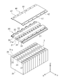
- FIG. 1 is a perspective view showing the appearance of the battery module 100 according to the embodiment
- FIG. 2 is an exploded perspective view of a part of the battery module 100.
- the battery module 100 includes a battery laminate 2, a rectangular parallelepiped housing 10, a duct plate 30, a cover plate 40, a light emitting unit 50, and a light receiving unit 60.
- the housing 10 includes end plates 11 located at both ends of the battery stack 2 in the stacking direction, side plates 12 that sandwich the end plates 11 and cover the side surfaces of the battery stack 2, and a base plate that covers the bottom of the battery stack 2. It is composed of 13.
- the battery laminate 2 is housed inside the housing 10 and is covered by the duct plate 30 and the cover plate 40.
- the stacking direction of the batteries is the X direction
- the direction intersecting the X directions and corresponding to the side of the batteries is the Y direction
- the direction intersecting the X and Y directions is the Z direction.
- the stacking direction (X direction) of the batteries corresponds to the first direction in the claim
- the Y direction intersecting the X direction corresponds to the second direction in the claim.
- the battery laminate 2 is configured by laminating a plurality of batteries 20 along the X direction.
- a spacer formed of a resin material or the like in the shape of a sheet or a plate may be arranged between the batteries to electrically insulate the batteries.
- Each battery 20 is a rechargeable secondary battery such as a lithium ion battery, a nickel-hydrogen battery, or a nickel-cadmium battery.
- each battery 20 is a so-called square battery, and has a flat rectangular parallelepiped outer can 21.
- a substantially rectangular opening (not shown) is provided on one surface of the outer can 21, and an electrode body, an electrolytic solution, or the like is housed in the outer can 21 through this opening.
- a sealing plate 21a for closing the opening of the outer can 21 is provided.
- the output terminal 22 of the positive electrode is arranged near one end in the longitudinal direction, and the output terminal 22 of the negative electrode is arranged near the other end.
- the pair of output terminals 22 are electrically connected to the positive electrode plate and the negative electrode plate constituting the electrode body, respectively.
- the output terminal 22 of the positive electrode will be referred to as a positive electrode terminal 22a
- the output terminal 22 of the negative electrode will be referred to as a negative electrode terminal 22b.
- the positive electrode terminal 22a and the negative electrode terminal 22b are collectively referred to as an output terminal 22.
- Each output terminal 22 is inserted into a through hole (not shown) formed in the sealing plate 21a.
- An insulating sealing member (not shown) is interposed between each output terminal 22 and each through hole.
- the sealing plate 21a is the upper surface of the battery 20, and the bottom surface of the outer can 21 facing the sealing plate 21a is the lower surface of the battery 20.
- the battery 20 has two main surfaces connecting the upper surface and the lower surface.
- This main surface is the surface having the largest area among the six surfaces of the battery 20.
- the main surface is a long side that is connected to the long sides of the upper and lower surfaces.
- the remaining two surfaces excluding the upper surface, the lower surface and the two main surfaces are the side surfaces of the battery 20.
- This side surface is a pair of short sides connected to the short sides of the upper surface and the lower surface.
- the sealing plate 21a is provided with a valve portion 24 between the pair of output terminals 22.
- the valve portion 24 is also called a safety valve, and is a mechanism for each battery 20 to eject the gas inside the battery.
- the valve portion 24 is configured to open when the internal pressure of the outer can 21 rises above a predetermined value so that the gas inside can be released.
- the valve portion 24 is composed of, for example, a thin-walled portion provided in a part of the sealing plate 21a and thinner than the other portion, and a linear groove formed on the surface of the thin-walled portion. In this configuration, when the internal pressure of the outer can 21 rises, the thin-walled portion is torn from the groove to open the valve.
- the valve portion 24 of each battery 20 is connected to a discharge path 33 described later, and the gas inside the battery is discharged from the valve portion 24 to the discharge path 33.
- the plurality of batteries 20 are stacked at predetermined intervals so that the main surfaces of adjacent batteries 20 face each other.
- stacking means arranging a plurality of members in any one direction. Therefore, stacking the batteries 20 includes arranging a plurality of batteries 20 horizontally.
- the batteries 20 are stacked horizontally, and the X direction, which is the stacking direction of the batteries 20, is a direction extending horizontally.
- the Y direction is horizontal and perpendicular to the X direction, and the Z direction perpendicular to the X and Y directions is the vertical direction.
- Each battery 20 is arranged so that the output terminals 22 face the same direction.
- Each battery 20 of the present embodiment is arranged so that the output terminal 22 faces upward in the vertical direction.
- FIG. 3A is a schematic view showing the case where the batteries 20 are connected in parallel
- FIG. 3B is a schematic view showing the case where the batteries 20 are connected in series.
- 3A and 3B correspond to a view of the upper surface of each of the stacked batteries 20.
- FIG. 3A when the batteries 20 are electrically connected in parallel, one positive electrode terminal 22a of the adjacent batteries 20 and the positive electrode terminal 22a of the other battery 20 are laminated so as to be adjacent to each other, and the positive electrodes or the positive electrodes are stacked.
- the negative electrodes are connected to each other by the bus bar 28.
- blocks in which four batteries 20, which are a part of the twelve batteries 20, are electrically connected in parallel are provided for three blocks, and each block is connected in series. ..
- the batteries 20 are connected in parallel, even if a voltage abnormality occurs in one battery 20, there is a case where the voltage abnormality is not detected in the entire block.
- the duct plate 30 is placed on the upper surface of the battery laminate 2.
- the duct plate 30 is a resin plate-shaped member that covers the upper surface of the battery laminate 2, that is, the surface on which the valve portion 24 of each battery 20 is arranged, and is fixed to the battery laminate 2 by, for example, the side plate 12. ..
- the duct plate 30 has a base plate 31 extending along the upper surface of the battery laminate 2, and a plurality of openings 32 for exposing the valve portion 24 are provided at positions of the base plate 31 corresponding to the valve portion 24 of each battery 20. Have. Further, the duct plate 30 has a discharge path 33 for temporarily storing the gas ejected from each battery 20.
- the discharge path 33 extends in the stacking direction X of the batteries 20 and is connected to the valve portion 24 of each battery 20. Each valve portion 24 communicates with the discharge path 33 through the opening 32.
- the discharge path 33 is defined by a shielding portion 41 of the cover plate 40 that covers the upper part of the plurality of openings 32, and a pair of wall portions 34 that surround the sides of each opening 32.
- the shielding portion 41 and the pair of wall portions 34 each have an elongated shape that is long in the X direction.
- the pair of wall portions 34 are arranged in the Y direction with the plurality of openings 32 or the plurality of valve portions 24 interposed therebetween, and the respective wall surfaces face the Y direction.
- the pair of wall portions 34 are formed so as to project from the base plate 31 toward the cover plate 40.
- the shielding portion 41 constitutes the top surface of the discharge path 33.
- each wall surface in the shielding portion 41 of the cover plate 40, the pair of wall portions 34 surrounding the sides of each opening 32, and the base plate 31 facing the discharge path 33 and partitioning the discharge path 33 reflects light.
- a color such as black to suppress.
- the color of the wall surface may be the ground color of the constituent material of each component, or may be colored by plating or painting.
- the duct plate 30 has an opening 36 that exposes the output terminal 22 at a position corresponding to the output terminal 22 of each battery 20.
- a bus bar 28 is placed in each opening 36.
- the plurality of bus bars 28 are supported by the duct plate 30. Therefore, the duct plate 30 also functions as a so-called bus bar plate.
- the output terminals 22 of the adjacent batteries 20 are electrically connected to each other by the bus bar 28 mounted on each opening 36.
- the cover plate 40 is a plate-shaped member that covers the upper part of the duct plate 30, and is placed on the upper surface of the duct plate 30.
- the cover plate 40 is made of, for example, an insulating resin.
- the cover plate 40 has a shielding portion 41 that covers the discharge path 33 and the wall portion 34 of the duct plate 30, and a terminal covering portion 42 that extends from the shielding portion 41 to both ends of the duct plate 30 in the Y direction and covers the output terminal 22 of the battery 20. Has.
- the cover plate 40 of the present embodiment is a so-called top cover that constitutes a part of the outer shell of the battery module 100, specifically, the upper surface of the battery module 100.
- the cover plate 40 suppresses contact of condensed water, dust, etc. with the output terminal 22, the valve portion 24, the bus bar 28, and the like of the battery 20.
- Both ends of the cover plate 40 in the Y direction are fixed to the duct plate 30.
- the duct plate 30 has a plurality of engaging claws 37 at both ends in the Y direction at intervals in the X direction.
- the cover plate 40 has an engaging hole 47 at a position where it overlaps with each engaging claw 37 when viewed from the Z direction, and each engaging claw 37 is inserted into each engaging hole 47 and engages with each other to form a duct. It is fixed to the plate 30.
- the cover plate 40 is fixed to the duct plate 30 by so-called snap fit, but it may be fixed to the duct plate 30 by using fasteners such as screws.
- FIG. 4 is a cross-sectional side view of a region of the battery module 100 including the duct plate 30 and the cover plate 40. Note that FIG. 4 omits the illustration of the internal structure of the battery 20.
- the battery module 100 includes a flow path portion 70.
- the flow path portion 70 is a flow path for leaking the gas in the discharge path 33 to the outside of the battery module 100.
- the discharge path 33 discharges the gas in the Y direction by being connected to the flow path portion 70 that leaks the gas in the discharge path 33 to the outside.
- the flow path portion 70 is defined by the duct plate 30 and the cover plate 40, and extends from the discharge path 33 in the Y direction (that is, the second direction in the claims).
- the flow path portions 70 are arranged on both sides in the Y direction with the discharge path 33 interposed therebetween.
- Each flow path portion 70 communicates with the discharge path 33 by a gap 71 between the wall portion 34 of the duct plate 30 and the shielding portion 41 of the cover plate 40, and is communicated with the discharge path 33 by a flow path outlet 72 arranged at the end in the Y direction. It is connected to the outside of the battery module 100.
- the gap 71 is formed so as to extend to the batteries 20 at both ends of the battery laminate 2 in the X direction.
- the flow path outlet 72 is formed as a long opening extending in the X direction corresponding to the gap 71. Therefore, the flow path portion 70 is a planar flow path that extends in the X direction and the Y direction.
- the gap 71 and the flow path outlet 72 may be partitioned so as to form a plurality of gaps and openings in the X direction.
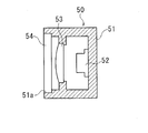
- FIG. 5 is a schematic diagram for explaining the arrangement of the light emitting unit 50 and the light receiving unit 60.
- FIG. 6A is a schematic cross-sectional view showing the configuration of the light emitting unit 50
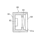
- FIG. 6B is a schematic cross-sectional view showing the configuration of the light receiving unit 60.
- the light emitting unit 50 is provided on one end side of the discharge path 33 of the battery module 100 in the X direction.
- the light receiving unit 60 faces the light emitting unit 50 and is provided on the other end side of the discharge path 33 in the X direction.
- the light emitting unit 50 is configured by providing a light source 52, an emitting lens unit 53, and a transparent window 54 in the housing 51.
- the housing 51 has an opening 51a facing the discharge path 33.
- a transparent window 54 is fitted in the opening 51a.
- the transparent window 54 transmits the light flux emitted from the light source 52 to the discharge path 33, and prevents the gas discharged from the battery 20 into the discharge path 33 from flowing into the housing 51.
- the light source 52 is, for example, a semiconductor laser, and emits light toward the discharge path 33.
- the light emitting lens unit 53 can adjust the light flux emitted from the light source 52 to an arbitrary light flux. That is, the luminous flux emitted from the light source 52 is adjusted to a parallel luminous flux as an infinite system or a luminous flux having an arbitrary diffusion angle as a finite system.
- known techniques and optical element components developed in various technical fields related to the collimation of the emitted light can be used.
- the light receiving unit 60 is configured by providing a light receiving element 62, a light receiving lens unit 63, and a transparent window 64 in the housing 61.
- the housing 61 has an opening 61a facing the discharge path 33.
- a transparent window 64 is fitted in the opening 61a. The transparent window 64 transmits the light flux from the discharge path 33 into the housing 61, and prevents the gas discharged from the battery 20 into the discharge path 33 from flowing into the housing 61.
- the light receiving element 62 is, for example, a photodiode, and detects a light flux transmitted from the discharge path 33 into the housing 61.
- the light receiving lens unit 63 adjusts the light flux transmitted into the housing 61 to an arbitrary light flux and transmits the light flux to the light receiving element 62.
- the light receiving lens unit 63 collects the light flux transmitted into the housing 61 and transmits it to the light receiving element 62, for example.
- known techniques and optical element components developed in various technical fields related to light flux condensing and the like can be used.
- the operation of the battery module 100 will be described based on the discharge and detection of the gas ejected from the battery 20.
- At least a part of the gas ejected from the battery 20 is a flammable gas.
- the gas ejected from the battery 20 also includes fine particles such as fragments of the battery structure.
- the scale of ignition outside the battery module 100 may increase.
- the gas ejected from the valve portion 24 is once discharged to the outside of the battery module 100 via the discharge path 33 and the flow path portion 70, so that the gas and fine particles are discharged to the outside of the battery module 100. The temperature can be lowered by the time it is released into the battery.
- the light emitted from the light emitting unit 50 is received by the light receiving unit 60 via the discharging path 33, but when gas is not ejected into the discharging path 33, the light receiving level is substantially constant.
- the battery module 100 outputs an alarm signal when a gas ejection is detected, and takes measures such as limiting and stopping the output of the battery module 100 based on the alarm signal, thereby enhancing the safety of the battery module. can.
- the light emitting portion 50 is provided on one end side in the X direction, which is the stacking direction of the battery laminate 2, and the light receiving portion 60 is provided on the other end side, all the batteries 20 included in the battery laminate 2 are provided. On the other hand, the gas ejection can be detected.
- the entire block is formed even in a situation where a voltage abnormality occurs in one battery 20 included in the blocks connected in parallel. In some cases, voltage abnormality is not detected. Even in such a situation, when gas is ejected from the battery 20 in which the voltage abnormality has occurred, the light emitting unit 50 and the light receiving unit 60 can detect the gas ejection and detect the abnormal state of the battery 20.
- the light emitting unit 50 can prevent the gas ejected from the discharge path 33 from flowing into the housing 51 and adhering to the light source 52.
- the light receiving unit 60 can prevent the gas ejected from the discharge path 33 from flowing into the housing 61 and adhering to the light receiving element 62.
- the light emitting unit 50 can be miniaturized and reduced in cost by using, for example, a semiconductor laser as the light source 52.
- the light emitting unit 50 is provided with an emitting lens unit 53, and the light flux emitted from the light source 52 can be adjusted to an arbitrary luminous flux, facilitating light reception by the light receiving unit 60. Can be done.
- the luminous flux emitted from the light source 52 by the emitting lens unit 53 can be adjusted to a parallel luminous flux as an infinite system, the intensity of light can be increased to a farther point.
- the luminous flux emitted from the light source 52 by the emitting lens unit 53 to a luminous flux having an arbitrary diffusion angle as a finite system, gas can be stably detected even if the position shift on the light receiving unit 60 side occurs. can do.
- the battery module 100 is mounted on a vehicle, the light incident on the light receiving unit 60 may be slightly moved by the vibration from the vehicle.
- the luminous flux to have a diffusion angle by the exit lens unit 53, it is possible to ensure that the light receiving unit 60 can always receive light even with respect to slight movements of light.
- the light receiving unit 60 is provided with a light receiving lens unit 63, and the light flux incident on the light receiving element 62 is adjusted to an arbitrary light flux to correspond to the size of the light receiving area of the light receiving element 62. Can be done.
- the discharge path 33 is partitioned by a shielding portion 41 of the cover plate 40, a pair of wall portions 34 surrounding the sides of each opening 32, and each wall surface of the base plate 31.
- Each of the above wall surfaces facing the discharge path 33 and partitioning the discharge path 33 is colored in black or the like that suppresses the reflection of light, so that the light that hits the gas is reflected by the wall surface and reaches the light receiving unit 60. Can be suppressed.
- the battery module 100 can reliably detect a decrease in the light intensity at the time of gas ejection in the light receiving unit 60.
- FIG. 7A is a schematic cross-sectional view showing the configuration of the light emitting unit 50 according to the modified example
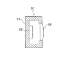
- FIG. 7B is a schematic cross-sectional view showing the configuration of the light receiving unit 60 according to the modified example.
- the light emitting unit 50 has a lens-shaped transparent window 54 in which the luminous flux emitted from the light source 52 can be adjusted to an arbitrary luminous flux.
- the transparent window 54 transmits the light flux emitted from the light source 52 to the discharge path 33, and prevents the gas discharged from the battery 20 into the discharge path 33 from flowing into the housing 51.
- the light flux emitted from the light source 52 can be adjusted to an arbitrary light flux by the transparent window 54.
- the luminous flux emitted from the light source 52 is adjusted to a parallel luminous flux as an infinite system or a luminous flux having an arbitrary diffusion angle as a finite system.
- the light emitting unit 50 can be miniaturized by providing the transparent window 54 with a function as a lens.
- the light receiving unit 60 has a lens-shaped transparent window 64 that can adjust the light flux incident on the light receiving element 62 to an arbitrary light flux.
- the transparent window 64 transmits the light flux from the discharge path 33 into the housing 61, and prevents the gas discharged from the battery 20 into the discharge path 33 from flowing into the housing 61.
- the light flux transmitted into the housing 61 can be adjusted to an arbitrary light flux by the transparent window 64.
- the light flux transmitted into the housing 61 is collected and transmitted to the light receiving element 62.
- the light receiving unit 60 can be miniaturized by providing the transparent window 64 with a function as a lens.
- FIG. 8 is a schematic cross-sectional view showing the configuration of the light emitting unit 50 according to another modified example.
- the light emitting unit 50 includes a half mirror 55 and a light amount detecting unit 56.
- the half mirror 55 reflects a part of the light from the light source 52 and causes it to enter the light amount detecting unit 56.
- the light amount detecting unit 56 detects a part of the light emitted from the light source 52 and detects the intensity of the emitted light of the light source 52.
- the half mirror 55 transmits light other than a part of the reflected light to the discharge path 33 side.
- the half mirror 55 and the light amount detecting unit 56 are provided inside the light emitting unit 50 outside the discharge path 33, and detect the intensity of the emitted light from the light source 52 without being affected by the gas ejected from the battery 20. can do.
- a battery laminate (2) in which a plurality of batteries (20) provided with a valve portion (24) for ejecting gas are laminated along the first direction, and a battery laminate (2).
- a light emitting unit (50) provided on one end side of the battery laminate (2) in the first direction and emitting light to the discharge path (33).
- a light receiving unit (60) provided on the other end side of the battery laminate (2) in the first direction and receiving light emitted from the light emitting unit (50).
- a battery module (100) comprising.
- the battery module (100) can detect the gas ejected from the battery (20) and enhance the safety of the battery module (100).
- [Item 2] The battery module (100) according to item 1, wherein a part of the battery (20) is electrically connected in parallel. As a result, the battery module (100) detects the gas ejection when a voltage abnormality occurs in the battery (20) contained in the blocks connected in parallel and the gas is ejected, and the battery (20) is in an abnormal state. Can be detected.
- [Item 3] The battery module (100) according to item 1 or 2, wherein each of the light emitting unit (50) and the light receiving unit (60) has a transparent window (54, 64) facing the discharge path.
- the battery module (100) can prevent the gas ejected from the discharge path (33) from adhering to the light source (52) and the light receiving element (62).
- the light emitting unit (50) includes a light source (52) and an emitting lens unit (53) capable of adjusting the luminous flux emitted from the light source (52) to an arbitrary luminous flux.
- the battery module (100) according to any one of item 3.
- the battery module (100) can easily receive light from the light receiving unit (60) by adjusting the light flux emitted from the light source (52) to an arbitrary light flux.
- Item 6 Item 4 or item 4 characterized in that the light receiving unit (60) has a light receiving element (62) and a light receiving lens unit (63) capable of adjusting the light flux incident on the light receiving element (62) to an arbitrary light flux.
- the battery module (100) can adjust the light flux incident on the light receiving element (62) to an arbitrary light flux, and can correspond to the size of the light receiving area of the light receiving element (62).
- the light emitting unit (50) has a light source (52) and has a light source (52).
- the transparent window (54) included in the light emitting unit (50) can adjust the luminous flux emitted from the light source (52) to an arbitrary luminous flux.
- the light receiving unit (60) has a light receiving element (62).
- the battery module (100) according to item 3, wherein the transparent window (64) included in the light receiving unit (60) can adjust the light flux incident on the light receiving element (62) to an arbitrary light flux. ..
- the battery module (100) can reduce the size of the light emitting unit (50) and the light receiving unit (60) by giving the transparent windows (54, 64) a function as a lens.
- the light source (52) is a semiconductor laser.
- the battery module (100) can be miniaturized and reduced in cost by using a semiconductor laser as the light source (52).
- Item 9 Item 1. The battery module (100) described. As a result, the battery module (100) can detect the intensity of the emitted light from the light source (52) without being affected by the gas ejected from the battery (20).
- the battery module (100) can reliably detect a decrease in the light intensity at the time of gas ejection at the light receiving unit (60) by suppressing the reflection of the light that hits the gas on the wall surface.
Landscapes
- Chemical & Material Sciences (AREA)
- Chemical Kinetics & Catalysis (AREA)
- Electrochemistry (AREA)
- General Chemical & Material Sciences (AREA)
- Engineering & Computer Science (AREA)
- Manufacturing & Machinery (AREA)
- Life Sciences & Earth Sciences (AREA)
- Health & Medical Sciences (AREA)
- Physics & Mathematics (AREA)
- Analytical Chemistry (AREA)
- Biochemistry (AREA)
- General Health & Medical Sciences (AREA)
- General Physics & Mathematics (AREA)
- Immunology (AREA)
- Pathology (AREA)
- Gas Exhaust Devices For Batteries (AREA)
- Battery Mounting, Suspending (AREA)
Priority Applications (3)
| Application Number | Priority Date | Filing Date | Title |
|---|---|---|---|
| CN202080096202.4A CN115066794A (zh) | 2020-03-31 | 2020-12-28 | 电池组件 |
| US17/906,356 US12467864B2 (en) | 2020-03-31 | 2020-12-28 | Battery module |
| JP2022511542A JP7671276B2 (ja) | 2020-03-31 | 2020-12-28 | 電池モジュール |
Applications Claiming Priority (2)
| Application Number | Priority Date | Filing Date | Title |
|---|---|---|---|
| JP2020064241 | 2020-03-31 | ||
| JP2020-064241 | 2020-03-31 |
Publications (1)
| Publication Number | Publication Date |
|---|---|
| WO2021199548A1 true WO2021199548A1 (ja) | 2021-10-07 |
Family
ID=77928448
Family Applications (1)
| Application Number | Title | Priority Date | Filing Date |
|---|---|---|---|
| PCT/JP2020/049218 Ceased WO2021199548A1 (ja) | 2020-03-31 | 2020-12-28 | 電池モジュール |
Country Status (4)
| Country | Link |
|---|---|
| US (1) | US12467864B2 (https=) |
| JP (1) | JP7671276B2 (https=) |
| CN (1) | CN115066794A (https=) |
| WO (1) | WO2021199548A1 (https=) |
Families Citing this family (1)
| Publication number | Priority date | Publication date | Assignee | Title |
|---|---|---|---|---|
| KR20260023162A (ko) * | 2024-08-09 | 2026-02-20 | 삼성에스디아이 주식회사 | 배터리 모듈 |
Citations (3)
| Publication number | Priority date | Publication date | Assignee | Title |
|---|---|---|---|---|
| JP2015207555A (ja) * | 2014-04-21 | 2015-11-19 | パロ アルト リサーチ センター インコーポレイテッド | 内部光学センシングに基づくバッテリマネージメント |
| JP2016054127A (ja) * | 2014-09-04 | 2016-04-14 | 株式会社Gsユアサ | 蓄電装置 |
| CN109119571A (zh) * | 2018-07-27 | 2019-01-01 | 清华大学 | 电池系统及其应用方法 |
Family Cites Families (12)
| Publication number | Priority date | Publication date | Assignee | Title |
|---|---|---|---|---|
| JPH0372683A (ja) * | 1989-08-11 | 1991-03-27 | Toshiba Corp | 反射型センサ |
| JP3263263B2 (ja) | 1994-11-24 | 2002-03-04 | キヤノン株式会社 | 光空間通信装置 |
| JP4775436B2 (ja) * | 2008-02-29 | 2011-09-21 | 日産自動車株式会社 | 電池モジュールおよび電池モジュールの製造方法 |
| RU2462794C2 (ru) * | 2008-04-11 | 2012-09-27 | Кавасаки Юкогё Кабусики Кайся | Герметичная аккумуляторная батарея прямоугольной формы и батарейный модуль, содержащий такую батарею |
| KR101093366B1 (ko) | 2008-08-11 | 2011-12-14 | 가부시키가이샤 야마다케 | 엣지 검출 장치 및 엣지 검출 장치용 라인 센서 |
| JP2010205471A (ja) * | 2009-03-02 | 2010-09-16 | Toyota Motor Corp | 安全弁開弁検知装置及び電池及び機器 |
| JP2015133169A (ja) | 2012-04-27 | 2015-07-23 | 三洋電機株式会社 | 電源装置及びこれを備える車両並びに蓄電装置 |
| US10570028B2 (en) * | 2015-03-27 | 2020-02-25 | Larq, Inc. | Device for UV-LED liquid monitoring and treatment |
| JP7042222B2 (ja) * | 2017-02-03 | 2022-03-25 | ネクセリス イノベーション ホールディングス,エルエルシー | ガス検体について監視するシステム及び方法 |
| JP7027255B2 (ja) | 2018-05-31 | 2022-03-01 | 本田技研工業株式会社 | バッテリパック |
| JP7210580B2 (ja) | 2018-06-26 | 2023-01-23 | 三洋電機株式会社 | 電源装置及びこれを備える車両 |
| KR102088682B1 (ko) * | 2018-12-28 | 2020-03-13 | 이건국 | 광량 검지식 융복합감지센서 및 이를 이용한 다기능 재해 경보장치 |
-
2020
- 2020-12-28 JP JP2022511542A patent/JP7671276B2/ja active Active
- 2020-12-28 CN CN202080096202.4A patent/CN115066794A/zh active Pending
- 2020-12-28 WO PCT/JP2020/049218 patent/WO2021199548A1/ja not_active Ceased
- 2020-12-28 US US17/906,356 patent/US12467864B2/en active Active
Patent Citations (3)
| Publication number | Priority date | Publication date | Assignee | Title |
|---|---|---|---|---|
| JP2015207555A (ja) * | 2014-04-21 | 2015-11-19 | パロ アルト リサーチ センター インコーポレイテッド | 内部光学センシングに基づくバッテリマネージメント |
| JP2016054127A (ja) * | 2014-09-04 | 2016-04-14 | 株式会社Gsユアサ | 蓄電装置 |
| CN109119571A (zh) * | 2018-07-27 | 2019-01-01 | 清华大学 | 电池系统及其应用方法 |
Also Published As
| Publication number | Publication date |
|---|---|
| JPWO2021199548A1 (https=) | 2021-10-07 |
| CN115066794A (zh) | 2022-09-16 |
| US20230136015A1 (en) | 2023-05-04 |
| US12467864B2 (en) | 2025-11-11 |
| JP7671276B2 (ja) | 2025-05-01 |
Similar Documents
| Publication | Publication Date | Title |
|---|---|---|
| EP4207462B1 (en) | Battery pack having improved gas venting path | |
| EP4145610B1 (en) | Battery module and battery pack comprising same | |
| US20220102807A1 (en) | Storage battery module | |
| CN220253415U (zh) | 电池模块和包括该电池模块的电池组 | |
| US12027678B2 (en) | Thermal runaway detection system and battery system | |
| JP7729674B2 (ja) | 電池モジュールおよびそれを含む電池パック | |
| KR102931493B1 (ko) | 전지 모듈 및 이를 포함하는 전지 팩 | |
| JP2023538320A (ja) | 電池モジュールおよびこれを含む電池パック | |
| KR20210122510A (ko) | 전지 모듈 및 이를 포함하는 전지 팩 | |
| KR20210127316A (ko) | 전지 모듈 및 이를 포함하는 전지팩 | |
| KR20230011256A (ko) | 배터리 팩 | |
| CN113614987A (zh) | 支撑体及蓄电池模块 | |
| WO2021199548A1 (ja) | 電池モジュール | |
| JP2021163633A (ja) | 電池システム | |
| KR20220000638A (ko) | 전지 모듈 및 이를 포함하는 전지 팩 | |
| CN121195401A (zh) | 电源装置 | |
| EP4131615A1 (en) | Battery module and battery pack including same | |
| EP4131617B1 (en) | Battery module and battery pack including same | |
| JP6129329B2 (ja) | 蓄電装置 | |
| EP4625665A1 (en) | Flame release prevention venting device and battery pack including same | |
| CN119208892A (zh) | 电池包 | |
| KR20230073034A (ko) | 모듈 케이스의 기밀성과 내열성을 개선한 배터리 모듈 | |
| JP2026502191A (ja) | バッテリアセンブリおよびこれを含むバッテリパック | |
| KR20250065205A (ko) | 배터리 모듈, 이를 포함하는 배터리 팩 및 자동차 | |
| JP2025128067A (ja) | 蓄電装置 |
Legal Events
| Date | Code | Title | Description |
|---|---|---|---|
| 121 | Ep: the epo has been informed by wipo that ep was designated in this application |
Ref document number: 20929037 Country of ref document: EP Kind code of ref document: A1 |
|
| ENP | Entry into the national phase |
Ref document number: 2022511542 Country of ref document: JP Kind code of ref document: A |
|
| NENP | Non-entry into the national phase |
Ref country code: DE |
|
| 122 | Ep: pct application non-entry in european phase |
Ref document number: 20929037 Country of ref document: EP Kind code of ref document: A1 |
|
| WWG | Wipo information: grant in national office |
Ref document number: 17906356 Country of ref document: US |