WO2021199165A1 - Electrical connection structure - Google Patents
Electrical connection structure Download PDFInfo
- Publication number
- WO2021199165A1 WO2021199165A1 PCT/JP2020/014583 JP2020014583W WO2021199165A1 WO 2021199165 A1 WO2021199165 A1 WO 2021199165A1 JP 2020014583 W JP2020014583 W JP 2020014583W WO 2021199165 A1 WO2021199165 A1 WO 2021199165A1
- Authority
- WO
- WIPO (PCT)
- Prior art keywords
- connector
- connection terminal
- magnetic attraction
- electrical connection
- swing arm
- Prior art date
Links
Images


Classifications
-
- B—PERFORMING OPERATIONS; TRANSPORTING
- B62—LAND VEHICLES FOR TRAVELLING OTHERWISE THAN ON RAILS
- B62J—CYCLE SADDLES OR SEATS; AUXILIARY DEVICES OR ACCESSORIES SPECIALLY ADAPTED TO CYCLES AND NOT OTHERWISE PROVIDED FOR, e.g. ARTICLE CARRIERS OR CYCLE PROTECTORS
- B62J99/00—Subject matter not provided for in other groups of this subclass
-
- H—ELECTRICITY
- H01—ELECTRIC ELEMENTS
- H01R—ELECTRICALLY-CONDUCTIVE CONNECTIONS; STRUCTURAL ASSOCIATIONS OF A PLURALITY OF MUTUALLY-INSULATED ELECTRICAL CONNECTING ELEMENTS; COUPLING DEVICES; CURRENT COLLECTORS
- H01R13/00—Details of coupling devices of the kinds covered by groups H01R12/70 or H01R24/00 - H01R33/00
- H01R13/02—Contact members
- H01R13/193—Means for increasing contact pressure at the end of engagement of coupling part, e.g. zero insertion force or no friction
-
- H—ELECTRICITY
- H01—ELECTRIC ELEMENTS
- H01R—ELECTRICALLY-CONDUCTIVE CONNECTIONS; STRUCTURAL ASSOCIATIONS OF A PLURALITY OF MUTUALLY-INSULATED ELECTRICAL CONNECTING ELEMENTS; COUPLING DEVICES; CURRENT COLLECTORS
- H01R13/00—Details of coupling devices of the kinds covered by groups H01R12/70 or H01R24/00 - H01R33/00
- H01R13/62—Means for facilitating engagement or disengagement of coupling parts or for holding them in engagement
- H01R13/639—Additional means for holding or locking coupling parts together, after engagement, e.g. separate keylock, retainer strap
Definitions
- the present invention relates to a removable electrical connection structure.
- a round terminal provided on one side is used as a receiving terminal on the other side.
- a method of connecting with a fastening member such as a bolt is adopted.
- this method it takes time and effort to tighten bolts at a plurality of bolt fastening points, and the cost has increased.
- Patent Document 1 and Patent Document 1 as an electric connection structure utilizing a magnet.
- a structure as in Patent Document 2 is disclosed.
- Patent Document 1 discloses a configuration in which magnets are arranged in each of a pair of connectors having terminals for electrical connection portions to obtain an attractive force. This configuration enables reliable connection and reliable connection maintenance, but on the other hand, when the terminals of the electrical contact part are inserted and removed, the contact resistance gradually increases due to wear of the electrical contact part, resulting in electrical connection loss. It can occur. Further, since the electric contact portion and the magnet portion are separated from each other, the attractive force of the magnet does not act on the connection itself of the electric contact portion, and the magnetic force does not sufficiently act from the viewpoint of connecting the electric contact portion. Such issues can be considered.
- Patent Document 2 similarly discloses a configuration in which a magnet assists the fitting of the connectors, but when the connectors are released from the fitting, the connectors must be pulled out against the attractive force of the magnetic force, so that the operability is operability. There is a possibility that a large amount of friction may occur in the terminal part because it is pulled out with a strong force.
- the present invention has been made in view of the prior art, and the connection is simple and reliable without fastening with a fastening member, and wear due to friction between electrical contacts during insertion and removal of the connector is reduced.
- An object of the present invention is to provide an electrical connection structure capable of reducing electrical connection loss.
- the present invention includes a first connector having a first connection terminal and a first connector.
- a second connector having a second connection terminal
- the first connection terminal and the second connection terminal are brought into contact with each other and separated from each other, and the electrical connection between the first connector and the second connector is connected.
- the direction in which the first connector is inserted into and removed from the second connector is different from the direction in which the first connection terminal and the second connection terminal are brought into contact with each other and separated from each other.
- the electric connection structure is characterized in that the first connector and the second connector are electrically connected by the movement of the second connector under the load of inserting the first connector.
- the first connection terminal and the second connection terminal are brought into contact with each other and separated from each other, and the electrical connection between the first connector and the second connector is connected.
- the direction of insertion and removal of the first connector to the second connector is different from the direction of contact and separation between the first connection terminal and the second connection terminal, so it is easy and reliable without fastening with a fastening member.
- the second connector includes a movement restricting member that regulates the movement of the first connector and a second connector member (that is swingably supported by the movement restricting member).
- the second connector member projects toward the arrangement surface side of the second connection terminal arrangement portion where the second connection terminal is arranged and the second connection terminal arrangement portion of the second connection terminal arrangement portion, and applies a load by the first connector. Equipped with a receiving arm
- the second connector member is swingably supported by the movement restricting member by a bearing portion provided at a position where the second connection terminal arrangement portion and the arm portion intersect.
- the load from the first connector is applied to the arm of the second connector member, the second connector member rotates, and the first connection terminal of the first connector and the second connection terminal of the second connector are electrically connected. Therefore, it is possible to reduce the friction between the first connection terminal and the second connection terminal and reduce the wear with a simple structure, and it is possible to further reduce the electrical connection loss.
- the first connector has a convex portion protruding toward the second connector side in a connected state between the first connection terminal and the second connection terminal.
- the second connector includes a concave portion that engages with the convex portion in a connected state between the first connection terminal and the second connection terminal. The convex portion rotates the second connector member in a direction that separates the first connection terminal and the second connection terminal when the first connector is pulled out from the second connector in the connected state.
- the convex portion of the first connector member causes the second connector member to rotate in a direction in which the first connection terminal and the second connection terminal are separated from each other. Therefore, the first connection terminal and the second connection terminal, which are the electrodes of the electrical contact portion, can be opened without rubbing, and the wear of the first connection terminal and the second connection terminal can be reduced.
- the first connector comprises a first magnetic attraction member.
- the second connector includes a second magnetic attraction member.
- the first magnetic attraction member and the second magnetic attraction member are arranged so as to generate a magnetic field and attract each other when the first connector and the second connector are connected.
- the first magnetic attraction member is provided in the first connection terminal arrangement portion, and is provided.
- the second magnetic attraction member is provided in the second connection terminal arrangement portion.
- the magnetic attraction member is provided in the terminal arrangement portion where the connection terminal is provided, a magnetic force acts in the direction of connecting the connection terminals in the vicinity of the connection terminal to more reliably achieve the electrical connection. Can be done.
- the first connection terminal is arranged so as to be sandwiched between the first magnetic attraction members.
- the second connection terminal is arranged so as to be sandwiched between the second magnetic attraction members.
- connection terminal electrodes can be reliably electrically connected without hitting one side.
- the third magnetic attraction member is provided on the side opposite to the first connector with respect to the second connector, and the third magnetic attraction member is the same as the first connector. When the second connector is not connected, it attracts each other to the second magnetic attraction member.
- the second connector member when the first connector is pulled out from the second connector, the second connector member can be maintained in the open state.
- an over-rotation prevention structure for preventing over-rotation is provided on the back surface side of the second connector.
- the second connector member when the first connector is inserted into the second connector, the second connector member can be maintained in an appropriate position where it can rotate.
- the first connector is a connector provided in the control device and connected to the second connector battery.
- control device can be easily and surely electrically connected to the connector connected to the battery.
- the electrical connection structure of the present invention the electrical connection is easily and reliably connected without fastening with the fastening member, and the wear due to friction between the electrical contacts when the connector is inserted and removed is reduced, resulting in electrical connection loss. Can be reduced.
- FIG. 2 is a cross-sectional view taken along the line III-III of FIG. It is a figure which mounts a motor PCU unit in a swing arm case. It is the figure which looked at the 2nd connector member from the swing arm case side.
- FIG. 4 is a cross-sectional view taken along the line IV-IV of FIG. It is a figure which showed the state which the pedestal of the 1st connector touched the arm part of the 2nd connector member. It is a figure which showed the state which the connection between the 1st connector and the 2nd connector was completed.
- FIGS. 1 to 11 An electrical connection structure according to an embodiment of the present invention will be described with reference to FIGS. 1 to 11.
- the electrical connection structure in this embodiment is used for the saddle-mounted electric vehicle 1.
- the orientations of the front, rear, left, right, up and down, etc. in the description of the present specification shall follow the orientation of the saddle-mounted vehicle such as the electric vehicle 1.
- the arrow FR indicates the front of the vehicle
- LH indicates the left side of the vehicle
- RH indicates the right side of the vehicle
- UP indicates the upper part of the vehicle.
- FIG. 1 is a left side view of the electric vehicle 1 according to the present embodiment.
- the front-rear, left-right, and up-down directions will be described in the direction seen by the occupant seated on the seat 17 of the electric vehicle 1.
- the electric vehicle 1 is an electric scooter having a low-floor floor portion 16, and rotates the rear wheels 23 by the driving force of a motor 62 (see FIG. 2) built in a swing arm 40 that pivotally supports the rear wheels 23. It runs by.
- the electric vehicle 1 according to the present embodiment is not limited to the electric scooter shown in FIG. 1, and can be applied to various electric saddle-type vehicles driven by a motor 62. In the following description, the scooter type electric vehicle 1 will be described.
- the electric vehicle 1 has a body frame 2 and a body cover 10 made of synthetic resin that covers the body frame 2.
- the vehicle body frame 2 includes a head pipe 3 at the front end, a down pipe 4 extending diagonally downward from the head pipe 3, a pair of left and right underframe portions 5 extending rearward from the rear end of the down pipe 4, and an underframe portion 5. It is composed of a side frame portion 6 extending diagonally upward from the rear end to the rear.
- the side frame portion 6 is composed of a rising portion 7 extending diagonally upward from the pair of left and right underframe portions 5 and a rear frame 8 extending rearward from the pair of left and right rising portions 7.
- the rear ends of the pair of left and right rear frames 8 are connected by a tail pipe portion 9.
- a front fork 11 is steerably attached to the head pipe 3.
- a steering wheel 13 is attached to the upper part of the front fork 11 via a steering stem 12.
- a front wheel 14 is attached to the lower end of the front fork 11.
- a front fender 15 that covers the front wheel 14 from above is attached to the front fork 11.
- a connecting support portion 20 including a pivot bracket 20a is provided between the under frame portion 5 and the side frame portion 6.
- the connecting support portion 20 supports the pivot shaft 21 extending in the left-right direction (vehicle width direction) of the electric vehicle 1.
- a front end portion (one end portion) of the swing arm 40 is pivotally supported on the pivot shaft 21. It extends from the pivot shaft 21 to the left side of the rear wheel 23 along the front-rear direction of the electric vehicle 1.
- the rear end (the other end) of the swing arm 40 supports the rear wheel 23.
- the swing arm 40 incorporates the motor 62 so that the motor 62 is arranged on the left side of the rear wheel 23. Therefore, the swing arm 40 is configured as a swing type power unit.
- a rear cushion 24 is connected between the rear end portion of the swing arm 40 and the rear frame 8 on the left side. Further, a rear fender 25 that covers the rear wheels 23 from above is attached to the rear frame 8. Further, another fender 26 that covers the rear wheel 23 from above between the rear fender 25 and the rear wheel 23 and is swingable together with the swing arm 40 is attached to the swing arm 40.
- the rear frame 8 supports the seat 17 on which the occupant sits from below.
- the battery 29 of the electric vehicle 1 is arranged in the space between the seat 17 and the pivot shaft 21 and between the pair of left and right rising portions 7.
- the battery 29 is supported by a pair of left and right start-up portions 7, a rear frame 8, and a pipe 18 that connects the start-up portions 7 in the front.
- a PCU (power control unit) 75 as an electronic component built in the swing arm 40 is arranged in front of the rear wheel 23 and diagonally below the rear of the battery 29 (see FIG. 2).
- the PCU 75 is configured to include an inverter and the like, converts DC power supplied from the battery 29 via the feeder line 58 into AC power, and supplies the returned AC power to the motor 62. Further, when the motor 62 is regenerated, the PCU 75 converts the AC power generated by the motor 62 into DC power and charges the battery 29.
- the vehicle body cover 10 is a cover that covers the vehicle body frame 2, etc., and has a front cover 10a, a steering wheel cover 10b, a leg shield 10c, a floor side cover 10d, a seat under cover 10e, a seat under cover 10e, and the like.
- the front cover 10a covers the front end portion of the vehicle body frame 2 such as the head pipe 3 from the front.
- the handle cover 10b covers the left and right central portions of the handle 13 above the front cover 10a.
- the leg shield 10c is connected to the front cover 10a and covers the head pipe 3 and the down pipe 4 from the rear.
- the seat under cover 10e covers the space under the seat 17 from the front.
- the pair of left and right floor side covers 10d are connected to the leg shield 10c and the seat under cover 10e, and cover the pair of left and right underframe portions 5 from both the left and right sides.
- the under-seat cover 10e is connected to the trailing edge of the under-seat cover 10e.
- a stand 28 is arranged on the side of the swing arm 40.
- the swing arm 40 is composed of a swing arm case 41 and a swing arm cover 42 that covers the swing arm case 41.
- FIG. 1 shows a state in which the swing arm cover 42 is attached to the swing arm case 41
- FIG. 2 shows a state in which the swing arm cover 42 is removed.
- the motor PCU unit 60 is housed in the unit storage chamber 41a in the swing arm case 41.
- the motor 62 and the PCU 75 are electrically connected by a three-phase feeder line 70, and are integrated by a unit base 61 to form a motor PCU unit 60.
- the motor 62 of the motor PCU unit 60 includes a motor case 63 including a part of the unit base 61 and a motor cover 64, and a stator 65 and a rotor 66 as a drive unit incorporated therein. It is composed of.
- the motor cover 64 is fixed to the unit base 61 with bolts 71.
- a motor shaft 67 that rotates integrally with the rotor 66 is rotatably supported by a unit base 61 and a motor cover 64 via bearings 69.
- the right end portion 67R of the motor shaft 67 is arranged so as to project to the right of the motor case 63.
- a motor gear 68 is formed on the right end portion 67R.
- the reducer 43 is arranged in the reducer accommodating chamber 41d composed of the swing arm case 41 and the gear case cover 35.
- the intermediate shaft 44 of the speed reducer 43 is rotatably supported by the bearing 48, and the intermediate gear 45 attached to the intermediate shaft 44 meshes with the motor gear 68 of the motor shaft 67.
- the gear portion 44a provided on the intermediate shaft 44 meshes with the output gear 46 attached to the axle 23a of the rear wheel 23, and the power from the motor 62 is decelerated via the speed reducer 43 to reduce the rear wheel 23.
- the rear wheel 23 rotates together with the wheel 23b which is transmitted to the axle 23a and fixed integrally with the axle 23a.
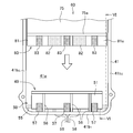
- the PCU 75 of the motor PCU unit 60 is provided with the first connector 80 on the end face on the side to be inserted into the swing arm case 41.
- the swing arm case 41 has a substantially circular portion in which the motor 62 is housed and a substantially rectangular shape in which the PCU 75 is housed in the left side view of the vehicle.
- the unit storage chamber 41a of the swing arm case 41 in which the motor PCU unit 60 is housed is surrounded by a peripheral wall portion 41b and a peripheral wall portion 41b at predetermined heights. It is composed of a bottom 41c.
- the peripheral wall portion 41b includes a front wall portion 41b 1 located in the front, a pair of side wall portions 41b 2 extending substantially at right angles from both ends of the front wall portion 41b 1 , and both side wall portions 41b 2 . It is composed of a curved curved wall portion 41b 3 that connects them.
- the front wall portion 41b 1 of the swing arm case 41 is provided with a second connector 50 that is connected to and disconnected from the first connector 80.
- the first connector 80 provided at the end opposite to the motor 62 of the PCU 75 is attached to the second connector 50 provided in the swing arm case 41.
- the motor gear 68 provided on the motor shaft 67 protruding from the right side of the motor case 63 of the motor PCU unit 60 is connected to the intermediate gear 45 of the speed reducer 43 arranged in the swing arm case 41.
- the motor 62 and the speed reducer 43 are connected by sliding and engaging.
- the swing arm case 41 serves as a member that regulates the movement of the motor PCU unit 60. Then, as shown in FIGS. 2 and 3, the motor PCU unit 60 is fixed to the swing arm case 41 with bolts 72.
- the second connector 50 provided in the swing arm case 41 and the first connector 80 provided in the motor PCU unit 60 are connected / disconnected.
- the second connector 50 is electrically connected to the battery 29 by a feeder line 58, and when the first connector 80 is connected to the second connector 50, power is supplied to the PCU 75 and the motor 62.
- the PCU75 of the motor PCU unit 60 has a box shape, and a feeder line 70 is attached to one end thereof, and is electrically connected to the motor 62 by the feeder line 70. ing.
- a first connector 80 is provided at the other end of the PCU 75.
- the first connector 80 includes a rectangular plate-shaped pedestal 81 that is provided so as to project from the PCU 75.
- the first connection terminal 82 which is an electrode, is attached to the surface of the pedestal 81 opposite to the swing arm case 41.
- two first connection terminals 82 are provided, but one may be used, or two or more terminals 82 may be provided.
- a first magnet 83 as a first magnetic attraction member is fixed to both sides of the first connection terminal 82.
- the second connector 50 provided in the swing arm case 41 is a support shaft that serves as a support portion that swingably supports the second connector member 51 and the second connector member 51. It has 55.
- the second connector member 51 is formed to have a width close to the width of the pedestal 81 of the first connector 80.
- the second connector member 51 includes a second connection terminal arrangement portion 51a and an arm portion 51b, and is formed in a substantially L shape in a side view.
- two second connection terminals 52 are attached to the second connection terminal arrangement portion 51a of the second connector member 51 at positions corresponding to the first connection terminals 82 of the first connector 80. ing.
- a second magnet 53 as a second magnetic attraction member is attached to both sides of the second connection terminal 52.
- the second connection terminal 52 and the second magnet 53 are arranged at positions corresponding to the first connection terminal 82 and the first magnet 83, respectively, when the first connector 80 is connected to the second connector 50.
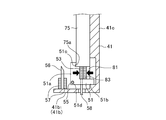
- a feeder line 58 is connected to the second connection terminal 52. As shown in FIGS. 4 and 6, the feeder line 58 passes through the second connector member 51, penetrates the front wall portion 41b 1 of the swing arm case 41, and is connected to the battery 29.
- the arm portion 51b of the second connector member 51 is formed so as to project from the second connection terminal arrangement portion 51a toward the arrangement surface side of the second connection terminal 52, and the first connector 80 Is designed to receive the load of the first connector 80 when it is inserted into the second connector 50.
- the second connector member 51 has an insertion hole 51d through which the support shaft 55 is inserted at a position where the second connection terminal arrangement portion 51a and the arm portion 51b intersect.
- the support shaft 55 is attached to both side wall portions 41b 2 of the swing arm case 41, and the second connector member 51 is swingably supported with respect to the swing arm case 41.
- the support shaft 55 is fixed to a pair of side wall portions 41b 2 of the swing arm case 41 so as to be parallel to the front wall portion 41b 1, and the second connector member 51 swings freely to the swing arm case 41. It is supported.
- a stopper member 56 as an over-rotation prevention structure for preventing the second connector member 51 from rotating and over-rotating. Is provided so as to protrude.
- the stopper member 56 is a pin-shaped protrusion, and as shown in FIG. 5, three stopper members 56 are provided in the present embodiment, but the number thereof can be appropriately changed.
- a third magnet 57 as a third magnetic attraction member is arranged adjacent to the stopper member 56.
- the tip of the stopper member 56 is formed on a slope so that when the second connector member 51 rotates and comes into contact with the second connector member 51, the second connector member 51 comes into contact with the second connector member 51 in a stable manner.
- the third magnet 57 is arranged at a position where it attracts the second magnet 53 when the second connector member 51 rotates and comes into contact with the stopper member 56.
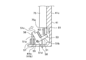
- the first connector 80 is formed with a convex portion 75a protruding toward the second connector side in the connected state between the first connection terminal 82 and the second connection terminal 52.
- the convex portion 75a is formed at the front end, which is the insertion side of the PCU 75 into the swing arm case 41.
- the second connection terminal arrangement portion 51a of the second connector 50 includes a concave portion 51c that engages with the convex portion 75a in the connected state between the first connection terminal 82 and the second connection terminal 52, and the convex portion 75a is in the connected state.
- the motor PCU unit 60 is moved in the direction of bringing the first connector 80 closer to the second connector 50 so as to be housed in the unit storage chamber 41a of the swing arm case 41.
- the pedestal 81 of the first connector 80 comes into contact with the arm portion 51b of the second connector member 51, and the arm portion 51b receives the load from the first connector 80.
- the second connector member 51 begins to rotate in the direction approaching the first connector 80.
- the convex portion 75a provided on the PCU 75 presses the wall portion 51c 1 of the concave portion 51c of the second connector member 51 with the first magnet 83.
- the second connector member 51 begins to rotate in a direction away from the first connection terminal 82 and the first magnet 83 of the first connector 80 against the attractive force with the second magnet 53.
- the connector member 51 stops at a predetermined angle and does not rotate any further.
- the arm portion 51b of the second connector member 51 is set to the first connector. It is set at an angle that can receive a load from 80.
- the stopper member 56 When the rotation of the second connector member 51 is stopped by the stopper member 56 , the third magnet 57 provided on the front wall portion 41b 1 of the swing arm case 41 and the second magnet 53 of the second connector member 51 attract each other.
- the second connector member 51 maintains a state of a predetermined angle. In this way, the second connector member 51 is maintained in a predetermined position, so that when the first connector 80 is connected to the second connector 50 next time, the arm portion 51b of the second connector member 51 becomes the first connector 80. Since it can receive the load from, the first connector 80 can be reliably connected to the second connector 50.
- the motor PCU unit 60 is inserted into and removed from the swing arm case 41 in the front-rear direction in the vehicle.
- the first connector 80 is the first. The direction of insertion and removal from the two connectors 50 and the direction of contact and separation between the first connection terminal 82 and the second connection terminal 52 are different.
- the electrical connection structure of the present embodiment includes a first connector 80 having a first connection terminal 82 and a second connector 50 having a second connection terminal 52, and the first connector 80 is pulled out to the second connector 50.
- the first connection terminal 82 and the second connection terminal 52 come into contact with each other and separate from each other, and the electrical connection between the first connector 80 and the second connector 50 is connected and disconnected, and the second of the first connector 80 is connected.
- the direction of insertion and removal from the connector 50 and the direction of contact and separation between the first connection terminal 82 and the second connection terminal 52 are different, and the movement of the second connector 50 under the load of inserting the first connector 80 causes the first connector.
- the 80 and the second connector 50 are electrically connected, they can be easily and securely connected without fastening with bolts, and the electrical contacts when the first connector 80 and the second connector 50 are inserted and removed. It is possible to reduce the wear caused by the friction between the first connection terminal 82 and the second connection terminal 52, which are the parts, and reduce the electrical connection loss.
- the second connector 50 includes a swing arm case 41 as a movement restricting member for restricting the movement of the first connector 80, and a second connector member 51 swingably supported by the swing arm case 41.
- the two connector member 51 projects toward the arrangement surface side of the second connection terminal arrangement portion 51a in which the second connection terminal 52 is arranged and the second connection terminal 52 of the second connection terminal arrangement portion 51a, and applies the load by the first connector 80.
- the second connector member 51 is provided with a receiving arm portion 51b, and the second connector member 51 can swing freely to the swing arm case 41 by a support shaft 55 as a support portion provided at a position where the second connection terminal arrangement portion 51a and the arm portion 51b intersect.
- the first connector 80 has a convex portion 75a protruding toward the second connector 50 in the connected state between the first connection terminal 82 and the second connection terminal 52, and the second connector 50 is connected to the first connection terminal 82.
- a concave portion 51c that engages with the convex portion 75a in the connected state with the second connection terminal 52 is provided, and the convex portion 75a is the first connection terminal when the first connector 80 is pulled out from the second connector 50 in the connected state. Since the second connector member 51 is rotated in the direction in which the 82 and the second connection terminal 52 are separated from each other, the first connection terminal 82 and the second connection terminal 52, which are the electrodes of the electrical contact portion, should be opened without rubbing. It is possible to reduce the wear of the first connection terminal 82 and the second connection terminal 52.
- the first connector 80 includes a first magnet 83
- the second connector 50 includes a second magnet 53
- the first magnet 83 and the second magnet 53 have a magnetic field when the first connector 80 and the second connector 50 are connected.
- the first magnet 83 is provided in the first connection terminal arrangement portion 81a
- the second magnet 53 is provided in the second connection terminal arrangement portion 51a. In the vicinity of the first connection terminal 82 and the second connection terminal 52, a magnetic force acts in the direction of connecting the first connection terminal 82 and the second connection terminal 52, and an electrical connection can be achieved more reliably.
- first connection terminal 82 is arranged so as to be sandwiched between the first magnet 83 and the second connection terminal 52 is arranged so as to be sandwiched between the second magnet 53, the first connection terminal 82 and the second connection are connected. Since the magnetic force acts to help the terminals 52 come into contact with each other on the surface, the first connection terminal 82 and the second connection terminal 52 can be reliably electrically connected without one-sided contact.
- the first connector and 80 are provided with a third magnet 57 located on the opposite side of the second connector 50, and the third magnet 57 is a second magnet when the first connector 80 and the second connector 50 are not connected. Since they attract each other with 53, when the first connector 80 is pulled out from the second connector 50, the second magnet 53 of the second connector is attracted by the third magnet 57 to keep the second connector member 51 in the open state. be able to.
- the stopper member 56 as an over-rotation prevention structure for preventing over-rotation is provided on the back side of the second connector 50, when the first connector 80 is inserted into the second connector 50, the second connector member 51 It can be maintained in an appropriate position where it can rotate under the load from the first connector 80.
- the PCU 75 since the first connector 80 is provided on the PCU 75 and the second connector 50 is a connector connected to the battery 29, the PCU 75 can be easily connected to the connector connected to the battery 29. An electrical connection can be made reliably.
- the second connector member 51 is rotated by the load inserted into the second connector 50 of the first connector 80, and the first connection terminal 82 and the second connection terminal 52 are connected to each other.
- the crank mechanism, the link mechanism, etc. are made to work by the load of inserting the first connector into the second connector, and the first connector is seconded through these mechanisms.
- the second connector may be moved in parallel toward the first connector so as to be electrically connected / disconnected so as to be different from the direction of insertion into the connector.
- the left-right arrangement of the illustrated embodiment has been described, but even if the left-right arrangement is different, it is included in the present invention as long as it is within the scope of the gist of the invention.
Abstract
Provided is an electrical connection structure comprising a first connector 80 that has a first connection terminal 82, and a second connector 50 that has a second connection terminal 52. The first connection terminal 82 and the second connection terminal 52 come into contact with or separate from each other, and electrical connection between the first connector 80 and the second connector 50 is made or disconnected due to the insertion/removal of the first connector 80 to/from the second connector 50. The contact and separation directions of the first connection terminal 82 and the second connection terminal 52 differ from insertion/removal direction of the first connector 80 to/from the second connector 50. The first connector 80 and the second connector 50 are electrically connected due to the movement of the second connector 50 that has received the load of inserting the first connector 80. A simple and reliable connection can be made without fastening with a fastening member, wear caused by wear between the electrical contact parts when removing and inserting the electrical contact portions is reduced, and electrical connection loss can be lowered.
Description
本発明は、着脱可能な電気接続構造に関する。
The present invention relates to a removable electrical connection structure.
従来、例えば、PCU(パワーコントロールユニット)とバッテリコネクタの接続や、モータとPCUの接続方法等の着脱式の電気接続構造においては、一側方に設けた丸型端子を他方側の受け側端子にボルト等の締結部材により接続するといった手法が採用されている。しかしながら、この手法では、複数のボルト締結箇所に対してボルト締めを行うといった手間がかかり、コストが増大していた。
Conventionally, in a detachable electrical connection structure such as a connection between a PCU (power control unit) and a battery connector or a connection method between a motor and a PCU, a round terminal provided on one side is used as a receiving terminal on the other side. A method of connecting with a fastening member such as a bolt is adopted. However, in this method, it takes time and effort to tighten bolts at a plurality of bolt fastening points, and the cost has increased.
この課題を解決するために、締結部材による締結を行わずに、上記のような電気部品同士電気接続構造において、簡易かつ確実に接続する手法として、磁石を活用した電気接続構造として特許文献1や特許文献2のような構造が開示されている。
In order to solve this problem, as a method for simply and surely connecting electric parts to each other in the above-mentioned electric connection structure without fastening with a fastening member, Patent Document 1 and Patent Document 1 as an electric connection structure utilizing a magnet. A structure as in Patent Document 2 is disclosed.
特許文献1では、電気的接続部分の端子を有した一対のコネクタのそれぞれに磁石を配置して吸着力を得る構成が開示されている。この構成によれば確実な接続と確実な接続維持を可能とするが、一方で電気接点部の端子を抜き挿しする際に、電気接点部が摩耗により次第に接触抵抗が大きくなり、電気接続ロスが発生する可能性がある。また、電気接点部分と磁石部分の配置が離れていることにより電気接点部分の接続自体に磁石の吸着力が働かず、電気接点部分の接続といった観点では、磁力の力が十分に作用していないといった課題が考えられる。
特許文献2では、同様に磁石でコネクタの嵌合をアシストする構成が開示されているが、コネクタ同士の嵌合を解除する際は、磁力による吸引力に反して抜かなくてはならないので操作性が悪く、また強い力で引き抜くので端子部に大きな摩擦が生じる可能性がある。Patent Document 1 discloses a configuration in which magnets are arranged in each of a pair of connectors having terminals for electrical connection portions to obtain an attractive force. This configuration enables reliable connection and reliable connection maintenance, but on the other hand, when the terminals of the electrical contact part are inserted and removed, the contact resistance gradually increases due to wear of the electrical contact part, resulting in electrical connection loss. It can occur. Further, since the electric contact portion and the magnet portion are separated from each other, the attractive force of the magnet does not act on the connection itself of the electric contact portion, and the magnetic force does not sufficiently act from the viewpoint of connecting the electric contact portion. Such issues can be considered.
Patent Document 2 similarly discloses a configuration in which a magnet assists the fitting of the connectors, but when the connectors are released from the fitting, the connectors must be pulled out against the attractive force of the magnetic force, so that the operability is operability. There is a possibility that a large amount of friction may occur in the terminal part because it is pulled out with a strong force.
特許文献2では、同様に磁石でコネクタの嵌合をアシストする構成が開示されているが、コネクタ同士の嵌合を解除する際は、磁力による吸引力に反して抜かなくてはならないので操作性が悪く、また強い力で引き抜くので端子部に大きな摩擦が生じる可能性がある。
本発明はかかる従来技術に鑑み成されたものであって、締結部材による締結を行わずに、簡易かつ確実に接続するとともに、コネクタの抜き挿しの際における電気接点部同士の摩擦による摩耗を減少させて、電気接続ロスを低減することのできる電気接続構造を提供
を課題とする。 The present invention has been made in view of the prior art, and the connection is simple and reliable without fastening with a fastening member, and wear due to friction between electrical contacts during insertion and removal of the connector is reduced. An object of the present invention is to provide an electrical connection structure capable of reducing electrical connection loss.
を課題とする。 The present invention has been made in view of the prior art, and the connection is simple and reliable without fastening with a fastening member, and wear due to friction between electrical contacts during insertion and removal of the connector is reduced. An object of the present invention is to provide an electrical connection structure capable of reducing electrical connection loss.
上記の課題を解決するために、本発明は、第一接続端子を有する第一コネクタと、
第二接続端子を有する第二コネクタと、を備え、
前記第一コネクタが前記第二コネクタに抜き挿しされることによって、前記第一接続端子と前記第二接続端子とが当接・離間し、前記第一コネクタと前記第二コネクタの電気接続が接続、解除され、
前記第一コネクタの前記第二コネクタへの抜き挿し方向と、前記第一接続端子と前記第二接続端子の当接・離間方向は異なり、
前記第一コネクタの挿す荷重を受けた前記第二コネクタの動きにより、前記第一コネクタと前記第二コネクタが電気的に接続されることを特徴とする電気接続構造である。 In order to solve the above problems, the present invention includes a first connector having a first connection terminal and a first connector.
With a second connector having a second connection terminal,
When the first connector is inserted into and removed from the second connector, the first connection terminal and the second connection terminal are brought into contact with each other and separated from each other, and the electrical connection between the first connector and the second connector is connected. , Released,
The direction in which the first connector is inserted into and removed from the second connector is different from the direction in which the first connection terminal and the second connection terminal are brought into contact with each other and separated from each other.
The electric connection structure is characterized in that the first connector and the second connector are electrically connected by the movement of the second connector under the load of inserting the first connector.
上記構成によれば、第一コネクタが第二コネクタに抜き挿しされることによって、第一接続端子と第二接続端子とが当接・離間し、第一コネクタと第二コネクタの電気接続が接続、解除され、第一コネクタの第二コネクタへの抜き挿し方向と、第一接続端子と第二接続端子の当接・離間方向は異なるので、締結部材による締結を行わずに、簡易かつ確実に接続するとともに、第一コネクタと第二コネクタとのの抜き挿しの際の電気接点部である接続端子同士の摩擦による摩耗を減少させて、電気接続ロスを低減させることができる。
According to the above configuration, when the first connector is inserted into and removed from the second connector, the first connection terminal and the second connection terminal are brought into contact with each other and separated from each other, and the electrical connection between the first connector and the second connector is connected. , The direction of insertion and removal of the first connector to the second connector is different from the direction of contact and separation between the first connection terminal and the second connection terminal, so it is easy and reliable without fastening with a fastening member. In addition to connecting, it is possible to reduce wear due to friction between connection terminals, which are electrical contact portions when the first connector and the second connector are inserted and removed, and reduce electrical connection loss.
本発明の好適な実施形態によれば、前記第二コネクタは、前記第一コネクタの移動を規制する移動規制部材と、前記移動規制部材に揺動自在に支持される第二コネクタ部材(とを備え、
前記第二コネクタ部材は、前記第二接続端子が配置される第二接続端子配置部と、前記第二接続端子配置部の前記第二接続端子の配置面側に突出し前記第一コネクタによる荷重を受ける腕部とを備え、
前記第二コネクタ部材は、前記第二接続端子配置部と前記腕部との交わる位置に設けられた支承部により前記移動規制部材に揺動自在に支承され、
前記第一コネクタが前記移動規制部材により移動が規制された状態になると、前記第一コネクタの荷重により前記第二コネクタ部材が回動して、前記第一コネクタと前記第二コネクタ(50)が電気的に接続される。 According to a preferred embodiment of the present invention, the second connector includes a movement restricting member that regulates the movement of the first connector and a second connector member (that is swingably supported by the movement restricting member). Prepare,
The second connector member projects toward the arrangement surface side of the second connection terminal arrangement portion where the second connection terminal is arranged and the second connection terminal arrangement portion of the second connection terminal arrangement portion, and applies a load by the first connector. Equipped with a receiving arm
The second connector member is swingably supported by the movement restricting member by a bearing portion provided at a position where the second connection terminal arrangement portion and the arm portion intersect.
When the movement of the first connector is restricted by the movement restricting member, the second connector member is rotated by the load of the first connector, and the first connector and the second connector (50) are moved. It is electrically connected.
前記構成によれば、 第一コネクタによる荷重が第二コネクタ部材の腕部にかかり、第二コネクタ部材が回動して第一コネクタの第一接続端子と第二コネクタの第二接続端子が電気的に接続されるので、簡易な構造で第一接続端子と第二接続端子同士の摩擦を低減して摩耗を減少させることができ、電気接続ロスをより低減することができる。
According to the above configuration, the load from the first connector is applied to the arm of the second connector member, the second connector member rotates, and the first connection terminal of the first connector and the second connection terminal of the second connector are electrically connected. Therefore, it is possible to reduce the friction between the first connection terminal and the second connection terminal and reduce the wear with a simple structure, and it is possible to further reduce the electrical connection loss.
本発明の好適な実施形態によれば、前記第一コネクタは、前記第一接続端子と前記第二接続端子との接続状態において、第二コネクタ側に突出する凸部を有し、
前記第二コネクタは、前記第一接続端子と前記第二接続端子との接続状態において、前記凸部と係合する凹部を備え、
前記凸部は、接続状態における前記第二コネクタから前記第一コネクタを引き抜く際に、前記第一接続端子と前記第二接続端子とを離間させる方向に前記第二コネクタ部材を回動させる。 According to a preferred embodiment of the present invention, the first connector has a convex portion protruding toward the second connector side in a connected state between the first connection terminal and the second connection terminal.
The second connector includes a concave portion that engages with the convex portion in a connected state between the first connection terminal and the second connection terminal.
The convex portion rotates the second connector member in a direction that separates the first connection terminal and the second connection terminal when the first connector is pulled out from the second connector in the connected state.
前記構成によれば、第一コネクタを第二コネクタから引き抜く際に、第一コネクタ部材の凸部により、第二コネクタ部材が第一接続端子と第二接続端子とを離間させる方向に回動するので、電気接点部分の電極である第一接続端子と第二接続端子をこすることなく開放することができ、第一接続端子および第二接続端子の摩耗を低減することができる。
According to the above configuration, when the first connector is pulled out from the second connector, the convex portion of the first connector member causes the second connector member to rotate in a direction in which the first connection terminal and the second connection terminal are separated from each other. Therefore, the first connection terminal and the second connection terminal, which are the electrodes of the electrical contact portion, can be opened without rubbing, and the wear of the first connection terminal and the second connection terminal can be reduced.
本発明の好適な実施形態によれば、前記第一コネクタは、第一磁性吸引部材を備え、
前記第二コネクタは、第二磁性吸引部材を備え、
前記第一磁性吸引部材と前記第二磁性吸引部材は、前記第一コネクタと前記第二コネクタの接続時に磁場を生成するとともに互いに吸引されるように配置され、
前記第一磁性吸引部材は、第一接続端子配置部に設けられ、
前記第二磁性吸引部材は、第二接続端子配置部に設けられる。 According to a preferred embodiment of the present invention, the first connector comprises a first magnetic attraction member.
The second connector includes a second magnetic attraction member.
The first magnetic attraction member and the second magnetic attraction member are arranged so as to generate a magnetic field and attract each other when the first connector and the second connector are connected.
The first magnetic attraction member is provided in the first connection terminal arrangement portion, and is provided.
The second magnetic attraction member is provided in the second connection terminal arrangement portion.
前記構成によれば、接続端子が設けられる端子配置部に磁性吸引部材を設けたので、接続端子の近傍で接続端子同士を接続する方向に磁力が働き、より確実に電気的接続を達成することができる。
According to the above configuration, since the magnetic attraction member is provided in the terminal arrangement portion where the connection terminal is provided, a magnetic force acts in the direction of connecting the connection terminals in the vicinity of the connection terminal to more reliably achieve the electrical connection. Can be done.
本発明の好適な実施形態によれば、前記第一接続端子は、前記第一磁性吸引部材に挟まれるように配置され、
前記第二接続端子は、前記第二磁性吸引部材に挟まれるように配置される。 According to a preferred embodiment of the present invention, the first connection terminal is arranged so as to be sandwiched between the first magnetic attraction members.
The second connection terminal is arranged so as to be sandwiched between the second magnetic attraction members.
前記構成によれば、接続端子同士が面で接触することを助けるように磁力が働くので、接続端子電極が片当たりせず確実に電気的接続することが可能となる。
According to the above configuration, since the magnetic force acts to help the connection terminals come into contact with each other on the surface, the connection terminal electrodes can be reliably electrically connected without hitting one side.
本発明の好適な実施形態によれば、前記第二コネクタに対して前記第一コネクタとは反対側に位置する第三磁性吸引部材を備え、前記第三磁性吸引部材は、前記第一コネクタと前記第二コネクタとが未接続状態において、前記第二磁性吸引部材と互いに引き合う。
According to a preferred embodiment of the present invention, the third magnetic attraction member is provided on the side opposite to the first connector with respect to the second connector, and the third magnetic attraction member is the same as the first connector. When the second connector is not connected, it attracts each other to the second magnetic attraction member.
前記構成によれば、第一コネクタを第二コネクタから引き抜いた際に、第二コネクタ部材を開放状態に維持することができる。
According to the above configuration, when the first connector is pulled out from the second connector, the second connector member can be maintained in the open state.
本発明の好適な実施形態によれば、第二コネクタの背面側に、過回転を防止する過回転防止構造を備える。
According to a preferred embodiment of the present invention, an over-rotation prevention structure for preventing over-rotation is provided on the back surface side of the second connector.
前記構成によれば、第一コネクタを第二コネクタに差し込む際に、第二コネクタ部材を回転できる適切な位置に維持することができる。
According to the above configuration, when the first connector is inserted into the second connector, the second connector member can be maintained in an appropriate position where it can rotate.
本発明の好適な実施形態によれば、前記第一コネクタは、制御装置に設けられ、前記第二コネクタバッテリに接続されたコネクである。
According to a preferred embodiment of the present invention, the first connector is a connector provided in the control device and connected to the second connector battery.
前記構成によれば制御装置をバッテリに接続されたコネクタに簡易かつ確実に電気的接続をすることができる。
According to the above configuration, the control device can be easily and surely electrically connected to the connector connected to the battery.
本発明の電気接続構造によれば、締結部材による締結を行わずに、簡易かつ確実に接続するとともに、コネクタの抜き挿しの際の電気接点部同士の摩擦による摩耗を減少させて、電気接続ロスを低減させることができる。
According to the electrical connection structure of the present invention, the electrical connection is easily and reliably connected without fastening with the fastening member, and the wear due to friction between the electrical contacts when the connector is inserted and removed is reduced, resulting in electrical connection loss. Can be reduced.
図1から図11に基づいて、本発明の一実施の形態に係る電気接続構造について説明する。本実施形態における電気接続構造は、鞍乗型の電動車両1に用いられている。
なお、本明細書記載における前後左右上下等の向きは、電動車両1等の鞍乗型車両の、車両の向きに従うものとする。また、図中矢印FRは車両前方を、LHは車両左方を、RHは車両右方を、UPは車両上方を、それぞれ示す。 An electrical connection structure according to an embodiment of the present invention will be described with reference to FIGS. 1 to 11. The electrical connection structure in this embodiment is used for the saddle-mountedelectric vehicle 1.
The orientations of the front, rear, left, right, up and down, etc. in the description of the present specification shall follow the orientation of the saddle-mounted vehicle such as theelectric vehicle 1. In the figure, the arrow FR indicates the front of the vehicle, LH indicates the left side of the vehicle, RH indicates the right side of the vehicle, and UP indicates the upper part of the vehicle.
なお、本明細書記載における前後左右上下等の向きは、電動車両1等の鞍乗型車両の、車両の向きに従うものとする。また、図中矢印FRは車両前方を、LHは車両左方を、RHは車両右方を、UPは車両上方を、それぞれ示す。 An electrical connection structure according to an embodiment of the present invention will be described with reference to FIGS. 1 to 11. The electrical connection structure in this embodiment is used for the saddle-mounted
The orientations of the front, rear, left, right, up and down, etc. in the description of the present specification shall follow the orientation of the saddle-mounted vehicle such as the
図1は、本実施形態に係る電動車両1の左側面図である。なお、以下の説明では、電動車両1のシート17に着座した乗員の見た方向において、前後、左右及び上下の方向を説明する。
FIG. 1 is a left side view of the electric vehicle 1 according to the present embodiment. In the following description, the front-rear, left-right, and up-down directions will be described in the direction seen by the occupant seated on the seat 17 of the electric vehicle 1.
電動車両1は、低床のフロア部16を有する電動スクータであり、後輪23を軸支するスイングアーム40に内蔵されたモータ62(図2参照)の駆動力で後輪23を回転駆動させることにより走行する。なお、本実施形態に係る電動車両1は、図1の電動スクータに限定されることはなく、モータ62によって駆動する各種の電動の鞍乗型車両に適用可能である。以下の説明では、スクータ型の電動車両1について説明する。
The electric vehicle 1 is an electric scooter having a low-floor floor portion 16, and rotates the rear wheels 23 by the driving force of a motor 62 (see FIG. 2) built in a swing arm 40 that pivotally supports the rear wheels 23. It runs by. The electric vehicle 1 according to the present embodiment is not limited to the electric scooter shown in FIG. 1, and can be applied to various electric saddle-type vehicles driven by a motor 62. In the following description, the scooter type electric vehicle 1 will be described.
電動車両1は、車体フレーム2と、車体フレーム2を覆う合成樹脂製の車体カバー10とを有する。車体フレーム2は、前端部のヘッドパイプ3と、ヘッドパイプ3から後ろ斜め下方に延びるダウンパイプ4と、ダウンパイプ4の後端から後方に延びる左右一対のアンダーフレーム部5と、アンダーフレーム部5の後端から後ろ斜め上方に延びるサイドフレーム部6とから構成される。サイドフレーム部6は、左右一対のアンダーフレーム部5から後ろ斜め上方に延びる立ち上げ部7と、左右一対の立ち上げ部7から後方に延出するリヤフレーム8とから構成される。左右一対のリヤフレーム8の後端は、テールパイプ部9で連結されている。
The electric vehicle 1 has a body frame 2 and a body cover 10 made of synthetic resin that covers the body frame 2. The vehicle body frame 2 includes a head pipe 3 at the front end, a down pipe 4 extending diagonally downward from the head pipe 3, a pair of left and right underframe portions 5 extending rearward from the rear end of the down pipe 4, and an underframe portion 5. It is composed of a side frame portion 6 extending diagonally upward from the rear end to the rear. The side frame portion 6 is composed of a rising portion 7 extending diagonally upward from the pair of left and right underframe portions 5 and a rear frame 8 extending rearward from the pair of left and right rising portions 7. The rear ends of the pair of left and right rear frames 8 are connected by a tail pipe portion 9.
ヘッドパイプ3には、フロントフォーク11が操舵自在に取り付けられている。フロントフォーク11の上部には、ステアリングステム12を介して、ハンドル13が取り付けられている。フロントフォーク11の下端には、前輪14が取り付けられている。フロントフォーク11には、前輪14を上方から覆うフロントフェンダ15が取り付けられている。
A front fork 11 is steerably attached to the head pipe 3. A steering wheel 13 is attached to the upper part of the front fork 11 via a steering stem 12. A front wheel 14 is attached to the lower end of the front fork 11. A front fender 15 that covers the front wheel 14 from above is attached to the front fork 11.
アンダーフレーム部5とサイドフレーム部6との間には、ピボットブラケット20aを含む連結支持部20が設けられている。連結支持部20は、電動車両1の左右方向(車幅方向)に延びるピボット軸21を支持する。ピボット軸21には、スイングアーム40の前端部(一端部)が軸支されている。ピボット軸21から電動車両1の前後方向に沿って、後輪23の左側方に延びている。スイングアーム40の後端部(他端部)は、後輪23を支持する。
A connecting support portion 20 including a pivot bracket 20a is provided between the under frame portion 5 and the side frame portion 6. The connecting support portion 20 supports the pivot shaft 21 extending in the left-right direction (vehicle width direction) of the electric vehicle 1. A front end portion (one end portion) of the swing arm 40 is pivotally supported on the pivot shaft 21. It extends from the pivot shaft 21 to the left side of the rear wheel 23 along the front-rear direction of the electric vehicle 1. The rear end (the other end) of the swing arm 40 supports the rear wheel 23.
スイングアーム40は、後輪23の左側方にモータ62が配置されるように、該モータ62を内蔵する。従って、スイングアーム40は、スイング式のパワーユニットとして構成される。スイングアーム40の後端部と左側のリヤフレーム8との間には、リヤクッション24が連結されている。また、リヤフレーム8には、後輪23を上方から覆うリヤフェンダ25が取り付けられている。さらに、スイングアーム40には、リヤフェンダ25と後輪23との間で後輪23を上方から覆い、且つ、スイングアーム40と共に揺動可能な他のフェンダ26が取り付けられている。
The swing arm 40 incorporates the motor 62 so that the motor 62 is arranged on the left side of the rear wheel 23. Therefore, the swing arm 40 is configured as a swing type power unit. A rear cushion 24 is connected between the rear end portion of the swing arm 40 and the rear frame 8 on the left side. Further, a rear fender 25 that covers the rear wheels 23 from above is attached to the rear frame 8. Further, another fender 26 that covers the rear wheel 23 from above between the rear fender 25 and the rear wheel 23 and is swingable together with the swing arm 40 is attached to the swing arm 40.
リヤフレーム8は、乗員が着座するシート17を下側から支持する。シート17とピボット軸21との間で、左右一対の立ち上げ部7の間の空間には、電動車両1のバッテリ29が配置されている。バッテリ29は、左右一対の立ち上げ部7及びリヤフレーム8と、立ち上げ部7を前方で連結するパイプ18によって支持されている。
The rear frame 8 supports the seat 17 on which the occupant sits from below. The battery 29 of the electric vehicle 1 is arranged in the space between the seat 17 and the pivot shaft 21 and between the pair of left and right rising portions 7. The battery 29 is supported by a pair of left and right start-up portions 7, a rear frame 8, and a pipe 18 that connects the start-up portions 7 in the front.
後輪23の前方にあって、バッテリ29の後ろ斜め下方の箇所には、スイングアーム40に内蔵された電子部品としてのPCU(パワーコントロールユニット)75が配設されている(図2参照)。PCU75は、インバータ等を含み構成され、バッテリ29から給電線58を介して供給される直流電力を交流電力に変換し、返還後の交流電力をモータ62に供給する。また、PCU75は、モータ62の回生時には、モータ62が発電した交流電力を直流電力に変換し、バッテリ29に充電する。
A PCU (power control unit) 75 as an electronic component built in the swing arm 40 is arranged in front of the rear wheel 23 and diagonally below the rear of the battery 29 (see FIG. 2). The PCU 75 is configured to include an inverter and the like, converts DC power supplied from the battery 29 via the feeder line 58 into AC power, and supplies the returned AC power to the motor 62. Further, when the motor 62 is regenerated, the PCU 75 converts the AC power generated by the motor 62 into DC power and charges the battery 29.
車体カバー10は、車体フレーム2等を覆うカバーであって、フロントカバー10a、ハンドルカバー10b、レッグシールド10c、フロアサイドカバー10d、シート下カバー10e及びシート下カバー10e等を有する。フロントカバー10aは、ヘッドパイプ3等の車体フレーム2の前端部を前方から覆う。ハンドルカバー10bは、フロントカバー10aの上方で、ハンドル13の左右中央部を覆う。レッグシールド10cは、フロントカバー10aに接続され、ヘッドパイプ3及びダウンパイプ4を後方から覆う。シート下カバー10eは、シート17下方の空間を前方から覆う。
The vehicle body cover 10 is a cover that covers the vehicle body frame 2, etc., and has a front cover 10a, a steering wheel cover 10b, a leg shield 10c, a floor side cover 10d, a seat under cover 10e, a seat under cover 10e, and the like. The front cover 10a covers the front end portion of the vehicle body frame 2 such as the head pipe 3 from the front. The handle cover 10b covers the left and right central portions of the handle 13 above the front cover 10a. The leg shield 10c is connected to the front cover 10a and covers the head pipe 3 and the down pipe 4 from the rear. The seat under cover 10e covers the space under the seat 17 from the front.
左右一対のフロアサイドカバー10dは、レッグシールド10c及びシート下カバー10eに連結され、左右一対のアンダーフレーム部5を左右両側から覆う。シート下カバー10eは、シート下カバー10eの後縁部に接続されている。スイングアーム40の側方には、スタンド28が配設されている。
The pair of left and right floor side covers 10d are connected to the leg shield 10c and the seat under cover 10e, and cover the pair of left and right underframe portions 5 from both the left and right sides. The under-seat cover 10e is connected to the trailing edge of the under-seat cover 10e. A stand 28 is arranged on the side of the swing arm 40.
スイングアーム40は、スイングアームケース41と、スイングアームケース41を覆うスイングアームカバー42とから構成されている。図1はスイングアームケース41にスイングアームカバー42が取り付けられた状態を示し、図2は、スイングアームカバー42が取り外された状態を示している。
The swing arm 40 is composed of a swing arm case 41 and a swing arm cover 42 that covers the swing arm case 41. FIG. 1 shows a state in which the swing arm cover 42 is attached to the swing arm case 41, and FIG. 2 shows a state in which the swing arm cover 42 is removed.
図2に示されるように、スイングアームケース41内のユニット収容室41aには、モータPCUユニット60が収容される。モータ62とPCU75とは三相線の給電線70により電位的に接続されており、ユニット基部61により一体にされて、モータPCUユニット60を構成する。
As shown in FIG. 2, the motor PCU unit 60 is housed in the unit storage chamber 41a in the swing arm case 41. The motor 62 and the PCU 75 are electrically connected by a three-phase feeder line 70, and are integrated by a unit base 61 to form a motor PCU unit 60.
モータPCUユニット60のモータ62は、図3に示されるように、ユニット基部61の一部とモータカバー64とからなるモータケース63と、その内部に組み込まれた駆動部としてのステータ65およびロータ66で構成されている。モータカバー64はユニット基部61に、ボルト71で固定されている。ロータ66と一体に回転するモータ軸67が、ベアリング69を介してユニット基部61とモータカバー64に回転自在に支承されている。モータ軸67の右端部67Rは、モータケース63の右方に突出されて配置されている。右端部67Rにはモータギヤ68が形成されている。
As shown in FIG. 3, the motor 62 of the motor PCU unit 60 includes a motor case 63 including a part of the unit base 61 and a motor cover 64, and a stator 65 and a rotor 66 as a drive unit incorporated therein. It is composed of. The motor cover 64 is fixed to the unit base 61 with bolts 71. A motor shaft 67 that rotates integrally with the rotor 66 is rotatably supported by a unit base 61 and a motor cover 64 via bearings 69. The right end portion 67R of the motor shaft 67 is arranged so as to project to the right of the motor case 63. A motor gear 68 is formed on the right end portion 67R.
スイングアームケース41とギヤケースカバー35で構成される減速機収容室41dには、減速機43が配設されている。減速機43の中間軸44は、ベアリング48に回転自在に支承され、中間軸44に取り付けられた中間ギヤ45は、モータ軸67のモータギヤ68と噛合う。中間軸44に設けられたギヤ部44aは、後輪23の車軸23aに取り付けられた出力ギヤ46と噛合っており、モータ62からの動力は、減速機43を介して減速して後輪23の車軸23aに伝達され、車軸23aと一体に固定されたホイール23bと共に後輪23が回転する。
The reducer 43 is arranged in the reducer accommodating chamber 41d composed of the swing arm case 41 and the gear case cover 35. The intermediate shaft 44 of the speed reducer 43 is rotatably supported by the bearing 48, and the intermediate gear 45 attached to the intermediate shaft 44 meshes with the motor gear 68 of the motor shaft 67. The gear portion 44a provided on the intermediate shaft 44 meshes with the output gear 46 attached to the axle 23a of the rear wheel 23, and the power from the motor 62 is decelerated via the speed reducer 43 to reduce the rear wheel 23. The rear wheel 23 rotates together with the wheel 23b which is transmitted to the axle 23a and fixed integrally with the axle 23a.
図4に示されるように、モータPCUユニット60のPCU75は、スイングアームケース41に挿入する側の端面に第一コネクタ80が設けられている。
As shown in FIG. 4, the PCU 75 of the motor PCU unit 60 is provided with the first connector 80 on the end face on the side to be inserted into the swing arm case 41.
スイングアームケース41は、図2に示されるように、車両における左側面視において、モータ62が収容される部分は略円形にされ、PCU75が収容される部分は略矩形状に形成されている。
モータPCUユニット60が収容されるスイングアームケース41のユニット収容室41aは、図2、図3および図6に示されるように、所定の高さで周壁部41bと、周壁部41bで囲われた底部41cとで構成されている。周壁部41bは、図2に示されるように、前方に位置した前壁部41b1と、前壁部41b1の両端から略直角に伸びる一対の側壁部41b2と、両側壁部41b2を繋ぐ曲線状の曲壁部41b3とで構成されている。スイングアームケース41の前壁部41b1に、第一コネクタ80と接続・解除される第二コネクタ50が設けられている。 As shown in FIG. 2, theswing arm case 41 has a substantially circular portion in which the motor 62 is housed and a substantially rectangular shape in which the PCU 75 is housed in the left side view of the vehicle.
As shown in FIGS. 2, 3 and 6, theunit storage chamber 41a of the swing arm case 41 in which the motor PCU unit 60 is housed is surrounded by a peripheral wall portion 41b and a peripheral wall portion 41b at predetermined heights. It is composed of a bottom 41c. As shown in FIG. 2, the peripheral wall portion 41b includes a front wall portion 41b 1 located in the front, a pair of side wall portions 41b 2 extending substantially at right angles from both ends of the front wall portion 41b 1 , and both side wall portions 41b 2 . It is composed of a curved curved wall portion 41b 3 that connects them. The front wall portion 41b 1 of the swing arm case 41 is provided with a second connector 50 that is connected to and disconnected from the first connector 80.
モータPCUユニット60が収容されるスイングアームケース41のユニット収容室41aは、図2、図3および図6に示されるように、所定の高さで周壁部41bと、周壁部41bで囲われた底部41cとで構成されている。周壁部41bは、図2に示されるように、前方に位置した前壁部41b1と、前壁部41b1の両端から略直角に伸びる一対の側壁部41b2と、両側壁部41b2を繋ぐ曲線状の曲壁部41b3とで構成されている。スイングアームケース41の前壁部41b1に、第一コネクタ80と接続・解除される第二コネクタ50が設けられている。 As shown in FIG. 2, the
As shown in FIGS. 2, 3 and 6, the
モータPCUユニット60をスイングアームケース41に取り付ける際には、PCU75のモータ62と反対側の端部に設けられた第一コネクタ80を、スイングアームケース41内に設けられた第二コネクタ50に取り付けて電気的に接続するとともに、モータPCUユニット60のモータケース63の右面から突出したモータ軸67に設けられたモータギヤ68を、スイングアームケース41内に配設された減速機43の中間ギヤ45にスライドして噛合させて、モータ62と減速機43とを連結させる。スイングアームケース41は、モータPCUユニット60の移動を規制する部材としての役割を果たしている。その後、図2および図3に示されるように、モータPCUユニット60をスイングアームケース41に、ボルト72で固定する。
When attaching the motor PCU unit 60 to the swing arm case 41, the first connector 80 provided at the end opposite to the motor 62 of the PCU 75 is attached to the second connector 50 provided in the swing arm case 41. The motor gear 68 provided on the motor shaft 67 protruding from the right side of the motor case 63 of the motor PCU unit 60 is connected to the intermediate gear 45 of the speed reducer 43 arranged in the swing arm case 41. The motor 62 and the speed reducer 43 are connected by sliding and engaging. The swing arm case 41 serves as a member that regulates the movement of the motor PCU unit 60. Then, as shown in FIGS. 2 and 3, the motor PCU unit 60 is fixed to the swing arm case 41 with bolts 72.
このようにモータPCUユニット60の着脱により、スイングアームケース41内に設けられ第二コネクタ50と、モータPCUユニット60に設けられた第一コネクタ80とが接続・解除される。第二コネクタ50はバッテリ29と給電線58で電気的に接続されており、第二コネクタ50に第一コネクタ80を接続するとPCU75およびモータ62に電力が供給される。
By attaching / detaching the motor PCU unit 60 in this way, the second connector 50 provided in the swing arm case 41 and the first connector 80 provided in the motor PCU unit 60 are connected / disconnected. The second connector 50 is electrically connected to the battery 29 by a feeder line 58, and when the first connector 80 is connected to the second connector 50, power is supplied to the PCU 75 and the motor 62.
次に、モータPCUユニット60に設けられた第一コネクタ80と、スイングアームケース41に設けられた第二コネクタ50との電気接続構造について詳しく説明する。
Next, the electrical connection structure between the first connector 80 provided in the motor PCU unit 60 and the second connector 50 provided in the swing arm case 41 will be described in detail.
図2に示されるように、モータPCUユニット60のPCU75は、箱型の形状をしており、一方の端部には給電線70が取り付けられ、給電線70によりモータ62に電気的に接続されている。
As shown in FIG. 2, the PCU75 of the motor PCU unit 60 has a box shape, and a feeder line 70 is attached to one end thereof, and is electrically connected to the motor 62 by the feeder line 70. ing.
図4および図5に示されるように、PCU75の他端には、第一コネクタ80が設けられている。第一コネクタ80は、PCU75から突出して設けられた矩形形状の板状の台座81を備えている。台座81のスイングアームケース41とは反対側の面には、電極である第一接続端子82が取り付けられている。本実施の形態では、第一接続端子82は2つ設けられているが、1つでもよいし、2個以上の複数でもよい。第一接続端子82の両脇には、第一磁性吸着部材としての第一磁石83が固定されている。
As shown in FIGS. 4 and 5, a first connector 80 is provided at the other end of the PCU 75. The first connector 80 includes a rectangular plate-shaped pedestal 81 that is provided so as to project from the PCU 75. The first connection terminal 82, which is an electrode, is attached to the surface of the pedestal 81 opposite to the swing arm case 41. In the present embodiment, two first connection terminals 82 are provided, but one may be used, or two or more terminals 82 may be provided. A first magnet 83 as a first magnetic attraction member is fixed to both sides of the first connection terminal 82.
スイングアームケース41に設けられた第二コネクタ50は、図4に示されるように、第二コネクタ部材51と、第二コネクタ部材51を揺動自在に支持する支承部としての役割を果たす支持軸55を備えている。
As shown in FIG. 4, the second connector 50 provided in the swing arm case 41 is a support shaft that serves as a support portion that swingably supports the second connector member 51 and the second connector member 51. It has 55.
第二コネクタ部材51は、図4に示されるように、第一コネクタ80の台座81の幅に近い幅に形成されている。第二コネクタ部材51は、図6に示されるように、第二接続端子配置部51aと腕部51bを備え、側面視で略L字形状に形成されている。
As shown in FIG. 4, the second connector member 51 is formed to have a width close to the width of the pedestal 81 of the first connector 80. As shown in FIG. 6, the second connector member 51 includes a second connection terminal arrangement portion 51a and an arm portion 51b, and is formed in a substantially L shape in a side view.
第二コネクタ部材51の第二接続端子配置部51aには、図5に示されるように、第一コネクタ80の第一接続端子82に対応する位置に、第二接続端子52が2個取り付けられている。第二接続端子52の両側に、第二磁性吸引部材としての第二磁石53が取り付けられている。第二接続端子52および第二磁石53は、第一コネクタ80が第二コネクタ50に接続した際に、それぞれ第一接続端子82および第一磁石83に対応する位置に配設されている。第二接続端子52には給電線58が接続されている。図4および図6に示されるように、給電線58は、第二コネクタ部材51内を通り、スイングアームケース41の前壁部41b1を貫通して、バッテリ29に接続されている。
As shown in FIG. 5, two second connection terminals 52 are attached to the second connection terminal arrangement portion 51a of the second connector member 51 at positions corresponding to the first connection terminals 82 of the first connector 80. ing. A second magnet 53 as a second magnetic attraction member is attached to both sides of the second connection terminal 52. The second connection terminal 52 and the second magnet 53 are arranged at positions corresponding to the first connection terminal 82 and the first magnet 83, respectively, when the first connector 80 is connected to the second connector 50. A feeder line 58 is connected to the second connection terminal 52. As shown in FIGS. 4 and 6, the feeder line 58 passes through the second connector member 51, penetrates the front wall portion 41b 1 of the swing arm case 41, and is connected to the battery 29.
第二コネクタ部材51の腕部51bは、図6に示されるように、第二接続端子配置部51aから第二接続端子52の配置面側に突出するように形成されており、第一コネクタ80が第二コネクタ50に挿される際に、第一コネクタ80の荷重を受けるようになっている。
As shown in FIG. 6, the arm portion 51b of the second connector member 51 is formed so as to project from the second connection terminal arrangement portion 51a toward the arrangement surface side of the second connection terminal 52, and the first connector 80 Is designed to receive the load of the first connector 80 when it is inserted into the second connector 50.
第二コネクタ部材51は、第二接続端子配置部51aと腕部51bとの交わる位置に、支持軸55が挿通される挿通孔51dが形成されている。支持軸55は、図5に示されるように、スイングアームケース41の両方の側壁部41b2に取り付けられており、第二コネクタ部材51は、スイングアームケース41に対して揺動自在に支承される。支持軸55は、スイングアームケース41の一対の側壁部41b2に、前壁部41b1と平行になるように固定されており、第二コネクタ部材51は、スイングアームケース41に揺動自在に支持されている。
The second connector member 51 has an insertion hole 51d through which the support shaft 55 is inserted at a position where the second connection terminal arrangement portion 51a and the arm portion 51b intersect. As shown in FIG. 5, the support shaft 55 is attached to both side wall portions 41b 2 of the swing arm case 41, and the second connector member 51 is swingably supported with respect to the swing arm case 41. NS. The support shaft 55 is fixed to a pair of side wall portions 41b 2 of the swing arm case 41 so as to be parallel to the front wall portion 41b 1, and the second connector member 51 swings freely to the swing arm case 41. It is supported.
図6に示されるように、スイングアームケース41の前壁部41b1の内壁面には、第二コネクタ部材51が回動して過回転することを防止する過回転防止構造としてのストッパ部材56が突出して設けられている。ストッパ部材56はピン状の突起であって、図5に示されるように、本実施の形態では3か所設けられているが、その数は適宜変更することができる。
As shown in FIG. 6, on the inner wall surface of the front wall portion 41b 1 of the swing arm case 41, a stopper member 56 as an over-rotation prevention structure for preventing the second connector member 51 from rotating and over-rotating. Is provided so as to protrude. The stopper member 56 is a pin-shaped protrusion, and as shown in FIG. 5, three stopper members 56 are provided in the present embodiment, but the number thereof can be appropriately changed.
図6に示されるように、ストッパ部材56に隣接して第三磁性吸引部材としての第三磁石57が配置されている。ストッパ部材56の先端は、第二コネクタ部材51が回動して当接した際に、第二コネクタ部材51が安定して当接するように斜面に形成されている。第三磁石57は、第二コネクタ部材51が回動してストッパ部材56に当接した際に、第二磁石53と互いに引き合う位置に配設されている。
As shown in FIG. 6, a third magnet 57 as a third magnetic attraction member is arranged adjacent to the stopper member 56. The tip of the stopper member 56 is formed on a slope so that when the second connector member 51 rotates and comes into contact with the second connector member 51, the second connector member 51 comes into contact with the second connector member 51 in a stable manner. The third magnet 57 is arranged at a position where it attracts the second magnet 53 when the second connector member 51 rotates and comes into contact with the stopper member 56.
図8に示されるように、第一コネクタ80には、第一接続端子82と第二接続端子52との接続状態において、第二コネクタ側に突出する凸部75aが形成されている。凸部75aはPCU75のスイングアームケース41への挿入側である前端に形成されている。第二コネクタ50の第二接続端子配置部51aは、第一接続端子82と第二接続端子52との接続状態において、凸部75aと係合する凹部51cを備え、凸部75aは、接続状態における第二コネクタ50から第一コネクタ80を引き抜く際に、第一接続端子82と第二接続端子52とを離間させる方向に第二コネクタ部材51を回動させる形状に形成されている。
As shown in FIG. 8, the first connector 80 is formed with a convex portion 75a protruding toward the second connector side in the connected state between the first connection terminal 82 and the second connection terminal 52. The convex portion 75a is formed at the front end, which is the insertion side of the PCU 75 into the swing arm case 41. The second connection terminal arrangement portion 51a of the second connector 50 includes a concave portion 51c that engages with the convex portion 75a in the connected state between the first connection terminal 82 and the second connection terminal 52, and the convex portion 75a is in the connected state. When the first connector 80 is pulled out from the second connector 50 in the above, the second connector member 51 is formed to rotate in a direction in which the first connection terminal 82 and the second connection terminal 52 are separated from each other.
次に、第一コネクタ80を第二コネクタ50に抜き挿して、第一コネクタ80と第二コネクタ50との電気接続が接続・解除される動作について、図4ないし図11に基づいて説明する。
Next, the operation of inserting and removing the first connector 80 into the second connector 50 and connecting / disconnecting the electrical connection between the first connector 80 and the second connector 50 will be described with reference to FIGS. 4 to 11.
第一コネクタ80と第二コネクタ50とが電気的に接続される動作について説明する。図4および図6に示されるように、モータPCUユニット60を、スイングアームケース41のユニット収容室41a内に収めるように、第一コネクタ80を第二コネクタ50に近づける方向に移動させる。図7に示されるように、第一コネクタ80の台座81が第二コネクタ部材51の腕部51bに当接して、腕部51bは第一コネクタ80からの荷重を受ける。第二コネクタ部材51が、第一コネクタ80に近づく方向に回動をし始める。
The operation of electrically connecting the first connector 80 and the second connector 50 will be described. As shown in FIGS. 4 and 6, the motor PCU unit 60 is moved in the direction of bringing the first connector 80 closer to the second connector 50 so as to be housed in the unit storage chamber 41a of the swing arm case 41. As shown in FIG. 7, the pedestal 81 of the first connector 80 comes into contact with the arm portion 51b of the second connector member 51, and the arm portion 51b receives the load from the first connector 80. The second connector member 51 begins to rotate in the direction approaching the first connector 80.
図2に示されるように、モータPCUユニット60がスイングアームケース41内に嵌合されるとともに、図3に示されるようにモータ62のモータ軸67が減速機43と連結されると、モータPCUユニット60の移動は規制され、第一コネクタ80の移動が規制された状態になる。第一コネクタ80の移動が規制された状態になると、図8に示されるように、第一接続端子82と第二接続端子52とは当接して接続された状態となるとともに、第一磁石83と第二磁石53とは磁力で吸引されて強固に吸着する。
As shown in FIG. 2, when the motor PCU unit 60 is fitted in the swing arm case 41 and the motor shaft 67 of the motor 62 is connected to the speed reducer 43 as shown in FIG. 3, the motor PCU The movement of the unit 60 is restricted, and the movement of the first connector 80 is restricted. When the movement of the first connector 80 is restricted, as shown in FIG. 8, the first connection terminal 82 and the second connection terminal 52 are in contact with each other and are connected to each other, and the first magnet 83 is in contact with each other. And the second magnet 53 are attracted by magnetic force and strongly attracted.
第一コネクタ80と第二コネクタ50との電気接続が解除される動作について説明する。図9に示されるように、第一コネクタ80と第二コネクタ50との電気接続が接続された状態から、第一コネクタ80の引き抜きを開始する。
The operation of disconnecting the electrical connection between the first connector 80 and the second connector 50 will be described. As shown in FIG. 9, the first connector 80 is pulled out from the state where the electrical connection between the first connector 80 and the second connector 50 is connected.
図10に示されるように、第一コネクタ80が移動を開始すると、PCU75に設けられた凸部75aが、第二コネクタ部材51の凹部51cの壁部51c1を押圧し、第一磁石83と第二磁石53との吸引力に抗って、第二コネクタ部材51は第一コネクタ80の第一接続端子82および第一磁石83から離間する方向へ回動し始める。
As shown in FIG. 10, when the first connector 80 starts moving, the convex portion 75a provided on the PCU 75 presses the wall portion 51c 1 of the concave portion 51c of the second connector member 51 with the first magnet 83. The second connector member 51 begins to rotate in a direction away from the first connection terminal 82 and the first magnet 83 of the first connector 80 against the attractive force with the second magnet 53.
図11に示されるように、第一コネクタ80が第二コネクタ50から離れ、第二コネクタ部材51が背面側に回動すると、第二コネクタ部材51の背面側がストッパ部材56に当接し、第二コネクタ部材51は所定の角度で停止して、それ以上回動することがない。第二コネクタ部材51が停止される所定の角度は、第一コネクタ80を第二コネクタ50に挿す際に、図7に示されるように、第二コネクタ部材51の腕部51bが、第一コネクタ80からの荷重を受けることができる角度に設定されている。
As shown in FIG. 11, when the first connector 80 separates from the second connector 50 and the second connector member 51 rotates to the back side, the back side of the second connector member 51 comes into contact with the stopper member 56, and the second connector member 51 comes into contact with the stopper member 56. The connector member 51 stops at a predetermined angle and does not rotate any further. At a predetermined angle at which the second connector member 51 is stopped, when the first connector 80 is inserted into the second connector 50, as shown in FIG. 7, the arm portion 51b of the second connector member 51 is set to the first connector. It is set at an angle that can receive a load from 80.
ストッパ部材56により第二コネクタ部材51の回動が停止されると、スイングアームケース41の前壁部41b1に設けられた第三磁石57と第二コネクタ部材51の第二磁石53とが吸引し合い、第二コネクタ部材51は所定の角度の状態を維持する。このように、第二コネクタ部材51が所定の位置に維持されるので、次に第一コネクタ80を第二コネクタ50に接続するときに、第二コネクタ部材51の腕部51bが第一コネクタ80からの荷重を受けることができるので確実に第一コネクタ80を第二コネクタ50に接続することができる。
When the rotation of the second connector member 51 is stopped by the stopper member 56 , the third magnet 57 provided on the front wall portion 41b 1 of the swing arm case 41 and the second magnet 53 of the second connector member 51 attract each other. The second connector member 51 maintains a state of a predetermined angle. In this way, the second connector member 51 is maintained in a predetermined position, so that when the first connector 80 is connected to the second connector 50 next time, the arm portion 51b of the second connector member 51 becomes the first connector 80. Since it can receive the load from, the first connector 80 can be reliably connected to the second connector 50.
図2、図4および図6に示されるように、モータPCUユニット60のスイングアームケース41への抜き挿しは、車両における前後方向にされる。一方、図7および図8に示されるように、第二接続端子52は、第一接続端子82に対して車両方向における左右方向に近接・離間する方向に移動するので、第一コネクタ80の第二コネクタ50への抜き挿し方向と、第一接続端子82と第二接続端子52の当接・離間方向は異なる方向にされる。
As shown in FIGS. 2, 4 and 6, the motor PCU unit 60 is inserted into and removed from the swing arm case 41 in the front-rear direction in the vehicle. On the other hand, as shown in FIGS. 7 and 8, since the second connection terminal 52 moves in the direction of approaching / separating from the first connection terminal 82 in the left-right direction in the vehicle direction, the first connector 80 is the first. The direction of insertion and removal from the two connectors 50 and the direction of contact and separation between the first connection terminal 82 and the second connection terminal 52 are different.
本発明の一実施の形態の電気接続構造は前記したように構成されているので、以下のような効果を奏する。
Since the electrical connection structure of the embodiment of the present invention is configured as described above, the following effects are obtained.
本実施の形態の電気接続構造は、第一接続端子82を有する第一コネクタ80と、第二接続端子52を有する第二コネクタ50と、を備え、第一コネクタ80が第二コネクタ50に抜き挿しされることによって、第一接続端子82と第二接続端子52とが当接・離間し、第一コネクタ80と第二コネクタ50の電気接続が接続、解除され、第一コネクタ80の第二コネクタ50への抜き挿し方向と、第一接続端子82と第二接続端子52の当接・離間方向は異なり、第一コネクタ80の挿す荷重を受けた第二コネクタ50の動きにより、第一コネクタ80と第二コネクタ50が電気的に接続されるので、ボルトによる締結を行わずに、簡易かつ確実に接続するとともに、第一コネクタ80と第二コネクタ50とのの抜き挿しの際の電気接点部である第一接続端子82と第二接続端子52との摩擦による摩耗を減少させて、電気接続ロスを低減させることができる。
The electrical connection structure of the present embodiment includes a first connector 80 having a first connection terminal 82 and a second connector 50 having a second connection terminal 52, and the first connector 80 is pulled out to the second connector 50. By inserting, the first connection terminal 82 and the second connection terminal 52 come into contact with each other and separate from each other, and the electrical connection between the first connector 80 and the second connector 50 is connected and disconnected, and the second of the first connector 80 is connected. The direction of insertion and removal from the connector 50 and the direction of contact and separation between the first connection terminal 82 and the second connection terminal 52 are different, and the movement of the second connector 50 under the load of inserting the first connector 80 causes the first connector. Since the 80 and the second connector 50 are electrically connected, they can be easily and securely connected without fastening with bolts, and the electrical contacts when the first connector 80 and the second connector 50 are inserted and removed. It is possible to reduce the wear caused by the friction between the first connection terminal 82 and the second connection terminal 52, which are the parts, and reduce the electrical connection loss.
さらに、第二コネクタ50は、第一コネクタ80の移動を規制する移動規制部材としてのスイングアームケース41と、スイングアームケース41に揺動自在に支持される第二コネクタ部材51とを備え、第二コネクタ部材51は、第二接続端子52が配置される第二接続端子配置部51aと、第二接続端子配置部51aの第二接続端子52の配置面側に突出し第一コネクタ80による荷重を受ける腕部51bとを備え、第二コネクタ部材51は、第二接続端子配置部51aと腕部51bとの交わる位置に設けられた支承部としての支持軸55によりスイングアームケース41に揺動自在に支承され、第一コネクタ80がスイングアームケース41により移動が規制された状態になると、第一コネクタ80の荷重により第二コネクタ部材51が回動して、第一コネクタ80と第二コネクタ50が電気的に接続されるので、簡易な構造で第一接続端子と第二接続端子同士の摩擦を低減して摩耗を減少させることができ、電気接続ロスをより低減することができる。
Further, the second connector 50 includes a swing arm case 41 as a movement restricting member for restricting the movement of the first connector 80, and a second connector member 51 swingably supported by the swing arm case 41. The two connector member 51 projects toward the arrangement surface side of the second connection terminal arrangement portion 51a in which the second connection terminal 52 is arranged and the second connection terminal 52 of the second connection terminal arrangement portion 51a, and applies the load by the first connector 80. The second connector member 51 is provided with a receiving arm portion 51b, and the second connector member 51 can swing freely to the swing arm case 41 by a support shaft 55 as a support portion provided at a position where the second connection terminal arrangement portion 51a and the arm portion 51b intersect. When the movement of the first connector 80 is restricted by the swing arm case 41, the second connector member 51 rotates due to the load of the first connector 80, and the first connector 80 and the second connector 50 Is electrically connected, so that the friction between the first connection terminal and the second connection terminal can be reduced and the wear can be reduced with a simple structure, and the electrical connection loss can be further reduced.
第一コネクタ80は、第一接続端子82と第二接続端子52との接続状態において、第二コネクタ50側に突出する凸部75aを有し、第二コネクタ50は、第一接続端子82と第二接続端子52との接続状態において、凸部75aと係合する凹部51cを備え、凸部75aは、接続状態における前記第二コネクタ50から第一コネクタ80を引き抜く際に、第一接続端子82と第二接続端子52とを離間させる方向に第二コネクタ部材51を回動させるので、電気接点部分の電極である第一接続端子82と第二接続端子52をこすることなく開放することができ、第一接続端子82および第二接続端子52の摩耗を低減することができる。
The first connector 80 has a convex portion 75a protruding toward the second connector 50 in the connected state between the first connection terminal 82 and the second connection terminal 52, and the second connector 50 is connected to the first connection terminal 82. A concave portion 51c that engages with the convex portion 75a in the connected state with the second connection terminal 52 is provided, and the convex portion 75a is the first connection terminal when the first connector 80 is pulled out from the second connector 50 in the connected state. Since the second connector member 51 is rotated in the direction in which the 82 and the second connection terminal 52 are separated from each other, the first connection terminal 82 and the second connection terminal 52, which are the electrodes of the electrical contact portion, should be opened without rubbing. It is possible to reduce the wear of the first connection terminal 82 and the second connection terminal 52.
第一コネクタ80は、第一磁石83を備え、第二コネクタ50は、第二磁石53を備え、第一磁石83と第二磁石53は、第一コネクタ80と第二コネクタ50の接続時に磁場を生成するとともに互いに吸引されるように配置され、第一磁石83は、第一接続端子配置部81aに設けられ、第二磁石53は、第二接続端子配置部51aに設けられているので、第一接続端子82および第二接続端子52の近傍で、第一接続端子82と第二接続端子52とを接続する方向に磁力が働き、より確実に電気的接続を達成することができる。
The first connector 80 includes a first magnet 83, the second connector 50 includes a second magnet 53, and the first magnet 83 and the second magnet 53 have a magnetic field when the first connector 80 and the second connector 50 are connected. The first magnet 83 is provided in the first connection terminal arrangement portion 81a, and the second magnet 53 is provided in the second connection terminal arrangement portion 51a. In the vicinity of the first connection terminal 82 and the second connection terminal 52, a magnetic force acts in the direction of connecting the first connection terminal 82 and the second connection terminal 52, and an electrical connection can be achieved more reliably.
第一接続端子82は、第一磁石83に挟まれるように配置され、第二接続端子52は、第二磁石53に挟まれるように配置されているので、第一接続端子82と第二接続端子52とが面で接触することを助けるように磁力が働くので、第一接続端子82と第二接続端子52とが片当たりせず確実に電気的接続することが可能となる。
Since the first connection terminal 82 is arranged so as to be sandwiched between the first magnet 83 and the second connection terminal 52 is arranged so as to be sandwiched between the second magnet 53, the first connection terminal 82 and the second connection are connected. Since the magnetic force acts to help the terminals 52 come into contact with each other on the surface, the first connection terminal 82 and the second connection terminal 52 can be reliably electrically connected without one-sided contact.
第二コネクタ50に対して第一コネクタと80は反対側に位置する第三磁石57を備え、第三磁石57は、第一コネクタ80と第二コネクタ50とが未接続状態において、第二磁石53と互いに引き合うので、第一コネクタ80を第二コネクタ50から引き抜いた際に、第二コネクタの第二磁石53が第三磁石57により吸引されて、第二コネクタ部材51を開放状態に維持することができる。
The first connector and 80 are provided with a third magnet 57 located on the opposite side of the second connector 50, and the third magnet 57 is a second magnet when the first connector 80 and the second connector 50 are not connected. Since they attract each other with 53, when the first connector 80 is pulled out from the second connector 50, the second magnet 53 of the second connector is attracted by the third magnet 57 to keep the second connector member 51 in the open state. be able to.
第二コネクタ50の背面側に、過回転を防止する過回転防止構造としてのストッパ部材56を備えているので、第一コネクタ80を第二コネクタ50に差し込む際に、第二コネクタ部材51が、第一コネクタ80からの荷重を受けて回転することのできる適切な位置に維持することができる。
Since the stopper member 56 as an over-rotation prevention structure for preventing over-rotation is provided on the back side of the second connector 50, when the first connector 80 is inserted into the second connector 50, the second connector member 51 It can be maintained in an appropriate position where it can rotate under the load from the first connector 80.
本発明の好適な実施形態によれば、 第一コネクタ80は、PCU75に設けられ、第二コネクタ50はバッテリ29に接続されたコネクタであるので、PCU75をバッテリ29に接続されたコネクタに簡易かつ確実に電気的接続をすることができる。
According to a preferred embodiment of the present invention, since the first connector 80 is provided on the PCU 75 and the second connector 50 is a connector connected to the battery 29, the PCU 75 can be easily connected to the connector connected to the battery 29. An electrical connection can be made reliably.
以上、本発明の一実施形態を説明したが、本発明は上述の実施形態に限定されるものではなく、その要旨を逸脱しない範囲で種々の設計変更が可能であり、本発明の要旨の範囲で、多様な態様で実施されるものを含むことは勿論である。
Although one embodiment of the present invention has been described above, the present invention is not limited to the above-described embodiment, and various design changes can be made without departing from the gist thereof, and the scope of the gist of the present invention. And, of course, it includes those implemented in various aspects.
本発明の一実施の形態の電気接続構造では、第一コネクタ80の第二コネクタ50へ挿す荷重により第二コネクタ部材51が回動して、第一接続端子82と第二接続端子52とが電気的に接続されるものであったが、例えば、第一コネクタを第二コネクタに挿す荷重により、クランク機構やリンク機構等が働くようにし、これらの機構を介して、第一コネクタを第二コネクタに挿す方向とは異なるように、第二コネクタを第一コネクタに向かって平行移動させて電気的に接続・解除するようにするようにしてもよい。
なお、説明の便宜上、図示の実施形態の左右配置のものについて説明したが、左右配置の異なるものであっても、発明の要旨の範囲であれば本発明に含まれる。 In the electrical connection structure of the embodiment of the present invention, thesecond connector member 51 is rotated by the load inserted into the second connector 50 of the first connector 80, and the first connection terminal 82 and the second connection terminal 52 are connected to each other. Although it was electrically connected, for example, the crank mechanism, the link mechanism, etc. are made to work by the load of inserting the first connector into the second connector, and the first connector is seconded through these mechanisms. The second connector may be moved in parallel toward the first connector so as to be electrically connected / disconnected so as to be different from the direction of insertion into the connector.
For convenience of explanation, the left-right arrangement of the illustrated embodiment has been described, but even if the left-right arrangement is different, it is included in the present invention as long as it is within the scope of the gist of the invention.
なお、説明の便宜上、図示の実施形態の左右配置のものについて説明したが、左右配置の異なるものであっても、発明の要旨の範囲であれば本発明に含まれる。 In the electrical connection structure of the embodiment of the present invention, the
For convenience of explanation, the left-right arrangement of the illustrated embodiment has been described, but even if the left-right arrangement is different, it is included in the present invention as long as it is within the scope of the gist of the invention.
50…第二コネクタ、51…第二コネクタ部材、51a…第二接続端子配置部、51c…凹部、52…第二接続端子、53…第二磁石、54…スイングアームケース、56…ストッパ部材、57…第三磁石、75…PCU、75a…凸部、80…第一コネクタ、81a…第一接続端子配置部、82…第一接続端子、83…第一磁石。
50 ... Second connector, 51 ... Second connector member, 51a ... Second connection terminal arrangement, 51c ... Recess, 52 ... Second connection terminal, 53 ... Second magnet, 54 ... Swing arm case, 56 ... Stopper member, 57 ... Third magnet, 75 ... PCU, 75a ... Convex part, 80 ... First connector, 81a ... First connection terminal arrangement part, 82 ... First connection terminal, 83 ... First magnet.
Claims (8)
- 第一接続端子(82)を有する第一コネクタ(80)と、
第二接続端子(52)を有する第二コネクタ(50)と、を備え、
前記第一コネクタ(80)が前記第二コネクタ(50)に抜き挿しされることによって、前記第一接続端子(82)と前記第二接続端子(52)とが当接・離間し、前記第一コネクタ(80)と前記第二コネクタ(50)の電気接続が接続・解除され、
前記第一コネクタ(80)の前記第二コネクタ(50)への抜き挿し方向と、前記第一接続端子(82)と前記第二接続端子(52)の当接・離間方向は異なり、
前記第一コネクタ(80)の挿す荷重を受けた前記第二コネクタ(50)の動きにより、前記第一コネクタ(80)と前記第二コネクタ(50)が電気的に接続されることを特徴とする電気接続構造。 With the first connector (80) having the first connection terminal (82),
With a second connector (50) having a second connection terminal (52),
When the first connector (80) is inserted into and removed from the second connector (50), the first connection terminal (82) and the second connection terminal (52) are brought into contact with each other and separated from each other. The electrical connection between the first connector (80) and the second connector (50) is connected / disconnected,
The direction of inserting and removing the first connector (80) into the second connector (50) and the direction of contact and separation between the first connection terminal (82) and the second connection terminal (52) are different.
The feature is that the first connector (80) and the second connector (50) are electrically connected by the movement of the second connector (50) under the load of inserting the first connector (80). Electrical connection structure. - 前記第二コネクタ(50)は、前記第一コネクタ(80)の移動を規制する移動規制部材(41)と、前記移動規制部材(41)に揺動自在に支持される第二コネクタ部材(51)とを備え、
前記第二コネクタ部材(51)は、前記第二接続端子(52)が配置される第二接続端子配置部(51a)と、前記第二接続端子配置部(51a)の前記第二接続端子(52)の配置面側に突出し前記第一コネクタ(80)による荷重を受ける腕部(51b)とを備え、
前記第二コネクタ部材(51)は、前記第二接続端子配置部(51a)と前記腕部(51b)との交わる位置に設けられた支承部(55)により前記移動規制部材(41)に揺動自在に支承され、
前記第一コネクタ(80)が前記移動規制部材(41)により移動が規制された状態になると、前記第一コネクタ(80)の荷重により前記第二コネクタ部材(51)が回動して、前記第一コネクタ(80)と前記第二コネクタ(50)が電気的に接続されることを特徴とする請求項1に記載の電気接続構造。 The second connector (50) includes a movement restricting member (41) that regulates the movement of the first connector (80) and a second connector member (51) that is swingably supported by the movement restricting member (41). ) And
The second connector member (51) includes a second connection terminal arrangement portion (51a) in which the second connection terminal (52) is arranged, and the second connection terminal (51a) of the second connection terminal arrangement portion (51a). It is provided with an arm portion (51b) that protrudes toward the placement surface side of 52) and receives a load from the first connector (80).
The second connector member (51) is shaken by the movement restricting member (41) by a support portion (55) provided at a position where the second connection terminal arrangement portion (51a) and the arm portion (51b) intersect. It is freely supported and
When the movement of the first connector (80) is restricted by the movement restricting member (41), the load of the first connector (80) causes the second connector member (51) to rotate, and the movement is restricted. The electrical connection structure according to claim 1, wherein the first connector (80) and the second connector (50) are electrically connected. - 前記第一コネクタ(80)は、前記第一接続端子(82)と前記第二接続端子(52)との接続状態において、第二コネクタ(50)側に突出する凸部(75a)を有し、
前記第二コネクタ(50)は、前記第一接続端子(82)と前記第二接続端子(52)との接続状態において、前記凸部(75a)と係合する凹部(51c)を備え、
前記凸部(75a)は、接続状態における前記第二コネクタ(50)から前記第一コネクタ(80)を引き抜く際に、前記第一接続端子(82)と前記第二接続端子(52)とを離間させる方向に前記第二コネクタ部材(51)を回動させることを特徴とする請求項2に記載の電気接続構造。 The first connector (80) has a convex portion (75a) protruding toward the second connector (50) in a connected state between the first connection terminal (82) and the second connection terminal (52). ,
The second connector (50) includes a concave portion (51c) that engages with the convex portion (75a) in a connected state between the first connection terminal (82) and the second connection terminal (52).
The convex portion (75a) connects the first connection terminal (82) and the second connection terminal (52) when the first connector (80) is pulled out from the second connector (50) in the connected state. The electrical connection structure according to claim 2, wherein the second connector member (51) is rotated in a direction of separation. - 前記第一コネクタ(80)は、第一磁性吸引部材(83)を備え、
前記第二コネクタ(50)は、第二磁性吸引部材(53)を備え、
前記第一磁性吸引部材(83)と前記第二磁性吸引部材(53)は、前記第一コネクタ(80)と前記第二コネクタ(50)の接続時に磁場を生成するとともに互いに吸引されるように配置され、
前記第一磁性吸引部材(83)は、第一接続端子配置部(81a)に設けられ、
前記第二磁性吸引部材(53)は、第二接続端子配置部(51a)に設けられることを特徴とする請求項1ないし請求項3のいずれかに記載の電気接続構造。 The first connector (80) includes a first magnetic attraction member (83).
The second connector (50) includes a second magnetic attraction member (53).
The first magnetic attraction member (83) and the second magnetic attraction member (53) generate a magnetic field when the first connector (80) and the second connector (50) are connected and are attracted to each other. Placed,
The first magnetic attraction member (83) is provided in the first connection terminal arrangement portion (81a).
The electrical connection structure according to any one of claims 1 to 3, wherein the second magnetic attraction member (53) is provided in the second connection terminal arrangement portion (51a). - 前記第一接続端子(82)は、前記第一磁性吸引部材(83)に挟まれるように配置され、
前記第二接続端子(52)は、前記第二磁性吸引部材(53)に挟まれるように配置されることを特徴とする請求項4に記載の電気接続構造。 The first connection terminal (82) is arranged so as to be sandwiched between the first magnetic attraction member (83).
The electrical connection structure according to claim 4, wherein the second connection terminal (52) is arranged so as to be sandwiched between the second magnetic attraction member (53). - 前記第二コネクタ(50)に対して前記第一コネクタ(80)とは反対側に位置する第三磁性吸引部材(57)を備え、
前記第三磁性吸引部材(57)は、前記第一コネクタ(80)と前記第二コネクタ(50)とが未接続状態において、前記第二磁性吸引部材(53)と互いに引き合うことを特徴とする請求項4または請求項5に記載の電気接続構造。 A third magnetic attraction member (57) located on the opposite side of the first connector (80) with respect to the second connector (50) is provided.
The third magnetic attraction member (57) is characterized in that the first connector (80) and the second connector (50) are attracted to each other with the second magnetic attraction member (53) in a non-connected state. The electrical connection structure according to claim 4 or 5. - 前記第二コネクタ(50)の背面側に、過回転を防止する過回転防止構造(56)を備えることを特徴とする請求項6に記載の電気接続構造。 The electrical connection structure according to claim 6, wherein an over-rotation prevention structure (56) for preventing over-rotation is provided on the back side of the second connector (50).
- 前記第一コネクタ(80)は、制御装置(75)に設けられ、前記第二コネクタ(50)はバッテリ(29)に接続されたコネクタであることを特徴とする請求項1ないし請求項7のいずれかに記載の電気接続構造。 The first connector (80) is provided in the control device (75), and the second connector (50) is a connector connected to a battery (29). The electrical connection structure described in either.
Priority Applications (4)
| Application Number | Priority Date | Filing Date | Title |
|---|---|---|---|
| PCT/JP2020/014583 WO2021199165A1 (en) | 2020-03-30 | 2020-03-30 | Electrical connection structure |
| CN202080099264.0A CN115349201A (en) | 2020-03-30 | 2020-03-30 | Electric connection structure |
| JP2022512906A JP7290800B2 (en) | 2020-03-30 | 2020-03-30 | Electrical connection structure |
| TW110109233A TWI773195B (en) | 2020-03-30 | 2021-03-16 | Electrical connection structure |
Applications Claiming Priority (1)
| Application Number | Priority Date | Filing Date | Title |
|---|---|---|---|
| PCT/JP2020/014583 WO2021199165A1 (en) | 2020-03-30 | 2020-03-30 | Electrical connection structure |
Publications (1)
| Publication Number | Publication Date |
|---|---|
| WO2021199165A1 true WO2021199165A1 (en) | 2021-10-07 |
Family
ID=77930167
Family Applications (1)
| Application Number | Title | Priority Date | Filing Date |
|---|---|---|---|
| PCT/JP2020/014583 WO2021199165A1 (en) | 2020-03-30 | 2020-03-30 | Electrical connection structure |
Country Status (4)
| Country | Link |
|---|---|
| JP (1) | JP7290800B2 (en) |
| CN (1) | CN115349201A (en) |
| TW (1) | TWI773195B (en) |
| WO (1) | WO2021199165A1 (en) |
Citations (4)
| Publication number | Priority date | Publication date | Assignee | Title |
|---|---|---|---|---|
| JPS56127684U (en) * | 1980-02-29 | 1981-09-29 | ||
| JPS62150875U (en) * | 1986-03-17 | 1987-09-24 | ||
| WO2012132582A1 (en) * | 2011-03-31 | 2012-10-04 | 本田技研工業株式会社 | Electric vehicle control device |
| JP2019185928A (en) * | 2018-04-04 | 2019-10-24 | シャープ株式会社 | Female terminals and connectors |
Family Cites Families (3)
| Publication number | Priority date | Publication date | Assignee | Title |
|---|---|---|---|---|
| WO2017130410A1 (en) * | 2016-01-29 | 2017-08-03 | ヤマハ発動機株式会社 | Electric-vehicle battery charging system |
| US10439411B2 (en) | 2016-04-30 | 2019-10-08 | Lydia Ranjini Narayanasamy | Method and apparatus for battery connection by magnetic means |
| JP7089722B2 (en) | 2017-03-16 | 2022-06-23 | Whill株式会社 | Connector structure |
-
2020
- 2020-03-30 CN CN202080099264.0A patent/CN115349201A/en active Pending
- 2020-03-30 JP JP2022512906A patent/JP7290800B2/en active Active
- 2020-03-30 WO PCT/JP2020/014583 patent/WO2021199165A1/en active Application Filing
-
2021
- 2021-03-16 TW TW110109233A patent/TWI773195B/en active
Patent Citations (4)
| Publication number | Priority date | Publication date | Assignee | Title |
|---|---|---|---|---|
| JPS56127684U (en) * | 1980-02-29 | 1981-09-29 | ||
| JPS62150875U (en) * | 1986-03-17 | 1987-09-24 | ||
| WO2012132582A1 (en) * | 2011-03-31 | 2012-10-04 | 本田技研工業株式会社 | Electric vehicle control device |
| JP2019185928A (en) * | 2018-04-04 | 2019-10-24 | シャープ株式会社 | Female terminals and connectors |
Also Published As
| Publication number | Publication date |
|---|---|
| CN115349201A (en) | 2022-11-15 |
| TWI773195B (en) | 2022-08-01 |
| JP7290800B2 (en) | 2023-06-13 |
| JPWO2021199165A1 (en) | 2021-10-07 |
| TW202147714A (en) | 2021-12-16 |
Similar Documents
| Publication | Publication Date | Title |
|---|---|---|
| JP5396532B2 (en) | Scooter type electric vehicle | |
| JP3571676B2 (en) | Mounting structure for battery case for electric bicycle | |
| WO2012043518A1 (en) | Electric two-wheeled vehicle | |
| JP2011063065A5 (en) | ||
| TWI705023B (en) | Battery compartment for vehicle | |
| WO2010109969A1 (en) | Electric straddled vehicle | |
| JPWO2019064606A1 (en) | Vehicle battery storage | |
| JPWO2019064593A1 (en) | Vehicle battery storage | |
| EP2168864A1 (en) | Saddle-ride type electric vehicle | |
| JP3050422B2 (en) | Structure of vehicle components for electric motorcycle | |
| JP6573073B2 (en) | Battery device charging structure and electric vehicle | |
| CN110091953B (en) | Electric vehicle structure | |
| WO2021199165A1 (en) | Electrical connection structure | |
| JPWO2019064601A1 (en) | Saddle type vehicle | |
| JP6791903B2 (en) | Electric vehicle | |
| CN112519951B (en) | Pedal type motorcycle | |
| JP2000043772A (en) | Motor assisted bicycle | |
| JPH05105144A (en) | Motorcycle driven by electric motor | |
| CN112004740B (en) | Electric vehicle | |
| CN100396549C (en) | Steering device for bicycle and steering device folding method | |
| JP7367496B2 (en) | saddle type vehicle | |
| JP7437361B2 (en) | saddle type vehicle | |
| JP7055216B2 (en) | Saddle-type electric vehicle | |
| JP3458610B2 (en) | Electric wheelchair | |
| JP3069807B2 (en) | Electric motorcycle |
Legal Events
| Date | Code | Title | Description |
|---|---|---|---|
| 121 | Ep: the epo has been informed by wipo that ep was designated in this application |
Ref document number: 20929441 Country of ref document: EP Kind code of ref document: A1 |
|
| ENP | Entry into the national phase |
Ref document number: 2022512906 Country of ref document: JP Kind code of ref document: A |
|
| NENP | Non-entry into the national phase |
Ref country code: DE |
|
| 122 | Ep: pct application non-entry in european phase |
Ref document number: 20929441 Country of ref document: EP Kind code of ref document: A1 |