JP6573073B2 - Battery device charging structure and electric vehicle - Google Patents
Battery device charging structure and electric vehicle Download PDFInfo
- Publication number
- JP6573073B2 JP6573073B2 JP2015197272A JP2015197272A JP6573073B2 JP 6573073 B2 JP6573073 B2 JP 6573073B2 JP 2015197272 A JP2015197272 A JP 2015197272A JP 2015197272 A JP2015197272 A JP 2015197272A JP 6573073 B2 JP6573073 B2 JP 6573073B2
- Authority
- JP
- Japan
- Prior art keywords
- battery device
- battery
- posture
- charger
- connection
- Prior art date
- Legal status (The legal status is an assumption and is not a legal conclusion. Google has not performed a legal analysis and makes no representation as to the accuracy of the status listed.)
- Active
Links
Images


Classifications
-
- B—PERFORMING OPERATIONS; TRANSPORTING
- B62—LAND VEHICLES FOR TRAVELLING OTHERWISE THAN ON RAILS
- B62M—RIDER PROPULSION OF WHEELED VEHICLES OR SLEDGES; POWERED PROPULSION OF SLEDGES OR SINGLE-TRACK CYCLES; TRANSMISSIONS SPECIALLY ADAPTED FOR SUCH VEHICLES
- B62M6/00—Rider propulsion of wheeled vehicles with additional source of power, e.g. combustion engine or electric motor
- B62M6/80—Accessories, e.g. power sources; Arrangements thereof
- B62M6/90—Batteries
Description
本発明はバッテリ装置の充電構造および電動車両に関する。 The present invention relates to a charging structure for a battery device and an electric vehicle.
電動自転車などの電動車両は、バッテリによりモータが駆動されてこの駆動力が付加されて走行できるよう構成されている。このような電動車両において、電動車両に設けられたバッテリ装着部に対して、バッテリが内蔵されたバッテリ装置が着脱自在とされ、バッテリを充電する際に、バッテリ装置を電動車両のバッテリ装着部から取り外し、電動車両とは別途に設けられている充電器にバッテリ装置を装着して充電可能に構成されているものがある(例えば特許文献1等)。この構成によれば、充電器を室内などの好きな箇所に持ち込んで充電することができるため、便利である。 An electric vehicle such as an electric bicycle is configured such that a motor is driven by a battery and this driving force is applied to travel. In such an electric vehicle, a battery device with a built-in battery is detachable from a battery mounting portion provided in the electric vehicle, and the battery device is removed from the battery mounting portion of the electric vehicle when charging the battery. There are some which are configured so as to be able to be charged by attaching a battery device to a charger provided separately from the detachable and electric vehicle (for example, Patent Document 1). According to this configuration, the charger can be brought into a favorite place such as a room and charged, which is convenient.
前記特許文献1や特許文献2等に開示されているように、この種のバッテリ装置が装着される充電器のバッテリ装着部や電動車両のバッテリ装着部には、複数の接続用端子が例えば上方などに突出する状態で配設されている場合が多い。また、この場合には、前記構成に対応してバッテリ装置の底面部において窪んだ箇所に接続用端子が上方に延びる状態で配設されている。バッテリ装置を充電器や電動車両のバッテリ装着部から取り外す際には、比較的大きな力でバッテリ装置を上方に引き抜くことで、接続用端子同士を離脱させると同時にバッテリ装置を持ち上げて取り外すように構成されている。
As disclosed in Patent Document 1,
しかし、このような構造では、バッテリ装置を充電器や電動車両のバッテリ装着部から取り外す際に、接続用端子同士を離脱させるための力とバッテリ装置を持ち上げる力とを合わせた大きな力が同時に必要となるため、バッテリ装置の取扱者に対して大きな負担を強いていた。 However, in such a structure, when removing the battery device from the battery mounting portion of the charger or electric vehicle, a large force that combines the force for separating the connection terminals and the force for lifting the battery device is required at the same time. Therefore, a heavy burden is imposed on the battery device handler.
このようなバッテリ装置の取扱者に対する負担を軽減する方法としては、例えば特許文献3に、電動車両のバッテリ装着部に、バッテリ装置を回動自在に支持する回動支持部を設け、バッテリ装置に前記回動支持部に嵌合可能な回動支点(回動部)を設けた構造が開示されている。そして、この構造によれば、バッテリ装置を取り外す際に、先ずバッテリ装着部においてバッテリ装置を回動させて接続用端子同士を離脱させた後に、バッテリ装置を持ち上げて取り外すことができる。このような構造と同様な構造を充電器のバッテリ装着部とバッテリとに採用すると、接続用端子同士を離脱させる際とバッテリ装置を持ち上げる際とのタイミングが異なっているため、比較的小さな力でバッテリ装置の取り外し作業を行える。
As a method for reducing the burden on the battery device handler, for example,
しかしながら、充電器のバッテリ装着部に、バッテリ装置を回動自在に支持する回動支持部を設けるとともに、バッテリ装置に前記回動支持部に嵌合可能な回動支点を設ける構成を採用した場合に、バッテリ装置を充電器から取り外すために回動させた際に、バッテリ装置を確実に持っていないと、バッテリ装置が充電器のバッテリ装着部から脱落してしまうおそれがある。そして、例えば、充電器を棚や靴箱の上などの比較的高い箇所に置いていた場合には、高い所から脱落したバッテリ装置が床面などに当接して損傷してしまうおそれがある。 However, when the battery mounting portion of the charger is provided with a rotation support portion that rotatably supports the battery device, and the battery device is provided with a rotation fulcrum that can be fitted to the rotation support portion. In addition, when the battery device is rotated to be removed from the charger, the battery device may fall out of the battery mounting portion of the charger unless the battery device is securely held. For example, when the charger is placed at a relatively high place such as on a shelf or shoe box, the battery device dropped from the high place may come into contact with the floor surface and be damaged.
本発明は上記課題を解決するもので、充電器や電動車両からバッテリ装置を比較的小さな力で取り外すことができるだけでなく、バッテリ装置を回動させた際に脱落してバッテリ装置が損傷することを防止できるバッテリ装置の充電構造および電動車両を提供することを目的とするものである。 The present invention solves the above-mentioned problems, and not only can the battery device be removed from the charger or the electric vehicle with a relatively small force, but also the battery device is dropped and damaged when the battery device is rotated. It is an object of the present invention to provide a charging structure for a battery device and an electric vehicle that can prevent the above.
上記課題を解決するために、本発明のバッテリ装置の充電構造は、電動車両に対して着脱自在でバッテリが内蔵されているバッテリ装置と、バッテリ装着部を有して前記バッテリ装置のバッテリを充電する充電器と、が備えられ、前記バッテリ装置と前記充電器とにそれぞれ接続用端子が設けられているバッテリ装置の充電構造であって、前記充電器のバッテリ装着部に、前記バッテリ装置を回動自在に支持する回動支持部が設けられ、前記バッテリ装置に、前記回動支持部に嵌合可能な回動部が設けられ、前記バッテリ装置が、前記充電器のバッテリ装着部に対して、前記充電器の接続用端子に前記バッテリ装置の接続用端子が接続された接続姿勢と、前記充電器の接続用端子から前記バッテリ装置の接続用端子が離脱された離脱姿勢とにわたって、回動自在に配設され、前記バッテリ装置が前記接続姿勢から前記離脱姿勢に回動された際に被当接部に当接して、前記離脱姿勢よりもさらに回動することを阻止するとともに前記離脱姿勢を保持する回動規制部が設けられていることを特徴とする。なお、前記電動車両としては電動自転車が好適であるが、これに限るものではない。 In order to solve the above-described problems, a battery device charging structure according to the present invention includes a battery device that is detachably attached to an electric vehicle and has a built-in battery, and a battery mounting portion that charges the battery of the battery device. A charging structure for the battery device in which a connection terminal is provided on each of the battery device and the charger, and the battery device is connected to a battery mounting portion of the charger. A rotation support portion is provided for movably support, and the battery device is provided with a rotation portion that can be fitted to the rotation support portion. The battery device is connected to the battery mounting portion of the charger. A connection posture in which the connection terminal of the battery device is connected to a connection terminal of the charger, and a separation posture in which the connection terminal of the battery device is detached from the connection terminal of the charger. Therefore, the battery device is rotatably disposed, and abuts against the contacted portion when the battery device is rotated from the connection posture to the separation posture, thereby preventing further rotation from the separation posture. In addition, a rotation restricting portion that holds the disengagement posture is provided. The electric vehicle is preferably an electric bicycle, but is not limited thereto.
この構成により、前記バッテリ装置を前記充電器から外す場合に、まず、前記バッテリ装置を接続姿勢から離脱姿勢に回動させ、離脱姿勢に回動された前記バッテリ装置を充電器から取り外すことで、接続用端子同士を離脱させる際とバッテリ装置を持ち上げる際とのタイミングが異なっているため、比較的小さな力でバッテリ装置の取り外し作業を行える。また、回動規制部が設けられているので、バッテリ装置を離脱姿勢に回動させた場合でも離脱姿勢に保持されてバッテリ装置が充電器のバッテリ装着部から脱落することが防止される。 With this configuration, when removing the battery device from the charger, first, the battery device is rotated from the connection posture to the release posture, and the battery device rotated to the release posture is removed from the charger. Since the timing when the connecting terminals are detached from each other and when the battery device is lifted is different, the battery device can be removed with a relatively small force. Further, since the rotation restricting portion is provided, even when the battery device is rotated to the separation posture, the battery device is held in the separation posture and the battery device is prevented from dropping from the battery mounting portion of the charger.
なお、前記バッテリ装置の接続姿勢および離脱姿勢が、前記充電器に対してそれぞれ傾斜する姿勢であることが好ましく、さらに、前記充電器が載せられる載置面に対して直交するとともに前記充電器を通る鉛直線に対して傾斜する前記接続姿勢の傾斜角度が、前記離脱姿勢の傾斜角度よりも大きいことがより好ましい。このように、前記接続姿勢の傾斜角度が大きいことにより、より安定した状態で前記バッテリ装置の接続姿勢を保持することができる。 In addition, it is preferable that the connection posture and the separation posture of the battery device are postures that are inclined with respect to the charger, respectively, and are orthogonal to the placement surface on which the charger is placed and the charger More preferably, the inclination angle of the connection posture that is inclined with respect to the passing vertical line is larger than the inclination angle of the separation posture. Thus, since the inclination angle of the connection posture is large, the connection posture of the battery device can be held in a more stable state.
また、バッテリ装置の側面にバッテリの電気残量を表示する残量表示部が設けられ、水平な載置面に前記充電器を載せた状態で、前記残量表示部が前記充電器の真上から見えるように、前記バッテリ装置の前記接続姿勢が傾斜されて配設されていると好適である。これにより、充電器を床面などに載置して充電している場合に、上方からバッテリの電気残量を容易に視認することができる。 Further, a remaining amount display unit for displaying the remaining amount of electricity of the battery is provided on a side surface of the battery device, and the remaining amount display unit is directly above the charger in a state where the charger is mounted on a horizontal mounting surface. As can be seen from the above, it is preferable that the connection posture of the battery device is inclined. Thereby, when the charger is placed on the floor or the like for charging, the remaining amount of electricity in the battery can be easily visually recognized from above.
また、本発明の電動車両は、バッテリ装着部に着脱自在なバッテリ装置を備え、前記バッテリ装置と前記バッテリ装着部とにそれぞれ接続用端子が設けられている電動車両であって、前記バッテリ装着部に、前記バッテリ装置を回動自在に支持する回動支持部が設けられ、前記バッテリ装置に、前記回動支持部に嵌合可能な回動部が設けられ、前記バッテリ装置が、前記バッテリ装着部に対して、前記バッテリ装着部の接続用端子に前記バッテリ装置の接続用端子が接続された接続姿勢と、前記バッテリ装着部の接続用端子から前記バッテリ装置の接続用端子が離脱された離脱姿勢とにわたって、回動自在に配設され、前記バッテリ装置が前記接続姿勢から前記離脱姿勢に回動された際に被当接部に当接して、前記離脱姿勢よりもさらに回動することを阻止するとともに前記離脱姿勢を保持する回動規制部が設けられていることを特徴とする。 The electric vehicle according to the present invention is an electric vehicle that includes a battery device that is detachably attached to a battery mounting portion, and each of the battery device and the battery mounting portion is provided with a connection terminal. The battery device is provided with a rotation support portion that rotatably supports the battery device, the battery device is provided with a rotation portion that can be fitted to the rotation support portion, and the battery device is attached to the battery. A connection posture in which the connection terminal of the battery device is connected to the connection terminal of the battery mounting portion with respect to the portion, and a separation in which the connection terminal of the battery device is detached from the connection terminal of the battery mounting portion The battery device is disposed so as to be freely rotatable over the posture, and contacts the contacted portion when the battery device is turned from the connection posture to the separation posture, and further rotates than the separation posture. Wherein the rotation restricting portion for holding the disengagement position with blocking Rukoto is provided.
この構成により、前記バッテリ装置を電動車両のバッテリ装着部から外す場合に、まず、前記バッテリ装置を接続姿勢から離脱姿勢に回動させ、離脱姿勢に回動された前記バッテリ装置を電動車両のバッテリ装着部から取り外すことで、接続用端子同士を離脱させる際とバッテリ装置を持ち上げる際とのタイミングが異なっているため、比較的小さな力でバッテリ装置の取り外し作業を行える。また、回動規制部が設けられているので、バッテリ装置を離脱姿勢に回動させた場合でも離脱姿勢に保持されてバッテリ装置が電動車両のバッテリ装着部から脱落することが防止される。 With this configuration, when removing the battery device from the battery mounting portion of the electric vehicle, first, the battery device is rotated from the connection posture to the release posture, and the battery device rotated to the release posture is changed to the battery of the electric vehicle. By removing from the mounting portion, the timing for separating the connection terminals from each other and the timing for lifting the battery device are different, so that the battery device can be removed with a relatively small force. In addition, since the rotation restricting portion is provided, even when the battery device is rotated to the disengagement posture, the battery device is held in the disengagement posture to prevent the battery device from dropping from the battery mounting portion of the electric vehicle.
本発明によれば、充電器のバッテリ装着部に、バッテリ装置を回動自在に支持する回動支持部が設けられ、前記バッテリ装置に、前記回動支持部に嵌合可能な回動部が設けられ、前記バッテリ装置が、前記充電器のバッテリ装着部に対して、前記充電器の接続用端子に前記バッテリ装置の接続用端子が接続された接続姿勢と、前記充電器の接続用端子から前記バッテリ装置の接続用端子が離脱された離脱姿勢とにわたって、回動自在に配設されているので、前記バッテリ装置を前記充電器から外す場合に、接続用端子同士を離脱させる際とバッテリ装置を持ち上げる際とのタイミングが異ならすことができて、比較的小さな力でバッテリ装置の取り外し作業を行え、バッテリ装置の取扱者に対する負担を軽減することができる。 According to the present invention, the battery mounting portion of the charger is provided with a rotation support portion that rotatably supports the battery device, and the battery device includes a rotation portion that can be fitted to the rotation support portion. The battery device is connected to the battery mounting portion of the charger from a connection posture in which the connection terminal of the battery device is connected to the connection terminal of the charger, and from the connection terminal of the charger Since the battery terminal is pivotably disposed over the detached posture in which the connection terminal is detached, when the battery device is detached from the charger, the battery device and the battery device are separated from each other. The timing of lifting the battery device can be made different, the battery device can be removed with a relatively small force, and the burden on the battery device operator can be reduced.
また、前記バッテリ装置が前記接続姿勢から前記離脱姿勢に回動された際に被当接部に当接して、前記離脱姿勢よりもさらに回動することを阻止するとともに前記離脱姿勢を保持する回動規制部が設けられていることにより、バッテリ装置を離脱姿勢に回動させた場合でも離脱姿勢に保持されてバッテリ装置が充電器のバッテリ装着部から脱落することが防止される。これにより、バッテリ装置が充電器のバッテリ装着部から脱落することが無くなるので、脱落したバッテリ装置が床面などに当接して損傷してしまうことが無くなり、信頼性が向上する。 Further, when the battery device is rotated from the connection posture to the separation posture, the battery device is brought into contact with the contacted portion to prevent further rotation than the separation posture and to hold the separation posture. By providing the movement restricting portion, even when the battery device is rotated to the disengagement posture, the disengagement posture is maintained and the battery device is prevented from dropping from the battery mounting portion of the charger. As a result, the battery device does not fall off from the battery mounting portion of the charger, so that the dropped battery device does not come into contact with the floor surface and is damaged and reliability is improved.
また、前記バッテリ装置の接続姿勢および離脱姿勢が前記充電器に対してそれぞれ傾斜する姿勢となるように配設し、さらに、前記充電器が載せられる載置面に対して直交するとともに前記充電器を通る鉛直線に対して傾斜する前記接続姿勢の傾斜角度が前記離脱姿勢の傾斜角度よりも大きくなるように配設することで、より安定した状態で前記バッテリ装置の接続姿勢を保持することができ、信頼性が向上する。 In addition, the battery device is disposed so that the connection posture and the disconnection posture of the battery device are inclined with respect to the charger, and is orthogonal to the mounting surface on which the charger is placed and the charger. The connection posture of the battery device can be maintained in a more stable state by disposing the inclination angle of the connection posture that is inclined with respect to a vertical line passing through a larger angle than the inclination angle of the separation posture. And reliability is improved.
また、バッテリ装置の側面にバッテリの電気残量を表示する残量表示部が設けられ、水平な載置面に前記充電器を載せた状態で、前記残量表示部が前記充電器の真上から見えるように、前記バッテリ装置の前記接続姿勢が傾斜されて配設されていると好適である。これにより、充電器を床面などに載置して充電している場合に、上方からバッテリの電気残量を容易に視認することができて、便利である。 Further, a remaining amount display unit for displaying the remaining amount of electricity of the battery is provided on a side surface of the battery device, and the remaining amount display unit is directly above the charger in a state where the charger is mounted on a horizontal mounting surface. As can be seen from the above, it is preferable that the connection posture of the battery device is inclined. Thereby, when the charger is placed on the floor or the like and charged, the remaining amount of electricity of the battery can be easily visually recognized from above, which is convenient.
また、電動車両のバッテリ装着部に、バッテリ装置を回動自在に支持する回動支持部が設けられ、前記バッテリ装置に、前記回動支持部に嵌合可能な回動部が設けられ、前記バッテリ装置が、前記電動車両のバッテリ装着部に対して、前記電動車両の接続用端子に前記バッテリ装置の接続用端子が接続された接続姿勢と、前記電動車両の接続用端子から前記バッテリ装置の接続用端子が離脱された離脱姿勢とにわたって、回動自在に配設されているので、前記バッテリ装置を前記電動車両から外す場合に、接続用端子同士を離脱させる際とバッテリ装置を持ち上げる際とのタイミングを異ならせることができて、比較的小さな力でバッテリ装置の取り外し作業を行え、バッテリ装置の取扱者に対する負担を軽減することができる。 The battery mounting portion of the electric vehicle is provided with a rotation support portion that rotatably supports the battery device, and the battery device is provided with a rotation portion that can be fitted to the rotation support portion. The battery device has a connection posture in which the connection terminal of the battery device is connected to the connection terminal of the electric vehicle with respect to the battery mounting portion of the electric vehicle, and the connection state of the battery device from the connection terminal of the electric vehicle. When the battery device is removed from the electric vehicle, when the battery device is removed from the electric vehicle and when the battery device is lifted, the connection terminal is detached from the detached posture. Can be made different, the battery device can be removed with a relatively small force, and the burden on the battery device handler can be reduced.
以下、本発明の実施の形態を図面に基づき説明する。なお、以下の説明では、原則として、左右方向とは電動車両の一例である電動自転車に関する説明については、当該電動自転車に乗って進行方向に向いた状態で左右になる方向を示す。また、充電器およびバッテリ装置を充電器に装着した場合についての説明では、左右方向とはバッテリ装置の残量表示部が正面となる向きに見た場合に左右となる方向を示す。しかしながら、以下の構成の左右方向の配置などに本発明が限定されるものではなく、例えば、左右方向が逆の構成などでも採用可能なことは申すまでもない。 Hereinafter, embodiments of the present invention will be described with reference to the drawings. In the following description, as a general rule, the left and right direction refers to a direction that turns to the left and right when riding on the electric bicycle and facing the traveling direction. Further, in the description of the case where the charger and the battery device are mounted on the charger, the left-right direction indicates the left-right direction when viewed in the direction in which the remaining amount display portion of the battery device is the front. However, the present invention is not limited to the arrangement of the following configuration in the left-right direction. Needless to say, for example, a configuration in which the left-right direction is reversed can be adopted.
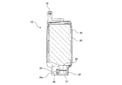
図1、図2における1は、電動車両の一例である電動自転車(電動アシスト自転車とも称される)である。この電動自転車1には、本発明の実施の形態に係るバッテリ装置の充電構造におけるバッテリ装置12が着脱自在に装着されている。
1 in FIG. 1 and FIG. 2 is an electric bicycle (also referred to as an electric assist bicycle) that is an example of an electric vehicle. A
電動自転車1は、ヘッドパイプ2a、前フォーク2b、メインパイプ2c、立パイプ2d、チェーンステー2e、シートステー2fなどからなる金属製の車体フレーム(車体)2と、前フォーク2bの下端に回転自在に取り付けられた前輪3と、チェーンステー2eの後端に回転自在に取り付けられた後輪4と、前輪3の向きを変更するハンドル5と、搭乗者が着座するサドル6と、踏力からなる人力駆動力がかけられるクランク7およびペダル8と、アシスト力(補助駆動力)を発生させる駆動源としての電動のモータ9およびこのモータ9を含めた各種の電気的制御を行う制御部などが設けられた駆動ユニット10と、ペダル8およびクランク7からの踏力に基づく人力駆動力や駆動ユニット10からの補助駆動力を後輪4に伝達する無端状駆動力伝達体としてのチェーン11と、モータ9に駆動用の電力を供給する二次電池からなるバッテリを内蔵したバッテリ装置12と、バッテリ装置12を着脱自在な状態で装着するバッテリ装着部13と、バッテリ装着部13に装着されたバッテリ装置12をロックするバッテリロック部40と、バッテリ装着部13および駆動ユニット10の左側面側などを覆うユニットカバー14と、などを備えている。
The electric bicycle 1 has a metal body frame (vehicle body) 2 composed of a
また、図11〜図18における50は、バッテリ装置12(詳しくは、バッテリ装置12のバッテリ)を充電する充電器である。バッテリ装置12を充電する際には、バッテリ装置12を電動自転車1のバッテリ装着部13から取り外し、電動自転車1とは別途に設けられている充電器50にバッテリ装置12を装着して充電可能に構成されている。充電器50の構造などについては、後で詳しく述べる。
Moreover, 50 in FIGS. 11-18 is a charger which charges the battery apparatus 12 (specifically, the battery of the battery apparatus 12). When charging the
図3〜図8などに示すように、バッテリ装置12は、略箱形状のバッテリケース16と、バッテリケース16内に内蔵されたバッテリ(複数の二次電池からなり、図6において複数の二次電池が接続されたバッテリパック全体の外形を簡略的に示す)20と、バッテリケース16の上部前面の一部に一体形成された被ロック部17と、バッテリケース16の上部に一体形成された取手部18と、バッテリケース16の上部側面における取手部18の下方箇所に設けられてバッテリ20の電気残量を表示する残量表示部19などを有している。残量表示部19には、バッテリ20の電気残量を表示するための複数の表示素子(この実施の形態では液晶表示素子)19aと、押圧操作されることで表示動作を行わせるための表示用押圧スイッチ部19bと、が設けられている。なお、本実施の形態では、バッテリケース16は、左右に2分割され、互いに係合する爪部(係合部)や凹部(被係合部)などが、バッテリ20などが内蔵された状態で組み付けられているが、これに限るものではない。
As shown in FIG. 3 to FIG. 8 and the like, the
バッテリ装置12(バッテリケース16)の底面部には、電動自転車1のバッテリ装着部13から上方に突出するように複数設けられた接続用端子32(図3、図7参照)や後述する充電器50(図11〜図18参照)に設けられた接続用端子51を挿入するための差込み孔21(図8参照)が複数形成されている。また、バッテリ装置12の内部における差込み孔21に対応する奥側の箇所には、電動自転車1のバッテリ装着部13の接続用端子32や充電器50の接続用端子51に両側から挟むなどして接続可能な接続用端子22が設けられている。また、図5、図6などに示すように、バッテリ装置12の内部には当該バッテリ装置12を制御する基板(バッテリ制御基板25)も内蔵されている。
A plurality of connection terminals 32 (see FIGS. 3 and 7) provided on the bottom surface of the battery device 12 (battery case 16) so as to protrude upward from the
図3、図8などに示すように、バッテリケース16の下部の前面と後面にはそれぞれ、前方または後方へ突出する回動部としての回動支持軸24が設けられている。なお、この実施の形態では、回動支持軸24は上下に長い長円形状(詳しくは、下端部の半円形部と上端部の半円形部とが上下に長い矩形状部で接続された形状)とされている。なお、この実施の形態では、図8などに示すように、バッテリケース16の下部が段付き形状部16bを介して上部や中央部よりも少しだけ細幅となった状態で下方に突出されており、この突出部分の前面壁部と後面壁部とからそれぞれ回動部としての回動支持軸24が前方または後方に突出する状態で設けられている。また、図3、図8などにも示すように、バッテリケース16の下部の左側面には、回動支持軸24の部分を左側方から覆うように下延部16aが一体形成されている。そして、下延部16aにより、回動支持軸24を側方から覆うことで、バッテリ装置12を電動自転車1や充電器50に装着した状態では、回動支持軸24の部分やその近傍箇所において手などを挟むことが無いように構成しているとともに、ごみが侵入し難いようにしている。また、下延部16aにより、バッテリ装置12の装着時に回動支持軸24の部分やその近傍箇所が見えないようにして、見栄えを向上させている。なお、図8における16cはバッテリ装置12の種類に応じて形成された種類判別用凹部である。
As shown in FIGS. 3, 8, and the like, a
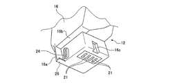
図1〜図3などに示すように、電動自転車1のバッテリ装着部13は、この実施の形態では駆動ユニット10の上方に設けられており、図3、図7などに示すように、バッテリ装着部13は、バッテリ装置12の下端部が装着される凹形状のバッテリ嵌込部31を有している。バッテリ装置12は、バッテリ嵌込部31に装着された状態で、立パイプ2dとチェーンステー2eとシートステー2fと後輪4の泥除け4aとで囲まれた空間内に配置される。また、図3、図7などに示すように、バッテリ嵌込部31の底面には、バッテリ装置12のバッテリに電気的に接続される複数の接続用端子32が設けられている。これらの接続用端子32は、バッテリ装置12の差込み孔21(図8参照)に対して挿脱自在であり、バッテリ嵌込部31内に位置している。
As shown in FIGS. 1 to 3 and the like, the
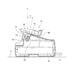
図3、図7などに示すように、バッテリ装着部13の左側前端部と左側後端部にはそれぞれ軸嵌込溝(電動自転車1のバッテリ装着部13の回動支持部)33が形成されており、バッテリ装置12の回動支持軸24が軸嵌込溝33に対して嵌脱自在かつ回動可能である。なお、図1に示すように、バッテリ装置12が電動自転車1のバッテリ装着部13に装着されている場合(バッテリ装着時とも称す)、図9に示すように、バッテリ装置12の下部がバッテリ嵌込部31に嵌まり込むとともに両方の回動支持軸24が両方の軸嵌込溝33に嵌まり込み、バッテリ装着部13の接続用端子32がバッテリ装置12の差込み孔23に差し込まれる。また、バッテリ装置12を電動自転車1のバッテリ装着部13に装着する際には、図10に示すように、バッテリ装置12を左側に傾斜させた姿勢で、バッテリ装置12の下部を電動自転車1の左側方からバッテリ嵌込部31に嵌め込むとともに回動支持軸24を軸嵌込溝33に嵌め込み、図9に示すように、回動支持軸24を中心にバッテリ装置12の上部を右側に回動させて起立させるよう構成されている。これにより、バッテリ装着部13の接続用端子32がバッテリ装置12の差込み孔23に差し込まれ、図1に示すように、バッテリ装置12がバッテリ装着部13に装着されて、バッテリ装着部13の接続用端子32がバッテリ装置12の接続用端子22と接続される。なお、図3における34はバッテリ装着部13のバッテリ嵌込部31の右側側壁に突出された種類判別用リブで、この種類判別用リブ34に対応する種類判別用凹部16cを有するバッテリ装置12、すなわち、適合するバッテリ装置12のみ、バッテリ装着部13に装着できるよう構成されている。
As shown in FIGS. 3, 7, etc., shaft insertion grooves (rotating support portions of the
図1、図2に示すように、立パイプ2dには、バッテリ装着部13に装着されたバッテリ装置12をロックする(固定する)バッテリロック部40が設けられている。バッテリロック部40は錠装置41を備えており、錠装置41の鍵(図示せず)が抜かれた状態でバッテリ装置12が装着されると、バッテリ装置12が装着姿勢にロックされるようになっている。また、装着姿勢で錠装置41に鍵が挿入されて解錠されることにより、バッテリ装置12のロック状態が解除され、バッテリ装置12を左側に回動させることで、バッテリ装置12を電動自転車1のバッテリ装着部13から取り外して充電などするために外部に持ち出すことができる。
As shown in FIGS. 1 and 2, the standing
図11〜図18における50は、バッテリ装置12のバッテリ20を充電する充電器である。また、図11は充電器50単体を示し、図11〜図16は、充電器50にバッテリ装置12を装着した状態を示している。また、この実施の形態では、充電器50とバッテリ装置12により、本実施の形態に係るバッテリ装置12の充電構造が構成されている。充電器50は内部に充電回路(充電制御回路を含む)58を有している(図15、図16において簡略的に示している)とともに、AC電源(交流電源)に接続する電源接続コード57が接続されている。
図11などに示すように、充電器50(より具体的には充電器50の外殻部を構成する充電器ケース)の上面部には、バッテリ装置12を着脱自在に装着するバッテリ装着部52が設けられている。充電器50のバッテリ装着部52には、バッテリ装置12の下端部が嵌め込まれる正面視して略凹形状のバッテリ嵌込部53と、バッテリ嵌込部53の底面部奥側箇所から斜め上方に突出されている複数の接続用端子51と、バッテリ嵌込部31の両側方箇所おいて斜め上方に突設されてバッテリ装置12の下部に設けられた段付き形状部16b(図8参照)を下方から受けることが可能な突設受部54と、バッテリ嵌込部53における両側壁面部においてそれぞれ下方に窪むように形成されて、バッテリ装置12の回転支持軸(回動部)24が嵌め込み自在な回動支持部55と、回動支持部55の前方壁部分をなす支持壁部(前側支持壁部)56などが形成されている。なお、この実施の形態では、バッテリ嵌込部53における背面部には種類判別用リブ59が突設され、この種類判別用リブ59に対応する種類判別用凹部16cを有するバッテリ装置12、すなわち、適合するバッテリ装置12のみ、バッテリ装着部52に装着して充電できるよう構成されている。
As shown in FIG. 11 and the like, a
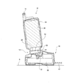
バッテリ装置12は、回転支持軸24が充電器50の回動支持部55に嵌め込まれた状態で、図11〜図15に示すように、充電器50のバッテリ装着部52に対して、充電器50の接続用端子51にバッテリ装置12の接続用端子22が接続された接続姿勢と、図17、図18に示すように、充電器50の接続用端子51からバッテリ装置12の接続用端子22が離脱された離脱姿勢とにわたって、回動自在に配設されている。つまり、充電器50のバッテリ装着部52に対して、バッテリ装置12の回転支持軸24を中心として(詳しくは回転支持軸24の下端部の半円形部(下半円部とも称す)が回動支持部55の下端の半円形溝部分に摺動した状態で、これらの半円形の中心部を中心として)回動自在に配設されている。そして、バッテリ装置12を接続姿勢から離脱姿勢側に回動させることにより、回動途中箇所で、充電器50の接続用端子51からバッテリ装置12の接続用端子22が離脱される。
As shown in FIGS. 11 to 15, the
また、これらの接続姿勢と離脱姿勢とは、何れも傾斜した姿勢とされている。すなわち、この実施の形態では、図12に示す状態を正面とすると、バッテリ装置12は、水平な面に充電器50が載せられた状態で、接続姿勢では後方に傾斜した姿勢で保持され、離脱姿勢では、前方に傾斜した姿勢で保持される。
In addition, the connection posture and the separation posture are both inclined postures. In other words, in this embodiment, assuming that the state shown in FIG. 12 is the front, the
ここで、図14に示すように、バッテリ装置12が接続姿勢である際には、充電器50のバッテリ装着部52に設けられた各接続用端子51がバッテリ装置12の差込み孔23に差し込まれ、バッテリ装置12が充電器50のバッテリ装着部52に装着されて、バッテリ装着部52の接続用端子51がバッテリ装置12の接続用端子22と接続される。また、この際、バッテリ装置12の回転支持軸(回動部)24の下半円部および右側側面部が、回動支持部55の底部および右壁面で受けられるとともに、図13に示すように、バッテリ装置12の底面部が充電器50のバッテリ嵌込部53における右寄り底面部に形成された傾斜面53a上に載せられて支持された状態とされている。また、図14に示すように、バッテリ装置12の段付き形状部16bが、充電器50の突設受部54上に載せられて支持された状態とされている。
Here, as shown in FIG. 14, when the
図15、図19などに示すように、上記構成に加えて、バッテリ装置12(バッテリケース16)の下部に設けられた各下延部16aには、バッテリ装置12の回転支持軸(回動部)24に近づく側(図15、図19などに示すように、充電器50にバッテリ装置12を装着した状態においては後方側であり、図15、図19を示す紙面では右側)に屈曲した状態で突出する回動規制部26が設けられている。この実施の形態では、回動規制部26は、下延部16aとともにバッテリケース16において一体形成されている。この回動規制部26は、図13、図15に示すように、バッテリ装置12が接続姿勢である場合には、充電器50のバッテリ装着部52における回動支持部55の前方の支持壁部(前側支持壁部とも称す)56の前面部(被当接部とも称す)から離反している。一方、図19に示すように、バッテリ装置12が離脱姿勢に位置した際には、充電器50のバッテリ装着部52における前側支持壁部56の前面部(被当接部)に当接する。これによりバッテリ装置12がさらに前側に回動することを規制して離脱姿勢に保持する。
As shown in FIGS. 15 and 19, in addition to the above-described configuration, each extending
なお、この際、図19に示すように、支持壁部(前側支持壁部)56の後面(回動支持部55が形成されている箇所)に、バッテリ装置12の回転支持軸24における前面部(図19における紙面の左側部分)も当接している。すなわち、バッテリ装置12の接続用端子22と充電器50の接続用端子51とが互いに離脱している離脱姿勢においては、バッテリ装置12が装着されている充電器50を側面視した状態で、前記2箇所(実際には、各回転支持軸24が設けられている箇所や、各回動規制部26が設けられている箇所の合計4箇所)でバッテリ装置12が充電器50に当接しており、これにより、充電器50が前側に傾斜した離脱姿勢に良好に保持される。その結果、バッテリ装置12が充電器50から脱落することが防止される。
At this time, as shown in FIG. 19, the front surface portion of the
また、上記したように、バッテリ装置12の接続姿勢と離脱姿勢とは、何れも傾斜した姿勢とされているが、この実施の形態では、図15に示すように、充電器50が載せられる載置面Sに対して直交するとともに充電器50を通る鉛直線Yに対して傾斜する前記接続姿勢の傾斜角度αが、前記離脱姿勢の傾斜角度β(図19参照)よりも大きくなるように構成されている。
Further, as described above, the connection posture and the disconnection posture of the
また、上述したように、バッテリ装置12の側面にバッテリ20の電気残量を表示する残量表示部19が設けられているが、水平な載置面Sに充電器50を載せた状態で、図16に示すように、残量表示部19が充電器50の真上から見えるように、図13、図14などに示すように、バッテリ装置12の前記接続姿勢が傾斜されて配設されている。さらに、この実施の形態では、残量表示部19がバッテリ装置12の側面(充電器50に装着した際に前面側に位置し、電動自転車1に装着した際には左側面となる箇所)において、図14に示すように、斜め後方側に傾斜させて配設されており、これにより、さらに、残量表示部19が充電器50の真上から良好に見えるようになっている。
In addition, as described above, the remaining
上記構成において、バッテリ装置12を充電する際には、電動自転車1のバッテリ装着部13からバッテリ装置12を取り外し、バッテリ装置12の回転支持軸24が、充電器50の回動支持部55に嵌め込まれるように、バッテリ装置12を手前側から下方に装着し、前記離脱姿勢とする(図17、図18参照)。そしてこの後に、回転支持軸24を中心としてバッテリ装置12の上部側を後方に回動させることで、バッテリ装置12が接続姿勢となり(図13〜図16参照)、充電器50の接続用端子51にバッテリ装置12の接続用端子22が接続され、充電が開始される。
In the above configuration, when charging the
また、バッテリ装置12の充電が終わり、バッテリ装置12を充電器50から取り外す場合には、図13〜図16に示すような接続姿勢となっているバッテリ装置12を、回転支持軸24を中心として手前側に回動させて図17、図18に示すような離脱姿勢とする。このようにバッテリ装置12を回動させることで、充電器50の接続用端子51からバッテリ装置12の接続用端子22が離脱する。そして、この後、離脱姿勢となったバッテリ装置12を斜め上方などに持ち上げることで、バッテリ装置12を充電器50から取り外すことができる。
Further, when the
このように、充電器50にバッテリ装置12を装着する際は、バッテリ装置12を充電器50のバッテリ装着部52に載せる作業を行うタイミングと、バッテリ装置12を回動させて接続用端子22、51同士を接続させるタイミングとが異なっている。これにより、バッテリ装置12の取扱者は比較的小さな力でバッテリ装置12の装着作業を行え、バッテリ装置12の取扱者に対する負担を軽減することができて、便利である。
Thus, when the
また、充電器50からバッテリ装置12を取り外す際は、接続姿勢となっているバッテリ装置12を手前側に回動させて接続用端子22、51同士を離脱させるタイミングと、この後に、バッテリ装置12を持ち上げて取り外すタイミングとが異なっている。これにより、バッテリ装置12の取扱者は、比較的小さな力でバッテリ装置12の取り外し作業を行え、バッテリ装置12の取扱者に対する負担を軽減することができて、便利である。
Further, when removing the
また、上記構成によれば、バッテリ装置12が前記接続姿勢から前記離脱姿勢に回動された際に被当接部としての充電器50の前側支持壁部56に当接して、前記離脱姿勢よりもさらに回動することを阻止するとともに前記離脱姿勢を保持する回動規制部26が設けられている。これにより、バッテリ装置12が充電器50のバッテリ装着部52から脱落することが無くなるので、脱落したバッテリ装置が床面などに当接して損傷してしまうことが無くなり、信頼性が向上する。
Further, according to the above configuration, when the
なお、上記実施の形態では、回動規制部26をバッテリ装置12の下延部16aから突出させた形状とした場合を述べたが、これに限るものではなく、例えば、充電器50の前側支持壁部の一部を前側に突出させて、バッテリ装置12が前記接続姿勢から前記離脱姿勢に回動された際に、前記突出させた部分がバッテリ装置12の下延部16aに当接するように構成してもよい。すなわち、回動規制部26は、バッテリ装置12と充電器50との何れの側に形成してもよい。
In the above-described embodiment, the case where the
また、本実施の形態では、バッテリ装置12が前記接続姿勢から前記離脱姿勢に回動された際に、充電器50の支持壁部(前側支持壁部)56の後面に、バッテリ装置12の回転支持軸24における前面部も当接し、この箇所でも当接することで、バッテリ装置12が充電器50から脱落することを良好に防止できる。これにより、比較的簡単な構成で、バッテリ装置12が充電器50から脱落することを防止できるが、この構成に限るものではない。
In the present embodiment, when the
また、バッテリ装置12の前記接続姿勢および前記離脱姿勢が充電器20に対してそれぞれ傾斜する姿勢となるように配設しているので、安定した状態で前記接続姿勢および前記離脱姿勢を保持することができる。つまり、前記接続姿勢または前記離脱姿勢が水平面に直交する鉛直な姿勢である場合には、バッテリ装置12が回動可能な不安定な姿勢となるが、本実施の形態ではこのような不具合が生じない。
Further, since the
また、バッテリ装置12の前記接続姿勢および前記離脱姿勢の何れの姿勢でも水平面に直交する鉛直線に対する傾斜角度が所定角度(例えば15度)よりも大きく構成することが好適である。これにより、充電器50を載せている箇所が若干傾斜していた場合でも、この傾斜角度が前記所定角度(例えば15度)より小さければ、前記接続姿勢および前記離脱姿勢を何れも傾斜姿勢とすることができて、何れの姿勢でもバッテリ装置12を安定して保持でき、信頼性が向上する。
In addition, it is preferable that an inclination angle with respect to a vertical line perpendicular to the horizontal plane is larger than a predetermined angle (for example, 15 degrees) in any of the connection posture and the separation posture of the
さらに、充電器50が載せられる載置面Sに対して直交するとともに充電器50を通る鉛直線に対して傾斜する接続姿勢の傾斜角度が離脱姿勢の傾斜角度よりも大きくなるように配設することで、特に安定した姿勢で維持されることが望ましい充電器50の充電時において、充電器50に装着されたバッテリ装置12の接続姿勢をより安定した状態で保持することができ、これによれば、さらに信頼性が向上する。
Furthermore, it is arranged so that the inclination angle of the connection posture that is orthogonal to the placement surface S on which the
また、上記構成によれば、バッテリ装置12の側面に設けられてバッテリ20の電気残量を表示する残量表示部19が、水平な載置面に充電器50を載せた状態で、充電器50の真上から見えるように、バッテリ装置12の前記接続姿勢が傾斜されて配設されている。これにより、充電器50を床面などに載置して充電している場合に、横方向だけでなく上方からもバッテリ20の電気残量を容易に視認することができて、便利である。また、本実施の形態では、残量表示部19がバッテリ装置12の側面において、斜め後方側に傾斜させて配設されているため、これにより、さらに、残量表示部19が充電器50の真上から良好に見えて、利便性がさらに向上する。
Moreover, according to the said structure, in the state which the remaining
また、本実施の形態では、電動自転車1のバッテリ装着部13に、バッテリ装置12の回動支持軸(回動部)24を回動自在に嵌合させて支持することができる軸嵌込溝(電動自転車1のバッテリ装着部13の回動支持部)33が設けられている。そして、バッテリ装置12が、電動自転車1のバッテリ装着部13に対して、電動自転車1のバッテリ装着部13の接続用端子32にバッテリ装置12の接続用端子22が接続された接続姿勢と、電動自転車1のバッテリ装着部13の接続用端子32からバッテリ装置12の接続用端子22が離脱された離脱姿勢とにわたって、回動自在に配設されている。
Moreover, in this Embodiment, the shaft insertion groove which can be supported by making the
この構成により、バッテリ装置12を電動自転車1のバッテリ装着部13に装着する際や電動自転車1のバッテリ装着部13から取り外す際に、バッテリ装置12を電動自転車1のバッテリ装着部13に載せたり取り出したりする作業を行うタイミングと、バッテリ装置12を回動させて電動自転車1の接続用端子32とバッテリ装置12の接続用端子22とを接続させるタイミングとが異ならせることができる。これにより、バッテリ装置12の取扱者は比較的小さな力でバッテリ装置12の電動自転車1への装着作業や取り外し作業を行え、バッテリ装置12の取扱者に対する負担を軽減することができて、便利である。
With this configuration, when the
但し、この実施の形態では、バッテリ装置12を電動自転車1のバッテリ装着部13から取り外すなどのために、バッテリ装置12を離脱姿勢にした場合でも、バッテリ装置12に設けられている回動規制部26は離脱姿勢を保持するために当接するような構成とはされていない。すなわち、バッテリ装置12を電動自転車1のバッテリ装着部13から取り外す際には、バッテリ装置12を、起立した接続姿勢から、大きく傾斜した離脱姿勢に回動させる必要があるため、本実施の形態では、離脱姿勢を保持する構造とはされていない。つまり、電動自転車1のバッテリ装着部13は比較的低い位置に設けられているため、バッテリ装置12を電動自転車1のバッテリ装着部13から取り外す際に、脱落してもバッテリ装置12が損傷することは殆ど無い。
However, in this embodiment, even when the
しかしながら、この構成に限るものではなく、図20、図21に示すように、バッテリ装置12を離脱姿勢にした場合に、離脱姿勢を保持するために、回動規制部26が当接する被当接部27をバッテリ装着部13の一部に設けてもよい。これにより、バッテリ装置12を離脱姿勢にした場合に、離脱姿勢を保持することが可能となり、信頼性を向上させることができる。
However, the present invention is not limited to this configuration, and as shown in FIGS. 20 and 21, when the
なお、上記実施の形態においては、電動車両が電動自転車1である場合を述べ、この場合の電動自転車1としては、踏力による人力駆動力に対応してモータによる補助駆動力を付加するものであると好適である。しかしながら、踏力によらず、モータによる駆動力だけで自走可能な電動自転車のバッテリ装置を充電する充電構造についても上記構成を適用可能である。さらに、電動車両としては、電動自転車以外でもよく、電動2輪車、電気自動車、電動芝刈り機、電動車いすなど、各種の電動車両に用いられるバッテリ装置を充電する充電構造に適用することも可能である。 In the above-described embodiment, the case where the electric vehicle is the electric bicycle 1 is described. In this case, the electric bicycle 1 adds an auxiliary driving force by a motor corresponding to a human driving force by a pedaling force. It is preferable. However, the above configuration can also be applied to a charging structure that charges a battery device of an electric bicycle that can be self-propelled only by the driving force of a motor, regardless of the pedaling force. Furthermore, the electric vehicle may be other than an electric bicycle, and can be applied to a charging structure for charging a battery device used in various electric vehicles such as an electric motorcycle, an electric vehicle, an electric lawn mower, and an electric wheelchair. It is.
1 電動自転車
2 車体フレーム(車体)
9 モータ
10 駆動ユニット
12 バッテリ装置
13 バッテリ装着部(電動自転車のバッテリ装着部)
19 残量表示部
20 バッテリ
22 接続用端子(バッテリ装置の接続用端子)
24 回動支持軸(回動部)
26 回動規制部
32 接続用端子(電動自転車の接続用端子)
33 軸嵌込溝
50 充電器
51 接続用端子(充電器の接続用端子)
52 バッテリ装着部(充電器のバッテリ装着部)
55 回動支持部
56 支持壁部(前側支持壁部)
1
9 motor 10
19 Remaining
24 Rotating support shaft (Rotating part)
26
33
52 Battery mounting part (battery mounting part of the charger)
55 Rotating
Claims (6)
前記バッテリ装置と前記充電器とにそれぞれ接続用端子が設けられているバッテリ装置の充電構造であって、
前記充電器のバッテリ装着部に、前記バッテリ装置を回動自在に支持する回動支持部が設けられ、
前記バッテリ装置に、前記回動支持部に嵌合可能な回動部が設けられ、
前記バッテリ装置が、前記充電器のバッテリ装着部に対して、前記充電器の接続用端子に前記バッテリ装置の接続用端子が接続された接続姿勢と、前記充電器の接続用端子から前記バッテリ装置の接続用端子が離脱された離脱姿勢とにわたって、回動自在に配設され、
前記バッテリ装置が前記接続姿勢から前記離脱姿勢に回動された際に被当接部に当接して、前記離脱姿勢よりもさらに回動することを阻止するとともに前記離脱姿勢を保持する回動規制部が設けられていることを特徴とするバッテリ装置の充電構造。 A battery device that is detachably attached to the electric vehicle and has a built-in battery, and a charger that has a battery mounting portion and charges the battery of the battery device;
A battery device charging structure in which connection terminals are provided on the battery device and the charger, respectively.
The battery mounting portion of the charger is provided with a rotation support portion that rotatably supports the battery device,
The battery device is provided with a rotation portion that can be fitted to the rotation support portion,
The battery device has a connection posture in which a connection terminal of the battery device is connected to a connection terminal of the charger with respect to a battery mounting portion of the charger, and the battery device from the connection terminal of the charger. The connecting terminal is disposed so as to be freely rotatable over the disengagement posture from which the connection terminal is disengaged,
When the battery device is rotated from the connection posture to the disengagement posture, the battery device abuts against the contacted portion and prevents further rotation than the disengagement posture and holds the disengagement posture. A charging structure for a battery device, characterized in that a part is provided.
水平な載置面に前記充電器を載せた状態で、前記残量表示部が前記充電器の真上から見えるように、前記バッテリ装置の前記接続姿勢が傾斜されて配設されていることを特徴とする請求項2に記載のバッテリ装置の充電構造。 A remaining amount display part for displaying the remaining amount of electricity in the battery is provided on the side of the battery device,
In a state where the charger is mounted on a horizontal mounting surface, the connection posture of the battery device is inclined and arranged so that the remaining amount display unit can be seen from directly above the charger. The charging structure of the battery device according to claim 2, wherein
前記バッテリ装置と前記バッテリ装着部とにそれぞれ接続用端子が設けられている電動車両であって、
前記バッテリ装着部に、前記バッテリ装置を回動自在に支持する回動支持部が設けられ、
前記バッテリ装置に、前記回動支持部に嵌合可能な回動部が設けられ、
前記バッテリ装置が、前記バッテリ装着部に対して、前記バッテリ装着部の接続用端子に前記バッテリ装置の接続用端子が接続された接続姿勢と、前記バッテリ装着部の接続用端子から前記バッテリ装置の接続用端子が離脱された離脱姿勢とにわたって、回動自在に配設され、
前記バッテリ装置が前記接続姿勢から前記離脱姿勢に回動された際に被当接部に当接して、前記離脱姿勢よりもさらに回動することを阻止するとともに前記離脱姿勢を保持する回動規制部が設けられていることを特徴とする電動車両。 The battery mounting part has a detachable battery device,
An electric vehicle in which connection terminals are provided on each of the battery device and the battery mounting portion,
The battery mounting portion is provided with a rotation support portion that rotatably supports the battery device,
The battery device is provided with a rotation portion that can be fitted to the rotation support portion,
The battery device has a connection posture in which the connection terminal of the battery device is connected to a connection terminal of the battery mounting portion with respect to the battery mounting portion, and a connection posture of the battery device from the connection terminal of the battery mounting portion. The connection terminal is disposed so as to be freely rotatable over the disengagement posture in which the connection terminal is disengaged,
When the battery device is rotated from the connection posture to the disengagement posture, the battery device abuts against the contacted portion and prevents further rotation than the disengagement posture and holds the disengagement posture. The electric vehicle characterized by the above-mentioned.
Priority Applications (1)
| Application Number | Priority Date | Filing Date | Title |
|---|---|---|---|
| JP2015197272A JP6573073B2 (en) | 2015-10-05 | 2015-10-05 | Battery device charging structure and electric vehicle |
Applications Claiming Priority (1)
| Application Number | Priority Date | Filing Date | Title |
|---|---|---|---|
| JP2015197272A JP6573073B2 (en) | 2015-10-05 | 2015-10-05 | Battery device charging structure and electric vehicle |
Publications (2)
| Publication Number | Publication Date |
|---|---|
| JP2017073838A JP2017073838A (en) | 2017-04-13 |
| JP6573073B2 true JP6573073B2 (en) | 2019-09-11 |
Family
ID=58537661
Family Applications (1)
| Application Number | Title | Priority Date | Filing Date |
|---|---|---|---|
| JP2015197272A Active JP6573073B2 (en) | 2015-10-05 | 2015-10-05 | Battery device charging structure and electric vehicle |
Country Status (1)
| Country | Link |
|---|---|
| JP (1) | JP6573073B2 (en) |
Families Citing this family (6)
| Publication number | Priority date | Publication date | Assignee | Title |
|---|---|---|---|---|
| JP6286084B1 (en) * | 2017-03-24 | 2018-02-28 | 本田技研工業株式会社 | Containment device |
| US11309611B2 (en) | 2017-10-10 | 2022-04-19 | The Furukawa Battery Co., Ltd. | Battery mounting unit, electric device, and power supply unit |
| JP6827436B2 (en) * | 2018-03-12 | 2021-02-10 | ヤンマーパワーテクノロジー株式会社 | Crawler traveling device |
| JP7070048B2 (en) * | 2018-04-26 | 2022-05-18 | ブラザー工業株式会社 | Charger |
| JPWO2021049622A1 (en) * | 2019-09-11 | 2021-03-18 | ||
| CN110641610B (en) * | 2019-10-03 | 2020-12-01 | 林雅娟 | Manual installation automatic butt joint system for sharing moped battery |
Family Cites Families (9)
| Publication number | Priority date | Publication date | Assignee | Title |
|---|---|---|---|---|
| JPH1027629A (en) * | 1996-07-10 | 1998-01-27 | Honda Motor Co Ltd | Charge/discharge structure of battery for electric motor assisted bicycle |
| JP3257434B2 (en) * | 1997-03-07 | 2002-02-18 | 松下電器産業株式会社 | Electric bicycle and battery case mounting device for electric bicycle etc. |
| JP2000253592A (en) * | 1999-02-26 | 2000-09-14 | Sanyo Electric Co Ltd | Charger |
| JP3510170B2 (en) * | 2000-02-08 | 2004-03-22 | 松下電器産業株式会社 | Electric bicycle battery case mounting structure and electric bicycle |
| JP4836721B2 (en) * | 2006-09-08 | 2011-12-14 | パナソニック株式会社 | Electric vehicle |
| US8413947B2 (en) * | 2010-11-12 | 2013-04-09 | Joy Industrial Co., Ltd. | Positioning device for battery box |
| JP5838368B2 (en) * | 2011-11-14 | 2016-01-06 | パナソニックIpマネジメント株式会社 | Battery lock structure for electric vehicles |
| JP5894814B2 (en) * | 2012-02-20 | 2016-03-30 | 本田技研工業株式会社 | Electric vehicle power supply |
| CN202783627U (en) * | 2012-09-07 | 2013-03-13 | 重庆望江摩托车制造有限公司 | Electric bicycle |
-
2015
- 2015-10-05 JP JP2015197272A patent/JP6573073B2/en active Active
Also Published As
| Publication number | Publication date |
|---|---|
| JP2017073838A (en) | 2017-04-13 |
Similar Documents
| Publication | Publication Date | Title |
|---|---|---|
| JP6573073B2 (en) | Battery device charging structure and electric vehicle | |
| JP5355796B2 (en) | Scooter type electric vehicle | |
| JP5894814B2 (en) | Electric vehicle power supply | |
| JP5680431B2 (en) | Motorcycle | |
| JP5999914B2 (en) | Electric vehicle power supply | |
| KR101590738B1 (en) | Electrical component layout structure for electrically powered bicycle | |
| EP2799320B1 (en) | Electric straddled vehicle | |
| JP6650601B2 (en) | Battery device mounting structure and electric bicycle | |
| US20130257374A1 (en) | Charging device for electrically driven vehicle, and vehicle incorporating the same | |
| EP2626231A2 (en) | Power supply device for electric vehicle | |
| JPH11105759A (en) | Motor assisted bicycle | |
| JP6903082B2 (en) | Electric motorcycle | |
| JP2014141166A (en) | Power source device for bicycle, and bicycle | |
| JP7118182B2 (en) | saddle type electric vehicle | |
| JP2013132169A (en) | Portable charger | |
| JP5828006B2 (en) | Straddle-type electric vehicle | |
| JP5964323B2 (en) | Straddle-type electric vehicle | |
| WO2019065495A1 (en) | Battery mounting/demounting structure for saddled vehicles | |
| JP3945678B2 (en) | Battery storage device for battery-assisted bicycle and battery-assisted bicycle | |
| JP6199146B2 (en) | Electric assist bicycle | |
| JP2016104606A (en) | Saddle-riding type electric vehicle | |
| JP2013129342A (en) | Saddle riding type electric vehicle | |
| JP2003235905A (en) | Electric vehicle | |
| JP2024052490A (en) | Electric two-wheeler | |
| CN110104114B (en) | Mounting structure of electric vehicle battery box |
Legal Events
| Date | Code | Title | Description |
|---|---|---|---|
| A621 | Written request for application examination |
Free format text: JAPANESE INTERMEDIATE CODE: A621 Effective date: 20180919 |
|
| A977 | Report on retrieval |
Free format text: JAPANESE INTERMEDIATE CODE: A971007 Effective date: 20190614 |
|
| TRDD | Decision of grant or rejection written | ||
| A01 | Written decision to grant a patent or to grant a registration (utility model) |
Free format text: JAPANESE INTERMEDIATE CODE: A01 Effective date: 20190702 |
|
| A61 | First payment of annual fees (during grant procedure) |
Free format text: JAPANESE INTERMEDIATE CODE: A61 Effective date: 20190730 |
|
| R151 | Written notification of patent or utility model registration |
Ref document number: 6573073 Country of ref document: JP Free format text: JAPANESE INTERMEDIATE CODE: R151 |