WO2021193979A1 - Windshield - Google Patents
Windshield Download PDFInfo
- Publication number
- WO2021193979A1 WO2021193979A1 PCT/JP2021/013429 JP2021013429W WO2021193979A1 WO 2021193979 A1 WO2021193979 A1 WO 2021193979A1 JP 2021013429 W JP2021013429 W JP 2021013429W WO 2021193979 A1 WO2021193979 A1 WO 2021193979A1
- Authority
- WO
- WIPO (PCT)
- Prior art keywords
- glass plate
- windshield
- compression
- principal stress
- vehicle
- Prior art date
Links
- 239000011521 glass Substances 0.000 claims abstract description 223
- 230000006835 compression Effects 0.000 claims abstract description 43
- 238000007906 compression Methods 0.000 claims abstract description 43
- 238000000034 method Methods 0.000 claims description 30
- 239000011229 interlayer Substances 0.000 claims description 23
- 238000003825 pressing Methods 0.000 claims description 13
- 239000005340 laminated glass Substances 0.000 description 44
- 239000010410 layer Substances 0.000 description 32
- 239000012792 core layer Substances 0.000 description 16
- 238000012360 testing method Methods 0.000 description 11
- 238000009826 distribution Methods 0.000 description 10
- 229920005989 resin Polymers 0.000 description 9
- 239000011347 resin Substances 0.000 description 9
- UQSXHKLRYXJYBZ-UHFFFAOYSA-N Iron oxide Chemical compound [Fe]=O UQSXHKLRYXJYBZ-UHFFFAOYSA-N 0.000 description 8
- 239000004575 stone Substances 0.000 description 8
- 230000000052 comparative effect Effects 0.000 description 7
- XEEYBQQBJWHFJM-UHFFFAOYSA-N iron Substances [Fe] XEEYBQQBJWHFJM-UHFFFAOYSA-N 0.000 description 7
- 230000006378 damage Effects 0.000 description 6
- 238000004519 manufacturing process Methods 0.000 description 6
- 239000000919 ceramic Substances 0.000 description 5
- 238000010030 laminating Methods 0.000 description 5
- 239000000463 material Substances 0.000 description 4
- 239000000203 mixture Substances 0.000 description 4
- 229920002037 poly(vinyl butyral) polymer Polymers 0.000 description 4
- 238000010791 quenching Methods 0.000 description 4
- 230000000171 quenching effect Effects 0.000 description 4
- 238000004088 simulation Methods 0.000 description 4
- 229910018072 Al 2 O 3 Inorganic materials 0.000 description 3
- 229910004298 SiO 2 Inorganic materials 0.000 description 3
- 238000005336 cracking Methods 0.000 description 3
- 238000002474 experimental method Methods 0.000 description 3
- 238000012986 modification Methods 0.000 description 3
- 230000004048 modification Effects 0.000 description 3
- DHKHKXVYLBGOIT-UHFFFAOYSA-N 1,1-Diethoxyethane Chemical compound CCOC(C)OCC DHKHKXVYLBGOIT-UHFFFAOYSA-N 0.000 description 2
- 206010019196 Head injury Diseases 0.000 description 2
- 229910010413 TiO 2 Inorganic materials 0.000 description 2
- 239000011354 acetal resin Substances 0.000 description 2
- 230000007423 decrease Effects 0.000 description 2
- 238000001035 drying Methods 0.000 description 2
- 239000005038 ethylene vinyl acetate Substances 0.000 description 2
- 238000010304 firing Methods 0.000 description 2
- 239000005357 flat glass Substances 0.000 description 2
- 238000010438 heat treatment Methods 0.000 description 2
- AMWRITDGCCNYAT-UHFFFAOYSA-L hydroxy(oxo)manganese;manganese Chemical compound [Mn].O[Mn]=O.O[Mn]=O AMWRITDGCCNYAT-UHFFFAOYSA-L 0.000 description 2
- 238000005259 measurement Methods 0.000 description 2
- 238000000465 moulding Methods 0.000 description 2
- 230000035515 penetration Effects 0.000 description 2
- 230000002093 peripheral effect Effects 0.000 description 2
- 229920001200 poly(ethylene-vinyl acetate) Polymers 0.000 description 2
- 229920006324 polyoxymethylene Polymers 0.000 description 2
- 238000007650 screen-printing Methods 0.000 description 2
- 239000002356 single layer Substances 0.000 description 2
- 239000005361 soda-lime glass Substances 0.000 description 2
- 238000002834 transmittance Methods 0.000 description 2
- 229920002554 vinyl polymer Polymers 0.000 description 2
- QPLDLSVMHZLSFG-UHFFFAOYSA-N Copper oxide Chemical compound [Cu]=O QPLDLSVMHZLSFG-UHFFFAOYSA-N 0.000 description 1
- 239000005751 Copper oxide Substances 0.000 description 1
- WGLPBDUCMAPZCE-UHFFFAOYSA-N Trioxochromium Chemical compound O=[Cr](=O)=O WGLPBDUCMAPZCE-UHFFFAOYSA-N 0.000 description 1
- 238000010521 absorption reaction Methods 0.000 description 1
- 239000000654 additive Substances 0.000 description 1
- 229910052783 alkali metal Inorganic materials 0.000 description 1
- 150000001340 alkali metals Chemical group 0.000 description 1
- 238000013459 approach Methods 0.000 description 1
- 238000005452 bending Methods 0.000 description 1
- 229910052797 bismuth Inorganic materials 0.000 description 1
- JCXGWMGPZLAOME-UHFFFAOYSA-N bismuth atom Chemical compound [Bi] JCXGWMGPZLAOME-UHFFFAOYSA-N 0.000 description 1
- DQXBYHZEEUGOBF-UHFFFAOYSA-N but-3-enoic acid;ethene Chemical compound C=C.OC(=O)CC=C DQXBYHZEEUGOBF-UHFFFAOYSA-N 0.000 description 1
- 229910000423 chromium oxide Inorganic materials 0.000 description 1
- 238000001816 cooling Methods 0.000 description 1
- 229910000431 copper oxide Inorganic materials 0.000 description 1
- 238000001125 extrusion Methods 0.000 description 1
- 238000002347 injection Methods 0.000 description 1
- 239000007924 injection Substances 0.000 description 1
- 238000009413 insulation Methods 0.000 description 1
- 238000003475 lamination Methods 0.000 description 1
- 239000012528 membrane Substances 0.000 description 1
- 230000003287 optical effect Effects 0.000 description 1
- 239000004014 plasticizer Substances 0.000 description 1
- 229920000728 polyester Polymers 0.000 description 1
- 238000007639 printing Methods 0.000 description 1
- 238000012546 transfer Methods 0.000 description 1
- 238000005303 weighing Methods 0.000 description 1
- 239000013585 weight reducing agent Substances 0.000 description 1
- ZFZQOKHLXAVJIF-UHFFFAOYSA-N zinc;boric acid;dihydroxy(dioxido)silane Chemical compound [Zn+2].OB(O)O.O[Si](O)([O-])[O-] ZFZQOKHLXAVJIF-UHFFFAOYSA-N 0.000 description 1
Images


Classifications
-
- B—PERFORMING OPERATIONS; TRANSPORTING
- B60—VEHICLES IN GENERAL
- B60J—WINDOWS, WINDSCREENS, NON-FIXED ROOFS, DOORS, OR SIMILAR DEVICES FOR VEHICLES; REMOVABLE EXTERNAL PROTECTIVE COVERINGS SPECIALLY ADAPTED FOR VEHICLES
- B60J1/00—Windows; Windscreens; Accessories therefor
-
- C—CHEMISTRY; METALLURGY
- C03—GLASS; MINERAL OR SLAG WOOL
- C03B—MANUFACTURE, SHAPING, OR SUPPLEMENTARY PROCESSES
- C03B23/00—Re-forming shaped glass
- C03B23/02—Re-forming glass sheets
- C03B23/023—Re-forming glass sheets by bending
- C03B23/025—Re-forming glass sheets by bending by gravity
- C03B23/0252—Re-forming glass sheets by bending by gravity by gravity only, e.g. sagging
-
- B—PERFORMING OPERATIONS; TRANSPORTING
- B32—LAYERED PRODUCTS
- B32B—LAYERED PRODUCTS, i.e. PRODUCTS BUILT-UP OF STRATA OF FLAT OR NON-FLAT, e.g. CELLULAR OR HONEYCOMB, FORM
- B32B1/00—Layered products having a general shape other than plane
-
- B—PERFORMING OPERATIONS; TRANSPORTING
- B32—LAYERED PRODUCTS
- B32B—LAYERED PRODUCTS, i.e. PRODUCTS BUILT-UP OF STRATA OF FLAT OR NON-FLAT, e.g. CELLULAR OR HONEYCOMB, FORM
- B32B17/00—Layered products essentially comprising sheet glass, or glass, slag, or like fibres
- B32B17/06—Layered products essentially comprising sheet glass, or glass, slag, or like fibres comprising glass as the main or only constituent of a layer, next to another layer of a specific material
- B32B17/10—Layered products essentially comprising sheet glass, or glass, slag, or like fibres comprising glass as the main or only constituent of a layer, next to another layer of a specific material of synthetic resin
- B32B17/10005—Layered products essentially comprising sheet glass, or glass, slag, or like fibres comprising glass as the main or only constituent of a layer, next to another layer of a specific material of synthetic resin laminated safety glass or glazing
- B32B17/10009—Layered products essentially comprising sheet glass, or glass, slag, or like fibres comprising glass as the main or only constituent of a layer, next to another layer of a specific material of synthetic resin laminated safety glass or glazing characterized by the number, the constitution or treatment of glass sheets
- B32B17/10036—Layered products essentially comprising sheet glass, or glass, slag, or like fibres comprising glass as the main or only constituent of a layer, next to another layer of a specific material of synthetic resin laminated safety glass or glazing characterized by the number, the constitution or treatment of glass sheets comprising two outer glass sheets
-
- B—PERFORMING OPERATIONS; TRANSPORTING
- B32—LAYERED PRODUCTS
- B32B—LAYERED PRODUCTS, i.e. PRODUCTS BUILT-UP OF STRATA OF FLAT OR NON-FLAT, e.g. CELLULAR OR HONEYCOMB, FORM
- B32B17/00—Layered products essentially comprising sheet glass, or glass, slag, or like fibres
- B32B17/06—Layered products essentially comprising sheet glass, or glass, slag, or like fibres comprising glass as the main or only constituent of a layer, next to another layer of a specific material
- B32B17/10—Layered products essentially comprising sheet glass, or glass, slag, or like fibres comprising glass as the main or only constituent of a layer, next to another layer of a specific material of synthetic resin
- B32B17/10005—Layered products essentially comprising sheet glass, or glass, slag, or like fibres comprising glass as the main or only constituent of a layer, next to another layer of a specific material of synthetic resin laminated safety glass or glazing
- B32B17/10009—Layered products essentially comprising sheet glass, or glass, slag, or like fibres comprising glass as the main or only constituent of a layer, next to another layer of a specific material of synthetic resin laminated safety glass or glazing characterized by the number, the constitution or treatment of glass sheets
- B32B17/10064—Layered products essentially comprising sheet glass, or glass, slag, or like fibres comprising glass as the main or only constituent of a layer, next to another layer of a specific material of synthetic resin laminated safety glass or glazing characterized by the number, the constitution or treatment of glass sheets comprising at least two glass sheets, only one of which being an outer layer
-
- B—PERFORMING OPERATIONS; TRANSPORTING
- B32—LAYERED PRODUCTS
- B32B—LAYERED PRODUCTS, i.e. PRODUCTS BUILT-UP OF STRATA OF FLAT OR NON-FLAT, e.g. CELLULAR OR HONEYCOMB, FORM
- B32B17/00—Layered products essentially comprising sheet glass, or glass, slag, or like fibres
- B32B17/06—Layered products essentially comprising sheet glass, or glass, slag, or like fibres comprising glass as the main or only constituent of a layer, next to another layer of a specific material
- B32B17/10—Layered products essentially comprising sheet glass, or glass, slag, or like fibres comprising glass as the main or only constituent of a layer, next to another layer of a specific material of synthetic resin
- B32B17/10005—Layered products essentially comprising sheet glass, or glass, slag, or like fibres comprising glass as the main or only constituent of a layer, next to another layer of a specific material of synthetic resin laminated safety glass or glazing
- B32B17/10009—Layered products essentially comprising sheet glass, or glass, slag, or like fibres comprising glass as the main or only constituent of a layer, next to another layer of a specific material of synthetic resin laminated safety glass or glazing characterized by the number, the constitution or treatment of glass sheets
- B32B17/10082—Properties of the bulk of a glass sheet
- B32B17/10091—Properties of the bulk of a glass sheet thermally hardened
-
- B—PERFORMING OPERATIONS; TRANSPORTING
- B32—LAYERED PRODUCTS
- B32B—LAYERED PRODUCTS, i.e. PRODUCTS BUILT-UP OF STRATA OF FLAT OR NON-FLAT, e.g. CELLULAR OR HONEYCOMB, FORM
- B32B17/00—Layered products essentially comprising sheet glass, or glass, slag, or like fibres
- B32B17/06—Layered products essentially comprising sheet glass, or glass, slag, or like fibres comprising glass as the main or only constituent of a layer, next to another layer of a specific material
- B32B17/10—Layered products essentially comprising sheet glass, or glass, slag, or like fibres comprising glass as the main or only constituent of a layer, next to another layer of a specific material of synthetic resin
- B32B17/10005—Layered products essentially comprising sheet glass, or glass, slag, or like fibres comprising glass as the main or only constituent of a layer, next to another layer of a specific material of synthetic resin laminated safety glass or glazing
- B32B17/10009—Layered products essentially comprising sheet glass, or glass, slag, or like fibres comprising glass as the main or only constituent of a layer, next to another layer of a specific material of synthetic resin laminated safety glass or glazing characterized by the number, the constitution or treatment of glass sheets
- B32B17/10128—Treatment of at least one glass sheet
- B32B17/10137—Chemical strengthening
-
- B—PERFORMING OPERATIONS; TRANSPORTING
- B32—LAYERED PRODUCTS
- B32B—LAYERED PRODUCTS, i.e. PRODUCTS BUILT-UP OF STRATA OF FLAT OR NON-FLAT, e.g. CELLULAR OR HONEYCOMB, FORM
- B32B17/00—Layered products essentially comprising sheet glass, or glass, slag, or like fibres
- B32B17/06—Layered products essentially comprising sheet glass, or glass, slag, or like fibres comprising glass as the main or only constituent of a layer, next to another layer of a specific material
- B32B17/10—Layered products essentially comprising sheet glass, or glass, slag, or like fibres comprising glass as the main or only constituent of a layer, next to another layer of a specific material of synthetic resin
- B32B17/10005—Layered products essentially comprising sheet glass, or glass, slag, or like fibres comprising glass as the main or only constituent of a layer, next to another layer of a specific material of synthetic resin laminated safety glass or glazing
- B32B17/10165—Functional features of the laminated safety glass or glazing
- B32B17/10339—Specific parts of the laminated safety glass or glazing being colored or tinted
- B32B17/10348—Specific parts of the laminated safety glass or glazing being colored or tinted comprising an obscuration band
-
- B—PERFORMING OPERATIONS; TRANSPORTING
- B32—LAYERED PRODUCTS
- B32B—LAYERED PRODUCTS, i.e. PRODUCTS BUILT-UP OF STRATA OF FLAT OR NON-FLAT, e.g. CELLULAR OR HONEYCOMB, FORM
- B32B17/00—Layered products essentially comprising sheet glass, or glass, slag, or like fibres
- B32B17/06—Layered products essentially comprising sheet glass, or glass, slag, or like fibres comprising glass as the main or only constituent of a layer, next to another layer of a specific material
- B32B17/10—Layered products essentially comprising sheet glass, or glass, slag, or like fibres comprising glass as the main or only constituent of a layer, next to another layer of a specific material of synthetic resin
- B32B17/10005—Layered products essentially comprising sheet glass, or glass, slag, or like fibres comprising glass as the main or only constituent of a layer, next to another layer of a specific material of synthetic resin laminated safety glass or glazing
- B32B17/1055—Layered products essentially comprising sheet glass, or glass, slag, or like fibres comprising glass as the main or only constituent of a layer, next to another layer of a specific material of synthetic resin laminated safety glass or glazing characterized by the resin layer, i.e. interlayer
- B32B17/10651—Layered products essentially comprising sheet glass, or glass, slag, or like fibres comprising glass as the main or only constituent of a layer, next to another layer of a specific material of synthetic resin laminated safety glass or glazing characterized by the resin layer, i.e. interlayer comprising colorants, e.g. dyes or pigments
- B32B17/1066—Layered products essentially comprising sheet glass, or glass, slag, or like fibres comprising glass as the main or only constituent of a layer, next to another layer of a specific material of synthetic resin laminated safety glass or glazing characterized by the resin layer, i.e. interlayer comprising colorants, e.g. dyes or pigments imparting a tint in certain regions only, i.e. shade band
-
- B—PERFORMING OPERATIONS; TRANSPORTING
- B32—LAYERED PRODUCTS
- B32B—LAYERED PRODUCTS, i.e. PRODUCTS BUILT-UP OF STRATA OF FLAT OR NON-FLAT, e.g. CELLULAR OR HONEYCOMB, FORM
- B32B17/00—Layered products essentially comprising sheet glass, or glass, slag, or like fibres
- B32B17/06—Layered products essentially comprising sheet glass, or glass, slag, or like fibres comprising glass as the main or only constituent of a layer, next to another layer of a specific material
- B32B17/10—Layered products essentially comprising sheet glass, or glass, slag, or like fibres comprising glass as the main or only constituent of a layer, next to another layer of a specific material of synthetic resin
- B32B17/10005—Layered products essentially comprising sheet glass, or glass, slag, or like fibres comprising glass as the main or only constituent of a layer, next to another layer of a specific material of synthetic resin laminated safety glass or glazing
- B32B17/1055—Layered products essentially comprising sheet glass, or glass, slag, or like fibres comprising glass as the main or only constituent of a layer, next to another layer of a specific material of synthetic resin laminated safety glass or glazing characterized by the resin layer, i.e. interlayer
- B32B17/10761—Layered products essentially comprising sheet glass, or glass, slag, or like fibres comprising glass as the main or only constituent of a layer, next to another layer of a specific material of synthetic resin laminated safety glass or glazing characterized by the resin layer, i.e. interlayer containing vinyl acetal
-
- B—PERFORMING OPERATIONS; TRANSPORTING
- B32—LAYERED PRODUCTS
- B32B—LAYERED PRODUCTS, i.e. PRODUCTS BUILT-UP OF STRATA OF FLAT OR NON-FLAT, e.g. CELLULAR OR HONEYCOMB, FORM
- B32B17/00—Layered products essentially comprising sheet glass, or glass, slag, or like fibres
- B32B17/06—Layered products essentially comprising sheet glass, or glass, slag, or like fibres comprising glass as the main or only constituent of a layer, next to another layer of a specific material
- B32B17/10—Layered products essentially comprising sheet glass, or glass, slag, or like fibres comprising glass as the main or only constituent of a layer, next to another layer of a specific material of synthetic resin
- B32B17/10005—Layered products essentially comprising sheet glass, or glass, slag, or like fibres comprising glass as the main or only constituent of a layer, next to another layer of a specific material of synthetic resin laminated safety glass or glazing
- B32B17/1055—Layered products essentially comprising sheet glass, or glass, slag, or like fibres comprising glass as the main or only constituent of a layer, next to another layer of a specific material of synthetic resin laminated safety glass or glazing characterized by the resin layer, i.e. interlayer
- B32B17/10788—Layered products essentially comprising sheet glass, or glass, slag, or like fibres comprising glass as the main or only constituent of a layer, next to another layer of a specific material of synthetic resin laminated safety glass or glazing characterized by the resin layer, i.e. interlayer containing ethylene vinylacetate
-
- B—PERFORMING OPERATIONS; TRANSPORTING
- B32—LAYERED PRODUCTS
- B32B—LAYERED PRODUCTS, i.e. PRODUCTS BUILT-UP OF STRATA OF FLAT OR NON-FLAT, e.g. CELLULAR OR HONEYCOMB, FORM
- B32B17/00—Layered products essentially comprising sheet glass, or glass, slag, or like fibres
- B32B17/06—Layered products essentially comprising sheet glass, or glass, slag, or like fibres comprising glass as the main or only constituent of a layer, next to another layer of a specific material
- B32B17/10—Layered products essentially comprising sheet glass, or glass, slag, or like fibres comprising glass as the main or only constituent of a layer, next to another layer of a specific material of synthetic resin
- B32B17/10005—Layered products essentially comprising sheet glass, or glass, slag, or like fibres comprising glass as the main or only constituent of a layer, next to another layer of a specific material of synthetic resin laminated safety glass or glazing
- B32B17/10807—Making laminated safety glass or glazing; Apparatus therefor
- B32B17/10816—Making laminated safety glass or glazing; Apparatus therefor by pressing
-
- B—PERFORMING OPERATIONS; TRANSPORTING
- B32—LAYERED PRODUCTS
- B32B—LAYERED PRODUCTS, i.e. PRODUCTS BUILT-UP OF STRATA OF FLAT OR NON-FLAT, e.g. CELLULAR OR HONEYCOMB, FORM
- B32B7/00—Layered products characterised by the relation between layers; Layered products characterised by the relative orientation of features between layers, or by the relative values of a measurable parameter between layers, i.e. products comprising layers having different physical, chemical or physicochemical properties; Layered products characterised by the interconnection of layers
- B32B7/02—Physical, chemical or physicochemical properties
- B32B7/022—Mechanical properties
-
- C—CHEMISTRY; METALLURGY
- C03—GLASS; MINERAL OR SLAG WOOL
- C03B—MANUFACTURE, SHAPING, OR SUPPLEMENTARY PROCESSES
- C03B23/00—Re-forming shaped glass
- C03B23/02—Re-forming glass sheets
- C03B23/023—Re-forming glass sheets by bending
- C03B23/03—Re-forming glass sheets by bending by press-bending between shaping moulds
-
- C—CHEMISTRY; METALLURGY
- C03—GLASS; MINERAL OR SLAG WOOL
- C03B—MANUFACTURE, SHAPING, OR SUPPLEMENTARY PROCESSES
- C03B25/00—Annealing glass products
- C03B25/02—Annealing glass products in a discontinuous way
- C03B25/025—Glass sheets
-
- C—CHEMISTRY; METALLURGY
- C03—GLASS; MINERAL OR SLAG WOOL
- C03B—MANUFACTURE, SHAPING, OR SUPPLEMENTARY PROCESSES
- C03B25/00—Annealing glass products
- C03B25/04—Annealing glass products in a continuous way
- C03B25/06—Annealing glass products in a continuous way with horizontal displacement of the glass products
- C03B25/08—Annealing glass products in a continuous way with horizontal displacement of the glass products of glass sheets
-
- C—CHEMISTRY; METALLURGY
- C03—GLASS; MINERAL OR SLAG WOOL
- C03B—MANUFACTURE, SHAPING, OR SUPPLEMENTARY PROCESSES
- C03B27/00—Tempering or quenching glass products
- C03B27/04—Tempering or quenching glass products using gas
- C03B27/0413—Stresses, e.g. patterns, values or formulae for flat or bent glass sheets
-
- C—CHEMISTRY; METALLURGY
- C03—GLASS; MINERAL OR SLAG WOOL
- C03B—MANUFACTURE, SHAPING, OR SUPPLEMENTARY PROCESSES
- C03B27/00—Tempering or quenching glass products
- C03B27/04—Tempering or quenching glass products using gas
- C03B27/044—Tempering or quenching glass products using gas for flat or bent glass sheets being in a horizontal position
- C03B27/0442—Tempering or quenching glass products using gas for flat or bent glass sheets being in a horizontal position for bent glass sheets
-
- C—CHEMISTRY; METALLURGY
- C03—GLASS; MINERAL OR SLAG WOOL
- C03C—CHEMICAL COMPOSITION OF GLASSES, GLAZES OR VITREOUS ENAMELS; SURFACE TREATMENT OF GLASS; SURFACE TREATMENT OF FIBRES OR FILAMENTS MADE FROM GLASS, MINERALS OR SLAGS; JOINING GLASS TO GLASS OR OTHER MATERIALS
- C03C21/00—Treatment of glass, not in the form of fibres or filaments, by diffusing ions or metals in the surface
- C03C21/001—Treatment of glass, not in the form of fibres or filaments, by diffusing ions or metals in the surface in liquid phase, e.g. molten salts, solutions
- C03C21/002—Treatment of glass, not in the form of fibres or filaments, by diffusing ions or metals in the surface in liquid phase, e.g. molten salts, solutions to perform ion-exchange between alkali ions
-
- C—CHEMISTRY; METALLURGY
- C03—GLASS; MINERAL OR SLAG WOOL
- C03C—CHEMICAL COMPOSITION OF GLASSES, GLAZES OR VITREOUS ENAMELS; SURFACE TREATMENT OF GLASS; SURFACE TREATMENT OF FIBRES OR FILAMENTS MADE FROM GLASS, MINERALS OR SLAGS; JOINING GLASS TO GLASS OR OTHER MATERIALS
- C03C21/00—Treatment of glass, not in the form of fibres or filaments, by diffusing ions or metals in the surface
- C03C21/007—Treatment of glass, not in the form of fibres or filaments, by diffusing ions or metals in the surface in gaseous phase
-
- C—CHEMISTRY; METALLURGY
- C03—GLASS; MINERAL OR SLAG WOOL
- C03C—CHEMICAL COMPOSITION OF GLASSES, GLAZES OR VITREOUS ENAMELS; SURFACE TREATMENT OF GLASS; SURFACE TREATMENT OF FIBRES OR FILAMENTS MADE FROM GLASS, MINERALS OR SLAGS; JOINING GLASS TO GLASS OR OTHER MATERIALS
- C03C27/00—Joining pieces of glass to pieces of other inorganic material; Joining glass to glass other than by fusing
- C03C27/06—Joining glass to glass by processes other than fusing
- C03C27/10—Joining glass to glass by processes other than fusing with the aid of adhesive specially adapted for that purpose
-
- C—CHEMISTRY; METALLURGY
- C03—GLASS; MINERAL OR SLAG WOOL
- C03C—CHEMICAL COMPOSITION OF GLASSES, GLAZES OR VITREOUS ENAMELS; SURFACE TREATMENT OF GLASS; SURFACE TREATMENT OF FIBRES OR FILAMENTS MADE FROM GLASS, MINERALS OR SLAGS; JOINING GLASS TO GLASS OR OTHER MATERIALS
- C03C3/00—Glass compositions
- C03C3/04—Glass compositions containing silica
- C03C3/076—Glass compositions containing silica with 40% to 90% silica, by weight
- C03C3/083—Glass compositions containing silica with 40% to 90% silica, by weight containing aluminium oxide or an iron compound
- C03C3/085—Glass compositions containing silica with 40% to 90% silica, by weight containing aluminium oxide or an iron compound containing an oxide of a divalent metal
- C03C3/087—Glass compositions containing silica with 40% to 90% silica, by weight containing aluminium oxide or an iron compound containing an oxide of a divalent metal containing calcium oxide, e.g. common sheet or container glass
-
- B—PERFORMING OPERATIONS; TRANSPORTING
- B32—LAYERED PRODUCTS
- B32B—LAYERED PRODUCTS, i.e. PRODUCTS BUILT-UP OF STRATA OF FLAT OR NON-FLAT, e.g. CELLULAR OR HONEYCOMB, FORM
- B32B17/00—Layered products essentially comprising sheet glass, or glass, slag, or like fibres
- B32B17/06—Layered products essentially comprising sheet glass, or glass, slag, or like fibres comprising glass as the main or only constituent of a layer, next to another layer of a specific material
- B32B17/10—Layered products essentially comprising sheet glass, or glass, slag, or like fibres comprising glass as the main or only constituent of a layer, next to another layer of a specific material of synthetic resin
- B32B17/10005—Layered products essentially comprising sheet glass, or glass, slag, or like fibres comprising glass as the main or only constituent of a layer, next to another layer of a specific material of synthetic resin laminated safety glass or glazing
- B32B17/10009—Layered products essentially comprising sheet glass, or glass, slag, or like fibres comprising glass as the main or only constituent of a layer, next to another layer of a specific material of synthetic resin laminated safety glass or glazing characterized by the number, the constitution or treatment of glass sheets
- B32B17/10082—Properties of the bulk of a glass sheet
- B32B17/10119—Properties of the bulk of a glass sheet having a composition deviating from the basic composition of soda-lime glass, e.g. borosilicate
-
- B—PERFORMING OPERATIONS; TRANSPORTING
- B32—LAYERED PRODUCTS
- B32B—LAYERED PRODUCTS, i.e. PRODUCTS BUILT-UP OF STRATA OF FLAT OR NON-FLAT, e.g. CELLULAR OR HONEYCOMB, FORM
- B32B2250/00—Layers arrangement
- B32B2250/03—3 layers
-
- B—PERFORMING OPERATIONS; TRANSPORTING
- B32—LAYERED PRODUCTS
- B32B—LAYERED PRODUCTS, i.e. PRODUCTS BUILT-UP OF STRATA OF FLAT OR NON-FLAT, e.g. CELLULAR OR HONEYCOMB, FORM
- B32B2307/00—Properties of the layers or laminate
- B32B2307/10—Properties of the layers or laminate having particular acoustical properties
- B32B2307/102—Insulating
-
- B—PERFORMING OPERATIONS; TRANSPORTING
- B32—LAYERED PRODUCTS
- B32B—LAYERED PRODUCTS, i.e. PRODUCTS BUILT-UP OF STRATA OF FLAT OR NON-FLAT, e.g. CELLULAR OR HONEYCOMB, FORM
- B32B2307/00—Properties of the layers or laminate
- B32B2307/70—Other properties
- B32B2307/732—Dimensional properties
-
- B—PERFORMING OPERATIONS; TRANSPORTING
- B32—LAYERED PRODUCTS
- B32B—LAYERED PRODUCTS, i.e. PRODUCTS BUILT-UP OF STRATA OF FLAT OR NON-FLAT, e.g. CELLULAR OR HONEYCOMB, FORM
- B32B2307/00—Properties of the layers or laminate
- B32B2307/70—Other properties
- B32B2307/732—Dimensional properties
- B32B2307/737—Dimensions, e.g. volume or area
- B32B2307/7375—Linear, e.g. length, distance or width
- B32B2307/7376—Thickness
-
- B—PERFORMING OPERATIONS; TRANSPORTING
- B32—LAYERED PRODUCTS
- B32B—LAYERED PRODUCTS, i.e. PRODUCTS BUILT-UP OF STRATA OF FLAT OR NON-FLAT, e.g. CELLULAR OR HONEYCOMB, FORM
- B32B2605/00—Vehicles
- B32B2605/006—Transparent parts other than made from inorganic glass, e.g. polycarbonate glazings
-
- B—PERFORMING OPERATIONS; TRANSPORTING
- B32—LAYERED PRODUCTS
- B32B—LAYERED PRODUCTS, i.e. PRODUCTS BUILT-UP OF STRATA OF FLAT OR NON-FLAT, e.g. CELLULAR OR HONEYCOMB, FORM
- B32B27/00—Layered products comprising a layer of synthetic resin
- B32B27/06—Layered products comprising a layer of synthetic resin as the main or only constituent of a layer, which is next to another layer of the same or of a different material
- B32B27/08—Layered products comprising a layer of synthetic resin as the main or only constituent of a layer, which is next to another layer of the same or of a different material of synthetic resin
Landscapes
- Chemical & Material Sciences (AREA)
- Engineering & Computer Science (AREA)
- Materials Engineering (AREA)
- Organic Chemistry (AREA)
- Chemical Kinetics & Catalysis (AREA)
- General Chemical & Material Sciences (AREA)
- Physics & Mathematics (AREA)
- Life Sciences & Earth Sciences (AREA)
- Geochemistry & Mineralogy (AREA)
- Mechanical Engineering (AREA)
- Thermal Sciences (AREA)
- Mathematical Physics (AREA)
- Ceramic Engineering (AREA)
- Joining Of Glass To Other Materials (AREA)
Abstract
Description
前記外側ガラス板と対向配置される、内側ガラス板と、
前記外側ガラス板及び前記内側ガラス板の間に配置される、中間膜と、
を備え、
前記外側ガラス板及び前記内側ガラス板の少なくとも一部の領域において、前記外側ガラス板の車外側の面の圧縮の主応力が、前記内側ガラス板の車内側の面の圧縮の主応力より大きい、ウインドシールド。 Item 1. With the outer glass plate,
An inner glass plate, which is arranged to face the outer glass plate,
An interlayer film arranged between the outer glass plate and the inner glass plate,
With
In at least a part of the outer glass plate and the inner glass plate, the compression principal stress of the vehicle outer surface of the outer glass plate is larger than the compression principal stress of the vehicle inner surface of the inner glass plate. Windshield.
前記内側ガラス板の厚みが、0.3mm以上3.0mm以下である、項1から6のいずれかに記載のウインドシールド。 Item 7. The thickness of the outer glass plate is 0.7 mm or more and 5.0 mm or less.
Item 2. The windshield according to any one of Items 1 to 6, wherein the inner glass plate has a thickness of 0.3 mm or more and 3.0 mm or less.
S2*S4*(t12+t1*t2)2<1600、の関係式を満たす項8に記載のウインドシールド。 Item 9. The thickness of the outer glass plate is t1, the thickness of the inner glass plate is t2, the principal stress of compression of the inner surface of the outer glass plate is S2, and the principal stress of compression of the inner surface of the inner glass plate is S4. When
Item 8. The windshield according to Item 8, which satisfies the relational expression of S2 * S4 * (t1 2 + t1 * t2) 2 <1600.
自重法により、内側ガラス板を作製するステップと、
前記外側ガラス板と前記内側ガラス板と間に中間膜を配置し、当該中間膜を介して前記外側ガラス板と内側ガラス板とを固定するステップと、
を備えている、ウインドシールドの製造方法。
Steps to make an inner glass plate by the self-weight method,
A step of arranging an interlayer film between the outer glass plate and the inner glass plate and fixing the outer glass plate and the inner glass plate via the interlayer film.
How to make a windshield.
プレス法により、外側ガラス板を作製するステップと、
プレス法により、内側ガラス板を作製するステップと、
前記外側ガラス板と前記内側ガラス板と間に中間膜を配置し、当該中間膜を介して前記外側ガラス板と内側ガラス板とを固定するステップと、
を備えている、ウインドシールドの製造方法。
Steps to make the outer glass plate by the press method,
Steps to make the inner glass plate by the press method,
A step of arranging an interlayer film between the outer glass plate and the inner glass plate and fixing the outer glass plate and the inner glass plate via the interlayer film.
How to make a windshield.
まず、外側ガラス板11及び内側ガラス板12から説明する。外側ガラス板11及び内側ガラス板12は、公知のガラス板を用いることができ、熱線吸収ガラス、一般的なクリアガラスやグリーンガラス、またはUVグリーンガラスで形成することもできる。但し、これらのガラス板11、12は、自動車が使用される国の安全規格に沿った可視光線透過率を実現する必要がある。例えば、外側ガラス板11により必要な日射吸収率を確保し、内側ガラス板12により可視光線透過率が安全規格を満たすように調整することができる。以下に、クリアガラス、熱線吸収ガラス、及びソーダ石灰系ガラスの一例を示す。 <1. Glass plate>
First, the
SiO2:70~73質量%
Al2O3:0.6~2.4質量%
CaO:7~12質量%
MgO:1.0~4.5質量%
R2O:13~15質量%(Rはアルカリ金属)
Fe2O3に換算した全酸化鉄(T-Fe2O3):0.08~0.14質量% (Clear glass)
SiO 2 : 70-73 mass%
Al 2 O 3 : 0.6 to 2.4% by mass
CaO: 7-12% by mass
MgO: 1.0 to 4.5% by mass
R 2 O: 13 to 15% by mass (R is an alkali metal)
Total iron oxide converted to Fe 2 O 3 (T-Fe 2 O 3 ): 0.08 to 0.14% by mass
熱線吸収ガラスの組成は、例えば、クリアガラスの組成を基準として、Fe2O3に換算した全酸化鉄(T-Fe2O3)の比率を0.4~1.3質量%とし、CeO2の比率を0~2質量%とし、TiO2の比率を0~0.5質量%とし、ガラスの骨格成分(主に、SiO2やAl2O3)をT-Fe2O3、CeO2およびTiO2の増加分だけ減じた組成とすることができる。 (Heat ray absorbing glass)
The composition of the heat-absorbing glass, for example, based on the composition of the clear glass, the proportion of the total iron oxide in terms of Fe 2 O 3 (T-Fe 2 O 3) and 0.4 to 1.3 wt%, CeO The ratio of 2 is 0 to 2% by mass, the ratio of TiO 2 is 0 to 0.5% by mass, and the skeleton components of glass (mainly SiO 2 and Al 2 O 3 ) are T-Fe 2 O 3 and CeO. The composition can be reduced by the amount of increase in 2 and TiO 2.
SiO2:65~80質量%
Al2O3:0~5質量%
CaO:5~15質量%
MgO:2質量%以上
NaO:10~18質量%
K2O:0~5質量%
MgO+CaO:5~15質量%
Na2O+K2O:10~20質量%
SO3:0.05~0.3質量%
B2O3:0~5質量%
Fe2O3に換算した全酸化鉄(T-Fe2O3):0.02~0.03質量% (Soda lime glass)
SiO 2 : 65-80% by mass
Al 2 O 3 : 0 to 5% by mass
CaO: 5 to 15% by mass
MgO: 2% by mass or more NaO: 10-18% by mass
K 2 O: 0 to 5% by mass
MgO + CaO: 5 to 15% by mass
Na 2 O + K 2 O: 10 to 20% by mass
SO 3 : 0.05 to 0.3% by mass
B 2 O 3 : 0 to 5% by mass
Total iron oxide converted to Fe 2 O 3 (T-Fe 2 O 3 ): 0.02 to 0.03% by mass
中間膜13は、複数の層で形成されており、一例として、図2に示すように、軟質のコア層131を、これよりも硬質のアウター層132で挟持した3層で構成することができる。但し、この構成に限定されるものではなく、軟質のコア層131を有する複数層で形成されていればよい。例えば、コア層131を含む2層(コア層が1層と、アウター層が1層)、またはコア層131を中心に配置した5層以上の奇数の層(コア層が1層と、アウター層が4層)、あるいはコア層131を内側に含む偶数の層(コア層が1層と、他の層がアウター層)で形成することもできる。あるいは、一層で中間膜13を構成することもできる。 <2. Intermediate membrane>
The
図1に示すように、合わせガラス10の周縁には、黒などの濃色のセラミックに遮蔽層4が積層されている。この遮蔽層4は、車内また車外からの視野を遮蔽するのであり、合わせガラス10の4つの辺に沿って、帯状に形成されている。 <3. Shielding layer>
As shown in FIG. 1, a

*2,主成分:ホウケイ酸ビスマス、ホウケイ酸亜鉛
図3は、本実施形態に係る合わせガラスの主応力分布を示すグラフである。図3のグラフの横軸が合わせガラス10の厚み方向を示し、縦軸が応力を示している。但し、応力は、圧縮を負、引張を正として示している。図3に示すように、この合わせガラス10では、外側ガラス板11の車外側の面の主応力が圧縮を示し、厚み方向に外側ガラス板11の内部にいくにしたがって主応力が引張に転じるように変化する。そして、厚み方向の中央付近で引張の主応力がピークに達した後、車内側の面にいくにしたがって、主応力が低下し、圧縮に転じるように変化する。車内側の面においては、車外側の面とほぼ同じ圧縮の主応力を示すように形成されている。以下では、説明の便宜のため、外側ガラス板11の車外側の面の圧縮の主応力をS1,車内側の面の圧縮の主応力をS2と称することとする。図3の例では、S1とS2とはほぼ同じである。また、引張のピークの主応力をS10と称することとする。 <4. Laminated glass stress distribution>
FIG. 3 is a graph showing the principal stress distribution of the laminated glass according to the present embodiment. The horizontal axis of the graph of FIG. 3 indicates the thickness direction of the
S2*S4*(t12+t1*t2)2<1600 (1) As described above, in addition to the relationship of principal stress S1> S4, the principal stress S2, the principal stress S4, the thickness t1 of the
S2 * S4 * (t1 2 + t1 * t2) 2 <1600 (1)
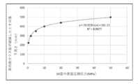
h1=59.923*S4+261.11 (2) In calculating the formula (1), the following studies were conducted. First, the present inventor has found that a laminated glass having both
h1 = 59.923 * S4 + 261.11 (2)
h1=(59.923*S4+261.11)*((t1+t2)/(2+2))2 (3) Based on this equation (2), if the thickness of each of the
h1 = (59.923 * S4 + 261.11) * ((t1 + t2) / (2 + 2)) 2 (3)
h2=(59.923*S2+261.11)*(t1/2)2(4) Next, the drop height when the
h2 = (59.923 * S2 + 261.11) * (t1 / 2) 2 (4)
次に、上記のように構成されたウインドシールドの製造方法の一例について説明する。まず、合わせガラス1の製造方法について説明する。 <5. Windshield manufacturing method>
Next, an example of a method for manufacturing the windshield configured as described above will be described. First, a method for manufacturing the laminated glass 1 will be described.
以上説明したウインドシールドによれば、外側ガラス板11の車外側の面の圧縮の主応力S1が大きくなっているため、例えば、ウインドシールドに対し、車外か外側ガラス板11に当たっても、その変形は小さい。このように変形が小さいと、圧縮の主応力S1が大きいことにより、割れを抑制することができる。 <6. Features>
According to the windshield described above, the principal stress S1 of the compression of the outer surface of the
以上、本発明の一実施形態について説明したが、本発明は上記実施形態に限定されるものではなく、その趣旨を逸脱しない限りにおいて、種々の変更が可能である。なお、以下の変形例は適宜組み合わせることができる。 <7. Modification example>
Although one embodiment of the present invention has been described above, the present invention is not limited to the above embodiment, and various modifications can be made without departing from the spirit of the present invention. The following modifications can be combined as appropriate.
上記実施形態では、外側ガラス板11の主応力S1,S2が概ね同じになっているが、例えば、図5に示すように、S1>S2とすることもできる。これにより、車内側の面の主応力S2が小さいため、内側ガラス板12が割れたときに、これに続いて、外側ガラス板11が割れやすくなる。具体的には、例えば、S2をS1よりも10MPa小さくすることができる。なお、このような主応力S1,S2の差を設けるには、例えば、プレス後に、外側ガラス板11の車外側の面を車内側の面よりも強く冷却すれば良い。 <7-1>
In the above embodiment, the principal stresses S1 and S2 of the
上記実施形態では、内側ガラス板12の主応力S3,S4が概ね同じになっているが、例えば、図6に示すように、S4<S3とすることもできる。これにより、車内側の面の圧縮の主応力S4が小さいため、車外からの人の衝突で引張の応力が車外側の面に作用したときに、より割れやすくなる。具体的には、例えば、S4をS3よりも10MPa小さくすることができる。なお、このような主応力S3,S4の差を設けるには、例えば、プレス後に、内側ガラス板12の車外側の面を車内側の面よりも強く冷却すれば良い。 <7-2>
In the above embodiment, the principal stresses S3 and S4 of the
上述したような主応力の分布は、合わせガラスの全体に亘って形成されていなくてもよく、一部であってもよい。一部に形成する場合には、例えば、少なくとも合わせガラスの上下方向の中央よりも下方に、そのような分布を形成することが好ましい。これは、ウインドシールドに車外から人が衝突するときには、ウインドシールドの下部に衝突することが多いからである。 <7-3>
The distribution of the principal stress as described above may not be formed over the entire laminated glass, or may be a part thereof. When it is formed in a part, for example, it is preferable to form such a distribution at least below the center in the vertical direction of the laminated glass. This is because when a person collides with the windshield from outside the vehicle, it often collides with the lower part of the windshield.
遮蔽層4の構成は特には限定されず、上述したように、各ガラス板の周縁部に沿って配置されるほか、図7に示すように、車載カメラ用の延在部42を設けることもできる。この延在部42には、カメラ用の撮影窓421が形成されており、車外を撮影することができるようになっている。また、この延在部42によって、カメラを支持するブラケットを車外から隠すこともできる。本発明に係る遮蔽層4は、このような延在部を設けるほか、種々の形状にすることができる。なお、遮蔽層4は必須ではなく、設けなくてもよい。 <7-4>
The configuration of the
実施例1~11及び比較例1,2に係るウインドシールドをシミュレーションにより作製した。以下の表2に示す主応力S1~S4は、上記実施形態で示したものと同じである。実施例1~11はS1がS4よりも大きくなっているが、比較例1,2はS1とS4とが同じである。

The windshields according to Examples 1 to 11 and Comparative Examples 1 and 2 were produced by simulation. The principal stresses S1 to S4 shown in Table 2 below are the same as those shown in the above embodiment. In Examples 1 to 11, S1 is larger than S4, but in Comparative Examples 1 and 2, S1 and S4 are the same.
次に、シミュレーションにより落球試験を行った。この試験では、半径が約95±1mmの10±0.2kgの球状の錘を想定し、上記実施例及び比較例に係るウインドシールドに落下させ、ガラス板が割れたときの高さ(以下、錘高さという)を算出した。したがって、錘高さが低いほど、錘のような人の頭ほどの物体の衝撃に対して割れやすいと考えられる。また、錘を車外から(外側ガラス板側から)落下させた場合と、車内から(内側ガラス板側から)落下させた場合の2種類の試験を行った。このとき、結果は、以下の通りである。

Next, a ball drop test was conducted by simulation. In this test, assuming a spherical weight of 10 ± 0.2 kg with a radius of about 95 ± 1 mm, the height when the glass plate is broken by dropping it on the windshield according to the above Examples and Comparative Examples (hereinafter, The weight height) was calculated. Therefore, it is considered that the lower the weight height, the more easily it breaks against the impact of an object such as a weight, which is about the size of a human head. In addition, two types of tests were conducted, one in which the weight was dropped from the outside of the vehicle (from the outer glass plate side) and the other in which the weight was dropped from the inside of the vehicle (from the inner glass plate side). At this time, the result is as follows.
A:錘の高さが634mm未満で両ガラス板が割れる。
B:錘の高さが634mm以上で両ガラス板が割れる。
なお、634mmは、上述したとおり、HICが概ね1000となる高さである。 The judgment in Table 3 is as follows.
A: Both glass plates break when the height of the weight is less than 634 mm.
B: Both glass plates break when the height of the weight is 634 mm or more.
As described above, 634 mm is a height at which the HIC is approximately 1000.

次の実験を行った。まず、飛び石の射出装置を上記実施例及び比較例に係るウインドシールドと1mの距離になるように配置する。次に、重さ2.0±0.2mmの石を64km/h(40MPh)で実施例及び比較例に係るウインドシールドに向かって射出する。1回の試験で、同一エリアの異なる箇所に5発飛石を発射し、コーンクラックが発生するかを確認する。そして、15箇所のエリアについて同様の試験を行い、コーンクラックが発生するか同様に確認する。最後に、全ての箇所でのコーンクラックの有無から発生率を算出する。 <3. Stepping stone test >
The following experiment was performed. First, the stepping stone injection device is arranged so as to have a distance of 1 m from the windshield according to the above embodiment and the comparative example. Next, a stone weighing 2.0 ± 0.2 mm is ejected at 64 km / h (40 MPh) toward the windshield according to Examples and Comparative Examples. In one test, 5 stepping stones are fired at different locations in the same area to check if cone cracks occur. Then, the same test is performed on 15 areas, and it is confirmed in the same manner whether or not cone cracks occur. Finally, the occurrence rate is calculated from the presence or absence of cone cracks at all locations.
A:発生率1%以下
B:発生率が1%より大きく、2%以下

A: Incidence rate 1% or less B: Occurrence rate is greater than 1% and 2% or less
11 外側ガラス板
12 内側ガラス板
13 中間膜
4 遮蔽層 10 Laminated
Claims (11)
- 外側ガラス板と、
前記外側ガラス板と対向配置される、内側ガラス板と、
前記外側ガラス板及び前記内側ガラス板の間に配置される、中間膜と、
を備え、
前記外側ガラス板及び前記内側ガラス板の少なくとも一部の領域において、前記外側ガラス板の車外側の面の圧縮の主応力が、前記内側ガラス板の車内側の面の圧縮の主応力より大きい、ウインドシールド。 With the outer glass plate,
An inner glass plate, which is arranged to face the outer glass plate,
An interlayer film arranged between the outer glass plate and the inner glass plate,
With
In at least a part of the outer glass plate and the inner glass plate, the compression principal stress of the vehicle outer surface of the outer glass plate is larger than the compression principal stress of the vehicle inner surface of the inner glass plate. Windshield. - 前記少なくとも一部の領域は、前記外側ガラス板及び前記内側ガラス板の上下方向の中央よりも下方の領域である、請求項1に記載のウインドシールド。 The windshield according to claim 1, wherein at least a part of the region is a region below the center of the outer glass plate and the inner glass plate in the vertical direction.
- 前記少なくとも一部の領域において、前記外側ガラス板の車外側の面の圧縮の主応力が、前記外側ガラス板の車内側の面の圧縮の主応力より大きい、請求項1または2に記載のウインドシールド。 The window according to claim 1 or 2, wherein in at least a part of the regions, the principal stress of compression of the vehicle outer surface of the outer glass plate is larger than the compression principal stress of the vehicle inner surface of the outer glass plate. shield.
- 前記少なくとも一部の領域において、前記内側ガラス板の車外側の面の圧縮の主応力が、前記内側ガラス板の車内側の面の圧縮の主応力より小さい、請求項1から3のいずれかに記載のウインドシールド。 According to any one of claims 1 to 3, in at least a part of the region, the principal stress of compression of the outer surface of the inner glass plate is smaller than the principal stress of compression of the inner surface of the inner glass plate. The listed windshield.
- 前記少なくとも一部の領域において、前記内側ガラス板の車外側の面の圧縮の主応力が、前記内側ガラス板の車内側の面の圧縮の主応力より大きい、請求項1から3のいずれかに記載のウインドシールド。 According to any one of claims 1 to 3, in at least a part of the region, the principal stress of compression of the vehicle outer surface of the inner glass plate is larger than the compression principal stress of the vehicle inner surface of the inner glass plate. The listed windshield.
- 前記外側ガラス板の厚みが、前記内側ガラス板の厚みよりも大きい、請求項1から5のいずれかに記載のウインドシールド。 The windshield according to any one of claims 1 to 5, wherein the thickness of the outer glass plate is larger than the thickness of the inner glass plate.
- 前記外側ガラス板の厚みが、0.7mm以上5.0mm以下であり、
前記内側ガラス板の厚みが、0.3mm以上3.0mm以下である、請求項1から6のいずれかに記載のウインドシールド。 The thickness of the outer glass plate is 0.7 mm or more and 5.0 mm or less.
The windshield according to any one of claims 1 to 6, wherein the inner glass plate has a thickness of 0.3 mm or more and 3.0 mm or less. - 前記少なくとも一部の領域において、前記外側ガラス板の車外側の面の圧縮の主応力が、5MPa以上50MPa以下である、請求項1から7のいずれかに記載のウインドシールド。 The windshield according to any one of claims 1 to 7, wherein in at least a part of the region, the main stress of compression of the outer surface of the outer glass plate is 5 MPa or more and 50 MPa or less.
- 前記外側ガラス板の厚みをt1、前記内側ガラス板の厚みt2、前記外側ガラス板の車内側の面の圧縮の主応力をS2、前記内側ガラス板の車内側の面の圧縮の主応力をS4としたとき、
S2*S4*(t12+t1*t2)2<1600、の関係式を満たす、請求項8に記載のウインドシールド。 The thickness of the outer glass plate is t1, the thickness of the inner glass plate is t2, the principal stress of compression of the inner surface of the outer glass plate is S2, and the principal stress of compression of the inner surface of the inner glass plate is S4. When
The windshield according to claim 8, which satisfies the relational expression of S2 * S4 * (t1 2 + t1 * t2) 2 <1600. - プレス法により、外側ガラス板を作製するステップと、
自重法により、内側ガラス板を作製するステップと、
前記外側ガラス板と前記内側ガラス板と間に中間膜を配置し、当該中間膜を介して前記外側ガラス板と内側ガラス板とを固定するステップと、
を備えている、ウインドシールドの製造方法。 Steps to make the outer glass plate by the press method,
Steps to make an inner glass plate by the self-weight method,
A step of arranging an interlayer film between the outer glass plate and the inner glass plate and fixing the outer glass plate and the inner glass plate via the interlayer film.
How to make a windshield. - プレス法により、外側ガラス板を作製するステップであって、プレス後の前記外側ガラス板に急冷を施す、ステップと、
プレス法により、外側ガラス板を作製するステップと、
プレス法により、内側ガラス板を作製するステップと、
前記外側ガラス板と前記内側ガラス板と間に中間膜を配置し、当該中間膜を介して前記外側ガラス板と内側ガラス板とを固定するステップと、
を備えている、ウインドシールドの製造方法。 A step of producing an outer glass plate by a pressing method, wherein the outer glass plate after pressing is rapidly cooled.
Steps to make the outer glass plate by the press method,
Steps to make the inner glass plate by the press method,
A step of arranging an interlayer film between the outer glass plate and the inner glass plate and fixing the outer glass plate and the inner glass plate via the interlayer film.
How to make a windshield.
Priority Applications (4)
| Application Number | Priority Date | Filing Date | Title |
|---|---|---|---|
| JP2022510779A JPWO2021193979A1 (en) | 2020-03-27 | 2021-03-29 | |
| EP21774146.1A EP4129938A4 (en) | 2020-03-27 | 2021-03-29 | Windshield |
| CN202180024766.1A CN115362075A (en) | 2020-03-27 | 2021-03-29 | Windscreen |
| US17/914,489 US20230111902A1 (en) | 2020-03-27 | 2021-03-29 | Windshield |
Applications Claiming Priority (2)
| Application Number | Priority Date | Filing Date | Title |
|---|---|---|---|
| JP2020059215 | 2020-03-27 | ||
| JP2020-059215 | 2020-03-27 |
Publications (1)
| Publication Number | Publication Date |
|---|---|
| WO2021193979A1 true WO2021193979A1 (en) | 2021-09-30 |
Family
ID=77891999
Family Applications (1)
| Application Number | Title | Priority Date | Filing Date |
|---|---|---|---|
| PCT/JP2021/013429 WO2021193979A1 (en) | 2020-03-27 | 2021-03-29 | Windshield |
Country Status (5)
| Country | Link |
|---|---|
| US (1) | US20230111902A1 (en) |
| EP (1) | EP4129938A4 (en) |
| JP (1) | JPWO2021193979A1 (en) |
| CN (1) | CN115362075A (en) |
| WO (1) | WO2021193979A1 (en) |
Citations (4)
| Publication number | Priority date | Publication date | Assignee | Title |
|---|---|---|---|---|
| JPH1160294A (en) * | 1997-06-10 | 1999-03-02 | Nippon Sheet Glass Co Ltd | Laminated glass for vehicle |
| JP2015525193A (en) * | 2012-06-01 | 2015-09-03 | コーニング インコーポレイテッド | Glass laminate construction for optimized failure performance |
| JP2016064965A (en) | 2013-10-10 | 2016-04-28 | セントラル硝子株式会社 | Method for producing laminated glass for vehicle |
| JP2019119631A (en) * | 2017-12-28 | 2019-07-22 | 日本板硝子株式会社 | Windshield |
-
2021
- 2021-03-29 JP JP2022510779A patent/JPWO2021193979A1/ja active Pending
- 2021-03-29 US US17/914,489 patent/US20230111902A1/en active Pending
- 2021-03-29 EP EP21774146.1A patent/EP4129938A4/en active Pending
- 2021-03-29 WO PCT/JP2021/013429 patent/WO2021193979A1/en active Application Filing
- 2021-03-29 CN CN202180024766.1A patent/CN115362075A/en active Pending
Patent Citations (4)
| Publication number | Priority date | Publication date | Assignee | Title |
|---|---|---|---|---|
| JPH1160294A (en) * | 1997-06-10 | 1999-03-02 | Nippon Sheet Glass Co Ltd | Laminated glass for vehicle |
| JP2015525193A (en) * | 2012-06-01 | 2015-09-03 | コーニング インコーポレイテッド | Glass laminate construction for optimized failure performance |
| JP2016064965A (en) | 2013-10-10 | 2016-04-28 | セントラル硝子株式会社 | Method for producing laminated glass for vehicle |
| JP2019119631A (en) * | 2017-12-28 | 2019-07-22 | 日本板硝子株式会社 | Windshield |
Also Published As
| Publication number | Publication date |
|---|---|
| EP4129938A4 (en) | 2024-05-15 |
| JPWO2021193979A1 (en) | 2021-09-30 |
| US20230111902A1 (en) | 2023-04-13 |
| EP4129938A1 (en) | 2023-02-08 |
| CN115362075A (en) | 2022-11-18 |
Similar Documents
| Publication | Publication Date | Title |
|---|---|---|
| US11691390B2 (en) | Light-weight hybrid glass laminates | |
| WO2019131802A1 (en) | Windshield | |
| US20190308394A1 (en) | Composite glass pane | |
| JP6770470B2 (en) | Windshield | |
| JP6069213B2 (en) | Laminated window glass | |
| US20070014976A1 (en) | Thermoplastic resin sheet and laminate | |
| US20120328843A1 (en) | Light-weight hybrid glass laminates | |
| US20170341347A1 (en) | Laminated glass | |
| WO2014126251A1 (en) | Laminated glass, and structure having same mounted thereto | |
| WO2015006201A1 (en) | Light-weight hybrid glass laminates | |
| JP6947176B2 (en) | Laminated glass | |
| US20170274738A1 (en) | Laminated glass | |
| JP7181478B2 (en) | LAMINATED GLASS FOR AUTOMOBILE WINDSHIELD AND METHOD FOR MANUFACTURING THE SAME | |
| WO2019131800A1 (en) | Windshield | |
| WO2019235449A1 (en) | Laminated glass | |
| WO2021193979A1 (en) | Windshield | |
| JP6988157B2 (en) | Laminated glass | |
| WO2021193647A1 (en) | Windshield | |
| JP6945443B2 (en) | Glass plate module | |
| WO2022270634A1 (en) | Windshield | |
| EP4364985A1 (en) | Windshield | |
| US20200361183A1 (en) | Laminated glass | |
| JP2021147298A (en) | Windshield, and production method thereof |
Legal Events
| Date | Code | Title | Description |
|---|---|---|---|
| 121 | Ep: the epo has been informed by wipo that ep was designated in this application |
Ref document number: 21774146 Country of ref document: EP Kind code of ref document: A1 |
|
| ENP | Entry into the national phase |
Ref document number: 2022510779 Country of ref document: JP Kind code of ref document: A |
|
| WWE | Wipo information: entry into national phase |
Ref document number: 2021774146 Country of ref document: EP |
|
| ENP | Entry into the national phase |
Ref document number: 2021774146 Country of ref document: EP Effective date: 20221027 |
|
| NENP | Non-entry into the national phase |
Ref country code: DE |