WO2021193814A1 - Imaging device - Google Patents
Imaging device Download PDFInfo
- Publication number
- WO2021193814A1 WO2021193814A1 PCT/JP2021/012511 JP2021012511W WO2021193814A1 WO 2021193814 A1 WO2021193814 A1 WO 2021193814A1 JP 2021012511 W JP2021012511 W JP 2021012511W WO 2021193814 A1 WO2021193814 A1 WO 2021193814A1
- Authority
- WO
- WIPO (PCT)
- Prior art keywords
- exposure
- range
- amount
- imaging device
- imaging
- Prior art date
Links
Images


Classifications
-
- G—PHYSICS
- G03—PHOTOGRAPHY; CINEMATOGRAPHY; ANALOGOUS TECHNIQUES USING WAVES OTHER THAN OPTICAL WAVES; ELECTROGRAPHY; HOLOGRAPHY
- G03B—APPARATUS OR ARRANGEMENTS FOR TAKING PHOTOGRAPHS OR FOR PROJECTING OR VIEWING THEM; APPARATUS OR ARRANGEMENTS EMPLOYING ANALOGOUS TECHNIQUES USING WAVES OTHER THAN OPTICAL WAVES; ACCESSORIES THEREFOR
- G03B7/00—Control of exposure by setting shutters, diaphragms or filters, separately or conjointly
- G03B7/08—Control effected solely on the basis of the response, to the intensity of the light received by the camera, of a built-in light-sensitive device
- G03B7/091—Digital circuits
-
- G—PHYSICS
- G06—COMPUTING; CALCULATING OR COUNTING
- G06V—IMAGE OR VIDEO RECOGNITION OR UNDERSTANDING
- G06V10/00—Arrangements for image or video recognition or understanding
- G06V10/40—Extraction of image or video features
- G06V10/60—Extraction of image or video features relating to illumination properties, e.g. using a reflectance or lighting model
-
- G—PHYSICS
- G03—PHOTOGRAPHY; CINEMATOGRAPHY; ANALOGOUS TECHNIQUES USING WAVES OTHER THAN OPTICAL WAVES; ELECTROGRAPHY; HOLOGRAPHY
- G03B—APPARATUS OR ARRANGEMENTS FOR TAKING PHOTOGRAPHS OR FOR PROJECTING OR VIEWING THEM; APPARATUS OR ARRANGEMENTS EMPLOYING ANALOGOUS TECHNIQUES USING WAVES OTHER THAN OPTICAL WAVES; ACCESSORIES THEREFOR
- G03B13/00—Viewfinders; Focusing aids for cameras; Means for focusing for cameras; Autofocus systems for cameras
- G03B13/32—Means for focusing
- G03B13/34—Power focusing
-
- G—PHYSICS
- G03—PHOTOGRAPHY; CINEMATOGRAPHY; ANALOGOUS TECHNIQUES USING WAVES OTHER THAN OPTICAL WAVES; ELECTROGRAPHY; HOLOGRAPHY
- G03B—APPARATUS OR ARRANGEMENTS FOR TAKING PHOTOGRAPHS OR FOR PROJECTING OR VIEWING THEM; APPARATUS OR ARRANGEMENTS EMPLOYING ANALOGOUS TECHNIQUES USING WAVES OTHER THAN OPTICAL WAVES; ACCESSORIES THEREFOR
- G03B7/00—Control of exposure by setting shutters, diaphragms or filters, separately or conjointly
- G03B7/08—Control effected solely on the basis of the response, to the intensity of the light received by the camera, of a built-in light-sensitive device
- G03B7/091—Digital circuits
- G03B7/095—Digital circuits for control of aperture
-
- G—PHYSICS
- G03—PHOTOGRAPHY; CINEMATOGRAPHY; ANALOGOUS TECHNIQUES USING WAVES OTHER THAN OPTICAL WAVES; ELECTROGRAPHY; HOLOGRAPHY
- G03B—APPARATUS OR ARRANGEMENTS FOR TAKING PHOTOGRAPHS OR FOR PROJECTING OR VIEWING THEM; APPARATUS OR ARRANGEMENTS EMPLOYING ANALOGOUS TECHNIQUES USING WAVES OTHER THAN OPTICAL WAVES; ACCESSORIES THEREFOR
- G03B7/00—Control of exposure by setting shutters, diaphragms or filters, separately or conjointly
- G03B7/08—Control effected solely on the basis of the response, to the intensity of the light received by the camera, of a built-in light-sensitive device
- G03B7/091—Digital circuits
- G03B7/097—Digital circuits for control of both exposure time and aperture
-
- G—PHYSICS
- G03—PHOTOGRAPHY; CINEMATOGRAPHY; ANALOGOUS TECHNIQUES USING WAVES OTHER THAN OPTICAL WAVES; ELECTROGRAPHY; HOLOGRAPHY
- G03B—APPARATUS OR ARRANGEMENTS FOR TAKING PHOTOGRAPHS OR FOR PROJECTING OR VIEWING THEM; APPARATUS OR ARRANGEMENTS EMPLOYING ANALOGOUS TECHNIQUES USING WAVES OTHER THAN OPTICAL WAVES; ACCESSORIES THEREFOR
- G03B7/00—Control of exposure by setting shutters, diaphragms or filters, separately or conjointly
- G03B7/18—Control of exposure by setting shutters, diaphragms or filters, separately or conjointly in accordance with light-reducing "factor" of filter or other obturator used with or on the lens of the camera
-
- G—PHYSICS
- G06—COMPUTING; CALCULATING OR COUNTING
- G06V—IMAGE OR VIDEO RECOGNITION OR UNDERSTANDING
- G06V10/00—Arrangements for image or video recognition or understanding
- G06V10/10—Image acquisition
- G06V10/12—Details of acquisition arrangements; Constructional details thereof
- G06V10/14—Optical characteristics of the device performing the acquisition or on the illumination arrangements
- G06V10/141—Control of illumination
-
- H—ELECTRICITY
- H04—ELECTRIC COMMUNICATION TECHNIQUE
- H04N—PICTORIAL COMMUNICATION, e.g. TELEVISION
- H04N23/00—Cameras or camera modules comprising electronic image sensors; Control thereof
-
- H—ELECTRICITY
- H04—ELECTRIC COMMUNICATION TECHNIQUE
- H04N—PICTORIAL COMMUNICATION, e.g. TELEVISION
- H04N23/00—Cameras or camera modules comprising electronic image sensors; Control thereof
- H04N23/70—Circuitry for compensating brightness variation in the scene
-
- H—ELECTRICITY
- H04—ELECTRIC COMMUNICATION TECHNIQUE
- H04N—PICTORIAL COMMUNICATION, e.g. TELEVISION
- H04N23/00—Cameras or camera modules comprising electronic image sensors; Control thereof
- H04N23/70—Circuitry for compensating brightness variation in the scene
- H04N23/75—Circuitry for compensating brightness variation in the scene by influencing optical camera components
-
- H—ELECTRICITY
- H04—ELECTRIC COMMUNICATION TECHNIQUE
- H04N—PICTORIAL COMMUNICATION, e.g. TELEVISION
- H04N23/00—Cameras or camera modules comprising electronic image sensors; Control thereof
- H04N23/70—Circuitry for compensating brightness variation in the scene
- H04N23/76—Circuitry for compensating brightness variation in the scene by influencing the image signals
-
- G—PHYSICS
- G03—PHOTOGRAPHY; CINEMATOGRAPHY; ANALOGOUS TECHNIQUES USING WAVES OTHER THAN OPTICAL WAVES; ELECTROGRAPHY; HOLOGRAPHY
- G03B—APPARATUS OR ARRANGEMENTS FOR TAKING PHOTOGRAPHS OR FOR PROJECTING OR VIEWING THEM; APPARATUS OR ARRANGEMENTS EMPLOYING ANALOGOUS TECHNIQUES USING WAVES OTHER THAN OPTICAL WAVES; ACCESSORIES THEREFOR
- G03B2205/00—Adjustment of optical system relative to image or object surface other than for focusing
- G03B2205/0046—Movement of one or more optical elements for zooming
-
- G—PHYSICS
- G06—COMPUTING; CALCULATING OR COUNTING
- G06T—IMAGE DATA PROCESSING OR GENERATION, IN GENERAL
- G06T2207/00—Indexing scheme for image analysis or image enhancement
- G06T2207/10—Image acquisition modality
- G06T2207/10141—Special mode during image acquisition
- G06T2207/10144—Varying exposure
Definitions
- the present invention relates to an imaging device, and more particularly to an imaging device that captures moving images.
- a technique for controlling exposure using a transmittance control element such as a variable ND filter is known (Patent Documents 1-3, etc.).
- One embodiment according to the technique of the present disclosure provides an imaging device capable of continuously capturing a natural moving image even when the brightness changes.
- An image pickup device in which exposure conditions are set based on the characteristics of a transmittance control element, comprising a processor, the processor calculates a first exposure condition range based on the light measurement of the image pickup device, and first exposure.
- the condition range is not included in the second exposure condition range to which the control range acquired by the transmittance control element can be applied, imaging is performed so that the calculated first exposure condition range is included in the second exposure condition range.
- An imaging device that changes the exposure conditions of the device.
- the processor determines the imaging scene information based on the photometric measurement of the imaging device, and calculates the first exposure condition range based on the determined imaging scene information.
- the processor During imaging, if the third exposure condition range calculated based on the photometric measurement of the imaging device is different from the first exposure condition range, the processor so that the second exposure condition range is included in the third exposure condition range.
- the image pickup device of (3) which changes the exposure condition of the image pickup device.
- An imaging device according to any one of (1) to (4), wherein the exposure conditions are an aperture control amount, a shutter speed control amount, and a sensitivity control amount.
- the processor changes the aperture control amount, the shutter speed control amount, and the sensitivity control amount in a predetermined priority order, according to (9).
- the processor changes the aperture control amount, the shutter speed control amount, and the sensitivity control amount in a predetermined priority order, according to (9).
- the order of priority is the shutter speed control amount in the range from the maximum value to 1/2 of the maximum value, the sensitivity control amount, the shutter speed control amount of 1/2 of the maximum value, and the aperture control amount. (10) Imaging apparatus.
- the processor measures the fluctuation range of the exposure amount when the moving image is captured, records the information of the fluctuation range of the measured exposure amount in the memory, and the history information of the fluctuation range of the exposure amount recorded in the memory.
- the imaging device according to any one of (1) to (11), which sets the first exposure condition range based on the above.
- the processor acquires information on the fluctuation range of the exposure amount expected when the moving image is captured in advance, and sets the first exposure condition range based on the information on the fluctuation range of the exposure amount acquired.
- the imaging device according to any one of (1) to (11).
- the processor acquires information on the fluctuation range of the exposure amount in the region for capturing a moving image in advance, and sets the first exposure condition range based on the information on the fluctuation range of the exposure amount acquired.
- the figure which shows the schematic structure of the image pickup apparatus Block diagram of functions related to exposure control The figure which shows an example of the area division Conceptual diagram of judgment of necessity of correction Conceptual diagram of judgment of necessity of correction Conceptual diagram of correction of variable ND filter settings Flow chart showing the procedure for setting the exposure control amount when starting imaging Flowchart showing the procedure of exposure control during imaging Flow chart showing the procedure of exposure control during imaging when the exposure control mode is auto mode Flowchart showing the procedure of the exposure control amount setting process Conceptual diagram of calculation of estimated exposure fluctuation range
- the movable range of the transmittance control element is limited. Therefore, if the transmittance control element is set near the upper limit value or the lower limit value of the movable range when starting the imaging of a moving image, the exposure may not be controlled by the transmittance control element alone during imaging. There is. On the other hand, if the transmittance control element is forcibly set to the median value of the movable range, it becomes impossible to capture a moving image under the exposure conditions (aperture value, shutter speed and imaging sensitivity) desired by the user.
- an imaging device capable of continuously capturing a natural moving image even if the brightness changes while maintaining the exposure conditions set by the user as much as possible is provided.
- FIG. 1 is a diagram showing a schematic configuration of an imaging device.
- the image sensor 1 of the present embodiment mainly includes an image sensor 10, an image sensor 20, an image sensor drive unit 22, an analog signal processing unit 24, an ADC (Analog to Digital Converter) 26, and a main memory.
- a unit 28 a digital signal processing unit 30, an auxiliary storage unit 32, a display unit 34, an operation unit 36, a system control unit 40, and the like are provided.
- the image pickup lens 10 mainly includes a lens 11, an aperture 12, a variable ND filter 13, a lens drive unit 14, an aperture drive unit 15, an ND filter drive unit 16, and the like. Although only one lens 11 is shown in FIG. 1 for convenience, the image pickup lens 10 is provided with a plurality of lenses.
- the image pickup lens 10 is composed of, for example, a zoom lens.
- the image pickup lens 10 zooms by moving the zoom lens group back and forth along the optical axis. Further, the image pickup lens 10 has a focus adjustment mechanism, and the focus is adjusted by moving the focus lens group back and forth along the optical axis.
- the lens driving unit 14 moves the zoom lens group and the focus lens group back and forth along the optical axis.
- the diaphragm 12 is composed of, for example, an iris diaphragm.
- the diaphragm 12 is arranged in the optical path of the image pickup lens 10 to adjust the amount of light passing through the image pickup lens 10.
- the diaphragm 12 is driven by the diaphragm drive unit 15 to change the opening amount.
- the variable ND filter 13 is arranged in the optical path of the image pickup lens 10 to uniformly reduce the amount of light passing through the image pickup lens 10.
- the variable ND filter 13 is an ND filter in which the reduction rate of the amount of light is variable.
- an electronic variable ND filter 13 is used.
- the reduction rate of the amount of light changes depending on the applied voltage.
- a variable ND filter 13 in which the reduction rate of the amount of light changes in the range of 1/4 to 1/128 is used.
- the variable ND filter 13 is an example of a transmittance control element.
- the variable ND filter 13 is driven by the ND filter driving unit 16 to change the reduction rate of the amount of light.
- the image sensor 20 is composed of a color area image sensor.
- the image sensor is composed of, for example, an image sensor of a CMOS (CMOS: Complementary Mental-Oxide Semiconductor) type or a CCD (CCD: Charged Coupled Device) type having a predetermined color filter array (for example, a Bayer array or the like).
- CMOS Complementary Mental-Oxide Semiconductor
- CCD Charged Coupled Device
- the image sensor 20 is driven by the image sensor drive unit 22 to operate.
- the image pickup device 1 adjusts the exposure time (shutter speed) by electronically controlling the on and off of the image pickup device 20 (so-called electronic shutter function).
- the analog signal processing unit 24 performs predetermined signal processing on the analog image signal output from the image sensor 20.
- the analog signal processing unit 24 includes a sampling hold circuit, a color separation circuit, an AGC circuit (Automatic Gain Control circuit), and the like.
- the AGC circuit functions as a sensitivity adjusting unit for adjusting the imaging sensitivity (ISO (International Organization for Standardization)).
- the ADC 26 converts an analog image signal that has undergone predetermined signal processing by the analog signal processing unit 24 into a digital image signal.
- the image sensor drive unit 22, the analog signal processing unit 24, and the ADC 26 are often included in the image sensor 20. Further, when the image pickup element 20 is composed of a CMOS type image sensor, a digital image sensor signal processing unit is often provided instead of the analog signal processing unit 24.
- the image sensor 20 When the image sensor 20 is composed of a CMOS type image sensor including an ADC and a digital image sensor signal processing unit, the image sensor 20 outputs a signal of each pixel as follows.
- the signal of each pixel is amplified by an analog amplification unit provided for each pixel or each of a plurality of pixels, read out in units of rows, and supplied to the ADC.
- the ADC converts the supplied signal of each pixel into a digital signal and supplies it to the image sensor signal processing unit.
- the image sensor signal processing unit performs various signal processing such as digital correlation double sampling processing, digital gain processing, and correction processing on the supplied digital signal of each pixel.
- a signal subjected to various signal processing by the signal processing unit is output from the image sensor 20.
- the main storage unit 28 is used as a temporary storage area for data.
- the image signal output from the image sensor 20 passes through the analog signal processing unit 24 and the ADC 26, and is stored in the main storage unit 28 for each frame.
- the digital signal processing unit 30 performs signal processing such as offset processing, gamma correction processing, demosaic processing, and RGB / YCrCb conversion processing on the image signal converted into a digital signal to generate image data.
- the digital signal processing unit 30 is composed of, for example, a microprocessor.
- the auxiliary storage unit 32 mainly stores image data obtained by imaging.
- the auxiliary storage unit 32 is composed of an internal memory and / or an external memory.
- the built-in memory is a memory built in the main body of the image pickup apparatus 1.
- the built-in memory is composed of, for example, a non-volatile semiconductor memory.
- the external memory is composed of, for example, a memory card, and is loaded into a card slot provided in the image pickup apparatus main body.
- the display unit 34 is used for reproducing the captured image, and also displays the live view image at the time of imaging. It is also used as a setting screen when making various settings.
- the display unit 34 is composed of, for example, a display such as an LCD (Liquid Crystal Display) or an OLED (Organic Light Emitting Diode).
- the operation unit 36 includes various operation members for operating the image pickup device 1.
- the operating members include an operating member (power button) for turning on and off the power of the imaging device 1, an operating member (recording button) for instructing the start and end of imaging, an operating member for making various settings, and the like.
- the operating members for setting various settings include, for example, an operating member for setting the exposure control mode, an operating member for setting the aperture value, an operating member for setting the shutter speed, an operating member for setting the imaging sensitivity, and the like.
- the operating member for setting the exposure control mode is, for example, a mode dial.
- the exposure control mode includes, for example, an auto mode, an aperture priority mode, a shutter speed priority mode, a manual mode, and the like.
- the auto mode is a mode in which the aperture value, shutter speed, and imaging sensitivity are automatically set.
- the aperture priority mode is a mode in which the shutter speed and the imaging sensitivity are automatically set according to the set aperture value.
- the shutter speed priority mode is a mode in which the aperture value and the imaging sensitivity are automatically set according to the set shutter speed.
- the manual mode is a mode in which the aperture value and the shutter speed are set manually.
- the operating member for setting the aperture value is, for example, an aperture ring.
- the operating member for setting the shutter speed is, for example, a shutter speed dial.
- the operating member for setting the imaging sensitivity is, for example, an imaging sensitivity dial. It should be noted that these settings can also be configured to be set on the screen by using an operation member such as the display unit 34 and the cross key.
- the operation unit 36 outputs a signal corresponding to the operation of each operation member to the system control unit 40.
- the system control unit 40 controls the operation of each part of the image pickup device 1 and controls the overall operation of the image pickup device 1 in an integrated manner. Further, the system control unit 40 performs a calculation process of a physical quantity required for control and the like.
- the system control unit 40 is composed of, for example, a microcomputer provided with a processor and a memory.
- the processor is composed of, for example, a CPU (Central Processing Unit) or the like.
- the memory is composed of, for example, a RAM (Random Access Memory), a ROM (Read Only Memory), and the like.
- the memory stores programs executed by the processor and various data.
- the control performed by the system control unit 40 includes exposure control.
- the exposure is controlled by the aperture 12, the shutter speed, the image pickup sensitivity, and the variable ND filter 13.
- the exposure control performed when the image pickup device 1 of the present embodiment captures a moving image will be described.
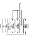
- FIG. 2 is a block diagram of functions related to exposure control.
- the system control unit 40 functions as an exposure control mode determination unit 40A, a photometric unit 40B, an exposure control amount setting unit 40C, an exposure change amount estimation unit 40D, and an exposure control amount correction unit 40E regarding exposure control. do.
- the exposure control mode determination unit 40A determines the set exposure control mode.
- the exposure control mode determination unit 40A determines the exposure control mode based on the information from the operation unit 36. Specifically, the currently set exposure control mode (auto mode, aperture priority mode, shutter speed priority mode, manual mode, etc.) is determined based on the mode dial setting.
- the photometric unit 40B measures the brightness of the subject based on the image signal output from the image sensor 20.
- the photometric unit 40B measures the brightness of the subject and calculates the exposure amount.
- the exposure amount is calculated as, for example, an EV value (Exposure Value).
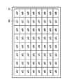
- the light receiving surface of the image pickup device 20 is divided into a plurality of regions, light is measured for each region, and the exposure amount is calculated.
- FIG. 3 is a diagram showing an example of region division. As shown in the figure, in the image pickup apparatus of the present embodiment, the light receiving surface 20A of the image pickup device 20 is equally divided into 8 ⁇ 8 regions a11 to a88.
- the exposure control amount setting unit 40C sets the exposure control amount. That is, the aperture value, shutter speed, imaging sensitivity, and reduction rate of the amount of light are set. In particular, the aperture value, shutter speed and imaging sensitivity are set as exposure conditions.
- the aperture value is an example of the aperture control amount.
- the shutter speed is an example of a shutter speed control amount.
- the imaging sensitivity is an example of the sensitivity control amount.
- the exposure control amount setting unit 40C sets an exposure control amount having a desired brightness based on the light measurement result of the light measurement unit 40B. For example, the light measurement result of each region is weighted to obtain the total exposure amount, and the exposure control amount to obtain the desired brightness is set based on the obtained total exposure amount.
- the desired brightness is, for example, a brightness that provides proper exposure. Normally, each exposure control amount is set so as to obtain an appropriate exposure. Further, for example, when exposure compensation is performed, each exposure control amount is set so that the exposure is compensated.
- the exposure control amount setting unit 40C sets each exposure control amount according to the currently set exposure control mode.
- the variable ND filter 13 is set to the median value of the movable range, and each exposure control amount is set.
- the aperture priority mode the aperture value is fixed and each exposure control amount is set.
- the shutter speed priority mode the shutter speed is fixed and each exposure control amount is set.
- the manual mode the aperture value and shutter speed are fixed and each exposure control amount is set.
- the exposure control amount is set according to a predetermined standard so as to obtain a desired brightness. For example, it is set according to a program diagram or the like.
- the exposure change amount estimation unit 40D estimates the exposure change amount of the scene to be imaged.
- the exposure change amount estimation unit 40D estimates the exposure change amount based on the light measurement result (exposure amount of each region a11 to a88) of the light measuring unit 40B.
- the amount of change in exposure is estimated as follows. First, information on the exposure amount of each region a11 to a88 is acquired. Next, the darkest region and the brightest region are specified based on the acquired exposure amount information of each region a11 to a88. Next, the range of the exposure amount covering the specified darkest area to the brightest area is obtained. The obtained range is used as the estimated exposure change amount. In this case, for example, when the exposure amount in the darkest region is 10 EV and the exposure amount in the brightest region is 15 EV, the range of 10 EV to 15 EV is calculated as the estimated exposure change amount.
- the exposure control amount correction unit 40E corrects each exposure control amount set by the exposure control amount setting unit 40C, if necessary.
- the exposure control amount correction unit 40E sets the characteristics of the variable ND filter 13, the set value of the variable ND filter 13, the exposure change amount (estimated exposure change amount) estimated by the exposure change amount estimation unit 40D, and the exposure control amount. The necessity of correction is determined based on the exposure amount at that time.
- the characteristic of the variable ND filter 13 is specifically the control range of the variable ND filter 13.
- the control range of the variable ND filter 13 is specified as a movable range of the variable ND filter 13.
- the movable range of the variable ND filter 13 is a so-called movable width, which is a range of a changeable reduction rate of the amount of light. In the case of the variable ND filter 13 of the present embodiment, the movable range is in the range of 1/4 to 1/128.
- FIG. 4 and 5 are conceptual diagrams for determining the necessity of correction.
- FIG. 4 shows an example in the case where correction is unnecessary.
- FIG. 5 shows an example when correction is required.
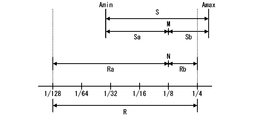
- the exposure control amount correction unit 40E determines that correction is necessary when the estimated exposure fluctuation range S is not included in the settable range R of the variable ND filter 13.
- the estimated exposure fluctuation range S is the fluctuation range of the exposure amount predicted when a moving image is captured.
- the estimated exposure fluctuation range S the estimated exposure fluctuation range Sa on the dark side and the estimated exposure fluctuation range Sb on the bright side are obtained based on the exposure amount M when the exposure control amount is set.
- the exposure amount M when the exposure control amount is set represents the brightness (exposure amount) of the current subject.
- the estimated exposure fluctuation range S is calculated based on the estimated exposure variate. For example, when the estimated exposure change amount is Amin to Amax (Amin is the minimum value of the estimated exposure change amount, Amax is the maximum value of the estimated exposure change amount), the range of Amin to M is the estimated exposure variation on the dark side. The range Sa. Further, the range of M to Amax is the estimated exposure fluctuation range Sb on the brightening side.
- the estimated exposure fluctuation range S is an example of the first exposure condition range.
- the settable range R of the variable ND filter 13 is a range to which the control range of the variable ND filter 13 can be applied.
- the settable range R of the variable ND filter 13 is the settable range Ra in the direction of lowering the reduction rate (brightening direction) and the reduction rate based on the current set value N (currently set reduction rate of the amount of light).
- the settable range Rb in the direction of increasing the rate (direction of darkening) is obtained.
- the range of 1/4 to N is the settable range Ra in the direction of lowering the reduction rate
- the range of N to 1/128 is the reduction rate. It becomes the settable range Rb in the raising direction.
- the settable range R of the variable ND filter 13 is an example of the second exposure condition range.
- the estimated exposure fluctuation range S is included in the settable range R of the variable ND filter 13. In this case, exposure control during imaging is possible only with the variable ND filter 13. Therefore, when the estimated exposure fluctuation range S is included in the settable range R of the variable ND filter 13, the exposure control amount correction unit 40E corrects the exposure control amount set by the exposure control amount setting unit 40C. Judged as unnecessary.
- the estimated exposure fluctuation range S exceeds the settable range R of the variable ND filter 13. That is, the settable range Rb in the direction of increasing the reduction rate is insufficient with respect to the estimated exposure fluctuation range Sb on the brightening side. In this case, the variable ND filter 13 alone cannot follow the change in brightness. Therefore, in this case, the exposure control amount correction unit 40E determines that the exposure control amount correction set by the exposure control amount setting unit 40C is necessary.
- the exposure control amount correction unit 40E corrects the exposure control amount so that the estimated exposure fluctuation range S is included in the settable range R of the variable ND filter 13. That is, the estimated exposure fluctuation range Sa on the dark side is within the range of the settable range Ra in the direction of lowering the reduction rate, and the estimated exposure fluctuation range Sb on the bright side can be set in the direction of increasing the reduction rate.
- the exposure control amount is corrected so as to be within the range Rb.
- the correction is performed, for example, in the following procedure.
- the set value of the variable ND filter 13 is corrected so that the estimated exposure fluctuation range is included in the settable range of the variable ND filter 13. That is, the currently set reduction rate of the amount of light is corrected.
- FIG. 6 is a conceptual diagram of correction of the variable ND filter setting. The figure shows an example of the case of correcting from the state of FIG.
- the settable range Rb in the direction of increasing the reduction rate is insufficient with respect to the estimated exposure fluctuation range Sb on the brightening side. Therefore, in this case, the set value of the variable ND filter 13 is corrected in the direction of lowering the reduction rate. At this time, it is preferable to set the correction amount to the minimum. As a result, when correcting other exposure control amounts, the correction amount can be reduced. That is, it is possible to maintain a state as close to the current exposure conditions as possible.
- the set value of the variable ND filter 13 is corrected so that the estimated exposure fluctuation range Sb on the brightening side and the settable range Rb in the direction of increasing the reduction rate match.
- each exposure control amount is corrected according to the currently set exposure control mode. That is, when the exposure control mode is set to the aperture priority mode, the exposure control amount other than the aperture value is corrected. When the exposure control mode is set to the shutter speed priority mode, the exposure control amount other than the shutter speed is corrected. When the exposure control mode is set to the manual mode, the exposure control amount other than the aperture value and the shutter speed is corrected.
- the desired brightness cannot be set only by the changeable exposure control amount.
- the desired brightness cannot be set only by correcting the imaging sensitivity.
- the fixed exposure control amount is also corrected.
- the corrected exposure control amount is taken as the exposure control amount at the time of imaging. If no correction is made, the exposure control amount set by the exposure control amount setting unit 40C is used as the exposure control amount at the time of imaging.
- each exposure control amount at the start of imaging is set as follows.
- FIG. 7 is a flowchart showing a procedure for setting the exposure control amount when starting imaging.
- step S1 when the instruction to start imaging is instructed, the photometric processing is performed (step S1).
- the instruction to start imaging is given by pressing the record button. By metering, the amount of exposure for each area can be obtained.
- the exposure control amount is set based on the metering result (step S2).
- This exposure control amount is a temporary exposure control amount.
- the exposure control amount is set according to the set exposure control mode. Specifically, it is set as follows.
- variable ND filter 13 is set to the median value of the movable range, and the remaining exposure control amount is set so as to obtain the desired brightness (for example, proper exposure). Is set. That is, the aperture value, shutter speed, and imaging sensitivity are set.
- the remaining exposure control amount is set so that the desired brightness is obtained after fixing the aperture value. That is, the shutter speed, the imaging sensitivity, and the reduction rate of the amount of light are set.
- the aperture value is determined based on the information from the operation unit 36.
- the remaining exposure control amount is set so that the desired brightness is obtained after fixing the shutter speed. That is, the aperture value, the imaging sensitivity, and the reduction rate of the amount of light are set.
- the shutter speed is determined based on the information from the operation unit 36.
- the remaining exposure control amount is set so that the desired brightness is obtained after fixing the aperture value and the shutter speed. That is, the imaging sensitivity and the reduction rate of the amount of light are set.
- the aperture value and the shutter speed are determined based on the information from the operation unit 36.
- the estimated exposure change amount is calculated based on the light measurement result (step S3).
- the estimated exposure change amount is calculated by obtaining the range of the exposure amount covering the darkest area to the brightest area in the image based on the light measurement result of each area.
- the estimated exposure fluctuation range S is calculated based on the estimated exposure change amount (step S4).
- the estimated exposure fluctuation range S the estimated exposure fluctuation range Sa on the dark side and the estimated exposure fluctuation range Sb on the bright side are calculated based on the exposure amount M when the exposure control amount is set.
- the settable range R of the variable ND filter 13 is calculated based on the movable range of the variable ND filter 13 (step S5).
- the settable range R of the variable ND filter 13 is calculated by calculating the settable range Ra in the direction of lowering the reduction rate and the settable range Rb in the direction of increasing the reduction rate with reference to the set value N of the current variable ND filter 13. Will be done.
- Step S6 based on the calculation results of the estimated exposure fluctuation range S and the settable range R of the variable ND filter 13, it is determined whether or not the estimated exposure fluctuation range S is included in the settable range R of the variable ND filter 13.
- the fluctuation range of the predicted exposure amount is within the range of the settable range R of the variable ND filter 13. This is the case when it fits (see FIG. 4). In this case, the exposure can be controlled only by the variable ND filter 13 during moving image imaging.
- the estimated exposure fluctuation range S is not included in the settable range R of the variable ND filter 13
- the predicted fluctuation range of the exposure amount falls within the range of the settable range R of the variable ND filter 13. This is the case (see FIG. 5).
- the exposure cannot be controlled only by the variable ND filter 13 during moving image imaging. That is, it becomes necessary to change other exposure control amounts during imaging.
- step S6 determines whether the estimated exposure fluctuation range S is not included in the settable range R of the variable ND filter 13 (in the case of "No" in the determination in step S6).
- the control amount provisional exposure control amount
- the exposure control amount is corrected as follows, for example. First, the set value of the variable ND filter 13 is changed so that the estimated exposure fluctuation range is included in the settable range of the variable ND filter 13. That is, the currently set reduction rate of the amount of light is changed. After changing the set value of the variable ND filter 13, other exposure control amounts are changed.
- the aperture value, the shutter speed, and the imaging sensitivity are changed so as to obtain the desired brightness under the newly set reduction rate of the amount of light.
- the corrected exposure control amount is taken as the exposure control amount at the start of imaging.
- the correction is also performed according to the currently set exposure control mode. Therefore, in the aperture priority mode, the shutter speed and the imaging sensitivity are corrected. Further, in the shutter speed priority mode, the aperture value and the imaging sensitivity are corrected. Further, in the case of the manual mode, the imaging sensitivity is corrected. If the desired brightness cannot be obtained with the changeable exposure control amount alone, other exposure control amounts are also corrected. For example, in the manual mode, the aperture value and the shutter speed are also corrected when the desired brightness cannot be obtained only by the imaging sensitivity. In this case, each exposure control amount is corrected according to a predetermined priority.
- step S6 if it is determined that the estimated exposure fluctuation range S is included in the settable range R of the variable ND filter 13 (in the case of “Yes” in the determination in step S6), the correction is not performed and is set.
- the temporary exposure control amount is used as the exposure control amount when imaging is started as it is.
- the setting of the exposure control amount when starting imaging is completed in the above series of steps. After that, the exposure is controlled under the set exposure control amount, and imaging is started.
- the exposure fluctuation range is estimated, and based on the estimation result, it is determined in advance whether or not the exposure can be controlled only by the variable ND filter. .. If it is determined that the exposure cannot be controlled only by the variable ND filter, the exposure control amount is corrected and the exposure is reset so that the exposure can be controlled only by the variable ND filter.
- the exposure control amount is corrected and the exposure is reset so that the exposure can be controlled only by the variable ND filter.
- the variable ND filter 13 is set to the median value of the movable range, but it may be set to a value other than the median value. can.
- variable ND filter 13 When the variable ND filter 13 is set to the median value of the movable range in the auto mode, it is not necessary to determine whether or not the exposure control amount is corrected. Therefore, when the exposure control mode is set to the auto mode, it is possible to omit the process of determining whether or not the exposure control amount is corrected after that.
- the imaging sensitivity is set (that is, when other than auto) in the aperture priority mode, the shutter speed priority mode, and the manual mode, the imaging sensitivity is fixed and the remaining exposure control amount is set.
- variable ND filter 13 when the estimated exposure fluctuation range cannot be kept within the settable range of the variable ND filter 13 even by the correction, it is preferable to set the variable ND filter 13 to the median value of the movable range. For example, when the estimated exposure change amount exceeds the movable range of the variable ND filter 13, it is preferable to set the variable ND filter to the median value of the movable range and set another exposure control amount.
- the fluctuation range of the exposure amount is estimated in advance, and the exposure control amount at the start of imaging is set so that the exposure can be controlled only by the variable ND filter during imaging. ing.
- the actual exposure amount does not always fall within the estimated fluctuation range.
- the exposure control amount is corrected (changed) so that the changed estimated exposure fluctuation range is included in the settable range of the variable ND filter. do.
- FIG. 8 is a flowchart showing the procedure of exposure control during imaging.
- step S10 photometric processing is performed.
- step S11 based on the photometric result, it is determined whether or not the brightness (exposure amount) of the subject has changed.
- the estimated exposure change amount is calculated based on the photometric result (step S12).
- the estimated exposure fluctuation range S is calculated based on the estimated exposure change amount (step S13).
- the estimated exposure fluctuation range S calculated during this imaging is an example of the third exposure condition range.
- step S14 it is determined whether or not the calculated estimated exposure fluctuation range S has changed. Specifically, it is determined whether or not the calculated estimated exposure fluctuation range (third exposure condition range) is different from the previously calculated estimated exposure fluctuation range (first exposure condition range).
- the set value of the variable ND filter 13 is set so that the desired brightness is obtained based on the photometric result. It is changed (step S18). That is, in this case, since the exposure can be controlled only by the variable ND filter 13, only the set value of the variable ND filter 13 is changed. After that, the variable ND filter 13 is controlled so that the reduction rate is changed, and the exposure is controlled (step S19).
- the estimated exposure fluctuation range S after the change is included in the settable range R of the variable ND filter 13. Whether or not it is determined. That is, it is determined whether or not the exposure can be controlled only by the variable ND filter even after the change.
- the settable range R is calculated based on the current set value of the variable ND filter 13 (step S15).
- step S16 it is determined whether or not the estimated exposure fluctuation range S is included in the settable range R.
- the desired brightness is obtained based on the light measurement result.
- the set value of the variable ND filter 13 is changed (step S18). That is, in this case as well, since the exposure can be controlled only by the variable ND filter 13, only the set value of the variable ND filter 13 is changed. After that, the variable ND filter 13 is controlled so that the reduction rate is changed, and the exposure is controlled (step S19).
- the estimated exposure fluctuation range S is the variable ND filter 13.
- the exposure control amount is set so as to be included in the settable range R of (step S17).
- the reduction rate of the variable ND filter 13 is set so that the estimated exposure fluctuation range S is included in the settable range R of the variable ND filter 13.
- another exposure control amount is set based on the set reduction rate. That is, the aperture value, shutter speed, and imaging sensitivity are set.
- each exposure control amount is set according to the setting of the exposure control mode. After that, the exposure is controlled by the set exposure control amount (step S19).
- step S20 After the exposure control, it is determined whether or not the end of imaging is instructed (step S20). When the end of imaging is instructed, the process ends. On the other hand, if the end of imaging is not instructed, the process returns to step S10, and the above series of processes is repeated.
- the fluctuation range of the exposure amount is estimated even during imaging, and the exposure control amount other than the variable ND filter is adjusted as necessary. That is, the exposure control amount other than the variable ND filter is adjusted only when it is determined that the exposure cannot be controlled only by the variable ND filter. As a result, the exposure during imaging can be controlled only with the variable ND filter as much as possible.
- FIG. 9 is a flowchart showing the procedure of exposure control during imaging when the exposure control mode is the auto mode.
- variable ND filter 13 is set to the median value of the movable range and the set imaging is started.
- step S30 photometric processing is performed (step S30). Next, based on the photometric result, it is determined whether or not the brightness (exposure amount) of the subject has changed (step S31).
- step S32 it is determined whether or not the exposure can be controlled only by the variable ND filter 13 (step S32). In this case, it is determined whether or not the changed exposure amount is within the settable range of the variable ND filter 13. When the changed exposure amount is within the settable range of the variable ND filter 13, it is determined that the exposure can be controlled only by the variable ND filter 13.
- step S33 the set value (reduction rate of the amount of light) of the variable ND filter 13 is changed so as to obtain the desired brightness.
- step S35 the exposure is controlled
- the exposure control amount is set (step S34). That is, in this case, since the variable ND filter 13 is out of the settable range, the exposure control amount is set including other exposure control amounts.
- the exposure control amount here is set as follows, for example.
- FIG. 10 is a flowchart showing the procedure of the exposure control amount setting process.
- the estimated exposure change amount is calculated based on the light measurement result (step S34a).
- the estimated exposure fluctuation range S is calculated based on the calculated estimated exposure change amount (step S34b).
- the settable range R of the variable ND filter 13 is calculated based on the movable range of the variable ND filter 13 (step S34c).
- the variable ND filter 13 is included in the settable range R of the variable ND filter 13.
- the set value (decrease rate of the amount of light) of is changed (step SS34d). At this time, the change is made under the condition that the minimum change amount is obtained.
- the exposure control amount other than the variable ND filter is changed so as to obtain the desired brightness (step S34e).
- the aperture value, shutter speed, and imaging sensitivity are changed in a predetermined priority order.
- the priority order is preferably set in consideration of continuity as a moving image and the like. That is, it is preferable to set so that the moving image captured after the change does not become unnatural.
- the order of priority can be set in the order of shutter speed in the range from the maximum value to 1/2 of the maximum value, imaging sensitivity, shutter speed of 1/2 of the maximum value, and aperture value.
- the shutter speed is changed in the range from the maximum value to 1/2 of the maximum value. If the desired brightness cannot be obtained by this change alone, the imaging sensitivity is further changed. If the desired brightness cannot be obtained by changing the imaging sensitivity, the shutter speed is further changed. That is, the shutter speed is changed to 1/2 of the maximum value. Further, if the desired brightness cannot be changed by changing the shutter speed, the aperture value is further changed. In this way, the exposure control amounts of the aperture value, the shutter speed, and the imaging sensitivity are changed according to the predetermined priority order, and the exposure control amount that obtains the desired brightness is set.
- step S35 When the exposure control amount is set, the exposure is controlled by the set exposure control amount (step S35). After the exposure control, it is determined whether or not the end of imaging is instructed (step S36). When the end of imaging is instructed, the process ends. On the other hand, if the end of imaging is not instructed, the process returns to step S30 and the above series of processes is repeated.
- the exposure control amount other than the variable ND filter is changed, and the settable range of the variable ND filter 13 is secured. At that time, the exposure control amount other than the variable ND filter is changed in a predetermined priority order.
- variable ND filter When the variable ND filter is out of the settable range, the variable ND filter may be set to the median value of the movable range when setting the exposure control amount.
- the user when changing the exposure control amount other than the variable ND filter, the user may be able to set the priority of the exposure control amount to be changed.
- the estimated exposure fluctuation range is calculated with a margin. Specifically, the estimated exposure fluctuation range is calculated by adding a predetermined margin (fluctuation width) to the estimated exposure change amount obtained from the light measurement result.
- FIG. 11 is a conceptual diagram for calculating the estimated exposure fluctuation range.
- the estimated exposure fluctuation range S is calculated by adding predetermined margins ⁇ and ⁇ to the estimated exposure change amount A (Amin to Amax) obtained from the light measurement result.
- the margins ⁇ and ⁇ a margin ⁇ added to the darkening side ( ⁇ side) and a margin ⁇ added to the brightening side (+ side) are separately prepared.
- the margins ⁇ and ⁇ to be added are determined based on the estimated exposure change amount.
- FIG. 12 is a diagram showing an example of a margin added to the estimated exposure change amount.
- the estimated exposure fluctuation range S is set in the range of 11 to 16.
- the margin ⁇ on the dark side is 2 and the margin ⁇ on the bright side is 3. Therefore, in this case, the estimated exposure fluctuation range S is set in the range of -2 to 5.
- the margin set more is prioritized.
- the dark side margin ⁇ can take a value of 3 to 4
- the bright side margin ⁇ can take a value of 3 to 4
- the margin ⁇ on the dark side is 4
- the margin ⁇ on the bright side is 4.
- the estimated exposure fluctuation range can be set more appropriately by adding a predetermined margin to the estimated exposure change amount obtained from the measurement result and calculating the estimated exposure fluctuation range. That is, when a moving image is captured, the expected fluctuation range of the exposure amount can be set more appropriately.
- the margins ⁇ and ⁇ are set based on the estimated exposure change amount A, but the method of setting the margins ⁇ and ⁇ to be added is not limited to this.
- the margin setting method will be described.
- Margin setting method 1 Set the margin according to the scene to be imaged. In this case, the margins ⁇ and ⁇ to be added are determined in advance for each scene. When imaging, the scene is specified and information on the margins ⁇ and ⁇ to be added is acquired.
- FIG. 13 is a diagram showing an example of the relationship between the exposure amount and the scene.
- a certain amount of scenes (imaging scene information) can be specified from the exposure amount.
- the margins ⁇ and ⁇ prepared for the imaging scene in fine weather are added to the estimated exposure change amount to set the estimated exposure fluctuation range.
- a known technique can be adopted as a specific method for specifying an imaging scene.
- a method of displaying a list of selectable imaging scenes on the display unit 34 and letting the user select the scene can be adopted by using the operation unit 36.
- Margin setting method 2 The optimum margin is set by using the user's past imaging history. That is, the optimum margins ⁇ and ⁇ are set based on the past imaging tendency of the user. In this case, the fluctuation range of the exposure amount is measured each time the moving image is captured, and the information of the measured fluctuation range is recorded. For the fluctuation width, both the fluctuation width in the darkening direction and the fluctuation width in the brightening direction are measured and recorded. When calculating the estimated exposure fluctuation range, the margin ⁇ on the dark side and the margin ⁇ on the bright side are set based on the recorded fluctuation width. For example, the average value of the recorded fluctuation width is set as a margin. Alternatively, the maximum value of the recorded fluctuation range is set as a margin. This process is performed by the system control unit 40. The fluctuation width information is recorded in, for example, the auxiliary storage unit 32 configured in the built-in memory.
- Margin setting method 3 Set the manual margin. If the fluctuation range of the exposure amount expected when a moving image is captured is known in advance, the margins ⁇ and ⁇ can be set by using the information. For example, when the place (scene) for imaging is determined, the expected fluctuation range of the exposure amount can be known to some extent in advance. For example, imaging only outdoors does not suddenly darken, so the fluctuation range is assumed to be small. On the other hand, when imaging at a live venue, wedding hall, etc., it is assumed that the brightness changes suddenly, so the fluctuation range is expected to be large.
- the margin setting screen is displayed on the display unit 34, and the margins ⁇ and ⁇ are manually set using the operation unit 36.
- Margin setting method 4 Measure the fluctuation range of the exposure amount and set the optimum margin. For example, when the area (location) to be imaged is determined in advance, the fluctuation range of the exposure amount of the area to be imaged is measured in advance, and the measurement result is used to set a margin.
- Imaging device is not limited to a single device, but also includes a device incorporated in another device.
- a camera incorporated in a smartphone, a personal computer, a wearable device, or the like is also included in the imaging device.
- the processor that controls the processing of the present invention is a programmable logic device that is a processor whose circuit configuration can be changed after manufacturing such as a general-purpose processor such as a CPU (Application Specific Processing Unit) and an FPGA (Field Programgable Gate Array). (Programmable Logic Device: PLD), ASIC (Application Specific Integrated Circuit), and the like, a dedicated electric circuit, which is a processor having a circuit configuration specially designed for executing a specific process, and the like are included.
- a general-purpose processor such as a CPU (Application Specific Processing Unit) and an FPGA (Field Programgable Gate Array).
- PLD Programmable Logic Device
- ASIC Application Specific Integrated Circuit
- a dedicated electric circuit which is a processor having a circuit configuration specially designed for executing a specific process, and the like are included.
- One control unit and signal processing unit may be composed of one of these various processors, or two or more processors of the same type or different types (for example, a plurality of FPGAs or a combination of a CPU and an FPGA). ) May be configured.
- a plurality of control units and signal processing units may be configured by one processor.
- one processor is configured by a combination of one or more CPUs and software, and this processor is used for a plurality of control units and signal processing. There is a form that functions as a part.
- a processor that realizes the functions of the entire system including multiple control units and signal processing units with a single IC (Integrated Circuit) chip, as typified by System on Chip (SoC). There is a form to use.
- SoC System on Chip
- the various control units and the signal processing unit are configured by using one or more of the above-mentioned various processors as a hardware structure.
- the hardware structure of these various processors is, more specifically, an electric circuit that combines circuit elements such as semiconductor elements.
- Image sensor 10 Image sensor 11 Lens 12 Aperture 13 Variable ND filter 14 Lens drive unit 15 Aperture drive unit 16 ND filter drive unit 20 Image sensor 20A Light receiving surface of image sensor 22 Image sensor drive unit 24 Analog signal processing unit 26 ADC 28 Main storage unit 30 Digital signal processing unit 32 Auxiliary storage unit 34 Display unit 36 Operation unit 40 System control unit 40A Exposure control mode determination unit 40B Photometric unit 40C Exposure control amount setting unit 40D Exposure change amount estimation unit 40E Exposure control amount correction unit A Estimated exposure change amount Amin Minimum value of estimated exposure change amount Amax Maximum value of estimated exposure change amount M Exposure amount when exposure control amount is set N Variable ND filter setting value R Variable ND filter settable range Ra Light intensity Configurable range in the direction of decreasing the reduction rate Rb Configurable range in the direction of increasing the reduction rate of the amount of light S Estimated exposure fluctuation range Sa Estimated exposure fluctuation range on the dark side Sb Estimated exposure fluctuation range on the bright side a11 to a88 Divided area ⁇ Margin
Landscapes
- Engineering & Computer Science (AREA)
- Physics & Mathematics (AREA)
- General Physics & Mathematics (AREA)
- Multimedia (AREA)
- Signal Processing (AREA)
- Theoretical Computer Science (AREA)
- Software Systems (AREA)
- Studio Devices (AREA)
- Exposure Control For Cameras (AREA)
Abstract
The present invention provides an imaging device capable of capturing a natural moving image continuously even if brightness changes. In an imaging device the exposure condition of which is set on the basis of the characteristic of a transmittance control element, a first exposure condition range is calculated on the basis of metering by the imaging device. It is determined whether or not the calculated first exposure condition range is included in a second exposure condition range to which a control range acquired by the transmittance control element is applicable. If the calculated first exposure condition range is not included in the second exposure condition range, the exposure condition of the imaging device is changed such that the first exposure condition range is included in the second exposure condition range.
Description
本発明は撮像装置に係り、特に、動画を撮像する撮像装置に関する。
The present invention relates to an imaging device, and more particularly to an imaging device that captures moving images.
可変NDフィルタ(Variable Neutral Density Filter)等の透過率制御素子を使用して、露出を制御する技術が知られている(特許文献1-3等)。
A technique for controlling exposure using a transmittance control element such as a variable ND filter (Variable Neutral Density Filter) is known (Patent Documents 1-3, etc.).
本開示の技術に係る1つの実施形態は、明るさが変化しても連続的に自然な動画を撮像できる撮像装置を提供する。
One embodiment according to the technique of the present disclosure provides an imaging device capable of continuously capturing a natural moving image even when the brightness changes.
(1)透過率制御素子の特性に基づいて露出条件が設定される撮像装置であって、プロセッサを備え、プロセッサは、撮像装置の測光に基づいて第1露出条件範囲を算出し、第1露出条件範囲が、透過率制御素子の取得した制御範囲を適用することができる第2露出条件範囲に含まれない場合、算出した第1露出条件範囲が第2露出条件範囲に含まれるように、撮像装置の露出条件を変更する、撮像装置。
(1) An image pickup device in which exposure conditions are set based on the characteristics of a transmittance control element, comprising a processor, the processor calculates a first exposure condition range based on the light measurement of the image pickup device, and first exposure. When the condition range is not included in the second exposure condition range to which the control range acquired by the transmittance control element can be applied, imaging is performed so that the calculated first exposure condition range is included in the second exposure condition range. An imaging device that changes the exposure conditions of the device.
(2)プロセッサは、撮像装置の測光に基づいて撮像シーン情報を決定し、決定した撮像シーン情報に基づいて、第1露出条件範囲を算出する、(1)の撮像装置。
(2) The processor determines the imaging scene information based on the photometric measurement of the imaging device, and calculates the first exposure condition range based on the determined imaging scene information.
(3)プロセッサは、撮像中、第2露出条件範囲においては透過率制御素子によって露出を制御する、(1)又は(2)の撮像装置。
(3) The image pickup apparatus according to (1) or (2), wherein the processor controls the exposure by a transmittance control element in the second exposure condition range during imaging.
(4)プロセッサは、撮像中、撮像装置の測光に基づいて算出した第3露出条件範囲が第1露出条件範囲と異なる場合、第2露出条件範囲が第3露出条件範囲に含まれるように、撮像装置の露出条件を変更する、(3)の撮像装置。
(4) During imaging, if the third exposure condition range calculated based on the photometric measurement of the imaging device is different from the first exposure condition range, the processor so that the second exposure condition range is included in the third exposure condition range. The image pickup device of (3), which changes the exposure condition of the image pickup device.
(5)露出条件は、絞り制御量、シャッタ速度制御量、感度制御量である、(1)から(4)のいずれか一の撮像装置。
(5) An imaging device according to any one of (1) to (4), wherein the exposure conditions are an aperture control amount, a shutter speed control amount, and a sensitivity control amount.
(6)プロセッサは、露出制御モードを判別し、露出制御モードが絞り優先モードの場合、絞り制御量を固定して露出条件を設定する、(5)の撮像装置。
(6) The image processor according to (5), wherein the processor determines the exposure control mode, and when the exposure control mode is the aperture priority mode, the aperture control amount is fixed and the exposure condition is set.
(7)プロセッサは、露出制御モードを判別し、露出制御モードがシャッタ速度優先モードの場合、シャッタ速度制御量を固定して露出条件を設定する、(5)の撮像装置。
(7) The image processor according to (5), wherein the processor determines the exposure control mode, and when the exposure control mode is the shutter speed priority mode, the shutter speed control amount is fixed and the exposure condition is set.
(8)プロセッサは、露出制御モードを判別し、露出制御モードがマニュアルモードの場合、絞り制御量及びシャッタ速度制御量を固定して露出条件を設定する、(5)の撮像装置。
(8) The image processor according to (5), wherein the processor determines the exposure control mode, and when the exposure control mode is the manual mode, the aperture control amount and the shutter speed control amount are fixed and the exposure conditions are set.
(9)プロセッサは、露出制御モードを判別し、露出制御モードがオートモードの場合、透過率制御素子を可動範囲の中央値に設定する、(5)の撮像装置。
(9) The imaging device of (5), in which the processor determines the exposure control mode and sets the transmittance control element to the median value of the movable range when the exposure control mode is the auto mode.
(10)プロセッサは、撮像中、透過率制御素子が設定可能な範囲から外れる場合、絞り制御量、シャッタ速度制御量及び感度制御量をあらかじめ定められた優先順位で変更する、(9)の撮像装置。
(10) When the transmittance control element deviates from the settable range during imaging, the processor changes the aperture control amount, the shutter speed control amount, and the sensitivity control amount in a predetermined priority order, according to (9). Device.
(11)優先順位が、最大値から最大値の1/2までの範囲でのシャッタ速度制御量、感度制御量、最大値の1/2のシャッタ速度制御量、絞り制御量の順である、(10)の撮像装置。
(11) The order of priority is the shutter speed control amount in the range from the maximum value to 1/2 of the maximum value, the sensitivity control amount, the shutter speed control amount of 1/2 of the maximum value, and the aperture control amount. (10) Imaging apparatus.
(12)プロセッサは、動画を撮像した際の露光量の変動幅を計測し、計測した露光量の変動幅の情報をメモリに記録し、メモリに記録された露光量の変動幅の履歴の情報に基づいて、第1露出条件範囲を設定する、(1)から(11)のいずれか一の撮像装置。
(12) The processor measures the fluctuation range of the exposure amount when the moving image is captured, records the information of the fluctuation range of the measured exposure amount in the memory, and the history information of the fluctuation range of the exposure amount recorded in the memory. The imaging device according to any one of (1) to (11), which sets the first exposure condition range based on the above.
(13)プロセッサは、動画を撮像した場合に想定される露光量の変動幅の情報を事前に取得し、取得した露光量の変動幅の情報に基づいて、第1露出条件範囲を設定する、(1)から(11)のいずれか一の撮像装置。
(13) The processor acquires information on the fluctuation range of the exposure amount expected when the moving image is captured in advance, and sets the first exposure condition range based on the information on the fluctuation range of the exposure amount acquired. The imaging device according to any one of (1) to (11).
(14)プロセッサは、動画を撮像する領域の露光量の変動幅の情報を事前に取得し、取得した露光量の変動幅の情報に基づいて、第1露出条件範囲を設定する、(1)から(11)のいずれか一の撮像装置。
(14) The processor acquires information on the fluctuation range of the exposure amount in the region for capturing a moving image in advance, and sets the first exposure condition range based on the information on the fluctuation range of the exposure amount acquired. (1) To (11), any one of the imaging devices.
以下、添付図面に従って本発明の好ましい実施の形態について詳説する。
Hereinafter, preferred embodiments of the present invention will be described in detail with reference to the accompanying drawings.
[第1の実施の形態]
動画の撮像では、特殊な表現を狙っている場合などを除いて、撮像中に被写界深度、動体感及び粒状感などが変わることは望ましくない。一般に、被写界深度は絞り値、動体感はシャッタ速度、粒状感は撮像感度で変わる。可変NDフィルタ等の透過率制御素子を使用することで、撮像中に絞り値、シャッタ速度及び撮像感度を変えることなく露出を制御できる。これにより、明るさが変化しても連続的に自然な動画を撮像できる。 [First Embodiment]
In video imaging, it is not desirable that the depth of field, motion, and graininess change during imaging, except when aiming for a special expression. In general, the depth of field depends on the aperture value, the moving feeling depends on the shutter speed, and the graininess depends on the imaging sensitivity. By using a transmittance control element such as a variable ND filter, exposure can be controlled without changing the aperture value, shutter speed, and imaging sensitivity during imaging. As a result, even if the brightness changes, a natural moving image can be continuously captured.
しかし、透過率制御素子の可動範囲は限られている。このため、動画の撮像を開始する際に、透過率制御素子が、可動範囲の上限値又は下限値の近くに設定されていると、撮像中に透過率制御素子だけでは露出を制御できなくなるおそれがある。一方、透過率制御素子を強制的に可動範囲の中央値に設定すると、ユーザが望む露出条件(絞り値、シャッタ速度及び撮像感度)で動画を撮像できなくなる。
However, the movable range of the transmittance control element is limited. Therefore, if the transmittance control element is set near the upper limit value or the lower limit value of the movable range when starting the imaging of a moving image, the exposure may not be controlled by the transmittance control element alone during imaging. There is. On the other hand, if the transmittance control element is forcibly set to the median value of the movable range, it becomes impossible to capture a moving image under the exposure conditions (aperture value, shutter speed and imaging sensitivity) desired by the user.
本実施の形態では、ユーザが設定した露出条件を可能な限り維持しつつ、明るさが変化しても連続的に自然な動画を撮像できる撮像装置を提供する。
In the present embodiment, an imaging device capable of continuously capturing a natural moving image even if the brightness changes while maintaining the exposure conditions set by the user as much as possible is provided.
[装置構成]
図1は、撮像装置の概略構成を示す図である。 [Device configuration]
FIG. 1 is a diagram showing a schematic configuration of an imaging device.
図1は、撮像装置の概略構成を示す図である。 [Device configuration]
FIG. 1 is a diagram showing a schematic configuration of an imaging device.
同図に示すように、本実施の形態の撮像装置1は、主として、撮像レンズ10、撮像素子20、撮像素子駆動部22、アナログ信号処理部24、ADC(Analog to Digital Converter)26、主記憶部28、デジタル信号処理部30、補助記憶部32、表示部34、操作部36及びシステム制御部40等を備える。
As shown in the figure, the image sensor 1 of the present embodiment mainly includes an image sensor 10, an image sensor 20, an image sensor drive unit 22, an analog signal processing unit 24, an ADC (Analog to Digital Converter) 26, and a main memory. A unit 28, a digital signal processing unit 30, an auxiliary storage unit 32, a display unit 34, an operation unit 36, a system control unit 40, and the like are provided.
撮像レンズ10は、主として、レンズ11、絞り12、可変NDフィルタ13、レンズ駆動部14、絞り駆動部15及びNDフィルタ駆動部16等を備える。なお、図1においては、便宜上、レンズ11を1枚のみ図示しているが、撮像レンズ10には、複数枚のレンズが備えられる。
The image pickup lens 10 mainly includes a lens 11, an aperture 12, a variable ND filter 13, a lens drive unit 14, an aperture drive unit 15, an ND filter drive unit 16, and the like. Although only one lens 11 is shown in FIG. 1 for convenience, the image pickup lens 10 is provided with a plurality of lenses.
撮像レンズ10は、たとえば、ズームレンズで構成される。撮像レンズ10は、ズームレンズ群を光軸に沿って前後移動させることにより、ズームする。また、撮像レンズ10は、焦点調節機構を有し、フォーカスレンズ群を光軸に沿って前後移動させることにより、焦点調節される。レンズ駆動部14は、ズームレンズ群及びフォーカスレンズ群を光軸に沿って前後移動させる。
The image pickup lens 10 is composed of, for example, a zoom lens. The image pickup lens 10 zooms by moving the zoom lens group back and forth along the optical axis. Further, the image pickup lens 10 has a focus adjustment mechanism, and the focus is adjusted by moving the focus lens group back and forth along the optical axis. The lens driving unit 14 moves the zoom lens group and the focus lens group back and forth along the optical axis.
絞り12は、たとえば、虹彩絞りで構成される。絞り12は、撮像レンズ10の光路中に配置されて、撮像レンズ10を通過する光量を調節する。絞り12は、絞り駆動部15に駆動されて、開口量が変化する。
The diaphragm 12 is composed of, for example, an iris diaphragm. The diaphragm 12 is arranged in the optical path of the image pickup lens 10 to adjust the amount of light passing through the image pickup lens 10. The diaphragm 12 is driven by the diaphragm drive unit 15 to change the opening amount.
可変NDフィルタ13は、撮像レンズ10の光路中に配置されて、撮像レンズ10を通過する光量を一律に減少させる。可変NDフィルタ13は、光量の減少率を可変にしたNDフィルタである。本実施の形態の撮像装置1では、電子式の可変NDフィルタ13が使用される。電子式の可変NDフィルタは、印加する電圧によって光量の減少率が変化する。本実施の形態の撮像装置1では、一例として、1/4から1/128までの範囲で光量の減少率が変化する可変NDフィルタ13が使用される。可変NDフィルタ13は、透過率制御素子の一例である。可変NDフィルタ13は、NDフィルタ駆動部16に駆動されて、光量の減少率が変化する。
The variable ND filter 13 is arranged in the optical path of the image pickup lens 10 to uniformly reduce the amount of light passing through the image pickup lens 10. The variable ND filter 13 is an ND filter in which the reduction rate of the amount of light is variable. In the image pickup apparatus 1 of the present embodiment, an electronic variable ND filter 13 is used. In the electronic variable ND filter, the reduction rate of the amount of light changes depending on the applied voltage. In the image pickup apparatus 1 of the present embodiment, as an example, a variable ND filter 13 in which the reduction rate of the amount of light changes in the range of 1/4 to 1/128 is used. The variable ND filter 13 is an example of a transmittance control element. The variable ND filter 13 is driven by the ND filter driving unit 16 to change the reduction rate of the amount of light.
撮像素子20は、カラーのエリアイメージセンサで構成される。イメージセンサは、たとえば、所定のカラーフィルタ配列(たとえば、ベイヤ配列等)を有するCMOS(CMOS:Complementary Mental-Oxide Semiconductor)型、CCD(CCD:Charged Coupled Device)型等のイメージセンサで構成される。撮像素子20は、撮像素子駆動部22に駆動されて動作する。撮像装置1は、撮像素子20のオン及びオフを電子的に制御することにより、露光時間(シャッタ速度)が調節される(いわゆる電子シャッタ機能)。
The image sensor 20 is composed of a color area image sensor. The image sensor is composed of, for example, an image sensor of a CMOS (CMOS: Complementary Mental-Oxide Semiconductor) type or a CCD (CCD: Charged Coupled Device) type having a predetermined color filter array (for example, a Bayer array or the like). The image sensor 20 is driven by the image sensor drive unit 22 to operate. The image pickup device 1 adjusts the exposure time (shutter speed) by electronically controlling the on and off of the image pickup device 20 (so-called electronic shutter function).
アナログ信号処理部24は、撮像素子20から出力されるアナログの画像信号に対し、所定の信号処理を施す。アナログ信号処理部24は、サンプリングホールド回路、色分離回路、AGC回路(Automatic Gain Control circuit)等を含む。AGC回路は、撮像感度(ISO感度(ISO:International Organization for Standardization))を調整する感度調整部として機能する。
The analog signal processing unit 24 performs predetermined signal processing on the analog image signal output from the image sensor 20. The analog signal processing unit 24 includes a sampling hold circuit, a color separation circuit, an AGC circuit (Automatic Gain Control circuit), and the like. The AGC circuit functions as a sensitivity adjusting unit for adjusting the imaging sensitivity (ISO (International Organization for Standardization)).
ADC26は、アナログ信号処理部24で所定の信号処理が施されたアナログの画像信号をデジタルの画像信号に変換する。
The ADC 26 converts an analog image signal that has undergone predetermined signal processing by the analog signal processing unit 24 into a digital image signal.
なお、撮像素子20がCMOS型のイメージセンサで構成される場合、撮像素子駆動部22、アナログ信号処理部24及びADC26は、撮像素子20に含まれることが多い。また、撮像素子20が、CMOS型のイメージセンサで構成される場合、アナログ信号処理部24に代えて、デジタルのイメージセンサ信号処理部が備えられることも多い。
When the image sensor 20 is composed of a CMOS image sensor, the image sensor drive unit 22, the analog signal processing unit 24, and the ADC 26 are often included in the image sensor 20. Further, when the image pickup element 20 is composed of a CMOS type image sensor, a digital image sensor signal processing unit is often provided instead of the analog signal processing unit 24.
撮像素子20が、ADC及びデジタルのイメージセンサ信号処理部を含んだCMOS型のイメージセンサで構成される場合、撮像素子20からは、次のように、各画素の信号が出力される。各画素の信号は、画素ごと又は複数の画素ごとに備えられたアナログ増幅部で増幅されたのち、行単位で読み出されて、ADCに供給される。ADCは、供給された各画素の信号をデジタルの信号に変換して、イメージセンサ信号処理部に供給する。イメージセンサ信号処理部は、供給された各画素のデジタルの信号に対し、デジタル相関二重サンプリング処理、デジタルゲイン処理、補正処理等の各種信号処理を施す。信号処理部で各種信号処理が施された信号が、撮像素子20から出力される。
When the image sensor 20 is composed of a CMOS type image sensor including an ADC and a digital image sensor signal processing unit, the image sensor 20 outputs a signal of each pixel as follows. The signal of each pixel is amplified by an analog amplification unit provided for each pixel or each of a plurality of pixels, read out in units of rows, and supplied to the ADC. The ADC converts the supplied signal of each pixel into a digital signal and supplies it to the image sensor signal processing unit. The image sensor signal processing unit performs various signal processing such as digital correlation double sampling processing, digital gain processing, and correction processing on the supplied digital signal of each pixel. A signal subjected to various signal processing by the signal processing unit is output from the image sensor 20.
主記憶部28は、データの一時記憶領域として使用される。撮像素子20から出力される画像信号は、アナログ信号処理部24及びADC26を経て、1フレームごとに主記憶部28に格納される。
The main storage unit 28 is used as a temporary storage area for data. The image signal output from the image sensor 20 passes through the analog signal processing unit 24 and the ADC 26, and is stored in the main storage unit 28 for each frame.
デジタル信号処理部30は、デジタル信号に変換された画像信号に対し、オフセット処理、ガンマ補正処理、デモザイク処理、RGB/YCrCb変換処理等の信号処理を施して、画像データを生成する。デジタル信号処理部30は、たとえば、マイクロプロセッサで構成される。
The digital signal processing unit 30 performs signal processing such as offset processing, gamma correction processing, demosaic processing, and RGB / YCrCb conversion processing on the image signal converted into a digital signal to generate image data. The digital signal processing unit 30 is composed of, for example, a microprocessor.
補助記憶部32は、主として、撮像により得られた画像データを記憶する。補助記憶部32は、内蔵メモリ及び/又は外部メモリで構成される。内蔵メモリは、撮像装置1の本体に内蔵されるメモリである。内蔵メモリは、たとえば、不揮発性を有する半導体メモリで構成される。外部メモリは、たとえば、メモリカードで構成され、撮像装置本体に備えられたカードスロットに装填される。
The auxiliary storage unit 32 mainly stores image data obtained by imaging. The auxiliary storage unit 32 is composed of an internal memory and / or an external memory. The built-in memory is a memory built in the main body of the image pickup apparatus 1. The built-in memory is composed of, for example, a non-volatile semiconductor memory. The external memory is composed of, for example, a memory card, and is loaded into a card slot provided in the image pickup apparatus main body.
表示部34は、撮像済みの画像の再生に使用される他、撮像の際にライブビュー画像が表示される。また、各種設定を行う際に設定画面として使用される。表示部34は、たとえば、LCD(Liquid Crystal Display)、OLED(Organic Light Emitting Diode)などのディスプレイで構成される。
The display unit 34 is used for reproducing the captured image, and also displays the live view image at the time of imaging. It is also used as a setting screen when making various settings. The display unit 34 is composed of, for example, a display such as an LCD (Liquid Crystal Display) or an OLED (Organic Light Emitting Diode).
操作部36は、撮像装置1を操作するための各種操作部材を含んで構成される。操作部材には、撮像装置1の電源をオン及びオフするための操作部材(電源ボタン)、撮像の開始及び終了を指示するための操作部材(録画ボタン)、各種設定を行うための操作部材等が含まれる。各種設定を行うための操作部材には、たとえば、露出制御モードを設定する操作部材、絞り値を設定する操作部材、シャッタ速度を設定する操作部材、撮像感度を設定する操作部材等が含まれる。露出制御モードを設定する操作部材は、たとえば、モードダイヤルで構成される。露出制御モードには、たとえば、オートモード、絞り優先モード、シャッタ速度優先モード及びマニュアルモード等が含まれる。オートモードとは、絞り値、シャッタ速度及び撮像感度が自動的に設定されるモードである。絞り優先モードとは、設定した絞り値に合わせて、シャッタ速度及び撮像感度が自動的に設定されるモードである。シャッタ速度優先モードとは、設定したシャッタ速度に合わせて、絞り値及び撮像感度が自動的に設定されるモードである。マニュアルモードとは、絞り値及びシャッタ速度を手動で設定するモードである。絞り値を設定する操作部材は、たとえば、絞りリングで構成される。シャッタ速度を設定する操作部材は、たとえば、シャッタ速度ダイヤルで構成される。撮像感度を設定する操作部材は、たとえば、撮像感度ダイヤルで構成される。なお、これらの設定は、表示部34及び十字キー等の操作部材を利用して、画面上で設定する構成とすることもできる。操作部36は、各操作部材の操作に応じた信号をシステム制御部40に出力する。
The operation unit 36 includes various operation members for operating the image pickup device 1. The operating members include an operating member (power button) for turning on and off the power of the imaging device 1, an operating member (recording button) for instructing the start and end of imaging, an operating member for making various settings, and the like. Is included. The operating members for setting various settings include, for example, an operating member for setting the exposure control mode, an operating member for setting the aperture value, an operating member for setting the shutter speed, an operating member for setting the imaging sensitivity, and the like. The operating member for setting the exposure control mode is, for example, a mode dial. The exposure control mode includes, for example, an auto mode, an aperture priority mode, a shutter speed priority mode, a manual mode, and the like. The auto mode is a mode in which the aperture value, shutter speed, and imaging sensitivity are automatically set. The aperture priority mode is a mode in which the shutter speed and the imaging sensitivity are automatically set according to the set aperture value. The shutter speed priority mode is a mode in which the aperture value and the imaging sensitivity are automatically set according to the set shutter speed. The manual mode is a mode in which the aperture value and the shutter speed are set manually. The operating member for setting the aperture value is, for example, an aperture ring. The operating member for setting the shutter speed is, for example, a shutter speed dial. The operating member for setting the imaging sensitivity is, for example, an imaging sensitivity dial. It should be noted that these settings can also be configured to be set on the screen by using an operation member such as the display unit 34 and the cross key. The operation unit 36 outputs a signal corresponding to the operation of each operation member to the system control unit 40.
システム制御部40は、撮像装置1の各部の動作を制御して、撮像装置1の全体の動作を統括制御する。また、システム制御部40は、制御に必要な物理量の算出処理等を行う。システム制御部40は、たとえば、プロセッサ及びメモリを備えたマイクロコンピュータで構成される。プロセッサは、たとえば、CPU(Central Processing Unit)等で構成される。メモリは、たとえば、RAM(Ramdom Access Memory)及びROM(Read Only Memory)等で構成される。メモリには、プロセッサが実行するプログラム及び各種データが格納される。
The system control unit 40 controls the operation of each part of the image pickup device 1 and controls the overall operation of the image pickup device 1 in an integrated manner. Further, the system control unit 40 performs a calculation process of a physical quantity required for control and the like. The system control unit 40 is composed of, for example, a microcomputer provided with a processor and a memory. The processor is composed of, for example, a CPU (Central Processing Unit) or the like. The memory is composed of, for example, a RAM (Random Access Memory), a ROM (Read Only Memory), and the like. The memory stores programs executed by the processor and various data.
システム制御部40が行う制御には、露出制御が含まれる。本実施の形態の撮像装置1では、絞り12、シャッタ速度、撮像感度及び可変NDフィルタ13によって露出が制御される。以下、本実施の形態の撮像装置1で動画を撮像する場合に行われる露出制御について説明する。
The control performed by the system control unit 40 includes exposure control. In the image pickup apparatus 1 of the present embodiment, the exposure is controlled by the aperture 12, the shutter speed, the image pickup sensitivity, and the variable ND filter 13. Hereinafter, the exposure control performed when the image pickup device 1 of the present embodiment captures a moving image will be described.
図2は、露出制御に係わる機能のブロック図である。
FIG. 2 is a block diagram of functions related to exposure control.
同図に示すように、システム制御部40は、露出制御に関し、露出制御モード判別部40A、測光部40B、露出制御量設定部40C、露光変化量推定部40D及び露出制御量補正部40Eとして機能する。
As shown in the figure, the system control unit 40 functions as an exposure control mode determination unit 40A, a photometric unit 40B, an exposure control amount setting unit 40C, an exposure change amount estimation unit 40D, and an exposure control amount correction unit 40E regarding exposure control. do.
露出制御モード判別部40Aは、設定されている露出制御モードを判別する。露出制御モード判別部40Aは、操作部36からの情報に基づいて、露出制御モードを判別する。具体的には、モードダイヤルの設定に基づいて、現在設定されている露出制御モード(オートモード、絞り優先モード、シャッタ速度優先モード及びマニュアルモード等)を判別する。
The exposure control mode determination unit 40A determines the set exposure control mode. The exposure control mode determination unit 40A determines the exposure control mode based on the information from the operation unit 36. Specifically, the currently set exposure control mode (auto mode, aperture priority mode, shutter speed priority mode, manual mode, etc.) is determined based on the mode dial setting.
測光部40Bは、撮像素子20から出力される画像信号に基づいて、被写体の明るさを測定する。測光部40Bは、被写体の明るさを測定して、露光量を算出する。露光量は、たとえば、EV値(Exposure Value)として算出される。本実施の形態の撮像装置1では、撮像素子20の受光面を複数の領域に分割し、領域ごとに測光し、露光量を算出する。図3は、領域分割の一例を示す図である。同図に示すように、本実施の形態の撮像装置では、撮像素子20の受光面20Aが、8×8の領域a11~a88に等分割される。
The photometric unit 40B measures the brightness of the subject based on the image signal output from the image sensor 20. The photometric unit 40B measures the brightness of the subject and calculates the exposure amount. The exposure amount is calculated as, for example, an EV value (Exposure Value). In the image pickup apparatus 1 of the present embodiment, the light receiving surface of the image pickup device 20 is divided into a plurality of regions, light is measured for each region, and the exposure amount is calculated. FIG. 3 is a diagram showing an example of region division. As shown in the figure, in the image pickup apparatus of the present embodiment, the light receiving surface 20A of the image pickup device 20 is equally divided into 8 × 8 regions a11 to a88.
露出制御量設定部40Cは、露出制御量を設定する。すなわち、絞り値、シャッタ速度、撮像感度及び光量の減少率を設定する。特に、絞り値、シャッタ速度及び撮像感度は露出条件として設定される。絞り値は、絞り制御量の一例である。シャッタ速度は、シャッタ速度制御量の一例である。撮像感度は、感度制御量の一例である。露出制御量設定部40Cは、測光部40Bの測光結果に基づいて、所望の明るさとなる露出制御量を設定する。たとえば、各領域の測光結果に重み付けをして、全体の露光量を求め、求めた全体の露光量に基づいて、所望の明るさとなる露出制御量を設定する。所望の明るさとは、たとえば、適正露出となる明るさである。通常は、適正露出となるように、各露出制御量が設定される。また、たとえば、露出補正等が行われた場合は、補正された露出となるように、各露出制御量が設定される。
The exposure control amount setting unit 40C sets the exposure control amount. That is, the aperture value, shutter speed, imaging sensitivity, and reduction rate of the amount of light are set. In particular, the aperture value, shutter speed and imaging sensitivity are set as exposure conditions. The aperture value is an example of the aperture control amount. The shutter speed is an example of a shutter speed control amount. The imaging sensitivity is an example of the sensitivity control amount. The exposure control amount setting unit 40C sets an exposure control amount having a desired brightness based on the light measurement result of the light measurement unit 40B. For example, the light measurement result of each region is weighted to obtain the total exposure amount, and the exposure control amount to obtain the desired brightness is set based on the obtained total exposure amount. The desired brightness is, for example, a brightness that provides proper exposure. Normally, each exposure control amount is set so as to obtain an appropriate exposure. Further, for example, when exposure compensation is performed, each exposure control amount is set so that the exposure is compensated.
露出制御量設定部40Cは、露出制御量を設定する際、現在設定されている露出制御モードに従って、各露出制御量を設定する。オートモードの場合、可変NDフィルタ13を可動範囲の中央値に設定して、各露出制御量を設定する。絞り優先モードの場合、絞り値を固定して、各露出制御量を設定する。シャッタ速度優先モードの場合、シャッタ速度を固定して、各露出制御量を設定する。マニュアルモードの場合、絞り値及びシャッタ速度を固定して、各露出制御量を設定する。各モードにおいて、露出制御量は、所望の明るさとなるように、あらかじめ定められた基準に従って設定される。たとえば、プログラム線図等に従って設定される。
When setting the exposure control amount, the exposure control amount setting unit 40C sets each exposure control amount according to the currently set exposure control mode. In the auto mode, the variable ND filter 13 is set to the median value of the movable range, and each exposure control amount is set. In the aperture priority mode, the aperture value is fixed and each exposure control amount is set. In the shutter speed priority mode, the shutter speed is fixed and each exposure control amount is set. In the manual mode, the aperture value and shutter speed are fixed and each exposure control amount is set. In each mode, the exposure control amount is set according to a predetermined standard so as to obtain a desired brightness. For example, it is set according to a program diagram or the like.
露光変化量推定部40Dは、撮像するシーンの露光変化量を推定する。露光変化量推定部40Dは、測光部40Bの測光結果(各領域a11~a88の露光量)に基づいて、露光変化量を推定する。本実施の形態では、次のように露光変化量を推定する。まず、各領域a11~a88の露光量の情報を取得する。次に、取得した各領域a11~a88の露光量の情報に基づいて、最も暗い領域及び最も明るい領域を特定する。次に、特定した最も暗い領域から最も明るい領域をカバーする露光量の範囲を求める。求めた範囲を推定露光変化量とする。この場合、たとえば、最も暗い領域の露光量が10EV、最も明るい領域の露光量が15EVの場合、10EV~15EVの範囲が推定露光変化量として算出される。
The exposure change amount estimation unit 40D estimates the exposure change amount of the scene to be imaged. The exposure change amount estimation unit 40D estimates the exposure change amount based on the light measurement result (exposure amount of each region a11 to a88) of the light measuring unit 40B. In the present embodiment, the amount of change in exposure is estimated as follows. First, information on the exposure amount of each region a11 to a88 is acquired. Next, the darkest region and the brightest region are specified based on the acquired exposure amount information of each region a11 to a88. Next, the range of the exposure amount covering the specified darkest area to the brightest area is obtained. The obtained range is used as the estimated exposure change amount. In this case, for example, when the exposure amount in the darkest region is 10 EV and the exposure amount in the brightest region is 15 EV, the range of 10 EV to 15 EV is calculated as the estimated exposure change amount.
露出制御量補正部40Eは、必要に応じて、露出制御量設定部40Cで設定された各露出制御量を補正する。露出制御量補正部40Eは、可変NDフィルタ13の特性、可変NDフィルタ13の設定値、露光変化量推定部40Dで推定された露光変化量(推定露光変化量)、及び、露出制御量を設定した際の露光量に基づいて、補正の要否を判定する。ここで、可変NDフィルタ13の特性とは、具体的には、可変NDフィルタ13の制御範囲である。可変NDフィルタ13の制御範囲は、可変NDフィルタ13の可動範囲として特定される。可変NDフィルタ13の可動範囲は、いわゆる可動幅であり、変更できる光量の減少率の範囲である。本実施の形態の可変NDフィルタ13の場合、1/4~1/128の範囲が可動範囲となる。
The exposure control amount correction unit 40E corrects each exposure control amount set by the exposure control amount setting unit 40C, if necessary. The exposure control amount correction unit 40E sets the characteristics of the variable ND filter 13, the set value of the variable ND filter 13, the exposure change amount (estimated exposure change amount) estimated by the exposure change amount estimation unit 40D, and the exposure control amount. The necessity of correction is determined based on the exposure amount at that time. Here, the characteristic of the variable ND filter 13 is specifically the control range of the variable ND filter 13. The control range of the variable ND filter 13 is specified as a movable range of the variable ND filter 13. The movable range of the variable ND filter 13 is a so-called movable width, which is a range of a changeable reduction rate of the amount of light. In the case of the variable ND filter 13 of the present embodiment, the movable range is in the range of 1/4 to 1/128.
図4及び図5は、補正の要否の判定の概念図である。図4は、補正が不要な場合の一例を示している。図5は、補正が必要な場合の一例を示している。
4 and 5 are conceptual diagrams for determining the necessity of correction. FIG. 4 shows an example in the case where correction is unnecessary. FIG. 5 shows an example when correction is required.
露出制御量補正部40Eは、推定露光変動範囲Sが可変NDフィルタ13の設定可能範囲Rに含まれない場合、補正が必要と判定する。
The exposure control amount correction unit 40E determines that correction is necessary when the estimated exposure fluctuation range S is not included in the settable range R of the variable ND filter 13.
推定露光変動範囲Sは、動画を撮像した場合に、予測される露光量の変動範囲である。推定露光変動範囲Sは、露出制御量を設定した際の露光量Mを基準として、暗くなる側の推定露光変動範囲Sa及び明るくなる側の推定露光変動範囲Sbが求められる。露出制御量を設定した際の露光量Mは、現在の被写体の明るさ(露光量)を表わす。
The estimated exposure fluctuation range S is the fluctuation range of the exposure amount predicted when a moving image is captured. As the estimated exposure fluctuation range S, the estimated exposure fluctuation range Sa on the dark side and the estimated exposure fluctuation range Sb on the bright side are obtained based on the exposure amount M when the exposure control amount is set. The exposure amount M when the exposure control amount is set represents the brightness (exposure amount) of the current subject.
推定露光変動範囲Sは、推定露光変量に基づいて算出される。たとえば、推定露光変化量がAmin~Amaxの場合(Aminは、推定露光変化量の最小値、Amaxは、推定露光変化量の最大値)、Amin~Mの範囲が、暗くなる側の推定露光変動範囲Saとなる。また、M~Amaxの範囲が、明るくなる側の推定露光変動範囲Sbとなる。推定露光変動範囲Sは、第1露出条件範囲の一例である。
The estimated exposure fluctuation range S is calculated based on the estimated exposure variate. For example, when the estimated exposure change amount is Amin to Amax (Amin is the minimum value of the estimated exposure change amount, Amax is the maximum value of the estimated exposure change amount), the range of Amin to M is the estimated exposure variation on the dark side. The range Sa. Further, the range of M to Amax is the estimated exposure fluctuation range Sb on the brightening side. The estimated exposure fluctuation range S is an example of the first exposure condition range.
可変NDフィルタ13の設定可能範囲Rは、可変NDフィルタ13の制御範囲を適用できる範囲である。可変NDフィルタ13の設定可能範囲Rは、現在の設定値N(現在設定されている光量の減少率)を基準として、減少率を下げる方向(明るくする方向)の設定可能範囲Ra、及び、減少率を上げる方向(暗くする方向)の設定可能範囲Rbが求められる。可変NDフィルタ13の可動範囲が、1/4~1/128の場合、1/4~Nの範囲が減少率を下げる方向の設定可能範囲Raとなり、N~1/128の範囲が減少率を上げる方向の設定可能範囲Rbとなる。可変NDフィルタ13の設定可能範囲Rは、第2露出条件範囲の一例である。
The settable range R of the variable ND filter 13 is a range to which the control range of the variable ND filter 13 can be applied. The settable range R of the variable ND filter 13 is the settable range Ra in the direction of lowering the reduction rate (brightening direction) and the reduction rate based on the current set value N (currently set reduction rate of the amount of light). The settable range Rb in the direction of increasing the rate (direction of darkening) is obtained. When the movable range of the variable ND filter 13 is 1/4 to 1/128, the range of 1/4 to N is the settable range Ra in the direction of lowering the reduction rate, and the range of N to 1/128 is the reduction rate. It becomes the settable range Rb in the raising direction. The settable range R of the variable ND filter 13 is an example of the second exposure condition range.
図4に示す例の場合、推定露光変動範囲Sが可変NDフィルタ13の設定可能範囲Rに含まれている。この場合、可変NDフィルタ13だけで撮像中の露出制御が可能である。このため、推定露光変動範囲Sが、可変NDフィルタ13の設定可能範囲Rに含まれている場合、露出制御量補正部40Eは、露出制御量設定部40Cで設定された露出制御量の補正は不要と判定する。
In the case of the example shown in FIG. 4, the estimated exposure fluctuation range S is included in the settable range R of the variable ND filter 13. In this case, exposure control during imaging is possible only with the variable ND filter 13. Therefore, when the estimated exposure fluctuation range S is included in the settable range R of the variable ND filter 13, the exposure control amount correction unit 40E corrects the exposure control amount set by the exposure control amount setting unit 40C. Judged as unnecessary.
一方、図5に示す例の場合、推定露光変動範囲Sが可変NDフィルタ13の設定可能範囲Rを超えている。すなわち、明るくなる側の推定露光変動範囲Sbに対し、減少率を上げる方向の設定可能範囲Rbが不足している。この場合、可変NDフィルタ13だけでは、明るさの変化に追従できない。したがって、この場合、露出制御量補正部40Eは、露出制御量設定部40Cで設定された露出制御量の補正が必要と判定する。
On the other hand, in the case of the example shown in FIG. 5, the estimated exposure fluctuation range S exceeds the settable range R of the variable ND filter 13. That is, the settable range Rb in the direction of increasing the reduction rate is insufficient with respect to the estimated exposure fluctuation range Sb on the brightening side. In this case, the variable ND filter 13 alone cannot follow the change in brightness. Therefore, in this case, the exposure control amount correction unit 40E determines that the exposure control amount correction set by the exposure control amount setting unit 40C is necessary.
露出制御量の補正が必要と判定すると、露出制御量補正部40Eは、推定露光変動範囲Sが可変NDフィルタ13の設定可能範囲Rに含まれるように、露出制御量を補正する。すなわち、暗くなる側の推定露光変動範囲Saが、減少率を下げる方向の設定可能範囲Raの範囲内に収まり、かつ、明るくなる側の推定露光変動範囲Sbが、減少率を上げる方向の設定可能範囲Rbの範囲内に収まるように、露光制御量を補正する。補正は、たとえば、次の手順で行う。
When it is determined that the exposure control amount needs to be corrected, the exposure control amount correction unit 40E corrects the exposure control amount so that the estimated exposure fluctuation range S is included in the settable range R of the variable ND filter 13. That is, the estimated exposure fluctuation range Sa on the dark side is within the range of the settable range Ra in the direction of lowering the reduction rate, and the estimated exposure fluctuation range Sb on the bright side can be set in the direction of increasing the reduction rate. The exposure control amount is corrected so as to be within the range Rb. The correction is performed, for example, in the following procedure.
まず、推定露光変動範囲が可変NDフィルタ13の設定可能範囲に含まれるように、可変NDフィルタ13の設定値を補正する。すなわち、現在設定されている光量の減少率を補正する。
First, the set value of the variable ND filter 13 is corrected so that the estimated exposure fluctuation range is included in the settable range of the variable ND filter 13. That is, the currently set reduction rate of the amount of light is corrected.
図6は、可変NDフィルタの設定の補正の概念図である。同図は、図5の状態から補正する場合の一例を示している。
FIG. 6 is a conceptual diagram of correction of the variable ND filter setting. The figure shows an example of the case of correcting from the state of FIG.
図5に示す例の場合、明るくなる側の推定露光変動範囲Sbに対し、減少率を上げる方向の設定可能範囲Rbが不足している。したがって、この場合、減少率を下げる方向に可変NDフィルタ13の設定値を補正する。この際、最小の補正量とすることが好ましい。これにより、他の露出制御量を補正する際、その補正量を少なくできる。すなわち、可能な限り現在の露出条件に近い状態を維持できる。
In the case of the example shown in FIG. 5, the settable range Rb in the direction of increasing the reduction rate is insufficient with respect to the estimated exposure fluctuation range Sb on the brightening side. Therefore, in this case, the set value of the variable ND filter 13 is corrected in the direction of lowering the reduction rate. At this time, it is preferable to set the correction amount to the minimum. As a result, when correcting other exposure control amounts, the correction amount can be reduced. That is, it is possible to maintain a state as close to the current exposure conditions as possible.
図6に示す例では、明るくなる側の推定露光変動範囲Sbと、減少率を上げる方向の設定可能範囲Rbとが一致するように、可変NDフィルタ13の設定値を補正している。
In the example shown in FIG. 6, the set value of the variable ND filter 13 is corrected so that the estimated exposure fluctuation range Sb on the brightening side and the settable range Rb in the direction of increasing the reduction rate match.
可変NDフィルタ13の設定値を補正後、他の露出制御量を補正する。すなわち、補正により可変NDフィルタ13の設定値が変わるので、新たな設定値(光量の減少率)の下で、所望の明るさとなるように、露出条件(絞り値、シャッタ速度及び撮像感度)が変更される。この際、現在設定されている露出制御モードに従って、各露出制御量が補正される。すなわち、露出制御モードが絞り優先モードに設定されている場合は、絞り値以外の露出制御量が補正される。また、露出制御モードがシャッタ速度優先モードに設定されている場合は、シャッタ速度以外の露出制御量が補正される。また、露出制御モードがマニュアルモードに設定されている場合は、絞り値及びシャッタ速度以外の露出制御量が補正される。なお、各モードにおいて、変更可能な露出制御量だけでは、所望の明るさに設定できない場合も想定される。たとえば、マニュアルモードの場合、撮像感度の補正だけでは所望の明るさに設定できない場合も想定される。このような場合は、固定された露出制御量も併せて補正される。なお、この場合、補正の優先順位をあらかじめ定めておくことが好ましい。優先順位は、ユーザが設定できるようにしてもよい。
After correcting the set value of the variable ND filter 13, other exposure control amounts are corrected. That is, since the set value of the variable ND filter 13 changes due to the correction, the exposure conditions (aperture value, shutter speed, and imaging sensitivity) are set so that the desired brightness is obtained under the new set value (reduction rate of the amount of light). Be changed. At this time, each exposure control amount is corrected according to the currently set exposure control mode. That is, when the exposure control mode is set to the aperture priority mode, the exposure control amount other than the aperture value is corrected. When the exposure control mode is set to the shutter speed priority mode, the exposure control amount other than the shutter speed is corrected. When the exposure control mode is set to the manual mode, the exposure control amount other than the aperture value and the shutter speed is corrected. In each mode, it is assumed that the desired brightness cannot be set only by the changeable exposure control amount. For example, in the case of the manual mode, it is assumed that the desired brightness cannot be set only by correcting the imaging sensitivity. In such a case, the fixed exposure control amount is also corrected. In this case, it is preferable to determine the priority of correction in advance. The priority may be set by the user.
露出制御量補正部40Eで露出制御量を補正した場合、補正後の露出制御量が、撮像の際の露出制御量とされる。補正しなかった場合は、露出制御量設定部40Cで設定された露出制御量が、撮像の際の露出制御量とされる。
When the exposure control amount is corrected by the exposure control amount correction unit 40E, the corrected exposure control amount is taken as the exposure control amount at the time of imaging. If no correction is made, the exposure control amount set by the exposure control amount setting unit 40C is used as the exposure control amount at the time of imaging.
[撮像動作]
本実施の形態の撮像装置1では、ユーザが設定した露出条件(絞り値、シャッタ速度及び撮像感度)を可能な限り維持しつつ、可能な限り可変NDフィルタ13だけで撮像中の露出を制御する。このために、本実施の形態の撮像装置1では、撮像を開始する際の各露出制御量を以下のように設定する。 [Imaging operation]
In theimage pickup apparatus 1 of the present embodiment, the exposure during imaging is controlled only by the variable ND filter 13 as much as possible while maintaining the exposure conditions (aperture value, shutter speed and imaging sensitivity) set by the user as much as possible. .. Therefore, in the image pickup apparatus 1 of the present embodiment, each exposure control amount at the start of imaging is set as follows.
本実施の形態の撮像装置1では、ユーザが設定した露出条件(絞り値、シャッタ速度及び撮像感度)を可能な限り維持しつつ、可能な限り可変NDフィルタ13だけで撮像中の露出を制御する。このために、本実施の形態の撮像装置1では、撮像を開始する際の各露出制御量を以下のように設定する。 [Imaging operation]
In the
図7は、撮像を開始する際の露出制御量の設定手順を示すフローチャートである。
FIG. 7 is a flowchart showing a procedure for setting the exposure control amount when starting imaging.
まず、撮像開始の指示が指示されると、測光処理が行われる(ステップS1)。撮像開始の指示は、録画ボタンの押下により行われる。測光により、領域ごとの露光量が得られる。
First, when the instruction to start imaging is instructed, the photometric processing is performed (step S1). The instruction to start imaging is given by pressing the record button. By metering, the amount of exposure for each area can be obtained.
次に、測光結果に基づいて、露出制御量が設定される(ステップS2)。この露出制御量は、仮の露出制御量である。露出制御量は、設定されている露出制御モードに従って設定される。具体的には、以下のように設定される。
Next, the exposure control amount is set based on the metering result (step S2). This exposure control amount is a temporary exposure control amount. The exposure control amount is set according to the set exposure control mode. Specifically, it is set as follows.
露出制御モードが、オートモードに設定されている場合、可変NDフィルタ13を可動範囲の中央値に設定した上で、所望の明るさ(たとえば、適正露出)となるように、残りの露出制御量が設定される。すなわち、絞り値、シャッタ速度及び撮像感度が設定される。
When the exposure control mode is set to the auto mode, the variable ND filter 13 is set to the median value of the movable range, and the remaining exposure control amount is set so as to obtain the desired brightness (for example, proper exposure). Is set. That is, the aperture value, shutter speed, and imaging sensitivity are set.
露出制御モードが、絞り優先モードに設定されている場合、絞り値を固定した上で、所望の明るさとなるように、残りの露出制御量が設定される。すなわち、シャッタ速度、撮像感度及び光量の減少率が設定される。絞り値は、操作部36からの情報に基づいて判定される。
When the exposure control mode is set to the aperture priority mode, the remaining exposure control amount is set so that the desired brightness is obtained after fixing the aperture value. That is, the shutter speed, the imaging sensitivity, and the reduction rate of the amount of light are set. The aperture value is determined based on the information from the operation unit 36.
露出制御モードが、シャッタ速度優先モードに設定されている場合、シャッタ速度を固定した上で、所望の明るさとなるように、残りの露出制御量が設定される。すなわち、絞り値、撮像感度及び光量の減少率が設定される。シャッタ速度は、操作部36からの情報に基づいて判定される。
When the exposure control mode is set to the shutter speed priority mode, the remaining exposure control amount is set so that the desired brightness is obtained after fixing the shutter speed. That is, the aperture value, the imaging sensitivity, and the reduction rate of the amount of light are set. The shutter speed is determined based on the information from the operation unit 36.
露出制御モードが、マニュアルモードに設定されている場合、絞り値及びシャッタ速度を固定した上で、所望の明るさとなるように、残りの露出制御量が設定される。すなわち、撮像感度及び光量の減少率が設定される。絞り値及びシャッタ速度は、操作部36からの情報に基づいて判定される。
When the exposure control mode is set to the manual mode, the remaining exposure control amount is set so that the desired brightness is obtained after fixing the aperture value and the shutter speed. That is, the imaging sensitivity and the reduction rate of the amount of light are set. The aperture value and the shutter speed are determined based on the information from the operation unit 36.
次に、測光結果に基づいて、推定露光変化量が算出される(ステップS3)。本実施の形態では、各領域の測光結果に基づいて、画像内で最も暗い領域から最も明るい領域をカバーする露光量の範囲を求めて、推定露光変化量が算出される。
Next, the estimated exposure change amount is calculated based on the light measurement result (step S3). In the present embodiment, the estimated exposure change amount is calculated by obtaining the range of the exposure amount covering the darkest area to the brightest area in the image based on the light measurement result of each area.
次に、推定露光変化量に基づいて、推定露光変動範囲Sが算出される(ステップS4)。推定露光変動範囲Sは、露出制御量を設定した際の露光量Mを基準として、暗くなる側の推定露光変動範囲Sa、及び、明るくなる側の推定露光変動範囲Sbが算出される。
Next, the estimated exposure fluctuation range S is calculated based on the estimated exposure change amount (step S4). As the estimated exposure fluctuation range S, the estimated exposure fluctuation range Sa on the dark side and the estimated exposure fluctuation range Sb on the bright side are calculated based on the exposure amount M when the exposure control amount is set.
次に、可変NDフィルタ13の可動範囲に基づいて、可変NDフィルタ13の設定可能範囲Rが算出される(ステップS5)。可変NDフィルタ13の設定可能範囲Rは、現在の可変NDフィルタ13の設定値Nを基準として、減少率を下げる方向の設定可能範囲Ra、及び、減少率を上げる方向の設定可能範囲Rbが算出される。
Next, the settable range R of the variable ND filter 13 is calculated based on the movable range of the variable ND filter 13 (step S5). The settable range R of the variable ND filter 13 is calculated by calculating the settable range Ra in the direction of lowering the reduction rate and the settable range Rb in the direction of increasing the reduction rate with reference to the set value N of the current variable ND filter 13. Will be done.
次に、推定露光変動範囲S及び可変NDフィルタ13の設定可能範囲Rの算出結果に基づいて、推定露光変動範囲Sが可変NDフィルタ13の設定可能範囲Rに含まれるか否かが判定される(ステップS6)。
Next, based on the calculation results of the estimated exposure fluctuation range S and the settable range R of the variable ND filter 13, it is determined whether or not the estimated exposure fluctuation range S is included in the settable range R of the variable ND filter 13. (Step S6).
ここで、推定露光変動範囲Sが可変NDフィルタ13の設定可能範囲Rに含まれている場合とは、予測される露光量の変動範囲が、可変NDフィルタ13の設定可能範囲Rの範囲内に収まっている場合である(図4参照)。この場合、動画撮像中、可変NDフィルタ13だけで露出を制御できる。
Here, when the estimated exposure fluctuation range S is included in the settable range R of the variable ND filter 13, the fluctuation range of the predicted exposure amount is within the range of the settable range R of the variable ND filter 13. This is the case when it fits (see FIG. 4). In this case, the exposure can be controlled only by the variable ND filter 13 during moving image imaging.
一方、推定露光変動範囲Sが可変NDフィルタ13の設定可能範囲Rに含まれていない場合とは、予測される露光量の変動範囲が、可変NDフィルタ13の設定可能範囲Rの範囲内に収まっていない場合である(図5参照)。この場合、動画撮像中、可変NDフィルタ13だけでは露出を制御できない。すなわち、撮像中、他の露出制御量を変更する必要が生じる。
On the other hand, when the estimated exposure fluctuation range S is not included in the settable range R of the variable ND filter 13, the predicted fluctuation range of the exposure amount falls within the range of the settable range R of the variable ND filter 13. This is the case (see FIG. 5). In this case, the exposure cannot be controlled only by the variable ND filter 13 during moving image imaging. That is, it becomes necessary to change other exposure control amounts during imaging.
したがって、ステップS6において、推定露光変動範囲Sが可変NDフィルタ13の設定可能範囲Rに含まれないと判定されると(ステップS6の判定において「No」の場合)、ステップS2で設定された露出制御量(仮の露出制御量)が補正される(ステップS7)。露出制御量の補正は、たとえば、次のように行われる。まず、推定露光変動範囲が、可変NDフィルタ13の設定可能範囲に含まれるように、可変NDフィルタ13の設定値が変更される。すなわち、現在設定されている光量の減少率が変更される。可変NDフィルタ13の設定値を変更後、他の露出制御量を変更する。すなわち、新たに設定された光量の減少率の下で、所望の明るさとなるように、絞り値、シャッタ速度及び撮像感度が変更される。補正後の露出制御量が、撮像を開始する際の露出制御量とされる。補正も現在設定されている露出制御モードに従って行われる。したがって、絞り優先モードの場合は、シャッタ速度及び撮像感度が補正される。また、シャッタ速度優先モードの場合は、絞り値及び撮像感度が補正される。また、マニュアルモードの場合は、撮像感度が補正される。変更可能な露出制御量だけでは、所望の明るさにできない場合、他の露出制御量も補正される。たとえば、マニュアルモードにおいて、撮像感度だけでは、所望の明るさにできない場合、絞り値及びシャッタ速度も補正される。この場合、あらかじめ定められた優先順位に従って各露出制御量が補正される。
Therefore, if it is determined in step S6 that the estimated exposure fluctuation range S is not included in the settable range R of the variable ND filter 13 (in the case of "No" in the determination in step S6), the exposure set in step S2 The control amount (provisional exposure control amount) is corrected (step S7). The exposure control amount is corrected as follows, for example. First, the set value of the variable ND filter 13 is changed so that the estimated exposure fluctuation range is included in the settable range of the variable ND filter 13. That is, the currently set reduction rate of the amount of light is changed. After changing the set value of the variable ND filter 13, other exposure control amounts are changed. That is, the aperture value, the shutter speed, and the imaging sensitivity are changed so as to obtain the desired brightness under the newly set reduction rate of the amount of light. The corrected exposure control amount is taken as the exposure control amount at the start of imaging. The correction is also performed according to the currently set exposure control mode. Therefore, in the aperture priority mode, the shutter speed and the imaging sensitivity are corrected. Further, in the shutter speed priority mode, the aperture value and the imaging sensitivity are corrected. Further, in the case of the manual mode, the imaging sensitivity is corrected. If the desired brightness cannot be obtained with the changeable exposure control amount alone, other exposure control amounts are also corrected. For example, in the manual mode, the aperture value and the shutter speed are also corrected when the desired brightness cannot be obtained only by the imaging sensitivity. In this case, each exposure control amount is corrected according to a predetermined priority.
ステップS6において、推定露光変動範囲Sが可変NDフィルタ13の設定可能範囲Rに含まれていると判定されると(ステップS6の判定において「Yes」の場合)、補正は行われず、設定された仮の露出制御量が、そのまま撮像を開始する際の露出制御量とされる。
In step S6, if it is determined that the estimated exposure fluctuation range S is included in the settable range R of the variable ND filter 13 (in the case of “Yes” in the determination in step S6), the correction is not performed and is set. The temporary exposure control amount is used as the exposure control amount when imaging is started as it is.
以上一連の工程で撮像を開始する際の露出制御量の設定が完了する。この後、設定された露出制御量の下で露出が制御され、撮像が開始される。
The setting of the exposure control amount when starting imaging is completed in the above series of steps. After that, the exposure is controlled under the set exposure control amount, and imaging is started.
以上説明したように、本実施の形態の撮像装置1によれば、露光変動範囲が推定され、その推定結果に基づいて、可変NDフィルタだけで露出を制御できるか否かが事前に判定される。可変NDフィルタだけでは、露出を制御できないと判定されると、露光制御量が補正され、可変NDフィルタだけで露出を制御できるように再設定される。これにより、ユーザが設定した露出条件を可能な限り維持しつつ、可変NDフィルタ13だけで露出を制御して、動画を撮像できる。また、これにより、明るさが変化しても連続的に自然な動画を撮像できる。すなわち、可能な限り可変NDフィルタ13だけで露出を制御できるので、明るさが変化しても連続的に自然な動画を撮像できる。
As described above, according to the image pickup apparatus 1 of the present embodiment, the exposure fluctuation range is estimated, and based on the estimation result, it is determined in advance whether or not the exposure can be controlled only by the variable ND filter. .. If it is determined that the exposure cannot be controlled only by the variable ND filter, the exposure control amount is corrected and the exposure is reset so that the exposure can be controlled only by the variable ND filter. As a result, it is possible to capture a moving image by controlling the exposure only with the variable ND filter 13 while maintaining the exposure conditions set by the user as much as possible. In addition, this makes it possible to continuously capture a natural moving image even if the brightness changes. That is, since the exposure can be controlled only by the variable ND filter 13 as much as possible, it is possible to continuously capture a natural moving image even if the brightness changes.
[変形例]
上記実施の形態の撮像装置1では、露出制御モードが、オートモードの場合、可変NDフィルタ13を可動範囲の中央値に設定しているが、中央値以外の値に設定する構成とすることもできる。 [Modification example]
In theimage pickup apparatus 1 of the above embodiment, when the exposure control mode is the auto mode, the variable ND filter 13 is set to the median value of the movable range, but it may be set to a value other than the median value. can.
上記実施の形態の撮像装置1では、露出制御モードが、オートモードの場合、可変NDフィルタ13を可動範囲の中央値に設定しているが、中央値以外の値に設定する構成とすることもできる。 [Modification example]
In the
なお、オートモードにおいて、可変NDフィルタ13を可動範囲の中央値に設定する場合、露出制御量の補正の要否を判定する処理は不要である。したがって、露出制御モードがオートモードに設定された場合、その後に行われる露出制御量の補正の要否を判定する処理を省略できる。
When the variable ND filter 13 is set to the median value of the movable range in the auto mode, it is not necessary to determine whether or not the exposure control amount is corrected. Therefore, when the exposure control mode is set to the auto mode, it is possible to omit the process of determining whether or not the exposure control amount is corrected after that.
また、絞り優先モード、シャッタ速度優先モード及びマニュアルモードにおいて、撮像感度が設定されている場合(すなわちオート以外の場合)、撮像感度が固定されて、残りの露出制御量が設定される。
Further, when the imaging sensitivity is set (that is, when other than auto) in the aperture priority mode, the shutter speed priority mode, and the manual mode, the imaging sensitivity is fixed and the remaining exposure control amount is set.
また、補正によっても推定露光変動範囲を可変NDフィルタ13の設定可能範囲内に収めることができない場合は、可変NDフィルタ13を可動範囲の中央値に設定することが好ましい。たとえば、推定露光変化量が可変NDフィルタ13の可動範囲を超えているような場合は、可変NDフィルタを可動範囲の中央値に設定して、他の露出制御量を設定することが好ましい。
Further, when the estimated exposure fluctuation range cannot be kept within the settable range of the variable ND filter 13 even by the correction, it is preferable to set the variable ND filter 13 to the median value of the movable range. For example, when the estimated exposure change amount exceeds the movable range of the variable ND filter 13, it is preferable to set the variable ND filter to the median value of the movable range and set another exposure control amount.
[第2の実施の形態]
上記第1の実施の形態の撮像装置では、事前に露光量の変動範囲を推定し、撮像中は可変NDフィルタだけで露出を制御できるように、撮像を開始する際の露出制御量を設定している。しかしながら、必ずしも実際の露光量が、推定した変動範囲内に収まるとは限らない。本実施の形態の撮像装置では、撮像中、推定露光変動範囲が変化した場合、変化した推定露光変動範囲が、可変NDフィルタの設定可能範囲に含まれるように、露出制御量を補正(変更)する。 [Second Embodiment]
In the imaging apparatus of the first embodiment, the fluctuation range of the exposure amount is estimated in advance, and the exposure control amount at the start of imaging is set so that the exposure can be controlled only by the variable ND filter during imaging. ing. However, the actual exposure amount does not always fall within the estimated fluctuation range. In the imaging device of the present embodiment, when the estimated exposure fluctuation range changes during imaging, the exposure control amount is corrected (changed) so that the changed estimated exposure fluctuation range is included in the settable range of the variable ND filter. do.
なお、装置構成は、上記第1の実施の形態の撮像装置と同じなので、ここでは、撮像中の露出制御の手法についてのみ説明する。
Since the apparatus configuration is the same as the imaging apparatus of the first embodiment, only the exposure control method during imaging will be described here.
図8は、撮像中の露出制御の手順を示すフローチャートである。
FIG. 8 is a flowchart showing the procedure of exposure control during imaging.
まず、測光処理が行われる(ステップS10)。次に、測光結果に基づいて、被写体の明るさ(露光量)が変化したか否かが判定される(ステップS11)。
First, photometric processing is performed (step S10). Next, based on the photometric result, it is determined whether or not the brightness (exposure amount) of the subject has changed (step S11).
被写体の明るさが変化したと判定されると、測光結果に基づいて、推定露光変化量が算出される(ステップS12)。次に、推定露光変化量に基づいて、推定露光変動範囲Sが算出される(ステップS13)。この撮像中に算出される推定露光変動範囲Sは、第3露出条件範囲の一例である。
When it is determined that the brightness of the subject has changed, the estimated exposure change amount is calculated based on the photometric result (step S12). Next, the estimated exposure fluctuation range S is calculated based on the estimated exposure change amount (step S13). The estimated exposure fluctuation range S calculated during this imaging is an example of the third exposure condition range.
次に、算出された推定露光変動範囲Sが変化したか否かが判定される(ステップS14)。具体的には、算出された推定露光変動範囲(第3露出条件範囲)が、先に算出された推定露光変動範囲(第1露出条件範囲)と異なるか否かが判定される。
Next, it is determined whether or not the calculated estimated exposure fluctuation range S has changed (step S14). Specifically, it is determined whether or not the calculated estimated exposure fluctuation range (third exposure condition range) is different from the previously calculated estimated exposure fluctuation range (first exposure condition range).
推定露光変動範囲Sが変化していないと判定されると(ステップS14の判定において「No」の場合)、測光結果に基づいて、所望の明るさとなるように、可変NDフィルタ13の設定値が変更される(ステップS18)。すなわち、この場合、可変NDフィルタ13だけで露出を制御できるので、可変NDフィルタ13の設定値だけが変更される。この後、変更された減少率となるように、可変NDフィルタ13が制御されて、露出が制御される(ステップS19)。
When it is determined that the estimated exposure fluctuation range S has not changed (in the case of "No" in the determination in step S14), the set value of the variable ND filter 13 is set so that the desired brightness is obtained based on the photometric result. It is changed (step S18). That is, in this case, since the exposure can be controlled only by the variable ND filter 13, only the set value of the variable ND filter 13 is changed. After that, the variable ND filter 13 is controlled so that the reduction rate is changed, and the exposure is controlled (step S19).
一方、推定露光変動範囲Sが変化したと判定されると(ステップS14の判定において「Yes」の場合)、変化後の推定露光変動範囲Sが、可変NDフィルタ13の設定可能範囲Rに含まれるか否かが判定される。すなわち、変化後も可変NDフィルタだけで露出を制御できるか否かが判定される。
On the other hand, when it is determined that the estimated exposure fluctuation range S has changed (in the case of “Yes” in the determination in step S14), the estimated exposure fluctuation range S after the change is included in the settable range R of the variable ND filter 13. Whether or not it is determined. That is, it is determined whether or not the exposure can be controlled only by the variable ND filter even after the change.
この場合、まず、現在の可変NDフィルタ13の設定値に基づいて、設定可能範囲Rが算出される(ステップS15)。次に、算出された設定可能範囲Rに基づいて、推定露光変動範囲Sが設定可能範囲Rに含まれるか否かが判定される(ステップS16)。
In this case, first, the settable range R is calculated based on the current set value of the variable ND filter 13 (step S15). Next, based on the calculated settable range R, it is determined whether or not the estimated exposure fluctuation range S is included in the settable range R (step S16).
推定露光変動範囲Sが可変NDフィルタ13の設定可能範囲Rに含まれていると判定されると(ステップS16の判定において「Yes」の場合)、測光結果に基づいて、所望の明るさとなるように、可変NDフィルタ13の設定値が変更される(ステップS18)。すなわち、この場合も可変NDフィルタ13だけで露出を制御できるので、可変NDフィルタ13の設定値だけが変更される。この後、変更された減少率となるように、可変NDフィルタ13が制御されて、露出が制御される(ステップS19)。
When it is determined that the estimated exposure fluctuation range S is included in the settable range R of the variable ND filter 13 (in the case of "Yes" in the determination in step S16), the desired brightness is obtained based on the light measurement result. The set value of the variable ND filter 13 is changed (step S18). That is, in this case as well, since the exposure can be controlled only by the variable ND filter 13, only the set value of the variable ND filter 13 is changed. After that, the variable ND filter 13 is controlled so that the reduction rate is changed, and the exposure is controlled (step S19).
一方、推定露光変動範囲Sが可変NDフィルタ13の設定可能範囲Rに含まれていないと判定されると(ステップS16の判定において「No」の場合)、推定露光変動範囲Sが可変NDフィルタ13の設定可能範囲Rに含まれるように、露出制御量が設定される(ステップS17)。この場合、まず、推定露光変動範囲Sが可変NDフィルタ13の設定可能範囲Rに含まれるように、可変NDフィルタ13の減少率が設定される。その後、設定された減少率に基づいて、他の露出制御量が設定される。すなわち、絞り値、シャッタ速度及び撮像感度が設定される。この際、露出制御モードの設定に従って各露出制御量が設定される。この後、設定された露出制御量で露出が制御される(ステップS19)。
On the other hand, if it is determined that the estimated exposure fluctuation range S is not included in the settable range R of the variable ND filter 13 (in the case of "No" in the determination in step S16), the estimated exposure fluctuation range S is the variable ND filter 13. The exposure control amount is set so as to be included in the settable range R of (step S17). In this case, first, the reduction rate of the variable ND filter 13 is set so that the estimated exposure fluctuation range S is included in the settable range R of the variable ND filter 13. After that, another exposure control amount is set based on the set reduction rate. That is, the aperture value, shutter speed, and imaging sensitivity are set. At this time, each exposure control amount is set according to the setting of the exposure control mode. After that, the exposure is controlled by the set exposure control amount (step S19).
露出制御後、撮像の終了が指示されたか否かが判定される(ステップS20)。撮像の終了が指示された場合は、処理を終了する。一方、撮像の終了が指示されていない場合は、ステップS10に戻り、上記一連の処理を繰り返し実施する。
After the exposure control, it is determined whether or not the end of imaging is instructed (step S20). When the end of imaging is instructed, the process ends. On the other hand, if the end of imaging is not instructed, the process returns to step S10, and the above series of processes is repeated.
以上説明したように、本実施の形態の撮像装置によれば、撮像中も露光量の変動範囲が推定され、必要に応じて、可変NDフィルタ以外の露出制御量が調整される。すなわち、可変NDフィルタだけでは露出を制御できないと判定された場合にのみ、可変NDフィルタ以外の露出制御量が調整される。これにより、可能な限り可変NDフィルタだけで撮像中の露出を制御できる。
As described above, according to the imaging device of the present embodiment, the fluctuation range of the exposure amount is estimated even during imaging, and the exposure control amount other than the variable ND filter is adjusted as necessary. That is, the exposure control amount other than the variable ND filter is adjusted only when it is determined that the exposure cannot be controlled only by the variable ND filter. As a result, the exposure during imaging can be controlled only with the variable ND filter as much as possible.
[第3の実施の形態]
露出制御モードがオートモードに設定されている場合は、次のように撮像中の露出を制御することが好ましい。 [Third Embodiment]
When the exposure control mode is set to the auto mode, it is preferable to control the exposure during imaging as follows.
露出制御モードがオートモードに設定されている場合は、次のように撮像中の露出を制御することが好ましい。 [Third Embodiment]
When the exposure control mode is set to the auto mode, it is preferable to control the exposure during imaging as follows.
図9は、露出制御モードがオートモードの場合の撮像中の露出制御の手順を示すフローチャートである。
FIG. 9 is a flowchart showing the procedure of exposure control during imaging when the exposure control mode is the auto mode.
ここでは、可変NDフィルタ13が可動範囲の中央値に設定されて、設定撮像が開始されたものとする。
Here, it is assumed that the variable ND filter 13 is set to the median value of the movable range and the set imaging is started.
まず、測光処理が行われる(ステップS30)。次に、測光結果に基づいて、被写体の明るさ(露光量)が変化したか否かが判定される(ステップS31)。
First, photometric processing is performed (step S30). Next, based on the photometric result, it is determined whether or not the brightness (exposure amount) of the subject has changed (step S31).
被写体の明るさが変化したと判定されると、可変NDフィルタ13だけで露出を制御できるか否かが判定される(ステップS32)。この場合、変化した露光量が、可変NDフィルタ13の設定可能範囲内に収まっているか否かが判定される。変化した露光量が、可変NDフィルタ13の設定可能範囲内に収まっている場合は、可変NDフィルタ13だけで露出を制御できると判定される。
When it is determined that the brightness of the subject has changed, it is determined whether or not the exposure can be controlled only by the variable ND filter 13 (step S32). In this case, it is determined whether or not the changed exposure amount is within the settable range of the variable ND filter 13. When the changed exposure amount is within the settable range of the variable ND filter 13, it is determined that the exposure can be controlled only by the variable ND filter 13.
可変NDフィルタ13だけで露出を制御できると判定されると(ステップS32の判定において「Yes」の場合)、可変NDフィルタ13の設定値が変更される(ステップS33)。すなわち、所望の明るさとなるように、可変NDフィルタ13の設定値(光量の減少率)が変更される。この後、変更された減少率となるように、可変NDフィルタ13が制御されて、露出が制御される(ステップS35)。
When it is determined that the exposure can be controlled only by the variable ND filter 13 (in the case of "Yes" in the determination in step S32), the set value of the variable ND filter 13 is changed (step S33). That is, the set value (reduction rate of the amount of light) of the variable ND filter 13 is changed so as to obtain the desired brightness. After that, the variable ND filter 13 is controlled so that the reduction rate is changed, and the exposure is controlled (step S35).
一方、可変NDフィルタ13だけで露出を制御できないと判定されると(ステップS32の判定において「No」の場合)、露出制御量が設定される(ステップS34)。すなわち、この場合は、可変NDフィルタ13が、設定可能な範囲を外れる場合なので、他の露出制御量を含めて、露出制御量が設定される。ここでの露出制御量は、たとえば、次のように設定される。
On the other hand, if it is determined that the exposure cannot be controlled only by the variable ND filter 13 (in the case of "No" in the determination in step S32), the exposure control amount is set (step S34). That is, in this case, since the variable ND filter 13 is out of the settable range, the exposure control amount is set including other exposure control amounts. The exposure control amount here is set as follows, for example.
図10は、露出制御量の設定処理の手順を示すフローチャートである。
FIG. 10 is a flowchart showing the procedure of the exposure control amount setting process.
まず、測光結果に基づいて、推定露光変化量が算出される(ステップS34a)。次に、算出された推定露光変化量に基づいて、推定露光変動範囲Sが算出される(ステップS34b)。次に、可変NDフィルタ13の可動範囲に基づいて、可変NDフィルタ13の設定可能範囲Rが算出される(ステップS34c)。次に、推定露光変動範囲S及び可変NDフィルタ13の設定可能範囲Rの算出結果に基づいて、推定露光変動範囲Sが可変NDフィルタ13の設定可能範囲Rに含まれるように、可変NDフィルタ13の設定値(光量の減少率)が変更される(ステップSS34d)。この際、最小の変更量となる条件で変更する。これにより、他の露出制御量の変化量を少なくできる。次に、新たに設定された減少率の下で、所望の明るさとなるように、可変NDフィルタ以外の露出制御量が変更される(ステップS34e)。この場合、あらかじめ定められた優先順位で絞り値、シャッタ速度及び撮像感度が変更される。優先順位は、動画としての連続性等を考慮して設定することが好ましい。すなわち、変更後に撮像される動画が不自然にならないように設定することが好ましい。一例として、最大値から最大値の1/2までの範囲でのシャッタ速度、撮像感度、最大値の1/2のシャッタ速度、絞り値の順で優先順位を設定できる。この場合、まず、最大値から最大値の1/2までの範囲でのシャッタ速度が変更される。この変更だけでは、所望の明るさにできない場合、更に、撮像感度が変更される。撮像感度の変更によっても所望の明るさにできない場合、更にシャッタ速度が変更される。すなわち、最大値の1/2のシャッタ速度に変更される。また、シャッタ速度の変更によっても、所望の明るさに変更できない場合、更に絞り値が変更される。このように、あらかじめ定められた優先順位に従って、絞り値、シャッタ速度及び撮像感度の各露出制御量が変更されて、所望の明るさが得られる露出制御量が設定される。
First, the estimated exposure change amount is calculated based on the light measurement result (step S34a). Next, the estimated exposure fluctuation range S is calculated based on the calculated estimated exposure change amount (step S34b). Next, the settable range R of the variable ND filter 13 is calculated based on the movable range of the variable ND filter 13 (step S34c). Next, based on the calculation results of the estimated exposure fluctuation range S and the settable range R of the variable ND filter 13, the variable ND filter 13 is included in the settable range R of the variable ND filter 13. The set value (decrease rate of the amount of light) of is changed (step SS34d). At this time, the change is made under the condition that the minimum change amount is obtained. As a result, the amount of change in other exposure control amounts can be reduced. Next, under the newly set reduction rate, the exposure control amount other than the variable ND filter is changed so as to obtain the desired brightness (step S34e). In this case, the aperture value, shutter speed, and imaging sensitivity are changed in a predetermined priority order. The priority order is preferably set in consideration of continuity as a moving image and the like. That is, it is preferable to set so that the moving image captured after the change does not become unnatural. As an example, the order of priority can be set in the order of shutter speed in the range from the maximum value to 1/2 of the maximum value, imaging sensitivity, shutter speed of 1/2 of the maximum value, and aperture value. In this case, first, the shutter speed is changed in the range from the maximum value to 1/2 of the maximum value. If the desired brightness cannot be obtained by this change alone, the imaging sensitivity is further changed. If the desired brightness cannot be obtained by changing the imaging sensitivity, the shutter speed is further changed. That is, the shutter speed is changed to 1/2 of the maximum value. Further, if the desired brightness cannot be changed by changing the shutter speed, the aperture value is further changed. In this way, the exposure control amounts of the aperture value, the shutter speed, and the imaging sensitivity are changed according to the predetermined priority order, and the exposure control amount that obtains the desired brightness is set.
露出制御量が設定されると、設定された露出制御量で露出が制御される(ステップS35)。露出制御後、撮像の終了が指示されたか否かが判定される(ステップS36)。撮像の終了が指示された場合は、処理を終了する。一方、撮像の終了が指示されていない場合は、ステップS30に戻り、上記一連の処理を繰り返し実施する。
When the exposure control amount is set, the exposure is controlled by the set exposure control amount (step S35). After the exposure control, it is determined whether or not the end of imaging is instructed (step S36). When the end of imaging is instructed, the process ends. On the other hand, if the end of imaging is not instructed, the process returns to step S30 and the above series of processes is repeated.
以上説明したように、可変NDフィルタ13が設定可能範囲を外れる場合、可変NDフィルタ以外の露出制御量が変更されて、可変NDフィルタ13の設定可能範囲が確保される。その際、あらかじめ定められた優先順位で可変NDフィルタ以外の露出制御量が変更される。
As described above, when the variable ND filter 13 is out of the settable range, the exposure control amount other than the variable ND filter is changed, and the settable range of the variable ND filter 13 is secured. At that time, the exposure control amount other than the variable ND filter is changed in a predetermined priority order.
[変形例]
可変NDフィルタが設定可能範囲を外れる場合において、露出制御量を設定する際、可変NDフィルタを可動範囲の中央値に設定する構成としてもよい。 [Modification example]
When the variable ND filter is out of the settable range, the variable ND filter may be set to the median value of the movable range when setting the exposure control amount.
可変NDフィルタが設定可能範囲を外れる場合において、露出制御量を設定する際、可変NDフィルタを可動範囲の中央値に設定する構成としてもよい。 [Modification example]
When the variable ND filter is out of the settable range, the variable ND filter may be set to the median value of the movable range when setting the exposure control amount.
また、可変NDフィルタ以外の露出制御量を変更する際、変更する露出制御量の優先順位をユーザが設定できるようにしてもよい。
Further, when changing the exposure control amount other than the variable ND filter, the user may be able to set the priority of the exposure control amount to be changed.
[第4の実施の形態]
本実施の形態の撮像装置では、推定露光変動範囲を算出する際、余裕を持たせて推定露光変動範囲を算出する。具体的には、測光結果から求められる推定露光変化量に対し、所定のマージン(変動幅)を付加して、推定露光変動範囲を算出する。 [Fourth Embodiment]
In the imaging device of the present embodiment, when calculating the estimated exposure fluctuation range, the estimated exposure fluctuation range is calculated with a margin. Specifically, the estimated exposure fluctuation range is calculated by adding a predetermined margin (fluctuation width) to the estimated exposure change amount obtained from the light measurement result.
なお、推定露光変動範囲の算出方法が異なる点以外は、上記第1から第3の実施の形態の撮像装置と同じである。したがって、ここでは、推定露光変動範囲の算出方法についてのみ説明する。
It is the same as the image pickup apparatus of the first to third embodiments described above, except that the calculation method of the estimated exposure fluctuation range is different. Therefore, here, only the method of calculating the estimated exposure fluctuation range will be described.
図11は、推定露光変動範囲の算出の概念図である。
FIG. 11 is a conceptual diagram for calculating the estimated exposure fluctuation range.
上記のように、推定露光変動範囲Sは、測光結果から求められる推定露光変化量A(Amin~Amax)に対し、所定のマージンα、βを付加して、算出される。マージンα、βは、暗くなる側(-側)に付加するマージンαと、明るくなる側(+側)に付加するマージンβとが、別個に用意される。付加するマージンα、βは、推定露光変化量に基づいて決定される。
As described above, the estimated exposure fluctuation range S is calculated by adding predetermined margins α and β to the estimated exposure change amount A (Amin to Amax) obtained from the light measurement result. As for the margins α and β, a margin α added to the darkening side (− side) and a margin β added to the brightening side (+ side) are separately prepared. The margins α and β to be added are determined based on the estimated exposure change amount.
図12は、推定露光変化量に対して付加するマージンの一例を示す図である。
FIG. 12 is a diagram showing an example of a margin added to the estimated exposure change amount.
同図に示す例によれば、たとえば、推定露光変化量Aが13~15の場合(Amin=13、Amax=15)、暗くなる側のマージンαは2、明るくなる側のマージンβは1となる。したがって、この場合、推定露光変動範囲Sは、11~16の範囲に設定される。また、たとえば、推定露光変化量Aが0~2の場合(Amin=0、Amax=2)、暗くなる側のマージンαは2、明るくなる側のマージンβは3となる。したがって、この場合、推定露光変動範囲Sは、-2~5の範囲に設定される。なお、推定露光変化量Aが、図12の表に定められた範囲を跨ぐ場合は、多く設定されている方のマージンが優先される。たとえば、推定露光変化量Aが6~7の場合、暗くなる側のマージンαは3~4、明るくなる側のマージンβは3~4の値を取り得るが、多く設定されている方が優先される。したがって、この場合、暗くなる側のマージンαは4、明るくなる側のマージンβは4となる。なお、マージンを付加した後の推定露光変動範囲が、露光量の上限又は下限を超える場合は、上限又は下限に設定される。たとえば、図12の例では、16EV又は-4EVを超える場合は、16EV又は-4EVに設定される。
According to the example shown in the figure, for example, when the estimated exposure change amount A is 13 to 15 (Amin = 13, Amax = 15), the margin α on the dark side is 2 and the margin β on the bright side is 1. Become. Therefore, in this case, the estimated exposure fluctuation range S is set in the range of 11 to 16. Further, for example, when the estimated exposure change amount A is 0 to 2 (Amin = 0, Amax = 2), the margin α on the dark side is 2 and the margin β on the bright side is 3. Therefore, in this case, the estimated exposure fluctuation range S is set in the range of -2 to 5. When the estimated exposure change amount A straddles the range defined in the table of FIG. 12, the margin set more is prioritized. For example, when the estimated exposure change amount A is 6 to 7, the dark side margin α can take a value of 3 to 4, and the bright side margin β can take a value of 3 to 4, but the one with more settings has priority. Will be done. Therefore, in this case, the margin α on the dark side is 4, and the margin β on the bright side is 4. If the estimated exposure fluctuation range after adding the margin exceeds the upper limit or the lower limit of the exposure amount, it is set to the upper limit or the lower limit. For example, in the example of FIG. 12, if it exceeds 16EV or -4EV, it is set to 16EV or -4EV.
このように、測定結果から求められる推定露光変化量に対し、所定のマージンを付加して、推定露光変動範囲を算出することにより、より適切に推定露光変動範囲を設定できる。すなわち、動画を撮像した場合に、予測される露光量の変動範囲をより適切に設定できる。
In this way, the estimated exposure fluctuation range can be set more appropriately by adding a predetermined margin to the estimated exposure change amount obtained from the measurement result and calculating the estimated exposure fluctuation range. That is, when a moving image is captured, the expected fluctuation range of the exposure amount can be set more appropriately.
[変形例]
上記実施の形態では、推定露光変化量Aに基づいて、マージンα、βを設定しているが、付加するマージンα、βの設定方法は、これに限定されるものではない。以下、マージンの設定方法の他の例について説明する。 [Modification example]
In the above embodiment, the margins α and β are set based on the estimated exposure change amount A, but the method of setting the margins α and β to be added is not limited to this. Hereinafter, another example of the margin setting method will be described.
(1)マージンの設定方法1
撮像するシーンに応じてマージンを設定する。この場合、あらかじめシーンごとに付加すべきマージンα、βを定めておく。撮像する場合は、シーンを特定して、付加すべきマージンα、βの情報を取得する。 (1)Margin setting method 1
Set the margin according to the scene to be imaged. In this case, the margins α and β to be added are determined in advance for each scene. When imaging, the scene is specified and information on the margins α and β to be added is acquired.
撮像するシーンに応じてマージンを設定する。この場合、あらかじめシーンごとに付加すべきマージンα、βを定めておく。撮像する場合は、シーンを特定して、付加すべきマージンα、βの情報を取得する。 (1)
Set the margin according to the scene to be imaged. In this case, the margins α and β to be added are determined in advance for each scene. When imaging, the scene is specified and information on the margins α and β to be added is acquired.
シーンを特定する方法としては、ユーザが選択する方法、撮像装置が自動でシーンを認識する方法等を採用できる。シーンを自動で認識する方法は、たとえば、測光結果を利用する方法等を採用できる。たとえば、測光により得られる露光量の情報からシーンを判別する方法等を採用できる。図13は、露光量とシーンの関係の一例を示す図である。同図に示すように、露光量からある程度のシーン(撮像シーン情報)を特定できる。同図に示す例によれば、たとえば、分割して得られた各領域の露光量の範囲が、13EV~15EVの場合は、晴天の撮像シーンと判別できる。したがって、この場合、晴天の撮像シーンに用意されたマージンα、βが推定露光変化量に付加されて、推定露光変動範囲が設定される。撮像シーンを特定の特定方法は、この他、公知の技術を採用できる。
As a method of specifying the scene, a method selected by the user, a method of automatically recognizing the scene by the imaging device, or the like can be adopted. As a method of automatically recognizing a scene, for example, a method of using a photometric result can be adopted. For example, a method of discriminating a scene from the exposure amount information obtained by metering can be adopted. FIG. 13 is a diagram showing an example of the relationship between the exposure amount and the scene. As shown in the figure, a certain amount of scenes (imaging scene information) can be specified from the exposure amount. According to the example shown in the figure, for example, when the range of the exposure amount of each region obtained by dividing is 13EV to 15EV, it can be discriminated as an imaging scene on a sunny day. Therefore, in this case, the margins α and β prepared for the imaging scene in fine weather are added to the estimated exposure change amount to set the estimated exposure fluctuation range. In addition to this, a known technique can be adopted as a specific method for specifying an imaging scene.
ユーザが、シーンを特定する場合は、たとえば、選択可能な撮像シーンを表示部34に一覧表示し、操作部36を利用して、ユーザに選択させる方法を採用できる。
When the user specifies a scene, for example, a method of displaying a list of selectable imaging scenes on the display unit 34 and letting the user select the scene can be adopted by using the operation unit 36.
(2)マージンの設定方法2
ユーザの過去の撮像の履歴を利用して、最適なマージンを設定する。すなわち、ユーザの過去の撮像傾向から最適なマージンα、βを設定する。この場合、動画の撮像の都度、露光量の変動幅を計測し、計測した変動幅の情報を記録する。変動幅は、暗くなる方向の変動幅及び明るくなる方向の変動幅の双方を計測し、記録する。推定露光変動範囲を算出する際は、記録された変動幅に基づいて、暗くなる側のマージンα及び明るくなる側のマージンβが設定される。たとえば、記録されている変動幅の平均値をマージンとして設定する。あるいは、記録されている変動幅の最大値をマージンとして設定する。本処理は、システム制御部40が行う。変動幅の情報は、たとえば、内蔵メモリで構成された補助記憶部32に記録する。 (2)Margin setting method 2
The optimum margin is set by using the user's past imaging history. That is, the optimum margins α and β are set based on the past imaging tendency of the user. In this case, the fluctuation range of the exposure amount is measured each time the moving image is captured, and the information of the measured fluctuation range is recorded. For the fluctuation width, both the fluctuation width in the darkening direction and the fluctuation width in the brightening direction are measured and recorded. When calculating the estimated exposure fluctuation range, the margin α on the dark side and the margin β on the bright side are set based on the recorded fluctuation width. For example, the average value of the recorded fluctuation width is set as a margin. Alternatively, the maximum value of the recorded fluctuation range is set as a margin. This process is performed by thesystem control unit 40. The fluctuation width information is recorded in, for example, the auxiliary storage unit 32 configured in the built-in memory.
ユーザの過去の撮像の履歴を利用して、最適なマージンを設定する。すなわち、ユーザの過去の撮像傾向から最適なマージンα、βを設定する。この場合、動画の撮像の都度、露光量の変動幅を計測し、計測した変動幅の情報を記録する。変動幅は、暗くなる方向の変動幅及び明るくなる方向の変動幅の双方を計測し、記録する。推定露光変動範囲を算出する際は、記録された変動幅に基づいて、暗くなる側のマージンα及び明るくなる側のマージンβが設定される。たとえば、記録されている変動幅の平均値をマージンとして設定する。あるいは、記録されている変動幅の最大値をマージンとして設定する。本処理は、システム制御部40が行う。変動幅の情報は、たとえば、内蔵メモリで構成された補助記憶部32に記録する。 (2)
The optimum margin is set by using the user's past imaging history. That is, the optimum margins α and β are set based on the past imaging tendency of the user. In this case, the fluctuation range of the exposure amount is measured each time the moving image is captured, and the information of the measured fluctuation range is recorded. For the fluctuation width, both the fluctuation width in the darkening direction and the fluctuation width in the brightening direction are measured and recorded. When calculating the estimated exposure fluctuation range, the margin α on the dark side and the margin β on the bright side are set based on the recorded fluctuation width. For example, the average value of the recorded fluctuation width is set as a margin. Alternatively, the maximum value of the recorded fluctuation range is set as a margin. This process is performed by the
(3)マージンの設定方法3
手動によるマージンを設定する。動画を撮像した場合に想定される露光量の変動幅が事前に分かる場合は、その情報を利用して、マージンα、βを設定することができる。たとえば、撮像する場所(シーン)が決まっている場合などは、想定される露光量の変動幅が、事前にある程度分かる。たとえば、屋外のみでの撮像は、急に暗くならないので、変動幅は小さいと想定される。一方、ライブ会場、結婚式場などでの撮像は、明るさが急に変化するシーンが想定されるので、変動幅は大きいと想定される。 (3)Margin setting method 3
Set the manual margin. If the fluctuation range of the exposure amount expected when a moving image is captured is known in advance, the margins α and β can be set by using the information. For example, when the place (scene) for imaging is determined, the expected fluctuation range of the exposure amount can be known to some extent in advance. For example, imaging only outdoors does not suddenly darken, so the fluctuation range is assumed to be small. On the other hand, when imaging at a live venue, wedding hall, etc., it is assumed that the brightness changes suddenly, so the fluctuation range is expected to be large.
手動によるマージンを設定する。動画を撮像した場合に想定される露光量の変動幅が事前に分かる場合は、その情報を利用して、マージンα、βを設定することができる。たとえば、撮像する場所(シーン)が決まっている場合などは、想定される露光量の変動幅が、事前にある程度分かる。たとえば、屋外のみでの撮像は、急に暗くならないので、変動幅は小さいと想定される。一方、ライブ会場、結婚式場などでの撮像は、明るさが急に変化するシーンが想定されるので、変動幅は大きいと想定される。 (3)
Set the manual margin. If the fluctuation range of the exposure amount expected when a moving image is captured is known in advance, the margins α and β can be set by using the information. For example, when the place (scene) for imaging is determined, the expected fluctuation range of the exposure amount can be known to some extent in advance. For example, imaging only outdoors does not suddenly darken, so the fluctuation range is assumed to be small. On the other hand, when imaging at a live venue, wedding hall, etc., it is assumed that the brightness changes suddenly, so the fluctuation range is expected to be large.
本例の場合、たとえば、表示部34にマージンの設定画面を表示し、操作部36を利用して、手動でマージンα、βを設定する。
In the case of this example, for example, the margin setting screen is displayed on the display unit 34, and the margins α and β are manually set using the operation unit 36.
(4)マージンの設定方法4
露光量の変動幅を実測して、最適なマージンを設定する。たとえば、撮像する領域(場所)が、事前に決まっている場合などに、撮像する領域の露光量の変動幅を事前に実測し、その測定結果を利用して、マージンを設定する。 (4)Margin setting method 4
Measure the fluctuation range of the exposure amount and set the optimum margin. For example, when the area (location) to be imaged is determined in advance, the fluctuation range of the exposure amount of the area to be imaged is measured in advance, and the measurement result is used to set a margin.
露光量の変動幅を実測して、最適なマージンを設定する。たとえば、撮像する領域(場所)が、事前に決まっている場合などに、撮像する領域の露光量の変動幅を事前に実測し、その測定結果を利用して、マージンを設定する。 (4)
Measure the fluctuation range of the exposure amount and set the optimum margin. For example, when the area (location) to be imaged is determined in advance, the fluctuation range of the exposure amount of the area to be imaged is measured in advance, and the measurement result is used to set a margin.
[その他の実施の形態]
(1)透過率制御素子
上記実施の形態では、透過率制御素子として、電子式の可変NDフィルタを使用する場合を例に説明したが、透過率制御素子として使用可能な光学素子は、これに限定されるものではない。透過率を変更できる光学素子であればよい。たとえば、透過率制御素子として、液晶光学素子等のその他の調光素子を利用することもできる。 [Other embodiments]
(1) Transmittance Control Element In the above embodiment, the case where an electronic variable ND filter is used as the transmittance control element has been described as an example, but the optical element that can be used as the transmittance control element is the same. It is not limited. Any optical element whose transmittance can be changed may be used. For example, other dimming elements such as a liquid crystal optical element can be used as the transmittance control element.
(2)撮像装置
撮像装置は、単体で構成されるものに限らず、他の機器に組み込まれているものも含まれる。たとえば、スマートフォン、パーソナルコンピュータ、ウェラブルデバイス等に組み込まれたカメラも撮像装置に含まれる。 (2) Imaging device The imaging device is not limited to a single device, but also includes a device incorporated in another device. For example, a camera incorporated in a smartphone, a personal computer, a wearable device, or the like is also included in the imaging device.
撮像装置は、単体で構成されるものに限らず、他の機器に組み込まれているものも含まれる。たとえば、スマートフォン、パーソナルコンピュータ、ウェラブルデバイス等に組み込まれたカメラも撮像装置に含まれる。 (2) Imaging device The imaging device is not limited to a single device, but also includes a device incorporated in another device. For example, a camera incorporated in a smartphone, a personal computer, a wearable device, or the like is also included in the imaging device.
(3)プロセッサ
本発明の処理を司るプロセッサには、汎用的なプロセッサであるCPU(Central Processing Unit)、FPGA(Field Programmable Gate Array)などの製造後に回路構成を変更可能なプロセッサであるプログラマブルロジックデバイス(Programmable Logic Device:PLD)、ASIC(Application Specific Integrated Circuit)などの特定の処理を実行させるために専用に設計された回路構成を有するプロセッサである専用電気回路などが含まれる。 (3) Processor The processor that controls the processing of the present invention is a programmable logic device that is a processor whose circuit configuration can be changed after manufacturing such as a general-purpose processor such as a CPU (Application Specific Processing Unit) and an FPGA (Field Programgable Gate Array). (Programmable Logic Device: PLD), ASIC (Application Specific Integrated Circuit), and the like, a dedicated electric circuit, which is a processor having a circuit configuration specially designed for executing a specific process, and the like are included.
本発明の処理を司るプロセッサには、汎用的なプロセッサであるCPU(Central Processing Unit)、FPGA(Field Programmable Gate Array)などの製造後に回路構成を変更可能なプロセッサであるプログラマブルロジックデバイス(Programmable Logic Device:PLD)、ASIC(Application Specific Integrated Circuit)などの特定の処理を実行させるために専用に設計された回路構成を有するプロセッサである専用電気回路などが含まれる。 (3) Processor The processor that controls the processing of the present invention is a programmable logic device that is a processor whose circuit configuration can be changed after manufacturing such as a general-purpose processor such as a CPU (Application Specific Processing Unit) and an FPGA (Field Programgable Gate Array). (Programmable Logic Device: PLD), ASIC (Application Specific Integrated Circuit), and the like, a dedicated electric circuit, which is a processor having a circuit configuration specially designed for executing a specific process, and the like are included.
1つの制御部及び信号処理部は、これら各種のプロセッサのうちの1つで構成されていてもよいし、同種又は異種の2つ以上のプロセッサ(たとえば、複数のFPGA、あるいはCPUとFPGAの組み合わせ)で構成されてもよい。
One control unit and signal processing unit may be composed of one of these various processors, or two or more processors of the same type or different types (for example, a plurality of FPGAs or a combination of a CPU and an FPGA). ) May be configured.
また、複数の制御部及び信号処理部を1つのプロセッサで構成してもよい。複数の制御部及び信号処理部を1つのプロセッサで構成する例としては、第1に、1つ以上のCPUとソフトウェアの組合せで1つのプロセッサを構成し、このプロセッサが複数の制御部及び信号処理部として機能する形態がある。第2に、システムオンチップ(System On Chip:SoC)などに代表されるように、複数の制御部及び信号処理部を含むシステム全体の機能を1つのIC(Integrated Circuit)チップで実現するプロセッサを使用する形態がある。
Further, a plurality of control units and signal processing units may be configured by one processor. As an example in which a plurality of control units and signal processing units are configured by one processor, first, one processor is configured by a combination of one or more CPUs and software, and this processor is used for a plurality of control units and signal processing. There is a form that functions as a part. Second, a processor that realizes the functions of the entire system including multiple control units and signal processing units with a single IC (Integrated Circuit) chip, as typified by System on Chip (SoC). There is a form to use.
このように、各種の制御部及び信号処理部は、ハードウェア的な構造として、上記各種のプロセッサを1つ以上用いて構成される。
As described above, the various control units and the signal processing unit are configured by using one or more of the above-mentioned various processors as a hardware structure.
更に、これらの各種のプロセッサのハードウェア的な構造は、より具体的には、半導体素子などの回路素子を組み合わせた電気回路である。
Furthermore, the hardware structure of these various processors is, more specifically, an electric circuit that combines circuit elements such as semiconductor elements.
1 撮像装置
10 撮像レンズ
11 レンズ
12 絞り
13 可変NDフィルタ
14 レンズ駆動部
15 絞り駆動部
16 NDフィルタ駆動部
20 撮像素子
20A 撮像素子の受光面
22 撮像素子駆動部
24 アナログ信号処理部
26 ADC
28 主記憶部
30 デジタル信号処理部
32 補助記憶部
34 表示部
36 操作部
40 システム制御部
40A 露出制御モード判別部
40B 測光部
40C 露出制御量設定部
40D 露光変化量推定部
40E 露出制御量補正部
A 推定露光変化量
Amin 推定露光変化量の最小値
Amax 推定露光変化量の最大値
M 露出制御量を設定した際の露光量
N 可変NDフィルタの設定値
R 可変NDフィルタの設定可能範囲
Ra 光量の減少率を下げる方向の設定可能範囲
Rb 光量の減少率を上げる方向の設定可能範囲
S 推定露光変動範囲
Sa 暗くなる側の推定露光変動範囲
Sb 明るくなる側の推定露光変動範囲
a11~a88 分割した領域
α マージン
β マージン
S1~S7 撮像を開始する際の露出制御量の設定手順
S10~S20 撮像中の露出制御の手順
S30~S36 露出制御モードがオートモードの場合の撮像中の露出制御の手順
S34a~S34e 露出制御量の設定処理の手順 1Image sensor 10 Image sensor 11 Lens 12 Aperture 13 Variable ND filter 14 Lens drive unit 15 Aperture drive unit 16 ND filter drive unit 20 Image sensor 20A Light receiving surface of image sensor 22 Image sensor drive unit 24 Analog signal processing unit 26 ADC
28Main storage unit 30 Digital signal processing unit 32 Auxiliary storage unit 34 Display unit 36 Operation unit 40 System control unit 40A Exposure control mode determination unit 40B Photometric unit 40C Exposure control amount setting unit 40D Exposure change amount estimation unit 40E Exposure control amount correction unit A Estimated exposure change amount Amin Minimum value of estimated exposure change amount Amax Maximum value of estimated exposure change amount M Exposure amount when exposure control amount is set N Variable ND filter setting value R Variable ND filter settable range Ra Light intensity Configurable range in the direction of decreasing the reduction rate Rb Configurable range in the direction of increasing the reduction rate of the amount of light S Estimated exposure fluctuation range Sa Estimated exposure fluctuation range on the dark side Sb Estimated exposure fluctuation range on the bright side a11 to a88 Divided area α Margin β Margin S1 to S7 Procedure for setting the exposure control amount when starting imaging S10 to S20 Procedure for exposure control during imaging S30 to S36 Procedure for exposure control during imaging when the exposure control mode is auto mode S34a to S34e Procedure for setting the exposure control amount
10 撮像レンズ
11 レンズ
12 絞り
13 可変NDフィルタ
14 レンズ駆動部
15 絞り駆動部
16 NDフィルタ駆動部
20 撮像素子
20A 撮像素子の受光面
22 撮像素子駆動部
24 アナログ信号処理部
26 ADC
28 主記憶部
30 デジタル信号処理部
32 補助記憶部
34 表示部
36 操作部
40 システム制御部
40A 露出制御モード判別部
40B 測光部
40C 露出制御量設定部
40D 露光変化量推定部
40E 露出制御量補正部
A 推定露光変化量
Amin 推定露光変化量の最小値
Amax 推定露光変化量の最大値
M 露出制御量を設定した際の露光量
N 可変NDフィルタの設定値
R 可変NDフィルタの設定可能範囲
Ra 光量の減少率を下げる方向の設定可能範囲
Rb 光量の減少率を上げる方向の設定可能範囲
S 推定露光変動範囲
Sa 暗くなる側の推定露光変動範囲
Sb 明るくなる側の推定露光変動範囲
a11~a88 分割した領域
α マージン
β マージン
S1~S7 撮像を開始する際の露出制御量の設定手順
S10~S20 撮像中の露出制御の手順
S30~S36 露出制御モードがオートモードの場合の撮像中の露出制御の手順
S34a~S34e 露出制御量の設定処理の手順 1
28
Claims (14)
- 透過率制御素子の特性に基づいて露出条件が設定される撮像装置であって、
プロセッサを備え、
前記プロセッサは、
前記撮像装置の測光に基づいて第1露出条件範囲を算出し、
前記第1露出条件範囲が、前記透過率制御素子の取得した制御範囲を適用することができる第2露出条件範囲に含まれない場合、算出した前記第1露出条件範囲が前記第2露出条件範囲に含まれるように、前記撮像装置の露出条件を変更する、
撮像装置。 An image pickup device in which exposure conditions are set based on the characteristics of the transmittance control element.
Equipped with a processor
The processor
The first exposure condition range is calculated based on the photometric measurement of the imaging device.
When the first exposure condition range is not included in the second exposure condition range to which the control range acquired by the transmittance control element can be applied, the calculated first exposure condition range is the second exposure condition range. The exposure conditions of the imaging device are changed so as to be included in the above.
Imaging device. - 前記プロセッサは、
前記撮像装置の測光に基づいて撮像シーン情報を決定し、決定した撮像シーン情報に基づいて、前記第1露出条件範囲を算出する、
請求項1に記載の撮像装置。 The processor
The imaging scene information is determined based on the light measurement of the imaging device, and the first exposure condition range is calculated based on the determined imaging scene information.
The imaging device according to claim 1. - 前記プロセッサは、撮像中、前記第2露出条件範囲においては前記透過率制御素子によって露出を制御する、
請求項1又は2に記載の撮像装置。 During imaging, the processor controls exposure by the transmittance control element in the second exposure condition range.
The imaging device according to claim 1 or 2. - 前記プロセッサは、撮像中、前記撮像装置の測光に基づいて算出した第3露出条件範囲が前記第1露出条件範囲と異なる場合、前記第2露出条件範囲が前記第3露出条件範囲に含まれるように、前記撮像装置の露出条件を変更する、
請求項3に記載の撮像装置。 When the third exposure condition range calculated based on the light measurement of the imaging device is different from the first exposure condition range during imaging, the processor includes the second exposure condition range in the third exposure condition range. To change the exposure conditions of the imaging device,
The imaging device according to claim 3. - 前記露出条件は、絞り制御量、シャッタ速度制御量、感度制御量である、
請求項1から4のいずれか1項に記載の撮像装置。 The exposure conditions are an aperture control amount, a shutter speed control amount, and a sensitivity control amount.
The imaging device according to any one of claims 1 to 4. - 前記プロセッサは、
露出制御モードを判別し、
前記露出制御モードが絞り優先モードの場合、前記絞り制御量を固定して前記露出条件を設定する、
請求項5に記載の撮像装置。 The processor
Determine the exposure control mode and
When the exposure control mode is the aperture priority mode, the aperture control amount is fixed and the exposure condition is set.
The imaging device according to claim 5. - 前記プロセッサは、
露出制御モードを判別し、
前記露出制御モードがシャッタ速度優先モードの場合、前記シャッタ速度制御量を固定して前記露出条件を設定する、
請求項5に記載の撮像装置。 The processor
Determine the exposure control mode and
When the exposure control mode is the shutter speed priority mode, the shutter speed control amount is fixed and the exposure condition is set.
The imaging device according to claim 5. - 前記プロセッサは、
露出制御モードを判別し、
前記露出制御モードがマニュアルモードの場合、前記絞り制御量及び前記シャッタ速度制御量を固定して前記露出条件を設定する、
請求項5に記載の撮像装置。 The processor
Determine the exposure control mode and
When the exposure control mode is the manual mode, the aperture control amount and the shutter speed control amount are fixed and the exposure condition is set.
The imaging device according to claim 5. - 前記プロセッサは、
露出制御モードを判別し、
前記露出制御モードがオートモードの場合、前記透過率制御素子を可動範囲の中央値に設定する、
請求項5に記載の撮像装置。 The processor
Determine the exposure control mode and
When the exposure control mode is the auto mode, the transmittance control element is set to the median value of the movable range.
The imaging device according to claim 5. - 前記プロセッサは、撮像中、前記透過率制御素子が設定可能な範囲から外れる場合、前記絞り制御量、前記シャッタ速度制御量及び前記感度制御量をあらかじめ定められた優先順位で変更する、
請求項9に記載の撮像装置。 When the transmittance control element deviates from the settable range during imaging, the processor changes the aperture control amount, the shutter speed control amount, and the sensitivity control amount in a predetermined priority order.
The imaging device according to claim 9. - 前記優先順位が、最大値から最大値の1/2までの範囲での前記シャッタ速度制御量、前記感度制御量、最大値の1/2の前記シャッタ速度制御量、前記絞り制御量の順である、
請求項10に記載の撮像装置。 The order of priority is the shutter speed control amount in the range from the maximum value to 1/2 of the maximum value, the sensitivity control amount, the shutter speed control amount of 1/2 of the maximum value, and the aperture control amount. be,
The imaging device according to claim 10. - 前記プロセッサは、
動画を撮像した際の露光量の変動幅を計測し、
計測した露光量の変動幅の情報をメモリに記録し、
前記メモリに記録された露光量の変動幅の履歴の情報に基づいて、前記第1露出条件範囲を設定する、
請求項1から11のいずれか1項に記載の撮像装置。 The processor
Measure the fluctuation range of the exposure amount when capturing a moving image,
Information on the fluctuation range of the measured exposure amount is recorded in the memory, and
The first exposure condition range is set based on the information of the history of the fluctuation range of the exposure amount recorded in the memory.
The imaging device according to any one of claims 1 to 11. - 前記プロセッサは、
動画を撮像した場合に想定される露光量の変動幅の情報を事前に取得し、
取得した露光量の変動幅の情報に基づいて、前記第1露出条件範囲を設定する、
請求項1から11のいずれか1項に記載の撮像装置。 The processor
Information on the fluctuation range of the exposure amount expected when a moving image is captured is acquired in advance, and
The first exposure condition range is set based on the acquired information on the fluctuation range of the exposure amount.
The imaging device according to any one of claims 1 to 11. - 前記プロセッサは、
動画を撮像する領域の露光量の変動幅の情報を事前に取得し、
取得した露光量の変動幅の情報に基づいて、前記第1露出条件範囲を設定する、
請求項1から11のいずれか1項に記載の撮像装置。 The processor
Information on the fluctuation range of the exposure amount in the area where the moving image is captured is acquired in advance, and
The first exposure condition range is set based on the acquired information on the fluctuation range of the exposure amount.
The imaging device according to any one of claims 1 to 11.
Priority Applications (3)
| Application Number | Priority Date | Filing Date | Title |
|---|---|---|---|
| JP2022510655A JP7305032B2 (en) | 2020-03-27 | 2021-03-25 | Imaging device |
| US17/943,217 US20230005241A1 (en) | 2020-03-27 | 2022-09-13 | Imaging apparatus |
| JP2023103418A JP2023121787A (en) | 2020-03-27 | 2023-06-23 | Imaging apparatus |
Applications Claiming Priority (2)
| Application Number | Priority Date | Filing Date | Title |
|---|---|---|---|
| JP2020-057928 | 2020-03-27 | ||
| JP2020057928 | 2020-03-27 |
Related Child Applications (1)
| Application Number | Title | Priority Date | Filing Date |
|---|---|---|---|
| US17/943,217 Continuation US20230005241A1 (en) | 2020-03-27 | 2022-09-13 | Imaging apparatus |
Publications (1)
| Publication Number | Publication Date |
|---|---|
| WO2021193814A1 true WO2021193814A1 (en) | 2021-09-30 |
Family
ID=77890430
Family Applications (1)
| Application Number | Title | Priority Date | Filing Date |
|---|---|---|---|
| PCT/JP2021/012511 WO2021193814A1 (en) | 2020-03-27 | 2021-03-25 | Imaging device |
Country Status (3)
| Country | Link |
|---|---|
| US (1) | US20230005241A1 (en) |
| JP (2) | JP7305032B2 (en) |
| WO (1) | WO2021193814A1 (en) |
Citations (4)
| Publication number | Priority date | Publication date | Assignee | Title |
|---|---|---|---|---|
| JPH01159470U (en) * | 1988-04-22 | 1989-11-06 | ||
| JP2007189295A (en) * | 2006-01-11 | 2007-07-26 | Casio Comput Co Ltd | Imaging apparatus and program thereof |
| WO2013031429A1 (en) * | 2011-08-31 | 2013-03-07 | 富士フイルム株式会社 | Lens device, camera system, and exposure control method |
| JP2020022034A (en) * | 2018-07-31 | 2020-02-06 | キヤノン株式会社 | Imaging element, imaging apparatus, and control method |
-
2021
- 2021-03-25 WO PCT/JP2021/012511 patent/WO2021193814A1/en active Application Filing
- 2021-03-25 JP JP2022510655A patent/JP7305032B2/en active Active
-
2022
- 2022-09-13 US US17/943,217 patent/US20230005241A1/en active Pending
-
2023
- 2023-06-23 JP JP2023103418A patent/JP2023121787A/en active Pending
Patent Citations (4)
| Publication number | Priority date | Publication date | Assignee | Title |
|---|---|---|---|---|
| JPH01159470U (en) * | 1988-04-22 | 1989-11-06 | ||
| JP2007189295A (en) * | 2006-01-11 | 2007-07-26 | Casio Comput Co Ltd | Imaging apparatus and program thereof |
| WO2013031429A1 (en) * | 2011-08-31 | 2013-03-07 | 富士フイルム株式会社 | Lens device, camera system, and exposure control method |
| JP2020022034A (en) * | 2018-07-31 | 2020-02-06 | キヤノン株式会社 | Imaging element, imaging apparatus, and control method |
Also Published As
| Publication number | Publication date |
|---|---|
| US20230005241A1 (en) | 2023-01-05 |
| JP2023121787A (en) | 2023-08-31 |
| JP7305032B2 (en) | 2023-07-07 |
| JPWO2021193814A1 (en) | 2021-09-30 |
Similar Documents
| Publication | Publication Date | Title |
|---|---|---|
| JP7071137B2 (en) | Electronic devices and their control methods | |
| TWI524709B (en) | Image capture apparatus, method of controlling image capture apparatus, and electronic device | |
| JP4845832B2 (en) | Imaging apparatus and control method | |
| US8379131B2 (en) | Image capturing apparatus and control method thereof using amplification ratio based on current accumulated exposure time | |
| JP5877277B2 (en) | Imaging apparatus and image display method | |
| JP4542058B2 (en) | Imaging apparatus and imaging method | |
| US20090195686A1 (en) | Imaging apparatus | |
| JP4914300B2 (en) | Imaging apparatus and imaging control method | |
| US20200228693A1 (en) | Finder apparatus, imaging apparatus, and method of controlling finder apparatus | |
| US20060239674A1 (en) | System and method for analyzing a digital image | |
| US10855928B2 (en) | Image capture apparatus and control method thereof | |
| US8497919B2 (en) | Imaging apparatus and control method thereof for controlling a display of an image and an imaging condition | |
| US11290657B2 (en) | Finder apparatus, imaging apparatus, and method of controlling finder apparatus | |
| JP2010068046A (en) | Imaging apparatus | |
| WO2021193814A1 (en) | Imaging device | |
| JP4458194B2 (en) | Imaging apparatus, exposure control method thereof, and recording medium | |
| JP5316923B2 (en) | Imaging apparatus and program thereof | |
| US8149291B2 (en) | Image capture apparatus, control method thereof, program, and storage medium | |
| JP2007027984A (en) | Photographic apparatus and control method thereof | |
| JP4274207B2 (en) | Imaging apparatus, exposure control method thereof, and recording medium | |
| JP2017102393A (en) | Imaging apparatus | |
| JP5120414B2 (en) | Electronic camera and image processing program | |
| JP5473582B2 (en) | Image processing apparatus, method, and program | |
| JP6900577B2 (en) | Image processing equipment and programs | |
| JP2002218478A (en) | Method for controlling auto white balance for digital camera and digital camera |
Legal Events
| Date | Code | Title | Description |
|---|---|---|---|
| 121 | Ep: the epo has been informed by wipo that ep was designated in this application |
Ref document number: 21776167 Country of ref document: EP Kind code of ref document: A1 |
|
| ENP | Entry into the national phase |
Ref document number: 2022510655 Country of ref document: JP Kind code of ref document: A |
|
| NENP | Non-entry into the national phase |
Ref country code: DE |
|
| 122 | Ep: pct application non-entry in european phase |
Ref document number: 21776167 Country of ref document: EP Kind code of ref document: A1 |