WO2021193697A1 - 多視点映像撮影装置 - Google Patents
多視点映像撮影装置 Download PDFInfo
- Publication number
- WO2021193697A1 WO2021193697A1 PCT/JP2021/012162 JP2021012162W WO2021193697A1 WO 2021193697 A1 WO2021193697 A1 WO 2021193697A1 JP 2021012162 W JP2021012162 W JP 2021012162W WO 2021193697 A1 WO2021193697 A1 WO 2021193697A1
- Authority
- WO
- WIPO (PCT)
- Prior art keywords
- viewpoint
- camera
- surgeon
- cameras
- image
- Prior art date
- Legal status (The legal status is an assumption and is not a legal conclusion. Google has not performed a legal analysis and makes no representation as to the accuracy of the status listed.)
- Ceased
Links
Images








Classifications
-
- A—HUMAN NECESSITIES
- A61—MEDICAL OR VETERINARY SCIENCE; HYGIENE
- A61B—DIAGNOSIS; SURGERY; IDENTIFICATION
- A61B90/00—Instruments, implements or accessories specially adapted for surgery or diagnosis and not covered by any of the groups A61B1/00 - A61B50/00, e.g. for luxation treatment or for protecting wound edges
- A61B90/36—Image-producing devices or illumination devices not otherwise provided for
- A61B90/37—Surgical systems with images on a monitor during operation
-
- A—HUMAN NECESSITIES
- A61—MEDICAL OR VETERINARY SCIENCE; HYGIENE
- A61B—DIAGNOSIS; SURGERY; IDENTIFICATION
- A61B90/00—Instruments, implements or accessories specially adapted for surgery or diagnosis and not covered by any of the groups A61B1/00 - A61B50/00, e.g. for luxation treatment or for protecting wound edges
- A61B90/20—Surgical microscopes characterised by non-optical aspects
- A61B90/25—Supports therefor
-
- A—HUMAN NECESSITIES
- A61—MEDICAL OR VETERINARY SCIENCE; HYGIENE
- A61B—DIAGNOSIS; SURGERY; IDENTIFICATION
- A61B90/00—Instruments, implements or accessories specially adapted for surgery or diagnosis and not covered by any of the groups A61B1/00 - A61B50/00, e.g. for luxation treatment or for protecting wound edges
- A61B90/30—Devices for illuminating a surgical field, the devices having an interrelation with other surgical devices or with a surgical procedure
- A61B90/35—Supports therefor
-
- A—HUMAN NECESSITIES
- A61—MEDICAL OR VETERINARY SCIENCE; HYGIENE
- A61B—DIAGNOSIS; SURGERY; IDENTIFICATION
- A61B90/00—Instruments, implements or accessories specially adapted for surgery or diagnosis and not covered by any of the groups A61B1/00 - A61B50/00, e.g. for luxation treatment or for protecting wound edges
- A61B90/50—Supports for surgical instruments, e.g. articulated arms
-
- G—PHYSICS
- G06—COMPUTING OR CALCULATING; COUNTING
- G06T—IMAGE DATA PROCESSING OR GENERATION, IN GENERAL
- G06T7/00—Image analysis
- G06T7/80—Analysis of captured images to determine intrinsic or extrinsic camera parameters, i.e. camera calibration
- G06T7/85—Stereo camera calibration
-
- A—HUMAN NECESSITIES
- A61—MEDICAL OR VETERINARY SCIENCE; HYGIENE
- A61B—DIAGNOSIS; SURGERY; IDENTIFICATION
- A61B90/00—Instruments, implements or accessories specially adapted for surgery or diagnosis and not covered by any of the groups A61B1/00 - A61B50/00, e.g. for luxation treatment or for protecting wound edges
- A61B90/36—Image-producing devices or illumination devices not otherwise provided for
- A61B2090/364—Correlation of different images or relation of image positions in respect to the body
- A61B2090/367—Correlation of different images or relation of image positions in respect to the body creating a 3D dataset from 2D images using position information
-
- A—HUMAN NECESSITIES
- A61—MEDICAL OR VETERINARY SCIENCE; HYGIENE
- A61B—DIAGNOSIS; SURGERY; IDENTIFICATION
- A61B90/00—Instruments, implements or accessories specially adapted for surgery or diagnosis and not covered by any of the groups A61B1/00 - A61B50/00, e.g. for luxation treatment or for protecting wound edges
- A61B90/36—Image-producing devices or illumination devices not otherwise provided for
- A61B90/37—Surgical systems with images on a monitor during operation
- A61B2090/371—Surgical systems with images on a monitor during operation with simultaneous use of two cameras
-
- A—HUMAN NECESSITIES
- A61—MEDICAL OR VETERINARY SCIENCE; HYGIENE
- A61B—DIAGNOSIS; SURGERY; IDENTIFICATION
- A61B90/00—Instruments, implements or accessories specially adapted for surgery or diagnosis and not covered by any of the groups A61B1/00 - A61B50/00, e.g. for luxation treatment or for protecting wound edges
- A61B90/50—Supports for surgical instruments, e.g. articulated arms
- A61B2090/502—Headgear, e.g. helmet, spectacles
Definitions
- the present invention relates to a multi-viewpoint imaging device used for surgery, anatomy, etc.
- the surgeon often concentrates and looks only at a very narrow surgical field, but for the surgeon, an image of the surgical field viewed from a wide perspective or a viewpoint in the opposite direction of the surgeon. Performing surgery while referring to the image of the surgical field is also effective in improving the safety of surgery. However, until now, the surgeon could not see the surgical field image seen from a viewpoint other than his own line of sight.
- far-infrared rays are used to make the cancer lesions and lymph nodes injected with ICG fluorescent dye stand out, and to visualize blood vessel running, so that the surgeon can use other than white light.
- Providing video information is also an important function as a surgical support device in the near future.
- Patent Document 1 describes medical measures and the condition of the affected area to be treated, while avoiding the visual impairment of the camera due to the operator's hand, surgical machine, etc., when taking pictures of medical treatment such as surgery.
- a camera system that is displayed on the screen with high probability is described.
- a camera mechanism with a shadowless lamp having a plurality of light sources is arranged above the operator's head.
- This camera mechanism with a shadowless light has one central camera and a plurality of peripheral cameras, and is configured to simultaneously photograph the surgical site to be illuminated from a plurality of viewpoints.
- Patent Document 1 discloses a technique for photographing an image of a blood vessel by using infrared light and a cold mirror or a hot mirror.
- Patent Document 1 is an example in which a multi-viewpoint image is applied to a surgical operation without fully considering the above-mentioned shielding problem in the direct visual surgery.
- the camera mechanism with a surgical light described here is very large and is placed above the surgeon's head, so many of the installed cameras are blocked by the surgeon's head and can effectively photograph the surgical site. difficult. After all, it is difficult to obtain a meaningful image unless a staff dedicated to camera shooting is assigned and the camera position is continuously adjusted, as in the case of shooting a surgical operation under direct vision with one conventional camera. Furthermore, since many of the multiple cameras are blocked by the surgeon's head, shoulders, etc. and become invalid, it is difficult to obtain effective images from a sufficient number of multiple cameras to obtain multi-viewpoint images. rice field.
- an indispensable element in performing surgery is a lighting device that illuminates the surgical field.
- Surgical lights with multiple lights are designed with the expectation that they will literally be shadowless.
- the illumination by a large surgical light as described in Patent Document 1 is often blocked by the surgeon's head, shoulders, etc., and the effective amount of light does not reach the surgical field.
- the surgeon himself or an assistant from the outside must frequently adjust the position of the luminaire during surgery.
- this device is applied as surgical navigation in real time, if it is possible to present to the surgeon images from other viewpoints that cannot be noticed from the viewpoint of the surgeon, it is an effective technique for enhancing the safety of surgery. become. For that purpose, it is necessary to have a function that can automatically recognize a limited narrow area that the operator gazes at in a wide imaging range. On top of that, it is necessary to have a function to judge and present a valid image to be presented to the surgeon in addition to the one currently being watched by the surgeon.
- An object of the present invention is to display an image of a surgical field that is not obstructed by the operator's head or body and is not obstructed by the operator's hand or surgical instrument without arranging a camera staff dedicated to photographing.
- Another object of the present invention is to provide a multi-viewpoint video imaging apparatus capable of recording in just proportion. That is, the present invention solves the first problem that the image and illumination are shielded by the surgeon's head and body, which cannot be avoided by the existing device, by devising the device shape and the device placement position. After that, the purpose is to solve the second shielding problem by the operator's hand and surgical instruments with video information processing technology, and to apply multi-viewpoint video imaging technology to the field of surgery.
- the multi-viewpoint imaging device of the present invention is required to be devised in shape, size, and arrangement so as not to obstruct the operator's line of sight or work.
- the multi-viewpoint imaging device of the present invention has a plurality of cameras pointed at a subject to be worked by an operator in a ring-shaped circular or arc-shaped housing having a finite length curve. It is provided with an attached photographing instrument and a fixing device for arranging the photographing instrument at a position between the top of the operator's head and the subject.
- a preferred embodiment of the present invention includes a camera calibration processing unit that estimates camera parameters including positions, orientations, and focal lengths of a plurality of cameras attached to a photographing instrument based on shooting information of a subject photographed by the plurality of cameras.
- the gazing point which is the area of the subject that the surgeon pays attention to, is detected in the multi-viewpoint image data, the three-dimensional coordinate information of the gazing point is estimated with reference to the camera parameters, and the gazing point is the most based on the three-dimensional coordinate information. It is equipped with a presentation viewpoint gaze point determination processing unit that selects one or more cameras that shoot in good condition. Further, by arranging a plurality of lights between the plurality of cameras attached to the housing, a lighting environment without shielding by the operator's head or shoulder is also provided.
- the present invention it is possible to continue to shoot a clear surgical field image in a lighting environment that is not obstructed by the operator's head or body without arranging a camera staff dedicated to shooting. Furthermore, by providing a function to effectively grasp the center of the surgical field that the surgeon gazes from from multiple viewpoints, it also has a surgical support function that provides the surgeon with detailed surgical field information from a viewpoint other than the surgeon's viewpoint in real time. Can contribute to the improvement of safety. In addition, recording this clear surgical field image is a reliable preservation of the surgical record.
- a doctor with a camera is not required in the laparoscopic surgery, not only the efficiency of human resources is improved, but also a wide multi-viewpoint image is displayed instead of the conventional narrow field of view. By providing it, it can also contribute to the improvement of safety.
- the plurality of illumination light sources installed in the multi-viewpoint imaging device of the present invention are installed at a position lower than the top of the surgeon's head, so that the device is not obstructed by the surgeon's head or body and has no shadow.
- a shadowless environment can be provided to the surgical field.
- equipping light sources having different wavelengths such as infrared light and ultraviolet light, it becomes possible to provide a lot of information that the surgeon cannot recognize with the naked eye. Issues, configurations and effects other than those described above will be clarified by the description of the following embodiments.
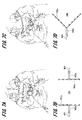
- FIG. 1 It is a schematic diagram which shows the use state of the multi-viewpoint image photographing apparatus which concerns on embodiment of this invention, and is the figure which looked at the use state of the photographing lighting apparatus from the top. It is a transmission side view, a bottom view, and a transmission perspective view of a photographic lighting fixture. It is a simulation figure of the use state in the operating room of a hollow ring type multi-viewpoint imaging apparatus. It is a 6-view view of the hollow ring type multi-viewpoint video imaging apparatus. It is a simulation figure seen from the surgeon's point of view when using the hollow ring type multi-viewpoint imaging apparatus. It is a figure which shows the example of the installation variation (polygon, arc shape) of a multi-viewpoint video imaging apparatus.
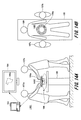
- FIG. 1 It is a figure which shows the example of the installation variation (linear, V-shaped) of a multi-viewpoint video imaging apparatus. It is a figure which shows the example of the installation variation (arch type, composite type) of a multi-viewpoint video imaging apparatus. It is a figure which shows the variation without lighting, and the example of the installation of a photographing instrument. It is a figure which shows the variation without a videographing apparatus, an example of a lighting fixture. It is a block diagram which shows the hardware structure of the multi-viewpoint video imaging apparatus which concerns on embodiment of this invention. It is a block diagram which shows the software function of the image lighting processing apparatus. It is a flowchart which shows the processing flow of the presentation viewpoint gaze point determination processing unit.
- FIG. 1 It is a schematic diagram which shows the use state of the multi-viewpoint image capturing apparatus which concerns on the 1st modification of this invention. It is the schematic which shows the use state of the multi-viewpoint video imaging apparatus which concerns on the 2nd modification of this invention. It is the schematic which shows the LED lighting and the camera of the photographic luminaire which concerns on the 3rd modification of this invention.
- a schematic diagram showing LED lighting and a camera of a shooting lighting fixture, a time chart showing light emission timings of visible light LEDs and infrared LEDs, and an input / output control unit of a video lighting processing device according to a fourth modification of the present invention are provided. It is a block diagram which shows the software function of the infrared image acquisition part. It is the schematic which shows the variation of the suspension arm which concerns on the 5th modification of this invention.
- FIG. 1A is a schematic view showing a usage state of the multi-viewpoint video capturing apparatus 101 according to the embodiment of the present invention
- FIG. 1B is a top view of the usage state of the photographing lighting device 102.
- the multi-viewpoint video imaging device 101 includes a photographing lighting device 102 and a video lighting processing device 103 connected to the photographing lighting device 102. Further, a large screen external monitor 104 is connected to the video illumination processing device 103.
- the operating table 105 lies a patient 106 who has been anesthetized and has an incision in the abdomen.
- the surgeon 107a performs the operation on the patient 106, and the surgeon 107b assists the surgeon 107a in the operation. That is, the surgeon 107a is a surgeon who performs the operation, and the surgeon 107b is an assistant thereof.
- the surgeon 107a and its assistant 107b will be collectively referred to as "surgeon 107".
- the width of the operating table 105 is about 50 cm.
- the incised abdomen, that is, the surgical field 106a has an opening of about 20 cm on the short side and a depth of about 10 cm.
- a hollow ring-shaped imaging luminaire 102 is installed at a position approximately 40 cm from the center of the surgical field 106a and separated upward.
- the imaging luminaire 102 has a plurality of cameras (see FIG. 2B) in a circular or elliptical ring-shaped housing in the example of FIG. 1 so that the surgeons 107a and 107b do not obstruct the visual field when visually recognizing the surgical field 106a. ) And a plurality of lights (see FIG. 2B) are installed toward the surgical field 106a.
- the surgeon 107 looks into the surgical field 106a from the hollow portion of the photographic luminaire 102, inserts his / her hand into a space of about 40 cm under the photographic luminaire 102, and performs the surgical operation.
- the imaging luminaire 102 is suspended from a structure (for example, the ceiling) on the surgical field by, for example, a fixing device 102b, and installed between the surgeon's crown and the surgical field 106a. ..
- the surgeon 107 can visually recognize the surgical field 106a as if looking through the hollow portion of the imaging luminaire 102, but the imaging luminaire 102 is referred to by the image of the surgical field 106a displayed on the external monitor 104. It is also possible to perform surgery and surgical assistance using the space between the surgical field 106a and the surgical field 106a.
- the imaging lighting device 102 used in the multi-viewpoint video imaging device 101 is an instrument arranged within 60 cm directly above the surgical site, which is the area that was this taboo.
- the surgeon 107 can visually recognize the surgical field as if looking into the ring-shaped device installed in the air, while a sufficient working space is secured between the device and the affected area. Therefore, the surgeon 107 can perform the surgical operation without delay. Then, it becomes possible to continue taking a clear surgical field image under a lighting environment that is not obstructed by the surgeon 107's head or shoulder.
- a large number of cameras provided on the imaging luminaire 102 are arranged so as to surround the surgical field 106a. Therefore, it is possible to photograph the surgical field 106a from various directions at the time of surgery. Conventionally, in order to photograph the surgical field 106a from various directions, the camera has been moved in each necessary direction. In the case of the photographing luminaire 102 that constitutes a part of the multi-viewpoint video photographing apparatus 101 according to the embodiment of the present invention, the function of physically moving each camera is not required. By electronically switching the images of a plurality of cameras arranged so as to surround the surgical field 106a in advance as necessary, it becomes possible to easily acquire the images in the imaging direction required by the surgeon 107.
- the image captured by the camera of the photographing lighting device 102 can be viewed on the external monitor 104 installed in the vicinity of the operating table 105.
- the surgeon 107 can see the surgical field 106a with the naked eye and can also check the surgical field 106a on the large screen external monitor 104.
- the multi-viewpoint video imaging device 101 can form an image from a free viewpoint based on images obtained from a plurality of cameras. Therefore, by switching the camera and moving the viewpoint, it is possible to see the surgical field 106a, which is the subject, in three dimensions.
- FIG. 2A is a transmission side view of the photographing luminaire 102
- FIG. 2B is a bottom view of the photographing luminaire 102 as viewed from below
- FIG. 2C is a transmission perspective view of the photographing luminaire 102.
- the photographic lighting fixture 102 has a hollow circular or elliptical ring-shaped housing 102a and a fixing fixture 102b.
- the fixing instrument 102b is provided on the photographing illuminating instrument 102 in order to arrange and fix the housing 102a of the photographing illuminating instrument 102 at a position between the surgical field 106a which is the subject and the crown of the surgeon 107 who is the operator. Has been done.
- the size of the housing 102a is, for example, a circle of 30 to 40 cm. Since the housing 102a has a hollow shape, the surgeon 107 can directly see the surgical field 106a from the hollow portion of the housing 102a with the naked eye.
- the thickness of the housing 102a is preferably as thin as possible so as not to obstruct the view of the surgeon 107. Since the image sensor has been miniaturized in recent years, the housing 102a may be formed of a thin pipe, and the image sensor may be housed in the pipe. Further, the image sensor may be fixed so as to be tied to the outside of a pipe having a thickness that cannot accommodate the image sensor, for example, about 1 cm.
- the surgeon 107 can directly see the surgical field 106a with the naked eye in the operation under direct vision, and can also see it through the external monitor 104.
- the existence of a plurality of means for observing the surgical field 106a leads to a psychological sense of security for the surgeon 107 and contributes to the improvement of safety.
- each camera 201 captures an image that surrounds the surgical field 106a within a range of 10 °.
- the cameras 201 are arranged in the housing 102a at predetermined intervals, and all the cameras 201 are arranged toward the surgical field 106a. Therefore, these cameras 201 are arranged in the housing 102a with different imaging angles with respect to the surgical field 106a, each of which is the subject. However, if the number of cameras 201 increases, the cameras 201 will be arranged side by side without a gap between the cameras 201. Even in such a case, each camera 201 is arranged in the housing 102a with a different imaging angle from the surgical field 106a, which is the subject.
- the photographing luminaire 102 is arranged within 60 cm directly above the surgical field 106a, which is the subject. Therefore, since the cameras 201 arranged in the housing 102a are extremely close to the subject, the shooting angles of all the cameras 201 are inevitably different.
- the number of cameras 201 and lighting 202 may be arbitrarily determined, but ideally, 36 or more cameras 201 are arranged in order to obtain a high-resolution multi-viewpoint image.
- the angle between the cameras 201 is about 10 °
- the switching of the images looks smooth to the surgeon 107 who is viewing the images taken by the cameras 201.
- the angle between the cameras 201 is approximately 15 ° or more, the surgeon 107 who is viewing the image taken by the camera 201 can clearly see the change of the image, and the change of the image may feel uncomfortable. ..
- Each camera 201 includes an interface such as a USB interface, and is connected to the image lighting processing device 103 shown in FIG. 1 via a USB hub 203.
- the light source used for the illumination 202 for example, it is desirable to use a high-intensity LED that emits three primary colors with high color reproducibility.
- LEDs have directivity, so by sealing the housing 102a with an acrylic plate or vinyl chloride plate that has been made opaque by smoke processing or sandblasting, light can be appropriately used as a subject in surgery. It is desirable to disperse toward the surgical field 106a.
- the light source used for the illumination 202 is not limited to the LED, and for example, a krypton sphere may be adopted, or an LED and a krypton sphere may be mixed in order to improve the color reproducibility.
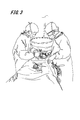
- FIG. 3 is a simulation diagram of a state in which the ring-shaped photographing lighting device 102, which is a basic type, is used in the operating room.
- the surgeon 107 observes the surgical field by looking into the ring formed by the housing 102a of the imaging luminaire 102, and performs the operation using the working space of about 40 cm between the device and the surgical field.
- FIGS. 4A is a top view of the photographic luminaire 102
- FIG. 4B is a bottom view of the photographic luminaire 102
- FIG. 4C is a front view of the photographic luminaire 102
- FIG. 4D is a rear view of the photographic luminaire 102
- FIGS. 4E and 4F It is a side view of the photographic lighting equipment 102.
- the fixation device 102b is provided with a handle 401 for the surgeon 107 to position the imaging lighting device 102 in an appropriate position. ..
- FIG. 5 is a simulation of the surgical field seen from the viewpoint of the surgeon 107. Although the device can be partially seen on the edge of the field of view, there are few parts that block the surgical field, and the surgical operation can be performed comfortably.
- FIG. 6A is a simulation diagram in an operating room using the photographing luminaire 601 according to the modified form example of the first shape
- FIG. 6B is a top view of the photographing luminaire 601 according to the modified form example of the first shape.
- the photographic lighting fixture 601 has a quadrangular housing 601a and a fixing fixture 601b.
- the fixing device 601b is provided with a handle 401 as in the case of the above-mentioned photographing lighting device 102.
- FIG. 6C is a simulation diagram in an operating room using the photographing luminaire 602 according to the modified form example of the second shape
- FIG. 6D is a top view of the photographing luminaire 602 according to the modified form example of the second shape.
- the photographic lighting fixture 602 has an arc-shaped first housing 602a, a first fixing fixture 602b, an arc-shaped second housing 602c, and a second fixing fixture 602d.
- the first fixing device 602b and the second fixing device 602d are each provided with a handle 401, similarly to the above-mentioned photographing lighting device 102.
- FIG. 7A is a simulation diagram in an operating room using the photographing luminaire 701 according to the modified form example of the third shape
- FIG. 7B is a top view of the photographing luminaire 701 according to the modified form example of the third shape.
- the photographic lighting fixture 701 has a linear first housing 701a, a first fixing fixture 701b, a linear second housing 701c, and a second fixing fixture 701d.
- the first fixing device 701b and the second fixing device 701d are each provided with a handle 401, similarly to the above-mentioned photographing lighting device 102.
- FIG. 7C is a simulation diagram in an operating room using the photographing luminaire 702 according to the modified form example of the fourth shape
- FIG. 7D is a top view of the photographing luminaire 702 according to the modified form example of the fourth shape.
- the photographic lighting fixture 702 has a V-shaped housing 702a and a fixing fixture 702b.
- the fixing device 702b is provided with a handle 401 as in the case of the above-mentioned photographing lighting device 102.
- FIG. 8A is a simulation diagram in an operating room using the photographing luminaire 801 according to the modified form example of the fifth shape
- FIG. 8B is a top view of the photographing luminaire 801 according to the modified form example of the fifth shape
- 8C is a side view of the photographing luminaire 801 according to the fifth modified form example.
- the photographic lighting fixture 801 has a housing 801a having an arc shape in the vertical direction and a fixing fixture 801b.
- the fixing device 801b is provided with a handle 401 as in the case of the above-mentioned photographing lighting device 102.
- FIG. 8D is a simulation diagram in an operating room using the photographing luminaire 802 according to the modified form example of the sixth shape
- FIG. 8E is a top view of the photographing luminaire 802 according to the modified form example of the sixth shape
- FIG. 8F is a side view of the photographing luminaire 802 according to the example of the modified form of the sixth shape.
- the photographic lighting fixture 802 has a housing 802a having a portion of an arc in the vertical direction and further having ends of the arc at both ends of the arc, and a fixing fixture 802b.
- the fixing device 801b is provided with a handle 401 as in the case of the above-mentioned photographing lighting device 102.
- a sufficiently large number of camera + light combinations can be arranged in the same manner as the ring type which is the basic type, so that it is possible to create a multi-viewpoint image.
- the C-type x 2 in FIGS. 6C and 6D, and the I-type x 2 in FIGS. 7A and 7B are devices in front of the operator and assistant in order to further reduce visual field obstruction due to the 360 ° ring type. It is devised so that it can be eliminated and a better field of view and workability can be secured. On the other hand, it is undeniable that the quality of multi-view video may deteriorate because the number of cameras and lights that can be placed is reduced in this format at the cost of improving the field of view.
- FIGS. 8A, 8B and 8C show an example of a modified form in which a plurality of cameras and lights are arranged in an arch shape in a narrow range between the operator and the assistant in the vertical direction. It is possible to arrange many cameras + lights in the vertical direction while maintaining the visibility and workability of the surgeon and assistant.
- FIGS. 8D, 8E and 8F show a combination of the C type ⁇ 2 shown in FIG. 6D and the arch type shown in FIGS. 8B and 8C. It is possible to maintain good visual field and workability of the surgeon and assistant, and to arrange a sufficient number of cameras + lights to compose a multi-view visual field image.
- FIG. 9A is a top view of the photographing instrument 901 as a variation without illumination
- FIG. 9B is a schematic view showing a usage state of the photographing instrument 901.
- the photographing apparatus 901 only the plurality of cameras 201 are incorporated in the housing 901a by removing the illumination 202 from the photographing lighting apparatus 102.
- the photographing luminaire 102 is based on a structure in which both a plurality of cameras and a plurality of lights are arranged alternately, for example, but as shown in FIGS. 9A and 9B, there is a variation without illumination. , It is also assumed that it will be designed and used as a photographing device 901 with a plurality of cameras. In this case, since the shadowless lighting installed in the existing operating room can be diverted, it is advantageous in terms of the cost required when introducing the equipment.
- FIG. 10A is a top view of the luminaire 1001 as a variation without a camera
- FIG. 10B is a schematic view showing a usage state of the luminaire 1001.
- the lighting fixture 1001 only the plurality of lightings 202 are incorporated in the housing 1001a, excluding the camera 201 from the photographing lighting fixture 102.
- the photographing lighting fixture 102 is based on a structure in which both a plurality of cameras and a plurality of lights are arranged alternately, for example, but as shown in FIGS. 10A and 10B, there are variations of only lighting. is assumed.
- the conventional shadowless lamp installed above the surgeon 107 blocks the light from the surgeon 107's head and body, and the lighting position needs to be adjusted frequently, but it is installed between the surgeon's crown and the patient.
- This device is a completely shadowless lighting device that is not obstructed by the surgeon's head or body.
- the photographing luminaire 102 of the present invention is a straight line having a finite length as shown in FIGS. 3, 4, 5, 6, 7, and 8 in order to minimize the obstruction of the operator's line of sight. Or, it is formed in various shapes of a finite length curve.
- the thickness of the housing 102a is formed as thin as possible according to the sizes of the plurality of cameras 201 and the lighting 202 to be housed so as not to interfere with the operator.
- the photographing luminaire 102 is formed of a housing made of wire member of finite length, including the linear photographing luminaire 102.
- the shape of the photographing luminaire 102 of the present invention is not limited to those illustrated in FIGS. 3, 4, 5, 6, 7, and 8, but may interfere with the operator's field of view or work. Includes all housing shapes to fulfill the purpose of not being.
- the plurality of cameras and the plurality of lights housed in the housing having a finite length curve shape are all arranged toward the surgical field 106a, which is the subject.
- the photographing illuminating device 102 used in the multi-viewpoint video photographing apparatus 101 of the present invention can take various shapes.
- the housing 102a is preferably made of a lightweight and highly rigid material such as an aluminum alloy, polycarbonate, or carbon.
- the camera 201 and the lighting 202 may be attached to a flexible pipe made of stainless steel or the like used for a water pipe or the like so as to be freely deformable according to the form of the surgical field 106a. Any material such as a flexible pipe that can be freely deformed can also be deformed into the various housing shapes described above.
- FIG. 11 is a block diagram showing a hardware configuration of the multi-viewpoint video capturing apparatus 101 according to the embodiment of the present invention.
- the multi-viewpoint video imaging device 101 includes a camera array unit 1101, an illumination array unit 1102, and a video illumination processing device 103 connected to these.
- the camera array unit 1101 and the illumination array unit 1102 are built in the photographing lighting equipment 102.
- a large screen external monitor 104 is connected to the video illumination processing device 103 through the network 1103.
- the camera array unit 1101 is an aggregate of a plurality of cameras 201 incorporated in the photographing lighting fixture 102 described with reference to FIGS. 1 and 2. These cameras 201 are connected to a serial interface 1128 such as a USB interface included in the video illumination processing device 103.
- the lighting array unit 1102 is an aggregate of a plurality of lighting 202s incorporated in the photographing lighting fixture 102 described with reference to FIGS. 1 and 2.
- the illumination 202 designated by the video illumination processing device 103 is selectively emitted and controlled through the multiplexer 1105 controlled by the microcomputer 1104. Then, it is driven by the current flowing from the power supply voltage node through the current limiting resistor R1106 and the multiplexer 1105.
- the switching control of the multiplexer 1105 is configured so that not only one illumination can be selected, but also a plurality of illuminations can be selected at the same time, including simultaneous lighting of all the illuminations, if necessary. ..
- a microcomputer 1104 is connected between the multiplexer 1105 and the image lighting processing device 103, and the microcomputer 1104 controls the multiplexer 1105 according to the instruction of the image lighting processing device 103.
- the microcomputer 1104 is connected to a serial interface 1128 such as a USB interface included in the video lighting processing device 103.
- the microcomputer 1104 includes a CPU 1108, a ROM 1109, and a RAM 1110 connected to the bus 1107, and a serial interface 1111 (abbreviated as "SI / F" in FIG. 11) such as a USB interface.
- the multiplexer 1105 is connected to the bus 1107 and is controlled by the microcomputer 1104.
- the image lighting processing device 103 which is a well-known computer, includes a CPU 1122, a ROM 1123, a RAM 1124, a display unit 1125, an operation unit 1126, and a non-volatile storage 1127 connected to the bus 1121.
- the CPU 1122 reads out from the non-volatile storage 1127 or the ROM 1123 and executes a software program that realizes the functions of each part included in the video lighting processing device 103.
- the RAM 1124 the images of all the cameras 201 received from the camera array unit 1101 and the variables generated during the arithmetic processing performed in the image illumination processing device 103 are temporarily written.
- the CPU 1122 executes the program recorded in the non-volatile storage 1127 or the ROM 1123, various functions of the video illumination processing device 103 are realized.
- the bus 1121 is connected to a serial interface 1128 such as USB and a NIC (Network Interface Card) 1129 as a communication interface.
- a serial interface 1128 such as USB
- a NIC Network Interface Card
- An external monitor 104 is connected to the NIC 1129 through the network 1103.
- the external monitor 104 includes a well-known computer, which operates a network OS and functions as an external monitor 104 of the image lighting processing device 103.
- the display unit 1125 of the video illumination processing device 103 may be used as it is as a monitor, but generally, the connection cable between the display unit 1125 and the video illumination processing device 103 has a length limitation, so that the external monitor 104 and the network It is preferable to connect at 1103. Then, when the video illumination processing device 103 is constructed as a network moving image server, a plurality of external monitors 104 can be easily connected, so that the same desired video can be displayed on different monitors at the same time. Therefore, even if the external monitor 104 breaks down due to some accident, it is possible to prevent a surgical accident by operating the spare external monitor 104 as it is.
- FIG. 12 is a block diagram showing a software function of the video lighting processing device 103.
- the image lighting processing device 103 includes an input / output control unit 1201, a camera calibration processing unit 1202, a presentation viewpoint gazing point determination processing unit 1204, an image processing unit 1205, a lighting determination processing unit 1206, and a display unit 1125.
- the camera array unit 1101 is composed of a large number of cameras 1 to N embedded in the imaging lighting device 102 and arranged so as to surround the periphery of the surgical field 106a, and photographs the surgical field 106a from various directions during surgery. do.
- the lighting array unit 1102 is embedded in the photographing lighting device 102 together with the camera 201 and arranged so as to surround the periphery of the surgical field 106a, and usually equal to the number of cameras 201 in the camera array unit 1101. Consists of N. Then, the illumination 202 adjacent to the camera 201 selected by the presentation viewpoint gazing point determination processing unit 1204 is controlled to emit light. Also, if necessary, all lighting is controlled to emit light all at once.
- the input / output control unit 1201 receives the video data obtained from the camera array unit 1101 and also gives the illumination array unit 1102 control information for switching the illuminations 1 to N.
- the input / output control unit 1201 and the camera array unit 1101 are connected by a bidirectional serial interface 1128. All cameras 201 of the camera array unit 1101 transmit video data to the input / output control unit 1201.
- the input / output control unit 1201 and the lighting array unit 1102 are connected by a USB interface.
- the input / output control unit 1201 receives a lighting command from the lighting determination processing unit 1206 described later, the input / output control unit 1201 transmits a light emission command to the lighting 202 designated by the lighting determination processing unit 1206 in accordance with the lighting command.
- the microcomputer 1104 that receives the light emission command from the input / output control unit 1201 in the illumination array unit 1102 controls the multiplexer 1105 to control the light emission of the designated illumination 202.
- the input / output control unit 1201 and the camera calibration processing unit 1202 are connected by a serial interface.
- the camera calibration processing unit 1202 estimates camera parameters such as the positions, postures, and focal lengths of the cameras 1 to N constituting the camera array unit 1101 based on the image information.
- the camera 201 embedded in the photographing lighting fixture 102 is composed of an angle of view in which a common area is observed in images of adjacent cameras 201. Then, the camera parameters such as the position, posture, and focal length of each camera 201 with respect to the surgical field 106a, which is the subject, are estimated from the correspondence of the common observation areas.
- Partial image data of surgical instruments such as scalpels, tweezers, and scissors and observation position coordinate information cut out from the multi-viewpoint video data are stored in the RAM 1124 or the non-volatile storage 1127 as the gazing point article image and the gazing point coordinates 1207. ..
- the cut-out partial image data of the operator's hand and the observation position coordinate information are stored in the RAM 1124 or the non-volatile storage 1127 as the gazing point article image and the gazing point coordinate 1207.
- the reason for preparing multiple multi-viewpoint video data of the operator's fingers is that the fingers freely change their shapes, so in order to increase the probability of image matching, multiple multi-viewpoint video data are used as the gaze-point article video and This is because it is necessary to prepare it as the gazing point coordinate 1207.
- the gazing point is a triangulation based on camera parameters for a representative point (two-dimensional point) of a partial region of the subject that the operator is paying attention to in the multi-viewpoint image data obtained from the camera array unit 1101. Refers to a three-dimensional point estimated by applying.
- the input / output control unit 1201 and the presentation viewpoint gaze point determination processing unit 1204 are connected by a serial interface.
- the presentation viewpoint gazing point determination processing unit 1204 refers to the gazing point article image and the gazing point coordinate 1207, and selects the part of the subject that the surgeon 107 wants to see from all the images of the cameras 201 received from the input / output control unit 1201. Detect and estimate its two-dimensional position coordinates.
- the presentation viewpoint gaze point determination processing unit 1204 further determines the presentation viewpoint, which is the viewpoint at which the gaze point can be photographed most appropriately.
- the presentation viewpoint gaze determination processing unit 1204 performs this presentation viewpoint determination process by taking into consideration the reflection of the surgeon 107's hand and surgical instrument on the captured image, and then taking a picture from a direction suitable for the surgeon 107's observation. Is selected from the cameras 1 to N constituting the camera array unit 1101.
- the camera calibration processing unit 1202 and the presentation viewpoint gaze point determination processing unit 1204 are connected by a serial interface.
- the presentation viewpoint gazing point determination processing unit 1204 is a subject that the assistant 107b of the surgeon 107a wants to see from the two-dimensional position coordinates estimated as camera parameters such as the position, orientation, and focal length of the camera 201 received from the camera calibration processing unit 1202. That is, the three-dimensional coordinates of the gazing point are calculated based on the stereo vision.
- the presented viewing point gazing point determination processing unit 1204 identifies the camera 201 that clearly captures the gazing point. The above is the determination process of the presentation viewpoint by the presentation viewpoint gaze determination processing unit 1204.
- the illumination determination processing unit 1206 basically generates information for on-controlling the illumination 202 arranged on both sides of the camera 201, which is specified by the presentation viewpoint gaze determination processing unit 1204 to clearly capture the gaze point. do. If a specific camera 201 is not specified, all the lights are turned on.
- the image processing unit 1205 is an interface for outputting the camera 201 that clearly captures the gazing point specified by the presentation viewpoint gazing point determination processing unit 1204 to the display unit 1125, the external monitor 104, or the like.
- the image processing unit 1205 supplies the multi-viewpoint image to the display unit 1125 provided in the operating room, and also provides the multi-viewpoint image to the external monitor 104a via the network 1103.
- the external monitor 104a can display the images of the plurality of cameras 201 at the same time. Among them, for example, one camera image that is closest to the line of sight of the surgeon 107a and captures a clear image that is not obstructed by the surgeon, assistant's hand, or surgical instrument is enlarged and displayed as the main image, and all the participating members Can be shared.
- the external monitor 104b presents the surgeon 107a with an image from an angle different from its own line of sight, or, for example, the external monitor 104c presents image information other than white light captured by near infrared rays.
- It is a display device that can present image information other than direct-view video to the operator.
- the presentation viewpoint gazing point determination processing unit 1204 and / or the image processing unit 1205 is used so that the viewer or the surgeon 107 can view the multi-viewpoint image intuitively or with a simple operation.
- the function of manually selecting the camera 201 from the operation unit may be added.
- FIG. 13 is a flowchart showing a processing flow of the presentation viewpoint gazing point determination processing unit 1204.
- the presentation viewpoint gazing point determination processing unit 1204 sets the position of the camera 201 and the person area volume ( The three-dimensional coordinate information of the position of the hand of the surgeon 107), the position of the gazing point, and the position of the instrument area is acquired (S1302).
- the presentation viewpoint gazing point determination processing unit 1204 determines whether or not the surgeon 107 has a hand between the camera position and the gazing point position based on the three-dimensional coordinate information of the gazing point (S1303). If it is determined in step S1303 that the surgeon 107's hand is between the camera position and the gazing point position (YES in S1303), a camera that does not have the surgeon 107's hand is searched between the camera position and the gazing point position.
- step S1303 When it is determined in step S1303 that there is no hand of the surgeon 107 between the camera position and the gazing point position (NO in S1303), the presentation viewpoint gazing point determination processing unit 1204 subsequently determines the three-dimensional coordinate information of the gazing point. Based on the above, it is determined whether or not there is a surgical instrument between the camera position and the gazing point position (S1304).
- step S1304 determines in step S1304 that there is a surgical instrument between the camera position and the gazing point position (YES in S1304), the surgical instrument exists between the camera position and the gazing point position. Do not search for cameras. If the presentation viewpoint gazing point determination processing unit 1204 determines that there is no surgical instrument between the camera position and the gazing point position in step S1304 (NO in S1304), the used camera address information and zoom in the cameras 1 to N. A value is output (S1306), and a series of processes is completed (S1307).
- the multi-viewpoint imaging apparatus 101 has live magnified information from a viewpoint different from that of the naked eye, in addition to direct vision with the naked eye, in contrast to surgery that has been performed only by direct vision with the naked eye. Is presented to surgeon 107.
- the imaging luminaire 102 equipped with the camera 201 and the luminaire 202 is located between the surgeon 107 and the patient 106, and unlike conventional surgical luminaires, the light of the luminaire is directed by the heads of the surgeons 107a, 107b. It will not be blocked. Therefore, the surgical field 106a and the vicinity of the gazing point are always brightly illuminated by the illumination 202, and the visibility is remarkably improved.
- the surgical field 106a and the gaze point area enlarged and displayed by the multi-viewpoint imaging device 101 are multi-viewpoint images
- the surgical field 106a and the gaze point area can be confirmed three-dimensionally by moving the viewpoint. Can be done.
- the presentation viewpoint gazing point determination processing unit 1204 identifies the gazing point 3D coordinate information in the multi-viewpoint image being photographed from the gazing point 3D coordinate information stored in advance in the gazing point article image and the gazing point coordinate 1207. By doing so, appropriate viewpoint switching can be realized centering on the object of interest (for example, the tip of a scalpel).
- the multi-viewpoint imaging device 101 can significantly improve the certainty and safety of surgery due to the above features.
- the presentation viewpoint can be moved by manual operation through the operation unit 1126.
- the viewpoint is switched around an object other than the object of interest (for example, the tip of a scalpel).
- the observation position of the object of interest for example, the tip of a scalpel
- FIG. 14 is a schematic view showing a usage state of the multi-viewpoint video capturing apparatus 1401 according to the first modification of the present invention.
- the difference between the multi-viewpoint imaging device 1401 shown in FIG. 14 and the multi-viewpoint imaging device 101 shown in FIG. 1 is that the imaging lighting device 1402 is downsized and placed directly on the surgical field 106a of the patient 106. be.
- a hollow ring in which the camera array unit 1101 and the illumination array unit 1102 are arranged is arranged between the patient 106 and the surgeon 107, for example, at a position about 30 cm away from the patient 106. It is attached to the frame.
- the surgeon 107 can perform the operation while visually observing the surgical field 106a.
- the head of the surgeon 107 can be shadowed by the illumination to eliminate the imperfections in the imaging, but the problem is that the frame with the hollow ring obstructs the surgeon 107's field of view. There is.
- a hollow ring in which the camera array unit 1101 and the illumination array unit 1102 are arranged is placed on the peripheral edge of the surgical field 106a of the patient 106. It is installed like this. In this case as well, the surgeon 107 can perform the operation visually. With this surgical procedure, the operation can be performed in the same state as a normal surgical operation, so that the surgeon 107 has less hindrance to the work as compared with the imaging lighting device 102 of FIG. However, since the imaging lighting instrument 1402 comes into contact with the patient 106, the hands of the surgeons 107a and 107b and the surgical instrument may be in the shadow of the illumination.
- FIG. 15 is a schematic view showing a usage state of the multi-viewpoint video capturing apparatus 1501 according to the second modification of the present invention.
- the difference between the multi-viewpoint image capturing device 1501 shown in FIG. 15 and the multi-viewpoint image capturing device 101 shown in FIG. 1 and the multi-viewpoint image capturing device 1401 shown in FIG. It is a point that it is further miniaturized than the imaging luminaire 1402 according to the above, and is directly inserted into the surgical field 106a of the patient 106.
- the imaging lighting device 1502 shown in FIG. 15 is an example in which a hollow ring in which the camera array unit 1101 and the lighting array unit 1102 are arranged is inserted into the abdominal cavity of the patient 106 and installed so as to look down on the surgical site from the upper part of the abdominal cavity. According to this surgical procedure, the surgeons 107a and 107b can perform the operation while viewing the captured image, and the camera 201 can capture the entire abdominal cavity. However, the hollow ring in which the camera 201 and the illumination array unit 1102 are arranged must be taken in and out from the insertion port provided in the abdomen of the patient 106.
- Imaging lighting device 1601 for simultaneously photographing the blood vessels of the surgical field 106a of the patient 106 using an infrared LED 1605 and a cold mirror 1606 or a hot mirror When an image of a blood vessel is displayed on an external monitor 104 together with a visible light image during a surgical operation, it is possible to prevent the occurrence of a medical accident that damages the blood vessel, and further improvement in safety can be expected.
- FIG. 16 is a schematic view showing a photographing luminaire 1601 according to a third modification of the present invention, an LED lighting 1602 incorporated in the photographing illuminating device 1601, and a camera unit 1603.
- the LED illumination 1602 has a visible light LED 1604 and an infrared LED 1605.
- the visible light LED 1604 and the infrared LED 1605 are continuously emitting light at the same time.
- the camera unit 1603 includes a cold mirror 1606 installed at an angle of 45 ° on the optical axis, a first camera 1007 installed at a position passing through the cold mirror 1606 on the optical axis, and a cold mirror 1606 on the optical axis. It has a second camera 1008 installed at orthogonal positions.
- the cold mirror 1606 transmits near-infrared light and reflects visible light. Therefore, the first camera 1007 captures an infrared image, and the second camera 1008 captures a visible light image. Even if a hot mirror that transmits visible light and reflects near-infrared light is installed instead of the cold mirror 1606, the first camera 1007 captures a visible light image and the second camera 1008 captures an infrared image. be able to. In either case, since the visible light image and the infrared image can be simultaneously captured from the incoming light, the visible light image and the infrared image can be simultaneously displayed on the display unit 1125 and the external monitor 104.
- FIG. 17A is a schematic view showing the LED lighting 1602 and the camera 201 of the photographing lighting fixture according to the fourth modification of the present invention
- FIG. 17B is a time chart showing the light emission timings of the visible light LED 1604 and the infrared LED 1605.
- FIG. 17C is a block diagram showing a software function of the infrared image acquisition unit 1702 provided in the input / output control unit 1201 of the image illumination processing device 103.
- the camera 201 is a general image sensor, and does not have a special structure as in the third modification. Instead, the camera 201 outputs a frame timing pulse.
- the frame timing pulse is input to the light emission timing control unit 1701.
- the light emission timing control unit 1701 synchronizes the light emission timings of the visible light LED 1604 and the infrared LED 1605 with the frame timing pulse included in the video data output by the camera 201, and emits light from the visible light LED 1604 and the infrared LED 1605 at the timing shown in FIG. 17B. To control. That is, the light emission timing control unit 1701 emits only the visible light LED 1604 at the time of the first frame timing t1711, emits only the infrared LED 1605 at the time of the second frame timing t1712, and emits light only with the visible light LED 1604 at the time of the third frame timing t1713. Turn off both infrared LEDs 1605. This operation is repeated.
- the infrared LED lighting shooting video data obtained at the second frame timing and the infrared LED turning off shooting video data obtained at the third frame timing are formed in the input / output control unit 1201 of the video lighting processing device 103. It is input to the infrared image acquisition unit 1702 (see FIG. 17C). Further, as shown in FIG. 17C, the infrared image acquisition unit 1702 has an infrared LED on photography image buffer 1703 that holds the infrared LED on photography image data and an infrared LED off photography image buffer 1704 that holds the infrared LED off photography image data. And an adder 1705.
- the infrared LED on shooting video data output from the infrared LED on shooting video buffer 1703 and the infrared LED off shooting video data output from the infrared LED off shooting video buffer 1704 are input to the adder 1705.
- the adder 1705 subtracts the infrared LED off shooting video data from the infrared LED on shooting video data for each pixel. Then, the infrared LED off shooting image data, that is, the noise component due to visible light, which is included in the infrared LED on shooting image data, is subtracted.
- the frame rate is reduced to 1/3 as compared with the third modification, the infrared image can be acquired by using the general-purpose camera 201 as it is. Therefore, as in the case of the third modification, it is possible to prevent the occurrence of a medical accident that damages a blood vessel in a surgical operation, and improvement in safety can be expected.
- the video data of the specific wavelength spectrum can be acquired. Becomes possible.
- the video lighting processing device 103 a general personal computer can be used as it is. Therefore, not only the multi-viewpoint image of the surgical field 106a by visible light and the multi-viewpoint image of blood vessels by infrared light are displayed on the display unit 1125 and the external monitor 104, but also the information output by the external device is displayed at the same time. It also becomes possible.
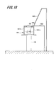
- FIG. 18 is a schematic view showing a variation of the fixing device 102b according to the fifth modification of the present invention.
- the fixing device 102b shown in FIG. 1 is provided to maintain the imaging lighting device 102 floating from the surgical field 106a.
- the fixture 102b has a structure suspended from the ceiling of an operating room (not shown) so as not to interfere with the operation of the surgeon 107.
- the legs 1801a and 1801b extending directly below the photographing luminaire 102 and the extension arm 1802 extending directly beside the photographing luminaire 102 It is also conceivable to provide. Further, an extension arm 1803 extending diagonally upward of the photographing luminaire 102 can be provided. As described above, various variations can be considered as the form of the fixing instrument for maintaining the state in which the imaging lighting instrument 102 is floated from the surgical field 106a.
- the multi-viewpoint imaging device 101 aims to provide the surgeon 107 in an integrated manner with a wide variety of information essential for surgery, such as a cockpit of an airplane.
- preoperative simulation information such as preoperative CT images, MRI images and 3D reconstructed images, and appropriate infrared images of the main part are appropriate.
- Navigation information such as vascular travel can be displayed on the external monitor 104 in an appropriate layout according to the progress of surgery.
- patient 106 vital information acquired in real time such as blood pressure, pulse, electrocardiogram, and electroencephalogram of patient 106
- medical safety information such as surgical procedure / surgical members
- medical cost information such as equipment used should be displayed as shared information. It may be.
- the multi-viewpoint imaging device 101 is expected to play a major role in enhancing the safety of surgery.
- Various information such as live magnified information, infrared information, preoperative radiographic image information, 3D simulation information, and medical safety information are displayed to the surgeon 107 for surgery that has been performed only by direct vision with the naked eye. This makes it possible to significantly improve the safety of surgery.
- the surgical light is an indispensable equipment in all operating rooms, but the illuminated camera device used in the embodiment of the present invention can play a role as a more compact surgical light.
- the illuminated camera device used in the present invention a large-scale surgical light equipment is no longer required in the operating room, and it is said that there are about 20,000 operating rooms throughout Japan. There is also the possibility of becoming.
- the multi-viewpoint imaging device 101 can be said to be a completely new surgical support system, and can be said to have the potential to completely change the scenery of operating rooms in the world.
- this multi-viewpoint imaging device is supposed to be used mainly in surgical operations targeting living organisms, but it is a clear lighting environment that is not obscured by the operator's head or body.
- the feature of this device which enables unobstructed surgical field imaging, is that it is more veterinary for animals in fields such as pathological anatomy, judicial anatomy, surgical anatomy, and educational anatomy for corpses. It is also effectively applied in the surgical scene.
- the above-described embodiment describes in detail and concretely the configurations of the apparatus and the system in order to explain the present invention in an easy-to-understand manner, and is not necessarily limited to those including all the described configurations. Further, it is possible to replace a part of the configuration of one embodiment with the configuration of another embodiment, and further, it is possible to add the configuration of another embodiment to the configuration of one embodiment. It is also possible to add / delete / replace a part of the configuration of each embodiment with another configuration.
- Multi-viewpoint imaging device 102 ... Imaging lighting equipment, 102a ... Housing, 102b ... Fixed instrument, 103 ... Image lighting processing device, 104 ... External monitor, 105 ... Operating table, 106 ... Patient, 106a ... Surgical field , 107 ... Surgeon, 201 ... Camera, 202 ... Lighting, 203 ... USB Hub, 401 ... Handle, 601 ... Shooting Lighting Equipment, 601a ... Housing, 601b ... Fixing Equipment, 602 ... Shooting Lighting Equipment, 602a ... First Housing , 602b ... First fixing device, 602c ... Second housing, 602d ... Second fixing device, 701 ... Shooting lighting device, 701a ...
- Multi-viewpoint video shooting device 1502 ... Shooting lighting equipment, 1601 ... Shooting lighting equipment, 1602 ... LED lighting, 1603 ... Camera unit, 1604 ... Visible light LED, 1605 ... Infrared LED, 1606 ... Cold mirror, 1701 ... Light emission timing control unit, 1702 ... Infrared image acquisition unit, 1703 ... Infrared LED lighting Shooting video buffer, 1704 ... Infrared LED off Shooting video buffer, 1705 ... Adder, 1801a ... Leg, 1802, 1803 ... Extension arm
Landscapes
- Health & Medical Sciences (AREA)
- Life Sciences & Earth Sciences (AREA)
- Surgery (AREA)
- Engineering & Computer Science (AREA)
- Nuclear Medicine, Radiotherapy & Molecular Imaging (AREA)
- Heart & Thoracic Surgery (AREA)
- Molecular Biology (AREA)
- Oral & Maxillofacial Surgery (AREA)
- Pathology (AREA)
- Veterinary Medicine (AREA)
- Medical Informatics (AREA)
- Public Health (AREA)
- Biomedical Technology (AREA)
- General Health & Medical Sciences (AREA)
- Animal Behavior & Ethology (AREA)
- Gynecology & Obstetrics (AREA)
- Radiology & Medical Imaging (AREA)
- Computer Vision & Pattern Recognition (AREA)
- General Physics & Mathematics (AREA)
- Physics & Mathematics (AREA)
- Theoretical Computer Science (AREA)
- Studio Devices (AREA)
- Endoscopes (AREA)
Priority Applications (2)
| Application Number | Priority Date | Filing Date | Title |
|---|---|---|---|
| JP2022510590A JP7633704B2 (ja) | 2020-03-26 | 2021-03-24 | 多視点映像撮影装置 |
| US17/906,833 US12364569B2 (en) | 2020-03-26 | 2021-03-24 | Multi-viewpoint video capturing device |
Applications Claiming Priority (2)
| Application Number | Priority Date | Filing Date | Title |
|---|---|---|---|
| JP2020-055921 | 2020-03-26 | ||
| JP2020055921 | 2020-03-26 |
Publications (1)
| Publication Number | Publication Date |
|---|---|
| WO2021193697A1 true WO2021193697A1 (ja) | 2021-09-30 |
Family
ID=77890442
Family Applications (1)
| Application Number | Title | Priority Date | Filing Date |
|---|---|---|---|
| PCT/JP2021/012162 Ceased WO2021193697A1 (ja) | 2020-03-26 | 2021-03-24 | 多視点映像撮影装置 |
Country Status (3)
| Country | Link |
|---|---|
| US (1) | US12364569B2 (https=) |
| JP (1) | JP7633704B2 (https=) |
| WO (1) | WO2021193697A1 (https=) |
Cited By (2)
| Publication number | Priority date | Publication date | Assignee | Title |
|---|---|---|---|---|
| CN114205575A (zh) * | 2021-12-23 | 2022-03-18 | 桑瑞思医疗科技有限公司 | 手术视频三维重构方法、装置、设备及存储介质 |
| JPWO2024128212A1 (https=) * | 2022-12-15 | 2024-06-20 |
Citations (2)
| Publication number | Priority date | Publication date | Assignee | Title |
|---|---|---|---|---|
| US20110264078A1 (en) * | 2010-04-23 | 2011-10-27 | Lipow Kenneth I | Ring form surgical effector |
| JP2015521913A (ja) * | 2012-06-27 | 2015-08-03 | キャンプレックス インコーポレイテッド | 手術可視化システム |
Family Cites Families (3)
| Publication number | Priority date | Publication date | Assignee | Title |
|---|---|---|---|---|
| JP2017068810A (ja) | 2015-10-04 | 2017-04-06 | 国立大学法人金沢大学 | 静脈可視化システム、静脈可視化方法、及び、静脈可視化プログラム |
| JP2019003320A (ja) | 2017-06-13 | 2019-01-10 | キヤノン株式会社 | 画像生成装置、画像生成方法、及びプログラム |
| JP6933935B2 (ja) | 2017-09-04 | 2021-09-08 | 大樹 梶田 | カメラシステム |
-
2021
- 2021-03-24 WO PCT/JP2021/012162 patent/WO2021193697A1/ja not_active Ceased
- 2021-03-24 US US17/906,833 patent/US12364569B2/en active Active
- 2021-03-24 JP JP2022510590A patent/JP7633704B2/ja active Active
Patent Citations (2)
| Publication number | Priority date | Publication date | Assignee | Title |
|---|---|---|---|---|
| US20110264078A1 (en) * | 2010-04-23 | 2011-10-27 | Lipow Kenneth I | Ring form surgical effector |
| JP2015521913A (ja) * | 2012-06-27 | 2015-08-03 | キャンプレックス インコーポレイテッド | 手術可視化システム |
Cited By (3)
| Publication number | Priority date | Publication date | Assignee | Title |
|---|---|---|---|---|
| CN114205575A (zh) * | 2021-12-23 | 2022-03-18 | 桑瑞思医疗科技有限公司 | 手术视频三维重构方法、装置、设备及存储介质 |
| JPWO2024128212A1 (https=) * | 2022-12-15 | 2024-06-20 | ||
| WO2024128212A1 (ja) * | 2022-12-15 | 2024-06-20 | 国立大学法人 東京大学 | 注視点に基づく情報を出力する情報処理装置、注視点に基づく情報を出力する情報処理方法及びプログラム |
Also Published As
| Publication number | Publication date |
|---|---|
| JPWO2021193697A1 (https=) | 2021-09-30 |
| US20230363852A1 (en) | 2023-11-16 |
| JP7633704B2 (ja) | 2025-02-20 |
| US12364569B2 (en) | 2025-07-22 |
Similar Documents
| Publication | Publication Date | Title |
|---|---|---|
| US20230255446A1 (en) | Surgical visualization systems and displays | |
| US10197803B2 (en) | Augmented reality glasses for medical applications and corresponding augmented reality system | |
| US20220054223A1 (en) | Surgical visualization systems and displays | |
| US11819273B2 (en) | Augmented and extended reality glasses for use in surgery visualization and telesurgery | |
| US11154378B2 (en) | Surgical visualization systems and displays | |
| US11464582B1 (en) | Surgery guidance system | |
| TWI745307B (zh) | 強化實境之外科導航 | |
| JP2022091159A (ja) | 物体の三次元モデルを形成するための1つ又は複数の光度エッジの生成 | |
| EP3146715B1 (en) | Systems and methods for mediated-reality surgical visualization | |
| CN104939925B (zh) | 基于三角测量的深处和表面可视化 | |
| Gavaghan et al. | A portable image overlay projection device for computer-aided open liver surgery | |
| EP3725254A2 (en) | Microsurgery system with a robotic arm controlled by a head-mounted display | |
| US20100245557A1 (en) | Injection of secondary images into microscope viewing fields | |
| CN108430306A (zh) | 用于使用激光散斑对比度成像快速检查脉管系统和微粒流的系统和方法 | |
| CN113164013B (zh) | 图像引导外科手术中的近红外信息与彩色图像的组合 | |
| JP7633704B2 (ja) | 多視点映像撮影装置 | |
| WO2024188159A1 (zh) | 用于内窥镜系统的成像及显示方法和内窥镜系统 | |
| WO2024188160A1 (zh) | 用于内窥镜系统的成像及显示方法和内窥镜系统 | |
| Southern et al. | Video microsurgery: early experience with an alternative operating magnification system | |
| Muratore et al. | Image display in endoscopic surgery | |
| US20220039904A1 (en) | Jig assembled on stereoscopic surgical microscope for applying augmented reality techniques to surgical procedures | |
| CN113164134A (zh) | X射线成像引导 | |
| JP2025173895A (ja) | 医用装置及び制御方法 | |
| WO2016080118A1 (ja) | 内視鏡システム |
Legal Events
| Date | Code | Title | Description |
|---|---|---|---|
| 121 | Ep: the epo has been informed by wipo that ep was designated in this application |
Ref document number: 21776343 Country of ref document: EP Kind code of ref document: A1 |
|
| DPE1 | Request for preliminary examination filed after expiration of 19th month from priority date (pct application filed from 20040101) | ||
| ENP | Entry into the national phase |
Ref document number: 2022510590 Country of ref document: JP Kind code of ref document: A |
|
| NENP | Non-entry into the national phase |
Ref country code: DE |
|
| 122 | Ep: pct application non-entry in european phase |
Ref document number: 21776343 Country of ref document: EP Kind code of ref document: A1 |