WO2021193697A1 - 多視点映像撮影装置 - Google Patents
多視点映像撮影装置 Download PDFInfo
- Publication number
- WO2021193697A1 WO2021193697A1 PCT/JP2021/012162 JP2021012162W WO2021193697A1 WO 2021193697 A1 WO2021193697 A1 WO 2021193697A1 JP 2021012162 W JP2021012162 W JP 2021012162W WO 2021193697 A1 WO2021193697 A1 WO 2021193697A1
- Authority
- WO
- WIPO (PCT)
- Prior art keywords
- viewpoint
- camera
- surgeon
- cameras
- image
- Prior art date
Links
- 238000012545 processing Methods 0.000 claims description 77
- 238000003384 imaging method Methods 0.000 claims description 68
- 230000036544 posture Effects 0.000 claims description 3
- 238000001356 surgical procedure Methods 0.000 abstract description 58
- 238000005286 illumination Methods 0.000 abstract description 47
- 230000000007 visual effect Effects 0.000 abstract description 8
- 230000010365 information processing Effects 0.000 abstract description 2
- 210000003128 head Anatomy 0.000 description 24
- 230000004048 modification Effects 0.000 description 18
- 238000012986 modification Methods 0.000 description 18
- 238000010586 diagram Methods 0.000 description 16
- 238000000034 method Methods 0.000 description 14
- 238000004088 simulation Methods 0.000 description 12
- 210000004204 blood vessel Anatomy 0.000 description 8
- 238000005516 engineering process Methods 0.000 description 8
- 230000007246 mechanism Effects 0.000 description 7
- 230000006872 improvement Effects 0.000 description 6
- 210000000683 abdominal cavity Anatomy 0.000 description 5
- 210000003484 anatomy Anatomy 0.000 description 5
- 210000001015 abdomen Anatomy 0.000 description 4
- 230000005540 biological transmission Effects 0.000 description 4
- 230000008859 change Effects 0.000 description 4
- 238000009434 installation Methods 0.000 description 4
- 230000008569 process Effects 0.000 description 4
- 238000002357 laparoscopic surgery Methods 0.000 description 3
- 239000000463 material Substances 0.000 description 3
- 230000003287 optical effect Effects 0.000 description 3
- 230000002093 peripheral effect Effects 0.000 description 3
- 125000002066 L-histidyl group Chemical group [H]N1C([H])=NC(C([H])([H])[C@](C(=O)[*])([H])N([H])[H])=C1[H] 0.000 description 2
- 230000002708 enhancing effect Effects 0.000 description 2
- 229910052743 krypton Inorganic materials 0.000 description 2
- DNNSSWSSYDEUBZ-UHFFFAOYSA-N krypton atom Chemical compound [Kr] DNNSSWSSYDEUBZ-UHFFFAOYSA-N 0.000 description 2
- 230000033001 locomotion Effects 0.000 description 2
- 238000001228 spectrum Methods 0.000 description 2
- 229910000838 Al alloy Inorganic materials 0.000 description 1
- OKTJSMMVPCPJKN-UHFFFAOYSA-N Carbon Chemical compound [C] OKTJSMMVPCPJKN-UHFFFAOYSA-N 0.000 description 1
- 241001465754 Metazoa Species 0.000 description 1
- 206010028980 Neoplasm Diseases 0.000 description 1
- 240000007594 Oryza sativa Species 0.000 description 1
- 235000007164 Oryza sativa Nutrition 0.000 description 1
- BZHJMEDXRYGGRV-UHFFFAOYSA-N Vinyl chloride Chemical compound ClC=C BZHJMEDXRYGGRV-UHFFFAOYSA-N 0.000 description 1
- 206010047571 Visual impairment Diseases 0.000 description 1
- NIXOWILDQLNWCW-UHFFFAOYSA-N acrylic acid group Chemical group C(C=C)(=O)O NIXOWILDQLNWCW-UHFFFAOYSA-N 0.000 description 1
- 230000002457 bidirectional effect Effects 0.000 description 1
- 230000036772 blood pressure Effects 0.000 description 1
- 201000011510 cancer Diseases 0.000 description 1
- 229910052799 carbon Inorganic materials 0.000 description 1
- 239000003086 colorant Substances 0.000 description 1
- 238000004891 communication Methods 0.000 description 1
- 239000002131 composite material Substances 0.000 description 1
- 239000012141 concentrate Substances 0.000 description 1
- 238000011161 development Methods 0.000 description 1
- 230000000694 effects Effects 0.000 description 1
- 238000002674 endoscopic surgery Methods 0.000 description 1
- 230000010006 flight Effects 0.000 description 1
- 238000007667 floating Methods 0.000 description 1
- 239000007850 fluorescent dye Substances 0.000 description 1
- 239000011521 glass Substances 0.000 description 1
- 238000003780 insertion Methods 0.000 description 1
- 230000037431 insertion Effects 0.000 description 1
- 230000001788 irregular Effects 0.000 description 1
- 238000002350 laparotomy Methods 0.000 description 1
- 230000003902 lesion Effects 0.000 description 1
- 210000001165 lymph node Anatomy 0.000 description 1
- 238000012544 monitoring process Methods 0.000 description 1
- 230000001575 pathological effect Effects 0.000 description 1
- 239000004417 polycarbonate Substances 0.000 description 1
- 229920000515 polycarbonate Polymers 0.000 description 1
- 238000004321 preservation Methods 0.000 description 1
- 235000009566 rice Nutrition 0.000 description 1
- 238000005488 sandblasting Methods 0.000 description 1
- 238000007789 sealing Methods 0.000 description 1
- 239000000779 smoke Substances 0.000 description 1
- 239000010935 stainless steel Substances 0.000 description 1
- 229910001220 stainless steel Inorganic materials 0.000 description 1
- 239000000725 suspension Substances 0.000 description 1
- 230000001360 synchronised effect Effects 0.000 description 1
- 230000008685 targeting Effects 0.000 description 1
- 230000002792 vascular Effects 0.000 description 1
- 208000029257 vision disease Diseases 0.000 description 1
- 230000004393 visual impairment Effects 0.000 description 1
- 208000008918 voyeurism Diseases 0.000 description 1
- XLYOFNOQVPJJNP-UHFFFAOYSA-N water Substances O XLYOFNOQVPJJNP-UHFFFAOYSA-N 0.000 description 1
- PICXIOQBANWBIZ-UHFFFAOYSA-N zinc;1-oxidopyridine-2-thione Chemical class [Zn+2].[O-]N1C=CC=CC1=S.[O-]N1C=CC=CC1=S PICXIOQBANWBIZ-UHFFFAOYSA-N 0.000 description 1
Images


Classifications
-
- A—HUMAN NECESSITIES
- A61—MEDICAL OR VETERINARY SCIENCE; HYGIENE
- A61B—DIAGNOSIS; SURGERY; IDENTIFICATION
- A61B90/00—Instruments, implements or accessories specially adapted for surgery or diagnosis and not covered by any of the groups A61B1/00 - A61B50/00, e.g. for luxation treatment or for protecting wound edges
- A61B90/36—Image-producing devices or illumination devices not otherwise provided for
- A61B90/37—Surgical systems with images on a monitor during operation
-
- A—HUMAN NECESSITIES
- A61—MEDICAL OR VETERINARY SCIENCE; HYGIENE
- A61B—DIAGNOSIS; SURGERY; IDENTIFICATION
- A61B90/00—Instruments, implements or accessories specially adapted for surgery or diagnosis and not covered by any of the groups A61B1/00 - A61B50/00, e.g. for luxation treatment or for protecting wound edges
- A61B90/20—Surgical microscopes characterised by non-optical aspects
- A61B90/25—Supports therefor
-
- A—HUMAN NECESSITIES
- A61—MEDICAL OR VETERINARY SCIENCE; HYGIENE
- A61B—DIAGNOSIS; SURGERY; IDENTIFICATION
- A61B90/00—Instruments, implements or accessories specially adapted for surgery or diagnosis and not covered by any of the groups A61B1/00 - A61B50/00, e.g. for luxation treatment or for protecting wound edges
- A61B90/30—Devices for illuminating a surgical field, the devices having an interrelation with other surgical devices or with a surgical procedure
- A61B90/35—Supports therefor
-
- A—HUMAN NECESSITIES
- A61—MEDICAL OR VETERINARY SCIENCE; HYGIENE
- A61B—DIAGNOSIS; SURGERY; IDENTIFICATION
- A61B90/00—Instruments, implements or accessories specially adapted for surgery or diagnosis and not covered by any of the groups A61B1/00 - A61B50/00, e.g. for luxation treatment or for protecting wound edges
- A61B90/50—Supports for surgical instruments, e.g. articulated arms
-
- G—PHYSICS
- G06—COMPUTING; CALCULATING OR COUNTING
- G06T—IMAGE DATA PROCESSING OR GENERATION, IN GENERAL
- G06T7/00—Image analysis
- G06T7/80—Analysis of captured images to determine intrinsic or extrinsic camera parameters, i.e. camera calibration
- G06T7/85—Stereo camera calibration
-
- A—HUMAN NECESSITIES
- A61—MEDICAL OR VETERINARY SCIENCE; HYGIENE
- A61B—DIAGNOSIS; SURGERY; IDENTIFICATION
- A61B90/00—Instruments, implements or accessories specially adapted for surgery or diagnosis and not covered by any of the groups A61B1/00 - A61B50/00, e.g. for luxation treatment or for protecting wound edges
- A61B90/36—Image-producing devices or illumination devices not otherwise provided for
- A61B2090/364—Correlation of different images or relation of image positions in respect to the body
- A61B2090/367—Correlation of different images or relation of image positions in respect to the body creating a 3D dataset from 2D images using position information
-
- A—HUMAN NECESSITIES
- A61—MEDICAL OR VETERINARY SCIENCE; HYGIENE
- A61B—DIAGNOSIS; SURGERY; IDENTIFICATION
- A61B90/00—Instruments, implements or accessories specially adapted for surgery or diagnosis and not covered by any of the groups A61B1/00 - A61B50/00, e.g. for luxation treatment or for protecting wound edges
- A61B90/36—Image-producing devices or illumination devices not otherwise provided for
- A61B90/37—Surgical systems with images on a monitor during operation
- A61B2090/371—Surgical systems with images on a monitor during operation with simultaneous use of two cameras
-
- A—HUMAN NECESSITIES
- A61—MEDICAL OR VETERINARY SCIENCE; HYGIENE
- A61B—DIAGNOSIS; SURGERY; IDENTIFICATION
- A61B90/00—Instruments, implements or accessories specially adapted for surgery or diagnosis and not covered by any of the groups A61B1/00 - A61B50/00, e.g. for luxation treatment or for protecting wound edges
- A61B90/50—Supports for surgical instruments, e.g. articulated arms
- A61B2090/502—Headgear, e.g. helmet, spectacles
Definitions
- the present invention relates to a multi-viewpoint imaging device used for surgery, anatomy, etc.
- the surgeon often concentrates and looks only at a very narrow surgical field, but for the surgeon, an image of the surgical field viewed from a wide perspective or a viewpoint in the opposite direction of the surgeon. Performing surgery while referring to the image of the surgical field is also effective in improving the safety of surgery. However, until now, the surgeon could not see the surgical field image seen from a viewpoint other than his own line of sight.
- far-infrared rays are used to make the cancer lesions and lymph nodes injected with ICG fluorescent dye stand out, and to visualize blood vessel running, so that the surgeon can use other than white light.
- Providing video information is also an important function as a surgical support device in the near future.
- Patent Document 1 describes medical measures and the condition of the affected area to be treated, while avoiding the visual impairment of the camera due to the operator's hand, surgical machine, etc., when taking pictures of medical treatment such as surgery.
- a camera system that is displayed on the screen with high probability is described.
- a camera mechanism with a shadowless lamp having a plurality of light sources is arranged above the operator's head.
- This camera mechanism with a shadowless light has one central camera and a plurality of peripheral cameras, and is configured to simultaneously photograph the surgical site to be illuminated from a plurality of viewpoints.
- Patent Document 1 discloses a technique for photographing an image of a blood vessel by using infrared light and a cold mirror or a hot mirror.
- Patent Document 1 is an example in which a multi-viewpoint image is applied to a surgical operation without fully considering the above-mentioned shielding problem in the direct visual surgery.
- the camera mechanism with a surgical light described here is very large and is placed above the surgeon's head, so many of the installed cameras are blocked by the surgeon's head and can effectively photograph the surgical site. difficult. After all, it is difficult to obtain a meaningful image unless a staff dedicated to camera shooting is assigned and the camera position is continuously adjusted, as in the case of shooting a surgical operation under direct vision with one conventional camera. Furthermore, since many of the multiple cameras are blocked by the surgeon's head, shoulders, etc. and become invalid, it is difficult to obtain effective images from a sufficient number of multiple cameras to obtain multi-viewpoint images. rice field.
- an indispensable element in performing surgery is a lighting device that illuminates the surgical field.
- Surgical lights with multiple lights are designed with the expectation that they will literally be shadowless.
- the illumination by a large surgical light as described in Patent Document 1 is often blocked by the surgeon's head, shoulders, etc., and the effective amount of light does not reach the surgical field.
- the surgeon himself or an assistant from the outside must frequently adjust the position of the luminaire during surgery.
- this device is applied as surgical navigation in real time, if it is possible to present to the surgeon images from other viewpoints that cannot be noticed from the viewpoint of the surgeon, it is an effective technique for enhancing the safety of surgery. become. For that purpose, it is necessary to have a function that can automatically recognize a limited narrow area that the operator gazes at in a wide imaging range. On top of that, it is necessary to have a function to judge and present a valid image to be presented to the surgeon in addition to the one currently being watched by the surgeon.
- An object of the present invention is to display an image of a surgical field that is not obstructed by the operator's head or body and is not obstructed by the operator's hand or surgical instrument without arranging a camera staff dedicated to photographing.
- Another object of the present invention is to provide a multi-viewpoint video imaging apparatus capable of recording in just proportion. That is, the present invention solves the first problem that the image and illumination are shielded by the surgeon's head and body, which cannot be avoided by the existing device, by devising the device shape and the device placement position. After that, the purpose is to solve the second shielding problem by the operator's hand and surgical instruments with video information processing technology, and to apply multi-viewpoint video imaging technology to the field of surgery.
- the multi-viewpoint imaging device of the present invention is required to be devised in shape, size, and arrangement so as not to obstruct the operator's line of sight or work.
- the multi-viewpoint imaging device of the present invention has a plurality of cameras pointed at a subject to be worked by an operator in a ring-shaped circular or arc-shaped housing having a finite length curve. It is provided with an attached photographing instrument and a fixing device for arranging the photographing instrument at a position between the top of the operator's head and the subject.
- a preferred embodiment of the present invention includes a camera calibration processing unit that estimates camera parameters including positions, orientations, and focal lengths of a plurality of cameras attached to a photographing instrument based on shooting information of a subject photographed by the plurality of cameras.
- the gazing point which is the area of the subject that the surgeon pays attention to, is detected in the multi-viewpoint image data, the three-dimensional coordinate information of the gazing point is estimated with reference to the camera parameters, and the gazing point is the most based on the three-dimensional coordinate information. It is equipped with a presentation viewpoint gaze point determination processing unit that selects one or more cameras that shoot in good condition. Further, by arranging a plurality of lights between the plurality of cameras attached to the housing, a lighting environment without shielding by the operator's head or shoulder is also provided.
- the present invention it is possible to continue to shoot a clear surgical field image in a lighting environment that is not obstructed by the operator's head or body without arranging a camera staff dedicated to shooting. Furthermore, by providing a function to effectively grasp the center of the surgical field that the surgeon gazes from from multiple viewpoints, it also has a surgical support function that provides the surgeon with detailed surgical field information from a viewpoint other than the surgeon's viewpoint in real time. Can contribute to the improvement of safety. In addition, recording this clear surgical field image is a reliable preservation of the surgical record.
- a doctor with a camera is not required in the laparoscopic surgery, not only the efficiency of human resources is improved, but also a wide multi-viewpoint image is displayed instead of the conventional narrow field of view. By providing it, it can also contribute to the improvement of safety.
- the plurality of illumination light sources installed in the multi-viewpoint imaging device of the present invention are installed at a position lower than the top of the surgeon's head, so that the device is not obstructed by the surgeon's head or body and has no shadow.
- a shadowless environment can be provided to the surgical field.
- equipping light sources having different wavelengths such as infrared light and ultraviolet light, it becomes possible to provide a lot of information that the surgeon cannot recognize with the naked eye. Issues, configurations and effects other than those described above will be clarified by the description of the following embodiments.
- FIG. 1 It is a schematic diagram which shows the use state of the multi-viewpoint image photographing apparatus which concerns on embodiment of this invention, and is the figure which looked at the use state of the photographing lighting apparatus from the top. It is a transmission side view, a bottom view, and a transmission perspective view of a photographic lighting fixture. It is a simulation figure of the use state in the operating room of a hollow ring type multi-viewpoint imaging apparatus. It is a 6-view view of the hollow ring type multi-viewpoint video imaging apparatus. It is a simulation figure seen from the surgeon's point of view when using the hollow ring type multi-viewpoint imaging apparatus. It is a figure which shows the example of the installation variation (polygon, arc shape) of a multi-viewpoint video imaging apparatus.
- FIG. 1 It is a figure which shows the example of the installation variation (linear, V-shaped) of a multi-viewpoint video imaging apparatus. It is a figure which shows the example of the installation variation (arch type, composite type) of a multi-viewpoint video imaging apparatus. It is a figure which shows the variation without lighting, and the example of the installation of a photographing instrument. It is a figure which shows the variation without a videographing apparatus, an example of a lighting fixture. It is a block diagram which shows the hardware structure of the multi-viewpoint video imaging apparatus which concerns on embodiment of this invention. It is a block diagram which shows the software function of the image lighting processing apparatus. It is a flowchart which shows the processing flow of the presentation viewpoint gaze point determination processing unit.
- FIG. 1 It is a schematic diagram which shows the use state of the multi-viewpoint image capturing apparatus which concerns on the 1st modification of this invention. It is the schematic which shows the use state of the multi-viewpoint video imaging apparatus which concerns on the 2nd modification of this invention. It is the schematic which shows the LED lighting and the camera of the photographic luminaire which concerns on the 3rd modification of this invention.
- a schematic diagram showing LED lighting and a camera of a shooting lighting fixture, a time chart showing light emission timings of visible light LEDs and infrared LEDs, and an input / output control unit of a video lighting processing device according to a fourth modification of the present invention are provided. It is a block diagram which shows the software function of the infrared image acquisition part. It is the schematic which shows the variation of the suspension arm which concerns on the 5th modification of this invention.
- FIG. 1A is a schematic view showing a usage state of the multi-viewpoint video capturing apparatus 101 according to the embodiment of the present invention
- FIG. 1B is a top view of the usage state of the photographing lighting device 102.
- the multi-viewpoint video imaging device 101 includes a photographing lighting device 102 and a video lighting processing device 103 connected to the photographing lighting device 102. Further, a large screen external monitor 104 is connected to the video illumination processing device 103.
- the operating table 105 lies a patient 106 who has been anesthetized and has an incision in the abdomen.
- the surgeon 107a performs the operation on the patient 106, and the surgeon 107b assists the surgeon 107a in the operation. That is, the surgeon 107a is a surgeon who performs the operation, and the surgeon 107b is an assistant thereof.
- the surgeon 107a and its assistant 107b will be collectively referred to as "surgeon 107".
- the width of the operating table 105 is about 50 cm.
- the incised abdomen, that is, the surgical field 106a has an opening of about 20 cm on the short side and a depth of about 10 cm.
- a hollow ring-shaped imaging luminaire 102 is installed at a position approximately 40 cm from the center of the surgical field 106a and separated upward.
- the imaging luminaire 102 has a plurality of cameras (see FIG. 2B) in a circular or elliptical ring-shaped housing in the example of FIG. 1 so that the surgeons 107a and 107b do not obstruct the visual field when visually recognizing the surgical field 106a. ) And a plurality of lights (see FIG. 2B) are installed toward the surgical field 106a.
- the surgeon 107 looks into the surgical field 106a from the hollow portion of the photographic luminaire 102, inserts his / her hand into a space of about 40 cm under the photographic luminaire 102, and performs the surgical operation.
- the imaging luminaire 102 is suspended from a structure (for example, the ceiling) on the surgical field by, for example, a fixing device 102b, and installed between the surgeon's crown and the surgical field 106a. ..
- the surgeon 107 can visually recognize the surgical field 106a as if looking through the hollow portion of the imaging luminaire 102, but the imaging luminaire 102 is referred to by the image of the surgical field 106a displayed on the external monitor 104. It is also possible to perform surgery and surgical assistance using the space between the surgical field 106a and the surgical field 106a.
- the imaging lighting device 102 used in the multi-viewpoint video imaging device 101 is an instrument arranged within 60 cm directly above the surgical site, which is the area that was this taboo.
- the surgeon 107 can visually recognize the surgical field as if looking into the ring-shaped device installed in the air, while a sufficient working space is secured between the device and the affected area. Therefore, the surgeon 107 can perform the surgical operation without delay. Then, it becomes possible to continue taking a clear surgical field image under a lighting environment that is not obstructed by the surgeon 107's head or shoulder.
- a large number of cameras provided on the imaging luminaire 102 are arranged so as to surround the surgical field 106a. Therefore, it is possible to photograph the surgical field 106a from various directions at the time of surgery. Conventionally, in order to photograph the surgical field 106a from various directions, the camera has been moved in each necessary direction. In the case of the photographing luminaire 102 that constitutes a part of the multi-viewpoint video photographing apparatus 101 according to the embodiment of the present invention, the function of physically moving each camera is not required. By electronically switching the images of a plurality of cameras arranged so as to surround the surgical field 106a in advance as necessary, it becomes possible to easily acquire the images in the imaging direction required by the surgeon 107.
- the image captured by the camera of the photographing lighting device 102 can be viewed on the external monitor 104 installed in the vicinity of the operating table 105.
- the surgeon 107 can see the surgical field 106a with the naked eye and can also check the surgical field 106a on the large screen external monitor 104.
- the multi-viewpoint video imaging device 101 can form an image from a free viewpoint based on images obtained from a plurality of cameras. Therefore, by switching the camera and moving the viewpoint, it is possible to see the surgical field 106a, which is the subject, in three dimensions.
- FIG. 2A is a transmission side view of the photographing luminaire 102
- FIG. 2B is a bottom view of the photographing luminaire 102 as viewed from below
- FIG. 2C is a transmission perspective view of the photographing luminaire 102.
- the photographic lighting fixture 102 has a hollow circular or elliptical ring-shaped housing 102a and a fixing fixture 102b.
- the fixing instrument 102b is provided on the photographing illuminating instrument 102 in order to arrange and fix the housing 102a of the photographing illuminating instrument 102 at a position between the surgical field 106a which is the subject and the crown of the surgeon 107 who is the operator. Has been done.
- the size of the housing 102a is, for example, a circle of 30 to 40 cm. Since the housing 102a has a hollow shape, the surgeon 107 can directly see the surgical field 106a from the hollow portion of the housing 102a with the naked eye.
- the thickness of the housing 102a is preferably as thin as possible so as not to obstruct the view of the surgeon 107. Since the image sensor has been miniaturized in recent years, the housing 102a may be formed of a thin pipe, and the image sensor may be housed in the pipe. Further, the image sensor may be fixed so as to be tied to the outside of a pipe having a thickness that cannot accommodate the image sensor, for example, about 1 cm.
- the surgeon 107 can directly see the surgical field 106a with the naked eye in the operation under direct vision, and can also see it through the external monitor 104.
- the existence of a plurality of means for observing the surgical field 106a leads to a psychological sense of security for the surgeon 107 and contributes to the improvement of safety.
- each camera 201 captures an image that surrounds the surgical field 106a within a range of 10 °.
- the cameras 201 are arranged in the housing 102a at predetermined intervals, and all the cameras 201 are arranged toward the surgical field 106a. Therefore, these cameras 201 are arranged in the housing 102a with different imaging angles with respect to the surgical field 106a, each of which is the subject. However, if the number of cameras 201 increases, the cameras 201 will be arranged side by side without a gap between the cameras 201. Even in such a case, each camera 201 is arranged in the housing 102a with a different imaging angle from the surgical field 106a, which is the subject.
- the photographing luminaire 102 is arranged within 60 cm directly above the surgical field 106a, which is the subject. Therefore, since the cameras 201 arranged in the housing 102a are extremely close to the subject, the shooting angles of all the cameras 201 are inevitably different.
- the number of cameras 201 and lighting 202 may be arbitrarily determined, but ideally, 36 or more cameras 201 are arranged in order to obtain a high-resolution multi-viewpoint image.
- the angle between the cameras 201 is about 10 °
- the switching of the images looks smooth to the surgeon 107 who is viewing the images taken by the cameras 201.
- the angle between the cameras 201 is approximately 15 ° or more, the surgeon 107 who is viewing the image taken by the camera 201 can clearly see the change of the image, and the change of the image may feel uncomfortable. ..
- Each camera 201 includes an interface such as a USB interface, and is connected to the image lighting processing device 103 shown in FIG. 1 via a USB hub 203.
- the light source used for the illumination 202 for example, it is desirable to use a high-intensity LED that emits three primary colors with high color reproducibility.
- LEDs have directivity, so by sealing the housing 102a with an acrylic plate or vinyl chloride plate that has been made opaque by smoke processing or sandblasting, light can be appropriately used as a subject in surgery. It is desirable to disperse toward the surgical field 106a.
- the light source used for the illumination 202 is not limited to the LED, and for example, a krypton sphere may be adopted, or an LED and a krypton sphere may be mixed in order to improve the color reproducibility.
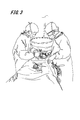
- FIG. 3 is a simulation diagram of a state in which the ring-shaped photographing lighting device 102, which is a basic type, is used in the operating room.
- the surgeon 107 observes the surgical field by looking into the ring formed by the housing 102a of the imaging luminaire 102, and performs the operation using the working space of about 40 cm between the device and the surgical field.
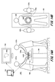
- FIGS. 4A is a top view of the photographic luminaire 102
- FIG. 4B is a bottom view of the photographic luminaire 102
- FIG. 4C is a front view of the photographic luminaire 102
- FIG. 4D is a rear view of the photographic luminaire 102
- FIGS. 4E and 4F It is a side view of the photographic lighting equipment 102.
- the fixation device 102b is provided with a handle 401 for the surgeon 107 to position the imaging lighting device 102 in an appropriate position. ..
- FIG. 5 is a simulation of the surgical field seen from the viewpoint of the surgeon 107. Although the device can be partially seen on the edge of the field of view, there are few parts that block the surgical field, and the surgical operation can be performed comfortably.
- FIG. 6A is a simulation diagram in an operating room using the photographing luminaire 601 according to the modified form example of the first shape
- FIG. 6B is a top view of the photographing luminaire 601 according to the modified form example of the first shape.
- the photographic lighting fixture 601 has a quadrangular housing 601a and a fixing fixture 601b.
- the fixing device 601b is provided with a handle 401 as in the case of the above-mentioned photographing lighting device 102.
- FIG. 6C is a simulation diagram in an operating room using the photographing luminaire 602 according to the modified form example of the second shape
- FIG. 6D is a top view of the photographing luminaire 602 according to the modified form example of the second shape.
- the photographic lighting fixture 602 has an arc-shaped first housing 602a, a first fixing fixture 602b, an arc-shaped second housing 602c, and a second fixing fixture 602d.
- the first fixing device 602b and the second fixing device 602d are each provided with a handle 401, similarly to the above-mentioned photographing lighting device 102.
- FIG. 7A is a simulation diagram in an operating room using the photographing luminaire 701 according to the modified form example of the third shape
- FIG. 7B is a top view of the photographing luminaire 701 according to the modified form example of the third shape.
- the photographic lighting fixture 701 has a linear first housing 701a, a first fixing fixture 701b, a linear second housing 701c, and a second fixing fixture 701d.
- the first fixing device 701b and the second fixing device 701d are each provided with a handle 401, similarly to the above-mentioned photographing lighting device 102.
- FIG. 7C is a simulation diagram in an operating room using the photographing luminaire 702 according to the modified form example of the fourth shape
- FIG. 7D is a top view of the photographing luminaire 702 according to the modified form example of the fourth shape.
- the photographic lighting fixture 702 has a V-shaped housing 702a and a fixing fixture 702b.
- the fixing device 702b is provided with a handle 401 as in the case of the above-mentioned photographing lighting device 102.
- FIG. 8A is a simulation diagram in an operating room using the photographing luminaire 801 according to the modified form example of the fifth shape
- FIG. 8B is a top view of the photographing luminaire 801 according to the modified form example of the fifth shape
- 8C is a side view of the photographing luminaire 801 according to the fifth modified form example.
- the photographic lighting fixture 801 has a housing 801a having an arc shape in the vertical direction and a fixing fixture 801b.
- the fixing device 801b is provided with a handle 401 as in the case of the above-mentioned photographing lighting device 102.
- FIG. 8D is a simulation diagram in an operating room using the photographing luminaire 802 according to the modified form example of the sixth shape
- FIG. 8E is a top view of the photographing luminaire 802 according to the modified form example of the sixth shape
- FIG. 8F is a side view of the photographing luminaire 802 according to the example of the modified form of the sixth shape.
- the photographic lighting fixture 802 has a housing 802a having a portion of an arc in the vertical direction and further having ends of the arc at both ends of the arc, and a fixing fixture 802b.
- the fixing device 801b is provided with a handle 401 as in the case of the above-mentioned photographing lighting device 102.
- a sufficiently large number of camera + light combinations can be arranged in the same manner as the ring type which is the basic type, so that it is possible to create a multi-viewpoint image.
- the C-type x 2 in FIGS. 6C and 6D, and the I-type x 2 in FIGS. 7A and 7B are devices in front of the operator and assistant in order to further reduce visual field obstruction due to the 360 ° ring type. It is devised so that it can be eliminated and a better field of view and workability can be secured. On the other hand, it is undeniable that the quality of multi-view video may deteriorate because the number of cameras and lights that can be placed is reduced in this format at the cost of improving the field of view.
- FIGS. 8A, 8B and 8C show an example of a modified form in which a plurality of cameras and lights are arranged in an arch shape in a narrow range between the operator and the assistant in the vertical direction. It is possible to arrange many cameras + lights in the vertical direction while maintaining the visibility and workability of the surgeon and assistant.
- FIGS. 8D, 8E and 8F show a combination of the C type ⁇ 2 shown in FIG. 6D and the arch type shown in FIGS. 8B and 8C. It is possible to maintain good visual field and workability of the surgeon and assistant, and to arrange a sufficient number of cameras + lights to compose a multi-view visual field image.
- FIG. 9A is a top view of the photographing instrument 901 as a variation without illumination
- FIG. 9B is a schematic view showing a usage state of the photographing instrument 901.
- the photographing apparatus 901 only the plurality of cameras 201 are incorporated in the housing 901a by removing the illumination 202 from the photographing lighting apparatus 102.
- the photographing luminaire 102 is based on a structure in which both a plurality of cameras and a plurality of lights are arranged alternately, for example, but as shown in FIGS. 9A and 9B, there is a variation without illumination. , It is also assumed that it will be designed and used as a photographing device 901 with a plurality of cameras. In this case, since the shadowless lighting installed in the existing operating room can be diverted, it is advantageous in terms of the cost required when introducing the equipment.
- FIG. 10A is a top view of the luminaire 1001 as a variation without a camera
- FIG. 10B is a schematic view showing a usage state of the luminaire 1001.
- the lighting fixture 1001 only the plurality of lightings 202 are incorporated in the housing 1001a, excluding the camera 201 from the photographing lighting fixture 102.
- the photographing lighting fixture 102 is based on a structure in which both a plurality of cameras and a plurality of lights are arranged alternately, for example, but as shown in FIGS. 10A and 10B, there are variations of only lighting. is assumed.
- the conventional shadowless lamp installed above the surgeon 107 blocks the light from the surgeon 107's head and body, and the lighting position needs to be adjusted frequently, but it is installed between the surgeon's crown and the patient.
- This device is a completely shadowless lighting device that is not obstructed by the surgeon's head or body.
- the photographing luminaire 102 of the present invention is a straight line having a finite length as shown in FIGS. 3, 4, 5, 6, 7, and 8 in order to minimize the obstruction of the operator's line of sight. Or, it is formed in various shapes of a finite length curve.
- the thickness of the housing 102a is formed as thin as possible according to the sizes of the plurality of cameras 201 and the lighting 202 to be housed so as not to interfere with the operator.
- the photographing luminaire 102 is formed of a housing made of wire member of finite length, including the linear photographing luminaire 102.
- the shape of the photographing luminaire 102 of the present invention is not limited to those illustrated in FIGS. 3, 4, 5, 6, 7, and 8, but may interfere with the operator's field of view or work. Includes all housing shapes to fulfill the purpose of not being.
- the plurality of cameras and the plurality of lights housed in the housing having a finite length curve shape are all arranged toward the surgical field 106a, which is the subject.
- the photographing illuminating device 102 used in the multi-viewpoint video photographing apparatus 101 of the present invention can take various shapes.
- the housing 102a is preferably made of a lightweight and highly rigid material such as an aluminum alloy, polycarbonate, or carbon.
- the camera 201 and the lighting 202 may be attached to a flexible pipe made of stainless steel or the like used for a water pipe or the like so as to be freely deformable according to the form of the surgical field 106a. Any material such as a flexible pipe that can be freely deformed can also be deformed into the various housing shapes described above.
- FIG. 11 is a block diagram showing a hardware configuration of the multi-viewpoint video capturing apparatus 101 according to the embodiment of the present invention.
- the multi-viewpoint video imaging device 101 includes a camera array unit 1101, an illumination array unit 1102, and a video illumination processing device 103 connected to these.
- the camera array unit 1101 and the illumination array unit 1102 are built in the photographing lighting equipment 102.
- a large screen external monitor 104 is connected to the video illumination processing device 103 through the network 1103.
- the camera array unit 1101 is an aggregate of a plurality of cameras 201 incorporated in the photographing lighting fixture 102 described with reference to FIGS. 1 and 2. These cameras 201 are connected to a serial interface 1128 such as a USB interface included in the video illumination processing device 103.
- the lighting array unit 1102 is an aggregate of a plurality of lighting 202s incorporated in the photographing lighting fixture 102 described with reference to FIGS. 1 and 2.
- the illumination 202 designated by the video illumination processing device 103 is selectively emitted and controlled through the multiplexer 1105 controlled by the microcomputer 1104. Then, it is driven by the current flowing from the power supply voltage node through the current limiting resistor R1106 and the multiplexer 1105.
- the switching control of the multiplexer 1105 is configured so that not only one illumination can be selected, but also a plurality of illuminations can be selected at the same time, including simultaneous lighting of all the illuminations, if necessary. ..
- a microcomputer 1104 is connected between the multiplexer 1105 and the image lighting processing device 103, and the microcomputer 1104 controls the multiplexer 1105 according to the instruction of the image lighting processing device 103.
- the microcomputer 1104 is connected to a serial interface 1128 such as a USB interface included in the video lighting processing device 103.
- the microcomputer 1104 includes a CPU 1108, a ROM 1109, and a RAM 1110 connected to the bus 1107, and a serial interface 1111 (abbreviated as "SI / F" in FIG. 11) such as a USB interface.
- the multiplexer 1105 is connected to the bus 1107 and is controlled by the microcomputer 1104.
- the image lighting processing device 103 which is a well-known computer, includes a CPU 1122, a ROM 1123, a RAM 1124, a display unit 1125, an operation unit 1126, and a non-volatile storage 1127 connected to the bus 1121.
- the CPU 1122 reads out from the non-volatile storage 1127 or the ROM 1123 and executes a software program that realizes the functions of each part included in the video lighting processing device 103.
- the RAM 1124 the images of all the cameras 201 received from the camera array unit 1101 and the variables generated during the arithmetic processing performed in the image illumination processing device 103 are temporarily written.
- the CPU 1122 executes the program recorded in the non-volatile storage 1127 or the ROM 1123, various functions of the video illumination processing device 103 are realized.
- the bus 1121 is connected to a serial interface 1128 such as USB and a NIC (Network Interface Card) 1129 as a communication interface.
- a serial interface 1128 such as USB
- a NIC Network Interface Card
- An external monitor 104 is connected to the NIC 1129 through the network 1103.
- the external monitor 104 includes a well-known computer, which operates a network OS and functions as an external monitor 104 of the image lighting processing device 103.
- the display unit 1125 of the video illumination processing device 103 may be used as it is as a monitor, but generally, the connection cable between the display unit 1125 and the video illumination processing device 103 has a length limitation, so that the external monitor 104 and the network It is preferable to connect at 1103. Then, when the video illumination processing device 103 is constructed as a network moving image server, a plurality of external monitors 104 can be easily connected, so that the same desired video can be displayed on different monitors at the same time. Therefore, even if the external monitor 104 breaks down due to some accident, it is possible to prevent a surgical accident by operating the spare external monitor 104 as it is.
- FIG. 12 is a block diagram showing a software function of the video lighting processing device 103.
- the image lighting processing device 103 includes an input / output control unit 1201, a camera calibration processing unit 1202, a presentation viewpoint gazing point determination processing unit 1204, an image processing unit 1205, a lighting determination processing unit 1206, and a display unit 1125.
- the camera array unit 1101 is composed of a large number of cameras 1 to N embedded in the imaging lighting device 102 and arranged so as to surround the periphery of the surgical field 106a, and photographs the surgical field 106a from various directions during surgery. do.
- the lighting array unit 1102 is embedded in the photographing lighting device 102 together with the camera 201 and arranged so as to surround the periphery of the surgical field 106a, and usually equal to the number of cameras 201 in the camera array unit 1101. Consists of N. Then, the illumination 202 adjacent to the camera 201 selected by the presentation viewpoint gazing point determination processing unit 1204 is controlled to emit light. Also, if necessary, all lighting is controlled to emit light all at once.
- the input / output control unit 1201 receives the video data obtained from the camera array unit 1101 and also gives the illumination array unit 1102 control information for switching the illuminations 1 to N.
- the input / output control unit 1201 and the camera array unit 1101 are connected by a bidirectional serial interface 1128. All cameras 201 of the camera array unit 1101 transmit video data to the input / output control unit 1201.
- the input / output control unit 1201 and the lighting array unit 1102 are connected by a USB interface.
- the input / output control unit 1201 receives a lighting command from the lighting determination processing unit 1206 described later, the input / output control unit 1201 transmits a light emission command to the lighting 202 designated by the lighting determination processing unit 1206 in accordance with the lighting command.
- the microcomputer 1104 that receives the light emission command from the input / output control unit 1201 in the illumination array unit 1102 controls the multiplexer 1105 to control the light emission of the designated illumination 202.
- the input / output control unit 1201 and the camera calibration processing unit 1202 are connected by a serial interface.
- the camera calibration processing unit 1202 estimates camera parameters such as the positions, postures, and focal lengths of the cameras 1 to N constituting the camera array unit 1101 based on the image information.
- the camera 201 embedded in the photographing lighting fixture 102 is composed of an angle of view in which a common area is observed in images of adjacent cameras 201. Then, the camera parameters such as the position, posture, and focal length of each camera 201 with respect to the surgical field 106a, which is the subject, are estimated from the correspondence of the common observation areas.
- Partial image data of surgical instruments such as scalpels, tweezers, and scissors and observation position coordinate information cut out from the multi-viewpoint video data are stored in the RAM 1124 or the non-volatile storage 1127 as the gazing point article image and the gazing point coordinates 1207. ..
- the cut-out partial image data of the operator's hand and the observation position coordinate information are stored in the RAM 1124 or the non-volatile storage 1127 as the gazing point article image and the gazing point coordinate 1207.
- the reason for preparing multiple multi-viewpoint video data of the operator's fingers is that the fingers freely change their shapes, so in order to increase the probability of image matching, multiple multi-viewpoint video data are used as the gaze-point article video and This is because it is necessary to prepare it as the gazing point coordinate 1207.
- the gazing point is a triangulation based on camera parameters for a representative point (two-dimensional point) of a partial region of the subject that the operator is paying attention to in the multi-viewpoint image data obtained from the camera array unit 1101. Refers to a three-dimensional point estimated by applying.
- the input / output control unit 1201 and the presentation viewpoint gaze point determination processing unit 1204 are connected by a serial interface.
- the presentation viewpoint gazing point determination processing unit 1204 refers to the gazing point article image and the gazing point coordinate 1207, and selects the part of the subject that the surgeon 107 wants to see from all the images of the cameras 201 received from the input / output control unit 1201. Detect and estimate its two-dimensional position coordinates.
- the presentation viewpoint gaze point determination processing unit 1204 further determines the presentation viewpoint, which is the viewpoint at which the gaze point can be photographed most appropriately.
- the presentation viewpoint gaze determination processing unit 1204 performs this presentation viewpoint determination process by taking into consideration the reflection of the surgeon 107's hand and surgical instrument on the captured image, and then taking a picture from a direction suitable for the surgeon 107's observation. Is selected from the cameras 1 to N constituting the camera array unit 1101.
- the camera calibration processing unit 1202 and the presentation viewpoint gaze point determination processing unit 1204 are connected by a serial interface.
- the presentation viewpoint gazing point determination processing unit 1204 is a subject that the assistant 107b of the surgeon 107a wants to see from the two-dimensional position coordinates estimated as camera parameters such as the position, orientation, and focal length of the camera 201 received from the camera calibration processing unit 1202. That is, the three-dimensional coordinates of the gazing point are calculated based on the stereo vision.
- the presented viewing point gazing point determination processing unit 1204 identifies the camera 201 that clearly captures the gazing point. The above is the determination process of the presentation viewpoint by the presentation viewpoint gaze determination processing unit 1204.
- the illumination determination processing unit 1206 basically generates information for on-controlling the illumination 202 arranged on both sides of the camera 201, which is specified by the presentation viewpoint gaze determination processing unit 1204 to clearly capture the gaze point. do. If a specific camera 201 is not specified, all the lights are turned on.
- the image processing unit 1205 is an interface for outputting the camera 201 that clearly captures the gazing point specified by the presentation viewpoint gazing point determination processing unit 1204 to the display unit 1125, the external monitor 104, or the like.
- the image processing unit 1205 supplies the multi-viewpoint image to the display unit 1125 provided in the operating room, and also provides the multi-viewpoint image to the external monitor 104a via the network 1103.
- the external monitor 104a can display the images of the plurality of cameras 201 at the same time. Among them, for example, one camera image that is closest to the line of sight of the surgeon 107a and captures a clear image that is not obstructed by the surgeon, assistant's hand, or surgical instrument is enlarged and displayed as the main image, and all the participating members Can be shared.
- the external monitor 104b presents the surgeon 107a with an image from an angle different from its own line of sight, or, for example, the external monitor 104c presents image information other than white light captured by near infrared rays.
- It is a display device that can present image information other than direct-view video to the operator.
- the presentation viewpoint gazing point determination processing unit 1204 and / or the image processing unit 1205 is used so that the viewer or the surgeon 107 can view the multi-viewpoint image intuitively or with a simple operation.
- the function of manually selecting the camera 201 from the operation unit may be added.
- FIG. 13 is a flowchart showing a processing flow of the presentation viewpoint gazing point determination processing unit 1204.
- the presentation viewpoint gazing point determination processing unit 1204 sets the position of the camera 201 and the person area volume ( The three-dimensional coordinate information of the position of the hand of the surgeon 107), the position of the gazing point, and the position of the instrument area is acquired (S1302).
- the presentation viewpoint gazing point determination processing unit 1204 determines whether or not the surgeon 107 has a hand between the camera position and the gazing point position based on the three-dimensional coordinate information of the gazing point (S1303). If it is determined in step S1303 that the surgeon 107's hand is between the camera position and the gazing point position (YES in S1303), a camera that does not have the surgeon 107's hand is searched between the camera position and the gazing point position.
- step S1303 When it is determined in step S1303 that there is no hand of the surgeon 107 between the camera position and the gazing point position (NO in S1303), the presentation viewpoint gazing point determination processing unit 1204 subsequently determines the three-dimensional coordinate information of the gazing point. Based on the above, it is determined whether or not there is a surgical instrument between the camera position and the gazing point position (S1304).
- step S1304 determines in step S1304 that there is a surgical instrument between the camera position and the gazing point position (YES in S1304), the surgical instrument exists between the camera position and the gazing point position. Do not search for cameras. If the presentation viewpoint gazing point determination processing unit 1204 determines that there is no surgical instrument between the camera position and the gazing point position in step S1304 (NO in S1304), the used camera address information and zoom in the cameras 1 to N. A value is output (S1306), and a series of processes is completed (S1307).
- the multi-viewpoint imaging apparatus 101 has live magnified information from a viewpoint different from that of the naked eye, in addition to direct vision with the naked eye, in contrast to surgery that has been performed only by direct vision with the naked eye. Is presented to surgeon 107.
- the imaging luminaire 102 equipped with the camera 201 and the luminaire 202 is located between the surgeon 107 and the patient 106, and unlike conventional surgical luminaires, the light of the luminaire is directed by the heads of the surgeons 107a, 107b. It will not be blocked. Therefore, the surgical field 106a and the vicinity of the gazing point are always brightly illuminated by the illumination 202, and the visibility is remarkably improved.
- the surgical field 106a and the gaze point area enlarged and displayed by the multi-viewpoint imaging device 101 are multi-viewpoint images
- the surgical field 106a and the gaze point area can be confirmed three-dimensionally by moving the viewpoint. Can be done.
- the presentation viewpoint gazing point determination processing unit 1204 identifies the gazing point 3D coordinate information in the multi-viewpoint image being photographed from the gazing point 3D coordinate information stored in advance in the gazing point article image and the gazing point coordinate 1207. By doing so, appropriate viewpoint switching can be realized centering on the object of interest (for example, the tip of a scalpel).
- the multi-viewpoint imaging device 101 can significantly improve the certainty and safety of surgery due to the above features.
- the presentation viewpoint can be moved by manual operation through the operation unit 1126.
- the viewpoint is switched around an object other than the object of interest (for example, the tip of a scalpel).
- the observation position of the object of interest for example, the tip of a scalpel
- FIG. 14 is a schematic view showing a usage state of the multi-viewpoint video capturing apparatus 1401 according to the first modification of the present invention.
- the difference between the multi-viewpoint imaging device 1401 shown in FIG. 14 and the multi-viewpoint imaging device 101 shown in FIG. 1 is that the imaging lighting device 1402 is downsized and placed directly on the surgical field 106a of the patient 106. be.
- a hollow ring in which the camera array unit 1101 and the illumination array unit 1102 are arranged is arranged between the patient 106 and the surgeon 107, for example, at a position about 30 cm away from the patient 106. It is attached to the frame.
- the surgeon 107 can perform the operation while visually observing the surgical field 106a.
- the head of the surgeon 107 can be shadowed by the illumination to eliminate the imperfections in the imaging, but the problem is that the frame with the hollow ring obstructs the surgeon 107's field of view. There is.
- a hollow ring in which the camera array unit 1101 and the illumination array unit 1102 are arranged is placed on the peripheral edge of the surgical field 106a of the patient 106. It is installed like this. In this case as well, the surgeon 107 can perform the operation visually. With this surgical procedure, the operation can be performed in the same state as a normal surgical operation, so that the surgeon 107 has less hindrance to the work as compared with the imaging lighting device 102 of FIG. However, since the imaging lighting instrument 1402 comes into contact with the patient 106, the hands of the surgeons 107a and 107b and the surgical instrument may be in the shadow of the illumination.
- FIG. 15 is a schematic view showing a usage state of the multi-viewpoint video capturing apparatus 1501 according to the second modification of the present invention.
- the difference between the multi-viewpoint image capturing device 1501 shown in FIG. 15 and the multi-viewpoint image capturing device 101 shown in FIG. 1 and the multi-viewpoint image capturing device 1401 shown in FIG. It is a point that it is further miniaturized than the imaging luminaire 1402 according to the above, and is directly inserted into the surgical field 106a of the patient 106.
- the imaging lighting device 1502 shown in FIG. 15 is an example in which a hollow ring in which the camera array unit 1101 and the lighting array unit 1102 are arranged is inserted into the abdominal cavity of the patient 106 and installed so as to look down on the surgical site from the upper part of the abdominal cavity. According to this surgical procedure, the surgeons 107a and 107b can perform the operation while viewing the captured image, and the camera 201 can capture the entire abdominal cavity. However, the hollow ring in which the camera 201 and the illumination array unit 1102 are arranged must be taken in and out from the insertion port provided in the abdomen of the patient 106.
- Imaging lighting device 1601 for simultaneously photographing the blood vessels of the surgical field 106a of the patient 106 using an infrared LED 1605 and a cold mirror 1606 or a hot mirror When an image of a blood vessel is displayed on an external monitor 104 together with a visible light image during a surgical operation, it is possible to prevent the occurrence of a medical accident that damages the blood vessel, and further improvement in safety can be expected.
- FIG. 16 is a schematic view showing a photographing luminaire 1601 according to a third modification of the present invention, an LED lighting 1602 incorporated in the photographing illuminating device 1601, and a camera unit 1603.
- the LED illumination 1602 has a visible light LED 1604 and an infrared LED 1605.
- the visible light LED 1604 and the infrared LED 1605 are continuously emitting light at the same time.
- the camera unit 1603 includes a cold mirror 1606 installed at an angle of 45 ° on the optical axis, a first camera 1007 installed at a position passing through the cold mirror 1606 on the optical axis, and a cold mirror 1606 on the optical axis. It has a second camera 1008 installed at orthogonal positions.
- the cold mirror 1606 transmits near-infrared light and reflects visible light. Therefore, the first camera 1007 captures an infrared image, and the second camera 1008 captures a visible light image. Even if a hot mirror that transmits visible light and reflects near-infrared light is installed instead of the cold mirror 1606, the first camera 1007 captures a visible light image and the second camera 1008 captures an infrared image. be able to. In either case, since the visible light image and the infrared image can be simultaneously captured from the incoming light, the visible light image and the infrared image can be simultaneously displayed on the display unit 1125 and the external monitor 104.
- FIG. 17A is a schematic view showing the LED lighting 1602 and the camera 201 of the photographing lighting fixture according to the fourth modification of the present invention
- FIG. 17B is a time chart showing the light emission timings of the visible light LED 1604 and the infrared LED 1605.
- FIG. 17C is a block diagram showing a software function of the infrared image acquisition unit 1702 provided in the input / output control unit 1201 of the image illumination processing device 103.
- the camera 201 is a general image sensor, and does not have a special structure as in the third modification. Instead, the camera 201 outputs a frame timing pulse.
- the frame timing pulse is input to the light emission timing control unit 1701.
- the light emission timing control unit 1701 synchronizes the light emission timings of the visible light LED 1604 and the infrared LED 1605 with the frame timing pulse included in the video data output by the camera 201, and emits light from the visible light LED 1604 and the infrared LED 1605 at the timing shown in FIG. 17B. To control. That is, the light emission timing control unit 1701 emits only the visible light LED 1604 at the time of the first frame timing t1711, emits only the infrared LED 1605 at the time of the second frame timing t1712, and emits light only with the visible light LED 1604 at the time of the third frame timing t1713. Turn off both infrared LEDs 1605. This operation is repeated.
- the infrared LED lighting shooting video data obtained at the second frame timing and the infrared LED turning off shooting video data obtained at the third frame timing are formed in the input / output control unit 1201 of the video lighting processing device 103. It is input to the infrared image acquisition unit 1702 (see FIG. 17C). Further, as shown in FIG. 17C, the infrared image acquisition unit 1702 has an infrared LED on photography image buffer 1703 that holds the infrared LED on photography image data and an infrared LED off photography image buffer 1704 that holds the infrared LED off photography image data. And an adder 1705.
- the infrared LED on shooting video data output from the infrared LED on shooting video buffer 1703 and the infrared LED off shooting video data output from the infrared LED off shooting video buffer 1704 are input to the adder 1705.
- the adder 1705 subtracts the infrared LED off shooting video data from the infrared LED on shooting video data for each pixel. Then, the infrared LED off shooting image data, that is, the noise component due to visible light, which is included in the infrared LED on shooting image data, is subtracted.
- the frame rate is reduced to 1/3 as compared with the third modification, the infrared image can be acquired by using the general-purpose camera 201 as it is. Therefore, as in the case of the third modification, it is possible to prevent the occurrence of a medical accident that damages a blood vessel in a surgical operation, and improvement in safety can be expected.
- the video data of the specific wavelength spectrum can be acquired. Becomes possible.
- the video lighting processing device 103 a general personal computer can be used as it is. Therefore, not only the multi-viewpoint image of the surgical field 106a by visible light and the multi-viewpoint image of blood vessels by infrared light are displayed on the display unit 1125 and the external monitor 104, but also the information output by the external device is displayed at the same time. It also becomes possible.
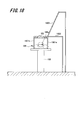
- FIG. 18 is a schematic view showing a variation of the fixing device 102b according to the fifth modification of the present invention.
- the fixing device 102b shown in FIG. 1 is provided to maintain the imaging lighting device 102 floating from the surgical field 106a.
- the fixture 102b has a structure suspended from the ceiling of an operating room (not shown) so as not to interfere with the operation of the surgeon 107.
- the legs 1801a and 1801b extending directly below the photographing luminaire 102 and the extension arm 1802 extending directly beside the photographing luminaire 102 It is also conceivable to provide. Further, an extension arm 1803 extending diagonally upward of the photographing luminaire 102 can be provided. As described above, various variations can be considered as the form of the fixing instrument for maintaining the state in which the imaging lighting instrument 102 is floated from the surgical field 106a.
- the multi-viewpoint imaging device 101 aims to provide the surgeon 107 in an integrated manner with a wide variety of information essential for surgery, such as a cockpit of an airplane.
- preoperative simulation information such as preoperative CT images, MRI images and 3D reconstructed images, and appropriate infrared images of the main part are appropriate.
- Navigation information such as vascular travel can be displayed on the external monitor 104 in an appropriate layout according to the progress of surgery.
- patient 106 vital information acquired in real time such as blood pressure, pulse, electrocardiogram, and electroencephalogram of patient 106
- medical safety information such as surgical procedure / surgical members
- medical cost information such as equipment used should be displayed as shared information. It may be.
- the multi-viewpoint imaging device 101 is expected to play a major role in enhancing the safety of surgery.
- Various information such as live magnified information, infrared information, preoperative radiographic image information, 3D simulation information, and medical safety information are displayed to the surgeon 107 for surgery that has been performed only by direct vision with the naked eye. This makes it possible to significantly improve the safety of surgery.
- the surgical light is an indispensable equipment in all operating rooms, but the illuminated camera device used in the embodiment of the present invention can play a role as a more compact surgical light.
- the illuminated camera device used in the present invention a large-scale surgical light equipment is no longer required in the operating room, and it is said that there are about 20,000 operating rooms throughout Japan. There is also the possibility of becoming.
- the multi-viewpoint imaging device 101 can be said to be a completely new surgical support system, and can be said to have the potential to completely change the scenery of operating rooms in the world.
- this multi-viewpoint imaging device is supposed to be used mainly in surgical operations targeting living organisms, but it is a clear lighting environment that is not obscured by the operator's head or body.
- the feature of this device which enables unobstructed surgical field imaging, is that it is more veterinary for animals in fields such as pathological anatomy, judicial anatomy, surgical anatomy, and educational anatomy for corpses. It is also effectively applied in the surgical scene.
- the above-described embodiment describes in detail and concretely the configurations of the apparatus and the system in order to explain the present invention in an easy-to-understand manner, and is not necessarily limited to those including all the described configurations. Further, it is possible to replace a part of the configuration of one embodiment with the configuration of another embodiment, and further, it is possible to add the configuration of another embodiment to the configuration of one embodiment. It is also possible to add / delete / replace a part of the configuration of each embodiment with another configuration.
- Multi-viewpoint imaging device 102 ... Imaging lighting equipment, 102a ... Housing, 102b ... Fixed instrument, 103 ... Image lighting processing device, 104 ... External monitor, 105 ... Operating table, 106 ... Patient, 106a ... Surgical field , 107 ... Surgeon, 201 ... Camera, 202 ... Lighting, 203 ... USB Hub, 401 ... Handle, 601 ... Shooting Lighting Equipment, 601a ... Housing, 601b ... Fixing Equipment, 602 ... Shooting Lighting Equipment, 602a ... First Housing , 602b ... First fixing device, 602c ... Second housing, 602d ... Second fixing device, 701 ... Shooting lighting device, 701a ...
- Multi-viewpoint video shooting device 1502 ... Shooting lighting equipment, 1601 ... Shooting lighting equipment, 1602 ... LED lighting, 1603 ... Camera unit, 1604 ... Visible light LED, 1605 ... Infrared LED, 1606 ... Cold mirror, 1701 ... Light emission timing control unit, 1702 ... Infrared image acquisition unit, 1703 ... Infrared LED lighting Shooting video buffer, 1704 ... Infrared LED off Shooting video buffer, 1705 ... Adder, 1801a ... Leg, 1802, 1803 ... Extension arm
Abstract
複数のカメラと複数の照明を、中空型リング状または弧状など、術者の視野や作業の妨げにならない様に工夫した有限長曲線形状の筐体に取り付けた手術用の撮影照明器具を、術者の頭頂と患部の間の空間に配置することにより、術者の頭、体による照明の遮蔽、映像への頭の映り込みを回避した外科手術用の多視点映像撮影装置になる。さらに、複数カメラのコンテキストを推定する機能を具備し、術者の手または手術器具の画像への映り込みの少ないカメラ映像を選定する映像情報処理機能を付加することにより、多視点映像による直視下外科手術の手術支援/記録を可能にする多視点映像撮影装置になる。
Description
本発明は、外科手術や解剖等に用いられる多視点映像撮影装置に関する。
外科手術の基本は開腹、開胸下の広い術部で行われる直視下型手術であり、高難度手術においても様々な不測の事態に対応することができる確実な術式である。しかし、外科医は自分の目で見た情報だけを基にこの直視下型手術を行っているのが現状で、この方法は100年以上も続く近代外科の歴史の中でも、ほとんど改善されていない。
直視下型手術を飛行機の操縦に例えると、現代の外科医は、未だに長時間のフライトを何のサポートもなく、有視界飛行で操縦しているパイロットのような状況にあり、その意味で外科手術の分野はIT技術から取り残された分野であるとも言える。
これに対し、近年、内視鏡を患者の腹部あるいは胸部に挿入し、内視鏡の映像を大画面のモニタで表示して手術を行う、鏡視下手術が急速に普及している。この鏡視下手術では、一つの鮮明な拡大映像情報を参加メンバー全員で共有することができ、安全性の向上に寄与している。さらに、術部の中心を捉えた映像を簡単に記録してアーカイブ化することができるので、若手外科医や学生と振り返り学習をする、外科教育用の外科教材を作成する上でも貢献している面が大きい。
近年、腹腔鏡手術の適応は格段に広がり、多くの高難度の手術を行うまでになっているが、部分的に拡大された術部画像を見ながら、不自由な器具を使って行う術式には、かえってトラブルを起こすリスクもある。このため、直視下手術は、依然として外科手術において中心的な役割を果たし続けている。
そこで、外科手術の基本である直視下手術において、IT情報を有効に提供する技術開発が強く求められている。
そこで、外科手術の基本である直視下手術において、IT情報を有効に提供する技術開発が強く求められている。
従来、直視下手術における映像撮影は術者の頭上に配置した1つのビデオカメラで撮影することが広く行われてきた。しかし、術者の覗き込み動作により頭、肩などの体に遮られることが多く、有効な映像を撮影できない場面が多くあった。これを解決するためには、少なくとも1人の映像担当スタッフを配置し、複数の術者の頭などの隙間を狙ってカメラ位置を頻回に調整して撮影する必要があった。
しかし、そういった労力を割いたとしてしてもなお、術者の覗き込みによる映像の妨げを完全に回避することはできなかった。また、人的資源に比較的余裕のある大病院などでは、撮影を企図した特別な直視下手術においてはこのような人員を配置することも可能であるが、それでも、日常行われる全ての手術で気軽に撮影することはできなかった。まして、人員の少ない市中病院などで、直視下手術の有効な手術映像記録を行うことは殆どの場合、できないのが現状である。
直視下手術において、術者の視線から見た術野を介助者や術野外の観察者(麻酔科医、看護師、医学生など)も見ることができれば、腹腔鏡下手術のような術野の共有という恩恵に浴することができるが、今までそれを叶える映像機器システムはなかった。
一つの対応策として、術者の頭やメガネに小型カメラを取り付け術者の視線を撮影する試みは多くなされている。しかし、実臨床上は、術者の不規則な頭の動きによって画面が非常に大きくブレる為、とても観察に耐えられるような画像が撮れないのが実情であった。
一つの対応策として、術者の頭やメガネに小型カメラを取り付け術者の視線を撮影する試みは多くなされている。しかし、実臨床上は、術者の不規則な頭の動きによって画面が非常に大きくブレる為、とても観察に耐えられるような画像が撮れないのが実情であった。
さらに、術者は集中して非常に狭い術野だけを見ていることが多くなるが、術者にとっては、広い視野から俯瞰的に術野を見た像や、術者の逆方向の視点から術野を見た像を参考にしながら手術を行うことは、手術の安全性を高める上でも有効である。
しかし、今まで術者は自分の視線以外の視点から見た術野映像を見ることはできなかった。また、白色光以外に、遠赤外線を使って、ICG蛍光色素を注入したがん病巣やリンパ節を浮き上がらせたり、血管走行を描出したりする技術を応用して、術者に白色光以外の映像情報を提供することも、近未来の手術支援装置としては大切な機能である。
しかし、今まで術者は自分の視線以外の視点から見た術野映像を見ることはできなかった。また、白色光以外に、遠赤外線を使って、ICG蛍光色素を注入したがん病巣やリンパ節を浮き上がらせたり、血管走行を描出したりする技術を応用して、術者に白色光以外の映像情報を提供することも、近未来の手術支援装置としては大切な機能である。
特許文献1には、外科手術などの医療の撮影に際し、治療者の覗き込み動作による頭、術者の手や手術機械等によるカメラの視野障害を避けて、医療措置や治療対象患部状態などを高確率で画面に表示するカメラシステムが記載されている。
特許文献1に記載の技術は、術者の頭上に複数の光源を備えた無影灯付きカメラ機構を配置している。この無影灯付きカメラ機構は、一つの中央カメラと複数の周囲カメラを有し、照明の対象である術部を複数の視点から同時に撮影するように構成されている
特許文献1に記載の技術は、術者の頭上に複数の光源を備えた無影灯付きカメラ機構を配置している。この無影灯付きカメラ機構は、一つの中央カメラと複数の周囲カメラを有し、照明の対象である術部を複数の視点から同時に撮影するように構成されている
さらに、特許文献1に記載の技術では、モニタ機構が設けられ、このモニタ機構により、中央カメラ及び複数の周囲カメラで撮影された複数の映像の中から必要な映像が選択されて、ディスプレイ装置に表示されるようになっている。
また、特許文献2には、赤外線光とコールドミラーまたはホットミラーを用いて、血管の映像を撮影する技術が開示されている。
また、特許文献2には、赤外線光とコールドミラーまたはホットミラーを用いて、血管の映像を撮影する技術が開示されている。
近年、あるシーンを複数のカメラで同期して撮影し、任意の視点(仮想視点)からの見える風景を再現した画像(自由視点画像)を生成する技術が発展し、例えば、サッカーやバスケットボールのハイライトシーン等を様々な角度から見ることができるようになっている。
直視下外科手術に多視点映像技術を応用するためには、スポーツ観戦などを想定した多視点自由映像技術とは全く異なる課題が存在する。それは、被写体とカメラと観察者の位置関係がスタジアムでの撮影環境と手術室での撮影環境では大きく異なるという点である。
スタジアムでは、被写体、すなわち選手とカメラを結ぶ直線上に観察者、すなわち視聴者が存在することはなく、遮蔽物はない。
スタジアムでは、被写体、すなわち選手とカメラを結ぶ直線上に観察者、すなわち視聴者が存在することはなく、遮蔽物はない。
一方、直視下外科手術では、頭上に設置したカメラと被写体である術部の間に観察者である外科医が必ず存在してしまう。この外科医の頭、肩などが第一の遮蔽物になり、さらに、術野の直上で作業する外科医の手、手術器具が第二の遮蔽物になり、複数のカメラから同期した被写体の画像を得ることができない。
特許文献1は直視下外科手術における上記の遮蔽課題を十分に考慮せずに外科手術に多視点映像を応用しようとした例である。ここに記載される無影灯付きカメラ機構は非常に大きく、外科医の頭上に配置されているため、設置した複数のカメラの多くは外科医の頭に遮られ、有効に術部を撮影することが難しい。結局、従来の1つのカメラで直視下手術を撮影する場合と同様に、カメラ撮影専用のスタッフを配置し、カメラ位置を調整し続けなければ意味のある画像を得ることは困難である。
さらに、複数のカメラの多くは外科医の頭、肩などに遮られてしまい無効になるので、多視点映像を得るための十分に多くの複数のカメラからの有効な映像を得ることは困難であった。
さらに、複数のカメラの多くは外科医の頭、肩などに遮られてしまい無効になるので、多視点映像を得るための十分に多くの複数のカメラからの有効な映像を得ることは困難であった。
一方、手術を遂行する上で不可欠な要素は術野を照らす照明装置である。複数のライトが設置された無影灯は、文字通り影ができないことを期待して設計されている。しかし、実際には特許文献1に記載されるような大きな無影灯による照明は、外科医の頭、肩などに遮られて有効な光量が術野に届かないことが多くなる。その結果、手術中に外科医自身、もしくは外から助手により、頻回に照明装置の位置を調整する必要に迫られる。
このように、頭上の無影灯付き複数カメラ機構も含めて、従来の機器では、術野のビデオ画像の表示及び記録を、カメラ撮影専用のスタッフなしに有効に行うことは難しかった。また、近年スポーツ観戦などで飛躍的に進歩している多視点映像というIT技術を、外科手術領域に応用することはできなかった。
自由視点映像を生成する方式として、例えば特許文献3に記載されるような、被写体の位置や形状のような幾何学的情報の推定法に関する技術がある。しかしながら、外科手術にとって有意義な自由視点映像を生成するためには、幾何学的な情報だけでは不十分であり、それに加えて、意味的なコンテキスト情報の取得、及びそれに基づいた提示映像生成が必要になる。
したがって、上記した術者の頭、体により映像または照明が遮蔽されるという第1の課題を解決したとしても、被写体の直上には必ず術者の手、手術器具という第2の遮蔽物が存在するため有効な多視点映像を得ることはできない。つまり、手術現場に多視点映像技術を応用するためには、撮影シーンの状況判断、つまり、コンテキスト情報を推定し、コンテキスト情報に基づいて、術者の手、手術器具が障害となっていないカメラ映像を映像情報的に自動選択する機能を備える必要がある。
さらに、本装置をリアルタイムで手術ナビゲーションとして応用する場面において、術者の視点からは気づくことができない他の視点からの映像を術者に提示することができれば、手術の安全性を高める有効な技術になる。
そのためには、広い撮影範囲の中で術者が注視する、限られた狭い領域を自動認識できる機能を備える必要がある。その上で、術者が現在注視している以外に術者に提示すべき有効な画像を判断して提示する機能を備える必要がある。
そのためには、広い撮影範囲の中で術者が注視する、限られた狭い領域を自動認識できる機能を備える必要がある。その上で、術者が現在注視している以外に術者に提示すべき有効な画像を判断して提示する機能を備える必要がある。
本発明の目的は、撮影専用のカメラスタッフを配置することなく、術者の頭、体に遮られることのない、さらに術者の手、手術器具に妨げられることのない手術術野の画像表示及び記録を過不足なく行うことができる多視点映像撮影装置を提供することにある。
すなわち、本発明は、既存の装置では回避することができなかった術者の頭、体により映像、照明が遮蔽されるという第一の課題を機器形状の工夫及び機器の配置位置の工夫で解決した上で、さらに、術者の手、手術器具による第二の遮蔽問題を映像情報処理技術で解決し、外科手術分野に多視点映像撮影技術を応用することを目的にする。
一方、本発明の多視点映像撮影装置は、術者の視線の妨げ、作業の障害にならないように形状、大きさ、配置を工夫することが要件となる。
すなわち、本発明は、既存の装置では回避することができなかった術者の頭、体により映像、照明が遮蔽されるという第一の課題を機器形状の工夫及び機器の配置位置の工夫で解決した上で、さらに、術者の手、手術器具による第二の遮蔽問題を映像情報処理技術で解決し、外科手術分野に多視点映像撮影技術を応用することを目的にする。
一方、本発明の多視点映像撮影装置は、術者の視線の妨げ、作業の障害にならないように形状、大きさ、配置を工夫することが要件となる。
上記課題を解決するために、本発明の多視点映像撮影装置は、複数のカメラを術者が作業対象とする被写体に向けて、リング状の円形もしくは弧状などの有限長曲線形状の筐体に取り付けた撮影器具と、撮影器具を、術者の頭頂と被写体との間の位置に配置する固定器具とを備える。
本発明の好ましい形態としては、撮影器具に取り付けた複数のカメラの位置、姿勢、焦点距離を含むカメラパラメータを、複数のカメラが撮影した被写体の撮影情報に基づいて推定するカメラ較正処理部と、外科医が注目する被写体の領域である注視点を多視点画像データ中で検出し、カメラパラメータを参照して注視点の三次元座標情報を推定し、三次元座標情報に基づき、前記注視点を最も良い状態で撮影するカメラを1つ以上選択する提示視点注視点判定処理部とを備える。
さらに、筐体に取り付けられた複数のカメラの間に複数の照明を配置することにより、術者の頭や肩による遮蔽のない照明環境をも具備する。
さらに、筐体に取り付けられた複数のカメラの間に複数の照明を配置することにより、術者の頭や肩による遮蔽のない照明環境をも具備する。
本発明によれば、撮影専用のカメラスタッフを配置することなく術者の頭や体に遮られることのない照明環境のもとで明瞭な術野画像を撮影し続けることが可能である。さらに術者が注視する術野中心を多視点から有効に捉える機能を備えることにより、外科医の視点以外からの詳細な術野情報をリアルタイムに外科医に提供する施術支援機能も具備し、直視下手術の安全性向上に寄与できる。また、この明瞭な術野画像を録画することは、信頼性の高い画像的な手術記録の保存になる。
これは、診療情報記録としての価値が非常に高く、かつ、外科教育にも大きく寄与することが期待できる。さらに、医療スタッフが少ない医師不足地域の病院などで行われる手術において、撮影スタッフなしに明瞭な術野画像を得ることができるので、これを遠隔地にいる熟練外科医にリアルタイムに送信してアドバイスを受ける等、遠隔地医療の安全性を高めるという応用も期待できる。
加えて、後述するように、変形例3においては、腹腔鏡手術においてカメラを持つ医師を不要とし、人的資源の効率化を図るだけでなく、従来の狭い視野ではなく、広い多視点映像を提供することにより安全性の向上にも寄与することができる。
本発明の多視点映像撮影装置に設置した複数の照明光源は、外科医の頭頂より低い位置に設置されるという本装置の特徴により、一切外科医の頭・体に遮られることがなく、影のない無影環境を術野に提供することができる。さらに、赤外光、紫外光など波長の異なる光源を装備することにより、外科医が肉眼で認識することができない多くの情報を提供することが可能になる。
上記した以外の課題、構成及び効果は、以下の実施形態の説明により明らかにされる。
上記した以外の課題、構成及び効果は、以下の実施形態の説明により明らかにされる。
[多視点映像撮影装置]
図1Aは、本発明の実施形態に係る、多視点映像撮影装置101の使用状態を示す概略図、図1Bは、撮影照明器具102の使用状態を上から見た図である。
図1Aに示すように、多視点映像撮影装置101は、撮影照明器具102と、これに接続される映像照明処理装置103を有する。さらに、映像照明処理装置103には大画面の外部モニタ104が接続されている。
図1Aは、本発明の実施形態に係る、多視点映像撮影装置101の使用状態を示す概略図、図1Bは、撮影照明器具102の使用状態を上から見た図である。
図1Aに示すように、多視点映像撮影装置101は、撮影照明器具102と、これに接続される映像照明処理装置103を有する。さらに、映像照明処理装置103には大画面の外部モニタ104が接続されている。
手術台105には麻酔をかけられ、腹部を切開された患者106が横たわっている。この患者106に外科医107aが執刀を行い、外科医107bが外科医107aの執刀補助を行う。すなわち、外科医107aは執刀を行う外科医であり、外科医107bはその補助者である。以下、外科医107aとその補助者107bを総称して、「外科医107」として記載することにする。
手術台105の横幅は概ね50cm程度である。切開された腹部、すなわち手術術野106aは、開口部が概ね短辺20cm程度であり、深さが概ね10cm程度である。
手術台105の横幅は概ね50cm程度である。切開された腹部、すなわち手術術野106aは、開口部が概ね短辺20cm程度であり、深さが概ね10cm程度である。
図1A及び図1Bに示すように、手術術野106aの中心からおよそ40cm程度、上方向に離間した位置に、中空リング形状の撮影照明器具102が設置される。撮影照明器具102は、外科医107a、107bが手術術野106aを視認する上でその視野障害にならないように、図1の例では円または楕円リング形状の筐体に、複数のカメラ(図2B参照)と複数の照明(図2B参照)が、手術術野106aに向けて設置されている。
外科医107は、撮影照明器具102の中空部分から手術術野106aを覗き込むとともに、撮影照明器具102の下の40cm程度の空間に手を差し込み、手術操作を行う。この手術操作を行うスペースを確保するために、撮影照明器具102は例えば固定器具102bにより術野上の構造物(例えば天井)から吊り下げて、外科医の頭頂と手術術野106aの間に設置される。
外科医107は、撮影照明器具102の中空部分から覗き込むように手術術野106aを視認することができるが、外部モニタ104に表示される手術術野106aの映像を参照しながら、撮影照明器具102と手術術野106aの間の空間を使って執刀及び執刀補助を行うこともできる。
従来の直視下手術では、術部の真上60cmは、立ち入ることができない神聖な領域として外科手術医療の界隈で広く認識されており、新たな医療機器を開発して配置することがためらわれる領域であった。すなわち、直視下手術における手術のモニタリングは、執刀する外科医107a、107bの肉眼による手術術野106aの目視が全てであったため、術部の真上60cmに何らかの物体を配置することは外科医107の視界を妨げるものと認識されていた。
本発明の実施形態に係る多視点映像撮影装置101に用いられる撮影照明器具102は、このタブーであった領域である、術部の真上60cm以内に配置される器具である。しかし、外科医107は、中空に設置されたリング状の本装置を覗き込むように術野を視認することができ、一方、本装置と患部との間には十分な作業空間が確保されているので、外科医107は滞りなく手術操作を行うことができる。そして、外科医107の頭や肩に遮られることのない照明環境のもとで明瞭な術野画像を撮影し続けることが可能になる。
撮影照明器具102に設けられている多数のカメラは、手術術野106aを取り囲むように配置される。したがって、手術の際に手術術野106aを様々な方向から撮影することが可能である。
従来、手術術野106aを様々な方向から撮影するためには、必要な方向へその都度カメラを動かしていた。本発明の実施形態に係る、多視点映像撮影装置101の一部を構成する撮影照明器具102の場合、個々のカメラを物理的に動かす機能は必要ない。予め手術術野106aを取り囲むように配置された複数のカメラの映像を、必要に応じて電子的に切り替えることにより、外科医107が必要とする撮影方向の映像を容易に取得可能になる。
従来、手術術野106aを様々な方向から撮影するためには、必要な方向へその都度カメラを動かしていた。本発明の実施形態に係る、多視点映像撮影装置101の一部を構成する撮影照明器具102の場合、個々のカメラを物理的に動かす機能は必要ない。予め手術術野106aを取り囲むように配置された複数のカメラの映像を、必要に応じて電子的に切り替えることにより、外科医107が必要とする撮影方向の映像を容易に取得可能になる。
撮影照明器具102のカメラが撮影する映像は、手術台105の近傍に設置されている外部モニタ104で見ることができる。外科医107は、肉眼で手術術野106aを見るとともに大画面の外部モニタ104でも手術術野106aを確認することができる。
さらに、多視点映像撮影装置101はその名称に示されるように、複数のカメラから得られる映像を基に、自由な視点からの映像を形成することができる。したがって、カメラを切り替えて視点を移動することで、被写体である手術術野106aを立体的に見ることも可能になる。
さらに、多視点映像撮影装置101はその名称に示されるように、複数のカメラから得られる映像を基に、自由な視点からの映像を形成することができる。したがって、カメラを切り替えて視点を移動することで、被写体である手術術野106aを立体的に見ることも可能になる。
[撮影照明器具102の全体像]
図2Aは、撮影照明器具102の透過側面図、図2Bは、撮影照明器具102を下側から見た下面図、図2Cは、撮影照明器具102の透過斜視図である。
撮影照明器具102は、中空の円または楕円リング形状の筐体102aと、固定器具102bを有する。固定器具102bは、撮影照明器具102の筐体102aを、被写体である手術術野106aと術者である外科医107の頭頂の間の位置に配置して固定するために、撮影照明器具102に設けられている。
図2Aは、撮影照明器具102の透過側面図、図2Bは、撮影照明器具102を下側から見た下面図、図2Cは、撮影照明器具102の透過斜視図である。
撮影照明器具102は、中空の円または楕円リング形状の筐体102aと、固定器具102bを有する。固定器具102bは、撮影照明器具102の筐体102aを、被写体である手術術野106aと術者である外科医107の頭頂の間の位置に配置して固定するために、撮影照明器具102に設けられている。
図2A、図2B及び図2Cに示すように、筐体102aの大きさは例えば30~40cmの円形である。筐体102aが中空形状であるため、外科医107は、筐体102aの中空部分から手術術野106aを肉眼で直接見ることができる。
筐体102aの太さは、外科医107の視界を妨げないために、細ければ細いほど好ましい。近年の撮像素子は小型化が進んでいるので、筐体102aを細いパイプで形成し、そのパイプに撮像素子を収納してもよい。また、撮像素子が収納できない太さのパイプの外部に、例えば1cm程度の撮像素子を括り付けるように固定してもよい。
つまり、外科医107は、直視下手術において、手術術野106aを肉眼で直接見ることの他に、外部モニタ104を通じて見ることも可能になる。手術術野106aを観察する手段が複数存在することは、外科医107に対する心理的安心感に繋がるとともに、安全性の向上に寄与する。
外科医107の視界を妨げないために、リング形状の筐体102aの太さは細ければ細いほどよく、また執刀及び執刀補助を妨げない様に、固定器具102bは撮影照明器具102と手術術野106aの間には介在しないことが必須である。
外科医107の視界を妨げないために、リング形状の筐体102aの太さは細ければ細いほどよく、また執刀及び執刀補助を妨げない様に、固定器具102bは撮影照明器具102と手術術野106aの間には介在しないことが必須である。
図2A及び図2Bに示すように、筐体102aには、例えば36個のカメラ201と、36個の照明202が、交互に配置されている。これらカメラ201と照明202は、図2Cに示すように手術術野106aに向けて配置されている。
筐体102aの形状が真円で、カメラ201の個数が36個の場合、各々のカメラ201は手術術野106aを10°の範囲を取り囲むような映像を撮影することとなる。
筐体102aの形状が真円で、カメラ201の個数が36個の場合、各々のカメラ201は手術術野106aを10°の範囲を取り囲むような映像を撮影することとなる。
すなわち、カメラ201は、それぞれが所定の間隔を開けて筐体102aに配置されていると共に、それら全てのカメラ201は、手術術野106aに向けて配置されている。このため、これらカメラ201は、各々が被写体である手術術野106aに対し、異なる撮影角度を有して、筐体102aに配置されている。
但し、カメラ201の数が多くなれば、各々のカメラ201同士の間隔を開けずに、並べて配置することとなる。そのような場合であっても、各々のカメラ201は被写体である手術術野106aに対し、撮影角度を異ならせた状態で、筐体102aに配置される。
但し、カメラ201の数が多くなれば、各々のカメラ201同士の間隔を開けずに、並べて配置することとなる。そのような場合であっても、各々のカメラ201は被写体である手術術野106aに対し、撮影角度を異ならせた状態で、筐体102aに配置される。
前述の通り、撮影照明器具102は被写体である手術術野106aの真上60cm以内に配置される。したがって、筐体102aに配置されるカメラ201は、被写体に対して極めて近い距離にあるので、必然的に全てのカメラ201の撮影角度は異なる状態になる。
カメラ201及び照明202の数は、任意に決定すればよいが、高解像度の多視点映像を得るには理想的には36個以上のカメラ201を配置することが好ましい。カメラ201間の角度が10°くらいになると、カメラ201で撮影した映像を見ている外科医107に対して、映像の切り替わりが滑らかに見える。カメラ201間の角度が概ね15°以上になると、カメラ201で撮影した映像を見ている外科医107に対して、映像の切り替わりが明確にわかるようになり、映像の切り替わりに違和感を覚えることもある。
カメラ201としては、例えば近年スマートフォン等に使われている様な高詳細カラー映像を撮影可能な超小型の撮像素子を使用することが望ましい。各々のカメラ201は例えばUSBインターフェース等のインターフェースを備え、USBハブ203を介して、図1に示す映像照明処理装置103に接続される。
照明202に使用する光源としては、例えば色再現性の高い三原色を発する高輝度LEDを使用することが望ましい。一般的にLEDは指向性を有しているので、スモーク加工あるいはサンドブラスト加工等で不透明化させたアクリル板または塩化ビニール板で筐体102aに封止することで、光を適切に被写体である手術術野106aに向けて分散させることが望ましい。
なお、照明202に使用する光源はLEDに限られず、例えばクリプトン球を採用する他、色再現性を向上させるためにLEDとクリプトン球を混在させてもよい。
なお、照明202に使用する光源はLEDに限られず、例えばクリプトン球を採用する他、色再現性を向上させるためにLEDとクリプトン球を混在させてもよい。
図3は基本型であるリング型の撮影照明器具102を手術室で使用した状態のシミュレーション図である。外科医107は撮影照明器具102の筐体102aが形成するリングを覗き込むようにして術野を観察し、本装置と術野の間の約40cmのワーキングスペースを使って手術を施行する。
図4Aは撮影照明器具102の上面図、図4Bは撮影照明器具102の下面図、図4Cは撮影照明器具102の前面図、図4Dは撮影照明器具102の背面図、図4E及び図4Fは撮影照明器具102の側面図である。
図4A、図4B、図4D、図4E及び図4Fを見て明らかなように、固定器具102bには外科医107が撮影照明器具102を適切な位置に配置するための把手401が設けられている。
図4A、図4B、図4D、図4E及び図4Fを見て明らかなように、固定器具102bには外科医107が撮影照明器具102を適切な位置に配置するための把手401が設けられている。
図5は外科医107の視点から見た術野をシミュレーションしたものである。視野の辺縁に本装置が部分的に見えるが、術野を遮る部分は少なく、十分快適に手術操作を行うことができる。
図6、図7、図8には本装置の様々な形状の変形形態例を示す。
図6Aは、第一の形状の変形形態例に係る撮影照明器具601を使用した手術室におけるシミュレーション図であり、図6Bは、第一の形状の変形形態例に係る撮影照明器具601の上面図である。
撮影照明器具601は、四角形形状の筐体601aと、固定器具601bを有する。固定器具601bには前述の撮影照明器具102と同様に、把手401が設けられている。
図6Aは、第一の形状の変形形態例に係る撮影照明器具601を使用した手術室におけるシミュレーション図であり、図6Bは、第一の形状の変形形態例に係る撮影照明器具601の上面図である。
撮影照明器具601は、四角形形状の筐体601aと、固定器具601bを有する。固定器具601bには前述の撮影照明器具102と同様に、把手401が設けられている。
図6Cは、第二の形状の変形形態例に係る撮影照明器具602を使用した手術室におけるシミュレーション図であり、図6Dは、第二の形状の変形形態例に係る撮影照明器具602の上面図である。
撮影照明器具602は、円弧形状の第一筐体602aと、第一固定器具602bと、円弧形状の第二筐体602cと、第二固定器具602dを有する。第一固定器具602b及び第二固定器具602dにはそれぞれに、前述の撮影照明器具102と同様に、把手401が設けられている。
撮影照明器具602は、円弧形状の第一筐体602aと、第一固定器具602bと、円弧形状の第二筐体602cと、第二固定器具602dを有する。第一固定器具602b及び第二固定器具602dにはそれぞれに、前述の撮影照明器具102と同様に、把手401が設けられている。
図7Aは、第三の形状の変形形態例に係る撮影照明器具701を使用した手術室におけるシミュレーション図であり、図7Bは、第三の形状の変形形態例に係る撮影照明器具701の上面図である。
撮影照明器具701は、直線形状の第一筐体701aと、第一固定器具701bと、直線形状の第二筐体701cと、第二固定器具701dを有する。第一固定器具701b及び第二固定器具701dにはそれぞれに、前述の撮影照明器具102と同様に、把手401が設けられている。
撮影照明器具701は、直線形状の第一筐体701aと、第一固定器具701bと、直線形状の第二筐体701cと、第二固定器具701dを有する。第一固定器具701b及び第二固定器具701dにはそれぞれに、前述の撮影照明器具102と同様に、把手401が設けられている。
図7Cは、第四の形状の変形形態例に係る撮影照明器具702を使用した手術室におけるシミュレーション図であり、図7Dは、第四の形状の変形形態例に係る撮影照明器具702の上面図である。
撮影照明器具702は、V字形状の筐体702aと、固定器具702bを有する。固定器具702bには前述の撮影照明器具102と同様に、把手401が設けられている。
撮影照明器具702は、V字形状の筐体702aと、固定器具702bを有する。固定器具702bには前述の撮影照明器具102と同様に、把手401が設けられている。
図8Aは、第五の形状の変形形態例に係る撮影照明器具801を使用した手術室におけるシミュレーション図であり、図8Bは、第五の形状の変形形態例に係る撮影照明器具801の上面図、図8Cは、第五の形状の変形形態例に係る撮影照明器具801を横方向から見た図である。
撮影照明器具801は、縦方向に円弧形状の筐体801aと、固定器具801bを有する。固定器具801bには前述の撮影照明器具102と同様に、把手401が設けられている。
撮影照明器具801は、縦方向に円弧形状の筐体801aと、固定器具801bを有する。固定器具801bには前述の撮影照明器具102と同様に、把手401が設けられている。
図8Dは、第六の形状の変形形態例に係る撮影照明器具802を使用した手術室におけるシミュレーション図であり、図8Eは、第六の形状の変形形態例に係る撮影照明器具802の上面図、図8Fは、第六の形状の変形形態例に係る撮影照明器具802を横方向から見た図である。
撮影照明器具802は、縦方向に円弧の部分を有し、かつ円弧の両端にさらに円弧の端部を有する筐体802aと、固定器具802bを有している。固定器具801bには前述の撮影照明器具102と同様に、把手401が設けられている。
撮影照明器具802は、縦方向に円弧の部分を有し、かつ円弧の両端にさらに円弧の端部を有する筐体802aと、固定器具802bを有している。固定器具801bには前述の撮影照明器具102と同様に、把手401が設けられている。
図6A、図6Bに示す四角形に代表される多角形の形状も、基本型であるリング型と同等に十分多数のカメラ+ライトの組みを配置することができるので、多視点映像の作成が可能である。
図6C、図6DのC型×2、及び図7A、図7BのI型×2は、360°のリング型のものによる視野障害をさらに軽減するために、術者及び助手の前面の装置をなくし、より良好な視野、作業性を確保することができるように工夫されている。一方、この形式は視野性の向上の代償として、配置できるカメラ+ライトの数が減ることから、多視点映像の質が落ちる可能性があることは否めない。
図6C、図6DのC型×2、及び図7A、図7BのI型×2は、360°のリング型のものによる視野障害をさらに軽減するために、術者及び助手の前面の装置をなくし、より良好な視野、作業性を確保することができるように工夫されている。一方、この形式は視野性の向上の代償として、配置できるカメラ+ライトの数が減ることから、多視点映像の質が落ちる可能性があることは否めない。
図7C、図7Dは、V型の装置を片面に配置したものである。術者及び助手の視野性、作業性は優れる一方、カメラ+ライト組み数が半減することから多視点映像装置としての質は落ちることが想定される。
一方、図8A、図8B及び図8Cには術者と助手の間の狭い範囲にアーチ型に複数のカメラとライトを縦方向に配置した変形形態例を示す。術者と助手の視野性、作業性を保ったまま、縦方向に多くのカメラ+ライトを配置することが可能である。
一方、図8A、図8B及び図8Cには術者と助手の間の狭い範囲にアーチ型に複数のカメラとライトを縦方向に配置した変形形態例を示す。術者と助手の視野性、作業性を保ったまま、縦方向に多くのカメラ+ライトを配置することが可能である。
図8D、図8E及び図8Fの変形形態例は、図6Dに示すC型×2と図8B及び図8Cに示すアーチ型を組み合わせたものを示す。術者及び助手の視野性、作業性を良好に保つと共に、多視点視野映像を構成する為に十分に多くのカメラ+ライトを配置することが可能である。
図9Aは、照明のないバリエーションとしての撮影器具901の上面図、図9Bは、撮影器具901の使用状態を示す概略図である。
撮影器具901は、撮影照明器具102から照明202を除き、複数のカメラ201のみ、筐体901aに組み込んだものである。
撮影器具901は、撮影照明器具102から照明202を除き、複数のカメラ201のみ、筐体901aに組み込んだものである。
本発明の実施形態に係る撮影照明器具102は、複数のカメラと複数のライトの両者を例えば交互に配置する構造を基本としているが、図9A及び図9Bに示す様に、照明のないバリエーションで、複数のカメラによる撮影器具901として設計、利用することも想定される。この場合、既存の手術室に装備されている無影照明を流用できるので、設備を導入する際にかかるコストの面で有利である。
図10Aは、カメラのないバリエーションとしての照明器具1001の上面図、図10Bは、照明器具1001の使用状態を示す概略図である。
照明器具1001は、撮影照明器具102からカメラ201を除き、複数の照明202のみ、筐体1001aに組み込んだものである。
照明器具1001は、撮影照明器具102からカメラ201を除き、複数の照明202のみ、筐体1001aに組み込んだものである。
本発明の実施形態に係る撮影照明器具102は、複数のカメラと複数のライトの両者を例えば交互に配置する構造を基本としているが、図10A及び図10Bに示すように、照明だけのバリエーションも想定される。従来の外科医107の頭上に設置される無影灯で外科医107の頭、体に光が遮られ、頻回に照明位置の調整が必要になるが、外科医の頭頂と患者の間に設置される本装置は、一切外科医の頭・体に遮られることがなく、影のない完全な無影照明装置となる。
本発明の撮影照明器具102は、術者の視線の妨げを最小限に留める為に、図3、図4、図5、図6、図7及び図8に示した様に、有限長の直線、あるいは有限長の曲線の各種形状で形成されている。筐体102aの太さは術者の邪魔にならないよう、収納される複数個のカメラ201及び照明202の大きさに合わせて、可能な限り細く形成される。
ここで、曲線とは、数学の世界では直線を含む概念であり、直線とは曲線の特殊な例である。したがって、本発明の実施形態における撮影照明器具102は、直線状の撮影照明器具102も含めて、有限長曲線形状の筐体(housing made of wire member of finite length)で形成されていると言うことができる。すなわち、本発明の撮影照明器具102の形状は、図3、図4、図5、図6、図7及び図8に例示したものに限定する事ではなく、術者の視野や作業の妨げにならないという目的を叶える為の、全ての筐体形状を含む。
この、有限長曲線形状の筐体に収納された複数個のカメラ及び複数個の照明は、全て被写体である手術術野106aに向けて配置されている。
この、有限長曲線形状の筐体に収納された複数個のカメラ及び複数個の照明は、全て被写体である手術術野106aに向けて配置されている。
上述したように、本発明の多視点映像撮影装置101に用いられる撮影照明器具102は様々な形状を採り得る。
筐体102aは、例えばアルミニウム合金、ポリカーボネート、カーボン等の、軽量で高い剛性を有する材料で形成することが望ましい。しかし、水道管等に用いられるステンレス製等のフレキシブルパイプにカメラ201及び照明202を装着し、手術術野106aの形態に応じて自由に変形可能に構成してもよい。フレキシブルパイプ等の自由変形が可能な材料であれば、上述の様々な筐体形状にも変形が可能である。
筐体102aは、例えばアルミニウム合金、ポリカーボネート、カーボン等の、軽量で高い剛性を有する材料で形成することが望ましい。しかし、水道管等に用いられるステンレス製等のフレキシブルパイプにカメラ201及び照明202を装着し、手術術野106aの形態に応じて自由に変形可能に構成してもよい。フレキシブルパイプ等の自由変形が可能な材料であれば、上述の様々な筐体形状にも変形が可能である。
[多視点映像撮影装置101:ハードウェア構成]
図11は、本発明の実施形態に係る多視点映像撮影装置101の、ハードウェア構成を示すブロック図である。
図11に示すように、多視点映像撮影装置101は、カメラアレイ部1101と、照明アレイ部1102と、これらに接続される映像照明処理装置103から構成される。
カメラアレイ部1101と照明アレイ部1102は、撮影照明器具102に内蔵されている。
さらに、映像照明処理装置103にはネットワーク1103を通じて大画面の外部モニタ104が接続されている。
図11は、本発明の実施形態に係る多視点映像撮影装置101の、ハードウェア構成を示すブロック図である。
図11に示すように、多視点映像撮影装置101は、カメラアレイ部1101と、照明アレイ部1102と、これらに接続される映像照明処理装置103から構成される。
カメラアレイ部1101と照明アレイ部1102は、撮影照明器具102に内蔵されている。
さらに、映像照明処理装置103にはネットワーク1103を通じて大画面の外部モニタ104が接続されている。
カメラアレイ部1101は、図1及び図2にて説明した、撮影照明器具102に組み込まれている複数のカメラ201の集合体である。これらカメラ201は映像照明処理装置103が有するUSBインターフェース等のシリアルインターフェース1128に接続されている。
照明アレイ部1102は、図1及び図2にて説明した、撮影照明器具102に組み込まれている複数の照明202の集合体である。これら照明202は、マイコン1104で制御されるマルチプレクサ1105を通じて、映像照明処理装置103から指定された照明202が選択的に発光制御される。そして、電源電圧ノードから電流制限抵抗R1106とマルチプレクサ1105を通じて流れる電流にて発光駆動される。なお、マルチプレクサ1105の切り替え制御においては、一つの照明を選択するだけではなく、必要に応じて、全ての照明の一斉点灯を含め、同時に複数の照明を選択することができるように構成されている。
マルチプレクサ1105と映像照明処理装置103との間にはマイコン1104が接続されており、マイコン1104は映像照明処理装置103の命令に従ってマルチプレクサ1105を制御する。マイコン1104は映像照明処理装置103が有するUSBインターフェース等のシリアルインターフェース1128に接続されている。
マイコン1104は、バス1107に接続されるCPU1108、ROM1109、RAM1110と、USBインターフェース等のシリアルインターフェース1111(図11中「SI/F」と略)を備える。マルチプレクサ1105はバス1107に接続されてマイコン1104により制御される。
周知の計算機である映像照明処理装置103は、バス1121に接続される、CPU1122、ROM1123、RAM1124、表示部1125、操作部1126、不揮発性ストレージ1127を備える。
CPU1122は、映像照明処理装置103が備える各部の機能を実現するソフトウェアのプログラムを不揮発性ストレージ1127またはROM1123から読み出して実行する。
CPU1122は、映像照明処理装置103が備える各部の機能を実現するソフトウェアのプログラムを不揮発性ストレージ1127またはROM1123から読み出して実行する。
RAM1124には、カメラアレイ部1101から受信した全てのカメラ201の映像と、映像照明処理装置103内で行われる演算処理の途中で発生した変数等が一時的に書き込まれる。CPU1122が不揮発性ストレージ1127またはROM1123に記録されているプログラムを実行することにより、映像照明処理装置103の各種機能が実現される。
バス1121には上記の他に、通信インターフェースとして、USB等のシリアルインターフェース1128とNIC(Network Interface Card)1129が接続されている。
NIC1129にはネットワーク1103を通じて外部モニタ104が接続される。外部モニタ104は周知の計算機を含み、計算機はネットワークOSを稼働させ、映像照明処理装置103の外部モニタ104として機能する。
NIC1129にはネットワーク1103を通じて外部モニタ104が接続される。外部モニタ104は周知の計算機を含み、計算機はネットワークOSを稼働させ、映像照明処理装置103の外部モニタ104として機能する。
映像照明処理装置103の表示部1125をそのままモニタとして使用してもよいが、一般的に表示部1125と映像照明処理装置103との接続ケーブルに長さの制約があるため、外部モニタ104とネットワーク1103で接続することが好ましい。
そして、映像照明処理装置103をネットワーク動画サーバとして構築すると、複数の外部モニタ104を容易に接続することができるので、同じ所望の映像を同時に異なるモニタに表示させることが可能になる。よって、仮に外部モニタ104が何らかの事故で故障してしまっても、予備の外部モニタ104をそのまま運用することで、手術の事故を未然に防ぐことが可能になる。
そして、映像照明処理装置103をネットワーク動画サーバとして構築すると、複数の外部モニタ104を容易に接続することができるので、同じ所望の映像を同時に異なるモニタに表示させることが可能になる。よって、仮に外部モニタ104が何らかの事故で故障してしまっても、予備の外部モニタ104をそのまま運用することで、手術の事故を未然に防ぐことが可能になる。
[映像照明処理装置103:ソフトウェア機能]
図12は、映像照明処理装置103のソフトウェア機能を示すブロック図である。
映像照明処理装置103は、入出力制御部1201、カメラ較正処理部1202、提示視点注視点判定処理部1204、映像処理部1205、照明判定処理部1206及び表示部1125を備える。
図12は、映像照明処理装置103のソフトウェア機能を示すブロック図である。
映像照明処理装置103は、入出力制御部1201、カメラ較正処理部1202、提示視点注視点判定処理部1204、映像処理部1205、照明判定処理部1206及び表示部1125を備える。
カメラアレイ部1101は、撮影照明器具102に埋め込まれて手術術野106aの周辺を取り囲むように配置された多数のカメラ1~Nよりなり、手術の際に手術術野106aを様々な方向から撮影する。
照明アレイ部1102は、カメラ201とともに撮影照明器具102に埋め込まれて手術術野106aの周辺を取り囲むように配置された、通常はカメラアレイ部1101のカメラ201の数に等しい多数のLED照明1~Nよりなる。そして、提示視点注視点判定処理部1204で選択されたカメラ201に隣接する照明202が発光制御される。また必要に応じて、全照明を一斉発光制御する。
入出力制御部1201は、カメラアレイ部1101から得られる映像データを受け取る他、照明アレイ部1102に対して、照明1~Nを切り替える制御情報を与える。
入出力制御部1201とカメラアレイ部1101との間は双方向のシリアルインターフェース1128にて接続されている。
カメラアレイ部1101の、全てのカメラ201は、映像データを入出力制御部1201へ送信する。
カメラアレイ部1101の、全てのカメラ201は、映像データを入出力制御部1201へ送信する。
入出力制御部1201と照明アレイ部1102との間はUSBインターフェースにて接続されている。入出力制御部1201は、後述する照明判定処理部1206から点灯命令を受け取ると、点灯命令に従って、照明判定処理部1206から指定された照明202に対する発光命令を送信する。
照明アレイ部1102の中の、入出力制御部1201から発光命令を受け取ったマイコン1104は、マルチプレクサ1105を制御して、指定された照明202を発光制御する。
照明アレイ部1102の中の、入出力制御部1201から発光命令を受け取ったマイコン1104は、マルチプレクサ1105を制御して、指定された照明202を発光制御する。
入出力制御部1201とカメラ較正処理部1202との間はシリアルインターフェースにて接続されている。カメラ較正処理部1202は、カメラアレイ部1101を構成するカメラ1~Nの位置、姿勢、焦点距離などのカメラパラメータを映像情報に基づいて推定する。
撮影照明器具102に埋め込まれるカメラ201は、隣接するカメラ201同士の映像で共通の領域が観察される画角で構成される。そして、共通観察領域の対応関係から被写体である手術術野106aに対する各々のカメラ201の位置、姿勢、焦点距離等のカメラパラメータを推定する。
撮影照明器具102に埋め込まれるカメラ201は、隣接するカメラ201同士の映像で共通の領域が観察される画角で構成される。そして、共通観察領域の対応関係から被写体である手術術野106aに対する各々のカメラ201の位置、姿勢、焦点距離等のカメラパラメータを推定する。
外科手術において、例えば術者が右利きの場合、右手には電気メス、剪刀などの手術器具を持ち、左手は鑷子もしくは自らの指で作業をサポートして手術操作を行う事が一般的である。従って、外科医107が注目したいと考える作業対象である被写体の箇所は、以下に記す二箇所の先0~5cm程度の範囲にある。
(1)メス、鑷子、剪刀等の手術器具の先端
(2)手術器具を持っていない外科医の指の先端
以下、それぞれの物品について、部分画像データとその観測位置の設定手順を説明する。
(1)メス、鑷子、剪刀等の手術器具の先端
(2)手術器具を持っていない外科医の指の先端
以下、それぞれの物品について、部分画像データとその観測位置の設定手順を説明する。
(1)メス、鑷子、剪刀等の手術器具の場合
手術の直前等で、予めメス、鑷子、剪刀等の手術器具をカメラアレイ部1101で撮影する。カメラアレイ部1101から得られた映像データは、入出力制御部1201のRAM1124に多視点映像データとして記録される。
次に、外科医107以外の看護師等のスタッフが、多視点映像データに写っているメス等の手術器具の先端を操作部1126のマウス等で選択する。また、看護師等のスタッフは、メス等の手術器具の選択操作の際、画面中での観測位置となる二次元座標も指定する。例えばメス、鑷子等の手術器具の先端から0~5cm程度の範囲を観測位置座標情報として指定する。
手術の直前等で、予めメス、鑷子、剪刀等の手術器具をカメラアレイ部1101で撮影する。カメラアレイ部1101から得られた映像データは、入出力制御部1201のRAM1124に多視点映像データとして記録される。
次に、外科医107以外の看護師等のスタッフが、多視点映像データに写っているメス等の手術器具の先端を操作部1126のマウス等で選択する。また、看護師等のスタッフは、メス等の手術器具の選択操作の際、画面中での観測位置となる二次元座標も指定する。例えばメス、鑷子等の手術器具の先端から0~5cm程度の範囲を観測位置座標情報として指定する。
多視点映像データから切り出された、メス、鑷子、剪刀等の手術器具の部分画像データと観測位置座標情報は、注視点物品映像及び注視点座標1207として、RAM1124または不揮発性ストレージ1127に記憶される。
(2)外科医の指の場合
手術に先立ち、術者は、メス等の手術器具を持たない状態で、自らの手指をカメラアレイ部1101で何回か撮影する。撮影の際、様々な手技を実施しながら撮影する。カメラアレイ部1101から得られた映像データは、入出力制御部1201のRAM1124に多視点映像データとして記録される。次に、外科医107以外の看護師等のスタッフが、多視点映像データ写っている術者の指の先端を操作部1126のマウス等で選択する。また、看護師等のスタッフは、術者の手の選択操作の際、画面中での観測位置となる二次元座標も指定する。例えば術者が右利きの場合、左手人差し指の先端から0~5cm程度の範囲を観測位置座標情報として指定する。
手術に先立ち、術者は、メス等の手術器具を持たない状態で、自らの手指をカメラアレイ部1101で何回か撮影する。撮影の際、様々な手技を実施しながら撮影する。カメラアレイ部1101から得られた映像データは、入出力制御部1201のRAM1124に多視点映像データとして記録される。次に、外科医107以外の看護師等のスタッフが、多視点映像データ写っている術者の指の先端を操作部1126のマウス等で選択する。また、看護師等のスタッフは、術者の手の選択操作の際、画面中での観測位置となる二次元座標も指定する。例えば術者が右利きの場合、左手人差し指の先端から0~5cm程度の範囲を観測位置座標情報として指定する。
切り出された術者の手の部分画像データと観測位置座標情報は、注視点物品映像及び注視点座標1207として、RAM1124または不揮発性ストレージ1127に記憶される。
術者の手指の多視点映像データを複数個用意する理由は、手指がその形状を自在に変化させるので、画像マッチングの確率を高めるために、複数個の多視点映像データを注視点物品映像及び注視点座標1207として用意する必要があるからである。
なお、注視点とは、カメラアレイ部1101から得られる多視点画像データ中で術者が注目している被写体の部分領域の代表点(二次元点)に対して、カメラパラメータに基づいた三角測量を適用することで推定される三次元の点をいう。
術者の手指の多視点映像データを複数個用意する理由は、手指がその形状を自在に変化させるので、画像マッチングの確率を高めるために、複数個の多視点映像データを注視点物品映像及び注視点座標1207として用意する必要があるからである。
なお、注視点とは、カメラアレイ部1101から得られる多視点画像データ中で術者が注目している被写体の部分領域の代表点(二次元点)に対して、カメラパラメータに基づいた三角測量を適用することで推定される三次元の点をいう。
入出力制御部1201と提示視点注視点判定処理部1204との間はシリアルインターフェースにて接続されている。提示視点注視点判定処理部1204は、注視点物品映像及び注視点座標1207を参照して、入出力制御部1201から受信した全てのカメラ201の映像中から、外科医107が見たい被写体の箇所を検出し、その二次元位置座標を推定する。
その上で、提示視点注視点判定処理部1204はさらに、当該注視点を最も適切に撮影できる視点である提示視点を判定する。提示視点注視点判定処理部1204による、この提示視点の判定処理は、撮影画像に対する外科医107の手や手術器具の映り込みを考慮した上で、外科医107の観察に適した方向から撮影するカメラ201を、カメラアレイ部1101を構成するカメラ1~Nの中から選定する。
カメラ較正処理部1202と提示視点注視点判定処理部1204とは、シリアルインターフェースにて接続されている。提示視点注視点判定処理部1204は、カメラ較正処理部1202から受信したカメラ201の位置、姿勢、焦点距離等のカメラパラメータと推定した二次元位置座標から、外科医107aの補助者107bが見たい被写体の箇所、つまり、注視点の三次元座標をステレオビジョンに基づいて算出する。
注視点の三次元座標情報が定まったら、次に提示視点注視点判定処理部1204は、注視点を明瞭に撮影するカメラ201を特定する。
以上が、提示視点注視点判定処理部1204による提示視点の判定処理である。
注視点の三次元座標情報が定まったら、次に提示視点注視点判定処理部1204は、注視点を明瞭に撮影するカメラ201を特定する。
以上が、提示視点注視点判定処理部1204による提示視点の判定処理である。
照明判定処理部1206は、基本的に提示視点注視点判定処理部1204によって
注視点を明瞭に撮影すると特定されたカメラ201の両脇に配置されている照明202をオン制御するための情報を生成する。なお、特定のカメラ201が指定されない場合は、全ての照明がオン制御される。
注視点を明瞭に撮影すると特定されたカメラ201の両脇に配置されている照明202をオン制御するための情報を生成する。なお、特定のカメラ201が指定されない場合は、全ての照明がオン制御される。
映像処理部1205は、提示視点注視点判定処理部1204で特定した注視点を明瞭に撮影するカメラ201を表示部1125や外部モニタ104等に出力するためのインターフェースである。映像処理部1205は、手術室内に設けられる表示部1125に多視点映像を供給する他、ネットワーク1103を介して外部モニタ104aにも多視点映像を提供する。
外部モニタ104aは、複数のカメラ201の映像を同時に表示することが可能である。そのうち、例えば外科医107aの視線に最も近く、かつ術者、助手の手、手術器具に邪魔されていない明瞭な映像を捉えている一つのカメラ映像をメインの画像として拡大表示させ、参加メンバー全員で共有する事ができる。また、例えば外部モニタ104bは外科医107aに対して、自身の視線とは異なったアングルからの画像を提示したり、例えば外部モニタ104cには近赤外線で捉えた白色光以外の画像情報を提示するなど、術者に直視映像以外の画像情報を提示できる表示装置になっている。
なお、特に図示はしていないが、閲覧者または外科医107が直観的または簡易な操作で多視点映像を閲覧するために、提示視点注視点判定処理部1204及び/または映像処理部1205に対して、操作部から手動でカメラ201を選定する機能を追加するようにしてもよい。
[提示視点注視点判定処理部1204の処理の流れ]
図13は、提示視点注視点判定処理部1204の処理の流れを示すフローチャートである。
処理を開始すると(S1301)、提示視点注視点判定処理部1204は、入出力制御部1201とカメラ較正処理部1202から受信した多視点映像とカメラパラメータに基づき、カメラ201の位置、人物領域ボリューム(主に外科医107の手の位置)、注視点位置、器具領域位置の、三次元座標情報を取得する(S1302)。
図13は、提示視点注視点判定処理部1204の処理の流れを示すフローチャートである。
処理を開始すると(S1301)、提示視点注視点判定処理部1204は、入出力制御部1201とカメラ較正処理部1202から受信した多視点映像とカメラパラメータに基づき、カメラ201の位置、人物領域ボリューム(主に外科医107の手の位置)、注視点位置、器具領域位置の、三次元座標情報を取得する(S1302)。
次に、提示視点注視点判定処理部1204は、注視点の三次元座標情報に基づき、カメラ位置と注視点位置の間に外科医107の手があるか否かを判断する(S1303)。
ステップS1303でカメラ位置と注視点位置の間に外科医107の手があると判断した場合には(S1303のYES)、カメラ位置と注視点位置の間から外科医107の手がなくなるカメラを探索する。
ステップS1303でカメラ位置と注視点位置の間に外科医107の手があると判断した場合には(S1303のYES)、カメラ位置と注視点位置の間から外科医107の手がなくなるカメラを探索する。
ステップS1303でカメラ位置と注視点位置の間に外科医107の手がないと判断した場合には(S1303のNO)、続いて、提示視点注視点判定処理部1204は、注視点の三次元座標情報に基づき、カメラ位置と注視点位置の間に手術器具があるか否かを判断する(S1304)。
ステップS1304でカメラ位置と注視点位置の間に手術器具があると提示視点注視点判定処理部1204が判断した場合には(S1304のYES)、カメラ位置と注視点位置の間に手術器具が存在しないカメラを探索する。
ステップS1304でカメラ位置と注視点位置の間に手術器具がないと提示視点注視点判定処理部1204が判断した場合には(S1304のNO)、カメラ1~Nの中の使用カメラアドレス情報とズーム値を出力して(S1306)、一連の処理を終了する(S1307)。
ステップS1304でカメラ位置と注視点位置の間に手術器具がないと提示視点注視点判定処理部1204が判断した場合には(S1304のNO)、カメラ1~Nの中の使用カメラアドレス情報とズーム値を出力して(S1306)、一連の処理を終了する(S1307)。
以上説明した、本発明の実施形態に係る多視点映像撮影装置101は、今まで肉眼による直視のみで行われた手術に対して、肉眼による直視に加え、肉眼とは異なる視点によるライブの拡大情報を外科医107に提示する。
カメラ201と照明202を搭載した撮影照明器具102は、外科医107と患者106の間に位置しており、従来の外科手術用照明器具とは異なり、照明器具の光が外科医107a、107bの頭によって遮られてしまうことがない。したがって、手術術野106aと注視点周辺は照明202によって常時明るく照射され、視認性が著しく向上する。
カメラ201と照明202を搭載した撮影照明器具102は、外科医107と患者106の間に位置しており、従来の外科手術用照明器具とは異なり、照明器具の光が外科医107a、107bの頭によって遮られてしまうことがない。したがって、手術術野106aと注視点周辺は照明202によって常時明るく照射され、視認性が著しく向上する。
さらに、多視点映像撮影装置101によって拡大表示される手術術野106aと注視点周辺は多視点映像であるため、視点を移動させることで手術術野106aと注視点周辺を立体的に確認することができる。
特に、提示視点注視点判定処理部1204が予め注視点物品映像及び注視点座標1207に記憶していた注視点の三次元座標情報から撮影中の多視点映像における注視点の三次元座標情報を特定することで、注目したい物体(例えばメスの先)を中心として、適切な視点の切り替えが実現される。
その結果、注目したい物体(例えばメスの先)が画面上の同一箇所で常に観察されるので、注目したい物体の観察が容易になる。
本発明の実施形態に係る多視点映像撮影装置101は、以上の特徴により、手術の確実性及び安全性を格段に向上させることが可能になる。
特に、提示視点注視点判定処理部1204が予め注視点物品映像及び注視点座標1207に記憶していた注視点の三次元座標情報から撮影中の多視点映像における注視点の三次元座標情報を特定することで、注目したい物体(例えばメスの先)を中心として、適切な視点の切り替えが実現される。
その結果、注目したい物体(例えばメスの先)が画面上の同一箇所で常に観察されるので、注目したい物体の観察が容易になる。
本発明の実施形態に係る多視点映像撮影装置101は、以上の特徴により、手術の確実性及び安全性を格段に向上させることが可能になる。
なお、提示視点注視点判定処理部1204、照明判定処理部1206及び注視点物品映像及び注視点座標1207がない場合でも、操作部1126を通じたマニュアル操作で、提示視点を動かすことは可能である。但し、この場合、注視点の三次元座標情報が不明であるため、注目したい物体(例えばメスの先)以外の物体を中心として、視点が切り替わることとなる。その結果、注目したい物体(例えばメスの先)の観察位置は、視点移動に伴い、画面上で移動する。
[第一変形例:リングを患者106の手術術野106aに直接載せる撮影照明器具102]
図14は、本発明の第一変形例に係る、多視点映像撮影装置1401の使用状態を示す概略図である。
図14に示す多視点映像撮影装置1401と図1に示す多視点映像撮影装置101との相違点は、撮影照明器具1402が小型化され、患者106の手術術野106aに直接載せている点である。
図14は、本発明の第一変形例に係る、多視点映像撮影装置1401の使用状態を示す概略図である。
図14に示す多視点映像撮影装置1401と図1に示す多視点映像撮影装置101との相違点は、撮影照明器具1402が小型化され、患者106の手術術野106aに直接載せている点である。
前述の通り、図1に示す撮影照明器具102は、カメラアレイ部1101と照明アレイ部1102を配列した中空型リングを患者106と外科医107の間、例えば患者106から30cm程度離れた位置に配置したフレームに取り付けている。これにより、外科医107は手術術野106aを目視しながら手術を行うことができる。
図1の例でも、外科医107の頭が照明の影になって撮影の不完全性をなくすことが可能になるが、問題は中空型リングを取り付けたフレームが外科医107の視界の妨げになる場合があることである。
図1の例でも、外科医107の頭が照明の影になって撮影の不完全性をなくすことが可能になるが、問題は中空型リングを取り付けたフレームが外科医107の視界の妨げになる場合があることである。
そこで、図14に示す本発明の第一変形例に係る多視点映像撮影装置1401では、カメラアレイ部1101と照明アレイ部1102を配列した中空型リングを患者106の手術術野106aの周縁にかぶせるように設置している。この場合も外科医107は目視しながら手術を行うことができる。この術式であれば、通常の外科手術と同じ状態で施術ができるので、図1の撮影照明器具102と比べて、外科医107にとって作業の妨げがより少なくなる。但し、撮影照明器具1402が患者106と接触するため、外科医107a、107bの手や手術器具が照明の影になる可能性がある。
[第二変形例:リングを患者106の手術術野106aの内部に直接挿入する撮影照明器具102]
図15は、本発明の第二変形例に係る、多視点映像撮影装置1501の使用状態を示す概略図である。
図15に示す多視点映像撮影装置1501と図1に示す多視点映像撮影装置101及び図14に示す多視点映像撮影装置1401との相違点は、撮影照明器具1502が図14の第一変形例に係る撮影照明器具1402よりもさらに小型化され、患者106の手術術野106aの内部に直接挿入している点である。
図15は、本発明の第二変形例に係る、多視点映像撮影装置1501の使用状態を示す概略図である。
図15に示す多視点映像撮影装置1501と図1に示す多視点映像撮影装置101及び図14に示す多視点映像撮影装置1401との相違点は、撮影照明器具1502が図14の第一変形例に係る撮影照明器具1402よりもさらに小型化され、患者106の手術術野106aの内部に直接挿入している点である。
図15に示す撮影照明器具1502は、カメラアレイ部1101と照明アレイ部1102を配列した中空型リングを患者106の腹腔内に挿入し、腹腔上部から術部を見下ろすように設置した例である。この術式によれば、外科医107a、107bは撮影映像を見ながら手術を行うことができ、さらにカメラ201は腹腔内をもれなく撮影することが可能になる。
但し、カメラ201及び照明アレイ部1102が配置された中空型リングを患者106の腹部に設けた挿入用ポートから出し入れしなければならない。
但し、カメラ201及び照明アレイ部1102が配置された中空型リングを患者106の腹部に設けた挿入用ポートから出し入れしなければならない。
例えば、一列に並べて紐状になったカメラアレイ部1101と照明アレイ部1102をポートから腹腔内に入れ、腹腔内で円形に変形させる必要がある。そして、撮影が終了した手術後には、再度紐状に変形してポートから取り出す機構が必要になる。
[第三変形例:赤外線LED1605とコールドミラー1606またはホットミラーを用いて患者106の手術術野106aの血管を同時撮影するための撮影照明器具1601]
外科手術の際、可視光映像とともに、血管の映像が外部モニタ104に表示されると、血管を傷つける医療事故の発生を未然に防ぐことができ、さらに安全性の向上が期待できる。
外科手術の際、可視光映像とともに、血管の映像が外部モニタ104に表示されると、血管を傷つける医療事故の発生を未然に防ぐことができ、さらに安全性の向上が期待できる。
図16は、本発明の第三変形例に係る撮影照明器具1601と、撮影照明器具1601に組み込まれるLED照明1602とカメラユニット1603を示す概略図である。
LED照明1602は、可視光LED1604と赤外線LED1605を有する。可視光LED1604と赤外線LED1605は同時に連続発光している。
カメラユニット1603は、光軸上に斜め45°に設置されたコールドミラー1606と、光軸上のコールドミラー1606を通過した位置に設置された第一カメラ1007と、光軸上のコールドミラー1606を直交した位置に設置された第二カメラ1008を有する。
LED照明1602は、可視光LED1604と赤外線LED1605を有する。可視光LED1604と赤外線LED1605は同時に連続発光している。
カメラユニット1603は、光軸上に斜め45°に設置されたコールドミラー1606と、光軸上のコールドミラー1606を通過した位置に設置された第一カメラ1007と、光軸上のコールドミラー1606を直交した位置に設置された第二カメラ1008を有する。
コールドミラー1606は、近赤外光を透過し、かつ可視光を反射する。したがって、第一カメラ1007は赤外線映像を撮影し、第二カメラ1008は可視光映像を撮影する。
コールドミラー1606の代わりに、可視光を透過しかつ近赤外光を反射させるホットミラーを設置した場合でも、第一カメラ1007は可視光映像を撮影し、第二カメラ1008は赤外線映像を撮影することができる。
何れの場合でも、入来する光から可視光映像と赤外線映像を同時に撮影することができるため、表示部1125及び外部モニタ104に可視光映像と赤外線映像を同時に表示することが可能になる。
コールドミラー1606の代わりに、可視光を透過しかつ近赤外光を反射させるホットミラーを設置した場合でも、第一カメラ1007は可視光映像を撮影し、第二カメラ1008は赤外線映像を撮影することができる。
何れの場合でも、入来する光から可視光映像と赤外線映像を同時に撮影することができるため、表示部1125及び外部モニタ104に可視光映像と赤外線映像を同時に表示することが可能になる。
[第四変形例:赤外線LED1605を用いて時分割にて患者106の手術術野106aの血管を撮影する多視点映像撮影装置]
前述の第三変形例では、カメラユニット1603にコールドミラー1606またはホットミラーと、2個のカメラ201を内蔵させる必要がある。このような特殊な製品は市場に多く出回ってはおらず、既製品から作るとコスト高になる。しかし、時間分解能を犠牲にすれば、このような特殊な構造のカメラでなくとも、可視光映像と赤外線映像を概ね同時に撮影することは可能である。
前述の第三変形例では、カメラユニット1603にコールドミラー1606またはホットミラーと、2個のカメラ201を内蔵させる必要がある。このような特殊な製品は市場に多く出回ってはおらず、既製品から作るとコスト高になる。しかし、時間分解能を犠牲にすれば、このような特殊な構造のカメラでなくとも、可視光映像と赤外線映像を概ね同時に撮影することは可能である。
図17Aは、本発明の第四変形例に係る、撮影照明器具のLED照明1602とカメラ201を示す概略図、図17Bは、可視光LED1604と赤外線LED1605の発光タイミングを示すタイムチャートである。また、図17Cは、映像照明処理装置103の入出力制御部1201内に設けられる、赤外線映像取得部1702のソフトウェア機能を示すブロック図である。
図17Aに示すように、カメラ201は一般的な撮像素子であり、第三変形例のような特殊な構造ではない。その代わり、カメラ201はフレームタイミングパルスを出力する。フレームタイミングパルスは発光タイミング制御部1701に入力される。
発光タイミング制御部1701は、可視光LED1604と赤外線LED1605の発光タイミングをカメラ201が出力する映像データに含まれるフレームタイミングパルスに同期させて、図17Bに示すタイミングで、可視光LED1604と赤外線LED1605の発光を制御する。
すなわち、発光タイミング制御部1701は、第一のフレームタイミングt1711時点で可視光LED1604のみ発光し、第二のフレームタイミングt1712時点で赤外線LED1605のみ発光し、第三のフレームタイミングt1713時点で可視光LED1604と赤外線LED1605の両方を消灯する。この動作を繰り返す。
すなわち、発光タイミング制御部1701は、第一のフレームタイミングt1711時点で可視光LED1604のみ発光し、第二のフレームタイミングt1712時点で赤外線LED1605のみ発光し、第三のフレームタイミングt1713時点で可視光LED1604と赤外線LED1605の両方を消灯する。この動作を繰り返す。
そして、第二のフレームタイミング時点で得られる赤外線LED点灯撮影映像データと、第三のフレームタイミング時点で得られる赤外線LED消灯撮影映像データは、映像照明処理装置103の入出力制御部1201内に形成される赤外線映像取得部1702(図17C参照)に入力される。
また、図17Cに示すように、赤外線映像取得部1702は、赤外線LED点灯撮影映像データを保持する赤外線LED点灯撮影映像バッファ1703と、赤外線LED消灯撮影映像データを保持する赤外線LED消灯撮影映像バッファ1704と、加算器1705を有する。
また、図17Cに示すように、赤外線映像取得部1702は、赤外線LED点灯撮影映像データを保持する赤外線LED点灯撮影映像バッファ1703と、赤外線LED消灯撮影映像データを保持する赤外線LED消灯撮影映像バッファ1704と、加算器1705を有する。
赤外線LED点灯撮影映像バッファ1703から出力される赤外線LED点灯撮影映像データと、赤外線LED消灯撮影映像バッファ1704から出力される赤外線LED消灯撮影映像データは、加算器1705に入力される。
加算器1705は、赤外線LED点灯撮影映像データから、赤外線LED消灯撮影映像データを、ピクセル毎に減算する。すると、赤外線LED点灯撮影映像データに含まれている、赤外線LED消灯撮影映像データ、すなわち可視光によるノイズ成分が減算される。
加算器1705は、赤外線LED点灯撮影映像データから、赤外線LED消灯撮影映像データを、ピクセル毎に減算する。すると、赤外線LED点灯撮影映像データに含まれている、赤外線LED消灯撮影映像データ、すなわち可視光によるノイズ成分が減算される。
以上の構成により、第三変形例と比べるとフレームレートが1/3に低下するものの、汎用品のカメラ201をそのまま使用して、赤外線映像を取得することができる。よって、第三変形例と同様に、外科手術において血管を傷つける医療事故の発生を未然に防ぐことができ、安全性の向上が期待できる。
さらに、赤外線に留まらず、特定波長スペクトルのみの光を照射する照明の種類を増やして、図17A、図17B及び図17Cに示す処理を行うことで、当該特定波長スペクトルの映像データを取得することが可能になる。
映像照明処理装置103としては、一般的なパソコンをそのまま利用することができる。したがって、表示部1125及び外部モニタ104に、手術術野106aの可視光による多視点映像、及び赤外光による血管を表示した多視点映像に留まらず、外部機器が出力する情報をも同時に表示することも可能になる。
[第五変形例:固定器具102bのバリエーション]
図18は、本発明の第五変形例に係る固定器具102bのバリエーションを示す概略図である。
図1に示す固定器具102bは、撮影照明器具102を手術術野106aから浮かせた状態を維持するために設けられている。
外科医107の施術の邪魔にならないように、固定器具102bは図示しない手術室の天井から吊り下げる構造を有している。
図18は、本発明の第五変形例に係る固定器具102bのバリエーションを示す概略図である。
図1に示す固定器具102bは、撮影照明器具102を手術術野106aから浮かせた状態を維持するために設けられている。
外科医107の施術の邪魔にならないように、固定器具102bは図示しない手術室の天井から吊り下げる構造を有している。
外科医107の施術の邪魔にならない形態という技術思想を無視するならば、図18に示すように、撮影照明器具102の真下に延びる脚部1801a及び1801bや撮影照明器具102の真横に延びる延長アーム1802を設けることも考えられる。さらに、撮影照明器具102の斜め上に延びる延長アーム1803を設けることもできる。このように、撮影照明器具102を手術術野106aから浮かせた状態を維持するための固定器具の形態としては、様々なバリエーションが考えられる。
従来から直視下手術において外科医107が必要としている器具には、無影灯、術部撮影カメラ、情報表示装置の3つがある。これらは従来、個別に存在していた。
本発明に係る多視点映像撮影装置101は、飛行機のコックピットのように、手術に必須である多種多様な情報を統合的に外科医107に提供することを目的としている。
本発明に係る多視点映像撮影装置101は、飛行機のコックピットのように、手術に必須である多種多様な情報を統合的に外科医107に提供することを目的としている。
例えば、複数の医療者と有効な映像情報をリアルタイムで共有するだけでなく、手術前のCT画像、MRI画像及び3D再構成画像等の術前のシミュレーション情報や、赤外線画像による主要部の適切な血管走行等のナビゲーション情報などを、手術の進行に合わせて外部モニタ104上に適切なレイアウトで表示することもできる。
また、患者106の血圧、脈拍、心電、脳波等の、リアルタイムに取得する患者106バイタル情報、術式・手術メンバーなどの医療安全情報、使用機材などの医療コスト情報を共有情報として表示するようにしてもよい。
また、患者106の血圧、脈拍、心電、脳波等の、リアルタイムに取得する患者106バイタル情報、術式・手術メンバーなどの医療安全情報、使用機材などの医療コスト情報を共有情報として表示するようにしてもよい。
近年、医療安全を求める社会的要請が非常に大きくなっており、本発明の実施形態の多視点映像撮影装置101は、手術の安全性を高める上で大きな役割を果たすことが期待される。
今まで肉眼による直視のみで行われた手術に対して、ライブの拡大情報、赤外線情報、また術前の放射線画像情報、3Dシミュレーション情報、さらには医療安全情報など、各種情報を外科医107に表示することにより、手術の安全性を格段に向上させることが可能になる。
今まで肉眼による直視のみで行われた手術に対して、ライブの拡大情報、赤外線情報、また術前の放射線画像情報、3Dシミュレーション情報、さらには医療安全情報など、各種情報を外科医107に表示することにより、手術の安全性を格段に向上させることが可能になる。
また、ライブの拡大情報を適切にアーカイブ録画することにより、学生や若手外科医の教育に資することができるとともに、さらには医療情報の開示に耐えうる記録として保存することができる。
また、無影灯は全ての手術室に不可欠な設備であるが、本発明の実施形態で用いられる照明付きカメラ装置は、よりコンパクトな無影灯としての役割を果たすことができる。その結果、本発明で用いられる照明付きカメラ装置を使うことで、手術室に大掛かりな無影灯の設備が不要になり、日本全国に約2万室あると言われている手術室における基幹設備になる可能性もある。
以上説明したように、本発明の実施形態である多視点映像撮影装置101は、全く新しい手術サポートシステムということができ、世界の手術室の景色を一変させる可能性を秘めているとも言える。
上記した様に、本多視点映像撮影装置は主に生体を対象とした外科手術において利用されることを想定しているが、術者の頭、体によって遮蔽されることのない明瞭な照明環境と、遮蔽の無い術野映像撮影を叶えるという本装置の特徴は、ご遺体を対象とした病理解剖、司法解剖、外科解剖、教育解剖といった分野においても、さらに、動物を対象とした獣医的な手術の場面においても、有効に応用される。
以上、本発明の実施形態について説明したが、本発明は上記実施形態に限定されるものではなく、請求の範囲に記載した本発明の要旨を逸脱しない限りにおいて、他の変形例、応用例を含む。
例えば、上記した実施形態は、本発明をわかりやすく説明するために装置及びシステムの構成を詳細かつ具体的に説明したものであり、必ずしも説明した全ての構成を備えるものに限定されない。
また、ある実施形態の構成の一部を他の実施形態の構成に置き換えることは可能であり、さらにはある実施形態の構成に他の実施形態の構成を加えることも可能である。また、各実施形態の構成の一部について、他の構成の追加・削除・置換をすることも可能である。
また、ある実施形態の構成の一部を他の実施形態の構成に置き換えることは可能であり、さらにはある実施形態の構成に他の実施形態の構成を加えることも可能である。また、各実施形態の構成の一部について、他の構成の追加・削除・置換をすることも可能である。
101…多視点映像撮影装置、102…撮影照明器具、102a…筐体、102b…固定器具、103…映像照明処理装置、104…外部モニタ、105…手術台、106…患者、106a…手術術野、107…外科医、201…カメラ、202…照明、203…USBハブ、401…把手、601…撮影照明器具、601a…筐体、601b…固定器具、602…撮影照明器具、602a…第一筐体、602b…第一固定器具、602c…第二筐体、602d…第二固定器具、701…撮影照明器具、701a…第一筐体、701b…第一固定器具、701c…第二筐体、701d…第二固定器具、702…撮影照明器具、702a…筐体、702b…固定器具、801…撮影照明器具、801a…筐体、801b…固定器具、802…撮影照明器具、802a…筐体、802b…固定器具、901…撮影器具、901a…筐体、1001…照明器具、1001a…筐体、1007…第一カメラ、1008…第二カメラ、1101…カメラアレイ部、1102…照明アレイ部、1103…ネットワーク、1104…マイコン、1105…マルチプレクサ、R1106…電流制限抵抗、1107…バス、1108…CPU、1109…ROM、1110…RAM、1111…シリアルインターフェース、1121…バス、1122…CPU、1123…ROM、1124…RAM、1125…表示部、1126…操作部、1127…不揮発性ストレージ、1128…シリアルインターフェース、1129…NIC、1201…入出力制御部、1202…カメラ較正処理部、1204…提示視点注視点判定処理部、1205…映像処理部、1206…照明判定処理部、1207…注視点座標、1401…多視点映像撮影装置、1402…撮影照明器具、1501…多視点映像撮影装置、1502…撮影照明器具、1601…撮影照明器具、1602…LED照明、1603…カメラユニット、1604…可視光LED、1605…赤外線LED、1606…コールドミラー、1701…発光タイミング制御部、1702…赤外線映像取得部、1703…赤外線LED点灯撮影映像バッファ、1704…赤外線LED消灯撮影映像バッファ、1705…加算器、1801a…脚部、1802、1803…延長アーム
Claims (3)
- 複数のカメラを術者が作業対象とする被写体に向けて、リング状の円形もしくは弧状の有限長曲線形状の筐体に取り付けた撮影器具と、
前記撮影器具を、前記術者の頭頂と前記被写体との間の位置に配置する固定器具と
を備える多視点映像撮影装置。 - 前記撮影器具に取り付けた前記複数のカメラの位置、姿勢、焦点距離を含むカメラパラメータを、前記複数のカメラが撮影した前記被写体の撮影情報に基づいて推定するカメラ較正処理部と、
前記術者が注目する前記被写体の領域である注視点を多視点画像データ中で検出し、前記カメラパラメータを参照して前記注視点の三次元座標情報を推定し、前記三次元座標情報に基づき、前記術者もしくは術野外の観察者の観察に適した方向から撮影するカメラを1つもしくは複数選択する提示視点注視点判定処理部と
を備える、請求項1に記載の多視点映像撮影装置。 - 前記撮影器具は複数の照明を具備し、
前記筐体に取り付けられた前記複数のカメラの間に複数の照明を配置する、
請求項1または2に記載の多視点映像撮影装置。
Priority Applications (2)
| Application Number | Priority Date | Filing Date | Title |
|---|---|---|---|
| US17/906,833 US20230363852A1 (en) | 2020-03-26 | 2021-03-24 | Multi-Viewpoint Video Capturing Device |
| JP2022510590A JPWO2021193697A1 (ja) | 2020-03-26 | 2021-03-24 |
Applications Claiming Priority (2)
| Application Number | Priority Date | Filing Date | Title |
|---|---|---|---|
| JP2020-055921 | 2020-03-26 | ||
| JP2020055921 | 2020-03-26 |
Publications (1)
| Publication Number | Publication Date |
|---|---|
| WO2021193697A1 true WO2021193697A1 (ja) | 2021-09-30 |
Family
ID=77890442
Family Applications (1)
| Application Number | Title | Priority Date | Filing Date |
|---|---|---|---|
| PCT/JP2021/012162 WO2021193697A1 (ja) | 2020-03-26 | 2021-03-24 | 多視点映像撮影装置 |
Country Status (3)
| Country | Link |
|---|---|
| US (1) | US20230363852A1 (ja) |
| JP (1) | JPWO2021193697A1 (ja) |
| WO (1) | WO2021193697A1 (ja) |
Citations (2)
| Publication number | Priority date | Publication date | Assignee | Title |
|---|---|---|---|---|
| US20110264078A1 (en) * | 2010-04-23 | 2011-10-27 | Lipow Kenneth I | Ring form surgical effector |
| JP2015521913A (ja) * | 2012-06-27 | 2015-08-03 | キャンプレックス インコーポレイテッド | 手術可視化システム |
-
2021
- 2021-03-24 WO PCT/JP2021/012162 patent/WO2021193697A1/ja active Application Filing
- 2021-03-24 JP JP2022510590A patent/JPWO2021193697A1/ja active Pending
- 2021-03-24 US US17/906,833 patent/US20230363852A1/en active Pending
Patent Citations (2)
| Publication number | Priority date | Publication date | Assignee | Title |
|---|---|---|---|---|
| US20110264078A1 (en) * | 2010-04-23 | 2011-10-27 | Lipow Kenneth I | Ring form surgical effector |
| JP2015521913A (ja) * | 2012-06-27 | 2015-08-03 | キャンプレックス インコーポレイテッド | 手術可視化システム |
Also Published As
| Publication number | Publication date |
|---|---|
| JPWO2021193697A1 (ja) | 2021-09-30 |
| US20230363852A1 (en) | 2023-11-16 |
Similar Documents
| Publication | Publication Date | Title |
|---|---|---|
| US20220054223A1 (en) | Surgical visualization systems and displays | |
| US20230255446A1 (en) | Surgical visualization systems and displays | |
| US10197803B2 (en) | Augmented reality glasses for medical applications and corresponding augmented reality system | |
| US11154378B2 (en) | Surgical visualization systems and displays | |
| US20240080433A1 (en) | Systems and methods for mediated-reality surgical visualization | |
| US11819273B2 (en) | Augmented and extended reality glasses for use in surgery visualization and telesurgery | |
| CN108430306B (zh) | 用于使用激光散斑对比度成像快速检查脉管系统和微粒流的系统和方法 | |
| TWI745307B (zh) | 強化實境之外科導航 | |
| EP2903551B1 (en) | Digital system for surgical video capturing and display | |
| Gavaghan et al. | A portable image overlay projection device for computer-aided open liver surgery | |
| JP2022091159A (ja) | 物体の三次元モデルを形成するための1つ又は複数の光度エッジの生成 | |
| US11464582B1 (en) | Surgery guidance system | |
| Sielhorst et al. | Advanced medical displays: A literature review of augmented reality | |
| US20100245557A1 (en) | Injection of secondary images into microscope viewing fields | |
| WO2016144005A1 (ko) | 증강현실영상 투영 시스템 | |
| WO2021062375A1 (en) | Augmented and extended reality glasses for use in surgery visualization and telesurgery | |
| KR20230037007A (ko) | 수술 내비게이션 시스템 및 그 응용 | |
| WO2019045144A1 (ko) | 의료용 항법 장치를 위한 의료 영상 처리 장치 및 의료 영상 처리 방법 | |
| WO2021193697A1 (ja) | 多視点映像撮影装置 | |
| US11357594B2 (en) | Jig assembled on stereoscopic surgical microscope for applying augmented reality techniques to surgical procedures | |
| Southern et al. | Video microsurgery: early experience with an alternative operating magnification system | |
| Muratore et al. | Image display in endoscopic surgery | |
| JP6064091B2 (ja) | 内視鏡システム |
Legal Events
| Date | Code | Title | Description |
|---|---|---|---|
| 121 | Ep: the epo has been informed by wipo that ep was designated in this application |
Ref document number: 21776343 Country of ref document: EP Kind code of ref document: A1 |
|
| DPE1 | Request for preliminary examination filed after expiration of 19th month from priority date (pct application filed from 20040101) | ||
| ENP | Entry into the national phase |
Ref document number: 2022510590 Country of ref document: JP Kind code of ref document: A |
|
| NENP | Non-entry into the national phase |
Ref country code: DE |
|
| 122 | Ep: pct application non-entry in european phase |
Ref document number: 21776343 Country of ref document: EP Kind code of ref document: A1 |