WO2021193272A1 - 電気機械装置 - Google Patents
電気機械装置 Download PDFInfo
- Publication number
- WO2021193272A1 WO2021193272A1 PCT/JP2021/010752 JP2021010752W WO2021193272A1 WO 2021193272 A1 WO2021193272 A1 WO 2021193272A1 JP 2021010752 W JP2021010752 W JP 2021010752W WO 2021193272 A1 WO2021193272 A1 WO 2021193272A1
- Authority
- WO
- WIPO (PCT)
- Prior art keywords
- electromechanical device
- generator
- electric power
- electromechanical
- elastic body
- Prior art date
- Legal status (The legal status is an assumption and is not a legal conclusion. Google has not performed a legal analysis and makes no representation as to the accuracy of the status listed.)
- Ceased
Links
Images



















Classifications
-
- H—ELECTRICITY
- H02—GENERATION; CONVERSION OR DISTRIBUTION OF ELECTRIC POWER
- H02K—DYNAMO-ELECTRIC MACHINES
- H02K7/00—Arrangements for handling mechanical energy structurally associated with dynamo-electric machines, e.g. structural association with mechanical driving motors or auxiliary dynamo-electric machines
- H02K7/18—Structural association of electric generators with mechanical driving motors, e.g. with turbines
- H02K7/1807—Rotary generators
- H02K7/1853—Rotary generators driven by intermittent forces
-
- H—ELECTRICITY
- H02—GENERATION; CONVERSION OR DISTRIBUTION OF ELECTRIC POWER
- H02K—DYNAMO-ELECTRIC MACHINES
- H02K7/00—Arrangements for handling mechanical energy structurally associated with dynamo-electric machines, e.g. structural association with mechanical driving motors or auxiliary dynamo-electric machines
- H02K7/18—Structural association of electric generators with mechanical driving motors, e.g. with turbines
- H02K7/1807—Rotary generators
-
- H—ELECTRICITY
- H02—GENERATION; CONVERSION OR DISTRIBUTION OF ELECTRIC POWER
- H02K—DYNAMO-ELECTRIC MACHINES
- H02K7/00—Arrangements for handling mechanical energy structurally associated with dynamo-electric machines, e.g. structural association with mechanical driving motors or auxiliary dynamo-electric machines
- H02K7/003—Couplings; Details of shafts
-
- H—ELECTRICITY
- H02—GENERATION; CONVERSION OR DISTRIBUTION OF ELECTRIC POWER
- H02K—DYNAMO-ELECTRIC MACHINES
- H02K7/00—Arrangements for handling mechanical energy structurally associated with dynamo-electric machines, e.g. structural association with mechanical driving motors or auxiliary dynamo-electric machines
- H02K7/10—Structural association with clutches, brakes, gears, pulleys or mechanical starters
- H02K7/116—Structural association with clutches, brakes, gears, pulleys or mechanical starters with gears
Definitions
- This disclosure relates to an electromechanical device equipped with a generator.
- Patent Document 1 discloses a portable terminal device in which a generator unit obtains an electromotive force by rotating a housing relative to an auxiliary member attached to clothes, a belt, or a bag like a pendulum. ing.
- power can be generated by the movement of the user such as walking, and the secondary battery of the mobile terminal device can be charged.
- the posture of the housing and the posture of the user are restricted. Also, when you are not walking, you cannot generate electricity. Further, in order to generate electric power larger than the electric power required for charging the secondary battery, the user is required to perform conscious exercise accompanied by fatigue. Therefore, there is a demand for an electromechanical device that can be arranged in various postures and that can continuously and unconsciously take out a larger amount of electric power than before from the user's daily activities at more opportunities than before.
- the present disclosure is an electromechanical device equipped with a generator, and while it can be arranged in various postures, it can continuously and continuously generate a larger amount of electric power than before due to the user's daily activities and the like at more opportunities than before.
- an electromechanical device that can be taken out unconsciously.
- a gear mechanism having an input shaft and transmitting the rotation of the input shaft, A generator that generates electric power according to the rotation transmitted by the gear mechanism, A pendulum connected to the input shaft and A frame provided so that the position relative to the gear mechanism and the generator is fixed, and A first elastic body that supports the pendulum with respect to the frame so as to generate a restoring force to a predetermined position is provided.
- the pendulum reciprocates around the input shaft in response to the overall vibration of the electromechanical device or in response to the restoring force of the first elastic body, and the generator responds to the reciprocation of the pendulum. To generate electricity.
- the electromechanical device although it can be arranged in various postures, it is possible to continuously and unconsciously generate a larger amount of electric power than before due to the user's daily activities and the like at more opportunities than before. Can be taken out.
- FIG. 42 It is a figure which shows the use example of the electromechanical apparatus 1F which concerns on 1st modification of 2nd Embodiment. It is a front view which shows the structure of the electromechanical apparatus 1G which concerns on the 2nd modification of 2nd Embodiment. It is a side view which shows the structure of the electromechanical apparatus 1H which concerns on 3rd modification of 2nd Embodiment. It is a side view which shows the structure of the electromechanical apparatus 3 which concerns on 3rd Embodiment. It is a front view which shows the structure of the electromechanical apparatus 3 of FIG. 42. It is a figure explaining the operation of the electromechanical device 3 of FIG. 42.
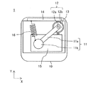
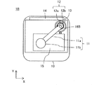
- FIG. 1 is a front view showing the configuration of the electromechanical device 1 according to the first embodiment.
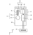
- FIG. 2 is a side view showing the configuration of the electromechanical device 1 of FIG.
- the electromechanical device 1 includes a housing 10, a pendulum 11, a gear mechanism 12, a generator 13, a frame 14, a power conversion circuit 15, an elastic body 16, and a fixture 17.
- the electromechanical device 1 is, for example, a wearable device worn on the user's body.
- the electromechanical device 1 generates electric power according to the vibration of the whole, and supplies the generated electric power to the load device 21.
- the pendulum 11 is connected, that is, fitted or integrated with the input shaft 12a (described later) of the gear mechanism 12.
- the pendulum 11 reciprocates around the input shaft 12a of the gear mechanism 12 within at least a predetermined angle range in response to the overall vibration of the electromechanical device 1.
- the torque generated by the pendulum 11 is transmitted to the gear mechanism 12 via the input shaft 12a.
- the pendulum 11 includes, for example, an arm 11a connected to the input shaft 12a of the gear mechanism 12 and a weight 11b connected to the arm 11a.
- the weight 11b may be iron, lead, synthetic resin (plastic or the like), stone, sand, liquid (water or the like), coins, or the like.
- the arm 11a and the weight 11b may be fixedly connected to each other by screwing, bonding, welding or the like. As a result, the force acting on the weight 11b can be effectively transmitted as torque to the gear mechanism 12.
- the arm 11a and the weight 11b may be movably connected to each other by a connecting member such as an elastic body or a ring. As a result, the force acting on the weight 11b is indirectly transmitted to the arm 11a via the connecting member, so that the magnitude of the torque and the length of time to be transmitted can be adjusted.
- the connecting member can be appropriately configured according to the application of the electromechanical device 1 and according to the load device 21.
- the pendulum 11 may be integrally formed as a single member.
- the gear mechanism 12 has an input shaft 12a, a housing 12b, and an internal gear (not shown), and transmits the rotation of the input shaft 12a to the generator 13.
- the gear mechanism 12 may be configured to transmit the rotation of the input shaft 12a to the generator 13 at a predetermined acceleration ratio.
- the gear mechanism 12 may include a multi-stage planetary gear mechanism. In this case, the gear mechanism having a large acceleration ratio can be aligned with the input shaft 12a of the generator 13 and incorporated compactly.
- the gear mechanism 12 may include a spur gear mechanism or another gear mechanism.
- the generator 13 includes a stator, a rotor, and a gear fixed to the rotating shaft of the rotor.
- the rotation transmitted from the gear mechanism 12 is input to the generator 13 via the gear.
- the generator 13 has a pair of output terminals, and generates electric power from the output terminals according to the rotation transmitted by the gear mechanism 12.
- the generator 13 may be a DC generator or an AC generator.
- the gear mechanism 12 and the generator 13 may be integrally configured.
- gear mechanism 12 having a predetermined speed increase ratio
- generator 13 a motor and a gear mechanism having a predetermined reduction ratio may be used.
- the gear mechanism transmits the rotation of the output shaft to the motor at an increase ratio that is the reciprocal of the reduction ratio.
- the motor then generates electric power in response to the rotation transmitted by the gear mechanism.
- the frame 14 is provided so that the positions relative to the gear mechanism 12 and the generator 13 are fixed.
- the relative position is fixed means that the position is directly or indirectly fixed so that the relative position with respect to the gear mechanism 12 and the generator 13 does not change.
- the elastic body 16 supports the pendulum 11 with respect to the frame 14 so as to generate a restoring force to a predetermined position.
- the elastic body 16 is a coil spring, one end of which is connected to the arm 11a or the weight 11b of the pendulum 11, and the other end is connected to the frame 14.
- one end of the elastic body 16 is connected to the weight 11b, but it may be connected to the arm 11a instead of the weight 11b.
- FIG. 1 shows a steady state of the pendulum 11. In the example of FIG.
- the pendulum 11 is supported by the elastic body 16 so that the weight of the pendulum 11 and the restoring force of the elastic body 16 are balanced and stationary at a position higher than the lowest position in the steady state.
- the elastic body 16 When the pendulum 11 rotates clockwise or counterclockwise from the steady state position, the elastic body 16 generates a restoring force so that the pendulum 11 returns to the steady state position.
- the elastic body 16 expands and contracts in the same plane as the plane including the locus of the pendulum 11 (that is, the plane perpendicular to the input shaft 12a of the gear mechanism 12), the elastic body 16 can effectively give a restoring force to the pendulum 11. can.
- the frame 14 is formed so that the elastic body 16 can be connected so that the elastic body 16 expands and contracts in the same plane as the plane including the locus of the pendulum 11.
- the elastic body 16 may be directly connected to the frame 14 or may be indirectly connected via another member.
- the power conversion circuit 15 rectifies and / or stores the electric power generated by the generator 13 for use by the load device 21 in the subsequent stage.
- the load device 21 operates by the electric power generated by the generator 13.
- the load device 21 includes, for example, at least one of a lighting device, a rechargeable battery, a motor, a sensor, and a wireless communication device.
- the housing 10 surrounds the pendulum 11, the gear mechanism 12, the generator 13, the frame 14, the power conversion circuit 15, and the elastic body 16.
- the housing 10 may be provided so that its position relative to the gear mechanism 12, the generator 13, and the frame 14 is fixed.
- one end of the elastic body 16 may be connected to the housing 10 instead of being connected to the frame 14.
- the power conversion circuit 15 may be omitted, may be provided outside the housing 10, or may be integrated with, for example, the load device 21. 1 and 2 show the housing 10 as a broken view for the sake of explanation.
- the attachment 17 is provided to attach the electromechanical device 1 to a movable external object (hereinafter, also referred to as a “movable object”).
- the fixture 17 is fixed to the generator 13, the frame 14, or the housing 10.
- a "movable object” may refer to a human or animal body, an article worn or held by a human or animal, a mechanical device, or by wind or hydraulic power. It may indicate an article to be deformed.
- the electromechanical device 1 is attached to the movable object by the attachment 17 so that the electromechanical device 1 follows the movement of the movable object.
- the fixture 17 may be configured to be inserted into, for example, a belt or clothing, or sandwiched.
- the fixture 17 may be composed of one member, or may be composed of a plurality of members including a spring or the like. Further, the attachment 17 may be a safety pin or a hook-and-loop fastener that can be attached to clothes, or an adhesive tape that can be attached to clothes or skin. Further, the attachment 17 may be a belt or a string that can be wrapped around an arm, a leg, a torso, or the like. Further, the attachment 17 may be a string that can be tied to a shoelace or the like. If the moving object is inanimate, the fixture 17 may include screws.
- the attachment 17 may be omitted.
- the pendulum 11 reciprocates around the input shaft 12a of the gear mechanism 12 according to the overall vibration of the electromechanical device 1 or the restoring force of the elastic body 16, and the generator 13 reciprocates the pendulum 11. Generates power according to.
- the electromechanical device 1 By attaching the electromechanical device 1 to a movable object, the electromechanical device 1 follows the movement of the movable object and vibrates as a whole. Acceleration or deceleration of a moving object causes a force such as inertial force and centrifugal force to be generated in the pendulum 11, and this force causes the pendulum 11 to move with reference to the position of the pendulum 11 when the moving object is stationary or linearly moving at a constant velocity. Displace or vibrate.
- the force acting when the stationary pendulum 11 starts to move and the force acting when the moving pendulum 11 moves stationary or in the opposite direction are referred to as "inertial force". Since most of the movements of moving objects such as humans or objects are accompanied by acceleration and deceleration, the inertial force and centrifugal force acting on the weight 11b at this time can be utilized. Even if the force acting on the weight 11b is small, a large torque can be transmitted to the gear mechanism 12 and the generator 13 via the arm 11a by the principle of the lever. In this way, the pendulum 11 reciprocates around the input shaft 12a of the gear mechanism 12 in response to the overall vibration of the electromechanical device 1, and the generator 13 positively reciprocates in the output terminal in response to the reciprocation of the pendulum 11. And generate a negative voltage. The electric power generated by the generator 13 is supplied to the load device 21 via the power conversion circuit 15.
- FIG. 3 is a circuit diagram showing the configuration of the power conversion circuit 15 of FIG.
- the power conversion circuit 15 includes a rectifier circuit 31, a power storage circuit 32, and a control circuit 33.
- the rectifier circuit 31 rectifies the electric power generated by the generator 13. Even if the generator 13 is a DC generator, when the pendulum 11 advances in one direction and in the opposite direction, the rotation direction of the generator 13 is opposite and a voltage of opposite polarity is generated. Rectification is required to store power in a capacitor or secondary battery.
- the power storage circuit 32 includes at least one capacitor that stores the energy of the electric power rectified by the rectifier circuit 31.
- the control circuit 33 controls the discharge of the power storage circuit 32.
- the control circuit 33 may include, for example, an active booster circuit including a power transistor or the like, and may control the discharge of the power storage circuit 32 according to the operation of the load device 21.
- the rectifier circuit 31 includes two diodes D1 and D2.
- the power storage circuit 32 includes two capacitors C1 and C2.
- the control circuit 33 includes capacitors C3 to C6, diodes D3 to D5, coils L1, resistors R1 to R6, variable resistors VR1, transformers TF1, and transistors TR1 to TR5.
- the load device 21 includes a light emitting diode (LED).
- the diodes D1 and D2 and the capacitors C1 and C2 form a voltage doubler rectifier circuit that performs voltage doubler rectification of the voltage generated by the generator 13.
- a voltage doubler rectifier circuit that performs voltage doubler rectification of the voltage generated by the generator 13.
- the circuit in the subsequent stage of the power storage circuit 32 (that is, the control circuit 33 and the load device 21) can be operated at a high voltage, and the efficiency of the circuit in the subsequent stage can be improved.
- full-wave rectification only the same power generation voltage can be obtained when the pendulum 11 moves to the right and when the pendulum 11 moves to the left. Therefore, even if the power generation time is doubled, the stored energy is increased. Can't.
- Capacitors C1 and C2 are, for example, electrolytic capacitors. Further, the capacitors C1 and C2 may be electric double layer capacitors, secondary batteries, or the like.
- the capacitors C3 to C5, the diodes D3, the resistors R1 to R6, the transformer TF1, and the transistors TR2 to TR5 form the inverter circuit 33a.
- the inverter circuit 33a operates in a voltage resonance type and performs soft switching (zero volt switching).
- the capacitor C3, the resistor R1, the variable resistor VR1, and the transistors TR1 to TR3 form a voltage setting circuit 33b.
- the voltage setting circuit 33b uses the variable resistor VR1 and the transistor TR1 to set the voltage range in which the electromechanical device 1 operates, particularly the lower limit voltage of the output voltage of the power storage circuit 32.
- the control circuit 33 supplies power from the power storage circuit 32 to the load device 21 (light emitting diode) when the voltage across the capacitors C1 and C2 of the power storage circuit 32 is equal to or lower than the lower limit voltage set in the voltage setting circuit 33b. Stop. Further, the capacitors C3, C5, the resistors R1 to R3, R5, R6, the transformer TF1, and the transistors TR2, TR3, TR5 form a constant current control circuit 33c.
- the control circuit 33 sets a lower limit voltage in the power storage circuit 32. For example, it is assumed that the generated voltage (induced electromotive force, rate electromotive force) at the time of power generation per generator 13 is 12 (V).
- the control circuit 33 may be omitted when the lower limit voltage is not set in the power storage circuit 32. Further, the load device 21 may be provided with a control circuit that controls the discharge of the power storage circuit 32 according to the operation of the load device 21.
- the force generated by the acceleration and deceleration of a moving object such as a human being is used, and the efficient recovery of mechanical energy is attempted, including the combined use with gravity and centrifugal force.
- the output voltage of the generator 13 is higher in order to increase the stored electric energy or drive an arbitrary load device. Therefore, it is important to increase the speed increase ratio of the gear mechanism 12 and increase the counter electromotive voltage constant (an index that generates a high induced voltage at low speed rotation) of the generator 13.
- the counter electromotive voltage constant an index that generates a high induced voltage at low speed rotation
- a multiple voltage rectification such as a rectification and a voltage doubler rectification using electricity storage, which can be used when the generator 13 generates an AC output voltage (many). Double voltage rectification) is effective.
- the generator 13 repeats forward rotation and reverse rotation according to the reciprocation of the pendulum 11, and continuously generates an AC voltage including positive and negative voltages at the output terminal. Mechanical energy can be efficiently recovered by performing double voltage rectification (double voltage rectification) from this AC voltage. Further, by connecting three or more capacitors in series in the power storage circuit 32, further multiple times voltage rectification of 3 times, 4 times, ... May be performed.
- the output voltage of the power storage circuit 32 can be increased, and the amount of power stored in the power storage circuit 32 can be increased. Further, when the power conversion circuit 15 or the load device 21 includes a booster circuit, the efficiency of the booster circuit can be improved by increasing the voltage before boosting by voltage doubler rectification. As described above, according to the power conversion circuit 15 of FIG. 3, the overall efficiency of the electromechanical device 1 is improved by performing the voltage doubler rectification.
- the power conversion circuit 15 temporarily stores the electric power generated by the generator 13 in the power storage circuit 32, and the power storage amount of the power storage circuit 32 represents a sufficient amount for operating the load device 21.
- the electric power stored in the power storage circuit 32 may be supplied to the load device 21.
- the control circuit 33 is omitted, the power conversion circuit 15 may supply the electric power generated by the generator 13 to the load device 21 in real time.
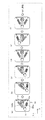
- FIG. 4 is a diagram illustrating the operation of the electromechanical device 1 of FIG.
- the pendulum 11 of the gear mechanism 12 responds to the vibration of the electromechanical device 1 in the horizontal direction (X direction) and / or the vertical direction (Y direction). It reciprocates around the input shaft 12a.
- the pendulum 11 is in the steady state position.
- the elastic body 16 is stretched more than in the steady state, and a restoring force is generated so that the pendulum 11 returns to the position in the steady state.
- FIG. 4B the elastic body 16 is stretched more than in the steady state, and a restoring force is generated so that the pendulum 11 returns to the position in the steady state.
- the elastic body 16 is compressed more than in the steady state, and a restoring force is generated so that the pendulum 11 returns to the position in the steady state. Therefore, the pendulum 11 reciprocates around the input shaft 12a of the gear mechanism 12 according to the vibration of the entire electromechanical device 1 or the restoring force of the elastic body 16.
- FIG. 5 is a front view showing the configuration of the electromechanical device 2 according to the comparative example.
- FIG. 6 is a side view showing the configuration of the electromechanical device 2 of FIG.
- the electromechanical device 2 has a configuration in which the elastic body 16 is substantially removed from the electromechanical device 1 of FIG.
- the pendulum 11 of the electromechanical device 2 reciprocates around the input shaft 12a of the gear mechanism 12 exclusively in response to the horizontal vibration of the electromechanical device 2.
- the pendulum 11 of the electromechanical device 1 is connected to the elastic body 16 in the vertical direction of the electromechanical device 1. It is easy to reciprocate around the input shaft 12a according to the vibration. Therefore, the electromechanical device 1 according to the embodiment can effectively generate electric power from vibration, rocking, impact, and the like of the electromechanical device 1 including a directional component other than the horizontal direction.
- the pendulum 11 not only moves by receiving the horizontal vibration of the electromechanical device 1, but also moves by receiving the vertical vibration of the electromechanical device 1. Therefore, according to the electromechanical device 1 according to the embodiment, the direction of the force acting on the movement of the pendulum 11 can be increased, that is, the opportunity to generate electric power can be increased as compared with the electromechanical device 2 according to the comparative example, and as a result. , The amount of power generated and the amount of power can be increased. According to the electromechanical device 1 according to the embodiment, for example, power can be effectively generated from a stepping motion on the spot or from a vertical motion such as "standing up” or “sitting" in daily life. ..
- the pendulum 11 can move by receiving not only a force in a direction orthogonal to a straight line passing through an input shaft 12a and a weight 11b of a gear mechanism 12 but also a force in an oblique direction, and such an oblique force also contributes to power generation. Can be made to. In other words, the pendulum 11 can move by receiving the force of an arbitrary directional component in the plane (XY plane in FIG. 1) perpendicular to the input shaft 12a.
- the electromechanical device 1 may be arranged in various postures, not limited to the postures shown in FIGS. 1 and 2.
- the weight 11b of the pendulum 11 receives kinetic energy by accelerating and decelerating due to movements such as walking or posture change of a human.
- the kinetic energy of the weight 11b is converted into the potential energy of gravity applied to the weight 11b as a change in the position and angle of the weight 11b, and the potential energy is converted into the kinetic energy again.
- the electromechanical device 1 includes the elastic body 16, the kinetic energy and potential energy of the weight 11b are also converted into the elastic energy of the elastic body 16, and the elastic energy of the elastic body 16 is again the kinetic energy and potential energy of the weight 11b. Is converted to.
- the pendulum 11 reciprocates while repeating mutual conversion of kinetic energy, potential energy, and elastic energy, and power generation is continued.
- the period of the pendulum 11 is determined in consideration of the mechanical load of the gear mechanism 12 and the electrical load of the generator 13 and the subsequent circuits (that is, the power conversion circuit 15 and the load device 21). Therefore, the period of the pendulum 11 is measured by connecting the load device 21 to the generator 13, and the elastic body 16 has a natural period equal to the period of the pendulum 11 when the load device 21 is connected to the generator 13.
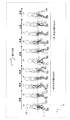
- FIG. 7 is a diagram illustrating the relationship between the walking of the user 100 and the pendulum 11 of the electromechanical device 1 of FIG.
- the example of FIG. 7 shows a case where the electromechanical device 1 is attached to the side of the waist of the user 100 and power is generated by walking of the user 100.
- the pendulum 11 is exposed to the outside of the electromechanical device 1 and enlarged, and the right foot of the user 100 is shown by hatching for explanation.
- Walking is generally considered to be a repetition of acceleration, deceleration, and constant velocity periods. In this case, when the foot and pendulum 11 of the user 100 are at the positions shown in FIGS.
- the electromechanical device 1 is configured so that the period of the pendulum 11, the natural period of the elastic body 16, and the acceleration / deceleration period of the walking user 100 coincide with each other.
- the natural period of the elastic body 16 does not have to completely match the period of the pendulum 11, and if it has a value in the vicinity of the period of the pendulum 11, it may generate sufficient electric power for practical use. can.
- the electromechanical device 1 when the electromechanical device 1 is attached to the body of the user 100, electric power can be continuously and stably generated by the continuous operation of the user 100 such as walking.
- the electromechanical device 1 can generate electric power of several tens of mW to several W or more, and can generate energy of several J to 10,000 J by walking for several minutes to several hours such as commuting or shopping. can.
- a user 100 equipped with an electromechanical device 1 that generates 1 W of electric power walks for 2 hours
- 23 cc of water at 25 degrees can be heated up to 100 degrees.
- the electromechanical device 1 prototyped by the present inventor is attached to the body of the user 100, it is possible to generate energy for lighting an LED flashlight for several seconds to several tens of seconds by walking for several seconds.
- the electromechanical device 1 when the electromechanical device 1 is attached to the body of the user 100, the electromechanical device 1 is subjected to a short-time movement (for example, a momentary movement) or a small movement of the user 100, such as turning, standing up / sitting, raising and lowering limbs, and turning over. Can generate electricity.
- the electromechanical device 1 has sufficient power, for example, several tens of mW, to operate a circuit having a small power consumption such as a sensor and / or a wireless communication device even from a short operation or a small operation of the user 100. It can generate power of up to several watts.
- a highly efficient power generation system is required.
- a power generation system having sufficient utility value is provided even in a slow walking of the user and a normal walking such as when the user commute.
- the "sufficiently useful power generation system” means that, for example, electric power corresponding to the brightness of an LED flashlight carried by a user when walking at night can be reasonably generated.
- a general communication circuit, a sensor circuit, or the like can be sufficiently operated.
- “reasonably” means that the user is not aware of excessive exercise for power generation and does not cause a sense of discomfort that he or she is wearing. This makes it possible to realize a compact and lightweight wearable power generation system.
- the pendulum 11 Since the electromechanical device 1 is provided with the housing 10, the pendulum 11 does not come into contact with the clothes and / or the body (for example, a hand) of the user 100, and therefore, while the movable object is moving, the pendulum 11
- the reciprocating operation can be continued without hindrance.
- the electromechanical device 1 is attached to the belt or clothes of the user 100, the reciprocating operation of the pendulum 11 is not hindered even if a jacket or the like is further worn over the electromechanical device 1. Further, even when the electromechanical device 1 is inserted into a pocket or the like, the reciprocating operation of the pendulum 11 is not hindered.
- electric power can be continuously and unconsciously taken out from the daily activities of the user 100 such as walking, turning, standing / sitting, raising and lowering limbs, and turning over. Since the power generation can be continued without hindrance while the movable object is moving, it is possible to extract a relatively large amount of power from the daily activities of the user 100.
- the electromechanical device 1 although it can be arranged in various postures, it is possible to continuously and unconsciously generate a larger amount of electric power than before due to the user's daily activities and the like at more opportunities than before. Can be taken out.
- FIG. 8 is a diagram showing a first usage example of the electromechanical device 1 of FIG.
- the electromechanical device 1 may be configured to be attached to the body of the user 100.
- the generator 13 generates electric power according to the movement of the body of the user 100.
- the electromechanical device 1 may be attached to the belt 41 wrapped around the body of the user 100 by, for example, a fitting 17.
- the belt 41 may be wrapped around the torso (waist, etc.), upper arm, forearm, wrist, upper thigh, lower leg, ankle, etc. of the user 100, for example.
- the belt 41 may be provided in the electromechanical device 1 instead of the attachment 17 in FIG. In this way, by attaching the electromechanical device 1 to the belt 41 or clothes directly worn by the user 100, it is possible to easily and reasonably generate electricity according to the physical movement of the user 100.
- FIG. 8 shows a case where the load device 21 is a lighting device.
- the load device 21 is a lighting device.
- FIG. 9 is a diagram showing a second usage example of the electromechanical device 1 of FIG.
- FIG. 10 is a diagram showing a third use example of the electromechanical device 1 of FIG.
- the electromechanical device 1 may be configured to be attachable to an article worn or held by the user 100.
- the generator 13 generates electric power according to the movement of the article.
- the electromechanical device 1 may be inserted into, for example, a shoulder-mounted bag 42 as shown in FIG. 9, or may be inserted into a trunk 43 with casters as shown in FIG. Further, the electromechanical device 1 may be attached to the outside of the bag 42 and the trunk 43 by the attachment 17. Further, the electromechanical device 1 may be attached to a carrying bag, a knapsack, a suitcase, a shopping cart, or the like.
- the physical movement of the user 100 also causes the article held or used by the user 100 to move. Therefore, by attaching the electromechanical device 1 to the article indirectly used by the user 100, it is possible to easily and reasonably generate electricity according to the physical movement
- FIGS. 9 and 10 show a case where a rechargeable battery 22 is connected to the electromechanical device 1 as a load device.
- the swing of the user 100's body in the front-back and up-down directions due to walking is transmitted to the bag 42, and the swing of the bag 42 is used. It can generate electricity effectively.
- the swing of the trunk 43 due to the unevenness or step of the road surface, or the swing of the trunk 43 due to walking is transmitted to the trunk 43.
- the swing of the trunk 43 can be used to effectively generate electricity.
- the electromechanical device 1 can charge, for example, a battery 22 of a mobile phone or the like.
- the electromechanical device 1 since the force for swinging the pendulum 11 can be obtained from the body of the user 100, it is possible to reliably generate electricity when the body of the user 100 moves.
- the electromechanical device 1 can generate electricity from the continuous movement of the body of the user 100 or from a short and temporary movement.
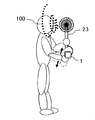
- FIG. 11 is a fourth use example of the electromechanical device 1 of FIG. 1, and is a diagram for explaining power generation when the user 100 is walking.
- FIG. 12 is a fourth use example of the electromechanical device 1 of FIG. 1, and is a diagram for explaining power generation when the user 100 is stopped.
- the examples of FIGS. 11 and 12 show a case where a portable electric fan 23 is connected to the electromechanical device 1 as a load device. For example, the user 100 puts the electromechanical device 1 on the palm of his right hand and holds the electric fan 23 on his left hand.
- the electromechanical device 1 is configured to be able to be held by one hand of the user 100.
- the electromechanical device 1 can be configured to have a weight of several tens of grams to several hundreds of grams and a size of about 2 cm to 30 cm, for example.
- the electromechanical device 1 may be configured to have a size of, for example, about 5 cm to 10 cm when placed on one hand. Even with such weight and size, the electromechanical device 1 can generate sufficient electric power to operate a desired load device.
- the generator 13 of the electromechanical device 1 generates electric power in response to the movement of one hand having an arbitrary directional component in a plane perpendicular to the input shaft 12a.
- the palm of the right hand is lightly and naturally moved up and down in accordance with the rhythm of the up and down shaking accompanying the walking of the user 100, and the electromechanical device 1 moves the hand. Can be used to generate electricity without difficulty.
- the user 100 even when the user 100 is stopped, the user 100 lightly shifts the electromechanical device 1 in various directions such as a front-rear direction, a vertical direction, or a direction along the circumference. It can generate electricity by swinging.
- the electromechanical device 1 can drive the motor by supplying the electric power generated by the generator 13 to the motor of the electric fan 23 in real time. Further, the electromechanical device 1 may temporarily store the electric power generated by the generator 13 in the power storage circuit 32 and supply the electric power from the power storage circuit 32 to the motor of the electric fan 23 to drive the motor. According to the electromechanical device 1, since a relatively large amount of electric power can be reasonably generated by a light operation with one hand, it is possible to drive a load device that requires a large starting current such as a motor. Therefore, the electromechanical device 1 can also directly drive, for example, the motor of the electric fan 23 that does not have a battery. By slightly shaking the hand holding the electromechanical device 1 as the user 100 walks, it is possible to unconsciously and continuously generate wind without feeling any effort. Further, even when the user 100 is stopped, the wind can be continuously generated by shaking the hand holding the electromechanical device 1.
- the electromechanical device 1 can effectively generate power only by moving one hand, the power generation device can be placed on the palm of one hand or hung as necessary even when the body of the user 100 does not move much. Or, by attaching one hand and actively shaking it lightly, it is possible to generate electricity continuously. If the electromechanical device 1 is shaken strongly, the generated electric power and the amount of electric power (or the amount of electricity stored) also increase. In this way, when necessary, the electromechanical device 1 can be used to easily generate electricity.
- the electromechanical device 1 may supply electric power to the load device 21 including a sensor for measuring biological information such as pulse, respiration, body temperature, and / or blood pressure of the user 100, for example.
- the electromechanical device 1 measures the pulse, respiration, and / or blood pressure of the user 100 in real time, for example, while the user 100 is walking, and, if necessary, measures the measurement result of the load device 21.
- the load device 21 can be operated so as to notify other devices. Thereby, the physical condition of the user 100 can be managed.
- the electromechanical device 1 may supply electric power to the load device 21 including, for example, a wireless communication device capable of receiving GPS signals.
- the electromechanical device 1 can operate the load device 21 so as to constantly or periodically obtain the position information of the user 100.
- the electromechanical device 1 may supply electric power to a load device 21 including a wireless communication device capable of transmitting a polling signal to a receiver in the home of the user 100, for example.
- the receiver in the house may notify the status of the user 100 to the relatives of the user 100 who live in a remote place.
- FIG. 13 is a front view showing the configuration of the electromechanical device 1A according to the first modification of the first embodiment.
- FIG. 14 is a side view showing the configuration of the electromechanical device 1A of FIG.
- the electromechanical device 1A includes a pair of elastic bodies 16Aa and 16Ab connected to both sides of the pendulum 11 in place of the elastic body 16 of FIG.
- FIG. 15 is a diagram illustrating a first operation example of the electromechanical device 1A of FIG.
- the pendulum 11 of the gear mechanism 12 responds to the vibration of the electromechanical device 1A in the horizontal direction (X direction) and / or the vertical direction (Y direction). It reciprocates around the input shaft 12a.
- the pendulum 11 is in the steady state position.
- the elastic body 16Aa is stretched more than in the steady state, the elastic body 16Ab is compressed more than in the steady state, and the restoring force is applied so that the pendulum 11 returns to the steady state position. Occurs.
- FIG. 15B the elastic body 16Aa is stretched more than in the steady state, the elastic body 16Ab is compressed more than in the steady state, and the restoring force is applied so that the pendulum 11 returns to the steady state position. Occurs. Further, in the case of FIG.
- the elastic body 16Aa is compressed more than in the steady state, the elastic body 16Ab is stretched more than in the steady state, and the restoring force is applied so that the pendulum 11 returns to the steady state position. Occurs. Therefore, the pendulum 11 reciprocates around the input shaft 12a of the gear mechanism 12 according to the overall vibration of the electromechanical device 1A or the restoring force of the elastic body 16.
- FIG. 16 is a diagram illustrating a second operation example of the electromechanical device 1A of FIG.
- the electromechanical device 1A is provided rotated by 90 degrees from the case of FIG.
- the pendulum 11 of the gear mechanism 12 responds to the vibration of the electromechanical device 1A in the horizontal direction (X direction) and / or the vertical direction (Y direction). It reciprocates around the input shaft 12a.
- the weight of the pendulum 11 and the restoring force of the elastic bodies 16Aa and 16Ab are balanced, and the pendulum 11 is in a steady state position. Further, in the case of FIG.
- the elastic body 16Aa is compressed more than in the steady state, the elastic body 16Ab is stretched more than in the steady state, and the restoring force is applied so that the pendulum 11 returns to the steady state position. Occurs.
- the elastic body 16Aa is stretched more than in the steady state, the elastic body 16Ab is compressed more than in the steady state, and the restoring force is applied so that the pendulum 11 returns to the steady state position. Occurs.
- the elastic bodies 16Aa and 16Ab do not generate a restoring force, but the pendulum 11 is pulled by gravity and tries to return to the steady state position. Therefore, the pendulum 11 reciprocates around the input shaft 12a of the gear mechanism 12 according to the overall vibration of the electromechanical device 1A or the restoring force of the elastic body 16.
- the electromechanical device 1A by providing the pair of elastic bodies 16Aa and 16Ab, the electromechanical device 1A can be arranged with a higher degree of freedom in terms of posture than in the case of the electromechanical device 1 of FIG.
- FIG. 17 is a front view showing the configuration of the electromechanical device 1B according to the second modification of the first embodiment.
- FIG. 18 is a side view showing the configuration of the electromechanical device 1B of FIG.
- the electromechanical device 1B includes an elastic body 16B which is a torsion spring instead of the elastic body 16 of FIG. 1 which is a coil spring.
- the elastic body 16B is provided around the input shaft 12a of the gear mechanism 12. One end of the elastic body 16B is connected to the pendulum 11, and the other end is connected to the housing 12b of the gear mechanism 12. Since the relative position of the gear mechanism 12 with respect to the frame 14 is fixed, the elastic body 16B is indirectly connected to the frame 14 by being connected to the housing 12b of the gear mechanism 12.
- the electromechanical device 1B as in the electromechanical device 1 of FIG. 1, it can be arranged in various postures, but on more occasions than before, a larger amount of electric power is generated from the user's daily activities and the like. It can be taken out continuously and unconsciously.
- FIG. 19 is a front view showing the configuration of the electromechanical device 1C according to the third modification of the first embodiment.
- the electromechanical device 1C may further include a load device 21 in addition to each component of the electromechanical device 1 of FIG. By integrating the load device 21 into the electromechanical device 1C, its convenience is improved.
- FIG. 20 is a front view showing the configuration of the electromechanical device 1D according to the fourth modification of the first embodiment.
- the electromechanical device 1D has a configuration in which the electromechanical device 1 and the electric fan 23 of FIGS. 11 and 12 are integrated. Similar to the electromechanical device 1 of FIGS. 11 and 12, the electromechanical device 1D can generate electricity by lightly moving the arm in accordance with the rhythm of the swing accompanying the walking of the user 100, and the user 100 stops. Even when the user 100 is operating, the user 100 can swing the electromechanical device 1 to continue power generation.
- the electromechanical device according to the embodiment is not limited to the fan 23, and any load device can be incorporated.
- FIGS. 21 to 33 show a case where the load device 21 of the electromechanical device 1C is a wireless communication device, and when the electromechanical device 1C generates electric power, the wireless communication device uses the generated electric power.
- the server device 61 is provided, for example, at the home of the user 100, a hospital, another facility, or the like.
- the wireless communication device transmits a wireless signal including, for example, a polling signal or another signal (for example, a detection signal of a sensor that measures the pulse or respiration of the user 100) to the server device 61.
- FIG. 21 is a diagram showing a first usage example of the electromechanical device 1C of FIG.
- FIG. 22 is a diagram showing a second usage example of the electromechanical device 1C of FIG.
- FIG. 23 is a diagram showing a third use example of the electromechanical device 1C of FIG.
- the electromechanical device 1C is suspended from a part of the body of the user 100 (for example, neck or shoulder) by, for example, a strap 45.
- the electromechanical device 1C is inserted, for example, into a pocket 46 of clothing. Further, the electromechanical device 1C may be attached to clothing by using, for example, a safety pin.
- FIG. 21 is a diagram showing a first usage example of the electromechanical device 1C of FIG.
- FIG. 22 is a diagram showing a second usage example of the electromechanical device 1C of FIG.
- FIG. 23 is a diagram showing a third use example of the electromechanical device 1C of FIG.
- the electromechanical device 1C is suspended from a part of the body of the user
- the electromechanical device 1C is attached to the shoe 47 using, for example, a fitting 17 or a shoelace.
- the swing of the user 100's body in the front-back, left-right, and up-down directions due to walking or the like is transmitted to the electromechanical device 1C, and the swing of the electromechanical device 1C is used to effectively generate electricity. can do.
- FIG. 24 is a diagram showing a fourth use example of the electromechanical device 1C of FIG.
- FIG. 25 is a diagram showing a fifth use example of the electromechanical device 1C of FIG.
- the electromechanical device 1C is attached to, for example, a hat 48. Further, in the example of FIG. 25, the electromechanical device 1C is attached to, for example, eyeglasses 49.
- the back-and-forth, left-right, and up-down swings of the user 100's head due to walking or turning motion are transmitted to the electromechanical device 1C when going out or other daily activities, and the electric machine It is possible to effectively generate electricity by utilizing the swing of the device 1C.
- FIG. 26 is a diagram showing a sixth use example of the electromechanical device 1C of FIG.
- the electromechanical device 1C is attached to, for example, a belt 41 or a helmet 50.
- the swing of the user 100's body in the front-back, left-right, and up-down directions is transmitted to the electromechanical device 1C, and the swing of the electromechanical device 1C is effectively used. It can generate electricity.
- the wireless communication device of the electromechanical device 1C can, for example, notify the server device 61 of the information of the user 100 or the work information.
- FIG. 27 is a diagram showing a seventh usage example of the electromechanical device 1C of FIG.
- FIG. 28 is a diagram showing an eighth use example of the electromechanical device 1C of FIG.
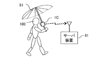
- the electromechanical device 1C is attached to, for example, an umbrella 51.
- the swing of the umbrella 51 due to the walking of the user 100 is transmitted to the electromechanical device 1C, and the swing of the electromechanical device 1C is used to effectively generate electricity. can.
- the electromechanical device 1C is attached to, for example, a cane 52.
- a cane 52 In the example of FIG.
- FIG. 29 is a diagram showing a ninth use example of the electromechanical device 1C of FIG.
- FIG. 30 is a diagram showing a tenth use example of the electromechanical device 1C of FIG.
- FIG. 31 is a diagram showing an eleventh use example of the electromechanical device 1C of FIG.
- the electromechanical device 1C is worn on the body of the user 100 using the belt 41.
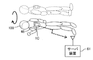
- the electromechanical device 1C is inserted into a pocket 46 provided in the clothes of the user 100.
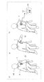
- the electromechanical device 1C generates electric power in response to raising and lowering limbs (FIG. 29), standing up / sitting (FIG. 30), turning over (FIG.
- the load device 21 is operated so as to transmit the signal to the server device 61.
- the swing caused by the short-time and temporary operation of the user 100 is transmitted to the electromechanical device 1C, and the swing of the electromechanical device 1C can be used to effectively generate electricity.
- the electromechanical device 1C repeats power generation for one or several times to store electric power in the power storage circuit 32, and a predetermined threshold value indicating that the amount of power stored in the power storage circuit 32 is sufficient for operating the load device 21. When it reaches, the electric power stored in the power storage circuit 32 is supplied to the load device 21. Thereby, for example, the state of the user 100 can be monitored (watched).
- the electromechanical device 1 may be configured to be attached to the user 100 or the body of an animal.
- the generator 13 generates electric power according to the movement of the user 100 or the body of the animal.
- the electromechanical device 1 may be configured to be attached to an article worn or held by the user 100 or an animal. In this case, the generator 13 generates electric power according to the movement of the article.
- the physical exercise of the user 100 also causes the article owned or used by the user 100 to exercise. Therefore, by attaching the electromechanical device 1 to an object indirectly used by the user 100, it is possible to easily and reasonably generate electricity according to the physical movement of the user 100.
- the electromechanical device 1C since the force for swinging the pendulum 11 can be obtained from the body of the user 100, it is possible to reliably generate electricity when the body of the user 100 moves.
- the electromechanical device 1C can generate electricity from the continuous movement of the body of the user 100 or from a short and temporary movement. Therefore, the generated electric power can be used to operate the lighting device or the motor in real time or to charge the battery of the mobile phone or the like.
- the load device 21 may include, for example, a biometric information sensor, a positioning device, a camera, or the like in addition to the wireless communication device.
- the electromechanical device 1C directly or once stores the generated electric power in the power storage circuit 32 and supplies it to the load device 21.
- the data acquired by the sensor, the positioning device, or the camera is transmitted to the server device 61 by the wireless communication device.
- the server device 61 can acquire information such as the presence / absence of the behavior of the user 100, the type of behavior, the position information, and the image.
- the electromechanical device 1C can be used for watching over the elderly, preventing children from getting lost, and the like.
- the electromechanical device 1C can be attached not only to the clothes of the user 100, but also to various articles such as an article held by the user 100 in his hand, an article carried on his back, and an article to be pulled. As a result, the movement of the user 100 is transmitted to the electromechanical device 1C via the article, and the swing of the electromechanical device 1C can be used to effectively generate electricity.
- FIG. 32 is a diagram showing a twelfth usage example of the electromechanical device 1C of FIG.
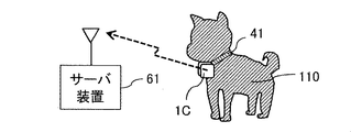
- the electromechanical device 1C may be configured to be attachable to the body of the animal 110.
- the generator 13 generates electric power according to the movement of the body of the animal 110.
- the electromechanical device 1C may be configured to be attachable to an article mounted on the animal 110. In this case, the generator 13 generates electric power according to the movement of the article.
- the electromechanical device 1C is attached to the body of the animal 110 using the belt 41.
- the belt 41 may be, for example, a collar or a strap around the neck.
- the electromechanical device 1C since the force for swinging the pendulum 11 can be obtained from the body of the animal 110, it is possible to reliably generate electricity when the body of the animal 110 moves.
- the electromechanical device 1C can generate electricity from the continuous movement of the body of the animal 110 or from a short and temporary movement.
- the lighting device By attaching the electromechanical device 1C to the neck or back of the pet in a wearable manner, for example, the lighting device can be turned on during a walk at night to call attention to other pedestrians or vehicles. Further, by attaching the electromechanical device 1C to the grazing livestock, it is possible to track the number of livestock, individual behavior, individual position, etc., and manage the livestock in an integrated manner.
- FIG. 33 is a diagram showing a thirteenth use example of the electromechanical device 1C of FIG.
- FIG. 34 is a diagram showing a fifth use example of the electromechanical device 1 of FIG.
- the electromechanical devices 1 and 1C may be configured so as to be attached to the mechanical device.
- the generator 13 generates electric power according to the movement of the mechanical device.
- the example of FIG. 33 shows the case where the mechanical device is a washing machine 120.
- the electromechanical device 1C is attached to the housing of the washing machine 120 using a fixture 17 or other member (such as a magnet).
- the example of FIG. 34 shows the case where the mechanical device is a bicycle 130.
- FIG. 34 shows the case where the mechanical device is a bicycle 130.
- the electromechanical device 1 and the load device 21 which is a lighting device are attached to the fork of the front wheel of the bicycle 130 by a screw or the like is shown.
- the electromechanical device 1 may be attached to, for example, a pedal, a crank, a steering wheel, or the like of the bicycle 130 instead of the fork.
- the electromechanical devices 1 and 1C may be attached to a movable object that is moved by a power other than human power. Electromechanical devices 1 and 1C can be used for fuel-powered objects such as automobiles (for example, in the car, engine room, or car body) or trains (for example, hanging leather), motor-powered mechanical devices, vibrating mechanical devices in factories, and others. By attaching it to an object that moves with energy, it is possible to easily and reasonably generate electricity. Further, the electromechanical devices 1 and 1C may be attached to a door or a window moved by the user 100. By attaching the electromechanical devices 1, 1C to the mechanical device that causes vibration or rocking in this way, the vibration or rocking is transmitted to the electromechanical devices 1,1C, and the rocking of the electromechanical devices 1, 1C is utilized. And can generate electricity effectively.
- fuel-powered objects such as automobiles (for example, in the car, engine room, or car body) or trains (for example, hanging leather), motor-powered mechanical devices, vibrating mechanical devices in factories, and others.
- FIG. 35 is a diagram showing a sixth use example of the electromechanical device 1 of FIG.
- the electromechanical device 1 may be configured to be attachable to an article that is deformed by wind or hydraulic power.
- the generator 13 generates electric power according to the movement of the article.
- the electromechanical device 1 is attached to a branch of tree 140 using a fixture 17 or other member (eg, belt, strap, etc.).
- the branch deforms and swings in response to wind (wind power) or rain (hydraulic force), the swing of the branch is transmitted to the electromechanical device 1, and the swing of the electromechanical device 1 is used to effectively generate electricity. be able to.
- the example of FIG. 35 shows a case where the load device 21 is a lighting device, and the lighting device is turned on by the electric power generated when the branches are deformed and rocked by wind or rain to illuminate the trees.
- the electromechanical device 1 is attached to an article or place that receives wind, raindrops, or a stream of water so as to receive vibration, rocking, or impact caused by natural forces such as wind power or hydraulic power.
- the electromechanical device 1 may be installed in, for example, a garden tree, a roadside tree, an eaves, a veranda, or the like in order to receive wind power and generate electricity.
- a plate, a sail, a windsock, or the like may be attached to the electromechanical device 1, whereby more effective power generation can be performed.
- the electromechanical device 1 may be installed in, for example, a faucet, a rain gutter, a water channel, or the like in order to receive hydraulic power to generate electricity.
- the electromechanical device 1 may be installed in a building, furniture, or other equipment in order to generate electric power by receiving a force generated by an earthquake.
- the electromechanical device 1 notifies the server device 61 of the occurrence of an earthquake, the user recognizes the occurrence of the earthquake, and can be linked to actions such as quick and reliable evacuation.
- the electromechanical device 1 can be attached to any article that receives vibration, sway, or impact by some force, and can effectively generate electricity by utilizing the sway transmitted from this article. can.
- the electromechanical devices 1 and 1C described with reference to FIGS. 21 to 35 can be used as the load device 21 for supplying electric power to, for example, an IoT (Internet of Things) device.
- IoT Internet of Things
- the electromechanical device 1 includes a gear mechanism 12, a generator 13, a pendulum 11, a frame 14, and an elastic body 16, and the gear mechanism 12 includes an input shaft 12a. Then, the rotation of the input shaft 12a is transmitted. The generator 13 generates electric power according to the rotation transmitted by the gear mechanism 12.
- the pendulum 11 is connected to the input shaft 12a of the gear mechanism 12.
- the frame 14 is provided so that its position relative to the gear mechanism 12 and the generator 13 is fixed.
- the elastic body 16 supports the pendulum 11 with respect to the frame 14 so as to generate a restoring force to a predetermined position.
- the pendulum 11 reciprocates around the input shaft 12a of the gear mechanism 12 according to the overall vibration of the electromechanical device 1 or the restoring force of the elastic body 16, and the generator 13 reciprocates the pendulum 11. Generates power according to.
- the elastic body 16 may be a coil spring that expands and contracts in the same plane as the plane including the locus of the pendulum 11.
- the elastic body 16 may be a torsion spring provided around the input shaft 12a of the gear mechanism 12.
- the elastic body 16 may have a natural period equal to the period of the pendulum 11 when the load device is connected to the generator 13.
- the pendulum and the elastic body resonate effectively, and power can be generated effectively.
- the load device 21 that operates by the electric power generated by the generator 13 may be further provided.
- the convenience can be improved by integrating the load device with the electromechanical device.
- the electric power generated by the generator 13 may be supplied to the external load device 21.
- the electric power generated by the generator 13 may be supplied to the load device 21 in real time.
- a power storage circuit 32 for storing the electric power generated by the generator 13 may be further provided.
- the amount of electricity stored in the electricity storage circuit 32 reaches a predetermined threshold value representing an amount sufficient to operate the load device 21, the electric power stored in the electricity storage circuit 32 is supplied to the load device 21.
- the load device 21 may include any one of a lighting device, a rechargeable battery, a motor, a sensor, and a wireless communication device.
- any load device can be operated according to the user's needs.
- the electromechanical device 1 may be configured to be attached to the body of the user 100 or an animal.
- the generator 13 generates electric power in response to the movement of the user 100 or the body of an animal.
- the electromechanical device 1 may be configured to be attachable to an article worn or held by the user 100 or an animal.
- the generator 13 generates electric power according to the movement of the article.
- the electromechanical device 1 may be configured so as to be attached to the mechanical device.
- the generator 13 generates electric power according to the movement of the mechanical device.
- the electromechanical device 1 may be configured to be attachable to an article deformed by wind power or hydraulic power.
- the generator 13 generates electric power according to the movement of the article.
- the electromechanical device 1 may be configured to be held by one hand of the user 100.
- the generator 13 generates electric power in response to the movement of one hand having a predetermined directional component in a plane perpendicular to the input shaft 12a.
- the pendulum 11, the gear mechanism 12, the generator 13 and the elastic body 16 are combined, whereby the pendulum 11 is swung by receiving a force in the horizontal direction. Not only can it be made to swing, but it can also be swung by receiving a force in an arbitrary direction in a plane perpendicular to the input shaft 12a of the gear mechanism 12. In particular, since the pendulum 11 can be swung by receiving a force in the vertical direction, it is possible to generate electricity at more opportunities than before.
- the electromechanical device 1 may be held by the user 100, such as wearable or handheld. A large amount of electric power can be effectively generated from the unconscious and easy operation of the daily activities of the user 100.
- FIG. 36 is a front view showing the configuration of the electromechanical device 1E according to the second embodiment.
- FIG. 37 is a side view showing the configuration of the electromechanical device 1E of FIG. 36.
- the electromechanical device 1E includes an elastic body 18 and a fitting 19 in place of the fitting 17 of the electromechanical device 1 of FIGS. 1 and 2. Further, in the examples of FIGS. 36 and 37, the load device 21 is integrated with the electromechanical device 1E as in the modified example of FIG.
- the elastic body 16 is also referred to as a "first elastic body”
- the elastic body 18 is also referred to as a "second elastic body”.
- the elastic body 18 and the attachment 19 support the housing 10 against a movable external object (movable object).
- the movable object may be a human or animal body, an article worn or held by a human or animal, or a mechanical device, as in the first embodiment. It may be an article that is deformed by wind power or hydraulic power.
- the elastic body 18 is a coil spring that suspends the housing 10 from an external object and expands and contracts in the direction of gravity.
- the attachment 19 may be configured to be inserted into a belt, clothes, or the like, or to be sandwiched.
- the fixture 19 may be composed of one member, or may be composed of a plurality of members including a spring or the like.
- the attachment 19 may be a safety pin or a hook-and-loop fastener that can be attached to clothes, or an adhesive tape that can be attached to clothes or skin.
- the attachment 19 may be a belt or a string that can be wrapped around an arm, a leg, a torso, or the like.
- the attachment 19 may be a string that can be tied to a shoelace or the like. If the moving object is inanimate, the fixture 19 may include screws.
- the electromechanical device 1 itself is directly attached to a movable object such as a human body or an article, and the force generated by the acceleration and deceleration of the movable object is effectively converted into the reciprocating rotation of the pendulum 11.
- a movable object such as a human body or an article
- the force generated by the acceleration and deceleration of the movable object is effectively converted into the reciprocating rotation of the pendulum 11.
- the housing 10 and the movable object are connected by the elastic body 18 in order to generate electricity more effectively. For example, when a human walks, the amplitude of the vertical swing is not very large. However, by using the elastic body 18 as in the present embodiment, the swing amplitude of the housing 10 can be increased as compared with the case of the first embodiment. Therefore, the electric power and the amount of electric power generated by the electromechanical device 1E can be effectively increased.
- the weight 11b of the pendulum 11 receives a force by acceleration and deceleration due to movement such as walking or posture change of a human, and obtains kinetic energy.
- the kinetic energy of the weight 11b is converted into the potential energy of gravity applied to the weight 11b, and the potential energy is converted into the kinetic energy again.
- the kinetic energy and potential energy of the weight 11b are also converted into the elastic energy of the elastic body 16, and the elastic energy of the elastic body 16 is converted into the kinetic energy and potential energy of the weight 11b again.
- the electromechanical device 1E includes the elastic body 18, the housing 10 vibrates in the vertical direction by receiving a force from the vertical swing of the human body.
- the position energy of the housing 10 and its internal components is converted into the elastic energy of the elastic body 18, and the elastic energy of the elastic body 18 is again converted into the position energy of the housing 10 and its internal components. While repeating the mutual conversion of kinetic energy, potential energy, and elastic energy, the housing 10 vibrates, the pendulum 11 reciprocates, and power generation is continued. When acceleration and deceleration are repeated periodically, power generation can be continuously continued for a long time. In this case, if the specifications of the elastic body 18 are set so that the natural period of the elastic body 18 is equal to the natural period of the elastic body 16 and the period of the pendulum 11, the pendulum 11 and the elastic bodies 16 and 18 resonate effectively. , Can generate electricity effectively.
- the period of the pendulum 11 is the mechanical load of the gear mechanism 12 and the electrical load of the generator 13 and the subsequent circuits (power conversion circuit 15 and load device 21). It is decided in consideration of. Therefore, the period of the pendulum 11 is measured by connecting the load device 21 to the generator 13, the elastic body 18 is equal to the natural period of the elastic body 16, and the load device 21 is connected to the generator 13. It has a natural period equal to the period of the pendulum 11.
- FIG. 38 is a diagram illustrating the operation of the electromechanical device 1E of FIG. 36.
- the example of FIG. 38 shows a case where the electromechanical device 1E is attached to the side of the user's waist and power is generated by walking of the user.
- reference numeral 91 indicates a user's body.
- the housing 10 vibrates in the vertical direction (Y direction), and the pendulum 11 exclusively responds to the vertical vibration of the housing 10 by the gear mechanism. It reciprocates around the input shaft 12a of 12. Walking is generally considered to be a repetition of acceleration, deceleration, and constant velocity periods. In this case, when the housing 10 and the pendulum 11 are at the positions shown in FIGS.
- the electromechanical device 1E is configured so that the period of the pendulum 11, the natural period of the elastic body 16, the natural period of the elastic body 18, and the acceleration and deceleration cycles of the walking user 100 coincide with each other. NS.
- the natural period of the elastic body 18 does not have to completely match the period of the pendulum 11 and the natural period of the elastic body 16, and has values in the vicinity of the period of the pendulum 11 and the natural period of the elastic body 16. If so, it is possible to generate sufficient electric power for practical use.
- the user can be arranged in various postures, but at more opportunities than before. It is possible to continuously and unconsciously extract a larger amount of electricity than before from the daily activities of the people. Further, according to the electromechanical device 1E according to the second embodiment, the electric power generated and the amount of electric power can be effectively increased by providing the elastic body 18.
- FIG. 39 is a diagram showing a usage example of the electromechanical device 1F according to the first modification of the second embodiment.
- the electromechanical device 1F includes an elastic body 18F made of a strap-like member such as rubber or plastic instead of the elastic body 18 and the attachment 19 in FIG.
- the elastic body that supports the housing 10 with respect to a movable external object (movable object) is not limited to a coil spring, and any member that elastically expands and contracts can be used.
- the strap-shaped elastic body 18F is attached to, for example, a knapsack 53. As shown in FIGS. 39 (a) to 39 (c), the elastic body 18F expands and contracts as the user 100 walks. Thereby, the generated electric power and the amount of electric power can be effectively increased.
- FIG. 40 is a front view showing the configuration of the electromechanical device 1G according to the second modification of the second embodiment.
- FIG. 41 is a side view showing the configuration of the electromechanical device 1H according to the third modification of the second embodiment.
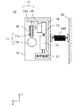
- the electromechanical device 1G includes an elastic body 18G that supports the housing 10 with respect to the upper surface 92 of a movable object (for example, a mechanical device) instead of the elastic body 18 and the attachment 19 in FIG.
- the electromechanical device 1H includes an elastic body 18H that supports the housing 10 with respect to a side surface 93 of a movable object (for example, a mechanical device) instead of the elastic body 18 and the attachment 19 in FIG.
- the elastic body that supports the housing 10 against a movable external object (movable object) is not limited to the one that suspends the housing 10, and supports the housing 10 in the upward, lateral, or other directions. You may.
- the electromechanical device 1E includes a housing 10 for accommodating a gear mechanism 12, a generator 13, a pendulum 11, a frame 14, and a first elastic body 16, and a housing.
- a second elastic body 18 that supports the body 10 with respect to an external object is further provided.
- the second elastic body 18 suspends the housing 10 from an external object and expands and contracts in the direction of gravity.
- the second elastic body 18 is equal to the natural period of the first elastic body 16, and the pendulum 11 when the load device 21 is connected to the generator 13. Has a natural period equal to the period of.
- the pendulum, the housing, and the elastic body resonate effectively, and power can be generated effectively.
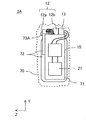
- FIG. 42 is a side view showing the configuration of the electromechanical device 3 according to the third embodiment.
- FIG. 43 is a front view showing the configuration of the electromechanical device 3 of FIG. 42.
- the electromechanical device 3 may be, for example, a wearable device worn on the user's body or clothing. Further, the electromechanical device 3 may be attached to or incorporated in an article with which the body of the user 100 temporarily comes into contact when used by the user 100.
- the electromechanical device 3 includes a gear mechanism 12, a generator 13, a power conversion circuit 15, a load device 21, a cover 70, an arm 71, an arm 72, and an elastic body 73.
- the arm 71 is connected so that the position relative to the gear mechanism 12 and the generator 13 is fixed.
- the arm 72 is connected to, that is, fitted or integrated with the input shaft 12a of the gear mechanism 12.
- the arms 71 and 72 are formed, for example, in the shape of a plate or a rod.
- the arms 71 and 72 may be composed of one member, or may be composed of a plurality of members, respectively.
- the arm 71 is also referred to as a "first arm”
- the arm 72 is also referred to as a "second arm”.
- the elastic body 73 supports the arm 72 with respect to the arm 71 so as to generate a restoring force to a predetermined position.
- the elastic body 73 is a coil spring connected between the arms 71 and 72.
- FIG. 42 shows a state in which the elastic body 73 has a natural length.
- the arm 72 has an angle of, for example, 20 to 30 degrees with respect to the arm 71.
- the elastic body 73 When the arm 72 receives an external force and rotates clockwise or counterclockwise from the position shown in FIG. 42, the elastic body 73 generates a restoring force so that the arm 72 returns to the original position.
- the elastic body 73 may be directly connected to the arm 71, or may be indirectly connected via another member.
- the cover 70 is a flexible and flexible bag-shaped member that surrounds the gear mechanism 12, the generator 13, the power conversion circuit 15, the load device 21, the arm 71, the arm 72, and the elastic body 73. By protecting the other components of the electromechanical device 3 with the cover 70, it is possible to reduce the discomfort of the user when the electromechanical device 3 is attached to the user's body, for example.
- the power conversion circuit 15 may be omitted, may be provided outside the cover 70, or may be integrated with, for example, the load device 21. In FIGS. 42 and 43, the cover 70 is shown by a broken line for the sake of explanation.
- the gear mechanism 12, the generator 13, the power conversion circuit 15, and the load device 21 are configured in the same manner as the corresponding components of the electromechanical device 1 and the like according to the first embodiment.
- the power conversion circuit 15 and the load device 21 may be provided on the arm 71, for example.
- FIG. 44 is a diagram illustrating the operation of the electromechanical device 3 of FIG. 42.
- FIG. 44A shows a state in which no external force acts on the arms 71 and 72 and the elastic body 73 has a natural length.
- FIG. 44B shows a state in which an elastic body 73 is compressed by an external force acting on the arms 71 and 72 and approaching each other.
- FIG. 44 (c) shows a state in which the arms 71 and 72 have returned to their original positions (FIG. 44 (a)) due to the restoring force of the elastic body 73.
- the arm 72 rotates around the input shaft 12a of the gear mechanism 12 according to the external force acting on the arms 71 and 72 or the restoring force of the elastic body 73, and the generator 13 generates electric power according to the rotation of the arm 72. appear.
- the electromechanical device 3 generates electric power in response to the movement of the arm 72 with respect to the arm 71 (that is, opening and closing of the arms 71 and 72), and supplies the generated electric power to the load device 21.
- FIG. 44 shows a case where the load device 21 is a wireless communication device, and when the electromechanical device 3 generates electric power, the wireless communication device communicates with the external server device 61 using the generated electric power. ..
- the electromechanical device 3 may be, for example, a wearable device worn on the user's body or clothes. Further, the electromechanical device 3 may be attached to or incorporated in an article with which the body of the user 100 temporarily comes into contact when used by the user 100. An example of using the electromechanical device 3 will be described later. Therefore, according to the electromechanical device 3, the user's daily activities and the like can be arranged in various postures as in the electromechanical devices according to the first and second embodiments, but at more opportunities than before. Therefore, it is possible to continuously and unconsciously take out a larger amount of electric power than before.
- FIG. 45 is a side view showing the configuration of the electromechanical device 3A according to the first modification of the third embodiment.
- FIG. 46 is a front view showing the configuration of the electromechanical device 3A of FIG. 45.
- the electromechanical device 3A includes an elastic body 73A which is a torsion spring instead of the elastic body 73 of FIG. 42 which is a coil spring.
- the elastic body 73A is provided around the input shaft 12a of the gear mechanism 12. One end of the elastic body 73A is connected to the arm 72, and the other end is connected to the housing 12b of the gear mechanism 12. Since the relative position of the gear mechanism 12 with respect to the arm 71 is fixed, the elastic body 73A is indirectly connected to the arm 71 by being connected to the housing 12b of the gear mechanism 12.
- the electromechanical device 3A similar to the electromechanical device 3 of FIG. 42, it can be arranged in various postures, but on more occasions than before, a larger amount of electric power is generated from the user's daily activities and the like. It can be taken out continuously and unconsciously.
- FIG. 47 is a front view showing the configuration of the electromechanical device 3B according to the second modification of the third embodiment.
- the load device 21 may be provided outside the electromechanical device 3B.
- the electromechanical device 3B supplies the electric power generated by the generator 13 to the external load device 21.
- electric power can be supplied to an arbitrary load device. Further, by separating the load device 21 from the electromechanical device 3B, the degree of freedom in arranging the load device 21 is improved.
- FIG. 48 and 49 are views showing a first usage example of the electromechanical device 3 of FIG. 42.
- the electromechanical device 3 is configured to be attachable to a joint of user 100 or to a portion of clothing corresponding to the joint of user 100.
- the generator 13 generates electric power according to the movement of the joints.
- the electromechanical device 3 is attached to the portion of the shirt 81 corresponding to the side of the user 100.
- the electromechanical device 3 may be attached to clothing using, for example, a belt, a safety pin, a hook-and-loop fastener, an adhesive tape, a clothing pocket, or the like.
- the arms 71 and 72 of the electromechanical device 3 when the user 100 moves the arm, the arms 71 and 72 of the electromechanical device 3 also open and close in accordance with the movement of the arm.
- the electromechanical device 3 generates electric power according to the opening and closing of the arms 71 and 72, and supplies the generated electric power to the load device 21.
- the opportunity to generate electric power can be increased, and as a result, the electric power generated and the amount of electric power can be increased. ..
- a large amount of electric power can be reasonably generated by utilizing the daily movements of the joints of the user 100.
- the user 100 can generate electricity unconsciously or consciously by using the electromechanical device 3.
- the user 100 can open and close the arms 71 and 72 with a small force to generate electricity unconsciously.
- the electromechanical device 3 may be attached directly to the vicinity of the joint of the user 100 by using a belt, a string, an adhesive tape, or the like instead of attaching to the clothes.
- the electromechanical device 3 may be attached in the vicinity of joints such as shoulders, elbows, wrists, hip joints, knees, and ankles, or on a portion of clothing corresponding to these joints.
- the electromechanical device 3 is configured to be attachable to the body or clothes of the user 100, not limited to joints.
- an external force acts on the arms 71 and 72.
- the generator 13 generates electric power in response to contact and separation of the user 100's body and articles.
- the electromechanical device 3 is attached to the portion of the shirt 81 corresponding to the forearm of the user 100.
- the electromechanical device 3 may be attached to clothing using, for example, a belt, a safety pin, a hook-and-loop fastener, an adhesive tape, a clothing pocket, or the like.
- the article used by the user 100 is the table 82.
- FIG. 51 (a) shows a state in which the forearm of the user 100 is separated from the table 82 and the arms 71 and 72 are open.
- FIG. 51 (b) shows a state in which the forearm of the user 100 is in contact with the table 82 and the arms 71 and 72 are closed.
- the electromechanical device 3 generates electric power according to the opening and closing of the arms 71 and 72, and supplies the generated electric power to the load device 21.
- the forearm of the user 100 since the forearm of the user 100 has many opportunities to come into contact with and separate from the table 82, the opportunity to generate electric power can be increased, and as a result, the electric power and the amount of electric power generated can be increased. Can be increased.
- the "separation" is not limited to the case where the body and the article (or at least the electromechanical device 3 and the article) of the user 100 are in a completely non-contact state, for example, between the arms 71 and 72. Indicates a state in which the angle is larger than the minimum value. At least, if the angle between the arms 71 and 72 changes, power can be generated. According to the examples of FIGS. 50 and 51, a large amount of electric power can be reasonably generated by utilizing the daily operation of the user 100. The user 100 can generate electricity unconsciously or consciously by using the electromechanical device 3. According to the lever principle, the user 100 can open and close the arms 71 and 72 with a small force to generate electricity unconsciously.
- the electromechanical device 3 may be attached directly to the body of the user 100 by using a belt, a string, an adhesive tape, or the like instead of attaching to the clothes.
- the electromechanical device 3 may be attached to a part of the user's body other than the forearm, or to a part of clothing corresponding to the part of the body.
- FIG. 52 is a diagram showing a third usage example of the electromechanical device 3 of FIG. 42.
- the electromechanical device 3 is configured to be attachable to an article with which the body of the user 100 is temporarily in contact when used by the user 100.
- an external force acts on the arms 71 and 72.
- the generator 13 generates electric power in response to contact and separation of the user 100's body and articles.
- the article with which the body of the user 100 temporarily comes into contact when used by the user 100 is the chair 83.
- the electromechanical device 3 is attached to the backrest of the chair 83.
- the electromechanical device 3 may be attached to the surface of the chair 83 by using, for example, a belt, a hook-and-loop fastener, an adhesive tape, a pocket, or the like. Further, the electromechanical device 3 may be incorporated inside the chair 83.
- FIG. 52A shows a state in which the body of the user 100 is separated from the backrest of the chair 83 and the arms 71 and 72 are open.
- FIG. 52B shows a state in which the body of the user 100 is in contact with the backrest of the chair 83 and the arms 71 and 72 are closed.
- the electromechanical device 3 generates electric power according to the opening and closing of the arms 71 and 72, and supplies the generated electric power to the load device 21.
- the opportunity to generate electric power can be increased, and as a result, the electric power generated and the amount of electric power are increased. be able to.
- FIG. 52A shows a state in which the body of the user 100 is separated from the backrest of the chair 83 and the arms 71 and 72 are open.
- FIG. 52B shows a state in which the body of the user 100 is in contact with the backrest of the chair 83 and the arms 71 and 72 are closed.
- the electromechanical device 3 generates electric power according to the opening and closing of the arms 71 and 72,
- a large amount of electric power can be reasonably generated by utilizing the daily operation of the user 100.
- the user 100 can generate electricity unconsciously or consciously by using the electromechanical device 3. According to the lever principle, the user 100 can open and close the arms 71 and 72 with a small force to generate electricity unconsciously.
- FIG. 53 is a diagram showing a fourth use example of the electromechanical device 3 of FIG. 42.
- the article with which the body of the user 100 temporarily comes into contact when used by the user 100 is the armrest 84 of the chair 83.
- the electromechanical device 3 is attached to the armrest 84.
- FIG. 54 is a diagram showing a fifth use example of the electromechanical device 3 of FIG. 42.
- the article with which the body of the user 100 temporarily comes into contact when used by the user 100 is the cushion 85.
- the electromechanical device 3 is incorporated inside the cushion 85. According to the example of FIG. 54, as in the case of the usage examples of FIGS. 52 and 53, it is possible to generate a large amount of electric power reasonably by utilizing the daily operation of the user 100.
- FIGS. 55 and 56 are views showing a sixth use example of the electromechanical device 3 of FIG. 42.
- the articles with which the body of the user 100 temporarily comes into contact when used by the user 100 are slippers 86-1 and 86-2.
- the electromechanical devices 3-1 and 3-2 are attached to the heel portions of the slippers 86-1 and 86-2, respectively.
- FIG. 56A the heel of the right foot of the user 100 is separated from the slippers 86-1, the arms 71 and 72 of the electromechanical device 3-1 are opened, and the heel of the left foot of the user 100 is in the slippers 86-2. It shows a state in which the arms 71 and 72 of the electromechanical device 3-2 are in contact with each other and are closed.
- FIG. 56B the heel of the right foot of the user 100 comes into contact with the slippers 86-1, the arms 71 and 72 of the electromechanical device 3-1 are closed, and the heel of the left foot of the user 100 comes from the slippers 86-2. It shows a state in which the arms 71 and 72 of the electromechanical device 3-2 are separated and opened.
- the electromechanical devices 3-1 and 3-2 generate electric power in response to the opening and closing of the arms 71 and 72, and supply the generated electric power to the load device 21.
- the opportunity to generate electric power can be increased, and as a result, it is generated.
- the amount of power and the amount of power can be increased.
- a large amount of electric power can be reasonably generated by utilizing the daily operation of the user 100.
- FIGS. 49 to 56 show a case where the load device 21 is a wireless communication device, and when the electromechanical device 3 generates electric power, the wireless communication device uses the generated electric power to generate an external server device 61. Communicate with.
- the electric power generated over a plurality of operations may be stored in the power storage circuit 32.
- the load device 21 includes, for example, a sensor for ecological information and a wireless communication device.
- the sensor is used to detect the user's own movement, body temperature, heartbeat, etc., and wireless communication is performed.
- the load device 21 is a lighting device, it is possible to irradiate the user 100's hand or the like by repeating the body movement of the user 100 (for example, opening / closing the side) a predetermined number of times when necessary.
- the electromechanical device 3 includes a gear mechanism 12, a generator 13, a first arm 71, a second arm 72, and an elastic body 73.
- the gear mechanism 12 has an input shaft 12a and transmits the rotation of the input shaft 12a.
- the generator 13 generates electric power according to the rotation transmitted by the gear mechanism 12.
- the first arm 71 is connected so that its position relative to the gear mechanism 12 and the generator 13 is fixed.
- the second arm 72 is connected to the input shaft 12a of the gear mechanism 12.
- the elastic body 73 supports the second arm 72 with respect to the first arm 71 so as to generate a restoring force to a predetermined position.
- the second arm 72 rotates around the input shaft 12a of the gear mechanism 12 in response to the external force acting on the arms 71 and 72 or the restoring force of the elastic body 73, and the generator 13 of the second arm 72 Generates power according to rotation.
- the elastic body 73 may be a coil spring connected between the arms 71 and 72.
- the second arm can be supported with respect to the first arm so as to generate a restoring force to a predetermined position.
- the elastic body 73 may be a torsion spring provided around the input shaft 12a of the gear mechanism 12.
- the second arm can be supported with respect to the first arm so as to generate a restoring force to a predetermined position.
- the load device 21 that operates by the electric power generated by the generator 13 may be further provided.
- the convenience can be improved by integrating the load device with the electromechanical device.
- the electric power generated by the generator 13 may be supplied to the external load device 21.
- the electric power generated by the generator 13 may be supplied to the load device 21 in real time.
- a power storage circuit 32 for storing the electric power generated by the generator 13 may be further provided.
- the amount of electricity stored in the electricity storage circuit 32 reaches a predetermined threshold value representing an amount sufficient to operate the load device 21, the electric power stored in the electricity storage circuit 32 is supplied to the load device 21.
- the load device 21 may include any one of a lighting device, a rechargeable battery, a motor, a sensor, and a wireless communication device.
- any load device can be operated according to the user's needs.
- the electromechanical device 3 may be configured to be attached to the joint of the user 100 or to a portion of clothing corresponding to the joint of the user 100. ..
- the generator 13 generates electric power according to the movement of the joints.
- the electromechanical device 3 may be configured to be attached to the body or clothes of the user 100.
- an external force acts on the arms 71 and 72.
- the generator 13 generates electric power in response to contact and separation of the user 100's body and articles.
- the electromechanical device 3 may be configured to be attached to an article with which the body of the user 100 temporarily comes into contact when used by the user 100.
- an external force acts on the arms 71 and 72.
- the generator 13 generates electric power in response to contact and separation of the user 100's body and articles.
- the elastic body is not limited to the coil spring and the torsion spring, and any member that elastically expands and contracts or rotates, such as a strap-shaped member such as rubber or plastic, can be used.
- the electromechanical device reciprocates the pendulum around two or three axes that are orthogonal or intersecting each other within at least a predetermined angular range so that one generator generates electricity in response to the reciprocation of the pendulum. It may be configured.
- the electromechanical device may also include two or three generators, each with rotating shafts arranged along two or three axes that are orthogonal or intersecting each other.
- the output power of the plurality of generators may be stored in a common power storage circuit or may be stored in different power storage circuits.
- the amount of power generated can be increased by efficiently utilizing the two-dimensional or three-dimensional inertial force, centrifugal force, gravity, and other acting forces that are spatially generated by the movement of the moving object.
- a reciprocating linear generator may be, for example, a linear motor.
- the electromechanical device is provided with an arbitrary reciprocating motion mechanism that drives the reciprocating linear generator in response to the overall vibration of the electromechanical device instead of the pendulum.
- the reciprocating linear generator generates positive and negative voltages at the output terminals according to the operation of the reciprocating motion mechanism.
- the gear mechanism 12 may be omitted, or the gear mechanism 12 is configured to transmit the rotation of the input shaft 12a to the generator 13 at a predetermined reduction ratio. You may. Further, the input shaft 12a of the gear mechanism 12 and the rotation shaft of the generator 13 may or may not be coaxial. Further, the spur gear train and the flat generator may be arranged in parallel.
- the rectifier circuit 31 and the power storage circuit 32 may perform voltage doubler rectification.
- the rectifier circuit 31 may perform half-wave rectification, full-wave rectification, or other rectification.
- the frame may be integrated with the housing of the electromechanical device. As a result, the number of parts of the electromechanical device can be reduced and the configuration of the electromechanical device can be simplified.
- Each component of the electromechanical device may be composed of various materials and may have various operating principles. These materials and operating principles can be arbitrarily combined depending on the application of the electromechanical device and the load device.
- an electromechanical device that is attached to a movable object and converts the motion or mechanical energy of the motion into electrical energy. According to the present disclosure, there is provided an electromechanical device capable of continuously and unconsciously extracting a relatively large amount of electric power from a user's daily activities.
- the present disclosure it is also possible to determine the time, time length, and type of acceleration and deceleration movements of a moving object, so that the behavior of a human, animal, or other object to which an electromechanical device is attached can be determined. It can also be detected.
- Electromechanical device 10 Housing 11 Pendulum 12 Gear mechanism 12a Input shaft 12b Housing 13 Generator 14 Frame 15 Power conversion circuit 16, 16Aa, 16Ab, 16B Elastic body 17 Fixture 18 , 18F-18H Elastic body 19 Fixture 21 Load device 22 Battery 23 Fan 31 Rectifier circuit 32 Power storage circuit 33 Control circuit 41 Belt 42 Bag 43 Trunk 45 Strap 46 Pocket 47 Shoes 48 Hat 49 Glasses 50 Helmet 51 Umbrella 52 Cane 53 Knapsack 61 Server device 70 Cover 71 First arm 72 Second arm 73, 73A Elastic body 81 Shirt 82 Table 83 Chair 84 Armrest 85 Cushion 86-1,86-2 Slippers 100 User 110 Animal 120 Washing machine 130 Bicycle 140 Tree
Landscapes
- Engineering & Computer Science (AREA)
- Power Engineering (AREA)
- Connection Of Motors, Electrical Generators, Mechanical Devices, And The Like (AREA)
Priority Applications (4)
| Application Number | Priority Date | Filing Date | Title |
|---|---|---|---|
| EP21776650.0A EP4131740A1 (en) | 2020-03-27 | 2021-03-17 | Electromechanical device |
| US17/913,814 US20240213850A1 (en) | 2020-03-27 | 2021-03-17 | Electromechanical apparatus capable of continuously and unconsciously extracting electric power from daily activities |
| CN202180024496.4A CN115413393A (zh) | 2020-03-27 | 2021-03-17 | 电力机械装置 |
| JP2022509999A JPWO2021193272A1 (https=) | 2020-03-27 | 2021-03-17 |
Applications Claiming Priority (2)
| Application Number | Priority Date | Filing Date | Title |
|---|---|---|---|
| JP2020058384 | 2020-03-27 | ||
| JP2020-058384 | 2020-03-27 |
Publications (1)
| Publication Number | Publication Date |
|---|---|
| WO2021193272A1 true WO2021193272A1 (ja) | 2021-09-30 |
Family
ID=77890317
Family Applications (1)
| Application Number | Title | Priority Date | Filing Date |
|---|---|---|---|
| PCT/JP2021/010752 Ceased WO2021193272A1 (ja) | 2020-03-27 | 2021-03-17 | 電気機械装置 |
Country Status (5)
| Country | Link |
|---|---|
| US (1) | US20240213850A1 (https=) |
| EP (1) | EP4131740A1 (https=) |
| JP (1) | JPWO2021193272A1 (https=) |
| CN (1) | CN115413393A (https=) |
| WO (1) | WO2021193272A1 (https=) |
Cited By (1)
| Publication number | Priority date | Publication date | Assignee | Title |
|---|---|---|---|---|
| JP2023136682A (ja) * | 2022-03-17 | 2023-09-29 | 国立大学法人 長崎大学 | 発電装置及び発電装置の装着方法 |
Citations (10)
| Publication number | Priority date | Publication date | Assignee | Title |
|---|---|---|---|---|
| JP2003169423A (ja) * | 2001-11-30 | 2003-06-13 | Norihiro Baba | 携帯電話用充電器 |
| JP2003333795A (ja) * | 2002-05-13 | 2003-11-21 | Nidec Copal Corp | 携帯充電器 |
| JP2004052747A (ja) * | 2002-05-18 | 2004-02-19 | Kozo Oshio | 運動量変換バンド |
| JP2006009573A (ja) * | 2004-05-07 | 2006-01-12 | Ebina Koji | 発電機等の電力発生用動力源の構造 |
| JP2009536709A (ja) * | 2006-05-05 | 2009-10-15 | エスアールアイ インターナショナル | 電気活性高分子を使用した波力発電 |
| JP2011176996A (ja) * | 2010-01-29 | 2011-09-08 | Imasen Electric Ind Co Ltd | 振動発電装置 |
| JP5166193B2 (ja) | 2008-06-06 | 2013-03-21 | 裕 吉武 | 携帯端末装置及び端末保持装置 |
| CN105649864A (zh) * | 2014-09-24 | 2016-06-08 | 无锡津天阳激光电子有限公司 | 一种海龟外形双摆板双振子式海浪发电机 |
| US20180017125A1 (en) * | 2016-07-14 | 2018-01-18 | Siemens Aktiengesellschaft | Oscillation absorber for a structure |
| JP2018031322A (ja) * | 2016-08-25 | 2018-03-01 | 浩平 速水 | 発電システム |
Family Cites Families (39)
| Publication number | Priority date | Publication date | Assignee | Title |
|---|---|---|---|---|
| US4438343A (en) * | 1982-11-12 | 1984-03-20 | Marken John P | Wave power generator |
| JP3757826B2 (ja) * | 2000-07-05 | 2006-03-22 | セイコーエプソン株式会社 | カード型発電機及びそれを用いた電子機器 |
| AU2002340926A1 (en) * | 2001-05-09 | 2002-11-18 | Harmonic Drive, Inc. | Linear magnetic harmonic motion converter |
| WO2005008805A2 (en) * | 2003-05-08 | 2005-01-27 | Power Estimate Company | Apparatus and method for generating electrical energy from motion |
| US20070137943A1 (en) * | 2003-09-05 | 2007-06-21 | Paul Duclos | Pendulum actuated gearing mechanism and power generation system using same |
| CN2672944Y (zh) * | 2003-12-22 | 2005-01-19 | 重庆永旺科技发展有限公司 | 摇臂发电装置 |
| US20060049001A1 (en) * | 2004-09-09 | 2006-03-09 | Mark Streitman | Driven pendulum apparatus and method of operation thereof |
| WO2006043600A1 (ja) * | 2004-10-19 | 2006-04-27 | Kyoto University | エネルギ変換器、旗型エネルギ変換装置 |
| WO2007038157A2 (en) * | 2005-09-23 | 2007-04-05 | Regents Of The University Of California | Energy harvesting using frequency rectification |
| GB2431055B (en) * | 2005-10-04 | 2009-01-28 | Perpetuum Ltd | An electromechanical generator for converting mechanical vibrational energy into electrical energy |
| CA2649198A1 (en) * | 2006-07-19 | 2008-01-24 | Paul Duclos | Pendulum mechanism and power generation system using same |
| US20120139262A1 (en) * | 2006-10-05 | 2012-06-07 | Marshall University Research Corporation | Motion induced electric generator |
| US7629700B2 (en) * | 2006-10-05 | 2009-12-08 | Marshall University Research Corp. | Motion induced electrical generator for charging and operating devices |
| US7847421B2 (en) * | 2007-01-19 | 2010-12-07 | Willowview Systems, Inc. | System for generating electrical energy from ambient motion |
| WO2008121954A1 (en) * | 2007-03-29 | 2008-10-09 | Lighting Packs Llc | Backpack based system for human electricity generation and use when off the electric grid |
| US8134281B2 (en) * | 2007-07-10 | 2012-03-13 | Omnitek Partners Llc | Electrical generators for use in unmoored buoys and the like platforms with low-frequency and time-varying oscillatory motions |
| JP5193545B2 (ja) * | 2007-09-27 | 2013-05-08 | 三洋電機株式会社 | 発電装置および電子機器 |
| US20090200983A1 (en) * | 2008-02-07 | 2009-08-13 | David Dyer | Self-powering on-board power generation |
| US8410667B2 (en) * | 2008-06-19 | 2013-04-02 | Omnitek Partners Llc | Electrical generators for low-frequency and time-varying rocking and rotary motions |
| US7821183B2 (en) * | 2008-06-19 | 2010-10-26 | Omnitek Partners Llc | Electrical generators for low-frequency and time-varying rocking and rotary motion |
| DE102008029374A1 (de) * | 2008-06-20 | 2010-01-07 | Siemens Aktiengesellschaft | Vorrichtung zur Erzeugung elektrischer Energie aus mechanischen Vibrationen verschiedenster Amplituden und Frequenzen mittels Piezoaktoren |
| US8030786B2 (en) * | 2008-08-22 | 2011-10-04 | Willowview Systems, Inc. | System for generating electrical energy from ambient energy |
| TWI438337B (zh) * | 2008-10-08 | 2014-05-21 | Ind Tech Res Inst | 擺動裝置及其獵能裝置 |
| US8026620B2 (en) * | 2008-11-14 | 2011-09-27 | Hobdy Miles | Wave energy converter |
| US8836152B2 (en) * | 2008-11-14 | 2014-09-16 | Miles HOBDY | Hydraulic wave energy converter with variable damping |
| US8476778B2 (en) * | 2009-03-09 | 2013-07-02 | Miw Associates, Llc | Energy generator |
| EP2360535B1 (fr) * | 2010-02-24 | 2012-12-05 | Blancpain S.A. | Masse oscillante pour montre à remontage automatique, comportant un dispositif indicateur de la réserve de marche intégré dans ladite masse oscillante |
| AT509918B1 (de) * | 2010-06-07 | 2013-09-15 | Eichhorn Karl | Vorrichtung zur umwandlung von kinetischer energie in elektrische energie |
| US8299659B1 (en) * | 2010-08-14 | 2012-10-30 | Bartol Jr Robert J | Electric power generator apparatus |
| NL2007609C2 (en) * | 2011-10-18 | 2013-04-22 | Univ Delft Tech | Energy harvester. |
| GB201207987D0 (en) * | 2012-05-04 | 2012-06-20 | Imp Innovations Ltd | Power generation device |
| WO2013175449A2 (en) * | 2012-05-25 | 2013-11-28 | Yu Jia | Energy-Harvesting Apparatus and Method |
| US8866316B2 (en) * | 2012-06-21 | 2014-10-21 | General Electric Company | Tunable vibration energy harvester and method |
| CN103036478A (zh) * | 2013-01-11 | 2013-04-10 | 浙江工商大学 | 带有弹性放大机构的高效宽频带振动能量采集器 |
| US9121394B2 (en) * | 2013-04-04 | 2015-09-01 | Metso Minerals Industries, Inc. | Energy harvester for converting vibrational motion of a vibrating equipment into electrical energy, and a device for monitoring the operation of a vibrating equipment |
| KR101504867B1 (ko) * | 2014-03-27 | 2015-03-23 | 중앙대학교 산학협력단 | 능동형 에너지 수확기 |
| JP2016178821A (ja) * | 2015-03-20 | 2016-10-06 | 株式会社東芝 | 振動発電機 |
| WO2021092404A1 (en) * | 2019-11-06 | 2021-05-14 | Positive Energy, a Gravity and Motion Company, Inc. | Methods and apparatus for kinetic energy harvesting |
| US11437886B2 (en) * | 2019-11-06 | 2022-09-06 | Positive Energy, a Gravity and Motion Company, Inc. | Methods and apparatus for kinetic energy harvesting |
-
2021
- 2021-03-17 WO PCT/JP2021/010752 patent/WO2021193272A1/ja not_active Ceased
- 2021-03-17 JP JP2022509999A patent/JPWO2021193272A1/ja active Pending
- 2021-03-17 EP EP21776650.0A patent/EP4131740A1/en not_active Withdrawn
- 2021-03-17 CN CN202180024496.4A patent/CN115413393A/zh active Pending
- 2021-03-17 US US17/913,814 patent/US20240213850A1/en not_active Abandoned
Patent Citations (10)
| Publication number | Priority date | Publication date | Assignee | Title |
|---|---|---|---|---|
| JP2003169423A (ja) * | 2001-11-30 | 2003-06-13 | Norihiro Baba | 携帯電話用充電器 |
| JP2003333795A (ja) * | 2002-05-13 | 2003-11-21 | Nidec Copal Corp | 携帯充電器 |
| JP2004052747A (ja) * | 2002-05-18 | 2004-02-19 | Kozo Oshio | 運動量変換バンド |
| JP2006009573A (ja) * | 2004-05-07 | 2006-01-12 | Ebina Koji | 発電機等の電力発生用動力源の構造 |
| JP2009536709A (ja) * | 2006-05-05 | 2009-10-15 | エスアールアイ インターナショナル | 電気活性高分子を使用した波力発電 |
| JP5166193B2 (ja) | 2008-06-06 | 2013-03-21 | 裕 吉武 | 携帯端末装置及び端末保持装置 |
| JP2011176996A (ja) * | 2010-01-29 | 2011-09-08 | Imasen Electric Ind Co Ltd | 振動発電装置 |
| CN105649864A (zh) * | 2014-09-24 | 2016-06-08 | 无锡津天阳激光电子有限公司 | 一种海龟外形双摆板双振子式海浪发电机 |
| US20180017125A1 (en) * | 2016-07-14 | 2018-01-18 | Siemens Aktiengesellschaft | Oscillation absorber for a structure |
| JP2018031322A (ja) * | 2016-08-25 | 2018-03-01 | 浩平 速水 | 発電システム |
Cited By (2)
| Publication number | Priority date | Publication date | Assignee | Title |
|---|---|---|---|---|
| JP2023136682A (ja) * | 2022-03-17 | 2023-09-29 | 国立大学法人 長崎大学 | 発電装置及び発電装置の装着方法 |
| JP7813457B2 (ja) | 2022-03-17 | 2026-02-13 | 国立大学法人 長崎大学 | 発電装置及び発電装置の装着方法 |
Also Published As
| Publication number | Publication date |
|---|---|
| EP4131740A1 (en) | 2023-02-08 |
| JPWO2021193272A1 (https=) | 2021-09-30 |
| US20240213850A1 (en) | 2024-06-27 |
| CN115413393A (zh) | 2022-11-29 |
Similar Documents
| Publication | Publication Date | Title |
|---|---|---|
| US9362803B2 (en) | Human powered generator | |
| EP1610646B1 (en) | A backpack for harvesting electrical energy during walking and for minimizing shoulder strain | |
| US7851932B2 (en) | Backpack based system for human electricity generation and use when off the electric grid | |
| Wu et al. | Generating electricity during locomotion modes dominated by negative work via a knee energy-harvesting exoskeleton | |
| Teng et al. | Prolonging VR haptic experiences by harvesting kinetic energy from the user | |
| Xie et al. | Increased energy harvesting from backpack to serve as self-sustainable power source via a tube-like harvester | |
| US11476780B2 (en) | Energy harvester and a wearable device | |
| Chan et al. | Knee energy harvester with variable transmission to reduce the effect on the walking gait | |
| CN113681545A (zh) | 膝关节负功捕捉外骨骼装置 | |
| Dhand et al. | A brief review on human-powered lower-limb exoskeletons | |
| WO2021193272A1 (ja) | 電気機械装置 | |
| Liu et al. | Energy harvesting from ankle: generating electricity by harvesting negative work | |
| Singla et al. | Toward human-powered lower limb exoskeletons: A review | |
| Purwadi et al. | Development of biomechanical energy harvesting device using heel strike | |
| JP7157962B2 (ja) | 電気機械装置 | |
| US12152568B2 (en) | Biomechanical electric generator | |
| Donelan et al. | Biomechanical energy harvesting | |
| Shahhaidar et al. | Electromagnetic generator: As respiratory effort energy harvester | |
| Chan et al. | A smart wearable device for capturing biomechanical energy from human knee motion | |
| Venugopal et al. | An efficient hybrid biomechanical energy harvesting system using human motions for low-power applications | |
| George et al. | Arm Motion Dynamics to Excite a Mobile Energy Harvesting Autowinder | |
| CN215733619U (zh) | 一种高灵敏野外可穿戴的自供电装置 | |
| Carroll | Miniaturised Electromagnetic Generators for Portable Applications | |
| Endo et al. | Modular design of emotion expression humanoid robot kobian | |
| George | Human Powered Energy Harvester based on Autowinder Mechanism: Analysis, Build and Test |
Legal Events
| Date | Code | Title | Description |
|---|---|---|---|
| 121 | Ep: the epo has been informed by wipo that ep was designated in this application |
Ref document number: 21776650 Country of ref document: EP Kind code of ref document: A1 |
|
| ENP | Entry into the national phase |
Ref document number: 2022509999 Country of ref document: JP Kind code of ref document: A |
|
| WWE | Wipo information: entry into national phase |
Ref document number: 17913814 Country of ref document: US |
|
| WWE | Wipo information: entry into national phase |
Ref document number: 2021776650 Country of ref document: EP |
|
| ENP | Entry into the national phase |
Ref document number: 2021776650 Country of ref document: EP Effective date: 20221027 |
|
| NENP | Non-entry into the national phase |
Ref country code: DE |