WO2021192908A1 - 追跡方法 - Google Patents
追跡方法 Download PDFInfo
- Publication number
- WO2021192908A1 WO2021192908A1 PCT/JP2021/008569 JP2021008569W WO2021192908A1 WO 2021192908 A1 WO2021192908 A1 WO 2021192908A1 JP 2021008569 W JP2021008569 W JP 2021008569W WO 2021192908 A1 WO2021192908 A1 WO 2021192908A1
- Authority
- WO
- WIPO (PCT)
- Prior art keywords
- unit
- person
- image data
- tracking
- information
- Prior art date
Links
Images


Classifications
-
- G—PHYSICS
- G06—COMPUTING; CALCULATING OR COUNTING
- G06T—IMAGE DATA PROCESSING OR GENERATION, IN GENERAL
- G06T7/00—Image analysis
-
- G—PHYSICS
- G06—COMPUTING; CALCULATING OR COUNTING
- G06T—IMAGE DATA PROCESSING OR GENERATION, IN GENERAL
- G06T7/00—Image analysis
- G06T7/20—Analysis of motion
- G06T7/246—Analysis of motion using feature-based methods, e.g. the tracking of corners or segments
Definitions
- the present invention relates to a tracking method, a tracking device, and a recording medium.
- Patent Document 1 is a document that describes walking analysis of a person.
- Patent Document 1 is created by a data acquisition unit that acquires two types of image data from a depth sensor, a skeleton information creation unit that creates skeleton information based on the image data acquired by the data acquisition unit, and a skeleton information creation unit.
- a gait analyzer having a correction processing unit that corrects skeleton information and an analysis processing unit that analyzes the user's gait using the corrected skeleton information is described.
- Patent Document 1 it is essential to use a depth sensor (3D sensor), but it is desired to perform gait analysis based on image data acquired by a camera without using a 3D sensor such as a depth sensor. There is a need.
- 3D sensor 3D sensor
- an object of the present invention is to provide a tracking method, a tracking device, and a recording medium that solve the problem that it may be difficult to track the same person between image data.
- the tracking method which is a form of the present disclosure to achieve such an object,
- Information processing device By recognizing the skeleton of a person in the image data, information indicating multiple parts of the recognized person is acquired, and information is obtained. Based on the acquired information, the same person is tracked among a plurality of image data.
- the tracking device which is another form of the present disclosure, An acquisition unit that acquires information indicating multiple parts of the recognized person by recognizing the skeleton of the person in the image data, and an acquisition unit. A tracking unit that tracks the same person among a plurality of image data based on the information acquired by the acquisition unit. It has a structure of having.
- the recording medium which is another form of the present disclosure is In the tracking device, An acquisition unit that acquires information indicating multiple parts of the recognized person by recognizing the skeleton of the person in the image data, and an acquisition unit. A tracking unit that tracks the same person among a plurality of image data based on the information acquired by the acquisition unit. It is a computer-readable recording medium on which a program for realizing the above is recorded.
- FIG. 1st Embodiment of this disclosure It is a figure which shows the structural example of the walking posture measurement system in 1st Embodiment of this disclosure. It is a figure which shows an example at the time of photographing the walking posture in the front-back direction. It is a figure which shows an example at the time of photographing the walking posture in the left-right direction. It is a block diagram which shows the configuration example of the smartphone shown in FIG. It is a block diagram which shows the structural example of the photographing auxiliary part shown in FIG. It is a figure which shows the example of the shooting assistance display at the time of holding horizontally. It is a figure which shows the example of the shooting assistance display at the time of holding vertically. It is a figure which shows the operation example of the angle adjustment information output part shown in FIG.
- FIG. 1 It is a block diagram which shows the structural example of the walking posture measuring apparatus shown in FIG. It is a figure which shows an example of the skeleton information shown in FIG. It is a figure which shows an example of the measurement result information shown in FIG. It is a figure for demonstrating the processing of the measured value calculation part. It is a figure for demonstrating the processing of the measured value calculation part. It is a figure for demonstrating the processing of the measured value calculation part. It is a figure for demonstrating the processing of the measured value calculation part. It is a figure for demonstrating the processing of the measured value calculation part. It is a figure for demonstrating the processing of the measured value calculation part. It is a figure for demonstrating the processing of the measured value calculation part. It is a figure for demonstrating the processing of the measured value calculation part. It is a figure for demonstrating the processing of the measured value calculation part. It is a figure for demonstrating the processing of the measured value calculation part. It is a figure for demonstrating the processing of the measured value calculation part.
- FIG. 1 It is a figure which shows an example of the figure generated by the inclusion figure generation part shown in FIG. It is a flowchart which shows the operation example of the tracking part. It is a figure which shows an example of the hardware composition which the photographing apparatus has in 3rd Embodiment of this disclosure. It is a block diagram which shows the structural example of the photographing apparatus. It is a block diagram which shows the structural example of the information processing apparatus in 4th Embodiment of this disclosure. It is a block diagram which shows the structural example of the information processing apparatus in 5th Embodiment of this disclosure. It is a block diagram which shows the structural example of the tracking apparatus in 6th Embodiment of this disclosure.
- FIG. 1 is a diagram showing a configuration example of the walking posture measurement system 100.
- FIG. 2 is a diagram showing an example of photographing a walking posture in the front-back direction.
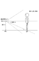
- FIG. 3 is a diagram showing an example of photographing a walking posture in the left-right direction.
- FIG. 4 is a block diagram showing a configuration example of the smartphone 200.
- FIG. 5 is a block diagram showing a configuration example of the photographing auxiliary unit 212.
- FIG. 6 is a diagram showing an example of a shooting assistance display when the camera is held horizontally.
- FIG. 7 is a diagram showing an example of a shooting auxiliary display when the camera is held vertically.
- FIG. 1 is a diagram showing a configuration example of the walking posture measurement system 100.
- FIG. 2 is a diagram showing an example of photographing a walking posture in the front-back direction.
- FIG. 3 is a diagram showing an example of photographing a walking posture in the left-right direction.
- FIG. 4 is a block diagram
- FIG. 8 is a diagram showing an operation example of the angle adjustment information output unit 2124.
- FIG. 9 is a block diagram showing a configuration example of the walking posture measuring device 300.
- FIG. 10 is a diagram showing an example of skeleton information 334.
- FIG. 11 is a diagram showing an example of measurement result information 336.
- FIG. 12 is a diagram for explaining the processing of the actually measured value calculation unit 343.
- 13 to 19 are diagrams for explaining the processing of the actually measured value calculation unit 343.
- FIG. 20 is a flowchart showing an operation example of the photographing assisting unit 212 in the smartphone 200.
- FIG. 21 is a flowchart showing an operation example of the walking posture measuring device 300.
- FIG. 22 is a flowchart showing an example of processing for calculating the measured value information 335.
- the walking posture measuring system 100 that measures the walking posture of a person based on a moving image acquired by using a photographing device such as a smartphone 200 will be described.
- a moving image showing a person walking in the front-back direction of an image that is, a plurality of image data
- a moving image showing a person walking in the left-right direction of the image and a moving image showing a person walking in the left-right direction of the image, using a smartphone 200
- the walking posture measuring system 100 measures the walking posture such as stride length, walking speed, straightness according to blurring of the head during walking, etc., based on a plurality of image data which are moving images acquired by shooting.
- the walking posture measurement system 100 includes a mechanism for aligning shooting conditions as much as possible when acquiring image data using the smartphone 200, a mechanism for measuring an actually measured value from the image data, and the like. I'm out.
- FIG. 1 shows a configuration example of the walking posture measurement system 100.
- the walking posture measuring system 100 includes, for example, a smartphone 200 and a walking posture measuring device 300.
- the smartphone 200 and the walking posture measuring device 300 are connected so as to be able to communicate with each other by, for example, wirelessly or by wire.
- the smartphone 200 functions as a photographing device for photographing a person walking.
- the smartphone 200 may be a smartphone having general functions such as a camera function, a touch panel 201 for displaying a screen, and various sensors such as a GPS sensor and an acceleration sensor.
- the photographer takes a picture of a person walking from the back of the screen to the front, etc., while holding the smartphone 200 vertically (holding it vertically).
- the photographer takes a picture of a person walking in the front-back direction while the short side of the rectangular-shaped smartphone 200 is held vertically so as to be horizontal to the ground.
- the photographer takes a picture of a person walking in the left-right direction such as from the left to the right of the screen while the smartphone 200 is held sideways (sideways).
- the photographer takes a picture of a person walking in the front-back direction while the smartphone 200 is held sideways with the long side horizontal to the ground.
- the photographer shoots a type of moving image (a plurality of image data) according to the orientation of the smartphone 200.
- the appearance of a person walking in the front-back direction and the appearance of a person walking in the left-right direction may be divided into two shots using, for example, one smartphone 200, or two smartphones 200 may be used. You may shoot at the same time.
- FIG. 4 shows a characteristic configuration example in the present embodiment of the smartphone 200.
- the smartphone 200 has a measurement motion photographing unit 210 in addition to a general configuration as a smartphone such as an acceleration sensor and a gyro sensor for detecting the orientation (vertical orientation, horizontal orientation) of the smartphone 200. doing.
- the measurement motion photographing unit 210 includes an image data photographing unit 211 and an imaging assisting unit 212.
- the smartphone 200 has an arithmetic unit such as a CPU (Central Processing Unit) and a storage device.
- the smartphone 200 realizes the above-mentioned processing unit by, for example, executing a program stored in the storage device by the arithmetic unit.
- the measurement motion photographing unit 210 photographs a person walking, which is the measurement motion in the present embodiment, in response to the photographer's operation on the smartphone 200.
- the measurement motion photographing unit 210 includes a function for assisting shooting so that shooting can be performed under the same conditions as possible when performing shooting.
- the measurement motion photographing unit 210 has a camera operation function for photographing a person walking, and also captures the walking direction, angle, size reflected on the screen, etc. when photographing the person walking. It is a shooting application that has a guide function to meet the conditions as much as possible.
- the measurement motion photographing unit 210 includes an image data photographing unit 211 and an imaging assisting unit 212.
- the image data shooting unit 211 acquires a moving image (a plurality of image data) by shooting a person using the camera of the smartphone 200. Further, the image data shooting unit 211 associates the moving image (image data) shot by the image data shooting unit 211 with information indicating the acquisition date and time of the image data, information acquired by the shooting assistance unit 212, which will be described later, and the like. Can be done.
- the shooting assistance unit 212 assists the image data shooting unit 211 to arrange the shooting conditions as much as possible when acquiring the image data.
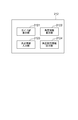
- FIG. 5 shows an example of the configuration included in the photographing assisting unit 212.
- the photographing auxiliary unit 212 includes, for example, a guide line display unit 2121, an angle information display unit 2122, a height information input unit 2123, and an angle adjustment information output unit 2124.
- the guide line display unit 2121 displays the guide line 2011 on the touch panel 201, which serves as a guideline for the position where the person walks, such as the position of the person's feet when shooting the person.
- the guide line 2011 displayed on the touch panel 201 as much as possible, it is possible to align the walking direction, angle, size displayed on the screen, etc. when the person walks. ..
- a mark or the like may be placed in the real world so that the position coincides with the position indicated by the guide line 2011, and the person may walk using the mark.
- the guide line display unit 2121 displays different guide lines 2011 on the touch panel 201 depending on whether the smartphone 200 is held vertically or horizontally. For example, when it is determined that the smartphone 200 is held horizontally based on the information acquired from the acceleration sensor or the like, the guide line display unit 2121 is for photographing a person walking in the left-right direction of the screen as shown in FIG.
- the guide line 2011 is displayed on the touch panel 201.
- the guide line display unit 2121 displays a guide line 2011 for guiding a person walking in the left-right direction on the touch panel 201.
- the shooting area which is the area shot by the camera of the smartphone 200
- the guide line 2011 is displayed.
- the guide line display unit 2121 photographs a person walking in the front-back direction of the screen as shown in FIG.
- the guide line 2011 for this purpose is displayed on the touch panel 201.
- the guide line display unit 2121 displays a guide line 2011 for guiding a person walking in the front-back direction on the touch panel 201.
- the position where the guide line display unit 2121 displays the guide line 2011 is, for example, predetermined.
- the guide line display unit 2121 displays the guide line 2011 below the center of the photographing area (for example, about the middle of the lower half area) as shown in FIG.
- the guide line display unit 2121 displays the guide line 2011 in the center of the photographing area as shown in FIG. 7.
- the position where the guide line display unit 2121 displays the guide line 2011 may be other than those illustrated above.
- the angle information display unit 2122 acquires information indicating the angle of the smartphone 200, such as an inclination in the left-right direction and an inclination in the front-back direction, from an acceleration sensor or a gyro sensor of the smartphone 200. Then, the angle information display unit 2122 displays the acquired information on the touch panel 201 as angle information 2012 indicating the angle of the smartphone 200.
- angle information 2012 When shooting a person walking, it is desirable that the smartphone 200 is not tilted as much as possible.
- By displaying the angle information 2012 on the touch panel 201 by the angle information display unit 2122 it is possible to correct the angle of the smartphone 200 when the photographer takes a picture of a person walking, and it is desirable that the smartphone 200 is not tilted. It is possible to take a picture of a person walking in a state.
- the angle information display unit 2122 displays information indicating the inclination in the left-right direction and information indicating the inclination in the front-back direction on the touch panel 201.
- the angle information display unit 2122 displays information indicating the inclination of the smartphone 200 in the horizontal direction and the vertical direction.
- the angle information display unit 2122 displays the angle information 2012 at a predetermined position on the touch panel 201.
- the display of the angle information 2012 by the angle information display unit 2122 is the same (display according to the inclination) although the display position changes depending on whether the smartphone 200 is held vertically or horizontally. It doesn't matter.
- the height information input unit 2123 receives input of height information indicating the height h from the ground of the smartphone 200 from a person, and displays the height display unit 2013 displaying the input height h on the touch panel 201 on the touch panel 201. do.
- the height h received by the height information input unit 2123 can be utilized when the walking posture measuring device 300 calculates the actually measured value W.
- the height information input unit 2123 displays the height display unit 2013 at a predetermined position on the touch panel 201. Then, the height information input unit 2123 receives, for example, an input of information indicating the height h from the person by touching the height display unit 2013 by a person who operates the smartphone 200. After that, the height information input unit 2123 displays the information indicating the received height h on the height display unit 2013.
- the display of the height display unit 2013 by the height information input unit 2123 may be the same as the display content although the display position changes depending on whether the smartphone 200 is held vertically or horizontally.
- the angle adjustment information output unit 2124 outputs information for adjusting the inclination of the smartphone 200.
- the angle adjustment information output unit 2124 outputs information according to the inclination of the smartphone 200, which differs depending on the inclination of the smartphone 200.
- the angle adjustment information output unit 2124 outputs a sound adjusted according to the inclination of the smartphone 200 as information for adjusting the inclination of the smartphone 200.
- FIG. 8 shows an example of processing by the angle adjustment information output unit 2124.
- the angle adjustment information output unit 2124 outputs a sound whose length is adjusted according to the inclination of the smartphone 200 in the left-right direction, and outputs the sound whose length is adjusted according to the inclination of the smartphone 200 in the front-back direction. Outputs a sound with adjusted pitch.
- the angle adjustment information output unit 2124 makes different adjustments depending on how the smartphone 200 is tilted. For example, referring to FIG. 8, the angle adjustment information output unit 2124 adjusts the length of one sound so that the more the smartphone 200 is tilted to the left, the shorter the length of one sound is.
- the angle adjustment information output unit 2124 adjusts the length of the sound so that the longer the smartphone 200 is tilted to the right, the longer the length of one sound is. Further, the angle adjustment information output unit 2124 adjusts the pitch so that the pitch is lowered as the smartphone 200 is tilted toward the front (for example, the photographer side). Further, the angle adjustment information output unit 2124 adjusts the pitch so that the pitch increases as the smartphone 200 tilts toward the back (for example, the side opposite to the photographer).
- the angle adjustment information output unit 2124 adjusts at least one of the length and pitch of the sound according to the tilt. Outputs two types of sounds.
- the smartphone 200 is not tilted, the length and pitch of the sound are not adjusted, so that the angle adjustment information output unit 2124 outputs one type of sound.
- the information for adjusting the tilt of the smartphone 200 which is output by the angle adjustment information output unit 2124, is not necessarily limited to the case of sound.
- the angle adjustment information output unit 2124 may illuminate a light or vibrate the smartphone 200 instead of the sound.
- the angle adjustment information output unit 2124 may be configured to perform processing such as illuminating a light or vibrating the smartphone 200 when approaching an angle having no inclination, which is a correct angle.
- the angle adjustment information output unit 2124 outputs a sound according to the inclination in the left-right direction and illuminates the light according to the inclination in the front-back direction, and outputs a sound and illuminates the light according to the inclination in the left-right direction.
- the above-mentioned processes may be combined in various combinations such as.
- the above is a configuration example of the smartphone 200, which is characteristic of this embodiment.
- the walking posture measuring device 300 is a server device that measures the walking posture such as stride length, walking speed, straightness, etc., based on a moving image (that is, a plurality of image data) taken by the smartphone 200.
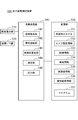
- FIG. 9 shows a configuration example of the walking posture measuring device 300.
- the walking posture measuring device 300 has, for example, a screen display unit 310, a communication I / F unit 320, a storage unit 330, and an arithmetic processing unit 340 as main components. There is.
- the screen display unit 310 includes a screen display device such as a touch panel or a liquid crystal display.
- the screen display unit 310 displays the position of the skeleton indicated by the skeleton information 334 in the image data included in the image information 333, the skeleton information 334, the measurement result information 336, and the image information 333 in response to an instruction from the arithmetic processing unit 340. It is possible to display superimposed images, etc.
- the communication I / F unit 320 includes a data communication circuit.
- the communication I / F unit 320 performs data communication with an external device, a smartphone 200, or the like connected via a communication line.
- the storage unit 330 is a storage device such as a hard disk or a memory.
- the storage unit 330 stores processing information and a program 337 required for various processes in the arithmetic processing unit 340.
- the program 337 realizes various processing units by being read and executed by the arithmetic processing unit 340.
- the program 337 is read in advance from an external device or a recording medium via a data input / output function such as the communication I / F unit 320, and is stored in the storage unit 330.
- the main information stored in the storage unit 330 includes, for example, the trained model 331, the camera setting information 332, the image information 333, the skeleton information 334, the measured value information 335, and the measurement result information 336.
- the trained model 331 is a trained model used by the skeleton recognition unit 342 when performing skeleton recognition.
- the trained model 331 is generated in advance by performing machine learning using teacher data such as image data containing skeleton coordinates in an external device or the like, and is externally generated via a communication I / F unit 320 or the like. It is acquired from a device or the like and stored in the storage unit 330.
- the trained model 331 may be updated by a re-learning process using additional teacher data.
- the camera setting information 332 includes information indicating the parameters of the camera possessed by the smartphone 200, which is used when the smartphone 200 captures the walking of a person.
- the camera setting information 332 includes, for example, information indicating a vertical viewing angle ⁇ and a horizontal viewing angle ⁇ of the camera.
- the camera setting information 332 is acquired in advance from the smartphone 200 or the like via, for example, the communication I / F unit 320 or the like, and is stored in the storage unit 330.
- the camera setting information 332 may be acquired from the smartphone 200 together with the image data and stored in the storage unit 330.
- the image information 333 includes image data (video) acquired by the camera of the smartphone 200.
- image data for example, image data, information indicating the date and time when the smartphone 200 acquired the image data, and information indicating the height input by the height information input unit 2123 are provided for each unit of moving image. Etc. are associated with each other.
- a moving image of a person walking in the left-right direction and a moving image of a person walking in the front-back direction are associated with each other.
- the measuring unit 344 measures the walking posture corresponding to the moving image of the person walking in the left-right direction and the moving image of the person walking in the front-back direction.
- the skeleton information 334 includes information indicating the coordinates of each part of the person recognized by the skeleton recognition unit 342.
- FIG. 10 shows an example of skeleton information 334.
- the time and the position information of each part are associated with each person to be recognized. The time indicates the elapsed time from the start of movie shooting, the time when the movie was shot, and the like.
- the position information of each part includes information indicating the coordinates of each part in the image data such as the position of the pelvis.
- the parts included in the position information of each part correspond to the trained model 331.
- the pelvis, the center of the spine, ..., Are illustrated.
- the position information of each part can include, for example, about 30 parts such as right shoulder, ..., left elbow, ..., right knee, ..., etc. (other than the examples may be used).
- the part included in the position information of each part may be other than those illustrated in FIG. 10 and the like.
- the actual measurement value information 335 includes information indicating the actual measurement value W calculated by the actual measurement value calculation unit 343.
- the actually measured value W is associated with the reference line, the identification information of the image data, and the like.
- the measured value information 335 may include information indicating the stride length and the like. A detailed description of the processing of the measured value calculation unit 343 will be described later.
- the measurement result information 336 shows the result of the walking posture measurement measured by the measuring unit 344.
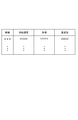
- FIG. 11 shows an example of the measurement result information 336.
- time indicates the elapsed time from the start of moving image shooting, the time when the moving image was taken, and the like.
- the walking speed indicates the speed at which a person walks.
- stride length indicates the length of the toe gap (or heel gap) between the right foot and the left foot when the person walks.
- the straightness indicates the degree of shaking and blurring of the head and body when a person walks.
- the measurement result information 336 may include information indicating a pitch or the like indicating the time required for one step.
- the walking speed and the stride are the information measured by the measured value calculation unit 343 and the measurement unit 344 based on the moving image (image data) of the person walking in the left-right direction. ..
- the straightness is information measured by the measuring unit 344 based on a moving image (image data) in which a person walks in the front-back direction.
- the measurement result information 336 is measured by the measuring unit 344 based on the information measured by the measuring unit 344 based on the moving image of the person walking in the left-right direction and the measuring unit 344 based on the moving image of the person walking in the front-back direction. Information and is included.
- the arithmetic processing unit 340 has a microprocessor such as an MPU and its peripheral circuits.
- the arithmetic processing unit 340 reads the program 337 from the storage unit 330 and executes it, thereby realizing various processing units in cooperation with the hardware and the program 337.
- the main processing units realized by the arithmetic processing unit 340 include, for example, an image acquisition unit 341, a skeleton recognition unit 342, an actual measurement value calculation unit 343, a measurement unit 344, and an output unit 345.
- the image acquisition unit 341 acquires a moving image (a plurality of image data) acquired by the smartphone 200 from the smartphone 200 via the communication I / F unit 320. Then, the image acquisition unit 341 stores the acquired image data in the storage unit 330 as image information 333 in association with, for example, information indicating the acquisition date and time and height of the image data.
- the image acquisition unit 341 associates or supports a moving image (image data) of a person walking in the left-right direction and a moving image (image data) of the person walking in the front-back direction from the smartphone 200. Get it so that it can be attached. Then, the image acquisition unit 341 associates the acquired two types of moving images and stores them in the storage unit 330 as image information 333.
- the skeleton recognition unit 342 uses the trained model 331 to recognize the skeleton of the person whose walking posture is to be measured in the image data. For example, the skeleton recognition unit 342 recognizes each part such as the upper part of the spine, the right shoulder, the left shoulder, the right elbow, the left elbow, the right wrist, the left wrist, the right hand, the left hand, and so on. Further, the skeleton recognition unit 342 calculates the coordinates in the screen data of each recognized part. Then, the skeleton recognition unit 342 stores the recognition / calculation result in the storage unit 330 as skeleton information 334 for each person by associating it with the identification information for identifying the person.
- the portion recognized by the skeleton recognition unit 342 corresponds to the trained model 331 (teacher data used when learning the trained model 331). Therefore, the skeleton recognition unit 342 may recognize a part other than the above-exemplified parts according to the trained model 331.
- the measured value calculation unit 343 has a height h of the camera of the smartphone 200 from the floor surface, a vertical viewing angle ⁇ of the camera of the smartphone 200, a horizontal viewing angle ⁇ , and a reference line screen having an arbitrary height on the screen. Based on the ratio ⁇ from half, the measured value W from one end of the screen to the other of the reference line is calculated. In addition, the measured value calculation unit 343 can calculate the stride length of a person or the like by using the calculated measured value W. Then, the actual measurement value calculation unit 343 stores the calculated actual measurement value W and the like as the actual measurement value information 335 in the storage unit 330. The actual measurement value calculation unit 343 can perform the process of calculating the actual measurement value W for each frame (that is, for each image data) in the moving image.
- the measured value calculation unit 343 makes it possible to calculate the measured value W, which is the actual length (that is, the length in the real world), by using the various values described above.
- FIG. 12 shows a mathematical formula used by the measured value calculation unit 343 to calculate the measured value W.
- the actual measurement value calculation unit 343 calculates the actual measurement value W by solving the equation shown in Equation 1. That is, the measured value calculation unit 343 determines the height h of the camera of the smartphone 200 from the floor surface, the parameters of the camera of the smartphone 200, and the ratio ⁇ from half of the screen of the reference line for calculating the measured value W.
- the measured value W is calculated based on.
- the actually measured value W indicates, for example, the actual length of the reference line in the image data from the screen edge to the edge.
- h is the height of the camera (smartphone 200) from the floor surface.
- the value of height h is input by the photographer when acquiring image data using the height information input unit 2123. Further, ⁇ is a vertical viewing angle, and ⁇ is a horizontal viewing angle. ⁇ is the ratio of the reference line of any height on the screen from half the screen.
- Equation 1 will be described in more detail with reference to FIGS. 13 to 18.
- FIG. 13 it is assumed that a person on a reference line at an arbitrary height on the screen is photographed by using a camera of a smartphone 200 located at a height h.
- the position of the smartphone 200 located at the height h is set as the origin O.
- the point of contact with the floor when the smartphone 200 is lowered vertically toward the floor is defined as the point G
- the position of the person is defined as the point P.
- the angle formed by the line connecting the origin O and the point P and the ground (or a line horizontal to the ground) is defined as an angle ⁇ .
- the angle ⁇ is the ratio of the positions of the arbitrary points P on the screen, and the vertical viewing angle ⁇ is the equation 4.
- FIG. 17 one end of a line having an arbitrary height on the screen passing through the point P is designated as the point Q.
- the number is 6 rather than 5.
- substituting the number 7 into the number 6 gives the number 8.
- the measured value W which is the full length of the horizontal edge of the screen at the distance d from the smartphone 200, is 2w, the above-mentioned number 8 is doubled to the above-mentioned number 1. From the above, it can be seen that the measured value W can be calculated by calculating Equation 1.
- the reference line at an arbitrary height on the screen which is the calculation source of the ratio ⁇
- the actually measured value calculation unit 343 can perform a process of calculating the ratio ⁇ after specifying the reference line based on the position of the foot of the person in the image data.
- the measured value calculation unit 343 can use a line having a slope of 0 passing through the average value of the Y coordinates of the left and right feet of the person, the Y coordinate of any of the feet, and the like as a reference line (other than the example). It doesn't matter).
- the above processing by the actually measured value calculation unit 343 may be performed, for example, for each frame (that is, for each image data). Further, the height of the reference line on the screen may be predetermined according to the position of the guide line 2011 displayed by the guide line display unit 2121 or the like.
- the actual measurement value calculation unit 343 can be calculated by calculating 100 ⁇ k.
- the measured value calculation unit 343 can calculate the stride length based on the calculated measured value W, the resolution, and the number of pixels.
- the actual measurement value calculation unit 343 can calculate the actual measurement value W of the length from the screen edge to the end of the reference line, and can calculate the stride length of the person based on the actual measurement value W. ..
- the measurement unit 344 measures the walking posture of the person by using the calculation result by the actual measurement value calculation unit 343 and the recognition result by the skeleton recognition unit 342. Then, the measurement unit 344 stores the measurement result and the like as the measurement result information 336 in the storage unit 330.
- the measurement unit 344 can perform measurement based on a moving image of a person walking in the left-right direction and measurement based on a moving image of a person walking in the front-back direction.
- the measuring unit 344 can calculate the walking speed, pitch, and the like based on a moving image (image data) of a person walking in the left-right direction.
- the measuring unit 344 calculates the moving distance between frames of the portion recognized by the skeleton recognition unit 342, and calculates the walking speed based on the calculated moving distance and the time of each frame (image data). Can be done.
- the measuring unit 344 may use the calculation result by the measured value calculation unit 343 such as the stride length.
- the measuring unit 344 can calculate the straightness and the like based on the moving image (image data) in which the person walks in the front-back direction. For example, the measuring unit 344 can calculate the straightness based on the fluctuation of the coordinates of the head recognized by the skeleton recognition unit 342.
- the measurement unit 344 may be configured to perform measurements other than those illustrated above.
- the output unit 345 can output the skeleton information 334, the measured value information 335, the measurement result information 336, the moving image included in the image information 333, and the skeleton information 334 superimposed on the moving image.
- the output by the output unit 345 is performed by displaying each of the above information on the screen display unit 310 or transmitting the information to an external device connected via the communication I / F unit 320.
- the above is a configuration example of the walking posture measuring device 300.
- FIG. 20 shows an operation example of the angle adjustment information output unit 2124.
- the angle adjustment information output unit 2124 corrects the pitch according to the tilt (step S102). That is, the angle adjustment information output unit 2124 corrects the pitch more greatly as the smartphone 200 is tilted toward the front or the back. Then, the angle adjustment information output unit 2124 outputs the corrected sound (step S103).
- the angle adjustment information output unit 2124 corrects the sound length according to the tilt (step S102). That is, the angle adjustment information output unit 2124 corrects the length of the sound more as the smartphone 200 is tilted to the left or right. Then, the angle adjustment information output unit 2124 outputs the corrected sound (step S103).
- the sound output by the angle adjustment information output unit 2124 ends when the end condition is satisfied (step S107, Yes).
- the conditions for termination include, for example, that the shooting of the moving image has started, the shooting of the moving image has ended, a predetermined time has passed since the tilt of the smartphone 200 disappeared and the sounds matched, and the output was stopped by a person. And so on.
- the conditions for termination may be other than those illustrated above.
- the image acquisition unit 341 acquires a moving image (a plurality of image data) acquired by the smartphone 200 from the smartphone 200 via the communication I / F unit 320 (step S201).
- the image acquisition unit 341 associates or supports a moving image (image data) of a person walking in the left-right direction and a moving image (image data) of the person walking in the front-back direction from the smartphone 200. Get it so that it can be attached.
- the skeleton recognition unit 342 recognizes the skeleton of the person whose walking posture is to be measured in the image data by using the trained model 331 (step S202).
- the measuring unit 344 acquires the measured value W or the like indicated by the measured value information 335 (step S203).
- the actual measurement value W indicated by the actual measurement value information 335 may be calculated in advance by the actual measurement value calculation unit 343, for example, in parallel with the skeleton recognition process by the skeleton recognition unit 342, or by the skeleton recognition unit. After the recognition process by 342, it may be calculated by the actual measurement value calculation unit 343.
- the measurement unit 344 measures the walking posture of the person by using the calculation result by the actual measurement value calculation unit 343 (step S204). For example, the measurement unit 344 performs measurement based on a moving image of a person walking in the left-right direction and measurement based on a moving image of a person walking in the front-back direction.
- the output unit 345 outputs the skeleton information 334, the measured value information 335, the measurement result information 336, the moving image included in the image information 333, and the skeleton information 334 superimposed on the moving image (step S205).
- the measured value calculation unit 343 acquires information indicating the height input by the height information input unit 2123 included in the image information 333. Further, the measured value calculation unit 343 acquires information indicating the vertical viewing angle ⁇ and the horizontal viewing angle ⁇ of the camera with reference to the camera setting information 332 (step S301).
- the measured value calculation unit 343 determines the reference line for calculating the measured value W and calculates the ratio ⁇ (step S302). For example, the measured value calculation unit 343 specifies the reference line based on the position of the foot of a person in the image data. Further, the measured value calculation unit 343 calculates the ratio ⁇ from the half of the screen of the reference line based on the specified reference line.
- the measured value calculation unit 343 calculates the measured value W based on the height h, the vertical viewing angle ⁇ , the horizontal viewing angle ⁇ , and the ratio ⁇ (step S303). For example, the actually measured value calculation unit 343 calculates the actually measured value W by solving the equation shown by the above-mentioned equation 1. Then, the actual measurement value calculation unit 343 stores the calculated actual measurement value W as the actual measurement value information 335 in the storage unit 330.
- the measured value calculation unit 343 takes the difference between the x-coordinate values of the left and right feet (for example, the toes) in the image data. Then, the stride is calculated based on the difference between the x-coordinate values, the actually measured value W, and the resolution (step S304).
- the above is a processing example of the measured value calculation unit 343.
- the walking posture measuring device 300 has a skeleton recognition unit 342 and a measuring unit 344. According to such a configuration, the measuring unit 344 can measure the walking posture based on the result of the skeleton recognition by the skeleton recognition unit 342. As a result, the measuring unit 344 can measure the walking posture based on the image data acquired by using the camera or the like of the smartphone 200 without using the depth sensor or the like.
- the walking posture measuring device 300 is configured to acquire a moving image showing a person walking in the front-back direction of the image and a moving image showing a person walking in the left-right direction of the image.
- the measuring unit 344 performs measurement based on a moving image showing a person walking in the front-back direction of the image, and also performs measurement based on a moving image showing a person walking in the left-right direction of the image. Can be done.
- the measuring unit 344 can measure various walking postures, which is difficult from one moving image, based on the image data acquired by using the camera or the like of the smartphone 200 without using the depth sensor or the like.
- the walking posture measuring device 300 has an actually measured value calculation unit 343. According to such a configuration, the measured value calculation unit 343 can calculate the measured value. As a result, it becomes possible to calculate the stride length and the like based on the moving image taken by the camera of the smartphone 200. As a result, the walking posture measuring device 300 can accurately measure the walking posture based on the moving image taken by the camera of the smartphone 200.
- the smartphone 200 has a shooting assistance unit 212.
- the smartphone 200 includes a video showing a person walking in the front-back direction of the image and a video showing a person walking in the left-right direction of the image with the assistance of the shooting assistance unit 212. Can be obtained.
- the smartphone 200 can acquire the above two types of moving images while keeping the shooting conditions as close as possible. Thereby, when the measurement using two kinds of moving images is performed, the accuracy of the measurement by the measuring unit 344 can be improved.
- the photographing auxiliary unit 212 has an angle adjustment information output unit 2124.
- the angle adjustment information output unit 2124 can output information such as a sound for adjusting the inclination of the smartphone 200.
- the angle of the smartphone 200 can be easily adjusted even when it is difficult to see the screen of the smartphone 200.
- the photographing device included in the walking posture measuring system 100 is not limited to the smartphone 200.
- the function as the walking posture measuring device 300 is realized by one information processing device.
- the function of the walking posture measuring device 300 may be realized by, for example, a plurality of information processing devices connected via a network.
- the function of the walking posture measuring device 300 is not limited to the case where it is realized by one information processing device, and may be realized, for example, on the cloud.
- the photographing assisting unit 212 may have all of the plurality of functions illustrated in FIG. 5, or may have some (at least one) of the functions illustrated in FIG.
- the photographing assisting unit 212 may have only the function as the angle adjustment information output unit 2124 without displaying the angle information 2012 by the angle information display unit 2122.
- the auxiliary function by the photographing assisting unit 212 described in the present embodiment may be applied to a system other than the walking posture measurement system 100.
- the auxiliary function by the shooting auxiliary unit 212 may be applied to various scenes in which it is necessary to arrange the shooting conditions as much as possible when acquiring the image data.
- the calculation process of the actual measurement value W by the actual measurement value calculation unit 343 may be applied to a system other than the walking posture measurement system 100.
- the calculation process of the measured value W by the measured value calculation unit 343 can be applied to various situations in which the measured value is calculated based on the image data.
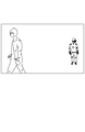
- FIG. 23 is a diagram for explaining a tracking example of the walking posture measuring device 300.
- FIG. 24 is a block diagram showing a configuration example of the walking posture measuring device 300 according to the second embodiment.
- FIG. 25 is a diagram showing a configuration example of the tracking unit 346.
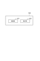
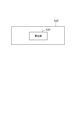
- 26 and 27 are diagrams showing an example of a figure generated by the inclusion figure generation unit 3461.
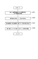
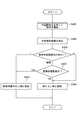
- FIG. 28 is a flowchart showing an operation example of the tracking unit 346.
- the tracking unit 346 is provided.
- the tracking unit 346 is configured to perform tracking based on the result of recognition by the skeletal recognition unit 342.
- FIG. 24 shows a configuration example of the walking posture measuring device 300 according to the second embodiment.
- the walking posture measuring device 300 has a tracking unit 346 in addition to the configuration described in the first embodiment.
- a configuration characteristic of the present embodiment will be described.
- the tracking unit 346 tracks the person based on the recognition result by the skeleton recognition unit 342. For example, the tracking unit 346 tracks a person by assigning a recognition number to the recognized person. That is, the tracking unit 346 tracks the person by assigning the same recognition number to the person determined to be the same between the image data one frame before and the image data of the current frame.
- FIG. 25 shows a more detailed configuration example of the tracking unit 346. Referring to FIG. 25, the tracking unit 346 includes, for example, an inclusion figure generation unit 3461, an average skeleton coordinate calculation unit 3462, and a comparison tracking unit 3464.
- the inclusion figure generation unit 3461 generates a figure including the coordinates of all the parts recognized by the skeleton recognition unit 342 (coordinates included in the skeleton information 334) for each person. For example, the inclusion figure generation unit 3461 generates one of the smallest, convex hull, rectangle, and circle that includes all the coordinates. In addition, the inclusion figure generation unit 3461 calculates the area of the generated figure.
- the inclusion figure generation unit 3461 performs the generation of the inclusion figure and the calculation process of the area for the image data of each frame.
- the inclusion figure generation unit 3461 performs the generation of the inclusion figure and the calculation process of the area for each of the plurality of persons included in the image data.
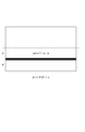
- FIG. 26 shows an example of a figure including the coordinates of a person walking in the front-back direction of the screen.
- the inclusion figure generation unit 3461 can generate any of the smallest convex hulls, rectangles, and circles that include all the coordinates.
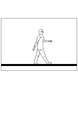
- FIG. 27 shows an example of a figure including the coordinates of a person walking in the left-right direction of the screen. In the case shown in FIG. 27 as in the case shown in FIG. 26, the inclusion figure generation unit 3461 can generate any one of the smallest convex hull, rectangle, and circle that includes all the coordinates.
- the inclusion figure generation unit 3461 is predetermined, for example.
- the inclusion figure generation unit 3461 is defined to generate a circle as a figure containing coordinates.
- the average skeleton coordinate calculation unit 3462 calculates the average value of the coordinates (coordinates included in the skeleton information 334) of all the parts recognized by the skeleton recognition unit 342 for each person. As a result, the average skeleton coordinate calculation unit 3462 calculates the average skeleton coordinates based on the coordinates of each part of the person recognized by the skeleton recognition unit 342.
- the average skeleton coordinate calculation unit 3462 performs the calculation process of the average skeleton coordinates for the image data of each frame.
- the average skeleton coordinate calculation unit 3462 performs the calculation process of the average skeleton coordinates for each of the plurality of persons included in the image data.
- the comparison tracking unit 3464 tracks a person based on the area of the included figure calculated by the inclusion figure generation unit 3461 and the average skeleton coordinates calculated by the average skeleton coordinate calculation unit 3462. For example, the comparison tracking unit 3464 compares the area corresponding to the person to be tracked calculated in the current frame and the area calculated one frame before. Further, the comparison tracking unit 3464 performs a comparison between the average skeleton coordinates corresponding to the person to be tracked and the average skeleton coordinates calculated one frame before, according to the result of the comparison.
- the comparison tracking unit 3464 determines that the person one frame before and the person in the current frame whose area difference belongs to the first allowable value are the same person. As a result, the comparison tracking unit 3464 sets, for example, the recognition number corresponding to the person one frame before determined to be the same as the recognition number corresponding to the person in the current frame.
- the comparison tracking unit 3464 has a difference between the average skeleton coordinates of the person to be tracked and the area. A comparison is made with the average skeletal coordinates of the person one frame before, which was within the first permissible value. Then, the comparison tracking unit 3464 determines that the person one frame before and the person in the current frame whose difference in the average skeleton coordinates belongs to the second allowable value are the same person. As a result, the comparison tracking unit 3464 sets, for example, the recognition number corresponding to the person one frame before determined to be the same person as the recognition number corresponding to the person in the current frame.
- the comparison tracking unit 3464 determines that the person whose average skeleton coordinate difference is closest to the second allowable value is the same person. Can be done.
- the comparison tracking unit 3464 may be configured to perform a process other than the above example, such as determining an error.
- the comparison tracking unit 3464 determines that the person to be tracked is a newly recognized person. In this case, the comparison tracking unit 3464 assigns a new recognition number to the newly recognized person.
- the comparison tracking unit 3464 can use, as the first allowable value, an estimated area value estimated based on the rate of increase / decrease in the area corresponding to the person determined to be the same person in the past several frames. ..
- the first permissible value may be a predetermined value.
- the comparison tracking unit 3464 can use, as the second allowable value, an estimated coordinate value estimated from the moving speed of the average skeleton coordinates corresponding to the person determined to be the same person in the past several frames.
- the second permissible value may be a predetermined value like the first permissible value.
- the above is a configuration example of the tracking unit 346. Subsequently, an operation example of the tracking unit 346 will be described with reference to FIG. 28.
- the inclusion figure generation unit 3461 generates a figure including the coordinates of all the parts recognized by the skeleton recognition unit 342 (coordinates included in the skeleton information 334) for each person. In addition, the inclusion figure generation unit 3461 calculates the area of the generated figure (step S401).
- the average skeleton coordinate calculation unit 3462 calculates the average skeleton coordinates by calculating the average value of the coordinates (coordinates included in the skeleton information 334) of all the parts recognized by the skeleton recognition unit 342 for each person (step S402). ).
- the comparison tracking unit 3464 compares the area corresponding to the person to be tracked calculated in the current frame and the area calculated one frame before (step S403).
- the comparative tracking unit. 3463 determines that the person one frame before and the person in the current frame whose area difference belongs to the first permissible value are the same person (step S404). As a result, the comparison tracking unit 3464 sets the recognition number corresponding to the person one frame before as the recognition number of the current frame, for example.
- the comparative tracking unit 3464 has the average skeletal coordinates of the person to be tracked. And the average skeleton coordinates of the person one frame before the difference in area was within the first permissible value (step S405). Then, when there is a person whose difference from the average skeleton coordinates of the tracking target is within the second allowable value one frame before (step S405, Yes), the comparative tracking unit 3464 is the person one frame before and the tracking target. It is determined that the person is the same person (step S404).
- the comparison tracking unit 3464 uses, for example, the same person whose difference is closest to the second allowable value. It can be judged that it is a person. Further, when there is no person whose difference from the average skeleton coordinates of the tracking target is within the second allowable value one frame before (step S405, No), the comparative tracking unit 3464 newly recognizes the person to be tracked. It is determined that the person is a person (step S406). In this case, the comparison tracking unit 3464 assigns a new recognition number to the newly recognized person.
- the comparative tracking unit 3464 newly sets the person to be tracked. (Step S406). In this case, the comparison tracking unit 3464 assigns a new recognition number to the newly recognized person.
- the above is an operation example of the tracking unit 346.
- the walking posture measuring device 300 in the present embodiment has a tracking unit 346.
- the tracking unit 346 can track the same person based on the recognition result by the skeleton recognition unit 342. As a result, it is possible to suppress the erroneous calculation of the walking speed, and it is possible to improve the accuracy of the walking posture measurement.
- the inclusion figure generation unit 3461 may be configured to calculate a value other than the area based on the generated inclusion figure.
- the inclusion figure generation unit 3461 may calculate the height, diameter, and the like of the generated inclusion figure instead of the area.
- the comparison tracking unit 3464 will compare values such as the height calculated based on the figure generated by the inclusion figure generation unit 3461 instead of the area.
- the inclusion figure generation unit 3461 is supposed to generate a figure included in all coordinates.
- the included figure generation unit 3461 may be configured to generate a figure including a part of the coordinates recognized by the skeleton recognition unit 342, for example, generating a figure included in the coordinates corresponding to the upper body of the person. I do not care.
- the average skeleton coordinate calculation unit 3462 may also calculate the average coordinates based on a part of the coordinates recognized by the skeleton recognition unit 342, such as the average coordinates of the coordinates corresponding to the upper body of the person.
- comparison tracking unit 3464 may be configured to perform only one of the comparison of the values based on the inclusion figure generated by the inclusion figure generation unit 3461 and the comparison of the average skeleton coordinates.
- the tracking using the recognition result by the skeleton recognition unit 342 described in the present embodiment may be applied to the case of tracking a person other than the scene of measuring the walking posture. That is, the function as the tracking unit 346 may be applied to a device other than the walking posture measuring device 300 that requires tracking a person.
- the method of tracking a person using skeletal information described in the present embodiment is not limited to the case of measuring the walking posture, and can be used in various situations.
- FIGS. 29 and 30 show a configuration example of the photographing apparatus 400.
- the photographing device 400 photographs a person walking.
- FIG. 29 shows an example of the hardware configuration of the photographing device 400.
- the photographing apparatus 400 has the following hardware configuration as an example in addition to a camera for performing photographing.
- -CPU Central Processing Unit
- -ROM Read Only Memory
- RAM Random Access Memory
- storage device storage device
- -Program group 404 loaded into RAM 403
- a storage device 405 that stores a program group 404.
- -Drive device 406 that reads and writes the recording medium 410 external to the information processing device.
- -Communication interface 407 that connects to the communication network 411 outside the information processing device -I / O interface 408 that inputs and outputs data -Bus 409 connecting each component
- the photographing device 400 can realize the functions as the detection unit 421 and the display unit 422 shown in FIG. 30 by the CPU 401 acquiring the program group 404 and executing the program group 404.
- the program group 404 is stored in, for example, a storage device 405 or a ROM 402 in advance, and the CPU 401 loads the program group 404 into a RAM 403 or the like and executes the program group 404 as needed. Further, the program group 404 may be supplied to the CPU 401 via the communication network 411, or may be stored in the recording medium 410 in advance, and the drive device 406 may read the program and supply the program to the CPU 401.
- FIG. 29 shows an example of the hardware configuration of the photographing device 400.
- the hardware configuration of the photographing device 400 is not limited to the above-mentioned case.
- the photographing device 400 may be composed of a part of the above-described configuration, such as not having the drive device 406.
- the detection unit 421 detects the orientation of the photographing device 400. For example, the detection unit 421 detects whether the photographing device 400 is in the vertical orientation or in the horizontal orientation.
- the display unit 422 displays a guide line indicating the position where the person walks on the screen display unit. For example, the display unit 422 displays different guide lines according to the orientation of the photographing device 400 detected by the detection unit 421.
- the photographing device 400 has a detection unit 421 and a display unit 422.
- the display unit 422 can display different guide lines according to the orientation of the photographing device 400 detected by the detection unit 421.
- the display unit 422 can display different guide lines according to the orientation of the photographing device 400 detected by the detection unit 421.
- the above-mentioned photographing device 400 can be realized by incorporating a predetermined program into the photographing device 400.
- the photographing device 400 has a detection unit 421 that detects the direction of the photographing device and a display unit that displays a guide line indicating a position where a person walks on the screen display unit.
- the display unit 422 is a program that realizes 422 and displays the guide lines that differ depending on the orientation of the photographing device detected by the detection unit 421.
- the photographing device 400 that photographs the state of walking of a person detects the direction of the photographing device and displays a guide line indicating the position where the person walks on the screen display unit.
- a different guide line is displayed according to the detected orientation of the photographing device.
- FIG. 31 shows A configuration example of the information processing device 500 is shown.
- the information processing device 500 has, for example, a configuration similar to the hardware configuration of the photographing device 400 described with reference to FIG. 29. Further, the information processing device 500 can realize the function as the calculation unit 521 shown in FIG. 31 by the CPU acquiring the program group included in the information processing device 500 and executing the program group by the CPU.
- the calculation unit 521 calculates the actual length at a predetermined position in the image data based on the parameters of the photographing device for acquiring the image data and the information indicating the height of the photographing device when acquiring the image data. do.
- the information processing device 500 has a calculation unit 521.
- the calculation unit 521 can calculate the actual length at a predetermined position in the image data based on various information. As a result, it becomes possible to perform analysis using the actual length based on the image data acquired by a photographing device such as a smartphone.
- the information processing device 500 described above can be realized by incorporating a predetermined program into the information processing device 500.
- the program according to another embodiment of the present invention provides the information processing device 500 with information indicating the parameters of the photographing device for acquiring image data and the height of the photographing device when acquiring the image data. Based on this, it is a program for realizing the calculation unit 521 that calculates the actual length at a predetermined position in the image data.
- the information processing device 500 obtains the parameters of the photographing device for acquiring the image data and the information indicating the height of the photographing device when acquiring the image data. It is a method of acquiring and calculating the actual length at a predetermined position in the image data based on the acquired information.
- FIG. 32 shows a configuration example of the information processing device 600.
- the information processing device 600 has, for example, a configuration similar to the hardware configuration of the photographing device 400 described with reference to FIG. 29. Further, the information processing device 600 can realize the functions as the detection unit 621 and the output unit 622 shown in FIG. 32 by the CPU acquiring the program group possessed by the information processing device 600 and executing the program group by the CPU. You can.
- the detection unit 621 detects the tilt of the information processing device.
- the output unit 622 outputs information according to the inclination of the information processing device detected by the detection unit 621, which differs depending on the inclination of the information processing device.
- the information processing device 600 has a detection unit 621 and an output unit 622. According to such a configuration, the output unit 622 can output information according to the inclination of the information processing device detected by the detection unit 621. As a result, the operator who operates the information processing apparatus 600 can correct the inclination according to the output information.
- the information processing device 600 described above can be realized by incorporating a predetermined program into the information processing device 600.
- the information processing device 600 has a detection unit 621 that detects the tilt of the information processing device 600 and a detection unit 621 that differs depending on how the information processing device 600 is tilted.
- This is a program for realizing an output unit 622 that outputs information according to the inclination of the information processing apparatus 600 detected by the information processing apparatus 600.
- the information processing device 600 detects the tilt of the information processing device 600, and the detected tilt of the information processing device differs depending on how the information processing device is tilted. It is a method of outputting information according to.
- FIG. 33 shows a configuration example of the tracking device 700.
- the tracking device 700 has, for example, a configuration similar to the hardware configuration of the photographing device 400 described with reference to FIG. 29. Further, the tracking device 700 can realize the functions as the acquisition unit 721 and the tracking unit 722 shown in FIG. 33 by the CPU acquiring the program group included in the tracking device 700 and executing the program group.
- the acquisition unit 721 acquires information indicating a plurality of parts of the recognized person by recognizing the skeleton of the person in the image data.
- the tracking unit 722 tracks the same person among a plurality of image data based on the information acquired by the acquisition unit 721.
- the tracking device 700 has an acquisition unit 721 and a tracking unit 722. With such a configuration, the tracking unit 722 can perform tracking based on the information indicating the portion acquired by the acquisition unit 721. This makes it possible to realize easy tracking.
- the tracking device 700 described above can be realized by incorporating a predetermined program into the tracking device 700.
- the tracking device 700 has an acquisition unit 721 that acquires information indicating a plurality of recognized parts of the person by recognizing the skeleton of the person in the image data.
- This is a program for realizing a tracking unit 722 that tracks the same person among a plurality of image data based on the information acquired by the acquisition unit 721.
- the tracking device 700 acquires information indicating a plurality of parts of the recognized person by recognizing the skeleton of the person in the image data, and the acquired information is used. Based on this, it is a method of tracking the same person among a plurality of image data.
- Appendix 1 A shooting device that shoots a person walking Detects the orientation of the shooting device and A guide line indicating the position where the person walks is displayed on the screen display.
- a guide method for displaying the guide lines that differ depending on the direction of the detected photographing device when the guide lines are displayed on the screen display unit.
- Appendix 2 The guide method described in Appendix 1 A guide method for displaying different guide lines depending on whether the photographing device is in portrait orientation or landscape orientation.
- Appendix 3) The guide method described in Appendix 1 or Appendix 2, A guide method for displaying the guide line for guiding a person walking in the front-back direction of the screen when the photographing device is oriented vertically.
- Appendix 7 The guide method described in Appendix 6 A guide method that detects the tilt in the left-right direction and the tilt in the front-back direction, and outputs different information when the tilt in the left-right direction is detected and when the tilt in the front-back direction is detected.
- Appendix 8 The guide method according to Appendix 6 or Appendix 7. A guide method that outputs the sound adjusted by different methods when the tilt in the left-right direction is detected and when the tilt in the front-back direction is detected.
- Appendix 9 It is a shooting device that shoots a person walking.
- the display unit is an imaging device that displays different guide lines according to the orientation of the imaging device detected by the detection unit. (Appendix 10) For a shooting device that shoots a person walking A detector that detects the orientation of the imaging device and A display unit that displays a guide line indicating the position where a person walks on the screen display unit, Realized,
- the display unit is a program that displays the guide lines that differ depending on the orientation of the photographing device detected by the detection unit.
- (Appendix 11) Information processing device The parameters of the photographing device for acquiring the image data and the information indicating the height of the photographing device when acquiring the image data are acquired, and based on the acquired information, the actual length at a predetermined position in the image data is obtained. Calculation method to calculate.
- Information processing device (Appendix 20) For information processing equipment Realized a calculation unit that calculates the actual length at a predetermined position in the image data based on the parameters of the imaging device that acquires the image data and the information that indicates the height of the imaging device when acquiring the image data. Program to do. (Appendix 21) Information processing device Detects the tilt of the information processing device and An output method that outputs information according to the tilt of the information processing device, which differs depending on the tilt of the information processing device.
- Appendix 22 The output method described in Appendix 21. Detects the tilt of the information processing device in the left-right direction and the tilt in the front-back direction, An output method that outputs different information when the tilt in the left-right direction is detected and when the tilt in the front-back direction is detected.
- Appendix 23 The output method according to Appendix 21 or Appendix 22. An output method that outputs sound adjusted by different methods when the tilt in the left-right direction is detected and when the tilt in the front-back direction is detected.
- Appendix 24 The output method described in Appendix 23.
- Appendix 27 A detector that detects the tilt of the information processing device and An output unit that outputs information according to the inclination of the information processing device detected by the detection unit, which differs depending on the inclination of the information processing device.
- Information processing device with. (Appendix 28) The information processing device according to Appendix 27.
- the detection unit detects the tilt of the information processing device in the left-right direction and the tilt in the front-back direction.
- the output unit is an information processing device that outputs different information depending on whether the detection unit detects a tilt in the left-right direction or a tilt in the front-back direction.
- Appendix 29 For information processing equipment A detector that detects the tilt of the information processing device and An output unit that outputs information according to the inclination of the information processing device detected by the detection unit, which differs depending on the inclination of the information processing device. A program to realize.
- Appendix 30 The program described in Appendix 29.
- the detection unit detects the tilt of the information processing device in the left-right direction and the tilt in the front-back direction.
- the output unit is a program that outputs different information depending on whether the detection unit detects a tilt in the left-right direction or a tilt in the front-back direction.
- Information processing device By recognizing the skeleton of a person in the image data, information indicating multiple parts of the recognized person is acquired, and information is obtained.
- a tracking method that tracks the same person among multiple image data based on the acquired information (Appendix 32) The tracking method described in Appendix 31. Generate an inclusion figure that includes at least a part of the recognized part, A tracking method for tracking the same person based on a value corresponding to the generated inclusion figure. (Appendix 33) The tracking method described in Appendix 32. A tracking method for tracking the same person based on the difference in values between image data according to the included figure. (Appendix 34) The tracking method described in Appendix 33. The number at which the difference between the value corresponding to the included figure of the tracking target and the value corresponding to the included figure corresponding to the person included in the image data different from the image data to which the tracking target belongs is within a predetermined value.
- a tracking method that determines that a person whose difference is within a predetermined value is the same person as the person to be tracked.
- the predetermined value is a tracking method determined according to the degree of change in the value according to the included figure among a plurality of image data.
- Appendix 36 The tracking method according to any one of Appendix 31 to Appendix 35. Calculate the average value of the coordinates of at least a part of the coordinates of the recognized part, A tracking method that tracks the same person based on the calculated results.
- Appendix 37 The tracking method described in Appendix 36. A tracking method for tracking the same person based on the difference in the average value between image data.
- Appendix 38 The tracking method according to Appendix 36 or Appendix 37.
- Appendix 39 An acquisition unit that acquires information indicating multiple parts of the recognized person by recognizing the skeleton of the person in the image data, and an acquisition unit.
- a tracking unit that tracks the same person among a plurality of image data based on the information acquired by the acquisition unit.
- Appendix 40 In the tracking device, An acquisition unit that acquires information indicating multiple parts of the recognized person by recognizing the skeleton of the person in the image data, and an acquisition unit.
- the programs described in each of the above embodiments and appendices may be stored in a storage device or recorded in a computer-readable recording medium.
- the recording medium is a portable medium such as a flexible disk, an optical disk, a magneto-optical disk, and a semiconductor memory.
Landscapes
- Engineering & Computer Science (AREA)
- Computer Vision & Pattern Recognition (AREA)
- Physics & Mathematics (AREA)
- General Physics & Mathematics (AREA)
- Theoretical Computer Science (AREA)
- Multimedia (AREA)
- Measurement Of The Respiration, Hearing Ability, Form, And Blood Characteristics Of Living Organisms (AREA)
Abstract
追跡装置700は、画像データ中の人物の骨格を認識することにより認識した人物の複数の部位を示す情報を取得する取得部721と、取得部721が取得した情報に基づいて、複数の画像データ間における同一人物の追跡を行う追跡部722と、を有する。
Description
本発明は、追跡方法、追跡装置、記録媒体に関する。
データに基づいてユーザの歩行分析を行うことが知られている。
人物の歩行分析について記載された文献として、例えば、特許文献1がある。特許文献1には、デプスセンサから2種類の画像データを取得するデータ取得部と、データ取得部が取得した画像データに基づいて骨格情報を作成する骨格情報作成部と、骨格情報作成部が作成した骨格情報を補正する補正処理部と、補正後の骨格情報を用いてユーザの歩行を分析する分析処理部と、を有する歩行分析装置が記載されている。
特許文献1に記載されている技術では、デプスセンサ(3Dセンサ)を用いることが必須となるが、デプスセンサなどの3Dセンサを用いずに、カメラが取得した画像データに基づいて歩行分析を行いたいというニーズがある。
ここで、画像データに基づく歩行分析などの分析を行う場合、同一人物の追跡をきちんと行わないと、例えば歩行速度の算出など複数の画像データにまたがる分析を行う際に、精度が落ちることがある。そのため、容易な方法で追跡を行うことが好ましいが、状況によっては、画像データ間で同一人物の追跡を行うことが難しい場合があった。
このように、画像データ間において同一人物の追跡を行うことが難しい場合がある、という課題が生じていた。
そこで、本発明の目的は、画像データ間において同一人物の追跡を行うことが難しい場合がある、という課題を解決する追跡方法、追跡装置、記録媒体を提供することにある。
かかる目的を達成するため本開示の一形態である追跡方法は、
情報処理装置が、
画像データ中の人物の骨格を認識することにより認識した人物の複数の部位を示す情報を取得し、
取得した情報に基づいて、複数の画像データ間における同一人物の追跡を行う
という構成をとる。
情報処理装置が、
画像データ中の人物の骨格を認識することにより認識した人物の複数の部位を示す情報を取得し、
取得した情報に基づいて、複数の画像データ間における同一人物の追跡を行う
という構成をとる。
また、本開示の他の形態である追跡装置は、
画像データ中の人物の骨格を認識することにより認識した人物の複数の部位を示す情報を取得する取得部と、
前記取得部が取得した情報に基づいて、複数の画像データ間における同一人物の追跡を行う追跡部と、
を有する
という構成をとる。
画像データ中の人物の骨格を認識することにより認識した人物の複数の部位を示す情報を取得する取得部と、
前記取得部が取得した情報に基づいて、複数の画像データ間における同一人物の追跡を行う追跡部と、
を有する
という構成をとる。
また、本開示の他の形態である記録媒体は、
追跡装置に、
画像データ中の人物の骨格を認識することにより認識した人物の複数の部位を示す情報を取得する取得部と、
前記取得部が取得した情報に基づいて、複数の画像データ間における同一人物の追跡を行う追跡部と、
を実現するためのプログラムを記録した、コンピュータが読み取り可能な記録媒体である。
追跡装置に、
画像データ中の人物の骨格を認識することにより認識した人物の複数の部位を示す情報を取得する取得部と、
前記取得部が取得した情報に基づいて、複数の画像データ間における同一人物の追跡を行う追跡部と、
を実現するためのプログラムを記録した、コンピュータが読み取り可能な記録媒体である。
上述したような各構成によると、画像データ間において同一人物の追跡を行うことが可能となる。
[第1の実施形態]
本開示の第1の実施形態について、図1から図22までを参照して説明する。図1は、歩行姿勢測定システム100の構成例を示す図である。図2は、手前奥方向の歩行姿勢を撮影する際の一例を示す図である。図3は、左右方向の歩行姿勢を撮影する際の一例を示す図である。図4は、スマートフォン200の構成例を示すブロック図である。図5は、撮影補助部212の構成例を示すブロック図である。図6は、横持ち時の撮影補助表示例を示す図である。図7は、縦持ち時の撮影補助表示例を示す図である。図8は、角度調整情報出力部2124の動作例を示す図である。図9は、歩行姿勢測定装置300の構成例を示すブロック図である。図10は、骨格情報334の一例を示す図である。図11は、測定結果情報336の一例を示す図である。図12は、実測値算出部343の処理を説明するための図である。図13から図19までは、実測値算出部343の処理を説明するための図である。図20は、スマートフォン200における撮影補助部212の動作例を示すフローチャートである。図21は、歩行姿勢測定装置300の動作例を示すフローチャートである。図22は、実測値情報335を算出する処理の一例を示すフローチャートである。
本開示の第1の実施形態について、図1から図22までを参照して説明する。図1は、歩行姿勢測定システム100の構成例を示す図である。図2は、手前奥方向の歩行姿勢を撮影する際の一例を示す図である。図3は、左右方向の歩行姿勢を撮影する際の一例を示す図である。図4は、スマートフォン200の構成例を示すブロック図である。図5は、撮影補助部212の構成例を示すブロック図である。図6は、横持ち時の撮影補助表示例を示す図である。図7は、縦持ち時の撮影補助表示例を示す図である。図8は、角度調整情報出力部2124の動作例を示す図である。図9は、歩行姿勢測定装置300の構成例を示すブロック図である。図10は、骨格情報334の一例を示す図である。図11は、測定結果情報336の一例を示す図である。図12は、実測値算出部343の処理を説明するための図である。図13から図19までは、実測値算出部343の処理を説明するための図である。図20は、スマートフォン200における撮影補助部212の動作例を示すフローチャートである。図21は、歩行姿勢測定装置300の動作例を示すフローチャートである。図22は、実測値情報335を算出する処理の一例を示すフローチャートである。
本開示の第1の実施形態においては、スマートフォン200などの撮影装置を用いて取得した動画に基づいて、人物の歩行姿勢を測定する歩行姿勢測定システム100について説明する。歩行姿勢測定システム100では、スマートフォン200を用いて、画像の手前奥方向に人物が歩く様子を示す動画(つまり、複数の画像データ)と、画像の左右方向に人物が歩く様子を示す動画と、を撮影する。そして、歩行姿勢測定システム100は、撮影により取得した動画である複数の画像データに基づいて、歩幅、歩行速度、歩行時の頭などのブレに応じた直進性、などの歩行姿勢を測定する。また、歩行姿勢測定システム100は、後述するように、スマートフォン200を用いて画像データを取得する際に撮影条件を出来る限り揃えるための仕組みや画像データから実測値を測定するための仕組みなどを含んでいる。
図1は、歩行姿勢測定システム100の構成例を示している。図1を参照すると、歩行姿勢測定システム100は、例えば、スマートフォン200と、歩行姿勢測定装置300と、を有している。図1で示すように、スマートフォン200と歩行姿勢測定装置300とは、例えば、無線、または、有線により、互いに通信可能なよう接続されている。
スマートフォン200は、人物が歩く様子を撮影する撮影装置として機能する。スマートフォン200は、カメラ機能、画面表示を行うタッチパネル201、GPSセンサや加速度センサなどの各種センサ、などの一般的な機能を有するスマートフォンであって構わない。
本実施形態の場合、図2で示すように、スマートフォン200を縦向きで持った状態(縦持ちした状態)で、画面奥から手前など人物が手前奥方向に歩く様子を撮影者が撮影する。換言すると、矩形形状を有するスマートフォン200のうち短辺が地面と水平になる縦持ちをした状態で、人物が手前奥方向に歩く様子を撮影者が撮影する。また、図3で示すように、スマートフォン200を横向きで持った状態(横持ちした状態)で、画面左から右など人物が左右方向に歩く様子を撮影者が撮影する。換言すると、スマートフォン200のうち長辺が地面と水平になる横持ちをした状態で、人物が手前奥方向に歩く様子を撮影者が撮影する。このように、歩行姿勢測定システム100においては、スマートフォン200の向きに応じた種類の動画(複数の画像データ)を撮影者が撮影する。なお、人物が手前奥方向に歩く様子と人物が左右方向に歩く様子とは、例えば、1台のスマートフォン200を用いて2回に分けて撮影しても構わないし、2台のスマートフォン200を用いて同時に撮影しても構わない。
図4は、スマートフォン200の本実施形態において特徴的な構成例を示している。図4を参照すると、スマートフォン200は、スマートフォン200の向き(縦向き、横向き)を検出するための加速度センサやジャイロセンサなどのスマートフォンとして一般的な構成に加えて、測定用動作撮影部210を有している。また、図4で示すように、測定用動作撮影部210は、画像データ撮影部211と、撮影補助部212と、を含んでいる。
例えば、スマートフォン200は、CPU(Central Processing Unit)などの演算装置と記憶装置とを有している。スマートフォン200は、例えば、記憶装置に格納されたプログラムを演算装置が実行することで、上述した処理部を実現する。
測定用動作撮影部210は、撮影者のスマートフォン200に対する操作に応じて、本実施形態における測定用動作である、人物が歩く様子を撮影する。また、測定用動作撮影部210は、撮影を行う際に出来る限り同じ条件で撮影可能なよう、撮影を補助するための機能を含んでいる。例えば、測定用動作撮影部210は、人物が歩く様子を撮影するためのカメラ操作機能を有するとともに、人物が歩く様子を撮影する際に、歩く方向、角度、画面に映る大きさ、などの撮影条件を出来る限り揃えるためのガイド機能を有する撮影用アプリである。上述したように、測定用動作撮影部210は、画像データ撮影部211と、撮影補助部212と、を含んでいる。
画像データ撮影部211は、スマートフォン200が有するカメラを利用して人物を撮影することで、動画(複数の画像データ)を取得する。また、画像データ撮影部211は、当該画像データ撮影部211が撮影した動画(画像データ)に、画像データの取得日時を示す情報や、後述する撮影補助部212が取得した情報などを対応づけることが出来る。
撮影補助部212は、画像データ撮影部211が画像データを取得する際に撮影条件を出来る限り揃えるための補助を行う。図5は、撮影補助部212に含まれる構成の一例を示している。図5を参照すると、撮影補助部212は、例えば、ガイド線表示部2121と、角度情報表示部2122と、高さ情報入力部2123と、角度調整情報出力部2124と、を含んでいる。
ガイド線表示部2121は、人物を撮影する際に人物の足の位置など人物が歩く位置の目安となるガイド線2011をタッチパネル201上に表示する。タッチパネル201上に表示されるガイド線2011に出来る限り沿うように人物が歩くことで、当該人物が歩く様子を撮影した際に、歩く方向、角度、画面に映る大きさ、などを揃えることが出来る。なお、ガイド線2011が示す位置と一致するように、現実世界において目印などを置き、目印を利用して人物が歩くようにしても構わない。
本実施形態の場合、ガイド線表示部2121は、スマートフォン200が縦持ちであるか横持ちであるか否かに応じて、異なるガイド線2011をタッチパネル201上に表示する。例えば、加速度センサなどから取得した情報に基づいてスマートフォン200が横持ちであると判断される場合、ガイド線表示部2121は、図6で示すように、画面の左右方向に歩く人物を撮影するためのガイド線2011をタッチパネル201上に表示する。換言すると、ガイド線表示部2121は、左右方向に歩く人物をガイドするためのガイド線2011をタッチパネル201上に表示する。図6を参照すると、スマートフォン200が有するカメラが撮影している領域である撮影領域がタッチパネル201上に表示されているとともに、ガイド線2011が表示されていることが分かる。また、加速度センサなどから取得した情報に基づいてスマートフォン200が縦持ちであると判断される場合、ガイド線表示部2121は、図7で示すように、画面の手前奥方向に歩く人物を撮影するためのガイド線2011をタッチパネル201上に表示する。換言すると、ガイド線表示部2121は、手前奥方向に歩く人物をガイドするためのガイド線2011をタッチパネル201上に表示する。
なお、ガイド線表示部2121がガイド線2011を表示する位置は、例えば、予め定められている。例えば、スマートフォン200が横持ちである場合、ガイド線表示部2121は、図6で示すように、撮影領域の中央より下方(例えば、下半分の領域の真ん中程度)にガイド線2011を表示する。また、例えば、スマートフォン200が縦持ちである場合、ガイド線表示部2121は、図7で示すように、撮影領域の中央にガイド線2011を表示する。ガイド線表示部2121がガイド線2011を表示する位置は、上記例示した以外であっても構わない。
角度情報表示部2122は、スマートフォン200が有する加速度センサやジャイロセンサなどから左右方向の傾きや手前奥方向の傾きなどスマートフォン200の角度を示す情報を取得する。そして、角度情報表示部2122は、取得した情報を、スマートフォン200の角度を示す角度情報2012としてタッチパネル201上に表示する。人物が歩行する様子を撮影する際には、スマートフォン200が出来る限り傾いていない状態で、撮影することが望ましい。角度情報表示部2122により角度情報2012をタッチパネル201上に表示することで、撮影者が人物の歩く様子を撮影する際にスマートフォン200の角度を修正することが可能となり、スマートフォン200が傾いていない望ましい状態で人物が歩く様子を撮影することが可能となる。
本実施形態の場合、角度情報表示部2122は、左右方向の傾きを示す情報と、手前奥方向の傾きを示す情報と、をタッチパネル201上に表示する。換言すると、角度情報表示部2122は、水平方向と垂直方向のスマートフォン200の傾きを示す情報を表示する。例えば、図6、図7で示すように、角度情報表示部2122は、角度情報2012をタッチパネル201上の所定位置に表示する。なお、角度情報表示部2122による角度情報2012の表示は、スマートフォン200を縦持ちした際と横持ちした際とで、表示位置が変わるものの表示内容は同様のもの(傾きに応じた表示)であって構わない。
高さ情報入力部2123は、スマートフォン200の地面からの高さhを示す高さ情報の入力を人物から受け付けて、入力された高さhを表示する高さ表示部2013をタッチパネル201上に表示する。高さ情報入力部2123により入力を受け付けた高さhは、歩行姿勢測定装置300が実測値Wを算出する際に活用することが出来る。
図6、図7で示すように、高さ情報入力部2123は、タッチパネル201上の所定位置に高さ表示部2013を表示する。そして、高さ情報入力部2123は、例えば、スマートフォン200を操作する人物が高さ表示部2013をタッチすることにより、高さhを示す情報の入力を人物から受け付ける。その後、高さ情報入力部2123は、受け付けた高さhを示す情報を高さ表示部2013に表示する。高さ情報入力部2123による高さ表示部2013の表示は、スマートフォン200を縦持ちした際と横持ちした際とで、表示位置が変わるものの表示内容は同様のものであって構わない。
角度調整情報出力部2124は、スマートフォン200の傾きを調整するための情報を出力する。例えば、角度調整情報出力部2124は、スマートフォン200の傾き方に応じて異なる、スマートフォン200の傾きに応じた情報を出力する。具体的には、例えば、角度調整情報出力部2124は、スマートフォン200の傾きを調整するための情報として、スマートフォン200の傾きに応じて調整された音を出力する。
図8は、角度調整情報出力部2124による処理の一例を示している。図8を参照すると、例えば、角度調整情報出力部2124は、スマートフォン200の左右方向の傾きに応じて音の長さを調整した音を出力するとともに、スマートフォン200の手前奥方向の傾きに応じて音程を調整した音を出力する。このように、角度調整情報出力部2124は、スマートフォン200の傾き方に応じて異なる調整を行う。例えば、図8を参照すると、角度調整情報出力部2124は、スマートフォン200が左方向に傾けば傾くほど、1音の長さが短くなるように、音の長さを調整する。また、角度調整情報出力部2124は、スマートフォン200が右方向に傾けば傾くほど、1音の長さが長くなるように、音の長さを調整する。また、角度調整情報出力部2124は、スマートフォン200が手前(例えば、撮影者側)方向に傾けば傾くほど、音程が下がるように、音程を調整する。また、角度調整情報出力部2124は、スマートフォン200が奥(例えば、撮影者とは反対側)方向に傾けば傾くほど、音程が上がるように、音程を調整する。
上記のような構成によると、スマートフォン200がいずれかの方向に傾いている場合、角度調整情報出力部2124は、傾き方に応じて音の長さと音程のうちの少なくとも一方の調整を行うことで、2種類の音を出力する。一方、スマートフォン200が傾いていない場合、音の長さや音程の調整が行われないため、角度調整情報出力部2124は、1種類の音を出力することになる。このように、角度調整情報出力部2124が調整した音を出力するよう構成することで、例えば、撮影者がタッチパネル201を見ることが難しい状況であったとしても、容易にスマートフォン200の角度調整を行うことが出来る。
なお、角度調整情報出力部2124が出力する、スマートフォン200の傾きを調整するための情報は、必ずしも音である場合に限定されない。例えば、角度調整情報出力部2124は、音の代わりに、ライトを光らせたり、スマートフォン200を振動させたりしても構わない。例えば、角度調整情報出力部2124は、正しい角度である傾きのない角度に近づいた際にライトを光らせる、スマートフォン200を振動させる、などの処理を行うよう構成しても構わない。なお、角度調整情報出力部2124は、左右方向の傾きに応じて音を出力するとともに手前奥方向の傾きに応じてライトを光らせる、左右方向の傾きに応じて音の出力とライトを光らせる処理とを行う、など、様々な組み合わせで、上述した処理を組み合わせても構わない。
以上が、本実施形態に特徴的なスマートフォン200の構成例である。
歩行姿勢測定装置300は、スマートフォン200が撮影した動画(つまり、複数の画像データ)に基づいて、歩幅、歩行速度、直進性、などの歩行姿勢を測定するサーバ装置である。図9は、歩行姿勢測定装置300の構成例を示している。図9を参照すると、歩行姿勢測定装置300は、主な構成要素として、例えば、画面表示部310と、通信I/F部320と、記憶部330と、演算処理部340と、を有している。
画面表示部310は、タッチパネルや液晶ディスプレイなどの画面表示装置からなる。画面表示部310は、演算処理部340からの指示に応じて、画像情報333、骨格情報334、測定結果情報336、画像情報333に含まれる画像データに骨格情報334が示す骨格の位置の表示を重畳したもの、などを表示することが出来る。
通信I/F部320は、データ通信回路からなる。通信I/F部320は、通信回線を介して接続された外部装置やスマートフォン200などとの間でデータ通信を行う。
記憶部330は、ハードディスクやメモリなどの記憶装置である。記憶部330は、演算処理部340における各種処理に必要な処理情報やプログラム337を記憶する。プログラム337は、演算処理部340に読み込まれて実行されることにより各種処理部を実現する。プログラム337は、通信I/F部320などのデータ入出力機能を介して外部装置や記録媒体から予め読み込まれ、記憶部330に保存されている。記憶部330で記憶される主な情報としては、例えば、学習済みモデル331、カメラ設定情報332、画像情報333、骨格情報334、実測値情報335、測定結果情報336などがある。
学習済みモデル331は、骨格認識部342が骨格認識を行う際に用いる、学習済みのモデルである。学習済みモデル331は、例えば、外部装置などにおいて、骨格座標が入った画像データなどの教師データを用いた機械学習を行うことにより予め生成されており、通信I/F部320などを介して外部装置などから取得され、記憶部330に格納されている。
なお、学習済みモデル331は、追加の教師データを用いた再学習処理などにより更新されても構わない。
カメラ設定情報332は、人物の歩行をスマートフォン200が撮影する際に使用する、スマートフォン200が有するカメラのパラメータを示す情報を含んでいる。カメラ設定情報332には、例えば、カメラの垂直視野角θ、水平視野角ψを示す情報が含まれている。
カメラ設定情報332は、例えば、通信I/F部320などを介してスマートフォン200などから予め取得され、記憶部330に格納されている。カメラ設定情報332は、スマートフォン200から画像データを取得する際に、画像データとともにスマートフォン200から取得して記憶部330に格納されても構わない。
画像情報333は、スマートフォン200が有するカメラが取得した画像データ(動画)を含んでいる。画像情報333においては、例えば、動画となる単位ごとに、画像データと、画像データをスマートフォン200が取得した日時を示す情報と、高さ情報入力部2123により入力された高さを示す情報と、などが対応づけられている。また、画像情報333においては、人物が左右方向に歩く動画と、人物が手前奥方向に歩く動画と、が対応づけられている。後述するように、測定部344は、人物が左右方向に歩く動画と人物が手前奥方向に歩く動画とからそれぞれ対応する歩行姿勢測定を行うことになる。
骨格情報334は、骨格認識部342により認識された人物の各部位の座標を示す情報を含んでいる。図10は、骨格情報334の一例を示している。図10を参照すると、骨格情報334では、例えば、認識対象となる人物ごとに、時間と、各部位の位置情報と、が対応づけられている。時間は、動画撮影開始からの経過時間や動画を撮影した時刻などを示している。また、各部位の位置情報は、骨盤の位置など、画像データ中における各部位の座標を示す情報を含んでいる。
なお、各部位の位置情報に含まれる部位は、学習済みモデル331に応じたものである。例えば、図10では、骨盤、背骨中央、……、が例示されている。各部位の位置情報には、例えば、右肩、……、左ひじ、……、右ひざ、……、など、30か所程度の部位を含むことが出来る(例示した以外でも構わない)。各部位の位置情報に含まれる部位は、図10などで例示した以外であっても構わない。
実測値情報335は、実測値算出部343により算出される実測値Wを示す情報を含んでいる。例えば、実測値情報335では、実測値Wと、基準線や画像データの識別情報などと、が対応づけられている。実測値情報335は、歩幅などを示す情報を含んでいても構わない。実測値算出部343の処理についての詳細な説明は、後述する。
測定結果情報336は、測定部344が測定した歩行姿勢測定の結果を示している。図11は、測定結果情報336の一例を示している。図11を参照すると、測定結果情報336では、測定対象となる人物ごとに、例えば、時間と、歩行速度と、歩幅と、直進性と、……、とが対応づけられている。ここで、時間は、動画撮影開始からの経過時間や動画を撮影した時刻などを示している。また、歩行速度は、人物が歩行する速度を示している。また、歩幅は、人物が歩く際の右足と左足のつまさき間(または、かかと間)の長さを示している。また、直進性は、人物が歩く際の頭やからだの揺れ具合やブレ具合を示している。なお、測定結果情報336には、一歩にかかる時間を示すピッチなどを示す情報を含んでも構わない。
ここで、測定結果情報336に含まれる各種情報のうち、歩行速度や歩幅は、人物が左右方向に歩く動画(画像データ)に基づいて実測値算出部343や測定部344が測定する情報である。また、測定結果情報336に含まれる各種情報のうち、直進性は、人物が手前奥方向に歩く動画(画像データ)に基づいて測定部344が測定する情報である。例えば、以上のように、測定結果情報336には、人物が左右方向に歩く動画に基づいて測定部344が測定する情報と、人物が手前奥方向に歩く動画に基づいて測定部344が測定する情報と、が含まれている。
演算処理部340は、MPUなどのマイクロプロセッサとその周辺回路を有する。演算処理部340は、記憶部330からプログラム337を読み込んで実行することにより、上記ハードウェアとプログラム337とを協働させて各種処理部を実現する。演算処理部340で実現される主な処理部としては、例えば、画像取得部341と、骨格認識部342と、実測値算出部343と、測定部344と、出力部345と、がある。
画像取得部341は、通信I/F部320を介して、スマートフォン200から当該スマートフォン200が取得した動画(複数の画像データ)を取得する。そして、画像取得部341は、取得した画像データを、例えば画像データの取得日時や高さを示す情報などと対応付けて、画像情報333として記憶部330に格納する。
本実施形態の場合、画像取得部341は、スマートフォン200から、人物が左右方向に歩く動画(画像データ)と、人物が手前奥方向に歩く動画(画像データ)とを対応付けて、または、対応付けが可能なよう取得する。そして、画像取得部341は、取得した2種類の動画を対応付けて、画像情報333として記憶部330に格納する。
骨格認識部342は、学習済みモデル331を用いて、画像データ中において歩行姿勢測定の対象となる人物の骨格を認識する。例えば、骨格認識部342は、背骨上部、右肩、左肩、右ひじ、左ひじ、右手首、左手首、右手、左手、……、などの各部位を認識する。また、骨格認識部342は、認識した各部位の画面データにおける座標を算出する。そして、骨格認識部342は、認識・算出した結果を、人物を識別するための識別情報などと対応付けることにより、人物ごとに、骨格情報334として記憶部330に格納する。
なお、骨格認識部342が認識する部位は、学習済みモデル331(学習済みモデル331を学習する際に用いられた教師データ)に応じたものとなる。そのため、骨格認識部342は、学習済みモデル331に応じて、上記例示した以外の部位を認識しても構わない。
実測値算出部343は、スマートフォン200が有するカメラの床面からの高さh、スマートフォン200が有するカメラの垂直視野角θ、水平視野角ψ、画面上において任意の高さをとる基準線の画面半分からの割合α、に基づいて、基準線の画面端から端までの実測値Wを算出する。また、実測値算出部343は、算出した実測値Wを用いて、人物の歩幅などを算出することが出来る。そして、実測値算出部343は、算出した実測値Wなどを実測値情報335として記憶部330に格納する。なお、実測値算出部343は、実測値Wを算出する処理を、動画における1フレームごと(つまり、画像データごと)に行うことが出来る。
一般に、スマートフォン200が有するカメラなど奥行きの値が取得できない画像データからは、画面上の平面位置しか取得できず、現実世界での実際の長さなどが直ちにわかるわけではない。実測値算出部343は、上述した各種値を用いることで、実際の長さ(つまり、現実世界での長さ)である実測値Wを算出することを可能とする。
図12は、実測値算出部343が実測値Wを算出する際に用いる数式を示している。図12で示すように、実測値算出部343は、数1で示す式を解くことで実測値Wを算出する。つまり、実測値算出部343は、スマートフォン200が有するカメラの床面からの高さhと、スマートフォン200が有するカメラのパラメータと、実測値Wを算出する基準線の画面半分からの割合αと、に基づいて、実測値Wを算出する。

ここで、実測値Wは、例えば、画像データにおける基準線の画面端から端までの実際の長さを示している。また、hはカメラ(スマートフォン200)の床面からの高さである。高さhの値は、高さ情報入力部2123を用いて画像データ取得の際に撮影者により入力されている。また、θは垂直視野角であり、ψは水平視野角である。αは、画面上における任意の高さの基準線の画面半分からの割合である。
以下、図13から図18までを参照して、数1についてより詳細に説明する。
例えば、図13で示すように、高さhに位置するスマートフォン200が有するカメラを用いて、画面上における任意の高さである基準線上の人物を撮影したとする。この場合において、図14で示すように、高さhに位置するスマートフォン200の位置を原点Oとする。また、スマートフォン200から垂直に床方向におろした際の床との接点を点Gとし、人物の位置を点Pとする。また、原点Oと点Pとを結んだ線と地面(または地面と水平な線)とが形成する角を角度φとする。
上述した場合において、点Gから点Pまでの距離dとすると、図15で示すように、数2より数3となる。


また、図16で示すように、角度φは任意の点Pの画面上の位置の割合により、垂直視野角θとすると、数4となる。

また、図14で示す場面を真上からみると図17で示すようになる。図17では、点Pを通る任意の画面上の高さの線のうちの一方の端部を点Qとしている。この場合、図18で示すように、点Pと点Qとの間の幅を幅wとすると、数5より数6となる。また、数3、数4より数7なので、数7を数6に代入すると、数8となる。


以上より、スマートフォン200から距離d地点での画面横端いっぱいの長さである実測値Wは、2wであるため、上述した数8を2倍して、上述した数1となる。以上より、数1を計算することで、実測値Wを算出することが出来ることが分かる。
なお、割合αの算出元になる、画面上の任意の高さとなる基準線は、例えば、画像データにおける人物の足の位置などに基づいて特定することが出来る。つまり、実測値算出部343は、画像データ中の人物の足の位置に基づいて基準線を特定した後、割合αを算出する処理を行うことが出来る。例えば、実測値算出部343は、人物の左右の足のY座標の平均値、いずれかの足のY座標、などを通る傾き0の線を基準線とすることが出来る(例示した以外であっても構わない)。なお、実測値算出部343による上記処理は、例えば、1フレームごと(つまり、画像データごと)に行って構わない。また、基準線の画面上の高さは、ガイド線表示部2121が表示するガイド線2011の位置などに応じて予め定められていても構わない。
また、実測値算出部343は、算出した実測値Wに基づいて、歩幅などを算出することが出来る。例えば、図19で示すような、人物が左右方向に歩く動画に含まれる、歩いている最中の前後に足が開いている画像データと、算出した実測値Wと、画像データの解像度と、に基づいて、実測値算出部343は、歩幅を算出することが出来る。具体的には、例えば、画像データの解像度を1920×1080とすると、基準線上の1ピクセル当たりの実測値kは、k=W/1920となる。そのため、例えば、図19で示す画像データ中の左右の足の(例えば骨格認識部342が認識したつまさき部分の)x座標の値の差が100ピクセルであった場合、実測値算出部343は、100×kを算出することで実際の歩幅を算出することが出来る。このように、実測値算出部343は、算出した実測値Wと解像度とピクセル数とに基づいて、歩幅を算出することが出来る。
例えば、以上のように、実測値算出部343は、基準線の画面端から端までの長さ実測値Wを算出したり、実測値Wに基づいて人物の歩幅を算出したりすることが出来る。
測定部344は、実測値算出部343による算出結果と、骨格認識部342による認識の結果となどを用いて、人物の歩行姿勢を測定する。そして、測定部344は、測定した結果などを測定結果情報336として記憶部330に格納する。
上述したように、測定部344は、人物が左右方向に歩く動画に基づく測定と、人物が手前奥方向に歩く動画に基づく測定と、を行うことが出来る。例えば、測定部344は、人物が左右方向に歩く動画(画像データ)に基づいて、歩行速度やピッチなどを算出することが出来る。例えば、測定部344は、骨格認識部342が認識した部位のフレーム間の移動距離などを算出するとともに、算出した移動距離と各フレーム(画像データ)の時間とに基づいて歩行速度を算出することが出来る。測定部344は、歩行速度を算出する際、歩幅などの実測値算出部343による算出結果を用いても構わない。また、測定部344は、人物が手前奥方向に歩く動画(画像データ)に基づいて、直進性などを算出することが出来る。例えば、測定部344は、骨格認識部342が認識した頭部の座標の揺れなどに基づいて、直進性を算出することが出来る。
なお、測定部344は、上記例示した以外の測定を行うよう構成しても構わない。
出力部345は、骨格情報334、実測値情報335、測定結果情報336、画像情報333に含まれる動画に骨格情報334を重畳したもの、などを出力することが出来る。例えば、出力部345による出力は、上記各情報を画面表示部310に表示したり、通信I/F部320を介して接続された外部装置に対して送信したりすることで行われる。
以上が、歩行姿勢測定装置300の構成例である。
続いて、図20から図22までを参照して、歩行姿勢測定システム100の動作例について説明する。まず、図20を参照して、角度調整情報出力部2124の動作例について説明する。
図20は、角度調整情報出力部2124の動作例を示している。図20を参照すると、角度調整情報出力部2124は、スマートフォン200が手前奥方向に傾いている場合(ステップS101、Yes)、傾きに応じて音程を補正する(ステップS102)。つまり、角度調整情報出力部2124は、スマートフォン200が手前または奥方向に傾けば傾くほど、音程をより大きく補正する。そして、角度調整情報出力部2124は、補正後の音を出力する(ステップS103)。
また、角度調整情報出力部2124は、スマートフォン200が左右方向に傾いている場合(ステップS104、Yes)、傾きに応じて音の長さを補正する(ステップS102)。つまり、角度調整情報出力部2124は、スマートフォン200が左または右方向に傾けば傾くほど、音の長さをより大きく補正する。そして、角度調整情報出力部2124は、補正後の音を出力する(ステップS103)。
角度調整情報出力部2124による音の出力は、終了の条件を満たすことにより(ステップS107、Yes)、終了する。なお、終了の条件は、例えば、動画の撮影が始まった、動画の撮影が終了した、スマートフォン200の傾きがなくなり音が一致してから所定時間経過した、人物により出力停止処理が行われた、などがありうる。終了の条件は上記例示した以外であっても構わない。
以上が、角度調整情報出力部2124の動作例である。続いて、図21を参照して、歩行姿勢測定装置300の全体的な動作の一例について説明する。図21は、歩行姿勢測定装置300の全体的な動作例を示している。図21を参照すると、画像取得部341は、通信I/F部320を介して、スマートフォン200から当該スマートフォン200が取得した動画(複数の画像データ)を取得する(ステップS201)。本実施形態の場合、画像取得部341は、スマートフォン200から、人物が左右方向に歩く動画(画像データ)と、人物が手前奥方向に歩く動画(画像データ)とを対応付けて、または、対応付けが可能なよう取得する。
骨格認識部342は、学習済みモデル331を用いて、画像データ中において歩行姿勢測定の対象となる人物の骨格を認識する(ステップS202)。
測定部344は、実測値情報335が示す実測値Wなどを取得する(ステップS203)。なお、実測値情報335が示す実測値Wは、例えば、実測値算出部343により予め算出されていても構わないし、例えば、骨格認識部342により骨格認識処理と並行して、または、骨格認識部342による認識処理の後に、実測値算出部343により算出されても構わない。
測定部344は、実測値算出部343による算出結果などを用いて、人物の歩行姿勢を測定する(ステップS204)。例えば、測定部344は、人物が左右方向に歩く動画に基づく測定と、人物が手前奥方向に歩く動画に基づく測定と、を行う。
出力部345は、骨格情報334、実測値情報335、測定結果情報336、画像情報333に含まれる動画に骨格情報334を重畳したもの、などを出力する(ステップS205)。
以上が、歩行姿勢測定装置300の全体的な動作の一例である。続いて、図22を参照して、実測値算出部343が実測値Wを算出する処理の一例について説明する。
図22を参照すると、実測値算出部343は、画像情報333に含まれる、高さ情報入力部2123により入力された高さを示す情報を取得する。また、実測値算出部343は、カメラ設定情報332を参照して、カメラの垂直視野角θや水平視野角ψを示す情報を取得する(ステップS301)。
実測値算出部343は、実測値Wを算出する基準線を決定するとともに、割合αを算出する(ステップS302)。例えば、実測値算出部343は、画像データにおける人物の足の位置などに基づいて基準線を特定する。また、実測値算出部343は、特定した基準線に基づいて、基準線の画面半分からの割合αを算出する。
実測値算出部343は、高さh、垂直視野角θ、水平視野角ψ、割合α、に基づいて、実測値Wを算出する(ステップS303)。例えば、実測値算出部343は、上述した数1で示す式を解くことで、実測値Wを算出する。そして、実測値算出部343は、算出した実測値Wを実測値情報335として記憶部330に格納する。
また、実測値算出部343は、画像データ中の左右の足の(例えばつまさきの)x座標の値の差をとる。そして、x座標の値の差と、実測値Wと、解像度と、に基づいて、歩幅を算出する(ステップS304)。
以上が、実測値算出部343の処理例である。
以上のように、歩行姿勢測定装置300は、骨格認識部342と、測定部344と、を有している。このような構成によると、測定部344は、骨格認識部342による骨格認識の結果に基づいて、歩行姿勢を測定することが出来る。その結果、デプスセンサなどを用いなくても、スマートフォン200が有するカメラなどを用いて取得した画像データに基づいて、測定部344は、歩行姿勢を測定することが出来る。
また、歩行姿勢測定装置300は、画像の手前奥方向に人物が歩く様子を示す動画と、画像の左右方向に人物が歩く様子を示す動画と、を取得するよう構成されている。このような構成によると、測定部344は、画像の手前奥方向に人物が歩く様子を示す動画に基づく測定を行うとともに、画像の左右方向に人物が歩く様子を示す動画に基づく測定を行うことが出来る。その結果、デプスセンサなどを用いなくても、スマートフォン200が有するカメラなどを用いて取得した画像データに基づいて、測定部344は、1つの動画からでは難しい様々な歩行姿勢を測定することが出来る。
また、歩行姿勢測定装置300は、実測値算出部343を有している。このような構成によると、実測値算出部343は、実測値を算出することが出来る。その結果、スマートフォン200が有するカメラを用いて撮影した動画に基づいて歩幅などを算出することが可能となる。これにより、歩行姿勢測定装置300は、スマートフォン200が有するカメラを用いて撮影した動画に基づいて、正確な歩行姿勢を測定することが出来る。
また、スマートフォン200は、撮影補助部212を有している。このような構成によると、スマートフォン200は、撮影補助部212による補助のもと、画像の手前奥方向に人物が歩く様子を示す動画と、画像の左右方向に人物が歩く様子を示す動画と、を取得することが出来る。その結果、スマートフォン200は、撮影条件を出来る限り近づけた状態で、上記2種類の動画を取得することが出来る。これにより、2種類の動画を用いた測定を行う場合に、測定部344による測定の精度を向上させることが出来る。また、上記のような構成によると、異なるタイミングで動画を取得する際の撮影条件も揃えることが出来る。つまり、様々なタイミングで取得した同方向の画像データを撮影する際の撮影条件も揃えることが出来る。その結果、同方向の画像データ同士を精度よく比較することが可能となり、分析の精度を上げることが可能となる。
また、撮影補助部212は、角度調整情報出力部2124を有している。このような構成によると、角度調整情報出力部2124は、スマートフォン200の傾きを調整するための音などの情報を出力することが出来る。その結果、スマートフォン200の画面を見ることが難しい状態などにおいても、容易にスマートフォン200の角度調整を行うことが出来る。これにより、撮影条件を揃えることが容易となり、測定部344による測定の精度を容易に向上させることが出来る。
なお、本実施形態においては、撮影装置としてスマートフォン200を使用する場合について例示した。しかしながら、スマートフォン200以外の撮影装置を用いて動画を取得しても構わない。つまり、歩行姿勢測定システム100が有する撮影装置は、スマートフォン200である場合に限定されない。
また、本実施形態においては、歩行姿勢測定装置300としての機能を1台の情報処理装置により実現する場合について例示した。しかしながら、歩行姿勢測定装置300としての機能は、例えば、ネットワークを介して接続された複数台の情報処理装置により実現されても構わない。換言すると、歩行姿勢測定装置300としての機能は、1台の情報処理装置で実現される場合に限定されず、例えば、クラウド上などで実現されても構わない。
また、撮影補助部212は、図5で例示した複数の機能すべてを有しても構わないし、図5で例示した機能のうちのいくつか(少なくとも1つ)を有しても構わない。例えば、撮影補助部212は、角度情報表示部2122による角度情報2012の表示を行わずに、角度調整情報出力部2124としての機能のみを有しても構わない。
また、本実施形態で説明した撮影補助部212による補助機能は、歩行姿勢測定システム100以外のシステムに適用されても構わない。撮影補助部212による補助機能は、画像データを取得する際に撮影条件を出来る限り揃えることが必要な様々な場面に適用されて構わない。同様に、実測値算出部343による実測値Wの算出処理も、歩行姿勢測定システム100以外のシステムに適用されても構わない。実測値算出部343による実測値Wの算出処理は、画像データに基づいて実測値を算出する様々な場面に適用することが出来る。
[第2の実施形態]
次に、本発明の第2の実施形態について、図23から図28までを参照して説明する。図23は、歩行姿勢測定装置300の追跡例を説明するための図である。図24は、第2の実施形態における歩行姿勢測定装置300の構成例を示すブロック図である。図25は、追跡部346の構成例を示す図である。図26、図27は、内包図形生成部3461が生成する図形の一例を示す図である。図28は、追跡部346の動作例を示すフローチャートである。
次に、本発明の第2の実施形態について、図23から図28までを参照して説明する。図23は、歩行姿勢測定装置300の追跡例を説明するための図である。図24は、第2の実施形態における歩行姿勢測定装置300の構成例を示すブロック図である。図25は、追跡部346の構成例を示す図である。図26、図27は、内包図形生成部3461が生成する図形の一例を示す図である。図28は、追跡部346の動作例を示すフローチャートである。
本開示の第2の実施形態においては、第1の実施形態で説明した歩行姿勢測定装置300の変形例について説明する。例えば、図23で示すように、画像データ内において複数の人物が存在する場合、フレーム間で同一人物の追跡をきちんと行わないと、フレーム間の移動距離を使用する歩行速度の算出などを正確に行うことが出来なくなる。そこで、本実施形態の場合、第1の実施形態で説明した歩行姿勢測定装置300が有する構成に加えて、追跡部346を有している。追跡部346は、骨格認識部342による認識の結果に基づく追跡を行うよう構成されている。
図24は、第2の実施形態における歩行姿勢測定装置300の構成例を示している。図24を参照すると、歩行姿勢測定装置300は、第1の実施形態で説明した構成に加えて、追跡部346を有している。以下、本実施形態に特徴的な構成について説明する。
追跡部346は、骨格認識部342による認識の結果に基づく、人物の追跡を行う。例えば、追跡部346は、認識した人物に対して認識番号を割り振ることで人物の追跡を行う。つまり、追跡部346は、1フレーム前の画像データと現フレームの画像データとで、同一であると判断した人物に対して同一の認識番号を振り分けることで、人物の追跡を行う。図25は、追跡部346のより詳細な構成例を示している。図25を参照すると、追跡部346は、例えば、内包図形生成部3461と、平均骨格座標算出部3462と、比較追跡部3463と、を含んでいる。
内包図形生成部3461は、骨格認識部342が認識したすべての部位の座標(骨格情報334に含まれる座標)を内包する図形を人物ごとに生成する。例えば、内包図形生成部3461は、すべての座標を内包する、最小の、凸包、矩形、円のうちのいずれかを生成する。また、内包図形生成部3461は、生成した図形の面積を算出する。
例えば、内包図形生成部3461は、内包図形の生成、面積の算出処理を、各フレームの画像データに対して行う。また、1フレームの画像データ内に複数の人物が含まれる場合、内包図形生成部3461は、内包図形の生成、面積の算出処理を、画像データ内に含まれる複数の人物それぞれに対して行う。
図26は、画面手前奥方向に歩く人の座標を内包する図形の一例を示している。図26で示すように、内包図形生成部3461は、すべての座標を内包する、最小の凸包、矩形、円のうちのいずれかを生成することが出来る。また、図27は、画面左右方向に歩く人の座標を内包する図形の一例を示している。図27で示す場合も図26で示す場合と同様に、内包図形生成部3461は、すべての座標を内包する、最小の凸包、矩形、円のうちのいずれかを生成することが出来る。
なお、内包図形生成部3461が凸包、矩形、円のうちのいずれの図形を生成するかは、例えば、予め定められている。例えば、内包図形生成部3461は、座標を内包する図形として、円を生成するよう定められている。
平均骨格座標算出部3462は、骨格認識部342が認識したすべての部位の座標(骨格情報334に含まれる座標)の平均値を人物ごとに算出する。これにより、平均骨格座標算出部3462は、骨格認識部342が認識した人物の各部位の座標に基づいて、平均骨格座標を算出する。
内包図形生成部3461の場合と同様に、平均骨格座標算出部3462は、平均骨格座標の算出処理を、各フレームの画像データに対して行う。また、1フレームの画像データ内に複数の人物が含まれる場合、平均骨格座標算出部3462は、平均骨格座標の算出処理を、画像データ内に含まれる複数の人物それぞれに対して行う。
比較追跡部3463は、内包図形生成部3461が算出した内包図形の面積と平均骨格座標算出部3462が算出した平均骨格座標とに基づいて、人物の追跡を行う。例えば、比較追跡部3463は、現フレームにおいて算出した追跡対象の人物に対応する面積と、1フレーム前において算出した面積と、の間で比較を行う。また、比較追跡部3463は、上記比較の結果に応じて、追跡対象の人物に対応する平均骨格座標と、1フレーム前において算出した平均骨格座標と、の間の比較を行う。
具体的には、例えば、1フレーム前における各人に対応する面積のうち、現フレームにおける追跡対象の人物に対応する面積との差が第1許容値以内に属する面積が1つである場合、比較追跡部3463は、面積の差が第1許容値以内に属する1フレーム前の人物と現フレームの人物とが同一人物であると判断する。その結果、比較追跡部3463は、例えば、同一であると判断した1フレーム前の人物に対応する認識番号を今フレームの人物に対応する認識番号とする。
また、追跡対象の面積との差が第1許容値以内である面積が1フレーム前において複数算出されていた場合、比較追跡部3463は、追跡対象の人物における平均骨格座標と、面積の差が第1許容値以内であった1フレーム前の人物における平均骨格座標と、の比較を行う。そして、比較追跡部3463は、平均骨格座標の差が第2許容値以内に属する1フレーム前の人物と現フレームの人物とが同一人物であると判断する。その結果、比較追跡部3463は、例えば、同一人物であると判断した1フレーム前の人物に対応する認識番号を今フレームの人物に対応する認識番号とする。なお、平均骨格座標の差が第2許容値以内に属する人物が複数存在する場合、比較追跡部3463は、平均骨格座標の差が第2許容値に最も近い人物を同一の人物と判断することが出来る。平均骨格座標の差が第2許容値以内に属する人物が複数存在する場合、比較追跡部3463は、エラーと判断するなど上記例示した以外の処理を行うよう構成しても構わない。
また、追跡対象の面積との差が第1許容値以内である面積が1フレーム前において一つも算出されていなかった場合、また、平均骨格座標の差が第2許容値以内に属する1フレーム前の人物が存在しなかった場合、比較追跡部3463は、追跡対象の人物を新規に認識した人物であると判断する。この場合、比較追跡部3463は、新たに認識した人物に対して新たな認識番号を割り振ることになる。
なお、比較追跡部3463は、第1許容値として、過去数フレームにおいて同一人物であると判断された人物に対応する面積の増減速度などに基づいて推定される推定面積値などを用いることが出来る。第1許容値は、予め定められたものであっても構わない。
また、比較追跡部3463は、第2許容値として、過去数フレームにおいて同一人物であると判断された人物に対応する平均骨格座標の移動速度から推測される推測座標値などを用いることが出来る。第2許容値は、第1許容値と同様に、予め定められたものであっても構わない。
以上が、追跡部346の構成例である。続いて、図28を参照して、追跡部346の動作例について説明する。
図28を参照すると、内包図形生成部3461は、骨格認識部342が認識したすべての部位の座標(骨格情報334に含まれる座標)を内包する図形を人物ごとに生成する。また、内包図形生成部3461は、生成した図形の面積を算出する(ステップS401)。
平均骨格座標算出部3462は、骨格認識部342が認識したすべての部位の座標(骨格情報334に含まれる座標)の平均値を人物ごとに算出することで、平均骨格座標を算出する(ステップS402)。
比較追跡部3463は、現フレームにおいて算出した追跡対象の人物に対応する面積と、1フレーム前において算出した面積と、の間で比較を行う(ステップS403)。
1フレーム前における各人の面積のうち、現フレームにおける追跡対象の人物に対応する面積との差が第1許容値以内に属する面積が1つである場合(ステップS403、1)、比較追跡部3463は、面積の差が第1許容値以内に属する1フレーム前の人物と現フレームの人物とが同一人物であると判断する(ステップS404)。その結果、比較追跡部3463は、例えば、1フレーム前の人物に対応する認識番号を今フレームの認識番号とする。
また、追跡対象の面積との差が第1許容値以内である面積が1フレーム前において複数算出されていた場合(ステップS403、複数)、比較追跡部3463は、追跡対象の人物における平均骨格座標と、面積の差が第1許容値以内であった1フレーム前の人物における平均骨格座標と、の比較を行う(ステップS405)。そして、追跡対象の平均骨格座標との差が第2許容値以内である人物が1フレーム前に存在する場合(ステップS405、Yes)、比較追跡部3463は、1フレーム前の人物と追跡対象の人物とが同一人物であると判断する(ステップS404)。なお、追跡対象の平均骨格座標との差が第2許容値以内である人物が1フレーム前に複数存在する場合、比較追跡部3463は、例えば、差が第2許容値に最も近い人物を同一人物であると判断することが出来る。また、追跡対象の平均骨格座標との差が第2許容値以内である人物が1フレーム前に存在しない場合(ステップS405、No)、比較追跡部3463は、追跡対象の人物を新規に認識した人物であると判断する(ステップS406)。この場合、比較追跡部3463は、新たに認識した人物に対して新たな認識番号を割り振ることになる。
また、追跡対象の面積との差が第1許容値以内である面積が1フレーム前において1つも算出されていなかった場合(ステップS403、0)、比較追跡部3463は、追跡対象の人物を新規に認識した人物であると判断する(ステップS406)。この場合、比較追跡部3463は、新たに認識した人物に対して新たな認識番号を割り振ることになる。
以上が追跡部346の動作例である。
以上のように、本実施形態における歩行姿勢測定装置300の場合、追跡部346を有している。このような構成により、追跡部346は、骨格認識部342による認識の結果に基づいて、同一人物の追跡を行うことが出来る。その結果、歩行速度を誤って算出することなどを抑制することが可能となり、歩行姿勢測定の精度を向上させることが可能となる。
なお、本実施形態においては、内包図形生成部3461が生成した内包図形の面積を算出する場合について例示した。しかしながら、内包図形生成部3461は、生成した内包図形に基づく面積以外の値を算出するよう構成しても構わない。例えば、内包図形生成部3461は、生成した内包図形の高さや直径などを面積の代わりに算出しても構わない。この場合、比較追跡部3463は、内包図形生成部3461が生成した図形に基づいて算出した高さなどの値を、面積の代わりに比較することになる。
また、内包図形生成部3461は、すべての座標に内包する図形を生成するとした。しかしながら、内包図形生成部3461は、例えば、人物の上半身に相当する座標に内包する図形を生成するなど、骨格認識部342が認識した座標の一部を内包する図形を生成するよう構成しても構わない。また、平均骨格座標算出部3462も、人物の上半身に相当する座標の平均座標など、骨格認識部342が認識した座標の一部に基づいて平均座標を算出しても構わない。
また、比較追跡部3463は、内包図形生成部3461が生成した内包図形に基づく値の比較と、平均骨格座標の比較と、のうちのいずれか一方のみを行うよう構成しても構わない。
また、本実施形態で説明した骨格認識部342による認識の結果を用いた追跡は、歩行姿勢を測定する場面以外において人物の追跡を行う場合に適用しても構わない。つまり、追跡部346としての機能は、歩行姿勢測定装置300以外の人物追跡が必要な装置に適用されても構わない。このように、本実施形態で説明した、骨格情報を用いた人物の追跡方法は、歩行姿勢の測定を行う場合に限定されず様々な場面に活用することが出来る。
そのほか、本実施形態の場合も、第1の実施形態と同様に、様々な変形例を採用して構わない。
[第3の実施形態]
次に、本発明の第3の実施形態について、図29、図30を参照して説明する。図29、図30は、撮影装置400の構成例を示している。
次に、本発明の第3の実施形態について、図29、図30を参照して説明する。図29、図30は、撮影装置400の構成例を示している。
撮影装置400は、人物が歩行する様子を撮影する。図29は、撮影装置400のハードウェア構成例を示している。図29を参照すると、撮影装置400は、撮影を行うためのカメラなどの他、一例として、以下のようなハードウェア構成を有している。
・CPU(Central Processing Unit)401(演算装置)
・ROM(Read Only Memory)402(記憶装置)
・RAM(Random Access Memory)403(記憶装置)
・RAM403にロードされるプログラム群404
・プログラム群404を格納する記憶装置405
・情報処理装置外部の記録媒体410の読み書きを行うドライブ装置406
・情報処理装置外部の通信ネットワーク411と接続する通信インタフェース407
・データの入出力を行う入出力インタフェース408
・各構成要素を接続するバス409
・CPU(Central Processing Unit)401(演算装置)
・ROM(Read Only Memory)402(記憶装置)
・RAM(Random Access Memory)403(記憶装置)
・RAM403にロードされるプログラム群404
・プログラム群404を格納する記憶装置405
・情報処理装置外部の記録媒体410の読み書きを行うドライブ装置406
・情報処理装置外部の通信ネットワーク411と接続する通信インタフェース407
・データの入出力を行う入出力インタフェース408
・各構成要素を接続するバス409
また、撮影装置400は、プログラム群404をCPU401が取得して当該CPU401が実行することで、図30に示す検出部421、表示部422としての機能を実現することが出来る。なお、プログラム群404は、例えば、予め記憶装置405やROM402に格納されており、必要に応じてCPU401がRAM403などにロードして実行する。また、プログラム群404は、通信ネットワーク411を介してCPU401に供給されてもよいし、予め記録媒体410に格納されており、ドライブ装置406が該プログラムを読み出してCPU401に供給してもよい。
なお、図29は、撮影装置400のハードウェア構成例を示している。撮影装置400のハードウェア構成は上述した場合に限定されない。例えば、撮影装置400は、ドライブ装置406を有さないなど、上述した構成の一部から構成されてもよい。
検出部421は、撮影装置400の向きを検出する。例えば、検出部421は、撮影装置400が縦向きであるか、または、横向きであるかを検出する。
表示部422は、人物が歩く位置を示すガイド線を画面表示部上に表示する。例えば、表示部422は、検出部421が検出した撮影装置400の向きに応じて異なるガイド線を表示する。
このように、撮影装置400は、検出部421と、表示部422と、を有している。このような構成により、表示部422は、検出部421が検出した撮影装置400の向きに応じて異なるガイド線を表示することが出来る。その結果、撮影装置400の向きに応じた画像データを取得する際に、それぞれに応じた適切な補助を行うことが可能となる。その結果、複数の画像データを取得する際に、撮影条件を出来る限り揃えることが可能となる。
なお、上述した撮影装置400は、当該撮影装置400に所定のプログラムが組み込まれることで実現できる。具体的に、本発明の他の形態であるプログラムは、撮影装置400に、撮影装置の向きを検出する検出部421と、人物が歩く位置を示すガイド線を画面表示部上に表示する表示部422と、を実現させ、表示部422は、検出部421が検出した撮影装置の向きに応じて異なる前記ガイド線を表示するプログラムである。
また、上述した撮影装置400により実行されるガイド方法は、人物が歩行する様子を撮影する撮影装置400が、撮影装置の向きを検出し、人物が歩く位置を示すガイド線を画面表示部上に表示し、ガイド線を画面表示部上に表示する際には、検出した撮影装置の向きに応じて異なるガイド線を表示する、という方法である。
上述した構成を有する、プログラム、又は、ガイド方法、の発明であっても、上述した撮影装置400と同様の作用・効果を有するために、上述した本発明の目的を達成することが出来る。
[第4の実施形態]
次に、本発明の第4の実施形態について、図31を参照して説明する。図31は、
情報処理装置500の構成例を示している。
次に、本発明の第4の実施形態について、図31を参照して説明する。図31は、
情報処理装置500の構成例を示している。
情報処理装置500は、例えば、図29を参照して説明した撮影装置400のハードウェア構成と同様の構成を有している。また、情報処理装置500は、当該情報処理装置500が有するプログラム群をCPUが取得して当該CPUが実行することで、図31に示す算出部521としての機能を実現することが出来る。
算出部521は、画像データを取得する撮影装置のパラメータと、画像データを取得する際の撮影装置の高さを示す情報と、に基づいて、画像データ中の所定位置における実際の長さを算出する。
このように、情報処理装置500は、算出部521を有している。このような構成により、算出部521は、各種情報に基づいて、画像データ中の所定位置における実際の長さを算出することが出来る。その結果、スマートフォンなどの撮影装置が取得した画像データに基づいて、実際の長さを用いた分析などを行うことが可能となる。
なお、上述した情報処理装置500は、当該情報処理装置500に所定のプログラムが組み込まれることで実現できる。具体的に、本発明の他の形態であるプログラムは、情報処理装置500に、画像データを取得する撮影装置のパラメータと、画像データを取得する際の撮影装置の高さを示す情報と、に基づいて、画像データ中の所定位置における実際の長さを算出する算出部521を実現するためのプログラムである。
また、上述した情報処理装置500により実行される算出方法は、情報処理装置500が、画像データを取得する撮影装置のパラメータと、画像データを取得する際の撮影装置の高さを示す情報とを取得し、取得した情報に基づいて、画像データ中の所定位置における実際の長さを算出する、という方法である。
上述した構成を有する、プログラム、又は、算出方法、の発明であっても、上述した情報処理装置500と同様の作用・効果を有するために、上述した本発明の目的を達成することが出来る。
[第5の実施形態]
次に、本発明の第5の実施形態について、図32を参照して説明する。図32は、情報処理装置600の構成例を示している。
次に、本発明の第5の実施形態について、図32を参照して説明する。図32は、情報処理装置600の構成例を示している。
情報処理装置600は、例えば、図29を参照して説明した撮影装置400のハードウェア構成と同様の構成を有している。また、情報処理装置600は、当該情報処理装置600が有するプログラム群をCPUが取得して当該CPUが実行することで、図32に示す検出部621、出力部622としての機能を実現することが出来る。
検出部621は、情報処理装置の傾きを検出する。
出力部622は、情報処理装置の傾き方に応じて異なる、検出部621が検出した情報処理装置の傾きに応じた情報を出力する。
このように、情報処理装置600は、検出部621と出力部622とを有している。このような構成によると、出力部622は、検出部621が検出した情報処理装置の傾きに応じた情報を出力することが出来る。その結果、情報処理装置600を操作する操作者が出力された情報に応じて傾きの修正を行うことが可能となる。
なお、上述した情報処理装置600は、当該情報処理装置600に所定のプログラムが組み込まれることで実現できる。具体的に、本発明の他の形態であるプログラムは、情報処理装置600に、情報処理装置600の傾きを検出する検出部621と、情報処理装置600の傾き方に応じて異なる、検出部621が検出した情報処理装置600の傾きに応じた情報を出力する出力部622と、を実現するためのプログラムである。
また、上述した情報処理装置600により実行される算出方法は、情報処理装置600が、情報処理装置600の傾きを検出し、情報処理装置の傾き方に応じて異なる、検出した情報処理装置の傾きに応じた情報を出力する、という方法である。
上述した構成を有する、プログラム、又は、出力方法、の発明であっても、上述した情報処理装置600と同様の作用・効果を有するために、上述した本発明の目的を達成することが出来る。
[第6の実施形態]
次に、本発明の第6の実施形態について、図33を参照して説明する。図33は、追跡装置700の構成例を示している。
次に、本発明の第6の実施形態について、図33を参照して説明する。図33は、追跡装置700の構成例を示している。
追跡装置700は、例えば、図29を参照して説明した撮影装置400のハードウェア構成と同様の構成を有している。また、追跡装置700は、当該追跡装置700が有するプログラム群をCPUが取得して当該CPUが実行することで、図33に示す取得部721、追跡部722としての機能を実現することが出来る。
取得部721は、画像データ中の人物の骨格を認識することにより認識した人物の複数の部位を示す情報を取得する。
追跡部722は、取得部721が取得した情報に基づいて、複数の画像データ間における同一人物の追跡を行う。
このように、追跡装置700は、取得部721と追跡部722とを有している。このような構成により、追跡部722は、取得部721が取得した部位を示す情報に基づく追跡を行うことが出来る。これにより、容易な追跡を実現することが可能となる。
なお、上述した追跡装置700は、当該追跡装置700に所定のプログラムが組み込まれることで実現できる。具体的に、本発明の他の形態であるプログラムは、追跡装置700に、画像データ中の人物の骨格を認識することにより認識した人物の複数の部位を示す情報を取得する取得部721と、取得部721が取得した情報に基づいて、複数の画像データ間における同一人物の追跡を行う追跡部722と、を実現するためのプログラムである。
また、上述した追跡装置700により実行される追跡方法は、追跡装置700が、画像データ中の人物の骨格を認識することにより認識した人物の複数の部位を示す情報を取得し、取得した情報に基づいて、複数の画像データ間における同一人物の追跡を行う、という方法である。
上述した構成を有する、プログラム、又は、追跡方法、の発明であっても、上述した追跡装置700と同様の作用・効果を有するために、上述した本発明の目的を達成することが出来る。
<付記>
上記実施形態の一部又は全部は、以下の付記のようにも記載されうる。以下、本発明におけるガイド方法などの概略を説明する。但し、本発明は、以下の構成に限定されない。
上記実施形態の一部又は全部は、以下の付記のようにも記載されうる。以下、本発明におけるガイド方法などの概略を説明する。但し、本発明は、以下の構成に限定されない。
(付記1)
人物が歩行する様子を撮影する撮影装置が、
撮影装置の向きを検出し、
人物が歩く位置を示すガイド線を画面表示部上に表示し、
前記ガイド線を画面表示部上に表示する際には、検出した撮影装置の向きに応じて異なる前記ガイド線を表示する
ガイド方法。
(付記2)
付記1に記載のガイド方法であって、
撮影装置が縦向きであるか、または、横向きであるかに応じて、異なる前記ガイド線を表示する
ガイド方法。
(付記3)
付記1または付記2に記載のガイド方法であって、
撮影装置が縦向きである場合、画面手前奥方向に歩く人物をガイドするための前記ガイド線を表示する
ガイド方法。
(付記4)
付記1から付記3までのいずれか1項に記載のガイド方法であって、
撮影装置が横向きである場合、画面左右方向に歩く人物をガイドするためのガイド線を表示する
ガイド方法。
(付記5)
付記1から付記4までのいずれか1項に記載のガイド方法であって、
撮影装置の傾きを検出して、検出した傾きを示す情報を画面表示部上に表示する
ガイド方法。
(付記6)
付記1から付記5までのいずれか1項に記載のガイド方法であって、
撮影装置の傾きを検出して、検出した傾きに応じた情報を出力する
ガイド方法。
(付記7)
付記6に記載のガイド方法であって、
左右方向の傾きと、手前奥方向の傾きと、を検出して、左右方向の傾きを検出した際と手前奥方向の傾きを検出した際とで異なる情報を出力する
ガイド方法。
(付記8)
付記6または付記7に記載のガイド方法であって、
左右方向の傾きを検出した際と手前奥方向の傾きを検出した際とで異なる方法で調整した音を出力する
ガイド方法。
(付記9)
人物が歩行する様子を撮影する撮影装置であって、
撮影装置の向きを検出する検出部と、
人物が歩く位置を示すガイド線を画面表示部上に表示する表示部と、
を有し、
前記表示部は、前記検出部が検出した撮影装置の向きに応じて異なる前記ガイド線を表示する
撮影装置。
(付記10)
人物が歩行する様子を撮影する撮影装置に、
撮影装置の向きを検出する検出部と、
人物が歩く位置を示すガイド線を画面表示部上に表示する表示部と、
を実現させ、
前記表示部は、前記検出部が検出した撮影装置の向きに応じて異なる前記ガイド線を表示する
プログラム。
(付記11)
情報処理装置が、
画像データを取得する撮影装置のパラメータと、画像データを取得する際の撮影装置の高さを示す情報とを取得し、取得した情報に基づいて、画像データ中の所定位置における実際の長さを算出する
算出方法。
(付記12)
付記11に記載の算出方法であって、
所定の基準に基づいて長さを算出する基準線を決定し、決定した基準線の画像データ端から端までの実際の長さを算出する
算出方法。
(付記13)
付記12に記載の算出方法であって、
画像データ中の人物の足の位置に基づいて前記基準線を決定する
算出方法。
(付記14)
付記12または付記13に記載の算出方法であって、
画像データが示す画面上における前記基準線の位置の画面半分からの割合を算出し、算出した割合と、前記パラメータと、前記高さと、に基づいて、前記基準線の実際の長さを算出する
算出方法。
(付記15)
付記11から付記14までのいずれか1項に記載の算出方法であって、
前記パラメータは、撮影装置の垂直視野角と水平視野角を示す情報を含んでいる
算出方法。
(付記16)
付記11から付記15までのいずれか1項に記載の算出方法であって、
撮影装置の垂直視野角θと、水平視野角ψと、画面上において定められる基準線の位置の画面半分からの割合αと、高さhと、を用いる数式1に基づいて、実際の長さWを算出する
算出方法。
(付記17)
付記11から付記16までのいずれか1項に記載の算出方法であって、
算出した長さと、画像データの解像度と、に基づいて、人物の歩幅を算出する
算出方法。
(付記18)
付記17に記載の算出方法であって、
画像データにおける人物の左右の足の間のピクセル数を取得し、
算出した長さと、画像データの解像度と、取得したピクセル数と、に基づいて、人物の歩幅を算出する
算出方法。
(付記19)
画像データを取得する撮影装置のパラメータと、画像データを取得する際の撮影装置の高さを示す情報と、に基づいて、画像データ中の所定位置における実際の長さを算出する算出部を有する
情報処理装置。
(付記20)
情報処理装置に、
画像データを取得する撮影装置のパラメータと、画像データを取得する際の撮影装置の高さを示す情報と、に基づいて、画像データ中の所定位置における実際の長さを算出する算出部を実現するためのプログラム。
(付記21)
情報処理装置が、
情報処理装置の傾きを検出し、
情報処理装置の傾き方に応じて異なる、情報処理装置の傾きに応じた情報を出力する
出力方法。
(付記22)
付記21に記載の出力方法であって、
情報処理装置の左右方向の傾きと、手前奥方向の傾きと、を検出し、
左右方向の傾きを検出した際と手前奥方向の傾きを検出した際とで異なる情報を出力する
出力方法。
(付記23)
付記21または付記22に記載の出力方法であって、
左右方向の傾きを検出した際と手前奥方向の傾きを検出した際とで異なる方法で調整した音を出力する
出力方法。
(付記24)
付記23に記載の出力方法であって、
左右方向の傾きを検出した際に音程と音の長さのうちのいずれかを調整した音を出力し、手前奥方向の傾きを検出した際に音程と音の長さのうち左右方向の傾きを検出した際とは異なる方法で調整した音を出力する
出力方法。
(付記25)
付記21から付記24までのいずれか1項に記載の出力方法であって、
情報処理装置が傾いている場合に2種類の音を出力し、
情報処理装置が傾いていない場合に1種類の音を出力する
出力方法。
(付記26)
付記1から付記25までのいずれか1項に記載の出力方法であって、
情報処理装置の傾きを示す情報を画面表示部に表示する
出力方法。
(付記27)
情報処理装置の傾きを検出する検出部と、
情報処理装置の傾き方に応じて異なる、前記検出部が検出した情報処理装置の傾きに応じた情報を出力する出力部と、
を有する
情報処理装置。
(付記28)
付記27に記載の情報処理装置であって、
前記検出部は、情報処理装置の左右方向の傾きと、手前奥方向の傾きと、を検出し、
前記出力部は、前記検出部が左右方向の傾きを検出した際と手前奥方向の傾きを検出した際とで異なる情報を出力する
情報処理装置。
(付記29)
情報処理装置に、
情報処理装置の傾きを検出する検出部と、
情報処理装置の傾き方に応じて異なる、前記検出部が検出した情報処理装置の傾きに応じた情報を出力する出力部と、
を実現するためのプログラム。
(付記30)
付記29に記載のプログラムであって、
前記検出部は、情報処理装置の左右方向の傾きと、手前奥方向の傾きと、を検出し、
前記出力部は、前記検出部が左右方向の傾きを検出した際と手前奥方向の傾きを検出した際とで異なる情報を出力する
プログラム。
(付記31)
情報処理装置が、
画像データ中の人物の骨格を認識することにより認識した人物の複数の部位を示す情報を取得し、
取得した情報に基づいて、複数の画像データ間における同一人物の追跡を行う
追跡方法。
(付記32)
付記31に記載の追跡方法であって、
認識した部位のうちの少なくとも一部を内包する内包図形を生成し、
生成した前記内包図形に応じた値に基づいて同一人物の追跡を行う
追跡方法。
(付記33)
付記32に記載の追跡方法であって、
画像データ間における、前記内包図形に応じた値の差に基づいて、同一人物の追跡を行う
追跡方法。
(付記34)
付記33に記載の追跡方法であって、
追跡対象の前記内包図形に応じた値と、追跡対象が属する画像データとは異なる画像データに含まれる人物に対応する前記内包図形に応じた値と、の間の差が所定値以内となる数が1つであった場合、差が所定値以内となる人物を追跡対象の人物と同一人物であると判断する
追跡方法。
(付記35)
付記34に記載の追跡方法であって、
前記所定値は、複数の画像データ間における前記内包図形に応じた値の変化具合に応じて定められる
追跡方法。
(付記36)
付記31から付記35までのいずれか1項に記載の追跡方法であって、
認識した部位の座標のうちの少なくとも一部の部位の座標の平均値を算出し、
算出した結果に基づいて同一人物の追跡を行う
追跡方法。
(付記37)
付記36に記載の追跡方法であって、
画像データ間における、前記平均値の差に基づいて、同一人物の追跡を行う
追跡方法。
(付記38)
付記36または付記37に記載の追跡方法であって、
追跡対象の前記平均値と、追跡対象が属する画像データとは異なる画像データに含まれる人物に対応する前記平均値と、の間の差に基づいて同一人物の追跡を行う
追跡方法。
(付記39)
画像データ中の人物の骨格を認識することにより認識した人物の複数の部位を示す情報を取得する取得部と、
前記取得部が取得した情報に基づいて、複数の画像データ間における同一人物の追跡を行う追跡部と、
を有する
追跡装置。
(付記40)
追跡装置に、
画像データ中の人物の骨格を認識することにより認識した人物の複数の部位を示す情報を取得する取得部と、
前記取得部が取得した情報に基づいて、複数の画像データ間における同一人物の追跡を行う追跡部と、
を実現するためのプログラム。
なお、上記各実施形態及び付記において記載したプログラムは、記憶装置に記憶されていたり、コンピュータが読み取り可能な記録媒体に記録されていたりする。例えば、記録媒体は、フレキシブルディスク、光ディスク、光磁気ディスク、及び、半導体メモリ等の可搬性を有する媒体である。
以上、上記各実施形態を参照して本願発明を説明したが、本願発明は、上述した実施形態に限定されるものではない。本願発明の構成や詳細には、本願発明の範囲内で当業者が理解しうる様々な変更をすることが出来る。
なお、本発明は、日本国にて2020年3月25日に特許出願された特願2020-053977の特許出願に基づく優先権主張の利益を享受するものであり、当該特許出願に記載された内容は、全て本明細書に含まれるものとする。
100 歩行姿勢測定システム
200 スマートフォン
210 測定用動作撮影部
211 画像データ撮影部
212 撮影補助部
2121 ガイド線表示部
2122 角度情報表示部
2123 高さ情報入力部
2124 角度調整情報出力部
201 タッチパネル
2011 ガイド線
2012 角度情報
2013 高さ表示部
300 歩行姿勢測定装置
310 画面表示部
320 通信I/F部
330 記憶部
331 学習済みモデル
332 カメラ設定情報
333 画像情報
334 骨格情報
335 実測値情報
336 測定結果情報
337 プログラム
340 演算処理部
341 画像取得部
342 骨格認識部
343 実測値算出部
344 測定部
345 出力部
346 追跡部
3461 内包図形生成部
3462 平均骨格座標算出部
3463 比較追跡部
400 撮影装置
401 CPU
402 ROM
403 RAM
404 プログラム群
405 記憶装置
406 ドライブ装置
407 通信インタフェース
408 入出力インタフェース
409 バス
410 記録媒体
411 通信ネットワーク
421 検出部
422 表示部
500 情報処理装置
521 算出部
600 情報処理装置
621 検出部
622 出力部
700 追跡装置
721 取得部
722 追跡部
Claims (10)
- 情報処理装置が、
画像データ中の人物の骨格を認識することにより認識した人物の複数の部位を示す情報を取得し、
取得した情報に基づいて、複数の画像データ間における同一人物の追跡を行う
追跡方法。 - 請求項1に記載の追跡方法であって、
認識した部位のうちの少なくとも一部を内包する内包図形を生成し、
生成した前記内包図形に応じた値に基づいて同一人物の追跡を行う
追跡方法。 - 請求項2に記載の追跡方法であって、
画像データ間における、前記内包図形に応じた値の差に基づいて、同一人物の追跡を行う
追跡方法。 - 請求項3に記載の追跡方法であって、
追跡対象の前記内包図形に応じた値と、追跡対象が属する画像データとは異なる画像データに含まれる人物に対応する前記内包図形に応じた値と、の間の差が所定値以内となる数が1つであった場合、差が所定値以内となる人物を追跡対象の人物と同一人物であると判断する
追跡方法。 - 請求項4に記載の追跡方法であって、
前記所定値は、複数の画像データ間における前記内包図形に応じた値の変化具合に応じて定められる
追跡方法。 - 請求項1から請求項5までのいずれか1項に記載の追跡方法であって、
認識した部位の座標のうちの少なくとも一部の部位の座標の平均値を算出し、
算出した結果に基づいて同一人物の追跡を行う
追跡方法。 - 請求項6に記載の追跡方法であって、
画像データ間における、前記平均値の差に基づいて、同一人物の追跡を行う
追跡方法。 - 請求項6または請求項7に記載の追跡方法であって、
追跡対象の前記平均値と、追跡対象が属する画像データとは異なる画像データに含まれる人物に対応する前記平均値と、の間の差に基づいて同一人物の追跡を行う
追跡方法。 - 画像データ中の人物の骨格を認識することにより認識した人物の複数の部位を示す情報を取得する取得部と、
前記取得部が取得した情報に基づいて、複数の画像データ間における同一人物の追跡を行う追跡部と、
を有する
追跡装置。 - 追跡装置に、
画像データ中の人物の骨格を認識することにより認識した人物の複数の部位を示す情報を取得する取得部と、
前記取得部が取得した情報に基づいて、複数の画像データ間における同一人物の追跡を行う追跡部と、
を実現するためのプログラムを記録した、コンピュータが読み取り可能な記録媒体。
Priority Applications (2)
| Application Number | Priority Date | Filing Date | Title |
|---|---|---|---|
| JP2022509484A JP7343237B2 (ja) | 2020-03-25 | 2021-03-04 | 追跡方法 |
| CN202180019431.0A CN115280362A (zh) | 2020-03-25 | 2021-03-04 | 追踪方法 |
Applications Claiming Priority (2)
| Application Number | Priority Date | Filing Date | Title |
|---|---|---|---|
| JP2020-053977 | 2020-03-25 | ||
| JP2020053977 | 2020-03-25 |
Publications (1)
| Publication Number | Publication Date |
|---|---|
| WO2021192908A1 true WO2021192908A1 (ja) | 2021-09-30 |
Family
ID=77891280
Family Applications (1)
| Application Number | Title | Priority Date | Filing Date |
|---|---|---|---|
| PCT/JP2021/008569 WO2021192908A1 (ja) | 2020-03-25 | 2021-03-04 | 追跡方法 |
Country Status (3)
| Country | Link |
|---|---|
| JP (1) | JP7343237B2 (ja) |
| CN (1) | CN115280362A (ja) |
| WO (1) | WO2021192908A1 (ja) |
Cited By (1)
| Publication number | Priority date | Publication date | Assignee | Title |
|---|---|---|---|---|
| JP7462178B1 (ja) | 2022-09-21 | 2024-04-05 | 株式会社バイオネット研究所 | 動体自動追跡装置、動体自動追跡方法、及び動体自動追跡プログラム |
Citations (4)
| Publication number | Priority date | Publication date | Assignee | Title |
|---|---|---|---|---|
| JP2015061577A (ja) * | 2013-01-18 | 2015-04-02 | 株式会社東芝 | 動作情報処理装置 |
| JP2018057596A (ja) * | 2016-10-05 | 2018-04-12 | コニカミノルタ株式会社 | 関節位置推定装置および関節位置推定プログラム |
| JP2019012453A (ja) * | 2017-06-30 | 2019-01-24 | キヤノンマーケティングジャパン株式会社 | 情報処理装置、情報処理装置の制御方法、プログラム |
| WO2019064947A1 (ja) * | 2017-09-28 | 2019-04-04 | 京セラドキュメントソリューションズ株式会社 | 監視端末装置及び表示処理方法 |
-
2021
- 2021-03-04 CN CN202180019431.0A patent/CN115280362A/zh active Pending
- 2021-03-04 JP JP2022509484A patent/JP7343237B2/ja active Active
- 2021-03-04 WO PCT/JP2021/008569 patent/WO2021192908A1/ja active Application Filing
Patent Citations (4)
| Publication number | Priority date | Publication date | Assignee | Title |
|---|---|---|---|---|
| JP2015061577A (ja) * | 2013-01-18 | 2015-04-02 | 株式会社東芝 | 動作情報処理装置 |
| JP2018057596A (ja) * | 2016-10-05 | 2018-04-12 | コニカミノルタ株式会社 | 関節位置推定装置および関節位置推定プログラム |
| JP2019012453A (ja) * | 2017-06-30 | 2019-01-24 | キヤノンマーケティングジャパン株式会社 | 情報処理装置、情報処理装置の制御方法、プログラム |
| WO2019064947A1 (ja) * | 2017-09-28 | 2019-04-04 | 京セラドキュメントソリューションズ株式会社 | 監視端末装置及び表示処理方法 |
Cited By (1)
| Publication number | Priority date | Publication date | Assignee | Title |
|---|---|---|---|---|
| JP7462178B1 (ja) | 2022-09-21 | 2024-04-05 | 株式会社バイオネット研究所 | 動体自動追跡装置、動体自動追跡方法、及び動体自動追跡プログラム |
Also Published As
| Publication number | Publication date |
|---|---|
| JP7343237B2 (ja) | 2023-09-12 |
| CN115280362A (zh) | 2022-11-01 |
| JPWO2021192908A1 (ja) | 2021-09-30 |
Similar Documents
| Publication | Publication Date | Title |
|---|---|---|
| US10650533B2 (en) | Apparatus and method for estimating eye gaze location | |
| US10297076B2 (en) | Apparatus and method for generating 3D face model using mobile device | |
| US10269139B2 (en) | Computer program, head-mounted display device, and calibration method | |
| JP5865388B2 (ja) | 画像生成装置および画像生成方法 | |
| WO2014103094A1 (ja) | 情報処理装置、情報処理システム、および情報処理方法 | |
| WO2021192906A1 (ja) | 算出方法 | |
| KR101480410B1 (ko) | 디지털 영상 처리기에서 스포츠 자세 교정 장치 및 방법 | |
| JPWO2013069050A1 (ja) | 画像生成装置および画像生成方法 | |
| JPWO2013069049A1 (ja) | 画像生成装置および画像生成方法 | |
| JP2013196355A (ja) | 物体測定装置、及び物体測定方法 | |
| JP6981531B2 (ja) | 物体同定装置、物体同定システム、物体同定方法およびコンピュータプログラム | |
| CN110544302A (zh) | 基于多目视觉的人体动作重建系统、方法和动作训练系统 | |
| US10671173B2 (en) | Gesture position correctiing method and augmented reality display device | |
| US10447926B1 (en) | Motion estimation based video compression and encoding | |
| US20130069939A1 (en) | Character image processing apparatus and method for footskate cleanup in real time animation | |
| WO2021192908A1 (ja) | 追跡方法 | |
| JP6879375B2 (ja) | 情報処理装置、長さ測定システム、長さ測定方法およびコンピュータプログラム | |
| US9492748B2 (en) | Video game apparatus, video game controlling program, and video game controlling method | |
| WO2021192905A1 (ja) | ガイド方法 | |
| WO2021192907A1 (ja) | 出力方法 | |
| US20220084244A1 (en) | Information processing apparatus, information processing method, and program | |
| JP6817527B1 (ja) | 情報処理装置、プログラムおよび情報処理システム | |
| KR101837142B1 (ko) | 사용자와의 인터렉션을 이용한 트레드밀 콘텐츠 제공 장치 및 그 방법 | |
| TWI736148B (zh) | 姿態檢測系統與方法 | |
| JP7356927B2 (ja) | 肌解析方法、肌解析システム及び肌解析プログラム |
Legal Events
| Date | Code | Title | Description |
|---|---|---|---|
| 121 | Ep: the epo has been informed by wipo that ep was designated in this application |
Ref document number: 21775004 Country of ref document: EP Kind code of ref document: A1 |
|
| ENP | Entry into the national phase |
Ref document number: 2022509484 Country of ref document: JP Kind code of ref document: A |
|
| NENP | Non-entry into the national phase |
Ref country code: DE |
|
| 122 | Ep: pct application non-entry in european phase |
Ref document number: 21775004 Country of ref document: EP Kind code of ref document: A1 |