WO2021192575A1 - Negative electrode for secondary batteries, and secondary battery - Google Patents
Negative electrode for secondary batteries, and secondary battery Download PDFInfo
- Publication number
- WO2021192575A1 WO2021192575A1 PCT/JP2021/002529 JP2021002529W WO2021192575A1 WO 2021192575 A1 WO2021192575 A1 WO 2021192575A1 JP 2021002529 W JP2021002529 W JP 2021002529W WO 2021192575 A1 WO2021192575 A1 WO 2021192575A1
- Authority
- WO
- WIPO (PCT)
- Prior art keywords
- negative electrode
- secondary battery
- mass
- active material
- electrode active
- Prior art date
Links
- OKTJSMMVPCPJKN-UHFFFAOYSA-N Carbon Chemical compound [C] OKTJSMMVPCPJKN-UHFFFAOYSA-N 0.000 claims abstract description 59
- 239000000203 mixture Substances 0.000 claims abstract description 51
- 239000007773 negative electrode material Substances 0.000 claims abstract description 38
- 239000002041 carbon nanotube Substances 0.000 claims abstract description 34
- 229910021393 carbon nanotube Inorganic materials 0.000 claims abstract description 34
- 239000000463 material Substances 0.000 claims abstract description 26
- 239000006258 conductive agent Substances 0.000 claims abstract description 24
- 229910052936 alkali metal sulfate Inorganic materials 0.000 claims abstract description 19
- 239000000654 additive Substances 0.000 claims abstract description 17
- 230000000996 additive effect Effects 0.000 claims abstract description 17
- 239000011856 silicon-based particle Substances 0.000 claims description 25
- HBBGRARXTFLTSG-UHFFFAOYSA-N Lithium ion Chemical compound [Li+] HBBGRARXTFLTSG-UHFFFAOYSA-N 0.000 claims description 12
- BPQQTUXANYXVAA-UHFFFAOYSA-N Orthosilicate Chemical compound [O-][Si]([O-])([O-])[O-] BPQQTUXANYXVAA-UHFFFAOYSA-N 0.000 claims description 12
- 229910001416 lithium ion Inorganic materials 0.000 claims description 12
- 229910052799 carbon Inorganic materials 0.000 claims description 11
- PMZURENOXWZQFD-UHFFFAOYSA-L Sodium Sulfate Chemical compound [Na+].[Na+].[O-]S([O-])(=O)=O PMZURENOXWZQFD-UHFFFAOYSA-L 0.000 claims description 9
- 229910052744 lithium Inorganic materials 0.000 claims description 9
- 239000011255 nonaqueous electrolyte Substances 0.000 claims description 9
- 229910052938 sodium sulfate Inorganic materials 0.000 claims description 9
- 235000011152 sodium sulphate Nutrition 0.000 claims description 9
- VYPSYNLAJGMNEJ-UHFFFAOYSA-N Silicium dioxide Chemical compound O=[Si]=O VYPSYNLAJGMNEJ-UHFFFAOYSA-N 0.000 claims description 7
- WHXSMMKQMYFTQS-UHFFFAOYSA-N Lithium Chemical compound [Li] WHXSMMKQMYFTQS-UHFFFAOYSA-N 0.000 claims description 5
- 229910052782 aluminium Inorganic materials 0.000 claims description 5
- 229910052814 silicon oxide Inorganic materials 0.000 claims description 5
- 239000000835 fiber Substances 0.000 claims description 4
- PXGOKWXKJXAPGV-UHFFFAOYSA-N Fluorine Chemical compound FF PXGOKWXKJXAPGV-UHFFFAOYSA-N 0.000 claims description 3
- XAGFODPZIPBFFR-UHFFFAOYSA-N aluminium Chemical compound [Al] XAGFODPZIPBFFR-UHFFFAOYSA-N 0.000 claims description 3
- 229910052796 boron Inorganic materials 0.000 claims description 3
- 229910052731 fluorine Inorganic materials 0.000 claims description 3
- 239000011737 fluorine Substances 0.000 claims description 3
- INHCSSUBVCNVSK-UHFFFAOYSA-L lithium sulfate Inorganic materials [Li+].[Li+].[O-]S([O-])(=O)=O INHCSSUBVCNVSK-UHFFFAOYSA-L 0.000 claims description 3
- 229910052749 magnesium Inorganic materials 0.000 claims description 3
- 239000011777 magnesium Substances 0.000 claims description 3
- 229910052758 niobium Inorganic materials 0.000 claims description 3
- 239000010955 niobium Substances 0.000 claims description 3
- 230000002093 peripheral effect Effects 0.000 claims description 3
- OTYBMLCTZGSZBG-UHFFFAOYSA-L potassium sulfate Chemical compound [K+].[K+].[O-]S([O-])(=O)=O OTYBMLCTZGSZBG-UHFFFAOYSA-L 0.000 claims description 3
- 229910052939 potassium sulfate Inorganic materials 0.000 claims description 3
- 235000011151 potassium sulphates Nutrition 0.000 claims description 3
- 229910052715 tantalum Inorganic materials 0.000 claims description 3
- RBTVSNLYYIMMKS-UHFFFAOYSA-N tert-butyl 3-aminoazetidine-1-carboxylate;hydrochloride Chemical compound Cl.CC(C)(C)OC(=O)N1CC(N)C1 RBTVSNLYYIMMKS-UHFFFAOYSA-N 0.000 claims description 3
- 229910052718 tin Inorganic materials 0.000 claims description 3
- 229910052719 titanium Inorganic materials 0.000 claims description 3
- 239000010936 titanium Substances 0.000 claims description 3
- 229910052721 tungsten Inorganic materials 0.000 claims description 3
- 229910052720 vanadium Inorganic materials 0.000 claims description 3
- 229910052725 zinc Inorganic materials 0.000 claims description 3
- 239000011701 zinc Substances 0.000 claims description 3
- 229910052726 zirconium Inorganic materials 0.000 claims description 3
- ZOXJGFHDIHLPTG-UHFFFAOYSA-N Boron Chemical compound [B] ZOXJGFHDIHLPTG-UHFFFAOYSA-N 0.000 claims description 2
- OYPRJOBELJOOCE-UHFFFAOYSA-N Calcium Chemical compound [Ca] OYPRJOBELJOOCE-UHFFFAOYSA-N 0.000 claims description 2
- DGAQECJNVWCQMB-PUAWFVPOSA-M Ilexoside XXIX Chemical compound C[C@@H]1CC[C@@]2(CC[C@@]3(C(=CC[C@H]4[C@]3(CC[C@@H]5[C@@]4(CC[C@@H](C5(C)C)OS(=O)(=O)[O-])C)C)[C@@H]2[C@]1(C)O)C)C(=O)O[C@H]6[C@@H]([C@H]([C@@H]([C@H](O6)CO)O)O)O.[Na+] DGAQECJNVWCQMB-PUAWFVPOSA-M 0.000 claims description 2
- FYYHWMGAXLPEAU-UHFFFAOYSA-N Magnesium Chemical compound [Mg] FYYHWMGAXLPEAU-UHFFFAOYSA-N 0.000 claims description 2
- OAICVXFJPJFONN-UHFFFAOYSA-N Phosphorus Chemical compound [P] OAICVXFJPJFONN-UHFFFAOYSA-N 0.000 claims description 2
- ZLMJMSJWJFRBEC-UHFFFAOYSA-N Potassium Chemical compound [K] ZLMJMSJWJFRBEC-UHFFFAOYSA-N 0.000 claims description 2
- ATJFFYVFTNAWJD-UHFFFAOYSA-N Tin Chemical compound [Sn] ATJFFYVFTNAWJD-UHFFFAOYSA-N 0.000 claims description 2
- RTAQQCXQSZGOHL-UHFFFAOYSA-N Titanium Chemical compound [Ti] RTAQQCXQSZGOHL-UHFFFAOYSA-N 0.000 claims description 2
- HCHKCACWOHOZIP-UHFFFAOYSA-N Zinc Chemical compound [Zn] HCHKCACWOHOZIP-UHFFFAOYSA-N 0.000 claims description 2
- QCWXUUIWCKQGHC-UHFFFAOYSA-N Zirconium Chemical compound [Zr] QCWXUUIWCKQGHC-UHFFFAOYSA-N 0.000 claims description 2
- 229910052787 antimony Inorganic materials 0.000 claims description 2
- WATWJIUSRGPENY-UHFFFAOYSA-N antimony atom Chemical compound [Sb] WATWJIUSRGPENY-UHFFFAOYSA-N 0.000 claims description 2
- 229910052788 barium Inorganic materials 0.000 claims description 2
- DSAJWYNOEDNPEQ-UHFFFAOYSA-N barium atom Chemical compound [Ba] DSAJWYNOEDNPEQ-UHFFFAOYSA-N 0.000 claims description 2
- 229910052790 beryllium Inorganic materials 0.000 claims description 2
- ATBAMAFKBVZNFJ-UHFFFAOYSA-N beryllium atom Chemical compound [Be] ATBAMAFKBVZNFJ-UHFFFAOYSA-N 0.000 claims description 2
- 229910052797 bismuth Inorganic materials 0.000 claims description 2
- JCXGWMGPZLAOME-UHFFFAOYSA-N bismuth atom Chemical compound [Bi] JCXGWMGPZLAOME-UHFFFAOYSA-N 0.000 claims description 2
- 229910052792 caesium Inorganic materials 0.000 claims description 2
- TVFDJXOCXUVLDH-UHFFFAOYSA-N caesium atom Chemical compound [Cs] TVFDJXOCXUVLDH-UHFFFAOYSA-N 0.000 claims description 2
- 229910052791 calcium Inorganic materials 0.000 claims description 2
- 239000011575 calcium Substances 0.000 claims description 2
- 229910017052 cobalt Inorganic materials 0.000 claims description 2
- 239000010941 cobalt Substances 0.000 claims description 2
- GUTLYIVDDKVIGB-UHFFFAOYSA-N cobalt atom Chemical compound [Co] GUTLYIVDDKVIGB-UHFFFAOYSA-N 0.000 claims description 2
- 229910052730 francium Inorganic materials 0.000 claims description 2
- KLMCZVJOEAUDNE-UHFFFAOYSA-N francium atom Chemical compound [Fr] KLMCZVJOEAUDNE-UHFFFAOYSA-N 0.000 claims description 2
- 229910052746 lanthanum Inorganic materials 0.000 claims description 2
- FZLIPJUXYLNCLC-UHFFFAOYSA-N lanthanum atom Chemical compound [La] FZLIPJUXYLNCLC-UHFFFAOYSA-N 0.000 claims description 2
- GUCVJGMIXFAOAE-UHFFFAOYSA-N niobium atom Chemical compound [Nb] GUCVJGMIXFAOAE-UHFFFAOYSA-N 0.000 claims description 2
- 229910052698 phosphorus Inorganic materials 0.000 claims description 2
- 239000011574 phosphorus Substances 0.000 claims description 2
- 229910052700 potassium Inorganic materials 0.000 claims description 2
- 239000011591 potassium Substances 0.000 claims description 2
- 229910052705 radium Inorganic materials 0.000 claims description 2
- HCWPIIXVSYCSAN-UHFFFAOYSA-N radium atom Chemical compound [Ra] HCWPIIXVSYCSAN-UHFFFAOYSA-N 0.000 claims description 2
- 229910052701 rubidium Inorganic materials 0.000 claims description 2
- IGLNJRXAVVLDKE-UHFFFAOYSA-N rubidium atom Chemical compound [Rb] IGLNJRXAVVLDKE-UHFFFAOYSA-N 0.000 claims description 2
- 229910052708 sodium Inorganic materials 0.000 claims description 2
- 239000011734 sodium Substances 0.000 claims description 2
- 229910052712 strontium Inorganic materials 0.000 claims description 2
- CIOAGBVUUVVLOB-UHFFFAOYSA-N strontium atom Chemical compound [Sr] CIOAGBVUUVVLOB-UHFFFAOYSA-N 0.000 claims description 2
- GUVRBAGPIYLISA-UHFFFAOYSA-N tantalum atom Chemical compound [Ta] GUVRBAGPIYLISA-UHFFFAOYSA-N 0.000 claims description 2
- WFKWXMTUELFFGS-UHFFFAOYSA-N tungsten Chemical compound [W] WFKWXMTUELFFGS-UHFFFAOYSA-N 0.000 claims description 2
- 239000010937 tungsten Substances 0.000 claims description 2
- LEONUFNNVUYDNQ-UHFFFAOYSA-N vanadium atom Chemical compound [V] LEONUFNNVUYDNQ-UHFFFAOYSA-N 0.000 claims description 2
- 150000003467 sulfuric acid derivatives Chemical class 0.000 abstract 2
- 239000010410 layer Substances 0.000 description 20
- 230000007423 decrease Effects 0.000 description 16
- 239000002245 particle Substances 0.000 description 16
- 239000002131 composite material Substances 0.000 description 12
- 238000007789 sealing Methods 0.000 description 11
- 229910052751 metal Inorganic materials 0.000 description 10
- 239000011230 binding agent Substances 0.000 description 9
- 239000010408 film Substances 0.000 description 9
- -1 lithium transition metal Chemical class 0.000 description 9
- 239000002184 metal Substances 0.000 description 9
- 229910002804 graphite Inorganic materials 0.000 description 8
- 239000010439 graphite Substances 0.000 description 8
- 238000012360 testing method Methods 0.000 description 8
- 239000003575 carbonaceous material Substances 0.000 description 7
- 230000000052 comparative effect Effects 0.000 description 7
- DPXJVFZANSGRMM-UHFFFAOYSA-N acetic acid;2,3,4,5,6-pentahydroxyhexanal;sodium Chemical compound [Na].CC(O)=O.OCC(O)C(O)C(O)C(O)C=O DPXJVFZANSGRMM-UHFFFAOYSA-N 0.000 description 6
- 239000001768 carboxy methyl cellulose Substances 0.000 description 6
- 239000011248 coating agent Substances 0.000 description 6
- 238000000576 coating method Methods 0.000 description 6
- PAZHGORSDKKUPI-UHFFFAOYSA-N lithium metasilicate Chemical compound [Li+].[Li+].[O-][Si]([O-])=O PAZHGORSDKKUPI-UHFFFAOYSA-N 0.000 description 6
- 229910052912 lithium silicate Inorganic materials 0.000 description 6
- 238000004519 manufacturing process Methods 0.000 description 6
- 235000019812 sodium carboxymethyl cellulose Nutrition 0.000 description 6
- 229920001027 sodium carboxymethylcellulose Polymers 0.000 description 6
- 229920003048 styrene butadiene rubber Polymers 0.000 description 6
- 230000008602 contraction Effects 0.000 description 5
- 230000006866 deterioration Effects 0.000 description 5
- 239000008151 electrolyte solution Substances 0.000 description 5
- 229910021389 graphene Inorganic materials 0.000 description 5
- KMTRUDSVKNLOMY-UHFFFAOYSA-N Ethylene carbonate Chemical compound O=C1OCCO1 KMTRUDSVKNLOMY-UHFFFAOYSA-N 0.000 description 4
- XBDQKXXYIPTUBI-UHFFFAOYSA-M Propionate Chemical compound CCC([O-])=O XBDQKXXYIPTUBI-UHFFFAOYSA-M 0.000 description 4
- KXKVLQRXCPHEJC-UHFFFAOYSA-N acetic acid trimethyl ester Natural products COC(C)=O KXKVLQRXCPHEJC-UHFFFAOYSA-N 0.000 description 4
- 239000003795 chemical substances by application Substances 0.000 description 4
- 230000000694 effects Effects 0.000 description 4
- 239000002905 metal composite material Substances 0.000 description 4
- 229910052759 nickel Inorganic materials 0.000 description 4
- 150000003839 salts Chemical class 0.000 description 4
- 239000002002 slurry Substances 0.000 description 4
- 229910052723 transition metal Inorganic materials 0.000 description 4
- 238000012935 Averaging Methods 0.000 description 3
- 238000005481 NMR spectroscopy Methods 0.000 description 3
- 238000006243 chemical reaction Methods 0.000 description 3
- 238000011156 evaluation Methods 0.000 description 3
- 229910052748 manganese Inorganic materials 0.000 description 3
- VNWKTOKETHGBQD-UHFFFAOYSA-N methane Chemical compound C VNWKTOKETHGBQD-UHFFFAOYSA-N 0.000 description 3
- 239000007774 positive electrode material Substances 0.000 description 3
- 239000002109 single walled nanotube Substances 0.000 description 3
- SBLRHMKNNHXPHG-UHFFFAOYSA-N 4-fluoro-1,3-dioxolan-2-one Chemical compound FC1COC(=O)O1 SBLRHMKNNHXPHG-UHFFFAOYSA-N 0.000 description 2
- RYGMFSIKBFXOCR-UHFFFAOYSA-N Copper Chemical compound [Cu] RYGMFSIKBFXOCR-UHFFFAOYSA-N 0.000 description 2
- OIFBSDVPJOWBCH-UHFFFAOYSA-N Diethyl carbonate Chemical compound CCOC(=O)OCC OIFBSDVPJOWBCH-UHFFFAOYSA-N 0.000 description 2
- 229910013870 LiPF 6 Inorganic materials 0.000 description 2
- RJUFJBKOKNCXHH-UHFFFAOYSA-N Methyl propionate Chemical compound CCC(=O)OC RJUFJBKOKNCXHH-UHFFFAOYSA-N 0.000 description 2
- 239000002033 PVDF binder Substances 0.000 description 2
- 229920003171 Poly (ethylene oxide) Polymers 0.000 description 2
- QAOWNCQODCNURD-UHFFFAOYSA-L Sulfate Chemical compound [O-]S([O-])(=O)=O QAOWNCQODCNURD-UHFFFAOYSA-L 0.000 description 2
- 239000006230 acetylene black Substances 0.000 description 2
- 239000003513 alkali Substances 0.000 description 2
- 239000003125 aqueous solvent Substances 0.000 description 2
- FLJPGEWQYJVDPF-UHFFFAOYSA-L caesium sulfate Chemical compound [Cs+].[Cs+].[O-]S([O-])(=O)=O FLJPGEWQYJVDPF-UHFFFAOYSA-L 0.000 description 2
- 239000002717 carbon nanostructure Substances 0.000 description 2
- 239000011300 coal pitch Substances 0.000 description 2
- 229910052802 copper Inorganic materials 0.000 description 2
- 239000010949 copper Substances 0.000 description 2
- 239000013078 crystal Substances 0.000 description 2
- IEJIGPNLZYLLBP-UHFFFAOYSA-N dimethyl carbonate Chemical compound COC(=O)OC IEJIGPNLZYLLBP-UHFFFAOYSA-N 0.000 description 2
- 238000007599 discharging Methods 0.000 description 2
- 239000003792 electrolyte Substances 0.000 description 2
- JBTWLSYIZRCDFO-UHFFFAOYSA-N ethyl methyl carbonate Chemical compound CCOC(=O)OC JBTWLSYIZRCDFO-UHFFFAOYSA-N 0.000 description 2
- 238000000445 field-emission scanning electron microscopy Methods 0.000 description 2
- 239000011888 foil Substances 0.000 description 2
- 150000002367 halogens Chemical group 0.000 description 2
- 239000003273 ketjen black Substances 0.000 description 2
- 238000010030 laminating Methods 0.000 description 2
- 238000000034 method Methods 0.000 description 2
- 229940017219 methyl propionate Drugs 0.000 description 2
- 239000012046 mixed solvent Substances 0.000 description 2
- 239000002048 multi walled nanotube Substances 0.000 description 2
- 229920002239 polyacrylonitrile Polymers 0.000 description 2
- 229920001343 polytetrafluoroethylene Polymers 0.000 description 2
- 239000004810 polytetrafluoroethylene Substances 0.000 description 2
- 229920002981 polyvinylidene fluoride Polymers 0.000 description 2
- RUOJZAUFBMNUDX-UHFFFAOYSA-N propylene carbonate Chemical compound CC1COC(=O)O1 RUOJZAUFBMNUDX-UHFFFAOYSA-N 0.000 description 2
- 229920005989 resin Polymers 0.000 description 2
- 239000011347 resin Substances 0.000 description 2
- 239000000523 sample Substances 0.000 description 2
- 239000002904 solvent Substances 0.000 description 2
- 239000002344 surface layer Substances 0.000 description 2
- 238000003466 welding Methods 0.000 description 2
- 229920000178 Acrylic resin Polymers 0.000 description 1
- 239000004925 Acrylic resin Substances 0.000 description 1
- 241000251468 Actinopterygii Species 0.000 description 1
- 229910000838 Al alloy Inorganic materials 0.000 description 1
- 229920002134 Carboxymethyl cellulose Polymers 0.000 description 1
- 229910000881 Cu alloy Inorganic materials 0.000 description 1
- VGGSQFUCUMXWEO-UHFFFAOYSA-N Ethene Chemical compound C=C VGGSQFUCUMXWEO-UHFFFAOYSA-N 0.000 description 1
- 239000005977 Ethylene Substances 0.000 description 1
- UFHFLCQGNIYNRP-UHFFFAOYSA-N Hydrogen Chemical compound [H][H] UFHFLCQGNIYNRP-UHFFFAOYSA-N 0.000 description 1
- 229910013063 LiBF 4 Inorganic materials 0.000 description 1
- 229910010941 LiFSI Inorganic materials 0.000 description 1
- 240000007594 Oryza sativa Species 0.000 description 1
- 235000007164 Oryza sativa Nutrition 0.000 description 1
- 239000004698 Polyethylene Substances 0.000 description 1
- 239000004642 Polyimide Substances 0.000 description 1
- 239000004743 Polypropylene Substances 0.000 description 1
- 229910004298 SiO 2 Inorganic materials 0.000 description 1
- XUIMIQQOPSSXEZ-UHFFFAOYSA-N Silicon Chemical compound [Si] XUIMIQQOPSSXEZ-UHFFFAOYSA-N 0.000 description 1
- 238000002441 X-ray diffraction Methods 0.000 description 1
- IXHYSEYEWBXTCP-UHFFFAOYSA-L [Fr+].[Fr+].[O-]S([O-])(=O)=O Chemical compound [Fr+].[Fr+].[O-]S([O-])(=O)=O IXHYSEYEWBXTCP-UHFFFAOYSA-L 0.000 description 1
- 238000009825 accumulation Methods 0.000 description 1
- 229910045601 alloy Inorganic materials 0.000 description 1
- 239000000956 alloy Substances 0.000 description 1
- 238000005275 alloying Methods 0.000 description 1
- HSFWRNGVRCDJHI-UHFFFAOYSA-N alpha-acetylene Natural products C#C HSFWRNGVRCDJHI-UHFFFAOYSA-N 0.000 description 1
- 150000001408 amides Chemical class 0.000 description 1
- 229910003481 amorphous carbon Inorganic materials 0.000 description 1
- 229910021383 artificial graphite Inorganic materials 0.000 description 1
- 230000005540 biological transmission Effects 0.000 description 1
- 210000000988 bone and bone Anatomy 0.000 description 1
- 150000001721 carbon Chemical group 0.000 description 1
- 239000006229 carbon black Substances 0.000 description 1
- 239000002388 carbon-based active material Substances 0.000 description 1
- 150000001733 carboxylic acid esters Chemical class 0.000 description 1
- 229920002678 cellulose Polymers 0.000 description 1
- 239000001913 cellulose Substances 0.000 description 1
- 150000005678 chain carbonates Chemical class 0.000 description 1
- 238000005229 chemical vapour deposition Methods 0.000 description 1
- 229910052804 chromium Inorganic materials 0.000 description 1
- 239000011651 chromium Substances 0.000 description 1
- 239000011231 conductive filler Substances 0.000 description 1
- 239000004020 conductor Substances 0.000 description 1
- 239000000470 constituent Substances 0.000 description 1
- 229920001577 copolymer Polymers 0.000 description 1
- 239000011889 copper foil Substances 0.000 description 1
- 150000005676 cyclic carbonates Chemical class 0.000 description 1
- 239000002079 double walled nanotube Substances 0.000 description 1
- 150000002148 esters Chemical class 0.000 description 1
- 150000002170 ethers Chemical class 0.000 description 1
- 125000002534 ethynyl group Chemical group [H]C#C* 0.000 description 1
- 239000007789 gas Substances 0.000 description 1
- 125000005843 halogen group Chemical group 0.000 description 1
- 229910021385 hard carbon Inorganic materials 0.000 description 1
- 238000010438 heat treatment Methods 0.000 description 1
- 229910052739 hydrogen Inorganic materials 0.000 description 1
- 239000001257 hydrogen Substances 0.000 description 1
- 229910052738 indium Inorganic materials 0.000 description 1
- 230000010220 ion permeability Effects 0.000 description 1
- 229910052742 iron Inorganic materials 0.000 description 1
- XEEYBQQBJWHFJM-UHFFFAOYSA-N iron Substances [Fe] XEEYBQQBJWHFJM-UHFFFAOYSA-N 0.000 description 1
- 230000002427 irreversible effect Effects 0.000 description 1
- 239000011244 liquid electrolyte Substances 0.000 description 1
- 229910003473 lithium bis(trifluoromethanesulfonyl)imide Inorganic materials 0.000 description 1
- XGZVUEUWXADBQD-UHFFFAOYSA-L lithium carbonate Chemical compound [Li+].[Li+].[O-]C([O-])=O XGZVUEUWXADBQD-UHFFFAOYSA-L 0.000 description 1
- 229910052808 lithium carbonate Inorganic materials 0.000 description 1
- 229910003002 lithium salt Inorganic materials 0.000 description 1
- 159000000002 lithium salts Chemical class 0.000 description 1
- VDVLPSWVDYJFRW-UHFFFAOYSA-N lithium;bis(fluorosulfonyl)azanide Chemical compound [Li+].FS(=O)(=O)[N-]S(F)(=O)=O VDVLPSWVDYJFRW-UHFFFAOYSA-N 0.000 description 1
- QSZMZKBZAYQGRS-UHFFFAOYSA-N lithium;bis(trifluoromethylsulfonyl)azanide Chemical compound [Li+].FC(F)(F)S(=O)(=O)[N-]S(=O)(=O)C(F)(F)F QSZMZKBZAYQGRS-UHFFFAOYSA-N 0.000 description 1
- 238000005259 measurement Methods 0.000 description 1
- 150000002736 metal compounds Chemical class 0.000 description 1
- MHAIQPNJLRLFLO-UHFFFAOYSA-N methyl 2-fluoropropanoate Chemical compound COC(=O)C(C)F MHAIQPNJLRLFLO-UHFFFAOYSA-N 0.000 description 1
- 229910021382 natural graphite Inorganic materials 0.000 description 1
- 239000004745 nonwoven fabric Substances 0.000 description 1
- 239000011301 petroleum pitch Substances 0.000 description 1
- 239000005011 phenolic resin Substances 0.000 description 1
- 229920000573 polyethylene Polymers 0.000 description 1
- 229920001721 polyimide Polymers 0.000 description 1
- 229920000642 polymer Polymers 0.000 description 1
- 229920000098 polyolefin Polymers 0.000 description 1
- 229920005672 polyolefin resin Polymers 0.000 description 1
- 229920001155 polypropylene Polymers 0.000 description 1
- 238000002360 preparation method Methods 0.000 description 1
- 239000011164 primary particle Substances 0.000 description 1
- QQONPFPTGQHPMA-UHFFFAOYSA-N propylene Natural products CC=C QQONPFPTGQHPMA-UHFFFAOYSA-N 0.000 description 1
- 125000004805 propylene group Chemical group [H]C([H])([H])C([H])([*:1])C([H])([H])[*:2] 0.000 description 1
- 239000002994 raw material Substances 0.000 description 1
- 235000009566 rice Nutrition 0.000 description 1
- 229910000344 rubidium sulfate Inorganic materials 0.000 description 1
- GANPIEKBSASAOC-UHFFFAOYSA-L rubidium(1+);sulfate Chemical compound [Rb+].[Rb+].[O-]S([O-])(=O)=O GANPIEKBSASAOC-UHFFFAOYSA-L 0.000 description 1
- 238000007086 side reaction Methods 0.000 description 1
- 229910052710 silicon Inorganic materials 0.000 description 1
- 239000010703 silicon Substances 0.000 description 1
- 239000000377 silicon dioxide Substances 0.000 description 1
- 235000012239 silicon dioxide Nutrition 0.000 description 1
- LIVNPJMFVYWSIS-UHFFFAOYSA-N silicon monoxide Chemical compound [Si-]#[O+] LIVNPJMFVYWSIS-UHFFFAOYSA-N 0.000 description 1
- 239000002409 silicon-based active material Substances 0.000 description 1
- 239000002356 single layer Substances 0.000 description 1
- 229910021384 soft carbon Inorganic materials 0.000 description 1
- 239000007784 solid electrolyte Substances 0.000 description 1
- 238000000279 solid-state nuclear magnetic resonance spectrum Methods 0.000 description 1
- 239000000126 substance Substances 0.000 description 1
- 230000001629 suppression Effects 0.000 description 1
- 239000010409 thin film Substances 0.000 description 1
- XLYOFNOQVPJJNP-UHFFFAOYSA-N water Substances O XLYOFNOQVPJJNP-UHFFFAOYSA-N 0.000 description 1
- 238000004804 winding Methods 0.000 description 1
- 239000002759 woven fabric Substances 0.000 description 1
Images
Classifications
-
- H—ELECTRICITY
- H01—ELECTRIC ELEMENTS
- H01M—PROCESSES OR MEANS, e.g. BATTERIES, FOR THE DIRECT CONVERSION OF CHEMICAL ENERGY INTO ELECTRICAL ENERGY
- H01M4/00—Electrodes
- H01M4/02—Electrodes composed of, or comprising, active material
- H01M4/13—Electrodes for accumulators with non-aqueous electrolyte, e.g. for lithium-accumulators; Processes of manufacture thereof
- H01M4/134—Electrodes based on metals, Si or alloys
-
- H—ELECTRICITY
- H01—ELECTRIC ELEMENTS
- H01M—PROCESSES OR MEANS, e.g. BATTERIES, FOR THE DIRECT CONVERSION OF CHEMICAL ENERGY INTO ELECTRICAL ENERGY
- H01M4/00—Electrodes
- H01M4/02—Electrodes composed of, or comprising, active material
- H01M4/62—Selection of inactive substances as ingredients for active masses, e.g. binders, fillers
- H01M4/624—Electric conductive fillers
- H01M4/625—Carbon or graphite
-
- H—ELECTRICITY
- H01—ELECTRIC ELEMENTS
- H01M—PROCESSES OR MEANS, e.g. BATTERIES, FOR THE DIRECT CONVERSION OF CHEMICAL ENERGY INTO ELECTRICAL ENERGY
- H01M10/00—Secondary cells; Manufacture thereof
- H01M10/05—Accumulators with non-aqueous electrolyte
- H01M10/052—Li-accumulators
-
- H—ELECTRICITY
- H01—ELECTRIC ELEMENTS
- H01M—PROCESSES OR MEANS, e.g. BATTERIES, FOR THE DIRECT CONVERSION OF CHEMICAL ENERGY INTO ELECTRICAL ENERGY
- H01M10/00—Secondary cells; Manufacture thereof
- H01M10/05—Accumulators with non-aqueous electrolyte
- H01M10/052—Li-accumulators
- H01M10/0525—Rocking-chair batteries, i.e. batteries with lithium insertion or intercalation in both electrodes; Lithium-ion batteries
-
- H—ELECTRICITY
- H01—ELECTRIC ELEMENTS
- H01M—PROCESSES OR MEANS, e.g. BATTERIES, FOR THE DIRECT CONVERSION OF CHEMICAL ENERGY INTO ELECTRICAL ENERGY
- H01M10/00—Secondary cells; Manufacture thereof
- H01M10/05—Accumulators with non-aqueous electrolyte
- H01M10/056—Accumulators with non-aqueous electrolyte characterised by the materials used as electrolytes, e.g. mixed inorganic/organic electrolytes
- H01M10/0564—Accumulators with non-aqueous electrolyte characterised by the materials used as electrolytes, e.g. mixed inorganic/organic electrolytes the electrolyte being constituted of organic materials only
- H01M10/0566—Liquid materials
-
- H—ELECTRICITY
- H01—ELECTRIC ELEMENTS
- H01M—PROCESSES OR MEANS, e.g. BATTERIES, FOR THE DIRECT CONVERSION OF CHEMICAL ENERGY INTO ELECTRICAL ENERGY
- H01M4/00—Electrodes
- H01M4/02—Electrodes composed of, or comprising, active material
- H01M4/13—Electrodes for accumulators with non-aqueous electrolyte, e.g. for lithium-accumulators; Processes of manufacture thereof
- H01M4/139—Processes of manufacture
- H01M4/1395—Processes of manufacture of electrodes based on metals, Si or alloys
-
- H—ELECTRICITY
- H01—ELECTRIC ELEMENTS
- H01M—PROCESSES OR MEANS, e.g. BATTERIES, FOR THE DIRECT CONVERSION OF CHEMICAL ENERGY INTO ELECTRICAL ENERGY
- H01M4/00—Electrodes
- H01M4/02—Electrodes composed of, or comprising, active material
- H01M4/36—Selection of substances as active materials, active masses, active liquids
- H01M4/362—Composites
- H01M4/364—Composites as mixtures
-
- H—ELECTRICITY
- H01—ELECTRIC ELEMENTS
- H01M—PROCESSES OR MEANS, e.g. BATTERIES, FOR THE DIRECT CONVERSION OF CHEMICAL ENERGY INTO ELECTRICAL ENERGY
- H01M4/00—Electrodes
- H01M4/02—Electrodes composed of, or comprising, active material
- H01M4/36—Selection of substances as active materials, active masses, active liquids
- H01M4/362—Composites
- H01M4/366—Composites as layered products
-
- H—ELECTRICITY
- H01—ELECTRIC ELEMENTS
- H01M—PROCESSES OR MEANS, e.g. BATTERIES, FOR THE DIRECT CONVERSION OF CHEMICAL ENERGY INTO ELECTRICAL ENERGY
- H01M4/00—Electrodes
- H01M4/02—Electrodes composed of, or comprising, active material
- H01M4/36—Selection of substances as active materials, active masses, active liquids
- H01M4/38—Selection of substances as active materials, active masses, active liquids of elements or alloys
- H01M4/386—Silicon or alloys based on silicon
-
- H—ELECTRICITY
- H01—ELECTRIC ELEMENTS
- H01M—PROCESSES OR MEANS, e.g. BATTERIES, FOR THE DIRECT CONVERSION OF CHEMICAL ENERGY INTO ELECTRICAL ENERGY
- H01M4/00—Electrodes
- H01M4/02—Electrodes composed of, or comprising, active material
- H01M4/36—Selection of substances as active materials, active masses, active liquids
- H01M4/48—Selection of substances as active materials, active masses, active liquids of inorganic oxides or hydroxides
- H01M4/483—Selection of substances as active materials, active masses, active liquids of inorganic oxides or hydroxides for non-aqueous cells
-
- H—ELECTRICITY
- H01—ELECTRIC ELEMENTS
- H01M—PROCESSES OR MEANS, e.g. BATTERIES, FOR THE DIRECT CONVERSION OF CHEMICAL ENERGY INTO ELECTRICAL ENERGY
- H01M4/00—Electrodes
- H01M4/02—Electrodes composed of, or comprising, active material
- H01M4/36—Selection of substances as active materials, active masses, active liquids
- H01M4/48—Selection of substances as active materials, active masses, active liquids of inorganic oxides or hydroxides
- H01M4/485—Selection of substances as active materials, active masses, active liquids of inorganic oxides or hydroxides of mixed oxides or hydroxides for inserting or intercalating light metals, e.g. LiTi2O4 or LiTi2OxFy
-
- H—ELECTRICITY
- H01—ELECTRIC ELEMENTS
- H01M—PROCESSES OR MEANS, e.g. BATTERIES, FOR THE DIRECT CONVERSION OF CHEMICAL ENERGY INTO ELECTRICAL ENERGY
- H01M4/00—Electrodes
- H01M4/02—Electrodes composed of, or comprising, active material
- H01M4/36—Selection of substances as active materials, active masses, active liquids
- H01M4/58—Selection of substances as active materials, active masses, active liquids of inorganic compounds other than oxides or hydroxides, e.g. sulfides, selenides, tellurides, halogenides or LiCoFy; of polyanionic structures, e.g. phosphates, silicates or borates
- H01M4/5825—Oxygenated metallic salts or polyanionic structures, e.g. borates, phosphates, silicates, olivines
-
- H—ELECTRICITY
- H01—ELECTRIC ELEMENTS
- H01M—PROCESSES OR MEANS, e.g. BATTERIES, FOR THE DIRECT CONVERSION OF CHEMICAL ENERGY INTO ELECTRICAL ENERGY
- H01M4/00—Electrodes
- H01M4/02—Electrodes composed of, or comprising, active material
- H01M4/62—Selection of inactive substances as ingredients for active masses, e.g. binders, fillers
- H01M4/624—Electric conductive fillers
- H01M4/626—Metals
-
- H—ELECTRICITY
- H01—ELECTRIC ELEMENTS
- H01M—PROCESSES OR MEANS, e.g. BATTERIES, FOR THE DIRECT CONVERSION OF CHEMICAL ENERGY INTO ELECTRICAL ENERGY
- H01M50/00—Constructional details or processes of manufacture of the non-active parts of electrochemical cells other than fuel cells, e.g. hybrid cells
- H01M50/10—Primary casings; Jackets or wrappings
- H01M50/102—Primary casings; Jackets or wrappings characterised by their shape or physical structure
- H01M50/107—Primary casings; Jackets or wrappings characterised by their shape or physical structure having curved cross-section, e.g. round or elliptic
-
- H—ELECTRICITY
- H01—ELECTRIC ELEMENTS
- H01M—PROCESSES OR MEANS, e.g. BATTERIES, FOR THE DIRECT CONVERSION OF CHEMICAL ENERGY INTO ELECTRICAL ENERGY
- H01M4/00—Electrodes
- H01M4/02—Electrodes composed of, or comprising, active material
- H01M2004/021—Physical characteristics, e.g. porosity, surface area
-
- H—ELECTRICITY
- H01—ELECTRIC ELEMENTS
- H01M—PROCESSES OR MEANS, e.g. BATTERIES, FOR THE DIRECT CONVERSION OF CHEMICAL ENERGY INTO ELECTRICAL ENERGY
- H01M4/00—Electrodes
- H01M4/02—Electrodes composed of, or comprising, active material
- H01M2004/026—Electrodes composed of, or comprising, active material characterised by the polarity
- H01M2004/027—Negative electrodes
-
- Y—GENERAL TAGGING OF NEW TECHNOLOGICAL DEVELOPMENTS; GENERAL TAGGING OF CROSS-SECTIONAL TECHNOLOGIES SPANNING OVER SEVERAL SECTIONS OF THE IPC; TECHNICAL SUBJECTS COVERED BY FORMER USPC CROSS-REFERENCE ART COLLECTIONS [XRACs] AND DIGESTS
- Y02—TECHNOLOGIES OR APPLICATIONS FOR MITIGATION OR ADAPTATION AGAINST CLIMATE CHANGE
- Y02E—REDUCTION OF GREENHOUSE GAS [GHG] EMISSIONS, RELATED TO ENERGY GENERATION, TRANSMISSION OR DISTRIBUTION
- Y02E60/00—Enabling technologies; Technologies with a potential or indirect contribution to GHG emissions mitigation
- Y02E60/10—Energy storage using batteries
Definitions
- This disclosure relates to a negative electrode for a secondary battery and a secondary battery.
- the Si-containing material is an alloying material that alloys with lithium, and is known to be able to occlude more lithium ions per unit volume than carbon-based active materials such as graphite, and is a negative electrode active material for secondary batteries. It is expected to be used for.
- the Si-containing material has a large volume change (expansion / contraction) during charge / discharge, the conductivity of the negative electrode tends to decrease, and as a result, there is a problem that the charge / discharge cycle characteristics decrease.
- carbon nanotubes are added into the negative electrode having a Si-containing material to suppress the decrease in conductivity of the negative electrode due to expansion and contraction of the Si-containing agent and suppress the decrease in charge / discharge cycle characteristics. There is a technique to do.
- the initial charge / discharge efficiency is the ratio of the initial discharge capacity to the initial charge capacity.
- the negative electrode for a secondary battery includes a negative electrode mixture containing a negative electrode active material, an additive, and a conductive agent, the negative electrode active material contains a Si-containing material, and the additive is an alkali.
- the conductive agent contains a metal sulfate, the conductive agent contains carbon nanotubes, and the content of the alkali metal sulfate in the negative electrode mixture is 0.0025% by mass or more, 0, based on the total amount of the negative electrode active material. .1 mass% or less.
- the secondary battery according to one aspect of the present disclosure includes the negative electrode for the secondary battery, the positive electrode, and the non-aqueous electrolytic solution.
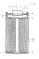
- FIG. 1 is a cross-sectional view of a secondary battery which is an example of the embodiment.
- the negative electrode for a secondary battery includes a negative electrode mixture containing a negative electrode active material, an additive, and a conductive agent, the negative electrode active material contains a Si-containing material, and the additive is an alkali.
- the conductive agent contains a metal sulfate, the conductive agent contains carbon nanotubes, and the content of the alkali metal sulfate in the negative electrode mixture is 0.0025% by mass or more, 0, based on the total amount of the negative electrode active material. .1 mass% or less.
- the content of the alkali metal sulfate in the negative electrode mixture needs to be within the above range.
- the content of the alkali metal sulfate is less than 0.0025% by mass with respect to the total amount of the negative electrode active material, for example, the reaction between the carbon nanotubes and the electrolytic solution cannot be sufficiently suppressed, and the initial charge / discharge efficiency.
- the effect of suppressing the decrease in the amount of When the content of the alkali metal sulfate exceeds 0.1% by mass with respect to the total amount of the negative electrode active material, for example, a large amount of the alkali metal sulfate is present in a place other than the carbon nanotube, and the alkali metal sulfate is present.
- the influence of the side reaction derived from the salt becomes large, and the effect of suppressing the decrease in the initial charge / discharge efficiency cannot be obtained.
- the carbon nanotubes contained in the negative electrode mixture follow the expansion and contraction of the Si-containing material due to charging and discharging, the increase of the Si-containing material isolated from the conductive path in the negative electrode mixture is suppressed. Therefore, the carbon nanotubes contribute to the effect of suppressing a decrease in the conductivity of the negative electrode due to expansion and contraction of the Si-containing material and suppressing a decrease in charge / discharge cycle characteristics.
- number (1) to numerical value (2) means a numerical value (1) or more and a numerical value (2) or less.
- FIG. 1 is a cross-sectional view of a secondary battery which is an example of the embodiment.
- the secondary battery 10 shown in FIG. 1 has a wound electrode body 14 in which a positive electrode 11 and a negative electrode 12 are wound via a separator 13, a non-aqueous electrolyte, and arranged above and below the electrode body 14, respectively.
- the insulating plates 18 and 19 and a battery case 15 for accommodating the above members are provided.
- the battery case 15 is composed of a bottomed cylindrical case body 16 and a sealing body 17 that closes an opening of the case body 16.
- the winding type electrode body 14 instead of the winding type electrode body 14, another form of an electrode body such as a laminated type electrode body in which positive electrodes and negative electrodes are alternately laminated via a separator may be applied.
- examples of the battery case 15 include a metal case such as a cylinder, a square, a coin, and a button, and a resin case (laminated battery) formed by laminating a resin sheet
- the case body 16 is, for example, a bottomed cylindrical metal container.
- a gasket 28 is provided between the case body 16 and the sealing body 17 to ensure the airtightness inside the battery.
- the case body 16 has, for example, an overhanging portion 22 that supports the sealing body 17 with a part of the side surface overhanging inward.
- the overhanging portion 22 is preferably formed in an annular shape along the circumferential direction of the case body 16, and the sealing body 17 is supported on the upper surface thereof.
- the sealing body 17 has a structure in which a filter 23, a lower valve body 24, an insulating member 25, an upper valve body 26, and a cap 27 are laminated in this order from the electrode body 14 side.
- Each member constituting the sealing body 17 has, for example, a disk shape or a ring shape, and each member except the insulating member 25 is electrically connected to each other.
- the lower valve body 24 and the upper valve body 26 are connected to each other at the central portion thereof, and an insulating member 25 is interposed between the peripheral portions thereof.
- the lower valve body 24 deforms and breaks so as to push the upper valve body 26 toward the cap 27 side, and the lower valve body 24 and the upper valve body 26 The current path between them is cut off.
- the upper valve body 26 breaks and gas is discharged from the opening of the cap 27.
- the positive electrode lead 20 attached to the positive electrode 11 extends to the sealing body 17 side through the through hole of the insulating plate 18, and the negative electrode lead 21 attached to the negative electrode 12 is the insulating plate 19. It extends to the bottom side of the case body 16 through the outside.
- the positive electrode lead 20 is connected to the lower surface of the filter 23, which is the bottom plate of the sealing body 17, by welding or the like, and the cap 27, which is the top plate of the sealing body 17 electrically connected to the filter 23, serves as the positive electrode terminal.
- the negative electrode lead 21 is connected to the inner surface of the bottom of the case body 16 by welding or the like, and the case body 16 serves as a negative electrode terminal.
- the positive electrode 11, the negative electrode 12, the separator 13, and the non-aqueous electrolyte constituting the secondary battery 10 will be described in detail.
- the positive electrode 11 includes, for example, a positive electrode current collector and a positive electrode mixture layer formed on the positive electrode current collector.
- a positive electrode current collector a metal foil stable in the potential range of the positive electrode such as aluminum or an aluminum alloy, a film in which the metal is arranged on the surface layer, or the like can be used.
- the positive electrode mixture layer is composed of, for example, a positive electrode mixture containing a positive electrode active material, a binder, a conductive agent, and the like.
- the positive electrode mixture layer is preferably formed on both sides of the positive electrode current collector.
- a slurry of a positive electrode mixture containing a positive electrode active material, a binder, a conductive agent, etc. is applied onto the positive electrode current collector, the coating film is dried and rolled, and the positive electrode mixture layer is collected as a positive electrode. It can be manufactured by forming it on both sides of an electric body.
- a lithium transition metal composite oxide or the like is used as the positive electrode active material.
- Metal elements contained in the lithium transition metal composite oxide include Ni, Co, Mn, Al, B, Mg, Ti, V, Cr, Fe, Cu, Zn, Ga, Sr, Zr, Nb, In and Sn. , Ta, W and the like. Above all, it is preferable to contain at least one of Ni, Co and Mn.
- suitable composite oxides include lithium transition metal composite oxides containing Ni, Co and Mn, and lithium transition metal composite oxides containing Ni, Co and Al.
- Examples of the conductive agent contained in the positive electrode mixture layer include carbon materials such as carbon black, acetylene black, ketjen black, graphene, carbon nanotubes, and graphite.
- Examples of the binder contained in the positive electrode mixture layer include fluororesins such as polytetrafluoroethylene (PTFE) and polyvinylidene fluoride (PVDF), polyacrylonitrile (PAN), polyimides, acrylic resins, polyolefins, and carboxymethyl cellulose (CMC). Alternatively, its salt, polyethylene oxide (PEO) and the like can be mentioned.
- the negative electrode 12 includes, for example, a negative electrode current collector and a negative electrode mixture layer formed on the current collector.
- a negative electrode current collector for example, a foil of a metal stable in the potential range of the negative electrode such as copper or a copper alloy, a film in which the metal is arranged on the surface layer, or the like can be used.
- the negative electrode mixture layer is composed of a negative electrode mixture containing a negative electrode active material, an additive, a conductive agent, and the like.
- the negative electrode mixture preferably contains a binder in addition to the above substances.
- a slurry of a negative electrode mixture containing a negative electrode active material, an additive, a conductive agent, a binder, and the like is applied to a negative electrode current collector, and the coating film is dried and rolled to form a negative electrode mixture layer. It can be manufactured by forming it on both sides of the negative electrode current collector.
- the negative electrode active material contains a Si-containing material.
- the Si-containing material may be any material that can occlude and release lithium ions, but from the viewpoint of increasing the capacity of the secondary battery, the lithium ion conductive phase, the Si particles dispersed in the lithium ion conductive phase, and the Si particles.
- the lithium ion conductive phase is preferably a Si-containing material which is at least one selected from a silicon oxide phase, a silicate phase and a carbon phase.
- the silicate phase is, for example, at least one element E1 selected from lithium, sodium, potassium, rubidium, cesium, francium, beryllium, magnesium, calcium, strontium, barium, and radium because of its high lithium ion conductivity. Is preferably included.
- the silicate phase further includes zirconium, niobium, tantalum, lanthanum, vanadium, titanium, phosphorus, bismuth, zinc, tin, lead, antimony, cobalt, and fluorine in terms of suppressing a decrease in initial charge / discharge efficiency.
- Tungsten, aluminum, and boron preferably containing at least one element E2.
- a conductive film made of a highly conductive material is formed on the particle surface of the Si-containing material.
- the constituent material of the conductive coating include at least one selected from a carbon material, a metal, and a metal compound. Of these, a carbon material such as amorphous carbon is preferable.
- the carbon film can be formed by, for example, a CVD method using acetylene, methane or the like, a method of mixing coal pitch, petroleum pitch, phenol resin or the like with a silicon-based active material and performing heat treatment. Further, a conductive film may be formed by fixing a conductive filler such as carbon black to the particle surface of the Si-containing material using a binder.
- the Si-containing material examples include a composite material A containing Si particles dispersed in a silicate phase and a silicate phase, a composite material B containing silicon oxide phase and Si particles dispersed in a silicon oxide phase, a carbon phase, and the like.
- a composite material C containing Si particles dispersed in a carbon phase examples include a composite material C containing Si particles dispersed in a carbon phase. These may be used alone or in combination of two or more.
- the silicate phase of the composite material A preferably contains the above-mentioned element E1, and more preferably further contains the above-mentioned element E2.
- a silicate phase containing lithium (hereinafter, may be referred to as a lithium silicate phase) is preferable from the viewpoints of high lithium ion conductivity and suppression of a decrease in initial charge / discharge efficiency.
- the composite material A preferably contains a lithium silicate phase and Si particles dispersed in the lithium silicate phase (hereinafter, may be referred to as LSX).
- the content of the silicon particles in the composite material A is preferably 30% by mass or more and 80% by mass or less, preferably 35% by mass or more and 75% by mass, in terms of increasing the capacity and improving the charge / discharge cycle characteristics. It is preferably 55% by mass or more, and more preferably 70% by mass or less.
- the content of silicon particles can be measured by Si-NMR.
- the desirable measurement conditions for Si-NMR are shown below.
- Measuring device Solid-state nuclear magnetic resonance spectrum measuring device (INOVA-400) manufactured by Varian Probe: Varian 7mm CPMAS-2 MAS: 4.2kHz MAS speed: 4kHz Pulse: DD (45 ° pulse + signal capture time 1H decouple) Repeat time: 1200 sec Observation width: 100 kHz Observation center: Around -100ppm Signal capture time: 0.05sec Accumulation number: 560 Sample amount: 207.6 mg
- the Si particles dispersed in the silicate phase have a particle-like phase of Si alone, and are composed of a single crystallite or a plurality of crystallites.
- the crystallite size of the Si particles is preferably 30 nm or less, for example, in terms of improving charge / discharge cycle characteristics.
- the lower limit of the crystallite size of the Si particles is not particularly limited, but is, for example, 5 nm.
- the crystallite size of the Si particles is more preferably 10 nm or more and 30 nm or less, and further preferably 15 nm or more and 25 nm or less.
- the crystallite size of the Si particles is calculated by Scherrer's equation from the half width of the diffraction peak attributed to the Si (111) plane of the X-ray diffraction (XRD) pattern of the Si particles.
- the average particle size of the Si particles is preferably 500 nm or less, more preferably 200 nm or less, and even more preferably 50 nm or less before the initial charging, for example, from the viewpoint of suppressing cracks in the Si particles themselves.
- the average particle size of the Si particles is preferably 400 nm or less, more preferably 100 nm or less.
- the average particle size of Si particles is measured by observing a cross-sectional SEM (scanning electron microscope) photograph of composite material A. Specifically, the average particle size of the Si particles is obtained by averaging the maximum diameters of any 100 Si particles.
- the composite material B in which Si particles are dispersed in the silicon oxide phase is represented by, for example, the general formula SiO x (preferably in the range of 0 ⁇ x ⁇ 2, more preferably in the range of 0.5 ⁇ x ⁇ 1.6). Will be done.
- the composite material C in which Si particles are dispersed in the carbon phase is, for example, the general formula SixC1y (preferably in the range of 0 ⁇ x ⁇ 1 and 0 ⁇ y ⁇ 1, 0.3 ⁇ x ⁇ 0.45 and 0.7 ⁇ 0.7 ⁇ . The range of y ⁇ 0.55 is more preferable).
- the Si particle content, crystallite size, and average particle size of the composite materials B and C may be the same as those of the composite material A.
- the content of the Si-containing material in the negative electrode active material is, for example, 1% by mass or more with respect to the total amount of the negative electrode active material in terms of suppressing the increase in capacity of the secondary battery and the deterioration of charge / discharge cycle characteristics. , 15% by mass or less is preferable.
- the negative electrode active material preferably further contains a carbon material that electrochemically occludes and releases lithium ions as another negative electrode material having a smaller degree of expansion and contraction during charging and discharging than a Si-containing material.
- the content of the carbon material in the negative electrode active material is 85% by mass or more and 99% by mass or less with respect to the total amount of the negative electrode active material in terms of suppressing deterioration of charge / discharge cycle characteristics of the secondary battery, for example. Is preferable.
- Examples of the carbon material include graphite, easily graphitized carbon (soft carbon), and non-graphitized carbon (hard carbon). Among them, graphite having excellent charge / discharge stability and a small irreversible capacity is preferable.
- Graphite means a material having a graphite-type crystal structure, and examples thereof include natural graphite, artificial graphite, and graphitized mesophase carbon particles.
- the content of the negative electrode active material in the negative electrode mixture is, for example, preferably 85% by mass or more, more preferably 90% by mass or more, and 95% by mass or more, based on the total amount of the negative electrode mixture. More preferably.
- Examples of carbon nanotubes as conductive agents contained in the negative electrode mixture include single-walled carbon nanotubes, double-walled carbon nanotubes, and multi-walled carbon nanotubes.
- Single-walled carbon nanotubes are carbon nanostructures in which one layer of graphene sheets constitutes one cylindrical shape, and two-walled carbon nanotubes are two layers of graphene sheets laminated concentrically.
- the multi-walled carbon nanotube is a carbon nanostructure that constitutes one cylindrical shape by concentrically laminating three or more layers of graphene sheets in a concentric manner.
- the graphene sheet refers to a layer in which the carbon atom of the sp2 hybrid orbital constituting the graphite crystal is located at the apex of the regular hexagon.
- the shape of carbon nanotubes is not limited. Such shapes include various forms including needle shape, cylindrical tube shape, fish bone shape (fishbone or cup laminated type), playing card shape (platelet) and coil shape.
- the fiber length of carbon nanotubes is preferably 500 nm or more and 200 ⁇ m or less, and preferably 1 ⁇ m or more and 100 ⁇ m or less, for example, in terms of suppressing deterioration of charge / discharge cycle characteristics.
- the fiber length of carbon nanotubes can be determined by measuring the length of 50 arbitrary carbon nanotubes with a field emission scanning microscope (FE-SEM) and arithmetically averaging them.
- the outermost peripheral diameter (that is, the fiber diameter) of the carbon nanotube is preferably 0.5 nm or more and 20 nm or less, and is 1 nm or more and 10 nm or less, for example, from the viewpoint of suppressing deterioration of charge / discharge cycle characteristics. Is more preferable.
- the outermost diameter of the carbon nanotubes can be determined by measuring the outer diameters of 50 arbitrary carbon nanotubes with a field emission scanning microscope (FE-SEM) or a transmission electron microscope (TEM) and calculating by arithmetic averaging.
- the content of carbon nanotubes in the negative electrode mixture is 0.01% by mass or more and 1.0% by mass or less with respect to the total amount of the negative electrode active material in terms of suppressing deterioration of charge / discharge cycle characteristics, for example. It is preferably 0.1% by mass or more and 0.8% by mass or less.
- the conductive agent contained in the negative electrode mixture may contain a particulate conductive agent in addition to the carbon nanotubes.
- the particulate conductive agent include carbon materials such as carbon black, acetylene black, ketjen black, and graphite.
- its primary particle size is preferably 5 nm or more and 100 nm or less, and the aspect ratio is preferably less than 10.
- alkali metal sulfate examples include lithium sulfate, sodium sulfate, potassium sulfate, rubidium sulfate, cesium sulfate, and francium sulfate.
- the alkali metal sulfate may contain at least one selected from lithium sulfate, sodium sulfate, and potassium sulfate in terms of further suppressing a decrease in the initial charge / discharge efficiency of the secondary battery. preferable.
- the content of the alkali metal sulfate in the negative electrode mixture is 0.0025% by mass or more, 0.1, based on the total amount of the negative electrode active material, in that it suppresses a decrease in the initial charge / discharge efficiency of the secondary battery. It may be 10% by mass or less, but preferably 0.01% by mass or more and 0.1% by mass or less, and more preferably 0.02% by mass or more and 0.08% by mass or less.
- the binder contained in the negative electrode mixture may be the same as the binder used in the positive electrode 11.
- the content of the binder in the negative electrode mixture is, for example, preferably 0.5% by mass to 10% by mass, more preferably 1% by mass to 5% by mass, based on the total amount of the negative electrode active material.
- a porous sheet having ion permeability and insulating property is used as the separator 13.
- the porous sheet include a microporous thin film, a woven fabric, and a non-woven fabric.
- olefin resin such as polyethylene, polypropylene, a copolymer containing at least one of ethylene and propylene, cellulose and the like are suitable.
- the separator 13 may have either a single-layer structure or a laminated structure. A heat-resistant layer or the like may be formed on the surface of the separator 13.
- the non-aqueous electrolyte contains a non-aqueous solvent and an electrolyte salt.
- the non-aqueous electrolyte is not limited to the liquid electrolyte, and may be a solid electrolyte using a gel polymer or the like.
- the electrolyte salt for example, lithium salts such as LiFSI, LiTFSI, LiBF 4 , LiPF 6 and the like are used.
- the solvent include ethylene carbonate (EC), propylene carbonate (PC), dimethyl carbonate (DMC), ethyl methyl carbonate (EMC), diethyl carbonate (DEC), methyl acetate (MA), methyl propionate (MP) and the like.
- the non-aqueous solvent may contain a halogen substituent in which at least a part of hydrogen in these solvents is replaced with a halogen atom such as fluorine.
- halogen substituent examples include a fluorinated cyclic carbonate such as fluoroethylene carbonate (FEC), a fluorinated chain carbonate, and a fluorinated chain carboxylic acid ester such as methyl fluoropropionate (FMP).
- FEC fluoroethylene carbonate
- FMP fluorinated chain carboxylic acid ester
- Example 1 [Adjustment of Si-containing material (LSX)] Silicon dioxide and lithium carbonate are mixed so that the atomic ratio Si / Li is 1.05, and the mixture is calcined in air at 950 ° C. for 10 hours. Lithium represented by the formula: Li 2 Si 2 O 5 I got a silicate. The obtained lithium silicate was pulverized so as to have an average particle size of 10 ⁇ m.
- the above lithium silicate and the raw material silicon were mixed at a mass ratio of 70:30.
- the mixture was ground at 200 rpm for 50 hours.
- the powdery mixture was taken out in the inert atmosphere and fired at 800 ° C. for 4 hours in the inert atmosphere under the pressure of a hot press to obtain a sintered body (LSX) of the mixture. rice field.
- the obtained LSX is pulverized and passed through a 40 ⁇ m mesh, the obtained LSX particles are mixed with coal pitch, the mixture is calcined at 800 ° C. in an inert atmosphere, and the surface of the LSX particles is made of conductive carbon. It was coated to form a conductive layer.
- the coating amount of the conductive layer was set to 5% by mass with respect to the total mass of the LSX particles and the conductive layer.
- LSX particles having a conductive layer and having an average particle size of 5 ⁇ m were obtained.
- the content of Li 2 Si 2 O 5 measured by Si-NMR was 70% by mass (the content of Si particles was 30% by mass).
- LSX particles having a conductive layer and graphite were mixed at a mass ratio of 5:95, and this mixture was used as a negative electrode active material.
- Negative electrode active material, sodium sulfate (additive), carbon nanotube (conductive agent), sodium carboxymethyl cellulose, and styrene-butadiene rubber were added in an amount of 100: 0.0025: 0.3: 1.3: 1.0.
- the mixture was mixed by mass ratio, and an appropriate amount of water was added to prepare a slurry of the negative electrode mixture.
- the slurry of the negative electrode mixture is applied to both sides of the negative electrode current collector made of copper foil, the coating film is dried, and then the coating film is rolled using a roller to combine the negative electrodes on both sides of the negative electrode current collector.
- a negative electrode on which the agent layer was formed was prepared.
- Non-aqueous electrolyte LiPF 6 is dissolved at a ratio of 1.2 mol / L in a mixed solvent in which ethylene carbonate (EC), dimethyl carbonate (DMC), and methyl acetate (MA) are mixed at a volume ratio of 20:40:40. To prepare a non-aqueous electrolyte solution.
- EC ethylene carbonate
- DMC dimethyl carbonate
- MA methyl acetate
- Test cell The positive electrode and the negative electrode were laminated so as to face each other via a separator and wound around the same to prepare an electrode body. Next, the electrode body and the non-aqueous electrolyte solution are housed in a bottomed cylindrical battery case body, the electrolyte solution is injected, and then the opening of the battery case body is sealed with a gasket and a sealing body to form a test cell. Made.
- Example 2 In the production of the negative electrode, the negative electrode active material, sodium sulfate (additive), carbon nanotube (conductive agent), sodium carboxymethyl cellulose, and styrene butadiene rubber are used as 100: 0.025: 0.3: 1.3. A test cell was prepared in the same manner as in Example 1 except that the mixture was mixed at a mass ratio of 1: 1.0.
- Example 3 In the production of the negative electrode, the negative electrode active material, sodium sulfate (additive), carbon nanotube (conductive agent), sodium carboxymethyl cellulose, and styrene-butadiene rubber are mixed with 100: 0.05: 0.3: 1.3. A test cell was prepared in the same manner as in Example 1 except that the mixture was mixed at a mass ratio of 1: 1.0.
- Example 4 In the production of the negative electrode, the negative electrode active material, sodium sulfate (additive), carbon nanotube (conducting agent), sodium carboxymethyl cellulose, and styrene-butadiene rubber are used as 100: 0.1: 0.3: 1.3. A test cell was prepared in the same manner as in Example 1 except that the mixture was mixed at a mass ratio of 1: 1.0.
- the negative electrode active material sodium sulfate (additive), carbon nanotube (conducting agent), sodium carboxymethyl cellulose, and styrene-butadiene rubber are used as 100: 0.3: 0.3: 1.3.
- a test cell was prepared in the same manner as in Example 1 except that the mixture was mixed at a mass ratio of 1: 1.0.
- First charge / discharge efficiency (first discharge capacity / first charge capacity) x 100
- Table 1 shows the evaluation results of the initial charge / discharge efficiency in each Example and Comparative Example. However, the evaluation results in Table 1 are based on the initial charge / discharge efficiency of Comparative Example 1, and the initial charge / discharge efficiencies of the other Examples and Comparative Examples are shown by the rate of increase with respect to the above criteria. When the rate of increase is positive, it indicates that the decrease in the initial charge / discharge efficiency is suppressed.
Landscapes
- Chemical & Material Sciences (AREA)
- Chemical Kinetics & Catalysis (AREA)
- Electrochemistry (AREA)
- General Chemical & Material Sciences (AREA)
- Engineering & Computer Science (AREA)
- Inorganic Chemistry (AREA)
- Composite Materials (AREA)
- Manufacturing & Machinery (AREA)
- Materials Engineering (AREA)
- Physics & Mathematics (AREA)
- Condensed Matter Physics & Semiconductors (AREA)
- General Physics & Mathematics (AREA)
- Crystallography & Structural Chemistry (AREA)
- Battery Electrode And Active Subsutance (AREA)
Abstract
This negative electrode for secondary batteries is provided with a negative electrode mixture that contains a negative electrode active material, an additive and a conductive agent. The negative electrode active material contains an Si-containing material; the additive contains an alkali metal sulfate salt; and the conductive agent contains carbon nanotubes. The content of the alkali metal sulfate salt in the negative electrode mixture is from 0.0025% by mass to 0.1% by mass relative to the total mass of the negative electrode active material.
Description
本開示は、二次電池用負極および二次電池に関する。
This disclosure relates to a negative electrode for a secondary battery and a secondary battery.
Si含有材料は、リチウムと合金化する合金化材料であり、黒鉛などの炭素系活物質と比べて単位体積当りに多くのリチウムイオンを吸蔵できることが知られており、二次電池の負極活物質への利用が期待されている。
The Si-containing material is an alloying material that alloys with lithium, and is known to be able to occlude more lithium ions per unit volume than carbon-based active materials such as graphite, and is a negative electrode active material for secondary batteries. It is expected to be used for.
しかし、Si含有材料は、充放電時の体積変化(膨張・収縮)が大きいため、負極の導電性が低下し易く、その結果、充放電サイクル特性が低下するという問題がある。
However, since the Si-containing material has a large volume change (expansion / contraction) during charge / discharge, the conductivity of the negative electrode tends to decrease, and as a result, there is a problem that the charge / discharge cycle characteristics decrease.
このような問題点を改善すべく、Si含有材料を有する負極内にカーボンナノチューブを添加して、Si含有剤の膨張・収縮に伴う負極の導電性低下を抑え、充放電サイクル特性の低下を抑制する技術がある。
In order to improve such problems, carbon nanotubes are added into the negative electrode having a Si-containing material to suppress the decrease in conductivity of the negative electrode due to expansion and contraction of the Si-containing agent and suppress the decrease in charge / discharge cycle characteristics. There is a technique to do.
カーボンナノチューブは比表面積が大きいため、二次電池の初回充放電の際に電解液と反応して、初回の充放電効率が低下するといった問題がある。なお、初回の充放電効率とは、初回の充電容量に対する初回の放電容量の割合である。
Since carbon nanotubes have a large specific surface area, there is a problem that the initial charge / discharge efficiency decreases due to reaction with the electrolytic solution during the initial charge / discharge of the secondary battery. The initial charge / discharge efficiency is the ratio of the initial discharge capacity to the initial charge capacity.
本開示の一態様である二次電池用負極は、負極活物質と、添加剤と、導電剤とを含む負極合剤を備え、前記負極活物質はSi含有材料を含み、前記添加剤はアルカリ金属硫酸塩を含み、前記導電剤は、カーボンナノチューブを含み、前記負極合剤中の前記アルカリ金属硫酸塩の含有量は、前記負極活物質の総量に対して、0.0025質量%以上、0.1質量%以下である。
The negative electrode for a secondary battery according to one aspect of the present disclosure includes a negative electrode mixture containing a negative electrode active material, an additive, and a conductive agent, the negative electrode active material contains a Si-containing material, and the additive is an alkali. The conductive agent contains a metal sulfate, the conductive agent contains carbon nanotubes, and the content of the alkali metal sulfate in the negative electrode mixture is 0.0025% by mass or more, 0, based on the total amount of the negative electrode active material. .1 mass% or less.
本開示の一態様である二次電池は、上記二次電池用負極と、正極と、非水電解液と、を備える。
The secondary battery according to one aspect of the present disclosure includes the negative electrode for the secondary battery, the positive electrode, and the non-aqueous electrolytic solution.
本開示によれば、初回の充放電効率の低下を抑制することが可能となる。
According to the present disclosure, it is possible to suppress a decrease in the initial charge / discharge efficiency.
本開示の一態様である二次電池用負極は、負極活物質と、添加剤と、導電剤とを含む負極合剤を備え、前記負極活物質はSi含有材料を含み、前記添加剤はアルカリ金属硫酸塩を含み、前記導電剤は、カーボンナノチューブを含み、前記負極合剤中の前記アルカリ金属硫酸塩の含有量は、前記負極活物質の総量に対して、0.0025質量%以上、0.1質量%以下である。本開示によれば、アルカリ金属硫酸塩は特異的にカーボンナノチューブ上に多く存在して、カーボンナノチューブと電解液との反応を抑制する性質を有しているため、二次電池における初回の充放電効率の低下が抑制されると考えられる。但し、上記効果を奏するには、負極合剤中のアルカリ金属硫酸塩の含有量を上記範囲とする必要がある。アルカリ金属硫酸塩の含有量が負極活物質の総量に対して、0.0025質量%未満の場合には、例えば、カーボンナノチューブと電解液との反応を十分に抑えられず、初回の充放電効率の低下を抑制する効果が得られない。また、アルカリ金属硫酸塩の含有量が負極活物質の総量に対して、0.1質量%を超える場合には、例えば、アルカリ金属硫酸塩がカーボンナノチューブ以外の箇所に多く存在し、アルカリ金属硫酸塩に由来する副反応の影響が大きくなり、初回の充放電効率の低下を抑制する効果が得られない。
The negative electrode for a secondary battery according to one aspect of the present disclosure includes a negative electrode mixture containing a negative electrode active material, an additive, and a conductive agent, the negative electrode active material contains a Si-containing material, and the additive is an alkali. The conductive agent contains a metal sulfate, the conductive agent contains carbon nanotubes, and the content of the alkali metal sulfate in the negative electrode mixture is 0.0025% by mass or more, 0, based on the total amount of the negative electrode active material. .1 mass% or less. According to the present disclosure, since a large amount of alkali metal sulfate is specifically present on carbon nanotubes and has a property of suppressing the reaction between carbon nanotubes and an electrolytic solution, the first charge / discharge in a secondary battery It is considered that the decrease in efficiency is suppressed. However, in order to obtain the above effect, the content of the alkali metal sulfate in the negative electrode mixture needs to be within the above range. When the content of the alkali metal sulfate is less than 0.0025% by mass with respect to the total amount of the negative electrode active material, for example, the reaction between the carbon nanotubes and the electrolytic solution cannot be sufficiently suppressed, and the initial charge / discharge efficiency. The effect of suppressing the decrease in the amount of When the content of the alkali metal sulfate exceeds 0.1% by mass with respect to the total amount of the negative electrode active material, for example, a large amount of the alkali metal sulfate is present in a place other than the carbon nanotube, and the alkali metal sulfate is present. The influence of the side reaction derived from the salt becomes large, and the effect of suppressing the decrease in the initial charge / discharge efficiency cannot be obtained.
なお、負極合剤中に含まれるカーボンナノチューブは、充放電に伴うSi含有材料の膨張・収縮に追従するため、負極合剤中の導電パスから孤立するSi含有材料の増加が抑制される。したがって、カーボンナノチューブは、Si含有材料の膨張・収縮に伴う負極の導電性低下を抑え、充放電サイクル特性の低下を抑制する効果に寄与している。
Since the carbon nanotubes contained in the negative electrode mixture follow the expansion and contraction of the Si-containing material due to charging and discharging, the increase of the Si-containing material isolated from the conductive path in the negative electrode mixture is suppressed. Therefore, the carbon nanotubes contribute to the effect of suppressing a decrease in the conductivity of the negative electrode due to expansion and contraction of the Si-containing material and suppressing a decrease in charge / discharge cycle characteristics.
以下、図面を参照しながら、本開示に係る二次電池用負極および二次電池の実施形態について詳説する。なお、本明細書において、「数値(1)~数値(2)」との記載は、数値(1)以上、数値(2)以下を意味する。
Hereinafter, embodiments of the negative electrode for a secondary battery and the secondary battery according to the present disclosure will be described in detail with reference to the drawings. In this specification, the description of "numerical value (1) to numerical value (2)" means a numerical value (1) or more and a numerical value (2) or less.
図1は、実施形態の一例である二次電池の断面図である。図1に示す二次電池10は、正極11及び負極12がセパレータ13を介して巻回されてなる巻回型の電極体14と、非水電解質と、電極体14の上下にそれぞれ配置された絶縁板18,19と、上記部材を収容する電池ケース15と、を備える。電池ケース15は、有底円筒形状のケース本体16と、ケース本体16の開口部を塞ぐ封口体17とにより構成される。なお、巻回型の電極体14の代わりに、正極及び負極がセパレータを介して交互に積層されてなる積層型の電極体など、他の形態の電極体が適用されてもよい。また、電池ケース15としては、円筒形、角形、コイン形、ボタン形等の金属製ケース、樹脂シートをラミネートして形成された樹脂製ケース(ラミネート型電池)などが例示できる。
FIG. 1 is a cross-sectional view of a secondary battery which is an example of the embodiment. The secondary battery 10 shown in FIG. 1 has a wound electrode body 14 in which a positive electrode 11 and a negative electrode 12 are wound via a separator 13, a non-aqueous electrolyte, and arranged above and below the electrode body 14, respectively. The insulating plates 18 and 19 and a battery case 15 for accommodating the above members are provided. The battery case 15 is composed of a bottomed cylindrical case body 16 and a sealing body 17 that closes an opening of the case body 16. In addition, instead of the winding type electrode body 14, another form of an electrode body such as a laminated type electrode body in which positive electrodes and negative electrodes are alternately laminated via a separator may be applied. Further, examples of the battery case 15 include a metal case such as a cylinder, a square, a coin, and a button, and a resin case (laminated battery) formed by laminating a resin sheet.
ケース本体16は、例えば有底円筒形状の金属製容器である。ケース本体16と封口体17との間にはガスケット28が設けられ、電池内部の密閉性が確保される。ケース本体16は、例えば側面部の一部が内側に張出した、封口体17を支持する張り出し部22を有する。張り出し部22は、ケース本体16の周方向に沿って環状に形成されることが好ましく、その上面で封口体17を支持する。
The case body 16 is, for example, a bottomed cylindrical metal container. A gasket 28 is provided between the case body 16 and the sealing body 17 to ensure the airtightness inside the battery. The case body 16 has, for example, an overhanging portion 22 that supports the sealing body 17 with a part of the side surface overhanging inward. The overhanging portion 22 is preferably formed in an annular shape along the circumferential direction of the case body 16, and the sealing body 17 is supported on the upper surface thereof.
封口体17は、電極体14側から順に、フィルタ23、下弁体24、絶縁部材25、上弁体26、及びキャップ27が積層された構造を有する。封口体17を構成する各部材は、例えば円板形状又はリング形状を有し、絶縁部材25を除く各部材は互いに電気的に接続されている。下弁体24と上弁体26は各々の中央部で互いに接続され、各々の周縁部の間には絶縁部材25が介在している。内部短絡等による発熱で二次電池10の内圧が上昇すると、例えば下弁体24が上弁体26をキャップ27側に押し上げるように変形して破断し、下弁体24と上弁体26の間の電流経路が遮断される。さらに内圧が上昇すると、上弁体26が破断し、キャップ27の開口部からガスが排出される。
The sealing body 17 has a structure in which a filter 23, a lower valve body 24, an insulating member 25, an upper valve body 26, and a cap 27 are laminated in this order from the electrode body 14 side. Each member constituting the sealing body 17 has, for example, a disk shape or a ring shape, and each member except the insulating member 25 is electrically connected to each other. The lower valve body 24 and the upper valve body 26 are connected to each other at the central portion thereof, and an insulating member 25 is interposed between the peripheral portions thereof. When the internal pressure of the secondary battery 10 rises due to heat generated by an internal short circuit or the like, for example, the lower valve body 24 deforms and breaks so as to push the upper valve body 26 toward the cap 27 side, and the lower valve body 24 and the upper valve body 26 The current path between them is cut off. When the internal pressure further rises, the upper valve body 26 breaks and gas is discharged from the opening of the cap 27.
図1に示す二次電池10では、正極11に取り付けられた正極リード20が絶縁板18の貫通孔を通って封口体17側に延び、負極12に取り付けられた負極リード21が絶縁板19の外側を通ってケース本体16の底部側に延びている。正極リード20は封口体17の底板であるフィルタ23の下面に溶接等で接続され、フィルタ23と電気的に接続された封口体17の天板であるキャップ27が正極端子となる。負極リード21はケース本体16の底部内面に溶接等で接続され、ケース本体16が負極端子となる。
In the secondary battery 10 shown in FIG. 1, the positive electrode lead 20 attached to the positive electrode 11 extends to the sealing body 17 side through the through hole of the insulating plate 18, and the negative electrode lead 21 attached to the negative electrode 12 is the insulating plate 19. It extends to the bottom side of the case body 16 through the outside. The positive electrode lead 20 is connected to the lower surface of the filter 23, which is the bottom plate of the sealing body 17, by welding or the like, and the cap 27, which is the top plate of the sealing body 17 electrically connected to the filter 23, serves as the positive electrode terminal. The negative electrode lead 21 is connected to the inner surface of the bottom of the case body 16 by welding or the like, and the case body 16 serves as a negative electrode terminal.
以下、二次電池10を構成する正極11、負極12、セパレータ13、非水電解質について詳述する。
Hereinafter, the positive electrode 11, the negative electrode 12, the separator 13, and the non-aqueous electrolyte constituting the secondary battery 10 will be described in detail.
[正極]
正極11は、例えば、正極集電体と、正極集電体上に形成された正極合剤層とを備える。正極集電体には、アルミニウム、アルミニウム合金などの正極の電位範囲で安定な金属の箔、当該金属を表層に配置したフィルム等を用いることができる。正極合剤層は、例えば、正極活物質、結着剤、導電剤等を含む正極合剤を含んで構成される。正極合剤層は、正極集電体の両面に形成されることが好ましい。正極11は、例えば、正極活物質、結着剤、導電剤等を含む正極合剤のスラリーを正極集電体上に塗布し、塗膜を乾燥、圧延して、正極合剤層を正極集電体の両面に形成することにより製造できる。 [Positive electrode]
Thepositive electrode 11 includes, for example, a positive electrode current collector and a positive electrode mixture layer formed on the positive electrode current collector. As the positive electrode current collector, a metal foil stable in the potential range of the positive electrode such as aluminum or an aluminum alloy, a film in which the metal is arranged on the surface layer, or the like can be used. The positive electrode mixture layer is composed of, for example, a positive electrode mixture containing a positive electrode active material, a binder, a conductive agent, and the like. The positive electrode mixture layer is preferably formed on both sides of the positive electrode current collector. For the positive electrode 11, for example, a slurry of a positive electrode mixture containing a positive electrode active material, a binder, a conductive agent, etc. is applied onto the positive electrode current collector, the coating film is dried and rolled, and the positive electrode mixture layer is collected as a positive electrode. It can be manufactured by forming it on both sides of an electric body.
正極11は、例えば、正極集電体と、正極集電体上に形成された正極合剤層とを備える。正極集電体には、アルミニウム、アルミニウム合金などの正極の電位範囲で安定な金属の箔、当該金属を表層に配置したフィルム等を用いることができる。正極合剤層は、例えば、正極活物質、結着剤、導電剤等を含む正極合剤を含んで構成される。正極合剤層は、正極集電体の両面に形成されることが好ましい。正極11は、例えば、正極活物質、結着剤、導電剤等を含む正極合剤のスラリーを正極集電体上に塗布し、塗膜を乾燥、圧延して、正極合剤層を正極集電体の両面に形成することにより製造できる。 [Positive electrode]
The
正極活物質は、例えば、リチウム遷移金属複合酸化物等が用いられる。リチウム遷移金属複合酸化物に含有される金属元素としては、Ni、Co、Mn、Al、B、Mg、Ti、V、Cr、Fe、Cu、Zn、Ga、Sr、Zr、Nb、In、Sn、Ta、W等が挙げられる。中でも、Ni、Co、Mnの少なくとも1種を含有することが好ましい。好適な複合酸化物の一例としては、Ni、Co、Mnを含有するリチウム遷移金属複合酸化物、Ni、Co、Alを含有するリチウム遷移金属複合酸化物が挙げられる。
As the positive electrode active material, for example, a lithium transition metal composite oxide or the like is used. Metal elements contained in the lithium transition metal composite oxide include Ni, Co, Mn, Al, B, Mg, Ti, V, Cr, Fe, Cu, Zn, Ga, Sr, Zr, Nb, In and Sn. , Ta, W and the like. Above all, it is preferable to contain at least one of Ni, Co and Mn. Examples of suitable composite oxides include lithium transition metal composite oxides containing Ni, Co and Mn, and lithium transition metal composite oxides containing Ni, Co and Al.
正極合剤層に含まれる導電剤としては、カーボンブラック、アセチレンブラック、ケッチェンブラック、グラフェン、カーボンナノチューブ、黒鉛等の炭素材料が例示できる。正極合剤層に含まれる結着剤としては、ポリテトラフルオロエチレン(PTFE)、ポリフッ化ビニリデン(PVDF)等のフッ素樹脂、ポリアクリロニトリル(PAN)、ポリイミド、アクリル樹脂、ポリオレフィン、カルボキシメチルセルロース(CMC)またはその塩、ポリエチレンオキシド(PEO)などが挙げられる。
Examples of the conductive agent contained in the positive electrode mixture layer include carbon materials such as carbon black, acetylene black, ketjen black, graphene, carbon nanotubes, and graphite. Examples of the binder contained in the positive electrode mixture layer include fluororesins such as polytetrafluoroethylene (PTFE) and polyvinylidene fluoride (PVDF), polyacrylonitrile (PAN), polyimides, acrylic resins, polyolefins, and carboxymethyl cellulose (CMC). Alternatively, its salt, polyethylene oxide (PEO) and the like can be mentioned.
[負極]
負極12は、例えば、負極集電体と、集電体上に形成された負極合剤層とを備える。負極集電体には、例えば、銅、銅合金などの負極の電位範囲で安定な金属の箔、当該金属を表層に配置したフィルム等を用いることができる。負極合剤層は、負極活物質、添加剤、導電剤等を含む負極合剤を含んで構成される。負極合剤は、上記物質の他に、結着剤を含むことが好適である。負極12は、例えば、負極活物質、添加剤、導電剤、結着剤等を含む負極合剤のスラリーを負極集電体に塗布し、塗膜を乾燥、圧延して、負極合剤層を負極集電体の両面に形成することにより製造できる。 [Negative electrode]
Thenegative electrode 12 includes, for example, a negative electrode current collector and a negative electrode mixture layer formed on the current collector. As the negative electrode current collector, for example, a foil of a metal stable in the potential range of the negative electrode such as copper or a copper alloy, a film in which the metal is arranged on the surface layer, or the like can be used. The negative electrode mixture layer is composed of a negative electrode mixture containing a negative electrode active material, an additive, a conductive agent, and the like. The negative electrode mixture preferably contains a binder in addition to the above substances. For the negative electrode 12, for example, a slurry of a negative electrode mixture containing a negative electrode active material, an additive, a conductive agent, a binder, and the like is applied to a negative electrode current collector, and the coating film is dried and rolled to form a negative electrode mixture layer. It can be manufactured by forming it on both sides of the negative electrode current collector.
負極12は、例えば、負極集電体と、集電体上に形成された負極合剤層とを備える。負極集電体には、例えば、銅、銅合金などの負極の電位範囲で安定な金属の箔、当該金属を表層に配置したフィルム等を用いることができる。負極合剤層は、負極活物質、添加剤、導電剤等を含む負極合剤を含んで構成される。負極合剤は、上記物質の他に、結着剤を含むことが好適である。負極12は、例えば、負極活物質、添加剤、導電剤、結着剤等を含む負極合剤のスラリーを負極集電体に塗布し、塗膜を乾燥、圧延して、負極合剤層を負極集電体の両面に形成することにより製造できる。 [Negative electrode]
The
負極活物質は、Si含有材料を含む。Si含有材料は、リチウムイオンを吸蔵・放出できる材料であればよいが、二次電池の高容量化等の観点から、リチウムイオン導電相と、リチウムイオン導電相に分散しているSi粒子と、を含み、リチウムイオン導電相は、ケイ素酸化物相、シリケート相及び炭素相から選択される少なくとも1種であるSi含有材料が好ましい。
The negative electrode active material contains a Si-containing material. The Si-containing material may be any material that can occlude and release lithium ions, but from the viewpoint of increasing the capacity of the secondary battery, the lithium ion conductive phase, the Si particles dispersed in the lithium ion conductive phase, and the Si particles. The lithium ion conductive phase is preferably a Si-containing material which is at least one selected from a silicon oxide phase, a silicate phase and a carbon phase.
シリケート相は、例えば、リチウムイオン伝導性が高い等の点から、リチウム、ナトリウム、カリウム、ルビジウム、セシウム、フランシウム、ベリリウム、マグネシウム、カルシウム、ストロンチウム、バリウム、ラジウムから選択される少なくとも1種の元素E1を含むことが好ましい。
The silicate phase is, for example, at least one element E1 selected from lithium, sodium, potassium, rubidium, cesium, francium, beryllium, magnesium, calcium, strontium, barium, and radium because of its high lithium ion conductivity. Is preferably included.
シリケート相は、例えば、初回の充放電効率の低下が抑えられる等の点から、さらに、ジルコニウム、ニオブ、タンタル、ランタン、バナジウム、チタン、リン、ビスマス、亜鉛、錫、鉛、アンチモン、コバルト、フッ素、タングステン、アルミニウム、ホウ素から選択される少なくとも1種の元素E2を含むことが好ましい。
The silicate phase further includes zirconium, niobium, tantalum, lanthanum, vanadium, titanium, phosphorus, bismuth, zinc, tin, lead, antimony, cobalt, and fluorine in terms of suppressing a decrease in initial charge / discharge efficiency. , Tungsten, aluminum, and boron, preferably containing at least one element E2.
Si含有材料の粒子表面には、導電性の高い材料で構成される導電被膜が形成されていることが好ましい。導電被膜の構成材料としては、炭素材料、金属、及び金属化合物から選択される少なくとも1種が例示できる。中でも、非晶質炭素等の炭素材料が好ましい。炭素被膜は、例えばアセチレン、メタン等を用いたCVD法、石炭ピッチ、石油ピッチ、フェノール樹脂等をシリコン系活物質と混合し、熱処理を行う方法などで形成できる。また、カーボンブラック等の導電フィラーを結着材を用いて、Si含有材料の粒子表面に固着させることで導電被膜を形成してもよい。
It is preferable that a conductive film made of a highly conductive material is formed on the particle surface of the Si-containing material. Examples of the constituent material of the conductive coating include at least one selected from a carbon material, a metal, and a metal compound. Of these, a carbon material such as amorphous carbon is preferable. The carbon film can be formed by, for example, a CVD method using acetylene, methane or the like, a method of mixing coal pitch, petroleum pitch, phenol resin or the like with a silicon-based active material and performing heat treatment. Further, a conductive film may be formed by fixing a conductive filler such as carbon black to the particle surface of the Si-containing material using a binder.
具体的なSi含有材料としては、シリケート相及びシリケート相に分散したSi粒子を含有する複合材料A、ケイ素酸化物相及びケイ素酸化物相に分散したSi粒子を含有する複合材料B、炭素相及び炭素相に分散したSi粒子を含有する複合材料C等が挙げられる。これらは、1種単独でも、2種以上を併用してもよい。
Specific examples of the Si-containing material include a composite material A containing Si particles dispersed in a silicate phase and a silicate phase, a composite material B containing silicon oxide phase and Si particles dispersed in a silicon oxide phase, a carbon phase, and the like. Examples thereof include a composite material C containing Si particles dispersed in a carbon phase. These may be used alone or in combination of two or more.
複合材料Aのシリケート相は、前述の元素E1を含むことが好ましく、前述の元素E2をさらに含むことがより好ましい。中でも、リチウムイオン伝導性が高い、初回の充放電効率の低下が抑えられる等の点から、リチウムを含むシリケート相(以下、リチウムシリケート相と称する場合がある)が好ましい。すなわち、複合材料Aは、リチウムシリケート相と、リチウムシリケート相内に分散しているSi粒子とを含むことが好ましい(以下、LSXと称する場合がある)。
The silicate phase of the composite material A preferably contains the above-mentioned element E1, and more preferably further contains the above-mentioned element E2. Among them, a silicate phase containing lithium (hereinafter, may be referred to as a lithium silicate phase) is preferable from the viewpoints of high lithium ion conductivity and suppression of a decrease in initial charge / discharge efficiency. That is, the composite material A preferably contains a lithium silicate phase and Si particles dispersed in the lithium silicate phase (hereinafter, may be referred to as LSX).
複合材料A中のシリコン粒子の含有量は、高容量化、充放電サイクル特性の向上等の点で、30質量%以上、80質量%以下であることが好ましく、35質量%以上、75質量%以下であることが好ましく、55質量%以上、70質量%以下であることがより好ましい。
The content of the silicon particles in the composite material A is preferably 30% by mass or more and 80% by mass or less, preferably 35% by mass or more and 75% by mass, in terms of increasing the capacity and improving the charge / discharge cycle characteristics. It is preferably 55% by mass or more, and more preferably 70% by mass or less.
シリコン粒子の含有量は、Si-NMRにより測定することができる。以下、Si-NMRの望ましい測定条件を示す。
The content of silicon particles can be measured by Si-NMR. The desirable measurement conditions for Si-NMR are shown below.
測定装置:バリアン社製、固体核磁気共鳴スペクトル測定装置(INOVA-400)
プローブ:Varian 7mm CPMAS-2
MAS:4.2kHz
MAS速度:4kHz
パルス:DD(45°パルス+シグナル取込時間1Hデカップル)
繰り返し時間:1200sec
観測幅:100kHz
観測中心:-100ppm付近
シグナル取込時間:0.05sec
積算回数:560
試料量:207.6mg
シリケート相内に分散しているSi粒子は、Si単体の粒子状の相を有し、単独または複数の結晶子で構成される。Si粒子の結晶子サイズは、例えば、充放電サイクル特性が向上する等の点で、30nm以下であることが好ましい。Si粒子の結晶子サイズの下限値は、特に限定されないが、例えば、5nmである。 Measuring device: Solid-state nuclear magnetic resonance spectrum measuring device (INOVA-400) manufactured by Varian
Probe: Varian 7mm CPMAS-2
MAS: 4.2kHz
MAS speed: 4kHz
Pulse: DD (45 ° pulse + signal capture time 1H decouple)
Repeat time: 1200 sec
Observation width: 100 kHz
Observation center: Around -100ppm Signal capture time: 0.05sec
Accumulation number: 560
Sample amount: 207.6 mg
The Si particles dispersed in the silicate phase have a particle-like phase of Si alone, and are composed of a single crystallite or a plurality of crystallites. The crystallite size of the Si particles is preferably 30 nm or less, for example, in terms of improving charge / discharge cycle characteristics. The lower limit of the crystallite size of the Si particles is not particularly limited, but is, for example, 5 nm.
また、Si粒子の結晶子サイズは、より好ましくは10nm以上、30nm以下であり、更に好ましくは15nm以上、25nm以下である。Si粒子の結晶子サイズは、Si粒子のX線回折(XRD)パターンのSi(111)面に帰属される回析ピークの半値幅からシェラーの式により算出される。
Further, the crystallite size of the Si particles is more preferably 10 nm or more and 30 nm or less, and further preferably 15 nm or more and 25 nm or less. The crystallite size of the Si particles is calculated by Scherrer's equation from the half width of the diffraction peak attributed to the Si (111) plane of the X-ray diffraction (XRD) pattern of the Si particles.
Si粒子の平均粒径は、例えば、Si粒子自身の亀裂を抑制する等の点から、初回充電前において、500nm以下が好ましく、200nm以下がより好ましく、50nm以下が更に好ましい。初回充電後においては、Si粒子の平均粒径は、400nm以下が好ましく、100nm以下がより好ましい。
The average particle size of the Si particles is preferably 500 nm or less, more preferably 200 nm or less, and even more preferably 50 nm or less before the initial charging, for example, from the viewpoint of suppressing cracks in the Si particles themselves. After the initial charging, the average particle size of the Si particles is preferably 400 nm or less, more preferably 100 nm or less.
Si粒子の平均粒径は、複合材料Aの断面SEM(走査型電子顕微鏡)写真を観察することにより測定される。具体的には、Si粒子の平均粒径は、任意の100個のSi粒子の最大径を平均して求められる。
The average particle size of Si particles is measured by observing a cross-sectional SEM (scanning electron microscope) photograph of composite material A. Specifically, the average particle size of the Si particles is obtained by averaging the maximum diameters of any 100 Si particles.
リチウムシリケート相は、例えば、式:Li2zSiO2+z(0<z<2)で表される。安定性、作製容易性、リチウムイオン伝導性等の観点から、zは、0<z<1の関係を満たすことが好ましく、z=1/2がより好ましい。
The lithium silicate phase is represented by, for example, the formula: Li 2z SiO 2 + z (0 <z <2). From the viewpoints of stability, ease of fabrication, lithium ion conductivity, and the like, z preferably satisfies the relationship of 0 <z <1, and z = 1/2 is more preferable.
ケイ素酸化物相中にSi粒子が分散した複合材料Bは、例えば、一般式SiOx(0<x<2の範囲が好ましく、0.5≦x≦1.6の範囲がより好ましい)で表される。炭素相中にSi粒子が分散した複合材料Cは、例えば、一般式SixC1y(0<x≦1及び0<y≦1の範囲が好ましく、0.3≦x≦0.45及び0.7≦y≦0.55の範囲がより好ましい)で表される。複合材料B及びCにおけるSi粒子の含有量、結晶子サイズ、平均粒径は、複合材料Aの場合と同様でよい。
The composite material B in which Si particles are dispersed in the silicon oxide phase is represented by, for example, the general formula SiO x (preferably in the range of 0 <x <2, more preferably in the range of 0.5 ≦ x ≦ 1.6). Will be done. The composite material C in which Si particles are dispersed in the carbon phase is, for example, the general formula SixC1y (preferably in the range of 0 <x ≦ 1 and 0 <y ≦ 1, 0.3 ≦ x ≦ 0.45 and 0.7 ≦ 0.7 ≦. The range of y ≦ 0.55 is more preferable). The Si particle content, crystallite size, and average particle size of the composite materials B and C may be the same as those of the composite material A.
負極活物質中のSi含有材料の含有量は、例えば、二次電池の高容量化や充放電サイクル特性の低下を抑制する等の点で、負極活物質の総量に対して、1質量%以上、15質量%以下であることが好ましい。
The content of the Si-containing material in the negative electrode active material is, for example, 1% by mass or more with respect to the total amount of the negative electrode active material in terms of suppressing the increase in capacity of the secondary battery and the deterioration of charge / discharge cycle characteristics. , 15% by mass or less is preferable.
負極活物質は、更に、Si含有材料と比べて充放電時の膨張および収縮の度合いが小さい他の負極材料として、電気化学的にリチウムイオンを吸蔵・放出する炭素材料を含むことが好ましい。負極活物質中の炭素材料の含有量は、例えば、二次電池の充放電サイクル特性の低下を抑制する等の点で、負極活物質の総量に対して、85質量%以上、99質量%以下であることが好ましい。
The negative electrode active material preferably further contains a carbon material that electrochemically occludes and releases lithium ions as another negative electrode material having a smaller degree of expansion and contraction during charging and discharging than a Si-containing material. The content of the carbon material in the negative electrode active material is 85% by mass or more and 99% by mass or less with respect to the total amount of the negative electrode active material in terms of suppressing deterioration of charge / discharge cycle characteristics of the secondary battery, for example. Is preferable.
炭素材料としては、例えば、黒鉛、易黒鉛化炭素(ソフトカーボン)、難黒鉛化炭素(ハードカーボン)等が例示できる。中でも、充放電の安定性に優れ、不可逆容量も少ない黒鉛が好ましい。黒鉛とは、黒鉛型結晶構造を有する材料を意味し、例えば、天然黒鉛、人造黒鉛、黒鉛化メソフェーズカーボン粒子等が挙げられる。
Examples of the carbon material include graphite, easily graphitized carbon (soft carbon), and non-graphitized carbon (hard carbon). Among them, graphite having excellent charge / discharge stability and a small irreversible capacity is preferable. Graphite means a material having a graphite-type crystal structure, and examples thereof include natural graphite, artificial graphite, and graphitized mesophase carbon particles.
負極合剤中の負極活物質の含有量は、例えば、負極合剤の総量に対して、85質量%以上であることが好ましく、90質量%以上であることがより好ましく、95質量%以上であることがより好ましい。
The content of the negative electrode active material in the negative electrode mixture is, for example, preferably 85% by mass or more, more preferably 90% by mass or more, and 95% by mass or more, based on the total amount of the negative electrode mixture. More preferably.
負極合剤に含まれる導電剤としてのカーボンナノチューブは、単層カーボンナノチューブ、2層カーボンナノチューブ、多層カーボンナノチューブが挙げられる。単層カーボンナノチューブ(SWCNT)は、グラフェンシートが1層で1本の円筒形状を構成する炭素ナノ構造体であり、2層カーボンナノチューブは、グラフェンシートが2層、同心円状に積層して1本の円筒形状を構成する炭素ナノ構造体であり、多層カーボンナノチューブは、グラフェンシートが3層以上、同心円状に積層して1本の円筒形状を構成する炭素ナノ構造体である。なお、グラフェンシートとは、グラファイト(黒鉛)の結晶を構成するsp2混成軌道の炭素原子が正六角形の頂点に位置する層のことを指す。カーボンナノチューブの形状は限定されない。かかる形状としては、針状、円筒チューブ状、魚骨状(フィッシュボーン又はカップ積層型)、トランプ状(プレートレット)及びコイル状を含む様々な形態が挙げられる。
Examples of carbon nanotubes as conductive agents contained in the negative electrode mixture include single-walled carbon nanotubes, double-walled carbon nanotubes, and multi-walled carbon nanotubes. Single-walled carbon nanotubes (SWCNTs) are carbon nanostructures in which one layer of graphene sheets constitutes one cylindrical shape, and two-walled carbon nanotubes are two layers of graphene sheets laminated concentrically. The multi-walled carbon nanotube is a carbon nanostructure that constitutes one cylindrical shape by concentrically laminating three or more layers of graphene sheets in a concentric manner. The graphene sheet refers to a layer in which the carbon atom of the sp2 hybrid orbital constituting the graphite crystal is located at the apex of the regular hexagon. The shape of carbon nanotubes is not limited. Such shapes include various forms including needle shape, cylindrical tube shape, fish bone shape (fishbone or cup laminated type), playing card shape (platelet) and coil shape.
カーボンナノチューブの繊維長は、例えば、充放電サイクル特性の低下を抑制する等の点で、500nm以上、200μm以下であることが好ましく、1μm以上、100μm以下であることが好ましい。なお、カーボンナノチューブの繊維長は電界放出型走査顕微鏡(FE-SEM)により任意のカーボンナノチューブ50個の長さを測定し、算術平均により求めることができる。
The fiber length of carbon nanotubes is preferably 500 nm or more and 200 μm or less, and preferably 1 μm or more and 100 μm or less, for example, in terms of suppressing deterioration of charge / discharge cycle characteristics. The fiber length of carbon nanotubes can be determined by measuring the length of 50 arbitrary carbon nanotubes with a field emission scanning microscope (FE-SEM) and arithmetically averaging them.
カーボンナノチューブの最外周径(すなわち繊維径)は、例えば、充放電サイクル特性の低下を抑制する等の点で、0.5nm以上、20nm以下であることが好ましく、1nm以上、10nm以下であることがより好ましい。カーボンナノチューブの最外周径は、電界放出型走査顕微鏡(FE-SEM)又は透過型電子顕微鏡(TEM)により任意のカーボンナノチューブ50個の外径を測定し、算術平均により求めることができる。
The outermost peripheral diameter (that is, the fiber diameter) of the carbon nanotube is preferably 0.5 nm or more and 20 nm or less, and is 1 nm or more and 10 nm or less, for example, from the viewpoint of suppressing deterioration of charge / discharge cycle characteristics. Is more preferable. The outermost diameter of the carbon nanotubes can be determined by measuring the outer diameters of 50 arbitrary carbon nanotubes with a field emission scanning microscope (FE-SEM) or a transmission electron microscope (TEM) and calculating by arithmetic averaging.
負極合剤中のカーボンナノチューブの含有量は、例えば、充放電サイクル特性の低下を抑制する等の点で、負極活物質の総量に対して、0.01質量%以上、1.0質量%以下であることが好ましく、0.1質量%以上、0.8質量%以下であることがより好ましい。
The content of carbon nanotubes in the negative electrode mixture is 0.01% by mass or more and 1.0% by mass or less with respect to the total amount of the negative electrode active material in terms of suppressing deterioration of charge / discharge cycle characteristics, for example. It is preferably 0.1% by mass or more and 0.8% by mass or less.
負極合剤に含まれる導電剤は、カーボンナノチューブの他に、粒子状の導電剤が含まれていてもよい。粒子状の導電剤は、例えば、カーボンブラック、アセチレンブラック、ケッチェンブラック、黒鉛等の炭素材料が例示できる。粒子状の導電剤を使用する場合、その1次粒子径が5nm以上100nm以下であることが好ましく、アスペクト比が10未満であることが好ましい。
The conductive agent contained in the negative electrode mixture may contain a particulate conductive agent in addition to the carbon nanotubes. Examples of the particulate conductive agent include carbon materials such as carbon black, acetylene black, ketjen black, and graphite. When a particulate conductive agent is used, its primary particle size is preferably 5 nm or more and 100 nm or less, and the aspect ratio is preferably less than 10.
負極合剤に含まれる添加剤としてのアルカリ金属硫酸塩は、硫酸リチウム、硫酸ナトリウム、硫酸カリウム、硫酸ルビジウム、硫酸セシウム、硫酸フランシウム等が挙げられる。これらの中では、アルカリ金属硫酸塩は、二次電池の初回の充放電効率の低下をより抑制する等の点で、硫酸リチウム、硫酸ナトリウム、硫酸カリウムから選択される少なくとも1種を含むことが好ましい。
Examples of the alkali metal sulfate as an additive contained in the negative electrode mixture include lithium sulfate, sodium sulfate, potassium sulfate, rubidium sulfate, cesium sulfate, and francium sulfate. Among these, the alkali metal sulfate may contain at least one selected from lithium sulfate, sodium sulfate, and potassium sulfate in terms of further suppressing a decrease in the initial charge / discharge efficiency of the secondary battery. preferable.
負極合剤中のアルカリ金属硫酸塩の含有量は、二次電池の初回の充放電効率の低下を抑制する点で、負極活物質の総量に対して、0.0025質量%以上、0.1質量%以下であればよいが、好ましくは0.01質量%以上、0.1質量%以下であり、より好ましくは0.02質量%以上、0.08質量%以下である。
The content of the alkali metal sulfate in the negative electrode mixture is 0.0025% by mass or more, 0.1, based on the total amount of the negative electrode active material, in that it suppresses a decrease in the initial charge / discharge efficiency of the secondary battery. It may be 10% by mass or less, but preferably 0.01% by mass or more and 0.1% by mass or less, and more preferably 0.02% by mass or more and 0.08% by mass or less.
負極合剤に含まれる結着剤は、正極11に使用される結着剤と同様のものでよい。負極合剤中の結着剤の含有量は、例えば、負極活物質の総量に対して0.5質量%~10質量%が好ましく、1質量%~5質量%がより好ましい。
The binder contained in the negative electrode mixture may be the same as the binder used in the positive electrode 11. The content of the binder in the negative electrode mixture is, for example, preferably 0.5% by mass to 10% by mass, more preferably 1% by mass to 5% by mass, based on the total amount of the negative electrode active material.
[セパレータ]
セパレータ13は、イオン透過性および絶縁性を有する多孔性シートが用いられる。多孔性シートの具体例としては、微多孔薄膜、織布、不織布等が挙げられる。セパレータ13の材質としては、ポリエチレン、ポリプロピレン、エチレンおよびプロピレンの少なくとも一方を含む共重合体等のオレフィン系樹脂、セルロースなどが好適である。セパレータ13は、単層構造、積層構造のいずれであってもよい。セパレータ13の表面には、耐熱層などが形成されていてもよい。 [Separator]
As the separator 13, a porous sheet having ion permeability and insulating property is used. Specific examples of the porous sheet include a microporous thin film, a woven fabric, and a non-woven fabric. As the material of the separator 13, olefin resin such as polyethylene, polypropylene, a copolymer containing at least one of ethylene and propylene, cellulose and the like are suitable. The separator 13 may have either a single-layer structure or a laminated structure. A heat-resistant layer or the like may be formed on the surface of the separator 13.
[非水電解質]
非水電解質は、非水溶媒と、電解質塩とを含む。非水電解質は、液体電解質に限定されず、ゲル状ポリマー等を用いた固体電解質であってもよい。電解質塩には、例えば、LiFSI、LiTFSI、LiBF4、LiPF6等のリチウム塩が用いられる。溶媒には、例えば、エチレンカーボネート(EC)、プロピレンカーボネート(PC)、ジメチルカーボネート(DMC)、エチルメチルカーボネート(EMC)、ジエチルカーボネート(DEC)、酢酸メチル(MA)、プロピオン酸メチル(MP)等のエステル類、エーテル類、二トリル類、アミド類、およびこれらの2種以上の混合溶媒などが用いられる。非水溶媒は、上記これらの溶媒の水素の少なくとも一部をフッ素等のハロゲン原子で置換したハロゲン置換体を含有していてもよい。 [Non-aqueous electrolyte]
The non-aqueous electrolyte contains a non-aqueous solvent and an electrolyte salt. The non-aqueous electrolyte is not limited to the liquid electrolyte, and may be a solid electrolyte using a gel polymer or the like. As the electrolyte salt, for example, lithium salts such as LiFSI, LiTFSI, LiBF 4 , LiPF 6 and the like are used. Examples of the solvent include ethylene carbonate (EC), propylene carbonate (PC), dimethyl carbonate (DMC), ethyl methyl carbonate (EMC), diethyl carbonate (DEC), methyl acetate (MA), methyl propionate (MP) and the like. Esters, ethers, ditrils, amides, and mixed solvents of two or more of these are used. The non-aqueous solvent may contain a halogen substituent in which at least a part of hydrogen in these solvents is replaced with a halogen atom such as fluorine.
ハロゲン置換体としては、例えば、フルオロエチレンカーボネート(FEC)等のフッ素化環状炭酸エステル、フッ素化鎖状炭酸エステル、フルオロプロピオン酸メチル(FMP)等のフッ素化鎖状カルボン酸エステルなどが挙げられる。
Examples of the halogen substituent include a fluorinated cyclic carbonate such as fluoroethylene carbonate (FEC), a fluorinated chain carbonate, and a fluorinated chain carboxylic acid ester such as methyl fluoropropionate (FMP).
<実施例>
以下、実施例により本開示をさらに説明するが、本開示はこれらの実施例に限定されるものではない。 <Example>
Hereinafter, the present disclosure will be further described with reference to Examples, but the present disclosure is not limited to these Examples.
以下、実施例により本開示をさらに説明するが、本開示はこれらの実施例に限定されるものではない。 <Example>
Hereinafter, the present disclosure will be further described with reference to Examples, but the present disclosure is not limited to these Examples.
<実施例1>
[Si含有材料(LSX)の調整]
二酸化ケイ素と炭酸リチウムとを原子比Si/Liが1.05となるように混合し、混合物を950℃空気中で10時間焼成することにより、式:Li2Si2O5で表されるリチウムシリケートを得た。得られたリチウムシリケートを平均粒径10μmになるように粉砕した。 <Example 1>
[Adjustment of Si-containing material (LSX)]
Silicon dioxide and lithium carbonate are mixed so that the atomic ratio Si / Li is 1.05, and the mixture is calcined in air at 950 ° C. for 10 hours. Lithium represented by the formula: Li 2 Si 2 O 5 I got a silicate. The obtained lithium silicate was pulverized so as to have an average particle size of 10 μm.
上記リチウムシリケートと、原料シリコン(平均粒径10μm)とを、70:30の質量比で混合した。この混合物を有製ボールミル(フリッチュ社製、P-5)のポット(SUS製、容積500mL)に充填し、ポットにSUS製ボール(直径20mm)を24個入れて蓋を閉め、不活性雰囲気中で、200rpmで混合物を50時間粉砕処理した。次に、不活性雰囲気中で粉末状の混合物を取り出し、不活性雰囲気中、ホットプレス機による圧力を印加した状態で、800℃で4時間焼成して、混合物の焼結体(LSX)を得た。
The above lithium silicate and the raw material silicon (average particle size 10 μm) were mixed at a mass ratio of 70:30. Fill the pot (SUS, volume 500 mL) of a ready-made ball mill (Fritsch, P-5) with this mixture, put 24 SUS balls (diameter 20 mm) in the pot, close the lid, and in an inert atmosphere. The mixture was ground at 200 rpm for 50 hours. Next, the powdery mixture was taken out in the inert atmosphere and fired at 800 ° C. for 4 hours in the inert atmosphere under the pressure of a hot press to obtain a sintered body (LSX) of the mixture. rice field.
得られたLSXを粉砕し、40μmのメッシュに通した後、得られたLSX粒子を石炭ピッチと混合し、混合物を不活性雰囲気で、800℃で焼成し、LSX粒子の表面を導電性炭素で被覆して導電層を形成した。導電層の被覆量は、LSX粒子と導電層との総質量に対して5質量%とした。その後、篩いを用いて、導電層を有する平均粒径5μmのLSX粒子を得た。Si-NMRにより測定されるLi2Si2O5の含有量は70質量%であった(Si粒子の含有量は30質量%であった)。
The obtained LSX is pulverized and passed through a 40 μm mesh, the obtained LSX particles are mixed with coal pitch, the mixture is calcined at 800 ° C. in an inert atmosphere, and the surface of the LSX particles is made of conductive carbon. It was coated to form a conductive layer. The coating amount of the conductive layer was set to 5% by mass with respect to the total mass of the LSX particles and the conductive layer. Then, using a sieve, LSX particles having a conductive layer and having an average particle size of 5 μm were obtained. The content of Li 2 Si 2 O 5 measured by Si-NMR was 70% by mass (the content of Si particles was 30% by mass).
[負極の作製]
導電層を有するLSX粒子と、黒鉛とを、5:95の質量比で混合し、この混合物を負極活物質とした。負極活物質と、硫酸ナトリウム(添加剤)と、カーボンナノチューブ(導電剤)と、カルボキシメチルセルロースナトリウムと、スチレンブタジエンゴムとを、100:0.0025:0.3:1.3:1.0の質量比で混合し、水を適量加えて、負極合剤のスラリーを調整した。 [Preparation of negative electrode]
LSX particles having a conductive layer and graphite were mixed at a mass ratio of 5:95, and this mixture was used as a negative electrode active material. Negative electrode active material, sodium sulfate (additive), carbon nanotube (conductive agent), sodium carboxymethyl cellulose, and styrene-butadiene rubber were added in an amount of 100: 0.0025: 0.3: 1.3: 1.0. The mixture was mixed by mass ratio, and an appropriate amount of water was added to prepare a slurry of the negative electrode mixture.
銅箔からなる負極集電体の両面に、上記負極合剤のスラリーを塗布し、塗膜を乾燥させた後、ローラーを用いて塗膜を圧延して、負極集電体の両面に負極合剤層が形成された負極を作製した。
The slurry of the negative electrode mixture is applied to both sides of the negative electrode current collector made of copper foil, the coating film is dried, and then the coating film is rolled using a roller to combine the negative electrodes on both sides of the negative electrode current collector. A negative electrode on which the agent layer was formed was prepared.
[非水電解液]
エチレンカーボネート(EC)と、ジメチルカーボネート(DMC)と、酢酸メチル(MA)とを、20:40:40の体積比で混合した混合溶媒に、LiPF6を1.2モル/Lの割合で溶解させて、非水電解液を調製した。 [Non-aqueous electrolyte]
LiPF 6 is dissolved at a ratio of 1.2 mol / L in a mixed solvent in which ethylene carbonate (EC), dimethyl carbonate (DMC), and methyl acetate (MA) are mixed at a volume ratio of 20:40:40. To prepare a non-aqueous electrolyte solution.
[試験セル]
正極と、負極とを、セパレータを介して互いに対向するように積層し、これを巻回して、電極体を作製した。次いで、電極体及び上記非水電解液を有底円筒形状の電池ケース本体に収容し、上記電解液を注入した後、ガスケット及び封口体により電池ケース本体の開口部を封口して、試験セルを作製した。 [Test cell]
The positive electrode and the negative electrode were laminated so as to face each other via a separator and wound around the same to prepare an electrode body. Next, the electrode body and the non-aqueous electrolyte solution are housed in a bottomed cylindrical battery case body, the electrolyte solution is injected, and then the opening of the battery case body is sealed with a gasket and a sealing body to form a test cell. Made.
<実施例2>
負極の作製において、負極活物質と、硫酸ナトリウム(添加剤)と、カーボンナノチューブ(導電剤)と、カルボキシメチルセルロースナトリウムと、スチレンブタジエンゴムとを、100:0.025:0.3:1.3:1.0の質量比で混合したこと以外は、実施例1と同様に試験セルを作製した。 <Example 2>
In the production of the negative electrode, the negative electrode active material, sodium sulfate (additive), carbon nanotube (conductive agent), sodium carboxymethyl cellulose, and styrene butadiene rubber are used as 100: 0.025: 0.3: 1.3. A test cell was prepared in the same manner as in Example 1 except that the mixture was mixed at a mass ratio of 1: 1.0.
<実施例3>
負極の作製において、負極活物質と、硫酸ナトリウム(添加剤)と、カーボンナノチューブ(導電剤)と、カルボキシメチルセルロースナトリウムと、スチレンブタジエンゴムとを、100:0.05:0.3:1.3:1.0の質量比で混合したこと以外は、実施例1と同様に試験セルを作製した。 <Example 3>
In the production of the negative electrode, the negative electrode active material, sodium sulfate (additive), carbon nanotube (conductive agent), sodium carboxymethyl cellulose, and styrene-butadiene rubber are mixed with 100: 0.05: 0.3: 1.3. A test cell was prepared in the same manner as in Example 1 except that the mixture was mixed at a mass ratio of 1: 1.0.
<実施例4>
負極の作製において、負極活物質と、硫酸ナトリウム(添加剤)と、カーボンナノチューブ(導電剤)と、カルボキシメチルセルロースナトリウムと、スチレンブタジエンゴムとを、100:0.1:0.3:1.3:1.0の質量比で混合したこと以外は、実施例1と同様に試験セルを作製した。 <Example 4>
In the production of the negative electrode, the negative electrode active material, sodium sulfate (additive), carbon nanotube (conducting agent), sodium carboxymethyl cellulose, and styrene-butadiene rubber are used as 100: 0.1: 0.3: 1.3. A test cell was prepared in the same manner as in Example 1 except that the mixture was mixed at a mass ratio of 1: 1.0.
<比較例1>
負極の作製において、添加剤である硫酸ナトリウムを用いず、負極活物質と、カーボンナノチューブ(導電剤)と、カルボキシメチルセルロースナトリウムと、スチレンブタジエンゴムとを、100:0.3:1.3:1.0の質量比で混合したこと以外は、実施例1と同様に試験セルを作製した。 <Comparative example 1>
In the production of the negative electrode, the negative electrode active material, carbon nanotubes (conductive agent), sodium carboxymethyl cellulose, and styrene-butadiene rubber were used as 100: 0.3: 1.3: 1 without using sodium sulfate as an additive. A test cell was prepared in the same manner as in Example 1 except that the mixture was mixed at a mass ratio of 0.0.
<比較例2>
負極の作製において、負極活物質と、硫酸ナトリウム(添加剤)と、カーボンナノチューブ(導電剤)と、カルボキシメチルセルロースナトリウムと、スチレンブタジエンゴムとを、100:0.3:0.3:1.3:1.0の質量比で混合したこと以外は、実施例1と同様に試験セルを作製した。 <Comparative example 2>
In the production of the negative electrode, the negative electrode active material, sodium sulfate (additive), carbon nanotube (conducting agent), sodium carboxymethyl cellulose, and styrene-butadiene rubber are used as 100: 0.3: 0.3: 1.3. A test cell was prepared in the same manner as in Example 1 except that the mixture was mixed at a mass ratio of 1: 1.0.
[初回の充放電効率の評価]
試験セルを、25℃の温度環境下、0.3Cの定電流で電池電圧が4.2Vになるまで定電流で充電した後、0.3Cの定電流で電池電圧が2.5Vになるまで定電流放電を行った。この初回の充電容量及び初回の放電容量を測定し、以下の式により、初回の充放電効率を求めた。 [Evaluation of initial charge / discharge efficiency]
The test cell is charged with a constant current of 0.3 C until the battery voltage reaches 4.2 V under a temperature environment of 25 ° C., and then until the battery voltage reaches 2.5 V with a constant current of 0.3 C. Constant current discharge was performed. The initial charge capacity and the initial discharge capacity were measured, and the initial charge / discharge efficiency was determined by the following formula.
初回の充放電効率=(初回の放電容量/初回の充電容量)×100
表1に、各実施例及び比較例における初回の充放電効率の評価結果を示す。但し、表1の評価結果は、比較例1の初回の充放電効率を基準とし、その他の実施例及び比較例の初回の充放電効率を、上記基準に対する増加率で示した。増加率が正の場合には、初回の充放電効率の低下が抑制されたことを示している。 First charge / discharge efficiency = (first discharge capacity / first charge capacity) x 100
Table 1 shows the evaluation results of the initial charge / discharge efficiency in each Example and Comparative Example. However, the evaluation results in Table 1 are based on the initial charge / discharge efficiency of Comparative Example 1, and the initial charge / discharge efficiencies of the other Examples and Comparative Examples are shown by the rate of increase with respect to the above criteria. When the rate of increase is positive, it indicates that the decrease in the initial charge / discharge efficiency is suppressed.

負極合剤中のアルカリ金属硫酸塩の含有量が、Si含有材料を含む負極活物質の総量に対して、0.0025質量%以上、0.1質量%以下である実施例1~4の初回の充放電効率は、アルカリ金属硫酸塩を含まない比較例1の初回の充放電効率より高い値を示した。すなわち、実施例1~4により、初回の充放電効率の低下が抑制されたと言える。
The first time of Examples 1 to 4 in which the content of the alkali metal sulfate in the negative electrode mixture is 0.0025% by mass or more and 0.1% by mass or less with respect to the total amount of the negative electrode active material including the Si-containing material. The charge / discharge efficiency of Comparative Example 1 containing no alkali metal sulfate was higher than the initial charge / discharge efficiency of Comparative Example 1. That is, it can be said that the reduction in the initial charge / discharge efficiency was suppressed by Examples 1 to 4.
10 二次電池
11 正極
12 負極
13 セパレータ
14 電極体
15 電池ケース
16 ケース本体
17 封口体
18,19 絶縁板
20 正極リード
21 負極リード
22 張り出し部
23 フィルタ
24 下弁体
25 絶縁部材
26 上弁体
27 キャップ
28 ガスケット 10Rechargeable battery 11 Positive electrode 12 Negative electrode 13 Separator 14 Electrode body 15 Battery case 16 Case body 17 Sealing body 18, 19 Insulating plate 20 Positive electrode lead 21 Negative electrode lead 22 Overhanging part 23 Filter 24 Lower valve body 25 Insulating member 26 Upper valve body 27 Cap 28 gasket
11 正極
12 負極
13 セパレータ
14 電極体
15 電池ケース
16 ケース本体
17 封口体
18,19 絶縁板
20 正極リード
21 負極リード
22 張り出し部
23 フィルタ
24 下弁体
25 絶縁部材
26 上弁体
27 キャップ
28 ガスケット 10
Claims (10)
- 負極活物質と、添加剤と、導電剤とを含む負極合剤を備えた二次電池用負極であって、
前記負極活物質はSi含有材料を含み、前記添加剤はアルカリ金属硫酸塩を含み、前記導電剤は、カーボンナノチューブを含み、
前記負極合剤中の前記アルカリ金属硫酸塩の含有量は、前記負極活物質の総量に対して、0.0025質量%以上、0.1質量%以下である、二次電池用負極。 A negative electrode for a secondary battery provided with a negative electrode mixture containing a negative electrode active material, an additive, and a conductive agent.
The negative electrode active material contains a Si-containing material, the additive contains an alkali metal sulfate, and the conductive agent contains carbon nanotubes.
The negative electrode for a secondary battery, wherein the content of the alkali metal sulfate in the negative electrode mixture is 0.0025% by mass or more and 0.1% by mass or less with respect to the total amount of the negative electrode active material. - 前記アルカリ金属硫酸塩は、硫酸ナトリウム、硫酸リチウム及び硫酸カリウムから選択される少なくとも1種を含む、請求項1に記載の二次電池用負極。 The negative electrode for a secondary battery according to claim 1, wherein the alkali metal sulfate contains at least one selected from sodium sulfate, lithium sulfate and potassium sulfate.
- 前記負極合剤中の前記カーボンナノチューブの含有量は、前記負極活物質の総量に対して、0.01質量%以上、1.0質量%以下である、請求項1又は2に記載の二次電池用負極。 The secondary according to claim 1 or 2, wherein the content of the carbon nanotubes in the negative electrode mixture is 0.01% by mass or more and 1.0% by mass or less with respect to the total amount of the negative electrode active material. Negative electrode for batteries.
- 前記カーボンナノチューブの最外周径は、0.5nm以上、20nm以下である、請求項1~3のいずれか1項に記載の二次電池用負極。 The negative electrode for a secondary battery according to any one of claims 1 to 3, wherein the outermost peripheral diameter of the carbon nanotube is 0.5 nm or more and 20 nm or less.
- 前記カーボンナノチューブの繊維長は、500nm以上、200μm以下である、請求項1~4のいずれか1項に記載の二次電池用負極。 The negative electrode for a secondary battery according to any one of claims 1 to 4, wherein the fiber length of the carbon nanotube is 500 nm or more and 200 μm or less.
- 前記Si含有材料は、リチウムイオン導電相と、前記リチウムイオン導電相に分散しているSi粒子と、を含み、
前記リチウムイオン導電相は、ケイ素酸化物相、シリケート相及び炭素相から選択される少なくとも1種である、請求項1~5のいずれか1項に記載の二次電池用負極。 The Si-containing material contains a lithium ion conductive phase and Si particles dispersed in the lithium ion conductive phase.
The negative electrode for a secondary battery according to any one of claims 1 to 5, wherein the lithium ion conductive phase is at least one selected from a silicon oxide phase, a silicate phase, and a carbon phase. - 前記シリケート相は、リチウム、ナトリウム、カリウム、ルビジウム、セシウム、フランシウム、ベリリウム、マグネシウム、カルシウム、ストロンチウム、バリウム、ラジウムから選択される少なくとも1種の元素E1を含む、請求項6に記載の二次電池用負極。 The secondary battery according to claim 6, wherein the silicate phase contains at least one element E1 selected from lithium, sodium, potassium, rubidium, cesium, francium, beryllium, magnesium, calcium, strontium, barium, and radium. Negative for.
- 前記シリケート相は、ジルコニウム、ニオブ、タンタル、ランタン、バナジウム、チタン、リン、ビスマス、亜鉛、錫、鉛、アンチモン、コバルト、フッ素、タングステン、アルミニウム、ホウ素から選択される少なくとも1種の元素E2を含む、請求項7に記載の二次電池用負極。 The silicate phase contains at least one element E2 selected from zirconium, niobium, tantalum, lanthanum, vanadium, titanium, phosphorus, bismuth, zinc, tin, lead, antimony, cobalt, fluorine, tungsten, aluminum and boron. The negative electrode for a secondary battery according to claim 7.
- 前記アルカリ金属硫酸塩は、前記負極活物質上より前記カーボンナノチューブ上に多く偏在している、請求項1~8のいずれか1項に記載の二次電池用負極。 The negative electrode for a secondary battery according to any one of claims 1 to 8, wherein the alkali metal sulfate is unevenly distributed on the carbon nanotubes more than on the negative electrode active material.
- 請求項1~9のいずれか1項に記載の二次電池用負極と、正極と、非水電解液と、を備える、二次電池。 A secondary battery comprising the negative electrode for a secondary battery according to any one of claims 1 to 9, a positive electrode, and a non-aqueous electrolyte solution.
Priority Applications (4)
| Application Number | Priority Date | Filing Date | Title |
|---|---|---|---|
| JP2022509323A JPWO2021192575A1 (en) | 2020-03-26 | 2021-01-26 | |
| US17/912,970 US20230109890A1 (en) | 2020-03-26 | 2021-01-26 | Negative electrode for secondary batteries, and secondary battery |
| EP21776398.6A EP4131463A4 (en) | 2020-03-26 | 2021-01-26 | Negative electrode for secondary batteries, and secondary battery |
| CN202180024713.XA CN115398679A (en) | 2020-03-26 | 2021-01-26 | Negative electrode for secondary battery and secondary battery |
Applications Claiming Priority (2)
| Application Number | Priority Date | Filing Date | Title |
|---|---|---|---|
| JP2020055443 | 2020-03-26 | ||
| JP2020-055443 | 2020-03-26 |
Publications (1)
| Publication Number | Publication Date |
|---|---|
| WO2021192575A1 true WO2021192575A1 (en) | 2021-09-30 |
Family
ID=77891207
Family Applications (1)
| Application Number | Title | Priority Date | Filing Date |
|---|---|---|---|
| PCT/JP2021/002529 WO2021192575A1 (en) | 2020-03-26 | 2021-01-26 | Negative electrode for secondary batteries, and secondary battery |
Country Status (5)
| Country | Link |
|---|---|
| US (1) | US20230109890A1 (en) |
| EP (1) | EP4131463A4 (en) |
| JP (1) | JPWO2021192575A1 (en) |
| CN (1) | CN115398679A (en) |
| WO (1) | WO2021192575A1 (en) |
Cited By (1)
| Publication number | Priority date | Publication date | Assignee | Title |
|---|---|---|---|---|
| EP4250390A1 (en) * | 2022-03-22 | 2023-09-27 | Ningde Amperex Technology Ltd. | Electrochemical apparatus and electronic apparatus |
Families Citing this family (2)
| Publication number | Priority date | Publication date | Assignee | Title |
|---|---|---|---|---|
| CN116802837B (en) * | 2023-03-06 | 2024-08-09 | 宁德时代新能源科技股份有限公司 | Silicon-based negative electrode active material, secondary battery, and electric device |
| CN118676368A (en) * | 2023-03-17 | 2024-09-20 | 宁德时代新能源科技股份有限公司 | Negative electrode plate additive, negative electrode slurry, negative electrode plate and related devices |
Citations (10)
| Publication number | Priority date | Publication date | Assignee | Title |
|---|---|---|---|---|
| JP2005310760A (en) | 2004-03-22 | 2005-11-04 | Jfe Chemical Corp | Anode material for lithium ion secondary battery, manufacturing method of the same, anode of lithium ion secondary battery, and lithium ion secondary battery |
| JP2009026691A (en) * | 2007-07-23 | 2009-02-05 | Sony Corp | Anode, battery, and their manufacturing method |
| CN102931413A (en) * | 2012-11-15 | 2013-02-13 | 中国电子科技集团公司第十八研究所 | Lithium ion battery cathode material |
| WO2015105167A1 (en) * | 2014-01-09 | 2015-07-16 | 昭和電工株式会社 | Negative electrode active material for lithium-ion secondary cell |
| JP2016110876A (en) * | 2014-12-08 | 2016-06-20 | 三星エスディアイ株式会社Samsung SDI Co., Ltd. | Negative electrode for lithium ion secondary battery and lithium ion secondary battery |
| JP2017084759A (en) * | 2015-10-30 | 2017-05-18 | 大阪瓦斯株式会社 | Electrode active material-carbon nanotube composite and manufacturing method thereof |
| WO2018179970A1 (en) * | 2017-03-29 | 2018-10-04 | パナソニックIpマネジメント株式会社 | Negative electrode material for non-aqueous electrolyte secondary cell and non-aqueous electrolyte secondary cell |
| WO2019065766A1 (en) * | 2017-09-29 | 2019-04-04 | パナソニックIpマネジメント株式会社 | Negative electrode active material for non-aqueous electrolyte secondary cell, and non-aqueous electrolyte secondary cell |
| WO2019107032A1 (en) * | 2017-11-30 | 2019-06-06 | パナソニックIpマネジメント株式会社 | Negative electrode active material for lithium ion battery, and lithium ion battery |
| WO2019151026A1 (en) * | 2018-01-30 | 2019-08-08 | パナソニックIpマネジメント株式会社 | Negative electrode active material for secondary cell, and secondary cell |
Family Cites Families (2)
| Publication number | Priority date | Publication date | Assignee | Title |
|---|---|---|---|---|
| EP2487746A3 (en) * | 2011-02-14 | 2014-04-16 | Basf Se | Electrode materials and method for their production |
| KR102335477B1 (en) * | 2016-09-30 | 2021-12-07 | 신에쓰 가가꾸 고교 가부시끼가이샤 | Negative electrode active material, mixed negative electrode active material material, and manufacturing method of negative electrode active material |
-
2021
- 2021-01-26 US US17/912,970 patent/US20230109890A1/en active Pending
- 2021-01-26 JP JP2022509323A patent/JPWO2021192575A1/ja active Pending
- 2021-01-26 WO PCT/JP2021/002529 patent/WO2021192575A1/en unknown
- 2021-01-26 CN CN202180024713.XA patent/CN115398679A/en active Pending
- 2021-01-26 EP EP21776398.6A patent/EP4131463A4/en active Pending
Patent Citations (10)
| Publication number | Priority date | Publication date | Assignee | Title |
|---|---|---|---|---|
| JP2005310760A (en) | 2004-03-22 | 2005-11-04 | Jfe Chemical Corp | Anode material for lithium ion secondary battery, manufacturing method of the same, anode of lithium ion secondary battery, and lithium ion secondary battery |
| JP2009026691A (en) * | 2007-07-23 | 2009-02-05 | Sony Corp | Anode, battery, and their manufacturing method |
| CN102931413A (en) * | 2012-11-15 | 2013-02-13 | 中国电子科技集团公司第十八研究所 | Lithium ion battery cathode material |
| WO2015105167A1 (en) * | 2014-01-09 | 2015-07-16 | 昭和電工株式会社 | Negative electrode active material for lithium-ion secondary cell |
| JP2016110876A (en) * | 2014-12-08 | 2016-06-20 | 三星エスディアイ株式会社Samsung SDI Co., Ltd. | Negative electrode for lithium ion secondary battery and lithium ion secondary battery |
| JP2017084759A (en) * | 2015-10-30 | 2017-05-18 | 大阪瓦斯株式会社 | Electrode active material-carbon nanotube composite and manufacturing method thereof |
| WO2018179970A1 (en) * | 2017-03-29 | 2018-10-04 | パナソニックIpマネジメント株式会社 | Negative electrode material for non-aqueous electrolyte secondary cell and non-aqueous electrolyte secondary cell |
| WO2019065766A1 (en) * | 2017-09-29 | 2019-04-04 | パナソニックIpマネジメント株式会社 | Negative electrode active material for non-aqueous electrolyte secondary cell, and non-aqueous electrolyte secondary cell |
| WO2019107032A1 (en) * | 2017-11-30 | 2019-06-06 | パナソニックIpマネジメント株式会社 | Negative electrode active material for lithium ion battery, and lithium ion battery |
| WO2019151026A1 (en) * | 2018-01-30 | 2019-08-08 | パナソニックIpマネジメント株式会社 | Negative electrode active material for secondary cell, and secondary cell |
Cited By (1)
| Publication number | Priority date | Publication date | Assignee | Title |
|---|---|---|---|---|
| EP4250390A1 (en) * | 2022-03-22 | 2023-09-27 | Ningde Amperex Technology Ltd. | Electrochemical apparatus and electronic apparatus |
Also Published As
| Publication number | Publication date |
|---|---|
| US20230109890A1 (en) | 2023-04-13 |
| EP4131463A1 (en) | 2023-02-08 |
| JPWO2021192575A1 (en) | 2021-09-30 |
| EP4131463A4 (en) | 2023-10-25 |
| CN115398679A (en) | 2022-11-25 |
Similar Documents
| Publication | Publication Date | Title |
|---|---|---|
| WO2021192575A1 (en) | Negative electrode for secondary batteries, and secondary battery | |
| JP7531165B2 (en) | Negative electrode for lithium ion secondary battery and lithium ion secondary battery | |
| WO2021059705A1 (en) | Negative electrode for lithium ion secondary battery, and lithium ion secondary battery | |
| JP7405655B2 (en) | Positive electrode for non-aqueous electrolyte secondary batteries and non-aqueous electrolyte secondary batteries | |
| JP7228786B2 (en) | Negative electrode for non-aqueous electrolyte secondary battery and non-aqueous electrolyte secondary battery | |
| JPWO2020137321A1 (en) | Negative electrode for non-aqueous electrolyte secondary battery and non-aqueous electrolyte secondary battery | |
| JP2021072194A (en) | Positive electrode active material for non-aqueous electrolyte secondary battery, and non-aqueous electrolyte secondary battery | |
| US20220246923A1 (en) | Negative electrode active material for secondary batteries, and secondary battery | |
| WO2020241105A1 (en) | Negative-electrode active material for secondary battery, and secondary battery | |
| WO2021200397A1 (en) | Positive electrode for secondary batteries, and secondary battery | |
| JP2021072193A (en) | Positive electrode active material for non-aqueous electrolyte secondary battery, and non-aqueous electrolyte secondary battery | |
| WO2022196040A1 (en) | Non-aqueous electrolyte secondary battery | |
| WO2021220875A1 (en) | Positive electrode active material for nonaqueous electrolyte secondary batteries, and nonaqueous electrolyte secondary battery | |
| WO2021024789A1 (en) | Positive electrode active material for nonaqueous electrolyte secondary batteries, and nonaqueous electrolyte secondary battery | |
| JP6941820B2 (en) | Non-aqueous electrolyte secondary battery | |
| WO2023162961A1 (en) | Negative electrode for secondary batteries, and secondary battery | |
| WO2021200529A1 (en) | Negative electrode for nonaqueous electrolyte secondary batteries, and nonaqueous electrolyte secondary battery | |
| WO2024142786A1 (en) | Negative electrode for secondary batteries, and secondary battery | |
| WO2024204407A1 (en) | Positive electrode active material for non-aqueous electrolyte secondary batteries, and non-aqueous electrolyte secondary battery | |
| JP7539392B2 (en) | Positive electrode active material for non-aqueous electrolyte secondary battery, and non-aqueous electrolyte secondary battery | |
| WO2023026642A1 (en) | Negative electrode active material and lithium ion battery | |
| WO2023145603A1 (en) | Negative electrode for nonaqueous electrolyte secondary battery, and nonaqueous electrolyte secondary battery | |
| US20240088352A1 (en) | Negative electrode active material for secondary batteries, and secondary battery | |
| WO2023026635A1 (en) | Negative electrode active substance and lithium-ion battery | |
| WO2021049318A1 (en) | Positive electrode active material for nonaqueous electrolyte secondary battery, and nonaqueous electrolyte secondary battery |
Legal Events
| Date | Code | Title | Description |
|---|---|---|---|
| 121 | Ep: the epo has been informed by wipo that ep was designated in this application |
Ref document number: 21776398 Country of ref document: EP Kind code of ref document: A1 |
|
| ENP | Entry into the national phase |
Ref document number: 2022509323 Country of ref document: JP Kind code of ref document: A |
|
| NENP | Non-entry into the national phase |
Ref country code: DE |
|
| ENP | Entry into the national phase |
Ref document number: 2021776398 Country of ref document: EP Effective date: 20221026 |