WO2023145603A1 - Negative electrode for nonaqueous electrolyte secondary battery, and nonaqueous electrolyte secondary battery - Google Patents
Negative electrode for nonaqueous electrolyte secondary battery, and nonaqueous electrolyte secondary battery Download PDFInfo
- Publication number
- WO2023145603A1 WO2023145603A1 PCT/JP2023/001528 JP2023001528W WO2023145603A1 WO 2023145603 A1 WO2023145603 A1 WO 2023145603A1 JP 2023001528 W JP2023001528 W JP 2023001528W WO 2023145603 A1 WO2023145603 A1 WO 2023145603A1
- Authority
- WO
- WIPO (PCT)
- Prior art keywords
- negative electrode
- electrolyte secondary
- secondary battery
- graphite particles
- aqueous electrolyte
- Prior art date
Links
Images

Classifications
-
- H—ELECTRICITY
- H01—ELECTRIC ELEMENTS
- H01M—PROCESSES OR MEANS, e.g. BATTERIES, FOR THE DIRECT CONVERSION OF CHEMICAL ENERGY INTO ELECTRICAL ENERGY
- H01M10/00—Secondary cells; Manufacture thereof
- H01M10/05—Accumulators with non-aqueous electrolyte
- H01M10/056—Accumulators with non-aqueous electrolyte characterised by the materials used as electrolytes, e.g. mixed inorganic/organic electrolytes
- H01M10/0564—Accumulators with non-aqueous electrolyte characterised by the materials used as electrolytes, e.g. mixed inorganic/organic electrolytes the electrolyte being constituted of organic materials only
- H01M10/0566—Liquid materials
-
- H—ELECTRICITY
- H01—ELECTRIC ELEMENTS
- H01M—PROCESSES OR MEANS, e.g. BATTERIES, FOR THE DIRECT CONVERSION OF CHEMICAL ENERGY INTO ELECTRICAL ENERGY
- H01M4/00—Electrodes
- H01M4/02—Electrodes composed of, or comprising, active material
- H01M4/13—Electrodes for accumulators with non-aqueous electrolyte, e.g. for lithium-accumulators; Processes of manufacture thereof
- H01M4/133—Electrodes based on carbonaceous material, e.g. graphite-intercalation compounds or CFx
-
- H—ELECTRICITY
- H01—ELECTRIC ELEMENTS
- H01M—PROCESSES OR MEANS, e.g. BATTERIES, FOR THE DIRECT CONVERSION OF CHEMICAL ENERGY INTO ELECTRICAL ENERGY
- H01M4/00—Electrodes
- H01M4/02—Electrodes composed of, or comprising, active material
- H01M4/36—Selection of substances as active materials, active masses, active liquids
- H01M4/38—Selection of substances as active materials, active masses, active liquids of elements or alloys
-
- H—ELECTRICITY
- H01—ELECTRIC ELEMENTS
- H01M—PROCESSES OR MEANS, e.g. BATTERIES, FOR THE DIRECT CONVERSION OF CHEMICAL ENERGY INTO ELECTRICAL ENERGY
- H01M4/00—Electrodes
- H01M4/02—Electrodes composed of, or comprising, active material
- H01M4/36—Selection of substances as active materials, active masses, active liquids
- H01M4/48—Selection of substances as active materials, active masses, active liquids of inorganic oxides or hydroxides
-
- H—ELECTRICITY
- H01—ELECTRIC ELEMENTS
- H01M—PROCESSES OR MEANS, e.g. BATTERIES, FOR THE DIRECT CONVERSION OF CHEMICAL ENERGY INTO ELECTRICAL ENERGY
- H01M4/00—Electrodes
- H01M4/02—Electrodes composed of, or comprising, active material
- H01M4/36—Selection of substances as active materials, active masses, active liquids
- H01M4/58—Selection of substances as active materials, active masses, active liquids of inorganic compounds other than oxides or hydroxides, e.g. sulfides, selenides, tellurides, halogenides or LiCoFy; of polyanionic structures, e.g. phosphates, silicates or borates
- H01M4/583—Carbonaceous material, e.g. graphite-intercalation compounds or CFx
- H01M4/587—Carbonaceous material, e.g. graphite-intercalation compounds or CFx for inserting or intercalating light metals
-
- Y—GENERAL TAGGING OF NEW TECHNOLOGICAL DEVELOPMENTS; GENERAL TAGGING OF CROSS-SECTIONAL TECHNOLOGIES SPANNING OVER SEVERAL SECTIONS OF THE IPC; TECHNICAL SUBJECTS COVERED BY FORMER USPC CROSS-REFERENCE ART COLLECTIONS [XRACs] AND DIGESTS
- Y02—TECHNOLOGIES OR APPLICATIONS FOR MITIGATION OR ADAPTATION AGAINST CLIMATE CHANGE
- Y02E—REDUCTION OF GREENHOUSE GAS [GHG] EMISSIONS, RELATED TO ENERGY GENERATION, TRANSMISSION OR DISTRIBUTION
- Y02E60/00—Enabling technologies; Technologies with a potential or indirect contribution to GHG emissions mitigation
- Y02E60/10—Energy storage using batteries
Definitions
- the present disclosure relates to a negative electrode for a non-aqueous electrolyte secondary battery and a non-aqueous electrolyte secondary battery.
- Carbon-based materials are generally used for the negative electrodes of non-aqueous electrolyte secondary batteries (for example, Patent Documents 1 to 3), but Si-based materials are used for the negative electrodes in order to increase the capacity of the battery. is being considered.
- the Si-based material expands and shrinks as lithium is repeatedly charged and discharged, and this causes deterioration, which poses a problem in terms of battery cycle characteristics.
- Patent Document 4 a carbon nanotube having a peak at 2600 to 2800 cm ⁇ 1 in a Raman spectrum obtained by Raman spectrometry, graphite, and SiO x (wherein the composition is , 0 ⁇ x ⁇ 2).
- the present disclosure provides a negative electrode for a non-aqueous electrolyte secondary battery that can increase the capacity of the battery, suppress the deterioration of the cycle characteristics of the battery, and improve the electrolyte permeability of the negative electrode, and a non-aqueous electrolysis comprising the negative electrode.
- An object of the present invention is to provide a liquid secondary battery.
- a negative electrode for a non-aqueous electrolyte secondary battery includes a negative electrode current collector and a negative electrode mixture layer formed on the negative electrode current collector, wherein the negative electrode mixture layer is made of graphite.
- the graphite particles contain a negative electrode active material containing particles and a Si-based material, and fibrous carbon, and the graphite particles have a degree of graphitization in the range of 70 to 80 as determined by an X-ray diffraction method, and an internal porosity of the particles of 1%. 5%, and the content of the Si-based material is in the range of 0.1% by mass to 5.0% by mass with respect to the total mass of the negative electrode active material.
- a negative electrode for a non-aqueous electrolyte secondary battery and a non-aqueous electrolysis comprising the negative electrode that can increase the capacity of the battery, suppress the deterioration of the cycle characteristics of the battery, and improve the electrolyte permeability of the negative electrode A liquid secondary battery can be provided.
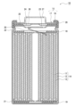
- FIG. 1 is a cross-sectional view of a non-aqueous electrolyte secondary battery that is an example of an embodiment
- FIG. 1 is a cross-sectional view of graphite particles of the present embodiment
- FIG. 1 is a cross-sectional view of a non-aqueous electrolyte secondary battery that is an example of an embodiment.
- the non-aqueous electrolyte secondary battery 10 shown in FIG. Insulating plates 18 and 19 arranged respectively in the respective parts, and a battery case 15 housing the above members.
- the battery case 15 is composed of a bottomed cylindrical case body 16 and a sealing member 17 that closes the opening of the case body 16 .
- Examples of the battery case 15 include a cylindrical or rectangular metal case, a resin case (pouch type battery) formed by laminating resin sheets, and the like.
- the case body 16 is, for example, a bottomed cylindrical metal container.
- a gasket 28 is provided between the case body 16 and the sealing member 17 to ensure hermeticity inside the battery.
- the case main body 16 has an overhanging portion 22 that supports the sealing member 17, for example, a portion of the side surface overhanging inward.
- the protruding portion 22 is preferably annularly formed along the circumferential direction of the case body 16 and supports the sealing member 17 on the upper surface thereof.
- the sealing body 17 has a structure in which a filter 23, a lower valve body 24, an insulating member 25, an upper valve body 26, and a cap 27 are layered in order from the electrode body 14 side.
- Each member constituting the sealing member 17 has, for example, a disk shape or a ring shape, and each member except for the insulating member 25 is electrically connected to each other.
- the lower valve body 24 and the upper valve body 26 are connected to each other at their central portions, and an insulating member 25 is interposed between their peripheral edge portions.
- the positive electrode lead 20 attached to the positive electrode 11 extends through the through hole of the insulating plate 18 toward the sealing member 17, and the negative electrode lead 21 attached to the negative electrode 12 extends toward the sealing member 17. It extends to the bottom side of the case body 16 through the outside of the insulating plate 19 .
- the positive electrode lead 20 is connected to the lower surface of the filter 23, which is the bottom plate of the sealing member 17, by welding or the like, and the cap 27, which is the top plate of the sealing member 17 electrically connected to the filter 23, serves as a positive electrode terminal.
- the negative lead 21 is connected to the inner surface of the bottom of the case body 16 by welding or the like, and the case body 16 serves as a negative terminal.
- the positive electrode 11, the negative electrode 12, the separator 13, and the nonaqueous electrolyte that constitute the nonaqueous electrolyte secondary battery 10 will be described in detail below.
- the positive electrode 11 is a long strip-shaped sheet member, and includes a positive electrode current collector and a positive electrode mixture layer disposed on the positive electrode current collector.
- the positive electrode current collector foils of metals such as aluminum and aluminum alloys that are stable in the potential range of the positive electrode, films having such metals arranged on the surface layer, and the like can be used.
- the positive electrode mixture layer includes, for example, a positive electrode active material, a binder, a conductive material, and the like.
- the positive electrode mixture layer is preferably formed on both sides of the positive electrode current collector.
- the positive electrode 11 is produced, for example, by coating a positive electrode mixture slurry containing a positive electrode active material, a binder, a conductive material, etc. on a positive electrode current collector, drying and rolling the coating film, and turning the positive electrode mixture layer into a positive electrode current collector. It can be manufactured by forming it on the body.
- the positive electrode active material is, for example, a lithium composite oxide capable of reversibly intercalating and deintercalating lithium.
- metal elements contained in the lithium composite oxide include Ni, Co, Mn, Al, B, Mg, Ti, V, Cr, Fe, Cu, Zn, Ga, Sr, Zr, Nb, In, Sn , Ta, W, and the like. Among them, it is preferable to contain at least one of Ni, Co, and Mn.
- An example of a suitable lithium composite oxide is represented by the general formula LiMO 2 (M is Ni and X, X is a metal element other than Ni, and the ratio of Ni to the total number of moles of metal elements excluding Li is is 50 mol % or more and 95 mol % or less).
- X in the above formula includes, for example, Co, Mn, Al, B, Mg, Ti, V, Cr, Fe, Cu, Zn, Ga, Sr, Zr, Nb, In, Sn, Ta, W, etc. .
- Examples of the conductive material contained in the positive electrode mixture layer include carbon black, acetylene black, ketjen black, graphene, fibrous carbon such as carbon nanotubes, and carbon materials such as graphite.
- the binder contained in the positive electrode mixture layer includes fluororesins such as polytetrafluoroethylene (PTFE) and polyvinylidene fluoride (PVdF), polyacrylonitrile (PAN), polyimide resins, acrylic resins, polyolefin resins, styrene-butadiene rubber (SBR), carboxymethyl cellulose (CMC) or salts thereof, polyacrylic acid (PAA) or salts thereof (PAA-Na, PAA-K, etc., may also be partially neutralized salts), polyethylene oxide (PEO), polyvinyl alcohol (PVA) and the like.
- fluororesins such as polytetrafluoroethylene (PTFE) and polyvinylidene fluoride (PVdF), polyacrylon
- the negative electrode 12 is a long strip-shaped sheet member, and includes a negative electrode current collector and a negative electrode mixture layer disposed on the negative electrode current collector.
- a negative electrode current collector for example, a foil of a metal such as copper or a copper alloy that is stable in the potential range of the negative electrode, a film having the metal on the surface layer, or the like can be used.
- the negative electrode mixture layer includes a negative electrode active material containing graphite particles and a Si-based material, and fibrous carbon.
- the negative electrode mixture layer 32 may additionally contain a binder or the like.
- the negative electrode 12 is formed by, for example, coating a negative electrode mixture slurry containing a negative electrode active material, fibrous carbon, a binder, etc. on a negative electrode current collector, drying and rolling the coating film, and forming a negative electrode mixture layer into a negative electrode collector. It can be manufactured by forming it on an electrical body.
- the graphite particles have a degree of graphitization in the range of 70-80, preferably in the range of 72-78, obtained by X-ray diffraction.
- the particles are harder than graphite particles having a degree of graphitization higher than the above range. Since the hard graphite particles are less likely to be crushed even when the negative electrode 12 is produced by rolling, appropriate voids are maintained in the negative electrode mixture layer, which is thought to contribute to the improvement of electrolyte permeability. If the degree of graphitization of the graphite particles is lower than the above range, side reactions with the non-aqueous electrolyte are accelerated, and the cycle characteristics of the battery tend to deteriorate.
- FIG. 2 is a cross-sectional view of the graphite particles of this embodiment.
- the graphite particle 30 has closed voids 34 (hereinafter referred to as internal voids 34) that are not connected from the inside of the particle to the particle surface, and and voids 36 (hereinafter referred to as external voids 36) connected to the particle surface.
- internal voids 34 closed voids 34
- external voids 36 voids 36
- the graphite particles 30 of the present embodiment have a particle internal porosity in the range of 1% to 5%.
- the particle internal porosity of the graphite particles 30 is in the range of 1% to 5%, preferably in the range of 2% to 5%.
- the particle internal porosity of the graphite particles is a two-dimensional value obtained from the ratio of the area of the internal voids of the graphite particles to the cross-sectional area of the graphite particles in the negative electrode mixture layer. Then, the particle internal porosity of the graphite particles is obtained by the following procedure.
- ⁇ Method for measuring internal porosity> Exposing a section of the negative electrode active material layer. Examples of the method of exposing the cross section include a method of cutting a part of the negative electrode and processing it with an ion milling device (eg, IM4000PLUS manufactured by Hitachi High-Tech) to expose the cross section of the negative electrode active material layer. (2) Using a scanning electron microscope, take a backscattered electron image of the cross section of the exposed negative electrode active material layer. The magnification for capturing the reflected electron image is 3,000 times to 5,000 times.
- an ion milling device eg, IM4000PLUS manufactured by Hitachi High-Tech
- the area of the graphite particle cross section refers to the area of the region surrounded by the outer periphery of the graphite particle, that is, the area of the entire cross section of the graphite particle.
- voids with a width of 3 ⁇ m or less may be difficult to distinguish between internal voids and external voids in image analysis. may be Then, from the calculated area of the graphite particle cross section and the area of the internal voids in the graphite particle cross section, the particle internal porosity of the graphite particles (area of internal voids in the cross section of the graphite particle ⁇ 100/area of the cross section of the graphite particle) is calculated.
- the particle internal porosity of the graphite particles is the average value of 10 graphite particles each.
- coke which is the main raw material
- coke which is the main raw material
- Graphite particles of a desired size are obtained by dividing.
- the internal porosity of the particles can be adjusted in the range of 1% to 5% depending on the particle size of the precursor after pulverization, the particle size of the precursor in an agglomerated state, and the like.
- the average particle diameter (volume-based median diameter D50) of the pulverized precursor is preferably in the range of 12 ⁇ m to 20 ⁇ m.
- the degree of graphitization of the graphite particles can be controlled by adjusting the firing temperature and firing time, for example.
- the firing temperature may be, for example, in the range of 2600°C to 2900°C.
- the baking time may be, for example, 10 hours or longer.
- the graphite particles of the present embodiment are not particularly limited to natural graphite, artificial graphite, or the like, but artificial graphite is preferable because it is easy to adjust the degree of graphitization and the internal porosity of the particles.
- the content of the graphite particles may be, for example, 90% by mass or more, or 95% by mass or more, relative to the total mass of the negative electrode active material.
- Si-based material that is the negative electrode active material examples include Si particles, alloy particles containing Si, and composite particles containing Si. These may be used alone or in combination of two or more.
- Si particles can be obtained, for example, by a vapor phase method or by pulverizing silicon chips, but they can be produced by any method.
- Alloy particles containing Si include, for example, alloys containing Si and metals selected from alkali metals, alkaline earth metals, transition metals, rare earth metals, or combinations thereof.
- the composite particles containing Si include, for example, a lithium ion conductive phase and Si particles dispersed in the lithium ion conductive phase.
- the lithium ion conductive phase is, for example, at least one selected from silicon oxide phases, silicate phases and carbon phases.
- the silicate phase contains, for example, at least one element selected from lithium, sodium, potassium, rubidium, cesium, francium, beryllium, magnesium, calcium, strontium, barium, and radium in terms of high lithium ion conductivity. preferably included.
- the silicate phase is preferably a silicate phase containing lithium (hereinafter sometimes referred to as a lithium silicate phase) because of its high lithium ion conductivity.
- Composite particles in which Si particles are dispersed in a silicon oxide phase are represented, for example, by the general formula SiO x (preferably in the range of 0 ⁇ x ⁇ 2, more preferably in the range of 0.5 ⁇ x ⁇ 1.6). be done.
- a composite particle in which Si particles are dispersed in a carbon phase is represented, for example, by the general formula Si x C y (preferably in the range of 0 ⁇ x ⁇ 1 and 0 ⁇ y ⁇ 1).
- a conductive film composed of a highly conductive material is formed on the surface of the particles of the Si-based material.
- conductive coatings include carbon coatings, metal coatings, and metal compound coatings. Carbon coatings are preferred from the viewpoint of electrochemical stability and the like.
- the carbon film can be formed by, for example, a CVD method using acetylene, methane, etc., a method of mixing coal pitch, petroleum pitch, phenol resin, etc. with a silicon-based active material and performing heat treatment.
- a conductive film may be formed by adhering a conductive filler such as carbon black to the particle surface of the Si-based material using a binder.
- the content of the Si-based material is in the range of 0.1% by mass to 5.0% by mass, preferably in the range of 1.0% by mass to 5.0% by mass, relative to the total mass of the negative electrode active material. be.
- the content of the Si-based material is within the above range, deterioration in the cycle characteristics of the battery is suppressed compared to when the content exceeds the above range, and the capacity of the battery can be increased compared to when the content is less than the above range. becomes.
- the fibrous carbon contained in the negative electrode mixture layer includes known materials used as conductive materials for batteries, such as carbon nanotubes (CNT), carbon nanofibers (CNF), and vapor grown carbon fibers (VGCF). , electrospun carbon fiber, polyacrylonitrile (PAN)-based carbon fiber, pitch-based carbon fiber, and the like.
- CNT carbon nanotubes
- CNF carbon nanofibers
- VGCF vapor grown carbon fibers
- electrospun carbon fiber polyacrylonitrile (PAN)-based carbon fiber
- PAN polyacrylonitrile
- the outermost diameter of fibrous carbon is, for example, in the range of 1 nm to 20 nm.
- the outermost diameter of fibrous carbon can be obtained by measuring the outer diameters of 50 arbitrary carbon fibrous carbons with a field emission scanning microscope (FE-SEM) or transmission electron microscope (TEM) and calculating the arithmetic mean.
- FE-SEM field emission scanning microscope
- TEM transmission electron microscope
- the fiber length of fibrous carbon is, for example, in the range of 0.1 ⁇ m to 20 ⁇ m.
- the fiber length of fibrous carbon can be determined by measuring the length of 50 arbitrary fibrous carbons with a field emission scanning microscope (FE-SEM) and calculating the arithmetic mean.
- FE-SEM field emission scanning microscope
- the fibrous carbon preferably contains carbon nanotubes, for example, in terms of suppressing deterioration of the cycle characteristics of the battery.
- Carbon nanotubes include single-walled carbon nanotubes, double-walled carbon nanotubes, and multi-walled carbon nanotubes.
- a single-walled carbon nanotube (SWCNT) is a carbon nanostructure in which one layer of graphene sheets constitutes a cylindrical shape, and a double-walled carbon nanotube has two layers of graphene sheets, which are concentrically stacked to form a single line.
- a multi-walled carbon nanotube is a carbon nanostructure in which three or more graphene sheets are concentrically laminated to form a single cylindrical shape.
- the graphene sheet refers to a layer in which carbon atoms of sp2 hybridized orbitals constituting a crystal of graphite (graphite) are positioned at vertexes of a regular hexagon.
- the shape of the carbon nanotube is not limited, but examples thereof include needle-like, cylindrical tube-like, fishbone-like (fishbone or cup laminated type), card-like (platelet), coil-like, and the like.
- the G/D ratio obtained by Raman spectroscopic measurement of carbon nanotubes (CNT) is preferably 40-130.
- the G/D ratio is the ratio of the peak intensity of G-Band (1550 cm -1 to 1600 cm -1 ) to the peak intensity of D-Band (1300 cm -1 to 1350 cm -1 ) in Raman spectroscopy. CNTs with a high G/D ratio indicate high crystallinity.
- the Raman spectroscopic spectrum of carbon nanotubes can be measured using a Raman spectrometer (eg, NRS-5500 manufactured by JASCO Corporation). For example, a carbon nanotube is dispensed onto a slide and flattened using a spatula to measure a prepared sample. Measurement conditions are, for example, as follows. Measurement time: 5 seconds Accumulation times: 2 Neutral density filter OD: 0.3 Objective lens magnification: 100 times Measurement range: 950 cm -1 to 1900 cm -1
- the content of fibrous carbon is, for example, 0.01% by mass to 0.1% by mass with respect to the total mass of the negative electrode active material in terms of increasing the capacity of the battery and suppressing deterioration of cycle characteristics. is preferred, and 0.01% by mass to 0.05% by mass is more preferred.
- the negative electrode mixture layer may contain a conductive material other than fibrous carbon in addition to fibrous carbon.
- conductive materials other than fibrous carbon include carbon black, acetylene black, and ketjen black.
- binder examples include the binders exemplified for the positive electrode 11 and the like.
- the content of the binder may be, for example, in the range of 0.5% by mass to 10% by mass with respect to the total mass of the negative electrode active material.
- separator 13 for example, a porous sheet having ion permeability and insulation is used. Specific examples of porous sheets include microporous thin films, woven fabrics, and non-woven fabrics. Suitable materials for the separator 13 include olefin resins such as polyethylene, polypropylene, copolymers containing at least one of ethylene and propylene, and cellulose. The separator 13 may have either a single layer structure or a laminated structure. A heat-resistant layer or the like may be formed on the surface of the separator 13 .
- the non-aqueous electrolyte contains a non-aqueous solvent and an electrolyte salt.
- Lithium salts such as LiFSI, LiTFSI, LiBF 4 , and LiPF 6 are used as electrolyte salts, for example.
- solvents include ethylene carbonate (EC), propylene carbonate (PC), dimethyl carbonate (DMC), ethyl methyl carbonate (EMC), diethyl carbonate (DEC), methyl acetate (MA), methyl propionate (MP), and the like. esters, ethers, nitriles, amides, and mixed solvents of two or more of these are used.
- the non-aqueous solvent may contain a halogen-substituted product obtained by substituting at least part of the hydrogen atoms of these solvents with halogen atoms such as fluorine.
- halogen-substituted compounds include fluorinated cyclic carbonates such as fluoroethylene carbonate (FEC), fluorinated chain carbonates, and fluorinated chain carboxylates such as methyl fluoropropionate (FMP).
- FEC fluoroethylene carbonate
- FMP fluorinated chain carboxylates
- Example 1 [Preparation of positive electrode] 95 parts by mass of LiCo0.979Zr0.001Mg0.01Al0.01O2 , 2.5 parts by mass of acetylene black (AB), and 2.5 parts by mass of polyvinylidene fluoride were mixed. , N-methyl-2-pyrrolidone (NMP) was added in an appropriate amount to prepare a positive electrode mixture slurry. Next, the positive electrode mixture slurry was applied to both surfaces of a positive electrode current collector made of an aluminum foil having a thickness of 15 ⁇ m, and the coating film was dried. After the dried coating film was rolled using a rolling roller, it was cut into a predetermined electrode plate size to prepare a positive electrode in which positive electrode mixture layers were formed on both sides of a positive electrode current collector.
- NMP N-methyl-2-pyrrolidone
- Coke was pulverized to an average particle size (median diameter D50) of 12 ⁇ m.
- Pitch as a binder was added to the pulverized coke, and the coke was agglomerated until the average particle size (median diameter D50) reached 17 ⁇ m.
- This aggregate was calcined at a temperature of 2800° C. for a predetermined time to be graphitized, and then sieved using a 250-mesh sieve to obtain graphite particles having an average particle diameter (median diameter D50) of 23 ⁇ m.
- the graphitization degree of the graphite particles was measured and found to be 75. The method for calculating the degree of graphitization is as described above.
- a negative electrode active material was prepared by mixing 97 parts by mass of the above graphite particles and 3 parts by mass of a Si-based material (composition: SiO).
- This negative electrode active material, carboxymethyl cellulose, styrene-butadiene rubber, and carbon nanotubes (CNT) were mixed in a mass ratio of 100:1.0:1.0:0.02.
- An appropriate amount of water was added to and mixed with this mixture to prepare a negative electrode mixture slurry.
- the negative electrode mixture slurry was applied to both surfaces of a negative electrode current collector made of copper foil having a thickness of 10 ⁇ m, and the coating film was dried. After the dried coating film was rolled using a rolling roller, it was cut into a predetermined electrode plate size to prepare a negative electrode in which negative electrode mixture layers were formed on both sides of a negative electrode current collector.
- the internal porosity of the graphite particles was measured and found to be 3%.
- the method for measuring the internal porosity of the particles is as described above.
- Ethylene carbonate (EC), propylene carbonate (PC) and ethylmethyl carbonate (EMC) were mixed in a volume ratio of 10:10:80.
- a non-aqueous electrolyte was prepared by dissolving LiPF 6 in the mixed solvent so as to have a concentration of 1.0 mol/L.
- a separator made of a polyethylene microporous membrane was placed between the positive electrode and the negative electrode, and these were wound, and a tape was adhered to the outermost peripheral surface to prepare a cylindrical wound electrode assembly. This electrode body was pressed into a flat electrode body.
- a sheet-like laminate material having a five-layer structure of resin layer (polypropylene)/adhesive layer/aluminum alloy layer/adhesive layer/resin layer (polypropylene) was prepared. This laminate material was folded back to form a bottom portion, thereby producing an exterior body having a cup-shaped electrode housing space. Then, in a glove box under an argon atmosphere, the electrode body and the non-aqueous electrolyte were stored in the electrode body storage space in the exterior body. After depressurizing the interior of the exterior body and impregnating the separator with the non-aqueous electrolyte, the opening of the exterior body was sealed to produce a non-aqueous electrolyte secondary battery.
- Example 2 Graphite particles were produced in the same manner as in Example 1, except that the sintering time for graphitizing the aggregates by sintering them at a temperature of 2800° C. was shorter than in Example 1. The graphitization degree of the graphite particles of Example 2 was measured and found to be 72. A negative electrode was produced in the same manner as in Example 1 except that the graphite particles were used, and a non-aqueous electrolyte secondary battery was produced in the same manner as in Example 1 using this negative electrode. From the negative electrode of Example 2, the internal porosity of the graphite particles was measured and found to be 3%.
- Example 3 In the preparation of the negative electrode, a non-aqueous electrolyte secondary was prepared in the same manner as in Example 1, except that a negative electrode active material was prepared by mixing 99 parts by mass of graphite particles and 1 part by mass of a Si-based material (composition: SiO). A battery was produced.
- Example 4 In the preparation of the negative electrode, a non-aqueous electrolyte secondary was prepared in the same manner as in Example 1, except that a negative electrode active material was prepared by mixing 96 parts by mass of graphite particles and 4 parts by mass of a Si-based material (composition: SiO). A battery was produced.
- Graphite particles were produced in the same manner as in Example 1, except that the aggregates were sintered at a temperature of 3000°C.
- the graphitization degree of the graphite particles of Comparative Example 1 was measured and found to be 85.
- the negative electrode was prepared in the same manner as in Example 1, except that only the graphite particles of Comparative Example 1 were used as the negative electrode active material, no Si-based material was used, and carbon nanotubes (CNT) were not added.
- a non-aqueous electrolyte secondary battery was produced in the same manner as in Example 1 using this negative electrode.
- the graphitized block-shaped molded body was pulverized and sieved using a 250-mesh sieve to obtain graphite particles having an average particle diameter (median diameter D50) of 23 ⁇ m.
- the graphitization degree of the graphite particles was measured and found to be 85.
- a negative electrode was prepared in the same manner as in Example 1, except that the graphite particles of Comparative Example 1 were used in the preparation of the negative electrode, and carbon nanotubes (CNT) were not added. Similarly, a non-aqueous electrolyte secondary battery was produced.
- Example 4 A negative electrode was prepared in the same manner as in Example 1 except that the graphite particles of Comparative Example 1 were used in the preparation of the negative electrode, and a non-aqueous electrolyte secondary battery was prepared in the same manner as in Example 1 using this negative electrode. .
- a negative electrode was prepared in the same manner as in Example 1 except that carbon nanotubes (CNT) were not added in the preparation of the negative electrode, and a non-aqueous electrolyte secondary battery was prepared in the same manner as in Example 1 using this negative electrode. bottom.
- CNT carbon nanotubes
- Example 6 A negative electrode was prepared in the same manner as in Example 1, except that the graphite particles of Example 2 were used in the preparation of the negative electrode, and carbon nanotubes (CNT) were not added. Similarly, a non-aqueous electrolyte secondary battery was produced.
- Example 7 A negative electrode was prepared in the same manner as in Example 1, except that a Si-based material was not used as the negative electrode active material and carbon nanotubes (CNT) were not added in the preparation of the negative electrode.
- a non-aqueous electrolyte secondary battery was produced in the same manner as in Example 1.
- Graphite particles were produced in the same manner as in Comparative Example 2, except that the agglomerates were sintered at a temperature of 2800°C. The graphitization degree of the graphite particles of Comparative Example 8 was measured and found to be 75.
- a negative electrode was prepared in the same manner as in Example 1 except that the graphite particles of Comparative Example 8 were used in the preparation of the negative electrode, and a non-aqueous electrolyte secondary battery was prepared in the same manner as in Example 1 using this negative electrode. . From the negative electrode of Comparative Example 8, the internal porosity of the graphite particles was measured and found to be 10%.
- a non-aqueous electrolyte secondary was prepared in the same manner as in Example 1, except that a negative electrode active material was prepared by mixing 94 parts by mass of graphite particles and 6 parts by mass of a Si-based material (composition: SiO). A battery was produced.
- Table 1 summarizes the test results for each example and each comparative example. However, regarding the battery capacity and the electrolyte permeation time, the result of Comparative Example 1 was used as a standard (100), and the results of other examples and comparative examples were shown as relative values.
- the negative electrode mixture layer includes a negative electrode active material containing graphite particles and a Si-based material, and fibrous carbon, the graphite particles have a degree of graphitization in the range of 70 to 80, and the graphite particles have an internal porosity of 1. % to 5%, and the content of the Si-based material is in the range of 0.1% by mass to 5.0% by mass with respect to the total mass of the negative electrode active material.
- Comparative Example 4 showed a higher battery capacity than Comparative Example 1, exhibited an effect of suppressing deterioration of cycle characteristics equal to or greater than that of Comparative Example 1, and improved the electrolyte permeability of the negative electrode from Comparative Example 1.
Abstract
An electrode for a nonaqueous electrolyte secondary battery according to one aspect of the present disclosure is characterized by being provided with a negative electrode current collector and a negative electrode composite layer formed on the negative electrode current collector, wherein: the negative electrode composite layer includes carbon fibers and a negative electrode active substance containing graphite particles and a Si material; the graphite particles have a graphitization degree, obtained by X-ray diffraction, in the range of 70-80, and a particle internal porosity in the range of 1-5%; and the Si material content is in the range of 0.1-5.0 mass% relative to the total mass of the negative electrode active substance.
Description
本開示は、非水電解液二次電池用負極及び非水電解液二次電池に関する。
The present disclosure relates to a negative electrode for a non-aqueous electrolyte secondary battery and a non-aqueous electrolyte secondary battery.
非水電解液二次電池の負極には炭素系材料を使用するのが一般的であるが(例えば、特許文献1~3)、電池の高容量化のために、Si系材料を負極に使用することが検討されている。しかしながら、Si系材料はリチウムの充放電を繰り返すことで膨張収縮し、これにより劣化するため、電池のサイクル特性に課題があった。例えば、特許文献4には、電池のサイクル特性の低下を抑制するため、ラマン分光測定により得られるラマンスペクトルにおいて2600~2800cm-1にピークを有するカーボンナノチューブと、黒鉛と、組成がSiOx(但し、0<x≦2)で表されるケイ素酸化物と、を含む負極が提案されている。
Carbon-based materials are generally used for the negative electrodes of non-aqueous electrolyte secondary batteries (for example, Patent Documents 1 to 3), but Si-based materials are used for the negative electrodes in order to increase the capacity of the battery. is being considered. However, the Si-based material expands and shrinks as lithium is repeatedly charged and discharged, and this causes deterioration, which poses a problem in terms of battery cycle characteristics. For example, in Patent Document 4, a carbon nanotube having a peak at 2600 to 2800 cm −1 in a Raman spectrum obtained by Raman spectrometry, graphite, and SiO x (wherein the composition is , 0<x≦2).
ところで、昨今の非水電解液二次電池に対しては、電池の高容量化、サイクル特性の低下抑制に加え、電池の急速充放電性能に影響を与える負極の電解液浸透性を改善することも望まれている。
By the way, for recent non-aqueous electrolyte secondary batteries, in addition to increasing the capacity of the battery and suppressing the deterioration of cycle characteristics, it is necessary to improve the electrolyte permeability of the negative electrode, which affects the rapid charge and discharge performance of the battery. is also desired.
そこで、本開示は、電池の高容量化、電池のサイクル特性の低下抑制、及び負極の電解液浸透性の改善を可能とする非水電解液二次電池用負極及び当該負極を備える非水電解液二次電池を提供することを目的とする。
Therefore, the present disclosure provides a negative electrode for a non-aqueous electrolyte secondary battery that can increase the capacity of the battery, suppress the deterioration of the cycle characteristics of the battery, and improve the electrolyte permeability of the negative electrode, and a non-aqueous electrolysis comprising the negative electrode. An object of the present invention is to provide a liquid secondary battery.
本開示の一態様である非水電解液二次電池用負極は、負極集電体と、前記負極集電体上に形成された負極合材層とを備え、前記負極合材層は、黒鉛粒子及びSi系材料を含む負極活物質と、繊維状炭素とを含み、前記黒鉛粒子は、X線回折法によって得られる黒鉛化度が70~80の範囲であり、粒子内部空隙率が1%~5%の範囲であり、前記Si系材料の含有量は、前記負極活物質の総質量に対して、0.1質量%~5.0質量%の範囲であることを特徴とする。
A negative electrode for a non-aqueous electrolyte secondary battery according to one aspect of the present disclosure includes a negative electrode current collector and a negative electrode mixture layer formed on the negative electrode current collector, wherein the negative electrode mixture layer is made of graphite. The graphite particles contain a negative electrode active material containing particles and a Si-based material, and fibrous carbon, and the graphite particles have a degree of graphitization in the range of 70 to 80 as determined by an X-ray diffraction method, and an internal porosity of the particles of 1%. 5%, and the content of the Si-based material is in the range of 0.1% by mass to 5.0% by mass with respect to the total mass of the negative electrode active material.
本開示によれば、電池の高容量化、電池のサイクル特性の低下抑制、及び負極の電解液浸透性の改善を可能とする非水電解液二次電池用負極及び当該負極を備える非水電解液二次電池を提供することができる。
According to the present disclosure, a negative electrode for a non-aqueous electrolyte secondary battery and a non-aqueous electrolysis comprising the negative electrode that can increase the capacity of the battery, suppress the deterioration of the cycle characteristics of the battery, and improve the electrolyte permeability of the negative electrode A liquid secondary battery can be provided.
以下、図面を参照しながら、本開示に係る非水電解液二次電池の実施形態について詳説する。
Hereinafter, embodiments of the non-aqueous electrolyte secondary battery according to the present disclosure will be described in detail with reference to the drawings.
図1は、実施形態の一例である非水電解液二次電池の断面図である。図1に示す非水電解液二次電池10は、正極11及び負極12がセパレータ13を介して巻回されてなる巻回型の電極体14と、非水電解液と、電極体14の上下にそれぞれ配置された絶縁板18,19と、上記部材を収容する電池ケース15と、を備える。電池ケース15は、有底円筒形状のケース本体16と、ケース本体16の開口部を塞ぐ封口体17とにより構成される。電池ケース15としては、円筒形、角形等の金属製ケース、樹脂シートをラミネートして形成された樹脂製ケース(パウチ型電池)などが例示できる。
FIG. 1 is a cross-sectional view of a non-aqueous electrolyte secondary battery that is an example of an embodiment. The non-aqueous electrolyte secondary battery 10 shown in FIG. Insulating plates 18 and 19 arranged respectively in the respective parts, and a battery case 15 housing the above members. The battery case 15 is composed of a bottomed cylindrical case body 16 and a sealing member 17 that closes the opening of the case body 16 . Examples of the battery case 15 include a cylindrical or rectangular metal case, a resin case (pouch type battery) formed by laminating resin sheets, and the like.
ケース本体16は、例えば有底円筒形状の金属製容器である。ケース本体16と封口体17との間にはガスケット28が設けられ、電池内部の密閉性が確保される。ケース本体16は、例えば側面部の一部が内側に張出した、封口体17を支持する張り出し部22を有する。張り出し部22は、ケース本体16の周方向に沿って環状に形成されることが好ましく、その上面で封口体17を支持する。
The case body 16 is, for example, a bottomed cylindrical metal container. A gasket 28 is provided between the case body 16 and the sealing member 17 to ensure hermeticity inside the battery. The case main body 16 has an overhanging portion 22 that supports the sealing member 17, for example, a portion of the side surface overhanging inward. The protruding portion 22 is preferably annularly formed along the circumferential direction of the case body 16 and supports the sealing member 17 on the upper surface thereof.
封口体17は、電極体14側から順に、フィルタ23、下弁体24、絶縁部材25、上弁体26、及びキャップ27が積層された構造を有する。封口体17を構成する各部材は、例えば円板形状又はリング形状を有し、絶縁部材25を除く各部材は互いに電気的に接続されている。下弁体24と上弁体26は各々の中央部で互いに接続され、各々の周縁部の間には絶縁部材25が介在している。内部短絡等による発熱で非水電解液二次電池10の内圧が上昇すると、例えば下弁体24が上弁体26をキャップ27側に押し上げるように変形して破断し、下弁体24と上弁体26の間の電流経路が遮断される。さらに内圧が上昇すると、上弁体26が破断し、キャップ27の開口部からガスが排出される。
The sealing body 17 has a structure in which a filter 23, a lower valve body 24, an insulating member 25, an upper valve body 26, and a cap 27 are layered in order from the electrode body 14 side. Each member constituting the sealing member 17 has, for example, a disk shape or a ring shape, and each member except for the insulating member 25 is electrically connected to each other. The lower valve body 24 and the upper valve body 26 are connected to each other at their central portions, and an insulating member 25 is interposed between their peripheral edge portions. When the internal pressure of the non-aqueous electrolyte secondary battery 10 rises due to heat generation due to an internal short circuit or the like, for example, the lower valve body 24 is deformed to push the upper valve body 26 upward toward the cap 27 and is broken. A current path between the valve bodies 26 is cut off. When the internal pressure further increases, the upper valve body 26 is broken and the gas is discharged from the opening of the cap 27 .
図1に示す非水電解液二次電池10では、正極11に取り付けられた正極リード20が絶縁板18の貫通孔を通って封口体17側に延び、負極12に取り付けられた負極リード21が絶縁板19の外側を通ってケース本体16の底部側に延びている。正極リード20は封口体17の底板であるフィルタ23の下面に溶接等で接続され、フィルタ23と電気的に接続された封口体17の天板であるキャップ27が正極端子となる。負極リード21はケース本体16の底部内面に溶接等で接続され、ケース本体16が負極端子となる。
In the non-aqueous electrolyte secondary battery 10 shown in FIG. 1, the positive electrode lead 20 attached to the positive electrode 11 extends through the through hole of the insulating plate 18 toward the sealing member 17, and the negative electrode lead 21 attached to the negative electrode 12 extends toward the sealing member 17. It extends to the bottom side of the case body 16 through the outside of the insulating plate 19 . The positive electrode lead 20 is connected to the lower surface of the filter 23, which is the bottom plate of the sealing member 17, by welding or the like, and the cap 27, which is the top plate of the sealing member 17 electrically connected to the filter 23, serves as a positive electrode terminal. The negative lead 21 is connected to the inner surface of the bottom of the case body 16 by welding or the like, and the case body 16 serves as a negative terminal.
以下、非水電解液二次電池10を構成する正極11、負極12、セパレータ13、非水電解液について詳述する。
The positive electrode 11, the negative electrode 12, the separator 13, and the nonaqueous electrolyte that constitute the nonaqueous electrolyte secondary battery 10 will be described in detail below.
[正極]
正極11は、長尺帯状のシート部材であり、正極集電体と、正極集電体上に配置された正極合材層とを備える。正極集電体には、アルミニウム、アルミニウム合金などの正極の電位範囲で安定な金属の箔、当該金属を表層に配置したフィルム等を用いることができる。正極合材層は、例えば、正極活物質、結着材、導電材等を含んで構成される。正極合材層は、正極集電体の両面に形成されることが好ましい。正極11は、例えば、正極活物質、結着材、導電材等を含む正極合材スラリーを正極集電体上に塗布し、塗膜を乾燥、圧延して、正極合材層を正極集電体上に形成することにより製造できる。 [Positive electrode]
Thepositive electrode 11 is a long strip-shaped sheet member, and includes a positive electrode current collector and a positive electrode mixture layer disposed on the positive electrode current collector. As the positive electrode current collector, foils of metals such as aluminum and aluminum alloys that are stable in the potential range of the positive electrode, films having such metals arranged on the surface layer, and the like can be used. The positive electrode mixture layer includes, for example, a positive electrode active material, a binder, a conductive material, and the like. The positive electrode mixture layer is preferably formed on both sides of the positive electrode current collector. The positive electrode 11 is produced, for example, by coating a positive electrode mixture slurry containing a positive electrode active material, a binder, a conductive material, etc. on a positive electrode current collector, drying and rolling the coating film, and turning the positive electrode mixture layer into a positive electrode current collector. It can be manufactured by forming it on the body.
正極11は、長尺帯状のシート部材であり、正極集電体と、正極集電体上に配置された正極合材層とを備える。正極集電体には、アルミニウム、アルミニウム合金などの正極の電位範囲で安定な金属の箔、当該金属を表層に配置したフィルム等を用いることができる。正極合材層は、例えば、正極活物質、結着材、導電材等を含んで構成される。正極合材層は、正極集電体の両面に形成されることが好ましい。正極11は、例えば、正極活物質、結着材、導電材等を含む正極合材スラリーを正極集電体上に塗布し、塗膜を乾燥、圧延して、正極合材層を正極集電体上に形成することにより製造できる。 [Positive electrode]
The
正極活物質は、例えば、可逆的にリチウムを挿入・脱離可能なリチウム複合酸化物である。リチウム複合酸化物に含有される金属元素としては、例えば、Ni、Co、Mn、Al、B、Mg、Ti、V、Cr、Fe、Cu、Zn、Ga、Sr、Zr、Nb、In、Sn、Ta、W等が挙げられる。中でも、Ni、Co、Mnの少なくとも1種を含有することが好ましい。好適なリチウム複合酸化物の一例としては、一般式LiMO2(MはNi及びXであり、XはNi以外の金属元素であり、Niの割合は、Liを除く金属元素の総モル数に対して50モル%以上95モル%以下である)で表される複合酸化物が挙げられる。上記式中のXは、例えば、Co、Mn、Al、B、Mg、Ti、V、Cr、Fe、Cu、Zn、Ga、Sr、Zr、Nb、In、Sn、Ta、W等が挙げられる。
The positive electrode active material is, for example, a lithium composite oxide capable of reversibly intercalating and deintercalating lithium. Examples of metal elements contained in the lithium composite oxide include Ni, Co, Mn, Al, B, Mg, Ti, V, Cr, Fe, Cu, Zn, Ga, Sr, Zr, Nb, In, Sn , Ta, W, and the like. Among them, it is preferable to contain at least one of Ni, Co, and Mn. An example of a suitable lithium composite oxide is represented by the general formula LiMO 2 (M is Ni and X, X is a metal element other than Ni, and the ratio of Ni to the total number of moles of metal elements excluding Li is is 50 mol % or more and 95 mol % or less). X in the above formula includes, for example, Co, Mn, Al, B, Mg, Ti, V, Cr, Fe, Cu, Zn, Ga, Sr, Zr, Nb, In, Sn, Ta, W, etc. .
正極合材層に含まれる導電材としては、カーボンブラック、アセチレンブラック、ケッチェンブラック、グラフェン、カーボンナノチューブ等の繊維状炭素、黒鉛等の炭素材料が例示できる。正極合材層に含まれる結着材としては、ポリテトラフルオロエチレン(PTFE)、ポリフッ化ビニリデン(PVdF)等のフッ素樹脂、ポリアクリロニトリル(PAN)、ポリイミド系樹脂、アクリル系樹脂、ポリオレフィン系樹脂、スチレン-ブタジエンゴム(SBR)、カルボキシメチルセルロース(CMC)又はその塩、ポリアクリル酸(PAA)又はその塩(PAA-Na、PAA-K等、また部分中和型の塩であってもよい)、ポリエチレンオキシド(PEO)、ポリビニルアルコール(PVA)等が挙げられる。
Examples of the conductive material contained in the positive electrode mixture layer include carbon black, acetylene black, ketjen black, graphene, fibrous carbon such as carbon nanotubes, and carbon materials such as graphite. The binder contained in the positive electrode mixture layer includes fluororesins such as polytetrafluoroethylene (PTFE) and polyvinylidene fluoride (PVdF), polyacrylonitrile (PAN), polyimide resins, acrylic resins, polyolefin resins, styrene-butadiene rubber (SBR), carboxymethyl cellulose (CMC) or salts thereof, polyacrylic acid (PAA) or salts thereof (PAA-Na, PAA-K, etc., may also be partially neutralized salts), polyethylene oxide (PEO), polyvinyl alcohol (PVA) and the like.
[負極]
負極12は、長尺帯状のシート部材であり、負極集電体と、負極集電体上に配置された負極合材層とを備える。負極集電体には、例えば、銅、銅合金などの負極の電位範囲で安定な金属の箔、当該金属を表層に配置したフィルム等を用いることができる。 [Negative electrode]
Thenegative electrode 12 is a long strip-shaped sheet member, and includes a negative electrode current collector and a negative electrode mixture layer disposed on the negative electrode current collector. For the negative electrode current collector, for example, a foil of a metal such as copper or a copper alloy that is stable in the potential range of the negative electrode, a film having the metal on the surface layer, or the like can be used.
負極12は、長尺帯状のシート部材であり、負極集電体と、負極集電体上に配置された負極合材層とを備える。負極集電体には、例えば、銅、銅合金などの負極の電位範囲で安定な金属の箔、当該金属を表層に配置したフィルム等を用いることができる。 [Negative electrode]
The
負極合材層は、黒鉛粒子及びSi系材料を含む負極活物質、繊維状炭素を含む。負極合材層32は、その他に、結着材等を含んでいてもよい。
The negative electrode mixture layer includes a negative electrode active material containing graphite particles and a Si-based material, and fibrous carbon. The negative electrode mixture layer 32 may additionally contain a binder or the like.
負極12は、例えば、負極活物質、繊維状炭素、結着材等を含む負極合材スラリーを負極集電体上に塗布し、塗膜を乾燥、圧延して、負極合材層を負極集電体上に形成することにより製造できる。
The negative electrode 12 is formed by, for example, coating a negative electrode mixture slurry containing a negative electrode active material, fibrous carbon, a binder, etc. on a negative electrode current collector, drying and rolling the coating film, and forming a negative electrode mixture layer into a negative electrode collector. It can be manufactured by forming it on an electrical body.
黒鉛粒子は、X線回折法によって得られる黒鉛化度が70~80の範囲であり、好ましくは72~78の範囲である。黒鉛粒子の黒鉛化度が上記範囲の場合、上記範囲より高い黒鉛粒子と比較して、硬質な粒子となる。硬質な黒鉛粒子は、負極12の作製時の圧延によっても潰れ難いため、負極合材層に適度な空隙が維持され、電解液浸透性の改善に寄与すると考えられる。なお、黒鉛粒子の黒鉛化度が上記範囲より低いと、非水電解液との副反応が促進される等で、電池のサイクル特性が低下する傾向にある。
The graphite particles have a degree of graphitization in the range of 70-80, preferably in the range of 72-78, obtained by X-ray diffraction. When the degree of graphitization of the graphite particles is within the above range, the particles are harder than graphite particles having a degree of graphitization higher than the above range. Since the hard graphite particles are less likely to be crushed even when the negative electrode 12 is produced by rolling, appropriate voids are maintained in the negative electrode mixture layer, which is thought to contribute to the improvement of electrolyte permeability. If the degree of graphitization of the graphite particles is lower than the above range, side reactions with the non-aqueous electrolyte are accelerated, and the cycle characteristics of the battery tend to deteriorate.
ここで、X線回折法とは、CuKαをX線源、標準物質に高純度シリコンを使用し、黒鉛粒子に対し回折パターンを測定するものである。そして、黒鉛粒子の(002)面の回折パターンのピーク位置及び半値幅から、黒鉛粒子の(002)面の面間隔d002(Å)を求め、このd002の値を以下の式に当てはめて、黒鉛化度Pを算出する。
黒鉛化度P=100×(3.44-d002/3.44-3.354) Here, the X-ray diffraction method uses CuKα as an X-ray source and high-purity silicon as a standard substance to measure the diffraction pattern of graphite particles. Then, from the peak position and half width of the diffraction pattern of the (002) plane of the graphite particle, the interplanar spacing d002 (Å) of the (002) plane of the graphite particle is obtained. The degree of quenching P is calculated.
Degree of graphitization P = 100 × (3.44-d002/3.44-3.354)
図2は、本実施形態の黒鉛粒子の断面図である。図2に示すように、本実施形態の黒鉛粒子30は、黒鉛粒子30の断面視において、粒子内部から粒子表面につながっていない閉じられた空隙34(以下、内部空隙34)と、粒子内部から粒子表面につながっている空隙36(以下、外部空隙36)とを有する。
FIG. 2 is a cross-sectional view of the graphite particles of this embodiment. As shown in FIG. 2, in the cross-sectional view of the graphite particle 30 of the present embodiment, the graphite particle 30 has closed voids 34 (hereinafter referred to as internal voids 34) that are not connected from the inside of the particle to the particle surface, and and voids 36 (hereinafter referred to as external voids 36) connected to the particle surface.
本実施形態の黒鉛粒子30は、粒子内部空隙率が1%~5%の範囲である。黒鉛粒子30の粒子内部空隙率は、1%~5%の範囲であり、好ましくは2%~5%の範囲である。黒鉛粒子の粒子内部空隙率を上記範囲とすることで、上記範囲外の場合と比較して、負極合材層に適度な空隙が維持され、電解液浸透性の改善に寄与すると考えられる。ここで、黒鉛粒子の粒子内部空隙率とは、負極合材層内の黒鉛粒子の断面積に対する黒鉛粒子の内部空隙の面積の割合から求めた2次元値である。そして、黒鉛粒子の粒子内部空隙率は、以下の手順で求められる。
The graphite particles 30 of the present embodiment have a particle internal porosity in the range of 1% to 5%. The particle internal porosity of the graphite particles 30 is in the range of 1% to 5%, preferably in the range of 2% to 5%. By setting the particle internal porosity of the graphite particles within the above range, it is believed that a suitable amount of voids is maintained in the negative electrode mixture layer compared to a case outside the above range, thereby contributing to improvement in electrolyte permeability. Here, the particle internal porosity of the graphite particles is a two-dimensional value obtained from the ratio of the area of the internal voids of the graphite particles to the cross-sectional area of the graphite particles in the negative electrode mixture layer. Then, the particle internal porosity of the graphite particles is obtained by the following procedure.
<内部空隙率の測定方法>
(1)負極活物質層の断面を露出させる。断面を露出させる方法としては、例えば、負極の一部を切り取り、イオンミリング装置(例えば、日立ハイテク社製、IM4000PLUS)で加工し、負極活物質層の断面を露出させる方法が挙げられる。
(2)走査型電子顕微鏡を用いて、上記露出させた負極活物質層の断面の反射電子像を撮影する。反射電子像を撮影する際の倍率は、3千倍から5千倍である。
(3)上記により得られた断面像をコンピュータに取り込み、画像解析ソフト(例えば、アメリカ国立衛生研究所製、ImageJ)を用いて二値化処理を行い、断面像内の粒子断面を黒色とし、粒子断面に存在する空隙を白色として変換した二値化処理画像を得る。
(4)二値化処理画像から、粒径5μm~50μmの黒鉛粒子を選択し、当該黒鉛粒子断面の面積、及び当該黒鉛粒子断面に存在する内部空隙の面積を算出する。ここで、黒鉛粒子断面の面積とは、黒鉛粒子の外周で囲まれた領域の面積、すなわち、黒鉛粒子の断面部分全ての面積を指している。また、黒鉛粒子断面に存在する空隙のうち幅が3μm以下の空隙については、画像解析上、内部空隙か外部空隙かの判別が困難となる場合があるため、幅が3μm以下の空隙は内部空隙としてもよい。そして、算出した黒鉛粒子断面の面積及び黒鉛粒子断面の内部空隙の面積から、黒鉛粒子の粒子内部空隙率(黒鉛粒子断面の内部空隙の面積×100/黒鉛粒子断面の面積)を算出する。黒鉛粒子の粒子内部空隙率は、黒鉛粒子それぞれ10個の平均値とする。 <Method for measuring internal porosity>
(1) Exposing a section of the negative electrode active material layer. Examples of the method of exposing the cross section include a method of cutting a part of the negative electrode and processing it with an ion milling device (eg, IM4000PLUS manufactured by Hitachi High-Tech) to expose the cross section of the negative electrode active material layer.
(2) Using a scanning electron microscope, take a backscattered electron image of the cross section of the exposed negative electrode active material layer. The magnification for capturing the reflected electron image is 3,000 times to 5,000 times.
(3) The cross-sectional image obtained as described above is captured in a computer, and subjected to binarization processing using image analysis software (for example, ImageJ, manufactured by the National Institutes of Health, USA) to turn the particle cross section in the cross-sectional image black, A binarized image is obtained in which voids present in the cross section of the particle are converted to white.
(4) Graphite particles with a particle size of 5 μm to 50 μm are selected from the binarized image, and the area of the cross section of the graphite particles and the area of internal voids present in the cross section of the graphite particles are calculated. Here, the area of the graphite particle cross section refers to the area of the region surrounded by the outer periphery of the graphite particle, that is, the area of the entire cross section of the graphite particle. In addition, among the voids present in the cross section of the graphite particles, voids with a width of 3 μm or less may be difficult to distinguish between internal voids and external voids in image analysis. may be Then, from the calculated area of the graphite particle cross section and the area of the internal voids in the graphite particle cross section, the particle internal porosity of the graphite particles (area of internal voids in the cross section of the graphite particle×100/area of the cross section of the graphite particle) is calculated. The particle internal porosity of the graphite particles is the average value of 10 graphite particles each.
本実施形態の黒鉛粒子の製造方法の一例について説明する。例えば、主原料となるコークス(前駆体)を所定サイズに粉砕し、それらを結着材で凝集させた状態で、所定の焼成温度及び所定の焼成時間で焼成し、黒鉛化させた後、篩い分けることで、所望のサイズの黒鉛粒子を得る。ここで、粉砕後の前駆体の粒径や凝集させた状態の前駆体の粒径等によって、粒子内部空隙率を1%~5%の範囲に調整することができる。例えば、粉砕後の前駆体の平均粒径(体積基準のメジアン径D50)を12μm~20μmの範囲とすることが好ましい。また、黒鉛粒子の黒鉛化度は、例えば、焼成温度及び焼成時間を調整することにより制御できる。焼成温度は、例えば、2600℃~2900℃の範囲でよい。焼成時間は、例えば、10時間以上でよい。
An example of the method for producing graphite particles of the present embodiment will be described. For example, coke (precursor), which is the main raw material, is pulverized to a predetermined size, aggregated with a binder, fired at a predetermined firing temperature and for a predetermined firing time, graphitized, and then sieved. Graphite particles of a desired size are obtained by dividing. Here, the internal porosity of the particles can be adjusted in the range of 1% to 5% depending on the particle size of the precursor after pulverization, the particle size of the precursor in an agglomerated state, and the like. For example, the average particle diameter (volume-based median diameter D50) of the pulverized precursor is preferably in the range of 12 μm to 20 μm. Also, the degree of graphitization of the graphite particles can be controlled by adjusting the firing temperature and firing time, for example. The firing temperature may be, for example, in the range of 2600°C to 2900°C. The baking time may be, for example, 10 hours or longer.
本実施形態の黒鉛粒子は、天然黒鉛、人造黒鉛等、特に限定されないが、黒鉛化度や粒子内部空隙率の調整が容易である等の点で、人造黒鉛が好ましい。黒鉛粒子の含有量は、例えば、負極活物質の総質量に対して、90質量%以上でよいし、又は95質量%以上でよい。
The graphite particles of the present embodiment are not particularly limited to natural graphite, artificial graphite, or the like, but artificial graphite is preferable because it is easy to adjust the degree of graphitization and the internal porosity of the particles. The content of the graphite particles may be, for example, 90% by mass or more, or 95% by mass or more, relative to the total mass of the negative electrode active material.
負極活物質であるSi系材料としては、例えば、Si粒子、Siを含む合金粒子、及びSiを含む複合化物粒子等が挙げられる。これらは、単独でもよく、2種類以上を組み合わせてもよい。
Examples of the Si-based material that is the negative electrode active material include Si particles, alloy particles containing Si, and composite particles containing Si. These may be used alone or in combination of two or more.
Si粒子は、例えば、気相法やシリコン切粉を微粉砕すること等により得られるが、どのような方法で製造されたものでもよい。Siを含む合金粒子は、例えば、Siと、アルカリ金属、アルカリ土類金属、遷移金属、希土類金属、またはこれらの組合せから選択される金属と、を含む合金が挙げられる。Siを含む複合化物粒子は、例えば、リチウムイオン導電相と、リチウムイオン導電相に分散しているSi粒子と、を含む。リチウムイオン導電相は、例えば、ケイ素酸化物相、シリケート相及び炭素相から選択される少なくとも1種である。
Si particles can be obtained, for example, by a vapor phase method or by pulverizing silicon chips, but they can be produced by any method. Alloy particles containing Si include, for example, alloys containing Si and metals selected from alkali metals, alkaline earth metals, transition metals, rare earth metals, or combinations thereof. The composite particles containing Si include, for example, a lithium ion conductive phase and Si particles dispersed in the lithium ion conductive phase. The lithium ion conductive phase is, for example, at least one selected from silicon oxide phases, silicate phases and carbon phases.
シリケート相は、例えば、リチウムイオン伝導性が高い等の点から、リチウム、ナトリウム、カリウム、ルビジウム、セシウム、フランシウム、ベリリウム、マグネシウム、カルシウム、ストロンチウム、バリウム、ラジウムから選択される少なくとも1種の元素を含むことが好ましい。中でも、シリケート相は、リチウムイオン伝導性が高い等の点から、リチウムを含むシリケート相(以下、リチウムシリケート相と称する場合がある)が好ましい。
The silicate phase contains, for example, at least one element selected from lithium, sodium, potassium, rubidium, cesium, francium, beryllium, magnesium, calcium, strontium, barium, and radium in terms of high lithium ion conductivity. preferably included. Among them, the silicate phase is preferably a silicate phase containing lithium (hereinafter sometimes referred to as a lithium silicate phase) because of its high lithium ion conductivity.
リチウムシリケート相は、例えば、式:Li2zSiO2+z(0<z<2)で表される。安定性、作製容易性、リチウムイオン伝導性等の観点から、zは、0<z<1の関係を満たすことが好ましく、z=1/2がより好ましい。
The lithium silicate phase is represented, for example, by the formula: Li 2z SiO 2+z (0<z<2). From the viewpoint of stability, ease of preparation, lithium ion conductivity, etc., z preferably satisfies the relationship 0<z<1, more preferably z=1/2.
ケイ素酸化物相中にSi粒子が分散した複合化物粒子は、例えば、一般式SiOx(0<x<2の範囲が好ましく、0.5≦x≦1.6の範囲がより好ましい)で表される。炭素相中にSi粒子が分散した複合化物粒子は、例えば、一般式SixCy(0<x≦1及び0<y≦1の範囲が好ましい)で表される。
Composite particles in which Si particles are dispersed in a silicon oxide phase are represented, for example, by the general formula SiO x (preferably in the range of 0<x<2, more preferably in the range of 0.5≦x≦1.6). be done. A composite particle in which Si particles are dispersed in a carbon phase is represented, for example, by the general formula Si x C y (preferably in the range of 0<x≦1 and 0<y≦1).
Si系材料の粒子表面には、導電性の高い材料で構成される導電被膜が形成されていることが好ましい。導電被膜としては、炭素被膜、金属被膜、及び金属化合物被膜等が挙げられるが、電気化学的安定性等の点から、炭素被膜が好ましい。炭素被膜は、例えばアセチレン、メタン等を用いたCVD法、石炭ピッチ、石油ピッチ、フェノール樹脂等をシリコン系活物質と混合し、熱処理を行う方法などで形成できる。また、カーボンブラック等の導電フィラーを結着材を用いて、Si系材料の粒子表面に固着させることで導電被膜を形成してもよい。
It is preferable that a conductive film composed of a highly conductive material is formed on the surface of the particles of the Si-based material. Examples of conductive coatings include carbon coatings, metal coatings, and metal compound coatings. Carbon coatings are preferred from the viewpoint of electrochemical stability and the like. The carbon film can be formed by, for example, a CVD method using acetylene, methane, etc., a method of mixing coal pitch, petroleum pitch, phenol resin, etc. with a silicon-based active material and performing heat treatment. Alternatively, a conductive film may be formed by adhering a conductive filler such as carbon black to the particle surface of the Si-based material using a binder.
Si系材料の含有量は、負極活物質の総質量に対して、0.1質量%~5.0質量%の範囲であり、好ましくは1.0質量%~5.0質量%の範囲である。Si系材料の含有量が上記範囲の場合、上記範囲を超える場合と比べて、電池のサイクル特性の低下が抑制され、上記範囲より少ない場合と比べて、電池の高容量化を図ることが可能となる。
The content of the Si-based material is in the range of 0.1% by mass to 5.0% by mass, preferably in the range of 1.0% by mass to 5.0% by mass, relative to the total mass of the negative electrode active material. be. When the content of the Si-based material is within the above range, deterioration in the cycle characteristics of the battery is suppressed compared to when the content exceeds the above range, and the capacity of the battery can be increased compared to when the content is less than the above range. becomes.
負極合材層に含まれる繊維状炭素は、電池の導電材として使用される公知の材料が挙げられ、例えば、カーボンナノチューブ(CNT)、カーボンナノファイバー(CNF)、気相成長炭素繊維(VGCF)、電界紡糸法炭素繊維、ポリアクリロニトリル(PAN)系炭素繊維、ピッチ系炭素繊維等が挙げられる。正極合材層に繊維状炭素が含まれることにより、繊維状炭素が含まれていない場合と比較して、例えば、電池の充放電に伴う黒鉛粒子とSi系材料との導電パス切れが抑制されるため、電池のサイクル特性の低下が抑制されると考えられる。
The fibrous carbon contained in the negative electrode mixture layer includes known materials used as conductive materials for batteries, such as carbon nanotubes (CNT), carbon nanofibers (CNF), and vapor grown carbon fibers (VGCF). , electrospun carbon fiber, polyacrylonitrile (PAN)-based carbon fiber, pitch-based carbon fiber, and the like. By containing fibrous carbon in the positive electrode mixture layer, compared with the case where fibrous carbon is not contained, for example, disconnection of the conductive path between the graphite particles and the Si-based material due to charging and discharging of the battery is suppressed. Therefore, it is considered that deterioration of the cycle characteristics of the battery is suppressed.
繊維状炭素の最外周径は、例えば、1nm~20nmの範囲である。繊維状炭素の最外周径は、電界放出型走査顕微鏡(FE-SEM)又は透過型電子顕微鏡(TEM)により任意の繊維状炭素50個の外径を測定し、算術平均により求めることができる。
The outermost diameter of fibrous carbon is, for example, in the range of 1 nm to 20 nm. The outermost diameter of fibrous carbon can be obtained by measuring the outer diameters of 50 arbitrary carbon fibrous carbons with a field emission scanning microscope (FE-SEM) or transmission electron microscope (TEM) and calculating the arithmetic mean.
繊維状炭素の繊維長は、例えば、0.1μm~20μmの範囲である。繊維状炭素の繊維長は電界放出型走査顕微鏡(FE-SEM)により任意の繊維状炭素50個の長さを測定し、算術平均により求めることができる。
The fiber length of fibrous carbon is, for example, in the range of 0.1 μm to 20 μm. The fiber length of fibrous carbon can be determined by measuring the length of 50 arbitrary fibrous carbons with a field emission scanning microscope (FE-SEM) and calculating the arithmetic mean.
繊維状炭素は、例えば、電池のサイクル特性の低下抑制等の点で、カーボンナノチューブを含むことが好ましい。カーボンナノチューブは、単層カーボンナノチューブ、2層カーボンナノチューブ、多層カーボンナノチューブが挙げられる。単層カーボンナノチューブ(SWCNT)は、グラフェンシートが1層で1本の円筒形状を構成する炭素ナノ構造体であり、2層カーボンナノチューブは、グラフェンシートが2層、同心円状に積層して1本の円筒形状を構成する炭素ナノ構造体であり、多層カーボンナノチューブは、グラフェンシートが3層以上、同心円状に積層して1本の円筒形状を構成する炭素ナノ構造体である。なお、グラフェンシートとは、グラファイト(黒鉛)の結晶を構成するsp2混成軌道の炭素原子が正六角形の頂点に位置する層のことを指す。カーボンナノチューブの形状は限定されないが、例えば、針状、円筒チューブ状、魚骨状(フィッシュボーン又はカップ積層型)、トランプ状(プレートレット)及びコイル状等の形態が挙げられる。
The fibrous carbon preferably contains carbon nanotubes, for example, in terms of suppressing deterioration of the cycle characteristics of the battery. Carbon nanotubes include single-walled carbon nanotubes, double-walled carbon nanotubes, and multi-walled carbon nanotubes. A single-walled carbon nanotube (SWCNT) is a carbon nanostructure in which one layer of graphene sheets constitutes a cylindrical shape, and a double-walled carbon nanotube has two layers of graphene sheets, which are concentrically stacked to form a single line. A multi-walled carbon nanotube is a carbon nanostructure in which three or more graphene sheets are concentrically laminated to form a single cylindrical shape. Note that the graphene sheet refers to a layer in which carbon atoms of sp2 hybridized orbitals constituting a crystal of graphite (graphite) are positioned at vertexes of a regular hexagon. The shape of the carbon nanotube is not limited, but examples thereof include needle-like, cylindrical tube-like, fishbone-like (fishbone or cup laminated type), card-like (platelet), coil-like, and the like.
カーボンナノチューブ(CNT)のラマン分光測定により得られるG/D比は、40~130であることが好ましい。カーボンナノチューブのG/D比を上記範囲とすることで、上記範囲外の場合と比べて、電池のサイクル特性の低下がより抑制される場合がある。
The G/D ratio obtained by Raman spectroscopic measurement of carbon nanotubes (CNT) is preferably 40-130. By setting the G/D ratio of the carbon nanotubes within the above range, deterioration in the cycle characteristics of the battery may be more suppressed than when the G/D ratio is outside the above range.
G/D比は、ラマン分光スペクトルにおいて、D-Band(1300cm-1~1350cm-1)のピーク強度に対するG-Band(1550cm-1~1600cm-1)のピーク強度の比である。なお、G/D比の高いCNTは、結晶性が高いことを示している。
The G/D ratio is the ratio of the peak intensity of G-Band (1550 cm -1 to 1600 cm -1 ) to the peak intensity of D-Band (1300 cm -1 to 1350 cm -1 ) in Raman spectroscopy. CNTs with a high G/D ratio indicate high crystallinity.
カーボンナノチューブのラマン分光スペクトルは、ラマン分光装置(例えば、日本分光社製NRS-5500)を用いて計測することができる。例えば、カーボンナノチューブをスライド上に分取し、スパチュラを用いて平坦化して作製した試料を測定する。計測条件は、例えば、以下の通りである。
測定時間:5秒
積算回数:2回
減光フィルタOD:0.3
対物レンズ倍率:100倍
測定範囲:950cm-1~1900cm-1 The Raman spectroscopic spectrum of carbon nanotubes can be measured using a Raman spectrometer (eg, NRS-5500 manufactured by JASCO Corporation). For example, a carbon nanotube is dispensed onto a slide and flattened using a spatula to measure a prepared sample. Measurement conditions are, for example, as follows.
Measurement time: 5 seconds Accumulation times: 2 Neutral density filter OD: 0.3
Objective lens magnification: 100 times Measurement range: 950 cm -1 to 1900 cm -1
繊維状炭素の含有量は、例えば、電池の高容量化、サイクル特性の低下抑制等の点で、負極活物質の総質量に対して、0.01質量%~0.1質量%であることが好ましく、0.01質量%~0.05質量%であることがより好ましい。
The content of fibrous carbon is, for example, 0.01% by mass to 0.1% by mass with respect to the total mass of the negative electrode active material in terms of increasing the capacity of the battery and suppressing deterioration of cycle characteristics. is preferred, and 0.01% by mass to 0.05% by mass is more preferred.
負極合材層は、繊維状炭素に加え、繊維状炭素以外の導電材を含んでいてもよい。繊維状炭素以外の導電材としては、例えば、カーボンブラック、アセチレンブラック、ケッチェンブラック等が挙げられる。
The negative electrode mixture layer may contain a conductive material other than fibrous carbon in addition to fibrous carbon. Examples of conductive materials other than fibrous carbon include carbon black, acetylene black, and ketjen black.
結着材は、例えば、正極11で例示した結着材等が挙げられる。結着材の含有量は、例えば、負極活物質の総質量に対して0.5質量%~10質量%の範囲でよい。
Examples of the binder include the binders exemplified for the positive electrode 11 and the like. The content of the binder may be, for example, in the range of 0.5% by mass to 10% by mass with respect to the total mass of the negative electrode active material.
[セパレータ]
セパレータ13は、例えば、イオン透過性および絶縁性を有する多孔性シートが用いられる。多孔性シートの具体例としては、微多孔薄膜、織布、不織布等が挙げられる。セパレータ13の材質としては、ポリエチレン、ポリプロピレン、エチレンおよびプロピレンの少なくとも一方を含む共重合体等のオレフィン系樹脂、セルロースなどが好適である。セパレータ13は、単層構造、積層構造のいずれであってもよい。セパレータ13の表面には、耐熱層などが形成されていてもよい。 [Separator]
For theseparator 13, for example, a porous sheet having ion permeability and insulation is used. Specific examples of porous sheets include microporous thin films, woven fabrics, and non-woven fabrics. Suitable materials for the separator 13 include olefin resins such as polyethylene, polypropylene, copolymers containing at least one of ethylene and propylene, and cellulose. The separator 13 may have either a single layer structure or a laminated structure. A heat-resistant layer or the like may be formed on the surface of the separator 13 .
セパレータ13は、例えば、イオン透過性および絶縁性を有する多孔性シートが用いられる。多孔性シートの具体例としては、微多孔薄膜、織布、不織布等が挙げられる。セパレータ13の材質としては、ポリエチレン、ポリプロピレン、エチレンおよびプロピレンの少なくとも一方を含む共重合体等のオレフィン系樹脂、セルロースなどが好適である。セパレータ13は、単層構造、積層構造のいずれであってもよい。セパレータ13の表面には、耐熱層などが形成されていてもよい。 [Separator]
For the
[非水電解液]
非水電解液は、非水溶媒と、電解質塩とを含む。電解質塩には、例えば、LiFSI、LiTFSI、LiBF4、LiPF6等のリチウム塩が用いられる。溶媒には、例えば、エチレンカーボネート(EC)、プロピレンカーボネート(PC)、ジメチルカーボネート(DMC)、エチルメチルカーボネート(EMC)、ジエチルカーボネート(DEC)、酢酸メチル(MA)、プロピオン酸メチル(MP)等のエステル類、エーテル類、二トリル類、アミド類、およびこれらの2種以上の混合溶媒などが用いられる。非水溶媒は、上記これらの溶媒の水素の少なくとも一部をフッ素等のハロゲン原子で置換したハロゲン置換体を含有していてもよい。 [Non-aqueous electrolyte]
The non-aqueous electrolyte contains a non-aqueous solvent and an electrolyte salt. Lithium salts such as LiFSI, LiTFSI, LiBF 4 , and LiPF 6 are used as electrolyte salts, for example. Examples of solvents include ethylene carbonate (EC), propylene carbonate (PC), dimethyl carbonate (DMC), ethyl methyl carbonate (EMC), diethyl carbonate (DEC), methyl acetate (MA), methyl propionate (MP), and the like. esters, ethers, nitriles, amides, and mixed solvents of two or more of these are used. The non-aqueous solvent may contain a halogen-substituted product obtained by substituting at least part of the hydrogen atoms of these solvents with halogen atoms such as fluorine.
ハロゲン置換体としては、例えば、フルオロエチレンカーボネート(FEC)等のフッ素化環状炭酸エステル、フッ素化鎖状炭酸エステル、フルオロプロピオン酸メチル(FMP)等のフッ素化鎖状カルボン酸エステルなどが挙げられる。
Examples of halogen-substituted compounds include fluorinated cyclic carbonates such as fluoroethylene carbonate (FEC), fluorinated chain carbonates, and fluorinated chain carboxylates such as methyl fluoropropionate (FMP).
以下、実施例により本開示をさらに説明するが、本開示はこれらの実施例に限定されるものではない。
The present disclosure will be further described below with reference to examples, but the present disclosure is not limited to these examples.
<実施例1>
[正極の作製]
LiCo0.979Zr0.001Mg0.01Al0.01O2を95質量部と、アセチレンブラック(AB)を2.5質量部と、ポリフッ化ビニリデンを2.5質量部とを混合し、N-メチル-2-ピロリドン(NMP)を適量加えて、正極合材スラリーを調製した。次に、当該正極合材スラリーを厚み15μmのアルミニウム箔からなる正極集電体の両面に塗布し、塗膜を乾燥させた。圧延ローラーを用いて乾燥した塗膜を圧延した後、所定の極板サイズに切断し、正極集電体の両面に正極合材層が形成された正極を作製した。 <Example 1>
[Preparation of positive electrode]
95 parts by mass of LiCo0.979Zr0.001Mg0.01Al0.01O2 , 2.5 parts by mass of acetylene black (AB), and 2.5 parts by mass of polyvinylidene fluoride were mixed. , N-methyl-2-pyrrolidone (NMP) was added in an appropriate amount to prepare a positive electrode mixture slurry. Next, the positive electrode mixture slurry was applied to both surfaces of a positive electrode current collector made of an aluminum foil having a thickness of 15 μm, and the coating film was dried. After the dried coating film was rolled using a rolling roller, it was cut into a predetermined electrode plate size to prepare a positive electrode in which positive electrode mixture layers were formed on both sides of a positive electrode current collector.
[黒鉛粒子の作製]
コークスを平均粒径(メジアン径D50)が12μmとなるまで粉砕した。粉砕したコークスに結着材としてのピッチを添加し、コークスを平均粒径(メジアン径D50)が17μmとなるまで凝集させた。この凝集物を2800℃の温度で所定時間焼成して黒鉛化した後、250メッシュの篩いを用いて、篩い分けを行い、平均粒径(メジアン径D50)が23μmの黒鉛粒子を得た。黒鉛粒子の黒鉛化度を測定した結果、75であった。黒鉛化度の算出方法は、前述の通りである。 [Preparation of graphite particles]
Coke was pulverized to an average particle size (median diameter D50) of 12 μm. Pitch as a binder was added to the pulverized coke, and the coke was agglomerated until the average particle size (median diameter D50) reached 17 µm. This aggregate was calcined at a temperature of 2800° C. for a predetermined time to be graphitized, and then sieved using a 250-mesh sieve to obtain graphite particles having an average particle diameter (median diameter D50) of 23 μm. The graphitization degree of the graphite particles was measured and found to be 75. The method for calculating the degree of graphitization is as described above.
[負極の作製]
上記黒鉛粒子を97質量部とSi系材料(組成:SiO)を3質量部とを混合した負極活物質を準備した。この負極活物質と、カルボキシメチルセルロースと、スチレンブタジエンゴムと、カーボンナノチューブ(CNT)とを、質量比で、100:1.0:1.0:0.02となるように混合した。この混合物に適量の水を添加混合して、負極合材スラリーを調整した。当該負極合材スラリーを厚み10μmの銅箔からなる負極集電体の両面に塗布し、塗膜を乾燥させた。圧延ローラーを用いて乾燥した塗膜を圧延した後、所定の極板サイズに裁断し、負極集電体の両面に負極合材層が形成された負極を作製した。 [Preparation of negative electrode]
A negative electrode active material was prepared by mixing 97 parts by mass of the above graphite particles and 3 parts by mass of a Si-based material (composition: SiO). This negative electrode active material, carboxymethyl cellulose, styrene-butadiene rubber, and carbon nanotubes (CNT) were mixed in a mass ratio of 100:1.0:1.0:0.02. An appropriate amount of water was added to and mixed with this mixture to prepare a negative electrode mixture slurry. The negative electrode mixture slurry was applied to both surfaces of a negative electrode current collector made of copper foil having a thickness of 10 μm, and the coating film was dried. After the dried coating film was rolled using a rolling roller, it was cut into a predetermined electrode plate size to prepare a negative electrode in which negative electrode mixture layers were formed on both sides of a negative electrode current collector.
作製した負極から、黒鉛粒子の粒子内部空隙率を測定した結果、3%であった。粒子内部空隙率の測定方法は前述の通りである。
From the prepared negative electrode, the internal porosity of the graphite particles was measured and found to be 3%. The method for measuring the internal porosity of the particles is as described above.
[非水電解液の調製]
エチレンカーボネート(EC)と、プロピレンカーボネート(PC)と、エチルメチルカーボネート(EMC)とを、体積比で、10:10:80の体積比で混合した。当該混合溶媒に、LiPF6を1.0モル/Lの濃度となるように溶解させて、非水電解液を調製した。 [Preparation of non-aqueous electrolyte]
Ethylene carbonate (EC), propylene carbonate (PC) and ethylmethyl carbonate (EMC) were mixed in a volume ratio of 10:10:80. A non-aqueous electrolyte was prepared by dissolving LiPF 6 in the mixed solvent so as to have a concentration of 1.0 mol/L.
[非水電解液二次電池の作製]
正極と負極との間に、ポリエチレン製微多孔膜からなるセパレータを配置して、これらを巻回し、最外周面にテープを貼着して、円筒状の巻回型電極体を作製した。この電極体をプレスして偏平型の電極体とした。 [Preparation of non-aqueous electrolyte secondary battery]
A separator made of a polyethylene microporous membrane was placed between the positive electrode and the negative electrode, and these were wound, and a tape was adhered to the outermost peripheral surface to prepare a cylindrical wound electrode assembly. This electrode body was pressed into a flat electrode body.
樹脂層(ポリプロピレン)/接着剤層/アルミニウム合金層/接着剤層/樹脂層(ポリプロピレン)の5層構造からなるシート状のラミネート材を用意した。このラミネート材を折り返して底部を形成して、カップ状の電極体収納空間が形成された外装体を作製した。そして、アルゴン雰囲気下のグローブボックス内で、上記電極体及び上記非水電解液を、外装体内の電極体収納空間に収納した。外装体内部を減圧して、セパレータに非水電解液を含浸させた後、外装体の開口部を封止して、非水電解液二次電池を作製した。
A sheet-like laminate material having a five-layer structure of resin layer (polypropylene)/adhesive layer/aluminum alloy layer/adhesive layer/resin layer (polypropylene) was prepared. This laminate material was folded back to form a bottom portion, thereby producing an exterior body having a cup-shaped electrode housing space. Then, in a glove box under an argon atmosphere, the electrode body and the non-aqueous electrolyte were stored in the electrode body storage space in the exterior body. After depressurizing the interior of the exterior body and impregnating the separator with the non-aqueous electrolyte, the opening of the exterior body was sealed to produce a non-aqueous electrolyte secondary battery.
<実施例2>
黒鉛粒子の作製において、凝集物を2800℃の温度で焼成して黒鉛化する際の焼成時間を実施例1より短くしたこと以外は、実施例1と同様に黒鉛粒子を作製した。実施例2の黒鉛粒子の黒鉛化度を測定した結果、72であった。上記黒鉛粒子を用いたこと以外は、実施例1と同様に負極を作製し、この負極を用いて実施例1と同様に非水電解液二次電池を作製した。実施例2の負極から、黒鉛粒子の粒子内部空隙率を測定した結果、3%であった。 <Example 2>
Graphite particles were produced in the same manner as in Example 1, except that the sintering time for graphitizing the aggregates by sintering them at a temperature of 2800° C. was shorter than in Example 1. The graphitization degree of the graphite particles of Example 2 was measured and found to be 72. A negative electrode was produced in the same manner as in Example 1 except that the graphite particles were used, and a non-aqueous electrolyte secondary battery was produced in the same manner as in Example 1 using this negative electrode. From the negative electrode of Example 2, the internal porosity of the graphite particles was measured and found to be 3%.
<実施例3>
負極の作製において、黒鉛粒子を99質量部とSi系材料(組成:SiO)を1質量部とを混合した負極活物質を準備したこと以外は、実施例1と同様に非水電解液二次電池を作製した。 <Example 3>
In the preparation of the negative electrode, a non-aqueous electrolyte secondary was prepared in the same manner as in Example 1, except that a negative electrode active material was prepared by mixing 99 parts by mass of graphite particles and 1 part by mass of a Si-based material (composition: SiO). A battery was produced.
<実施例4>
負極の作製において、黒鉛粒子を96質量部とSi系材料(組成:SiO)を4質量部とを混合した負極活物質を準備したこと以外は、実施例1と同様に非水電解液二次電池を作製した。 <Example 4>
In the preparation of the negative electrode, a non-aqueous electrolyte secondary was prepared in the same manner as in Example 1, except that a negative electrode active material was prepared by mixing 96 parts by mass of graphite particles and 4 parts by mass of a Si-based material (composition: SiO). A battery was produced.
<比較例1>
黒鉛粒子の作製において、凝集物を3000℃の温度で焼成したこと以外は、実施例1と同様に黒鉛粒子を作製した。比較例1の黒鉛粒子の黒鉛化度を測定した結果、85であった。 <Comparative Example 1>
Graphite particles were produced in the same manner as in Example 1, except that the aggregates were sintered at a temperature of 3000°C. The graphitization degree of the graphite particles of Comparative Example 1 was measured and found to be 85.
負極の作製において、比較例1の黒鉛粒子のみを負極活物質として用い、Si系材料を使用しなかったこと、カーボンナノチューブ(CNT)を添加しなかったこと以外は、実施例1と同様に負極を作製し、この負極を用いて実施例1と同様に非水電解液二次電池を作製した。
The negative electrode was prepared in the same manner as in Example 1, except that only the graphite particles of Comparative Example 1 were used as the negative electrode active material, no Si-based material was used, and carbon nanotubes (CNT) were not added. A non-aqueous electrolyte secondary battery was produced in the same manner as in Example 1 using this negative electrode.
<比較例2>
[黒鉛粒子の作製]
コークスを平均粒径(メジアン径D50)が15μmとなるまで粉砕し、粉砕したコークスに結着材としてのピッチを添加して凝集させた後、さらに等方的な圧力で1.6g/cm3~1.9g/cm3の密度を有するブロック状の成形体を作製した。このブロック状の成形体を3000℃の温度で所定時間焼成して黒鉛化した。次いで、黒鉛化したブロック状の成形体を粉砕し、250メッシュの篩いを用いて、篩い分けを行い、平均粒径(メジアン径D50)が23μmの黒鉛粒子を得た。この黒鉛粒子の黒鉛化度を測定した結果、85であった。 <Comparative Example 2>
[Preparation of graphite particles]
Coke is pulverized until the average particle size (median diameter D50) is 15 μm, and pitch as a binder is added to the pulverized coke to agglomerate it, and then isotropic pressure is applied to 1.6 g / cm 3 Block-shaped compacts were produced with a density of ˜1.9 g/cm 3 . This block-shaped compact was calcined at a temperature of 3000° C. for a predetermined time to graphitize it. Next, the graphitized block-shaped molded body was pulverized and sieved using a 250-mesh sieve to obtain graphite particles having an average particle diameter (median diameter D50) of 23 μm. The graphitization degree of the graphite particles was measured and found to be 85.
負極の作製において、比較例2の黒鉛粒子のみを負極活物質として用い、Si系材料を使用しなかったたこと、カーボンナノチューブ(CNT)を添加しなかったこと以外は、実施例1と同様に負極を作製し、この負極を用いて実施例1と同様に非水電解液二次電池を作製した。比較例2の負極から、黒鉛粒子の粒子内部空隙率を測定した結果、10%であった。
In the preparation of the negative electrode, only the graphite particles of Comparative Example 2 were used as the negative electrode active material, the Si-based material was not used, and the carbon nanotube (CNT) was not added. A negative electrode was produced, and a non-aqueous electrolyte secondary battery was produced in the same manner as in Example 1 using this negative electrode. The internal porosity of graphite particles measured from the negative electrode of Comparative Example 2 was 10%.
<比較例3>
負極の作製において、比較例1の黒鉛粒子を使用したこと、カーボンナノチューブ(CNT)を添加しなかったこと以外は、実施例1と同様に負極を作製し、この負極を用いて実施例1と同様に非水電解液二次電池を作製した。 <Comparative Example 3>
A negative electrode was prepared in the same manner as in Example 1, except that the graphite particles of Comparative Example 1 were used in the preparation of the negative electrode, and carbon nanotubes (CNT) were not added. Similarly, a non-aqueous electrolyte secondary battery was produced.
<比較例4>
負極の作製において、比較例1の黒鉛粒子を使用したこと以外は、実施例1と同様に負極を作製し、この負極を用いて実施例1と同様に非水電解液二次電池を作製した。 <Comparative Example 4>
A negative electrode was prepared in the same manner as in Example 1 except that the graphite particles of Comparative Example 1 were used in the preparation of the negative electrode, and a non-aqueous electrolyte secondary battery was prepared in the same manner as in Example 1 using this negative electrode. .
<比較例5>
負極の作製において、カーボンナノチューブ(CNT)を添加しなかったこと以外は、実施例1と同様に負極を作製し、この負極を用いて実施例1と同様に非水電解液二次電池を作製した。 <Comparative Example 5>
A negative electrode was prepared in the same manner as in Example 1 except that carbon nanotubes (CNT) were not added in the preparation of the negative electrode, and a non-aqueous electrolyte secondary battery was prepared in the same manner as in Example 1 using this negative electrode. bottom.
<比較例6>
負極の作製において、実施例2の黒鉛粒子を使用したこと、カーボンナノチューブ(CNT)を添加しなかったこと以外は、実施例1と同様に負極を作製し、この負極を用いて実施例1と同様に非水電解液二次電池を作製した。 <Comparative Example 6>
A negative electrode was prepared in the same manner as in Example 1, except that the graphite particles of Example 2 were used in the preparation of the negative electrode, and carbon nanotubes (CNT) were not added. Similarly, a non-aqueous electrolyte secondary battery was produced.
<比較例7>
負極の作製において、負極活物質としてSi系材料を使用しなかったこと、カーボンナノチューブ(CNT)を添加しなかったこと以外は、実施例1と同様に負極を作製し、この負極を用いて実施例1と同様に非水電解液二次電池を作製した。 <Comparative Example 7>
A negative electrode was prepared in the same manner as in Example 1, except that a Si-based material was not used as the negative electrode active material and carbon nanotubes (CNT) were not added in the preparation of the negative electrode. A non-aqueous electrolyte secondary battery was produced in the same manner as in Example 1.
<比較例8>
黒鉛粒子の作製において、凝集物を2800℃の温度で焼成したこと以外は、比較例2と同様に黒鉛粒子を作製した。比較例8の黒鉛粒子の黒鉛化度を測定した結果、75であった。負極の作製において、比較例8の黒鉛粒子を用いたこと以外は、実施例1と同様に負極を作製し、この負極を用いて実施例1と同様に非水電解液二次電池を作製した。比較例8の負極から、黒鉛粒子の粒子内部空隙率を測定した結果、10%であった。 <Comparative Example 8>
Graphite particles were produced in the same manner as in Comparative Example 2, except that the agglomerates were sintered at a temperature of 2800°C. The graphitization degree of the graphite particles of Comparative Example 8 was measured and found to be 75. A negative electrode was prepared in the same manner as in Example 1 except that the graphite particles of Comparative Example 8 were used in the preparation of the negative electrode, and a non-aqueous electrolyte secondary battery was prepared in the same manner as in Example 1 using this negative electrode. . From the negative electrode of Comparative Example 8, the internal porosity of the graphite particles was measured and found to be 10%.
<比較例9>
負極の作製において、黒鉛粒子を94質量部とSi系材料(組成:SiO)を6質量部とを混合した負極活物質を準備したこと以外は、実施例1と同様に非水電解液二次電池を作製した。 <Comparative Example 9>
In the preparation of the negative electrode, a non-aqueous electrolyte secondary was prepared in the same manner as in Example 1, except that a negative electrode active material was prepared by mixing 94 parts by mass of graphite particles and 6 parts by mass of a Si-based material (composition: SiO). A battery was produced.
[負極の電解液浸透性試験]
各実施例及び各比較例の負極の負極合材層表面に、ポリエチレンカーボネートを3μL滴下してから、ポリエチレンカーボネートの液滴が、負極合材層内部に浸透して、負極合材層表面から消失するまでの時間(電解液浸透時間)を測定した。この電解液浸透時間が短いほど、電解液浸透性が高いことを示している。 [Electrolyte Penetration Test of Negative Electrode]
After 3 μL of polyethylene carbonate was dropped on the surface of the negative electrode mixture layer of the negative electrode of each example and each comparative example, the droplets of polyethylene carbonate penetrated into the negative electrode mixture layer and disappeared from the surface of the negative electrode mixture layer. The time (electrolyte permeation time) was measured. The shorter the electrolyte permeation time, the higher the electrolyte permeation.
[電池容量の測定]
各実施例及び各比較例の非水電解液二次電池を、25℃の温度環境下で、定電流充電(電流1It=800mA、終止電圧4.2V)した後、定電圧充電(電圧4.2V、終止電流40mA)した。その後、800mAで、終止電圧2.75Vまで定電流放電した。この時の放電容量を電池容量として測定した。 [Measurement of battery capacity]
The non-aqueous electrolyte secondary batteries of each example and each comparative example were subjected to constant current charging (current 1 It = 800 mA, final voltage 4.2 V) in a temperature environment of 25 ° C., and then constant voltage charging (voltage 4.2 V). 2 V, final current 40 mA). After that, constant current discharge was performed at 800 mA to a final voltage of 2.75V. The discharge capacity at this time was measured as the battery capacity.
[充放電サイクル試験]
各実施例及び各比較例の試験セルを、25℃の温度環境下で、定電流充電(電流1It=800mA、終止電圧4.2V)した後、定電圧充電(電圧4.2V、終止電流40mA)した。その後、800mAで、終止電圧2.75Vまで定電流放電した。この充放電を1サイクルとして、300サイクル行った。以下の式により、各実施例及び各比較例の試験セルの充放電サイクルにおける容量維持率を算出した。なお、容量維持率が高いほど、サイクル特性の低下が抑制されていることを示している。
容量維持率(%)=(300サイクル目の放電容量/1サイクル目の放電容量)×100 [Charge-discharge cycle test]
The test cell of each example and each comparative example was subjected to constant current charging (current 1 It = 800 mA, final voltage 4.2 V) in a temperature environment of 25 ° C., and then constant voltage charging (voltage 4.2 V, final current 40 mA )bottom. After that, constant current discharge was performed at 800 mA to a final voltage of 2.75V. This charging/discharging was regarded as one cycle, and 300 cycles were performed. The capacity retention rate of the test cells of each example and each comparative example in charge-discharge cycles was calculated according to the following formula. It should be noted that the higher the capacity retention rate, the more suppressed the deterioration of the cycle characteristics.
Capacity retention rate (%) = (discharge capacity at 300th cycle/discharge capacity at 1st cycle) x 100
表1に、各実施例及び各比較例における試験結果をまとめた。但し、電池容量及び電解液浸透時間については、比較例1の結果を基準(100)として、その他の実施例及び比較例の結果を相対値として示した。
Table 1 summarizes the test results for each example and each comparative example. However, regarding the battery capacity and the electrolyte permeation time, the result of Comparative Example 1 was used as a standard (100), and the results of other examples and comparative examples were shown as relative values.

負極合材層は、黒鉛粒子及びSi系材料を含む負極活物質と、繊維状炭素とを含み、黒鉛粒子の黒鉛化度が70~80の範囲であり、黒鉛粒子の粒子内部空隙率が1%~5%の範囲であり、Si系材料の含有量が、負極活物質の総質量に対して、0.1質量%~5.0質量%の範囲である要件を全て満たす実施例1~4は、比較例1より、高い電池容量を示し、比較例1と同等またはそれ以上のサイクル特性の低下抑制効果を示し、また、比較例1より、負極の電解液浸透性が改善された。
The negative electrode mixture layer includes a negative electrode active material containing graphite particles and a Si-based material, and fibrous carbon, the graphite particles have a degree of graphitization in the range of 70 to 80, and the graphite particles have an internal porosity of 1. % to 5%, and the content of the Si-based material is in the range of 0.1% by mass to 5.0% by mass with respect to the total mass of the negative electrode active material. Comparative Example 4 showed a higher battery capacity than Comparative Example 1, exhibited an effect of suppressing deterioration of cycle characteristics equal to or greater than that of Comparative Example 1, and improved the electrolyte permeability of the negative electrode from Comparative Example 1.
10 非水電解液二次電池、11 正極、12 負極、13 セパレータ、14 電極体、15 電池ケース、16 ケース本体、17 封口体、18,19 絶縁板、20 正極リード、21 負極リード、22 張り出し部、23 フィルタ、24 下弁体、25 絶縁部材、26 上弁体、27 キャップ、28 ガスケット、30 黒鉛粒子、34 内部空隙、36 外部空隙。
10 non-aqueous electrolyte secondary battery, 11 positive electrode, 12 negative electrode, 13 separator, 14 electrode body, 15 battery case, 16 case body, 17 sealing body, 18, 19 insulating plate, 20 positive electrode lead, 21 negative electrode lead, 22 overhang Part, 23 Filter, 24 Lower valve body, 25 Insulating member, 26 Upper valve body, 27 Cap, 28 Gasket, 30 Graphite particles, 34 Internal void, 36 External void.
Claims (5)
- 負極集電体と、前記負極集電体上に形成された負極合材層とを備える非水電解液二次電池用負極であって、
前記負極合材層は、黒鉛粒子及びSi系材料を含む負極活物質と、繊維状炭素とを含み、
前記黒鉛粒子は、X線回折法によって得られる黒鉛化度が70~80の範囲であり、粒子内部空隙率が1%~5%の範囲であり、
前記Si系材料の含有量は、前記負極活物質の総質量に対して、0.1質量%~5.0質量%の範囲である、非水電解液二次電池用負極。 A negative electrode for a non-aqueous electrolyte secondary battery comprising a negative electrode current collector and a negative electrode mixture layer formed on the negative electrode current collector,
The negative electrode mixture layer includes a negative electrode active material containing graphite particles and a Si-based material, and fibrous carbon,
The graphite particles have a degree of graphitization in the range of 70 to 80 and an internal porosity of the particles in the range of 1% to 5%, as measured by an X-ray diffraction method.
A negative electrode for a non-aqueous electrolyte secondary battery, wherein the content of the Si-based material is in the range of 0.1% by mass to 5.0% by mass with respect to the total mass of the negative electrode active material. - 前記繊維状炭素は、カーボンナノチューブを含む、請求項1に記載の非水電解液二次電池用負極。 The negative electrode for a non-aqueous electrolyte secondary battery according to claim 1, wherein the fibrous carbon includes carbon nanotubes.
- 前記繊維状炭素の含有量は、前記負極活物質の総質量に対して、0.01質量%~0.10質量%の範囲である、請求項1又は2に記載の非水電解液二次電池用負極。 3. The non-aqueous electrolyte secondary according to claim 1, wherein the content of the fibrous carbon is in the range of 0.01% by mass to 0.10% by mass with respect to the total mass of the negative electrode active material. Negative electrode for batteries.
- 前記カーボンナノチューブは、ラマン分光測定により得られるG/D比が、40~130の範囲である、請求項2に記載の非水電解液二次電池用負極。 The negative electrode for a non-aqueous electrolyte secondary battery according to claim 2, wherein the carbon nanotubes have a G/D ratio in the range of 40 to 130 as measured by Raman spectroscopy.
- 正極と、負極と、非水電解液とを備え、
前記負極は、請求項1~4のいずれか1項に記載の非水電解液二次電池用負極である、非水電解液二次電池。
comprising a positive electrode, a negative electrode, and a non-aqueous electrolyte,
A nonaqueous electrolyte secondary battery, wherein the negative electrode is the negative electrode for a nonaqueous electrolyte secondary battery according to any one of claims 1 to 4.
Applications Claiming Priority (2)
| Application Number | Priority Date | Filing Date | Title |
|---|---|---|---|
| JP2022011592 | 2022-01-28 | ||
| JP2022-011592 | 2022-01-28 |
Publications (1)
| Publication Number | Publication Date |
|---|---|
| WO2023145603A1 true WO2023145603A1 (en) | 2023-08-03 |
Family
ID=87471844
Family Applications (1)
| Application Number | Title | Priority Date | Filing Date |
|---|---|---|---|
| PCT/JP2023/001528 WO2023145603A1 (en) | 2022-01-28 | 2023-01-19 | Negative electrode for nonaqueous electrolyte secondary battery, and nonaqueous electrolyte secondary battery |
Country Status (1)
| Country | Link |
|---|---|
| WO (1) | WO2023145603A1 (en) |
Citations (5)
| Publication number | Priority date | Publication date | Assignee | Title |
|---|---|---|---|---|
| WO2014143213A1 (en) * | 2013-03-14 | 2014-09-18 | Energ2 Technologies, Inc. | Composite carbon materials comprising lithium alloying electrochemical modifiers |
| WO2015105167A1 (en) * | 2014-01-09 | 2015-07-16 | 昭和電工株式会社 | Negative electrode active material for lithium-ion secondary cell |
| WO2015115242A1 (en) * | 2014-01-31 | 2015-08-06 | 日東電工株式会社 | Non-aqueous electrolyte secondary cell |
| JP2015185445A (en) * | 2014-03-25 | 2015-10-22 | 三菱化学株式会社 | Carbon material for nonaqueous secondary battery negative electrode and nonaqueous secondary battery |
| JP2016181405A (en) * | 2015-03-24 | 2016-10-13 | 株式会社クレハ | Composite hardly graphitizable carbonaceous material for nonaqueous electrolyte secondary battery negative electrode, and manufacturing method thereof |
-
2023
- 2023-01-19 WO PCT/JP2023/001528 patent/WO2023145603A1/en unknown
Patent Citations (5)
| Publication number | Priority date | Publication date | Assignee | Title |
|---|---|---|---|---|
| WO2014143213A1 (en) * | 2013-03-14 | 2014-09-18 | Energ2 Technologies, Inc. | Composite carbon materials comprising lithium alloying electrochemical modifiers |
| WO2015105167A1 (en) * | 2014-01-09 | 2015-07-16 | 昭和電工株式会社 | Negative electrode active material for lithium-ion secondary cell |
| WO2015115242A1 (en) * | 2014-01-31 | 2015-08-06 | 日東電工株式会社 | Non-aqueous electrolyte secondary cell |
| JP2015185445A (en) * | 2014-03-25 | 2015-10-22 | 三菱化学株式会社 | Carbon material for nonaqueous secondary battery negative electrode and nonaqueous secondary battery |
| JP2016181405A (en) * | 2015-03-24 | 2016-10-13 | 株式会社クレハ | Composite hardly graphitizable carbonaceous material for nonaqueous electrolyte secondary battery negative electrode, and manufacturing method thereof |
Similar Documents
| Publication | Publication Date | Title |
|---|---|---|
| WO2019239652A1 (en) | Non-aqueous electrolyte secondary cell | |
| WO2021059706A1 (en) | Negative electrode for lithium ion secondary batteries, and lithium ion secondary battery | |
| JP7236658B2 (en) | Negative electrode for non-aqueous electrolyte secondary battery and non-aqueous electrolyte secondary battery | |
| JP7349347B2 (en) | Negative electrode for non-aqueous electrolyte secondary batteries and non-aqueous electrolyte secondary batteries | |
| JP7228786B2 (en) | Negative electrode for non-aqueous electrolyte secondary battery and non-aqueous electrolyte secondary battery | |
| WO2021059705A1 (en) | Negative electrode for lithium ion secondary battery, and lithium ion secondary battery | |
| US20210296638A1 (en) | Non-aqueous electrolyte secondary battery positive electrode and non-aqueous electrolyte secondary battery | |
| US20220246923A1 (en) | Negative electrode active material for secondary batteries, and secondary battery | |
| JP7324119B2 (en) | Positive electrode active material for non-aqueous electrolyte secondary battery, and non-aqueous electrolyte secondary battery | |
| CN113892200A (en) | Negative electrode active material for secondary battery and secondary battery | |
| CN112640164A (en) | Negative electrode active material for nonaqueous electrolyte secondary battery, negative electrode for nonaqueous electrolyte secondary battery, and nonaqueous electrolyte secondary battery | |
| WO2022070895A1 (en) | Negative electrode for secondary battery, and secondary battery | |
| JP7349349B2 (en) | Negative electrode for non-aqueous electrolyte secondary batteries and non-aqueous electrolyte secondary batteries | |
| WO2021200397A1 (en) | Positive electrode for secondary batteries, and secondary battery | |
| WO2023145603A1 (en) | Negative electrode for nonaqueous electrolyte secondary battery, and nonaqueous electrolyte secondary battery | |
| WO2023149529A1 (en) | Non-aqueous electrolyte secondary battery | |
| JP7372146B2 (en) | Negative electrode for non-aqueous electrolyte secondary batteries and non-aqueous electrolyte secondary batteries | |
| JP7288479B2 (en) | Non-aqueous electrolyte secondary battery | |
| WO2023171564A1 (en) | Nonaqueous electrolytic solution secondary battery | |
| JP7349346B2 (en) | Negative electrode for non-aqueous electrolyte secondary batteries and non-aqueous electrolyte secondary batteries | |
| WO2023189467A1 (en) | Negative electrode active material for nonaqueous electrolyte secondary batteries, and nonaqueous electrolyte secondary battery | |
| WO2022070904A1 (en) | Secondary battery negative electrode and secondary battery | |
| WO2023157746A1 (en) | Non-aqueous electrolyte secondary battery | |
| WO2023203952A1 (en) | Positive electrode active material and nonaqueous electrolyte secondary battery | |
| WO2022224824A1 (en) | Non-aqueous electrolyte secondary battery |
Legal Events
| Date | Code | Title | Description |
|---|---|---|---|
| 121 | Ep: the epo has been informed by wipo that ep was designated in this application |
Ref document number: 23746816 Country of ref document: EP Kind code of ref document: A1 |