WO2021192303A1 - 端末、無線通信方法及び基地局 - Google Patents
端末、無線通信方法及び基地局 Download PDFInfo
- Publication number
- WO2021192303A1 WO2021192303A1 PCT/JP2020/014297 JP2020014297W WO2021192303A1 WO 2021192303 A1 WO2021192303 A1 WO 2021192303A1 JP 2020014297 W JP2020014297 W JP 2020014297W WO 2021192303 A1 WO2021192303 A1 WO 2021192303A1
- Authority
- WO
- WIPO (PCT)
- Prior art keywords
- reception
- qcl
- pdsch
- occasion
- dci
- Prior art date
Links
- 238000000034 method Methods 0.000 title claims description 67
- 238000004891 communication Methods 0.000 title claims description 55
- 230000005540 biological transmission Effects 0.000 claims description 115
- 238000012544 monitoring process Methods 0.000 claims description 28
- 238000012545 processing Methods 0.000 description 55
- 230000011664 signaling Effects 0.000 description 33
- 238000010586 diagram Methods 0.000 description 25
- 238000005259 measurement Methods 0.000 description 21
- 230000004913 activation Effects 0.000 description 12
- 230000006870 function Effects 0.000 description 11
- 230000009977 dual effect Effects 0.000 description 10
- 238000013507 mapping Methods 0.000 description 10
- 238000001914 filtration Methods 0.000 description 9
- 238000010295 mobile communication Methods 0.000 description 9
- 238000013468 resource allocation Methods 0.000 description 9
- 230000008569 process Effects 0.000 description 8
- 238000005516 engineering process Methods 0.000 description 5
- 238000007726 management method Methods 0.000 description 5
- 101150071746 Pbsn gene Proteins 0.000 description 4
- 238000004220 aggregation Methods 0.000 description 4
- 230000003321 amplification Effects 0.000 description 4
- 238000004364 calculation method Methods 0.000 description 4
- 230000008859 change Effects 0.000 description 4
- 238000006243 chemical reaction Methods 0.000 description 4
- 238000012937 correction Methods 0.000 description 4
- 125000004122 cyclic group Chemical group 0.000 description 4
- 238000003199 nucleic acid amplification method Methods 0.000 description 4
- 230000002776 aggregation Effects 0.000 description 3
- 239000000969 carrier Substances 0.000 description 3
- 230000007774 longterm Effects 0.000 description 3
- 101150077548 DCI1 gene Proteins 0.000 description 2
- 108700026140 MAC combination Proteins 0.000 description 2
- 230000009471 action Effects 0.000 description 2
- 230000015556 catabolic process Effects 0.000 description 2
- 108010015046 cell aggregation factors Proteins 0.000 description 2
- 238000012790 confirmation Methods 0.000 description 2
- 230000009849 deactivation Effects 0.000 description 2
- 238000006731 degradation reaction Methods 0.000 description 2
- 238000009795 derivation Methods 0.000 description 2
- 238000001514 detection method Methods 0.000 description 2
- 230000007274 generation of a signal involved in cell-cell signaling Effects 0.000 description 2
- 238000011835 investigation Methods 0.000 description 2
- 230000003287 optical effect Effects 0.000 description 2
- 238000012546 transfer Methods 0.000 description 2
- QOSSAOTZNIDXMA-UHFFFAOYSA-N Dicylcohexylcarbodiimide Chemical compound C1CCCCC1N=C=NC1CCCCC1 QOSSAOTZNIDXMA-UHFFFAOYSA-N 0.000 description 1
- 101000741965 Homo sapiens Inactive tyrosine-protein kinase PRAG1 Proteins 0.000 description 1
- 102100038659 Inactive tyrosine-protein kinase PRAG1 Human genes 0.000 description 1
- 230000006978 adaptation Effects 0.000 description 1
- 239000003795 chemical substances by application Substances 0.000 description 1
- 239000000470 constituent Substances 0.000 description 1
- 239000000835 fiber Substances 0.000 description 1
- 239000006249 magnetic particle Substances 0.000 description 1
- 230000007246 mechanism Effects 0.000 description 1
- 238000012986 modification Methods 0.000 description 1
- 230000004048 modification Effects 0.000 description 1
- 239000013307 optical fiber Substances 0.000 description 1
- 230000002093 peripheral effect Effects 0.000 description 1
- 238000013519 translation Methods 0.000 description 1
- 238000012384 transportation and delivery Methods 0.000 description 1
- 238000011144 upstream manufacturing Methods 0.000 description 1
Images


Classifications
-
- H—ELECTRICITY
- H04—ELECTRIC COMMUNICATION TECHNIQUE
- H04W—WIRELESS COMMUNICATION NETWORKS
- H04W72/00—Local resource management
- H04W72/20—Control channels or signalling for resource management
- H04W72/23—Control channels or signalling for resource management in the downlink direction of a wireless link, i.e. towards a terminal
- H04W72/232—Control channels or signalling for resource management in the downlink direction of a wireless link, i.e. towards a terminal the control data signalling from the physical layer, e.g. DCI signalling
-
- H—ELECTRICITY
- H04—ELECTRIC COMMUNICATION TECHNIQUE
- H04W—WIRELESS COMMUNICATION NETWORKS
- H04W72/00—Local resource management
- H04W72/20—Control channels or signalling for resource management
- H04W72/23—Control channels or signalling for resource management in the downlink direction of a wireless link, i.e. towards a terminal
-
- H—ELECTRICITY
- H04—ELECTRIC COMMUNICATION TECHNIQUE
- H04W—WIRELESS COMMUNICATION NETWORKS
- H04W72/00—Local resource management
- H04W72/12—Wireless traffic scheduling
-
- H—ELECTRICITY
- H04—ELECTRIC COMMUNICATION TECHNIQUE
- H04W—WIRELESS COMMUNICATION NETWORKS
- H04W72/00—Local resource management
- H04W72/12—Wireless traffic scheduling
- H04W72/1263—Mapping of traffic onto schedule, e.g. scheduled allocation or multiplexing of flows
- H04W72/1273—Mapping of traffic onto schedule, e.g. scheduled allocation or multiplexing of flows of downlink data flows
Definitions
- This disclosure relates to terminals, wireless communication methods and base stations in next-generation mobile communication systems.
- LTE Long Term Evolution
- 3GPP Rel.10-14 LTE-Advanced (3GPP Rel.10-14) has been specified for the purpose of further increasing the capacity and sophistication of LTE (Third Generation Partnership Project (3GPP) Release (Rel.) 8, 9).
- LTE Long Term Evolution
- 5G 5th generation mobile communication system
- 5G + plus
- NR New Radio
- 3GPP Rel.15 3GPP Rel.15 or later, etc.
- a future wireless communication system for example, NR
- a plurality of user terminals (user terminal, User Equipment (UE)) communicate in an ultra-high density and high traffic environment.
- UE User Equipment
- one of the purposes of the present disclosure is to provide a terminal, a wireless communication method, and a base station that appropriately receive multicast downlink data.
- the terminal includes a receiving unit that receives one downlink control information of a plurality of downlink control information, and a receiving occasion corresponding to a pseudo-colocation (QCL) parameter among the plurality of received occasions. It has a control unit used for receiving data, and the plurality of downlink control information schedules the plurality of reception occasions, respectively, and the data is transmitted in each of the plurality of reception occasions.
- a receiving unit that receives one downlink control information of a plurality of downlink control information, and a receiving occasion corresponding to a pseudo-colocation (QCL) parameter among the plurality of received occasions. It has a control unit used for receiving data, and the plurality of downlink control information schedules the plurality of reception occasions, respectively, and the data is transmitted in each of the plurality of reception occasions.
- QCL pseudo-colocation
- multicast downlink data can be appropriately received.
- FIG. 1 is a diagram showing an example of group scheduling according to the first embodiment.
- 2A and 2B are diagrams showing an example of the association between the reception occasion and the QCL assumption.
- FIG. 3 is a diagram showing an example of selection of a reception occasion.
- 4A and 4B are diagrams showing an example of the association between the received occasion and the PDSCH resource.
- 5A and 5B are diagrams showing an example of the resource setting / instruction method 1.
- 6A and 6B are diagrams showing an example of the resource setting / instruction method 2.
- FIG. 7 is a diagram showing an example of FDRA according to Definition 1.
- FIG. 8 is a diagram showing an example of FDRA according to Definition 2.
- FIG. 9 is a diagram showing another example of FDRA according to Definition 2.
- FIG. 10 is a diagram showing an example of a method for determining the TCI state according to the fourth embodiment.
- FIG. 11 is a diagram showing an example of group scheduling according to the fifth embodiment.
- 12A-12C is a diagram showing an example of a PDCCH monitoring method.
- FIG. 13 is a diagram showing an example of the TCI state setting / activation method 1.
- FIG. 14 is a diagram showing an example of the TCI state setting / activation method 2.
- FIG. 15 is a diagram showing an example of the TCI state setting / activation method 3.
- FIG. 16 is a diagram showing an example of TDRA according to the sixth embodiment.
- FIG. 17 is a diagram showing an example of a schematic configuration of a wireless communication system according to an embodiment.
- FIG. 18 is a diagram showing an example of the configuration of the base station according to the embodiment.
- FIG. 19 is a diagram showing an example of the configuration of the user terminal according to the embodiment.
- FIG. 20 is a diagram showing an example of the hardware configuration of the base station and the user terminal according to the embodiment.
- reception processing for example, reception, demapping, demodulation, etc.
- transmission processing e.g., at least one of transmission, mapping, precoding, modulation, and coding
- the TCI state may represent what applies to the downlink signal / channel.
- the equivalent of the TCI state applied to the uplink signal / channel may be expressed as a spatial relation.
- the TCI state is information related to signal / channel pseudo colocation (Quasi-Co-Location (QCL)), and may be called spatial reception parameters, spatial relation information, or the like.
- QCL Quality of Service
- the TCI state may be set in the UE on a channel-by-channel or signal-by-signal basis.
- the TCI state of DL, the spatial relationship of UL, and the TCI state of UL may be read as each other.
- QCL is an index showing the statistical properties of signals / channels. For example, when one signal / channel and another signal / channel have a QCL relationship, Doppler shift, Doppler spread, and average delay are performed between these different signals / channels. ), Delay spread, and spatial parameter (for example, spatial Rx parameter) can be assumed to be the same (QCL for at least one of these). You may.
- the spatial reception parameter may correspond to the received beam of the UE (for example, the received analog beam), or the beam may be specified based on the spatial QCL.
- the QCL (or at least one element of the QCL) in the present disclosure may be read as sQCL (spatial QCL).
- QCL types A plurality of types (QCL types) may be specified for the QCL.
- QCL types AD QCL types with different parameters (or parameter sets) that can be assumed to be the same may be provided, and the parameters (which may be referred to as QCL parameters) are shown below:
- QCL Type A QCL-A
- QCL-B Doppler shift and Doppler spread
- QCL type C QCL-C
- QCL-D Spatial reception parameter.
- Control Resource Set (CORESET)
- channel or reference signal has a specific QCL (eg, QCL type D) relationship with another CORESET, channel or reference signal. It may be called a QCL assumption.
- QCL Control Resource Set
- the UE may determine at least one of the transmission beam (Tx beam) and the reception beam (Rx beam) of the signal / channel based on the TCI state of the signal / channel or the QCL assumption.
- the TCI state may be, for example, information about the QCL of the target channel (in other words, the reference signal (Reference Signal (RS)) for the channel) and another signal (for example, another RS). ..
- the TCI state may be set (instructed) by higher layer signaling, physical layer signaling, or a combination thereof.
- the upper layer signaling may be, for example, any one of Radio Resource Control (RRC) signaling, Medium Access Control (MAC) signaling, broadcast information, or a combination thereof.
- RRC Radio Resource Control
- MAC Medium Access Control
- MAC CE MAC Control Element
- PDU MAC Protocol Data Unit
- the broadcast information includes, for example, a master information block (Master Information Block (MIB)), a system information block (System Information Block (SIB)), a minimum system information (Remaining Minimum System Information (RMSI)), and other system information ( Other System Information (OSI)) may be used.
- MIB Master Information Block
- SIB System Information Block
- RMSI Minimum System Information
- OSI Other System Information
- the physical layer signaling may be, for example, downlink control information (DCI).
- DCI downlink control information
- the channels for which the TCI state or spatial relationship is set are, for example, a downlink shared channel (Physical Downlink Shared Channel (PDSCH)), a downlink control channel (Physical Downlink Control Channel (PDCCH)), and an uplink shared channel (Physical Uplink Shared). It may be at least one of a Channel (PUSCH)) and an uplink control channel (Physical Uplink Control Channel (PUCCH)).
- PDSCH Physical Downlink Shared Channel
- PDCH Downlink Control Channel
- PUSCH Physical Uplink Control Channel
- PUCCH Physical Uplink Control Channel
- the RS having a QCL relationship with the channel is, for example, a synchronization signal block (Synchronization Signal Block (SSB)), a channel state information reference signal (Channel State Information Reference Signal (CSI-RS)), and a measurement reference signal (Sounding). It may be at least one of Reference Signal (SRS)), CSI-RS for tracking (also referred to as Tracking Reference Signal (TRS)), and reference signal for QCL detection (also referred to as QRS).
- SSB Synchronization Signal Block
- CSI-RS Channel State Information Reference Signal
- Sounding Sounding
- SRS Reference Signal
- TRS Tracking Reference Signal
- QRS reference signal for QCL detection
- the SSB is a signal block including at least one of a primary synchronization signal (Primary Synchronization Signal (PSS)), a secondary synchronization signal (Secondary Synchronization Signal (SSS)), and a broadcast channel (Physical Broadcast Channel (PBCH)).
- PSS Primary Synchronization Signal
- SSS Secondary Synchronization Signal
- PBCH Physical Broadcast Channel
- the SSB may be referred to as an SS / PBCH block.
- the UE may receive setting information (for example, PDSCH-Config, tci-StatesToAddModList) including a list of information elements of the TCI state by upper layer signaling.
- setting information for example, PDSCH-Config, tci-StatesToAddModList
- the TCI state information element (RRC "TCI-state IE") set by the upper layer signaling may include a TCI state ID and one or more QCL information ("QCL-Info").
- the QCL information may include at least one of information related to the RS having a QCL relationship (RS-related information) and information indicating the QCL type (QCL type information).
- RS-related information includes RS index (for example, SSB index, non-zero power CSI-RS (Non-Zero-Power (NZP) CSI-RS) resource ID (Identifier)), cell index where RS is located, and RS position.
- Information such as the index of the Bandwidth Part (BWP) to be used may be included.
- both QCL type A RS and QCL type D RS, or only QCL type A RS can be set for the UE.
- TRS When TRS is set as the RS of QCL type A, it is assumed that the same TRS is periodically transmitted over a long period of time, unlike the PDCCH or PDSCH demodulation reference signal (DeModulation Reference Signal (DMRS)). Will be done.
- DMRS DeModulation Reference Signal
- the UE can measure the TRS and calculate the average delay, delay spread, and so on.
- a UE in which the TRS is set as the RS of the QCL type A in the TCI state of the DMRS of the PDCCH or PDSCH has the same parameters (average delay, delay spread, etc.) of the DMRS of the PDCCH or PDSCH and the QCL type A of the TRS. Since it can be assumed that there is, it is possible to obtain the type A parameters (average delay, delay spread, etc.) of DMRS of PDCCH or PDSCH from the measurement result of TRS. When performing at least one channel estimation of PDCCH and PDSCH, the UE can perform more accurate channel estimation by using the measurement result of the TRS.
- a UE set with a QCL type D RS can determine a UE reception beam (spatial domain reception filter, UE spatial domain reception filter) using the QCL type D RS.
- a TCI-state QCL type X RS may mean an RS that has a QCL type X relationship with a channel / signal (DMRS), and this RS is called the TCI-state QCL type X QCL source. You may.
- DMRS channel / signal
- TCI state for PDCCH Information about the QCL between the PDCCH (or DMRS antenna port associated with the PDCCH) and an RS may be referred to as the TCI state for the PDCCH or the like.
- the UE may determine the TCI state for the UE-specific PDCCH (CORESET) based on the upper layer signaling. For example, for the UE, one or more (K) TCI states may be set by RRC signaling for each CORESET.
- CORESET UE-specific PDCCH
- the UE may activate one of the plurality of TCI states set by RRC signaling for each CORESET by MAC CE.
- the MAC CE may be called a TCI state indicating MAC CE (TCI State Indication for UE-specific PDCCH MAC CE) for UE-specific PDCCH.
- the UE may monitor the CORESET based on the active TCI state corresponding to the CORESET.
- TCI state for PDSCH Information about the QCL between the PDSCH (or DMRS antenna port associated with the PDSCH) and a DL-RS may be referred to as the TCI state for the PDSCH or the like.
- the UE may notify (set) M (M ⁇ 1) TCI states (QCL information for M PDSCHs) for PDSCH by higher layer signaling.
- the number M of TCI states set in the UE may be limited by at least one of the UE capability and the QCL type.
- the DCI used for scheduling the PDSCH may include a field indicating the TCI state for the PDSCH (for example, it may be called a TCI field, a TCI state field, or the like).
- the DCI may be used for scheduling the PDSCH of one cell, and may be called, for example, DL DCI, DL assignment, DCI format 1_0, DCI format 1-1-1 and the like.
- Whether or not the TCI field is included in the DCI may be controlled by the information notified from the base station to the UE.
- the information may be information indicating whether or not a TCI field exists in DCI (present or absent) (for example, TCI existence information, TCI existence information in DCI, upper layer parameter TCI-PresentInDCI).
- the information may be set in the UE by, for example, higher layer signaling.
- TCI states When more than 8 types of TCI states are set in the UE, 8 or less types of TCI states may be activated (or specified) using MAC CE.
- the MAC CE may be referred to as a UE-specific PDSCH TCI state activation / deactivation MAC CE (TCI States Activation / Deactivation for UE-specific PDSCH MAC CE).
- TCI States Activation / Deactivation for UE-specific PDSCH MAC CE The value of the TCI field in DCI may indicate one of the TCI states activated by MAC CE.
- the UE When the UE sets the TCI existence information set to "enabled” for the CORESET that schedules the PDSCH (CORESET used for the PDCCH transmission that schedules the PDSCH), the UE is set to the TCI field. It may be assumed that it exists in the DCI format 1-11 of the PDCCH transmitted on the CORESET.
- the UE uses the TCI state or QCL assumption for the PDSCH to determine the QCL of the PDSCH antenna port for the PDCCH transmission that schedules the PDSCH. It may be assumed that it is the same as the TCI state or QCL assumption applied to.
- the TCI presence information is set to "enabled"
- the TCI field in the DCI in the component carrier (CC) that schedules (PDSCH) will be in the activated TCI state in the scheduled CC or DL BWP.
- the UE uses a TCI that has a DCI and follows the value of the TCI field in the detected PDCCH to determine the QCL of the PDSCH antenna port. May be good.
- the time offset between the reception of the DL DCI (scheduling the PDSCH) and the PDSCH corresponding to the DCI (PDSCH scheduled by the DCI) is equal to or greater than the threshold value, the UE performs the PDSCH of the serving cell. It may be assumed that the DM-RS ports are RSs and QCLs in the TCI state with respect to the QCL type parameters given by the indicated TCI state.
- the indicated TCI state may be based on the activated TCI state in the slot with the scheduled PDSCH. If the UE is configured with a multi-slot PDSCH, the indicated TCI state may be based on the activated TCI state in the first slot with the scheduled PDSCH, and the UE may span the slot with the scheduled PDSCH. You may expect them to be the same. If the UE is configured with a CORESET associated with a search space set for cross-carrier scheduling, the UE will set the TCI presence information to "valid" for that CORESET and for the serving cell scheduled by the search space set. If at least one of the TCI states set in is containing a QCL type D, the UE may assume that the time offset between the detected PDCCH and the PDSCH corresponding to that PDCCH is greater than or equal to the threshold. good.
- DL DCI In the RRC connection mode, DL DCI (PDSCH) is used both when the TCI information in DCI (upper layer parameter TCI-PresentInDCI) is set to "enabled” and when the TCI information in DCI is not set.
- TCI information in DCI upper layer parameter TCI-PresentInDCI
- the UE When the time offset between the reception of the scheduled DCI) and the corresponding PDSCH (PDSCH scheduled by the DCI) is less than the threshold (applicable condition, first condition), the UE is the PDSCH of the serving cell.
- the DM-RS port has the lowest (lowest) CORESET-ID in the latest (latest) slot in which one or more CORESETs in the active BWP of the serving cell are monitored by the UE and is monitored.
- the CORESET associated with the monitored search space is the RS and QCL related to the QCL parameters used for the PDCCH QCL instruction.
- This RS may be referred to as the PDSCH default TCI state or the PDSCH default QCL assumption.
- the time offset between the reception of the DL DCI and the reception of the PDSCH corresponding to the DCI may be referred to as a scheduling offset.
- thresholds are QCL time duration, "timeDurationForQCL”, “Threshold”, “Threshold for offset between a DCI indicating a TCI state and a PDSCH scheduled by the DCI", “Threshold-Sched-Offset”. , Schedule offset threshold, scheduling offset threshold, and the like.
- the QCL time length may be based on the UE capability, for example, the delay required for PDCCH decoding and beam switching.
- the QCL time length may be the minimum time required for the UE to perform PDCCH reception and application of spatial QCL information received in the DCI for PDSCH processing.
- the QCL time length may be represented by the number of symbols for each subcarrier interval, or may be represented by the time (for example, ⁇ s).
- the QCL time length information may be reported from the UE to the base station as UE capability information, or may be set in the UE from the base station using higher layer signaling.
- the UE may assume that the DMRS port of the PDSCH is a DL-RS and QCL based on the TCI state activated for the CORESET corresponding to the minimum CORESET-ID.
- the latest slot may be, for example, a slot that receives the DCI that schedules the PDSCH.
- CORESET-ID may be an ID (ID for identifying CORESET, controlResourceSetId) set by the RRC information element "ControlResourceSet”.
- the default TCI state is the activated TCI state that is applicable to the PDSCH in the active DL BWP of that CC and has the lowest ID. good.
- the delay from PDCCH to PDSCH is for QCL. If it is shorter than the time length, or if the TCI state is not in the DCI for the scheduling, the UE will from the active TCI state that is applicable to the PDSCH in the active BWP of the scheduled cell and has the lowest ID. QCL assumptions for the scheduled PDSCH of may be acquired.
- the transmission of at least one of the signal and the channel (hereinafter referred to as a signal / channel) from the NW to the UE is basically unicast transmission.
- the same downlink (DL) data signal / channel eg, downlink shared channel (PDSCH)
- PDSCH downlink shared channel
- a group scheduling mechanism is being studied in order for the UE to receive the multicast / broadcast service.
- the PDSCH settings include resource allocation (eg, resourceAllocation), PDSCH time domain allocation list (eg, pdsch-TimeDomainAllocationList), PDSCH aggregation factor (eg, PDSCH-Aggregation Factor).
- resource allocation eg, resourceAllocation
- PDSCH time domain allocation list e.g, pdsch-TimeDomainAllocationList
- PDSCH aggregation factor eg, PDSCH-Aggregation Factor
- pdsch-AggregationFactor contains UE-specific information.
- group scheduling is not clear. If group scheduling is not performed properly, there is a risk of system performance degradation such as throughput degradation. For example, if the existing PDSCH setting is used for group scheduling, there are many UE individual parameters and the setting overhead becomes large.
- a / B and “at least one of A and B” may be read interchangeably.
- cells, CCs, carriers, BWPs, active DL BWPs, active UL BWPs, bands may be read interchangeably.
- the index, the ID, the indicator, and the resource ID may be read as each other.
- the RRC parameter, the upper layer parameter, the RRC information element (IE), and the RRC message may be read as each other.
- the upper layer signaling may be, for example, any one of Radio Resource Control (RRC) signaling, Medium Access Control (MAC) signaling, broadcast information, or a combination thereof.
- RRC Radio Resource Control
- MAC Medium Access Control
- MAC CE MAC Control Element
- PDU MAC Protocol Data Unit
- the broadcast information includes, for example, a master information block (Master Information Block (MIB)), a system information block (System Information Block (SIB)), a minimum system information (Remaining Minimum System Information (RMSI)), and other system information ( Other System Information (OSI)) may be used.
- MIB Master Information Block
- SIB System Information Block
- RMSI Minimum System Information
- OSI Other System Information
- the physical layer signaling may be, for example, downlink control information (DCI).
- DCI downlink control information
- multicast and broadcast may be read as each other.
- the PDSCH using multicast the PDSCH common to a plurality of UEs, the common PDSCH, the shared PDSCH, the multicast PDSCH, and the broadcast PDSCH may be read as each other.
- DL data, codeword (CW), transport block (TB), and PDSCH may be read as each other.
- QCL type D RS, TCI state or QCL assumed QCL type A RS may be read interchangeably.
- the QCL type X-RS, the DL-RS associated with the QCL type X, the DL-RS having the QCL type X, the source of the DL-RS, the SSB, and the CSI-RS may be read as each other.
- X is QCLed with Y (X is quasi co-located (QCLed) with Y), and X and Y are QCLed with QCL type D (X and Y are quasi co-located with'QCL).
- X and Y are QCLed with respect to QCL type D (X and Y are quasi co-located with respect to'QCL-TypeD')
- X and Y are in a QCL type D relationship. May be.
- X and Y may be RS or RS resources.
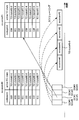
- One DCI may schedule DL data for multiple UEs.
- One DCI may schedule the same DL data in multiple reception occasions.
- the appropriate beam may differ in multiple UEs.
- the plurality of reception occasions may be associated with a plurality of QCL parameters (eg, beam, QCL assumption, TCI state), respectively.
- the DL data in each reception occasion may be transmitted (received) using the corresponding QCL parameters.
- one DCI schedules the same DL data in received occasions (occasions) # 0 to # 3.
- the DL data in occasions # 0, # 1, # 2, and # 3 are transmitted (received) using QCL parameters (QCL) # 0, # 1, # 2, and # 3, respectively.
- the DCI is transmitted to all UEs.
- the DL data in occasion # 0 is transmitted to UEs # 0 and # 1.
- the DL data in Occasion # 1 is transmitted to UE # 2.
- the DL data in Occasion # 2 is transmitted to UE # 3.
- the DL data in occasion # 3 is transmitted to UE # 4.
- DCI may be transmitted in the common search space or may be transmitted in the group common search space.
- the PDCCH monitoring occasion for DCI may vary depending on the QCL used by the UE.
- the UE may select a PDCCH monitoring occasion based on multiple QCL assumptions.
- One DL data may be one code word (CW) or one transport block (TB).
- the same DL data may have the same size (eg, transport block size (TBS)) or may have different sizes.
- the base station does not transmit DL data at the same time using a plurality of beams.
- the RRC parameters in the second and third embodiments are set in the PDSCH setting
- the RRC parameters in the second and third embodiments are set in the PDCCH setting (for example, PDCCH-Config). It may be set in.
- a search space for multicast PDSCH may be specified in the specification, and RRC parameters in the second and third embodiments may be set within the search space settings.
- the UE can appropriately receive at least one of a plurality of DL data in a plurality of reception occasions.
- the UE may set / instruct the association (QCL parameter information) between the reception occasion and the QCL assumption by at least one of the RRC parameter, the MAC CE, and the DCI.
- association QCL parameter information
- a plurality of associations may be set by the RRC parameter, and one of the plurality of associations may be activated by MAC CE.
- the UE may set / instruct the association between the reception occasion and the QCL assumption by any of the following QCL assumption setting / instruction methods 1 and 2.
- a list of reception occasions for DL data may be set for each PDSCH setting.
- a QCL assumption may be set for each reception occasion.
- the QCL assumption may be the index or ID of the corresponding SSB / CSI-RS / TRS / TCI state.
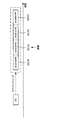
- QCL assumption setting / instruction method 2 For example, as shown in FIG. 2B, a QCL assumption for the first occasion # 0 for DL data may be set for each PDSCH setting. The QCL assumptions for the remaining occasions may be implicitly set (or derived).
- SSB # 0 is set as the QCL assumption for occasion # 0
- the UE will increment the index of the SSB / CSI-RS / TRS / TCI state to assume QCL for the remaining occasions (occasion # 1).
- SSB # 1 as the QCL assumption for the occasion # 2
- SSB # 2 as the QCL assumption for the occasion # 2
- SSB # 3 if SSB # 0 is set as the QCL assumption for occasion # 0, the UE will increment the index of the SSB / CSI-RS / TRS / TCI state to assume QCL for the remaining occasions (occasion # 1).
- SSB # 1 as the QCL assumption for the occasion # 2
- SSB # 2 as the QCL assumption for the occasion # 2
- SSB # 3 As the QCL assumption for the occasion # 3.
- the UE may select one or more reception occasions for DL data based on the QCL assumption.
- the UE may select the QCL assumption according to at least one of the following QCL assumption determination methods 1 to 5.
- the QCL assumption may be an SSB index corresponding to a recent PRACH transmission occasion.
- the QCL assumption may be a DCI QCL assumption.
- the DCI, the DCI that schedules DL data, and the PDCCH monitoring occasion in the common search space may be read interchangeably.
- the QCL assumption may be the best beam in the (recent) L1-RSRP / L1-SINR beam report.
- the QCL assumption may be the best beam identified to the UE by L1-RSRP / L1-SINR beam measurements. This best beam does not have to be reported.
- the QCL assumption may depend on the UE implementation.
- Which of the QCL assumption determination methods 1 to 5 is used may be specified in the specifications, may be set by higher layer signaling, or may be reported as UE capability.
- the UE can appropriately determine the DL data corresponding to the QCL assumption among the plurality of DL data in the plurality of reception occasions.
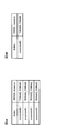
- the UE may set / indicate the association (resource information) between the received occasion and the PDSCH resource by at least one of the RRC parameter, MAC CE and DCI.
- the RRC parameter may set multiple associations and the MAC CE may activate one of the multiple associations.
- the PDSCH resource may be set according to any of the following resource setting / instruction methods 1 and 2.
- a list of reception occasions for DL data may be set for each PDSCH setting.
- a PDSCH resource may be set for each reception occasion.
- the PDSCH resource may be configured by at least one of time domain resource allocation (TDRA) and frequency domain resource allocation (FDRA).
- the PDSCH resource may be set for one receive occasion.
- One reception occasion may be the first reception occasion or the last reception occasion.
- a PDSCH resource for the first reception occasion of DL data may be set.
- the PDSCH resources for the remaining received occasions may be implicitly set (or derived).
- the (FD) resource may be the same as the FD resource of the (m-1) th reception occasion.
- the T offset may be specified by the specification, set by the RRC parameter, or determined by the UE capability report.
- the T offset may be the time from the start of the TD resource of the (m-1) th reception occasion to the start of the TD resource of the mth reception occasion, or the T offset of the (m-1) th reception occasion. It may be the time from the end of the TD resource to the start of the TD resource of the mth reception occasion.
- both TDRA and FDRA of PDSCH are set for each reception occasion.
- the PDSCH resource of each reception occasion can be flexibly set.
- the PDSCH FDRA is set for each reception occasion in the resource setting / instruction method 1.
- the TDRA of the first received occasion is set, the TDRA of the second and subsequent received occasions is not set, and it is derived based on the T offset.
- the frequency domain resource of the first reception occasion is set and used to determine the remaining reception occasions.
- the T offset is the time (interval) from the end of the TD resource of the (m-1) th received occasion to the start of the TD resource of the mth received occasion.
- the relationship between the frequency domain resource of the (m-1) th reception occasion and the FD resource of the mth reception occasion may be determined by the frequency offset F offset.
- the F offset may be specified by the specification, set by the RRC parameter, or determined by the UE capability report.
- the F offset may be an index (number, number of PRBs) from the lowest frequency of the FD resource of the (m-1) th reception occasion to the lowest frequency of the FD resource of the mth reception occasion, or (m). -1) It may be an index (number, interval, number of PRBs) from the highest frequency of the FD resource of the third reception occasion to the lowest frequency of the FD resource of the mth reception occasion.
- the T offset is the time (interval) from the end of the TD resource of the (m-1) th reception occasion to the start of the TD resource of the mth reception occasion.
- the F offset is the PRB index (PRB) from the lowest frequency (first PRB index) of the FD resource of the (m-1) th received occasion to the lowest frequency (first PRB index) of the FD resource of the mth received occasion. Number).
- TDRA / FDRA The value of TDRA / FDRA may follow any of the following definitions 1 and 2.
- the definition of the TDRA / FDRA value of the second and subsequent received occasions may be the same as the definition of the TDRA / FDRA value of the first received occasion.
- each FD resource of occasions # 0 to # 3 may be represented as a PRB index (number of PRBs) from the first PRB index of BWP.
- the TD resource may be expressed as the time from the scheduling DCI (start or end) (for example, at least one of the number of slots, the number of symbols, the time [ms], and the start and length indicator value (SLIV)).
- the definition of the TDRA / FDRA value for the second and subsequent reception occasions may differ from the definition of the TDRA / FDRA value for the first reception occasion.
- the TD / FD resource of the m (m ⁇ 2) th reception occasion may be expressed as a difference (relative value) from the TD / FD resource of the first reception occasion.
- the first PRB index of the FD resource of occasion # 0 is represented as a PRB index from the first PRB index of BWP.
- the first PRB index of each of the FD resources of occasions # 1, # 2, and # 3 is represented as the PRB index from the first PRB index of the FD resource of occasion # 0.
- the TD / FD resource of the m (m ⁇ 2) th received occasion may be expressed as a difference (relative value) from the TD / FD resource of the (m-1) th received occasion.
- the first PRB index of the FD resource of occasion # 0 is represented as a PRB index from the first PRB index of BWP.
- ⁇ PDSCH setting The following at least one parameter for PDSCH may be common to all receiving occasions.
- ⁇ Data scrambling identification information eg dataScramblingIdentityPDSCH
- PDSCH mapping type A for example, dmrs-DownlinkForPDSCH-MappingTypeA
- PDSCH mapping type B for example, dmrs-DownlinkForPDSCH-MappingTypeB
- VRB Virtual Resource Block
- PRB Physical Resource Block
- Interleaver eg vrb-ToPRB-Interleaver
- -PDSCH aggregation factor eg, pdsch-AggregationFactor
- Rate match pattern list for addition and change
- rateMatchPatternToAddModList for example, rateMatchPatternToAddModList
- rateMatchPatternToReleaseList for example, rateMatchPatternToReleaseList
- Rate match pattern group 1 for example, rateMatchPattern
- the parameters common to all reception occasions may be the parameters of the PDSCH settings excluding the FDRA, TDRA, and TCI states.
- the UE can appropriately determine the PDSCH resource of each of the plurality of received occasions.
- the existence of TCI in DCI (existence of TCI in DCI, for example, tci-PresentInDCI) may not be set.
- TCI in DCI may be set for the multicast PDSCH.
- the active TCI status for PDSCH may be set / notified for each received occasion, and one value of a field (eg, TCI field) in the DCI may indicate the TCI status of all received occasions.
- the UE may select a PDSCH reception occasion based on the QCL assumption and use the TCI state indicated by the scheduling DCI to receive the PDSCH DMRS (the PDSCH DMRS is QCLed with the indicated TCI state). You can assume that).
- the beam can be controlled more appropriately. ..
- a plurality of TCI states are activated for each of occasions # 0 to # 3.
- the UE determines QCL # 1 as the QCL assumption and determines the occasion # 1 corresponding to the QCL assumption.
- the PDSCH scheduling DCI indicates TCI status # 1-3.
- occasion # 1 the UE uses the TCI state # 1-3 instructed to receive the DMRS of the PDSCH.
- the UE can appropriately determine the TCI state used for receiving the PDSCH DMRS in the reception occasion.
- Multiple DCIs may each schedule multiple reception occasions.
- the same DL data may be transmitted in each of the plurality of reception occasions.
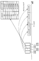
- a DCI using a QCL # x may schedule DL data with a QCL # x'for multiple UEs.
- the DCI detected in the (corresponding) PDCCH monitoring occasion associated with a QCL may schedule DL data in the received occasion associated with that QCL.
- QCL # 0 to # 3 are used for DCI # 0 to # 3 in one search space, respectively.
- the search space is monitored by UEs # 0 through # 4.
- the search space may be a common search space, a group common search space, or a group scheduling search space.
- the UE may determine the PDCCH monitoring occasion to receive the DCI according to the QCL (TCI state) for the PDCCH.
- the monitoring occasion of the PDCCH may differ depending on the QCL for the PDCCH.
- DCI # 0 to # 3 schedule occasions # 0 to # 3, respectively.
- the same DL data is transmitted in occasions # 0 to # 3.
- the DL data in occasions # 0, # 1, # 2, and # 3 are transmitted using QCL # 0, # 1, # 2, and # 3, respectively.
- the DL data in occasion # 0 is transmitted to UEs # 0 and # 1.
- the DL data in Occasion # 1 is transmitted to UE # 2.
- the DL data in Occasion # 2 is transmitted to UE # 3.
- the DL data in occasion # 3 is transmitted to UE # 4.
- PDCCH monitoring may follow at least one of the following PDCCH monitoring methods 1 to 3.
- a plurality of DCIs may be transmitted (received) in the common search space or the group common search space.
- the UE may select a PDCCH monitoring occasion corresponding to the QCL set / indicated for the PDCCH for receiving the DCI.
- DCI # 0 to # 3 are transmitted in one search space.
- DCI # 0 to # 3 are transmitted using QCL # 0 to # 3, respectively.
- DCI # 0 to # 3 are transmitted in PDCCH monitoring occasions (MO) # 0 to # 3, respectively.
- the UE monitors the DCI in a PDCCH monitoring occasion that corresponds to the QCL for the PDCCH.
- a common search space or a group common search space may be set for each of the plurality of QCLs.
- the UE may select a search space corresponding to the QCL set / instructed for the PDCCH for receiving the DCI.
- DCI # 0 to # 3 are transmitted in the search space (SS) # 0 to # 3, respectively.
- DCI # 0 to # 3 are transmitted using QCL # 0 to # 3, respectively.
- the UE monitors the DCI in the search space corresponding to the QCL for the PDCCH.
- a common CORESET or a group common CORESET may be set for each of the plurality of QCLs.
- the UE may select a search space corresponding to the QCL set / instructed for the PDCCH for receiving the DCI.
- DCI # 0 to # 3 are transmitted in CORESET (CR) # 0 to # 3, respectively.
- DCI # 0 to # 3 are transmitted using QCL # 0 to # 3, respectively.
- the UE monitors the DCI in the CORESET corresponding to the QCL for the PDCCH.
- the UE detects DCI by monitoring the common search space or the group scheduling search space set as the group common search space.
- the search space for group scheduling may differ depending on the QCL assumption.
- the group scheduling search space may have different time domain resources (symbols, slots, etc.) depending on the QCL assumption.
- the UE may assume that the same DL data is scheduled in each PDCCH monitoring occasion (DCI in each PDCCH monitoring occasion) in the group scheduling search space.
- the UE may set the search space for group scheduling by higher layer signaling.
- the UE can receive any DL data of occasions # 0 to # 3.
- the UE may follow any of the following decoding operations 1 to 3.
- the UE may decode all of DCI # 0 to # 3, and if it succeeds in decoding any of the DL data of occasions # 0 to # 3, it may transmit (report) HARQ-ACK.
- Decoding operation 2 The UE decodes all of DCI # 0 to # 3, decodes the DL data in one occasion based on the QCL assumption among the occasions # 0 to # 3, and if the decoding of the DL data is successful, HARQ- An ACK may be sent (reported).
- Decryption operation 3 The UE decodes the DCI in one PDCCH monitoring occasion based on the QCL assumption among DCI # 0 to # 3, and decodes the DL data scheduled by the DCI (DL data in the reception occasion based on the QCL assumption). If the DL data is successfully decoded, HARQ-ACK may be transmitted (reported).
- x x'.
- the PDSCH QCL scheduled by the DCI detected in the group scheduling search space may be equal to the DCI QCL.
- the PDSCH QCL scheduled by the DCI detected in the group scheduling search space may be different from the DCI QCL.
- the QCL of each reception occasion of the DL data may be set / notified / indicated by the RRC parameter / MAC CE / DCI.
- the QCL of each reception occasion of the DL data may be determined in the same manner as in the second embodiment.
- the DCI detected in the group scheduling search space may be the following DCI 1 or 2.
- the DCI detected in the group scheduling search space does not have (does not include) a field for DCI level beam indication.
- the TCI field for PDSCH may be 0 bits, or the presence of TCI in DCI (eg, tci-PresentInDCI) may not be set.
- DCI1 may be used.
- the DCI detected in the group scheduling search space has (includes) a field for DCI level beam indication.
- the TCI field for PDSCH may be 3 bits, or the existence of TCI in DCI may be set.
- DCI2 may be in DCI format 1-1.1. According to DCI 1, since the beam can be indicated by DCI, more flexible instruction becomes possible. In addition, it becomes possible to improve the coverage of multicast / broadcast. In addition, high-speed beam control becomes possible for high-speed mobile UEs.
- TCI status setting / activation The PDSCH TCI status list setting / activation may follow at least one of the following TCI status setting / activation methods 1 to 3.
- the PDSCH TCI status list may be set / activated.
- the PDSCH TCI status list may be set / activated for all received occasions.
- the UE may use the same set of active TCI states for PDSCH for all reception occasions. If different QCL parameters are expected for multiple receive occasions, the TCI fields in the multiple scheduling DCIs may point to different code points.
- TCI states # 0 to # 7 are activated for occasions # 0 to # 3.
- the TCI field in DCI # 1 that schedules the DL data for occasion # 1 points to code point 011.
- the UE uses the TCI state # 3, which corresponds to the code point 011 among the activated TCI states # 0 to # 7, to receive the DL data of the occasion # 1.
- the PDSCH TCI status list may be set / activated for each received occasion.
- the TCI states # 0-0 to # 0-7 for occasion # 0 are activated, and the TCI states # 1-0 to # 1-7 for occasion # 1 are activated.
- the TCI field in DCI # 1 that schedules the DL data for occasion # 1 points to code point 011.
- the UE uses the TCI state # 1-3 corresponding to the code point 011 among the TCI states # 1-0 to # 1-7 activated for the occasion # 1 to receive the DL data of the occasion # 1.
- the TCI status list of PDSCH may be set / activated for each DCI / PDCCH / CORESET / search space / PDCCH monitoring occasion.
- TCI states # 0-0 to # 0-7 for PDCCH carrying DCI # 0 are activated, and TCI states # 1-0 to # 1-7 for PDCCH carrying DCI # 1 are activated. Will be done.
- the TCI field in DCI # 1 that schedules the DL data for occasion # 1 points to code point 011.
- the UE performs TCI state # 1-3 corresponding to code point 011 in occasion # 1 scheduled by DCI # 1. Used for receiving DL data.
- the DCI size in each PDCCH monitoring occasion in one group scheduling search space may follow at least one of the following DCI sizes 1 and 2.
- the DCI size within each PDCCH monitoring occasion in one group scheduling search space may be equal.
- blind decoding of the UE can be simplified.
- in-phase addition of the bit before decoding or the received signal before demodulation becomes possible.
- the value of the upper layer parameter (specific parameter, for example, tci-PresentInDCI) for determining the DCI size may be set in common for all PDCCH monitoring occasions.
- the UE may follow any of the following specific parameter determination methods 1 to 4.
- Specific parameter determination method 1 When a specific parameter is set for a certain reception occasion, a specific parameter is always set for another reception occasion. The UE applies specific parameters for the received occasion to the fields in the corresponding DCI.
- the UE sets the PDSCH TCI status list for other reception occasions and the active TCI. Assume that the status is notified (activated).
- the UE also uses certain parameters set for one receive occasion for other receive occasions.
- the UE applies specific parameters for the received occasion to the fields in the corresponding DCI.
- the UE will perform the PDSCH of the first reception occasion. Based on the active TCI state for PDSCH, the active TCI state for PDSCH of the second reception occasion is derived.
- the UE obtains the instruction regarding the specific parameter from the field in the DCI for the received occasion in which the specific parameter is set / notified, and ignores the field related to the specific parameter in the DCI for the received occasion in which the specific parameter is set / notified.
- the UE will perform the DCI for the first receive occasion.
- the TCI state (beam) for PDSCH of the first reception occasion is determined, and the TCI field of DCI for the second reception occasion is ignored.
- Specific parameter determination method 4 The UE does not use the specific parameters set / notified for a given occasion. The UE ignores fields related to specific parameters in each DCI.
- the UE will perform DCI for all receive occasions. Ignore the TCI field of.
- the default TCI state may be used for PDSCH reception for that received occasion.
- the default TCI state may be specified in the specification or set / notified by higher layer signaling.
- the DCI size within each PDCCH monitoring occasion in one group scheduling search space may be different.
- the value of the upper layer parameter (specific parameter, for example, tci-PresentInDCI) for determining the DCI size may be set for each PDCCH monitoring occasion.
- the setting / activation of the TCI status list for PDSCH may be performed for each received occasion or for each DCI.
- the UE can appropriately monitor the DCI that schedules DL data in at least one of a plurality of received occasions.
- the UE may set / indicate the association (resource information) between the received occasion and the PDSCH resource by at least one of the RRC parameter, MAC CE and DCI.
- the RRC parameter may set multiple associations and the MAC CE may activate one of the multiple associations.
- At least one of the following allocations 1 and 2 may be used for a PDSCH having multiple reception occasions.
- a PDSCH resource may be set for each received occasion or DCI.
- a list of reception occasions or DCIs for DL data may be set in one PDSCH setting.
- a PDSCH resource may be set for each received occasion or DCI.
- the PDSCH resource may include at least one of TDRA and FDRA.
- a PDSCH resource may be set for one reception occasion (eg, first or last reception occasion) or one DCCI (eg, first or last DCI).
- one PDSCH resource for one reception occasion (one DCI) for DL data may be set in one PDSCH setting.
- the PDSCH resource may be used to derive the PDSCH resource for the remaining Receive Occasion (DCI) (may be implied).
- DCI Receive Occasion
- the relationship between the TD resource of the (m-1) th receive occasion and the TD resource of the mth receive occasion may be specified in the specification or set by the RRC parameter. It may be reported by UE capability.
- the FD resource of the m-th reception occasion may be the same as the FD resource of the (m-1) th reception occasion.
- TDRA / FDRA may follow any of the definitions 1 and 2 of TDRA / FDRA of the third embodiment.
- the UE is not only scheduled DCI. Since it is necessary to detect the DCI before that, the TD / FD resource of the m-th reception occasion in the present embodiment is the TD / FD resource of the first reception occasion or the (m-1) th reception occasion. It does not have to depend on TD / FD resources.
- the FD resource of each received occasion may be represented as a PRB index from the first PRB index of the BWP.
- the TD resource for each received occasion may be represented as the time (number of slots / number of symbols) from the scheduled DCI (start or end).
- the UE can appropriately determine the resource of the PDSCH having a plurality of reception occasions.
- a first function using at least one of the first to third embodiments and a second function using at least one of the fourth to sixth embodiments may be specified in the specifications.
- the UE may set either the first function or the second function by higher layer signaling.
- the UE may report that it supports at least one of the first and second functions.
- a specific radio network temporarilyally identifier (RNTI) for scheduling at least one PDSCH of the first to sixth embodiments may be defined and set in the UE.
- the DCI that schedules the PDSCH may have a cyclic redundancy check (CRC) that is scrambled by a particular RNTI.
- the PDSCH data may be scrambled by a particular RNTI.
- the UE may decode the DCI or PDSCH assuming scrambling by the specific RNTI.
- the specific RNTI may be set for a plurality of group UEs, or may be set individually for each UE.
- the specific RNTI may be an existing RNTI (for example, RA-RNTI, C-RNTI, etc.).
- the DCI that schedules the PDSCH may have a CRC scrambled by a particular RNTI.
- the PDSCH data may be scrambled by a particular RNTI.
- the UE may decode the DCI or PDSCH assuming scrambling by the specific RNTI.
- the specific RNTI may be set for a plurality of group UEs, or may be set individually for each UE.
- wireless communication system Wireless communication system
- communication is performed using any one of the wireless communication methods according to each of the above-described embodiments of the present disclosure or a combination thereof.
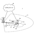
- FIG. 17 is a diagram showing an example of a schematic configuration of a wireless communication system according to an embodiment.
- the wireless communication system 1 may be a system that realizes communication using Long Term Evolution (LTE), 5th generation mobile communication system New Radio (5G NR), etc. specified by Third Generation Partnership Project (3GPP). ..
- the radio communication system 1 may support dual connectivity (Multi-RAT Dual Connectivity (MR-DC)) between a plurality of Radio Access Technologies (RATs).
- MR-DC is dual connectivity between LTE (Evolved Universal Terrestrial Radio Access (E-UTRA)) and NR (E-UTRA-NR Dual Connectivity (EN-DC)), and dual connectivity between NR and LTE (NR-E).
- E-UTRA Evolved Universal Terrestrial Radio Access
- EN-DC E-UTRA-NR Dual Connectivity
- NE-DC -UTRA Dual Connectivity
- the LTE (E-UTRA) base station (eNB) is the master node (Master Node (MN)), and the NR base station (gNB) is the secondary node (Secondary Node (SN)).
- the base station (gNB) of NR is MN
- the base station (eNB) of LTE (E-UTRA) is SN.
- the wireless communication system 1 has dual connectivity between a plurality of base stations in the same RAT (for example, dual connectivity (NR-NR Dual Connectivity (NN-DC)) in which both MN and SN are NR base stations (gNB). )) May be supported.
- a plurality of base stations in the same RAT for example, dual connectivity (NR-NR Dual Connectivity (NN-DC)) in which both MN and SN are NR base stations (gNB). )
- NR-NR Dual Connectivity NR-DC
- gNB NR base stations
- the wireless communication system 1 includes a base station 11 that forms a macro cell C1 having a relatively wide coverage, and a base station 12 (12a-12c) that is arranged in the macro cell C1 and forms a small cell C2 that is narrower than the macro cell C1. You may prepare.
- the user terminal 20 may be located in at least one cell. The arrangement, number, and the like of each cell and the user terminal 20 are not limited to the mode shown in the figure.
- the base stations 11 and 12 are not distinguished, they are collectively referred to as the base station 10.
- the user terminal 20 may be connected to at least one of the plurality of base stations 10.
- the user terminal 20 may use at least one of carrier aggregation (Carrier Aggregation (CA)) and dual connectivity (DC) using a plurality of component carriers (Component Carrier (CC)).
- CA Carrier Aggregation
- DC dual connectivity
- CC Component Carrier
- Each CC may be included in at least one of a first frequency band (Frequency Range 1 (FR1)) and a second frequency band (Frequency Range 2 (FR2)).
- the macro cell C1 may be included in FR1 and the small cell C2 may be included in FR2.
- FR1 may be in a frequency band of 6 GHz or less (sub 6 GHz (sub-6 GHz)), and FR2 may be in a frequency band higher than 24 GHz (above-24 GHz).
- the frequency bands and definitions of FR1 and FR2 are not limited to these, and for example, FR1 may correspond to a frequency band higher than FR2.
- the user terminal 20 may perform communication using at least one of Time Division Duplex (TDD) and Frequency Division Duplex (FDD) in each CC.
- TDD Time Division Duplex
- FDD Frequency Division Duplex
- the plurality of base stations 10 may be connected by wire (for example, optical fiber compliant with Common Public Radio Interface (CPRI), X2 interface, etc.) or wirelessly (for example, NR communication).
- wire for example, optical fiber compliant with Common Public Radio Interface (CPRI), X2 interface, etc.
- NR communication for example, when NR communication is used as a backhaul between base stations 11 and 12, the base station 11 corresponding to the higher-level station is an Integrated Access Backhaul (IAB) donor, and the base station 12 corresponding to a relay station (relay) is IAB. It may be called a node.
- IAB Integrated Access Backhaul
- relay station relay station
- the base station 10 may be connected to the core network 30 via another base station 10 or directly.
- the core network 30 may include at least one such as Evolved Packet Core (EPC), 5G Core Network (5GCN), and Next Generation Core (NGC).
- EPC Evolved Packet Core
- 5GCN 5G Core Network
- NGC Next Generation Core
- the user terminal 20 may be a terminal that supports at least one of communication methods such as LTE, LTE-A, and 5G.
- a wireless access method based on Orthogonal Frequency Division Multiplexing may be used.
- OFDM Orthogonal Frequency Division Multiplexing
- DL Downlink
- UL Uplink
- CP-OFDM Cyclic Prefix OFDM
- DFT-s-OFDM Discrete Fourier Transform Spread OFDM
- OFDMA Orthogonal Frequency Division Multiple. Access
- SC-FDMA Single Carrier Frequency Division Multiple Access
- the wireless access method may be called a waveform.
- another wireless access system for example, another single carrier transmission system, another multi-carrier transmission system
- the UL and DL wireless access systems may be used as the UL and DL wireless access systems.
- downlink shared channels Physical Downlink Shared Channel (PDSCH)
- broadcast channels Physical Broadcast Channel (PBCH)
- downlink control channels Physical Downlink Control
- Channel PDCCH
- the uplink shared channel Physical Uplink Shared Channel (PUSCH)
- the uplink control channel Physical Uplink Control Channel (PUCCH)
- the random access channel shared by each user terminal 20 are used.
- Physical Random Access Channel (PRACH) Physical Random Access Channel or the like may be used.
- User data, upper layer control information, System Information Block (SIB), etc. are transmitted by PDSCH.
- User data, upper layer control information, and the like may be transmitted by the PUSCH.
- the Master Information Block (MIB) may be transmitted by the PBCH.
- Lower layer control information may be transmitted by PDCCH.
- the lower layer control information may include, for example, downlink control information (Downlink Control Information (DCI)) including scheduling information of at least one of PDSCH and PUSCH.
- DCI Downlink Control Information
- the DCI that schedules PDSCH may be called DL assignment, DL DCI, etc.
- the DCI that schedules PUSCH may be called UL grant, UL DCI, etc.
- the PDSCH may be read as DL data
- the PUSCH may be read as UL data.
- a control resource set (COntrol REsource SET (CORESET)) and a search space (search space) may be used for PDCCH detection.
- CORESET corresponds to a resource that searches for DCI.
- the search space corresponds to the search area and search method of PDCCH candidates (PDCCH candidates).
- One CORESET may be associated with one or more search spaces. The UE may monitor the CORESET associated with a search space based on the search space settings.
- One search space may correspond to PDCCH candidates corresponding to one or more aggregation levels.
- One or more search spaces may be referred to as a search space set.
- the "search space”, “search space set”, “search space setting”, “search space set setting”, “CORESET”, “CORESET setting”, etc. of the present disclosure may be read as each other.
- channel state information (Channel State Information (CSI)
- delivery confirmation information for example, it may be called Hybrid Automatic Repeat reQuest ACKnowledgement (HARQ-ACK), ACK / NACK, etc.
- scheduling request (Scheduling Request ( Uplink Control Information (UCI) including at least one of SR))
- the PRACH may transmit a random access preamble to establish a connection with the cell.
- downlinks, uplinks, etc. may be expressed without “links”. Further, it may be expressed without adding "Physical" at the beginning of various channels.
- a synchronization signal (Synchronization Signal (SS)), a downlink reference signal (Downlink Reference Signal (DL-RS)), and the like may be transmitted.
- the DL-RS includes a cell-specific reference signal (Cell-specific Reference Signal (CRS)), a channel state information reference signal (Channel State Information Reference Signal (CSI-RS)), and a demodulation reference signal (DeModulation).
- CRS Cell-specific Reference Signal
- CSI-RS Channel State Information Reference Signal
- DeModulation Demodulation reference signal
- Reference Signal (DMRS)), positioning reference signal (Positioning Reference Signal (PRS)), phase tracking reference signal (Phase Tracking Reference Signal (PTRS)), and the like may be transmitted.
- PRS Positioning Reference Signal
- PTRS Phase Tracking Reference Signal
- the synchronization signal may be, for example, at least one of a primary synchronization signal (Primary Synchronization Signal (PSS)) and a secondary synchronization signal (Secondary Synchronization Signal (SSS)).
- PSS Primary Synchronization Signal
- SSS Secondary Synchronization Signal
- the signal block including SS (PSS, SSS) and PBCH (and DMRS for PBCH) may be referred to as SS / PBCH block, SS Block (SSB) and the like.
- SS, SSB and the like may also be called a reference signal.
- a measurement reference signal Sounding Reference Signal (SRS)
- a demodulation reference signal DMRS
- UL-RS Uplink Reference Signal
- UE-specific Reference Signal UE-specific Reference Signal
- FIG. 18 is a diagram showing an example of the configuration of the base station according to the embodiment.
- the base station 10 includes a control unit 110, a transmission / reception unit 120, a transmission / reception antenna 130, and a transmission line interface 140.
- the control unit 110, the transmission / reception unit 120, the transmission / reception antenna 130, and the transmission line interface 140 may each be provided with one or more.
- this example mainly shows the functional blocks of the feature portion in the present embodiment, and it may be assumed that the base station 10 also has other functional blocks necessary for wireless communication. A part of the processing of each part described below may be omitted.
- the control unit 110 controls the entire base station 10.
- the control unit 110 can be composed of a controller, a control circuit, and the like described based on the common recognition in the technical field according to the present disclosure.
- the control unit 110 may control signal generation, scheduling (for example, resource allocation, mapping) and the like.
- the control unit 110 may control transmission / reception, measurement, and the like using the transmission / reception unit 120, the transmission / reception antenna 130, and the transmission line interface 140.
- the control unit 110 may generate data to be transmitted as a signal, control information, a sequence, and the like, and transfer the data to the transmission / reception unit 120.
- the control unit 110 may perform call processing (setting, release, etc.) of the communication channel, state management of the base station 10, management of radio resources, and the like.
- the transmission / reception unit 120 may include a baseband unit 121, a Radio Frequency (RF) unit 122, and a measurement unit 123.
- the baseband unit 121 may include a transmission processing unit 1211 and a reception processing unit 1212.
- the transmitter / receiver 120 includes a transmitter / receiver, an RF circuit, a baseband circuit, a filter, a phase shifter, a measurement circuit, a transmitter / receiver circuit, and the like, which are described based on common recognition in the technical fields according to the present disclosure. be able to.
- the transmission / reception unit 120 may be configured as an integrated transmission / reception unit, or may be composed of a transmission unit and a reception unit.
- the transmission unit may be composed of a transmission processing unit 1211 and an RF unit 122.
- the receiving unit may be composed of a receiving processing unit 1212, an RF unit 122, and a measuring unit 123.
- the transmitting / receiving antenna 130 can be composed of an antenna described based on common recognition in the technical field according to the present disclosure, for example, an array antenna.
- the transmission / reception unit 120 may transmit the above-mentioned downlink channel, synchronization signal, downlink reference signal, and the like.
- the transmission / reception unit 120 may receive the above-mentioned uplink channel, uplink reference signal, and the like.
- the transmission / reception unit 120 may form at least one of a transmission beam and a reception beam by using digital beamforming (for example, precoding), analog beamforming (for example, phase rotation), and the like.
- digital beamforming for example, precoding
- analog beamforming for example, phase rotation
- the transmission / reception unit 120 processes, for example, Packet Data Convergence Protocol (PDCP) layer processing and Radio Link Control (RLC) layer processing (for example, RLC) for data, control information, etc. acquired from control unit 110.
- PDCP Packet Data Convergence Protocol
- RLC Radio Link Control
- MAC Medium Access Control
- HARQ retransmission control for example, HARQ retransmission control
- the transmission / reception unit 120 performs channel coding (may include error correction coding), modulation, mapping, filtering, and discrete Fourier transform (Discrete Fourier Transform (DFT)) for the bit string to be transmitted.
- the base band signal may be output by performing processing (if necessary), inverse fast Fourier transform (IFFT) processing, precoding, digital-analog conversion, and other transmission processing.
- IFFT inverse fast Fourier transform
- the transmission / reception unit 120 may perform modulation, filtering, amplification, etc. on the baseband signal to the radio frequency band, and transmit the signal in the radio frequency band via the transmission / reception antenna 130. ..
- the transmission / reception unit 120 may perform amplification, filtering, demodulation to a baseband signal, or the like on the signal in the radio frequency band received by the transmission / reception antenna 130.
- the transmission / reception unit 120 (reception processing unit 1212) performs analog-digital conversion, fast Fourier transform (FFT) processing, and inverse discrete Fourier transform (IDFT) on the acquired baseband signal. )) Processing (if necessary), filtering, decoding, demodulation, decoding (may include error correction decoding), MAC layer processing, RLC layer processing, PDCP layer processing, and other reception processing are applied. User data and the like may be acquired.
- FFT fast Fourier transform
- IDFT inverse discrete Fourier transform
- the transmission / reception unit 120 may perform measurement on the received signal.
- the measuring unit 123 may perform Radio Resource Management (RRM) measurement, Channel State Information (CSI) measurement, or the like based on the received signal.
- the measuring unit 123 has received power (for example, Reference Signal Received Power (RSRP)) and reception quality (for example, Reference Signal Received Quality (RSRQ), Signal to Interference plus Noise Ratio (SINR), Signal to Noise Ratio (SNR)).
- RSRP Reference Signal Received Power
- RSSQ Reference Signal Received Quality
- SINR Signal to Noise Ratio
- Signal strength for example, Received Signal Strength Indicator (RSSI)
- propagation path information for example, CSI
- the measurement result may be output to the control unit 110.
- the transmission line interface 140 transmits / receives signals (backhaul signaling) to / from a device included in the core network 30, another base station 10 and the like, and provides user data (user plane data) and control plane for the user terminal 20. Data or the like may be acquired or transmitted.
- the transmission unit and the reception unit of the base station 10 in the present disclosure may be composed of at least one of the transmission / reception unit 120, the transmission / reception antenna 130, and the transmission line interface 140.
- the transmission / reception unit 120 may transmit downlink control information.
- the control unit 110 may use the reception occasion corresponding to the pseudo-collocation (QCL) parameter among the plurality of reception occasions for data transmission.
- the downlink control information may schedule the plurality of reception occasions.
- the data may be transmitted in each of the plurality of reception occasions.
- the transmission / reception unit 120 may transmit a plurality of downlink control information.
- the control unit 110 may use the reception occasion corresponding to the pseudo-collocation (QCL) parameter among the plurality of reception occasions for data transmission.
- the plurality of downlink control information may schedule the plurality of reception occasions, respectively.
- the data may be transmitted in each of the plurality of reception occasions.
- FIG. 19 is a diagram showing an example of the configuration of the user terminal according to the embodiment.
- the user terminal 20 includes a control unit 210, a transmission / reception unit 220, and a transmission / reception antenna 230.
- the control unit 210, the transmission / reception unit 220, and the transmission / reception antenna 230 may each be provided with one or more.
- this example mainly shows the functional blocks of the feature portion in the present embodiment, and it may be assumed that the user terminal 20 also has other functional blocks necessary for wireless communication. A part of the processing of each part described below may be omitted.
- the control unit 210 controls the entire user terminal 20.
- the control unit 210 can be composed of a controller, a control circuit, and the like described based on the common recognition in the technical field according to the present disclosure.
- the control unit 210 may control signal generation, mapping, and the like.
- the control unit 210 may control transmission / reception, measurement, and the like using the transmission / reception unit 220 and the transmission / reception antenna 230.
- the control unit 210 may generate data to be transmitted as a signal, control information, a sequence, and the like, and transfer the data to the transmission / reception unit 220.
- the transmission / reception unit 220 may include a baseband unit 221 and an RF unit 222, and a measurement unit 223.
- the baseband unit 221 may include a transmission processing unit 2211 and a reception processing unit 2212.
- the transmitter / receiver 220 can be composed of a transmitter / receiver, an RF circuit, a baseband circuit, a filter, a phase shifter, a measurement circuit, a transmitter / receiver circuit, and the like, which are described based on the common recognition in the technical field according to the present disclosure.
- the transmission / reception unit 220 may be configured as an integrated transmission / reception unit, or may be composed of a transmission unit and a reception unit.
- the transmission unit may be composed of a transmission processing unit 2211 and an RF unit 222.
- the receiving unit may be composed of a receiving processing unit 2212, an RF unit 222, and a measuring unit 223.
- the transmitting / receiving antenna 230 can be composed of an antenna described based on common recognition in the technical field according to the present disclosure, for example, an array antenna.
- the transmission / reception unit 220 may receive the above-mentioned downlink channel, synchronization signal, downlink reference signal, and the like.
- the transmission / reception unit 220 may transmit the above-mentioned uplink channel, uplink reference signal, and the like.
- the transmission / reception unit 220 may form at least one of a transmission beam and a reception beam by using digital beamforming (for example, precoding), analog beamforming (for example, phase rotation), and the like.
- digital beamforming for example, precoding
- analog beamforming for example, phase rotation
- the transmission / reception unit 220 (transmission processing unit 2211) performs PDCP layer processing, RLC layer processing (for example, RLC retransmission control), and MAC layer processing (for example, for data, control information, etc. acquired from the control unit 210). , HARQ retransmission control), etc., to generate a bit string to be transmitted.
- RLC layer processing for example, RLC retransmission control
- MAC layer processing for example, for data, control information, etc. acquired from the control unit 210.
- HARQ retransmission control HARQ retransmission control
- the transmission / reception unit 220 (transmission processing unit 2211) performs channel coding (may include error correction coding), modulation, mapping, filtering processing, DFT processing (if necessary), and IFFT processing for the bit string to be transmitted. , Precoding, digital-to-analog conversion, and other transmission processing may be performed to output the baseband signal.
- Whether or not to apply the DFT process may be based on the transform precoding setting.
- the transmission / reception unit 220 transmits the channel using the DFT-s-OFDM waveform.
- the DFT process may be performed as the transmission process, and if not, the DFT process may not be performed as the transmission process.
- the transmission / reception unit 220 may perform modulation, filtering, amplification, etc. on the baseband signal to the radio frequency band, and transmit the signal in the radio frequency band via the transmission / reception antenna 230. ..
- the transmission / reception unit 220 may perform amplification, filtering, demodulation to a baseband signal, or the like on the signal in the radio frequency band received by the transmission / reception antenna 230.
- the transmission / reception unit 220 (reception processing unit 2212) performs analog-to-digital conversion, FFT processing, IDFT processing (if necessary), filtering processing, demapping, demodulation, and decoding (error correction) for the acquired baseband signal. Decoding may be included), MAC layer processing, RLC layer processing, PDCP layer processing, and other reception processing may be applied to acquire user data and the like.
- the transmission / reception unit 220 may perform measurement on the received signal.
- the measuring unit 223 may perform RRM measurement, CSI measurement, or the like based on the received signal.
- the measuring unit 223 may measure received power (for example, RSRP), reception quality (for example, RSRQ, SINR, SNR), signal strength (for example, RSSI), propagation path information (for example, CSI), and the like.
- the measurement result may be output to the control unit 210.
- the transmitting unit and the receiving unit of the user terminal 20 in the present disclosure may be composed of at least one of the transmitting / receiving unit 220 and the transmitting / receiving antenna 230.
- the transmission / reception unit 220 may receive downlink control information.
- the control unit 210 may use the reception occasion corresponding to the pseudo collocation (QCL) parameter among the plurality of reception occasions for data reception.
- the downlink control information may schedule the plurality of reception occasions.
- the data may be transmitted in each of the plurality of reception occasions.
- the transmission / reception unit 220 may receive QCL parameter information indicating a plurality of QCL parameters associated with each of the plurality of reception occasions, or QCL parameters associated with one of the plurality of reception occasions.
- the control unit 210 may determine the QCL parameter to be used based on the QCL parameter information.
- the transmission / reception unit 220 may receive resource information indicating a plurality of resources associated with each of the plurality of reception occasions, or a resource associated with one of the plurality of reception occasions.
- the control unit 210 may determine the resource of the data based on the resource information.
- the control unit 210 may use the transmission setting instruction (TCI) state instructed by the downlink control information for receiving the data.
- TCI transmission setting instruction
- the transmission / reception unit 220 may receive one downlink control information of a plurality of downlink control information.
- the control unit 210 may use the reception occasion corresponding to the pseudo-collocation (QCL) parameter among the plurality of reception occasions for data reception.
- the plurality of downlink control information may schedule the plurality of reception occasions, respectively.
- the data may be transmitted in each of the plurality of reception occasions.
- the plurality of downlink control information may be transmitted in a plurality of physical downlink control channel monitoring occasions, a plurality of search spaces, or a plurality of control resource sets, respectively.
- the control unit 210 obtains one of the QCL parameters used for receiving the downlink control information, the QCL parameters corresponding to the reception occasion, and the QCL parameters indicated by the downlink control information as the data. It may be used for receiving.
- the transmission / reception unit 220 may receive resource information indicating a plurality of resources associated with each of the plurality of reception occasions, or a resource associated with one of the plurality of reception occasions.
- the control unit 210 may determine the resource of the data based on the resource information.
- each functional block may be realized by using one device that is physically or logically connected, or directly or indirectly (for example, by two or more devices that are physically or logically separated). , Wired, wireless, etc.) and may be realized using these plurality of devices.
- the functional block may be realized by combining the software with the one device or the plurality of devices.
- the functions include judgment, decision, judgment, calculation, calculation, processing, derivation, investigation, search, confirmation, reception, transmission, output, access, solution, selection, selection, establishment, comparison, assumption, expectation, and deemed. , Broadcasting, notifying, communicating, forwarding, configuring, reconfiguring, allocating, mapping, assigning, etc.
- a functional block (constituent unit) for functioning transmission may be referred to as a transmitting unit (transmitting unit), a transmitter (transmitter), or the like.
- the method of realizing each of them is not particularly limited.
- the base station, user terminal, and the like in one embodiment of the present disclosure may function as a computer that processes the wireless communication method of the present disclosure.
- FIG. 20 is a diagram showing an example of the hardware configuration of the base station and the user terminal according to the embodiment.
- the base station 10 and the user terminal 20 described above may be physically configured as a computer device including a processor 1001, a memory 1002, a storage 1003, a communication device 1004, an input device 1005, an output device 1006, a bus 1007, and the like. ..
- the hardware configuration of the base station 10 and the user terminal 20 may be configured to include one or more of the devices shown in the figure, or may be configured not to include some of the devices.
- processor 1001 may be a plurality of processors. Further, the processing may be executed by one processor, or the processing may be executed simultaneously, sequentially, or by using other methods by two or more processors.
- the processor 1001 may be mounted by one or more chips.
- the processor 1001 For each function of the base station 10 and the user terminal 20, for example, by loading predetermined software (program) on hardware such as the processor 1001 and the memory 1002, the processor 1001 performs an operation and communicates via the communication device 1004. It is realized by controlling at least one of reading and writing of data in the memory 1002 and the storage 1003.
- predetermined software program
- Processor 1001 operates, for example, an operating system to control the entire computer.
- the processor 1001 may be configured by a central processing unit (CPU) including an interface with peripheral devices, a control device, an arithmetic unit, a register, and the like.
- CPU central processing unit
- control unit 110 210
- transmission / reception unit 120 220
- the like may be realized by the processor 1001.
- the processor 1001 reads a program (program code), a software module, data, etc. from at least one of the storage 1003 and the communication device 1004 into the memory 1002, and executes various processes according to these.
- a program program code
- the control unit 110 may be realized by a control program stored in the memory 1002 and operating in the processor 1001, and may be realized in the same manner for other functional blocks.
- the memory 1002 is a computer-readable recording medium, for example, at least a Read Only Memory (ROM), an Erasable Programmable ROM (EPROM), an Electrically EPROM (EEPROM), a Random Access Memory (RAM), or any other suitable storage medium. It may be composed of one.
- the memory 1002 may be referred to as a register, a cache, a main memory (main storage device), or the like.
- the memory 1002 can store a program (program code), a software module, or the like that can be executed to implement the wireless communication method according to the embodiment of the present disclosure.
- the storage 1003 is a computer-readable recording medium, and is, for example, a flexible disk, a floppy (registered trademark) disk, an optical magnetic disk (for example, a compact disc (Compact Disc ROM (CD-ROM)), a digital versatile disk, etc.). At least one of Blu-ray® disks, removable disks, optical disc drives, smart cards, flash memory devices (eg cards, sticks, key drives), magnetic stripes, databases, servers, and other suitable storage media. It may be composed of.
- the storage 1003 may be referred to as an auxiliary storage device.
- the communication device 1004 is hardware (transmission / reception device) for communicating between computers via at least one of a wired network and a wireless network, and is also referred to as, for example, a network device, a network controller, a network card, a communication module, or the like.
- the communication device 1004 includes, for example, a high frequency switch, a duplexer, a filter, a frequency synthesizer, etc. in order to realize at least one of frequency division duplex (Frequency Division Duplex (FDD)) and time division duplex (Time Division Duplex (TDD)). May be configured to include.
- FDD Frequency Division Duplex
- TDD Time Division Duplex
- the transmission / reception unit 120 (220), the transmission / reception antenna 130 (230), and the like described above may be realized by the communication device 1004.
- the transmission / reception unit 120 (220) may be physically or logically separated from the transmission unit 120a (220a) and the reception unit 120b (220b).
- the input device 1005 is an input device (for example, a keyboard, a mouse, a microphone, a switch, a button, a sensor, etc.) that receives an input from the outside.
- the output device 1006 is an output device (for example, a display, a speaker, a Light Emitting Diode (LED) lamp, etc.) that outputs to the outside.
- the input device 1005 and the output device 1006 may have an integrated configuration (for example, a touch panel).
- each device such as the processor 1001 and the memory 1002 is connected by the bus 1007 for communicating information.
- the bus 1007 may be configured by using a single bus, or may be configured by using a different bus for each device.
- the base station 10 and the user terminal 20 include a microprocessor, a digital signal processor (Digital Signal Processor (DSP)), an Application Specific Integrated Circuit (ASIC), a Programmable Logic Device (PLD), a Field Programmable Gate Array (FPGA), and the like. It may be configured to include hardware, and a part or all of each functional block may be realized by using the hardware. For example, processor 1001 may be implemented using at least one of these hardware.
- DSP Digital Signal Processor
- ASIC Application Specific Integrated Circuit
- PLD Programmable Logic Device
- FPGA Field Programmable Gate Array
- the wireless frame may be composed of one or more periods (frames) in the time domain.
- Each of the one or more periods (frames) constituting the wireless frame may be referred to as a subframe.
- the subframe may be composed of one or more slots in the time domain.
- the subframe may have a fixed time length (eg, 1 ms) that is independent of numerology.
- the numerology may be a communication parameter applied to at least one of transmission and reception of a signal or channel.
- Numerology includes, for example, subcarrier spacing (SubCarrier Spacing (SCS)), bandwidth, symbol length, cyclic prefix length, transmission time interval (Transmission Time Interval (TTI)), number of symbols per TTI, and wireless frame configuration.
- SCS subcarrier Spacing
- TTI Transmission Time Interval
- a specific filtering process performed by the transmitter / receiver in the frequency domain, a specific windowing process performed by the transmitter / receiver in the time domain, and the like may be indicated.
- the slot may be composed of one or more symbols in the time domain (Orthogonal Frequency Division Multiple Access (OFDMA) symbol, Single Carrier Frequency Division Multiple Access (SC-FDMA) symbol, etc.).
- OFDMA Orthogonal Frequency Division Multiple Access
- SC-FDMA Single Carrier Frequency Division Multiple Access
- the slot may be a time unit based on numerology.
- the slot may include a plurality of mini slots. Each minislot may consist of one or more symbols in the time domain. Further, the mini slot may be referred to as a sub slot. A minislot may consist of a smaller number of symbols than the slot.
- a PDSCH (or PUSCH) transmitted in a time unit larger than the minislot may be referred to as a PDSCH (PUSCH) mapping type A.
- the PDSCH (or PUSCH) transmitted using the minislot may be referred to as PDSCH (PUSCH) mapping type B.
- the wireless frame, subframe, slot, minislot and symbol all represent the time unit when transmitting a signal.
- the radio frame, subframe, slot, minislot and symbol may have different names corresponding to each.
- the time units such as frames, subframes, slots, minislots, and symbols in the present disclosure may be read as each other.
- one subframe may be called TTI
- a plurality of consecutive subframes may be called TTI
- one slot or one minislot may be called TTI. That is, at least one of the subframe and TTI may be a subframe (1 ms) in existing LTE, a period shorter than 1 ms (eg, 1-13 symbols), or a period longer than 1 ms. It may be.
- the unit representing TTI may be called a slot, a mini slot, or the like instead of a subframe.
- TTI refers to, for example, the minimum time unit of scheduling in wireless communication.
- the base station schedules each user terminal to allocate radio resources (frequency bandwidth that can be used in each user terminal, transmission power, etc.) in TTI units.
- the definition of TTI is not limited to this.
- the TTI may be a transmission time unit such as a channel-encoded data packet (transport block), a code block, or a code word, or may be a processing unit such as scheduling or link adaptation.
- the time interval for example, the number of symbols
- the transport block, code block, code word, etc. may be shorter than the TTI.
- one or more TTIs may be the minimum time unit for scheduling. Further, the number of slots (number of mini-slots) constituting the minimum time unit of the scheduling may be controlled.
- a TTI having a time length of 1 ms may be referred to as a normal TTI (TTI in 3GPP Rel. 8-12), a normal TTI, a long TTI, a normal subframe, a normal subframe, a long subframe, a slot, or the like.
- a TTI shorter than a normal TTI may be referred to as a shortened TTI, a short TTI, a partial TTI (partial or fractional TTI), a shortened subframe, a short subframe, a minislot, a subslot, a slot, or the like.
- the long TTI (for example, normal TTI, subframe, etc.) may be read as a TTI having a time length of more than 1 ms, and the short TTI (for example, shortened TTI, etc.) is less than the TTI length of the long TTI and 1 ms. It may be read as a TTI having the above TTI length.
- a resource block is a resource allocation unit in the time domain and the frequency domain, and may include one or a plurality of continuous subcarriers in the frequency domain.
- the number of subcarriers contained in the RB may be the same regardless of the numerology, and may be, for example, 12.
- the number of subcarriers contained in the RB may be determined based on numerology.
- the RB may include one or more symbols in the time domain, and may have a length of 1 slot, 1 mini slot, 1 subframe or 1 TTI.
- Each 1TTI, 1 subframe, etc. may be composed of one or a plurality of resource blocks.
- One or more RBs are a physical resource block (Physical RB (PRB)), a sub-carrier group (Sub-Carrier Group (SCG)), a resource element group (Resource Element Group (REG)), a PRB pair, and an RB. It may be called a pair or the like.
- Physical RB Physical RB (PRB)
- SCG sub-carrier Group
- REG resource element group
- the resource block may be composed of one or a plurality of resource elements (Resource Element (RE)).
- RE Resource Element
- 1RE may be a radio resource area of 1 subcarrier and 1 symbol.
- Bandwidth Part (which may also be called partial bandwidth, etc.) represents a subset of consecutive common resource blocks (RBs) for a numerology in a carrier. May be good.
- the common RB may be specified by the index of the RB with respect to the common reference point of the carrier.
- PRBs may be defined in a BWP and numbered within that BWP.
- the BWP may include UL BWP (BWP for UL) and DL BWP (BWP for DL).
- BWP UL BWP
- BWP for DL DL BWP
- One or more BWPs may be set in one carrier for the UE.
- At least one of the configured BWPs may be active, and the UE may not expect to send or receive a given signal / channel outside the active BWP.
- “cell”, “carrier” and the like in this disclosure may be read as “BWP”.
- the above-mentioned structures such as wireless frames, subframes, slots, mini slots, and symbols are merely examples.
- the number of subframes contained in a wireless frame the number of slots per subframe or wireless frame, the number of minislots contained in a slot, the number of symbols and RBs contained in a slot or minislot, and included in the RB.
- the number of subcarriers, the number of symbols in the TTI, the symbol length, the cyclic prefix (CP) length, and other configurations can be changed in various ways.
- the information, parameters, etc. described in the present disclosure may be expressed using absolute values, relative values from predetermined values, or using other corresponding information. It may be represented. For example, radio resources may be indicated by a given index.
- the information, signals, etc. described in this disclosure may be represented using any of a variety of different techniques.
- data, instructions, commands, information, signals, bits, symbols, chips, etc. that may be referred to throughout the above description are voltages, currents, electromagnetic waves, magnetic fields or magnetic particles, light fields or photons, or any of these. It may be represented by a combination of.
- information, signals, etc. can be output from the upper layer to the lower layer and from the lower layer to at least one of the upper layers.
- Information, signals, etc. may be input / output via a plurality of network nodes.
- Input / output information, signals, etc. may be stored in a specific location (for example, memory) or may be managed using a management table. Input / output information, signals, etc. can be overwritten, updated, or added. The output information, signals, etc. may be deleted. The input information, signals, etc. may be transmitted to other devices.
- the notification of information is not limited to the mode / embodiment described in the present disclosure, and may be performed by using other methods.
- the notification of information in the present disclosure includes physical layer signaling (for example, downlink control information (DCI)), uplink control information (Uplink Control Information (UCI))), and higher layer signaling (for example, Radio Resource Control). (RRC) signaling, broadcast information (Master Information Block (MIB), System Information Block (SIB), etc.), Medium Access Control (MAC) signaling), other signals or combinations thereof May be carried out by.
- DCI downlink control information
- UCI Uplink Control Information
- RRC Radio Resource Control
- MIB Master Information Block
- SIB System Information Block
- MAC Medium Access Control
- the physical layer signaling may be referred to as Layer 1 / Layer 2 (L1 / L2) control information (L1 / L2 control signal), L1 control information (L1 control signal), and the like.
- the RRC signaling may be called an RRC message, and may be, for example, an RRC connection setup (RRC Connection Setup) message, an RRC connection reconfiguration (RRC Connection Reconfiguration) message, or the like.
- MAC signaling may be notified using, for example, a MAC control element (MAC Control Element (CE)).
- CE MAC Control Element
- the notification of predetermined information is not limited to the explicit notification, but implicitly (for example, by not notifying the predetermined information or another information). May be done (by notification of).
- the determination may be made by a value represented by 1 bit (0 or 1), or by a boolean value represented by true or false. , May be done by numerical comparison (eg, comparison with a given value).
- Software whether referred to as software, firmware, middleware, microcode, hardware description language, or other names, is an instruction, instruction set, code, code segment, program code, program, subprogram, software module.
- Applications, software applications, software packages, routines, subroutines, objects, executable files, execution threads, procedures, functions, etc. should be broadly interpreted.
- software, instructions, information, etc. may be transmitted and received via a transmission medium.
- a transmission medium For example, a website where software uses at least one of wired technology (coaxial cable, fiber optic cable, twisted pair, digital subscriber line (DSL), etc.) and wireless technology (infrared, microwave, etc.).
- wired technology coaxial cable, fiber optic cable, twisted pair, digital subscriber line (DSL), etc.
- wireless technology infrared, microwave, etc.
- the terms “system” and “network” used in this disclosure may be used interchangeably.
- the “network” may mean a device (eg, a base station) included in the network.
- precoding "precoding weight”
- QCL Quality of Co-Co-Location
- TCI state Transmission Configuration Indication state
- space "Spatial relation”, “spatial domain filter”, “transmission power”, “phase rotation”, "antenna port”, “antenna port group”, “layer”, “number of layers”
- Terms such as “rank”, “resource”, “resource set”, “resource group”, “beam”, “beam width”, “beam angle”, "antenna”, “antenna element", “panel” are compatible.
- Base station BS
- radio base station fixed station
- NodeB NodeB
- eNB eNodeB
- gNB gNodeB
- Access point "Transmission point (Transmission Point (TP))
- RP Reception point
- TRP Transmission / Reception Point
- Panel , "Cell”, “sector”, “cell group”, “carrier”, “component carrier” and the like
- Base stations are sometimes referred to by terms such as macrocells, small cells, femtocells, and picocells.
- the base station can accommodate one or more (for example, three) cells.
- a base station accommodates multiple cells, the entire coverage area of the base station can be divided into multiple smaller areas, each smaller area being a base station subsystem (eg, a small indoor base station (Remote Radio)).
- Communication services can also be provided by Head (RRH))).
- RRH Head
- the term "cell” or “sector” refers to part or all of the coverage area of at least one of the base stations and base station subsystems that provide communication services in this coverage.
- MS mobile station
- UE user equipment
- terminal terminal
- Mobile stations include subscriber stations, mobile units, subscriber units, wireless units, remote units, mobile devices, wireless devices, wireless communication devices, remote devices, mobile subscriber stations, access terminals, mobile terminals, wireless terminals, remote terminals. , Handset, user agent, mobile client, client or some other suitable term.
- At least one of the base station and the mobile station may be called a transmitting device, a receiving device, a wireless communication device, or the like.
- At least one of the base station and the mobile station may be a device mounted on the mobile body, the mobile body itself, or the like.
- the moving body may be a vehicle (for example, a car, an airplane, etc.), an unmanned moving body (for example, a drone, an autonomous vehicle, etc.), or a robot (manned or unmanned type). ) May be.
- at least one of the base station and the mobile station includes a device that does not necessarily move during communication operation.
- at least one of the base station and the mobile station may be an Internet of Things (IoT) device such as a sensor.
- IoT Internet of Things
- the base station in the present disclosure may be read by the user terminal.
- the communication between the base station and the user terminal is replaced with the communication between a plurality of user terminals (for example, it may be called Device-to-Device (D2D), Vehicle-to-Everything (V2X), etc.).
- D2D Device-to-Device
- V2X Vehicle-to-Everything
- Each aspect / embodiment of the present disclosure may be applied to the configuration.
- the user terminal 20 may have the function of the base station 10 described above.
- words such as "up” and “down” may be read as words corresponding to communication between terminals (for example, "side”).
- the upstream channel, the downstream channel, and the like may be read as a side channel.
- the user terminal in the present disclosure may be read as a base station.
- the base station 10 may have the functions of the user terminal 20 described above.
- the operation performed by the base station may be performed by its upper node (upper node) in some cases.
- various operations performed for communication with a terminal are performed by the base station and one or more network nodes other than the base station (for example,).
- Mobility Management Entity (MME), Serving-Gateway (S-GW), etc. can be considered, but it is not limited to these), or it is clear that it can be performed by a combination thereof.
- each aspect / embodiment described in the present disclosure may be used alone, in combination, or switched with execution. Further, the order of the processing procedures, sequences, flowcharts, etc. of each aspect / embodiment described in the present disclosure may be changed as long as there is no contradiction. For example, the methods described in the present disclosure present elements of various steps using exemplary order, and are not limited to the particular order presented.
- LTE Long Term Evolution
- LTE-A LTE-Advanced
- SUPER 3G IMT-Advanced
- 4G 4th generation mobile communication system
- 5G 5th generation mobile communication system
- 6G 6th generation mobile communication system
- xG xG (xG (x is, for example, integer, fraction)
- Future Radio Access FAA
- RAT New -Radio Access Technology
- NR New Radio
- NX New radio access
- FX Future generation radio access
- GSM registered trademark
- CDMA2000 Code Division Multiple Access
- UMB Ultra Mobile Broadband
- LTE 802.11 Wi-Fi®
- LTE 802.16 WiMAX®
- LTE 802.20 Ultra-WideBand (UWB), Bluetooth®, and other suitable radios. It may be applied to a system using a communication method, a next-generation system extended based on these, and the like.
- UMB Ultra-WideBand
- references to elements using designations such as “first”, “second”, etc. as used in this disclosure does not generally limit the quantity or order of those elements. These designations can be used in the present disclosure as a convenient way to distinguish between two or more elements. Thus, references to the first and second elements do not mean that only two elements can be adopted or that the first element must somehow precede the second element.
- determining used in this disclosure may include a wide variety of actions.
- judgment (decision) means judgment (judging), calculation (calculating), calculation (computing), processing (processing), derivation (deriving), investigation (investigating), search (looking up, search, inquiry) ( For example, searching in a table, database or another data structure), ascertaining, etc. may be considered to be "judgment”.
- judgment (decision) includes receiving (for example, receiving information), transmitting (for example, transmitting information), input (input), output (output), and access (for example). It may be regarded as “judgment (decision)” such as “accessing” (for example, accessing data in memory).
- judgment (decision) is regarded as “judgment (decision)” of solving, selecting, selecting, establishing, comparing, and the like. May be good. That is, “judgment (decision)” may be regarded as “judgment (decision)” of some action.
- connection are any direct or indirect connections or connections between two or more elements. Means, and can include the presence of one or more intermediate elements between two elements that are “connected” or “joined” to each other.
- the connection or connection between the elements may be physical, logical, or a combination thereof. For example, "connection” may be read as "access”.
- the radio frequency domain microwaves. It can be considered to be “connected” or “coupled” to each other using frequency, electromagnetic energy having wavelengths in the light (both visible and invisible) regions, and the like.
- the term "A and B are different” may mean “A and B are different from each other”.
- the term may mean that "A and B are different from C”.
- Terms such as “separate” and “combined” may be interpreted in the same way as “different”.
Abstract
Description
NRでは、送信設定指示状態(Transmission Configuration Indication state(TCI状態))に基づいて、信号及びチャネルの少なくとも一方(信号/チャネルと表現する)のUEにおける受信処理(例えば、受信、デマッピング、復調、復号の少なくとも1つ)、送信処理(例えば、送信、マッピング、プリコーディング、変調、符号化の少なくとも1つ)を制御することが検討されている。
・QCLタイプA(QCL-A):ドップラーシフト、ドップラースプレッド、平均遅延及び遅延スプレッド、
・QCLタイプB(QCL-B):ドップラーシフト及びドップラースプレッド、
・QCLタイプC(QCL-C):ドップラーシフト及び平均遅延、
・QCLタイプD(QCL-D):空間受信パラメータ。
PDCCH(又はPDCCHに関連するDMRSアンテナポート)と、あるRSとの、QCLに関する情報は、PDCCHのためのTCI状態などと呼ばれてもよい。
PDSCH(又はPDSCHに関連するDMRSアンテナポート)と、あるDL-RSとの、QCLに関する情報は、PDSCHのためのTCI状態などと呼ばれてもよい。
Rel.16までのNRにおいて、NWからUEに対する信号及びチャネルの少なくとも一方(以下、信号/チャネルと表現する)の送信は、ユニキャスト送信が基本である。この場合、NWから複数のUEに対して送信される同一の下りリンク(DL)データ信号/チャネル(例えば、下りリンク共有チャネル(PDSCH))を、NWの複数のビーム(又は、パネル)に対応する複数の受信機会(受信オケージョン)を用いて、各UEが受信することが想定される。
本開示において、「A/B」、「A及びBの少なくとも一方」、は互いに読み替えられてもよい。本開示において、セル、CC、キャリア、BWP、アクティブDL BWP、アクティブUL BWP、バンド、は互いに読み替えられてもよい。本開示において、インデックス、ID、インジケータ、リソースID、は互いに読み替えられてもよい。本開示において、RRCパラメータ、上位レイヤパラメータ、RRC情報要素(IE)、RRCメッセージ、は互いに読み替えられてもよい。
1つのDCIが、複数UEに対するDLデータをスケジュールしてもよい。1つのDCIは、複数の受信オケージョンにおける同じDLデータをスケジュールしてもよい。
《受信オケージョンとQCL想定の関連付け》
1つのDCIが、DLデータ用の複数の受信オケージョンをスケジュールし、UEは、QCL想定に対応する受信オケージョンにおいてDLデータを受信してもよい。
例えば、図2Aに示すように、PDSCH設定毎に、DLデータ用の受信オケージョンのリストが設定されてもよい。受信オケージョン毎に、QCL想定が設定されてもよい。QCL想定は、対応するSSB/CSI-RS/TRS/TCI状態のインデックス又はIDであってもよい。
例えば、図2Bに示すように、PDSCH設定毎に、DLデータ用の1番目のオケージョン#0に対するQCL想定が設定されてもよい。残りのオケージョンのQCL想定は、暗示的に設定されてもよい(導出されてもよい)。
例えば、図3に示すように、UEは、QCL想定に基づいて、DLデータ用の1以上の受信オケージョンを選択してもよい。
QCL想定は、最近のPRACH送信オケージョンに対応するSSBインデックスであってもよい。
QCL想定は、DCIのQCL想定であってもよい。DCI、DLデータをスケジュールするDCI、共通サーチスペースのPDCCHモニタリングオケージョン、は互いに読み替えられてもよい。
QCL想定は、(最近の)L1-RSRP/L1-SINRビーム報告の最良ビームであってもよい。
QCL想定は、L1-RSRP/L1-SINRビーム測定によってUEに識別された最良ビームであってもよい。この最良ビームは報告されてなくてもよい。
QCL想定は、UE実装に依存してもよい。
《受信オケージョンとPDSCHリソースの関連付け》
UEは、RRCパラメータとMAC CEとDCIとの少なくとも1つによって、受信オケージョンとPDSCHリソースの間の関連付け(リソース情報)を設定/指示されてもよい。例えば、RRCパラメータによって複数の関連付けが設定され、MAC CEによって複数の関連付けの1つがアクティベートされてもよい。
例えば、図4Aに示すように、PDSCH設定毎に、DLデータ用の受信オケージョンのリストが設定されてもよい。受信オケージョン毎に、PDSCHリソースが設定されてもよい。PDSCHリソースは、time domain resource allocation(TDRA)とfrequency domain resource allocation(FDRA)との少なくとも1つによって設定されてもよい。
例えば、図4Bに示すように、PDSCHリソースは、1つの受信オケージョンに対して設定されてもよい。1つの受信オケージョンは、最初の受信オケージョンであってもよいし、最後の受信オケージョンであってもよい。PDSCH設定毎に、DLデータの1番目の受信オケージョン用のPDSCHリソースが設定されてもよい。残りの受信オケージョンのPDSCHリソースは、暗示的に設定されてもよい(導出されてもよい)。
TDRA/FDRAの値は、次の定義1及び2のいずれかに従ってもよい。
2番目以降の受信オケージョンのTDRA/FDRAの値の定義は、1番目の受信オケージョンのTDRA/FDRAの値の定義と同様であってもよい。
2番目以降の受信オケージョンのTDRA/FDRAの値の定義は、1番目の受信オケージョンのTDRA/FDRAの値の定義と異なってもよい。
PDSCHのための次の少なくとも1つのパラメータは、全ての受信オケージョンに共通であってもよい。
・データスクランブリング識別情報(例えば、dataScramblingIdentityPDSCH)
・PDSCHマッピングタイプA用下りリンクDMRS(例えば、dmrs-DownlinkForPDSCH-MappingTypeA)
・PDSCHマッピングタイプB用下りリンクDMRS(例えば、dmrs-DownlinkForPDSCH-MappingTypeB)
・仮想リソースブロック(VRB)-物理リソースブロック(PRB)インターリーバ(例えば、vrb-ToPRB-Interleaver)
・PDSCHアグリゲーションファクタ(例えば、pdsch-AggregationFactor)
・追加変更用レートマッチパターンリスト(例えば、rateMatchPatternToAddModList)
・解放用レートマッチパターンリスト(例えば、rateMatchPatternToReleaseList)
・レートマッチパターングループ1(例えば、rateMatchPatternGroup1)
・レートマッチパターングループ2(例えば、rateMatchPatternGroup2)
・リソースブロックグループ(RBG)サイズ(例えば、rbg-Size)
・modulation and coding scheme(MCS)テーブル(例えば、mcs-Table)
・DCIによってスケジュールされるコードワードの最大数(例えば、maxNrofCodeWordsScheduledByDCI)
・PRBバンドリングタイプ(例えば、prb-BundlingType)
・追加変更用ゼロパワー(ZP)-CSI-RSリソースセットリスト(例えば、zp-CSI-RS-ResourceToAddModList)
・解放用ZP-CSI-RSリソースセットリスト(例えば、zp-CSI-RS-ResourceToReleaseList)
・追加変更用非周期的(aperiodic)ゼロパワー(ZP)-CSI-RSリソースセットリスト(例えば、aperiodic-ZP-CSI-RS-ResourceSetsToAddModList)
・解放用非周期的ZP-CSI-RSリソースセットリスト(例えば、aperiodic-ZP-CSI-RS-ResourceSetsToReleaseList)
・追加変更用セミパーシステント(SP)-ZP-CSI-RSリソースセットリスト(例えば、sp-ZP-CSI-RS-ResourceSetsToAddModList)
・解放用SP-ZP-CSI-RSリソースセットリスト(例えば、sp-ZP-CSI-RS-ResourceSetsToReleaseList)
・周期的(periodic)-ZP-CSI-RSリソースセット(例えば、p-ZP-CSI-RS-ResourceSet)
マルチキャストPDSCHに対し、DCI内にTCIが存在すること(DCI内TCI存在、例えば、tci-PresentInDCI)は設定されなくてもよい。
複数のDCIが、複数の受信オケージョンをそれぞれスケジュールしてもよい。複数の受信オケージョンのそれぞれにおいて同じDLデータが送信されてもよい。
QCL#xを用いる1つのDCIが、複数のUEに対し、QCL#x’を有するDLデータをスケジュールしてもよい。
PDCCHモニタリングは、次のPDCCHモニタリング方法1から3の少なくとも1つに従ってもよい。
共通サーチスペース又はグループ共通サーチスペースにおいて複数のDCIが送信(受信)されてもよい。UEは、PDCCH用に設定/指示されたQCLに対応するPDCCHモニタリングオケージョンを、DCIの受信用に選択してもよい。
複数のQCLのそれぞれに対して、共通サーチスペース又はグループ共通サーチスペースが設定されてもよい。UEは、PDCCH用に設定/指示されたQCLに対応するサーチスペースを、DCIの受信用に選択してもよい。
複数のQCLのそれぞれに対して、共通CORESET又はグループ共通CORESETが設定されてもよい。UEは、PDCCH用に設定/指示されたQCLに対応するサーチスペースを、DCIの受信用に選択してもよい。
UEは、DCI#0から#3の全てを復号し、オケージョン#0から#3のいずれかのDLデータの復号に成功した場合、HARQ-ACKを送信(報告)してもよい。
UEは、DCI#0から#3の全てを復号し、オケージョン#0から#3のうち、QCL想定に基づく1つのオケージョンにおけるDLデータを復号し、当該DLデータの復号に成功した場合、HARQ-ACKを送信(報告)してもよい。
UEは、DCI#0から#3のうち、QCL想定に基づく1つのPDCCHモニタリングオケージョンにおけるDCIを復号し、当該DCIによってスケジュールされるDLデータ(当該QCL想定に基づく受信オケージョンにおけるDLデータ)を復号し、当該DLデータの復号に成功した場合、HARQ-ACKを送信(報告)してもよい。
DCIのQCL(x)と、DLデータのQCL(x’)と、の関係は、次の関係1又は2であってもよい。
x=x’。グループスケジューリング用サーチスペースにおいて検出されたDCIによってスケジュールされるPDSCHのQCLは、当該DCIのQCLと等しくてもよい。
x≠x’。グループスケジューリング用サーチスペースにおいて検出されたDCIによってスケジュールされるPDSCHのQCLは、当該DCIのQCLと異なってもよい。DLデータの各受信オケージョンのQCLはRRCパラメータ/MAC CE/DCIによって設定/通知/指示されてもよい。DLデータの各受信オケージョンのQCLは、第2の実施形態と同様に決定されてもよい。
グループスケジューリング用サーチスペースにおいて検出されるDCIに、DCIレベルビーム指示のためのフィールドが存在しない(含まれない)。例えば、PDSCH用のTCIフィールドが0ビットであってもよいし、DCI内TCI存在(例えば、tci-PresentInDCI)が設定されなくてもよい。グループスケジューリング用サーチスペースが共通サーチスペースである場合、DCI1が用いられてもよい。
もし設定される場合、グループスケジューリング用サーチスペースにおいて検出されるDCIに、DCIレベルビーム指示のためのフィールドが存在する(含まれる)。例えば、PDSCH用のTCIフィールドが3ビットであってもよいし、DCI内TCI存在が設定されてもよい。DCI2は、DCIフォーマット1_1であってもよい。DCI1によれば、DCIによってビームを指示することができるため、より柔軟な指示が可能になる。また、マルチキャスト/ブロードキャストのカバレッジ改善が可能になる。また、高速移動UEに対して、高速ビーム制御が可能になる。
PDSCHのTCI状態リストの設定/アクティベーションは、次のTCI状態設定/アクティベーション方法1から3の少なくとも1つに従ってもよい。
PDSCH設定毎に、PDSCHのTCI状態リストが設定/アクティベートされてもよい。全ての受信オケージョンに対して、PDSCHのTCI状態リストが設定/アクティベートされてもよい。
受信オケージョン毎に、PDSCHのTCI状態リストが設定/アクティベートされてもよい。
DCI/PDCCH/CORESET/サーチスペース/PDCCHモニタリングオケージョン毎に、PDSCHのTCI状態リストが設定/アクティベートされてもよい。
1つのグループスケジューリング用サーチスペースにおける各PDCCHモニタリングオケージョン内のDCIサイズは、次のDCIサイズ1及び2の少なくとも1つに従ってもよい。
1つのグループスケジューリング用サーチスペースにおける各PDCCHモニタリングオケージョン内のDCIサイズは等しくてもよい。
ある受信オケージョンに対して特定パラメータが設定される場合、他の受信オケージョンに対しても特定パラメータが必ず設定される。UEは、受信オケージョンに対する特定パラメータを、対応するDCI内のフィールドに適用する。
UEは、ある受信オケージョンに対して設定される特定パラメータを、他の受信オケージョンにも用いる。UEは、受信オケージョンに対する特定パラメータを、対応するDCI内のフィールドに適用する。
UEは、特定パラメータが設定/通知された受信オケージョンに対するDCI内のフィールドから、特定パラメータに関する指示を取得し、特定パラメータが設定/通知されない受信オケージョンに対するDCIにおいて、特定パラメータに関するフィールドを無視する。
UEは、ある受信オケージョンに対して設定/通知された特定パラメータを使用しない。UEは、各DCIにおいて特定パラメータに関するフィールドを無視する。
1つのグループスケジューリング用サーチスペースにおける各PDCCHモニタリングオケージョン内のDCIサイズは異なってもよい。
《PDSCHリソース配置》
UEは、RRCパラメータとMAC CEとDCIとの少なくとも1つによって、受信オケージョンとPDSCHリソースの間の関連付け(リソース情報)を設定/指示されてもよい。例えば、RRCパラメータによって複数の関連付けが設定され、MAC CEによって複数の関連付けの1つがアクティベートされてもよい。
受信オケージョン又はDCI毎に、PDSCHリソースが設定されてもよい。
1つの受信オケージョン(例えば、最初又は最後の受信オケージョン)又は1つのDCCI(例えば、最初又は最後のDCI)に対して、PDSCHリソースが設定されてもよい。
第1から第3の実施形態の少なくとも1つを用いる第1機能と、第4から第6の実施形態の少なくとも1つを用いる第2機能と、が仕様に規定されてもよい。UEは、第1機能と第2機能のいずれかを上位レイヤシグナリングによって設定されてもよい。UEは、第1機能と第2機能の少なくとも1つをサポートすることを報告してもよい。
以下、本開示の一実施形態に係る無線通信システムの構成について説明する。この無線通信システムでは、本開示の上記各実施形態に係る無線通信方法のいずれか又はこれらの組み合わせを用いて通信が行われる。
図18は、一実施形態に係る基地局の構成の一例を示す図である。基地局10は、制御部110、送受信部120、送受信アンテナ130及び伝送路インターフェース(transmission line interface)140を備えている。なお、制御部110、送受信部120及び送受信アンテナ130及び伝送路インターフェース140は、それぞれ1つ以上が備えられてもよい。
図19は、一実施形態に係るユーザ端末の構成の一例を示す図である。ユーザ端末20は、制御部210、送受信部220及び送受信アンテナ230を備えている。なお、制御部210、送受信部220及び送受信アンテナ230は、それぞれ1つ以上が備えられてもよい。
なお、上記実施形態の説明に用いたブロック図は、機能単位のブロックを示している。これらの機能ブロック(構成部)は、ハードウェア及びソフトウェアの少なくとも一方の任意の組み合わせによって実現される。また、各機能ブロックの実現方法は特に限定されない。すなわち、各機能ブロックは、物理的又は論理的に結合した1つの装置を用いて実現されてもよいし、物理的又は論理的に分離した2つ以上の装置を直接的又は間接的に(例えば、有線、無線などを用いて)接続し、これら複数の装置を用いて実現されてもよい。機能ブロックは、上記1つの装置又は上記複数の装置にソフトウェアを組み合わせて実現されてもよい。
なお、本開示において説明した用語及び本開示の理解に必要な用語については、同一の又は類似する意味を有する用語と置き換えてもよい。例えば、チャネル、シンボル及び信号(シグナル又はシグナリング)は、互いに読み替えられてもよい。また、信号はメッセージであってもよい。参照信号(reference signal)は、RSと略称することもでき、適用される標準によってパイロット(Pilot)、パイロット信号などと呼ばれてもよい。また、コンポーネントキャリア(Component Carrier(CC))は、セル、周波数キャリア、キャリア周波数などと呼ばれてもよい。
Claims (6)
- 複数の下りリンク制御情報の1つの下りリンク制御情報を受信する受信部と、
複数の受信オケージョンのうち、疑似コロケーション(QCL)パラメータに対応する受信オケージョンを、データの受信に用いる制御部と、を有し、
前記複数の下りリンク制御情報は、前記複数の受信オケージョンをそれぞれスケジュールし、
前記データは、前記複数の受信オケージョンのそれぞれにおいて送信される、端末。 - 前記複数の下りリンク制御情報は、1つのサーチスペース、複数の物理下りリンク制御チャネルモニタリングオケージョン、複数のサーチスペース、又は複数の制御リソースセット、においてそれぞれ送信される、請求項1に記載の端末。
- 前記制御部は、前記下りリンク制御情報の受信に用いられるQCLパラメータと、前記受信オケージョンに対応するQCLパラメータと、前記下りリンク制御情報によって指示されるQCLパラメータと、のいずれかを、前記データの受信に用いる、請求項1又は請求項2に記載の端末。
- 前記受信部は、前記複数の受信オケージョンにそれぞれ関連付けられる複数のリソース、又は前記複数の受信オケージョンの1つに関連付けられるリソース、を示すリソース情報を受信し、
前記制御部は、前記リソース情報に基づいて、前記データのリソースを決定する、請求項1から請求項3のいずれかに記載の端末。 - 複数の下りリンク制御情報の1つの下りリンク制御情報を受信するステップと、
複数の受信オケージョンのうち、疑似コロケーション(QCL)パラメータに対応する受信オケージョンを、データの受信に用いるステップと、を有し、
前記複数の下りリンク制御情報は、前記複数の受信オケージョンをそれぞれスケジュールし、
前記データは、前記複数の受信オケージョンのそれぞれにおいて送信される、端末の無線通信方法。 - 複数の下りリンク制御情報を送信する送信部と、
複数の受信オケージョンのうち、疑似コロケーション(QCL)パラメータに対応する受信オケージョンを、データの送信に用いる制御部と、を有し、
前記複数の下りリンク制御情報は、前記複数の受信オケージョンをそれぞれスケジュールし、
前記データは、前記複数の受信オケージョンのそれぞれにおいて送信される、基地局。
Priority Applications (5)
| Application Number | Priority Date | Filing Date | Title |
|---|---|---|---|
| JP2022510401A JP7445367B2 (ja) | 2020-03-27 | 2020-03-27 | 端末、無線通信方法、基地局及びシステム |
| PCT/JP2020/014297 WO2021192303A1 (ja) | 2020-03-27 | 2020-03-27 | 端末、無線通信方法及び基地局 |
| US17/914,654 US20230144020A1 (en) | 2020-03-27 | 2020-03-27 | Terminal, radio communication method, and base station |
| CN202080101431.0A CN115699936A (zh) | 2020-03-27 | 2020-03-27 | 终端、无线通信方法以及基站 |
| EP20927133.7A EP4132147A4 (en) | 2020-03-27 | 2020-03-27 | TERMINAL, WIRELESS COMMUNICATION METHOD AND BASE STATION |
Applications Claiming Priority (1)
| Application Number | Priority Date | Filing Date | Title |
|---|---|---|---|
| PCT/JP2020/014297 WO2021192303A1 (ja) | 2020-03-27 | 2020-03-27 | 端末、無線通信方法及び基地局 |
Publications (1)
| Publication Number | Publication Date |
|---|---|
| WO2021192303A1 true WO2021192303A1 (ja) | 2021-09-30 |
Family
ID=77891551
Family Applications (1)
| Application Number | Title | Priority Date | Filing Date |
|---|---|---|---|
| PCT/JP2020/014297 WO2021192303A1 (ja) | 2020-03-27 | 2020-03-27 | 端末、無線通信方法及び基地局 |
Country Status (5)
| Country | Link |
|---|---|
| US (1) | US20230144020A1 (ja) |
| EP (1) | EP4132147A4 (ja) |
| JP (1) | JP7445367B2 (ja) |
| CN (1) | CN115699936A (ja) |
| WO (1) | WO2021192303A1 (ja) |
Cited By (1)
| Publication number | Priority date | Publication date | Assignee | Title |
|---|---|---|---|---|
| WO2023207446A1 (zh) * | 2022-04-27 | 2023-11-02 | 深圳市中兴微电子技术有限公司 | Prach发送时机确定方法、ue、计算机可读存储介质 |
Family Cites Families (3)
| Publication number | Priority date | Publication date | Assignee | Title |
|---|---|---|---|---|
| KR20190054978A (ko) * | 2017-11-13 | 2019-05-22 | 주식회사 윌러스표준기술연구소 | 무선 통신 시스템의 통신을 위한 빔 운영 방법 및 이를 이용하는 장치 |
| JP6845883B2 (ja) * | 2018-03-26 | 2021-03-24 | 華碩電腦股▲ふん▼有限公司 | 無線通信システムにおいてクロスキャリア・スケジューリングを考慮した下りリンクデータのバッファリングのための方法および装置 |
| CN110719631B (zh) | 2018-07-12 | 2021-12-28 | 维沃移动通信有限公司 | 调度参数的确定方法、配置方法、终端和网络侧设备 |
-
2020
- 2020-03-27 WO PCT/JP2020/014297 patent/WO2021192303A1/ja active Application Filing
- 2020-03-27 EP EP20927133.7A patent/EP4132147A4/en active Pending
- 2020-03-27 CN CN202080101431.0A patent/CN115699936A/zh active Pending
- 2020-03-27 JP JP2022510401A patent/JP7445367B2/ja active Active
- 2020-03-27 US US17/914,654 patent/US20230144020A1/en active Pending
Non-Patent Citations (5)
| Title |
|---|
| "Evolved Universal Terrestrial Radio Access (E-UTRA) and Evolved Universal Terrestrial Radio Access Network (E-UTRAN); Overall description; Stage 2 (Release 8", 3GPP TS 36.300, April 2010 (2010-04-01) |
| HUAWEI, HISILICON: "UE power saving for paging", 3GPP DRAFT; R1-1903192, 3RD GENERATION PARTNERSHIP PROJECT (3GPP), MOBILE COMPETENCE CENTRE ; 650, ROUTE DES LUCIOLES ; F-06921 SOPHIA-ANTIPOLIS CEDEX ; FRANCE, vol. RAN WG1, no. Athens Greece; 20190225 - 20190301, 16 February 2019 (2019-02-16), Mobile Competence Centre ; 650, route des Lucioles ; F-06921 Sophia-Antipolis Cedex ; France , XP051600888 * |
| NTT DOCOMO, INC: "Enhancements on multi-TRP/panel transmission", 3GPP DRAFT; R1-1912893, 3RD GENERATION PARTNERSHIP PROJECT (3GPP), MOBILE COMPETENCE CENTRE ; 650, ROUTE DES LUCIOLES ; F-06921 SOPHIA-ANTIPOLIS CEDEX ; FRANCE, vol. RAN WG1, no. Reno, USA; 20191118 - 20191122, 8 November 2019 (2019-11-08), Mobile Competence Centre ; 650, route des Lucioles ; F-06921 Sophia-Antipolis Cedex ; France , XP051820229 * |
| QUALCOMM INCORPORATED: "Remaining Details on QCL", 3GPP DRAFT; R1-1807398, 3RD GENERATION PARTNERSHIP PROJECT (3GPP), MOBILE COMPETENCE CENTRE ; 650, ROUTE DES LUCIOLES ; F-06921 SOPHIA-ANTIPOLIS CEDEX ; FRANCE, vol. RAN WG1, no. Busan, Korea; 20180521 - 20180525, 20 May 2018 (2018-05-20), Mobile Competence Centre ; 650, route des Lucioles ; F-06921 Sophia-Antipolis Cedex ; France , XP051442590 * |
| See also references of EP4132147A4 |
Cited By (1)
| Publication number | Priority date | Publication date | Assignee | Title |
|---|---|---|---|---|
| WO2023207446A1 (zh) * | 2022-04-27 | 2023-11-02 | 深圳市中兴微电子技术有限公司 | Prach发送时机确定方法、ue、计算机可读存储介质 |
Also Published As
| Publication number | Publication date |
|---|---|
| EP4132147A4 (en) | 2023-11-15 |
| US20230144020A1 (en) | 2023-05-11 |
| JP7445367B2 (ja) | 2024-03-07 |
| JPWO2021192303A1 (ja) | 2021-09-30 |
| CN115699936A (zh) | 2023-02-03 |
| EP4132147A1 (en) | 2023-02-08 |
Similar Documents
| Publication | Publication Date | Title |
|---|---|---|
| JP7193549B2 (ja) | 端末、無線通信方法及びシステム | |
| WO2021024494A1 (ja) | 端末及び無線通信方法 | |
| JP7193550B2 (ja) | 端末、無線通信方法及びシステム | |
| WO2020209282A1 (ja) | ユーザ端末及び無線通信方法 | |
| JPWO2020170398A1 (ja) | 端末、無線通信方法、基地局及びシステム | |
| JPWO2020170444A1 (ja) | ユーザ端末及び無線通信方法 | |
| WO2020209281A1 (ja) | ユーザ端末及び無線通信方法 | |
| WO2021090507A1 (ja) | 端末及び無線通信方法 | |
| WO2021161472A1 (ja) | 端末、無線通信方法及び基地局 | |
| WO2020255263A1 (ja) | 端末及び無線通信方法 | |
| WO2021065010A1 (ja) | 端末及び無線通信方法 | |
| WO2021186700A1 (ja) | 端末、無線通信方法及び基地局 | |
| JPWO2020144818A1 (ja) | ユーザ端末及び無線通信方法 | |
| JP7299300B2 (ja) | 端末、無線通信方法、基地局及びシステム | |
| WO2021192302A1 (ja) | 端末、無線通信方法及び基地局 | |
| WO2021192160A1 (ja) | 端末、無線通信方法及び基地局 | |
| WO2021210109A1 (ja) | 端末、無線通信方法及び基地局 | |
| WO2021149263A1 (ja) | 端末、無線通信方法及び基地局 | |
| WO2021106168A1 (ja) | 端末及び無線通信方法 | |
| WO2021106092A1 (ja) | 端末及び無線通信方法 | |
| WO2021090506A1 (ja) | 端末及び無線通信方法 | |
| WO2021038659A1 (ja) | 端末及び無線通信方法 | |
| WO2020144871A1 (ja) | ユーザ端末及び無線通信方法 | |
| WO2021192303A1 (ja) | 端末、無線通信方法及び基地局 | |
| WO2021205572A1 (ja) | 端末、無線通信方法及び基地局 |
Legal Events
| Date | Code | Title | Description |
|---|---|---|---|
| 121 | Ep: the epo has been informed by wipo that ep was designated in this application |
Ref document number: 20927133 Country of ref document: EP Kind code of ref document: A1 |
|
| ENP | Entry into the national phase |
Ref document number: 2022510401 Country of ref document: JP Kind code of ref document: A |
|
| WWE | Wipo information: entry into national phase |
Ref document number: 2020927133 Country of ref document: EP |
|
| ENP | Entry into the national phase |
Ref document number: 2020927133 Country of ref document: EP Effective date: 20221027 |
|
| NENP | Non-entry into the national phase |
Ref country code: DE |