WO2021191976A1 - Weight estimation device, weight estimation method, and program - Google Patents
Weight estimation device, weight estimation method, and program Download PDFInfo
- Publication number
- WO2021191976A1 WO2021191976A1 PCT/JP2020/012751 JP2020012751W WO2021191976A1 WO 2021191976 A1 WO2021191976 A1 WO 2021191976A1 JP 2020012751 W JP2020012751 W JP 2020012751W WO 2021191976 A1 WO2021191976 A1 WO 2021191976A1
- Authority
- WO
- WIPO (PCT)
- Prior art keywords
- estimation
- weight
- point cloud
- cloud data
- pig
- Prior art date
Links
Images


Classifications
-
- G—PHYSICS
- G01—MEASURING; TESTING
- G01B—MEASURING LENGTH, THICKNESS OR SIMILAR LINEAR DIMENSIONS; MEASURING ANGLES; MEASURING AREAS; MEASURING IRREGULARITIES OF SURFACES OR CONTOURS
- G01B11/00—Measuring arrangements characterised by the use of optical techniques
- G01B11/24—Measuring arrangements characterised by the use of optical techniques for measuring contours or curvatures
-
- G—PHYSICS
- G01—MEASURING; TESTING
- G01G—WEIGHING
- G01G9/00—Methods of, or apparatus for, the determination of weight, not provided for in groups G01G1/00 - G01G7/00
Definitions
- the present invention relates to a weight estimation device, a weight estimation method and a program.
- Livestock farmers have traditionally been able to keep track of the weight of the livestock they are raising. This is because, for example, in domestic animals such as pigs, the value as meat may decrease when the body weight exceeds a certain level.
- One embodiment of the present invention has been made in view of the above points, and an object of the present invention is to estimate the body weight with high accuracy.
- the weight estimation device includes an acquisition means for acquiring three-dimensional point cloud data representing a depth value at each point of the weight estimation target, and the acquisition means acquired by the acquisition means.
- the weight can be estimated with high accuracy.
- a weight estimation system 1 capable of estimating the weight of a pig with high accuracy
- a pig is assumed as an example of livestock for which the weight is estimated, but the livestock is not limited to pigs, and is, for example, various livestock such as cows, horses, sheep, and chickens. May be good.
- the body weight estimation target is not limited to livestock, but may be, for example, pet animals (so-called pets), wild animals, and the like.
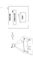
- FIG. 1 is a diagram showing an example of the overall configuration of the weight estimation system 1 according to the present embodiment.
- the body weight estimation system 1 includes a body weight estimation device 10 for estimating body weight and a camera device 20 for photographing a pig P, which is a body weight estimation target.
- the weight estimation device 10 and the camera device 20 are communicably connected to each other by, for example, wirelessly, wiredly, or both.
- the camera device 20 is a digital camera, a smartphone, a tablet terminal, or the like used by a photographer who shoots a pig P. The photographer can obtain imaging data by photographing the pig P from above the pig P using the camera device 20.
- the camera device 20 may be a camera fixedly installed at a predetermined position.
- the camera device 20 is provided with a depth sensor, measures the depth of each point within the shooting range, and generates shooting data indicating the height of each of these points. Therefore, the shooting data generated by the camera device 20 is represented by a point cloud of (x, y, z), where each position in the shooting range is (x, y) and the depth value at each of these positions is z. NS.
- the shooting data represented by the point cloud (x, y, z) will be referred to as “point cloud data”.
- the body weight estimation device 10 is a computer or computer system that estimates the body weight of the pig P from the point cloud data generated by the camera device 20.
- the body weight estimation device 10 estimates the body weight of the pig P by a regression equation calculated using the learning data prepared in advance.
- the training data is data for calculating a regression equation. For example, it is represented by a set of a point cloud data generated by photographing a pig P whose body weight is known and a correct weight indicating the weight of the pig P. Will be done.
- the regression equation may be called a regression model or the like, and is an example of an estimation model for estimating the weight of the estimation target.
- the weight estimation device 10 includes a weight estimation processing unit 100 and a storage unit 110.
- the weight estimation processing unit 100 is realized by processing one or more programs installed in the weight estimation device 10 to be executed by a processor such as a CPU (Central Processing Unit).
- the storage unit 110 can be realized by using an auxiliary storage device such as an HDD (Hard Disk Drive) or an SSD (Solid State Drive), for example.
- the body weight estimation device 10 uses the weight estimation processing unit 100 to calculate a regression equation for estimating the weight of the pig P using the training data prepared in advance, and the weight of the pig P is calculated by this regression equation. Execute the "weight estimation process" to estimate. Further, the storage unit 110 contains information necessary for executing the learning process and the body weight estimation process and various processing results (for example, learning data, a regression equation, point group data of the pig P to be weight-estimated, a body weight estimation result, and the like. ) Is memorized.
- the overall configuration of the weight estimation system 1 shown in FIG. 1 is an example, and may be another configuration.
- the weight estimation system 1 may include a plurality of camera devices 20.
- a part or all of the weight estimation processing unit 100 may be realized by a function provided by a cloud service or the like.
- the shooting conditions when the photographer shoots the pig P using the camera device 20 will be described.
- the photographing screen 1000 shown in FIG. 2 is displayed on the display or the like of the camera device 20.
- a guide 1100 for adjusting the shooting position of the pig P is displayed on the shooting screen 1000.
- the guide 1100 includes a guide 1110 indicating the center of the photographing range.
- the shooting direction is the positive direction of the z-axis
- the downward direction of the shooting screen 1000 (that is, the head direction of the pig P) is the positive direction of the x-axis
- the right direction of the shooting screen 1000 (that is, the left side direction of the pig P). Is the positive direction of the y-axis.
- the photographer moves the camera device 20 above the pig P, adjusts the contour of the pig P to match the frame indicated by the guide 1100, and then presses the shooting button 1200 to shoot the pig P. ..
- the shooting button 1200 to shoot the pig P. ..
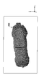
- the point cloud data 2000 generated by photographing a certain pig P with the camera device 20 will be described.
- the point cloud data 2000 is a set of points (x, y, z) in the xyz space.
- the head direction of the pig P is the positive direction of the x-axis
- the left side direction of the pig P is the positive direction of the y-axis
- the shooting direction of the camera device 20 is. It is the positive direction of the z-axis.
- FIG. 4 is a diagram showing an example of the functional configuration of the body weight estimation processing unit 100 according to the present embodiment.
- the acquisition unit 101 acquires (reads) the learning data stored in the storage unit 110 in the learning process.
- the learning data is data represented by a set of a point cloud data generated by photographing a pig P whose body weight is known and a correct answer weight indicating the weight of the pig P. be.
- the acquisition unit 101 acquires the point cloud data generated by photographing the pig P to be weight-estimated from the storage unit 110 (or the camera device 20) in the weight estimation process.
- the pre-processing unit 102 performs a predetermined pre-processing on the point cloud data acquired by the acquisition unit 101 in the learning process and the weight estimation process.
- preprocessing for example, when points other than the tonp P portion are included in the point cloud data, such points are removed, or the point cloud of the tonp P portion is resampled and converted to a predetermined resolution. Resampling and processing can be mentioned.
- the pretreatment is a treatment for improving the accuracy of estimating the body weight of the pig, and does not necessarily have to be performed.
- the image creation unit 103 creates a projected image in which the point cloud data after the preprocessing is projected onto the xy plane in the learning process and the weight estimation process.
- the processing unit 104 performs processing for removing the head portion and the tail portion of the pig P from the point cloud data and the projected image after the preprocessing. This is because the head and tail parts of the pig move during shooting, and the head and tail parts are included or not included in the point cloud data, which adversely affects the weight estimation accuracy.
- the index value calculation unit 105 calculates a predetermined index value by using the point cloud data after processing and the projected image after processing in the learning process and the weight estimation process.
- the following four index values are calculated.
- the regression equation calculation unit 106 calculates the regression equation using the index value calculated by the index value calculation unit 105 and the correct body weight in the learning process.
- the regression equation is represented by the following equation (1).
- Estimated weight a 1 x (corrected projected area) + a 2 x (posture correction value) + a 3 x (shooting height correction value) + a 4 x (body length) / (body width) + b ...
- a 1 , a 2 , a 3 , a 4 , and b are parameters of the regression equation.
- the regression equation calculation unit 106 calculates the regression equation by estimating these parameters a 1 , a 2 , a 3 , a 4 , and b by a known method (for example, the least squares method).
- the parameter corresponding to the unused index value (that is, the parameter to be multiplied by the index value) is selected. It may be set to 0.
- the body weight estimation unit 107 estimates the weight of the pig P by the regression equation shown in the above equation (1) using the index value calculated by the index value calculation unit 105.
- the parameters a 1 , a 2 , a 3 , a 4 , and b estimated in the learning process are used.
- the preprocessing unit 102 performs a predetermined preprocessing on the point cloud data included in the learning data acquired in step S101 above (step S102).
- preprocessing for the point cloud data it is assumed that points other than the tonp P portion are removed and conversion to a predetermined resolution is performed by resampling the point cloud of the tonp P portion.
- the conversion to a predetermined resolution by resampling means that each point included in the point cloud data is resampled and a three-dimensional point cloud group having a predetermined predetermined interval (for example, the interval between adjacent points) is set. It means to obtain a point cloud (such as a point cloud that is 1.0 cm).
- the image creation unit 103 uses the point cloud data preprocessed in step S102 above (or, if no preprocessing is performed, the point cloud data included in the training data acquired in step S101 above). ) Is projected onto the xy plane to create a projected image (step S103).
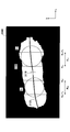
- a projected image is shown in FIG.
- the projected image 3000 shown in FIG. 6 is an image obtained by projecting the point cloud data 2000 onto a certain xy plane, and includes the pig region 3100 on which the point cloud of the pig P portion of the point cloud data 2000 is projected.
- the point 3110 is the origin of the xy plane, and the point at the position indicated by the guide 1110 in FIG. 2 is projected onto the xy plane.
- the image creation unit 103 may calculate a dividing line 3120 that divides the pig region 3100 in the projected image 3000 into left and right (left and right with respect to the traveling direction when the pig walks).
- a dividing line 3120 is when the x-coordinate value included in the pig region 3100 is x 1 , x 2 , ..., X M, and the x-coordinate value is x i (1 ⁇ i ⁇ M).
- the processing unit 104 uses the point cloud data preprocessed in step S102 above (or, if no preprocessing is performed, the point cloud data included in the learning data acquired in step S101 above). And the projected image created in step S103 above, processing is performed to remove the head portion and the tail portion of the pig P (step S104).
- the processing unit 104 performs the processing according to the following Steps 1 to 7. In the following, as an example, a case where the point cloud data 2000 shown in FIG. 3 and the projected image 3000 shown in FIG. 6 are processed will be described.
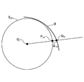
- Step2 Next, the processing unit 104 creates a circle S 11 that is a point on the boundary of the pig region 3100 and fits the point included in the search region R 11 (that is, a circle that approximates these point groups). presume. Similarly, the processing section 104 estimates a circle S 11 that is a point on the boundary of the pig region 3100 and fits the point included in the search region R 21. Hereinafter, these circles will be referred to as "fit circle candidates".
- the fit circle candidate can be estimated by the least squares method. For example, refer to "https://myenigma.hatenablog.com/entry/2015/1507/214600".
- R 1j ⁇ (x, y)
- x 1j ⁇ x ⁇ x 1j + L ⁇ and R 2j ⁇ (x, y)
- d 1 , d 2 > 0 are preset values.
- the processing unit 104 slides the search area R 1 (j-1) by d 1 in the x-axis direction to make the search area R 1j, and sets the search area R 2 (j-1) in the x-axis direction. Slide d 2 to obtain the search area R 2j .
- Step4 Next, the processing unit 104 estimates a circle S1j that is a point on the boundary of the pig region 3100 and fits the point included in the search region R1j. Similarly, the processing unit 104 estimates a circle S 11 that is a point on the boundary of the pig region 3100 and fits the point included in the search region R 2j.
- Steps 3 to 4 described above are repeated, for example, with the range of values that the x coordinate can take in the projected image 3000 as X 1 ⁇ x ⁇ X 2 until x 21 ⁇ L ⁇ X 1 and X 2 ⁇ x 1j + L are satisfied. Will be executed. As a result, a set of fit circle candidates ⁇ S 1j ⁇ and ⁇ S 2j ⁇ can be obtained.
- Step5 Then, the processing unit 104 from the set of fit circle candidate ⁇ S 1j ⁇ with selecting fit circle S 1 for removing head portion, from the set of fit circle candidate ⁇ S 2j ⁇ to select the fit circle S 2 to remove the tail portion.
- the processing unit 104 from the set of fit circle candidate ⁇ S 1j ⁇ with selecting fit circle S 1 for removing head portion, from the set of fit circle candidate ⁇ S 2j ⁇ to select the fit circle S 2 to remove the tail portion.
- a method of selecting the fit circle S 1 will be described.
- x-coordinate is the largest-fit circle candidate at medium (that is, an error takes a minimum value, and fit circle candidate on the most right side) may be selected as fit circle S 1.
- fit circle S 2 when selecting the fitting circle S 2 from the degree of change of the error is smallest x-coordinate among the fit circle candidate error takes a minimum value fit circle candidate (i.e., an error takes a minimum value, and fit circle candidate on the leftmost) is selected as the fit circle S 2.
- Step 6 Then, the processing unit 104 removes the head portion and the tail portion in the pig region 3100 by using the fit circles S 1 and S 2 obtained in the above Step 5, respectively.
- the machined portion 104 selects the straight line parallel to the y-axis and in contact with the fit circle S 1 with the larger x-coordinate value as T 1. as deletes the region x-coordinate value is greater than the straight line T 1 in pigs region 3100. As a result, the head portion in the pig region 3100 is removed.
- the processing unit 104 is parallel to the y-axis, and, among the line tangent to fit circle S 2, a straight line towards the x-coordinate value is smaller As T 2 , the region of the pig region 3100 whose x-coordinate value is smaller than that of the straight line T 2 is deleted. As a result, the tail portion in the pig region 3100 is removed.
- a large x-coordinate value of the center of the fit circle S 1, and each on the circumference of the fit circle S 1 of The area in which the x-coordinate value is larger than the point may be deleted.
- the x-coordinate value is smaller than the center of the fitting circle S 2
- an area in the range x-coordinate value is smaller than the points on the circumference of the fitting circle S 2 You may.
- both the head portion and the tail portion in the pig region 3100 were removed, but for example, instead of removing both, only one of them may be removed. Further, when the area of the area to be removed (deleted) is equal to or less than a predetermined threshold value, the area may not be removed.
- Step 7 Finally, the processed portion 104 is projected onto the head portion and the tail portion when creating the point cloud (that is, the projected image 3000) corresponding to the portions (head portion and tail portion) removed in Step 6 above.
- the point cloud is removed from the point cloud data 2000.
- the index value calculation unit 105 calculates the corrected projected area, the posture correction value, the shooting height correction value, and the body length and body width as index values (step S105). The calculation method of each index value will be described below.
- 1.0 / sin ⁇ ⁇ 1.12 corrects the x-axis direction of the side of the unit region V 1 ⁇ V 5 by (i.e., multiplied by 1.0 / sin [theta), corrected
- the rear unit area is W 1 to W 5 .
- the area of the corrected unit area W 1 ⁇ W 5 calculates the area of the pig region 3100. This area is the corrected projection area.
- the side in the x-axis direction of the unit region is corrected, but the side in the y-axis direction may be corrected, and both the side in the x-axis direction and the side in the y-axis direction are corrected. May be done.
- the posture correction value is calculated as an index value.
- f be a polynomial function that approximates the points (x, y, z) corresponding to the points (x, y) on the dividing line 3120 described in FIG. That is, let f be a polynomial function such that z ⁇ f (x, y), (where (x, y) is a point on the dividing line 3120).
- a function f can be obtained by, for example, a library such as polyfit.
- a predetermined coefficient of the polynomial function f (for example, a quadratic coefficient of x, a quadratic coefficient of y, a coefficient of xy, etc.) is used as the posture correction value.
- a predetermined coefficient of the polynomial function f for example, a quadratic coefficient of x
- the posture correction value for example, a quadratic coefficient of x
- the distance from the camera device 20 to the pig P varies depending on the height of the photographer, the length of the hand, and the like, which may affect the accuracy of weight estimation. Therefore, the shooting height correction value is calculated as an index value.
- the body length and width are calculated as index values.
- a straight line 3130 that passes through the point 3110 (that is, the origin of the xy plane) and ends at a point on the boundary of the pig region 3100 is calculated and is orthogonal to the dividing line 3120. Then, the length of this straight line 3130 may be the body width.
- the points (x, y, z) corresponding to the points (x, y) on the dividing line 3120 are defined.
- the function to be approximated may be f, and the length of the curve 2110 represented by this function f may be the body length.
- the regression equation calculation unit 106 calculates the regression equation using the index value and the correct body weight corresponding to each learning data (step S106). That is, the regression equation calculation unit 106 initializes the parameters a 1 , a 2 , a 3 , a 4 , and b to appropriate initial values, and then uses the index value corresponding to the training data for each training data. The estimated body weight is calculated by the above formula (1). Then, the regression equation calculation unit 106 calculates the difference between the estimated body weight and the correct body weight corresponding to the learning data, and then minimizes the sum of the squares of the differences calculated for each learning data. , Parameters a 1 , a 2 , a 3 , a 4 , b are estimated. As a result, a regression equation for estimating the body weight of pig P is calculated.
- FIG. 13 is a flowchart showing an example of the weight estimation process according to the present embodiment.
- the parameters a 1 , a 2 , a 3 , a 4 , and b of the regression equation shown in the above equation (1) those estimated by the above learning process are used.
- the acquisition unit 101 acquires the point cloud data generated by photographing the pig P whose body weight is to be estimated from the storage unit 110 (or the camera device 20) (step S201).
- the preprocessing unit 102 performs a predetermined preprocessing on the point cloud data acquired in the above step S201 in the same manner as in step S102 of FIG. 5 (step S202).
- the image creation unit 103 is acquired in the point cloud data (or, if the preprocessing is not performed, in the above step S201) that was preprocessed in the above step S202, similarly to the step S103 in FIG.
- a projected image is created by projecting the point cloud data) onto the xy plane (step S203).
- the processing unit 104 was acquired in the point cloud data (or, if the preprocessing is not performed, in the above step S201) that was preprocessed in the above step S202, similarly to the step S104 in FIG.
- the point cloud data) and the projected image created in step S203 are processed to remove the head portion and the tail portion of the pig P (step S204).
- the index value calculation unit 105 calculates the corrected projected area, the posture correction value, the shooting height correction value, and the body length and body width as index values (step S205).
- the body weight estimation unit 107 estimates the weight of the pig P by the regression equation shown in the above equation (1) using the index value calculated in the above step S205 (step S206). From this, the weight of the pig P is estimated.
- Weight estimation system 10 Weight estimation device 20 Camera device 100 Weight estimation processing unit 101 Acquisition unit 102 Preprocessing unit 103 Image creation unit 104 Processing unit 105 Index value calculation unit 106 Regression formula calculation unit 107 Weight estimation unit 110 Storage unit
Landscapes
- Physics & Mathematics (AREA)
- General Physics & Mathematics (AREA)
- Length Measuring Devices By Optical Means (AREA)
Abstract
This weight estimation device according to one embodiment is characterized by comprising: an acquisition means which acquires three-dimensional point group data representing a depth value at each point of a weight estimation target; a creation means which creates a projection image in which the point group data acquired by the acquisition means is projected onto a two-dimensional plane; a calculation means which calculates a prescribed index value by using at least one among the point group data and the projection image; and an estimation means which uses the index value calculated by the calculation means to estimate the weight of the estimation target by using a pre-created estimation model.
Description
本発明は、体重推定装置、体重推定方法及びプログラムに関する。
The present invention relates to a weight estimation device, a weight estimation method and a program.
畜産農家では、飼育している家畜の体重を把握することが従来から行われている。これは、例えば、豚等の家畜では、或る体重を超えると食肉としての価値が下がってしまうことがあるためである。
Livestock farmers have traditionally been able to keep track of the weight of the livestock they are raising. This is because, for example, in domestic animals such as pigs, the value as meat may decrease when the body weight exceeds a certain level.
ところで、畜産農家で飼育されている家畜は数百頭(又は数百匹、数百羽等)を超える場合がある。このため、体重計等を用いる場合、家畜の体重の把握には手間を要する。これに対して、家畜をビデオカメラで撮影し、撮影した画像中における家畜の面積から体重を推定する技術が知られている(例えば、特許文献1参照)。
By the way, the number of livestock raised by livestock farmers may exceed hundreds (or hundreds, hundreds, etc.). Therefore, when using a weight scale or the like, it takes time and effort to grasp the weight of livestock. On the other hand, there is known a technique of photographing livestock with a video camera and estimating the weight from the area of the livestock in the captured image (see, for example, Patent Document 1).
しかしながら、様々な原因(例えば、撮影時における家畜の姿勢、カメラと家畜との距離等)により、上記の従来技術では、推定された体重と真の体重との誤差が大きかった。
However, due to various causes (for example, the posture of the livestock at the time of shooting, the distance between the camera and the livestock, etc.), the error between the estimated body weight and the true body weight was large in the above-mentioned conventional technique.
本発明の一実施形態は、上記の点に鑑みてなされたもので、高い精度で体重を推定することを目的とする。
One embodiment of the present invention has been made in view of the above points, and an object of the present invention is to estimate the body weight with high accuracy.
上記目的を達成するため、一実施形態に係る体重推定装置は、体重の推定対象の各点における深度値を表す三次元の点群データを取得する取得手段と、前記取得手段により取得された前記点群データを2次元平面上に投影した投影画像を作成する作成手段と、前記点群データと前記投影画像との少なくとも一方を用いて、所定の指標値を算出する算出手段と、前記算出手段により算出された前記指標値を用いて、予め作成された推定モデルにより前記推定対象の体重を推定する推定手段と、を有することを特徴とする。
In order to achieve the above object, the weight estimation device according to the embodiment includes an acquisition means for acquiring three-dimensional point cloud data representing a depth value at each point of the weight estimation target, and the acquisition means acquired by the acquisition means. A creating means for creating a projected image in which point cloud data is projected on a two-dimensional plane, a calculating means for calculating a predetermined index value using at least one of the point cloud data and the projected image, and the calculating means. It is characterized by having an estimation means for estimating the weight of the estimation target by a estimation model created in advance using the index value calculated by.
高い精度で体重を推定することができる。
The weight can be estimated with high accuracy.
以下、本発明の一実施形態について、図面を参照しながら説明する。本実施形態では、高い精度で豚の体重を推定することが可能な体重推定システム1について説明する。なお、本実施形態では、体重の推定対象となる家畜の一例として豚を想定して説明するが、家畜は豚に限られず、例えば、牛、馬、羊、鶏等の種々の家畜であってもよい。また、体重の推定対象は家畜だけでなく、例えば、愛玩動物(いわゆるペット)や野生動物等であってもよい。
Hereinafter, an embodiment of the present invention will be described with reference to the drawings. In this embodiment, a weight estimation system 1 capable of estimating the weight of a pig with high accuracy will be described. In the present embodiment, a pig is assumed as an example of livestock for which the weight is estimated, but the livestock is not limited to pigs, and is, for example, various livestock such as cows, horses, sheep, and chickens. May be good. Further, the body weight estimation target is not limited to livestock, but may be, for example, pet animals (so-called pets), wild animals, and the like.
<全体構成>
まず、本実施形態に係る体重推定システム1の全体構成について、図1を参照しながら説明する。図1は、本実施形態に係る体重推定システム1の全体構成の一例を示す図である。 <Overall configuration>
First, the overall configuration of theweight estimation system 1 according to the present embodiment will be described with reference to FIG. FIG. 1 is a diagram showing an example of the overall configuration of the weight estimation system 1 according to the present embodiment.
まず、本実施形態に係る体重推定システム1の全体構成について、図1を参照しながら説明する。図1は、本実施形態に係る体重推定システム1の全体構成の一例を示す図である。 <Overall configuration>
First, the overall configuration of the
図1に示すように、本実施形態に係る体重推定システム1には、体重の推定を行う体重推定装置10と、体重の推定対象である豚Pを撮影するカメラ装置20とが含まれる。体重推定装置10とカメラ装置20とは、例えば、無線若しくは有線又はその両方により通信可能に接続されている。
As shown in FIG. 1, the body weight estimation system 1 according to the present embodiment includes a body weight estimation device 10 for estimating body weight and a camera device 20 for photographing a pig P, which is a body weight estimation target. The weight estimation device 10 and the camera device 20 are communicably connected to each other by, for example, wirelessly, wiredly, or both.
カメラ装置20は、豚Pを撮影する撮影者が利用するデジタルカメラ、スマートフォン、タブレット端末等である。撮影者は、カメラ装置20を用いて、豚Pの上方から当該豚Pを撮影することで撮影データを得ることができる。なお、カメラ装置20は所定の位置に固定的に設置されたカメラであってもよい。
The camera device 20 is a digital camera, a smartphone, a tablet terminal, or the like used by a photographer who shoots a pig P. The photographer can obtain imaging data by photographing the pig P from above the pig P using the camera device 20. The camera device 20 may be a camera fixedly installed at a predetermined position.
ここで、カメラ装置20には深度センサが備えられており、撮影範囲内における各点の深度を測定し、これら各点の高さを表す撮影データを生成するものとする。したがって、カメラ装置20により生成される撮影データは、撮影範囲内の各位置を(x,y)、これらの各位置における深度値をzとして、(x,y,z)の点群で表される。以降では、(x,y,z)の点群で表される撮影データを「点群データ」と表す。
Here, the camera device 20 is provided with a depth sensor, measures the depth of each point within the shooting range, and generates shooting data indicating the height of each of these points. Therefore, the shooting data generated by the camera device 20 is represented by a point cloud of (x, y, z), where each position in the shooting range is (x, y) and the depth value at each of these positions is z. NS. Hereinafter, the shooting data represented by the point cloud (x, y, z) will be referred to as “point cloud data”.
体重推定装置10は、カメラ装置20が生成した点群データから豚Pの体重を推定するコンピュータ又はコンピュータシステムである。体重推定装置10は、予め準備した学習データを用いて算出した回帰式により、豚Pの体重を推定する。学習データは回帰式を算出するためのデータであり、例えば、体重が既知である豚Pを撮影することで生成された点群データと、この豚Pの体重を示す正解体重との組で表される。なお、回帰式は回帰モデル等と称されてもよく、推定対象の体重を推定するための推定モデルの一例である。
The body weight estimation device 10 is a computer or computer system that estimates the body weight of the pig P from the point cloud data generated by the camera device 20. The body weight estimation device 10 estimates the body weight of the pig P by a regression equation calculated using the learning data prepared in advance. The training data is data for calculating a regression equation. For example, it is represented by a set of a point cloud data generated by photographing a pig P whose body weight is known and a correct weight indicating the weight of the pig P. Will be done. The regression equation may be called a regression model or the like, and is an example of an estimation model for estimating the weight of the estimation target.
ここで、体重推定装置10には、体重推定処理部100と、記憶部110とが含まれる。体重推定処理部100は、体重推定装置10にインストールされた1以上のプログラムが、CPU(Central Processing Unit)等のプロセッサに実行させる処理により実現される。また、記憶部110は、例えば、HDD(Hard Disk Drive)やSSD(Solid State Drive)等の補助記憶装置を用いて実現可能である。
Here, the weight estimation device 10 includes a weight estimation processing unit 100 and a storage unit 110. The weight estimation processing unit 100 is realized by processing one or more programs installed in the weight estimation device 10 to be executed by a processor such as a CPU (Central Processing Unit). Further, the storage unit 110 can be realized by using an auxiliary storage device such as an HDD (Hard Disk Drive) or an SSD (Solid State Drive), for example.
体重推定装置10は、体重推定処理部100により、予め準備した学習データを用いて豚Pの体重を推定するための回帰式を算出する「学習処理」と、この回帰式により豚Pの体重を推定する「体重推定処理」とを実行する。また、記憶部110には、学習処理及び体重推定処理の実行に必要な情報や各種処理結果(例えば、学習データや回帰式、体重の推定対象の豚Pの点群データ、体重の推定結果等)が記憶される。
The body weight estimation device 10 uses the weight estimation processing unit 100 to calculate a regression equation for estimating the weight of the pig P using the training data prepared in advance, and the weight of the pig P is calculated by this regression equation. Execute the "weight estimation process" to estimate. Further, the storage unit 110 contains information necessary for executing the learning process and the body weight estimation process and various processing results (for example, learning data, a regression equation, point group data of the pig P to be weight-estimated, a body weight estimation result, and the like. ) Is memorized.
なお、図1に示す体重推定システム1の全体構成は一例であって、他の構成であってもよい。例えば、体重推定システム1には複数のカメラ装置20が含まれていてもよい。また、体重推定処理部100の一部又は全部が、クラウドサービス等により提供される機能で実現されていてもよい。
The overall configuration of the weight estimation system 1 shown in FIG. 1 is an example, and may be another configuration. For example, the weight estimation system 1 may include a plurality of camera devices 20. Further, a part or all of the weight estimation processing unit 100 may be realized by a function provided by a cloud service or the like.
<撮影条件>
ここで、カメラ装置20を用いて撮影者が豚Pを撮影する際の撮影条件について説明する。豚Pを撮影する際、カメラ装置20のディスプレイ等には、例えば、図2に示す撮影画面1000が表示される。撮影画面1000には豚Pの撮影位置を合わせるためのガイド1100が表示されている。また、ガイド1100には、撮影範囲の中心を示すガイド1110が含まれている。ここで、本実施形態では、点群データの原点(つまり、(x,y,z)=(0,0,0)となる位置)はカメラ装置20のカメラ位置であるものとする。したがって、ガイド1110が示す位置は点群データの任意のxy平面における原点(つまり、(x,y)=(0,0))である。なお、撮影方向をz軸の正の方向、撮影画面1000の下方向(つまり、豚Pの頭方向)をx軸の正の方向、撮影画面1000の右方向(つまり、豚Pの左側方向)をy軸の正の方向とする。 <Shooting conditions>
Here, the shooting conditions when the photographer shoots the pig P using thecamera device 20 will be described. When photographing the pig P, for example, the photographing screen 1000 shown in FIG. 2 is displayed on the display or the like of the camera device 20. A guide 1100 for adjusting the shooting position of the pig P is displayed on the shooting screen 1000. Further, the guide 1100 includes a guide 1110 indicating the center of the photographing range. Here, in the present embodiment, it is assumed that the origin of the point cloud data (that is, the position where (x, y, z) = (0,0,0) is) is the camera position of the camera device 20. Therefore, the position indicated by the guide 1110 is the origin (that is, (x, y) = (0,0)) in any xy plane of the point cloud data. The shooting direction is the positive direction of the z-axis, the downward direction of the shooting screen 1000 (that is, the head direction of the pig P) is the positive direction of the x-axis, and the right direction of the shooting screen 1000 (that is, the left side direction of the pig P). Is the positive direction of the y-axis.
ここで、カメラ装置20を用いて撮影者が豚Pを撮影する際の撮影条件について説明する。豚Pを撮影する際、カメラ装置20のディスプレイ等には、例えば、図2に示す撮影画面1000が表示される。撮影画面1000には豚Pの撮影位置を合わせるためのガイド1100が表示されている。また、ガイド1100には、撮影範囲の中心を示すガイド1110が含まれている。ここで、本実施形態では、点群データの原点(つまり、(x,y,z)=(0,0,0)となる位置)はカメラ装置20のカメラ位置であるものとする。したがって、ガイド1110が示す位置は点群データの任意のxy平面における原点(つまり、(x,y)=(0,0))である。なお、撮影方向をz軸の正の方向、撮影画面1000の下方向(つまり、豚Pの頭方向)をx軸の正の方向、撮影画面1000の右方向(つまり、豚Pの左側方向)をy軸の正の方向とする。 <Shooting conditions>
Here, the shooting conditions when the photographer shoots the pig P using the
撮影者は豚Pの上方にカメラ装置20を移動させて、ガイド1100が示す枠に豚Pの輪郭が合致するように調整した上で、撮影ボタン1200を押下することで当該豚Pを撮影する。これにより、複数の豚Pをそれぞれ撮影した場合であっても、xyz空間における原点と豚Pを表す点群との相対的な位置関係がほぼ同様の点群データを得ることが可能となる。
The photographer moves the camera device 20 above the pig P, adjusts the contour of the pig P to match the frame indicated by the guide 1100, and then presses the shooting button 1200 to shoot the pig P. .. As a result, even when a plurality of pigs P are photographed, it is possible to obtain point cloud data in which the relative positional relationship between the origin and the point cloud representing the pig P in the xyz space is substantially the same.
<点群データ>
次に、或る豚Pをカメラ装置20で撮影することで生成された点群データ2000について説明する。図3に示すように、点群データ2000は、xyz空間内の点(x,y,z)の集合である。なお、上述したように、カメラ装置20のカメラ位置を原点として、豚Pの頭方向がx軸の正の方向、豚Pの左側方向がy軸の正の方向、カメラ装置20の撮影方向がz軸の正の方向である。 <Point cloud data>
Next, thepoint cloud data 2000 generated by photographing a certain pig P with the camera device 20 will be described. As shown in FIG. 3, the point cloud data 2000 is a set of points (x, y, z) in the xyz space. As described above, with the camera position of the camera device 20 as the origin, the head direction of the pig P is the positive direction of the x-axis, the left side direction of the pig P is the positive direction of the y-axis, and the shooting direction of the camera device 20 is. It is the positive direction of the z-axis.
次に、或る豚Pをカメラ装置20で撮影することで生成された点群データ2000について説明する。図3に示すように、点群データ2000は、xyz空間内の点(x,y,z)の集合である。なお、上述したように、カメラ装置20のカメラ位置を原点として、豚Pの頭方向がx軸の正の方向、豚Pの左側方向がy軸の正の方向、カメラ装置20の撮影方向がz軸の正の方向である。 <Point cloud data>
Next, the
なお、1つの点群データがどの程度の数の点の集合で構成されるかは、例えば、カメラ装置20の解像度等によって異なる。
Note that how many points a set of points is composed of one point cloud data depends on, for example, the resolution of the camera device 20 and the like.
<機能構成>
次に、本実施形態に係る体重推定処理部100の機能構成について、図4を参照しながら説明する。図4は、本実施形態に係る体重推定処理部100の機能構成の一例を示す図である。 <Functional configuration>
Next, the functional configuration of the body weightestimation processing unit 100 according to the present embodiment will be described with reference to FIG. FIG. 4 is a diagram showing an example of the functional configuration of the body weight estimation processing unit 100 according to the present embodiment.
次に、本実施形態に係る体重推定処理部100の機能構成について、図4を参照しながら説明する。図4は、本実施形態に係る体重推定処理部100の機能構成の一例を示す図である。 <Functional configuration>
Next, the functional configuration of the body weight
図4に示すように、本実施形態に係る体重推定処理部100には、取得部101と、前処理部102と、画像作成部103と、加工部104と、指標値算出部105と、回帰式算出部106と、体重推定部107とが含まれる。
As shown in FIG. 4, the weight estimation processing unit 100 according to the present embodiment includes the acquisition unit 101, the preprocessing unit 102, the image creation unit 103, the processing unit 104, the index value calculation unit 105, and regression. The formula calculation unit 106 and the weight estimation unit 107 are included.
取得部101は、学習処理において、記憶部110に記憶されている学習データを取得する(読み込み)。上述したように、学習データとは、体重が既知である豚Pを撮影することで生成された点群データと、この豚Pの体重を示す正解体重との組で表されるデータのことである。
The acquisition unit 101 acquires (reads) the learning data stored in the storage unit 110 in the learning process. As described above, the learning data is data represented by a set of a point cloud data generated by photographing a pig P whose body weight is known and a correct answer weight indicating the weight of the pig P. be.
また、取得部101は、体重推定処理において、体重の推定対象の豚Pを撮影することで生成された点群データを記憶部110(又はカメラ装置20)から取得する。
Further, the acquisition unit 101 acquires the point cloud data generated by photographing the pig P to be weight-estimated from the storage unit 110 (or the camera device 20) in the weight estimation process.
前処理部102は、学習処理及び体重推定処理において、取得部101により取得された点群データに対して所定の前処理を行う。ここで、前処理としては、例えば、豚P部分以外の点が点群データに含まれる場合にこのような点を除去したり、豚P部分の点群をリサンプリングして所定の解像度に変換したり処理等が挙げられる。なお、前処理は豚の体重の推定精度を向上させるための処理であり、必ずしも行われなくてもよい。
The pre-processing unit 102 performs a predetermined pre-processing on the point cloud data acquired by the acquisition unit 101 in the learning process and the weight estimation process. Here, as preprocessing, for example, when points other than the tonp P portion are included in the point cloud data, such points are removed, or the point cloud of the tonp P portion is resampled and converted to a predetermined resolution. Resampling and processing can be mentioned. The pretreatment is a treatment for improving the accuracy of estimating the body weight of the pig, and does not necessarily have to be performed.
画像作成部103は、学習処理及び体重推定処理において、前処理後の点群データをxy平面に投影した投影画像を作成する。
The image creation unit 103 creates a projected image in which the point cloud data after the preprocessing is projected onto the xy plane in the learning process and the weight estimation process.
加工部104は、学習処理及び体重推定処理において、前処理後の点群データ及び投影画像に対して、豚Pの頭部分や尻尾部分を除去する加工を行う。これは、豚の頭部分や尻尾部分が撮影時に動くことで、頭部分や尻尾部分が点群データに含まれたり含まれなかったりするため、体重の推定精度に悪影響を与えるためである。
In the learning process and the weight estimation process, the processing unit 104 performs processing for removing the head portion and the tail portion of the pig P from the point cloud data and the projected image after the preprocessing. This is because the head and tail parts of the pig move during shooting, and the head and tail parts are included or not included in the point cloud data, which adversely affects the weight estimation accuracy.
指標値算出部105は、学習処理及び体重推定処理において、加工後の点群データと加工後の投影画像とを用いて、所定の指標値を算出する。ここで、本実施形態では、以下の4つの指標値を算出するものとする。
The index value calculation unit 105 calculates a predetermined index value by using the point cloud data after processing and the projected image after processing in the learning process and the weight estimation process. Here, in the present embodiment, the following four index values are calculated.
・補正投影面積
・姿勢補正値
・撮影高さ補正値
・体長及び体幅
ここで、補正投影面積とは、豚Pの体表面の傾き(傾斜)を考慮して、投影画像の面積を補正した値のことである。姿勢補正値は、豚Pの姿勢(例えば、首を上げている又は下げている等)を表す値のことである。撮影高さ補正値は、カメラ装置20から豚Pまでの距離を表す値のことである。体長及び体幅は、豚Pの体長及び体幅をそれぞれ表す値である。 -Corrected projected area-Posture correction value-Shooting height correction value-Body length and body width Here, the corrected projected area is the area of the projected image corrected in consideration of the inclination (inclination) of the body surface of the pig P. It is a value. The posture correction value is a value representing the posture of the pig P (for example, raising or lowering the neck). The shooting height correction value is a value representing the distance from thecamera device 20 to the pig P. The body length and the body width are values representing the body length and the body width of the pig P, respectively.
・姿勢補正値
・撮影高さ補正値
・体長及び体幅
ここで、補正投影面積とは、豚Pの体表面の傾き(傾斜)を考慮して、投影画像の面積を補正した値のことである。姿勢補正値は、豚Pの姿勢(例えば、首を上げている又は下げている等)を表す値のことである。撮影高さ補正値は、カメラ装置20から豚Pまでの距離を表す値のことである。体長及び体幅は、豚Pの体長及び体幅をそれぞれ表す値である。 -Corrected projected area-Posture correction value-Shooting height correction value-Body length and body width Here, the corrected projected area is the area of the projected image corrected in consideration of the inclination (inclination) of the body surface of the pig P. It is a value. The posture correction value is a value representing the posture of the pig P (for example, raising or lowering the neck). The shooting height correction value is a value representing the distance from the
回帰式算出部106は、学習処理において、指標値算出部105により算出された指標値と、正解体重とを用いて、回帰式を算出する。ここで、本実施形態では、回帰式は以下式(1)で表されるものとする。
The regression equation calculation unit 106 calculates the regression equation using the index value calculated by the index value calculation unit 105 and the correct body weight in the learning process. Here, in the present embodiment, the regression equation is represented by the following equation (1).
推定体重=a1×(補正投影面積)+a2×(姿勢補正値)+a3×(撮影高さ補正値)+a4×(体長)/(体幅)+b ・・・(1)
ここで、a1,a2,a3,a4,bは回帰式のパラメータである。回帰式算出部106は、これらのパラメータa1,a2,a3,a4,bを既知の手法(例えば、最小二乗法等)により推定することで、回帰式を算出する。 Estimated weight = a 1 x (corrected projected area) + a 2 x (posture correction value) + a 3 x (shooting height correction value) + a 4 x (body length) / (body width) + b ... (1)
Here, a 1 , a 2 , a 3 , a 4 , and b are parameters of the regression equation. The regressionequation calculation unit 106 calculates the regression equation by estimating these parameters a 1 , a 2 , a 3 , a 4 , and b by a known method (for example, the least squares method).
ここで、a1,a2,a3,a4,bは回帰式のパラメータである。回帰式算出部106は、これらのパラメータa1,a2,a3,a4,bを既知の手法(例えば、最小二乗法等)により推定することで、回帰式を算出する。 Estimated weight = a 1 x (corrected projected area) + a 2 x (posture correction value) + a 3 x (shooting height correction value) + a 4 x (body length) / (body width) + b ... (1)
Here, a 1 , a 2 , a 3 , a 4 , and b are parameters of the regression equation. The regression
なお、本実施形態では、上記の4つの指標値を用いる場合について説明するが、これら4つの指標値を全て用いる必要はなく、少なくとも1つの指標値が用いられればよい。このような場合、上記の式(1)のパラメータa1,a2,a3,a4のうち、用いられなかった指標値に対応するパラメータ(つまり、当該指標値に乗算されるパラメータ)を0とすればよい。例えば、補正投影面積を用いない場合は、a1=0として、上記の式(1)に示す回帰式を、推定体重=a2×(姿勢補正値)+a3×(撮影高さ補正値)+a4×(体長)/(体幅)+bとすればよい。同様に、例えば、姿勢補正値と撮影高さ補正値とを用いない場合は、a2=0,a3=0として、上記の式(1)に示す回帰式を、推定体重=a1×(補正投影面積)+a4×(体長)/(体幅)+bとすればよい。他の指標値を用いない場合についても同様である。
In the present embodiment, the case where the above four index values are used will be described, but it is not necessary to use all of these four index values, and at least one index value may be used. In such a case, among the parameters a 1 , a 2 , a 3 , and a 4 of the above equation (1), the parameter corresponding to the unused index value (that is, the parameter to be multiplied by the index value) is selected. It may be set to 0. For example, when the corrected projected area is not used, the regression equation shown in the above equation (1) is set to a 1 = 0, and the estimated weight = a 2 × (posture correction value) + a 3 × (shooting height correction value). It may be + a 4 × (body length) / (body width) + b. Similarly, for example, when the posture correction value and the shooting height correction value are not used, the regression equation shown in the above equation (1) is set to a 2 = 0, a 3 = 0, and the estimated weight = a 1 ×. (Corrected projected area) + a 4 × (body length) / (body width) + b. The same applies when no other index value is used.
体重推定部107は、体重推定処理において、指標値算出部105により算出された指標値を用いて、上記の式(1)に示す回帰式により豚Pの体重を推定する。ただし、体重推定処理では、学習処理で推定されたパラメータa1,a2,a3,a4,bを用いる。
In the body weight estimation process, the body weight estimation unit 107 estimates the weight of the pig P by the regression equation shown in the above equation (1) using the index value calculated by the index value calculation unit 105. However, in the weight estimation process, the parameters a 1 , a 2 , a 3 , a 4 , and b estimated in the learning process are used.
<学習処理>
以降では、本実施形態に係る学習処理について、図5を参照しながら説明する。図5は、本実施形態に係る学習処理の一例を示すフローチャートである。図5のステップS101~ステップS105は、記憶部110に記憶されている学習データ毎に繰り返し実行される。例えば、N件の学習データが記憶部110に記憶されている場合、ステップS101~ステップS105はN回繰り返し実行される。 <Learning process>
Hereinafter, the learning process according to the present embodiment will be described with reference to FIG. FIG. 5 is a flowchart showing an example of the learning process according to the present embodiment. Steps S101 to S105 of FIG. 5 are repeatedly executed for each learning data stored in thestorage unit 110. For example, when N learning data are stored in the storage unit 110, steps S101 to S105 are repeatedly executed N times.
以降では、本実施形態に係る学習処理について、図5を参照しながら説明する。図5は、本実施形態に係る学習処理の一例を示すフローチャートである。図5のステップS101~ステップS105は、記憶部110に記憶されている学習データ毎に繰り返し実行される。例えば、N件の学習データが記憶部110に記憶されている場合、ステップS101~ステップS105はN回繰り返し実行される。 <Learning process>
Hereinafter, the learning process according to the present embodiment will be described with reference to FIG. FIG. 5 is a flowchart showing an example of the learning process according to the present embodiment. Steps S101 to S105 of FIG. 5 are repeatedly executed for each learning data stored in the
まず、取得部101は、記憶部110に記憶されている学習データの中から1件の学習データを取得する(ステップS101)。
First, the acquisition unit 101 acquires one learning data from the learning data stored in the storage unit 110 (step S101).
次に、前処理部102は、上記のステップS101で取得された学習データに含まれる点群データに対して所定の前処理を行う(ステップS102)。ここで、以降では、当該点群データに対する前処理として、豚P部分以外の点の除去と、豚P部分の点群のリサンプリングによる所定の解像度への変換とが行なわれたものとする。なお、リサンプリングによる所定の解像度への変換とは、点群データに含まれる各点をリサンプリングして、予め決められた所定の間隔の3次元点群(例えば、隣接する点同士の間隔が1.0cmである点群等)を得ることをいう。
Next, the preprocessing unit 102 performs a predetermined preprocessing on the point cloud data included in the learning data acquired in step S101 above (step S102). Here and thereafter, as preprocessing for the point cloud data, it is assumed that points other than the tonp P portion are removed and conversion to a predetermined resolution is performed by resampling the point cloud of the tonp P portion. The conversion to a predetermined resolution by resampling means that each point included in the point cloud data is resampled and a three-dimensional point cloud group having a predetermined predetermined interval (for example, the interval between adjacent points) is set. It means to obtain a point cloud (such as a point cloud that is 1.0 cm).
次に、画像作成部103は、上記のステップS102で前処理が行なわれた点群データ(又は、前処理が行なわれない場合は上記のステップS101で取得された学習データに含まれる点群データ)をxy平面に投影した投影画像を作成する(ステップS103)。ここで、投影画像の一例を図6に示す。図6に示す投影画像3000は点群データ2000を或るxy平面に投影した画像であり、点群データ2000の豚P部分の点群が投影された豚領域3100が含まれる。ここで、点3110がxy平面の原点であり、図2のガイド1110が示す位置の点がxy平面に投影されたものである。
Next, the image creation unit 103 uses the point cloud data preprocessed in step S102 above (or, if no preprocessing is performed, the point cloud data included in the training data acquired in step S101 above). ) Is projected onto the xy plane to create a projected image (step S103). Here, an example of the projected image is shown in FIG. The projected image 3000 shown in FIG. 6 is an image obtained by projecting the point cloud data 2000 onto a certain xy plane, and includes the pig region 3100 on which the point cloud of the pig P portion of the point cloud data 2000 is projected. Here, the point 3110 is the origin of the xy plane, and the point at the position indicated by the guide 1110 in FIG. 2 is projected onto the xy plane.
また、このとき、画像作成部103は、投影画像3000中における豚領域3100を左右(豚が歩行する際の進行方向に対して左右)に分割する分割線3120を算出してもよい。このような分割線3120は、豚領域3100に含まれるx座標値をx1,x2,・・・,xMとした場合に、x座標値がxi(1≦i≦M)のとき豚領域3100に含まれるy座標値がymin,i≦y≦ymax,iを取り得るとすれば、各i=1,・・・,M-1に対して(xi,(ymax,i-ymin,i)/2)と(xi+1,(ymax,i+1-ymin,i+1)/2)とをxy平面上の直線で接続することで算出される。又は、点群{(xi,(ymax,i-ymin,i)/2)|i=1,・・・,M}を近似する関数で表される曲線を分割線3120としてもよい。なお、このような関数は、例えば、polyfit等のライブラリにより求めることが可能である。
Further, at this time, the image creation unit 103 may calculate a dividing line 3120 that divides the pig region 3100 in the projected image 3000 into left and right (left and right with respect to the traveling direction when the pig walks). Such a dividing line 3120 is when the x-coordinate value included in the pig region 3100 is x 1 , x 2 , ..., X M, and the x-coordinate value is x i (1 ≦ i ≦ M). Assuming that the y coordinate value included in the pig region 3100 can take y min, i ≤ y ≤ y max, i , for each i = 1, ..., M-1, (x i , (y max). , I- y min, i ) / 2) and (x i + 1 , (y max, i + 1- y min, i + 1 ) / 2) are calculated by connecting them with a straight line on the xy plane. Alternatively, a curve represented by a function that approximates the point cloud {(x i , (y max, i- y min, i ) / 2) | i = 1, ..., M} may be the dividing line 3120. .. It should be noted that such a function can be obtained by, for example, a library such as polyfit.
次に、加工部104は、上記のステップS102で前処理が行なわれた点群データ(又は、前処理が行なわれない場合は上記のステップS101で取得された学習データに含まれる点群データ)と、上記のステップS103で作成された投影画像とに対して、豚Pの頭部分や尻尾部分を除去する加工を行う(ステップS104)。ここで、加工部104は、以下のStep1~Step7により当該加工を行う。なお、以降では、一例として、図3に示す点群データ2000と図6に示す投影画像3000とに対して加工を行う場合について説明する。
Next, the processing unit 104 uses the point cloud data preprocessed in step S102 above (or, if no preprocessing is performed, the point cloud data included in the learning data acquired in step S101 above). And the projected image created in step S103 above, processing is performed to remove the head portion and the tail portion of the pig P (step S104). Here, the processing unit 104 performs the processing according to the following Steps 1 to 7. In the following, as an example, a case where the point cloud data 2000 shown in FIG. 3 and the projected image 3000 shown in FIG. 6 are processed will be described.
Step1:まず、加工部104は、図7に示すように、j=1,予め設定されたウインドウサイズをL>0として、投影画像3000に対して探索領域R11={(x,y)|x11≦x≦x11+L}及びR21={(x,y)|x21-L≦x≦x21}を設定する。なお、x11≧0,x21≦0は探索領域のx座標の開始点であり、予め設定される。
Step1: First, as shown in FIG. 7, the processing unit 104 sets j = 1, the preset window size is L> 0, and the search area R 11 = {(x, y) | x 11 ≦ x ≦ x 11 + L} and R 21 = {(x, y) | x 21 −L ≦ x ≦ x 21 } are set. Note that x 11 ≧ 0 and x 21 ≦ 0 are start points of the x-coordinate of the search region and are set in advance.
Step2:次に、加工部104は、豚領域3100の境界上の点であり、かつ、探索領域R11に含まれる点にフィットする円(つまり、これらの点群を近似する円)S11を推定する。同様に、加工部104は、豚領域3100の境界上の点であり、かつ、探索領域R21に含まれる点にフィットする円S11を推定する。以降では、これらの円を「フィット円候補」と呼ぶ。なお、フィット円候補は最小二乗法により推定することが可能であり、例えば、「https://myenigma.hatenablog.com/entry/2015/09/07/214600」等を参照されたい。
Step2: Next, the processing unit 104 creates a circle S 11 that is a point on the boundary of the pig region 3100 and fits the point included in the search region R 11 (that is, a circle that approximates these point groups). presume. Similarly, the processing section 104 estimates a circle S 11 that is a point on the boundary of the pig region 3100 and fits the point included in the search region R 21. Hereinafter, these circles will be referred to as "fit circle candidates". The fit circle candidate can be estimated by the least squares method. For example, refer to "https://myenigma.hatenablog.com/entry/2015/09/07/214600".
Step3:続いて、加工部104は、j←j+1,x1j=x1(j-1)+d1,x2j=x2(j-1)-d2として、投影画像3000に対して探索領域R1j={(x,y)|x1j≦x≦x1j+L}及びR2j={(x,y)|x2j-L≦x≦x2j}を設定する。ここで、d1,d2>0は予め設定された値である。すなわち、加工部104は、探索領域R1(j-1)をx軸方向にd1だけスライドさせて探索領域R1jとすると共に、探索領域R2(j-1)をx軸方向に-d2だけスライドさせて探索領域R2jとする。
Step3: Subsequently, the processing unit 104 sets the search area for the projected image 3000 as j ← j + 1, x 1j = x 1 (j-1) + d 1 , x 2j = x 2 (j-1) −d 2. R 1j = {(x, y) | x 1j ≤ x ≤ x 1j + L} and R 2j = {(x, y) | x 2j- L ≤ x ≤ x 2j } are set. Here, d 1 , d 2 > 0 are preset values. That is, the processing unit 104 slides the search area R 1 (j-1) by d 1 in the x-axis direction to make the search area R 1j, and sets the search area R 2 (j-1) in the x-axis direction. Slide d 2 to obtain the search area R 2j .
Step4:次に、加工部104は、豚領域3100の境界上の点であり、かつ、探索領域R1jに含まれる点にフィットする円S1jを推定する。同様に、加工部104は、豚領域3100の境界上の点であり、かつ、探索領域R2jに含まれる点にフィットする円S11を推定する。
Step4: Next, the processing unit 104 estimates a circle S1j that is a point on the boundary of the pig region 3100 and fits the point included in the search region R1j. Similarly, the processing unit 104 estimates a circle S 11 that is a point on the boundary of the pig region 3100 and fits the point included in the search region R 2j.
上記のStep3~Step4は、例えば、投影画像3000内でx座標が取り得る値の範囲をX1≦x≦X2として、x21-L≦X1かつX2≦x1j+Lを満たすまで繰り返し実行される。これにより、フィット円候補の集合{S1j}及び{S2j}が得られる。
Steps 3 to 4 described above are repeated, for example, with the range of values that the x coordinate can take in the projected image 3000 as X 1 ≤ x ≤ X 2 until x 21 −L ≤ X 1 and X 2 ≤ x 1j + L are satisfied. Will be executed. As a result, a set of fit circle candidates {S 1j } and {S 2j } can be obtained.
Step5:続いて、加工部104は、フィット円候補の集合{S1j}の中から頭部分を除去するためのフィット円S1を選択すると共に、フィット円候補の集合{S2j}の中から尻尾部分を除去するためのフィット円S2を選択する。ここで、フィット円S1を選択する方法について説明する。
Step5: Then, the processing unit 104 from the set of fit circle candidate {S 1j} with selecting fit circle S 1 for removing head portion, from the set of fit circle candidate {S 2j} to select the fit circle S 2 to remove the tail portion. Here, a method of selecting the fit circle S 1 will be described.
図8に示すように、フィット円候補S1jの中心をOjとして、豚領域3100の境界B上の各点Qmに対してOjとQmを通る直線を引き、当該直線とフィット円候補S1jとの交点をPmjとする。また、当該直線上におけるPmjとQmとの距離をΔmjとする。この距離Δmjを境界B上の各点Qm(m=1,・・・)に対して算出した上で、これらの距離Δmjの平均値をフィット円候補S1jの誤差とする。そして、各フィット円候補S1jの誤差に基づいて、フィット円候補の集合{S1j}の中から1つのフィット円候補をフィット円S1として選択する。フィット円S1の選択方法としては、例えば、誤差が最も小さいフィット円候補をフィット円S1として選択してもよいし、誤差の変化の度合いからフィット円S1を選択してもよい。誤差の変化の度合いからフィット円を選択する方法としては、例えば、各フィット円候補の中心のx座標とそのフィット円候補の誤差とをプロットした場合に、誤差が極小値をとるフィット円候補の中でx座標が最も大きいフィット円候補(つまり、誤差が極小値をとり、かつ、最も右側にあるフィット円候補)をフィット円S1として選択すればよい。ただし、誤差が極小値をとるフィット円候補が存在しない場合は、誤差が最も小さいフィット円候補をフィット円S1として選択すればよい。なお、フィット円S2を選択する方法についても同様であるが、誤差の変化の度合いからフィット円S2を選択する場合は、誤差が極小値をとるフィット円候補の中でx座標が最も小さいフィット円候補(つまり、誤差が極小値をとり、かつ、最も左側にあるフィット円候補)をフィット円S2として選択する。
As shown in FIG. 8, with the center of the fit circle candidate S 1j as O j , a straight line passing through O j and Q m is drawn for each point Q m on the boundary B of the pig region 3100, and the straight line and the fit circle are drawn. Let P mj be the intersection with candidate S 1j . Further, the distance between P mj and Q m on the straight line is Δ mj . Each point Q m (m = 1, ··· ) on the distance delta mj boundary B on the calculated relative to the mean value of these distances delta mj an error of fit circle candidate S 1j. Then, based on the error of each fit circle candidate S 1j , one fit circle candidate is selected as the fit circle S 1 from the set of fit circle candidates {S 1j}. As a method for selecting fit circle S 1, for example, the error is smallest fit circle candidate may be selected as fit circle S 1, may be selected fit circle S 1 from the degree of change of the error. As a method of selecting a fit circle from the degree of change in the error, for example, when plotting the x-coordinate of the center of each fit circle candidate and the error of the fit circle candidate, the error of the fit circle candidate having the minimum value is obtained. x-coordinate is the largest-fit circle candidate at medium (that is, an error takes a minimum value, and fit circle candidate on the most right side) may be selected as fit circle S 1. However, if the error is not present fit circle candidate takes a minimum value may be selected smallest-fit circle candidate errors as fit circle S 1. Although the same applies to the method of selecting the fit circle S 2, when selecting the fitting circle S 2 from the degree of change of the error is smallest x-coordinate among the fit circle candidate error takes a minimum value fit circle candidate (i.e., an error takes a minimum value, and fit circle candidate on the leftmost) is selected as the fit circle S 2.
Step6:そして、加工部104は、上記のStep5で得られたフィット円S1及びS2をそれぞれ用いて、豚領域3100における頭部分及び尻尾部分を除去する。
Step 6: Then, the processing unit 104 removes the head portion and the tail portion in the pig region 3100 by using the fit circles S 1 and S 2 obtained in the above Step 5, respectively.
例えば、図9に示すフィット円S1が得られた場合、加工部104は、y軸に平行で、かつ、フィット円S1に接する直線のうち、x座標値が大きい方の直線をT1として、豚領域3100の中で直線T1よりもx座標値が大きい領域を削除する。これにより、豚領域3100における頭部分が除去される。
For example, when the fit circle S 1 shown in FIG. 9 is obtained, the machined portion 104 selects the straight line parallel to the y-axis and in contact with the fit circle S 1 with the larger x-coordinate value as T 1. as deletes the region x-coordinate value is greater than the straight line T 1 in pigs region 3100. As a result, the head portion in the pig region 3100 is removed.
また、例えば、図9に示すフィット円S2が得られた場合、加工部104は、y軸に平行で、かつ、フィット円S2に接する直線のうち、x座標値が小さい方の直線をT2として、豚領域3100の中で直線T2よりもx座標値が小さい領域を削除する。これにより、豚領域3100における尻尾部分が除去される。
Further, for example, if the fit circle S 2 shown in FIG. 9 is obtained, the processing unit 104 is parallel to the y-axis, and, among the line tangent to fit circle S 2, a straight line towards the x-coordinate value is smaller As T 2 , the region of the pig region 3100 whose x-coordinate value is smaller than that of the straight line T 2 is deleted. As a result, the tail portion in the pig region 3100 is removed.
なお、上記では、y軸に平行で、かつ、フィット円S1に接する直線のうち、x座標値が大きい方の直線をT1としたが、これに限られず、例えば、y軸に平行で、かつ、フィット円S1の中心を通る直線をT1としてもよいし、分割線3120とフィット円S1との交点におけるフィット円S1の接線をT1としてもよい。同様に、例えば、y軸に平行で、かつ、フィット円S2の中心を通る直線をT2としてもよいし、分割線3120とフィット円S2との交点におけるフィット円S2の接線をT2としてもよい。
In the above, parallel to the y-axis, and, among the line tangent to fit circle S 1, but the straight line towards the x-coordinate value is larger and the T 1, not limited thereto, for example, parallel to the y-axis and, to a straight line passing through the center of the fit circle S 1 may be T 1, the tangential fit circle S 1 at the intersection of the dividing lines 3120 and fit circle S 1 may be T 1. Similarly, for example, parallel to the y-axis, and, to a straight line passing through the center of the fitting circle S 2 may be T 2, the tangential fit circle S 2 at the intersection of the dividing lines 3120 and fit circle S 2 T It may be 2.
また、直線T1を用いて領域を削除するのではなく、例えば、豚領域3100のうち、フィット円S1の中心よりもx座標値が大きく、かつ、フィット円S1の円周上の各点よりもx座標値が大きい範囲の領域を削除してもよい。同様に、例えば、豚領域3100のうち、フィット円S2の中心よりもx座標値が小さく、かつ、フィット円S2の円周上の各点よりもx座標値が小さい範囲の領域を削除してもよい。
Also, instead of deleting the region with a linear T 1, for example, among the pigs region 3100, a large x-coordinate value of the center of the fit circle S 1, and each on the circumference of the fit circle S 1 of The area in which the x-coordinate value is larger than the point may be deleted. Similarly removed, for example, among the pigs region 3100, the x-coordinate value is smaller than the center of the fitting circle S 2, and an area in the range x-coordinate value is smaller than the points on the circumference of the fitting circle S 2 You may.
また、上記のステップS104では豚領域3100における頭部分と尻尾部分の両方を除去したが、例えば、両方を除去するのではなく、いずれか一方のみを除去してもよい。更に、除去(削除)対象となった領域の面積が所定の閾値以下である場合は、当該領域を除去しないようにしてもよい。
Further, in step S104 above, both the head portion and the tail portion in the pig region 3100 were removed, but for example, instead of removing both, only one of them may be removed. Further, when the area of the area to be removed (deleted) is equal to or less than a predetermined threshold value, the area may not be removed.
Step7:最後に、加工部104は、上記のStep6で除去された部分(頭部分及び尻尾部分)に対応する点群(つまり、投影画像3000を作成する際に頭部分及び尻尾部分に投影される点群)を点群データ2000から除去する。
Step 7: Finally, the processed portion 104 is projected onto the head portion and the tail portion when creating the point cloud (that is, the projected image 3000) corresponding to the portions (head portion and tail portion) removed in Step 6 above. The point cloud) is removed from the point cloud data 2000.
図5に戻る。ステップS104に続いて、指標値算出部105は、補正投影面積と、姿勢補正値と、撮影高さ補正値と、体長及び体幅とを指標値として算出する(ステップS105)。以下それぞれの指標値の算出方法について説明する。
Return to Fig. 5. Following step S104, the index value calculation unit 105 calculates the corrected projected area, the posture correction value, the shooting height correction value, and the body length and body width as index values (step S105). The calculation method of each index value will be described below.
≪補正投影面積≫
上記のステップS103で点群データ2000から投影画像3000を作成する際に、豚Pの体表面の傾きが失われてしまう。このため、豚領域3100の面積は、当該豚領域3100に対応する豚Pの体表面の面積よりも小さくなってしまう。そこで、豚領域3100の面積を、豚Pの体表面の傾きを考慮して補正した補正投影面積を算出する。 ≪Corrected projected area≫
When the projectedimage 3000 is created from the point cloud data 2000 in step S103 above, the inclination of the body surface of the pig P is lost. Therefore, the area of the pig region 3100 becomes smaller than the area of the body surface of the pig P corresponding to the pig region 3100. Therefore, the corrected projected area obtained by correcting the area of the pig region 3100 in consideration of the inclination of the body surface of the pig P is calculated.
上記のステップS103で点群データ2000から投影画像3000を作成する際に、豚Pの体表面の傾きが失われてしまう。このため、豚領域3100の面積は、当該豚領域3100に対応する豚Pの体表面の面積よりも小さくなってしまう。そこで、豚領域3100の面積を、豚Pの体表面の傾きを考慮して補正した補正投影面積を算出する。 ≪Corrected projected area≫
When the projected
上記のステップS103で隣接する点同士の間隔が1.0cmとなるようにリサンプリングされた場合、投影画像3000の画素間の間隔も1,0cmとなる。したがって、図10に示すように、(x,y)=(4,6),(5,6),(4,5),(5,5)の位置にある4つの画素が豚領域3100に含まれている場合、これら4つの画素で囲まれる領域V1(この領域を「単位領域」を表す。)の面積は1.0cm2となる。同様に、単位領域V2~V5の面積も1.0cm2となる。豚領域3100の面積は、当該豚領域3100に含まれる単位領域の面積の合計により算出される。
When resampling is performed in step S103 so that the distance between adjacent points is 1.0 cm, the distance between the pixels of the projected image 3000 is also 1.0 cm. Therefore, as shown in FIG. 10, four pixels at positions (x, y) = (4,6), (5,6), (4,5), (5,5) are in the pig area 3100. When included, the area of the area V 1 (this area represents a "unit area") surrounded by these four pixels is 1.0 cm 2 . Similarly, the area of the unit areas V 2 to V 5 is 1.0 cm 2 . The area of the pig area 3100 is calculated by the total area of the unit areas included in the pig area 3100.
このとき、例えば、点群データ2000に含まれる点のうち、(x,y)=(4,1),(4,2),(4,3),(4,4),(4,5),(4,6)にそれぞれ対応する点のz座標値がZ1=1.0であり、(x,y)=(5,1),(5,2),(5,3),(5,4),(5,5),(5,6)にそれぞれ対応する点のz座標値がZ2=1.5であったとする。この場合、単位領域V1~V5は豚Pの体表面の傾きが失われていることになる。
At this time, for example, among the points included in the point cloud data 2000, (x, y) = (4,1), (4,2), (4,3), (4,4), (4,5 ), The z coordinate value of the point corresponding to (4, 6) is Z 1 = 1.0, and (x, y) = (5, 1), (5, 2), (5, 3), It is assumed that the z coordinate values of the points corresponding to (5,4), (5,5), and (5,6) are Z 2 = 1.5. In this case, the inclination of the body surface of the pig P is lost in the unit regions V 1 to V 5.
そこで、図10に示すように、1.0/sinθ≒1.12により単位領域V1~V5のx軸方向の辺を補正して(つまり、1.0/sinθを乗じて)、補正後単位領域W1~W5とする。そして、単位領域V1~V5の面積の代わりに、補正後単位領域W1~W5の面積を用いて、豚領域3100の面積を算出する。この面積が補正投影面積である。なお、図10に示す例では、単位領域のx軸方向の辺を補正したが、y軸方向の辺が補正されてもよいし、x軸方向の辺とy軸方向の辺の両方が補正されてもよい。
Therefore, as shown in FIG. 10, 1.0 / sinθ ≒ 1.12 corrects the x-axis direction of the side of the unit region V 1 ~ V 5 by (i.e., multiplied by 1.0 / sin [theta), corrected The rear unit area is W 1 to W 5 . Then, instead of the area of the unit area V 1 ~ V 5, using the area of the corrected unit area W 1 ~ W 5, calculates the area of the pig region 3100. This area is the corrected projection area. In the example shown in FIG. 10, the side in the x-axis direction of the unit region is corrected, but the side in the y-axis direction may be corrected, and both the side in the x-axis direction and the side in the y-axis direction are corrected. May be done.
≪姿勢補正値≫
豚Pが首を上げている場合と逆に首を下げている場合とでは豚Pの姿勢が異なるため、体重の推定精度に影響を与えることがある。そこで、姿勢補正値を指標値として算出する。 ≪Posture correction value≫
Since the posture of the pig P is different between the case where the pig P is raising the neck and the case where the pig P is lowering the neck, the accuracy of weight estimation may be affected. Therefore, the posture correction value is calculated as an index value.
点群データ2000に含まれる点のうち、図6で説明した分割線3120上の点(x,y)に対応する点(x,y,z)を近似する多項式関数をfとする。すなわち、z≒f(x,y),(ただし、(x,y)は分割線3120上の点)となる多項式関数をfとする。このような関数fは、例えば、polyfit等のライブラリにより求めることが可能である。
Of the points included in the point cloud data 2000, let f be a polynomial function that approximates the points (x, y, z) corresponding to the points (x, y) on the dividing line 3120 described in FIG. That is, let f be a polynomial function such that z≈f (x, y), (where (x, y) is a point on the dividing line 3120). Such a function f can be obtained by, for example, a library such as polyfit.
そして、多項式関数fの所定の係数(例えば、xの2次の係数、yの2次係数、又はxyの係数等)を姿勢補正値とする。
Then, a predetermined coefficient of the polynomial function f (for example, a quadratic coefficient of x, a quadratic coefficient of y, a coefficient of xy, etc.) is used as the posture correction value.
なお、上記では、(x,y)を分割線320上の点として、z=f(x,y)となる多項式関数fを求めたが、これに限られず、例えば、所定のxz平面(例えば、y=0であるxz平面)で、点群データ2000に含まれる点(x,z)を近似する多項式関数f(つまり、z≒f(x)となる多項式関数f)を求めてもよい。この場合も、多項式関数fの所定の係数(例えば、xの2次の係数等)を姿勢補正値とすればよい。
In the above, the polynomial function f such that z = f (x, y) is obtained by using (x, y) as a point on the dividing line 320, but the present invention is not limited to this, and for example, a predetermined xz plane (for example, , Y = 0), a polynomial function f (that is, a polynomial function f such that z≈f (x)) that approximates the points (x, z) included in the point group data 2000 may be obtained. .. In this case as well, a predetermined coefficient of the polynomial function f (for example, a quadratic coefficient of x) may be used as the posture correction value.
≪撮影高さ補正値≫
撮影者の身長や手の長さ等によってカメラ装置20から豚Pまでの距離が異なり、体重の推定精度に影響を与えることがある。そこで、撮影高さ補正値を指標値として算出する。 ≪Shooting height correction value≫
The distance from thecamera device 20 to the pig P varies depending on the height of the photographer, the length of the hand, and the like, which may affect the accuracy of weight estimation. Therefore, the shooting height correction value is calculated as an index value.
撮影者の身長や手の長さ等によってカメラ装置20から豚Pまでの距離が異なり、体重の推定精度に影響を与えることがある。そこで、撮影高さ補正値を指標値として算出する。 ≪Shooting height correction value≫
The distance from the
点群データ2000に含まれる点のうち、x=0かつy=0でz座標値が最も小さい点と、原点(つまり、カメラ装置20のカメラ位置)との間の直線距離を撮影高さ補正値とすればよい。
Among the points included in the point cloud data 2000, the shooting height correction is performed for the linear distance between the point having the smallest z coordinate value at x = 0 and y = 0 and the origin (that is, the camera position of the camera device 20). It can be a value.
≪体長及び体幅≫
豚Pによって体長及び体幅が異なるため、体重の推定精度に影響を与えることがある。そこで、体長及び体幅を指標値として算出する。 ≪Body length and width≫
Since the body length and width differ depending on the pig P, it may affect the accuracy of weight estimation. Therefore, the body length and body width are calculated as index values.
豚Pによって体長及び体幅が異なるため、体重の推定精度に影響を与えることがある。そこで、体長及び体幅を指標値として算出する。 ≪Body length and width≫
Since the body length and width differ depending on the pig P, it may affect the accuracy of weight estimation. Therefore, the body length and body width are calculated as index values.
図11に示すように、点3110(つまり、xy平面の原点)を通り、かつ、豚領域3100の境界上の点を端点し、分割線3120に直交する直線3130を算出する。そして、この直線3130の長さを体幅とすればよい。
As shown in FIG. 11, a straight line 3130 that passes through the point 3110 (that is, the origin of the xy plane) and ends at a point on the boundary of the pig region 3100 is calculated and is orthogonal to the dividing line 3120. Then, the length of this straight line 3130 may be the body width.
また、図12に示すように、上記のStep7での除去後の点群データ2100に含まれる点うち、分割線3120上の点(x,y)に対応する点(x,y,z)を近似する関数をfとして、この関数fが表す曲線2110の長さを体長とすればよい。
Further, as shown in FIG. 12, among the points included in the point cloud data 2100 after removal in Step 7, the points (x, y, z) corresponding to the points (x, y) on the dividing line 3120 are defined. The function to be approximated may be f, and the length of the curve 2110 represented by this function f may be the body length.
図5に戻る。上記のステップS101~ステップS105が学習データ毎に繰り返し実行された後、回帰式算出部106は、各学習データに対応する指標値及び正解体重を用いて、回帰式を算出する(ステップS106)。すなわち、回帰式算出部106は、パラメータa1,a2,a3,a4,bを適当な初期値に初期化した上で、学習データ毎に、当該学習データに対応する指標値を用いて上記の式(1)により推定体重を算出する。そして、回帰式算出部106は、この推定体重と、当該学習データに対応する正解体重との差を算出した上で、学習データ毎にそれぞれ算出された差の二乗の和が最小となるように、パラメータa1,a2,a3,a4,bを推定する。これにより、豚Pの体重を推定するための回帰式が算出される。
Return to FIG. After the steps S101 to S105 are repeatedly executed for each learning data, the regression equation calculation unit 106 calculates the regression equation using the index value and the correct body weight corresponding to each learning data (step S106). That is, the regression equation calculation unit 106 initializes the parameters a 1 , a 2 , a 3 , a 4 , and b to appropriate initial values, and then uses the index value corresponding to the training data for each training data. The estimated body weight is calculated by the above formula (1). Then, the regression equation calculation unit 106 calculates the difference between the estimated body weight and the correct body weight corresponding to the learning data, and then minimizes the sum of the squares of the differences calculated for each learning data. , Parameters a 1 , a 2 , a 3 , a 4 , b are estimated. As a result, a regression equation for estimating the body weight of pig P is calculated.
<体重推定処理>
以降では、本実施形態に係る体重推定処理について、図13を参照しながら説明する。図13は、本実施形態に係る体重推定処理の一例を示すフローチャートである。なお、上記の式(1)に示す回帰式のパラメータa1,a2,a3,a4,bは、上記の学習処理で推定されたものを用いる。 <Weight estimation process>
Hereinafter, the body weight estimation process according to the present embodiment will be described with reference to FIG. FIG. 13 is a flowchart showing an example of the weight estimation process according to the present embodiment. As the parameters a 1 , a 2 , a 3 , a 4 , and b of the regression equation shown in the above equation (1), those estimated by the above learning process are used.
まず、取得部101は、体重の推定対象の豚Pを撮影することで生成された点群データを記憶部110(又はカメラ装置20)から取得する(ステップS201)。
First, the acquisition unit 101 acquires the point cloud data generated by photographing the pig P whose body weight is to be estimated from the storage unit 110 (or the camera device 20) (step S201).
次に、前処理部102は、図5のステップS102と同様に、上記のステップS201で取得された点群データに対して所定の前処理を行う(ステップS202)。
Next, the preprocessing unit 102 performs a predetermined preprocessing on the point cloud data acquired in the above step S201 in the same manner as in step S102 of FIG. 5 (step S202).
次に、画像作成部103は、図5のステップS103と同様に、上記のステップS202で前処理が行なわれた点群データ(又は、前処理が行なわれない場合は上記のステップS201で取得された点群データ)をxy平面に投影した投影画像を作成する(ステップS203)。
Next, the image creation unit 103 is acquired in the point cloud data (or, if the preprocessing is not performed, in the above step S201) that was preprocessed in the above step S202, similarly to the step S103 in FIG. A projected image is created by projecting the point cloud data) onto the xy plane (step S203).
次に、加工部104は、図5のステップS104と同様に、上記のステップS202で前処理が行なわれた点群データ(又は、前処理が行なわれない場合は上記のステップS201で取得された点群データ)と、上記のステップS203で作成された投影画像とに対して、豚Pの頭部分や尻尾部分を除去する加工を行う(ステップS204)。
Next, the processing unit 104 was acquired in the point cloud data (or, if the preprocessing is not performed, in the above step S201) that was preprocessed in the above step S202, similarly to the step S104 in FIG. The point cloud data) and the projected image created in step S203 are processed to remove the head portion and the tail portion of the pig P (step S204).
次に、指標値算出部105は、補正投影面積と、姿勢補正値と、撮影高さ補正値と、体長及び体幅とを指標値として算出する(ステップS205)。
Next, the index value calculation unit 105 calculates the corrected projected area, the posture correction value, the shooting height correction value, and the body length and body width as index values (step S205).
そして、体重推定部107は、上記のステップS205で算出された指標値を用いて、上記の式(1)に示す回帰式により豚Pの体重を推定する(ステップS206)。これにより、豚Pの体重が推定される。
Then, the body weight estimation unit 107 estimates the weight of the pig P by the regression equation shown in the above equation (1) using the index value calculated in the above step S205 (step S206). From this, the weight of the pig P is estimated.
以上のように、本実施形態に係る体重推定システム1は、体重推定に悪影響を与える可能性が高い部分(つまり、豚Pの頭部分及び首部分)の画像領域を除去した上で所定の指標値を算出し、これらの指標値を用いた回帰式により体重を推定する。これにより、高い精度で豚の体重を推定することが可能となる。
As described above, the body weight estimation system 1 according to the present embodiment removes the image region of the portion (that is, the head portion and the neck portion of the pig P) that is likely to adversely affect the body weight estimation, and then determines a predetermined index. Calculate the values and estimate the body weight by the regression equation using these index values. This makes it possible to estimate the weight of pigs with high accuracy.
本発明は、具体的に開示された上記の実施形態に限定されるものではなく、請求の範囲の記載から逸脱することなく、種々の変形や変更、既知の技術との組み合わせ等が可能である。
The present invention is not limited to the above-described embodiment disclosed specifically, and various modifications and modifications, combinations with known techniques, and the like are possible without departing from the description of the claims. ..
1 体重推定システム
10 体重推定装置
20 カメラ装置
100 体重推定処理部
101 取得部
102 前処理部
103 画像作成部
104 加工部
105 指標値算出部
106 回帰式算出部
107 体重推定部
110 記憶部 1Weight estimation system 10 Weight estimation device 20 Camera device 100 Weight estimation processing unit 101 Acquisition unit 102 Preprocessing unit 103 Image creation unit 104 Processing unit 105 Index value calculation unit 106 Regression formula calculation unit 107 Weight estimation unit 110 Storage unit
10 体重推定装置
20 カメラ装置
100 体重推定処理部
101 取得部
102 前処理部
103 画像作成部
104 加工部
105 指標値算出部
106 回帰式算出部
107 体重推定部
110 記憶部 1
Claims (7)
- 体重の推定対象の各点における深度値を表す三次元の点群データを取得する取得手段と、
前記取得手段により取得された前記点群データを2次元平面上に投影した投影画像を作成する作成手段と、
前記点群データと前記投影画像との少なくとも一方を用いて、所定の指標値を算出する算出手段と、
前記算出手段により算出された前記指標値を用いて、予め作成された推定モデルにより前記推定対象の体重を推定する推定手段と、
を有することを特徴とする体重推定装置。 An acquisition means for acquiring three-dimensional point cloud data representing the depth value at each point of the weight estimation target, and
A creating means for creating a projected image by projecting the point cloud data acquired by the acquiring means on a two-dimensional plane, and
A calculation means for calculating a predetermined index value using at least one of the point cloud data and the projected image, and
An estimation means for estimating the weight of the estimation target by an estimation model created in advance using the index value calculated by the calculation means, and an estimation means.
A body weight estimator characterized by having. - 前記算出手段は、
推定対象の体型を表す値を前記指標値として算出する、ことを特徴とする請求項1に記載の体重推定装置。 The calculation means is
The body weight estimation device according to claim 1, wherein a value representing a body shape to be estimated is calculated as the index value. - 前記点群データは、前記推定対象を深度センサにより撮影することで作成され、
前記算出手段は、
前記推定対象を撮影した位置から前記推定対象までの距離を前記指標値として算出する、ことを特徴とする請求項1又は2に記載の体重推定装置。 The point cloud data is created by photographing the estimation target with a depth sensor.
The calculation means is
The weight estimation device according to claim 1 or 2, wherein the distance from the position where the estimation target is photographed to the estimation target is calculated as the index value. - 前記点群データは、前記点の座標値を(x,y)、前記深度値をzとして、(x,y,z)で表され、
前記算出手段は、
xy平面における所定の線又は曲線上の各点の座標値(x,y)にそれぞれ対応する深度値zを近似する多項式関数を算出し、算出した多項式関数が表す多項式の所定の係数を前記指標値として算出する、ことを特徴とする請求項1乃至3の何れか一項に記載の体重推定装置。 The point cloud data is represented by (x, y, z), where the coordinate value of the point is (x, y) and the depth value is z.
The calculation means is
A polynomial function that approximates the depth value z corresponding to the coordinate values (x, y) of each point on a predetermined line or curve in the xy plane is calculated, and the predetermined coefficient of the polynomial represented by the calculated polynomial function is used as the index. The weight estimation device according to any one of claims 1 to 3, wherein the weight estimation device is calculated as a value. - 前記算出手段は、
前記投影画像中で前記推定対象を表す領域の面積を、前記深度値により補正し、該補正後の面積を前記指標値として算出する、ことを特徴とする請求項1乃至4の何れか一項に記載の体重推定装置。 The calculation means is
Any one of claims 1 to 4, wherein the area of the region representing the estimation target in the projected image is corrected by the depth value, and the corrected area is calculated as the index value. The weight estimation device described in. - 体重の推定対象の各点における深度値を表す三次元の点群データを取得する取得手順と、
前記取得手順で取得された前記点群データを2次元平面上に投影した投影画像を作成する作成手順と、
前記点群データと前記投影画像との少なくとも一方を用いて、所定の指標値を算出する算出手順と、
前記算出手順で算出された前記指標値を用いて、予め作成された推定モデルにより前記推定対象の体重を推定する推定手順と、
をコンピュータが実行することを特徴とする体重推定方法。 An acquisition procedure for acquiring three-dimensional point cloud data representing the depth value at each point for weight estimation, and
A creation procedure for creating a projected image by projecting the point cloud data acquired in the acquisition procedure on a two-dimensional plane, and a procedure for creating the projection image.
A calculation procedure for calculating a predetermined index value using at least one of the point cloud data and the projected image, and
An estimation procedure for estimating the weight of the estimation target by an estimation model created in advance using the index value calculated in the calculation procedure, and an estimation procedure.
A weight estimation method characterized by a computer performing. - コンピュータを、請求項1乃至5の何れか一項に記載の体重推定装置における各手段として機能させるためのプログラム。 A program for making a computer function as each means in the weight estimation device according to any one of claims 1 to 5.
Priority Applications (2)
| Application Number | Priority Date | Filing Date | Title |
|---|---|---|---|
| JP2022509787A JPWO2021191976A1 (en) | 2020-03-23 | 2020-03-23 | |
| PCT/JP2020/012751 WO2021191976A1 (en) | 2020-03-23 | 2020-03-23 | Weight estimation device, weight estimation method, and program |
Applications Claiming Priority (1)
| Application Number | Priority Date | Filing Date | Title |
|---|---|---|---|
| PCT/JP2020/012751 WO2021191976A1 (en) | 2020-03-23 | 2020-03-23 | Weight estimation device, weight estimation method, and program |
Publications (1)
| Publication Number | Publication Date |
|---|---|
| WO2021191976A1 true WO2021191976A1 (en) | 2021-09-30 |
Family
ID=77891082
Family Applications (1)
| Application Number | Title | Priority Date | Filing Date |
|---|---|---|---|
| PCT/JP2020/012751 WO2021191976A1 (en) | 2020-03-23 | 2020-03-23 | Weight estimation device, weight estimation method, and program |
Country Status (2)
| Country | Link |
|---|---|
| JP (1) | JPWO2021191976A1 (en) |
| WO (1) | WO2021191976A1 (en) |
Cited By (1)
| Publication number | Priority date | Publication date | Assignee | Title |
|---|---|---|---|---|
| CN114001810A (en) * | 2021-11-08 | 2022-02-01 | 厦门熵基科技有限公司 | Weight calculation method and device |
Citations (3)
| Publication number | Priority date | Publication date | Assignee | Title |
|---|---|---|---|---|
| JP2012519277A (en) * | 2009-02-27 | 2012-08-23 | ボディー サーフェイス トランスレーションズ, インコーポレイテッド | Physical parameter estimation using 3D display |
| US20130064432A1 (en) * | 2010-05-19 | 2013-03-14 | Thomas Banhazi | Image analysis for making animal measurements |
| JP2019045478A (en) * | 2017-09-06 | 2019-03-22 | 国立大学法人 宮崎大学 | Body weight estimation device for livestock and body weight estimation method for livestock |
-
2020
- 2020-03-23 JP JP2022509787A patent/JPWO2021191976A1/ja active Pending
- 2020-03-23 WO PCT/JP2020/012751 patent/WO2021191976A1/en active Application Filing
Patent Citations (3)
| Publication number | Priority date | Publication date | Assignee | Title |
|---|---|---|---|---|
| JP2012519277A (en) * | 2009-02-27 | 2012-08-23 | ボディー サーフェイス トランスレーションズ, インコーポレイテッド | Physical parameter estimation using 3D display |
| US20130064432A1 (en) * | 2010-05-19 | 2013-03-14 | Thomas Banhazi | Image analysis for making animal measurements |
| JP2019045478A (en) * | 2017-09-06 | 2019-03-22 | 国立大学法人 宮崎大学 | Body weight estimation device for livestock and body weight estimation method for livestock |
Cited By (1)
| Publication number | Priority date | Publication date | Assignee | Title |
|---|---|---|---|---|
| CN114001810A (en) * | 2021-11-08 | 2022-02-01 | 厦门熵基科技有限公司 | Weight calculation method and device |
Also Published As
| Publication number | Publication date |
|---|---|
| JPWO2021191976A1 (en) | 2021-09-30 |
Similar Documents
| Publication | Publication Date | Title |
|---|---|---|
| JP6573354B2 (en) | Image processing apparatus, image processing method, and program | |
| WO2019188506A1 (en) | Information processing device, object measuring system, object measuring method, and program storing medium | |
| JP6564018B2 (en) | Radiation image lung segmentation technology and bone attenuation technology | |
| CN107369159B (en) | Threshold segmentation method based on multi-factor two-dimensional gray level histogram | |
| CN109598781B (en) | Method for acquiring pseudo 3D frame from 2D bounding frame by regression analysis, learning apparatus and testing apparatus using the same | |
| CN112991193B (en) | Depth image restoration method, device and computer-readable storage medium | |
| CN110378182B (en) | Image analysis device, image analysis method, and recording medium | |
| US10207409B2 (en) | Image processing method, image processing device, and robot system | |
| JP7074185B2 (en) | Feature estimation device, feature estimation method, and program | |
| WO2021191976A1 (en) | Weight estimation device, weight estimation method, and program | |
| JP2023129574A (en) | Body weight estimation device, method for estimating body weight, and program | |
| US20230267593A1 (en) | Workpiece measurement method, workpiece measurement system, and program | |
| US10796186B2 (en) | Part recognition method, information processing apparatus, and imaging control system | |
| WO2021191975A1 (en) | Body weight estimation device, body weight estimation method, and program | |
| JP2015219868A (en) | Information processor, information processing method and program | |
| JP2006195790A (en) | Lens distortion estimation apparatus, lens distortion estimation method, and lens distortion estimation program | |
| US10572753B2 (en) | Outside recognition device for vehicle | |
| CN115507752B (en) | Monocular vision ranging method and system based on parallel environment elements | |
| JP2017167671A (en) | Information processing device, information processing method, and program | |
| CN112154479A (en) | Method for extracting feature points, movable platform and storage medium | |
| US20230089195A1 (en) | Control device, control system, control method, and recording medium with control program recorded thereon | |
| JP6773531B2 (en) | Information processing equipment and programs | |
| JP4468019B2 (en) | Image processing device | |
| JP7309953B1 (en) | Size calculation method, size calculation device, and program | |
| US20220398867A1 (en) | Information processing apparatus and facial expression determination method |
Legal Events
| Date | Code | Title | Description |
|---|---|---|---|
| 121 | Ep: the epo has been informed by wipo that ep was designated in this application |
Ref document number: 20926782 Country of ref document: EP Kind code of ref document: A1 |
|
| ENP | Entry into the national phase |
Ref document number: 2022509787 Country of ref document: JP Kind code of ref document: A |
|
| NENP | Non-entry into the national phase |
Ref country code: DE |
|
| 122 | Ep: pct application non-entry in european phase |
Ref document number: 20926782 Country of ref document: EP Kind code of ref document: A1 |