WO2021187313A1 - 圧縮機 - Google Patents
圧縮機 Download PDFInfo
- Publication number
- WO2021187313A1 WO2021187313A1 PCT/JP2021/009806 JP2021009806W WO2021187313A1 WO 2021187313 A1 WO2021187313 A1 WO 2021187313A1 JP 2021009806 W JP2021009806 W JP 2021009806W WO 2021187313 A1 WO2021187313 A1 WO 2021187313A1
- Authority
- WO
- WIPO (PCT)
- Prior art keywords
- flow path
- impeller
- acoustic
- sound
- compressor
- Prior art date
- Legal status (The legal status is an assumption and is not a legal conclusion. Google has not performed a legal analysis and makes no representation as to the accuracy of the status listed.)
- Ceased
Links
Images





Classifications
-
- F—MECHANICAL ENGINEERING; LIGHTING; HEATING; WEAPONS; BLASTING
- F04—POSITIVE - DISPLACEMENT MACHINES FOR LIQUIDS; PUMPS FOR LIQUIDS OR ELASTIC FLUIDS
- F04D—NON-POSITIVE-DISPLACEMENT PUMPS
- F04D29/00—Details, component parts, or accessories
- F04D29/66—Combating cavitation, whirls, noise, vibration or the like; Balancing
- F04D29/661—Combating cavitation, whirls, noise, vibration or the like; Balancing especially adapted for elastic fluid pumps
- F04D29/663—Sound attenuation
- F04D29/664—Sound attenuation by means of sound absorbing material
-
- F—MECHANICAL ENGINEERING; LIGHTING; HEATING; WEAPONS; BLASTING
- F04—POSITIVE - DISPLACEMENT MACHINES FOR LIQUIDS; PUMPS FOR LIQUIDS OR ELASTIC FLUIDS
- F04D—NON-POSITIVE-DISPLACEMENT PUMPS
- F04D29/00—Details, component parts, or accessories
- F04D29/40—Casings; Connections of working fluid
- F04D29/42—Casings; Connections of working fluid for radial or helico-centrifugal pumps
- F04D29/44—Fluid-guiding means, e.g. diffusers
- F04D29/441—Fluid-guiding means, e.g. diffusers especially adapted for elastic fluid pumps
- F04D29/444—Bladed diffusers
-
- F—MECHANICAL ENGINEERING; LIGHTING; HEATING; WEAPONS; BLASTING
- F04—POSITIVE - DISPLACEMENT MACHINES FOR LIQUIDS; PUMPS FOR LIQUIDS OR ELASTIC FLUIDS
- F04D—NON-POSITIVE-DISPLACEMENT PUMPS
- F04D29/00—Details, component parts, or accessories
- F04D29/40—Casings; Connections of working fluid
- F04D29/42—Casings; Connections of working fluid for radial or helico-centrifugal pumps
- F04D29/44—Fluid-guiding means, e.g. diffusers
- F04D29/441—Fluid-guiding means, e.g. diffusers especially adapted for elastic fluid pumps
-
- F—MECHANICAL ENGINEERING; LIGHTING; HEATING; WEAPONS; BLASTING
- F04—POSITIVE - DISPLACEMENT MACHINES FOR LIQUIDS; PUMPS FOR LIQUIDS OR ELASTIC FLUIDS
- F04D—NON-POSITIVE-DISPLACEMENT PUMPS
- F04D29/00—Details, component parts, or accessories
- F04D29/66—Combating cavitation, whirls, noise, vibration or the like; Balancing
- F04D29/661—Combating cavitation, whirls, noise, vibration or the like; Balancing especially adapted for elastic fluid pumps
- F04D29/663—Sound attenuation
- F04D29/665—Sound attenuation by means of resonance chambers or interference
-
- F—MECHANICAL ENGINEERING; LIGHTING; HEATING; WEAPONS; BLASTING
- F04—POSITIVE - DISPLACEMENT MACHINES FOR LIQUIDS; PUMPS FOR LIQUIDS OR ELASTIC FLUIDS
- F04D—NON-POSITIVE-DISPLACEMENT PUMPS
- F04D29/00—Details, component parts, or accessories
- F04D29/66—Combating cavitation, whirls, noise, vibration or the like; Balancing
- F04D29/68—Combating cavitation, whirls, noise, vibration or the like; Balancing by influencing boundary layers
- F04D29/681—Combating cavitation, whirls, noise, vibration or the like; Balancing by influencing boundary layers especially adapted for elastic fluid pumps
-
- G—PHYSICS
- G10—MUSICAL INSTRUMENTS; ACOUSTICS
- G10K—SOUND-PRODUCING DEVICES; METHODS OR DEVICES FOR PROTECTING AGAINST, OR FOR DAMPING, NOISE OR OTHER ACOUSTIC WAVES IN GENERAL; ACOUSTICS NOT OTHERWISE PROVIDED FOR
- G10K11/00—Methods or devices for transmitting, conducting or directing sound in general; Methods or devices for protecting against, or for damping, noise or other acoustic waves in general
- G10K11/16—Methods or devices for protecting against, or for damping, noise or other acoustic waves in general
- G10K11/175—Methods or devices for protecting against, or for damping, noise or other acoustic waves in general using interference effects; Masking sound
- G10K11/178—Methods or devices for protecting against, or for damping, noise or other acoustic waves in general using interference effects; Masking sound by electro-acoustically regenerating the original acoustic waves in anti-phase
-
- H—ELECTRICITY
- H04—ELECTRIC COMMUNICATION TECHNIQUE
- H04R—LOUDSPEAKERS, MICROPHONES, GRAMOPHONE PICK-UPS OR LIKE ACOUSTIC ELECTROMECHANICAL TRANSDUCERS; ELECTRIC HEARING AIDS; PUBLIC ADDRESS SYSTEMS
- H04R3/00—Circuits for transducers
- H04R3/002—Damping circuit arrangements for transducers, e.g. motional feedback circuits
Definitions
- the present disclosure relates to a compressor.
- This application applies to Japanese Patent Office No. 2020-045777 filed with the Japan Patent Office on March 16, 2020, Japanese Patent Office No. 2020-045783 filed with the Japan Patent Office on March 16, 2020, and 2020.
- the priority is claimed for Japanese Patent Application No. 2020-545650 filed with the Japan Patent Office on March 16, and the contents thereof are incorporated herein by reference.
- acoustic liner In turbomachinery including a compressor, noise is generated as the rotating parts rotate. If such noise propagates to the stationary component, it may cause structural failure of the stationary component. Therefore, for the purpose of noise prevention, a configuration in which an acoustic liner is provided in the outlet flow path of the compressor has been proposed (Patent Document 1 below).
- the acoustic liner has an introduction hole that opens toward the flow path and an acoustic space that is connected to the downstream side of the introduction hole.
- the acoustic resistance is large when guiding the sound wave from the introduction hole of the acoustic liner to the acoustic space. Specifically, a vortex is generated at the exit of the introduction hole (that is, the entrance of the acoustic space), and this vortex hinders the smooth introduction of sound waves. As a result, a sufficient sound reduction effect may not be obtained.
- the present disclosure has been made to solve the above problems, and an object of the present disclosure is to provide a compressor with further reduced noise.
- the compressor according to the present disclosure has a rotating shaft that rotates around an axis and an impeller that pumps fluid from one side in the axial direction toward the outer side in the radial direction by rotating together with the rotating shaft.
- a casing that surrounds the rotating shaft and the impeller and has an outlet flow path for guiding the fluid pumped from the impeller, and an acoustic liner provided so as to face the outlet flow path in the casing.
- the acoustic liner is provided in an acoustic space formed in the acoustic liner, an introduction hole for communicating the acoustic space with the outlet flow path, and a connection region between the introduction hole and the acoustic space. It has a vortex suppression structure that suppresses vortices generated in the connection region.
- the compressor according to the present disclosure includes a rotating shaft that rotates around an axis, an impeller that pumps fluid from one side in the axial direction to the outer side in the radial direction by rotating with the rotating shaft, and the rotating shaft and the impeller.
- the acoustic liner is provided with a casing in which an outlet flow path for guiding the fluid pumped from the impeller is formed, and an acoustic liner provided so as to face the outlet flow path in the casing.
- the compressor according to the present disclosure includes a rotating shaft that rotates around an axis, an impeller that pumps fluid from one side in the axial direction to the outside in the radial direction by rotating with the rotating shaft, and the rotating shaft and the impeller.
- the diffuser vane has a vane body extending in the direction of rotation of the rotation axis toward the outside in the radial direction, and a microacoustic structure formed on the surface of the vane body.
- the compressor according to the present disclosure includes a rotating shaft that rotates about an axis, an impeller that pumps fluid from one side in the axial direction to the outer side in the radial direction by rotating with the rotating shaft, and the rotating shaft and the impeller.
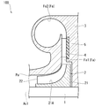
- the compressor 100 includes a rotating shaft 1, an impeller 2, a casing 3, a return vane 4, and an acoustic liner 5.
- the rotation axis 1 extends along the axis line Ac1 and can rotate around the axis line Ac1.
- An impeller 2 is fixed to the outer peripheral surface of the rotating shaft 1.
- the impeller 2 has a disk 21 and a plurality of blades 22.
- the disk 21 has a disk shape centered on the axis line Ac1.
- the outer peripheral surface (main surface 21A) of the disk 21 has a curved surface shape that curves from the inside to the outside in the radial direction from one side to the other side in the axis Ac1 direction.
- a plurality of blades 22 are provided on the main surface 21A at intervals in the circumferential direction. Although not shown in detail, each blade 22 is curved from the front side to the rear side in the rotation direction of the rotation shaft 1 from the inside to the outside in the radial direction. By rotating together with the rotation shaft 1, the impeller 2 pumps the fluid introduced from one side in the axis Ac1 direction toward the outside in the radial direction.
- the casing 3 surrounds the rotating shaft 1 and the impeller 2 from the outer peripheral side. Inside the casing 3, a compression flow path Pa that accommodates the impeller 2 and compresses a fluid guided from the outside, and an outlet flow path Fa that is connected to the radial outside of the compression flow path Pa are formed. There is.
- the diameter of the compressed flow path Pa gradually increases from one side in the axis Ac1 direction to the other side so as to correspond to the outer shape of the impeller 2.
- An outlet flow path Fa is connected to the radial outer outlet of the compression flow path Pa.
- the outlet flow path Fa has a diffuser flow path Fa1 and an outlet scroll Fa2.
- the diffuser flow path Fa1 is provided to recover the static pressure of the fluid derived from the compression flow path Pa.
- the diffuser flow path Fa1 has an annular shape extending outward in the radial direction from the outlet of the compression flow path Pa. In the cross-sectional view including the axis line Ac1, the flow path width of the diffuser flow path Fa1 is constant over the entire extending direction.
- a plurality of return vanes 4 are provided in the diffuser flow path Fa1. A plurality of these return vanes 4 are arranged at intervals in the circumferential direction.
- the outlet scroll Fa2 is connected to the radial outer outlet of the diffuser flow path Fa1.
- the exit scroll Fa2 has a spiral shape extending in the circumferential direction of the axis line Ac1.
- the exit scroll Fa2 has a circular flow path cross section.
- An exhaust hole for guiding the high-pressure fluid to the outside is formed in a part of the outlet scroll Fa2 (not shown).
- An acoustic liner 5 is provided on the wall surface on the other side of the above-mentioned diffuser flow path Fa1 in the direction of the axis Ac1.
- the acoustic liner 5 is embedded in the wall surface so as to face the diffuser flow path Fa1.
- the acoustic liner 5 has an annular shape centered on the axis Ac1.
- the acoustic liner 5 is provided to absorb and attenuate noise caused by a fluid flowing through the diffuser flow path Fa1.
- the acoustic liner 5 has a plate shape, and a plurality of introduction holes h to be opened in the diffuser flow path Fa1 are formed on one surface thereof. More specifically, as shown in FIG. 3, the acoustic liner 5 has an acoustic space V formed inside, an introduction hole h, and a vortex suppression structure 6.
- the acoustic space V is a space formed inside the acoustic liner 5.
- the introduction hole h communicates the diffuser flow path Fa1 with the acoustic space V.
- a vortex suppression structure 6 is provided in the connection region (throat portion S) between the introduction hole h and the acoustic space V.
- the vortex suppression structure 6 is provided to reduce / suppress vortices generated when sound waves flow into the acoustic space V from the introduction hole h.
- the foamed metal m as the vortex suppression structure 6 is provided so as to cover the introduction hole h from the acoustic space V side.
- the rotation shaft 1 is rotated around the axis line Ac1 by an external drive source.
- the impeller 2 also rotates with the rotation of the rotation shaft 1, whereby the external fluid is guided to the compression flow path Pa.
- the fluid guided to the blade 22 of the impeller 2 in the compression flow path Pa is compressed by centrifugal force and becomes a high pressure state.
- the high-pressure flow path is taken out to the outside via the diffuser flow path Fa1 and the outlet scroll Fa2.
- noise is generated due to the rotation of the impeller 2.
- noise called NZ noise tends to resonate with each part of the compressor 100, so it is important to reduce or suppress it.
- the NZ sound is noise (discrete frequency sound) having a frequency based on the integrated value of the number of blades (that is, the number of blades 22) N of the impeller 2 and the rotation speed Z of the rotating shaft 1.
- the acoustic liner 5 is provided in the diffuser flow path Fa1 for the purpose of reducing / suppressing such NZ sound.
- the sound wave introduced into the acoustic space V through the introduction hole h is attenuated in the acoustic space V. Thereby, it is possible to suppress the noise from leaking to the outside.
- the acoustic resistance becomes large when the sound wave is guided from the introduction hole h of the acoustic liner 5 to the acoustic space V. Specifically, a vortex is generated at the outlet of the introduction hole h (that is, the throat portion S), and this vortex hinders the smooth introduction of sound waves. As a result, a sufficient sound reduction effect may not be obtained.
- the vortex suppression structure 6 is provided in the throat portion S, the generation of vortices in the acoustic space V is suppressed. As a result, the resistance (acoustic resistance) when the sound wave flows into the introduction hole h is reduced. As a result, sound waves are easily introduced into the acoustic liner 5, so that noise can be absorbed and attenuated more efficiently.
- the foamed metal m as the vortex suppression structure 6 is provided so as to cover the introduction hole h. Since the vortices are separated by the foamed metal m, the resistance (acoustic resistance) when the sound wave flows into the introduction hole h can be further reduced. This makes it possible to further reduce the noise of the compressor 100.
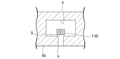
- a plurality of plate members 7 are provided in the throat portion S as the vortex suppression structure 6.
- a plurality of these plate members 7 extend from the introduction hole h toward the acoustic space V and are arranged at intervals in a direction including a surface orthogonal to the extension direction of the introduction hole h. As a result, a slit is formed between the plate materials.
- the vortices are separated when passing through the slit as the vortex suppression structure, so that the resistance (acoustic resistance) when the sound wave flows into the introduction hole can be reduced.
- the resistance acoustic resistance
- sound waves are easily introduced into the acoustic liner 5b, so that noise can be absorbed and attenuated more efficiently.
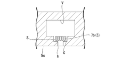
- a cavity C having an opening area larger than that of the introduction hole h is formed in a portion of the introduction hole h on the acoustic space V side.
- a plurality of plate members 7b similar to the above are arranged in the cavity C.
- a slit is formed between these plate members 7b.
- the vortices are separated when passing through the slit as the vortex suppression structure 6, so that the resistance (acoustic resistance) when the sound wave flows into the introduction hole h can be reduced. Further, since the plate material 7b forming the slit is housed in the cavity C, a large effective volume as the acoustic space V can be secured. Thereby, the noise can be further reduced.
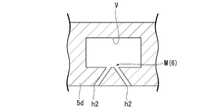
- a plurality of (two as an example) introduction holes h2 are formed in one acoustic space V. These plurality of introduction holes h2 extend so as to approach each other from the diffuser flow path Fa1 side toward the acoustic space V side.
- introduction holes h2 form a merging portion M as a vortex suppression structure 6 that suppresses vortices generated in the connection region between the plurality of introduction holes h2 and the acoustic space V by merging in the acoustic space V. ..
- the vortex suppression structure 6 is formed to reduce / suppress vortices generated when sound waves flow into the acoustic space V from the plurality of introduction holes h2.
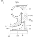
- the compressor 200 includes a rotating shaft 201, an impeller 202, a casing 203, and a diffuser vane 204.
- the rotating shaft 201 extends along the axis Ac2 and can rotate around the axis Ac2.
- An impeller 202 is fixed to the outer peripheral surface of the rotating shaft 201.
- the impeller 202 has a disk 221 and a plurality of blades 222.
- the disk 221 has a disk shape centered on the axis Ac2.
- the outer peripheral surface (main surface 221A) of the disk 221 has a curved surface shape that curves from the inside to the outside in the radial direction from one side to the other side in the axis Ac2 direction.
- a plurality of blades 222 are provided on the main surface 221A at intervals in the circumferential direction. Although not shown in detail, each blade 222 is curved from the front side to the rear side in the rotation direction of the rotation shaft 201 from the inside to the outside in the radial direction. By rotating together with the rotation shaft 201, the impeller 202 pumps the fluid introduced from one side in the axis Ac2 direction toward the outside in the radial direction.
- the casing 203 surrounds the rotating shaft 201 and the impeller 202 from the outer peripheral side.
- a compression flow path Pb for accommodating the impeller 202 and compressing a fluid guided from the outside and an outlet flow path Fb connected to the radial outside of the compression flow path Pb are formed inside the casing 203.
- the diameter of the compression flow path Pb gradually increases from one side in the axis Ac2 direction to the other side so as to correspond to the outer shape of the impeller 202.
- An outlet flow path Fb is connected to the radial outer outlet of the compression flow path Pb.
- the outlet flow path Fb has a diffuser flow path Fb1 and an outlet scroll Fb2.
- the diffuser flow path Fb1 is provided to recover the static pressure of the fluid guided from the compression flow path Pb.
- the diffuser flow path Fb1 has an annular shape extending radially outward from the outlet of the compression flow path Pb. In the cross-sectional view including the axis line Ac2, the flow path width of the diffuser flow path Fb1 is constant over the entire extending direction.
- a plurality of diffuser vanes 204 are provided in the diffuser flow path Fb1. The configuration of the diffuser vane 204 will be described later.
- the outlet scroll Fb2 is connected to the radial outer outlet of the diffuser flow path Fb1.
- the exit scroll Fb2 has a spiral shape extending in the circumferential direction of the axis line Ac2.
- the exit scroll Fb2 has a circular flow path cross section.
- An exhaust hole for guiding the high-pressure fluid to the outside is formed in a part of the outlet scroll Fb2 (not shown).
- a plurality of diffuser vanes 204 are arranged in the diffuser flow path Fb1 at intervals in the circumferential direction.
- Each diffuser vane 204 has a vane body 241 extending in the rotation direction of the rotation shaft 201 toward the outside in the radial direction, and a microacoustic structure 205 formed on the surface 241S of the vane body 241.
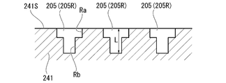
- the microacoustic structure 205 is a plurality of recesses 205R arranged at intervals on the surface 241S of the vane main body 241.
- Each recess 205R is recessed from the surface 241S toward the inside of the vane body 241.
- the portion of the recess 205R on the surface 241S side (entrance portion Ra) has a larger cross-sectional area than the other portion (bottom portion Rb).
- a step is formed between the entrance portion Ra and the bottom portion Rb.
- the cross-sectional area of the inlet Ra is constant over the entire extension length, and the cross-sectional area of the bottom Rb is also constant over the entire extension length.
- the rotating shaft 201 is rotated around the axis Ac2 by an external drive source.
- the impeller 202 also rotates with the rotation of the rotation shaft 201, whereby the external fluid is guided to the compression flow path Pb.
- the fluid guided to the blade 222 of the impeller 202 in the compression flow path Pb is compressed by centrifugal force and becomes a high pressure state.
- the high-pressure flow path is taken out to the outside via the diffuser flow path Fb1 and the outlet scroll Fb2.
- noise is generated due to the rotation of the impeller 202.
- noise called NZ noise tends to resonate with each part of the compressor 200, so it is important to reduce or suppress it.
- the NZ sound is noise (discrete frequency sound) having a frequency based on the value obtained by integrating the number of blades (that is, the number of blades 222) N of the impeller 202 and the rotation speed Z of the rotation shaft 201.
- the microacoustic structure 205 is provided on the vane main body 241 arranged in the outlet flow path Fb for the purpose of reducing / suppressing such NZ sound.
- noise can be absorbed and attenuated when the fluid passes through the surface 241S of the vane body 241.
- the reflection boundary condition is realized.
- Zi is the acoustic impedance
- ⁇ is the density
- c is the speed of sound.
- the portion of the recess 205R on the surface 241S side (entrance portion Ra) has a larger cross-sectional area than the other portion (bottom portion Rb).
- sound waves can be captured in a wider area of the surface 241S of the vane body 241.
- the fifth embodiment of the present disclosure will be described with reference to FIGS. 9 and 10.
- the same components as those in the fourth embodiment will be designated by the same reference numerals, and detailed description thereof will be omitted.
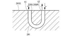
- a plurality of pipelines 205P are formed on the surface 241S of the vane main body 241. Both ends of the pipeline 205P are open to the surface 241S. That is, the pipeline 205P has a U shape in cross-sectional view.
- the sound wave is radiated from the other end t2 in a state where the phase of the sound wave is changed in the conduit 205P.
- the sound wave radiated from the other end t2 interferes with the sound wave incident on the other end t2, so that this can be attenuated.
- the length of the pipeline 205P is twice the wavelength of the sound to be reduced.
- the sound incident on the pipeline 205P from one end t1 (for example, the sound having a positive phase: the solid arrow in FIG. 10) is radiated as the sound having a negative phase from the other end t2.
- the sound of the + phase (broken line arrow in FIG. 10) entering the other end t2 can be canceled.
- the noise of the compressor 200 can be further reduced.
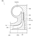
- the compressor 300 includes a rotating shaft 301, an impeller 302, a casing 303, a diffuser vane 304, a speaker wall 305, a pressure sensor Sp, and an arithmetic unit 90. ing.
- the rotating shaft 301 extends along the axis line Ac3 and is rotatable around the axis line Ac3.
- An impeller 302 is fixed to the outer peripheral surface of the rotating shaft 301.
- the impeller 302 has a disk 321 and a plurality of blades 322.
- the disk 321 has a disk shape centered on the axis Ac3.
- the outer peripheral surface (main surface 321A) of the disk 321 has a curved surface shape that curves from the inside to the outside in the radial direction from one side to the other side in the axis Ac3 direction.
- a plurality of blades 322 are provided on the main surface 321A at intervals in the circumferential direction. Although not shown in detail, each blade 322 is curved from the front side to the rear side in the rotation direction of the rotation shaft 301 from the inside to the outside in the radial direction. By rotating together with the rotation shaft 301, the impeller 302 pumps the fluid introduced from one side in the axis Ac3 direction toward the outside in the radial direction.
- the casing 303 surrounds the rotating shaft 301 and the impeller 302 from the outer peripheral side. Inside the casing 303, a compression flow path Pc for accommodating the impeller 302 and compressing a fluid guided from the outside and an outlet flow path Fc connected to the radial outside of the compression flow path Pc are formed. There is. The diameter of the compression flow path Pc gradually increases from one side in the axis Ac3 direction to the other side so as to correspond to the outer shape of the impeller 302. An outlet flow path Fc is connected to the radial outer outlet of the compression flow path Pc.
- the outlet flow path Fc has a diffuser flow path Fc1 and an outlet scroll Fc2.
- the diffuser flow path Fc1 is provided to recover the static pressure of the fluid derived from the compression flow path Pc.
- the diffuser flow path Fc1 has an annular shape extending radially outward from the outlet of the compression flow path Pc. In the cross-sectional view including the axis line Ac3, the flow path width of the diffuser flow path Fc1 is constant over the entire extending direction.
- a plurality of diffuser vanes 304 are provided in the diffuser flow path Fc1. A plurality of these diffuser vanes 304 are arranged at intervals in the circumferential direction.
- the outlet scroll Fc2 is connected to the radial outer outlet of the diffuser flow path Fc1.
- the exit scroll Fc2 has a spiral shape extending in the circumferential direction of the axis Ac3.
- the exit scroll Fc2 has a circular flow path cross section.
- An exhaust hole for guiding the high-pressure fluid to the outside is formed in a part of the outlet scroll Fc2 (not shown).
- a speaker wall 305 is provided on the wall surface on the other side of the above-mentioned diffuser flow path Fc1 in the direction of the axis Ac3.
- the speaker wall 305 is embedded in the wall surface so as to face the diffuser flow path Fc1.
- the speaker wall 305 forms an annular shape centered on the axis Ac3.
- the speaker wall 305 is provided to reduce noise caused by the fluid flowing through the diffuser flow path Fc1.
- the speaker wall 305 has a plate shape and has a plurality of speaker elements 351 arranged in the radial direction and the circumferential direction.
- An arithmetic unit 90 is connected to each speaker element 351 via a signal line.
- a pressure sensor Sp is provided below the speaker elements 351 (that is, on the upstream side of the speaker wall 305 in the diffuser flow path Fc1). The pressure sensor Sp detects the noise in the diffuser flow path Fc1 as a pressure fluctuation, and sends the detection result as an electric signal to the arithmetic unit 90.
- the computing device 90 causes the speaker element 351 to emit a sound (cancellation sound) having a frequency that cancels the target sound (that is, a sound having a frequency to be reduced) based on the detection value of the pressure sensor Sp. Send a signal.
- the arithmetic unit 90 includes a CPU 91 (Central Processing Unit), a ROM 92 (Read Only Memory), a RAM 93 (Random Access Memory), an HDD 94 (Hard Disk Drive), and a signal transmission / reception module 95 (I / O: Input). / Output).
- the signal transmission / reception module 95 receives the value of the pressure of the diffuser flow path Fc1 detected by the pressure sensor Sp described above as an electric signal. Further, the signal transmission / reception module 95 transmits an electric signal for producing the cancellation sound to the speaker element 351 described above.
- the signal transmission / reception module 95 may transmit / receive an amplified signal via, for example, a charge amplifier or the like.
- the CPU 91 of the arithmetic unit 90 executes a program stored in the own device in advance to execute the pressure acquisition unit 81, the frequency analysis unit 82, the antiphase generation unit 83, and the signal oscillation unit 84. And have.
- the pressure acquisition unit 81 receives the sound as the pressure value detected by the pressure sensor Sp.
- the frequency analysis unit 82 analyzes the frequency of the input sound and determines the frequency to be reduced.
- the anti-phase generation unit 83 generates a sound (cancelled sound) having a frequency having an anti-phase frequency of the target sound.
- the signal oscillation unit 84 outputs an electric signal to the speaker element 351 so that each speaker element 351 emits the canceling sound.
- the rotation shaft 301 is rotated around the axis line Ac3 by an external drive source.
- the impeller 302 also rotates with the rotation of the rotation shaft 301, whereby the external fluid is guided to the compression flow path Pc.
- the fluid guided to the blade 322 of the impeller 302 in the compression flow path Pc is compressed by centrifugal force and becomes a high pressure state.
- the high-pressure flow path is taken out to the outside via the diffuser flow path Fc1 and the outlet scroll Fc2.
- noise is generated due to the rotation of the impeller 302.
- noise called NZ noise tends to resonate with each part of the compressor 300, so it is important to reduce or suppress it.
- the NZ sound is noise (discrete frequency sound) having a frequency based on the value obtained by integrating the number of blades (that is, the number of blades 322) N of the impeller 302 and the rotation speed Z of the rotation shaft 301.
- the speaker wall 305 is provided in the diffuser flow path Fc1 for the purpose of reducing / suppressing such NZ sound.
- a sound having a frequency that cancels the sound as the pressure fluctuation detected by the pressure sensor Sp is emitted from the speaker wall 305.
- This sound can cancel the noise in the outlet flow path Fc.
- the pressure sensor Sp immediately catches it, and the arithmetic unit 90 generates a sound having a frequency for canceling the sound of the new frequency. As a result, it is possible to autonomously maintain a state in which noise is reduced regardless of the operating state of the compressor 300.
- the frequency analysis unit 82 determines the target sound based on the detection value of the pressure sensor Sp, and the anti-phase generation unit 83 produces a sound having a frequency opposite to the frequency of this sound. Generate.
- the signal oscillator 84 transmits a signal to the speaker wall 305 so as to output the sound having the opposite phase. Thereby, the noise of a specific frequency can be selectively and effectively reduced.
- cancellation sounds having different frequencies are emitted from the plurality of speaker elements 351b of the speaker wall 305b.
- the anti-phase generation unit 83 generates a plurality of anti-phase frequency cancellation sounds corresponding to the target sound of the plurality of frequencies.
- the signal oscillating unit 84 sends a signal to each speaker element 351b so as to emit a canceling sound having a frequency of any opposite phase. For example, a specific speaker element 351b emits a canceling sound of 2 kHz, and another speaker element 351b different from this emits a cancel sound of 2.1 kHz.
- the anti-phase generation unit 83 generates sounds having opposite-phase frequencies corresponding to each of the target sounds having a plurality of frequencies.
- the signal oscillating unit 84 oscillates any one of the plurality of sounds having frequencies having opposite phases from the respective speaker elements 351b. Therefore, the noise generated in the outlet flow path Fc can be reduced in all frequency bands. As a result, the noise of the compressor 300 can be further suppressed.
- one acoustic liner 5 is applied in combination with the configurations of a plurality of different types of vortex suppression structures 6 described in the first to third embodiments and the introduction hole h2 described in the third embodiment. It is also possible.
- the compressors 100, 200, and 300 described in each embodiment are grasped as follows, for example.
- the compressor 100 pumps a fluid from one side in the axis Ac1 direction to the outside in the radial direction by rotating together with the rotating shaft 1 that rotates around the axis Ac1 and the rotating shaft 1.
- the casing 3 which surrounds the rotating shaft 1 and the impeller 2 and has an outlet flow path Fa for guiding the fluid pumped from the impeller 2, and the outlet flow path Fa in the casing 3.
- the acoustic liner 5 is provided so as to face the acoustic liner 5, and the acoustic liner 5 is introduced so as to communicate the acoustic space V formed in the acoustic liner 5 with the outlet flow path Fa. It has a hole h and a vortex suppression structure 6 provided in a connection region between the introduction hole h and the acoustic space V to suppress a vortex generated in the connection region.
- the vortex suppression structure 6 since the vortex suppression structure 6 is provided, the generation of vortices in the acoustic space V is suppressed. As a result, the resistance (acoustic resistance) when the sound wave flows into the introduction hole h is reduced. As a result, the acoustic liner 5 can absorb and attenuate sound waves more efficiently.
- the vortex suppression structure 6 is a foamed metal m that covers the introduction hole h in the acoustic space V.
- the foamed metal m as the vortex suppression structure 6 is provided so as to cover the introduction hole h. Since the vortices are separated by the foamed metal m, the resistance (acoustic resistance) when the sound wave flows into the introduction hole h can be reduced.
- the vortex suppression structure 6 is a plurality of slits formed of a plurality of plate members 7 extending from the introduction hole h toward the acoustic space V.
- the vortices are separated when passing through the slit as the vortex suppression structure 6, so that the resistance (acoustic resistance) when the sound wave flows into the introduction hole h can be reduced.
- a cavity C having an opening area larger than that of the introduction hole h is formed in the portion of the introduction hole h on the acoustic space V side, and the vortex suppression structure is formed.
- Reference numeral 6 denotes a plurality of slits arranged in the cavity C and formed of a plurality of plate members 7b extending from the introduction hole h toward the acoustic space V.
- the vortices are separated when passing through the slit as the vortex suppression structure 6, so that the resistance (acoustic resistance) when the sound wave flows into the introduction hole h can be reduced. Further, since the plate material 7b forming the slit is housed in the cavity C, a large effective volume as the acoustic space V can be secured. Thereby, the noise can be further reduced.
- the compressor 100 pumps fluid from one side in the axis Ac1 direction to the outside in the radial direction by rotating together with the rotating shaft 1 that rotates around the axis Ac1 and the rotating shaft 1.
- the casing 3 which surrounds the rotating shaft 1 and the impeller 2 and has an outlet flow path Fa for guiding the fluid pumped from the impeller 2, and the outlet flow path Fa in the casing 3.
- a plurality of acoustic liners 5d provided so as to face the surface of the acoustic liner 5 are provided, and the acoustic liner 5 communicates the acoustic space V formed in the acoustic liner 5 and the acoustic space V with the outlet flow path Fa.
- the plurality of introduction holes h2 are formed so as to be close to each other and connected to the acoustic space V from the outlet flow path Fa toward the acoustic space V, and the plurality of introduction holes h2 are provided.
- a vortex suppression structure 6 that suppresses a vortex generated in the connection region between the hole h2 and the acoustic space V is formed.
- the compressor 200 pumps a fluid from one side in the axis Ac2 direction to the outside in the radial direction by rotating together with the rotating shaft 201 that rotates around the axis Ac2 and the rotating shaft 201.
- the casing 203 and the diffuser flow path Fb1 which surround the rotating shaft 201 and the impeller 202 and have a diffuser flow path Fb1 for guiding the fluid pumped from the impeller 202 outward in the radial direction.
- a plurality of diffuser vanes 204 provided at intervals in the circumferential direction of the axis line Ac2 are provided, and the diffuser vanes 204 extend in the rotational direction of the rotary shaft 201 as they go outward in the radial direction.
- a microacoustic structure 205 formed on the surface 241S of the vane body 241.
- the microacoustic structure 205 is formed on the surface 241S of the vane body 241. As a result, noise can be absorbed and attenuated when the fluid passes through the surface 241S of the vane body 241.
- the microacoustic structure 205 is composed of a plurality of recesses 205R recessed from the surface 241S of the vane body 241.
- the depth of the recess 205R from the surface 241S is one-fourth the length of the target sound wavelength.
- the portion of the recess 205R on the surface 241S side has a larger cross-sectional area than the other portions.
- the portion of the recess 205R on the surface 241S side has a larger cross-sectional area than the other portions.
- the cross-sectional area of the entrance of the recess 205R is larger than the cross-sectional area of the bottom.
- the microacoustic structure 205 is composed of a plurality of pipelines 205P having both ends open on the surface 241S of the vane main body 241.
- the sound wave is radiated from the other end in a state where the phase of the sound wave is changed in the conduit 205P.
- the sound wave radiated from the other end interferes with the sound wave incident on the other end, so that this can be attenuated.
- the length of the pipeline 205P from one end to the other end is twice as long as the target sound wavelength.
- the length of the pipeline 205P is twice the wavelength of the sound to be reduced.
- the sound (phase is +) incident on the conduit 205P from one end is radiated as a sound having a negative phase from the other end.
- the sound of the + phase entering the other end can be canceled.
- the compressor 300 pumps a fluid from one side in the axis Ac3 direction to the outside in the radial direction by rotating together with the rotating shaft 301 that rotates around the axis Ac3 and the rotating shaft 301.
- the casing 303 which surrounds the rotating shaft 301 and the impeller 302, and has an outlet flow path Fc for guiding the fluid pumped from the impeller 302, and the outlet flow path Fc in the casing 303.
- the pressure sensor Sp Based on the speaker wall 305 provided so as to face the surface, the pressure sensor Sp that detects the pressure in the outlet flow path Fc, and the detection value of the pressure sensor Sp, a sound having a frequency that cancels the target sound is produced.
- a computing device 90 that sends a signal to the speaker wall 305 so as to emit a signal is provided.
- a sound having a frequency that cancels the sound as a pressure fluctuation detected by the pressure sensor Sp is emitted from the speaker wall 305.
- This sound can cancel the noise in the outlet flow path Fc.
- the pressure sensor Sp immediately catches it, and the arithmetic unit 90 generates a sound having a frequency for canceling the sound of the new frequency.
- noise can be autonomously reduced regardless of the operating state of the compressor 300.
- the arithmetic unit 90 is subjected to frequency analysis on the detected value of the pressure sensor Sp and decomposed into each frequency by the frequency analysis unit 82 and the frequency analysis unit 82.
- the antiphase generation unit 83 that generates a frequency that is opposite in phase to the frequency of the target sound, and the speaker so that the sound of the frequency generated by the antiphase generation unit 83 is output. It has a signal oscillating unit 84 that sends a signal to the wall 305.
- the frequency analysis unit 82 determines the target sound based on the detection value of the pressure sensor Sp, and the anti-phase generation unit 83 generates a sound having a frequency opposite to the frequency of this sound. do.
- the signal oscillator 84 transmits a signal to the speaker wall 305 so as to output the sound having the opposite phase. Thereby, the noise of a specific frequency can be selectively and effectively reduced.
- the speaker wall 305 has a plurality of speaker elements 351b
- the anti-phase generation unit 83 has a plurality of inverses corresponding to a plurality of target sounds.
- a phase frequency is generated, and the signal oscillating unit 84 sends a signal to the plurality of speaker elements 351b so as to emit a sound having a frequency having one of the opposite phases.
- the anti-phase generation unit 83 generates sounds of opposite-phase frequencies corresponding to the sounds of a plurality of target frequencies.
- the signal oscillating unit 84 oscillates any one of the plurality of sounds having frequencies having opposite phases from the respective speaker elements 351b. Therefore, the noise generated in the outlet flow path Fc can be reduced in all frequency bands.
Landscapes
- Engineering & Computer Science (AREA)
- Mechanical Engineering (AREA)
- General Engineering & Computer Science (AREA)
- Physics & Mathematics (AREA)
- Acoustics & Sound (AREA)
- Signal Processing (AREA)
- Multimedia (AREA)
- Structures Of Non-Positive Displacement Pumps (AREA)
Abstract
圧縮機(100)は、軸線回りに回転する回転軸(1)と、流体を圧送するインペラ(2)と、回転軸及びインペラを囲うとともに、インペラから圧送される流体を導く出口流路が形成されたケーシング(3)と、ケーシングにおける出口流路内に面するように設けられた音響ライナ(5)と、を備え、音響ライナは、音響空間(V)と、音響空間を出口流路に連通させる導入孔(h)と、導入孔と音響空間との接続領域に設けられて、接続領域で発生する渦を抑制する渦抑制構造(6)と、を有する。
Description
本開示は、圧縮機に関する。
本願は、2020年3月16日に日本国特許庁に出願された特願2020-045777号、2020年3月16日に日本国特許庁に出願された特願2020-045783号、及び2020年3月16日に日本国特許庁に出願された特願2020-045650号に対して優先権を主張し、その内容をここに援用する。
本願は、2020年3月16日に日本国特許庁に出願された特願2020-045777号、2020年3月16日に日本国特許庁に出願された特願2020-045783号、及び2020年3月16日に日本国特許庁に出願された特願2020-045650号に対して優先権を主張し、その内容をここに援用する。
圧縮機を含むターボ機械では、回転部品の回転に伴って騒音が発生する。このような騒音が静止部品に伝播すると、当該静止部品の構造破壊を引き起こす虞がある。そこで、騒音防止を目的として、圧縮機の出口流路中に音響ライナを設ける構成が提唱されている(下記特許文献1)。この音響ライナは、流路に向かって開口する導入孔と、この導入孔の下流側に接続された音響空間とを有している。
しかしながら、上記のような圧縮機では流路内の流速が高いため、音響ライナの導入孔から音響空間に音波を導くに当たって、音響抵抗が大きくなっている。具体的には、導入孔の出口(つまり、音響空間の入口)で渦が発生し、この渦によって音波の円滑な導入が妨げられてしまう。その結果、十分な音響低減効果が得られない可能性がある。
本開示は上記課題を解決するためになされたものであって、騒音がより一層低減された圧縮機を提供することを目的とする。
上記課題を解決するために、本開示に係る圧縮機は、軸線回りに回転する回転軸と、該回転軸とともに回転することで、軸線方向一方側から径方向外側に向かって流体を圧送するインペラと、前記回転軸及び前記インペラを囲うとともに、前記インペラから圧送される前記流体を導く出口流路が形成されたケーシングと、前記ケーシングにおける前記出口流路内に面するように設けられた音響ライナと、を備え、前記音響ライナは、該音響ライナ内に形成された音響空間と、該音響空間を前記出口流路に連通させる導入孔と、前記導入孔と前記音響空間との接続領域に設けられて、該接続領域で発生する渦を抑制する渦抑制構造と、を有する。
本開示に係る圧縮機は、軸線回りに回転する回転軸と、該回転軸とともに回転することで、軸線方向一方側から径方向外側に向かって流体を圧送するインペラと、前記回転軸及び前記インペラを囲うとともに、前記インペラから圧送される前記流体を導く出口流路が形成されたケーシングと、前記ケーシングにおける前記出口流路内に面するように設けられた音響ライナと、を備え、該音響ライナは、該音響ライナ内に形成された音響空間と、該音響空間を前記出口流路に連通させる複数の導入孔と、を有し、これら複数の導入孔は、前記出口流路から前記音響空間に向かうに従って互いに近接して前記音響空間につながるように形成され、前記複数の導入孔と前記音響空間との接続領域で発生する渦を抑制する渦抑制構造を形成している。
本開示に係る圧縮機は、軸線回りに回転する回転軸と、該回転軸とともに回転することで、軸線方向一方側から径方向外側に向かって流体を圧送するインペラと、前記回転軸及び前記インペラを囲うとともに、前記インペラから圧送される前記流体を径方向外側に導くディフューザ流路が形成されたケーシングと、前記ディフューザ流路に、前記軸線の周方向に間隔をあけて複数設けられたディフューザベーンと、を備え、前記ディフューザベーンは、径方向外側に向かうに従って前記回転軸の回転方向に向かって延びるベーン本体と、該ベーン本体の表面に形成された微小音響構造と、を有する。
本開示に係る圧縮機は、軸線回りに回転する回転軸と、該回転軸とともに回転することで、軸線方向一方側から径方向外側に向かって流体を圧送するインペラと、前記回転軸及び前記インペラを囲うとともに、前記インペラから圧送される前記流体を導く出口流路が形成されたケーシングと、前記ケーシングにおける前記出口流路内に面するように設けられたスピーカ壁と、前記出口流路内の圧力を検出する圧力センサと、前記圧力センサの検出値に基づいて、目標とする音を打ち消す周波数の音を発するように前記スピーカ壁に信号を送る演算装置と、を備える。
本開示によれば、騒音がより一層低減された圧縮機を提供することができる。
[第一実施形態]
(圧縮機の構成)
以下、本開示の第一実施形態に係る圧縮機100について、図1から図3を参照して説明する。図1に示すように、圧縮機100は、回転軸1と、インペラ2と、ケーシング3と、リターンベーン4と、音響ライナ5と、を備えている。
回転軸1は、軸線Ac1に沿って延びるとともに、当該軸線Ac1回りに回転可能である。回転軸1の外周面には、インペラ2が固定されている。インペラ2は、ディスク21と、複数のブレード22と、を有している。ディスク21は、軸線Ac1を中心とする円盤状をなしている。ディスク21の外周面(主面21A)は、軸線Ac1方向一方側から他方側に向かうに従って径方向内側から外側に向かって湾曲する曲面状をなしている。
この主面21A上には、周方向に間隔をあけて複数のブレード22が設けられている。詳しくは図示しないが、各ブレード22は、径方向内側から外側に向かうに従って、回転軸1の回転方向前方側から後方側に向かって湾曲している。インペラ2は、回転軸1とともに回転することで、軸線Ac1方向一方側から導入された流体を径方向外側に向かって圧送する。
ケーシング3は、これら回転軸1、及びインペラ2を外周側から囲っている。ケーシング3の内部には、インペラ2を収容するとともに外部から導かれた流体を圧縮する圧縮流路Paと、圧縮流路Paの径方向外側に接続された出口流路Faと、が形成されている。圧縮流路Paは、インペラ2の外形に対応するように、軸線Ac1方向一方側から他方側に向かうに従って次第に拡径している。圧縮流路Paの径方向外側の出口には出口流路Faが接続されている。
出口流路Faは、ディフューザ流路Fa1と、出口スクロールFa2と、を有している。ディフューザ流路Fa1は、圧縮流路Paから導かれた流体の静圧を回復させるために設けられている。ディフューザ流路Fa1は、圧縮流路Paの出口から径方向外側に向かって延びる円環状をなしている。軸線Ac1を含む断面視では、ディフューザ流路Fa1の流路幅は延在方向の全域にわたって一定である。ディフューザ流路Fa1中には複数のリターンベーン4が設けられている。これらリターンベーン4は、周方向に間隔をあけて複数配列されている。
ディフューザ流路Fa1の径方向外側の出口には、出口スクロールFa2が接続されている。出口スクロールFa2は、軸線Ac1の周方向に延びる渦巻き状をなしている。出口スクロールFa2は、円形の流路断面を有している。出口スクロールFa2の一部には、高圧流体を外部に導くための排気孔が形成されている(図示省略)。
(音響ライナの構成)
上述のディフューザ流路Fa1における軸線Ac1方向他方側の壁面には、音響ライナ5が設けられている。音響ライナ5は、ディフューザ流路Fa1に面するように、この壁面内に埋設されている。音響ライナ5は、軸線Ac1を中心とする円環状をなしている。音響ライナ5は、ディフューザ流路Fa1中を流通する流体による騒音を吸収・減衰させるために設けられている。
図2に示すように、音響ライナ5は板状をなし、その一方側の面にはディフューザ流路Fa1内に開孔する複数の導入孔hが形成されている。より詳細には、図3に示すように、音響ライナ5は、内部に形成された音響空間Vと、導入孔hと、渦抑制構造6と、を有している。
音響空間Vは、音響ライナ5の内部に形成された空間である。導入孔hは、ディフューザ流路Fa1と音響空間Vとを連通している。音響ライナ5の内部には、このような音響空間V及び導入孔hの対が、延在面積の全域にわたって複数形成されている。
導入孔hと音響空間Vとの接続領域(スロート部S)には、渦抑制構造6が設けられている。渦抑制構造6は、導入孔hから音響空間V内に向かって音波が流入する際に発生する渦を低減・抑制するために設けられている。本実施形態では、渦抑制構造6としての発泡金属mが、導入孔hを音響空間V側から覆うようにして設けられている。
(作用効果)
次に、圧縮機100の動作について説明する。圧縮機100を運転するに当たっては、まず外部の駆動源によって回転軸1を軸線Ac1回りに回転させる。回転軸1の回転に伴ってインペラ2も回転し、これにより外部の流体が圧縮流路Paに導かれる。圧縮流路Pa中でインペラ2のブレード22に案内された流体は遠心力によって圧縮されて高圧状態となる。この高圧状態の流路は、ディフューザ流路Fa1、及び出口スクロールFa2を経て外部に取り出される。
ここで、上記のような圧縮機100では、インペラ2の回転に伴う騒音が発生する。このような騒音のうち、特にNZ音と呼ばれる騒音は、圧縮機100の各部と共振を起こしやすいことから、その低減・抑制が肝要である。NZ音とは、インペラ2の羽根枚数(つまり、ブレード22の数)Nと、回転軸1の回転数Zとを積算した値に基づく周波数の騒音(離散周波数音)である。
このようなNZ音の低減・抑制を目的として、本実施形態ではディフューザ流路Fa1に音響ライナ5が設けられている。導入孔hを通じて音響空間V内に導入された音波は、当該音響空間V内で減衰する。これにより、騒音が外部に漏れることを抑制することができる。
ところで、上記のようなディフューザ流路Fa1では流体の流速が高いため、音響ライナ5の導入孔hから音響空間Vに音波を導くに当たって、音響抵抗が大きくなっている。具体的には、導入孔hの出口(つまり、スロート部S)で渦が発生し、この渦によって音波の円滑な導入が妨げられてしまう。その結果、十分な音響低減効果が得られない可能性がある。
しかしながら、上記構成によれば、スロート部Sに渦抑制構造6が設けられていることから、音響空間V内における渦の発生が抑制される。これにより、導入孔hに音波が流れ込む際の抵抗(音響抵抗)が低減される。その結果、音響ライナ5に音波が導入されやすくなるため、より効率的に騒音を吸収・減衰させることができる。
特に、上記構成では、渦抑制構造6としての発泡金属mが導入孔hを覆うように設けられている。発泡金属mによって渦が離散することで、導入孔hに音波が流れ込む際の抵抗(音響抵抗)をより一層低減することができる。これにより、圧縮機100の騒音をより一層低減することが可能となる。
[第二実施形態]
続いて、本開示の第二実施形態について、図4を参照して説明する。なお、上記の第一実施形態と同様の構成については同一の符号を付し、詳細な説明を省略する。同図に示すように、本実施形態に係る音響ライナ5bでは、渦抑制構造6として、スロート部Sに複数の板材7が設けられている。これら板材7は、導入孔hから音響空間Vに向かって延びるとともに、導入孔hの延びる方向に直交する面を含む方向に間隔をあけて複数配列されている。これにより、板材同士の間にはスリットが形成されている。
上記構成によれば、渦抑制構造としてのスリットを通過する際に渦が離散することで、導入孔に音波が流れ込む際の抵抗(音響抵抗)を低減することができる。その結果、音響ライナ5bに音波が導入されやすくなるため、より効率的に騒音を吸収・減衰させることができる。
なお、第二実施形態の変形例として、図5に示す構成を採ることも可能である。同図の音響ライナ5cでは、導入孔hにおける音響空間V側の部分に、当該導入孔hよりも大きな開孔面積を有するキャビティCが形成されている。このキャビティC内には、上記と同様の複数の板材7bが配列されている。これら板材7b同士の間にはスリットが形成されている。
上記構成によれば、渦抑制構造6としてのスリットを通過する際に渦が離散することで、導入孔hに音波が流れ込む際の抵抗(音響抵抗)を低減することができる。また、スリットを形成する板材7bがキャビティC内に収容されていることから、音響空間Vとして有効な体積を大きく確保することができる。これにより、騒音をより一層低減することができる。
[第三実施形態]
続いて、本開示の第三実施形態について、図6を参照して説明する。なお、上記の各実施形態と同様の構成については同一の符号を付し、詳細な説明を省略する。同図に示すように、本実施形態に係る音響ライナ5dでは、1つの音響空間Vに対して複数(一例として2つ)の導入孔h2が形成されている。これら複数の導入孔h2は、ディフューザ流路Fa1側から音響空間V側に向かうに従って互いに近接するように延びている。これら導入孔h2は、音響空間V内で合流することで、複数の導入孔h2と音響空間Vとの接続領域で発生する渦を抑制する渦抑制構造6としての合流部Mを形成している。渦抑制構造6は、複数の導入孔h2から音響空間V内に向かって音波が流入する際に発生する渦を低減・抑制するために形成されている。
上記構成によれば、複数の導入孔h2から導かれた音波同士が音響空間V内に流入する際に互いに干渉する。これにより、渦の発生が抑制され、導入孔h2に音波が流れ込む際の抵抗(音響抵抗)が低減される。その結果、音響ライナ5dに音波が導入されやすくなるため、より効率的に騒音を吸収・減衰させることができる。
[第四実施形態]
(圧縮機の構成)
続いて、本開示の第四実施形態に係る圧縮機200について、図7と図8を参照して説明する。図7に示すように、圧縮機200は、回転軸201と、インペラ202と、ケーシング203と、ディフューザベーン204と、を備えている。
回転軸201は、軸線Ac2に沿って延びるとともに、当該軸線Ac2回りに回転可能である。回転軸201の外周面には、インペラ202が固定されている。インペラ202は、ディスク221と、複数のブレード222と、を有している。ディスク221は、軸線Ac2を中心とする円盤状をなしている。ディスク221の外周面(主面221A)は、軸線Ac2方向一方側から他方側に向かうに従って径方向内側から外側に向かって湾曲する曲面状をなしている。
この主面221A上には、周方向に間隔をあけて複数のブレード222が設けられている。詳しくは図示しないが、各ブレード222は、径方向内側から外側に向かうに従って、回転軸201の回転方向前方側から後方側に向かって湾曲している。インペラ202は、回転軸201とともに回転することで、軸線Ac2方向一方側から導入された流体を径方向外側に向かって圧送する。
ケーシング203は、これら回転軸201、及びインペラ202を外周側から囲っている。ケーシング203の内部には、インペラ202を収容するとともに外部から導かれた流体を圧縮する圧縮流路Pbと、圧縮流路Pbの径方向外側に接続された出口流路Fbと、が形成されている。圧縮流路Pbは、インペラ202の外形に対応するように、軸線Ac2方向一方側から他方側に向かうに従って次第に拡径している。圧縮流路Pbの径方向外側の出口には出口流路Fbが接続されている。
出口流路Fbは、ディフューザ流路Fb1と、出口スクロールFb2と、を有している。ディフューザ流路Fb1は、圧縮流路Pbから導かれた流体の静圧を回復させるために設けられている。ディフューザ流路Fb1は、圧縮流路Pbの出口から径方向外側に向かって延びる円環状をなしている。軸線Ac2を含む断面視では、ディフューザ流路Fb1の流路幅は延在方向の全域にわたって一定である。ディフューザ流路Fb1中には複数のディフューザベーン204が設けられている。ディフューザベーン204の構成については後述する。
ディフューザ流路Fb1の径方向外側の出口には、出口スクロールFb2が接続されている。出口スクロールFb2は、軸線Ac2の周方向に延びる渦巻き状をなしている。出口スクロールFb2は、円形の流路断面を有している。出口スクロールFb2の一部には、高圧流体を外部に導くための排気孔が形成されている(図示省略)。
(ディフューザベーンの構成)
ディフューザベーン204は、ディフューザ流路Fb1中で、周方向に間隔をあけて複数配列されている。各ディフューザベーン204は、径方向外側に向かうに従って回転軸201の回転方向に向かって延びるベーン本体241と、ベーン本体241の表面241Sに形成された微小音響構造205と、を有する。
図8に示すように、本実施形態に係る微小音響構造205は、ベーン本体241の表面241S上で互いに間隔をあけて配列された複数の凹部205Rである。各凹部205Rは、表面241Sからベーン本体241の内部に向かって凹んでいる。凹部205Rの表面241S側の部分(入口部Ra)は、他の部分(底部Rb)に比べて断面積が大きい。また、入口部Raと底部Rbとの間には段差が形成されている。入口部Raの断面積は延在長さの全域にわたって一定であり、底部Rbの断面積も延在長さの全域にわたって一定である。
凹部205Rの表面241Sからの深さL(つまり、入口部Raと底部Rbの長さの和)は、低減対象となる音の波長λの4分の1の長さである。つまり、L=(1/4)×λとされている。
(作用効果)
次に、圧縮機200の動作について説明する。圧縮機200を運転するに当たっては、まず外部の駆動源によって回転軸201を軸線Ac2回りに回転させる。回転軸201の回転に伴ってインペラ202も回転し、これにより外部の流体が圧縮流路Pbに導かれる。圧縮流路Pb中でインペラ202のブレード222に案内された流体は遠心力によって圧縮されて高圧状態となる。この高圧状態の流路は、ディフューザ流路Fb1、及び出口スクロールFb2を経て外部に取り出される。
ここで、上記のような圧縮機200では、インペラ202の回転に伴う騒音が発生する。このような騒音のうち、特にNZ音と呼ばれる騒音は、圧縮機200の各部と共振を起こしやすいことから、その低減・抑制が肝要である。NZ音とは、インペラ202の羽根枚数(つまり、ブレード222の数)Nと、回転軸201の回転数Zとを積算した値に基づく周波数の騒音(離散周波数音)である。
このようなNZ音の低減・抑制を目的として、本実施形態では出口流路Fbに配置されたベーン本体241に微小音響構造205が設けられている。これにより、ベーン本体241の表面241Sを流体が通過する際に、騒音を吸収・減衰させることができる。
さらに、上記構成によれば、微小音響構造205としての凹部205Rに音波が捕捉され、当該凹部205R内で減衰する。これにより、騒音が外部に漏れることを低減することができる。
また、上記構成によれば、凹部205Rの表面241Sからの深さLを、低減対象となる周波数の音の波長λの4分の1とすることで、凹部205Rの入口でZi=ρcの無反射境界条件が実現される。なお、Ziは音響インピーダンスであり、ρは密度、cは音速である。これにより、凹部205Rに捕捉された当該低減対象の周波数の音波を、外部に反射させずに減衰させることができる。
上記構成によれば、凹部205Rの表面241S側の部分(入口部Ra)は、他の部分(底部Rb)に比べて断面積が大きい。これにより、ベーン本体241の表面241Sのより広い領域で音波を捕捉することができる。
[第五実施形態]
続いて、本開示の第五実施形態について、図9と図10を参照して説明する。なお、上記の第四実施形態と同様の構成については同一の符号を付し、詳細な説明を省略する。図9に示すように、本実施形態では微小音響構造205として、ベーン本体241の表面241Sに複数の管路205Pが形成されている。管路205Pは、両端が表面241Sに開口している。つまり、管路205Pは、断面視でU字状をなしている。管路205Pの長さLp(つまり、一端t1から他端t2までの長さ)は、低減対象となる音の波長λの2倍に設定されている(Lp=2×λ)。
上記構成によれば、管路205Pの一端t1から音波を導入することによって、当該管路205P内で音波の位相が変わった状態で、他端t2から放射される。この他端t2から放射される音波が、当該他端t2に入射する音波と干渉することで、これを減衰させることができる。
特に、上記構成によれば、管路205Pの長さは、低減対象の音の波長の2倍とされている。これにより、一端t1から管路205Pに入射する音(たとえば位相が+の音:図10中の実線矢印)は、他端t2から-の位相の音として放射されることになる。これにより、他端t2に入ってくる+の位相の音(図10中の破線矢印)を打ち消すことができる。その結果、圧縮機200の騒音をより一層低減することができる。
[第六実施形態]
(圧縮機の構成)
続いて、本開示の第六実施形態に係る圧縮機300について、図11~図13を参照して説明する。図11又は図12に示すように、圧縮機300は、回転軸301と、インペラ302と、ケーシング303と、ディフューザベーン304と、スピーカ壁305と、圧力センサSpと、演算装置90と、を備えている。
図11に示すように、回転軸301は、軸線Ac3に沿って延びるとともに、当該軸線Ac3回りに回転可能である。回転軸301の外周面には、インペラ302が固定されている。インペラ302は、ディスク321と、複数のブレード322と、を有している。ディスク321は、軸線Ac3を中心とする円盤状をなしている。ディスク321の外周面(主面321A)は、軸線Ac3方向一方側から他方側に向かうに従って径方向内側から外側に向かって湾曲する曲面状をなしている。
この主面321A上には、周方向に間隔をあけて複数のブレード322が設けられている。詳しくは図示しないが、各ブレード322は、径方向内側から外側に向かうに従って、回転軸301の回転方向前方側から後方側に向かって湾曲している。インペラ302は、回転軸301とともに回転することで、軸線Ac3方向一方側から導入された流体を径方向外側に向かって圧送する。
ケーシング303は、これら回転軸301、及びインペラ302を外周側から囲っている。ケーシング303の内部には、インペラ302を収容するとともに外部から導かれた流体を圧縮する圧縮流路Pcと、圧縮流路Pcの径方向外側に接続された出口流路Fcと、が形成されている。圧縮流路Pcは、インペラ302の外形に対応するように、軸線Ac3方向一方側から他方側に向かうに従って次第に拡径している。圧縮流路Pcの径方向外側の出口には出口流路Fcが接続されている。
出口流路Fcは、ディフューザ流路Fc1と、出口スクロールFc2と、を有している。ディフューザ流路Fc1は、圧縮流路Pcから導かれた流体の静圧を回復させるために設けられている。ディフューザ流路Fc1は、圧縮流路Pcの出口から径方向外側に向かって延びる円環状をなしている。軸線Ac3を含む断面視では、ディフューザ流路Fc1の流路幅は延在方向の全域にわたって一定である。ディフューザ流路Fc1中には複数のディフューザベーン304が設けられている。これらディフューザベーン304は、周方向に間隔をあけて複数配列されている。
ディフューザ流路Fc1の径方向外側の出口には、出口スクロールFc2が接続されている。出口スクロールFc2は、軸線Ac3の周方向に延びる渦巻き状をなしている。出口スクロールFc2は、円形の流路断面を有している。出口スクロールFc2の一部には、高圧流体を外部に導くための排気孔が形成されている(図示省略)。
(スピーカ壁の構成)
上述のディフューザ流路Fc1における軸線Ac3方向他方側の壁面には、スピーカ壁305が設けられている。スピーカ壁305は、ディフューザ流路Fc1に面するように、この壁面内に埋設されている。スピーカ壁305は、軸線Ac3を中心とする円環状をなしている。スピーカ壁305は、ディフューザ流路Fc1中を流通する流体による騒音を低減するために設けられている。
図12に示すように、スピーカ壁305は板状をなすとともに、径方向及び周方向に配列された複数のスピーカ素子351を有している。各スピーカ素子351には、信号線を介して演算装置90が接続されている。また、これらスピーカ素子351の下方(つまり、ディフューザ流路Fc1におけるスピーカ壁305の上流側)には、圧力センサSpが設けられている。圧力センサSpは、ディフューザ流路Fc1内の騒音を圧力変動として検出して、検出結果を電気信号として演算装置90に送出する。
(演算装置の構成)
演算装置90は、圧力センサSpの検出値に基づいて、対象とする音(つまり、低減の対象となる周波数を有する音)を打ち消す周波数の音(キャンセル音)を発するように、スピーカ素子351に信号を送る。
図13に示すように、演算装置90は、CPU91(Central Processing Unit)、ROM92(Read Only Memory)、RAM93(Random Access Memory)、HDD94(Hard Disk Drive)、信号送受信モジュール95(I/O:Input/Output)を備えるコンピュータである。信号送受信モジュール95は、上述の圧力センサSpが検出したディフューザ流路Fc1の圧力の値を電気信号として受信する。また、信号送受信モジュール95は、上述のスピーカ素子351に、上記のキャンセル音を出させるための電気信号を送信する。なお、信号送受信モジュール95は、例えばチャージアンプ等を介して増幅された信号を送受信してもよい。
図14に示すように、演算装置90のCPU91は、予め自装置で記憶するプログラムを実行することにより、圧力取得部81と、周波数分析部82と、逆位相生成部83と、信号発振部84と、を有する。圧力取得部81は、圧力センサSpが検出した圧力値としての音を受信する。周波数分析部82は、入力された音の周波数を分析し、低減の対象となる周波数を決定する。逆位相生成部83は、対象となる音の逆位相の周波数を有する音(キャンセル音)を生成する。信号発振部84は、当該キャンセル音を各スピーカ素子351が出すようにスピーカ素子351に電気信号を出力する。
(作用効果)
次に、圧縮機300の動作について説明する。圧縮機300を運転するに当たっては、まず外部の駆動源によって回転軸301を軸線Ac3回りに回転させる。回転軸301の回転に伴ってインペラ302も回転し、これにより外部の流体が圧縮流路Pcに導かれる。圧縮流路Pc中でインペラ302のブレード322に案内された流体は遠心力によって圧縮されて高圧状態となる。この高圧状態の流路は、ディフューザ流路Fc1、及び出口スクロールFc2を経て外部に取り出される。
ここで、上記のような圧縮機300では、インペラ302の回転に伴う騒音が発生する。このような騒音のうち、特にNZ音と呼ばれる騒音は、圧縮機300の各部と共振を起こしやすいことから、その低減・抑制が肝要である。NZ音とは、インペラ302の羽根枚数(つまり、ブレード322の数)Nと、回転軸301の回転数Zとを積算した値に基づく周波数の騒音(離散周波数音)である。
このようなNZ音の低減・抑制を目的として、本実施形態ではディフューザ流路Fc1にスピーカ壁305が設けられている。上記構成によれば、圧力センサSpが検出した圧力変動としての音を打ち消す周波数の音がスピーカ壁305から発せられる。この音により、出口流路Fc内の騒音を打ち消すことができる。また、騒音の周波数が時刻変化した場合であっても、圧力センサSpがこれを直ちに捉え、演算装置90が新たな周波数の音を打ち消すための周波数の音を生成する。これにより、圧縮機300の運転状態によらず、自律的に騒音が低減された状態を維持することができる。
さらに、上記構成によれば、周波数分析部82が圧力センサSpの検出値に基づいて対象となる音を決定し、逆位相生成部83が、この音の周波数の逆位相となる周波数の音を生成する。信号発振部84は、この逆位相の音を出すようにスピーカ壁305に信号を送信する。これにより、特定の周波数の騒音を選択的かつ効果的に低減することができる。
[第七実施形態]
続いて、本開示の第七実施形態について、図15を参照して説明する。なお、上記の第六実施形態と同様の構成については同一の符号を付し、詳細な説明を省略する。同図に示すように、本実施形態では、スピーカ壁305bの複数のスピーカ素子351bから、それぞれ異なる周波数のキャンセル音が発せられる。逆位相生成部83は、対象となる複数の周波数の音にそれぞれ対応する複数の逆位相の周波数のキャンセル音を生成する。信号発振部84は、各スピーカ素子351bに、いずれかの逆位相の周波数のキャンセル音を発するように信号を送る。例えば、ある特定のスピーカ素子351bは2kHzのキャンセル音を出し、これと異なる他のスピーカ素子351bは2.1kHZのキャンセル音を出す。
上記構成によれば、逆位相生成部83が目標となる複数の周波数の音にそれぞれ対応する逆位相の周波数の音を生成する。信号発振部84は、これら複数の逆位相の周波数の音のうちのいずれか1つをそれぞれのスピーカ素子351bから発振させる。したがって、出口流路Fcで発生する騒音を、全ての周波数帯で低減することができる。その結果、圧縮機300の騒音をより一層小さく抑えることができる。
[その他の実施形態]
以上、本開示の各実施形態について説明した。なお、本開示の要旨を逸脱しない限りにおいて上記の構成に種々の変更や改修を施すことが可能である。例えば、1つの音響ライナ5に、上記の第一実施形態から第三実施形態で説明した異なる複数種類の渦抑制構造6、及び第三実施形態で説明した導入孔h2の構成を組み合わせて適用することも可能である。
また、例えば、1つのベーン本体241に、上記の第四実施形態及び第五実施形態で説明した異なる複数種類の微小音響構造205(凹部205R、及び管路205P)を組み合わせて適用することも可能である。
[付記]
各実施形態に記載の圧縮機100,200,300は、例えば以下のように把握される。
(1)第1の態様に係る圧縮機100は、軸線Ac1回りに回転する回転軸1と、該回転軸1とともに回転することで、軸線Ac1方向一方側から径方向外側に向かって流体を圧送するインペラ2と、前記回転軸1及び前記インペラ2を囲うとともに、前記インペラ2から圧送される前記流体を導く出口流路Faが形成されたケーシング3と、前記ケーシング3における前記出口流路Fa内に面するように設けられた音響ライナ5と、を備え、前記音響ライナ5は、該音響ライナ5内に形成された音響空間Vと、該音響空間Vを前記出口流路Faに連通させる導入孔hと、前記導入孔hと前記音響空間Vとの接続領域に設けられて、該接続領域で発生する渦を抑制する渦抑制構造6と、を有する。
上記構成によれば、渦抑制構造6が設けられていることから、音響空間V内における渦の発生が抑制される。これにより、導入孔hに音波が流れ込む際の抵抗(音響抵抗)が低減される。その結果、音響ライナ5によって、より効率的に音波を吸収・減衰させることができる。
(2)第2の態様に係る圧縮機100では、前記渦抑制構造6は、前記音響空間V内で前記導入孔hを覆う発泡金属mである。
上記構成によれば、渦抑制構造6としての発泡金属mが導入孔hを覆うように設けられている。発泡金属mによって渦が離散することで、導入孔hに音波が流れ込む際の抵抗(音響抵抗)を低減することができる。
(3)第3の態様に係る圧縮機100では、前記渦抑制構造6は、前記導入孔hから前記音響空間Vに向かって延びる複数の板材7で形成された複数のスリットである。
上記構成によれば、渦抑制構造6としてのスリットを通過する際に渦が離散することで、導入孔hに音波が流れ込む際の抵抗(音響抵抗)を低減することができる。
(4)第4の態様に係る圧縮機100では、前記導入孔hにおける前記音響空間V側の部分には該導入孔hよりも大きな開孔面積を有するキャビティCが形成され、前記渦抑制構造6は、前記キャビティC内に配置され、前記導入孔hから前記音響空間Vに向かって延びる複数の板材7bで形成された複数のスリットである。
上記構成によれば、渦抑制構造6としてのスリットを通過する際に渦が離散することで、導入孔hに音波が流れ込む際の抵抗(音響抵抗)を低減することができる。また、スリットを形成する板材7bがキャビティC内に収容されていることから、音響空間Vとして有効な体積を大きく確保することができる。これにより、騒音をより一層低減することができる。
(5)第5の態様に係る圧縮機100は、軸線Ac1回りに回転する回転軸1と、該回転軸1とともに回転することで、軸線Ac1方向一方側から径方向外側に向かって流体を圧送するインペラ2と、前記回転軸1及び前記インペラ2を囲うとともに、前記インペラ2から圧送される前記流体を導く出口流路Faが形成されたケーシング3と、前記ケーシング3における前記出口流路Fa内に面するように設けられた音響ライナ5dと、を備え、該音響ライナ5は、該音響ライナ5内に形成された音響空間Vと、該音響空間Vを前記出口流路Faに連通させる複数の導入孔h2と、を有し、これら複数の導入孔h2は、前記出口流路Faから前記音響空間Vに向かうに従って互いに近接して前記音響空間Vにつながるように形成され、前記複数の導入孔h2と前記音響空間Vとの接続領域で発生する渦を抑制する渦抑制構造6を形成している。
上記構成によれば、複数の導入孔h2から導かれた音波同士が音響空間V内に流入する際に互いに干渉する。これにより、渦の発生が抑制され、導入孔h2に音波が流れ込む際の抵抗(音響抵抗)が低減される。その結果、音響ライナ5dによって、より効率的に音波を吸収・減衰させることができる。
(6)第6の態様に係る圧縮機200は、軸線Ac2回りに回転する回転軸201と、該回転軸201とともに回転することで、軸線Ac2方向一方側から径方向外側に向かって流体を圧送するインペラ202と、前記回転軸201及び前記インペラ202を囲うとともに、前記インペラ202から圧送される前記流体を径方向外側に導くディフューザ流路Fb1が形成されたケーシング203と、前記ディフューザ流路Fb1に、前記軸線Ac2の周方向に間隔をあけて複数設けられたディフューザベーン204と、を備え、前記ディフューザベーン204は、径方向外側に向かうに従って前記回転軸201の回転方向に向かって延びるベーン本体41と、該ベーン本体241の表面241Sに形成された微小音響構造205と、を有する。
上記構成によれば、ベーン本体241の表面241Sに微小音響構造205が形成されている。これにより、ベーン本体241の表面241Sを流体が通過する際に、騒音を吸収・減衰させることができる。
(7)第7の態様に係る圧縮機200では、前記微小音響構造205は、前記ベーン本体241の表面241Sから凹む複数の凹部205Rから構成されている。
上記構成によれば、微小音響構造205としての凹部205Rに音波が捕捉され、当該凹部205R内で減衰する。これにより、騒音が外部に漏れることを低減することができる。
(8)第8の態様に係る圧縮機200では、前記凹部205Rは、前記表面241Sからの深さが、目標とする音の波長の4分の1の長さである。
上記構成によれば、凹部205Rの表面241Sからの深さを、低減対象となる周波数の音の波長λの4分の1とすることで、凹部205Rの入口でZi=ρcの無反射境界条件が実現される。これにより、凹部205Rに捕捉された当該低減対象の周波数の音波を、外部に反射させずに凹部205R内で減衰させることができる。
(9)第9の態様に係る圧縮機200では、前記凹部205Rの前記表面241S側の部分は、他の部分に比べて断面積が大きい。
上記構成によれば、凹部205Rの表面241S側の部分は、他の部分に比べて断面積が大きい。言い換えれば、凹部205Rの入口の断面積は、底部の断面積に比べて大きくなっている。これにより、ベーン本体241の表面241Sのより広い領域で音波を捕捉することができる。
(10)第10の態様に係る圧縮機200では、前記微小音響構造205は、前記ベーン本体241の表面241Sにそれぞれ両端が開口する複数の管路205Pから構成されている。
上記構成によれば、管路205Pの一端から音波を導入することによって、当該管路205P内で音波の位相が変わった状態で、他端から放射される。この他端から放射される音波が、当該他端に入射する音波と干渉することで、これを減衰させることができる。
(11)第11の態様に係る圧縮機200では、前記管路205Pは、一端から他端までの長さが、目標とする音の波長の2倍の長さである。
上記構成によれば、管路205Pの長さは、低減対象の音の波長の2倍とされている。これにより、一端から管路205Pに入射する音(位相が+)は、他端から-の位相の音として放射されることになる。これにより、他端に入ってくる+の位相の音を打ち消すことができる。
(12)第12の態様に係る圧縮機300は、軸線Ac3回りに回転する回転軸301と、該回転軸301とともに回転することで、軸線Ac3方向一方側から径方向外側に向かって流体を圧送するインペラ302と、前記回転軸301及び前記インペラ302を囲うとともに、前記インペラ302から圧送される前記流体を導く出口流路Fcが形成されたケーシング303と、前記ケーシング303における前記出口流路Fc内に面するように設けられたスピーカ壁305と、前記出口流路Fc内の圧力を検出する圧力センサSpと、前記圧力センサSpの検出値に基づいて、対象とする音を打ち消す周波数の音を発するように前記スピーカ壁305に信号を送る演算装置90と、を備える。
上記構成によれば、圧力センサSpが検出した圧力変動としての音を打ち消す周波数の音がスピーカ壁305から発せられる。この音により、出口流路Fc内の騒音を打ち消すことができる。また、騒音の周波数が時刻変化した場合であっても、圧力センサSpがこれを直ちに捉え、演算装置90が新たな周波数の音を打ち消すための周波数の音を生成する。これにより、圧縮機300の運転状態によらず、自律的に騒音を低減することができる。
(13)第13の態様に係る圧縮機300では、前記演算装置90は、前記圧力センサSpの検出値に周波数分析を施して各周波数に分解する周波数分析部82と、前記周波数分析部82によって分解された複数の周波数のうち、対象となる音の周波数の逆位相となる周波数を生成する逆位相生成部83と、前記逆位相生成部83が生成した周波数の音を出すように、前記スピーカ壁305に信号を送る信号発振部84と、を有する。
上記構成によれば、周波数分析部82が圧力センサSpの検出値に基づいて目標対象となる音を決定し、逆位相生成部83が、この音の周波数の逆位相となる周波数の音を生成する。信号発振部84は、この逆位相の音を出すようにスピーカ壁305に信号を送信する。これにより、特定の周波数の騒音を選択的かつ効果的に低減することができる。
(14)第14の態様に係る圧縮機300では、前記スピーカ壁305は、複数のスピーカ素子351bを有し、前記逆位相生成部83は、対象となる複数の音にそれぞれ対応する複数の逆位相の周波数を生成し、前記信号発振部84は、前記複数のスピーカ素子351bに、いずれかの逆位相の周波数の音を発するように信号を送る。
上記構成によれば、逆位相生成部83が対象となる複数の周波数の音にそれぞれ対応する逆位相の周波数の音を生成する。信号発振部84は、これら複数の逆位相の周波数の音のうちのいずれか1つをそれぞれのスピーカ素子351bから発振させる。したがって、出口流路Fcで発生する騒音を、全ての周波数帯で低減することができる。
本開示によれば、騒音がより一層低減された圧縮機を提供することができる。
100,200,300 圧縮機
1,201,301 回転軸
2,202,302 インペラ
3,203,303 ケーシング
4 リターンベーン
5,5b,5c,5d 音響ライナ
6 渦抑制構造
7,7b 板材
21,221,321 ディスク
21A,221A,321A 主面
22,222,322 ブレード
81 圧力取得部
82 周波数分析部
83 逆位相生成部
84 信号発振部
90 演算装置
91 CPU
92 ROM
93 RAM
94 HDD
95 信号送受信モジュール
204,304 ディフューザベーン
205 微小音響構造
205R 凹部
205P 管路
241 ベーン本体
241S 表面
305,305b スピーカ壁
351,351b スピーカ素子
Ac1,Ac2,Ac3 軸線
C キャビティ
Fa,Fb,Fc 出口流路
Fa1,Fb1,Fc1 ディフューザ流路
Fa2,Fb2,Fc2 出口スクロール
h,h2 導入孔
m 発泡金属
M 合流部
Pa,Pb,Pc 圧縮流路
S スロート部
Sp 圧力センサ
t1 一端
t2 他端
V 音響空間
1,201,301 回転軸
2,202,302 インペラ
3,203,303 ケーシング
4 リターンベーン
5,5b,5c,5d 音響ライナ
6 渦抑制構造
7,7b 板材
21,221,321 ディスク
21A,221A,321A 主面
22,222,322 ブレード
81 圧力取得部
82 周波数分析部
83 逆位相生成部
84 信号発振部
90 演算装置
91 CPU
92 ROM
93 RAM
94 HDD
95 信号送受信モジュール
204,304 ディフューザベーン
205 微小音響構造
205R 凹部
205P 管路
241 ベーン本体
241S 表面
305,305b スピーカ壁
351,351b スピーカ素子
Ac1,Ac2,Ac3 軸線
C キャビティ
Fa,Fb,Fc 出口流路
Fa1,Fb1,Fc1 ディフューザ流路
Fa2,Fb2,Fc2 出口スクロール
h,h2 導入孔
m 発泡金属
M 合流部
Pa,Pb,Pc 圧縮流路
S スロート部
Sp 圧力センサ
t1 一端
t2 他端
V 音響空間
Claims (14)
- 軸線回りに回転する回転軸と、
該回転軸とともに回転することで、軸線方向一方側から径方向外側に向かって流体を圧送するインペラと、
前記回転軸及び前記インペラを囲うとともに、前記インペラから圧送される前記流体を導く出口流路が形成されたケーシングと、
前記ケーシングにおける前記出口流路内に面するように設けられた音響ライナと、
を備え、
前記音響ライナは、
該音響ライナ内に形成された音響空間と、
該音響空間を前記出口流路に連通させる導入孔と、
前記導入孔と前記音響空間との接続領域に設けられて、該接続領域で発生する渦を抑制する渦抑制構造と、
を有する圧縮機。 - 前記渦抑制構造は、前記音響空間内で前記導入孔を覆う発泡金属である請求項1に記載の圧縮機。
- 前記渦抑制構造は、前記導入孔から前記音響空間に向かって延びる複数の板材で形成された複数のスリットである請求項1に記載の圧縮機。
- 前記導入孔における前記音響空間側の部分には該導入孔よりも大きな開孔面積を有するキャビティが形成され、
前記渦抑制構造は、前記キャビティ内に配置され、前記導入孔から前記音響空間に向かって延びる複数の板材で形成された複数のスリットである請求項1に記載の圧縮機。 - 軸線回りに回転する回転軸と、
該回転軸とともに回転することで、軸線方向一方側から径方向外側に向かって流体を圧送するインペラと、
前記回転軸及び前記インペラを囲うとともに、前記インペラから圧送される前記流体を導く出口流路が形成されたケーシングと、
前記ケーシングにおける前記出口流路内に面するように設けられた音響ライナと、
を備え、
該音響ライナは、
該音響ライナ内に形成された音響空間と、
該音響空間を前記出口流路に連通させる複数の導入孔と、
を有し、
これら複数の導入孔は、前記出口流路から前記音響空間に向かうに従って互いに近接して前記音響空間につながるように形成され、前記複数の導入孔と前記音響空間との接続領域で発生する渦を抑制する渦抑制構造を形成している圧縮機。 - 軸線回りに回転する回転軸と、
該回転軸とともに回転することで、軸線方向一方側から径方向外側に向かって流体を圧送するインペラと、
前記回転軸及び前記インペラを囲うとともに、前記インペラから圧送される前記流体を径方向外側に導くディフューザ流路が形成されたケーシングと、
前記ディフューザ流路に、前記軸線の周方向に間隔をあけて複数設けられたディフューザベーンと、
を備え、
前記ディフューザベーンは、
径方向外側に向かうに従って前記回転軸の回転方向に向かって延びるベーン本体と、
該ベーン本体の表面に形成された微小音響構造と、
を有する圧縮機。 - 前記微小音響構造は、
前記ベーン本体の表面から凹む複数の凹部から構成されている請求項6に記載の圧縮機。 - 前記凹部は、前記表面からの深さが、目標とする音の波長の4分の1の長さである請求項7に記載の圧縮機。
- 前記凹部の前記表面側の部分は、他の部分に比べて断面積が大きい請求項7又は8に記載の圧縮機。
- 前記微小音響構造は、
前記ベーン本体の表面にそれぞれ両端が開口する複数の管路から構成されている請求項6に記載の圧縮機。 - 前記管路は、一端から他端までの長さが、目標とする音の波長の2倍の長さである請求項10に記載の圧縮機。
- 軸線回りに回転する回転軸と、
該回転軸とともに回転することで、軸線方向一方側から径方向外側に向かって流体を圧送するインペラと、
前記回転軸及び前記インペラを囲うとともに、前記インペラから圧送される前記流体を導く出口流路が形成されたケーシングと、
前記ケーシングにおける前記出口流路内に面するように設けられたスピーカ壁と、
前記出口流路内の圧力を検出する圧力センサと、
前記圧力センサの検出値に基づいて、対象となる音を打ち消す周波数の音を発するように前記スピーカ壁に信号を送る演算装置と、
を備える圧縮機。 - 前記演算装置は、
前記圧力センサの検出値に周波数分析を施して各周波数に分解する周波数分析部と、
前記周波数分析部によって分解された複数の周波数のうち、対象となる音の周波数の逆位相となる周波数を生成する逆位相生成部と、
前記逆位相生成部が生成した周波数の音を出すように、前記スピーカ壁に信号を送る信号発振部と、
を有する請求項12に記載の圧縮機。 - 前記スピーカ壁は、複数のスピーカ素子を有し、
前記逆位相生成部は、対象となる複数の音にそれぞれ対応する複数の逆位相の周波数を生成し、
前記信号発振部は、前記複数のスピーカ素子に、いずれかの逆位相の周波数の音を発するように信号を送る請求項13に記載の圧縮機。
Priority Applications (1)
| Application Number | Priority Date | Filing Date | Title |
|---|---|---|---|
| US17/911,534 US20230135302A1 (en) | 2020-03-16 | 2021-03-11 | Compressor |
Applications Claiming Priority (6)
| Application Number | Priority Date | Filing Date | Title |
|---|---|---|---|
| JP2020-045650 | 2020-03-16 | ||
| JP2020045783A JP2021148009A (ja) | 2020-03-16 | 2020-03-16 | 圧縮機 |
| JP2020045650A JP2021148005A (ja) | 2020-03-16 | 2020-03-16 | 圧縮機 |
| JP2020045777A JP2021148008A (ja) | 2020-03-16 | 2020-03-16 | 圧縮機 |
| JP2020-045777 | 2020-03-16 | ||
| JP2020-045783 | 2020-03-16 |
Publications (1)
| Publication Number | Publication Date |
|---|---|
| WO2021187313A1 true WO2021187313A1 (ja) | 2021-09-23 |
Family
ID=77772074
Family Applications (1)
| Application Number | Title | Priority Date | Filing Date |
|---|---|---|---|
| PCT/JP2021/009806 Ceased WO2021187313A1 (ja) | 2020-03-16 | 2021-03-11 | 圧縮機 |
Country Status (2)
| Country | Link |
|---|---|
| US (1) | US20230135302A1 (ja) |
| WO (1) | WO2021187313A1 (ja) |
Cited By (1)
| Publication number | Priority date | Publication date | Assignee | Title |
|---|---|---|---|---|
| WO2024049593A1 (en) * | 2022-08-31 | 2024-03-07 | Danfoss A/S | Refrigerant compressor including diffuser with one or more quarter wave tubes |
Citations (8)
| Publication number | Priority date | Publication date | Assignee | Title |
|---|---|---|---|---|
| JPS5027405U (ja) * | 1973-07-04 | 1975-03-29 | ||
| JPH01113692U (ja) * | 1988-01-27 | 1989-07-31 | ||
| JPH06508695A (ja) * | 1991-07-16 | 1994-09-29 | ノイズ キャンセレーション テクノロジーズ インコーポレーテッド | 適応騒音消去高効率ファン |
| JPH07319481A (ja) * | 1994-05-27 | 1995-12-08 | Yanmar Diesel Engine Co Ltd | 電子消音装置 |
| JP2006195258A (ja) * | 2005-01-14 | 2006-07-27 | Mazda Motor Corp | レゾネータ構造 |
| US20150377228A1 (en) * | 2014-06-25 | 2015-12-31 | Lg Electronics Inc. | Linear compressor, shell for linear compressor, and method for manufacturing shell of linear compressor |
| JP2017531143A (ja) * | 2014-08-06 | 2017-10-19 | エーエーエフ・リミテッド | 音抑制装置 |
| WO2018139049A1 (ja) * | 2017-01-24 | 2018-08-02 | 株式会社日立製作所 | 流体機器 |
Family Cites Families (4)
| Publication number | Priority date | Publication date | Assignee | Title |
|---|---|---|---|---|
| US4504188A (en) * | 1979-02-23 | 1985-03-12 | Carrier Corporation | Pressure variation absorber |
| US8596413B2 (en) * | 2011-07-25 | 2013-12-03 | Dresser-Rand Company | Acoustic array of polymer material |
| US10119554B2 (en) * | 2013-09-11 | 2018-11-06 | Dresser-Rand Company | Acoustic resonators for compressors |
| DE102016213296A1 (de) * | 2016-07-20 | 2018-01-25 | Man Diesel & Turbo Se | Strömungsmaschine und Verfahren zum Herstellen desselben |
-
2021
- 2021-03-11 US US17/911,534 patent/US20230135302A1/en not_active Abandoned
- 2021-03-11 WO PCT/JP2021/009806 patent/WO2021187313A1/ja not_active Ceased
Patent Citations (8)
| Publication number | Priority date | Publication date | Assignee | Title |
|---|---|---|---|---|
| JPS5027405U (ja) * | 1973-07-04 | 1975-03-29 | ||
| JPH01113692U (ja) * | 1988-01-27 | 1989-07-31 | ||
| JPH06508695A (ja) * | 1991-07-16 | 1994-09-29 | ノイズ キャンセレーション テクノロジーズ インコーポレーテッド | 適応騒音消去高効率ファン |
| JPH07319481A (ja) * | 1994-05-27 | 1995-12-08 | Yanmar Diesel Engine Co Ltd | 電子消音装置 |
| JP2006195258A (ja) * | 2005-01-14 | 2006-07-27 | Mazda Motor Corp | レゾネータ構造 |
| US20150377228A1 (en) * | 2014-06-25 | 2015-12-31 | Lg Electronics Inc. | Linear compressor, shell for linear compressor, and method for manufacturing shell of linear compressor |
| JP2017531143A (ja) * | 2014-08-06 | 2017-10-19 | エーエーエフ・リミテッド | 音抑制装置 |
| WO2018139049A1 (ja) * | 2017-01-24 | 2018-08-02 | 株式会社日立製作所 | 流体機器 |
Cited By (1)
| Publication number | Priority date | Publication date | Assignee | Title |
|---|---|---|---|---|
| WO2024049593A1 (en) * | 2022-08-31 | 2024-03-07 | Danfoss A/S | Refrigerant compressor including diffuser with one or more quarter wave tubes |
Also Published As
| Publication number | Publication date |
|---|---|
| US20230135302A1 (en) | 2023-05-04 |
Similar Documents
| Publication | Publication Date | Title |
|---|---|---|
| US6550574B2 (en) | Acoustic liner and a fluid pressurizing device and method utilizing same | |
| CN103403359B (zh) | 用于径流式压缩机的谐振消音器 | |
| US5388956A (en) | Fan assembly and method for reducing fan noise | |
| TW482859B (en) | Compressor of an exhaust gas turbocharger | |
| US10062369B2 (en) | Acoustic resonator assembly having variable degrees of freedom | |
| WO2014147942A1 (ja) | 送風装置 | |
| JP2009264205A (ja) | 遠心圧縮機 | |
| JP2008501880A (ja) | 圧縮機用の吸収消音器 | |
| US20230135302A1 (en) | Compressor | |
| JP4333378B2 (ja) | 過給機用吸入消音器の騒音放出低減方法及び装置 | |
| JP5151631B2 (ja) | 遠心送風機 | |
| JP2021148005A (ja) | 圧縮機 | |
| JP5972619B2 (ja) | 吸気ダクト | |
| JP2019074030A (ja) | 遠心ファン | |
| JP3510107B2 (ja) | 電動送風機及びそれを搭載した電気掃除機 | |
| JP7523400B2 (ja) | 圧縮機 | |
| JP2022170095A (ja) | 圧縮機 | |
| JP2007120391A (ja) | 排気消音装置および建設機械 | |
| JP2021148008A (ja) | 圧縮機 | |
| JP2021148009A (ja) | 圧縮機 | |
| CN101619727B (zh) | 涡流鼓风机 | |
| JP2022180940A (ja) | 遠心圧縮機及び過給機 | |
| US20220196036A1 (en) | Compressor | |
| JP6616736B2 (ja) | サイレンサ及び過給機 | |
| JP2022029203A (ja) | 遠心圧縮機 |
Legal Events
| Date | Code | Title | Description |
|---|---|---|---|
| 121 | Ep: the epo has been informed by wipo that ep was designated in this application |
Ref document number: 21771720 Country of ref document: EP Kind code of ref document: A1 |
|
| NENP | Non-entry into the national phase |
Ref country code: DE |
|
| 122 | Ep: pct application non-entry in european phase |
Ref document number: 21771720 Country of ref document: EP Kind code of ref document: A1 |