WO2021187231A1 - 罹病木診断システム、罹病木診断方法、及び罹病木診断プログラム - Google Patents
罹病木診断システム、罹病木診断方法、及び罹病木診断プログラム Download PDFInfo
- Publication number
- WO2021187231A1 WO2021187231A1 PCT/JP2021/009241 JP2021009241W WO2021187231A1 WO 2021187231 A1 WO2021187231 A1 WO 2021187231A1 JP 2021009241 W JP2021009241 W JP 2021009241W WO 2021187231 A1 WO2021187231 A1 WO 2021187231A1
- Authority
- WO
- WIPO (PCT)
- Prior art keywords
- tree
- image
- diseased
- diagnosed
- diagnosis
- Prior art date
- Legal status (The legal status is an assumption and is not a legal conclusion. Google has not performed a legal analysis and makes no representation as to the accuracy of the status listed.)
- Ceased
Links
Images






Classifications
-
- A—HUMAN NECESSITIES
- A01—AGRICULTURE; FORESTRY; ANIMAL HUSBANDRY; HUNTING; TRAPPING; FISHING
- A01G—HORTICULTURE; CULTIVATION OF VEGETABLES, FLOWERS, RICE, FRUIT, VINES, HOPS OR SEAWEED; FORESTRY; WATERING
- A01G7/00—Botany in general
-
- G—PHYSICS
- G06—COMPUTING OR CALCULATING; COUNTING
- G06T—IMAGE DATA PROCESSING OR GENERATION, IN GENERAL
- G06T7/00—Image analysis
Definitions
- the present invention relates to a diseased tree diagnosis system, a diseased tree diagnosis, and a diseased tree diagnosis program.
- root rot is known as a disease of Hevea brasiliensis. Root rot kills trees by infecting roots with pathogens and causing tissue rot. If the affected tree is left unattended, it will be transmitted to the surrounding healthy trees, so it is desirable to detect the disease early and deal with it. The diagnosis of this disease was made, for example, by a skilled worker looking at the color and condition of the leaves to make an estimate and digging the roots of a tree suspected of having the disease to determine whether or not it was infected.
- Patent Document 1 a plurality of images of plant diseases and corresponding diagnosis results are captured as learning data, image feature data related to plant diseases is created and held, and an input for inputting an image to be diagnosed is input.
- a plant disease diagnostic system including a unit and an analysis unit that identifies which diagnostic result the input image is classified by using the deep learning device has been proposed.
- Patent Document 1 an image of a plant disease and a diagnosis result are taken in to create image feature data, and which diagnosis result the input image corresponds to is identified.
- the lesion is clear on the input image, it can be diagnosed, but if the main lesion appears at the root and the lesion on the ground is slight, such as a rubber tree, it should be diagnosed accurately.
- the leaves of a diseased rubber tree have a stronger yellow tint than that of a healthy one, but young healthy leaves have a similar color and are difficult to diagnose by leaf color.
- the shape of the leaves was not significantly different from that of the healthy ones. For example, even if the leaves of the diseased tree were individually photographed to create image feature data, the disease could not be diagnosed accurately.
- an object of the present invention is to provide a technique capable of diagnosing a disease of a tree with high accuracy.
- the diseased tree diagnostic system of the present invention is used.
- the target acquisition unit that acquires the image of the tree to be diagnosed, The image of the tree, the information indicating the range in which the leaf group is shown in the image, and the information indicating whether or not the diseased characteristic is present in the range are used as teacher data, and the affected leaf group is included from the image of the tree.
- the image of the tree may be a bird's-eye view image taken from above the tree.
- the leaf group exists between a first height set a predetermined distance below the upper end of the tree and a second height set a predetermined distance below the first height. It may be something to do.
- the diseased tree diagnosis system processes at least one of rotation, movement, enlargement, reduction, inversion, color change, noise addition, blurring, high frequency component enhancement, and distortion with respect to the image of the tree to be diagnosed.
- the image after image processing is used as teacher data different from the image before image processing, and a pre-processing unit for increasing the number of the teacher data is further provided.
- the model creation unit may perform machine learning using the increased teacher data.
- the diseased tree diagnosis system further includes a position specifying unit that identifies the position where the diseased tree exists based on the position in the image of the tree diagnosed as the diseased tree in the image to be diagnosed. May be good.
- the positioning unit determines the position of the air vehicle when the image to be diagnosed is photographed and the diseased tree.
- the position where the diseased tree exists may be specified based on the position of the tree diagnosed as having the disease in the image.
- the diseased tree diagnosis method of the present invention is used. Steps to acquire an image of the tree to be diagnosed, The image of the tree, the information indicating the range in which the leaf group is shown in the image, and the information indicating whether or not the diseased characteristic is present in the range are used as teacher data, and the affected leaf group is included from the image of the tree.
- a step of diagnosing a tree including a diseased leaf group as a diseased tree by inputting an image of the tree to be diagnosed into a machine-learned diagnostic model for diagnosing a tree as a diseased tree.
- the present invention may be a diseased tree diagnosis program for causing a computer to execute each step of the diseased tree diagnosis method. Further, the present invention may be a storage medium in which the diseased tree diagnosis program can be read by a computer and stored non-temporarily.
- the machine learning device of the present invention A data acquisition unit that acquires an image of a tree, information indicating a range in which a group of leaves is shown in the image, and information indicating whether or not the area has a disease characteristic as teacher data.
- a model generation unit that generates a diagnostic model for diagnosing a tree including a diseased leaf group as a diseased tree from an image of the tree by machine learning using the teacher data. To be equipped.
- the present invention can provide a technique capable of diagnosing a disease of a tree with high accuracy.
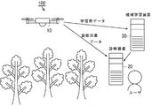
- FIG. 1 is a schematic configuration diagram of a diseased tree diagnosis system 100 according to the present embodiment.
- the diseased tree diagnosis system 100 includes a flying object 10, a diagnostic device 20, and a machine learning device 30.
- the diseased tree diagnosis system 100 takes an image of the tree to be diagnosed from the sky by the flying object 10, and uses a diagnostic model (neural network) created by deep learning to obtain the diseased tree from the image of the tree to be diagnosed. Diagnose.
- the diseased tree diagnosis system 100 of the present embodiment accurately grasps the characteristics of the disease appearing in the leaf group and diagnoses the diseased tree with high accuracy by performing the diagnosis based on the state of the leaf group photographed from above. I am trying to be able to do it.
- Hevea brasiliensis root rot is a disease caused by infection of the roots of Hevea brasiliensis root rot (Rigidoporus microporus), which is a type of filamentous fungus. As the disease progresses, the roots rot and the trees die. In addition, as the disease progresses, pathogens infect the roots of surrounding healthy trees and cause the disease, so it is desirable to detect the disease at an early stage and deal with it. However, lesions in the early stages of illness occur mainly in the underground roots, with slight changes in the above-ground part. For example, the leaves turn yellow when the roots cannot absorb enough water.
- the diseased tree diagnosis system 100 of the present embodiment diagnoses the disease based on the image of the leaf group. This makes it possible to make an accurate diagnosis based not only on the color of the leaves but also on the way the leaves are attached, particularly the density of the leaves and the angle of the leaves with respect to the branches. In addition, by using an image taken from above the tree, the leaves shown in this image are in a position where they can be seen from the sky, and those that have turned yellow due to poor sunlight can be excluded, so that the diagnosis can be made accurately.
- FIG. 2 is a configuration diagram of the flying object 10.
- the flying object 10 is a small unmanned aerial vehicle (drone) including a drive unit 11, a control unit 12, a photographing device 13, and a position information acquisition unit 14.
- the drive unit 11 obtains buoyancy by rotating the propeller by a motor or an internal combustion engine, and obtains thrust by tilting the rotation axis of the propeller with respect to the vertical axis.
- the configuration of the drive unit is not limited to this, and other configurations may be used. For example, it may be configured to have a balloon for obtaining buoyancy and a propeller for obtaining thrust.
- the control unit 12 receives an operation by the user, controls the drive unit 11 according to the operation, and controls the flight state of the flying object 10. In addition, the control unit 12 controls the photographing device 13 to control operations such as starting and stopping shooting and changing the shooting direction.
- the photographing device 13 forms an image of a tree as a diagnosis target on the light receiving surface of the image sensor 13B by the photographing lens 13A, converts the image into an electric signal by the image pickup element 13B, and acquires the data of the photographed image. Further, the photographing device 13 of the present embodiment records the data of the photographed image together with the photographing time.
- the position information acquisition unit 14 acquires position information by a satellite positioning system or the like, and records its own position (also referred to as a shooting position) when shooting with the shooting device 13 in association with the shot image. For example, position information (latitude, longitude, etc.) is acquired at a predetermined cycle and recorded as log data together with the acquisition time. As a result, by collating the shooting time of the shot image with the log data, it is possible to determine where the flying object 10 was located at the time of shooting.
- the log data may record attitude information indicating in which direction the flying object 10 is facing, together with the position information.
- the flying object 10 is not limited to a small unmanned aerial vehicle, but may be a manned airplane, a helicopter, an artificial satellite, or the like.
- FIG. 3 is a configuration diagram of the diagnostic device 20.
- the diagnostic apparatus 20 includes a target acquisition unit 21, a diagnostic unit 22, a diagnosis result output unit 23, and a position specifying unit 24.
- the target acquisition unit 21 acquires image data of the tree to be diagnosed from the flying object 10.
- the acquisition of the image data is connected to the flying object 10 via, for example, a communication cable or a communication network, and is received from the flying object 10 by communication.
- the flying object 10 may store the image data of the tree to be diagnosed in a storage medium such as a memory card, and the diagnostic device 20 may read the image data from the storage medium and acquire the image data.
- the diagnosis unit 22 receives the disease from the image of the tree using the image of the tree, the information indicating the range in which the leaf group is shown in the image, and the information indicating whether or not the disease has a characteristic of the disease in the range as teacher data.
- a diagnostic model in which machine learning is performed to diagnose a tree containing a diseased leaf group as a diseased tree, a tree including a diseased leaf group is diagnosed as a diseased tree. do.
- the diagnosis result output unit 23 outputs the result of the diagnosis by the diagnosis unit 22.
- the output of the result of this diagnosis is, for example, display on a display device, printing by a printer, storage on a storage medium, transmission to another device, or the like.
- the position specifying unit 24 identifies the position where the diseased tree exists based on the position in the image of the tree diagnosed as the diseased tree in the image to be diagnosed. For example, when the image of the diagnosis target is taken by an air vehicle flying over the tree, the position specifying unit determines the position of the air vehicle when the image of the diagnosis target is taken and the position of the air vehicle. Based on the position of the tree diagnosed as the diseased tree in the image, the position where the diseased tree exists is specified.
- FIG. 4 is a hardware configuration diagram of the diagnostic device 20.
- the diagnostic device 20 is a computer having a processor 222, a memory 223, an input / output IF (interface) 224, and a communication IF 225 connected to each other by a connection bus 221.
- the processor 222 processes the input information and outputs the processing result to control the entire apparatus.
- the processor 222 is also called a CPU (Central Processing Unit) or an MPU (Micro-processing unit).
- the processor 222 is not limited to a single processor, and may have a multiprocessor configuration. Further, it may be a multi-core configuration having a plurality of cores in a single chip connected by a single socket.
- Memory 223 includes a main storage device and an auxiliary storage device.
- the main storage device is used as a work area of the processor 222, a storage area for temporarily storing information processed by the processor 222, and a buffer area for communication data.
- the main storage device is a storage medium for the processor 222 to cache programs and data and expand a work area.
- the main storage device includes, for example, a RAM (RandomAccessMemory), a ROM (ReadOnlyMemory), and a flash memory.
- the auxiliary storage device is a storage medium that stores a program executed by the processor 222, data used for information processing, operation setting information, and the like.
- the auxiliary storage device is, for example, an HDD (Hard-disk Drive), an SSD (Solid State Drive), an EPROM (Erasable Programmable ROM), a flash memory, a USB memory, a memory card, or the like.
- the auxiliary storage device stores the image (photographed image) of the tree to be diagnosed received by the target acquisition unit 21 and the diagnosis result.
- the input / output IF224 is an interface for inputting / outputting data to / from a device connected to the diagnostic device 20.
- the input / output IF224 inputs / outputs data to / from a device such as a disk drive, an operation unit, or a display device that reads data from a storage medium such as a CD or DVD.
- the operation unit is an input unit such as a mouse, a keyboard, and a touch panel into which information for the diagnostic device 20 is input by an operator's operation.
- the display device is an output unit that displays and outputs information such as processing results to the operator.
- the communication IF25 is an interface (communication module) that communicates with other devices via the communication line N, and is also called a CCU (Communication Control Unit).
- a plurality of components of the diagnostic device 20 shown in FIG. 6 may be provided, or some components may not be provided.
- the diagnostic device 20 when the processor 222 executes the application program, the diagnostic device 20 is a processing unit such as a target acquisition unit 21, a diagnostic unit 22, a diagnosis result output unit 23, and a position specifying unit 24. Functions as. That is, the processor 222 can also be used as each processing unit depending on the software to be executed. However, some or all of the above processing units are dedicated LSIs (large scale integration) such as DSP (Digital Signal Processor), ASIC (Application Specific Integrated Circuit), FPGA (Field-Programmable Gate Array), logic circuits, and others. It may be formed by hardware such as a digital circuit of. Further, an analog circuit may be included in at least a part of each of the above processing units.
- LSIs large scale integration
- DSP Digital Signal Processor
- ASIC Application Specific Integrated Circuit
- FPGA Field-Programmable Gate Array
- logic circuits and others. It may be formed by hardware such as a digital circuit of. Further, an analog circuit may be included in at least a part of each
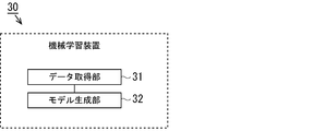
- FIG. 5 is a configuration diagram of the machine learning device 30. As shown in FIG. 5, the machine learning device 30 has a data acquisition unit 31 and a model generation unit 32.
- the data acquisition unit 31 acquires an image of the tree, information indicating the range in which the leaf group is shown in the image, and information indicating whether or not the disease has a characteristic in the range as teacher data.
- the model generation unit 32 generates a diagnostic model for diagnosing a tree including a diseased leaf group as a diseased tree from an image of the tree by machine learning using the teacher data.
- FIG. 6 is an explanatory diagram of processing using image data as teacher data.
- image 41 is an original image taken by the flying object 10. From this image 41, the area in which one tree is shown is extracted as the tree area 42. In the present embodiment, the tree area 42 is cut out at 800 ⁇ 800 pixels to 1500 ⁇ 1500 pixels.
- the leaf group is a group of a plurality of leaves, and includes, for example, 5 to 500 leaves.
- the number of leaves forming a leaf group may be appropriately determined according to the size (trunk diameter, tree height, etc.) and type of the tree, the age of the tree, the target detection accuracy, etc., and may be 10 to 300 or 10 to 50.
- the leaf group may include branches that support the leaves. Further, one leaf group may be a set of leaves derived from the same branch or a set of leaves within a predetermined distance from the tip of the branch.
- the predetermined distance is a value of 30 cm to 3 m, for example, 50 cm, 1 m, 2 m, and the like.
- the image of the leaf alone is not used as the teacher data, but the image of the leaf group (data of the tree region 42) is used as the teacher data.
- the teacher data of the present embodiment includes information such as the shape of a plurality of leaves, the distance between each leaf (leaf density), and the angle of the leaf with respect to the branch (how the leaves are attached), in addition to the color of the leaves. ..
- young leaves are soft and hang down as they move away from the branches, so the way the leaves are attached provides information on whether or not the leaves are young. Therefore, in the diagnostic model learned using the teacher data, if the leaves are dripping, it is judged to be healthy because the leaves are young, and if the leaves are not dripping, the leaves are judged to be healthy. It can be determined that there is a high possibility of yellowing.
- the diagnostic model learned using the teacher data can use the leaf density in the image of the leaf group as one of the information for diagnosing the disease.
- the image of the tree is learned, but the data used for the learning is not limited to the image of the tree.
- pre-learning is performed using an image set of general objects such as dogs and cats, and based on the pre-learned model, actual learning (transfer learning) is performed using images of trees to create a diagnostic model. good.
- transfer learning is performed using images of trees to create a diagnostic model. good.
- a diagnostic model with high detection accuracy can be generated even if the number of tree images is small, and the load of creating teacher data can be suppressed.
- the first height set to be a predetermined distance below the upper end of the tree and the first height set to be a predetermined distance below the first height are specified.
- a group of leaves existing between the second height set on the side may be specified.
- the first height is set at a distance of 50 cm to 5 m, such as 50 cm, 1 m, 3 m, etc., from the upper end of the tree.
- the second height is set to a distance of 50 cm to 10 m, such as 1 m, 3 m, 5 m, etc., from the first height.
- the first height may be set to a distance corresponding to 4% to 30% of the tree height, such as 4%, 6%, 20% of the tree height, from the upper end of the tree.
- the second height may be set to a distance corresponding to 6% to 50% of the tree height, such as 6%, 20%, 30% of the tree height, from the first height.
- the first height and the second height may be set according to the height (tree height) of the target tree.
- the tree height in this case is, for example, 10 m to 20 m.
- the target tree may be a tall tree of 5 m or more.
- the image of the tree to be diagnosed is subjected to at least one of rotation, movement, enlargement, reduction, inversion, color change, noise addition, blurring, high frequency component enhancement, and distortion, and after image processing.
- the image of is used as teacher data different from the image before image processing, and the number of teacher data may be increased. As a result, it is possible to generate a diagnostic model with high detection accuracy while suppressing the influence of brightness, image orientation, and the like.
- FIG. 7 is a hardware configuration diagram of the machine learning device 30.
- the machine learning device 30 is a computer having a processor 322, a memory 323, an input / output IF (interface) 324, and a communication IF 325 connected to each other by a connection bus 321.
- the processor 322 processes the input information and outputs the processing result to control the entire apparatus.
- the processor 322 is also called a CPU (Central Processing Unit) or an MPU (Micro-processing unit).
- the processor 322 is not limited to a single processor, and may have a multiprocessor configuration. Further, it may be a multi-core configuration having a plurality of cores in a single chip connected by a single socket.
- Memory 323 includes a main storage device and an auxiliary storage device.
- the main storage device is used as a work area of the processor 322, a storage area for temporarily storing information processed by the processor 322, and a buffer area for communication data.
- the main storage device is a storage medium for the processor 322 to cache programs and data and expand a work area.
- the main storage device includes, for example, a RAM (RandomAccessMemory), a ROM (ReadOnlyMemory), and a flash memory.
- the auxiliary storage device is a storage medium that stores a program executed by the processor 322, data used for information processing, operation setting information, and the like.
- the auxiliary storage device is, for example, an HDD (Hard-disk Drive), an SSD (Solid State Drive), an EPROM (Erasable Programmable ROM), a flash memory, a USB memory, a memory card, or the like.
- the input / output IF324 is an interface for inputting / outputting data to / from a device connected to the machine learning device 30.
- the input / output IF324 inputs / outputs data to / from a device such as a disk drive, an operation unit, or a display device that reads data from a storage medium such as a CD or DVD.
- the operation unit is an input unit such as a mouse, a keyboard, and a touch panel into which information for the machine learning device 30 is input by an operator's operation.
- the display device is an output unit that displays and outputs information such as processing results to the operator.
- the communication IF35 is an interface (communication module) that communicates with other devices via the communication line N, and is also called a CCU (Communication Control Unit).
- a plurality of components of the machine learning device 30 shown in FIG. 7 may be provided, or some components may not be provided.
- the processor 322 executes an application program, so that the machine learning device 30 functions as each processing unit such as a data acquisition unit 31 and a model generation unit 32. That is, the processor 322 can also be used as each processing unit depending on the software to be executed.
- some or all of the above processing units are dedicated LSIs (large scale integration) such as DSP (Digital Signal Processor), ASIC (Application Specific Integrated Circuit), FPGA (Field-Programmable Gate Array), logic circuits, and others. It may be formed by hardware such as a digital circuit of. Further, an analog circuit may be included in at least a part of each of the above processing units.
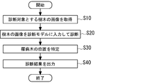
- FIG. 8 is a diagram showing a process in which the diagnostic device 20 diagnoses a diseased tree with respect to an image of a tree to be diagnosed.
- the diagnostic apparatus 20 executes the process of FIG. 8 when the start of diagnosis is instructed.
- step S10 the diagnostic device 20 acquires an image of the tree to be diagnosed.
- step S20 the diagnostic device 20 diagnoses the tree including the affected leaf group as a diseased tree by inputting the image of the tree acquired in step S10 into the diagnostic model generated by the machine learning device 30. , Diagnose a tree that does not contain the affected leaf group as a healthy tree.
- the diagnostic device 20 identifies the position where the diseased tree exists based on the position in the image of the tree diagnosed as the diseased tree in the image to be diagnosed.
- the diagnostic device 20 refers to the log data and is based on the position and attitude of the flying object 10 when the image to be diagnosed is taken, and the position of the tree diagnosed as the diseased tree in the image. , Identify the location of the diseased tree.
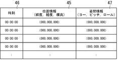
- FIG. 9 is a diagram showing an example of log data
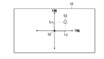
- FIG. 10 is an explanatory diagram of a process for identifying the position where the diseased tree exists based on the position in the image.
- the flying object 10 has the position information 45 of the flying object 10, the time information 46 indicating the time when the position information is acquired, and the attitude information 47 of the flying object 10 at the time.
- the position information 45 is, for example, information indicating a position using latitude and longitude (longitude / latitude) and altitude in the world geodetic system.
- the attitude information 47 is based on, for example, a state in which the flying object 10 is horizontal and faces a predetermined direction (for example, north), and the inclination from this reference state is indicated by rotation angles in the pitch direction, the roll direction, and the yaw direction. The value.
- the image 51 shown in FIG. 10 was taken by the photographing device 13, for example, the center of the image 51 is the origin 52, the X-axis passing through the origin 52 corresponds to the front-rear axis of the flying object 10, and the Y-axis is It corresponds to the left and right axes of the flying object 10.
- the flying object 10 arranges the photographing lens directly downward and the flying object 10 flies in a horizontal state, the object reflected in the center of the image 51 exists at the same latitude and longitude as the flying object 10.
- the object 53 is shown in the image 51 at a position separated from the origin 52 by a distance Lx in the X-axis direction and a distance Ly in the Y-axis direction.
- the distances corresponding to the distances Lx and Ly on the image 51 are obtained, for example, by the angle of view of the photographing lens and the altitude of the flying object 10 (height from the ground to the flying object).
- a position separated from the position of the flying object 10 by a distance corresponding to the distance Lx in the direction corresponding to the X-axis and a distance corresponding to the distance Lx in the direction corresponding to the X-axis is defined as the position where the object 53 exists. You can ask.
- the positional relationship between the position on the image and the position on the ground changes according to the tilt. Therefore, the position on the screen is changed according to the attitude information 47. Find the position on the ground corresponding to the position.
- step S40 the diagnostic device 20 outputs the position of the diseased tree obtained in step S30 as the result of the diagnosis.
- FIG. 11 is a diagram showing an example in which the positions of affected trees are plotted on a map.
- white “D”, “M”, and “L” indicate the diseased tree.
- “D” is severe
- “M” is moderate
- “L” is mildly affected tree.
- FIG. 12 is a diagram showing an SSD network structure. This technique is based on a feed-forward convolutional network, which produces a collection of fixed-length size bounding boxes, scores the existence of object class entities within those boxes, and finally.
- Non-maximum suppression is performed to generate a normal detection.
- the first layer of the network is based on the standard architecture used for image classification, which is the base network.
- the VGG-16 network was used as the base network, but it is not limited to this.
- Each added feature layer (or an existing feature layer in the base network) can generate a fixed set of detection predictions using a set of convolution filters. These are shown at the top of the SSD network structure in FIG.
- the basic element for predicting potential detection parameters is a small kernel of 3x3xp, which is relative to the category score, or the coordinates of the default box. Generate all shape offsets.
- the kernel produces an output value at each position of m ⁇ n to which it applies.
- the output value of the bounding box offset is measured against the position of the default box with respect to the position of each feature map.
- each feature map cell and a set of default bounding boxes are associated for multiple feature maps.
- the default boxes are convolved to fill the feature map tightly so that the position of each default box is fixed relative to its corresponding cell.
- c class scores and four offsets with respect to the shape of the original default box are calculated.
- the total number of filters applied around each position in the feature map is (c + 4) k, producing (c + 4) kmn outputs for the m ⁇ n feature map.
- the default box in this example applies to several feature maps with different resolutions. Using different default box shapes in some feature maps can efficiently discretize the output box shape. Also, in this example, the default box is matched with all correct boxes whose jaccard overlap is higher than the threshold (0.5). This simplifies the learning problem rather than having only one default box selected.
- ⁇ i x p ij ⁇ 1 can be obtained.
- the overall objective error function (loss function) is a weighted sum of the misalignment error (loc) and the classification error (conf) as in Equation A of FIG.
- N is the number of matching default boxes.
- the misalignment error is the Smooth L1 error between the parameters of the predicted box (l) and the correct answer box (g) (Equation B). Then, the offset is regressed with respect to the center (cx, xy) of the default bounding box (d) and its width (w) and height (h).
- the classification error is the softmax error for the certainty (c) of multiple classes (Equation C). In the next evaluation, the weight term ⁇ was set to 1 by cross-validation.
- FIG. 13 is a diagram showing a breakdown of a plurality of data sets.
- data of clones P2 to P3 and young to old trees were used.
- the data set (i) the data of the clone P2 and the block alone as the middle age of the tree were used, and in the data set (ii), the data of the clone P3 and the different ages of the tree from young to old were used.
- data set (iii) data of clones P2 to P4 and different clones of middle age were used.
- the dataset (iv) the entire data was used, and in the dataset (v), the data of the seriously affected trees were used.
- FIG. 14 is a diagram showing an example of the diagnosis result.
- H1 to H6 and D1 to D6 are tree regions extracted from the captured image by the diagnostic unit 22.
- the portion labeled with the rectangular frame is an image of the leaf group selected by the diagnostic unit 22.
- the diagnostic unit 22 of the present embodiment shows the selected leaf group having the characteristic of disease (hereinafter, also referred to as the diseased leaf group) in red, and in FIG. 14, the diseased leaf group is shown.
- the label is shaded with diagonal lines.
- the diagnostic unit 22 showed the frame and label of the selected leaf group of healthy ones having no characteristic of disease (hereinafter, also referred to as healthy leaf group) in blue.
- FIG. 14 FIG.
- the diagnostic unit 22 diagnoses the trees reflected in the tree regions H05, D1, D2, D4 to D6 having the diseased leaf group as the diseased tree, and the tree regions H01 to H4, H6, D3 having no diseased leaf group.
- the tree reflected in is diagnosed as a healthy tree.
- the trees in the tree areas H1 to H6 were healthy trees, and the trees in the tree areas D1 to D6 were diseased trees. .. That is, the tree region H5 mistakes a healthy tree for a diseased tree, the tree region D3 mistakes a diseased tree for a healthy tree, and the others are correct.
- TP is a case where the diagnosis result of the diagnosis unit 22 is illness and the confirmation result is illness.
- FP is a case where the diagnosis result of the diagnosis unit 22 is sick and the confirmation result is sound.
- FN is a case where the diagnosis result of the diagnosis unit 22 is sound and the confirmation result is illness.
- TN is a case where the diagnosis result of the diagnosis unit 22 is sound and the confirmation result is sound.
- the correct answer rate is the ratio at which the diagnosis result that the diagnosis unit 22 has determined to be "healthy” or “affected” and the actual confirmation result match, and is obtained from the following formula 1.
- Correct answer rate (TP + TN) / (TP + FP + TN + FN) ... Equation 1
- the precision rate is the ratio at which the diagnosis result of the diagnosis unit 22 as "affected” is actually “affected”, and is obtained from the following formula 2.
- Conformity rate TP / (TP + FP) ⁇ ⁇ ⁇ Equation 2
- Table 2 shows the results of evaluating the accuracy rate (Accuracy), precision rate (Precision), and recall rate (Recall) of the diagnosis results of the diagnosis unit 22 in comparison with the actual confirmation results.
- the morbidity rate is about 1%, so if all the trees are judged to be healthy, the correct answer rate will be 99%, but in this case, all the sick trees will be overlooked. Therefore, there is no point in increasing only the correct answer rate.
- the recall rate will be 100% and the diseased tree will not be overlooked, but the correct answer rate and the precision rate will be as low as 1%, and of course there is no point in diagnosing.
- the precision rate is low, when treating or cutting roots of a tree diagnosed as having a disease, it is confirmed that the root is actually healthy when the root is dug up, and the work such as digging up is wasted. Will often be. Therefore, it is desirable that the precision rate and the recall rate can be appropriately increased.
- the inventors of the present application repeatedly examined the SSD parameters shown in FIG. 12 to obtain the diagnostic result, and the loss function L (x, c, l, Focused on g).
- the inventors of this loss function L (x, c, l, g) under the condition that a plurality of trees are photographed from the sky and the characteristics of the leaf group are detected as in the present embodiment. It was found that the diagnostic accuracy can be improved by reducing the parameter ⁇ and increasing the weight of the classification error with respect to the misalignment error.
- Table 3 evaluates the diagnostic results when the parameter ⁇ is 0.5.
- the parameter ⁇ is not limited to 0.5, and may be, for example, in the range of 0.25 to 0.75.
- the diseased tree can be diagnosed with high accuracy.
- the accuracy is 20% or less. Therefore, the diagnostic device of the present embodiment greatly improves the diagnostic accuracy.
- the disease of Hevea brasiliensis has been described, but the diseased tree diagnosis system of this embodiment is not limited to Hevea brasiliensis, and if it is a disease characterized by disease in the leaf group, other diseases Can also be diagnosed.
Landscapes
- Life Sciences & Earth Sciences (AREA)
- Engineering & Computer Science (AREA)
- Biodiversity & Conservation Biology (AREA)
- Botany (AREA)
- Ecology (AREA)
- Forests & Forestry (AREA)
- Environmental Sciences (AREA)
- Computer Vision & Pattern Recognition (AREA)
- Physics & Mathematics (AREA)
- General Physics & Mathematics (AREA)
- Theoretical Computer Science (AREA)
- Image Analysis (AREA)
Applications Claiming Priority (2)
| Application Number | Priority Date | Filing Date | Title |
|---|---|---|---|
| JP2020045331A JP2021145557A (ja) | 2020-03-16 | 2020-03-16 | 罹病木診断システム、罹病木診断方法、及び罹病木診断プログラム |
| JP2020-045331 | 2020-03-16 |
Publications (1)
| Publication Number | Publication Date |
|---|---|
| WO2021187231A1 true WO2021187231A1 (ja) | 2021-09-23 |
Family
ID=77771220
Family Applications (1)
| Application Number | Title | Priority Date | Filing Date |
|---|---|---|---|
| PCT/JP2021/009241 Ceased WO2021187231A1 (ja) | 2020-03-16 | 2021-03-09 | 罹病木診断システム、罹病木診断方法、及び罹病木診断プログラム |
Country Status (2)
| Country | Link |
|---|---|
| JP (1) | JP2021145557A (https=) |
| WO (1) | WO2021187231A1 (https=) |
Cited By (2)
| Publication number | Priority date | Publication date | Assignee | Title |
|---|---|---|---|---|
| CN114141326A (zh) * | 2021-12-02 | 2022-03-04 | 杭州睿胜软件有限公司 | 用于追踪植物的康复情况的方法、装置和存储介质 |
| CN115953686A (zh) * | 2023-02-07 | 2023-04-11 | 开封市农林科学研究院 | 一种基于图像处理的花生虫害检测方法及系统 |
Families Citing this family (3)
| Publication number | Priority date | Publication date | Assignee | Title |
|---|---|---|---|---|
| JP7004962B1 (ja) | 2021-02-05 | 2022-01-21 | エムラインシステム株式会社 | 無人航空機の制御装置及び無人航空機システム |
| JP7627938B2 (ja) * | 2021-03-11 | 2025-02-07 | 国立研究開発法人農業・食品産業技術総合研究機構 | 情報処理装置、情報処理システム、情報処理方法、制御プログラム及び記録媒体 |
| JP7784661B2 (ja) * | 2022-01-19 | 2025-12-12 | 国立大学法人信州大学 | 森林被害木自動検出装置、森林被害木自動検出方法およびプログラム |
Citations (2)
| Publication number | Priority date | Publication date | Assignee | Title |
|---|---|---|---|---|
| JP2016168046A (ja) * | 2015-03-09 | 2016-09-23 | 学校法人法政大学 | 植物病診断システム、植物病診断方法、及びプログラム |
| JP2017163934A (ja) * | 2016-03-17 | 2017-09-21 | 国立大学法人信州大学 | 松くい虫の被害区分算定方法及び松くい虫の被害区分算定装置 |
-
2020
- 2020-03-16 JP JP2020045331A patent/JP2021145557A/ja active Pending
-
2021
- 2021-03-09 WO PCT/JP2021/009241 patent/WO2021187231A1/ja not_active Ceased
Patent Citations (2)
| Publication number | Priority date | Publication date | Assignee | Title |
|---|---|---|---|---|
| JP2016168046A (ja) * | 2015-03-09 | 2016-09-23 | 学校法人法政大学 | 植物病診断システム、植物病診断方法、及びプログラム |
| JP2017163934A (ja) * | 2016-03-17 | 2017-09-21 | 国立大学法人信州大学 | 松くい虫の被害区分算定方法及び松くい虫の被害区分算定装置 |
Non-Patent Citations (1)
| Title |
|---|
| ANONYMOUS: "Established disease diagnosis technology for natural rubber resource "Havea brasiliensis"", BRIDGESTONE CORPORATION, 10 July 2012 (2012-07-10), pages 1 - 5, XP055859056, Retrieved from the Internet <URL:https://www.bridgestone.co.jp/corporate/news/2012071001.html> [retrieved on 20211109] * |
Cited By (3)
| Publication number | Priority date | Publication date | Assignee | Title |
|---|---|---|---|---|
| CN114141326A (zh) * | 2021-12-02 | 2022-03-04 | 杭州睿胜软件有限公司 | 用于追踪植物的康复情况的方法、装置和存储介质 |
| CN115953686A (zh) * | 2023-02-07 | 2023-04-11 | 开封市农林科学研究院 | 一种基于图像处理的花生虫害检测方法及系统 |
| CN115953686B (zh) * | 2023-02-07 | 2023-07-28 | 开封市农林科学研究院 | 一种基于图像处理的花生虫害检测方法及系统 |
Also Published As
| Publication number | Publication date |
|---|---|
| JP2021145557A (ja) | 2021-09-27 |
Similar Documents
| Publication | Publication Date | Title |
|---|---|---|
| WO2021187231A1 (ja) | 罹病木診断システム、罹病木診断方法、及び罹病木診断プログラム | |
| CN111524137B (zh) | 基于图像识别的细胞识别计数方法、装置和计算机设备 | |
| EP3832524A1 (en) | System and method for determining damage on crops | |
| CN108921057B (zh) | 基于卷积神经网络的对虾形态测量方法、介质、终端设备及装置 | |
| CN117011688B (zh) | 一种水下结构病害的识别方法、系统及存储介质 | |
| CN110929944A (zh) | 基于高光谱图像与光谱特征相融合技术的小麦赤霉病病情严重度预测方法 | |
| KR102721266B1 (ko) | 딥러닝 기반 하수도 결함 감지 방법 및 그 장치 | |
| CN119399564B (zh) | 一种基于深度学习和嵌入式的玉米果穗损伤检测方法 | |
| CN114821346A (zh) | 一种基于嵌入式平台的雷达图像智能识别方法和系统 | |
| CN110570417B (zh) | 肺结节分类装置及图像处理设备 | |
| CN120852288B (zh) | 高分辨率风机叶片图像小缺陷检测方法及相关设备 | |
| CN113116377A (zh) | 超声成像导航方法、超声设备及存储介质 | |
| CN112529827A (zh) | 遥感图像融合模型的训练方法及装置 | |
| CN113269752A (zh) | 一种图像检测方法、装置终端设备及存储介质 | |
| CN109934804A (zh) | 基于卷积神经网络的阿尔茨海默病变区域的检测方法 | |
| CN120894459B (zh) | 一种基于大数据技术的医学图像伪影识别与剔除方法 | |
| CN111144449B (zh) | 图像处理方法、装置、存储介质及电子设备 | |
| CN120808193B (zh) | 基于深度学习的卫星遥感影像海水养殖识别方法及系统 | |
| CN116363530A (zh) | 高速公路路面病害的定位方法和装置 | |
| CN111476129A (zh) | 一种基于深度学习的土壤杂质检测方法 | |
| US12266098B2 (en) | Improving model performance by artificial blending of healthy tissue | |
| CN111339993A (zh) | 一种x射线图像金属检测方法和系统 | |
| CN111914766B (zh) | 一种城市管理业务游商行为检测方法 | |
| CN118366065B (zh) | 一种基于高度信息的无人机影像车辆检测方法及系统 | |
| CN116012283B (zh) | 一种全自动超声图像量测方法、设备及存储介质 |
Legal Events
| Date | Code | Title | Description |
|---|---|---|---|
| 121 | Ep: the epo has been informed by wipo that ep was designated in this application |
Ref document number: 21772137 Country of ref document: EP Kind code of ref document: A1 |
|
| NENP | Non-entry into the national phase |
Ref country code: DE |
|
| 122 | Ep: pct application non-entry in european phase |
Ref document number: 21772137 Country of ref document: EP Kind code of ref document: A1 |