WO2021186729A1 - Air conditioning system - Google Patents
Air conditioning system Download PDFInfo
- Publication number
- WO2021186729A1 WO2021186729A1 PCT/JP2020/012511 JP2020012511W WO2021186729A1 WO 2021186729 A1 WO2021186729 A1 WO 2021186729A1 JP 2020012511 W JP2020012511 W JP 2020012511W WO 2021186729 A1 WO2021186729 A1 WO 2021186729A1
- Authority
- WO
- WIPO (PCT)
- Prior art keywords
- air
- room
- temperature
- blower
- air conditioning
- Prior art date
Links
Images


Classifications
-
- F—MECHANICAL ENGINEERING; LIGHTING; HEATING; WEAPONS; BLASTING
- F24—HEATING; RANGES; VENTILATING
- F24F—AIR-CONDITIONING; AIR-HUMIDIFICATION; VENTILATION; USE OF AIR CURRENTS FOR SCREENING
- F24F11/00—Control or safety arrangements
- F24F11/70—Control systems characterised by their outputs; Constructional details thereof
- F24F11/72—Control systems characterised by their outputs; Constructional details thereof for controlling the supply of treated air, e.g. its pressure
- F24F11/74—Control systems characterised by their outputs; Constructional details thereof for controlling the supply of treated air, e.g. its pressure for controlling air flow rate or air velocity
- F24F11/76—Control systems characterised by their outputs; Constructional details thereof for controlling the supply of treated air, e.g. its pressure for controlling air flow rate or air velocity by means responsive to temperature, e.g. bimetal springs
-
- F—MECHANICAL ENGINEERING; LIGHTING; HEATING; WEAPONS; BLASTING
- F24—HEATING; RANGES; VENTILATING
- F24F—AIR-CONDITIONING; AIR-HUMIDIFICATION; VENTILATION; USE OF AIR CURRENTS FOR SCREENING
- F24F11/00—Control or safety arrangements
- F24F11/50—Control or safety arrangements characterised by user interfaces or communication
- F24F11/56—Remote control
- F24F11/58—Remote control using Internet communication
-
- F—MECHANICAL ENGINEERING; LIGHTING; HEATING; WEAPONS; BLASTING
- F24—HEATING; RANGES; VENTILATING
- F24F—AIR-CONDITIONING; AIR-HUMIDIFICATION; VENTILATION; USE OF AIR CURRENTS FOR SCREENING
- F24F11/00—Control or safety arrangements
- F24F11/70—Control systems characterised by their outputs; Constructional details thereof
- F24F11/72—Control systems characterised by their outputs; Constructional details thereof for controlling the supply of treated air, e.g. its pressure
- F24F11/74—Control systems characterised by their outputs; Constructional details thereof for controlling the supply of treated air, e.g. its pressure for controlling air flow rate or air velocity
- F24F11/77—Control systems characterised by their outputs; Constructional details thereof for controlling the supply of treated air, e.g. its pressure for controlling air flow rate or air velocity by controlling the speed of ventilators
-
- F—MECHANICAL ENGINEERING; LIGHTING; HEATING; WEAPONS; BLASTING
- F24—HEATING; RANGES; VENTILATING
- F24F—AIR-CONDITIONING; AIR-HUMIDIFICATION; VENTILATION; USE OF AIR CURRENTS FOR SCREENING
- F24F3/00—Air-conditioning systems in which conditioned primary air is supplied from one or more central stations to distributing units in the rooms or spaces where it may receive secondary treatment; Apparatus specially designed for such systems
- F24F3/044—Systems in which all treatment is given in the central station, i.e. all-air systems
- F24F3/048—Systems in which all treatment is given in the central station, i.e. all-air systems with temperature control at constant rate of air-flow
-
- F—MECHANICAL ENGINEERING; LIGHTING; HEATING; WEAPONS; BLASTING
- F24—HEATING; RANGES; VENTILATING
- F24F—AIR-CONDITIONING; AIR-HUMIDIFICATION; VENTILATION; USE OF AIR CURRENTS FOR SCREENING
- F24F2110/00—Control inputs relating to air properties
- F24F2110/10—Temperature
Definitions
- the present invention relates to an air conditioning system that air-conditions a plurality of rooms in a building with an air-conditioning unit and a ventilation unit.
- Houses are becoming more and more airtight and highly insulated in order to save energy and realize comfortable living.
- a whole building air conditioning system that blows air adjusted by an air conditioner to the entire house.
- a return section adjacent to a plurality of rooms is formed inside the building, and the room is provided with an intake part for blowing out air sent from a blower, and a return section is provided between the room and the return section.
- An exhaust unit that forms an exhaust airflow from the room to the return compartment is provided, and a plurality of blowers and at least one air conditioner are installed in the return compartment.
- the total air volume of the plurality of blowers is larger than the air conditioning air volume of the air conditioner.
- an air conditioner installed in the return compartment air-conditions a plurality of rooms at a uniform temperature with energy saving (see, for example, Patent Document 1).
- the ventilation means for ventilating the air in each room and the common space installed in the ceiling or under the floor of the house are installed in each room. It has an air conditioner indoor unit that cools and heats a plurality of rooms by using space as a chamber for supply air.
- other air-conditioning systems in the entire building include an air mixing box that mixes the air introduced from the outside air inlet and the air introduced from the inside air inlet, an air conditioner, and the air in the air mixing box in multiple rooms. It is equipped with a plurality of transport fans provided for each of a plurality of rooms for transport, a intake air temperature sensor, a transport air temperature sensor, and a system controller for controlling the air volume of the transport fan. Then, there is known one provided with a fan air volume control unit that controls the air volume of the transport fan based on the intake air temperature, the transport air temperature, and a predetermined threshold value (for example, Patent Document 4).
- the present invention solves such a conventional problem, is a system having a relatively simple structure, saves energy, keeps the whole house at a comfortable and uniform temperature, and according to personal preference, for each room.
- the purpose is to provide an air-conditioning system that can respond to changes in temperature and load changes due to sunlight and personnel in the room.
- the air conditioner system of the present invention forms a return section adjacent to a plurality of rooms in a building, and the room is provided with an intake unit that blows out air sent from a blower unit equipped with a DC motor.
- An exhaust section for forming an exhaust airflow from the room to the return section is provided between the room and the return section, and a plurality of the blower sections and at least one air conditioner section are provided in the return section.
- the total air volume of the plurality of air-conditioning units is larger than the air-conditioning air volume of the air-conditioning unit, and the air-blowing amount of the air-conditioning unit is adjusted by the air-conditioning load of the room.
- a plurality of blowers having a total air volume in which the conditioned air in which the exhaust air from the exhaust section of each room is air-conditioned by the air-conditioned section and the unair-conditioned exhaust air are larger than the air volume of the air-conditioned air.
- the conditioned air and exhaust air are surely mixed to become mixed conditioned air with a uniform temperature with a small difference from room temperature, and it is equipped with a highly efficient DC motor with a wide control range of rotation speed.
- the air-conditioning load in each room changes due to changes in the amount of solar radiation, the number of people in the room, etc.
- by adjusting the rotation speed of the DC motor of the blower section in a wider range energy-saving mixed air-conditioning air to each room
- another means has a temperature setting means for the room and a suction temperature detecting means for the blower portion, and determines the air conditioning load of the room based on the set temperature of the room and the suction temperature of the blower portion, and blows the air.
- the temperature can be set to the individual's preference for each room, and in the return compartment, the blower that blows air to each room takes in the mixed air-conditioned air that is a mixture of the exhaust air from each room and the air-conditioned air. Since it blows out from the part, the temperature of the exhaust air from each room and the room temperature of each room are estimated from the temperature of the intake air of the blower, and the air conditioning load of each room is determined by the set temperature of each room and the suction temperature of the blower part. , Adjust the air volume of the air blower.
- another means has a temperature setting means for the room and a room temperature detecting means for the room, determines the air conditioning load of the room based on the set temperature and the room temperature of the room, and determines the amount of air blown by the blower unit. It is something to adjust. As a result, the air conditioning load of each room can be determined more accurately from the room temperature of each room, and it is possible to set the temperature of each room more accurately, faster and more reliably, and create a comfortable space according to personal preference. An air conditioning system that can be obtained is obtained.
- another means has a communication means for connecting the temperature setting means in the room and the public line, and transmits data from the communication device connected to the public line through the communication means, and based on the data.
- the set temperature of the temperature setting means of the room is determined. This makes it possible to set the temperature of each room from communication devices inside and outside the building, making the room a comfortable space according to personal preference when there is no temperature setting means nearby even inside the building or while going out. It is possible to obtain a highly convenient air conditioning system.
- the other means has a temperature setting means of the return section, a room temperature detecting means of the return section, and a temperature setting means of the air conditioning unit, and air conditioning of the return section is performed according to the set temperature and room temperature of the return section.
- the load is determined and the set temperature of the air conditioning unit is adjusted.
- the air conditioning load in the return section can be quickly and accurately determined from the temperature and set temperature of the air in the return section sucked into the air conditioning section and the blower section, and the set temperature of the air conditioning section can be adjusted to adjust the set temperature of the air conditioning section. Since the capacity is adjusted and the suction temperature of the blower is also adjusted, even if the amount of air blown by the blower is adjusted, if the air conditioning load in the room cannot be met and the temperature cannot be adjusted to the personal preference, it will be faster and more reliable.
- an air-conditioning system that can set each room to a set temperature and create a comfortable space according to personal preference can be obtained. Further, even if the air-conditioning load of the room can be sufficiently coped with and the room can be set to the temperature of the individual's preference, an air-conditioning system capable of saving more energy and stabilizing the temperature of the individual's preference can be obtained.
- mixed air-conditioned air is sent to each room with a large amount of air by a plurality of air-conditioning units equipped with a DC motor capable of saving energy and controlling a wide range of rotation speeds, and the amount of air is increased according to the set temperature of each room. Since it is adjusted, it is possible to provide an air-conditioning system that can realize an individual's favorite comfortable temperature quickly and surely in response to the air-conditioning load.
- the suction temperature of the air-conditioning unit can be adjusted according to the air-conditioning load in the return section, which saves more energy, is faster, and is more reliable, and is comfortable for personal preference.
- An air conditioning system that can achieve temperature can be obtained.
- since it has a communication means and a communication device capable of communicating with the inside and outside of the building it is possible to realize a comfortable temperature of personal preference more quickly and more reliably from the communication device, and a highly convenient air conditioning system can be obtained.
- FIG. 1 is a first-floor plan view of a building showing the configuration of an air-conditioning system according to the first embodiment of the present invention
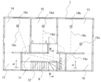
- FIG. 2 is a second-floor plan box of the same building.
- the entrance 2, the living room 3, the kitchen 4 are arranged on the first floor of the building 1 which is a highly airtight and highly insulated house, and the toilet 5, the bathroom 6, the washroom and the dressing room 7 and the like are provided.
- Living room 3 is provided with stairs 8 that go up to the second floor.
- the ceiling on the first floor of the building 1 is provided with outlet grills (intake units) 9a, 9b, 9c, and 9d that blow air into the room on the first floor.
- One ends of the first floor ventilation ducts 10a, 10b, 10c, and 10d are connected to the outlet grills 9a, 9b, 9c, and 9d, respectively.
- the other ends of the air ducts 10a, 10b, 10c, and 10d for the first floor are arranged on the second floor.
- the outlet grills 9a, 9b, 9c, and 9d may be provided on the floor instead of the ceiling.
- the blowout grills 9a, 9b, 9c, and 9d are provided on the floor, the first floor ventilation ducts 10a, 10b, 10c, and 10d are arranged under the floor.
- a staircase 12 composed of stairs 8 from the first floor and a corridor 11 is arranged on the second floor of the building 1.
- Room A13, room B14, and room C15 on the second floor of the building 1 are arranged adjacent to the staircase room 12.
- a storage room A16 is provided in the room A13.
- a storage room B17 is provided in the room B14.
- the ceiling 62 on the second floor of the building 1 is provided with outlet grills (intake units) 18a, 18b, 18c, and 18d that blow air into the room on the second floor.
- the outlet grills (intake units) 18a and 18b are provided on the ceiling 62 of the room A13 on the second floor.
- the outlet grill (intake unit) 18c is provided on the ceiling 62 of the room B14 on the second floor.
- the outlet grill (intake unit) 18d is provided on the ceiling 62 of the room C15 on the second floor.
- One ends of the second floor ventilation ducts 19a, 19b, 19c, 19d are connected to the outlet grills (intake portions) 18a, 18b, 18c, 18d, respectively.
- the outlet grills 18a, 18b, 18c, and 18d may be provided on the floor instead of the ceiling 62.
- the blowout grills 18a, 18b, 18c, 18d are provided on the floor, the second floor ventilation ducts 19a, 19b, 19c, 19d are arranged under the floor on the second floor.
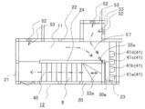
- FIG. 3 is an enlarged plan view of a staircase portion on the second floor of the building of the air conditioning system according to the present embodiment
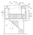
- FIG. 4 is a sectional view taken along the line AA of FIG. 2
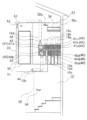
- FIG. 5 is a sectional view taken along the line BB of FIG.
- the staircase room 12 is a partition wall between the side wall 20 of the staircase 8 and the wall A21 where the staircase 8 is raised from the first floor, and the rooms A13, B14, and C15 on the second floor. It is surrounded by 22 and a wall B23 provided so as to face the wall A21. The distance between the wall A21 and the wall B23 is about 3.8 m, and the width of the stairs 8 and the corridor 11 is about 0.9 m.
- a handrail 24 is attached to the stairs 8 side of the corridor 11.
- the handrail 24 is composed of a horizontal rail 25 and a vertical rail 26.
- a slit 27 is formed between the vertical rail 26 and the vertical rail 26.
- a similar handrail 28 is attached to the space side of the first floor of the stairs 8.
- the air conditioner 30a is an outdoor unit in which a heat exchanger (not shown) and an air conditioner blower (not shown) that exchange heat between the refrigerant and air are housed in an integrated housing, and a compressor (not shown) is mounted. It is a wall-mounted indoor unit of a separate type air conditioner that is connected to the machine (not shown) by a refrigerant pipe (not shown) and a signal line (not shown).
- the air conditioner 30a has a function of setting the air volume of the indoor unit and the set temperature of the air conditioner between 16 ° C. and 30 ° C.
- the indoor unit has a suction air temperature sensor (not shown), and the inverter drive frequency of the compressor (not shown) is determined by the suction air temperature and the set temperature so that the suction air temperature approaches the set temperature quickly.
- the air conditioning capacity of the air conditioner 30a can be adjusted. Control.
- the upper surface 31 of the air conditioner 30a is provided with a suction port into which the suction airflow 32a is sucked.
- an outlet for blowing out the blown airflow 33a is provided in the lower part of the front surface of the air conditioner 30a.
- a vertical wind direction control plate 34 is provided at the air outlet. The vertical wind direction control plate 34 is set so that the blown airflow 33a is blown out in a substantially horizontal direction.
- the substantially horizontal direction includes a downward direction within 15 degrees from the horizontal direction.
- a horizontal wind direction control plate (not shown) is provided at the air outlet. The horizontal wind direction control plate is set so that the blown airflow 33a is blown toward the wall A21 substantially in parallel with the side wall 20.
- Blowers (blowers) 40a, 40b, 40c, 40d for the first floor and blowers (blowers) 41a, 41b, 41c, 41d for the second floor of the air conditioning system 29 are attached to the wall B23.
- the first-floor blowers 40a, 40b, 40c, 40d and the second-floor blowers 41a, 41b, 41c, 41d are arranged below the air conditioner 30a.
- Four first-floor blowers 40 are installed, and four second-floor blowers 41 are installed.
- One first-floor blower duct 10 is connected to one first-floor blower 40, and one second-floor blower is connected.
- One second floor air duct 19 is connected to 41.
- a DC motor (DC motor) 65 (see Fig. 7) and a sirocco fan that are more energy efficient than an AC motor and can control the rotation speed in a wider range in a stepless manner. 42 is provided.
- the rotation of the sirocco fan 42 sucks air from the staircase room 12, and the sucked air flows through the air duct 10 for the first floor and the air duct 19 for the second floor and blows out to each room in the building 1.
- a suction airflow 43 is generated.
- the sucked air flows in the first-floor airflow duct 10 and the second-floor airflow duct 19 as a blowout airflow 44.
- the first-floor blowers 40a, 40b, 40c, 40d and the second-floor blowers 41a, 41b, 41c, 41d are provided with a control device 80 (see FIG. 8) as air volume adjusting means.
- the control device 80 can change the rotation speed of the fan steplessly.
- the DC motor 65 is a brushless DC motor with high efficiency and high durability.
- an exhaust portion 52 is provided near the ceiling 62 higher than the air conditioner 30a of the partition wall 22 together with the lower gap 51 of the door 50 which is the entrance from the staircase room 12. ing.
- a second-floor exhaust airflow 53 is formed in the lower gap 51 and the exhaust portion 52.
- Each room on the first floor is provided with an opening that communicates with the staircase room 12. This opening corresponds to the discharge portion 55 to the staircase chamber 12, and the discharge airflow 56 on the first floor is formed in this opening. Therefore, the staircase room 12 is a return section where the air discharged from a plurality of rooms in the building 1 including the living room 3, the kitchen 4, the club room A13, the club room B14, and the club room C15 merges. That is, the staircase room 12, which is the return section, is adjacent to the living room 3, the kitchen 4, the club room A13, the club room B14, and the club room C15.
- the amount of air blown to each of the living room 3, the kitchen 4, the club room A13, the club room B14, and the club room C15 is determined from the volumes of the living room 3, the kitchen 4, the club room A13, the club room B14, and the club room C15. Then, the total air flow amount (hereinafter referred to as total air flow amount: Vh) is calculated by adding up the air flow amounts to the living room 3, the kitchen 4, the club room A13, the club room B14, and the club room C15. From the determined air volume, the air blowing capacity and the number of air blowers for each of the living room 3, the kitchen 4, the club room A13, the club room B14, and the club room C15 are selected.
- the blower duct constitutes a part of the blower. That is, the amount of air blown for selecting the blower is the amount of air blown from the blowing grill (intake unit) via the blowing duct.
- the amount of air required for air conditioning is at least 8 m 3 / h or more per 2.5 m 3 of the room, ideally about 20 m 3 / h, and the amount of air blown according to the size of the room and the air conditioning load such as sunlight. adjust.
- the air conditioning capacity of the air conditioner 30a is determined by calculating the air conditioning load for the building 1. That is, the air-conditioning load calculation includes heat transfer from walls, windows, ceilings, etc., radiant heat from sunlight passing through the window glass, heat and moisture generated from occupants, heat generated from lighting and machinery, intake outside air and gaps. Calculate the amount of heat and moisture from the wind as the air conditioning load (Yamada Haruten, "Frozen and Air Harmony", Japan, Yokendo Co., Ltd., March 20, 1975, p, 240-247). Then, with a margin in the load calculation result, the air conditioner 30a of the entire building 1 is selected from the air conditioners lined up by the capacity, and the entire building 1 is air-conditioned.
- the optimum air conditioning air volume of the air conditioner 30a (hereinafter referred to as the optimum air conditioning air volume: Vq) is determined from the total air volume: Vh calculated in the total air volume calculation step.
- Optimal air-conditioning air volume: Vq ensures that the air-conditioning air and exhaust air are mixed, and the mixed air-conditioning air with a uniform temperature with a small temperature difference from each room is blown by the blowers 40 and 41 with a large air volume.
- the total air volume 50% or less of Vh, at most less than 100%, and the air volume at which the air conditioner 30a can exert its capacity in response to the air conditioning load.
- the conditioned air volume is the air volume that passes through the heat exchanger (not shown) of the air conditioning unit 30a, and avoids pressure loss due to passing through the heat exchanger so that the mixed conditioned air can be blown out to each room with a large air volume. Therefore, in the case of an air conditioning unit that has an air passage that bypasses the heat exchanger, the air volume of the bypass air passage shall be excluded from the air conditioning air volume.
- the floor area of the building 1 is about 97.7 m2, the ceiling height is 2.5 m, and an air conditioner 30a having a cooling capacity equivalent to 4 kW is installed. 700m 3 / h is blown by a recirculation fan. For both the first-floor blower 40 and the second-floor blower 41 that blow air to each room, the air volume per unit is set to about 15 Om 3 / h. The total amount of air blown into the building 1 in the present embodiment: Vh is about 1200 m 3 / h, which is larger than the air-conditioned air volume of the air conditioner 30a.
- the total air volume: 58% of Vh is set as the air conditioning air volume (weak wind mode) that can be set by the air conditioner 30a.
- the total air volume Vh is 800 m 3 / h, which is larger than the air conditioning air volume 700 m 3 / h of the air conditioner 30a.
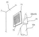
- FIG. 6 is a perspective view of the blower installation part
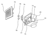
- FIG. 7 is a perspective exploded view of the blower
- FIG. 8 is an electric circuit diagram of the blower
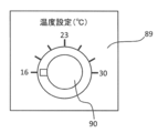
- FIG. 9 is a view showing an operation part of the temperature setting unit.
- a first-floor blower (blower) 40b is attached to the wall B23, and a first-floor blower duct 10b is connected to the first-floor blower 40b in the wall B23.
- the first-floor blower (blower) 40b has a box-shaped main body case 70 and a louver 71 detachably attached so as to cover the main body case 70 from the upper surface of the wall B23. Further, the louver 71 is provided with a vent 72, and air flows through the staircase 12 and the main body case 70 and the first floor ventilation duct 10b through the opening (not shown) of the wall B23. It is connected as a road.
- the louver 71 is detachably attached by the attachment portion 73 of the main body case 70 and the attachment spring 74.
- a DC motor 65 and a sirocco fan 42 are provided in the main body case 70, an electrical box 75 is provided on the side of the sirocco fan 42, and an optional mounting is provided between the main body case 70 and the louver 71.
- the base 76 is provided by being connected to the electrical box 75 by a lead wire 77.
- the sirocco fan 42 sucks air from the louver 71 by the rotation of the DC motor 65, passes through the air duct 10b, and blows it out from the blowout grill 9b to the living room 3.
- a plurality of optional units, a temperature sensor unit 78 and a temperature setting unit 79 are detachably attached to the option mounting base 76 from the front of the main body case 70 when the louver 71 is removed.
- the temperature sensor unit 78 is a unit that detects the temperature of the suction air of the blower 40b, and the temperature setting unit 79 sets the temperature of the living room 3 blown out from the blowout grill 9b through the blower duct 10b by the blower 40b. It is a unit.
- the temperature setting unit 79 functions as a unit for setting the temperature at a position near the blowout grills in the room. do.
- a control device 80 for controlling the operation of the DC motor 65 is provided in the electrical box 75.
- the control of the blower 40b will be described with reference to the electric circuit diagram of the blower of FIG. 8 and the operation unit of the temperature setting unit of FIG.
- the control device 80 is provided with a blower control unit 81 that controls the operation of the DC motor 65 of the blower 40b, and a power supply unit 82 that supplies power to the blower control unit 81.
- the option mounting base 76 includes two connectors 88a and 88b for connecting the temperature sensor unit 78 and the temperature setting unit 79 (temperature setting unit).
- These connectors 88a and 88b are connected to the power supply unit 82 and the ventilation control unit 81 of the control device 80 by the lead wire 77, and the power supply is supplied via the connectors 87a and 87b of the temperature sensor unit 78 and the temperature setting unit 79.
- Power is supplied from the unit 82 to the temperature sensor unit 78 and the temperature setting unit 79, and information is input from the temperature sensor unit 78 and the temperature setting unit 79 to the air blow control unit 81.
- the blast control unit 81 calculates the blast volume of the DC motor 65 using a preset algorithm (control logic) based on the information (detection information) input from the temperature sensor unit 78 and the temperature setting unit 79.
- the calculation unit 83 for determining the above is provided. The details of the algorithm used by the calculation unit 83 will be described later.
- the blast air volume information determined by the calculation unit 83 is input to the blast control unit 81, and the blast control unit 81 controls the rotation speed of the DC motor 65.
- the temperature sensor unit 78 includes a temperature sensor 85, a unit control unit 84a that controls the detection operation of the temperature sensor 85, and a connector 87a.
- the temperature sensor 85 has a function of detecting the temperature of the suction air sucked from the louver 71 of the blower 40b.
- a temperature sensor 85 that converts a change in temperature into a voltage is used, and is a resistance change type or a capacitance change type. A type of sensor such as is used.
- the unit control unit 84a outputs to the blow control unit 81 in order to determine the air volume to be operated by the DC motor 65 based on the detection signal from the temperature sensor 85. Further, the unit control unit 84a has a function of outputting identification information capable of identifying the output signal from the temperature sensor to the ventilation control unit 81.
- the temperature setting unit 79 includes a temperature setting unit 86, a unit control unit 84b that controls the detection operation of the temperature setting unit 86, and a connector 87b.
- the temperature setting unit 86 has an operation unit 89 for setting the temperature of the room (living room 3) blown by the blower 40b, and the operation unit 89 rotates to set the temperature to 16.
- It has a SW90 that can be set from ° C to 30 ° C.
- the SW90 is provided with a dial-type switch that can set the set temperature steplessly, but the SW90 is not limited to the dial-type switch, and various other configurations may be used as long as the switching setting is possible.
- the unit control unit 84b outputs to the blow control unit 81 in order to determine the air volume to be operated by the DC motor 65 based on the detection signal from the temperature setting unit 86. Further, the unit control unit 84b has a function of outputting identification information that can identify the output signal from the temperature setting unit to the blower control unit 81.
- the air conditioner unit is an air conditioner 30a in which a heat exchanger (not shown) and an air conditioner blower (not shown) are housed in an integrated housing, and the air conditioner unit is a blower 40a, 40b, 40c. , 40d, 41a, 41b, 41c, 41d, the return section is described as a staircase room 12 adjacent to a plurality of rooms, but the return section is like an air conditioning room (not shown) adjacent to a plurality of rooms.
- a relatively small room of about 1 tsubo surrounded by heat insulating walls on all sides may be provided with an air conditioner (air conditioner) and a blower (blower).
- the return section is a housing surrounded by sheet metal, etc.
- the housing is provided in a place adjacent to a plurality of rooms, only a heat exchanger is provided as an air conditioning unit in the housing, and a plurality of blowers are provided as a blower unit. Is provided, and the exhaust air is passed through the heat exchanger to be conditioned air by a plurality of blowers, and the exhaust air and the conditioned air that do not pass by bypassing the heat exchanger are mixed in the housing and used as mixed conditioned air. You may blow air into the room.
- the connectors 87a and 87b of the option units 78 and 79 and the connectors 88a and 88b of the option mounting base 76 have a common form so that they can be connected to each other. Therefore, any option unit selected from the plurality of option units can be connected to the connectors 88a and 88b of the option mounting base 76.
- a unit including a temperature sensor, a humidity sensor, an outside air temperature sensor, a carbon dioxide sensor, a solar radiation sensor, a human sensor, a temperature setting unit, a humidity setting unit, a sensor setting unit, and the like is used. It is also possible to disconnect the option unit once connected and connect another option unit.
- the case where the temperature sensor unit 78 and the temperature setting unit 79 selected from these option units are mounted on the unit mounting base 76 is taken as an example, but other option units are mounted. It may be the case.
- the case where two optional units are selectively mounted on the unit mounting base 76 has been described, but the case where only one is mounted or the case where three or more are mounted may be used.
- an optional mounting base that can be connected to the optional mounting base 76 so that the optional unit and the optional mounting base 76 can be provided in a place outside the main body case 70 of the blower 40b (for example, in the ceiling of a room, near a window, or in a duct).
- An optional unit extension unit (not shown) consisting of an extension lead wire, a connector and a cover may be provided and connected. Further, although the case where the air volume of the blower 40b determines the air volume steplessly is taken as an example, the air volume may be determined in multiple stages.
- the air conditioning blower (not shown) of the air conditioner 30a operates, and the temperature of the suction airflow 32a is measured by the suction air temperature sensor (not shown) of the air conditioner 30a. Detect and determine the air conditioning load from the suction air temperature and the set temperature, the inverter drive frequency of the compressor (not shown) of the outdoor unit (not shown), the electric expansion valve (not shown), and the outdoor blower (not shown).
- the air conditioning capacity of the air conditioner 30a is controlled by controlling (not shown) and adjusting the enthalpy and circulation amount of the refrigerant flowing into the heat exchanger (not shown).
- the conditioned air that has been heat-exchanged with the refrigerant in the heat exchanger becomes the blown airflow 33a of the air conditioner 30a, and blows out toward the wall A21 substantially horizontally and substantially parallel to the side wall 20. Further, when the blower 40 for the first floor and the blower 41 for the second floor are operated, the suction airflow 43 and the blowout airflow 44 of the blower are generated.
- the wind speed of the suction airflow 43 of the blower is about 0.4 m / s with respect to the wind speed of 3 to 5 m / S of the airflow 33a of the air conditioner 30a, and the suction airflow 43 of the blower is the wind speed of the airflow 33a of the air conditioner 30a. Slower. Further, since the blown airflow 33a of the air conditioner 30a is blown by the reflux fan, the airflow easily reaches a long distance, and it is difficult to be sucked into the suction airflow 43 of the blower generated by sucking the surrounding air by the operation of the sirocco fan 42. ..
- the direction of the blown airflow 33a during heating is the same as that during cooling so that the blown airflow 33a is blown in a substantially horizontal direction. It is desirable that the airflow is directed downward from the direction of the airflow 33a.
- the exhaust portion 52 may be provided anywhere as long as it is conductive to the staircase 12, but if it is provided near the ceiling 62 of the staircase 12 and close to the air conditioner 30a, the exhaust airflow 53 will be larger in the air conditioner 30a. Since the temperature of the suction airflow 32a is close to room temperature after being sucked in, the difference between the set temperature when operating the air conditioner 30a and the actual temperature in the building 1 is small and the operation is controlled.
- the air-conditioning circulation airflow 45 flows toward the exhaust airflow 53 and the suction airflow 43 until it reverses, and entrains and diffuses the surrounding air. Therefore, as the air-conditioning circulation airflow 45 flows, the temperature rises above the temperature of the air-conditioning airflow 33a during cooling and decreases below the temperature of the air-conditioning airflow 33a during heating.
- the air-conditioning circulation airflow 45 is mainly formed on the staircase 8 side of the staircase chamber 12, and the air-conditioning return airflow 57 is mainly formed on the corridor 11 side on the second floor of the staircase chamber 12.
- the airflow 33a of the air conditioner 30a, the exhaust airflow 56 on the first floor, and the exhaust airflow 53 on the second floor are generated in the staircase 12. It is mixed well and becomes mixed air-conditioned air. Then, the blowers 40 and 41 suck in the mixed air-conditioned air and blow it out to each room, so that the temperature difference between the temperature of the air-conditioned circulating airflow 45 and each room is further reduced. Air flows through the handrail 24 and the slit 27 of the handrail 28 to help this mixing. A part of the exhaust airflow 56 on the first floor joins the air-conditioned return airflow 57 from the boundary between the stairs 8 and the corridor 11. Further, in order to facilitate the merging of airflow from the first floor in the corridor 11, a ventilation slit may be provided in the corridor 11 to conduct the first floor and the second floor of the building 1 (not shown).
- the temperature difference between the temperature of the blown airflow 44 blown into each room and the room temperature of each room is smaller than the temperature difference between the temperature of the blown airflow 33a of the air conditioner 30a and each room.
- the person in the room is less likely to feel the stress due to the temperature difference between the airflow rate 44 and the room temperature, so that the comfort is improved.
- the air conditioner in which the rotation speed of the compressor is controlled by the inverter of the present embodiment, the air conditioner is operated so that the difference between the blowout temperature and the room temperature becomes small when the air conditioner air volume of the indoor unit is constant and the air conditioner load is small. do.
- the air conditioning air volume may be 100% or more of the total air volume: Vh.
- the air conditioner 30a, the first-floor blower 40, and the second-floor blower 41 may not all be installed on the wall B23. A part of the blower may be provided on the first floor of the staircase 12, or may be provided on the partition wall 22.
- Vh is larger than the air conditioning air volume, a part of the exhaust air returned from each room to the return section is sucked into the air conditioner 3Oa and the remaining exhaust air.
- the air is sufficiently mixed and air-conditioned in the return section with the blown air of the air conditioner 30a, becomes mixed air-conditioned air, and returns to each room. If the air volume is adjusted by the air volume adjusting means of the blowers 40 and 41, it is possible to respond to the fluctuation of the air conditioning load in the room for each of the blowers 40 and 41.
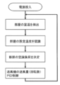
- the operation operation of the blower 40b will be described with reference to the blower amount adjusting flowchart 1 of the blower shown in FIG.
- the unit control units 84a and 84b detect the suction temperature of the blower 40b and set the room temperature. Is recognized.
- these pieces of information are input to the calculation unit 83, and the calculation unit 83 inputs the recognized set temperature as a target value and the detected suction temperature of the blower, and determines the air conditioning load of the room blown out by the blower.
- PID control is performed using the amount of air blown (number of rotations) of each blower as the operating amount.
- the building 1 is a highly airtight and highly insulated house, and since the wall facing the outside has good heat insulation and airtightness, the outside air load is small and the influence of heat entering from the adjacent room etc. Is the largest, and due to the large amount of air blown by the blowers 40 and 41, the temperature inside the building 1 tends to be uniform as a whole, and the exhaust air from each room is a staircase that is a direct return section from the exhaust section 52. 12 is entered and sucked into the blowers 40 and 41, and the air conditioning air volume is less than the total air flow volume.
- the room temperature of each room and the suction temperature of the blowers 40 and 41 have a temperature gradient. At least, the temperature of the exhaust air from each room and the room temperature of each room are estimated from the temperature of the intake air of the blowers 40 and 41, and simply, the temperature difference between the suction temperature of the blower and the set temperature of the room is multiplied by a constant. I'm looking for. However, in order to calculate the air conditioning load more accurately, an optional unit extension unit (not shown) is connected, and the optional mounting base 76 is placed in a place where the outdoor temperature can be detected, for example, outdoor air supply.
- an outside air temperature sensor (not shown) is provided as an optional unit, signal communication is performed with the blowers 40 and 41, the outside air temperature information is input to the calculation unit 83, and the temperature between the outside air temperature and the set temperature is set.
- the outside air load due to the difference may be added to the air conditioning load.
- a solar radiation sensor (not shown) is provided near the window of each room to perform signal communication with the blowers 40 and 41, input the solar radiation amount information from the window to the calculation unit 83, and use the solar radiation load as the air conditioning load.
- a human sensor (not shown) is provided on the ceiling of each room to perform signal communication with the blowers 40 and 41, and the occupant information is input to the calculation unit 83 to reduce the human load on the occupants. It may be added to the air conditioning load.
- the determined air flow amount (rotation speed) is input to the air blow control unit 81, and the DC motor 65 is rotated at the determined rotation speed.
- the rotation speed and the air flow amount are in a proportional relationship, and the rotation speed of the DC motor 65 is controlled so that the air flow amount is between a minimum of 100 m 3 / h and a maximum of 250 m 3 / h.
- the DC motor 65 has a wider control range from the minimum to the maximum rotation speed than the AC motor, and the rotation speed and the power consumption are in a proportional relationship, so that the amount of air blown (rotation speed) can be reduced.
- the difference in power consumption is larger than that of the AC motor, especially at the minimum air flow amount, and the power consumption is very small, less than 5 W.
- the suction temperature is 30 ° C
- the estimated room temperature is 14 ° C
- the set temperature is 20 ° C
- the heating and air conditioning load is large, so the air volume of the blowers 40 and 41 is set to 250 m 3 / h, which is the maximum air volume. Increase the temperature and bring the room temperature closer to the set temperature of 20 ° C.
- the heating and air conditioning load is small, so the air volume of the blowers 40 and 41 is set to 100 m 3 / h, which is the minimum air volume. Make it smaller and stabilize the room temperature at the set temperature of 16 ° C.
- the suction temperature is 23 ° C
- the estimated room temperature is 32 ° C
- the set temperature is 30 ° C
- the cooling and air conditioning load is small, so the air volume of the blowers 40 and 41 is reduced to 100 m 3 / h, which is the minimum air volume.
- the conditioned air in which the exhaust air from the exhaust section 52 of each room is conditioned by the air conditioner 30a and the unair-conditioned exhaust air are larger than the air volume of the conditioned air.
- the conditioned air and the exhaust air are surely mixed to become a mixed conditioned air having a uniform temperature with a small difference from the room temperature, and the control range of the number of rotations is controlled.
- the entire house is made uniform with energy saving.
- the rotation speed of the DC motors 65 of the blowers 40 and 41 can be adjusted in a wider range to save energy in each room.
- the temperature setting unit 89 can set the temperature to the individual's preference for each room, and the blowers 40 and 41 that blow air to each room in the staircase room 12 (return section) allow the exhaust air and air conditioning from each room. Since the mixed air-conditioned air mixed with air is blown out from the outlet grills 9a, 9b, 9c, 9d of each room, the temperature of the exhaust air from each room and the room temperature of each room can be determined from the temperature of the intake air of the blowers 40 and 41.
- the air conditioning load of each room is determined by the set temperature of each room and the suction temperature of the blowers 40 and 41, and the amount of air blown by the blowers 40 and 41 is adjusted. Can be brought closer to the set temperature to create a comfortable space according to personal preference.
- the minimum number of rotations of the DC motor 65 since the minimum air volume 100 m 3 / h of air blowing rate of the blower, the minimum total air volume of the plurality of fans even 800 m 3 / h, conditioned air of the air conditioner 30b 700 meters 3 / More than h, the conditioned air and the exhaust air are surely mixed to form a mixed conditioned air with a uniform temperature with a small temperature difference from the room temperature, which is sucked into each blower and blown to each room. Is air-conditioned to a more energy-saving and uniform temperature by operating the DC motors 65 of the blowers 40 and 41 at the minimum rotation speed.
- the entire building 1 can be used. If the mixed air-conditioned air is circulated, the effect on the temperature and comfort of each room is small if it is a short time such as one hour. Further, if there is an obstacle in the staircase room (return section) 12 and a short circuit occurs, the staircase room 12 may not be sufficiently mixed, or a temperature difference may occur depending on the position of the staircase room 12 due to sunlight from the window of the staircase room 12.
- a separate air volume setting SW may be connected to the blower so that the air volume of the blower can be set by the air volume setting SW according to personal preference, and the air volume setting SW (not shown) is automatically set.
- the operation may be controlled by the above flow.
- the room temperature is estimated from the suction temperature of the blower, and the air conditioning load of the room is determined by the suction temperature and the set temperature of the room.
- a humidity sensor (not shown)
- humidity setting unit (not shown) is added to detect the suction humidity of the blower, estimate the humidity of the room, recognize the set humidity of the room, and the suction temperature and suction humidity of the blower and the set temperature of the room. With the set humidity, the air conditioning load of the room may be determined, especially during summer cooling.
- FIG. 12 is a flow chart for adjusting the air volume of the blower
- FIG. 13 is a flow chart for adjusting the air volume of the blower 3
- FIG. 14 is a flow chart for adjusting the set temperature of the air conditioner. be.
- the air-conditioning system 100 shown in FIG. 11 is provided in the building 101 and has the same basic configuration as the air-conditioning system 29 provided in the building 1 of the first embodiment. The same number is assigned and some components are omitted. That is, in FIG. 11, the air conditioning system 100 and the building 101 have four rooms and air-condition the rooms, but the configuration such as the number of rooms and the number of blowers is not limited to that of the building 101.
- blowout grills (intake units) 9a and 9c for blowing air into the room on the first floor are provided.
- One ends of the first floor ventilation ducts 10a and 10c are connected to the outlet grills 9a and 9c, respectively.
- the rooms A13 and B14 on the second floor of the building 101 are arranged adjacent to the staircase room 12, and the ceilings of the rooms A13 and B14 have blowout grills (intake units) 18a and 18c for blowing air into the room on the second floor. It is provided. One ends of the second floor air ducts 19a and 19c are connected to the blowout grills 18a and 18c, respectively.
- the staircase room 12, which is a return section, is provided with an air conditioner (air conditioner) 30a, a blower for the first floor (blower) 40a, 40c, and a blower for the second floor (blower) 41a, 41c of the air conditioning system 100. .. Blowers 40a and 40c for the first floor and blowers 41a and 41c for the second floor are attached to the other ends of the blower ducts 10a and 10c for the first floor and the blower ducts 19a and 19c for the second floor.
- the living room 3, the kitchen 4, the room A13, and the room B14 are provided with remote controllers 110, 111, 112, and 113, which can operate the air conditioning system 100 in each room, respectively, and the staircase room 12, which is a return section, is provided with a remote controller.
- a centralized remote controller 115 electrically connected to 110, 111, 112, 113, an air conditioner 30a, and blowers 40a, 40c, 41a, 41c is provided, and each room can be set and operated in the staircase 12.
- the remote controllers 110, 111, 112, 113 and the centralized remote controller 115 have temperature sensors 120, 121, 122, 123, 125, and detect the room temperature of the living room 3, the kitchen 4, the room A13, the room B14, and the staircase room 12.
- the remote controllers 110, 111, 112, 113 and the centralized remote controller 115 have SW130, 131, 132, 133, 135 for setting the temperatures of the living room 3, the kitchen 4, the room A13, the room B14, and the staircase room 12.
- the temperature can be set from 16 ° C to 30 ° C by rotating.
- the remote controllers 110, 111, 112, 113 and the centralized remote controller 115 are connected by signal lines 140, 141, 142, 143, and the room temperature detected by the temperature sensors 120, 121, 122, 123 of the remote controller and SW 130, 131, 132, The information of the set temperature set in 133 is communicated.
- the centralized remote controller 115, the air conditioner 30a, and the blowers 40a, 40c, 41a, 41c are connected by signal lines 145, 146, 147, 148, 149, and the set temperature and air volume of the air conditioner 30a, the blowers 40a, 40c, The air volume of 41a and 41c is adjusted by communication.
- the display unit 150 can confirm the set temperature and room temperature of the remote controllers 110, 111, 112, 113 and the centralized remote controller 115 by communication, and the SW135 communicates the set temperatures of the remote controllers 110, 111, 112, 113. It is possible to change by.
- the air conditioner 30a sucks in the exhaust air. , Perform air-conditioning operation for cooling or heating, and blow out air-conditioned air. Then, the conditioned air is mixed with other exhaust air in the staircase 12 to become mixed conditioned air, which is sucked by the rotation of the DC motors 65 of the blowers 40a, 40c, 41a and 41c, and is sucked in by the rotation of the DC motor 65 for the first floor.
- the air is blown from the outlet grills 9a, 9c, 18a and 18c to the living room 3, the kitchen 4, the room A13 and the room B14, and the air is conditioned and becomes exhaust air.
- the staircase 12 which is the return section.
- the total air volume of the plurality of blowers is larger than the air conditioning air volume of the air conditioner 30a, the air conditioning air and the exhaust air are surely mixed, and the mixed air conditioning with a uniform temperature with a small temperature difference from the room temperature. Since it becomes air, is sucked into each blower, and is blown to each room, each room is energy-saving and air-conditioned to a uniform temperature.
- the operation operation of the blower will be described with reference to the blower amount adjusting flowchart 2 of the blower shown in FIG.
- the operation is started, and the temperature sensors 120, 121, 122, 123 provided on the remote controllers 110, 111, 112, 113 are used to adjust the room temperature of the living room 3, the kitchen 4, the room A13, and the room B14.
- the SW130, 131, 132, 133 of the remote controllers 110, 111, 112, 113 recognize the set temperatures of the living room 3, the kitchen 4, the room A13, and the room B14.
- the information on the room temperature and the set temperature of each room is communicated to the centralized remote controller 115 by the signal lines 140, 141, 142, and 143, and the control unit (not shown) of the centralized remote controller 115 is based on the information in each room.
- the air-conditioning load is determined, and PID control is performed using the amount of air blown (number of rotations) of each blower as the operating amount.
- the building 101 is a highly airtight and highly heat-insulated house, and the wall facing the outside has good heat insulation and airtightness. Is the largest, and it is simply calculated by multiplying the temperature difference between the room temperature and the set temperature by a constant.
- the room temperatures of the living room 3, the kitchen 4, the room A13, and the room B14 are detected by the temperature sensors 120, 121, 122, 123 provided on the remote controls 110, 111, 112, 113, and the SW130, 131.
- 132, 133 recognize the set temperature of each room, and the centralized remote control 115 determines the air conditioning load of each room and adjusts the amount of air blown by each blower.
- An optional unit extension unit (not shown) is connected to the optional mounting bases 76 of 40 and 41, and the optional mounting base 76 is connected to a place where the room temperature of each room can be detected, for example, near the door of each room or exhaust. It is provided near the unit 52, the temperature sensor unit 78 and the temperature setting unit 79 are connected to it, signal communication is performed with the blowers 40 and 41, the room temperature and the set temperature information is input to the calculation unit 83, and the room temperature and the setting of each room are set.
- the air conditioning load of each room may be obtained by multiplying the temperature difference of the temperature by a constant. In that case, the remote controllers 110, 111, 112, 113 and the centralized remote controller 115 become unnecessary.
- an outside air temperature sensor (not shown) is provided, outside air temperature information is input to the centralized remote controller 115, and the outside air load due to the temperature difference between the outside air temperature and the set temperature is air-conditioned.
- a solar radiation sensor (not shown) is installed in each room, and the solar radiation amount information from the window is input to the centralized remote controller 115 to add the solar radiation load to the air conditioning load, or a human sensor (figure) in each room. (Not shown) may be provided, and the occupant information may be input to the centralized remote controller 115 to add the human body load of the occupant to the air conditioning load.
- the determined air flow amount (rotation speed) is input to the air blow control unit (not shown) of each of the blowers 40 and 41 at the signal lines 146, 147, 148, and 149, and the DC motor 65 is rotated at the determined rotation speed. .. Since the air conditioning load of each room is determined by the room temperature and the set temperature of each room, the rotation speed of the DC motor 65 is controlled, and the amount of air blown by the blowers 40 and 41 is PID controlled, the difference between the room temperature and the set temperature is large. The larger the air conditioning load, the larger the amount of air blown by the blowers 40 and 41, and the room temperature of the room blown out by the blowers 40 and 41 approaches the set temperature earlier.
- the heating and air conditioning load is large, so the air volume of the blower 40 is increased to 250 m 3 / h, which is the maximum air volume, and the room temperature is set to the set temperature 20. Bring to °C quickly.
- the cooling air conditioning load is large, so the air volume of the blowers 40 and 41 is increased to 250 m 3 / h, which is the maximum air volume, and the room temperature is set to the set temperature 28. Bring to °C quickly.
- the cooling air conditioning load is small, so the air volume of the blowers 40 and 41 is reduced to 100 m 3 / h, which is the minimum air volume, and the room temperature is set to the set temperature 30. Stabilize at ° C. As a result, the air conditioning load of each room can be determined more accurately from the room temperature of each room, and energy saving, faster and more reliable, each room can be set to the set temperature and a comfortable space according to personal preference. can.
- the operation operation of the other blowers will be described with reference to the blower flow chart 3 of the blower shown in FIG.
- the room temperature is detected and the set temperature of the room is recognized.
- the air volume of the blowers 40 and 41 is set as the maximum air volume. If not, the PID control of the blower amount (rotation speed) of the blowers 40 and 41 is continued.
- the air volume of the blowers 40 and 41 is set to the maximum air volume of 250 m 3 / h. If the temperature of some rooms suddenly rises above the set temperature for some reason, such as an increase in the amount of solar radiation or the operation of another heater, the amount of heat is recovered and the other Since it is used for heating a room, it is possible to heat other rooms with energy saving by maximizing the amount of air blown by the blowers 40 and 41, returning a large amount of air in the room to the return section quickly, and blowing air into each room.
- PID control is performed based on the blower amount adjustment flowchart 2 of the blower shown in FIG.
- the air volume of the blowers 40 and 41 is set to the maximum air volume of 250 m 3 / h. If the temperature of some rooms suddenly drops below the set temperature for some reason, such as when another air conditioner is operated, the amount of heat is recovered and used for cooling the other rooms. By maximizing the amount of air blown by the blowers 40 and 41, returning a large amount of air in the room to the return section quickly and blowing air into each room, the other rooms can be cooled with energy saving. If this is not the case, PID control is performed based on the blower amount adjustment flowchart 2 of the blower shown in FIG.
- the operation operation of the air conditioner 30a will be described with reference to the set temperature control flowchart of the air conditioner shown in FIG.
- the temperature sensor 125 provided in the centralized remote controller 115 detects the room temperature of the staircase room 12 which is the return section.
- the SW135 of the centralized remote controller 115 recognizes the set temperature of the staircase room 12, which is the set return section.
- the control unit (not shown) of the centralized remote controller 115 determines the air conditioning load of the staircase room 12, which is the return compartment, and performs PID control using the set temperature of the air conditioner 30a as the operation amount.
- the building 101 is a highly airtight and highly heat-insulated house, and the wall facing the outside has good heat insulation and airtightness. Assuming that the influence is the largest, it is simply obtained by multiplying the temperature difference between the room temperature of the staircase chamber 12 and the set temperature by a constant. However, in order to calculate the air conditioning load more accurately, an outside air temperature sensor (not shown) is provided, signal communication is performed with the centralized remote controller 115, outside air temperature information is input, and the temperature difference between the outside air temperature and the set temperature is reached.
- the outside air load is added to the air conditioning load, or a solar radiation sensor (not shown) is provided in the staircase 12, signal communication is performed with the centralized remote controller 115, and the solar radiation amount information from the window is input to turn the solar radiation load into the air conditioning load. May be added.
- the determined set temperature is input to the air conditioning control unit (not shown) of the air conditioner 30a, and controls the compressor (not shown), the electric expansion valve (not shown), etc. together with the suction air temperature information to perform air conditioning. Control ability.
- the difference between the suction air temperature and the set temperature is proportional to the air conditioning capacity. For example, in winter, when the room temperature of the staircase 12 is 14 ° C. and the set temperature is 20 ° C., the heating / air conditioning load is large, so the set temperature of the air conditioner 30a is raised to 26 ° C. and the room temperature of the staircase 12 is set. Bring the temperature close to 20 ° C quickly.
- the cooling air conditioning load is large. Therefore, the set temperature of the air conditioner 30a is lowered to 20 ° C, and the room temperature of the staircase 12 is set to the set temperature 28. Bring to °C quickly.
- the suction air temperature of the air conditioner 30a also approaches the set temperature, and the power consumption of the compressor or the like of the air conditioner 30a is reduced. It is energy-saving and stable near the set temperature. For example, in winter, when the room temperature of the staircase 12 is 14 ° C.
- the heating / air conditioning load is small, so the set temperature of the air conditioner 30a is lowered to 22 ° C. and the room temperature of the staircase 12 is set. Stabilize at a temperature of 16 ° C. In summer, when the room temperature of the staircase 12 is 32 ° C and the set temperature is 30 ° C, the cooling air conditioning load is small, so the set temperature of the air conditioner 30a is raised to 22 ° C, and the room temperature of the staircase 12 is set to the set temperature 30. Stabilize at ° C.
- the air conditioning load of the staircase 12 is determined by the room temperature and the set temperature of the staircase 12 (return compartment), and the set temperature of the air conditioner 30a is PID controlled. Is controlled, and the room temperature of the staircase 12 (return section) approaches the set temperature quickly.
- the temperature of the staircase 12 (return compartment) is the average temperature of the mixed air-conditioned air that is the confluence of the exhaust air and the air-conditioned air after air-conditioning in each room. The temperature is higher and lower during heating, and depending on the set temperature of the air conditioner 30a, the air conditioning capacity is insufficient and the temperature does not approach the set temperature of the staircase 12 (return section).
- the room temperature of the staircase room 12 (return section) is brought closer to the set temperature more quickly and surely, and the room temperature of each room is also brought closer to the set temperature quickly and surely.
- the required air conditioning capacity of the air conditioner 30a also decreases, the number of revolutions of the compressor and the DC motor 65 decreases, the power consumption also decreases, the energy is saved, and the temperature becomes stable near the set temperature.
- the air conditioning load of the stair chamber 12 (return compartment) is quickly and accurately determined from the air temperature and the set temperature of the stair chamber 12 (return compartment) sucked into the air conditioner 30a and the blowers 40 and 41.
- each room can be set to the set temperature more quickly and more reliably to create a comfortable space according to the individual's preference. Further, even if the air conditioning load of the room can be sufficiently coped with and the temperature of the room can be adjusted to the personal preference, it is possible to save more energy and stabilize the temperature at the personal preference.
- timing (time) of the blower volume adjustment flow of the blowers 40 and 41 and the set temperature control flow of the air conditioner 30a the blower volume adjustment flow is frequently performed, and the set temperature control flow is occasionally performed. This is because if the set temperature of the air conditioner 30a is frequently adjusted, the amount of air blown to the entire house is reached, so that the power consumption is prevented from increasing. Examples of timing (time) are 1 to 4 below, but in any case, the actual optimum timing (time) differs depending on the air conditioning load of the building, the capacity of the air conditioner, the amount of air blown by the blower, etc.
- a structure is preferable in which the centralized remote controller 115, the remote controllers 110, 111, 112, 113 or the blowers 40 and 41 are provided with a timing SW, and the timing (time) can be changed by the timing SW.
- the air volume adjustment flow of the blowers 40 and 41 is performed every 5 minutes, and the set temperature adjustment flow of the air conditioner 30a is performed every hour. 2. It is set to 1 within 24 hours after the start-up of the air conditioner, and thereafter, the air volume adjustment flow of the blowers 40 and 41 is performed every 10 minutes, and the set temperature adjustment flow of the air conditioner 30a is performed every 2 hours. 3. 3. 3.
- the air volume adjustment flow of the blowers 40 and 41 is performed every 5 minutes, and when the time at which the difference between the room temperature and the set temperature of each room is equal to or higher than a certain threshold value continues for 1 hour or more, the set temperature adjustment flow of the air conditioner 30a is performed. It is started every 10 minutes until it falls below the threshold value. 4.
- the air conditioner is set to 3 within 24 hours after the start-up of the air conditioner, and after that, the air volume adjustment flow of the blowers 40 and 41 is performed every 10 minutes, and the time at a threshold value or more where there is a difference between the room temperature and the set temperature of each room is 1 hour. If the above is continued, the set temperature control flow of the air conditioner 30a is started, and thereafter, it is performed every 20 minutes until it becomes less than the threshold value.
- the set temperature and air volume of the air conditioner 30a and the air volume of the blowers 40a, 40c, 41a, 41c are controlled from the centralized remote controller 115, but the centralized remote controller 115 is not provided and the remote controllers 110, 111, It may be controlled directly from 112 and 113.
- the remote controllers 110, 111, 112, and 113 are not provided, and a temperature sensor for detecting the room temperature is separately provided in each room, the signal is communicated with the centralized remote controller 115, and the centralized remote controller 115 sets each room.
- the temperature may be set to control the air conditioner 30a and the blowers 40a, 40c, 41a, 41c.
- the communication between the centralized remote controller 115 and the remote controllers 110, 111, 112, 113 is on the signal lines 140, 141, 142, 143, and the communication between the centralized remote controller 115 and the blowers 40a, 40c, 41a, 41c is the signal line 146.
- the centralized remote controller 115 and the air conditioner 30a are communicated by a wired system with a signal line 145.
- a wireless method such as Bluetooth (registered trademark) or infrared may be used.
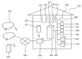
- FIG. 15 is a control system diagram of the air conditioning system according to the third embodiment of the present invention.
- the air conditioning system 160 shown in FIG. 15 has the same basic configuration as the air conditioning system 29 provided in the building 1 of the first embodiment and the air conditioning system 100 provided in the building 101, and is easy to explain. For the sake of conversion, the same components are given the same number, and some components are omitted.
- the air conditioner (air conditioner) 30a of the air conditioning system 160 In the return section (not shown) in the building 161, the air conditioner (air conditioner) 30a of the air conditioning system 160, the first floor blower (blower) 40a, 40c, and the second floor blower (blower) 41a, 41c are located.
- the kitchen (not shown) is provided with a range hood 162, and the bathroom is provided with ventilation equipment such as an air conditioner / drying ventilation fan 163.
- the operation can be controlled by inputting their operation information and outputting the operation information. It is connected to the HEMS (Home Energy Management System) remote control 164 by a communication line 165.
- HEMS Home Energy Management System
- Building 161 has four rooms: living room (not shown), kitchen (not shown), room A (not shown), and room B (not shown), and each room has blowers 40a and 40c. , 41a, 41c, through a duct (not shown) that blows out mixed air conditioning air, and a temperature sensor 175, 176, 177, 178 that detects the room temperature of each room. Further, the return compartment (not shown) has a temperature sensor 179 that detects the room temperature of the return compartment.
- the HEMS remote controller 164 is connected to the temperature sensors 175, 176, 177, 178, 179 and the communication line 165, and inputs the room temperature information of each room and the return section.
- the HEMS remote controller 164 includes temperature setting means (not shown) for each room and return compartment.
- the HEMS remote control 164 is provided with a communication device (communication means) 166, and the communication device 166 is connected to a public line 168 for information communication with the outside of the building, for example, a communication device (smartphone, mobile phone, personal computer, tablet, car navigation system). Etc.) Information communication such as input / output of operation information is possible with 169 and the server 170.
- a communication device smart phone, mobile phone, personal computer, tablet, car navigation system.
- Information communication such as input / output of operation information is possible with 169 and the server 170.
- it has an AI speaker (communication device) 167 that is wirelessly connected to the communication device 166 and has an AI assistant function by voice recognition in dialogue, and is connected to an external server 170 through a public line 168 to be connected to a HEMS remote controller. Information communication by voice such as input / output of operation information with 164 is possible.
- the temperature setting means (not shown) of the HEMS remote control 164 sets the temperature of the return compartment and each room, and operates the air conditioner 30a and the blowers 40a, 40c, 41a, 41c. Similar to 2, the air conditioning load of the return compartment and each room is determined by the room temperature information of the return compartment and each room from the temperature sensors 175, 176, 177, 178, 179 and the set temperature by the temperature setting means (not shown). Then, the set temperature of the air conditioner 30a is adjusted, the amount of air blown by the blowers 40a, 40c, 41a, and 41c is adjusted, and the room temperature of each room is quickly and surely brought close to the set temperature suitable for the individual's taste. In addition, it is possible to improve convenience and comfort without operating the HEMS remote controller 164 each time, such as changing the set temperature of each room and return compartment by voice with the AI speaker (communication device) 167. Is.
- the set temperature of each room and return section is changed to save energy when the person is absent, and when returning home, the room temperature is stabilized to suit the individual's taste. It is also possible to leave it.
- This makes it possible to set the temperature of each room from the communication device 169 inside and outside the building, and make the room a comfortable space according to personal preference when there is no temperature setting means nearby even inside the building or while going out. It is possible and the convenience is increased.
- the set temperature of each room and return section can be changed according to the power situation and weather in the area, and the power is stable as a area and energy saving as an individual. It can be controlled for comfortable driving.
- a human sensor (not shown) that detects the presence of people in each room is also connected, and the HEMS remote controller 164 is used to set the temperature of each room, the room temperature, the outside air temperature, the amount of solar radiation, and the number of people in each room.
- the air conditioning load of the blower 40a, 40c, 41a, 41c may be adjusted.
- an outside air temperature sensor (not shown) that detects the outside air temperature
- a solar radiation sensor not shown
- home appliances such as an IH stove and a lighting device may be connected to the HEMS remote controller 164 to enable operation.
- the HEMS remote control 164 is connected to a solar cell, a storage battery, a power conditioner, a power measuring device, etc., and each device can be more energy-saving and efficient according to the power consumption of each device, the amount of power generated by the solar cell, the amount of power stored in the storage battery, etc.
- the operation may be controlled.
- the communication method may be wired or wireless.
Abstract
Provided is an air conditioning system 29 in which: a return section is formed adjacent to a plurality of rooms 13, 14, 15 in a building; the rooms 13, 14, 15 are each provided with an intake unit 18a, 18b, 18c, 18d that blows air being fed from an air blowing unit 40a, 40b, 40c, 40d in which a DC motor 65 is mounted; between each room 13, 14, 15 and the return section, an exhaust unit 52 is provided which forms an exhaust air current directed from the room 13, 14, 15 towards the return section; multiple air blowing units 40a, 40b, 40c, 40d and at least one air conditioning unit 30a are disposed in the return section; the total airflow from the multiple air blowing units 40a, 40b, 40c, 40d is greater than the air conditioning airflow from the air conditioning unit 30a; and the airflow from the air blowing units 40a, 40b, 40c, 40d is adjusted in accordance with the air conditioning load of the rooms 13, 14, 15. As a result, it is possible, with a system having a relatively simple configuration, to change the temperature in each of the rooms 13, 14, 15 and address load changes due to sunlight and the like if necessary, while also saving energy and making an entire house a comfortable and uniform temperature.
Description
本発明は、建物内の複数の部屋を空調部と送風部で空調する空調システムに関する。
The present invention relates to an air conditioning system that air-conditions a plurality of rooms in a building with an air-conditioning unit and a ventilation unit.
住宅は省エネで快適な暮らし実現のため、ますます高気密化、高断熱化が進んでいる。高気密高断熱住宅に最適な空調として、空調機で調整した空気を家全体に送風する全館空調システムがある。
従来、この種の空調システムは、建物内部に、複数の部屋に隣接するリターン区画を形成し、部屋には、送風機から送られる空気を吹き出す吸気部を設け、部屋とリターン区画との間には、部屋からリターン区画に向けた排出気流を形成する排気部を設け、リターン区画に、複数台の送風機と少なくとも1台の空調機とを設置している。そして、空調機の空調風量よりも複数の送風機の合計送風量を多くしている。それにより、リターン区画に設置された空調機で複数の部屋を均一温度に省エネで空調するものが、知られている(例えば、特許文献1参照)。
また、複数の部屋と、廊下等の共用スペースとを有する住宅では、各部屋に設置された、当該各部屋の空気を通気する通気手段と、住宅の天井裏又は床下等に設置された、共用スペースを供給空気のチャンバーに用いて複数の部屋を冷・暖房するエアコン室内ユニットとを有している。そして、複数の通気手段の風量の総和と、エアコン室内ユニットの供給風量とを略等しく制御し、全館空調でありながらある程度の個別空調が可能となるものが知られている(例えば、特許文献2参照)。
また、他の全館空調システムは、熱源機と、分配装置と、複数の温度センサーと、制御装置と、を備えている。その制御装置は、複数の温度センサーそれぞれが計測した温度を複数の空調空間それぞれの現在温度として取得して、現在温度と複数の空調空間それぞれの目標温度との差を小さくするように熱源機及び分配装置を制御するものが知られている(例えば、特許文献3参照)。
また、他の全館空調システムは、外気導入口から導入された空気と内気導入口から導入された空気とを混合する空気混合ボックスと、空調機と、空気混合ボックス内の空気を複数の部屋に搬送する、複数の部屋毎に対応して設けられた複数の搬送ファンと、取込空気温度センサーと、搬送空気温度センサーと、搬送ファンの風量を制御するシステムコントローラと、を備えている。そして、取込空気温度と搬送空気温度と所定の閾値とに基づいて搬送ファンの送風量を制御するファン風量制御部を備えたものが知られている(例えば、特許文献4)。
さらに、複数のエリアを空調するVAVシステムでは、VAVユニットのダンパーを全開にしても、該当エリアの室内温度が規定の時間内に室内温度設定値に到達することができない場合に、他のエリアを最小風量とし、該当エリアの風量増を行う。それでも該当エリアの室内温度が室内温度設定値に到達していない場合に、給気温度設定値を変更するものが知られている(例えば、特許文献5)。 Houses are becoming more and more airtight and highly insulated in order to save energy and realize comfortable living. As the optimum air conditioning for a highly airtight and highly insulated house, there is a whole building air conditioning system that blows air adjusted by an air conditioner to the entire house.
Conventionally, in this type of air conditioning system, a return section adjacent to a plurality of rooms is formed inside the building, and the room is provided with an intake part for blowing out air sent from a blower, and a return section is provided between the room and the return section. , An exhaust unit that forms an exhaust airflow from the room to the return compartment is provided, and a plurality of blowers and at least one air conditioner are installed in the return compartment. Then, the total air volume of the plurality of blowers is larger than the air conditioning air volume of the air conditioner. As a result, it is known that an air conditioner installed in the return compartment air-conditions a plurality of rooms at a uniform temperature with energy saving (see, for example, Patent Document 1).
Further, in a house having a plurality of rooms and a common space such as a corridor, the ventilation means for ventilating the air in each room and the common space installed in the ceiling or under the floor of the house are installed in each room. It has an air conditioner indoor unit that cools and heats a plurality of rooms by using space as a chamber for supply air. Then, it is known that the total air volume of a plurality of ventilation means and the air volume supplied by the air conditioner indoor unit are controlled substantially equally, and individual air conditioning can be performed to some extent even though the entire building is air-conditioned (for example, Patent Document 2). reference).
In addition, other whole building air conditioning systems include a heat source unit, a distribution device, a plurality of temperature sensors, and a control device. The control device acquires the temperature measured by each of the plurality of temperature sensors as the current temperature of each of the plurality of air conditioning spaces, and reduces the difference between the current temperature and the target temperature of each of the plurality of air conditioning spaces. Those that control the distribution device are known (see, for example, Patent Document 3).
In addition, other air-conditioning systems in the entire building include an air mixing box that mixes the air introduced from the outside air inlet and the air introduced from the inside air inlet, an air conditioner, and the air in the air mixing box in multiple rooms. It is equipped with a plurality of transport fans provided for each of a plurality of rooms for transport, a intake air temperature sensor, a transport air temperature sensor, and a system controller for controlling the air volume of the transport fan. Then, there is known one provided with a fan air volume control unit that controls the air volume of the transport fan based on the intake air temperature, the transport air temperature, and a predetermined threshold value (for example, Patent Document 4).
Furthermore, in a VAV system that air-conditions multiple areas, even if the damper of the VAV unit is fully opened, if the indoor temperature of the relevant area cannot reach the indoor temperature set value within the specified time, the other areas may be opened. Set the minimum air volume and increase the air volume in the relevant area. Even so, it is known that the supply air temperature set value is changed when the indoor temperature of the corresponding area does not reach the indoor temperature set value (for example, Patent Document 5).
特許文献1に記載の空調システムでは、室温との差が小さい空調空気を複数の送風機により、各部屋へ大風量で送風することにより、比較的シンプルな構成のシステムで、省エネで家全体を均一な温度にできるが、個人の好みにより、部屋毎に温度を変更することや、日射量や在室人員の変化などによる負荷変化に対応する手段が想定されていないという問題があった。
また、特許文献2に記載の空調システムでは、各部屋の室温と設定温度の差により通気手段の風量を変えるものであるが、複数の通気手段の風量の総和と、エアコン室内ユニットの供給風量とを略等しく制御するため、エアコンから吹出された室温との差が大きい空調空気が、共用スペースを通って各部屋に移動する間に、伝熱により、各部屋に送風される空調空気の温度がそれぞれ変化し、各部屋を均一な温度にするのが困難という問題もあった。
また、特許文献3に記載の全館空調システムでは、現在温度と複数の空調空間それぞれの目標温度との差を小さくするように熱源機及び分配装置を制御するものであるが、目標温度と熱源機から吹出された空気の現在温度との差が大きい空調空気が、分配装置を通ることにより、風量が減らされ、各空調空間に移動する間に、伝熱により、各空調空間に送風される空調空気の温度がそれぞれ変化し、同様に、各空調空間を均一な温度にするのが困難であった。
また、特許文献4に記載の全館空調システムでは、空気混合ボックス内に取り込む空気の温度と、搬送ファンで搬送する空気の温度差により、搬送ファンの送風量を制御するものであるから、部屋毎に温度を変更することや、日射などによる負荷変化に対応できないという問題があった。
さらに、特許文献5に記載のVAVシステムでは、各エリアの室内温度を室内温度設定値に近づけることは可能であるが、室温との差が大きい空調空気の風量が、ダンパーの圧力損失によって減少し、全体的な風量を増やさないで給気温度設定値を変更することにより、さらに空調空気と室温との差を大きくするので、各エリアの室温を省エネで均一に維持することは困難であった。 In the air-conditioning system described inPatent Document 1, air-conditioned air having a small difference from the room temperature is blown to each room with a large amount of air by a plurality of blowers. However, there is a problem that the temperature can be changed for each room according to individual preference, and the means for responding to the load change due to the change in the amount of solar radiation and the number of people in the room is not assumed.
Further, in the air conditioning system described in Patent Document 2, the air volume of the ventilation means is changed depending on the difference between the room temperature and the set temperature of each room. The temperature of the air-conditioning air blown to each room by heat transfer while the air-conditioning air, which has a large difference from the room temperature blown out from the air conditioner, moves to each room through the common space. There was also a problem that it was difficult to make each room a uniform temperature because each room changed.
Further, in the whole building air conditioning system described inPatent Document 3, the heat source machine and the distribution device are controlled so as to reduce the difference between the current temperature and the target temperature of each of the plurality of air conditioning spaces. Air conditioning that has a large difference from the current temperature of the air blown out from is reduced in air volume by passing through the distributor, and while moving to each air conditioning space, air is blown to each air conditioning space by heat transfer. The temperature of the air changed, and it was also difficult to make each air-conditioned space uniform.
Further, in the whole building air conditioning system described inPatent Document 4, since the air volume of the transport fan is controlled by the temperature difference between the temperature of the air taken into the air mixing box and the temperature of the air transported by the transport fan, the amount of air blown by the transport fan is controlled for each room. There was a problem that the temperature could not be changed and the load could not be changed due to sunlight.
Further, in the VAV system described inPatent Document 5, it is possible to bring the indoor temperature of each area close to the indoor temperature set value, but the air volume of the conditioned air having a large difference from the room temperature is reduced by the pressure loss of the damper. By changing the supply air temperature setting value without increasing the overall air volume, the difference between the conditioned air and the room temperature is further increased, so it was difficult to maintain the room temperature in each area uniformly with energy saving. ..
また、特許文献2に記載の空調システムでは、各部屋の室温と設定温度の差により通気手段の風量を変えるものであるが、複数の通気手段の風量の総和と、エアコン室内ユニットの供給風量とを略等しく制御するため、エアコンから吹出された室温との差が大きい空調空気が、共用スペースを通って各部屋に移動する間に、伝熱により、各部屋に送風される空調空気の温度がそれぞれ変化し、各部屋を均一な温度にするのが困難という問題もあった。
また、特許文献3に記載の全館空調システムでは、現在温度と複数の空調空間それぞれの目標温度との差を小さくするように熱源機及び分配装置を制御するものであるが、目標温度と熱源機から吹出された空気の現在温度との差が大きい空調空気が、分配装置を通ることにより、風量が減らされ、各空調空間に移動する間に、伝熱により、各空調空間に送風される空調空気の温度がそれぞれ変化し、同様に、各空調空間を均一な温度にするのが困難であった。
また、特許文献4に記載の全館空調システムでは、空気混合ボックス内に取り込む空気の温度と、搬送ファンで搬送する空気の温度差により、搬送ファンの送風量を制御するものであるから、部屋毎に温度を変更することや、日射などによる負荷変化に対応できないという問題があった。
さらに、特許文献5に記載のVAVシステムでは、各エリアの室内温度を室内温度設定値に近づけることは可能であるが、室温との差が大きい空調空気の風量が、ダンパーの圧力損失によって減少し、全体的な風量を増やさないで給気温度設定値を変更することにより、さらに空調空気と室温との差を大きくするので、各エリアの室温を省エネで均一に維持することは困難であった。 In the air-conditioning system described in
Further, in the air conditioning system described in Patent Document 2, the air volume of the ventilation means is changed depending on the difference between the room temperature and the set temperature of each room. The temperature of the air-conditioning air blown to each room by heat transfer while the air-conditioning air, which has a large difference from the room temperature blown out from the air conditioner, moves to each room through the common space. There was also a problem that it was difficult to make each room a uniform temperature because each room changed.
Further, in the whole building air conditioning system described in
Further, in the whole building air conditioning system described in
Further, in the VAV system described in
本発明は、このような従来の課題を解決するものであり、比較的シンプルな構成のシステムで、省エネで、家全体を快適な均一な温度にしながら、個人の好みに応じて、部屋毎に温度を変更することや、日射や在室人員などによる負荷変化に対応できる空調システムを提供することを目的としている。
The present invention solves such a conventional problem, is a system having a relatively simple structure, saves energy, keeps the whole house at a comfortable and uniform temperature, and according to personal preference, for each room. The purpose is to provide an air-conditioning system that can respond to changes in temperature and load changes due to sunlight and personnel in the room.
本発明の空調システムは上記目的を達成するために、建物に、複数の部屋に隣接するリターン区画を形成し、前記部屋には、DCモーターを搭載した送風部から送られる空気を吹き出す吸気部を設け、前記部屋と前記リターン区画との間には、前記部屋から前記リターン区画に向けた排出気流を形成する排気部を設け、前記リターン区画に、複数の前記送風部と少なくとも1台の空調部とを設置し、複数の前記送風部の合計送風量が前記空調部の空調風量よりも多く、前記部屋の空調負荷によって、前記送風部の送風量を調節するものである。
この手段により、リターン区画にて、各部屋の排気部からの排出空気を空調部にて空調した空調空気と空調されていない排出空気が、その空調空気の風量より多い合計送風量の複数の送風機に吸引されることにより、空調空気と排出空気を確実に混合し、室温との差が小さい均一な温度の混合空調空気となり、それを回転数の制御範囲が広く、高効率なDCモーターを搭載した複数の送風部で吸込み、各部屋の吸気部より送風することにより、省エネで家全体を均一な温度にできる。
さらに、日射量、在室人員等の変化により、部屋毎の空調負荷が変化した場合、送風部のDCモーターの回転数をより広い範囲で調節することにより、省エネで各部屋への混合空調空気の送風量をより広い範囲で調節し、各部屋の温度への日射や在室人員等の影響を少なくし、快適にすることができる空調システムが得られる。
また他の手段は、前記部屋の温度設定手段と前記送風部の吸込み温度検知手段を有し、前記部屋の設定温度と前記送風部の吸込み温度によって、前記部屋の空調負荷を決定し、前記送風部の前記送風量を調節するとしたものである。
これにより、部屋毎に個人の好みの温度に設定可能で、リターン区画にて、各部屋に送風する送風機により、各部屋からの排出空気と空調空気を混合した混合空調空気を、各部屋の吸気部から吹出すので、送風機の吸込み空気の温度から各部屋からの排出空気の温度と各部屋の室温を推定し、各部屋の設定温度と送風部の吸込み温度により各部屋の空調負荷を決定し、送風部の送風量を調節する。そのため、省エネで、より早く、より確実に、各部屋を設定温度に近づけ、個人の好みに応じた快適空間にすることができる空調システムが得られる。
また、他の手段は、前記部屋の温度設定手段と前記部屋の室温検知手段を有し、前記部屋の設定温度と室温によって、前記部屋の空調負荷を決定し、前記送風部の前記送風量を調節するものである。
これにより、各部屋の室温から、各部屋の空調負荷をより正確に判定でき、省エネで、より早く、より確実に、各部屋を設定温度にし、個人の好みに応じた快適空間にすることができる空調システムが得られる。
また、他の手段は、前記部屋の前記温度設定手段と公衆回線を繋ぐ通信手段を有し、前記公衆回線に繋がる通信装置から、前記通信手段を通して、データを送信して、前記データに基づいて、前記部屋の前記温度設定手段の設定温度を決定するものである。
これにより、建物の内部及び外部の通信装置から各部屋の温度設定が可能となり、建物内でも近くに温度設定手段がない場合や、外出中に、部屋を個人の好みに応じた快適空間にすることができ、利便性の高い空調システムが得られる。
また、他の手段は、前記リターン区画の温度設定手段、前記リターン区画の室温検知手段及び、前記空調部の温度設定手段を有し、前記リターン区画の設定温度と室温によって、前記リターン区画の空調負荷を決定し、前記空調部の設定温度を調節するものである。
これにより、空調部と送風部に吸い込まれるリターン区画の空気の温度と設定温度から、リターン区画の空調負荷を、早く、正確に判定し、空調部の設定温度を調節することにより、空調部の能力が調節され、送風部の吸込み温度も調節されるので、送風部の送風量を調節しても、部屋の空調負荷に対応できず、個人の好みの温度にできない場合、より早く、より確実に、各部屋を設定温度にし、個人の好みに応じた快適空間にすることができる空調システムが得られる。又、部屋の空調負荷に十分対応でき、部屋を個人の好みの温度にできる場合でも、より省エネで、個人の好みの温度に安定させることができる空調システムが得られる。 In order to achieve the above object, the air conditioner system of the present invention forms a return section adjacent to a plurality of rooms in a building, and the room is provided with an intake unit that blows out air sent from a blower unit equipped with a DC motor. An exhaust section for forming an exhaust airflow from the room to the return section is provided between the room and the return section, and a plurality of the blower sections and at least one air conditioner section are provided in the return section. The total air volume of the plurality of air-conditioning units is larger than the air-conditioning air volume of the air-conditioning unit, and the air-blowing amount of the air-conditioning unit is adjusted by the air-conditioning load of the room.
By this means, in the return section, a plurality of blowers having a total air volume in which the conditioned air in which the exhaust air from the exhaust section of each room is air-conditioned by the air-conditioned section and the unair-conditioned exhaust air are larger than the air volume of the air-conditioned air. By being sucked into, the conditioned air and exhaust air are surely mixed to become mixed conditioned air with a uniform temperature with a small difference from room temperature, and it is equipped with a highly efficient DC motor with a wide control range of rotation speed. By sucking in air from multiple air-conditioning units and blowing air from the air-conditioning units in each room, it is possible to save energy and keep the temperature of the entire house uniform.
Furthermore, when the air-conditioning load in each room changes due to changes in the amount of solar radiation, the number of people in the room, etc., by adjusting the rotation speed of the DC motor of the blower section in a wider range, energy-saving mixed air-conditioning air to each room It is possible to obtain an air-conditioning system that can adjust the amount of air blown in a wider range, reduce the influence of sunlight and the number of people in the room on the temperature of each room, and make it comfortable.
Further, another means has a temperature setting means for the room and a suction temperature detecting means for the blower portion, and determines the air conditioning load of the room based on the set temperature of the room and the suction temperature of the blower portion, and blows the air. It is assumed that the amount of air blown by the unit is adjusted.
As a result, the temperature can be set to the individual's preference for each room, and in the return compartment, the blower that blows air to each room takes in the mixed air-conditioned air that is a mixture of the exhaust air from each room and the air-conditioned air. Since it blows out from the part, the temperature of the exhaust air from each room and the room temperature of each room are estimated from the temperature of the intake air of the blower, and the air conditioning load of each room is determined by the set temperature of each room and the suction temperature of the blower part. , Adjust the air volume of the air blower. Therefore, it is possible to obtain an air-conditioning system that is energy-saving, can bring each room closer to the set temperature more quickly and more reliably, and can make a comfortable space according to individual preference.
Further, another means has a temperature setting means for the room and a room temperature detecting means for the room, determines the air conditioning load of the room based on the set temperature and the room temperature of the room, and determines the amount of air blown by the blower unit. It is something to adjust.
As a result, the air conditioning load of each room can be determined more accurately from the room temperature of each room, and it is possible to set the temperature of each room more accurately, faster and more reliably, and create a comfortable space according to personal preference. An air conditioning system that can be obtained is obtained.
Further, another means has a communication means for connecting the temperature setting means in the room and the public line, and transmits data from the communication device connected to the public line through the communication means, and based on the data. , The set temperature of the temperature setting means of the room is determined.
This makes it possible to set the temperature of each room from communication devices inside and outside the building, making the room a comfortable space according to personal preference when there is no temperature setting means nearby even inside the building or while going out. It is possible to obtain a highly convenient air conditioning system.
Further, the other means has a temperature setting means of the return section, a room temperature detecting means of the return section, and a temperature setting means of the air conditioning unit, and air conditioning of the return section is performed according to the set temperature and room temperature of the return section. The load is determined and the set temperature of the air conditioning unit is adjusted.
As a result, the air conditioning load in the return section can be quickly and accurately determined from the temperature and set temperature of the air in the return section sucked into the air conditioning section and the blower section, and the set temperature of the air conditioning section can be adjusted to adjust the set temperature of the air conditioning section. Since the capacity is adjusted and the suction temperature of the blower is also adjusted, even if the amount of air blown by the blower is adjusted, if the air conditioning load in the room cannot be met and the temperature cannot be adjusted to the personal preference, it will be faster and more reliable. In addition, an air-conditioning system that can set each room to a set temperature and create a comfortable space according to personal preference can be obtained. Further, even if the air-conditioning load of the room can be sufficiently coped with and the room can be set to the temperature of the individual's preference, an air-conditioning system capable of saving more energy and stabilizing the temperature of the individual's preference can be obtained.
本発明によれば、省エネで広範囲の回転数制御が可能なDCモーターを搭載した複数の送風部によって、混合空調空気を大風量で各部屋へ送り、部屋毎の設定温度等によって、送風量を調節するため、空調負荷に対応して、省エネで、早く、確実に、個人の好みの快適温度を実現できる空調システムを提供できる。
また、空調部の設定温度を調節することにより、リターン区画の空調負荷に対応して、送風部の吸込み温度を調節可能なため、より省エネで、より早く、より確実に、個人の好みの快適温度を実現できる空調システムが得られる。
また、建物の内外と通信可能な通信手段と通信装置を有するので、通信装置から、より早く、より確実に、個人の好みの快適温度を実現でき、利便性の高い空調システムが得られる。 According to the present invention, mixed air-conditioned air is sent to each room with a large amount of air by a plurality of air-conditioning units equipped with a DC motor capable of saving energy and controlling a wide range of rotation speeds, and the amount of air is increased according to the set temperature of each room. Since it is adjusted, it is possible to provide an air-conditioning system that can realize an individual's favorite comfortable temperature quickly and surely in response to the air-conditioning load.
In addition, by adjusting the set temperature of the air-conditioning unit, the suction temperature of the air-conditioning unit can be adjusted according to the air-conditioning load in the return section, which saves more energy, is faster, and is more reliable, and is comfortable for personal preference. An air conditioning system that can achieve temperature can be obtained.
In addition, since it has a communication means and a communication device capable of communicating with the inside and outside of the building, it is possible to realize a comfortable temperature of personal preference more quickly and more reliably from the communication device, and a highly convenient air conditioning system can be obtained.
(実施の形態1)
図1は本発明の実施の形態1における空調システムの構成を示す建物の1階平面図、図2は同建物の2階平面函である。 (Embodiment 1)
FIG. 1 is a first-floor plan view of a building showing the configuration of an air-conditioning system according to the first embodiment of the present invention, and FIG. 2 is a second-floor plan box of the same building.
図1は本発明の実施の形態1における空調システムの構成を示す建物の1階平面図、図2は同建物の2階平面函である。 (Embodiment 1)
FIG. 1 is a first-floor plan view of a building showing the configuration of an air-conditioning system according to the first embodiment of the present invention, and FIG. 2 is a second-floor plan box of the same building.
図1に示すように、高気密高断熱住宅である建物1の1階には玄関2、リビング3、キッチン4が配置され、トイレ5、浴室6、洗面脱衣室7等が設けられている。リビング3には、2階に上がる階段8が設けられている。そして、建物1の1階天井には、1階の室内に送風する吹出グリル(吸気部)9a、9b、9c、9dが設けられている。吹出グリル9a、9b、9c、9dには、1階用送風ダクト10a、10b、10c、10dの一端がそれぞれ接続されている。1階用送風ダクト10a、10b、10c、10dの他端は2階に配設されている。なお、吹出グリル9a、9b、9c、9dは、天井に代えて床に設けてもよい。吹出グリル9a、9b、9c、9dを床に設ける場合には、1階用送風ダクト10a、10b、10c、10dは床下に配設する。
As shown in FIG. 1, the entrance 2, the living room 3, the kitchen 4 are arranged on the first floor of the building 1 which is a highly airtight and highly insulated house, and the toilet 5, the bathroom 6, the washroom and the dressing room 7 and the like are provided. Living room 3 is provided with stairs 8 that go up to the second floor. The ceiling on the first floor of the building 1 is provided with outlet grills (intake units) 9a, 9b, 9c, and 9d that blow air into the room on the first floor. One ends of the first floor ventilation ducts 10a, 10b, 10c, and 10d are connected to the outlet grills 9a, 9b, 9c, and 9d, respectively. The other ends of the air ducts 10a, 10b, 10c, and 10d for the first floor are arranged on the second floor. The outlet grills 9a, 9b, 9c, and 9d may be provided on the floor instead of the ceiling. When the blowout grills 9a, 9b, 9c, and 9d are provided on the floor, the first floor ventilation ducts 10a, 10b, 10c, and 10d are arranged under the floor.
図2に示すように、建物1の2階には、1階からの階段8と廊下11とで構成される階段室12が配置されている。建物1の2階の部屋A13、部屋B14、及び部屋C15は、階段室12に隣接して配置される。部屋A13には納戸A16が設けられている。部屋B14には納戸B17が設けられている。そして、建物1の2階天井62には、2階の室内に送風する吹出グリル(吸気部)18a、18b、18c、18dが設けられている。吹出グリル(吸気部)18a、18bは、2階の部屋A13の天井62に設けられている。吹出グリル(吸気部)18cは、2階の部屋B14の天井62に設けられている。吹出グリル(吸気部)18dは2階の部屋C15の天井62に設けられている。
吹出グリル(吸気部)18a、18b、18c、18dには、2階用送風ダクト19a、19b、19c、19dの一端がそれぞれ接続されている。なお、吹出グリル18a、18b、18c、18dは、天井62に代えて床に設けてもよい。吹出グリル18a、18b、18c、18dを床に設ける場合には、2階用送風ダクト19a、19b、19c、19dは2階の床下に配設する。 As shown in FIG. 2, on the second floor of thebuilding 1, a staircase 12 composed of stairs 8 from the first floor and a corridor 11 is arranged. Room A13, room B14, and room C15 on the second floor of the building 1 are arranged adjacent to the staircase room 12. A storage room A16 is provided in the room A13. A storage room B17 is provided in the room B14. The ceiling 62 on the second floor of the building 1 is provided with outlet grills (intake units) 18a, 18b, 18c, and 18d that blow air into the room on the second floor. The outlet grills (intake units) 18a and 18b are provided on the ceiling 62 of the room A13 on the second floor. The outlet grill (intake unit) 18c is provided on the ceiling 62 of the room B14 on the second floor. The outlet grill (intake unit) 18d is provided on the ceiling 62 of the room C15 on the second floor.
One ends of the second floor ventilation ducts 19a, 19b, 19c, 19d are connected to the outlet grills (intake portions) 18a, 18b, 18c, 18d, respectively. The outlet grills 18a, 18b, 18c, and 18d may be provided on the floor instead of the ceiling 62. When the blowout grills 18a, 18b, 18c, 18d are provided on the floor, the second floor ventilation ducts 19a, 19b, 19c, 19d are arranged under the floor on the second floor.
吹出グリル(吸気部)18a、18b、18c、18dには、2階用送風ダクト19a、19b、19c、19dの一端がそれぞれ接続されている。なお、吹出グリル18a、18b、18c、18dは、天井62に代えて床に設けてもよい。吹出グリル18a、18b、18c、18dを床に設ける場合には、2階用送風ダクト19a、19b、19c、19dは2階の床下に配設する。 As shown in FIG. 2, on the second floor of the
One ends of the second
図3は本実施の形態における空調システムの建物の2階の階段室部分の拡大平面図、図4は図2のA-A断面図、図5は図2のB-B断面図である。
FIG. 3 is an enlarged plan view of a staircase portion on the second floor of the building of the air conditioning system according to the present embodiment, FIG. 4 is a sectional view taken along the line AA of FIG. 2, and FIG. 5 is a sectional view taken along the line BB of FIG.
図3~図5に示すように、階段室12は、階段8の側壁20と階段8を1階から上がったところの壁A21、2階の各部屋A13、B14、C15との間の仕切壁22、及び壁A21に対向して設けられた壁B23とで囲われている。壁A21と壁B23の間隔は約3.8mであり、階段8及び廊下11の幅は約0.9mである。なお、建築設計図面における柱の中心寸法を用い、壁の厚みを考慮しない寸法を記載したため、寸法に“約”を追記している。以下の寸法表示でも同様である。
廊下11の階段8側には手摺24が取り付けられている。手摺24は、横桟25と縦桟26とで構成されている。縦桟26と縦桟26との間は、スリット27になっている。階段8の1階空間側にも同様の手摺28が取り付けられている。 As shown in FIGS. 3 to 5, thestaircase room 12 is a partition wall between the side wall 20 of the staircase 8 and the wall A21 where the staircase 8 is raised from the first floor, and the rooms A13, B14, and C15 on the second floor. It is surrounded by 22 and a wall B23 provided so as to face the wall A21. The distance between the wall A21 and the wall B23 is about 3.8 m, and the width of the stairs 8 and the corridor 11 is about 0.9 m. In addition, since the center dimension of the pillar in the architectural design drawing is used and the dimension is described without considering the wall thickness, "about" is added to the dimension. The same applies to the following dimension display.
Ahandrail 24 is attached to the stairs 8 side of the corridor 11. The handrail 24 is composed of a horizontal rail 25 and a vertical rail 26. A slit 27 is formed between the vertical rail 26 and the vertical rail 26. A similar handrail 28 is attached to the space side of the first floor of the stairs 8.
廊下11の階段8側には手摺24が取り付けられている。手摺24は、横桟25と縦桟26とで構成されている。縦桟26と縦桟26との間は、スリット27になっている。階段8の1階空間側にも同様の手摺28が取り付けられている。 As shown in FIGS. 3 to 5, the
A
階段室12の壁B23の上方には、側壁20に寄せて、空調システム29の空調機(空調部)30aが設置されている。この空調機30aは、冷媒と空気の熱交換を行う熱交換器(図示せず)と空調送風機(図示せず)が一体の筐体に収められ、圧縮機(図示せず)を搭載した室外機(図示せず)と冷媒配管(図示せず)及び信号線(図示せず)で接続されるセパレート型のエアコンディショナーの壁掛型室内機である。この空調機30aには空詞風量として、強風、中風、弱風のように室内機の送風量と空調の設定温度を16℃から30℃の間で設定する機能がある。また、室内機には吸込空気温度センサー(図示せず)を有し、吸込空気温度が設定温度に早く近づくように、吸込空気温度と設定温度により、圧縮機(図示せず)のインバーター駆動周波数と電動膨張弁(図示せず)と室外送風機(図示せず)を制御し、熱交換器(図示せず)に流入する冷媒のエンタルピーや循環量を調節して、空調機30aの空調能力を制御する。空調機30aの上面31には、吸込気流32aが吸入される吸入口を設けている。また、空調機30aの前面下部には、吹出気流33aを吹き出す吹出口を設けている。吹出口には、上下方向風向制御板34を設けている。上下方向風向制御板34は、吹出気流33aを略水平方向に吹き出すように設定する。ここで、略水平方向とは、水平方向から15度以内の下向きを含む。また、吹出口には、水平方向風向制御板(図示せず)を設けている。水平方向風向制御板は、吹出気流33aを側壁20と略並行に壁A21に向かって吹き出すように設定する。
Above the wall B23 of the staircase 12, an air conditioner (air conditioning unit) 30a of the air conditioning system 29 is installed close to the side wall 20. The air conditioner 30a is an outdoor unit in which a heat exchanger (not shown) and an air conditioner blower (not shown) that exchange heat between the refrigerant and air are housed in an integrated housing, and a compressor (not shown) is mounted. It is a wall-mounted indoor unit of a separate type air conditioner that is connected to the machine (not shown) by a refrigerant pipe (not shown) and a signal line (not shown). The air conditioner 30a has a function of setting the air volume of the indoor unit and the set temperature of the air conditioner between 16 ° C. and 30 ° C. as the air volume of the air conditioner, such as strong wind, medium wind, and weak wind. In addition, the indoor unit has a suction air temperature sensor (not shown), and the inverter drive frequency of the compressor (not shown) is determined by the suction air temperature and the set temperature so that the suction air temperature approaches the set temperature quickly. By controlling the electric expansion valve (not shown) and the outdoor blower (not shown), and adjusting the enthalpy and circulation amount of the refrigerant flowing into the heat exchanger (not shown), the air conditioning capacity of the air conditioner 30a can be adjusted. Control. The upper surface 31 of the air conditioner 30a is provided with a suction port into which the suction airflow 32a is sucked. Further, an outlet for blowing out the blown airflow 33a is provided in the lower part of the front surface of the air conditioner 30a. A vertical wind direction control plate 34 is provided at the air outlet. The vertical wind direction control plate 34 is set so that the blown airflow 33a is blown out in a substantially horizontal direction. Here, the substantially horizontal direction includes a downward direction within 15 degrees from the horizontal direction. Further, a horizontal wind direction control plate (not shown) is provided at the air outlet. The horizontal wind direction control plate is set so that the blown airflow 33a is blown toward the wall A21 substantially in parallel with the side wall 20.
壁B23には、空調システム29の1階用送風機(送風部)40a、40b、40c、40dと2階用送風機(送風部)41a、41b、41c、41dとが取り付けられている。1階用送風機40a、40b、40c、40dと2階用送風機41a、41b、41c、41dとは空調機30aの下方に配置している。1階用送風機40は4台、2階用送風機41は4台設置され、1台の1階用送風機40には1本の1階用送風ダクト10を接続し、1台の2階用送風機41には1本の2階用送風ダクト19を接続している。
1階用送風機40及び2階用送風機41の内部には、ACモーターよりも省エネで、無段階で回転数をより広範囲で制御可能なDCモーター(直流モーター)65(図7参照)とシロッコファン42が設けられている。シロッコファン42の回転によって、階段室12から空気を吸い込み、吸い込まれた空気は、1階用送風ダクト10および2階用送風ダクト19内を流れて建物1内の各部屋に吹き出している。階段室12から空気を吸い込むことで、吸込気流43が発生する。吸い込まれた空気は、吹出気流44として1階用送風ダクト10および2階用送風ダクト19内を流れる。
1階用送風機40a、40b、40c、40dと2階用送風機41a、41b、41c、41dは風量調節手段として制御装置80(図8参照)を備えている。制御装置80は、ファンの回転数を無段階に変えることができる。
DCモーター65は、高効率で耐久性の高いブラシレスDCモーターである。 Blowers (blowers) 40a, 40b, 40c, 40d for the first floor and blowers (blowers) 41a, 41b, 41c, 41d for the second floor of theair conditioning system 29 are attached to the wall B23. The first- floor blowers 40a, 40b, 40c, 40d and the second- floor blowers 41a, 41b, 41c, 41d are arranged below the air conditioner 30a. Four first-floor blowers 40 are installed, and four second-floor blowers 41 are installed. One first-floor blower duct 10 is connected to one first-floor blower 40, and one second-floor blower is connected. One second floor air duct 19 is connected to 41.
Inside theblower 40 for the first floor and the blower 41 for the second floor, there is a DC motor (DC motor) 65 (see Fig. 7) and a sirocco fan that are more energy efficient than an AC motor and can control the rotation speed in a wider range in a stepless manner. 42 is provided. The rotation of the sirocco fan 42 sucks air from the staircase room 12, and the sucked air flows through the air duct 10 for the first floor and the air duct 19 for the second floor and blows out to each room in the building 1. By sucking air from the staircase 12, a suction airflow 43 is generated. The sucked air flows in the first-floor airflow duct 10 and the second-floor airflow duct 19 as a blowout airflow 44.
The first- floor blowers 40a, 40b, 40c, 40d and the second- floor blowers 41a, 41b, 41c, 41d are provided with a control device 80 (see FIG. 8) as air volume adjusting means. The control device 80 can change the rotation speed of the fan steplessly.
TheDC motor 65 is a brushless DC motor with high efficiency and high durability.
1階用送風機40及び2階用送風機41の内部には、ACモーターよりも省エネで、無段階で回転数をより広範囲で制御可能なDCモーター(直流モーター)65(図7参照)とシロッコファン42が設けられている。シロッコファン42の回転によって、階段室12から空気を吸い込み、吸い込まれた空気は、1階用送風ダクト10および2階用送風ダクト19内を流れて建物1内の各部屋に吹き出している。階段室12から空気を吸い込むことで、吸込気流43が発生する。吸い込まれた空気は、吹出気流44として1階用送風ダクト10および2階用送風ダクト19内を流れる。
1階用送風機40a、40b、40c、40dと2階用送風機41a、41b、41c、41dは風量調節手段として制御装置80(図8参照)を備えている。制御装置80は、ファンの回転数を無段階に変えることができる。
DCモーター65は、高効率で耐久性の高いブラシレスDCモーターである。 Blowers (blowers) 40a, 40b, 40c, 40d for the first floor and blowers (blowers) 41a, 41b, 41c, 41d for the second floor of the
Inside the
The first-
The
2階の各部屋A13、B14、C15には、階段室12からの入り口となるドア50の下側隙間51とともに、仕切壁22の空調機30aよりも高い天井62付近に排気部52が設けられている。下側隙間51や排気部52には、2階の排出気流53が形成される。1階の各部屋には、階段室12と連通する開口部が設けられている。この開口部が階段室12への排出部55に相当し、この開口部には、1階の排出気流56が形成される。
よって、階段室12は、リビング3、キッチン4、部室A13、部室B14、部室C15で構成される建物1内の複数の部屋から排出された空気が合流するリターン区画となる。すなわち、リターン区画となる階段室12は、リビング3、キッチン4、部室A13、部室B14、及び部室C15と隣接している。 In each of the rooms A13, B14, and C15 on the second floor, anexhaust portion 52 is provided near the ceiling 62 higher than the air conditioner 30a of the partition wall 22 together with the lower gap 51 of the door 50 which is the entrance from the staircase room 12. ing. A second-floor exhaust airflow 53 is formed in the lower gap 51 and the exhaust portion 52. Each room on the first floor is provided with an opening that communicates with the staircase room 12. This opening corresponds to the discharge portion 55 to the staircase chamber 12, and the discharge airflow 56 on the first floor is formed in this opening.
Therefore, thestaircase room 12 is a return section where the air discharged from a plurality of rooms in the building 1 including the living room 3, the kitchen 4, the club room A13, the club room B14, and the club room C15 merges. That is, the staircase room 12, which is the return section, is adjacent to the living room 3, the kitchen 4, the club room A13, the club room B14, and the club room C15.
よって、階段室12は、リビング3、キッチン4、部室A13、部室B14、部室C15で構成される建物1内の複数の部屋から排出された空気が合流するリターン区画となる。すなわち、リターン区画となる階段室12は、リビング3、キッチン4、部室A13、部室B14、及び部室C15と隣接している。 In each of the rooms A13, B14, and C15 on the second floor, an
Therefore, the
リビング3、キッチン4、部室A13、部室B14、及び部室C15それぞれに送風する送風量は、リビング3、キッチン4、部室A13、部室B14、及び部室C15のそれぞれの容積から決定する。そして、リビング3、キッチン4、部室A13、部室B14、及び部室C15へのそれぞれの送風量を合算した合計送風量(以下合計送風量:Vhという)を算出する。決定した送風量から、リビング3、キッチン4、部室A13、部室B14、及び部室C15のそれぞれに送風する送風機の送風能力及び台数を選定する。なお、本実施の形態では、送風用ダクトは送風機の一部を構成する。すなわち、送風機の選定に用いる送風量は、送風用ダクトを経由し吹出グリル(吸気部)から吹き出される送風量である。空調のために必要な送風量は、部屋2.5m3あたり少なくとも8m3/h以上、理想的には20m3/h程度が望ましく、部屋の大きさや日射などの空調負荷に応じて送風量を調整する。
The amount of air blown to each of the living room 3, the kitchen 4, the club room A13, the club room B14, and the club room C15 is determined from the volumes of the living room 3, the kitchen 4, the club room A13, the club room B14, and the club room C15. Then, the total air flow amount (hereinafter referred to as total air flow amount: Vh) is calculated by adding up the air flow amounts to the living room 3, the kitchen 4, the club room A13, the club room B14, and the club room C15. From the determined air volume, the air blowing capacity and the number of air blowers for each of the living room 3, the kitchen 4, the club room A13, the club room B14, and the club room C15 are selected. In this embodiment, the blower duct constitutes a part of the blower. That is, the amount of air blown for selecting the blower is the amount of air blown from the blowing grill (intake unit) via the blowing duct. The amount of air required for air conditioning is at least 8 m 3 / h or more per 2.5 m 3 of the room, ideally about 20 m 3 / h, and the amount of air blown according to the size of the room and the air conditioning load such as sunlight. adjust.
空調機30aの空調能力は、建物1についての空調負荷計算によって決定する。
すなわち、空調負荷計算は、壁・窓・天井等からの伝達熱、窓ガラスを透過する日射の輻射熱、在室者からの発生熱と水分、照明や機械器具からの発生熱、取入れ外気や隙間風による熱量や水分を空調負荷として計算する(山田治天,“冷凍および空気調和”,日本,株式会社養賢堂,1975年3月20日,p,240-247)。そして、この負荷計算結果に余裕をもたせ、能力でラインアップされている空調機の中から、建物1全体の空調機30aを選択し、建物1全体を空調する。
空調機30aの最適空調風量(以下最適空調風量:Vqという)は、合計送風量算出ステップで算出した合計送風量:Vhから決定する。
最適空調風量:Vqは、空調空気と排出空気を確実に混合させ、各部屋との温度差が少ない均一な温度の混合空調空気が、送風機40、41で、合計送風量が大風量で送風されるように、合計送風量:Vhの50%以下の風量であり、多くても100%未満の風量であり、空調機30aが空調負荷に対応して能力を発揮できる風量である。
空調機30aは、決定した空調能力を備え、決定した最適空調風量:Vq以下の空調風量を設定できるものを選定する。
なお、空調風量とは、空調部30aの熱交換器(図示せず)を通過する風量であり、大風量で各部屋に混合空調空気を吹出せるように、熱交換器通過による圧力損失を避けるため、熱交換器をバイパスする風路を有する空調部の場合は、バイパス風路の風量は空調風量から除くものとする。 The air conditioning capacity of theair conditioner 30a is determined by calculating the air conditioning load for the building 1.
That is, the air-conditioning load calculation includes heat transfer from walls, windows, ceilings, etc., radiant heat from sunlight passing through the window glass, heat and moisture generated from occupants, heat generated from lighting and machinery, intake outside air and gaps. Calculate the amount of heat and moisture from the wind as the air conditioning load (Yamada Haruten, "Frozen and Air Harmony", Japan, Yokendo Co., Ltd., March 20, 1975, p, 240-247). Then, with a margin in the load calculation result, theair conditioner 30a of the entire building 1 is selected from the air conditioners lined up by the capacity, and the entire building 1 is air-conditioned.
The optimum air conditioning air volume of theair conditioner 30a (hereinafter referred to as the optimum air conditioning air volume: Vq) is determined from the total air volume: Vh calculated in the total air volume calculation step.
Optimal air-conditioning air volume: Vq ensures that the air-conditioning air and exhaust air are mixed, and the mixed air-conditioning air with a uniform temperature with a small temperature difference from each room is blown by the blowers 40 and 41 with a large air volume. As described above, the total air volume: 50% or less of Vh, at most less than 100%, and the air volume at which the air conditioner 30a can exert its capacity in response to the air conditioning load.
Select anair conditioner 30a having a determined air conditioning capacity and capable of setting an air conditioning air volume of the determined optimum air conditioning air volume: Vq or less.
The conditioned air volume is the air volume that passes through the heat exchanger (not shown) of theair conditioning unit 30a, and avoids pressure loss due to passing through the heat exchanger so that the mixed conditioned air can be blown out to each room with a large air volume. Therefore, in the case of an air conditioning unit that has an air passage that bypasses the heat exchanger, the air volume of the bypass air passage shall be excluded from the air conditioning air volume.
すなわち、空調負荷計算は、壁・窓・天井等からの伝達熱、窓ガラスを透過する日射の輻射熱、在室者からの発生熱と水分、照明や機械器具からの発生熱、取入れ外気や隙間風による熱量や水分を空調負荷として計算する(山田治天,“冷凍および空気調和”,日本,株式会社養賢堂,1975年3月20日,p,240-247)。そして、この負荷計算結果に余裕をもたせ、能力でラインアップされている空調機の中から、建物1全体の空調機30aを選択し、建物1全体を空調する。
空調機30aの最適空調風量(以下最適空調風量:Vqという)は、合計送風量算出ステップで算出した合計送風量:Vhから決定する。
最適空調風量:Vqは、空調空気と排出空気を確実に混合させ、各部屋との温度差が少ない均一な温度の混合空調空気が、送風機40、41で、合計送風量が大風量で送風されるように、合計送風量:Vhの50%以下の風量であり、多くても100%未満の風量であり、空調機30aが空調負荷に対応して能力を発揮できる風量である。
空調機30aは、決定した空調能力を備え、決定した最適空調風量:Vq以下の空調風量を設定できるものを選定する。
なお、空調風量とは、空調部30aの熱交換器(図示せず)を通過する風量であり、大風量で各部屋に混合空調空気を吹出せるように、熱交換器通過による圧力損失を避けるため、熱交換器をバイパスする風路を有する空調部の場合は、バイパス風路の風量は空調風量から除くものとする。 The air conditioning capacity of the
That is, the air-conditioning load calculation includes heat transfer from walls, windows, ceilings, etc., radiant heat from sunlight passing through the window glass, heat and moisture generated from occupants, heat generated from lighting and machinery, intake outside air and gaps. Calculate the amount of heat and moisture from the wind as the air conditioning load (Yamada Haruten, "Frozen and Air Harmony", Japan, Yokendo Co., Ltd., March 20, 1975, p, 240-247). Then, with a margin in the load calculation result, the
The optimum air conditioning air volume of the
Optimal air-conditioning air volume: Vq ensures that the air-conditioning air and exhaust air are mixed, and the mixed air-conditioning air with a uniform temperature with a small temperature difference from each room is blown by the
Select an
The conditioned air volume is the air volume that passes through the heat exchanger (not shown) of the
本実施の形態では、建物1の床面積は約97.7m2、天井高さは2.5mであり、4kW相当の冷房能力をもつ空調機30aを設置しており、弱風モードでは冷房運転時700m3/hが還流ファンによって送風される。各室に送風する1階用送風機40、2階用送風機41とも、1台あたりの送風量が中風量で15Om3/h程度のものを設定する。本実施の形態での建物1内へ送風される合計送風量:Vhは1200m3/h程度になり、空調機30aの空調風量よりも多い。すなわち、本実施の形態では合計送風量:Vhの58%の風量が空調機30aで設定できる空調風量(弱風モード)として設定している。
送風機40、41の送風量は、各部屋の空調負荷によって、最小100m3/hから最大250m3/hまで、無段階で調節可能となっており、送風機40、41が全て最小送風量としても、合計送風量Vhは800m3/hであり、空調機30aの空調風量700m3/hより多い。 In the present embodiment, the floor area of thebuilding 1 is about 97.7 m2, the ceiling height is 2.5 m, and an air conditioner 30a having a cooling capacity equivalent to 4 kW is installed. 700m 3 / h is blown by a recirculation fan. For both the first-floor blower 40 and the second-floor blower 41 that blow air to each room, the air volume per unit is set to about 15 Om 3 / h. The total amount of air blown into the building 1 in the present embodiment: Vh is about 1200 m 3 / h, which is larger than the air-conditioned air volume of the air conditioner 30a. That is, in the present embodiment, the total air volume: 58% of Vh is set as the air conditioning air volume (weak wind mode) that can be set by the air conditioner 30a.
Blowing amount of the blower 40, 41 by the air conditioning load of each room, from a minimum 100 m 3 / h up to 250 meters 3 / h, has a adjustable steplessly, blower 40 and 41 even if all the minimum air volume The total air volume Vh is 800 m 3 / h, which is larger than the air conditioning air volume 700 m 3 / h of the air conditioner 30a.
送風機40、41の送風量は、各部屋の空調負荷によって、最小100m3/hから最大250m3/hまで、無段階で調節可能となっており、送風機40、41が全て最小送風量としても、合計送風量Vhは800m3/hであり、空調機30aの空調風量700m3/hより多い。 In the present embodiment, the floor area of the
Blowing amount of the
図6は送風機設置部の斜視図、図7は送風機の斜視分解図、図8は送風機の電気回路図、図9は温度設定ユニットの操作部を示す図である。
FIG. 6 is a perspective view of the blower installation part, FIG. 7 is a perspective exploded view of the blower, FIG. 8 is an electric circuit diagram of the blower, and FIG. 9 is a view showing an operation part of the temperature setting unit.
図6に示すように、壁B23には、1階用送風機(送風部)40bが取り付けられ、壁B23内で、1階用送風機40bには1階用送風ダクト10bが接続されている。
以降、送風機40、41の説明については、他の送風機40、41も送風機40bと同様なため、送風機40b以外の送風機40、41の説明は省略し、代表で、送風機40bで説明する。
1階用送風機(送風部)40bは、箱形の本体ケース70と、壁B23の上面から本体ケース70を覆うように、ルーバー71が着脱自在に取り付けられている。
また、ルーバー71には、通気口72が設けられており、壁B23の開口部(図示せず)を介して、階段室12と本体ケース70内、1階用送風ダクト10b内が、空気流路として繋がっている。 As shown in FIG. 6, a first-floor blower (blower) 40b is attached to the wall B23, and a first-floor blower duct 10b is connected to the first-floor blower 40b in the wall B23.
Hereinafter, the description of the blowers 40 and 41 will be described by the blower 40b as a representative, omitting the description of the blowers 40 and 41 other than the blower 40b because the other blowers 40 and 41 are the same as the blower 40b.
The first-floor blower (blower) 40b has a box-shapedmain body case 70 and a louver 71 detachably attached so as to cover the main body case 70 from the upper surface of the wall B23.
Further, thelouver 71 is provided with a vent 72, and air flows through the staircase 12 and the main body case 70 and the first floor ventilation duct 10b through the opening (not shown) of the wall B23. It is connected as a road.
以降、送風機40、41の説明については、他の送風機40、41も送風機40bと同様なため、送風機40b以外の送風機40、41の説明は省略し、代表で、送風機40bで説明する。
1階用送風機(送風部)40bは、箱形の本体ケース70と、壁B23の上面から本体ケース70を覆うように、ルーバー71が着脱自在に取り付けられている。
また、ルーバー71には、通気口72が設けられており、壁B23の開口部(図示せず)を介して、階段室12と本体ケース70内、1階用送風ダクト10b内が、空気流路として繋がっている。 As shown in FIG. 6, a first-floor blower (blower) 40b is attached to the wall B23, and a first-
Hereinafter, the description of the
The first-floor blower (blower) 40b has a box-shaped
Further, the
図7に示すように、ルーバー71が本体ケース70の取付部73と取付ばね74で着脱自在に取り付けられている。
本体ケース70内には、DCモーター65とシロッコファン42が設けられており、シロッコファン42の側方には、電装箱75が設けられ、本体ケース70とルーバー71との間には、オプション取付台76が、電装箱75とリード線77にて接続されて設けられている。
シロッコファン42はDCモーター65の回転によって、ルーバー71から空気を吸い込んで、送風ダクト10bを通って、吹出しグリル9bから、リビング3に吹出す。
オプション取付台76には、複数のオプションユニットである温度センサーユニット78と温度設定ユニット79(温度設定部)が、ルーバー71を外した場合、本体ケース70の前方から、操作及び着脱自在に取り付けられている。
温度センサーユニット78は、送風機40bの吸込み空気の温度を検知するユニットであり、温度設定ユニット79は、送風機40bによって送風ダクト10bを通って、吹出しグリル9bから吹出されるリビング3の温度を設定するユニットである。
なお、一つの部屋に複数の吹出しグリルが設けられ、それらに複数の送風機が接続されている場合は、温度設定ユニット79は、部屋の中の吹出しグリル近辺の位置の温度を設定するユニットとして機能する。
電装箱75の中には、DCモーター65の運転を制御する制御装置80が設けられている。 As shown in FIG. 7, thelouver 71 is detachably attached by the attachment portion 73 of the main body case 70 and the attachment spring 74.
ADC motor 65 and a sirocco fan 42 are provided in the main body case 70, an electrical box 75 is provided on the side of the sirocco fan 42, and an optional mounting is provided between the main body case 70 and the louver 71. The base 76 is provided by being connected to the electrical box 75 by a lead wire 77.
Thesirocco fan 42 sucks air from the louver 71 by the rotation of the DC motor 65, passes through the air duct 10b, and blows it out from the blowout grill 9b to the living room 3.
A plurality of optional units, atemperature sensor unit 78 and a temperature setting unit 79 (temperature setting unit), are detachably attached to the option mounting base 76 from the front of the main body case 70 when the louver 71 is removed. ing.
Thetemperature sensor unit 78 is a unit that detects the temperature of the suction air of the blower 40b, and the temperature setting unit 79 sets the temperature of the living room 3 blown out from the blowout grill 9b through the blower duct 10b by the blower 40b. It is a unit.
When a plurality of blowout grills are provided in one room and a plurality of blowers are connected to them, thetemperature setting unit 79 functions as a unit for setting the temperature at a position near the blowout grills in the room. do.
Acontrol device 80 for controlling the operation of the DC motor 65 is provided in the electrical box 75.
本体ケース70内には、DCモーター65とシロッコファン42が設けられており、シロッコファン42の側方には、電装箱75が設けられ、本体ケース70とルーバー71との間には、オプション取付台76が、電装箱75とリード線77にて接続されて設けられている。
シロッコファン42はDCモーター65の回転によって、ルーバー71から空気を吸い込んで、送風ダクト10bを通って、吹出しグリル9bから、リビング3に吹出す。
オプション取付台76には、複数のオプションユニットである温度センサーユニット78と温度設定ユニット79(温度設定部)が、ルーバー71を外した場合、本体ケース70の前方から、操作及び着脱自在に取り付けられている。
温度センサーユニット78は、送風機40bの吸込み空気の温度を検知するユニットであり、温度設定ユニット79は、送風機40bによって送風ダクト10bを通って、吹出しグリル9bから吹出されるリビング3の温度を設定するユニットである。
なお、一つの部屋に複数の吹出しグリルが設けられ、それらに複数の送風機が接続されている場合は、温度設定ユニット79は、部屋の中の吹出しグリル近辺の位置の温度を設定するユニットとして機能する。
電装箱75の中には、DCモーター65の運転を制御する制御装置80が設けられている。 As shown in FIG. 7, the
A
The
A plurality of optional units, a
The
When a plurality of blowout grills are provided in one room and a plurality of blowers are connected to them, the
A
図8の送風機の電気回路図と図9の温度設定ユニットの操作部により、送風機40bの制御について、説明する。
制御装置80には、送風機40bのDCモーター65の運転を制御する送風制御部81と、送風制御部81に電源を供給する電源部82とが設けられている。
オプション取付台76には、温度センサーユニット78と温度設定ユニット79(温度設定部)を接続するための2つのコネクター88a、88bを備える。これらのコネクター88a、88bは、リード線77により、制御装置80の電源部82および送風制御部81に接続されており、温度センサーユニット78と温度設定ユニット79のコネクター87a、87bを介して、電源部82から温度センサーユニット78、温度設定ユニット79への電源供給が行われるとともに、温度センサーユニット78、温度設定ユニット79から送風制御部81へ情報が入力される。
送風制御部81には、温度センサーユニット78、温度設定ユニット79から入力される情報(検出情報)に基づいて、予め設定されたアルゴリズム(制御ロジック)を用いてDCモーター65の送風風量を演算して決定する演算部83が備えられている。この演算部83が用いるアルゴリズムの詳細については後述する。演算部83で決定した送風風量情報が送風制御部81に入力され、送風制御部81はDCモーター65の回転数を制御する。 The control of theblower 40b will be described with reference to the electric circuit diagram of the blower of FIG. 8 and the operation unit of the temperature setting unit of FIG.
Thecontrol device 80 is provided with a blower control unit 81 that controls the operation of the DC motor 65 of the blower 40b, and a power supply unit 82 that supplies power to the blower control unit 81.
Theoption mounting base 76 includes two connectors 88a and 88b for connecting the temperature sensor unit 78 and the temperature setting unit 79 (temperature setting unit). These connectors 88a and 88b are connected to the power supply unit 82 and the ventilation control unit 81 of the control device 80 by the lead wire 77, and the power supply is supplied via the connectors 87a and 87b of the temperature sensor unit 78 and the temperature setting unit 79. Power is supplied from the unit 82 to the temperature sensor unit 78 and the temperature setting unit 79, and information is input from the temperature sensor unit 78 and the temperature setting unit 79 to the air blow control unit 81.
Theblast control unit 81 calculates the blast volume of the DC motor 65 using a preset algorithm (control logic) based on the information (detection information) input from the temperature sensor unit 78 and the temperature setting unit 79. The calculation unit 83 for determining the above is provided. The details of the algorithm used by the calculation unit 83 will be described later. The blast air volume information determined by the calculation unit 83 is input to the blast control unit 81, and the blast control unit 81 controls the rotation speed of the DC motor 65.
制御装置80には、送風機40bのDCモーター65の運転を制御する送風制御部81と、送風制御部81に電源を供給する電源部82とが設けられている。
オプション取付台76には、温度センサーユニット78と温度設定ユニット79(温度設定部)を接続するための2つのコネクター88a、88bを備える。これらのコネクター88a、88bは、リード線77により、制御装置80の電源部82および送風制御部81に接続されており、温度センサーユニット78と温度設定ユニット79のコネクター87a、87bを介して、電源部82から温度センサーユニット78、温度設定ユニット79への電源供給が行われるとともに、温度センサーユニット78、温度設定ユニット79から送風制御部81へ情報が入力される。
送風制御部81には、温度センサーユニット78、温度設定ユニット79から入力される情報(検出情報)に基づいて、予め設定されたアルゴリズム(制御ロジック)を用いてDCモーター65の送風風量を演算して決定する演算部83が備えられている。この演算部83が用いるアルゴリズムの詳細については後述する。演算部83で決定した送風風量情報が送風制御部81に入力され、送風制御部81はDCモーター65の回転数を制御する。 The control of the
The
The
The
温度センサーユニット78は、温度センサー85と、温度センサー85の検出動作を制御するユニット制御部84aとコネクター87aとを備える。
温度センサー85は、送風機40bのルーバー71から吸い込む吸込み空気の温度を検知する機能を有しており、例えば、温度の変化を電圧に変換するものが用いられ、抵抗変化型や静電容量変化型などの形式のセンサーが用いられる。
ユニット制御部84aは、温度センサー85よりの検出信号に基づき、DCモーター65にて動作すべき風量を決定するため、送風制御部81に出力する。また、ユニット制御部84aは、温度センサーからの出力信号であることを識別できる識別情報を送風制御部81に出力する機能を有している。 Thetemperature sensor unit 78 includes a temperature sensor 85, a unit control unit 84a that controls the detection operation of the temperature sensor 85, and a connector 87a.
Thetemperature sensor 85 has a function of detecting the temperature of the suction air sucked from the louver 71 of the blower 40b. For example, a temperature sensor 85 that converts a change in temperature into a voltage is used, and is a resistance change type or a capacitance change type. A type of sensor such as is used.
Theunit control unit 84a outputs to the blow control unit 81 in order to determine the air volume to be operated by the DC motor 65 based on the detection signal from the temperature sensor 85. Further, the unit control unit 84a has a function of outputting identification information capable of identifying the output signal from the temperature sensor to the ventilation control unit 81.
温度センサー85は、送風機40bのルーバー71から吸い込む吸込み空気の温度を検知する機能を有しており、例えば、温度の変化を電圧に変換するものが用いられ、抵抗変化型や静電容量変化型などの形式のセンサーが用いられる。
ユニット制御部84aは、温度センサー85よりの検出信号に基づき、DCモーター65にて動作すべき風量を決定するため、送風制御部81に出力する。また、ユニット制御部84aは、温度センサーからの出力信号であることを識別できる識別情報を送風制御部81に出力する機能を有している。 The
The
The
温度設定ユニット79は、温度設定部86と、温度設定部86の検出動作を制御するユニット制御部84bとコネクター87bとを備える。
図9に示すように、温度設定部86は、送風機40bによって吹出す部屋(リビング3)の温度を設定する操作部89を有しており、操作部89には、回転することにより温度を16℃から30℃まで設定可能なSW90を有する。
このSW90は、設定温度を無段階で設定可能なダイヤル式のスイッチを設けているが、ダイヤル式のスイッチに限らず、切替設定ができればその他様々な構成のものを用いても良い。
ユニット制御部84bは、温度設定部86よりの検出信号に基づき、DCモーター65にて動作すべき風量を決定するため、送風制御部81に出力する。また、ユニット制御部84bは、温度設定部からの出力信号であることを識別できる識別情報を送風制御部81に出力する機能を有している。 Thetemperature setting unit 79 includes a temperature setting unit 86, a unit control unit 84b that controls the detection operation of the temperature setting unit 86, and a connector 87b.
As shown in FIG. 9, thetemperature setting unit 86 has an operation unit 89 for setting the temperature of the room (living room 3) blown by the blower 40b, and the operation unit 89 rotates to set the temperature to 16. It has a SW90 that can be set from ° C to 30 ° C.
The SW90 is provided with a dial-type switch that can set the set temperature steplessly, but the SW90 is not limited to the dial-type switch, and various other configurations may be used as long as the switching setting is possible.
Theunit control unit 84b outputs to the blow control unit 81 in order to determine the air volume to be operated by the DC motor 65 based on the detection signal from the temperature setting unit 86. Further, the unit control unit 84b has a function of outputting identification information that can identify the output signal from the temperature setting unit to the blower control unit 81.
図9に示すように、温度設定部86は、送風機40bによって吹出す部屋(リビング3)の温度を設定する操作部89を有しており、操作部89には、回転することにより温度を16℃から30℃まで設定可能なSW90を有する。
このSW90は、設定温度を無段階で設定可能なダイヤル式のスイッチを設けているが、ダイヤル式のスイッチに限らず、切替設定ができればその他様々な構成のものを用いても良い。
ユニット制御部84bは、温度設定部86よりの検出信号に基づき、DCモーター65にて動作すべき風量を決定するため、送風制御部81に出力する。また、ユニット制御部84bは、温度設定部からの出力信号であることを識別できる識別情報を送風制御部81に出力する機能を有している。 The
As shown in FIG. 9, the
The SW90 is provided with a dial-type switch that can set the set temperature steplessly, but the SW90 is not limited to the dial-type switch, and various other configurations may be used as long as the switching setting is possible.
The
なお、本実施の形態では、空調部を熱交換器(図示せず)と空調送風機(図示せず)が一体の筐体に収められた空調機30aとして、送風部を送風機40a、40b、40c、40d、41a、41b、41c、41dとして、リターン区画を複数の部屋と隣接した階段室12として説明しているが、リターン区画を複数の部屋と隣接した空調室(図示せず)のような、四方を断熱壁に囲まれた1坪程度の比較的狭い部屋として、そこに、空調機(空調部)と送風機(送風部)を設けてもよい。
また、リターン区画を板金などに囲まれた筐体とし、筐体を複数の部屋に隣接した場所に設け、筐体内に、空調部として、熱交換器だけを設け、送風部として、複数の送風機を設け、複数の送風機により、排出空気を熱交換器に通過することにより空調空気とし、熱交換器をバイパスして通過させない排出空気と空調空気を筐体内で混合させ、混合空調空気として、各部屋に送風してもよい。 In the present embodiment, the air conditioner unit is anair conditioner 30a in which a heat exchanger (not shown) and an air conditioner blower (not shown) are housed in an integrated housing, and the air conditioner unit is a blower 40a, 40b, 40c. , 40d, 41a, 41b, 41c, 41d, the return section is described as a staircase room 12 adjacent to a plurality of rooms, but the return section is like an air conditioning room (not shown) adjacent to a plurality of rooms. A relatively small room of about 1 tsubo surrounded by heat insulating walls on all sides may be provided with an air conditioner (air conditioner) and a blower (blower).
In addition, the return section is a housing surrounded by sheet metal, etc., the housing is provided in a place adjacent to a plurality of rooms, only a heat exchanger is provided as an air conditioning unit in the housing, and a plurality of blowers are provided as a blower unit. Is provided, and the exhaust air is passed through the heat exchanger to be conditioned air by a plurality of blowers, and the exhaust air and the conditioned air that do not pass by bypassing the heat exchanger are mixed in the housing and used as mixed conditioned air. You may blow air into the room.
また、リターン区画を板金などに囲まれた筐体とし、筐体を複数の部屋に隣接した場所に設け、筐体内に、空調部として、熱交換器だけを設け、送風部として、複数の送風機を設け、複数の送風機により、排出空気を熱交換器に通過することにより空調空気とし、熱交換器をバイパスして通過させない排出空気と空調空気を筐体内で混合させ、混合空調空気として、各部屋に送風してもよい。 In the present embodiment, the air conditioner unit is an
In addition, the return section is a housing surrounded by sheet metal, etc., the housing is provided in a place adjacent to a plurality of rooms, only a heat exchanger is provided as an air conditioning unit in the housing, and a plurality of blowers are provided as a blower unit. Is provided, and the exhaust air is passed through the heat exchanger to be conditioned air by a plurality of blowers, and the exhaust air and the conditioned air that do not pass by bypassing the heat exchanger are mixed in the housing and used as mixed conditioned air. You may blow air into the room.
また、それぞれのオプションユニット78、79が有するコネクター87a、87bと、オプション取付台76のコネクター88a、88bとは、それぞれが接続可能なように共通した形態を有している。
そのため、オプション取付台76のコネクター88a、88bには、複数のオプションユニットより選択された任意のオプションユニットを接続することができる。オプションユニットとしては、温度センサー、湿度センサー、外気温度センサー、二酸化炭素センサー、日射センサー、人感センサー、温度設定部、湿度設定部、センサー設定部等を備えるものが用いられる。また、一度接続されたオプションユニットの接続を解除して、別のオプションユニットを接続することもできる。 Further, the connectors 87a and 87b of the option units 78 and 79 and the connectors 88a and 88b of the option mounting base 76 have a common form so that they can be connected to each other.
Therefore, any option unit selected from the plurality of option units can be connected to the connectors 88a and 88b of the option mounting base 76. As the optional unit, a unit including a temperature sensor, a humidity sensor, an outside air temperature sensor, a carbon dioxide sensor, a solar radiation sensor, a human sensor, a temperature setting unit, a humidity setting unit, a sensor setting unit, and the like is used. It is also possible to disconnect the option unit once connected and connect another option unit.
そのため、オプション取付台76のコネクター88a、88bには、複数のオプションユニットより選択された任意のオプションユニットを接続することができる。オプションユニットとしては、温度センサー、湿度センサー、外気温度センサー、二酸化炭素センサー、日射センサー、人感センサー、温度設定部、湿度設定部、センサー設定部等を備えるものが用いられる。また、一度接続されたオプションユニットの接続を解除して、別のオプションユニットを接続することもできる。 Further, the
Therefore, any option unit selected from the plurality of option units can be connected to the
本実施の形態1では、これらのオプションユニットの中から選択された温度センサーユニット78と温度設定ユニット79とがユニット取付台76に装着された場合を一例としているが、他のオプションユニットが装着される場合であっても良い。
上述の説明では、2個のオプションユニットがユニット取付台76に選択的に装着される場合について説明したが、1個のみ装着される場合や3個以上が装着される場合であっても良い。
また、オプションユニットとオプション取付台76を送風機40bの本体ケース70外の場所(例えば、部屋の天井、窓付近、ダクト内)に設けられるよう、オプション取付台76に接続可能な、オプション取付台と延長リード線とコネクターとカバーから構成されるオプションユニット延長ユニット(図示せず)を設けて、接続してもよい。
また、送風機40bの風量が、無段階に風量を決定する場合を例としたが、多段階の風量に決定する場合であっても良い。 In the first embodiment, the case where thetemperature sensor unit 78 and the temperature setting unit 79 selected from these option units are mounted on the unit mounting base 76 is taken as an example, but other option units are mounted. It may be the case.
In the above description, the case where two optional units are selectively mounted on theunit mounting base 76 has been described, but the case where only one is mounted or the case where three or more are mounted may be used.
Further, an optional mounting base that can be connected to the optional mountingbase 76 so that the optional unit and the optional mounting base 76 can be provided in a place outside the main body case 70 of the blower 40b (for example, in the ceiling of a room, near a window, or in a duct). An optional unit extension unit (not shown) consisting of an extension lead wire, a connector and a cover may be provided and connected.
Further, although the case where the air volume of theblower 40b determines the air volume steplessly is taken as an example, the air volume may be determined in multiple stages.
上述の説明では、2個のオプションユニットがユニット取付台76に選択的に装着される場合について説明したが、1個のみ装着される場合や3個以上が装着される場合であっても良い。
また、オプションユニットとオプション取付台76を送風機40bの本体ケース70外の場所(例えば、部屋の天井、窓付近、ダクト内)に設けられるよう、オプション取付台76に接続可能な、オプション取付台と延長リード線とコネクターとカバーから構成されるオプションユニット延長ユニット(図示せず)を設けて、接続してもよい。
また、送風機40bの風量が、無段階に風量を決定する場合を例としたが、多段階の風量に決定する場合であっても良い。 In the first embodiment, the case where the
In the above description, the case where two optional units are selectively mounted on the
Further, an optional mounting base that can be connected to the optional mounting
Further, although the case where the air volume of the
上記構成において、空調機30aを温度設定して運転すると、空調機30aの空調送風機(図示せず)が運転し、吸込気流32aの温度を空調機30aの吸込空気温度センサー(図示せず)より検出して、吸込空気温度と設定温度から空調負荷を決定し、室外機(図示せず)の圧縮機(図示せず)のインバーター駆動周波数と電動膨張弁(図示せず)と室外送風機(図示せず)を制御し、熱交換器(図示せず)に流入する冷媒のエンタルピーや循環量を調節して、空調機30aの空調能力を制御する。
熱交換器で冷媒と熱交換された空調空気は空調機30aの吹出気流33aとなり、略水平方向に、そして側壁20と略並行に壁A21に向かって吹き出す。また、1階用送風機40及び2階用送風機41が運転されると、送風機の吸込気流43と吹出気流44が発生する。 In the above configuration, when theair conditioner 30a is operated with the temperature set, the air conditioning blower (not shown) of the air conditioner 30a operates, and the temperature of the suction airflow 32a is measured by the suction air temperature sensor (not shown) of the air conditioner 30a. Detect and determine the air conditioning load from the suction air temperature and the set temperature, the inverter drive frequency of the compressor (not shown) of the outdoor unit (not shown), the electric expansion valve (not shown), and the outdoor blower (not shown). The air conditioning capacity of the air conditioner 30a is controlled by controlling (not shown) and adjusting the enthalpy and circulation amount of the refrigerant flowing into the heat exchanger (not shown).
The conditioned air that has been heat-exchanged with the refrigerant in the heat exchanger becomes theblown airflow 33a of the air conditioner 30a, and blows out toward the wall A21 substantially horizontally and substantially parallel to the side wall 20. Further, when the blower 40 for the first floor and the blower 41 for the second floor are operated, the suction airflow 43 and the blowout airflow 44 of the blower are generated.
熱交換器で冷媒と熱交換された空調空気は空調機30aの吹出気流33aとなり、略水平方向に、そして側壁20と略並行に壁A21に向かって吹き出す。また、1階用送風機40及び2階用送風機41が運転されると、送風機の吸込気流43と吹出気流44が発生する。 In the above configuration, when the
The conditioned air that has been heat-exchanged with the refrigerant in the heat exchanger becomes the
空調機30aの吹出気流33aの風速3~5m/Sに対し、送風機の吸込気流43の風速は0.4m/s程度であり、送風機の吸込気流43は、空調機30aの吹出気流33aの風速より遅い。さらに、空調機30aの吹出気流33aは還流ファンで送風されるため気流が遠くまで到達しやすく、シロッコファン42の運転により周囲の空気が吸い込まれて発生する送風機の吸込気流43には吸い込まれにくい。従って、空調機30aの吹出気流33aの大半は、拡散しながら壁A21付近に到達し、反転して階段8に沿って壁B23の方向に戻り、送風量の多い送風機の吸込気流43に合流して混合され、混合空調空気となる。よって、空調機30aからの吹出気流33aの吹出方向を避けて1階用送風機40、2階用送風機41の吸込口を設けると、階段室12内をほぼ循環して拡散していく空調循環気流45が形成され、ショートサーキットが起こりにくくなる。
なお、冷房時よりも暖房時の方が吹出気流33aの比重が軽く上昇しやすいので、吹出気流33aが略水平方向に送風されるように、暖房時の吹出気流33aの方向は、冷房時の吹出気流33aの方向よりも下向きにしておくことが望ましい。 The wind speed of thesuction airflow 43 of the blower is about 0.4 m / s with respect to the wind speed of 3 to 5 m / S of the airflow 33a of the air conditioner 30a, and the suction airflow 43 of the blower is the wind speed of the airflow 33a of the air conditioner 30a. Slower. Further, since the blown airflow 33a of the air conditioner 30a is blown by the reflux fan, the airflow easily reaches a long distance, and it is difficult to be sucked into the suction airflow 43 of the blower generated by sucking the surrounding air by the operation of the sirocco fan 42. .. Therefore, most of the airflow 33a of the air conditioner 30a reaches the vicinity of the wall A21 while diffusing, reverses and returns to the direction of the wall B23 along the stairs 8, and joins the suction airflow 43 of the blower having a large amount of air. Is mixed to form mixed air-conditioned air. Therefore, if the suction ports of the blower 40 for the first floor and the blower 41 for the second floor are provided while avoiding the blowing direction of the blown airflow 33a from the air conditioner 30a, the air-conditioned circulating airflow that substantially circulates and diffuses in the staircase room 12. 45 is formed, and a short circuit is less likely to occur.
Since the specific gravity of the blownairflow 33a is lighter and more likely to rise during heating than during cooling, the direction of the blown airflow 33a during heating is the same as that during cooling so that the blown airflow 33a is blown in a substantially horizontal direction. It is desirable that the airflow is directed downward from the direction of the airflow 33a.
なお、冷房時よりも暖房時の方が吹出気流33aの比重が軽く上昇しやすいので、吹出気流33aが略水平方向に送風されるように、暖房時の吹出気流33aの方向は、冷房時の吹出気流33aの方向よりも下向きにしておくことが望ましい。 The wind speed of the
Since the specific gravity of the blown
建物1の複数の部屋に送風されると、2階の部屋A13、B14、C15からの排出空気の一部は2階の排出気流53として、また1階の各部屋からの排出空気は1階の排出気流56として階段室12に戻る。このとき、排気部52は天井62付近に開口しているので、2階の排出気流53の大半は天井62に沿って空調機30aに向かって流れる空調戻り気流57を形成し、空調機30aの吸込気流32aに合流する。よって、空調機30aは各部屋の温度に近い空気温度を検出して運転制御される。排気部52は階段室12に導通しておればどこに設けても構わないが、階段室12の天井62に近く空調機30aに近いところに設ける方が、排出気流53がより多く空調機30aに吸い込まれ、吸込気流32aの温度が室温に近くなるので、空調機30aを運転するときの設定温度と建物1内の実温度の差が少なく運転制御される。
When air is blown to multiple rooms in Building 1, part of the exhaust air from rooms A13, B14, and C15 on the second floor becomes the exhaust airflow 53 on the second floor, and the exhaust air from each room on the first floor is on the first floor. Return to the staircase room 12 as the exhaust airflow 56 of the above. At this time, since the exhaust portion 52 is open near the ceiling 62, most of the exhaust airflow 53 on the second floor forms an air conditioning return airflow 57 that flows toward the air conditioner 30a along the ceiling 62, and the air conditioner 30a has an air conditioning return airflow 57. It joins the suction airflow 32a. Therefore, the air conditioner 30a detects an air temperature close to the temperature of each room and controls the operation. The exhaust portion 52 may be provided anywhere as long as it is conductive to the staircase 12, but if it is provided near the ceiling 62 of the staircase 12 and close to the air conditioner 30a, the exhaust airflow 53 will be larger in the air conditioner 30a. Since the temperature of the suction airflow 32a is close to room temperature after being sucked in, the difference between the set temperature when operating the air conditioner 30a and the actual temperature in the building 1 is small and the operation is controlled.
空調循環気流45は反転するまでは排出気流53や吸込気流43に対向して流れ、周囲の空気を巻き込み拡散していく。従って、空調循環気流45の温度は、流れていくにつれて、冷房時は空調機30aの吹出気流33aの温度より上がり、暖房時は吹出気流33aの温度より下がる。
空調循環気流45は、主に階段室12の階段8側に形成され、空調戻り気流57は主に階段室12の2階の廊下11側に形成される。さらに、建物1の部屋に送風される合計送風量が空調風量より多いので、階段室12内では空調機30aの吹出気流33aと、1階の排出気流56と2階の排出気流53とが、しっかりと混合され、混合空調空気となる。そして、混合空調空気を送風機40、41が吸い込んで各部屋に吹出すことで、空調循環気流45の温度と各部屋の温度差はさらに少なくなる。
手摺24また手摺28のスリット27を空気が流通して、この混合を助ける。1階の排出気流56の一部は、階段8と廊下11の境から空調戻り気流57にも合流する。また、廊下11に1階からの気流が合流しやすくするために、建物1の1階と2階を導通する通気スリットを設けてもよい(図示省略)。 The air-conditioning circulation airflow 45 flows toward the exhaust airflow 53 and the suction airflow 43 until it reverses, and entrains and diffuses the surrounding air. Therefore, as the air-conditioning circulation airflow 45 flows, the temperature rises above the temperature of the air-conditioning airflow 33a during cooling and decreases below the temperature of the air-conditioning airflow 33a during heating.
The air-conditioning circulation airflow 45 is mainly formed on the staircase 8 side of the staircase chamber 12, and the air-conditioning return airflow 57 is mainly formed on the corridor 11 side on the second floor of the staircase chamber 12. Further, since the total amount of air blown to the room of the building 1 is larger than the air conditioning air volume, the airflow 33a of the air conditioner 30a, the exhaust airflow 56 on the first floor, and the exhaust airflow 53 on the second floor are generated in the staircase 12. It is mixed well and becomes mixed air-conditioned air. Then, the blowers 40 and 41 suck in the mixed air-conditioned air and blow it out to each room, so that the temperature difference between the temperature of the air-conditioned circulating airflow 45 and each room is further reduced.
Air flows through thehandrail 24 and the slit 27 of the handrail 28 to help this mixing. A part of the exhaust airflow 56 on the first floor joins the air-conditioned return airflow 57 from the boundary between the stairs 8 and the corridor 11. Further, in order to facilitate the merging of airflow from the first floor in the corridor 11, a ventilation slit may be provided in the corridor 11 to conduct the first floor and the second floor of the building 1 (not shown).
空調循環気流45は、主に階段室12の階段8側に形成され、空調戻り気流57は主に階段室12の2階の廊下11側に形成される。さらに、建物1の部屋に送風される合計送風量が空調風量より多いので、階段室12内では空調機30aの吹出気流33aと、1階の排出気流56と2階の排出気流53とが、しっかりと混合され、混合空調空気となる。そして、混合空調空気を送風機40、41が吸い込んで各部屋に吹出すことで、空調循環気流45の温度と各部屋の温度差はさらに少なくなる。
手摺24また手摺28のスリット27を空気が流通して、この混合を助ける。1階の排出気流56の一部は、階段8と廊下11の境から空調戻り気流57にも合流する。また、廊下11に1階からの気流が合流しやすくするために、建物1の1階と2階を導通する通気スリットを設けてもよい(図示省略)。 The air-
The air-
Air flows through the
本実施の形態の空調システムでは、各部屋に吹き出す吹出気流44の温度と各部屋の室温との温度差は、空調機30aの吹出気流33aの温度と各部屋との温度差より少なくなるので、部屋内にいる人は吹出気流44の室温との温度差によるストレスを感じにくくなるので快適性が高まる。
なお、本実施の形態のインバーターで圧縮機の回転数を制御するエアコンでは、室内機の空調風量が一定のときは、空調負荷が少ない場合に吹出温度と室温との差が少なくなるように運転する。よって、空調負荷が少なく、室温が安定している場合には、部屋への送風量を少なくしても快適性は損なわれないので、長時間でなければ、合計送風量:Vhを少なくし、空調風量が合計送風量:Vhの100%以上となっても構わない。
空調機30aと1階用送風機40、2階用送風機41全てが壁B23に設置されていなくてもよい。送風機の一部を階段室12の1階部分に設けることもできるし、仕切り壁22に設けることもできる。
本実施の形態の空調システムでは、空調風量より各部屋への合計送風量:Vhが多いので、各部屋からリターン区画へ戻った排出空気の一部は、空調機3Oaに吸い込まれ、残りの排出空気は空調機30aの吹出空気とリターン区画で十分に混合されて空調され、混合空調空気となって各部屋に戻る。
送風機40、41の風量調整手段で送風量を調節すれば、部屋の空調負荷の変動に送風機40、41ごとに対応することができる。 In the air conditioning system of the present embodiment, the temperature difference between the temperature of the blownairflow 44 blown into each room and the room temperature of each room is smaller than the temperature difference between the temperature of the blown airflow 33a of the air conditioner 30a and each room. The person in the room is less likely to feel the stress due to the temperature difference between the airflow rate 44 and the room temperature, so that the comfort is improved.
In the air conditioner in which the rotation speed of the compressor is controlled by the inverter of the present embodiment, the air conditioner is operated so that the difference between the blowout temperature and the room temperature becomes small when the air conditioner air volume of the indoor unit is constant and the air conditioner load is small. do. Therefore, when the air conditioning load is small and the room temperature is stable, comfort is not impaired even if the amount of air blown to the room is reduced. The air conditioning air volume may be 100% or more of the total air volume: Vh.
Theair conditioner 30a, the first-floor blower 40, and the second-floor blower 41 may not all be installed on the wall B23. A part of the blower may be provided on the first floor of the staircase 12, or may be provided on the partition wall 22.
In the air conditioning system of the present embodiment, since the total air volume to each room: Vh is larger than the air conditioning air volume, a part of the exhaust air returned from each room to the return section is sucked into the air conditioner 3Oa and the remaining exhaust air. The air is sufficiently mixed and air-conditioned in the return section with the blown air of theair conditioner 30a, becomes mixed air-conditioned air, and returns to each room.
If the air volume is adjusted by the air volume adjusting means of the blowers 40 and 41, it is possible to respond to the fluctuation of the air conditioning load in the room for each of the blowers 40 and 41.
なお、本実施の形態のインバーターで圧縮機の回転数を制御するエアコンでは、室内機の空調風量が一定のときは、空調負荷が少ない場合に吹出温度と室温との差が少なくなるように運転する。よって、空調負荷が少なく、室温が安定している場合には、部屋への送風量を少なくしても快適性は損なわれないので、長時間でなければ、合計送風量:Vhを少なくし、空調風量が合計送風量:Vhの100%以上となっても構わない。
空調機30aと1階用送風機40、2階用送風機41全てが壁B23に設置されていなくてもよい。送風機の一部を階段室12の1階部分に設けることもできるし、仕切り壁22に設けることもできる。
本実施の形態の空調システムでは、空調風量より各部屋への合計送風量:Vhが多いので、各部屋からリターン区画へ戻った排出空気の一部は、空調機3Oaに吸い込まれ、残りの排出空気は空調機30aの吹出空気とリターン区画で十分に混合されて空調され、混合空調空気となって各部屋に戻る。
送風機40、41の風量調整手段で送風量を調節すれば、部屋の空調負荷の変動に送風機40、41ごとに対応することができる。 In the air conditioning system of the present embodiment, the temperature difference between the temperature of the blown
In the air conditioner in which the rotation speed of the compressor is controlled by the inverter of the present embodiment, the air conditioner is operated so that the difference between the blowout temperature and the room temperature becomes small when the air conditioner air volume of the indoor unit is constant and the air conditioner load is small. do. Therefore, when the air conditioning load is small and the room temperature is stable, comfort is not impaired even if the amount of air blown to the room is reduced. The air conditioning air volume may be 100% or more of the total air volume: Vh.
The
In the air conditioning system of the present embodiment, since the total air volume to each room: Vh is larger than the air conditioning air volume, a part of the exhaust air returned from each room to the return section is sucked into the air conditioner 3Oa and the remaining exhaust air. The air is sufficiently mixed and air-conditioned in the return section with the blown air of the
If the air volume is adjusted by the air volume adjusting means of the
次に、送風機40bの運転動作について、図10に示す送風機の送風量調節フローチャート1を用いて説明する。
送風機40bの電源部82に電源が印加されると運転を開始し、温度センサーユニット78と温度設定ユニット79では、ユニット制御部84a、84bにおいて、送風機40bの吸込み温度を検出し、部屋の設定温度が認識される。
次に、これらの情報が、演算部83に入力され、演算部83では、認識した設定温度を目標値、検出した送風機の吸込み温度を入力し、送風機により吹出す部屋の空調負荷を決定し、各送風機の送風量(回転数)を操作量としてPID制御を行う。 Next, the operation operation of theblower 40b will be described with reference to the blower amount adjusting flowchart 1 of the blower shown in FIG.
When a power source is applied to thepower supply unit 82 of the blower 40b, the operation is started. In the temperature sensor unit 78 and the temperature setting unit 79, the unit control units 84a and 84b detect the suction temperature of the blower 40b and set the room temperature. Is recognized.
Next, these pieces of information are input to thecalculation unit 83, and the calculation unit 83 inputs the recognized set temperature as a target value and the detected suction temperature of the blower, and determines the air conditioning load of the room blown out by the blower. PID control is performed using the amount of air blown (number of rotations) of each blower as the operating amount.
送風機40bの電源部82に電源が印加されると運転を開始し、温度センサーユニット78と温度設定ユニット79では、ユニット制御部84a、84bにおいて、送風機40bの吸込み温度を検出し、部屋の設定温度が認識される。
次に、これらの情報が、演算部83に入力され、演算部83では、認識した設定温度を目標値、検出した送風機の吸込み温度を入力し、送風機により吹出す部屋の空調負荷を決定し、各送風機の送風量(回転数)を操作量としてPID制御を行う。 Next, the operation operation of the
When a power source is applied to the
Next, these pieces of information are input to the
各部屋の空調負荷については、建物1が、高気密高断熱住宅であり、屋外に面している壁の断熱性、気密性が良いため、外気負荷が小さく、隣室等からの侵入熱の影響が最も大きく、又、送風機40、41の大送風量により建物1内が全体的に均一な温度になりやすく、各部屋からの排出空気は、排気部52から直接的にリターン区画である階段室12に入り、各送風機40、41に吸い込まれ、空調風量は合計送風量より少ないため、空調空気と排出空気が混合しても、各部屋の室温と送風機40、41の吸込み温度の温度勾配が少なく、送風機40、41の吸込み空気の温度から各部屋からの排出空気の温度と各部屋の室温を推定し、簡易的に、送風機の吸込み温度と部屋の設定温度の温度差に定数を掛けて求めている。
しかし、より正確に空調負荷を算出するために、オプションユニット延長ユニット(図示せず)を接続して、そのオプション取付台76を、室外温度を検知可能な場所に、例えば、室外空気の給気ダクト内に設け、オプションユニットとして、外気温度センサー(図示せず)を設けて、送風機40、41と信号通信を行い、外気温度情報を演算部83に入力し、外気温度と設定温度との温度差による外気負荷を空調負荷に加えてもよい。
また、各部屋の窓付近に、日射センサー(図示せず)を設けて、送風機40、41と信号通信を行い、窓からの日射量情報を演算部83に入力し、日射負荷を空調負荷に加えたり、各部屋の天井に、人感センサー(図示せず)を設けて、送風機40、41と信号通信を行い、在室者情報を演算部83に入力し、在室者の人体負荷を空調負荷に加えでもよい。 Regarding the air conditioning load of each room, thebuilding 1 is a highly airtight and highly insulated house, and since the wall facing the outside has good heat insulation and airtightness, the outside air load is small and the influence of heat entering from the adjacent room etc. Is the largest, and due to the large amount of air blown by the blowers 40 and 41, the temperature inside the building 1 tends to be uniform as a whole, and the exhaust air from each room is a staircase that is a direct return section from the exhaust section 52. 12 is entered and sucked into the blowers 40 and 41, and the air conditioning air volume is less than the total air flow volume. Therefore, even if the air conditioning air and the exhaust air are mixed, the room temperature of each room and the suction temperature of the blowers 40 and 41 have a temperature gradient. At least, the temperature of the exhaust air from each room and the room temperature of each room are estimated from the temperature of the intake air of the blowers 40 and 41, and simply, the temperature difference between the suction temperature of the blower and the set temperature of the room is multiplied by a constant. I'm looking for.
However, in order to calculate the air conditioning load more accurately, an optional unit extension unit (not shown) is connected, and the optional mountingbase 76 is placed in a place where the outdoor temperature can be detected, for example, outdoor air supply. Provided in the duct, an outside air temperature sensor (not shown) is provided as an optional unit, signal communication is performed with the blowers 40 and 41, the outside air temperature information is input to the calculation unit 83, and the temperature between the outside air temperature and the set temperature is set. The outside air load due to the difference may be added to the air conditioning load.
In addition, a solar radiation sensor (not shown) is provided near the window of each room to perform signal communication with the blowers 40 and 41, input the solar radiation amount information from the window to the calculation unit 83, and use the solar radiation load as the air conditioning load. In addition, a human sensor (not shown) is provided on the ceiling of each room to perform signal communication with the blowers 40 and 41, and the occupant information is input to the calculation unit 83 to reduce the human load on the occupants. It may be added to the air conditioning load.
しかし、より正確に空調負荷を算出するために、オプションユニット延長ユニット(図示せず)を接続して、そのオプション取付台76を、室外温度を検知可能な場所に、例えば、室外空気の給気ダクト内に設け、オプションユニットとして、外気温度センサー(図示せず)を設けて、送風機40、41と信号通信を行い、外気温度情報を演算部83に入力し、外気温度と設定温度との温度差による外気負荷を空調負荷に加えてもよい。
また、各部屋の窓付近に、日射センサー(図示せず)を設けて、送風機40、41と信号通信を行い、窓からの日射量情報を演算部83に入力し、日射負荷を空調負荷に加えたり、各部屋の天井に、人感センサー(図示せず)を設けて、送風機40、41と信号通信を行い、在室者情報を演算部83に入力し、在室者の人体負荷を空調負荷に加えでもよい。 Regarding the air conditioning load of each room, the
However, in order to calculate the air conditioning load more accurately, an optional unit extension unit (not shown) is connected, and the optional mounting
In addition, a solar radiation sensor (not shown) is provided near the window of each room to perform signal communication with the
決定した送風量(回転数)は、送風制御部81に入力され、DCモーター65を決定した回転数で回転させる。
通常、回転数と送風量は比例関係にあり、送風量が、最小100m3/hから最大250m3/hの間になるよう、DCモーター65の回転数を制御する。また、一般的にDCモーター65では、ACモーターと比較して、回転数の最小から最大の制御範囲が広く、回転数と消費電力は比例関係にあり、送風量(回転数)を減少させれば、消費電力も減少するため、特に最小送風量にて、ACモーターと比べて消費電力の差が大きく、5W未満と非常に消費電力が少ない。 The determined air flow amount (rotation speed) is input to the airblow control unit 81, and the DC motor 65 is rotated at the determined rotation speed.
Normally, the rotation speed and the air flow amount are in a proportional relationship, and the rotation speed of theDC motor 65 is controlled so that the air flow amount is between a minimum of 100 m 3 / h and a maximum of 250 m 3 / h. In general, the DC motor 65 has a wider control range from the minimum to the maximum rotation speed than the AC motor, and the rotation speed and the power consumption are in a proportional relationship, so that the amount of air blown (rotation speed) can be reduced. For example, since the power consumption is also reduced, the difference in power consumption is larger than that of the AC motor, especially at the minimum air flow amount, and the power consumption is very small, less than 5 W.
通常、回転数と送風量は比例関係にあり、送風量が、最小100m3/hから最大250m3/hの間になるよう、DCモーター65の回転数を制御する。また、一般的にDCモーター65では、ACモーターと比較して、回転数の最小から最大の制御範囲が広く、回転数と消費電力は比例関係にあり、送風量(回転数)を減少させれば、消費電力も減少するため、特に最小送風量にて、ACモーターと比べて消費電力の差が大きく、5W未満と非常に消費電力が少ない。 The determined air flow amount (rotation speed) is input to the air
Normally, the rotation speed and the air flow amount are in a proportional relationship, and the rotation speed of the
吸込み温度から推定した室温と設定温度の差が大きく、空調負荷が大きいほど、送風機40、41の送風量を大きくし、送風機40、41が吹出す部屋の室温が設定温度に早く近づく。
例えば、冬季、吸込み温度が30℃で、推定した室温が14℃、設定温度が20℃の場合は、暖房空調負荷が大きいので、送風機40、41の送風量を最大風量の250m3/hと大きくし、部屋の室温を設定温度20℃に早く近づける。夏季、吸込み温度が23℃で、推定した室温が32℃、設定温度が28℃の場合は、冷房空調負荷が大きいので、送風機40、41の送風量を最大風量の250m3/hと大きくし、部屋の室温を設定温度28℃に早く近づける。
そして、吸込み温度から推定した室温と設定温度との差が小さく、空調負荷が小さいほど、送風機40、41の送風量を小さくし、設定温度に近づくにつれて、DCモーター65の回転数は減少し、消費電力も減少し、より省エネで、設定温度付近で安定する。
例えば、冬季、吸込み温度が30℃で、推定した室温が14℃、設定温度が16℃の場合は、暖房空調負荷が小さいので、送風機40、41の送風量を最小風量の100m3/hと小さくし、部屋の室温を設定温度16℃で安定させる。夏季、吸込み温度が23℃で、推定した室温が32℃、設定温度が30℃の場合は、冷房空調負荷が小さいので、送風機40、41の送風量を最小風量の100m3/hと小さくし、部屋の室温を設定温度30℃で安定させる。 The larger the difference between the room temperature estimated from the suction temperature and the set temperature, and the larger the air conditioning load, the larger the amount of air blown by the blowers 40 and 41, and the faster the room temperature of the room blown out by the blowers 40 and 41 approaches the set temperature.
For example, in winter, when the suction temperature is 30 ° C, the estimated room temperature is 14 ° C, and the set temperature is 20 ° C, the heating and air conditioning load is large, so the air volume of the blowers 40 and 41 is set to 250 m 3 / h, which is the maximum air volume. Increase the temperature and bring the room temperature closer to the set temperature of 20 ° C. In summer, when the suction temperature is 23 ° C, the estimated room temperature is 32 ° C, and the set temperature is 28 ° C, the cooling and air conditioning load is large, so the air volume of the blowers 40 and 41 is increased to 250 m 3 / h, which is the maximum air volume. , Bring the room temperature close to the set temperature of 28 ° C as soon as possible.
Then, the smaller the difference between the room temperature estimated from the suction temperature and the set temperature and the smaller the air conditioning load, the smaller the amount of air blown by the blowers 40 and 41, and as the temperature approaches the set temperature, the rotation speed of the DC motor 65 decreases. It also reduces power consumption, saves more energy, and stabilizes near the set temperature.
For example, in winter, when the suction temperature is 30 ° C, the estimated room temperature is 14 ° C, and the set temperature is 16 ° C, the heating and air conditioning load is small, so the air volume of the blowers 40 and 41 is set to 100 m 3 / h, which is the minimum air volume. Make it smaller and stabilize the room temperature at the set temperature of 16 ° C. In summer, when the suction temperature is 23 ° C, the estimated room temperature is 32 ° C, and the set temperature is 30 ° C, the cooling and air conditioning load is small, so the air volume of the blowers 40 and 41 is reduced to 100 m 3 / h, which is the minimum air volume. , Stabilize the room temperature at the set temperature of 30 ° C.
例えば、冬季、吸込み温度が30℃で、推定した室温が14℃、設定温度が20℃の場合は、暖房空調負荷が大きいので、送風機40、41の送風量を最大風量の250m3/hと大きくし、部屋の室温を設定温度20℃に早く近づける。夏季、吸込み温度が23℃で、推定した室温が32℃、設定温度が28℃の場合は、冷房空調負荷が大きいので、送風機40、41の送風量を最大風量の250m3/hと大きくし、部屋の室温を設定温度28℃に早く近づける。
そして、吸込み温度から推定した室温と設定温度との差が小さく、空調負荷が小さいほど、送風機40、41の送風量を小さくし、設定温度に近づくにつれて、DCモーター65の回転数は減少し、消費電力も減少し、より省エネで、設定温度付近で安定する。
例えば、冬季、吸込み温度が30℃で、推定した室温が14℃、設定温度が16℃の場合は、暖房空調負荷が小さいので、送風機40、41の送風量を最小風量の100m3/hと小さくし、部屋の室温を設定温度16℃で安定させる。夏季、吸込み温度が23℃で、推定した室温が32℃、設定温度が30℃の場合は、冷房空調負荷が小さいので、送風機40、41の送風量を最小風量の100m3/hと小さくし、部屋の室温を設定温度30℃で安定させる。 The larger the difference between the room temperature estimated from the suction temperature and the set temperature, and the larger the air conditioning load, the larger the amount of air blown by the
For example, in winter, when the suction temperature is 30 ° C, the estimated room temperature is 14 ° C, and the set temperature is 20 ° C, the heating and air conditioning load is large, so the air volume of the
Then, the smaller the difference between the room temperature estimated from the suction temperature and the set temperature and the smaller the air conditioning load, the smaller the amount of air blown by the
For example, in winter, when the suction temperature is 30 ° C, the estimated room temperature is 14 ° C, and the set temperature is 16 ° C, the heating and air conditioning load is small, so the air volume of the
このように、階段室12(リターン区画)にて、各部屋の排気部52からの排出空気を空調機30aにて空調した空調空気と空調されていない排出空気が、その空調空気の風量より多い合計送風量の複数の送風機40、41に吸引されることにより、空調空気と排出空気を確実に混合し、室温との差が小さい均一な温度の混合空調空気となり、それを回転数の制御範囲が広く、高効率なDCモーター65を搭載した複数の送風部40、41で吸込み、各部屋の吹出しグリル(吸気部)9a、9b、9c、9dより送風することにより、省エネで家全体を均一な温度にできる。
また、日射量、在室人員等の変化により、部屋毎の空調負荷が変化した場合、送風機40、41のDCモーター65の回転数をより広い範囲で調節することにより、省エネで各部屋への混合空調空気の送風量をより広い範囲で調節し、各部屋の温度、日射量や在室人員等の影響を少なくし、快適空間にすることができる。
また、温度設定ユニット89で、部屋毎に個人の好みの温度に設定可能で、階段室12(リターン区画)にて、各部屋に送風する送風機40、41により、各部屋からの排出空気と空調空気を混合した混合空調空気を、各部屋の吹出しグリル9a、9b、9c、9dから吹出すので、送風機40、41の吸込み空気の温度から各部屋からの排出空気の温度と各部屋の室温を推定し、各部屋の設定温度と送風機40、41の吸込み温度により各部屋の空調負荷を決定し、送風機40、41の送風量を調節するため、省エネで、より早く、より確実に、各部屋を設定温度に近づけ、個人の好みに応じた快適空間にすることができる。 In this way, in the staircase 12 (return section), the conditioned air in which the exhaust air from theexhaust section 52 of each room is conditioned by the air conditioner 30a and the unair-conditioned exhaust air are larger than the air volume of the conditioned air. By being sucked into a plurality of blowers 40 and 41 with a total air volume, the conditioned air and the exhaust air are surely mixed to become a mixed conditioned air having a uniform temperature with a small difference from the room temperature, and the control range of the number of rotations is controlled. By sucking in air from multiple air- conditioning units 40 and 41 equipped with a wide and highly efficient DC motor 65 and blowing air from the air-conditioning grills (intake units) 9a, 9b, 9c, 9d in each room, the entire house is made uniform with energy saving. Can be set to a high temperature.
In addition, when the air conditioning load in each room changes due to changes in the amount of solar radiation, the number of people in the room, etc., the rotation speed of theDC motors 65 of the blowers 40 and 41 can be adjusted in a wider range to save energy in each room. It is possible to adjust the air volume of the mixed air-conditioned air in a wider range, reduce the influence of the temperature of each room, the amount of solar radiation, the number of people in the room, etc., and create a comfortable space.
In addition, thetemperature setting unit 89 can set the temperature to the individual's preference for each room, and the blowers 40 and 41 that blow air to each room in the staircase room 12 (return section) allow the exhaust air and air conditioning from each room. Since the mixed air-conditioned air mixed with air is blown out from the outlet grills 9a, 9b, 9c, 9d of each room, the temperature of the exhaust air from each room and the room temperature of each room can be determined from the temperature of the intake air of the blowers 40 and 41. Estimates, the air conditioning load of each room is determined by the set temperature of each room and the suction temperature of the blowers 40 and 41, and the amount of air blown by the blowers 40 and 41 is adjusted. Can be brought closer to the set temperature to create a comfortable space according to personal preference.
また、日射量、在室人員等の変化により、部屋毎の空調負荷が変化した場合、送風機40、41のDCモーター65の回転数をより広い範囲で調節することにより、省エネで各部屋への混合空調空気の送風量をより広い範囲で調節し、各部屋の温度、日射量や在室人員等の影響を少なくし、快適空間にすることができる。
また、温度設定ユニット89で、部屋毎に個人の好みの温度に設定可能で、階段室12(リターン区画)にて、各部屋に送風する送風機40、41により、各部屋からの排出空気と空調空気を混合した混合空調空気を、各部屋の吹出しグリル9a、9b、9c、9dから吹出すので、送風機40、41の吸込み空気の温度から各部屋からの排出空気の温度と各部屋の室温を推定し、各部屋の設定温度と送風機40、41の吸込み温度により各部屋の空調負荷を決定し、送風機40、41の送風量を調節するため、省エネで、より早く、より確実に、各部屋を設定温度に近づけ、個人の好みに応じた快適空間にすることができる。 In this way, in the staircase 12 (return section), the conditioned air in which the exhaust air from the
In addition, when the air conditioning load in each room changes due to changes in the amount of solar radiation, the number of people in the room, etc., the rotation speed of the
In addition, the
さらに、DCモーター65の最小回転数は、送風機の送風量の最小送風量100m3/hとしているので、複数の送風機の最小合計送風量800m3/hでも、空調機30bの空調風量700m3/hより多く、空調空気と排出空気が確実に混合されて、室温との温度差の少ない均一な温度の混合空調空気となって、各送風機に吸い込まれ、各部屋に送風されるため、各部屋は、送風機40、41のDCモーター65の最小回転数での運転により、より省エネで、均一な温度に、空調される。
仮に、送風機40、41が故障等で、一時的に合計送風量が空調風量より少なくなっても、高気密高断熱住宅でもあり、長時間の運転による空調安定時で、建物1内全体として、混合空調空気が循環していれば、1時間等の短時間であれば、各部屋の温度や快適性への影響は少ない。
また、仮に、階段室(リターン区画)12に障害物があってショートサーキットが発生し、十分混合されなかったり、階段室12の窓からの日射により階段室12の位置により温度差が生じたりするなど、複数の送風機40、41の吸込み空気の温度に大きなバラツキがあった場合でも、それぞれの吸込み温度に応じて、送風量を調節するため、結果的に、各部屋の温度は設定温度に近づく。
不在時や、空調開始の部屋の温度が安定していない時には、送風量の調整開始時の送風量を最大風量からとすると、各部屋が設定温度に早く近づき、在室時や、長時間運転により部屋の温度が安定している時は、送風量の調整開始時の送風量を最小風量からとすると、ドラフト感を感じにくい送風となり、好適である。 Furthermore, the minimum number of rotations of theDC motor 65, since the minimum air volume 100 m 3 / h of air blowing rate of the blower, the minimum total air volume of the plurality of fans even 800 m 3 / h, conditioned air of the air conditioner 30b 700 meters 3 / More than h, the conditioned air and the exhaust air are surely mixed to form a mixed conditioned air with a uniform temperature with a small temperature difference from the room temperature, which is sucked into each blower and blown to each room. Is air-conditioned to a more energy-saving and uniform temperature by operating the DC motors 65 of the blowers 40 and 41 at the minimum rotation speed.
Even if the total air volume temporarily becomes less than the air conditioning air volume due to a malfunction of the blowers 40 and 41, it is also a highly airtight and highly insulated house, and when the air conditioning is stable due to long-term operation, the entire building 1 can be used. If the mixed air-conditioned air is circulated, the effect on the temperature and comfort of each room is small if it is a short time such as one hour.
Further, if there is an obstacle in the staircase room (return section) 12 and a short circuit occurs, thestaircase room 12 may not be sufficiently mixed, or a temperature difference may occur depending on the position of the staircase room 12 due to sunlight from the window of the staircase room 12. Even if there is a large variation in the temperature of the intake air of the plurality of blowers 40 and 41, the amount of air blown is adjusted according to each suction temperature, and as a result, the temperature of each room approaches the set temperature. ..
When the room is absent or the temperature of the room where the air conditioning is started is not stable, if the air volume at the start of adjusting the air volume is taken from the maximum air volume, each room approaches the set temperature quickly, and when the room is in the room or for a long time operation. Therefore, when the room temperature is stable, it is preferable to set the air volume at the start of adjusting the air volume from the minimum air volume, because it is difficult to feel a draft feeling.
仮に、送風機40、41が故障等で、一時的に合計送風量が空調風量より少なくなっても、高気密高断熱住宅でもあり、長時間の運転による空調安定時で、建物1内全体として、混合空調空気が循環していれば、1時間等の短時間であれば、各部屋の温度や快適性への影響は少ない。
また、仮に、階段室(リターン区画)12に障害物があってショートサーキットが発生し、十分混合されなかったり、階段室12の窓からの日射により階段室12の位置により温度差が生じたりするなど、複数の送風機40、41の吸込み空気の温度に大きなバラツキがあった場合でも、それぞれの吸込み温度に応じて、送風量を調節するため、結果的に、各部屋の温度は設定温度に近づく。
不在時や、空調開始の部屋の温度が安定していない時には、送風量の調整開始時の送風量を最大風量からとすると、各部屋が設定温度に早く近づき、在室時や、長時間運転により部屋の温度が安定している時は、送風量の調整開始時の送風量を最小風量からとすると、ドラフト感を感じにくい送風となり、好適である。 Furthermore, the minimum number of rotations of the
Even if the total air volume temporarily becomes less than the air conditioning air volume due to a malfunction of the
Further, if there is an obstacle in the staircase room (return section) 12 and a short circuit occurs, the
When the room is absent or the temperature of the room where the air conditioning is started is not stable, if the air volume at the start of adjusting the air volume is taken from the maximum air volume, each room approaches the set temperature quickly, and when the room is in the room or for a long time operation. Therefore, when the room temperature is stable, it is preferable to set the air volume at the start of adjusting the air volume from the minimum air volume, because it is difficult to feel a draft feeling.
また、別途、風量設定SW(図示せず)を送風機に接続し、個人の好みで、送風機の送風量をその風量設定SWで設定可能としてもよく、風量設定SW(図示せず)を自動に設定した場合に、上記のフローで運転制御してもよい。
また、本実施の形態では、送風機の吸込み温度から、部屋の室温を推定し、吸込み温度と部屋の設定温度で、部屋の空調負荷を決定したが、オプションユニットとして、湿度センサー(図示せず)と湿度設定部(図示せず)を追加して、送風機の吸込み湿度を検知し、部屋の湿度を推定し、部屋の設定湿度を認識して、送風機の吸込み温度と吸込み湿度と部屋の設定温度と設定湿度で、特に夏季冷房時に、部屋の空調負荷を決定してもよい。 In addition, a separate air volume setting SW (not shown) may be connected to the blower so that the air volume of the blower can be set by the air volume setting SW according to personal preference, and the air volume setting SW (not shown) is automatically set. When set, the operation may be controlled by the above flow.
Further, in the present embodiment, the room temperature is estimated from the suction temperature of the blower, and the air conditioning load of the room is determined by the suction temperature and the set temperature of the room. However, as an optional unit, a humidity sensor (not shown) And humidity setting unit (not shown) is added to detect the suction humidity of the blower, estimate the humidity of the room, recognize the set humidity of the room, and the suction temperature and suction humidity of the blower and the set temperature of the room. With the set humidity, the air conditioning load of the room may be determined, especially during summer cooling.
(実施の形態2)
図11は本発明の実施の形態2における空調システムの構成図、図12は送風機の送風量調節フローチャート2、図13は送風機の送風量調節フローチャート3、図14は空調機の設定温度調節フローチャートである。 (Embodiment 2)
11 is a configuration diagram of the air conditioning system according to the second embodiment of the present invention, FIG. 12 is a flow chart for adjusting the air volume of the blower, FIG. 13 is a flow chart for adjusting the air volume of theblower 3, and FIG. 14 is a flow chart for adjusting the set temperature of the air conditioner. be.
図11は本発明の実施の形態2における空調システムの構成図、図12は送風機の送風量調節フローチャート2、図13は送風機の送風量調節フローチャート3、図14は空調機の設定温度調節フローチャートである。 (Embodiment 2)
11 is a configuration diagram of the air conditioning system according to the second embodiment of the present invention, FIG. 12 is a flow chart for adjusting the air volume of the blower, FIG. 13 is a flow chart for adjusting the air volume of the
図11に示す空調システム100は、建物101に設けられ、実施の形態1の建物1に設けられた空調システム29と基本的な構成は同じで、説明の簡単化のため、同じ構成要素には同じ番号を付与し、一部の構成要素は省略している。つまり、図11では、空調システム100と建物101は、4つの部屋を有し、それらの部屋を空調しているが、部屋数、送風機数などの構成はこの建物101のものに限定されない。
建物101の1階のリビング3、キッチン4の天井には、1階の室内に送風する吹出グリル(吸気部)9a、9cが設けられている。吹出グリル9a、9cには、1階用送風ダクト10a、10cの一端がそれぞれ接続されている。 The air-conditioning system 100 shown in FIG. 11 is provided in the building 101 and has the same basic configuration as the air-conditioning system 29 provided in the building 1 of the first embodiment. The same number is assigned and some components are omitted. That is, in FIG. 11, the air conditioning system 100 and the building 101 have four rooms and air-condition the rooms, but the configuration such as the number of rooms and the number of blowers is not limited to that of the building 101.
On the ceilings of theliving room 3 and the kitchen 4 on the first floor of the building 101, blowout grills (intake units) 9a and 9c for blowing air into the room on the first floor are provided. One ends of the first floor ventilation ducts 10a and 10c are connected to the outlet grills 9a and 9c, respectively.
建物101の1階のリビング3、キッチン4の天井には、1階の室内に送風する吹出グリル(吸気部)9a、9cが設けられている。吹出グリル9a、9cには、1階用送風ダクト10a、10cの一端がそれぞれ接続されている。 The air-
On the ceilings of the
建物101の2階の部屋A13、部屋B14は、階段室12に隣接して配置され、部屋A13と部屋B14の天井には、2階の室内に送風する吹出グリル(吸気部)18a、18cが設けられている。吹出グリル18a、18cには、2階用送風ダクト19a、19cの一端がそれぞれ接続されている。
リターン区画である階段室12には、空調システム100の空調機(空調部)30aと1階用送風機(送風部)40a、40cと2階用送風機(送風部)41a、41cが設けられている。
1階用送風ダクト10a、10cと2階用送風ダクト19a、19cの他端には、1階用送風機40a、40cと2階用送風機41a、41cとが取り付けられている。 The rooms A13 and B14 on the second floor of thebuilding 101 are arranged adjacent to the staircase room 12, and the ceilings of the rooms A13 and B14 have blowout grills (intake units) 18a and 18c for blowing air into the room on the second floor. It is provided. One ends of the second floor air ducts 19a and 19c are connected to the blowout grills 18a and 18c, respectively.
Thestaircase room 12, which is a return section, is provided with an air conditioner (air conditioner) 30a, a blower for the first floor (blower) 40a, 40c, and a blower for the second floor (blower) 41a, 41c of the air conditioning system 100. ..
Blowers 40a and 40c for the first floor and blowers 41a and 41c for the second floor are attached to the other ends of the blower ducts 10a and 10c for the first floor and the blower ducts 19a and 19c for the second floor.
リターン区画である階段室12には、空調システム100の空調機(空調部)30aと1階用送風機(送風部)40a、40cと2階用送風機(送風部)41a、41cが設けられている。
1階用送風ダクト10a、10cと2階用送風ダクト19a、19cの他端には、1階用送風機40a、40cと2階用送風機41a、41cとが取り付けられている。 The rooms A13 and B14 on the second floor of the
The
リビング3、キッチン4、部屋A13、部屋B14には、それぞれ、空調システム100の操作が各部屋で可能なリモコン110、111、112、113が設けられ、リターン区画である階段室12には、リモコン110、111、112、113、空調機30a、及び送風機40a、40c、41a、41cと電気的に繋がった集中リモコン115が設けられ、階段室12で、各部屋の設定操作が可能である。
リモコン110、111、112、113、集中リモコン115には、温度センサー120、121、122、123、125を有し、リビング3、キッチン4、部屋A13、部屋B14及び階段室12の室温を検出する。
また、リモコン110、111、112、113、集中リモコン115には、リビング3、キッチン4、部屋A13、部屋B14及び階段室12の温度を設定するSW130、131、132、133、135を有しており、回転することにより温度を16℃から30℃まで設定可能である。
リモコン110、111、112、113と集中リモコン115は、信号線140、141、142、143で繋げられ、リモコンの温度センサー120、121、122、123で検知された室温とSW130、131、132、133で設定された設定温度の情報を通信する。
また、集中リモコン115と空調機30a、送風機40a、40c、41a、41cは、信号線145、146、147、148、149で繋げられ、空調機30aの設定温度と送風量、送風機40a、40c、41a、41cの送風量を通信により調節する。
集中リモコン115では、表示部150で、リモコン110、111、112、113及び集中リモコン115自らの設定温度や室温を通信により確認でき、SW135により、リモコン110、111、112、113の設定温度を通信により変更することが可能となっている。 Theliving room 3, the kitchen 4, the room A13, and the room B14 are provided with remote controllers 110, 111, 112, and 113, which can operate the air conditioning system 100 in each room, respectively, and the staircase room 12, which is a return section, is provided with a remote controller. A centralized remote controller 115 electrically connected to 110, 111, 112, 113, an air conditioner 30a, and blowers 40a, 40c, 41a, 41c is provided, and each room can be set and operated in the staircase 12.
The remote controllers 110, 111, 112, 113 and the centralized remote controller 115 have temperature sensors 120, 121, 122, 123, 125, and detect the room temperature of the living room 3, the kitchen 4, the room A13, the room B14, and the staircase room 12. ..
Further, the remote controllers 110, 111, 112, 113 and the centralized remote controller 115 have SW130, 131, 132, 133, 135 for setting the temperatures of the living room 3, the kitchen 4, the room A13, the room B14, and the staircase room 12. The temperature can be set from 16 ° C to 30 ° C by rotating.
The remote controllers 110, 111, 112, 113 and the centralized remote controller 115 are connected by signal lines 140, 141, 142, 143, and the room temperature detected by the temperature sensors 120, 121, 122, 123 of the remote controller and SW 130, 131, 132, The information of the set temperature set in 133 is communicated.
Further, the centralizedremote controller 115, the air conditioner 30a, and the blowers 40a, 40c, 41a, 41c are connected by signal lines 145, 146, 147, 148, 149, and the set temperature and air volume of the air conditioner 30a, the blowers 40a, 40c, The air volume of 41a and 41c is adjusted by communication.
In the centralizedremote controller 115, the display unit 150 can confirm the set temperature and room temperature of the remote controllers 110, 111, 112, 113 and the centralized remote controller 115 by communication, and the SW135 communicates the set temperatures of the remote controllers 110, 111, 112, 113. It is possible to change by.
リモコン110、111、112、113、集中リモコン115には、温度センサー120、121、122、123、125を有し、リビング3、キッチン4、部屋A13、部屋B14及び階段室12の室温を検出する。
また、リモコン110、111、112、113、集中リモコン115には、リビング3、キッチン4、部屋A13、部屋B14及び階段室12の温度を設定するSW130、131、132、133、135を有しており、回転することにより温度を16℃から30℃まで設定可能である。
リモコン110、111、112、113と集中リモコン115は、信号線140、141、142、143で繋げられ、リモコンの温度センサー120、121、122、123で検知された室温とSW130、131、132、133で設定された設定温度の情報を通信する。
また、集中リモコン115と空調機30a、送風機40a、40c、41a、41cは、信号線145、146、147、148、149で繋げられ、空調機30aの設定温度と送風量、送風機40a、40c、41a、41cの送風量を通信により調節する。
集中リモコン115では、表示部150で、リモコン110、111、112、113及び集中リモコン115自らの設定温度や室温を通信により確認でき、SW135により、リモコン110、111、112、113の設定温度を通信により変更することが可能となっている。 The
The
Further, the
The
Further, the centralized
In the centralized
上記構成において、集中リモコン115にて、階段室12の温度を設定し、リモコン110、111、112、113にて、部屋の温度を設定して運転すると、空調機30aは、排出空気を吸い込んで、冷房または暖房の空調運転を行い、空調空気を吹出す。そして、空調空気は階段室12で、他の排出空気と混合して、混合空調空気となって、送風機40a、40c、41a、41cのDCモーター65の回転により吸い込まれ、1階用送風ダクト10a、10c、2階用送風ダクト19a、19cを通って、吹出グリル9a、9c、18a、18cから、リビング3、キッチン4、部屋A13、部屋B14に吹出して、それぞれ空調し、排出空気となって、リターン区画である階段室12に戻る。
実施の形態1と同じく、複数の送風機の合計送風量は、空調機30aの空調風量より多く、空調空気と排出空気が確実に混合されて、室温との温度差の少ない均一な温度の混合空調空気となって、各送風機に吸い込まれ、各部屋に送風されるため、各部屋は、省エネで、均一な温度に、空調される。 In the above configuration, when the centralizedremote controller 115 sets the temperature of the staircase 12 and the remote controllers 110, 111, 112, 113 set the room temperature and operates, the air conditioner 30a sucks in the exhaust air. , Perform air-conditioning operation for cooling or heating, and blow out air-conditioned air. Then, the conditioned air is mixed with other exhaust air in the staircase 12 to become mixed conditioned air, which is sucked by the rotation of the DC motors 65 of the blowers 40a, 40c, 41a and 41c, and is sucked in by the rotation of the DC motor 65 for the first floor. Through the air ducts 19a and 19c for the 10c and 2nd floor, the air is blown from the outlet grills 9a, 9c, 18a and 18c to the living room 3, the kitchen 4, the room A13 and the room B14, and the air is conditioned and becomes exhaust air. , Return to the staircase 12 which is the return section.
Similar to the first embodiment, the total air volume of the plurality of blowers is larger than the air conditioning air volume of theair conditioner 30a, the air conditioning air and the exhaust air are surely mixed, and the mixed air conditioning with a uniform temperature with a small temperature difference from the room temperature. Since it becomes air, is sucked into each blower, and is blown to each room, each room is energy-saving and air-conditioned to a uniform temperature.
実施の形態1と同じく、複数の送風機の合計送風量は、空調機30aの空調風量より多く、空調空気と排出空気が確実に混合されて、室温との温度差の少ない均一な温度の混合空調空気となって、各送風機に吸い込まれ、各部屋に送風されるため、各部屋は、省エネで、均一な温度に、空調される。 In the above configuration, when the centralized
Similar to the first embodiment, the total air volume of the plurality of blowers is larger than the air conditioning air volume of the
次に、送風機の運転動作について、図12に示す送風機の送風量調節フローチャート2を用いて説明する。
送風機に電源が印加されると運転を開始し、リモコン110、111、112、113に設けられた温度センサー120、121、122、123で、リビング3、キッチン4、部屋A13、部屋B14の室温を検出する。
また、リモコン110、111、112、113のSW130、131、132、133により、設定されたリビング3、キッチン4、部屋A13、部屋B14の設定温度を認識する。
そして、各部屋の室温と設定温度の情報は、信号線140、141、142、143で、集中リモコン115に通信し、集中リモコン115の制御部(図示せず)では、それに基づいて、各部屋の空調負荷を決定し、各送風機の送風量(回転数)を操作量としてPID制御を行う。 Next, the operation operation of the blower will be described with reference to the blower amount adjusting flowchart 2 of the blower shown in FIG.
When the power is applied to the blower, the operation is started, and the temperature sensors 120, 121, 122, 123 provided on the remote controllers 110, 111, 112, 113 are used to adjust the room temperature of the living room 3, the kitchen 4, the room A13, and the room B14. To detect.
Further, the SW130, 131, 132, 133 of the remote controllers 110, 111, 112, 113 recognize the set temperatures of the living room 3, the kitchen 4, the room A13, and the room B14.
Then, the information on the room temperature and the set temperature of each room is communicated to the centralizedremote controller 115 by the signal lines 140, 141, 142, and 143, and the control unit (not shown) of the centralized remote controller 115 is based on the information in each room. The air-conditioning load is determined, and PID control is performed using the amount of air blown (number of rotations) of each blower as the operating amount.
送風機に電源が印加されると運転を開始し、リモコン110、111、112、113に設けられた温度センサー120、121、122、123で、リビング3、キッチン4、部屋A13、部屋B14の室温を検出する。
また、リモコン110、111、112、113のSW130、131、132、133により、設定されたリビング3、キッチン4、部屋A13、部屋B14の設定温度を認識する。
そして、各部屋の室温と設定温度の情報は、信号線140、141、142、143で、集中リモコン115に通信し、集中リモコン115の制御部(図示せず)では、それに基づいて、各部屋の空調負荷を決定し、各送風機の送風量(回転数)を操作量としてPID制御を行う。 Next, the operation operation of the blower will be described with reference to the blower amount adjusting flowchart 2 of the blower shown in FIG.
When the power is applied to the blower, the operation is started, and the
Further, the SW130, 131, 132, 133 of the
Then, the information on the room temperature and the set temperature of each room is communicated to the centralized
各部屋の空調負荷については、建物101が、高気密高断熱住宅であり、屋外に面している壁の断熱性、気密性が良いため、外気負荷が小さく、隣室等からの侵入熱の影響が最も大きいとして、簡易的に、部屋の室温と設定温度の温度差に定数を掛けて求めている。
本実施の形態2では、リモコン110、111、112、113に設けられた温度センサー120、121、122、123で、リビング3、キッチン4、部屋A13、部屋B14の室温を検出し、SW130、131、132、133により、各部屋の設定温度を認識して、集中リモコン115で、各部屋の空調負荷を決定し、各送風機の送風量を調節しているが、実施の形態1と同じく、送風機40、41のオプション取付台76に、オプションユニット延長ユニット(図示せず)を接続して、そのオプション取付台76を、各部屋の室温検知が可能な場所、例えば、各部屋のドア付近や排気部52付近に設け、それに温度センサーユニット78と温度設定ユニット79を接続し、送風機40、41と信号通信を行い、室温と設定温度の情報を演算部83に入力し、各部屋の室温と設定温度の温度差に定数を掛けて、各部屋の空調負荷を求めてもよい。その場合は、リモコン110、111、112、113と集中リモコン115は不要となる。
また、より正確に空調負荷を算出するために、外気温度センサー(図示せず)を設けて、集中リモコン115に外気温度情報を入力し、外気温度と設定温度との温度差による外気負荷を空調負荷に加えたり、各部屋に日射センサー(図示せず)を設けて、集中リモコン115に窓からの日射量情報を入力し、日射負荷を空調負荷に加えたり、各部屋に人感センサー(図示せず)を設けて、集中リモコン115に在室者情報を入力し、在室者の人体負荷を空調負荷に加えたりしてもよい。 Regarding the air-conditioning load of each room, thebuilding 101 is a highly airtight and highly heat-insulated house, and the wall facing the outside has good heat insulation and airtightness. Is the largest, and it is simply calculated by multiplying the temperature difference between the room temperature and the set temperature by a constant.
In the second embodiment, the room temperatures of theliving room 3, the kitchen 4, the room A13, and the room B14 are detected by the temperature sensors 120, 121, 122, 123 provided on the remote controls 110, 111, 112, 113, and the SW130, 131. , 132, 133 recognize the set temperature of each room, and the centralized remote control 115 determines the air conditioning load of each room and adjusts the amount of air blown by each blower. An optional unit extension unit (not shown) is connected to the optional mounting bases 76 of 40 and 41, and the optional mounting base 76 is connected to a place where the room temperature of each room can be detected, for example, near the door of each room or exhaust. It is provided near the unit 52, the temperature sensor unit 78 and the temperature setting unit 79 are connected to it, signal communication is performed with the blowers 40 and 41, the room temperature and the set temperature information is input to the calculation unit 83, and the room temperature and the setting of each room are set. The air conditioning load of each room may be obtained by multiplying the temperature difference of the temperature by a constant. In that case, the remote controllers 110, 111, 112, 113 and the centralized remote controller 115 become unnecessary.
In addition, in order to calculate the air conditioning load more accurately, an outside air temperature sensor (not shown) is provided, outside air temperature information is input to the centralizedremote controller 115, and the outside air load due to the temperature difference between the outside air temperature and the set temperature is air-conditioned. In addition to the load, a solar radiation sensor (not shown) is installed in each room, and the solar radiation amount information from the window is input to the centralized remote controller 115 to add the solar radiation load to the air conditioning load, or a human sensor (figure) in each room. (Not shown) may be provided, and the occupant information may be input to the centralized remote controller 115 to add the human body load of the occupant to the air conditioning load.
本実施の形態2では、リモコン110、111、112、113に設けられた温度センサー120、121、122、123で、リビング3、キッチン4、部屋A13、部屋B14の室温を検出し、SW130、131、132、133により、各部屋の設定温度を認識して、集中リモコン115で、各部屋の空調負荷を決定し、各送風機の送風量を調節しているが、実施の形態1と同じく、送風機40、41のオプション取付台76に、オプションユニット延長ユニット(図示せず)を接続して、そのオプション取付台76を、各部屋の室温検知が可能な場所、例えば、各部屋のドア付近や排気部52付近に設け、それに温度センサーユニット78と温度設定ユニット79を接続し、送風機40、41と信号通信を行い、室温と設定温度の情報を演算部83に入力し、各部屋の室温と設定温度の温度差に定数を掛けて、各部屋の空調負荷を求めてもよい。その場合は、リモコン110、111、112、113と集中リモコン115は不要となる。
また、より正確に空調負荷を算出するために、外気温度センサー(図示せず)を設けて、集中リモコン115に外気温度情報を入力し、外気温度と設定温度との温度差による外気負荷を空調負荷に加えたり、各部屋に日射センサー(図示せず)を設けて、集中リモコン115に窓からの日射量情報を入力し、日射負荷を空調負荷に加えたり、各部屋に人感センサー(図示せず)を設けて、集中リモコン115に在室者情報を入力し、在室者の人体負荷を空調負荷に加えたりしてもよい。 Regarding the air-conditioning load of each room, the
In the second embodiment, the room temperatures of the
In addition, in order to calculate the air conditioning load more accurately, an outside air temperature sensor (not shown) is provided, outside air temperature information is input to the centralized
決定した送風量(回転数)は、信号線146、147、148、149で、各送風機40、41の送風制御部(図示せず)に入力され、DCモーター65を決定した回転数で回転させる。
各部屋の室温と設定温度により、各部屋の空調負荷を決定し、DCモーター65の回転数を制御し、送風機40、41の送風量をPID制御するため、室温と設定温度の差が大きく、空調負荷が大きいほど、送風機40、41の送風量を大きくし、送風機40、41が吹出す部屋の室温が設定温度に早く近づく。
例えば、冬季、室温が14℃で、設定温度が20℃の場合は、暖房空調負荷が大きいので、送風機40の送風量を最大風量の250m3/hと大きくし、部屋の温度を設定温度20℃に早く近づける。夏季、室温が32℃で、設定温度が28℃の場合は、冷房空調負荷が大きいので、送風機40、41の送風量を最大風量の250m3/hと大きくし、部屋の温度を設定温度28℃に早く近づける。
そして、室温と設定温度との差が小さく、空調負荷が小さいほど、送風機40、41の送風量を小さくし、設定温度に近づくにつれて、DCモーター65の回転数は減少し、消費電力も減少し、より省エネで、設定温度付近で安定する。
例えば、冬季、室温が14℃で、設定温度が16℃の場合は、暖房空調負荷が小さいので、送風機40、41の送風量を最小風量の100m3/hと小さくし、部屋の温度を設定温度16℃で安定させる。夏季、室温が32℃で、設定温度が30℃の場合は、冷房空調負荷が小さいので、送風機40、41の送風量を最小風量の100m3/hと小さくし、部屋の温度を設定温度30℃で安定させる。
これにより、各部屋の室温から、各部屋の空調負荷をより正確に判定でき、省エネで、より早く、より確実に、各部屋を設定温度にし、個人の好みに応じた快適空間にすることができる。 The determined air flow amount (rotation speed) is input to the air blow control unit (not shown) of each of the blowers 40 and 41 at the signal lines 146, 147, 148, and 149, and the DC motor 65 is rotated at the determined rotation speed. ..
Since the air conditioning load of each room is determined by the room temperature and the set temperature of each room, the rotation speed of theDC motor 65 is controlled, and the amount of air blown by the blowers 40 and 41 is PID controlled, the difference between the room temperature and the set temperature is large. The larger the air conditioning load, the larger the amount of air blown by the blowers 40 and 41, and the room temperature of the room blown out by the blowers 40 and 41 approaches the set temperature earlier.
For example, in winter, when the room temperature is 14 ° C and the set temperature is 20 ° C, the heating and air conditioning load is large, so the air volume of theblower 40 is increased to 250 m 3 / h, which is the maximum air volume, and the room temperature is set to the set temperature 20. Bring to ℃ quickly. In summer, when the room temperature is 32 ° C and the set temperature is 28 ° C, the cooling air conditioning load is large, so the air volume of the blowers 40 and 41 is increased to 250 m 3 / h, which is the maximum air volume, and the room temperature is set to the set temperature 28. Bring to ℃ quickly.
The smaller the difference between the room temperature and the set temperature and the smaller the air conditioning load, the smaller the amount of air blown by the blowers 40 and 41, and as the temperature approaches the set temperature, the rotation speed of the DC motor 65 decreases and the power consumption also decreases. , More energy saving and stable near the set temperature.
For example, in winter, when the room temperature is 14 ° C and the set temperature is 16 ° C, the heating and air conditioning load is small, so the air volume of the blowers 40 and 41 is reduced to 100 m 3 / h, which is the minimum air volume, and the room temperature is set. Stabilize at a temperature of 16 ° C. In summer, when the room temperature is 32 ° C and the set temperature is 30 ° C, the cooling air conditioning load is small, so the air volume of the blowers 40 and 41 is reduced to 100 m 3 / h, which is the minimum air volume, and the room temperature is set to the set temperature 30. Stabilize at ° C.
As a result, the air conditioning load of each room can be determined more accurately from the room temperature of each room, and energy saving, faster and more reliable, each room can be set to the set temperature and a comfortable space according to personal preference. can.
各部屋の室温と設定温度により、各部屋の空調負荷を決定し、DCモーター65の回転数を制御し、送風機40、41の送風量をPID制御するため、室温と設定温度の差が大きく、空調負荷が大きいほど、送風機40、41の送風量を大きくし、送風機40、41が吹出す部屋の室温が設定温度に早く近づく。
例えば、冬季、室温が14℃で、設定温度が20℃の場合は、暖房空調負荷が大きいので、送風機40の送風量を最大風量の250m3/hと大きくし、部屋の温度を設定温度20℃に早く近づける。夏季、室温が32℃で、設定温度が28℃の場合は、冷房空調負荷が大きいので、送風機40、41の送風量を最大風量の250m3/hと大きくし、部屋の温度を設定温度28℃に早く近づける。
そして、室温と設定温度との差が小さく、空調負荷が小さいほど、送風機40、41の送風量を小さくし、設定温度に近づくにつれて、DCモーター65の回転数は減少し、消費電力も減少し、より省エネで、設定温度付近で安定する。
例えば、冬季、室温が14℃で、設定温度が16℃の場合は、暖房空調負荷が小さいので、送風機40、41の送風量を最小風量の100m3/hと小さくし、部屋の温度を設定温度16℃で安定させる。夏季、室温が32℃で、設定温度が30℃の場合は、冷房空調負荷が小さいので、送風機40、41の送風量を最小風量の100m3/hと小さくし、部屋の温度を設定温度30℃で安定させる。
これにより、各部屋の室温から、各部屋の空調負荷をより正確に判定でき、省エネで、より早く、より確実に、各部屋を設定温度にし、個人の好みに応じた快適空間にすることができる。 The determined air flow amount (rotation speed) is input to the air blow control unit (not shown) of each of the
Since the air conditioning load of each room is determined by the room temperature and the set temperature of each room, the rotation speed of the
For example, in winter, when the room temperature is 14 ° C and the set temperature is 20 ° C, the heating and air conditioning load is large, so the air volume of the
The smaller the difference between the room temperature and the set temperature and the smaller the air conditioning load, the smaller the amount of air blown by the
For example, in winter, when the room temperature is 14 ° C and the set temperature is 16 ° C, the heating and air conditioning load is small, so the air volume of the
As a result, the air conditioning load of each room can be determined more accurately from the room temperature of each room, and energy saving, faster and more reliable, each room can be set to the set temperature and a comfortable space according to personal preference. can.
次に、その他の送風機の運転動作について、図13に示す送風機の送風量フローチャート3を用いて説明する。
送風機40、41の送風量(回転数)をPID制御中に、部屋の室温を検出し、部屋の設定温度を認識し、暖房時では、部屋の室温が設定温度より高く、室温の上昇率が高い場合、冷房時では、部屋の室温が設定温度より低く、室温の下降率が高い場合、送風機40、41の送風量を最大風量とする。そうでない場合は、送風機40、41の送風量(回転数)のPID制御を継続する。 Next, the operation operation of the other blowers will be described with reference to theblower flow chart 3 of the blower shown in FIG.
While controlling the air flow rate (rotation speed) of the blowers 40 and 41 by PID, the room temperature is detected and the set temperature of the room is recognized. When it is high, when the room temperature is lower than the set temperature during cooling and the rate of decrease of the room temperature is high, the air volume of the blowers 40 and 41 is set as the maximum air volume. If not, the PID control of the blower amount (rotation speed) of the blowers 40 and 41 is continued.
送風機40、41の送風量(回転数)をPID制御中に、部屋の室温を検出し、部屋の設定温度を認識し、暖房時では、部屋の室温が設定温度より高く、室温の上昇率が高い場合、冷房時では、部屋の室温が設定温度より低く、室温の下降率が高い場合、送風機40、41の送風量を最大風量とする。そうでない場合は、送風機40、41の送風量(回転数)のPID制御を継続する。 Next, the operation operation of the other blowers will be described with reference to the
While controlling the air flow rate (rotation speed) of the
例えば、冬季、室温が26℃で、設定温度が20℃で、室温の上昇率が10分間で2K以上の場合は、送風機40、41の送風量を最大風量の250m3/hとする。日射量が増えた又は、他の暖房機を運転したなどの何らかの理由で、一部の部屋の温度が急に上昇し、設定温度以上となった場合は、その熱量を回収して、他の部屋の暖房に使用するため、送風機40、41の送風量を最大として、その部屋の空気をリターン区画に早く大量に戻して、各部屋に送風することにより、他の部屋を省エネで暖房できる。そうでない場合は、図12に示す送風機の送風量調節フローチャート2に基づいてPID制御される。
夏季、室温が24℃で、設定温度が28℃で、室温の下降率が10分間で1K以上の場合は、送風機40、41の送風量を最大風量の250m3/hとする。他の空調機を運転したなどの何らかの理由で、一部の部屋の温度が急に下降し、設定温度以下となった場合は、その熱量を回収して、他の部屋の冷房に使用するため、送風機40、41の送風量を最大として、その部屋の空気をリターン区画に早く大量に戻して、各部屋に送風することにより、他の部屋を省エネで冷房できる。そうでない場合は、図12に示す送風機の送風量調節フローチャート2に基づいてPID制御される。 For example, in winter, when the room temperature is 26 ° C., the set temperature is 20 ° C., and the room temperature rise rate is 2 K or more in 10 minutes, the air volume of the blowers 40 and 41 is set to the maximum air volume of 250 m 3 / h. If the temperature of some rooms suddenly rises above the set temperature for some reason, such as an increase in the amount of solar radiation or the operation of another heater, the amount of heat is recovered and the other Since it is used for heating a room, it is possible to heat other rooms with energy saving by maximizing the amount of air blown by the blowers 40 and 41, returning a large amount of air in the room to the return section quickly, and blowing air into each room. If this is not the case, PID control is performed based on the blower amount adjustment flowchart 2 of the blower shown in FIG.
In summer, when the room temperature is 24 ° C., the set temperature is 28 ° C., and the rate of decrease of the room temperature is 1K or more in 10 minutes, the air volume of the blowers 40 and 41 is set to the maximum air volume of 250 m 3 / h. If the temperature of some rooms suddenly drops below the set temperature for some reason, such as when another air conditioner is operated, the amount of heat is recovered and used for cooling the other rooms. By maximizing the amount of air blown by the blowers 40 and 41, returning a large amount of air in the room to the return section quickly and blowing air into each room, the other rooms can be cooled with energy saving. If this is not the case, PID control is performed based on the blower amount adjustment flowchart 2 of the blower shown in FIG.
夏季、室温が24℃で、設定温度が28℃で、室温の下降率が10分間で1K以上の場合は、送風機40、41の送風量を最大風量の250m3/hとする。他の空調機を運転したなどの何らかの理由で、一部の部屋の温度が急に下降し、設定温度以下となった場合は、その熱量を回収して、他の部屋の冷房に使用するため、送風機40、41の送風量を最大として、その部屋の空気をリターン区画に早く大量に戻して、各部屋に送風することにより、他の部屋を省エネで冷房できる。そうでない場合は、図12に示す送風機の送風量調節フローチャート2に基づいてPID制御される。 For example, in winter, when the room temperature is 26 ° C., the set temperature is 20 ° C., and the room temperature rise rate is 2 K or more in 10 minutes, the air volume of the
In summer, when the room temperature is 24 ° C., the set temperature is 28 ° C., and the rate of decrease of the room temperature is 1K or more in 10 minutes, the air volume of the
次に、空調機30aの運転動作について、図14に示す空調機の設定温度調節フローチャートを用いて説明する。
空調機30aに電源が印加されると運転を開始し、集中リモコン115に設けられた温度センサー125で、リターン区画である階段室12の室温を検出する。
また、集中リモコン115のSW135により、設定されたリターン区画である階段室12の設定温度を認識する。
そして、集中リモコン115の制御部(図示せず)では、それに基づいて、リターン区画である階段室12の空調負荷を決定し、空調機30a設定温度を操作量としてPID制御を行う。 Next, the operation operation of theair conditioner 30a will be described with reference to the set temperature control flowchart of the air conditioner shown in FIG.
When the power is applied to theair conditioner 30a, the operation is started, and the temperature sensor 125 provided in the centralized remote controller 115 detects the room temperature of the staircase room 12 which is the return section.
Further, the SW135 of the centralizedremote controller 115 recognizes the set temperature of the staircase room 12, which is the set return section.
Then, the control unit (not shown) of the centralizedremote controller 115 determines the air conditioning load of the staircase room 12, which is the return compartment, and performs PID control using the set temperature of the air conditioner 30a as the operation amount.
空調機30aに電源が印加されると運転を開始し、集中リモコン115に設けられた温度センサー125で、リターン区画である階段室12の室温を検出する。
また、集中リモコン115のSW135により、設定されたリターン区画である階段室12の設定温度を認識する。
そして、集中リモコン115の制御部(図示せず)では、それに基づいて、リターン区画である階段室12の空調負荷を決定し、空調機30a設定温度を操作量としてPID制御を行う。 Next, the operation operation of the
When the power is applied to the
Further, the SW135 of the centralized
Then, the control unit (not shown) of the centralized
階段室12の空調負荷については、建物101が、高気密高断熱住宅であり、屋外に面している壁の断熱性、気密性が良いため、外気負荷が小さく、隣室等からの侵入熱の影響が最も大きいとして、簡易的に、階段室12の室温と設定温度の温度差に定数を掛けて求めている。
しかし、より正確に空調負荷を算出するために、外気温度センサー(図示せず)を設けて、集中リモコン115と信号通信を行い、外気温度情報を入力し、外気温度と設定温度との温度差による外気負荷を空調負荷に加えたり、階段室12に日射センサー(図示せず)を設けて、集中リモコン115と信号通信を行い、窓からの日射量情報を入力し、日射負荷を空調負荷に加えてもよい。 Regarding the air-conditioning load of thestaircase room 12, the building 101 is a highly airtight and highly heat-insulated house, and the wall facing the outside has good heat insulation and airtightness. Assuming that the influence is the largest, it is simply obtained by multiplying the temperature difference between the room temperature of the staircase chamber 12 and the set temperature by a constant.
However, in order to calculate the air conditioning load more accurately, an outside air temperature sensor (not shown) is provided, signal communication is performed with the centralizedremote controller 115, outside air temperature information is input, and the temperature difference between the outside air temperature and the set temperature is reached. The outside air load is added to the air conditioning load, or a solar radiation sensor (not shown) is provided in the staircase 12, signal communication is performed with the centralized remote controller 115, and the solar radiation amount information from the window is input to turn the solar radiation load into the air conditioning load. May be added.
しかし、より正確に空調負荷を算出するために、外気温度センサー(図示せず)を設けて、集中リモコン115と信号通信を行い、外気温度情報を入力し、外気温度と設定温度との温度差による外気負荷を空調負荷に加えたり、階段室12に日射センサー(図示せず)を設けて、集中リモコン115と信号通信を行い、窓からの日射量情報を入力し、日射負荷を空調負荷に加えてもよい。 Regarding the air-conditioning load of the
However, in order to calculate the air conditioning load more accurately, an outside air temperature sensor (not shown) is provided, signal communication is performed with the centralized
決定した設定温度は、空調機30aの空調制御部(図示せず)に入力され、吸込空気温度情報と共に、圧縮機(図示せず)、電動膨張弁(図示せず)等を制御し、空調能力を制御する。通常、吸込空気温度と設定温度の差は、空調能力と比例関係となる。
例えば、冬季、階段室12の室温が14℃で、設定温度が20℃の場合は、暖房空調負荷が大きいので、空調機30aの設定温度を26℃と高くし、階段室12の室温を設定温度20℃に早く近づける。夏季、階段室12の室温が32℃で、設定温度が28℃の場合は、冷房空調負荷が大きいので、空調機30aの設定温度を20℃と低くし、階段室12の室温を設定温度28℃に早く近づける。
そして、階段室12の室温と設定温度との差が小さく、空調負荷が小さくなるほど、空調機30aの吸込空気温度も設定温度に近づき、空調機30aの圧縮機等の消費電力も減少し、より省エネで、設定温度付近で安定する。
例えば、冬季、階段室12の室温が14℃で、設定温度が16℃の場合は、暖房空調負荷が小さいので、空調機30aの設定温度を22℃と低くし、階段室12の室温を設定温度16℃で安定させる。夏季、階段室12の室温が32℃で、設定温度が30℃の場合は、冷房空調負荷が小さいので、空調機30aの設定温度を22℃と高くし、階段室12の室温を設定温度30℃で安定させる。 The determined set temperature is input to the air conditioning control unit (not shown) of theair conditioner 30a, and controls the compressor (not shown), the electric expansion valve (not shown), etc. together with the suction air temperature information to perform air conditioning. Control ability. Normally, the difference between the suction air temperature and the set temperature is proportional to the air conditioning capacity.
For example, in winter, when the room temperature of thestaircase 12 is 14 ° C. and the set temperature is 20 ° C., the heating / air conditioning load is large, so the set temperature of the air conditioner 30a is raised to 26 ° C. and the room temperature of the staircase 12 is set. Bring the temperature close to 20 ° C quickly. In summer, when the room temperature of the staircase 12 is 32 ° C and the set temperature is 28 ° C, the cooling air conditioning load is large. Therefore, the set temperature of the air conditioner 30a is lowered to 20 ° C, and the room temperature of the staircase 12 is set to the set temperature 28. Bring to ℃ quickly.
When the difference between the room temperature of thestaircase 12 and the set temperature is small and the air conditioning load is small, the suction air temperature of the air conditioner 30a also approaches the set temperature, and the power consumption of the compressor or the like of the air conditioner 30a is reduced. It is energy-saving and stable near the set temperature.
For example, in winter, when the room temperature of thestaircase 12 is 14 ° C. and the set temperature is 16 ° C., the heating / air conditioning load is small, so the set temperature of the air conditioner 30a is lowered to 22 ° C. and the room temperature of the staircase 12 is set. Stabilize at a temperature of 16 ° C. In summer, when the room temperature of the staircase 12 is 32 ° C and the set temperature is 30 ° C, the cooling air conditioning load is small, so the set temperature of the air conditioner 30a is raised to 22 ° C, and the room temperature of the staircase 12 is set to the set temperature 30. Stabilize at ° C.
例えば、冬季、階段室12の室温が14℃で、設定温度が20℃の場合は、暖房空調負荷が大きいので、空調機30aの設定温度を26℃と高くし、階段室12の室温を設定温度20℃に早く近づける。夏季、階段室12の室温が32℃で、設定温度が28℃の場合は、冷房空調負荷が大きいので、空調機30aの設定温度を20℃と低くし、階段室12の室温を設定温度28℃に早く近づける。
そして、階段室12の室温と設定温度との差が小さく、空調負荷が小さくなるほど、空調機30aの吸込空気温度も設定温度に近づき、空調機30aの圧縮機等の消費電力も減少し、より省エネで、設定温度付近で安定する。
例えば、冬季、階段室12の室温が14℃で、設定温度が16℃の場合は、暖房空調負荷が小さいので、空調機30aの設定温度を22℃と低くし、階段室12の室温を設定温度16℃で安定させる。夏季、階段室12の室温が32℃で、設定温度が30℃の場合は、冷房空調負荷が小さいので、空調機30aの設定温度を22℃と高くし、階段室12の室温を設定温度30℃で安定させる。 The determined set temperature is input to the air conditioning control unit (not shown) of the
For example, in winter, when the room temperature of the
When the difference between the room temperature of the
For example, in winter, when the room temperature of the
階段室12(リターン区画)の室温と設定温度により、階段室12(リターン区画)の空調負荷を決定し、空調機30aの設定温度をPID制御するため、結果的に、空調機30aの空調能力が制御され、階段室12(リターン区画)の室温が設定温度に早く近づく。階段室12(リターン区画)の温度は、各部屋で空調した後の排出空気と空調空気の合流した混合空調空気の平均的温度のため、各部屋の空調負荷が大きい場合などは、冷房時はより高い温度、暖房時はより低い温度となり、空調機30aの設定温度によっては、空調能力が不足して、階段室12(リターン区画)の設定温度に近づかない。そういった場合に、階段室12(リターン区画)の室温をより早く、確実に設定温度に近づけ、各部屋の室温も設定温度に早く、確実に近づく。安定時には、空調機30aの必要空調能力も下がり、圧縮機及びDCモーター65の回転数は減少し、消費電力も減少し、より省エネで、設定温度付近で安定する。
このように、空調機30aと送風機40、41に吸い込まれる階段室12(リターン区画)の空気の温度と設定温度から、階段室12(リターン区画)の空調負荷を、早く、正確に判定し、空調機30aの設定温度を調節することにより、空調機30aの能力が調節され、送風機40、41の吸込み温度も調節されるので、送風機40、41の送風量を調節しても、部屋の空調負荷に対応できず、個人の好みの温度にできない場合、より早く、より確実に、各部屋を設定温度にし、個人の好みに応じた快適空間にすることができる。又、部屋の空調負荷に十分対応でき、部屋を個人の好みの温度にできる場合でも、より省エネで、個人の好みの温度に安定させることができる。 The air conditioning load of the staircase 12 (return compartment) is determined by the room temperature and the set temperature of the staircase 12 (return compartment), and the set temperature of theair conditioner 30a is PID controlled. Is controlled, and the room temperature of the staircase 12 (return section) approaches the set temperature quickly. The temperature of the staircase 12 (return compartment) is the average temperature of the mixed air-conditioned air that is the confluence of the exhaust air and the air-conditioned air after air-conditioning in each room. The temperature is higher and lower during heating, and depending on the set temperature of the air conditioner 30a, the air conditioning capacity is insufficient and the temperature does not approach the set temperature of the staircase 12 (return section). In such a case, the room temperature of the staircase room 12 (return section) is brought closer to the set temperature more quickly and surely, and the room temperature of each room is also brought closer to the set temperature quickly and surely. When stable, the required air conditioning capacity of the air conditioner 30a also decreases, the number of revolutions of the compressor and the DC motor 65 decreases, the power consumption also decreases, the energy is saved, and the temperature becomes stable near the set temperature.
In this way, the air conditioning load of the stair chamber 12 (return compartment) is quickly and accurately determined from the air temperature and the set temperature of the stair chamber 12 (return compartment) sucked into theair conditioner 30a and the blowers 40 and 41. By adjusting the set temperature of the air conditioner 30a, the capacity of the air conditioner 30a is adjusted, and the suction temperature of the blowers 40 and 41 is also adjusted. Therefore, even if the amount of air blown by the blowers 40 and 41 is adjusted, the air conditioning of the room If the load cannot be accommodated and the temperature cannot be adjusted to the individual's preference, each room can be set to the set temperature more quickly and more reliably to create a comfortable space according to the individual's preference. Further, even if the air conditioning load of the room can be sufficiently coped with and the temperature of the room can be adjusted to the personal preference, it is possible to save more energy and stabilize the temperature at the personal preference.
このように、空調機30aと送風機40、41に吸い込まれる階段室12(リターン区画)の空気の温度と設定温度から、階段室12(リターン区画)の空調負荷を、早く、正確に判定し、空調機30aの設定温度を調節することにより、空調機30aの能力が調節され、送風機40、41の吸込み温度も調節されるので、送風機40、41の送風量を調節しても、部屋の空調負荷に対応できず、個人の好みの温度にできない場合、より早く、より確実に、各部屋を設定温度にし、個人の好みに応じた快適空間にすることができる。又、部屋の空調負荷に十分対応でき、部屋を個人の好みの温度にできる場合でも、より省エネで、個人の好みの温度に安定させることができる。 The air conditioning load of the staircase 12 (return compartment) is determined by the room temperature and the set temperature of the staircase 12 (return compartment), and the set temperature of the
In this way, the air conditioning load of the stair chamber 12 (return compartment) is quickly and accurately determined from the air temperature and the set temperature of the stair chamber 12 (return compartment) sucked into the
送風機40、41の送風量調整フローと空調機30aの設定温度調節フローのタイミング(時間)は、あくまでも送風量調整フローを頻繁に行い、時々、設定温度調節フローを行う。空調機30aの設定温度を頻繁に調節すると、家全体の送風量に及ぶため、消費電力が増えるのを防止するためである。
タイミング(時間)の例としては、下記の1~4があるが、いずれにせよ、実際の最適タイミング(時間)は、建物の空調負荷と空調機の能力、送風機の送風量等によって異なるため、集中リモコン115、リモコン110、111、112、113又は、送風機40、41にタイミングSWを設けて、タイミングSWにてタイミング(時間)を変更できる構造がよい。
1.送風機40、41の送風量調整フローは5分毎に行い、空調機30aの設定温度調節フローは1時間毎に行う。
2.空調立ち上げ24時間以内は1とし、それ以降は、送風機40、41の送風量調整フローは10分毎に行い、空調機30aの設定温度調節フローは2時間毎に行う。
3.送風機40、41の送風量調整フローは5分毎に行い、各部屋の室温と設定温度との差がある閾値以上での時間が1時間以上継続した場合、空調機30aの設定温度調節フローを開始し、以降、閾値未満になるまで、10分毎に行う。
4.空調立ち上げ24時間以内は3とし、それ以降は、送風機40、41の送風量調整フローは10分毎に行い、各部屋の室温と設定温度との差がある閾値以上での時間が1時間以上継続した場合、空調機30aの設定温度調節フローを開始し、以降、閾値未満になるまで、20分毎に行う。 As for the timing (time) of the blower volume adjustment flow of the blowers 40 and 41 and the set temperature control flow of the air conditioner 30a, the blower volume adjustment flow is frequently performed, and the set temperature control flow is occasionally performed. This is because if the set temperature of the air conditioner 30a is frequently adjusted, the amount of air blown to the entire house is reached, so that the power consumption is prevented from increasing.
Examples of timing (time) are 1 to 4 below, but in any case, the actual optimum timing (time) differs depending on the air conditioning load of the building, the capacity of the air conditioner, the amount of air blown by the blower, etc. A structure is preferable in which the centralizedremote controller 115, the remote controllers 110, 111, 112, 113 or the blowers 40 and 41 are provided with a timing SW, and the timing (time) can be changed by the timing SW.
1. 1. The air volume adjustment flow of the blowers 40 and 41 is performed every 5 minutes, and the set temperature adjustment flow of the air conditioner 30a is performed every hour.
2. It is set to 1 within 24 hours after the start-up of the air conditioner, and thereafter, the air volume adjustment flow of the blowers 40 and 41 is performed every 10 minutes, and the set temperature adjustment flow of the air conditioner 30a is performed every 2 hours.
3. 3. The air volume adjustment flow of the blowers 40 and 41 is performed every 5 minutes, and when the time at which the difference between the room temperature and the set temperature of each room is equal to or higher than a certain threshold value continues for 1 hour or more, the set temperature adjustment flow of the air conditioner 30a is performed. It is started every 10 minutes until it falls below the threshold value.
4. The air conditioner is set to 3 within 24 hours after the start-up of the air conditioner, and after that, the air volume adjustment flow of the blowers 40 and 41 is performed every 10 minutes, and the time at a threshold value or more where there is a difference between the room temperature and the set temperature of each room is 1 hour. If the above is continued, the set temperature control flow of the air conditioner 30a is started, and thereafter, it is performed every 20 minutes until it becomes less than the threshold value.
タイミング(時間)の例としては、下記の1~4があるが、いずれにせよ、実際の最適タイミング(時間)は、建物の空調負荷と空調機の能力、送風機の送風量等によって異なるため、集中リモコン115、リモコン110、111、112、113又は、送風機40、41にタイミングSWを設けて、タイミングSWにてタイミング(時間)を変更できる構造がよい。
1.送風機40、41の送風量調整フローは5分毎に行い、空調機30aの設定温度調節フローは1時間毎に行う。
2.空調立ち上げ24時間以内は1とし、それ以降は、送風機40、41の送風量調整フローは10分毎に行い、空調機30aの設定温度調節フローは2時間毎に行う。
3.送風機40、41の送風量調整フローは5分毎に行い、各部屋の室温と設定温度との差がある閾値以上での時間が1時間以上継続した場合、空調機30aの設定温度調節フローを開始し、以降、閾値未満になるまで、10分毎に行う。
4.空調立ち上げ24時間以内は3とし、それ以降は、送風機40、41の送風量調整フローは10分毎に行い、各部屋の室温と設定温度との差がある閾値以上での時間が1時間以上継続した場合、空調機30aの設定温度調節フローを開始し、以降、閾値未満になるまで、20分毎に行う。 As for the timing (time) of the blower volume adjustment flow of the
Examples of timing (time) are 1 to 4 below, but in any case, the actual optimum timing (time) differs depending on the air conditioning load of the building, the capacity of the air conditioner, the amount of air blown by the blower, etc. A structure is preferable in which the centralized
1. 1. The air volume adjustment flow of the
2. It is set to 1 within 24 hours after the start-up of the air conditioner, and thereafter, the air volume adjustment flow of the
3. 3. The air volume adjustment flow of the
4. The air conditioner is set to 3 within 24 hours after the start-up of the air conditioner, and after that, the air volume adjustment flow of the
本実施の形態では、集中リモコン115から空調機30aの設定温度と送風量、送風機40a、40c、41a、41cの送風量を制御しているが、集中リモコン115を設けず、リモコン110、111、112、113から直接制御しても構わない。また、逆に、リモコン110、111、112、113を設けず、各部屋に室温を検知する温度センサーを別途設けて、その信号を集中リモコン115と通信し、集中リモコン115で、各部屋の設定温度を設定し、空調機30aと送風機40a、40c、41a、41cを制御してもよい。
また、集中リモコン115とリモコン110、111、112、113との通信は、信号線140、141、142、143で、集中リモコン115と送風機40a、40c、41a、41cとの通信は、信号線146、147、148、149で、集中リモコン115と空調機30aとの通信は、信号線145で、有線方式で行っているが、それぞれに無線通信部を設けて、Wi-Fi(登録商標)やBluetooth(登録商標)、赤外線などの無線方式で行っても構わない。 In the present embodiment, the set temperature and air volume of theair conditioner 30a and the air volume of the blowers 40a, 40c, 41a, 41c are controlled from the centralized remote controller 115, but the centralized remote controller 115 is not provided and the remote controllers 110, 111, It may be controlled directly from 112 and 113. On the contrary, the remote controllers 110, 111, 112, and 113 are not provided, and a temperature sensor for detecting the room temperature is separately provided in each room, the signal is communicated with the centralized remote controller 115, and the centralized remote controller 115 sets each room. The temperature may be set to control the air conditioner 30a and the blowers 40a, 40c, 41a, 41c.
Further, the communication between the centralizedremote controller 115 and the remote controllers 110, 111, 112, 113 is on the signal lines 140, 141, 142, 143, and the communication between the centralized remote controller 115 and the blowers 40a, 40c, 41a, 41c is the signal line 146. At 147, 148, and 149, the centralized remote controller 115 and the air conditioner 30a are communicated by a wired system with a signal line 145. A wireless method such as Bluetooth (registered trademark) or infrared may be used.
また、集中リモコン115とリモコン110、111、112、113との通信は、信号線140、141、142、143で、集中リモコン115と送風機40a、40c、41a、41cとの通信は、信号線146、147、148、149で、集中リモコン115と空調機30aとの通信は、信号線145で、有線方式で行っているが、それぞれに無線通信部を設けて、Wi-Fi(登録商標)やBluetooth(登録商標)、赤外線などの無線方式で行っても構わない。 In the present embodiment, the set temperature and air volume of the
Further, the communication between the centralized
(実施の形態3)
図15は本発明の実施の形態3における空調システムの制御システム図である。
図15示す空調システム160は、建物161に設けられ、実施の形態1の建物1に設けられた空調システム29と建物101に設けられた空調システム100と基本的な構成は同じで、説明の簡単化のため、同じ構成要素には同じ番号を付与し、一部の構成要素は省略している。 (Embodiment 3)
FIG. 15 is a control system diagram of the air conditioning system according to the third embodiment of the present invention.
Theair conditioning system 160 shown in FIG. 15 has the same basic configuration as the air conditioning system 29 provided in the building 1 of the first embodiment and the air conditioning system 100 provided in the building 101, and is easy to explain. For the sake of conversion, the same components are given the same number, and some components are omitted.
図15は本発明の実施の形態3における空調システムの制御システム図である。
図15示す空調システム160は、建物161に設けられ、実施の形態1の建物1に設けられた空調システム29と建物101に設けられた空調システム100と基本的な構成は同じで、説明の簡単化のため、同じ構成要素には同じ番号を付与し、一部の構成要素は省略している。 (Embodiment 3)
FIG. 15 is a control system diagram of the air conditioning system according to the third embodiment of the present invention.
The
建物161内のリターン区画(図示せず)には、空調システム160の空調機(空調部)30aと1階用送風機(送風部)40a、40cと2階用送風機(送風部)41a、41cが設けられ、キッチン(図示せず)には、レンジフード162が、浴室には暖房乾燥換気扇163等の換気機器が設けられ、それらの運転情報を入力し、運転情報を出力することにより運転制御可能なHEMS(Home Energy Management System)リモコン164と、通信線165で接続されている。
In the return section (not shown) in the building 161, the air conditioner (air conditioner) 30a of the air conditioning system 160, the first floor blower (blower) 40a, 40c, and the second floor blower (blower) 41a, 41c are located. The kitchen (not shown) is provided with a range hood 162, and the bathroom is provided with ventilation equipment such as an air conditioner / drying ventilation fan 163. The operation can be controlled by inputting their operation information and outputting the operation information. It is connected to the HEMS (Home Energy Management System) remote control 164 by a communication line 165.
建物161には、リビング(図示せず)、キッチン(図示せず)、部屋A(図示せず)、部屋B(図示せず)の4つの部屋があり、各部屋には、送風機40a、40c、41a、41cと繋がったダクト(図示せず)を通して、混合空調空気を吹出す吹出グリル(図示せず)と、各部屋の室温を検知する温度センサー175、176、177、178を有する。
また、リターン区画(図示せず)に、リターン区画の室温を検知する温度センサー179を有する。
HEMSリモコン164は、温度センサー175、176、177、178、179と通信線165と繋がれ、各部屋及びリターン区画の室温情報を入力している。
HEMSリモコン164は、各部屋及びリターン区画の温度設定手段(図示せず)を備える。
また、HEMSリモコン164は、通信機(通信手段)166を備え、通信機166は公衆回線168と接続され、建物外部との情報通信、例えば、通信装置(スマートフォン、携帯電話、パソコン、タブレット、カーナビ等)169、サーバー170と、運転情報の入出力などの情報通信が可能となっている。
また、通信機166と無線方式で繋がれた、対話での音声認識によるAIアシスタント機能を有するAIスピーカー(通信装置)167を有し、公衆回線168を通して、外部のサーバー170と繋がって、HEMSリモコン164と運転情報の入出力など、音声での情報通信が可能となっている。 Building 161 has four rooms: living room (not shown), kitchen (not shown), room A (not shown), and room B (not shown), and each room has blowers 40a and 40c. , 41a, 41c, through a duct (not shown) that blows out mixed air conditioning air, and a temperature sensor 175, 176, 177, 178 that detects the room temperature of each room.
Further, the return compartment (not shown) has atemperature sensor 179 that detects the room temperature of the return compartment.
The HEMSremote controller 164 is connected to the temperature sensors 175, 176, 177, 178, 179 and the communication line 165, and inputs the room temperature information of each room and the return section.
The HEMSremote controller 164 includes temperature setting means (not shown) for each room and return compartment.
Further, the HEMSremote control 164 is provided with a communication device (communication means) 166, and the communication device 166 is connected to a public line 168 for information communication with the outside of the building, for example, a communication device (smartphone, mobile phone, personal computer, tablet, car navigation system). Etc.) Information communication such as input / output of operation information is possible with 169 and the server 170.
In addition, it has an AI speaker (communication device) 167 that is wirelessly connected to thecommunication device 166 and has an AI assistant function by voice recognition in dialogue, and is connected to an external server 170 through a public line 168 to be connected to a HEMS remote controller. Information communication by voice such as input / output of operation information with 164 is possible.
また、リターン区画(図示せず)に、リターン区画の室温を検知する温度センサー179を有する。
HEMSリモコン164は、温度センサー175、176、177、178、179と通信線165と繋がれ、各部屋及びリターン区画の室温情報を入力している。
HEMSリモコン164は、各部屋及びリターン区画の温度設定手段(図示せず)を備える。
また、HEMSリモコン164は、通信機(通信手段)166を備え、通信機166は公衆回線168と接続され、建物外部との情報通信、例えば、通信装置(スマートフォン、携帯電話、パソコン、タブレット、カーナビ等)169、サーバー170と、運転情報の入出力などの情報通信が可能となっている。
また、通信機166と無線方式で繋がれた、対話での音声認識によるAIアシスタント機能を有するAIスピーカー(通信装置)167を有し、公衆回線168を通して、外部のサーバー170と繋がって、HEMSリモコン164と運転情報の入出力など、音声での情報通信が可能となっている。 Building 161 has four rooms: living room (not shown), kitchen (not shown), room A (not shown), and room B (not shown), and each room has
Further, the return compartment (not shown) has a
The HEMS
The HEMS
Further, the HEMS
In addition, it has an AI speaker (communication device) 167 that is wirelessly connected to the
上記構成において、HEMSリモコン164の温度設定手段(図示せず)にて、リターン区画及び各部屋の温度を設定して、空調機30a、送風機40a、40c、41a、41cを運転すると、実施の形態2と同様に、温度センサー175、176、177、178、179からのリターン区画及び各部屋の室温情報と温度設定手段(図示せず)による設定温度により、リターン区画及び各部屋の空調負荷を決定し、空調機30aの設定温度を調節し、送風機40a、40c、41a、41cの送風量を調節し、各部屋の室温を個人の好みに合った設定温度に早く、確実に近づける。
また、AIスピーカー(通信装置)167で、音声で、各部屋及びリターン区画の設定温度を変更するなど、その都度HEMSリモコン164を操作しなくても、利便性良く、快適性を高めることも可能である。 In the above configuration, the temperature setting means (not shown) of the HEMSremote control 164 sets the temperature of the return compartment and each room, and operates the air conditioner 30a and the blowers 40a, 40c, 41a, 41c. Similar to 2, the air conditioning load of the return compartment and each room is determined by the room temperature information of the return compartment and each room from the temperature sensors 175, 176, 177, 178, 179 and the set temperature by the temperature setting means (not shown). Then, the set temperature of the air conditioner 30a is adjusted, the amount of air blown by the blowers 40a, 40c, 41a, and 41c is adjusted, and the room temperature of each room is quickly and surely brought close to the set temperature suitable for the individual's taste.
In addition, it is possible to improve convenience and comfort without operating the HEMSremote controller 164 each time, such as changing the set temperature of each room and return compartment by voice with the AI speaker (communication device) 167. Is.
また、AIスピーカー(通信装置)167で、音声で、各部屋及びリターン区画の設定温度を変更するなど、その都度HEMSリモコン164を操作しなくても、利便性良く、快適性を高めることも可能である。 In the above configuration, the temperature setting means (not shown) of the HEMS
In addition, it is possible to improve convenience and comfort without operating the HEMS
さらに、屋外から、携帯電話等の通信装置169からの指示で、不在時は、省エネのために、各部屋及びリターン区画の設定温度を変更し、帰宅時に、個人の好みに合った室温に安定させておくことも可能である。
これにより、建物の内部及び外部の通信装置169から各部屋の温度設定が可能となり、建物内でも近くに温度設定手段がない場合や外出中に部屋を個人の好みに応じた快適空間にすることができ、利便性が高くなる。
さらにまた、外部のサーバー170とデータを通信して、地域の電力事情や天候等に応じて、各部屋及びリターン区画の設定温度を変更し、地域として安定した電力で、個人としては省エネで、快適な運転に制御可能である。 Furthermore, when instructed from thecommunication device 169 such as a mobile phone from the outdoors, the set temperature of each room and return section is changed to save energy when the person is absent, and when returning home, the room temperature is stabilized to suit the individual's taste. It is also possible to leave it.
This makes it possible to set the temperature of each room from thecommunication device 169 inside and outside the building, and make the room a comfortable space according to personal preference when there is no temperature setting means nearby even inside the building or while going out. It is possible and the convenience is increased.
Furthermore, by communicating data with anexternal server 170, the set temperature of each room and return section can be changed according to the power situation and weather in the area, and the power is stable as a area and energy saving as an individual. It can be controlled for comfortable driving.
これにより、建物の内部及び外部の通信装置169から各部屋の温度設定が可能となり、建物内でも近くに温度設定手段がない場合や外出中に部屋を個人の好みに応じた快適空間にすることができ、利便性が高くなる。
さらにまた、外部のサーバー170とデータを通信して、地域の電力事情や天候等に応じて、各部屋及びリターン区画の設定温度を変更し、地域として安定した電力で、個人としては省エネで、快適な運転に制御可能である。 Furthermore, when instructed from the
This makes it possible to set the temperature of each room from the
Furthermore, by communicating data with an
本実施の形態では、各部屋及びリターン区画の設定温度の指示だけ記載しているが、設定温度だけでなく、空調機及び送風機の運転/停止、運転モード、風量、風向等の指示、変更も可能である。
また、HEMSリモコン164と各部屋の室温を検出する温度センサー(図示せず)以外に、外気温度を検出する外気温度センサー(図示せず)と各部屋の日射量を検知する日射センサー(図示せず)と各部屋の人の存在を検知する人感センサー(図示せず)も接続し、HEMSリモコン164で、各部屋の設定温度と室温と外気温度と日射量と在室人数で、各部屋の空調負荷を決定し、送風機40a、40c、41a、41cの送風量を調節してもよい。
さらに、HEMSリモコン164とリターン区画の室温を検出する温度センサー(図示せず)以外に、外気温度を検出する外気温度センサー(図示せず)と日射量を検知する日射センサー(図示せず)も接続し、HEMSリモコン164で、リターン区画の設定温度と室温と外気温度と日射量で、リターン区画の空調負荷を決定し、空調機の設定温度を調節してもよい。
さらにまた、HEMSリモコン164に、IHコンロ、照明機器等の家電機器を接続し、運転操作可能としてもよい。
そして、HEMSリモコン164と太陽電池、蓄電池、パワーコンディショナー、電力計測装置等と接続し、各機器の消費電力、太陽電池の発電量、蓄電池の蓄電力量等によって、より省エネルギーで効率的に各機器を運転制御するようにしてもよい。
そしてさらに、通信方式については、有線でも無線でもよい。 In this embodiment, only the instruction of the set temperature of each room and the return section is described, but not only the set temperature but also the operation / stop of the air conditioner and the blower, the operation mode, the air volume, the wind direction, etc. are instructed and changed. It is possible.
In addition to the HEMSremote controller 164 and the temperature sensor (not shown) that detects the room temperature of each room, the outside air temperature sensor (not shown) that detects the outside air temperature and the solar radiation sensor that detects the amount of solar radiation in each room (not shown). A human sensor (not shown) that detects the presence of people in each room is also connected, and the HEMS remote controller 164 is used to set the temperature of each room, the room temperature, the outside air temperature, the amount of solar radiation, and the number of people in each room. The air conditioning load of the blower 40a, 40c, 41a, 41c may be adjusted.
Furthermore, in addition to the HEMSremote controller 164 and the temperature sensor (not shown) that detects the room temperature of the return compartment, there is also an outside air temperature sensor (not shown) that detects the outside air temperature and a solar radiation sensor (not shown) that detects the amount of solar radiation. You may connect and use the HEMS remote controller 164 to determine the air conditioning load of the return compartment based on the set temperature of the return compartment, the room temperature, the outside air temperature, and the amount of solar radiation, and adjust the set temperature of the air conditioner.
Furthermore, home appliances such as an IH stove and a lighting device may be connected to the HEMSremote controller 164 to enable operation.
Then, the HEMSremote control 164 is connected to a solar cell, a storage battery, a power conditioner, a power measuring device, etc., and each device can be more energy-saving and efficient according to the power consumption of each device, the amount of power generated by the solar cell, the amount of power stored in the storage battery, etc. The operation may be controlled.
Furthermore, the communication method may be wired or wireless.
また、HEMSリモコン164と各部屋の室温を検出する温度センサー(図示せず)以外に、外気温度を検出する外気温度センサー(図示せず)と各部屋の日射量を検知する日射センサー(図示せず)と各部屋の人の存在を検知する人感センサー(図示せず)も接続し、HEMSリモコン164で、各部屋の設定温度と室温と外気温度と日射量と在室人数で、各部屋の空調負荷を決定し、送風機40a、40c、41a、41cの送風量を調節してもよい。
さらに、HEMSリモコン164とリターン区画の室温を検出する温度センサー(図示せず)以外に、外気温度を検出する外気温度センサー(図示せず)と日射量を検知する日射センサー(図示せず)も接続し、HEMSリモコン164で、リターン区画の設定温度と室温と外気温度と日射量で、リターン区画の空調負荷を決定し、空調機の設定温度を調節してもよい。
さらにまた、HEMSリモコン164に、IHコンロ、照明機器等の家電機器を接続し、運転操作可能としてもよい。
そして、HEMSリモコン164と太陽電池、蓄電池、パワーコンディショナー、電力計測装置等と接続し、各機器の消費電力、太陽電池の発電量、蓄電池の蓄電力量等によって、より省エネルギーで効率的に各機器を運転制御するようにしてもよい。
そしてさらに、通信方式については、有線でも無線でもよい。 In this embodiment, only the instruction of the set temperature of each room and the return section is described, but not only the set temperature but also the operation / stop of the air conditioner and the blower, the operation mode, the air volume, the wind direction, etc. are instructed and changed. It is possible.
In addition to the HEMS
Furthermore, in addition to the HEMS
Furthermore, home appliances such as an IH stove and a lighting device may be connected to the HEMS
Then, the HEMS
Furthermore, the communication method may be wired or wireless.
建物内全体の効率的な空気の流れを作り出し、個人の好みに応じた快適な個々の空間を作り出すことができるシステムであり、複数の建物が隣接した住宅地域や複数の部屋が隣接した集合住宅、複数の会社が入った事務所ビル、複数の店が並ぶ商業施設や病院などの建物の空調にも適用できる。
It is a system that can create an efficient air flow throughout the building and create comfortable individual spaces according to individual tastes, such as residential areas where multiple buildings are adjacent or apartment buildings where multiple rooms are adjacent. It can also be applied to air conditioning in office buildings with multiple companies, commercial facilities with multiple stores, hospitals, and other buildings.
1 建物
2 玄関
3 リビング
4 キッチ
5 トイレ
6 浴室
7 洗面脱衣室
8 階段
9a、9b、9c、9d 吹出グリル(吸気部)
10a、10b、10c、10d 1階用送風ダクト
11 廊下
12 階段室
13 部室A
14 部室B
15 部室C
16 納戸A
17 納戸B
18a、18b、18c、18d 吹出グリル(吸気部)
19a、19b、19c、19d 2階用送風ダクト
20 側壁
21 壁A
22 仕切壁
23 壁B
24 手摺
25 横桟
26 縦桟
27 スリット
28 手摺
29 空調システム
30a 空調機(空調部)
31 上面
32a 吸込気流
33a 吹出気流
34 上下方向風向制御板。
40a、40b、40c、40d 1階用送風機(送風部)
41a、41b、41c、41d 2階用送風機(送風部)
42 シロッコファン
43 吸込気流
44 吹出気流
45 空調循環気流
50 ドア
51 下側隙間
52 排気部
53 排出気流
55 排出部
56 排出気流
57 空調戻り気流
62 天井
65 DCモーター(直流モーター)
70 本体ケース
71 ルーバー
72 通気口
73 取付部
74 取付ばね
75 電装箱
76 オプション取付台
77 リード線
78 温度センサーユニット
79 温度設定ユニット(温度設定部)
80 制御装置
81 送風制御部
82 電源部
83 演算部
84a、84b ユニット制御部
85 温度センサー
86 温度設定部
87a、87b コネクター
88a、88b コネクター
89 操作部
90 SW
100 空調換気システム
101 建物
110、111、112、113 リモコン
115 集中リモコン
120、121、122、123、125 温度センサー
130、131、132、133、135 SW
140、141、142、143 信号線
145、146、147、148、149 信号線
150 表示部
160 空調システム
161 建物
162 レンジフード
163 暖房乾燥換気扇
164 HEMS(Home Energy Management System)リモコン
165 通信線
166 通信機
167 AIスピーカー
168 公衆回線
169 通信装置(スマートフォン、携帯電話、パソコン、タブレット、カーナビ等)
170 サーバー
175、176、177、178、179 温度センサー 1 Building 2Entrance 3 Living 4 Kitch 5 Toilet 6 Bathroom 7 Washroom Dressing room 8 Stairs 9a, 9b, 9c, 9d Blow-out grill (intake part)
10a, 10b, 10c, 10d 1stfloor ventilation duct 11 Corridor 12 Staircase room 13 Department room A
14 club room B
15 club room C
16 Storage room A
17 Storage room B
18a, 18b, 18c, 18d outlet grill (intake part)
19a, 19b, 19c, 19d 2ndfloor ventilation duct 20 side wall 21 wall A
22Partition wall 23 Wall B
24Handrail 25 Horizontal rail 26 Vertical rail 27 Slit 28 Handrail 29 Air conditioning system 30a Air conditioner (air conditioner)
31Top surface 32a Suction airflow 33a Blowout airflow 34 Vertical wind direction control plate.
40a, 40b, 40c, 40d 1st floor blower (blower)
41a, 41b, 41c, 41d 2nd floor blower (blower)
42Sirocco fan 43 Suction airflow 44 Blow-out airflow 45 Air-conditioning circulation airflow 50 Door 51 Lower gap 52 Exhaust part 53 Exhaust airflow 55 Discharge part 56 Exhaust airflow 57 Air-conditioning return airflow 62 Ceiling 65 DC motor (DC motor)
70Body case 71 Louver 72 Vent 73 Mounting part 74 Mounting spring 75 Electrical box 76 Optional mounting base 77 Lead wire 78 Temperature sensor unit 79 Temperature setting unit (Temperature setting part)
80Control device 81 Blower control unit 82 Power supply unit 83 Calculation unit 84a, 84b Unit control unit 85 Temperature sensor 86 Temperature setting unit 87a, 87b Connector 88a, 88b Connector 89 Operation unit 90 SW
100 Airconditioning ventilation system 101 Building 110, 111, 112, 113 Remote control 115 Centralized remote control 120, 121, 122, 123, 125 Temperature sensor 130, 131, 132, 133, 135 SW
140, 141, 142, 143 Signal line 145, 146, 147, 148, 149 Signal line 150 Display unit 160 Air conditioning system 161 Building 162 Range hood 163 Heating and drying ventilation fan 164 HEMS (Home Energy Management System) remote control 165 Communication line 166 Communication device 167 AI speaker 168 Public line 169 Communication device (smartphone, mobile phone, personal computer, tablet, car navigation system, etc.)
170 server 175, 176, 177, 178, 179 temperature sensor
2 玄関
3 リビング
4 キッチ
5 トイレ
6 浴室
7 洗面脱衣室
8 階段
9a、9b、9c、9d 吹出グリル(吸気部)
10a、10b、10c、10d 1階用送風ダクト
11 廊下
12 階段室
13 部室A
14 部室B
15 部室C
16 納戸A
17 納戸B
18a、18b、18c、18d 吹出グリル(吸気部)
19a、19b、19c、19d 2階用送風ダクト
20 側壁
21 壁A
22 仕切壁
23 壁B
24 手摺
25 横桟
26 縦桟
27 スリット
28 手摺
29 空調システム
30a 空調機(空調部)
31 上面
32a 吸込気流
33a 吹出気流
34 上下方向風向制御板。
40a、40b、40c、40d 1階用送風機(送風部)
41a、41b、41c、41d 2階用送風機(送風部)
42 シロッコファン
43 吸込気流
44 吹出気流
45 空調循環気流
50 ドア
51 下側隙間
52 排気部
53 排出気流
55 排出部
56 排出気流
57 空調戻り気流
62 天井
65 DCモーター(直流モーター)
70 本体ケース
71 ルーバー
72 通気口
73 取付部
74 取付ばね
75 電装箱
76 オプション取付台
77 リード線
78 温度センサーユニット
79 温度設定ユニット(温度設定部)
80 制御装置
81 送風制御部
82 電源部
83 演算部
84a、84b ユニット制御部
85 温度センサー
86 温度設定部
87a、87b コネクター
88a、88b コネクター
89 操作部
90 SW
100 空調換気システム
101 建物
110、111、112、113 リモコン
115 集中リモコン
120、121、122、123、125 温度センサー
130、131、132、133、135 SW
140、141、142、143 信号線
145、146、147、148、149 信号線
150 表示部
160 空調システム
161 建物
162 レンジフード
163 暖房乾燥換気扇
164 HEMS(Home Energy Management System)リモコン
165 通信線
166 通信機
167 AIスピーカー
168 公衆回線
169 通信装置(スマートフォン、携帯電話、パソコン、タブレット、カーナビ等)
170 サーバー
175、176、177、178、179 温度センサー 1 Building 2
10a, 10b, 10c, 10d 1st
14 club room B
15 club room C
16 Storage room A
17 Storage room B
18a, 18b, 18c, 18d outlet grill (intake part)
19a, 19b, 19c, 19d 2nd
22
24
31
40a, 40b, 40c, 40d 1st floor blower (blower)
41a, 41b, 41c, 41d 2nd floor blower (blower)
42
70
80
100 Air
140, 141, 142, 143
170
Claims (5)
- 建物に、複数の部屋に隣接するリターン区画を形成し、前記部屋には、DCモーターを搭載した送風部から送られる空気を吹き出す吸気部を設け、前記部屋と前記リターン区画との間には、前記部屋から前記リターン区画に向けた排出気流を形成する排気部を設け、前記リターン区画に、複数の前記送風部と少なくとも1台の空調部とを設置し、複数の前記送風部の合計送風量が前記空調部の空調風量よりも多く、前記部屋の空調負荷によって、前記送風部の送風量を調節することを特徴とする空調システム。 A return section adjacent to a plurality of rooms is formed in the building, and an intake section for blowing out air sent from a blower section equipped with a DC motor is provided in the room. An exhaust section for forming an exhaust airflow from the room to the return section is provided, and a plurality of the blower sections and at least one air conditioner section are provided in the return section, and the total amount of air blown by the plurality of blower sections is provided. Is larger than the air-conditioning air volume of the air-conditioning unit, and the air-conditioning system is characterized in that the air-conditioning volume of the air-conditioning unit is adjusted by the air-conditioning load of the room.
- 前記部屋の温度設定手段と前記送風部の吸込み温度検知手段を有し、前記部屋の設定温度と前記送風部の吸込み温度によって、前記部屋の空調負荷を決定し、前記送風部の前記送風量を調節することを特徴とする請求項1に記載の空調システム。 It has a room temperature setting means and a suction temperature detecting means of the blower portion, and determines the air conditioning load of the room based on the set temperature of the room and the suction temperature of the blower portion, and determines the air conditioning amount of the blower portion. The air conditioning system according to claim 1, wherein the air conditioning system is adjusted.
- 前記部屋の温度設定手段と前記部屋の室温検知手段を有し、前記部屋の設定温度と室温によって、前記部屋の空調負荷を決定し、前記送風部の前記送風量を調節することを特徴とする請求項1に記載の空調システム。 The room temperature setting means and the room temperature detecting means are provided, and the air conditioning load of the room is determined by the set temperature and the room temperature of the room, and the air volume of the air blowing unit is adjusted. The air conditioning system according to claim 1.
- 前記部屋の前記温度設定手段と公衆回線を繋ぐ通信手段を有し、前記公衆回線に繋がる通信装置から、前記通信手段を通して、データを送信して、前記データに基づいて、前記部屋の前記温度設定手段の設定温度を決定することを特徴とする請求項2又は請求項3に記載の空調システム。 Having a communication means for connecting the temperature setting means of the room to the public line, data is transmitted from the communication device connected to the public line through the communication means, and the temperature setting of the room is set based on the data. The air conditioning system according to claim 2 or 3, wherein the set temperature of the means is determined.
- 前記リターン区画の温度設定手段、前記リターン区画の室温検知手段及び、前記空調部の温度設定手段を有し、前記リターン区画の設定温度と室温によって、前記リターン区画の空調負荷を決定し、前記空調部の設定温度を調節することを特徴とする請求項1乃至請求項4のいずれか1項に記載の空調システム。
It has a temperature setting means of the return section, a room temperature detecting means of the return section, and a temperature setting means of the air conditioner, and determines the air conditioning load of the return section based on the set temperature and the room temperature of the return section, and determines the air conditioning load of the return section. The air conditioner system according to any one of claims 1 to 4, wherein the set temperature of the unit is adjusted.
Priority Applications (6)
| Application Number | Priority Date | Filing Date | Title |
|---|---|---|---|
| US17/787,555 US11674709B2 (en) | 2020-03-19 | 2020-03-19 | Air conditioning system |
| JP2020555531A JP6892179B1 (en) | 2020-03-19 | 2020-03-19 | Air conditioning system |
| PCT/JP2020/012511 WO2021186729A1 (en) | 2020-03-19 | 2020-03-19 | Air conditioning system |
| JP2021085488A JP7142969B2 (en) | 2020-03-19 | 2021-05-20 | air conditioning system |
| JP2022141828A JP7477904B2 (en) | 2022-09-07 | Air Conditioning System | |
| US18/141,355 US20230341145A1 (en) | 2020-03-19 | 2023-04-28 | Air conditioning system |
Applications Claiming Priority (1)
| Application Number | Priority Date | Filing Date | Title |
|---|---|---|---|
| PCT/JP2020/012511 WO2021186729A1 (en) | 2020-03-19 | 2020-03-19 | Air conditioning system |
Related Child Applications (2)
| Application Number | Title | Priority Date | Filing Date |
|---|---|---|---|
| US17/787,555 A-371-Of-International US11674709B2 (en) | 2020-03-19 | 2020-03-19 | Air conditioning system |
| US18/141,355 Division US20230341145A1 (en) | 2020-03-19 | 2023-04-28 | Air conditioning system |
Publications (1)
| Publication Number | Publication Date |
|---|---|
| WO2021186729A1 true WO2021186729A1 (en) | 2021-09-23 |
Family
ID=76464514
Family Applications (1)
| Application Number | Title | Priority Date | Filing Date |
|---|---|---|---|
| PCT/JP2020/012511 WO2021186729A1 (en) | 2020-03-19 | 2020-03-19 | Air conditioning system |
Country Status (3)
| Country | Link |
|---|---|
| US (2) | US11674709B2 (en) |
| JP (2) | JP6892179B1 (en) |
| WO (1) | WO2021186729A1 (en) |
Families Citing this family (3)
| Publication number | Priority date | Publication date | Assignee | Title |
|---|---|---|---|---|
| CN114576842A (en) * | 2016-10-21 | 2022-06-03 | 株式会社Fh联合 | Construction method of air conditioning system and design method of air conditioning system |
| JP7112787B1 (en) | 2021-12-02 | 2022-08-04 | 株式会社Fhアライアンス | air conditioning ventilation system |
| CN116734365A (en) * | 2022-03-02 | 2023-09-12 | 大金工业株式会社 | Fresh air system and control method thereof |
Citations (5)
| Publication number | Priority date | Publication date | Assignee | Title |
|---|---|---|---|---|
| JPH0979648A (en) * | 1995-09-14 | 1997-03-28 | Toshiba Corp | Whole building air conditioning control system |
| JPH09280604A (en) * | 1996-04-16 | 1997-10-31 | Toshiba Ave Corp | Air conditioning unit |
| JP2012057880A (en) * | 2010-09-09 | 2012-03-22 | Marushichi Home Kk | Air-conditioning system |
| WO2018073954A1 (en) * | 2016-10-21 | 2018-04-26 | 株式会社Fhアライアンス | Method for constructing air conditioner system and method for designing air conditioner system |
| WO2019107163A1 (en) * | 2017-11-28 | 2019-06-06 | パナソニックIpマネジメント株式会社 | Air-conditioning system and air-conditioning system controller |
Family Cites Families (11)
| Publication number | Priority date | Publication date | Assignee | Title |
|---|---|---|---|---|
| US3169382A (en) * | 1963-05-02 | 1965-02-16 | Systems Engineering Corp | Air conditioning system for multiple unit dwellings |
| US4811897A (en) * | 1986-02-20 | 1989-03-14 | Mitsubishi Denki Kabushiki Kaisha | Duct type air conditioning system |
| US5673851A (en) * | 1995-12-11 | 1997-10-07 | Acutherm L.P. | Variable-air-volume diffuser with induction air assembly and method |
| JP6842809B2 (en) | 2016-12-28 | 2021-03-17 | パナソニック株式会社 | Air conditioning system |
| JP2019039630A (en) | 2017-08-28 | 2019-03-14 | アズビル株式会社 | VAV system and air conditioning control method |
| JP2019174103A (en) | 2018-03-26 | 2019-10-10 | パナソニックIpマネジメント株式会社 | Air conditioning system |
| US20220113044A1 (en) * | 2019-02-15 | 2022-04-14 | Panasonic Intellectual Property Management Co., Ltd. | Air-conditioning system |
| JP7022906B2 (en) * | 2019-03-26 | 2022-02-21 | パナソニックIpマネジメント株式会社 | Air conditioning system controller |
| WO2020213656A1 (en) * | 2019-04-15 | 2020-10-22 | ダイキン工業株式会社 | Air conditioning system |
| JP6761890B1 (en) * | 2019-04-15 | 2020-09-30 | ダイキン工業株式会社 | Air conditioning system |
| CA3209498A1 (en) * | 2019-12-04 | 2021-06-10 | Hitachi Global Life Solutions, Inc. | Air conditioning system |
-
2020
- 2020-03-19 JP JP2020555531A patent/JP6892179B1/en active Active
- 2020-03-19 US US17/787,555 patent/US11674709B2/en active Active
- 2020-03-19 WO PCT/JP2020/012511 patent/WO2021186729A1/en active Application Filing
-
2021
- 2021-05-20 JP JP2021085488A patent/JP7142969B2/en active Active
-
2023
- 2023-04-28 US US18/141,355 patent/US20230341145A1/en active Pending
Patent Citations (5)
| Publication number | Priority date | Publication date | Assignee | Title |
|---|---|---|---|---|
| JPH0979648A (en) * | 1995-09-14 | 1997-03-28 | Toshiba Corp | Whole building air conditioning control system |
| JPH09280604A (en) * | 1996-04-16 | 1997-10-31 | Toshiba Ave Corp | Air conditioning unit |
| JP2012057880A (en) * | 2010-09-09 | 2012-03-22 | Marushichi Home Kk | Air-conditioning system |
| WO2018073954A1 (en) * | 2016-10-21 | 2018-04-26 | 株式会社Fhアライアンス | Method for constructing air conditioner system and method for designing air conditioner system |
| WO2019107163A1 (en) * | 2017-11-28 | 2019-06-06 | パナソニックIpマネジメント株式会社 | Air-conditioning system and air-conditioning system controller |
Also Published As
| Publication number | Publication date |
|---|---|
| US11674709B2 (en) | 2023-06-13 |
| US20220404058A1 (en) | 2022-12-22 |
| JP2021148426A (en) | 2021-09-27 |
| JP7142969B2 (en) | 2022-09-28 |
| JP6892179B1 (en) | 2021-06-23 |
| JPWO2021186729A1 (en) | 2021-09-23 |
| US20230341145A1 (en) | 2023-10-26 |
| JP2022168057A (en) | 2022-11-04 |
Similar Documents
| Publication | Publication Date | Title |
|---|---|---|
| JP7142969B2 (en) | air conditioning system | |
| US11906198B2 (en) | Air-conditioning system | |
| JP5517793B2 (en) | Circulators and circulator systems | |
| JP3480877B2 (en) | Whole building air conditioning control system | |
| JP2007192505A (en) | Air conditioning system | |
| JP7477904B2 (en) | Air Conditioning System | |
| JPH08193743A (en) | Air conditioner | |
| JP2010196997A (en) | Building | |
| WO2017170491A1 (en) | Control device, air conditioning system, air conditioning method, and program | |
| JP2001108271A (en) | Ventilating device, air conditioning and ventilating system as well as building employing the ventilating device | |
| JPH11132490A (en) | Air conditioner and air conditioning method for of room | |
| JPH11141954A (en) | Central air-conditioning system | |
| JPH1082534A (en) | Air conditioner | |
| US20240142119A1 (en) | Air-conditioning system | |
| JP7042524B2 (en) | How to design an air conditioning system | |
| JP4531201B2 (en) | Air conditioning method and air conditioning system | |
| JP4773925B2 (en) | Building air conditioning system | |
| JP2022009518A (en) | Method for constructing air conditioning system and method for designing the air conditioning system | |
| JP2023118915A (en) | Construction method of air conditioning system | |
| JP2019178814A (en) | Duct type air conditioning system and outlet port structure thereof | |
| JP2021148382A (en) | Air conditioning system | |
| JPH08136033A (en) | Air conditioner | |
| JP2023164064A (en) | Air-conditioning system | |
| JP2023050867A (en) | air conditioning system | |
| JP2005188884A (en) | Air volume distributing device, and air-conditioning system using the same |
Legal Events
| Date | Code | Title | Description |
|---|---|---|---|
| ENP | Entry into the national phase |
Ref document number: 2020555531 Country of ref document: JP Kind code of ref document: A |
|
| 121 | Ep: the epo has been informed by wipo that ep was designated in this application |
Ref document number: 20925098 Country of ref document: EP Kind code of ref document: A1 |
|
| NENP | Non-entry into the national phase |
Ref country code: DE |
|
| 122 | Ep: pct application non-entry in european phase |
Ref document number: 20925098 Country of ref document: EP Kind code of ref document: A1 |