WO2021186631A1 - 音源位置判定装置、音源位置判定方法、プログラム - Google Patents
音源位置判定装置、音源位置判定方法、プログラム Download PDFInfo
- Publication number
- WO2021186631A1 WO2021186631A1 PCT/JP2020/012062 JP2020012062W WO2021186631A1 WO 2021186631 A1 WO2021186631 A1 WO 2021186631A1 JP 2020012062 W JP2020012062 W JP 2020012062W WO 2021186631 A1 WO2021186631 A1 WO 2021186631A1
- Authority
- WO
- WIPO (PCT)
- Prior art keywords
- microphone
- sound
- spectrum
- closed space
- calculation unit
- Prior art date
- Legal status (The legal status is an assumption and is not a legal conclusion. Google has not performed a legal analysis and makes no representation as to the accuracy of the status listed.)
- Ceased
Links
Images



Classifications
-
- G—PHYSICS
- G10—MUSICAL INSTRUMENTS; ACOUSTICS
- G10L—SPEECH ANALYSIS TECHNIQUES OR SPEECH SYNTHESIS; SPEECH RECOGNITION; SPEECH OR VOICE PROCESSING TECHNIQUES; SPEECH OR AUDIO CODING OR DECODING
- G10L15/00—Speech recognition
- G10L15/20—Speech recognition techniques specially adapted for robustness in adverse environments, e.g. in noise, of stress induced speech
-
- H—ELECTRICITY
- H04—ELECTRIC COMMUNICATION TECHNIQUE
- H04R—LOUDSPEAKERS, MICROPHONES, GRAMOPHONE PICK-UPS OR LIKE ACOUSTIC ELECTROMECHANICAL TRANSDUCERS; ELECTRIC HEARING AIDS; PUBLIC ADDRESS SYSTEMS
- H04R3/00—Circuits for transducers
- H04R3/005—Circuits for transducers for combining the signals of two or more microphones
-
- B—PERFORMING OPERATIONS; TRANSPORTING
- B60—VEHICLES IN GENERAL
- B60R—VEHICLES, VEHICLE FITTINGS, OR VEHICLE PARTS, NOT OTHERWISE PROVIDED FOR
- B60R11/00—Arrangements for holding or mounting articles, not otherwise provided for
- B60R11/02—Arrangements for holding or mounting articles, not otherwise provided for for radio sets, television sets, telephones, or the like; Arrangement of controls thereof
-
- G—PHYSICS
- G10—MUSICAL INSTRUMENTS; ACOUSTICS
- G10L—SPEECH ANALYSIS TECHNIQUES OR SPEECH SYNTHESIS; SPEECH RECOGNITION; SPEECH OR VOICE PROCESSING TECHNIQUES; SPEECH OR AUDIO CODING OR DECODING
- G10L25/00—Speech or voice analysis techniques not restricted to a single one of groups G10L15/00 - G10L21/00
- G10L25/48—Speech or voice analysis techniques not restricted to a single one of groups G10L15/00 - G10L21/00 specially adapted for particular use
- G10L25/51—Speech or voice analysis techniques not restricted to a single one of groups G10L15/00 - G10L21/00 specially adapted for particular use for comparison or discrimination
-
- H—ELECTRICITY
- H04—ELECTRIC COMMUNICATION TECHNIQUE
- H04R—LOUDSPEAKERS, MICROPHONES, GRAMOPHONE PICK-UPS OR LIKE ACOUSTIC ELECTROMECHANICAL TRANSDUCERS; ELECTRIC HEARING AIDS; PUBLIC ADDRESS SYSTEMS
- H04R1/00—Details of transducers, loudspeakers or microphones
- H04R1/20—Arrangements for obtaining desired frequency or directional characteristics
- H04R1/32—Arrangements for obtaining desired frequency or directional characteristics for obtaining desired directional characteristic only
- H04R1/40—Arrangements for obtaining desired frequency or directional characteristics for obtaining desired directional characteristic only by combining a number of identical transducers
- H04R1/406—Arrangements for obtaining desired frequency or directional characteristics for obtaining desired directional characteristic only by combining a number of identical transducers microphones
-
- H—ELECTRICITY
- H04—ELECTRIC COMMUNICATION TECHNIQUE
- H04R—LOUDSPEAKERS, MICROPHONES, GRAMOPHONE PICK-UPS OR LIKE ACOUSTIC ELECTROMECHANICAL TRANSDUCERS; ELECTRIC HEARING AIDS; PUBLIC ADDRESS SYSTEMS
- H04R2430/00—Signal processing covered by H04R, not provided for in its groups
- H04R2430/20—Processing of the output signals of the acoustic transducers of an array for obtaining a desired directivity characteristic
-
- H—ELECTRICITY
- H04—ELECTRIC COMMUNICATION TECHNIQUE
- H04R—LOUDSPEAKERS, MICROPHONES, GRAMOPHONE PICK-UPS OR LIKE ACOUSTIC ELECTROMECHANICAL TRANSDUCERS; ELECTRIC HEARING AIDS; PUBLIC ADDRESS SYSTEMS
- H04R2430/00—Signal processing covered by H04R, not provided for in its groups
- H04R2430/20—Processing of the output signals of the acoustic transducers of an array for obtaining a desired directivity characteristic
- H04R2430/21—Direction finding using differential microphone array [DMA]
-
- H—ELECTRICITY
- H04—ELECTRIC COMMUNICATION TECHNIQUE
- H04R—LOUDSPEAKERS, MICROPHONES, GRAMOPHONE PICK-UPS OR LIKE ACOUSTIC ELECTROMECHANICAL TRANSDUCERS; ELECTRIC HEARING AIDS; PUBLIC ADDRESS SYSTEMS
- H04R2499/00—Aspects covered by H04R or H04S not otherwise provided for in their subgroups
- H04R2499/10—General applications
- H04R2499/13—Acoustic transducers and sound field adaptation in vehicles
Definitions
- the present invention relates to a sound source position determination device for determining the position of a sound source, a sound source position determination method, and a program.
- Non-Patent Document 1 The technology of installing a microphone inside the vehicle and using it as an input device for communication inside and outside the vehicle and voice assistant has been widely implemented.
- the sound insulation performance of the vehicle is low, the sound emitted from the outside of the vehicle is not sufficiently attenuated and is transmitted to the inside of the vehicle, and the sound is picked up by the microphone installed inside the vehicle, so that an unintended command is given to the voice assistant.
- the above-mentioned communication may be hindered.
- a microphone is used as a sensor in, for example, automatic driving, erroneous sensor data may be collected as a sound emitted inside the vehicle as a sound emitted outside the vehicle. That is, when trying to use a microphone installed in a vehicle, it is necessary to determine whether the sound source of the collected sound is located inside or outside the vehicle.
- the present invention provides a sound source position determination device capable of determining whether a sound source corresponding to an acoustic signal picked up by a microphone installed in a closed space such as a vehicle is located inside or outside the closed space.
- the purpose is.
- the sound source position determination device of the present invention includes a first microphone, a second microphone, a power ratio calculation unit, and a determination unit.
- the first microphone is placed at a position where it is easy to pick up the sound coming from inside the closed space.
- the second microphone is arranged at a position where it is easy to collect the sound coming from the outside of the closed space.
- the power ratio calculation unit receives the acoustic signal picked up by the first microphone within a predetermined time interval to be treated as having the same time, and the acoustic signal picked up by the second microphone within the time interval. Calculate the power ratio. Based on the power ratio, the determination unit determines whether the sound picked up within the time interval comes from the inside or the outside of the closed space.
- the sound source position determination device of the present invention it is possible to determine whether the sound source corresponding to the acoustic signal picked up by the microphone installed in the closed space is located inside or outside the closed space.
- the sound source position determination device and the sound source position determination method of the following examples can be used in the entire closed space.
- a vehicle will be illustrated as a closed space.
- FIG. 1 shows an example of arranging the microphones of the sound source position determination device of the following embodiment.
- the microphone 10-1 is mounted inside the vehicle
- the microphone 10-2 is mounted outside the vehicle
- the vibration pickup 10-3 (or mounted on the glass surface or body inside the vehicle) is mounted on the glass surface or body inside the vehicle.
- the microphone 10-3) is used.
- the microphone 10-1 installed inside the vehicle can easily pick up the sound inside the vehicle
- the microphone 10-2 installed outside the vehicle can easily pick up the sound outside the vehicle. By comparing, it is possible to determine whether the target sound is emitted inside or outside the vehicle.
- the vibration pickup 10-3 (or microphone 10-3) attached to the glass surface or body inside the vehicle collects the sound emitted inside the vehicle and the sound emitted outside the vehicle to the same extent. NS. Using this, compare the loudness of the vibration pickup 10-3 (or microphone 10-3) attached to the glass surface or body inside the vehicle with the loudness of the microphone inside or outside the vehicle. Therefore, it is possible to determine whether the sound is emitted inside or outside the vehicle.
- the sound source position determination device 1 of the present embodiment has a microphone 10-1 (or 10-3) arranged at a position where sound coming from the inside of the vehicle can be easily picked up, and a microphone 10-1 (or 10-3) arranged from the outside of the vehicle.
- the first power calculation unit 11 receives sound from the microphone 10-1 (or 10-3) installed in the vehicle within a predetermined time interval T to be treated as having the same time.
- the short-time average power (first power) is calculated (S11).
- the power at the discrete time t is calculated by the following equation as the average power of the past N samples.
- x i (t) Input signal at time t.
- P i (t) Short-time average power
- N Average time length (sample), set to the number of samples corresponding to about 100 ms to 10 s.
- the second power calculation unit 12 has a microphone 10-2 (or 10-) installed outside the vehicle within a predetermined time interval T to be treated as having the same time.
- the short-time average power (second power) of the acoustic signal picked up in 3) is calculated (S12).
- the power ratio calculation unit 13 calculates the power ratio between the first power and the second power (S13).
- the determination unit 14 compares the power ratio with a predetermined threshold value, and depending on whether or not the power ratio exceeds a preset threshold value, the sound picked up within the predetermined time interval T is heard from either the inside or the outside of the vehicle. It is determined whether or not it has arrived (S14).
- the sound source position determination device 1 and the sound source position determination method of the first embodiment it is possible to determine whether the sound source corresponding to the acoustic signal picked up by the microphone installed in the vehicle is located inside or outside the vehicle.
- the sound source position determination device 2 of this embodiment has a microphone 10-1 (or 10-3) arranged at a position where sound coming from the inside of the vehicle can be easily picked up, and a microphone 10-1 (or 10-3) arranged from the outside of the vehicle.
- the calculation unit 24, the gain calculation unit 25, the gain multiplication unit 26, and the STIFT calculation unit 27 are included.
- the first STFT calculation unit 21 calculates the short-time Fourier transform (first signal), which is a frequency domain representation of the acoustic signal picked up by the microphone 10-1 (or 10-3) installed in the vehicle (S21). ).
- the first STFT calculation unit 21 may perform a short-time Fourier transform after multiplying by a Hanning window or the like.
- the second SFTFT calculation unit 22 is a short-time Fourier transform (short-time Fourier transform) that represents the frequency domain of the acoustic signal picked up by the microphone 10-2 (or 10-3) installed outside the vehicle.
- the second signal is calculated (S22).
- the second spectrum calculation unit 24 calculates the spectrum (second spectrum) of the second signal in the same manner as the first spectrum calculation unit 23 (S24).
- the gain calculation unit 25 multiplies the second spectrum Q ( ⁇ ) by a predetermined subtraction coefficient ⁇ , and subtracts ⁇ Q ( ⁇ ) from the first spectrum P ( ⁇ ) (S ( ⁇ )) and the first spectrum.
- the ratio of P ( ⁇ ) is calculated as the gain G ( ⁇ ) (S25).
- the subtraction coefficient is a preset value, and takes a value of about 0.1 to 10.0. More specifically, the gain calculation unit 25 calculates the gain G ( ⁇ ) based on the following equation.
- the STIFT calculation unit 27 outputs a signal expressed in the time domain by inverse Fourier transforming the gain multiplication signal as the internal sound of the vehicle (S27).
- the sound source position determination device 2 and the sound source position determination method of the second embodiment it is possible to determine whether the sound source corresponding to the acoustic signal picked up by the microphone installed in the vehicle is located inside or outside the vehicle. Further, by separating the sound emitted from the inside of the vehicle and the sound emitted from the outside of the vehicle, it is possible to improve the accuracy of the voice assistant and realize the noise reduction for the above-mentioned communication.
- the sound source position determination device 2A of this modified example includes a microphone 10-1 (or 10-3) arranged at a position where sound coming from the inside of the vehicle can be easily picked up, and the outside of the vehicle.
- the microphone 10-2 (or 10-3) arranged at a position where the sound coming from the sound can be easily picked up, the first STFT calculation unit 21, the second STFT calculation unit 22, the first spectrum calculation unit 23, and the second.
- the configuration including the spectrum calculation unit 24, the gain calculation unit 25A, the gain multiplication unit 26, and the STIFT calculation unit 27, except for the gain calculation unit 25A, is the same as that of the sound source position determination device 2 of the second embodiment.
- the sound source position determination device 2A executes steps S21 to S24 in the same manner as in the second embodiment.
- the gain calculation unit 25A multiplies the first spectrum P ( ⁇ ) by a predetermined subtraction coefficient ⁇ , and subtracts ⁇ P ( ⁇ ) from the second spectrum Q ( ⁇ ) (S'( ⁇ )) and the second spectrum.
- the ratio of Q ( ⁇ ) is calculated as the gain G'( ⁇ ) (S25A).
- the subtraction coefficient is a preset value. More specifically, the gain calculation unit 25A calculates the gain G'( ⁇ ) based on the following equation.
- the sound source position determination device 3 of this embodiment includes a microphone 10-1 (or 10-3) arranged at a position where sound coming from the inside of the vehicle can be easily picked up, and the outside of the vehicle.
- the configuration other than the gain calculation unit 35 is the same as that of the sound source position determination device 2 of the second embodiment or the sound source position determination device 2A of the modified example thereof.
- the gain calculation unit 35 executes step S25 as in the second embodiment, and further executes step S25A as in the modified example (S35).
- the gain calculation unit 35 multiplies the second spectrum Q ( ⁇ ) by a predetermined subtraction coefficient ⁇ and subtracts the value S ( ⁇ ) from the first spectrum P ( ⁇ ) and the first spectrum P (.
- the ratio of ⁇ ) is calculated as the first gain G ( ⁇ )
- the value S'( ⁇ ) obtained by multiplying the first spectrum P ( ⁇ ) by a predetermined subtraction coefficient ⁇ and subtracting it from the second spectrum Q ( ⁇ ).
- the ratio of the second spectrum Q ( ⁇ ) is calculated as the second gain G'( ⁇ ) (S35).
- the STIFT calculation unit 27 outputs a signal in which the calculated first gain G ( ⁇ ) is multiplied by the first signal and the first gain multiplication signal is expressed in the time region as the internal sound of the vehicle, and is calculated.
- a signal in which the second gain multiplication signal obtained by multiplying the second signal by the gain G'( ⁇ ) of 2 is expressed in the time region is output as the external sound of the vehicle (S27).
- the remaining processing is the same as the corresponding processing in the second embodiment or the modified example.
- the sound source position determination device 3 of the third embodiment since the common processing only needs to be performed once in the internal sound extraction and the external sound extraction, the cost of the calculation amount can be reduced.
- the sound source position determination device 4 of the fourth embodiment is configured by combining the sound source position determination device 3 of the third embodiment in front of the sound source position determination device 1 of the first embodiment.
- the power ratio calculation unit 13 calculates the power ratio between the internal sound of the vehicle and the external sound of the vehicle output in step S27 (S13). Based on the power ratio, the determination unit 14 determines whether the sound picked up in the time interval T comes from the inside or the outside of the vehicle (S14).
- the sound source position determination device 4 of the fourth embodiment after extracting the internal sound and the external sound, in order to determine whether the sound source is located inside or outside the vehicle, the determination is performed with higher accuracy. Can be done.
- the device of the present invention is, for example, as a single hardware entity, an input unit to which a keyboard or the like can be connected, an output unit to which a liquid crystal display or the like can be connected, and a communication device (for example, a communication cable) capable of communicating outside the hardware entity.
- Communication unit to which can be connected CPU (Central Processing Unit, cache memory, registers, etc.), RAM or ROM which is memory, external storage device which is hard disk, and input unit, output unit, communication unit of these , CPU, RAM, ROM, has a connecting bus so that data can be exchanged between external storage devices.
- a device (drive) or the like capable of reading and writing a recording medium such as a CD-ROM may be provided in the hardware entity.
- a physical entity equipped with such hardware resources includes a general-purpose computer and the like.
- the external storage device of the hardware entity stores the program required to realize the above-mentioned functions and the data required for processing this program (not limited to the external storage device, for example, reading a program). It may be stored in a ROM, which is a dedicated storage device). Further, the data obtained by the processing of these programs is appropriately stored in a RAM, an external storage device, or the like.
- each program stored in the external storage device (or ROM, etc.) and the data necessary for processing each program are read into the memory as needed, and are appropriately interpreted, executed, and processed by the CPU. ..
- the CPU realizes a predetermined function (each configuration requirement represented by the above, ... Department, ... means, etc.).
- the present invention is not limited to the above-described embodiment, and can be appropriately modified without departing from the spirit of the present invention. Further, the processes described in the above-described embodiment are not only executed in chronological order according to the order described, but may also be executed in parallel or individually as required by the processing capacity of the device that executes the processes. ..
- the processing function in the hardware entity (device of the present invention) described in the above embodiment is realized by a computer
- the processing content of the function that the hardware entity should have is described by a program.
- the processing function in the above hardware entity is realized on the computer.
- the various processes described above can be performed by causing the recording unit 10020 of the computer shown in FIG. 10 to read a program for executing each step of the above method and operating the control unit 10010, the input unit 10030, the output unit 10040, and the like. ..
- the program that describes this processing content can be recorded on a computer-readable recording medium.
- the computer-readable recording medium may be, for example, a magnetic recording device, an optical disk, a photomagnetic recording medium, a semiconductor memory, or the like.
- a hard disk device, a flexible disk, a magnetic tape, or the like as a magnetic recording device is used as an optical disk
- a DVD (Digital Versatile Disc), a DVD-RAM (Random Access Memory), or a CD-ROM (Compact Disc Read Only) is used as an optical disk.
- Memory CD-R (Recordable) / RW (ReWritable), etc.
- MO Magnetto-Optical disc
- magneto-optical recording media EP-ROM (Electrically Erasable and Programmable-Read Only Memory), etc. as semiconductor memory Can be used.
- the distribution of this program is carried out, for example, by selling, transferring, renting, etc., a portable recording medium such as a DVD or CD-ROM on which the program is recorded. Further, the program may be stored in the storage device of the server computer, and the program may be distributed by transferring the program from the server computer to another computer via the network.
- a computer that executes such a program first stores, for example, a program recorded on a portable recording medium or a program transferred from a server computer in its own storage device. Then, when the process is executed, the computer reads the program stored in its own recording medium and executes the process according to the read program. Further, as another execution form of this program, a computer may read the program directly from a portable recording medium and execute processing according to the program, and further, the program is transferred from the server computer to this computer. It is also possible to execute the process according to the received program one by one each time. In addition, the above processing is executed by a so-called ASP (Application Service Provider) type service that realizes the processing function only by the execution instruction and result acquisition without transferring the program from the server computer to this computer. May be.
- the program in this embodiment includes information to be used for processing by a computer and equivalent to the program (data that is not a direct command to the computer but has a property of defining the processing of the computer, etc.).
- the hardware entity is configured by executing a predetermined program on the computer, but at least a part of these processing contents may be realized in terms of hardware.
Landscapes
- Engineering & Computer Science (AREA)
- Health & Medical Sciences (AREA)
- Acoustics & Sound (AREA)
- Physics & Mathematics (AREA)
- Otolaryngology (AREA)
- Signal Processing (AREA)
- Computational Linguistics (AREA)
- General Health & Medical Sciences (AREA)
- Audiology, Speech & Language Pathology (AREA)
- Human Computer Interaction (AREA)
- Multimedia (AREA)
- Mechanical Engineering (AREA)
- Circuit For Audible Band Transducer (AREA)
- Fittings On The Vehicle Exterior For Carrying Loads, And Devices For Holding Or Mounting Articles (AREA)
- Obtaining Desirable Characteristics In Audible-Bandwidth Transducers (AREA)
- Measurement Of Velocity Or Position Using Acoustic Or Ultrasonic Waves (AREA)
Abstract
閉空間に設置されたマイクロホンで収音された音響信号に対応する音源が、閉空間の内部と外部のいずれに位置するかを判別できる音源位置判定装置を提供する。閉空間の内部から到来した音を収音しやすい位置に配置される第1マイクロホンと、閉空間の外部から到来した音を収音しやすい位置に配置される第2マイクロホンと、同時刻であるものと取り扱う旨予め定めた所定の時間区間内において第1マイクロホンで収音された音響信号と、時間区間内において第2マイクロホンで収音された音響信号のパワー比を計算するパワー比計算部と、パワー比に基づき、時間区間内に収音された音が、閉空間の内部と外部いずれから到来したかを判定する判定部を含む。
Description
本発明は、音源の位置を判定する音源位置判定装置、音源位置判定方法、プログラムに関する。
車両内にマイクロホンを設置し、車内外のコミュニケーションや音声アシスタントの入力デバイスとして用いる技術は従来から幅広く実施されている(非特許文献1)。
日本電信電話株式会社、"Speech enhancement technology for in-car communication"、[online]、[令和2年3月12日検索]、インターネット<URL:http://www.ntt.co.jp/RD/active/201802/en/pdf_eng/F10_e.pdf>
しかしながら、車両の遮音性能が低い場合、車外から発せられた音が十分に減衰せず車内まで伝達し、車内に設置されたマイクロホンにより収音されることで音声アシスタントに意図しない命令がなされることなどにより、上述したコミュニケーションに支障をきたす場合がある。また、例えば自動運転などにおけるセンサーとしてマイクロホンを用いようとする場合、車内で発せられた音を車外で発せられた音として誤ったセンサデータを収集してしまう場合がある。すなわち、車両に設置されたマイクロホンを用いようとする場合、収音された音の音源が車両の内部と外部のいずれに位置するかを判別する必要がある。
そこで本発明では、車両などの閉空間に設置されたマイクロホンで収音された音響信号に対応する音源が、閉空間の内部と外部のいずれに位置するかを判別できる音源位置判定装置を提供することを目的とする。
本発明の音源位置判定装置は、第1マイクロホンと、第2マイクロホンと、パワー比計算部と、判定部を含む。
第1マイクロホンは、閉空間の内部から到来した音を収音しやすい位置に配置される。第2マイクロホンは、閉空間の外部から到来した音を収音しやすい位置に配置される。パワー比計算部は、同時刻であるものと取り扱う旨予め定めた所定の時間区間内において第1マイクロホンで収音された音響信号と、時間区間内において第2マイクロホンで収音された音響信号のパワー比を計算する。判定部は、パワー比に基づき、時間区間内に収音された音が、閉空間の内部と外部いずれから到来したかを判定する。
本発明の音源位置判定装置によれば、閉空間に設置されたマイクロホンで収音された音響信号に対応する音源が、閉空間の内部と外部のいずれに位置するかを判別できる。
以下、本発明の実施の形態について、詳細に説明する。なお、同じ機能を有する構成部には同じ番号を付し、重複説明を省略する。なお、以下の実施例の音源位置判定装置、音源位置判定方法は閉空間全般で使用することができる。実施例では、閉空間として車両を例示して説明する。
図1に以下の実施例の音源位置判定装置のマイクロホンの配置例を示す。以下の実施例では、車両内にマイクロホン10-1、車両外にマイクロホン10-2、車両内のガラス面やボディに取り付けられた振動ピックアップ10-3(または車両内のガラス面やボディに取り付けられたマイクロホン10-3)を用いる。車両内に設置されたマイクロホン10-1は車両内の音を拾いやすく、車両外に設置されたマイクロホン10-2は車両外の音を拾いやすいので、車内と車外のマイクロホンの音の大きさを比較することで、対象の音が車両内外のどちらで発せられた音かを判別することができる。また、車両内のガラス面やボディに取り付けられた振動ピックアップ10-3(またはマイクロホン10-3)では、車両内で発せられた音と、車両外で発せられた音が同程度で収音される。このことを利用し、車両内のガラス面やボディに取り付けられた振動ピックアップ10-3(またはマイクロホン10-3)での音の大きさと、車内または車外のマイクロホンの音の大きさを比較することで、車両内外のどちらで発せられた音かを判別することができる。
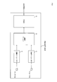
以下、図2を参照して本実施例の音源位置判定装置の構成を説明する。同図に示すように本実施例の音源位置判定装置1は、車両の内部から到来した音を収音しやすい位置に配置されたマイクロホン10-1(または10-3)と、車両の外部から到来した音を収音しやすい位置に配置されたマイクロホン10-2(または10-3)と、第1パワー計算部11と、第2パワー計算部12と、パワー比計算部13と、判定部14を含む。
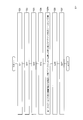
以下、図3を参照して本実施例の音源位置判定装置1の各構成要件の動作を説明する。第1パワー計算部11は、同時刻であるものと取り扱う旨予め定めた所定の時間区間T内において車両内に取り付けられたマイクロホン10-1(または10-3)で収音された音響信号の短時間平均パワー(第1のパワー)を計算する(S11)。例えば離散時刻tにおけるパワーを過去Nサンプルの平均パワーとして次式で計算する。

xi(t):時刻tにおける入力信号。Pi(t);短時間平均パワー、N:平均する時間長(sample)であり、100ms~10s程度に相当するサンプル数に設定する。
xi(t):時刻tにおける入力信号。Pi(t);短時間平均パワー、N:平均する時間長(sample)であり、100ms~10s程度に相当するサンプル数に設定する。
第2パワー計算部12は、第1パワー計算部11と同様に、同時刻であるものと取り扱う旨予め定めた所定の時間区間T内において車両外に設置されたマイクロホン10-2(または10-3)で収音された音響信号の短時間平均パワー(第2のパワー)を計算する(S12)。
パワー比計算部13は、第1のパワーと第2のパワーのパワー比を計算する(S13)。
判定部14は、パワー比と所定の閾値を比較して、パワー比があらかじめ設定した閾値を超えるか否かで、所定の時間区間T内に収音された音が車両の内部と外部いずれから到来したかを判定する(S14)。
実施例1の音源位置判定装置1、音源位置判定方法により、車両に設置されたマイクロホンで収音された音響信号に対応する音源が、車両の内部と外部のいずれに位置するかを判別できる。
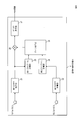
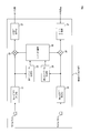
以下、図4を参照して実施例2の音源位置判定装置の構成を説明する。同図に示すように本実施例の音源位置判定装置2は、車両の内部から到来した音を収音しやすい位置に配置されたマイクロホン10-1(または10-3)と、車両の外部から到来した音を収音しやすい位置に配置されたマイクロホン10-2(または10-3)と、第1STFT計算部21と、第2STFT計算部22と、第1スペクトル計算部23と、第2スペクトル計算部24と、ゲイン計算部25と、ゲイン乗算部26と、STIFT計算部27を含む。
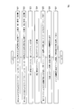
以下、図5を参照して本実施例の音源位置判定装置2の各構成要件の動作を説明する。第1STFT計算部21は、車両内に取り付けられたマイクロホン10-1(または10-3)で収音された音響信号の周波数領域表現である短時間フーリエ変換(第1信号)を計算する(S21)。第1STFT計算部21は、ハニング窓などを乗算してから短時間フーリエ変換をしてもよい。
第2STFT計算部22は、第1STFT計算部21と同様に、車両外に設置されたマイクロホン10-2(または10-3)で収音された音響信号の周波数領域表現である短時間フーリエ変換(第2信号)を計算する(S22)。
第1スペクトル計算部23は、第1信号のスペクトル(第1スペクトル)を計算する(S23)。短時間フーリエ変換後の信号をX(ω)とすれば、スペクトルP(ω)=X(ω)2である。ただし、X(ω)は周波数領域に変換したマイク信号の複素数である。ωは周波数。また、パワースペクトルP(ω)=|X(ω)|でもよい。
第2スペクトル計算部24は、第1スペクトル計算部23と同様に、第2信号のスペクトル(第2スペクトル)を計算する(S24)。
ゲイン計算部25は、第2スペクトルQ(ω)に所定の減算係数αを乗算して、第1スペクトルP(ω)からαQ(ω)を減算した値(S(ω))と第1スペクトルP(ω)の比をゲインG(ω)として計算する(S25)。減算係数はあらかじめ設定される値であり、0.1~10.0程度の値をとる。より詳細には、ゲイン計算部25は以下の式に基づいてゲインG(ω)を計算する。
S(ω)=P(ω)―α・Q(ω)
G(ω)=S(ω)/P(ω)
ゲイン乗算部26は、ゲイン計算部25で計算されたゲインG(ω)を、第1信号に乗算してゲイン乗算信号を出力する(S26)。
G(ω)=S(ω)/P(ω)
ゲイン乗算部26は、ゲイン計算部25で計算されたゲインG(ω)を、第1信号に乗算してゲイン乗算信号を出力する(S26)。
STIFT計算部27はゲイン乗算信号を逆フーリエ変換して時間領域表現とした信号を車両の内部音として出力する(S27)。
実施例2の音源位置判定装置2、音源位置判定方法により、車両に設置されたマイクロホンで収音された音響信号に対応する音源が、車両の内部と外部のいずれに位置するかを判別できる。また、車内から発せられた音と車外から発せられた音を分離することで音声アシスタントの精度向上や上述したコミュニケーションをするためのノイズリダクションを実現することができる。
[変形例]
以下、図6を参照して、実施例2の信号に対する処理を逆にすることで、車両の外部の音を抽出する音源位置判定装置2Aの構成を説明する。同図に示すように、本変形例の音源位置判定装置2Aは、車両の内部から到来した音を収音しやすい位置に配置されたマイクロホン10-1(または10-3)と、車両の外部から到来した音を収音しやすい位置に配置されたマイクロホン10-2(または10-3)と、第1STFT計算部21と、第2STFT計算部22と、第1スペクトル計算部23と、第2スペクトル計算部24と、ゲイン計算部25Aと、ゲイン乗算部26と、STIFT計算部27を含み、ゲイン計算部25A以外の構成は実施例2の音源位置判定装置2と同様である。
以下、図6を参照して、実施例2の信号に対する処理を逆にすることで、車両の外部の音を抽出する音源位置判定装置2Aの構成を説明する。同図に示すように、本変形例の音源位置判定装置2Aは、車両の内部から到来した音を収音しやすい位置に配置されたマイクロホン10-1(または10-3)と、車両の外部から到来した音を収音しやすい位置に配置されたマイクロホン10-2(または10-3)と、第1STFT計算部21と、第2STFT計算部22と、第1スペクトル計算部23と、第2スペクトル計算部24と、ゲイン計算部25Aと、ゲイン乗算部26と、STIFT計算部27を含み、ゲイン計算部25A以外の構成は実施例2の音源位置判定装置2と同様である。
音源位置判定装置2Aは、実施例2と同様にステップS21~S24を実行する。ゲイン計算部25Aは、第1スペクトルP(ω)に所定の減算係数βを乗算し、第2スペクトルQ(ω)からβP(ω)を減算した値(S’(ω))と第2スペクトルQ(ω)の比をゲインG’(ω)として計算する(S25A)。減算係数はあらかじめ設定される値である。より詳細には、ゲイン計算部25Aは以下の式に基づいてゲインG’(ω)を計算する。
S’(ω)=Q(ω)―β・P(ω)
G’(ω)=S’(ω)/Q(ω)
G’(ω)=S’(ω)/Q(ω)
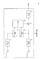
以下、図8を参照して、実施例2の音源位置判定装置2とその変形例の音源位置判定装置2Aを組み合わせて車両内部と外部の音を同時に抽出可能とした実施例3の音源位置判定装置3の構成を説明する。同図に示すように、本実施例の音源位置判定装置3は、車両の内部から到来した音を収音しやすい位置に配置されたマイクロホン10-1(または10-3)と、車両の外部から到来した音を収音しやすい位置に配置されたマイクロホン10-2(または10-3)と、第1STFT計算部21と、第2STFT計算部22と、第1スペクトル計算部23と、第2スペクトル計算部24と、ゲイン計算部35と、ゲイン乗算部26(内部音抽出側、外部音抽出側に一つずつ、計2個)と、STIFT計算部27(内部音抽出側、外部音抽出側に一つずつ、計2個)を含み、ゲイン計算部35以外の構成は実施例2の音源位置判定装置2またはその変形例の音源位置判定装置2Aと同様である。ゲイン計算部35は、実施例2と同様にステップS25を実行し、さらに変形例と同様にステップS25Aを実行する(S35)。
具体的には、ゲイン計算部35は、第2スペクトルQ(ω)に所定の減算係数αを乗算して第1スペクトルP(ω)から減算した値S(ω)と、第1スペクトルP(ω)の比を第1のゲインG(ω)として計算し、第1スペクトルP(ω)に所定の減算係数βを乗算して第2スペクトルQ(ω)から減算した値S’(ω)と、第2スペクトルQ(ω)の比を第2のゲインG’(ω)として計算する(S35)。
STIFT計算部27は、計算した第1のゲインG(ω)を第1信号に乗算してなる第1のゲイン乗算信号を時間領域表現とした信号を車両の内部音として出力し、計算した第2のゲインG’(ω)を第2信号に乗算してなる第2のゲイン乗算信号を時間領域表現とした信号を車両の外部音として出力する(S27)。残りの処理については、実施例2または変形例における対応する処理と同様である。
実施例3の音源位置判定装置3によれば、内部音抽出と外部音抽出において、共通する処理は一度行えばよいので、演算量のコストを減らすことができる。
実施例4の音源位置判定装置4は、実施例1の音源位置判定装置1の前段に実施例3の音源位置判定装置3を組み合わせて構成されている。
具体的には、パワー比計算部13は、ステップS27で出力された車両の内部音と車両の外部音のパワー比を計算する(S13)。判定部14は、パワー比に基づき、時間区間T内に収音された音が、車両の内部と外部いずれから到来したかを判定する(S14)。
実施例4の音源位置判定装置4によれば、内部音、外部音の抽出をしてから、音源が車両の内部と外部のいずれに位置するかを判別するため、さらに高精度に判別を行うことが出来る。
<補記>
本発明の装置は、例えば単一のハードウェアエンティティとして、キーボードなどが接続可能な入力部、液晶ディスプレイなどが接続可能な出力部、ハードウェアエンティティの外部に通信可能な通信装置(例えば通信ケーブル)が接続可能な通信部、CPU(Central Processing Unit、キャッシュメモリやレジスタなどを備えていてもよい)、メモリであるRAMやROM、ハードディスクである外部記憶装置並びにこれらの入力部、出力部、通信部、CPU、RAM、ROM、外部記憶装置の間のデータのやり取りが可能なように接続するバスを有している。また必要に応じて、ハードウェアエンティティに、CD-ROMなどの記録媒体を読み書きできる装置(ドライブ)などを設けることとしてもよい。このようなハードウェア資源を備えた物理的実体としては、汎用コンピュータなどがある。
本発明の装置は、例えば単一のハードウェアエンティティとして、キーボードなどが接続可能な入力部、液晶ディスプレイなどが接続可能な出力部、ハードウェアエンティティの外部に通信可能な通信装置(例えば通信ケーブル)が接続可能な通信部、CPU(Central Processing Unit、キャッシュメモリやレジスタなどを備えていてもよい)、メモリであるRAMやROM、ハードディスクである外部記憶装置並びにこれらの入力部、出力部、通信部、CPU、RAM、ROM、外部記憶装置の間のデータのやり取りが可能なように接続するバスを有している。また必要に応じて、ハードウェアエンティティに、CD-ROMなどの記録媒体を読み書きできる装置(ドライブ)などを設けることとしてもよい。このようなハードウェア資源を備えた物理的実体としては、汎用コンピュータなどがある。
ハードウェアエンティティの外部記憶装置には、上述の機能を実現するために必要となるプログラムおよびこのプログラムの処理において必要となるデータなどが記憶されている(外部記憶装置に限らず、例えばプログラムを読み出し専用記憶装置であるROMに記憶させておくこととしてもよい)。また、これらのプログラムの処理によって得られるデータなどは、RAMや外部記憶装置などに適宜に記憶される。
ハードウェアエンティティでは、外部記憶装置(あるいはROMなど)に記憶された各プログラムとこの各プログラムの処理に必要なデータが必要に応じてメモリに読み込まれて、適宜にCPUで解釈実行・処理される。その結果、CPUが所定の機能(上記、…部、…手段などと表した各構成要件)を実現する。
本発明は上述の実施形態に限定されるものではなく、本発明の趣旨を逸脱しない範囲で適宜変更が可能である。また、上記実施形態において説明した処理は、記載の順に従って時系列に実行されるのみならず、処理を実行する装置の処理能力あるいは必要に応じて並列的にあるいは個別に実行されるとしてもよい。
既述のように、上記実施形態において説明したハードウェアエンティティ(本発明の装置)における処理機能をコンピュータによって実現する場合、ハードウェアエンティティが有すべき機能の処理内容はプログラムによって記述される。そして、このプログラムをコンピュータで実行することにより、上記ハードウェアエンティティにおける処理機能がコンピュータ上で実現される。
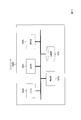
上述の各種の処理は、図10に示すコンピュータの記録部10020に、上記方法の各ステップを実行させるプログラムを読み込ませ、制御部10010、入力部10030、出力部10040などに動作させることで実施できる。
この処理内容を記述したプログラムは、コンピュータで読み取り可能な記録媒体に記録しておくことができる。コンピュータで読み取り可能な記録媒体としては、例えば、磁気記録装置、光ディスク、光磁気記録媒体、半導体メモリ等どのようなものでもよい。具体的には、例えば、磁気記録装置として、ハードディスク装置、フレキシブルディスク、磁気テープ等を、光ディスクとして、DVD(Digital Versatile Disc)、DVD-RAM(Random Access Memory)、CD-ROM(Compact Disc Read Only Memory)、CD-R(Recordable)/RW(ReWritable)等を、光磁気記録媒体として、MO(Magneto-Optical disc)等を、半導体メモリとしてEEP-ROM(Electrically Erasable and Programmable-Read Only Memory)等を用いることができる。
また、このプログラムの流通は、例えば、そのプログラムを記録したDVD、CD-ROM等の可搬型記録媒体を販売、譲渡、貸与等することによって行う。さらに、このプログラムをサーバコンピュータの記憶装置に格納しておき、ネットワークを介して、サーバコンピュータから他のコンピュータにそのプログラムを転送することにより、このプログラムを流通させる構成としてもよい。
このようなプログラムを実行するコンピュータは、例えば、まず、可搬型記録媒体に記録されたプログラムもしくはサーバコンピュータから転送されたプログラムを、一旦、自己の記憶装置に格納する。そして、処理の実行時、このコンピュータは、自己の記録媒体に格納されたプログラムを読み取り、読み取ったプログラムに従った処理を実行する。また、このプログラムの別の実行形態として、コンピュータが可搬型記録媒体から直接プログラムを読み取り、そのプログラムに従った処理を実行することとしてもよく、さらに、このコンピュータにサーバコンピュータからプログラムが転送されるたびに、逐次、受け取ったプログラムに従った処理を実行することとしてもよい。また、サーバコンピュータから、このコンピュータへのプログラムの転送は行わず、その実行指示と結果取得のみによって処理機能を実現する、いわゆるASP(Application Service Provider)型のサービスによって、上述の処理を実行する構成としてもよい。なお、本形態におけるプログラムには、電子計算機による処理の用に供する情報であってプログラムに準ずるもの(コンピュータに対する直接の指令ではないがコンピュータの処理を規定する性質を有するデータ等)を含むものとする。
また、この形態では、コンピュータ上で所定のプログラムを実行させることにより、ハードウェアエンティティを構成することとしたが、これらの処理内容の少なくとも一部をハードウェア的に実現することとしてもよい。
Claims (8)
- 閉空間の内部から到来した音を収音しやすい位置に配置される第1マイクロホンと、
閉空間の外部から到来した音を収音しやすい位置に配置される第2マイクロホンと、
同時刻であるものと取り扱う旨予め定めた所定の時間区間内において前記第1マイクロホンで収音された音響信号と、前記時間区間内において前記第2マイクロホンで収音された音響信号のパワー比を計算するパワー比計算部と、
前記パワー比に基づき、前記時間区間内に収音された音が、前記閉空間の内部と外部いずれから到来したかを判定する判定部を含む
音源位置判定装置。 - 閉空間の内部から到来した音を収音しやすい位置に配置される第1マイクロホンと、
閉空間の外部から到来した音を収音しやすい位置に配置される第2マイクロホンと、
前記第1マイクロホンで収音された音響信号の周波数領域表現である第1信号のスペクトルである第1スペクトルを計算する第1スペクトル計算部と、
前記第2マイクロホンで収音された音響信号の周波数領域表現である第2信号のスペクトルである第2スペクトルを計算する第2スペクトル計算部と、
前記第1スペクトルと前記第2スペクトルとを用いて、前記車両の内部から到来した音を強調するゲインを計算するゲイン計算部と、
計算したゲインを前記第1信号に乗算してなるゲイン乗算信号を時間領域表現とした信号を前記閉空間の内部音として出力するSTIFT計算部を含む
音源位置判定装置。 - 閉空間の内部から到来した音を収音しやすい位置に配置される第1マイクロホンと、
閉空間の外部から到来した音を収音しやすい位置に配置される第2マイクロホンと、
前記第1マイクロホンで収音された音響信号の周波数領域表現である第1信号のスペクトルである第1スペクトルを計算する第1スペクトル計算部と、
前記第2マイクロホンで収音された音響信号の周波数領域表現である第2信号のスペクトルである第2スペクトルを計算する第2スペクトル計算部と、
前記第1スペクトルと前記第2スペクトルとを用いて、前記車両の外部から到来した音を強調するゲインを計算するゲイン計算部と、
計算したゲインを前記第2信号に乗算してなるゲイン乗算信号を時間領域表現とした信号を前記閉空間の外部音として出力するSTIFT計算部を含む
音源位置判定装置。 - 閉空間の内部から到来した音を収音しやすい位置に配置される第1マイクロホンと、
閉空間の外部から到来した音を収音しやすい位置に配置される第2マイクロホンと、
前記第1マイクロホンで収音された音響信号の周波数領域表現である第1信号のスペクトルである第1スペクトルを計算する第1スペクトル計算部と、
前記第2マイクロホンで収音された音響信号の周波数領域表現である第2信号のスペクトルである第2スペクトルを計算する第2スペクトル計算部と、
前記第1スペクトルと前記第2スペクトルとを用いて、前記車両の内部から到来した音を強調する第1のゲインと、前記車両の外部から到来した音を強調する第2のゲインを計算するゲイン計算部と、
計算した第1のゲインを前記第1信号に乗算してなる第1のゲイン乗算信号を時間領域表現とした信号を前記閉空間の内部音として出力し、計算した第2のゲインを前記第2信号に乗算してなる第2のゲイン乗算信号を時間領域表現とした信号を前記閉空間の外部音として出力するSTIFT計算部を含む
音源位置判定装置。 - 請求項4に記載の音源位置判定装置であって、
前記閉空間の内部音と前記閉空間の外部音のパワー比を計算するパワー比計算部と、
前記パワー比に基づき、前記時間区間内に収音された音が、前記閉空間の内部と外部いずれから到来したかを判定する判定部を含む
音源位置判定装置。 - 車両の内部から到来した音を収音しやすい位置に配置される第1マイクロホンと、
車両の外部から到来した音を収音しやすい位置に配置される第2マイクロホンと、
同時刻であるものと取り扱う旨予め定めた所定の時間区間内において前記第1マイクロホンで収音された音響信号と、前記時間区間内において前記第2マイクロホンで収音された音響信号のパワー比を計算するパワー比計算部と、
前記パワー比に基づき、前記時間区間内に収音された音が、前記車両の内部と外部いずれから到来したかを判定する判定部を含む
音源位置判定装置。 - 閉空間の内部から到来した音を収音しやすい位置に配置される第1マイクロホンと、閉空間の外部から到来した音を収音しやすい位置に配置される第2マイクロホンとを用いる音源位置判定方法であって、
同時刻であるものと取り扱う旨予め定めた所定の時間区間内において前記第1マイクロホンで収音された音響信号と、前記時間区間内において前記第2マイクロホンで収音された音響信号のパワー比を計算するステップと、
前記パワー比に基づき、前記時間区間内に収音された音が、前記閉空間の内部と外部いずれから到来したかを判定するステップを含む
音源位置判定方法。 - コンピュータを請求項1から6の何れかに記載の音源位置判定装置として機能させるプログラム。
Priority Applications (3)
| Application Number | Priority Date | Filing Date | Title |
|---|---|---|---|
| PCT/JP2020/012062 WO2021186631A1 (ja) | 2020-03-18 | 2020-03-18 | 音源位置判定装置、音源位置判定方法、プログラム |
| JP2022508716A JP7552683B2 (ja) | 2020-03-18 | 2020-03-18 | 音源位置判定装置、音源位置判定方法、プログラム |
| US17/911,393 US20230097089A1 (en) | 2020-03-18 | 2020-03-18 | Sound source position determination device, sound source position determination method, and program |
Applications Claiming Priority (1)
| Application Number | Priority Date | Filing Date | Title |
|---|---|---|---|
| PCT/JP2020/012062 WO2021186631A1 (ja) | 2020-03-18 | 2020-03-18 | 音源位置判定装置、音源位置判定方法、プログラム |
Publications (1)
| Publication Number | Publication Date |
|---|---|
| WO2021186631A1 true WO2021186631A1 (ja) | 2021-09-23 |
Family
ID=77768414
Family Applications (1)
| Application Number | Title | Priority Date | Filing Date |
|---|---|---|---|
| PCT/JP2020/012062 Ceased WO2021186631A1 (ja) | 2020-03-18 | 2020-03-18 | 音源位置判定装置、音源位置判定方法、プログラム |
Country Status (3)
| Country | Link |
|---|---|
| US (1) | US20230097089A1 (ja) |
| JP (1) | JP7552683B2 (ja) |
| WO (1) | WO2021186631A1 (ja) |
Families Citing this family (2)
| Publication number | Priority date | Publication date | Assignee | Title |
|---|---|---|---|---|
| US12154551B2 (en) * | 2021-03-30 | 2024-11-26 | Cerence Operating Company | Determining whether an acoustic event originated inside or outside a vehicle |
| CN118865973B (zh) * | 2024-08-06 | 2026-02-10 | 岚图汽车科技股份有限公司 | 车辆语音交互唤醒方法、装置、设备及存储介质 |
Citations (5)
| Publication number | Priority date | Publication date | Assignee | Title |
|---|---|---|---|---|
| JPS60175197A (ja) * | 1984-02-20 | 1985-09-09 | 松下電器産業株式会社 | 盗難防止装置 |
| JP2008042390A (ja) * | 2006-08-03 | 2008-02-21 | National Univ Corp Shizuoka Univ | 車内会話支援システム |
| JP2009258802A (ja) * | 2008-04-11 | 2009-11-05 | Nissan Motor Co Ltd | 車外情報提供装置および車外情報提供方法 |
| JP2012025270A (ja) * | 2010-07-23 | 2012-02-09 | Denso Corp | 車両用の音量制御装置および音量制御装置用のプログラム |
| US20130185065A1 (en) * | 2012-01-17 | 2013-07-18 | GM Global Technology Operations LLC | Method and system for using sound related vehicle information to enhance speech recognition |
Family Cites Families (4)
| Publication number | Priority date | Publication date | Assignee | Title |
|---|---|---|---|---|
| US9800983B2 (en) * | 2014-07-24 | 2017-10-24 | Magna Electronics Inc. | Vehicle in cabin sound processing system |
| US20170303037A1 (en) * | 2016-04-19 | 2017-10-19 | Panasonic Automotive Systems Company Of America, Division Of Panasonic Corporation Of North America | Enhanced audio landscape |
| US10614788B2 (en) * | 2017-03-15 | 2020-04-07 | Synaptics Incorporated | Two channel headset-based own voice enhancement |
| JP6973484B2 (ja) | 2017-06-12 | 2021-12-01 | ヤマハ株式会社 | 信号処理装置、遠隔会議装置、および信号処理方法 |
-
2020
- 2020-03-18 JP JP2022508716A patent/JP7552683B2/ja active Active
- 2020-03-18 WO PCT/JP2020/012062 patent/WO2021186631A1/ja not_active Ceased
- 2020-03-18 US US17/911,393 patent/US20230097089A1/en not_active Abandoned
Patent Citations (5)
| Publication number | Priority date | Publication date | Assignee | Title |
|---|---|---|---|---|
| JPS60175197A (ja) * | 1984-02-20 | 1985-09-09 | 松下電器産業株式会社 | 盗難防止装置 |
| JP2008042390A (ja) * | 2006-08-03 | 2008-02-21 | National Univ Corp Shizuoka Univ | 車内会話支援システム |
| JP2009258802A (ja) * | 2008-04-11 | 2009-11-05 | Nissan Motor Co Ltd | 車外情報提供装置および車外情報提供方法 |
| JP2012025270A (ja) * | 2010-07-23 | 2012-02-09 | Denso Corp | 車両用の音量制御装置および音量制御装置用のプログラム |
| US20130185065A1 (en) * | 2012-01-17 | 2013-07-18 | GM Global Technology Operations LLC | Method and system for using sound related vehicle information to enhance speech recognition |
Also Published As
| Publication number | Publication date |
|---|---|
| JPWO2021186631A1 (ja) | 2021-09-23 |
| US20230097089A1 (en) | 2023-03-30 |
| JP7552683B2 (ja) | 2024-09-18 |
Similar Documents
| Publication | Publication Date | Title |
|---|---|---|
| US20040001598A1 (en) | System and method for adaptive multi-sensor arrays | |
| JPH09212196A (ja) | 雑音抑圧装置 | |
| JP6151236B2 (ja) | 雑音抑圧装置、その方法及びプログラム | |
| JP7552683B2 (ja) | 音源位置判定装置、音源位置判定方法、プログラム | |
| US20230154480A1 (en) | Adl-ufe: all deep learning unified front-end system | |
| JP7428251B2 (ja) | 目的音信号生成装置、目的音信号生成方法、プログラム | |
| JP6320963B2 (ja) | 音声認識システム、クライアント装置、音声認識方法、プログラム | |
| JP4533126B2 (ja) | 近接音分離収音方法、近接音分離収音装置、近接音分離収音プログラム、記録媒体 | |
| JP6125953B2 (ja) | 音声区間検出装置、その方法、及びプログラム | |
| JP2011107650A (ja) | 音声特徴量算出装置、音声特徴量算出方法及び音声特徴量算出プログラム並びに音声認識装置 | |
| CN111226278B (zh) | 低复杂度的浊音语音检测和基音估计 | |
| US12183317B2 (en) | Call environment generation method, call environment generation apparatus, and program | |
| JP7461192B2 (ja) | 基本周波数推定装置、アクティブノイズコントロール装置、基本周波数の推定方法及び基本周波数の推定プログラム | |
| US12002445B2 (en) | Cancel filter coefficient generation method, cancel filter coefficient generation apparatus, and program | |
| JP7026358B2 (ja) | 回帰関数学習装置、回帰関数学習方法、プログラム | |
| JP7677431B2 (ja) | 発話フィードバック装置、発話フィードバック方法、プログラム | |
| JP4612468B2 (ja) | 信号抽出装置 | |
| JP2025037301A (ja) | 音圧予測システム、音圧予測装置、音圧予測方法、プログラム | |
| JP6538002B2 (ja) | 目的音集音装置、目的音集音方法、プログラム、記録媒体 | |
| JP6542705B2 (ja) | 発話検出装置、発話検出方法、プログラム、記録媒体 | |
| JP7375905B2 (ja) | フィルタ係数最適化装置、フィルタ係数最適化方法、プログラム | |
| JP6802145B2 (ja) | Snr推定装置、snr推定方法、プログラム | |
| CN112673422A (zh) | 连续发言估计装置、连续发言估计方法以及程序 | |
| JP6639590B2 (ja) | ヘッドセット | |
| JP2020022113A (ja) | 集音拡声装置、その方法、およびプログラム |
Legal Events
| Date | Code | Title | Description |
|---|---|---|---|
| 121 | Ep: the epo has been informed by wipo that ep was designated in this application |
Ref document number: 20925142 Country of ref document: EP Kind code of ref document: A1 |
|
| ENP | Entry into the national phase |
Ref document number: 2022508716 Country of ref document: JP Kind code of ref document: A |
|
| NENP | Non-entry into the national phase |
Ref country code: DE |
|
| 122 | Ep: pct application non-entry in european phase |
Ref document number: 20925142 Country of ref document: EP Kind code of ref document: A1 |