WO2021186625A1 - 無線通信システム、無線通信制御装置および方法 - Google Patents
無線通信システム、無線通信制御装置および方法 Download PDFInfo
- Publication number
- WO2021186625A1 WO2021186625A1 PCT/JP2020/012033 JP2020012033W WO2021186625A1 WO 2021186625 A1 WO2021186625 A1 WO 2021186625A1 JP 2020012033 W JP2020012033 W JP 2020012033W WO 2021186625 A1 WO2021186625 A1 WO 2021186625A1
- Authority
- WO
- WIPO (PCT)
- Prior art keywords
- wireless communication
- base station
- radio
- wireless
- information
- Prior art date
- Legal status (The legal status is an assumption and is not a legal conclusion. Google has not performed a legal analysis and makes no representation as to the accuracy of the status listed.)
- Ceased
Links
Images







Classifications
-
- H—ELECTRICITY
- H04—ELECTRIC COMMUNICATION TECHNIQUE
- H04W—WIRELESS COMMUNICATION NETWORKS
- H04W72/00—Local resource management
- H04W72/20—Control channels or signalling for resource management
-
- H—ELECTRICITY
- H04—ELECTRIC COMMUNICATION TECHNIQUE
- H04W—WIRELESS COMMUNICATION NETWORKS
- H04W72/00—Local resource management
- H04W72/50—Allocation or scheduling criteria for wireless resources
- H04W72/56—Allocation or scheduling criteria for wireless resources based on priority criteria
-
- H—ELECTRICITY
- H04—ELECTRIC COMMUNICATION TECHNIQUE
- H04W—WIRELESS COMMUNICATION NETWORKS
- H04W24/00—Supervisory, monitoring or testing arrangements
- H04W24/02—Arrangements for optimising operational condition
-
- H—ELECTRICITY
- H04—ELECTRIC COMMUNICATION TECHNIQUE
- H04W—WIRELESS COMMUNICATION NETWORKS
- H04W28/00—Network traffic management; Network resource management
- H04W28/16—Central resource management; Negotiation of resources or communication parameters, e.g. negotiating bandwidth or QoS [Quality of Service]
- H04W28/18—Negotiating wireless communication parameters
-
- H—ELECTRICITY
- H04—ELECTRIC COMMUNICATION TECHNIQUE
- H04W—WIRELESS COMMUNICATION NETWORKS
- H04W84/00—Network topologies
- H04W84/02—Hierarchically pre-organised networks, e.g. paging networks, cellular networks, WLAN [Wireless Local Area Network] or WLL [Wireless Local Loop]
- H04W84/10—Small scale networks; Flat hierarchical networks
- H04W84/12—WLAN [Wireless Local Area Networks]
-
- Y—GENERAL TAGGING OF NEW TECHNOLOGICAL DEVELOPMENTS; GENERAL TAGGING OF CROSS-SECTIONAL TECHNOLOGIES SPANNING OVER SEVERAL SECTIONS OF THE IPC; TECHNICAL SUBJECTS COVERED BY FORMER USPC CROSS-REFERENCE ART COLLECTIONS [XRACs] AND DIGESTS
- Y02—TECHNOLOGIES OR APPLICATIONS FOR MITIGATION OR ADAPTATION AGAINST CLIMATE CHANGE
- Y02D—CLIMATE CHANGE MITIGATION TECHNOLOGIES IN INFORMATION AND COMMUNICATION TECHNOLOGIES [ICT], I.E. INFORMATION AND COMMUNICATION TECHNOLOGIES AIMING AT THE REDUCTION OF THEIR OWN ENERGY USE
- Y02D30/00—Reducing energy consumption in communication networks
- Y02D30/70—Reducing energy consumption in communication networks in wireless communication networks
Definitions
- Embodiments of the present invention relate to wireless communication systems, wireless communication control devices and methods.
- a communication system (system) to which a wireless LAN (Local Area Network) is applied (hereinafter, may be referred to as a system) is a wireless communication system that can be used inexpensively in a frequency band that does not require a license, and therefore is rapidly becoming widespread.
- a large number of wireless LAN terminals coexist in the same area and interfere with each other (see, for example, Non-Patent Document 1). Therefore, a number of techniques have been proposed for minimizing the influence of interference between wireless LAN terminals and expanding the communication capacity of individual or the entire system.
- each wireless LAN access point (base station) (AP: Access Point) that interferes with each other acquires peripheral interference information, and uses this acquired information as wireless environment information as a wireless communication control device.
- the control server calculates the allocation of the frequency channel to each AP so that the throughput of the AP group is maximized, and returns the calculation result to each AP as control information.
- the control server needs to calculate the optimized parameter in consideration of the information of the terminal connected to the AP.
- the communication speed, the delay time, the number of terminals that can be connected, the range of the communication area, and the communication requirements are various.
- the requirements to be prioritized differ depending on the usage scene of the application and device using the wireless LAN.
- the 920 MHz band can be operated by two types in Japan: a specific low power radio station having a maximum transmission power of 20 mW and a land mobile station having a maximum transmission power of 250 mW. Therefore, in a given frequency bandwidth, the corresponding licenses have different maximum transmit powers, i.e., the radius of the area that can be covered. Such a difference in communication capability in implementation needs to be taken into consideration when optimizing parameters.
- the content of the applicable frequency rules differs depending on whether the system is used domestically or overseas, and the range of frequency channels supported also differs for each device. These factors also need to be taken into account when optimizing the parameters.
- the bandwidth of the frequency channel defined by the communication standard IEEE802.11ah is five types of bandwidths of 1, 2, 4, 8 and 16 MHz. Of these bandwidths, the frequency bandwidth allowed in Japan is only 1 MHz, while in some countries, multiple frequency bandwidths up to 16 MHz are allowed. As described above, the usage restrictions of the wireless communication system differ depending on the country in which the wireless communication device is operated. Further, since the frequency bandwidth includes a frequency bandwidth that is required and a frequency bandwidth that is treated as an option, the frequency bandwidth implemented in the system depends on the device. It may vary depending on cost and application.
- the requirements for wireless communication differ depending on the scenario in which the system is used and the type of application used in the system.
- the communication speed of wireless communication is a requirement that should be given the highest priority.
- the communication range of wireless communication is a requirement that should be given the highest priority. In this way, the requirements that should be given the highest priority differ depending on the scenario used and the type of application, so it is not sufficient for the user to uniformly optimize the throughput and communication capacity. there is a possibility.
- IEEE Std 802.11ahTM-2016 IEEE Standard for Information technology-Telecommunications and information exchange between systems Local and metropolitan area networks-Specific requirements, Part 11: Wireless LAN Medium Access Control (MAC) and Physical Layer (PHY) Specifications Sub 1GHz License Exempt Operation, IEEE Computer Society
- the present invention has been made in view of the above circumstances, and an object of the present invention is to provide a wireless communication system, a wireless communication control device, and a method capable of optimizing setting information related to wireless communication. To do.
- the wireless communication system is communicably connected to a wireless base station that performs wireless communication with the belonging wireless terminal and the wireless base station, and is based on the wireless environment information of the wireless base station.
- a wireless communication system including a wireless base station and a wireless communication control station that notifies information indicating parameters used for communication control of the wireless terminal, wherein the wireless communication control station is of a plurality of types in wireless communication.
- the radio is based on a determination unit that determines the priority condition among the requirement conditions according to the current use case of wireless communication, the requirement condition determined by the determination unit, and the radio environment information of the radio base station. It includes a setting unit for setting information indicating parameters used for communication control by the base station and the wireless terminal, and a transmission unit for transmitting the information set by the setting unit to the wireless base station.
- the wireless communication control device is a wireless communication control device that is communicably connected to a wireless base station that performs wireless communication with the belonging wireless terminal, and is a plurality of types of requirements in wireless communication.
- the wireless base is based on a determination unit that determines a priority condition among the conditions according to the current use case of wireless communication, a requirement condition determined by the determination unit, and wireless environment information of the wireless base station. It includes a setting unit for setting information indicating parameters used for communication control by the station and the wireless terminal, and a transmission unit for transmitting the information set by the setting unit to the wireless base station.
- the wireless communication method is a method performed by a wireless communication control device communicably connected to a wireless base station that performs wireless communication with the belonging wireless terminal, and is performed by a plurality of wireless communication methods.
- the wireless base station is determined based on the determination of the preferred condition among the types of requirements according to the current use case of wireless communication, the determined requirement condition, and the wireless environment information of the wireless base station. It also includes setting information indicating parameters used for communication control by the wireless terminal, and transmitting the set information to the wireless base station.
- setting information related to wireless communication can be optimized.
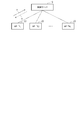
- FIG. 1 is a diagram showing an application example of a general wireless communication system.
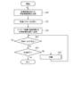
- FIG. 2 is a flowchart (flow chart) showing an example of control by a general wireless communication system.
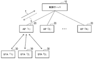
- FIG. 3 is a diagram showing an application example of the wireless communication system according to the embodiment of the present invention.
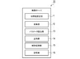
- FIG. 4 is a block diagram showing an example of the functional configuration of the control server.
- FIG. 5 is a flowchart showing an example of control by the wireless communication system according to the embodiment of the present invention.
- FIG. 6 is a diagram showing an example of parameters of components of a use case in a table format.
- FIG. 7 is a diagram showing an example of parameters of the components of the use case in a table format.
- FIG. 1 is a diagram showing an application example of a general wireless communication system.
- FIG. 2 is a flowchart (flow chart) showing an example of control by a general wireless communication system.
- FIG. 3 is a diagram showing an application example of the wireless communication system according to the embodiment of the present
- FIG. 8 is a diagram showing an example of points set for each requirement condition for the parameters of the components of the use case in a table format.
- FIG. 9 is a diagram showing an example of points set for each requirement condition for the parameters of the components of the use case in a table format.
- FIG. 10 is a diagram showing an example of points set for each requirement condition for the parameters of the components of the use case in a table format.
- FIG. 11 is a diagram showing an example of points set for each requirement condition for the parameters of the components of the use case in a table format.
- FIG. 12 is a diagram showing an example of points set for each requirement condition for the parameters of the components of the use case in a table format.
- FIG. 13 is a diagram showing an example of points set for each requirement condition for the parameters of the components of the use case in a table format.
- FIG. 14 is a diagram showing an example of calculation of points related to determination of the requirement condition to be given the highest priority in a table format.
- FIG. 15 is a diagram showing an example of calculation of points related to determination of the requirement condition to be given the highest priority in a table format.
- FIG. 16 is a diagram showing an example of calculation of points related to determination of the requirement condition to be given the highest priority in a table format.
- FIG. 17 is a diagram showing an example of calculation of points related to determination of the requirement condition to be given the highest priority in a table format.
- FIG. 18 is a diagram showing an example of calculation of points related to determination of the requirement condition to be given the highest priority in a table format.
- FIG. 19 is a diagram showing an example of calculation of points related to determination of the requirement condition to be given the highest priority in a table format.
- FIG. 20 is a flowchart showing a first example of control relating to parameter setting based on a requirement to be prioritized by the wireless communication system according to the embodiment of the present invention.
- FIG. 21 is a flowchart showing a second example of control relating to parameter setting based on a requirement to be prioritized by the wireless communication system according to the embodiment of the present invention.
- FIG. 22 is a block diagram showing an example of a hardware configuration of a control server of a wireless communication system according to an embodiment of the present invention.
- FIG. 1 is a diagram showing an application example of a general wireless communication system.
- the wireless communication system has a control server 10 and a plurality of wireless LAN access points (APs) 20.
- the control server 10 is sometimes called a wireless communication control station or a wireless communication control device.
- the AP20 is also sometimes called a radio base station.
- N AP20s are represented as AP “1”, AP “2” ... AP “N”.
- the control server 10 is communicably connected to each AP 20 in an environment where a plurality of AP 20s interfere with each other.
- each AP20 can carry out data communication with a wireless LAN terminal (STA) which is under the control, that is, which belongs to its own station and is not shown, in a wireless frame.
- STA wireless LAN terminal
- the wireless LAN terminal is sometimes called a communication terminal.
- AP20 and STA are sometimes referred to as wireless communication terminals in a broad sense.
- each AP 20 connected to the control server 10 can transmit wireless environment information to the control server 10.
- a shown in FIG. 1 corresponds to wireless environment information.
- This wireless environment information includes (1) frequency channel usage information such as AP and channel usage rates for which SSID (Service Set Identifier) can be confirmed, which is acquired by carrier sense in the vicinity. And (2) parameters currently set for the wireless device in each AP, such as the frequency channel used, channel bandwidth, transmit power value, and transmit time interval.
- the control server 10 collects wireless environment information from each AP 20.
- the control server 10 calculates the optimized parameters for each AP 20 using the wireless environment information under the condition that all AP 20s have the same specifications and the same communication capacity is required.
- the calculated parameters include, for example, frequency channel position, channel bandwidth, transmit power value, and transmit time interval.
- the calculation result is transmitted to each AP20 as control information. B shown in FIG. 1 corresponds to the control information.
- the AP20 Upon receiving the control information, the AP20 changes the corresponding set value of its own station according to the control information.
- the optimized parameters are calculated again based on the updated radio environment information, and the control information is transmitted to each AP20. NS.
- FIG. 2 is a flowchart showing an example of control by a general wireless communication system.
- the control server 10 collects wireless environment information from each AP 20 (S10), and calculates optimized parameters based on the collected information (S11).
- the control server 10 transmits information indicating the parameters calculated in S11 to each AP 20 as control information (S12).
- the control based on the parameters is executed.
- the control server 10 waits (S15), and when the occurrence of the control trigger is detected. (Yes in S13), the process returns to S10, and the processing after the collection of the wireless environment information is executed again.
- the optimum control information is considered in consideration of each requirement.
- the optimization is executed for one or more wireless communication terminals.
- optimal control information for example, in an environment in which wireless communication terminals having a plurality of different devices or usage environments and a plurality of different requirements coexist in the same environment while interfering with each other.
- Parameters and terms of use are calculated.
- the usage conditions are specifications of devices related to wireless communication, such as the maximum transmission power of a wireless communication terminal and the gain of an antenna.
- the optimum value of the frequency resource for each wireless communication terminal and the optimum value of the parameter set in the wireless communication terminal are calculated according to the collected wireless environment information.
- the usage constraint is, for example, a constraint on the maximum transmission power defined by the frequency rule in the frequency band in which the wireless communication terminal is used.
- the wireless communication system sets the initial setting value and the range of the control value at the time of optimization control based on the usage conditions, usage restrictions, and requirements according to the usage scene unique to each wireless communication terminal. And set them separately.
- the wireless communication system is the most in the use case as a result of comprehensive summing of the values scored for each requirement condition with respect to the parameters of the components of the use case of the communication standard. Determine the requirements that should be prioritized. This system calculates the optimum value of the parameter by using the optimum value calculation method according to the determined requirement condition.
- the usage conditions and usage restrictions peculiar to each wireless communication terminal are taken into consideration, and the assumed use cases are met.
- the optimum value calculation method is selected based on the required conditions, and the optimum value is calculated. As a result, the optimum control according to the individual requirements can be performed as compared with the optimum control in which only the specific wireless communication terminal and the specific requirements are assumed.
- the wireless communication system eliminates the ambiguity of the priority of the requirement condition by quantifying and determining the necessary requirement condition from the assumed use case, and is considered in the setting.
- the required condition can be uniquely determined.
- FIG. 3 is a diagram showing an application example of the wireless communication system according to the embodiment of the present invention.
- the wireless communication system has a control server 10 and a plurality of wireless LAN access points (APs) 20.
- APs wireless LAN access points
- N AP20s are represented as AP “1”, AP “2” ... AP “N”.
- the control server 10 is communicably connected to each AP 20 in an environment where a plurality of AP 20s interfere with each other.
- each AP20 can carry out data communication with the subordinate wireless LAN terminal (STA) 30 in a wireless frame.
- STA wireless LAN terminal
- FIG. 3 three STA30s under AP “1” are referred to as STA “1", STA “2” and STA “3".
- other APs can also carry out data communication with a subordinate STA (not shown) by a wireless frame.
- each AP 20 connected to the control server 10 can transmit wireless environment information to the control server 10.
- This wireless environment information includes (1) frequency channel usage information such as AP and channel usage rates whose SSID can be confirmed by carrier sense in the vicinity, and (2) parameters currently set as wireless devices in each AP. , For example the frequency channel used, channel bandwidth, and transmit power value, etc. (3) Range of available parameters, such as frequencies defined in a region such as a country or set as a device specification. Range and transmission power value range, (4) Current connection information, for example, the number and type of wireless LAN terminals connected to the AP, information on the channels that each wireless LAN terminal can use, and transmission power information. Etc., and (5) traffic information set or observed at the higher level in the wireless communication system and information of the application program.
- the control server 10 aggregates the information obtained from the AP 20 and sets the range of parameter values that can be set in each AP 20 as the range of controllable values.
- the control server 10 determines the requirements related to the wireless communication system according to the observed traffic information, the application information, or the use cases assumed by each AP 20 set on the control server 10. Further, the control server 10 sets the initial values of the optimum parameters related to the use case based on the current usage status of the peripheral frequency channels.
- the set initial value is transmitted from the control server 10 to each AP 20 as control information.
- the AP20 that has received the control information changes the set value related to the subordinate STA30 according to the control information.
- the optimum parameter is optimized based on the updated information such as the current connection information and the usage information of the surrounding frequency channels.
- the value is set again and transmitted to each AP20 as control information.
- FIG. 4 is a block diagram showing an example of a functional configuration of the control server.
- the control server 10 includes an initial value setting unit 11, a collection unit 12, a parameter calculation unit 13, a transmission unit 14, a control processing unit 15, and a storage unit 16.
- the parameter calculation unit 13 is a determination unit and a setting unit. The operation of each part will be described later.
- the control processing unit 15 controls the operations of the initial value setting unit 11, the collection unit 12, the parameter calculation unit 13, and the transmission unit 14.
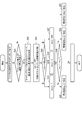
- FIG. 5 is a flowchart showing an example of control by the wireless communication system according to the embodiment of the present invention.
- the parameter values of the components of the use case of IEEE802.11ah are set by the initial value setting unit 11 of the control server 10 and stored in the storage unit 16 (S20).
- the range of set values related to each AP 20 is individually set based on the range of parameter values that can be used by the wireless communication system. Further, in the present embodiment, the required conditions to be prioritized are determined according to the observed traffic information, the application information, or the expected use case for each AP 20 set on the control server 10. In the present embodiment, for example, points are set for each requirement condition to be considered for the value of the parameter of the component of the use case. In the present embodiment, it is assumed that the sum of the points related to each component or the integrated value is the total score of each requirement condition, and the requirement condition having the highest score among each requirement condition is given the highest priority in the use case in this AP. It is considered a requirement to be.
- FIG. 6 is a diagram showing an example of parameters of the components of the use case in a table format. As shown in FIG. 6, in IEEE802.11ah, the requirements for resource setting differ depending on the use case used.
- the components of the use case are "number of terminals (reference number)", “traffic load”, “traffic direction”, “access frequency”, “propagation environment”, and “area range”. ..
- the types of parameters of the component “number of terminals” are “many (101 to)”, “medium (10 to 100)”, and “small (to 9)”.
- the parameter types of the component "traffic load” are "high (video (video), etc.)", “medium (data, etc.)” and “low (sensor, etc.)”.
- the types of parameters for the component "traffic direction” are “many uphill” (sometimes referred to as “many uphill”), “many downhill” (sometimes referred to as “many downhill”), and “many downhill”.
- the ascending direction and the descending direction are equivalent “(sometimes referred to as vertical equivalent).
- the parameter types of the component "access frequency” are "high (video, etc.)", “medium”, and “low (sensor, etc.)”.
- the types of parameters of the component "propagation environment” are “indoor [concrete]”, “indoor [wooden]”, “outdoor [city / city]”, and “outdoor [suburb]”.
- the parameter types of the component "area range” are “wide (300 [m] ⁇ )”, “medium (100 ⁇ 300 [m])” and “narrow ( ⁇ 100 [m] (less than 100 [m])). ) ”.
- FIG. 7 is a diagram showing an example of parameters of the components of the use case in a table format.
- FIG. 7 shows an example of the use case components assumed in IEEE802.11ah and the parameter values of the components in each use case.
- the use cases are divided into default, camera video transmission, monitoring, sensor, data distribution and data transfer.
- the value of the parameter of each component is shown for each use case and stored in the storage unit 16 of the control server 10.
- the value of the parameter related to the component "traffic load” in the use case “camera video transmission” is "high”.
- the "default” is a standard use case.
- the values of the parameters shown in FIG. 7 may be changed by an input operation by the system administrator. It should be noted that the value of the component parameter in the "default" use case may be changed to add a new use case related to this value.
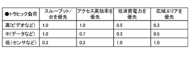
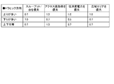
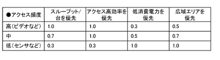
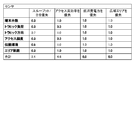
- FIGS. 8 to 13 are diagrams showing an example of the points set for each requirement condition for the parameters of the components of the use case in a table format. As shown in FIGS. 8 to 13, points are set for each requirement condition with respect to the value of the parameter of the component of the use case, and are stored in the storage unit 16 of the control server 10.
- the requirements are "priority is given to throughput per unit (throughput / unit is prioritized)", “priority is given to high access efficiency", and “priority is given to low power consumption”. And “priority is given to wide area”.
- the parameter values of the use case component "number of terminals" are "many (101 to)", “medium (10 to 100)", and “small (to 9)". Scores are set for each of the requirements "priority is given to throughput per unit”, “priority is given to high access efficiency”, “priority is given to low power consumption”, and “priority is given to wide area”. This score indicates the high or low priority of the requirement condition to be set in the value of the parameter of the component of the use case.
- the parameter value "many” of the component "number of terminals” has a relatively low priority related to the requirement "priority is given to throughput per unit", and the component "number of terminals" is used.
- the value of the parameter "small” means that the priority of the requirement condition "priority is given to the throughput per unit" is relatively high.
- each requirement condition is obtained for each of the parameter values of the use case component "traffic direction”, "many up directions”, “many down directions”, and "equal up and down directions”.
- a score is set for each of.
- each requirement is required for each of the parameter values "high (video, etc.)", “medium”, and “low (sensor, etc.)” of the use case component "access frequency”.
- a score is set for each of.
- the parameter values of the use case component "propagation environment” are "indoor [concrete]", “indoor [wooden]”, “outdoor [city / city]” and “outdoor [suburbs]".
- a score is set for each of the requirements.
- the parameter values of the use case component "area range” are "wide (300 [m] ⁇ )", “medium (100 ⁇ 300 [m])” and “narrow ( ⁇ 100)”. For each of [m]) ”, points are set for each of the required conditions.
- the initial value setting unit 11 of the control server 10 calculates the total number of points set for each component in a certain requirement condition for the target use case, and calculates this calculation for each of the requirement conditions. Do about.
- the initial value setting unit 11 determines that, among the required conditions, at least one of the required conditions having the highest score as the calculation result is the required condition to be given the highest priority. As an example of the above calculation, the initial value setting unit 11 uses the components "number of terminals”, “traffic load”, “traffic direction”, “access frequency”, “propagation environment”, and “area range” for each use case. Select one from the options with each item M i of.
- the collecting unit 12 of the control server 10 collects wireless environment information from each wireless communication terminal (S21).
- the parameter calculation unit 13 of the control server 10 calculates the optimum value of the parameter related to the wireless communication terminal based on the wireless environment information collected in S21 (S22).
- the control range may take into consideration the usage conditions of each wireless communication terminal, such as the maximum transmission power and the gain of the antenna. Further, when the optimum value of the parameter is calculated, the above-determined requirement condition can be taken into consideration.
- the optimum value of the transmission power value is not calculated, and the maximum value of the transmission power value is used. Based on the above-determined priority requirements, the calculation result of the optimum value of the parameter is different.
- FIG. 20 is a flowchart showing a first example of control relating to parameter setting based on a requirement to be prioritized by the wireless communication system according to the embodiment of the present invention.
- the parameter calculation unit 13 of the control server 10 is used to first set the upper limit of the transmission power value in setting the transmission power value by the AP and STA under the control target. Set the frequency band (channel group).
- the frequency bands open for RFID include a frequency band in which the upper limit of transmission power is 250 mW and a frequency band in which the upper limit of transmission power is 20 mW.
- the frequency bands open for RFID include a frequency band in which the upper limit of transmission power is 250 mW and a frequency band in which the upper limit of transmission power is 20 mW.
- the parameter calculation unit 13 shows that all of the AP and STA to be controlled have high output, in this case 250 mW of electric power. If it is possible to output (Yes in S33), the AP and STA to be controlled are set in the high output channel group in which 250 mW is the maximum transmission power (S34).
- the parameter calculation unit 13 is controlled by the AP so that the influence of interference with the surroundings is taken into consideration.
- STA is set to the normal channel group in which 20 mW is the maximum transmission power (S35). The same applies when No in S32.
- FIG. 21 is a flowchart showing a second example of control relating to parameter setting based on a requirement to be prioritized by the wireless communication system according to the embodiment of the present invention.
- the parameter calculation unit 13 of the control server 10 sets the channel bandwidth related to the AP to be controlled.
- the control for the default AP in the list of control targets when the requirement condition "throughput priority" is not the requirement condition that should be given the highest priority by itself (No in S41), the control with the peripheral wireless communication system is used.
- the parameter calculation unit 13 allocates the channel bandwidth of the AP to be controlled to 1 MHz, which is the narrowest bandwidth (S51).
- the parameter calculation unit 13 sets the maximum value BW of the channel bandwidth from, for example, the channel group and the country code model performance (S42).
- the parameter calculation unit 13 obtains bw_1 by the following equation (3) (S43).
- Bw_1 BW- (the number of controllable APs that the AP to be controlled is interfering with) ... Equation (3)
- the parameter calculation unit 13 determines whether the current traffic load corresponds to "low”, “medium”, or “high” (S44). When the current traffic load is “low”, the parameter calculation unit 13 sets bw_2 to "1" (S45). When the current traffic load is "medium”, the parameter calculation unit 13 sets bw_2 to "2" (S46). When the current traffic load is "high”, the parameter calculation unit 13 sets bw_2 to the maximum value BW (S47).
- Bw_1 and bw_2 are not integers, but are selected from the set of ⁇ 1,2,4,8,16 ⁇ . If bw_1 is 0 or less, 1 is set.
- the parameter calculation unit 13 sets the channel bandwidth to bw_1 (S49).
- the parameter calculation unit 13 sets the channel bandwidth to bw_2 (S49). In this way, as S22, the optimum value of the parameter is calculated based on the above-determined requirement condition and the range of the value of the parameter.
- the transmission unit 14 of the control server 10 transmits the calculated parameter value information as control information to each wireless communication terminal (S23). After that, when the control based on the parameter is executed after the lapse of a predetermined time, the occurrence of the control trigger is not detected (No in S24), and the control is not completed (No in S25), the control server. 10 waits (S26), returns to S21 when a control trigger occurs (Yes in S24), and collects wireless environment information again. When the control ends (Yes in S25), the series of processes shown in FIG. 5 ends.
- the parameter calculation unit 13 of the control server 10 sets the transmission time interval by the AP and STA under the control target.
- the requirement condition to be prioritized is "priority is given to access high efficiency" or when the value of the parameter of the above component "number of terminals" is "many (101 units or more)"
- each AP And the transmission time interval of the data frame at which the STA starts transmission is controlled.
- the time for executing carrier sense (hereinafter referred to as carrier sense time) to avoid collision of wireless signals is a certain time or more and the time calculated using random numbers. It is used as. Therefore, the time interval for transmitting the radio signal is inevitably increased.
- the parameter calculation unit 13 increases the probability that the wireless signals collide with each other even if the number of terminals coexisting in the same area increases by lengthening the time interval at which the wireless signals are transmitted, for example, by setting. Can be reduced.
- the parameter calculation unit 13 sets the time until the next transmission of the wireless signal, that is, the pause time, as the normal carrier sense. By setting it longer than the time, other terminals that have not yet completed transmission can preferentially start transmission.
- the RAW (Restricted Access Window) and TWT (Target Wake Time) defined in IEEE802.11ah have a function of limiting the time transmitted by the STA.
- whether or not to use these functions and their set values, for example, how to divide the group or the time that can be transmitted are determined by the requirement condition or the setting of the number of terminals by the parameter calculation unit 13. be able to.
- Control of the transmission time interval for avoiding collision of radio signals when a large number of terminals coexist causes communication overhead when there are few coexisting terminals, and thus reduces the time utilization rate of frequency resources. It ends up. Therefore, it is desirable to adaptively control it according to the environment or use case in which wireless communication is used as in one embodiment of the present invention.
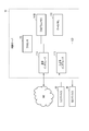
- FIG. 22 is a block diagram showing an example of the hardware configuration of the control server of the wireless communication system according to the embodiment of the present invention.
- the control server 10 according to the above embodiment is composed of, for example, a server computer or a personal computer, and includes a hardware processor 111A such as a CPU. Have. Then, the program memory 111B, the data memory 112, the input / output interface 113, and the communication interface 114 are connected to the hardware processor 111A via the bus 120. .. The same can be applied to AP20 and STA30.
- the communication interface 114 includes, for example, one or more wireless communication interface units (units), and enables information to be transmitted / received to / from the communication network NW.
- the wireless interface an interface adopting a low-power wireless data communication standard such as a wireless LAN is used.
- An input device 50 and an output device 60 for the administrator may be connected to the input / output interface 113.
- the program memory 111B is a non-volatile memory (non-volatile memory) that can be written and read at any time, such as an HDD (Hard Disk Drive) or an SSD (Solid State Drive), as a non-temporary tangible storage medium. It is used in combination with a non-volatile memory such as a ROM (Read Only Memory), and stores programs necessary for executing various control processes according to one embodiment.
- non-volatile memory non-volatile memory
- HDD Hard Disk Drive
- SSD Solid State Drive
- ROM Read Only Memory
- the data memory 112 is used as a tangible storage medium, for example, in combination with the above-mentioned non-volatile memory and a volatile memory such as RAM (RandomAccessMemory), and various processes are performed. It is used to store various data acquired and created in the process.
- RAM RandomAccessMemory
- the control server 10 has an initial value setting unit 11, a collection unit 12, a parameter calculation unit 13, a transmission unit 14, and control processing as processing function units by software. It can be configured as a data processing device having a unit 15.
- the storage unit 16 can be configured by using the data memory 112 shown in FIG. 22.
- the storage area in the data memory 112 is not an indispensable configuration in the control server 10, and is, for example, an external storage medium such as a USB (Universal Serial Bus) memory or a database server (database) arranged in the cloud. It may be an area provided in a storage device such as server).
- Each of the processing function units in each part of the control server 10 can be realized by reading the program stored in the program memory 111B by the hardware processor 111A and executing the program. Some or all of these processing function units may be in various other formats, including integrated circuits such as integrated circuits (ASIC (Application Specific Integrated Circuit)) or FPGA (Field-Programmable Gate Array) for specific applications. It may be realized.
- ASIC Application Specific Integrated Circuit
- FPGA Field-Programmable Gate Array
- the method described in each embodiment is a program (software means) that can be executed by a computer (computer), for example, a magnetic disk (floppy (registered trademark) disk (Floppy disk), hard disk, etc.), an optical disk, etc. It can be stored in a recording medium such as (optical disc) (CD-ROM, DVD, MO, etc.), semiconductor memory (ROM, RAM, Flash memory, etc.), or transmitted and distributed by a communication medium.
- the program stored on the medium side also includes a setting program for configuring the software means (including not only the execution program but also the table and the data structure) to be executed by the computer in the computer.
- a computer that realizes this device reads a program recorded on a recording medium, constructs software means by a setting program in some cases, and executes the above-mentioned processing by controlling the operation by the software means.
- the recording medium referred to in the present specification is not limited to distribution, and includes storage media such as magnetic disks and semiconductor memories provided in devices connected inside a computer or via a network.
- the present invention is not limited to the above embodiment, and can be variously modified at the implementation stage without departing from the gist thereof.
- each embodiment may be carried out in combination as appropriate, and in that case, the combined effect can be obtained.
- the above-described embodiment includes various inventions, and various inventions can be extracted by a combination selected from a plurality of disclosed constituent requirements. For example, even if some constituent requirements are deleted from all the constituent requirements shown in the embodiment, if the problem can be solved and the effect is obtained, the configuration in which the constituent requirements are deleted can be extracted as an invention.
- Control server 20 ... Wireless LAN access point (AP) 30 ... Wireless LAN terminal (STA)
Landscapes
- Engineering & Computer Science (AREA)
- Computer Networks & Wireless Communication (AREA)
- Signal Processing (AREA)
- Mobile Radio Communication Systems (AREA)
Abstract
Description
そのため、無線LAN端末同士の干渉の影響を最小限にして、個々のまたは全体のシステムの通信容量が拡大されるための多数の技術が提案されている。
制御サーバは、AP群のスループット(throughput)が最大となるように、各APへの周波数チャネル(channel)の割り当てを算出し、算出結果を制御情報として各APへ返送する。
なおかつ、無線LANを使用するアプリケーションおよびデバイスなどの利用シーン(scene)に応じて、優先されるべき要求条件は異なる。
そのため、所定の周波数帯域幅において、対応する免許によって、最大送信電力、すなわちカバー(cover)され得るエリアの半径が異なる。
このような実装上の通信能力の差は、パラメータの最適化が行なわれる上で考慮される必要がある。
さらに、上記周波数帯域幅には、必須とされている周波数帯域幅と、オプション(option)扱いとされている周波数帯域幅とが存在するため、システムに実装される周波数帯域幅は、デバイスに係るコスト(cost)および用途によって異なると考えられる。
また、農場または工場などでデータ(data)通信がなされる際は、無線通信の通信範囲が、最も優先されるべき要求条件である。
このように、使用されるシナリオおよびアプリケーションの種類によって、最も優先されるべき要求条件が異なるため、一様にスループットおよび通信容量の最適化が実施されるだけではユーザ(user)にとって不十分である可能性がある。
このため、各デバイスおよび利用シーンに応じた利用制約および要求条件が反映された最適化を実現することが必要である。
まず、上記一実施形態の理解を容易にするために、一般的な無線通信システムについて説明する。
図1は、一般的な無線通信システムの適用例を示す図である。
図1に示された例では、無線通信システムは、制御サーバ10および複数の無線LANアクセスポイント(AP)20を有する。制御サーバ10は無線通信制御局または無線通信制御装置と呼ばれることもある。また、AP20は、無線基地局と呼ばれることもある。
また、各AP20は、配下である、つまり自局に帰属する図示しない無線LAN端末(STA)との間でデータ通信を無線フレーム(frame)で実施可能である。無線LAN端末は通信端末と称されることもある。AP20およびSTAが広義の無線通信端末と称されることもある。
この無線環境情報は、(1)周辺でのキャリアセンス(carrier sense)により取得される、SSID(Service Set Identifier)が確認され得るAPおよびチャネルの使用率などの、周波数チャネルの利用情報の他、および(2)各APで無線デバイスについて現在設定されているパラメータ、例えば使用される周波数チャネル、チャネル帯域幅、送信電力値、および送信時間間隔など、が挙げられる。
計算結果は、制御情報として各AP20へ送信される。図1に示されるbは制御情報に対応する。
制御情報を受け取ったAP20は、この制御情報に従って、自局の該当の設定値を変更する。
まず、制御サーバ10は、各AP20から無線環境情報を収集し(S10)、この収集した情報をもとに、最適化されたパラメータを算出する(S11)。
ここで、制御サーバ10は、S11で算出されたパラメータを示す情報を制御情報として各AP20へ送信する(S12)。
図3に示された例では、無線通信システムは、制御サーバ10および複数の無線LANアクセスポイント(AP)20を有する。図3では、N個のAP20がAP「1」、AP「2」…AP「N」と表記される。このシステムでは、複数のAP20が互いに干渉しあう環境において、各AP20に制御サーバ10が通信可能に接続される。
この無線環境情報は、(1)周辺でのキャリアセンスによりSSIDが確認され得るAPおよびチャネルの使用率などの、周波数チャネルの利用情報、(2)各APで無線デバイスとして現在設定されているパラメータ、例えば使用される周波数チャネル、チャネル帯域幅、および送信電力値など、(3)使用可能なパラメータの範囲、例えば国などのリージョン(region)で制定されたり、デバイスの仕様として設定されたりする周波数範囲および送信電力値範囲、(4)現在の接続情報、例えばAPとの間で接続関係にある無線LAN端末の数および種類、各無線LAN端末が使用可能であるチャネルの情報、および送信電力情報など、および(5)無線通信システムにおける上位で設定または観測されるトラヒック(traffic)情報およびアプリケーションプログラムの情報、が挙げられる。
制御サーバ10は、観測されるトラヒック情報、アプリケーション情報、または制御サーバ10上で設定される、各AP20にて想定されるユースケースに従って、無線通信システムに係る要求条件を判定する。さらに、制御サーバ10は、周辺の周波数チャネルの現在の利用状況に基づいて、ユースケースに係る最適なパラメータの初期値を設定する。
制御情報を受け取ったAP20は、この制御情報に従って、配下のSTA30に係る設定値を変更する。
図4に示されるように、制御サーバ10は、初期値設定部11、収集部12、パラメータ算出部13、送信部14、制御処理部15および記憶部16を有する。パラメータ算出部13は、判定部および設定部である。各部の動作は後述する。制御処理部15は、初期値設定部11、収集部12、パラメータ算出部13および送信部14による動作を司る。
本実施形態では、IEEE802.11ahのユースケースの構成要素のパラメータの値が、制御サーバ10の初期値設定部11により設定されて記憶部16に記憶される(S20)。
本実施形態では、例えばユースケースの構成要素のパラメータの値に対して、考慮される要求条件毎に点数が設定される。
本実施形態では、各構成要素に係る点数の和、または積算値が各要求条件の総合点数であるとし、各要求条件のうち最も点数が高い要求条件を本APでのユースケースにおいて最も優先されるべき要求条件とみなされる。
図6に示されるように、IEEE802.11ahでは、利用されるユースケースに応じてリソース設定の要求条件が異なる。
構成要素「端末台数」のパラメータの種別は、「多(101台~)」、「中(10~100台)」および「少(~9台)」である。
構成要素「トラヒック負荷」のパラメータの種別は、「高(ビデオ(video)など)」、「中(データなど)」および「低(センサなど)」である。
構成要素「アクセス頻度」のパラメータの種別は、「高(ビデオなど)」、「中」、および「低(センサなど)」である。
構成要素「エリア範囲」のパラメータの種別は、「広(300[m]~)」、「中(100~300[m])」および「狭(~100[m](100[m]未満))」である。
図7では、IEEE802.11ahで想定されるユースケースの構成要素、および各ユースケースでの構成要素のパラメータの値の例が示される。
図8乃至13に示されるように、ユースケースの構成要素のパラメータの値に対し、要求条件毎に点数が設定され、制御サーバ10の記憶部16に格納される。図8乃至13に示された例では、要求条件は、「1台あたりのスループットを優先する(スループット/台を優先)」、「アクセス高効率を優先する」、「低消費電力を優先する」および「広域エリアを優先する」である。
上記の算出の例として、初期値設定部11は、ユースケースごとに、構成要素「端末台数」、「トラヒック負荷」、「トラヒック方向」、「アクセス頻度」、「伝搬環境」および「エリア範囲」の各項目Miで選択肢から一つ選択する。
計算したい優先項目lの評価式Plは下記の式(1)が挙げられる。

Pl=ΣMi(k, l) …式(2)
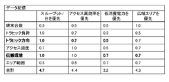
以下に、点数の合計の算出および最も優先されるべき要求条件の判定の具体例を説明する。
図14乃至図19は、最も優先されるべき要求条件の判定に係る点数の計算の一例を表形式で示す図である。図14乃至19で示される点数は図8乃至13に示される点数に対応する。なお、図15乃至19において、図14と異なる点数およびこの点数に係る構成要素が太字で示される。
このパラメータの最適な値が算出される際は、制御範囲が各無線通信端末の利用条件、例えば最大送信電力、およびアンテナのゲインなどが考慮され得る。また、パラメータの最適な値が算出される際は、上記判定された要求条件が考慮され得る。
このように上記判定された、優先すべき要求条件に基づき、パラメータの最適な値の算出結果が異なる。
この第1の例では、制御サーバ10のパラメータ算出部13は、制御対象である配下のAPおよびSTAによる送信電力値を設定する上で、まずは送信電力値の上限を設定するために、使用される周波数帯域(チャネルグループ(group))を設定する。
ここでは、制御対象のリスト内の初期設定のAPに対する制御として、要求条件「スループット優先」が、単独で最も優先されるべき要求条件でないときは(S41のNo)、周辺の無線通信システムとの干渉を回避するために、パラメータ算出部13は、制御対象であるAPに係るチャネル帯域幅を最も狭い帯域幅である1MHzに割り当てる(S51)。
以降、所定時間が経過した後に、パラメータに基づく制御が実行される場合は、制御トリガの発生が検出されない場合で(S24のNo)、制御が終了しないときは(S25のNo))、制御サーバ10は、待機(S26)し、制御トリガが発生したときは(S24のYes)、S21に戻り、無線環境情報の収集が再度実行される。制御が終了したときは(S25のYes)、図5に示される一連の処理が終了する。
この第3の例では、制御サーバ10のパラメータ算出部13は、制御対象である配下のAPおよびSTAによる送信時間間隔を設定する。ここでは、優先されるべき要求条件が「アクセス高効率を優先」となった場合または上記構成要素「端末台数」のパラメータの値が「多(101台~)」となった場合に、各APおよびSTAが送信開始するデータフレームの送信時間間隔が制御される。
パラメータ算出部13が、この、無線信号が送信される時間の間隔を例えば設定により長くすることで、同じエリア内に共存する端末の台数が多くなった場合でも、無線信号が互いに衝突する確率を減少させることができる。
また、キャリアセンス時間を設定により長くするのではなく、端末自身が無線信号を送信完了した後に、パラメータ算出部13が、無線信号が次回送信されるまでの時間、つまり休止時間を通常のキャリアセンス時間より長く設定することで、まだ送信が完了していない他の端末が優先的に送信を開始することができる。
図22に示された例では、上記の実施形態に係る制御サーバ10は、例えばサーバコンピュータ(server computer)またはパーソナルコンピュータ(personal computer)により構成され、CPU等のハードウエアプロセッサ(hardware processor)111Aを有する。そして、このハードウエアプロセッサ111Aに対し、プログラムメモリ(program memory)111B、データメモリ(data memory)112、入出力インタフェース(interface)113及び通信インタフェース114が、バス(bus)120を介して接続される。AP20、STA30についても同様であり得る。
入出力インタフェース113には、管理者用の入力デバイス50および出力デバイス60が接続されてもよい。
20…無線LANアクセスポイント(AP)
30…無線LAN端末(STA)
Claims (7)
- 帰属する無線端末との間で無線通信を行なう無線基地局と、前記無線基地局に通信可能に接続され、前記無線基地局の無線環境情報に基づいて、前記無線基地局および前記無線端末の通信制御に用いられるパラメータを示す情報を通知する無線通信制御局とを有する無線通信システムであって、
前記無線通信制御局は、
無線通信における複数種類の要求条件のうち優先される条件を無線通信の現在のユースケースに応じて判定する判定部と、
前記判定部により判定された要求条件、および前記無線基地局の無線環境情報に基づいて、前記無線基地局および前記無線端末による通信制御に用いられるパラメータを示す情報を設定する設定部と、
前記設定部により設定された情報を前記無線基地局へ送信する送信部と、
を備える無線通信システム。 - 前記無線通信制御局の前記設定部は、
前記判定部により判定された要求条件、および前記無線基地局の無線環境情報に基づいて、前記無線基地局および前記無線端末による通信制御に用いられるパラメータの値を示す情報と、前記パラメータの値の範囲を示す情報をそれぞれ設定する、
請求項1に記載の無線通信システム。 - 前記無線通信制御局は、
前記ユースケースを構成づける複数種類の要素のパラメータに対する優先度を示す点数が複数種類の前記要求条件の各々について設定された設定情報が記憶される記憶装置を有し、
前記無線通信制御局の判定部は、
前記記憶装置に記憶される設定情報を用いて、前記複数種類の要求条件のうち、前記複数種類の要素のパラメータに対する点数が最も高い条件を、現在のユースケースに応じた最も優先される要求条件として判定する、
請求項1に記載の無線通信システム。 - 帰属する無線端末との間で無線通信を行なう無線基地局に通信可能に接続される無線通信制御装置であって、
無線通信における複数種類の要求条件のうち優先される条件を無線通信の現在のユースケースに応じて判定する判定部と、
前記判定部により判定された要求条件、および前記無線基地局の無線環境情報に基づいて、前記無線基地局および前記無線端末による通信制御に用いられるパラメータを示す情報を設定する設定部と、
前記設定部により設定された情報を前記無線基地局へ送信する送信部と、
を備える無線通信制御装置。 - 前記設定部は、
前記判定部により判定された要求条件、および前記無線基地局の無線環境情報に基づいて、前記無線基地局および前記無線端末による通信制御に用いられるパラメータの初期値を示す情報と、前記パラメータの値の範囲を示す情報をそれぞれ設定する、
請求項4に記載の無線通信制御装置。 - 前記ユースケースを構成づける複数種類の要素のパラメータに対する優先度を示す点数が、複数種類の前記要求条件の各々について設定された設定情報が記憶される記憶装置を有し、
前記判定部は、
前記記憶装置に記憶される設定情報を用いて、前記複数種類の要求条件のうち、前記複数種類の要素のパラメータに対する点数が最も高い条件を、現在のユースケースにおける優先される要求条件として判定する、
請求項4に記載の無線通信制御装置。 - 帰属する無線端末との間で無線通信を行なう無線基地局に通信可能に接続される無線通信制御装置により行なわれる方法であって、
無線通信における複数種類の要求条件のうち優先される条件を無線通信の現在のユースケースに応じて判定することと、
前記判定された要求条件、および前記無線基地局の無線環境情報に基づいて、前記無線基地局および前記無線端末による通信制御に用いられるパラメータを示す情報を設定することと、
前記設定された情報を前記無線基地局へ送信することと、
を備える無線通信方法。
Priority Applications (3)
| Application Number | Priority Date | Filing Date | Title |
|---|---|---|---|
| US17/911,771 US12452865B2 (en) | 2020-03-18 | 2020-03-18 | Wireless communication system, and wireless communication control apparatus, and method |
| JP2022508710A JP7298773B2 (ja) | 2020-03-18 | 2020-03-18 | 無線通信システム、無線通信制御装置および方法 |
| PCT/JP2020/012033 WO2021186625A1 (ja) | 2020-03-18 | 2020-03-18 | 無線通信システム、無線通信制御装置および方法 |
Applications Claiming Priority (1)
| Application Number | Priority Date | Filing Date | Title |
|---|---|---|---|
| PCT/JP2020/012033 WO2021186625A1 (ja) | 2020-03-18 | 2020-03-18 | 無線通信システム、無線通信制御装置および方法 |
Publications (1)
| Publication Number | Publication Date |
|---|---|
| WO2021186625A1 true WO2021186625A1 (ja) | 2021-09-23 |
Family
ID=77771944
Family Applications (1)
| Application Number | Title | Priority Date | Filing Date |
|---|---|---|---|
| PCT/JP2020/012033 Ceased WO2021186625A1 (ja) | 2020-03-18 | 2020-03-18 | 無線通信システム、無線通信制御装置および方法 |
Country Status (3)
| Country | Link |
|---|---|
| US (1) | US12452865B2 (ja) |
| JP (1) | JP7298773B2 (ja) |
| WO (1) | WO2021186625A1 (ja) |
Families Citing this family (1)
| Publication number | Priority date | Publication date | Assignee | Title |
|---|---|---|---|---|
| US20250016852A1 (en) * | 2024-09-22 | 2025-01-09 | Intel Corporation | Apparatus, system, and method of server-based setting of wireless local area network (wlan) parameters |
Citations (2)
| Publication number | Priority date | Publication date | Assignee | Title |
|---|---|---|---|---|
| JP2016507183A (ja) * | 2013-01-11 | 2016-03-07 | インターデイジタル パテント ホールディングス インコーポレイテッド | Wlanオーバラッピング基本サービスセットのネットワーク内での通信のための方法および装置 |
| JP2018142896A (ja) * | 2017-02-28 | 2018-09-13 | 日本電信電話株式会社 | 無線通信システム、制御装置、アクセスポイント及び無線端末 |
Family Cites Families (6)
| Publication number | Priority date | Publication date | Assignee | Title |
|---|---|---|---|---|
| US9736703B2 (en) * | 2012-04-06 | 2017-08-15 | Plume Design, Inc. | Interference management and network performance optimization in dense WiFi networks |
| EP2905983B1 (en) * | 2012-11-12 | 2018-07-18 | Nippon Telegraph and Telephone Corporation | Wireless communication device, wireless communication system, and wireless communication method |
| JP6443117B2 (ja) * | 2015-02-20 | 2018-12-26 | 富士通株式会社 | 部品配置プログラム、部位品配置方法、および情報処理装置 |
| US10136342B2 (en) * | 2017-04-11 | 2018-11-20 | Cisco Technology, Inc. | System and method to facilitate wireless network optimization |
| JP6891733B2 (ja) * | 2017-08-28 | 2021-06-18 | 日本電信電話株式会社 | 無線通信システム、無線通信方法、無線基地局および制御局 |
| US11223962B2 (en) * | 2019-08-15 | 2022-01-11 | Cisco Technology, Inc. | Dynamic channel assignment driven by client analytics |
-
2020
- 2020-03-18 WO PCT/JP2020/012033 patent/WO2021186625A1/ja not_active Ceased
- 2020-03-18 JP JP2022508710A patent/JP7298773B2/ja active Active
- 2020-03-18 US US17/911,771 patent/US12452865B2/en active Active
Patent Citations (2)
| Publication number | Priority date | Publication date | Assignee | Title |
|---|---|---|---|---|
| JP2016507183A (ja) * | 2013-01-11 | 2016-03-07 | インターデイジタル パテント ホールディングス インコーポレイテッド | Wlanオーバラッピング基本サービスセットのネットワーク内での通信のための方法および装置 |
| JP2018142896A (ja) * | 2017-02-28 | 2018-09-13 | 日本電信電話株式会社 | 無線通信システム、制御装置、アクセスポイント及び無線端末 |
Non-Patent Citations (2)
| Title |
|---|
| IEEE802. 11AH, 22 October 2018 (2018-10-22), pages 1 - 15, Retrieved from the Internet <URL:https://www.11ahpc.org/pdf/usecase.pdf> [retrieved on 20200729] * |
| IEEE802.11AH, 22 October 2018 (2018-10-22), pages 1 - 4, Retrieved from the Internet <URL:https://www.11ahpc.org/pdf/80211ah.pdf> [retrieved on 20200729] * |
Also Published As
| Publication number | Publication date |
|---|---|
| US12452865B2 (en) | 2025-10-21 |
| US20230137745A1 (en) | 2023-05-04 |
| JPWO2021186625A1 (ja) | 2021-09-23 |
| JP7298773B2 (ja) | 2023-06-27 |
Similar Documents
| Publication | Publication Date | Title |
|---|---|---|
| CN101897131B (zh) | 系统信息块映射的方法、系统和装置 | |
| US8559410B2 (en) | Self-configuring, self-optimizing wireless local area network system | |
| JP2019033435A (ja) | 無線通信システム、集中制御局および可動基地局配置方法 | |
| US7085249B2 (en) | Dynamic QoS for integrated voice and data CDMA/1XRTT networks | |
| CN115066007B (zh) | 节能策略的确定方法、装置及存储介质 | |
| EP3691326A1 (en) | Method and device for network optimization | |
| KR20160014600A (ko) | 무선 통신 시스템의 장치 및 방법 | |
| CN112672364B (zh) | 策略配置方法、装置、相关设备及存储介质 | |
| US11546931B2 (en) | Systems and methods for UL scheduler optimization with a self-adjustment BSPR scheme | |
| JP2018011156A (ja) | 可動無線局制御方法、無線通信システム及び集中制御局 | |
| US10075379B2 (en) | Device and method for transmitting/receiving data in wireless communication system | |
| CN117528787B (zh) | 无线资源调度管理方法、装置、电子设备及可读存储介质 | |
| KR101924691B1 (ko) | 무선 통신에서 캐시 메모리를 이용하여 다수의 송신 노드에 데이터를 분산 저장하는 방법 및 장치 | |
| JP7298773B2 (ja) | 無線通信システム、無線通信制御装置および方法 | |
| US20130010747A1 (en) | Method and system for coexistence between wireless communication networks | |
| US12507295B2 (en) | Radios with simultaneous transmit and receive | |
| US10314083B2 (en) | Systems and methods for traffic offloading in multi-radio-access-technology networks | |
| WO2019054112A1 (ja) | 通信装置、無線通信システムおよびデータフロー制御方法 | |
| US12137473B2 (en) | Method for configuring a plurality of wireless access point devices and associated configuration device | |
| CN117598014A (zh) | 基于发射功率控制(tpc)的多链路选择 | |
| JP2012231238A (ja) | 基地局及び通信制御方法 | |
| Lim et al. | Dynamic power management in Wi-Fi Direct for future wireless serial bus | |
| WO2022264320A1 (ja) | 無線通信システム、無線通信方法、無線通信制御装置およびプログラム | |
| CN108449768B (zh) | 一种无线接入的调整方法及系统 | |
| US10349411B2 (en) | Assign band modes and channels to wireless nodes |
Legal Events
| Date | Code | Title | Description |
|---|---|---|---|
| 121 | Ep: the epo has been informed by wipo that ep was designated in this application |
Ref document number: 20926127 Country of ref document: EP Kind code of ref document: A1 |
|
| ENP | Entry into the national phase |
Ref document number: 2022508710 Country of ref document: JP Kind code of ref document: A |
|
| NENP | Non-entry into the national phase |
Ref country code: DE |
|
| 122 | Ep: pct application non-entry in european phase |
Ref document number: 20926127 Country of ref document: EP Kind code of ref document: A1 |
|
| WWG | Wipo information: grant in national office |
Ref document number: 17911771 Country of ref document: US |