WO2021186586A1 - 基地局及び端末 - Google Patents
基地局及び端末 Download PDFInfo
- Publication number
- WO2021186586A1 WO2021186586A1 PCT/JP2020/011814 JP2020011814W WO2021186586A1 WO 2021186586 A1 WO2021186586 A1 WO 2021186586A1 JP 2020011814 W JP2020011814 W JP 2020011814W WO 2021186586 A1 WO2021186586 A1 WO 2021186586A1
- Authority
- WO
- WIPO (PCT)
- Prior art keywords
- link
- processing unit
- signal processing
- base station
- terminal
- Prior art date
- Legal status (The legal status is an assumption and is not a legal conclusion. Google has not performed a legal analysis and makes no representation as to the accuracy of the status listed.)
- Ceased
Links
Images



Classifications
-
- H—ELECTRICITY
- H04—ELECTRIC COMMUNICATION TECHNIQUE
- H04W—WIRELESS COMMUNICATION NETWORKS
- H04W76/00—Connection management
- H04W76/10—Connection setup
- H04W76/15—Setup of multiple wireless link connections
-
- H—ELECTRICITY
- H04—ELECTRIC COMMUNICATION TECHNIQUE
- H04W—WIRELESS COMMUNICATION NETWORKS
- H04W72/00—Local resource management
- H04W72/04—Wireless resource allocation
-
- H—ELECTRICITY
- H04—ELECTRIC COMMUNICATION TECHNIQUE
- H04W—WIRELESS COMMUNICATION NETWORKS
- H04W84/00—Network topologies
- H04W84/02—Hierarchically pre-organised networks, e.g. paging networks, cellular networks, WLAN [Wireless Local Area Network] or WLL [Wireless Local Loop]
- H04W84/10—Small scale networks; Flat hierarchical networks
- H04W84/12—WLAN [Wireless Local Area Networks]
Definitions
- the embodiment relates to a base station and a terminal.
- a wireless LAN Local Area Network
- a wireless system that wirelessly connects a base station and a terminal.
- IEEE Std 802.11-2016 “ Figure 4-25 Establishing the IEEE 802.11 association” and “11.3 STA authentication and association”, 7 December 2016
- the challenge is to improve the speed and stability of wireless communication.
- the base station of the embodiment includes a first radio signal processing unit, a second radio signal processing unit, and a link management unit.
- the first radio signal processing unit is configured to be able to transmit and receive radio signals using the first band.
- the second radio signal processing unit is configured to be capable of transmitting and receiving radio signals using a second band different from the first band.
- the link management unit manages the link state of the first radio signal processing unit and the link state of the second radio signal processing unit. When the first radio signal processing unit and the second radio signal processing unit each execute association processing between the same terminal and establish a link, the link management unit multi-links from the terminal. When the request is received, the first radio signal processing unit and the second radio signal processing unit are used to establish a multi-link with the terminal.
- the base station of the embodiment can improve the speed and stability of wireless communication.
- FIG. 1 is a conceptual diagram showing an example of the overall configuration of the wireless system according to the embodiment.
- FIG. 2 is a block diagram showing an example of the configuration of a base station included in the wireless system according to the embodiment.
- FIG. 3 is a block diagram showing an example of the configuration of a terminal included in the wireless system according to the embodiment.
- FIG. 4 is a conceptual diagram showing a specific example of the format of the wireless frame in the wireless system according to the embodiment.
- FIG. 5 is a block diagram showing an example of the function of the base station included in the wireless system according to the embodiment.
- FIG. 6 is a block diagram showing an example of the function of the terminal included in the wireless system according to the embodiment.
- FIG. 7 is a flowchart showing an example of the operation of the wireless system according to the embodiment.
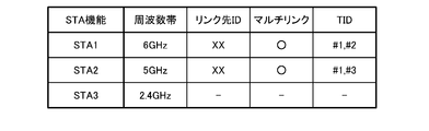
- FIG. 8 is a table showing an example of link management information in the wireless system according to the embodiment.
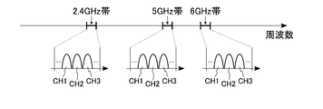
- FIG. 9 is a conceptual diagram showing an example of a band used for wireless communication in a wireless system according to a modified example of the embodiment.
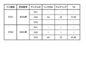
- FIG. 10 is a table showing an example of link management information in the wireless system according to the modified example of the embodiment.
- FIG. 1 shows an example of the configuration of the wireless system 1 according to the first embodiment.
- the wireless system 1 includes, for example, a base station 10, a terminal 20, and a server 30.
- the base station 10 is connected to the network NW and is used as a wireless LAN access point.
- the base station 10 can wirelessly distribute the data received from the network NW to the terminal 20.
- the base station 10 may be connected to the terminal 20 by using one type of band or a plurality of types of bands.
- the wireless connection between the base station 10 and the terminal 20 using a plurality of types of bands is referred to as "multi-link".
- Communication between the base station 10 and the terminal 20 is based on, for example, the IEEE 802.11 standard.
- the terminal 20 is a wireless terminal such as a smartphone or a tablet PC.
- the terminal 20 can send and receive data to and from the server 30 on the network NW via the base station 10 wirelessly connected.
- the terminal 20 may be another electronic device such as a desktop computer or a laptop computer.
- the terminal 20 may be any device that can communicate with at least the base station 10 and can execute the operations described later.
- the server 30 can hold various information, for example, holds content data for the terminal 20.
- the server 30 is connected to, for example, a network NW by wire, and is configured to be able to communicate with the base station 10 via the network NW.
- the server 30 may be capable of communicating with at least the base station 10. That is, the communication between the base station 10 and the server 30 may be wired or wireless.
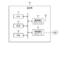
- FIG. 2 shows an example of the configuration of the base station 10 included in the wireless system 1 according to the first embodiment.
- the base station 10 includes, for example, a CPU (Central Processing Unit) 11, a ROM (Read Only Memory) 12, a RAM (Random Access Memory) 13, a wireless communication module 14, and a wired communication module 15. There is.
- a CPU Central Processing Unit
- ROM Read Only Memory
- RAM Random Access Memory
- the CPU 11 is a circuit capable of executing various programs, and controls the overall operation of the base station 10.
- the ROM 12 is a non-volatile semiconductor memory, and holds a program, control data, and the like for controlling the base station 10.
- the RAM 13 is, for example, a volatile semiconductor memory and is used as a work area of the CPU 11.
- the wireless communication module 14 is a circuit used for transmitting and receiving data by a wireless signal, and is connected to an antenna. Further, the wireless communication module 14 includes, for example, a plurality of communication modules corresponding to a plurality of frequency bands.
- the wired communication module 15 is a circuit used for transmitting and receiving data by a wired signal, and is connected to a network NW.
- FIG. 3 shows an example of the configuration of the terminal 20 included in the wireless system 1 according to the first embodiment.
- the terminal 20 includes, for example, a CPU 21, a ROM 22, a RAM 23, a wireless communication module 24, a display 25, and a storage 26.
- the CPU 21 is a circuit capable of executing various programs, and controls the overall operation of the terminal 20.
- the ROM 22 is a non-volatile semiconductor memory, and holds a program, control data, and the like for controlling the terminal 20.
- the RAM 23 is, for example, a volatile semiconductor memory and is used as a work area of the CPU 21.
- the wireless communication module 24 is a circuit used for transmitting and receiving data by a wireless signal, and is connected to an antenna. Further, the wireless communication module 24 includes, for example, a plurality of communication modules corresponding to a plurality of frequency bands.
- the display 25 displays, for example, a GUI (Graphical User Interface) corresponding to the application software. The display 25 may have a function as an input interface of the terminal 20.
- the storage 26 is a non-volatile storage device, and holds, for example, the system software of the terminal 20.
- the wireless system 1 executes data communication based on an OSI (Open Systems Interconnection) reference model.
- OSI Open Systems Interconnection
- the communication function has 7 layers (1st layer: physical layer, 2nd layer: data link layer, 3rd layer: network layer, 4th layer: transport layer, 5th layer: session layer, 6th layer. Layer: presentation layer, 7th layer: application layer).
- the data link layer includes, for example, an LLC (Logical Link Control) layer and a MAC (Media Access Control) layer.
- LLC Logical Link Control
- MAC Media Access Control
- the third to seventh layers are referred to as "upper layers" with reference to the data link layer.
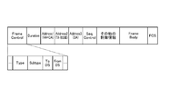
- FIG. 4 shows a specific example of the radio frame format in the radio system 1 according to the first embodiment.
- the radio frame includes, for example, a Frame Control field, a Duration field, an Address1 field, an Address2 field, an Address3 field, a Sequence Control field, other control information fields, a Frame Body field, and an FCS (Frame Check Sequence) field.
- the Frame Control field to other control information fields correspond to, for example, the MAC header included in the MAC frame.
- the Frame Body field corresponds to, for example, the MAC payload contained in the MAC frame.
- the FCS field is information added to detect a frame error.
- the Frame Control field indicates various control information, and includes, for example, a Type value, a Subtype value, a To DS (To Distribution System) value, and a From DS value.
- the Type value and Subtype value indicate the frame type of the wireless frame.
- the Type value "00” indicates that the wireless frame is a management frame.
- the Type value "01” indicates that the radio frame is a control frame.
- the Type value "10” indicates that the radio frame is a data frame. Further, the content of the wireless frame changes depending on the combination of the Type value and the Subtype value.
- To DS value indicates that the data is between terminals in the same IBSS.
- 10 indicates that the data frame is directed to the DS (Distribution System) from the outside.
- 01 indicates that the data frame goes out of the DS.
- 11 is used when configuring a mesh network.
- the Duration field indicates the planned period for using the wireless line.
- the Address field is used to indicate the BSSID, source address, destination address, sender terminal address, recipient terminal address.
- the Sequence Control field indicates the sequence number of the MAC frame and the fragment number for the fragment.
- the Frame Body field contains information according to the type of frame. For example, in the case of a data frame, data is stored.
- the FCS stores the error detection code of the MAC header and the Frame Body, and is used to determine the presence or absence of an error.
- the base station 10 is based on a request from a terminal 20 having a plurality of links established. Establish a multi-link between and.
- the base station 10 may be a trigger to establish a multi-link between the base station 10 and the terminal 20, but in the present specification, the multi-link is established based on the request from the terminal 20.
- multi-link processing the operation for establishing a multi-link between the base station 10 and the terminal 20 is referred to as "multi-link processing”.
- the functional configurations of the base station 10 and the terminal 20 related to the multi-link processing of the wireless system 1 according to the first embodiment will be described in order.
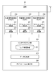
- FIG. 5 shows an example of the functional configuration of the base station 10 in the wireless system 1 according to the first embodiment.
- the base station 10 can function as, for example, a data processing unit 110, a link management unit 120, and radio signal processing units 130, 140, and 150.
- the data processing unit 110 can execute the processing of the LLC layer and the processing of the upper layer on the input data. For example, the data processing unit 110 outputs the data input from the server 30 via the network NW to the link management unit 120. Further, the data processing unit 110 transmits the data input from the link management unit 120 to the server 30 via the network NW.
- the link management unit 120 can execute, for example, a part of the processing of the MAC layer on the input data. Further, the link management unit 120 manages the link with the terminal 20 based on the notifications from the radio signal processing units 130, 140 and 150.
- the link management unit 120 includes the link management information 121.
- the link management information 121 includes, for example, information on a terminal 20 stored in the RAM 13 and wirelessly connected to the base station 10.
- the link management unit 120 detects in the link management information 121 that a plurality of links have been established for the same terminal 20, the link management unit 120 responds to a request from the link management unit 220 of the terminal 20 to perform multilink. To establish.
- Each of the radio signal processing units 130, 140, and 150 can execute, for example, a part of the processing of the MAC layer and the processing of the first layer on the input data or the radio signal. That is, each of the wireless signal processing units 130, 140, and 150 transmits and receives data between the base station 10 and the terminal 20 using wireless communication.
- the radio signal processing unit 130 handles a radio signal in the 2.4 GHz band.
- the radio signal processing unit 140 handles radio signals in the 5 GHz band.
- the radio signal processing unit 150 handles a radio signal in the 6 GHz band.
- the radio signal processing units 130, 140 and 150 may or may not share the antenna of the base station 10.
- each of the wireless signal processing units 130, 140, and 150 creates a wireless frame using the data input from the link management unit 120. Then, each of the radio signal processing units 130, 140, and 150 converts the radio frame into a radio signal and distributes the radio signal via the antenna of the base station 10. Further, each of the radio signal processing units 130, 140, and 150 converts the radio signal received via the antenna of the base station 10 into a radio frame, and outputs the data contained in the radio frame to the link management unit 120. ..
- the radio signal processing unit 130 includes an association processing unit 131 and an authentication processing unit 132.
- the radio signal processing unit 140 includes an association processing unit 141 and an authentication processing unit 142.
- the radio signal processing unit 150 includes an association processing unit 151 and an authentication processing unit 152.
- Each of the association processing units 131, 141, and 151 executes the protocol related to the association when the connection request of the terminal 20 is received.
- Each of the authentication processing units 132, 142, and 152 executes a protocol related to authentication following the connection request.
- FIG. 6 shows an example of the functional configuration of the terminal 20 in the wireless system 1 according to the first embodiment.
- the terminal 20 can function as, for example, a data processing unit 210, a link management unit 220, a radio signal processing unit 230, 240 and 250, and an application execution unit 260.
- the data processing unit 210 can execute the processing of the LLC layer and the processing of the upper layer on the input data. For example, the data processing unit 210 outputs the data input from the application execution unit 260 to the link management unit 220. Further, the data processing unit 210 outputs the data input from the link management unit 220 to the application execution unit 260.
- the link management unit 220 can execute, for example, a part of the processing of the MAC layer on the input data. Further, the link management unit 220 manages the link with the base station 10 based on the notifications from the radio signal processing units 230, 240 and 250.
- the link management unit 220 includes the link management information 221.
- the link management information 221 is stored in, for example, the RAM 23, and includes information on the base station 10 to which the terminal 20 is connected.
- the link management information 221 includes information similar to, for example, the link management information 121.
- the link management unit 220 when the link management unit 220 detects in the link management information 221 that a plurality of links for the same base station 10 have been established, the link management unit 220 requests the base station 10 to establish a multi-link.
- Each of the radio signal processing units 230, 240, and 250 can execute, for example, a part of the processing of the MAC layer and the processing of the first layer on the input data or the radio signal. That is, each of the wireless signal processing units 230, 240, and 250 transmits and receives data between the base station 10 and the terminal 20 using wireless communication.
- the radio signal processing unit 230 handles radio signals in the 2.4 GHz band.
- the radio signal processing unit 240 handles radio signals in the 5 GHz band.
- the radio signal processing unit 250 handles a radio signal in the 6 GHz band.
- the wireless signal processing units 230, 240 and 250 may or may not share the antenna of the terminal 20.
- each of the wireless signal processing units 230, 240, and 250 creates a wireless frame using the data input from the link management unit 220. Then, each of the wireless signal processing units 230, 240, and 250 converts the wireless frame into a wireless signal and distributes the wireless signal via the antenna of the terminal 20. Further, each of the wireless signal processing units 230, 240, and 250 converts the wireless signal received via the antenna of the terminal 20 into a wireless frame, and outputs the data contained in the wireless frame to the link management unit 220.
- the radio signal processing unit 230 includes an association processing unit 231 and an authentication processing unit 232.
- the radio signal processing unit 240 includes an association processing unit 241 and an authentication processing unit 242.
- the radio signal processing unit 250 includes an association processing unit 251 and an authentication processing unit 252.
- Each of the association processing units 231, 241 and 251 executes the protocol related to the association when the connection request of the base station 10 is received.
- Each of the authentication processing units 232, 242 and 252 executes a protocol related to authentication following the connection request.
- the application execution unit 260 executes an application that can use the data input from the data processing unit 210.
- the application execution unit 260 can display application information on the display 25. Further, the application execution unit 260 may operate based on the operation of the input interface.
- the wireless signal processing units 130, 140 and 150 of the base station 10 can be connected to the wireless signal processing units 230, 240 and 250 of the terminal 20, respectively. It is composed. Specifically, the wireless signal processing units 130 and 230 may be wirelessly connected using the 2.4 GHz band. The wireless signal processing units 140 and 240 may be wirelessly connected using the 5 GHz band. The wireless signal processing units 150 and 250 may be wirelessly connected using a 6 GHz band. Each radio signal processing unit may be referred to as a "STA function". That is, the wireless system 1 according to the first embodiment has a plurality of STA functions.
- the terminal 20 is used after a connection using a plurality of STA functions is established between the base station 10 and the terminal 20. Request the base station 10 to establish a multi-link.
- An example of the flow of the multi-link processing in the wireless system 1 according to the first embodiment will be described below.
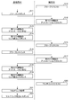
- FIG. 7 is a flowchart showing an example of multi-link processing in the wireless system 1 according to the first embodiment. As shown in FIG. 7, in the multi-link process in the first embodiment, for example, the processes of steps S10 to S22 are executed in order.
- the terminal 20 (for example, STA1) transmits a probe request to the base station 10.
- the probe request is a signal for confirming whether or not the base station 10 exists around the terminal 20.
- the Frame Control field of the probe request contains, for example, "00/0100 (Type value / Subtype value)".
- the base station 10 executes the process of step S11.
- the base station 10 transmits a probe response to the terminal 20.
- the probe response is a signal used by the base station 10 to respond to a probe request from the terminal 20.
- the Frame Control field of the probe response contains, for example, "00/0101 (Type value / Subtype value)".
- the terminal 20 executes the process of step S12.
- the terminal 20 transmits the association request of the first STA function to the base station 10.
- the Frame Control field of the association request contains, for example, "00/0000 (Type value / Subtype value)".
- the link management unit 120 of the base station 10 executes the process of step S13.
- the link management unit 120 of the base station 10 executes the association process of the first STA function. Then, in the process of step S14, the base station 10 transmits the link establishment response of the first STA function to the terminal 20.
- the Frame Control field of the link establishment response contains, for example, "00/0001 (Type value / Subtype value)". As a result, a link (wireless connection) using the first STA function is established between the base station 10 and the terminal 20.
- step S15 the terminal 20 (for example, STA2) transmits a probe request to the base station 10. Then, in the process of step S16, the base station 10 transmits a probe response to the terminal 20. Upon receiving the probe request, the terminal 20 executes the process of step S17.
- step S17 the terminal 20 transmits the association request of the second STA function to the base station 10.
- the link management unit 120 of the base station 10 executes the process of step S18.
- step S18 the link management unit 120 of the base station 10 executes the association process of the second STA function. Then, in the process of step S19, the base station 10 transmits the link establishment response of the second STA function to the terminal 20. As a result, a link using the second STA function is established between the base station 10 and the terminal 20.
- step S20 a link using the first STA function and a link using the second STA function are established between the base station 10 and the terminal 20.
- the link management unit 220 of the terminal 20 recognizes that a plurality of links to the same base station 10 have been established by using the plurality of STA functions, the process of step S20 is executed.
- the terminal 20 transmits the multi-link request to the base station 10.
- the multi-link request is for requesting the base station 10 to establish a multi-link by the plurality of links when a plurality of links using a plurality of STA functions are established between the base station 10 and the terminal 20. It is a signal of.
- the Frame Control field of the multi-link request contains, for example, "00 / xxxx (Type value / Subtype value (xxxx is a predetermined numerical value))".
- the link management unit 120 of the base station 10 executes the process of step S21.
- the link management unit 120 of the base station 10 executes the multi-link process.
- a multi-link using a plurality of links established between the base station 10 and the terminal 20 is established.
- the base station 10 transmits a multi-link establishment response to the terminal 20 in the process of step S21.
- the terminal 20 recognizes that the multi-link has been established with the base station 10.
- the multi-link processing in the wireless system 1 according to the first embodiment is completed, and data communication using the multi-link becomes possible between the base station 10 and the terminal 20.
- the link management unit 120 of the base station 10 updates the link management information 121 as appropriate.
- the link management unit 220 of the terminal 20 updates the link management information 221 as appropriate.
- the link management units 120 and 220 sequentially update the link management information when the link or the multi-link is established.
- FIG. 8 shows an example of the link management information 121 in the wireless system 1 according to the first embodiment.
- the link management information 121 includes, for example, information on the STA function, frequency, link destination ID, presence / absence of multilink, and traffic ID (TID).
- the link destination ID in the link management information 121 corresponds to, for example, the identifier of the terminal 20.
- the link destination ID in the link management information 221 corresponds to, for example, the identifier of the base station 10.
- "STA1" corresponds to the STA function using a frequency band of 6 GHz.
- STA2 corresponds to the STA function that uses the frequency band of 5 GHz.
- STA3 corresponds to the STA function that uses the 2.4 GHz frequency band.
- each of the link management units 120 and 220 transmits the data input from the upper layer using the link of at least one STA function associated with the multi-link.
- the link management units 120 and 220 may associate the traffic with the STA function based on the type of traffic.
- the link management unit 220 of the terminal 20 determines the association between the traffic and the STA function, and requests the link management unit 120 of the base station 10. Then, when the base station 10 responds to the request, the association between the traffic and the STA function is determined. Further, one STA function may be associated with one traffic, or a plurality of STA functions may be associated with each other. In this example, "STA1" is associated with “TID # 1" and "TID # 2". "STA2" is associated with "TID # 1" and "TID # 3".
- Base stations and terminals that use wireless LAN may have a plurality of STA functions provided for each band to be used, for example, 2.4 GHz, 5 GHz, and 6 GHz.
- a wireless connection is established and data communication between the base station and the terminal is performed.
- the unselected STA function is not used even if there is a base station corresponding to the band of the STA function.
- the wireless system 1 utilizes a plurality of STA functions provided in each of the base station 10 and the terminal 20 to establish a multi-link between the base station 10 and the terminal 20.
- the base station 10 includes a link management unit 120
- the terminal 20 includes a link management unit 220.
- the link management unit 220 of the terminal 20 recognizes that a plurality of links are formed with the same base station 10, it transmits a multi-link request to the base station 10. Then, the link management unit 120 of the base station 10 establishes the multi-link based on the received multi-link request.
- the multi-link in the wireless system 1 according to the embodiment is established when the terminal 20 desires the multi-link to the base station 10 based on the plurality of links already established.
- the multi-link in the wireless system 1 according to the first embodiment is established when the terminal 20 requests the multi-link from the base station 10.
- a plurality of bands can be used together, and the functions provided by the wireless LAN device can be fully utilized.
- the wireless system 1 according to the first embodiment can realize efficient communication and can improve the communication speed.
- the wireless system 1 according to the first embodiment even if the connection by one STA function is canceled in the multi-link state, the communication can be continued by the other STA function. Further, the wireless system 1 according to the first embodiment uses the multi-link to communicate between the link management unit 120 of the base station 10 and the link management unit 220 of the terminal 20 while performing link aggregation processing and switching. You can also do it. As a result, the wireless system 1 according to the first embodiment can also improve the communication stability.
- the wireless system 1 according to the second embodiment has, for example, the same configuration as that of the first embodiment. Then, the wireless system 1 according to the second embodiment establishes the same multi-link as the first embodiment by using a plurality of channels included in the same frequency band. Hereinafter, the wireless system 1 according to the second embodiment will be described as being different from the first embodiment.
- FIG. 9 shows an example of a frequency band used for wireless communication in the wireless system 1 according to the second embodiment.
- a 2.4 GHz band, a 5 GHz band, and a 6 GHz band are used in wireless communication.
- Each frequency band includes a plurality of channels.
- each of the 2.4 GHz band, 5 GHz band, and 6 GHz band includes at least three channels CH1, CH2, and CH3. Communication using each channel CH is realized by the associated STA function.
- the wireless system 1 establishes the same multi-link as the first embodiment by using a plurality of channel CHs included in the same frequency band.
- the multi-link processing in the second embodiment is the same as the multi-link processing described in the first embodiment in which the band used for the multi-link is changed to a plurality of channel CHs included in the same frequency band.
- FIG. 10 shows an example of the link management information 121 in the wireless system 1 according to the second embodiment.
- the link management information 121 in the second embodiment has a configuration in which information regarding the channel ID for each frequency band is added to the link management information 121 in the first embodiment.
- the same multi-link as in the first embodiment is established by using the channel CH2 of "STA1" corresponding to the frequency band of 6 GHz and the channel CH3 of "STA2" corresponding to the frequency band of 6 GHz. ing.
- the same frequency band may be used for each STA function of the base station 10 and the terminal 20.
- the multi-link between the base station 10 and the terminal 20 may be established by a plurality of STA functions using the same frequency band.
- a plurality of STA functions may form a multi-link using, for example, different channel channels in the 5 GHz band. Even in such a case, the wireless system 1 according to the second embodiment can realize efficient communication and improve communication stability as in the first embodiment.
- the wireless system 1 may apply various options to the multi-link processing. For example, when establishing a link, an authentication process, notification of a candidate link, or the like may be executed. Thus, the options used to establish the link can be appropriately selected.
- the link management unit 120 of the base station 10 may include an association processing unit and an authentication processing unit
- the link management unit 220 of the terminal 20 may include an association processing unit and an authentication processing unit.
- each of the link management units 120 and 220 executes the association and authentication of each radio signal processing unit.
- each STA function may notify the corresponding link management unit when the link cannot be maintained due to the movement of the terminal 20 or the like.
- the link management unit 220 of the terminal 20 may change the multi-link state with the link management unit 120 of the base station 10 based on the notification from the STA function. Specifically, for example, the link management unit 220 of the terminal 20 and the link management unit 120 of the base station 10 may appropriately change the STA function used in the multi-link.
- the link management units 120 and 220 update the link management information 121 and 221 respectively. Further, the link management units 120 and 220 may update the association between the traffic and the STA function according to the increase or decrease in the number of links.
- the configuration of the wireless system 1 according to the first embodiment is merely an example, and other configurations may be used.
- the base station 10 may include at least two radio signal processing units.
- the terminal 20 may include at least two radio signal processing units.
- the number of channels that can be processed by each STA function can be appropriately set according to the frequency band used.
- Each of the wireless communication modules 14 and 24 may support wireless communication in a plurality of frequency bands by a plurality of communication modules, or may support wireless communication in a plurality of frequency bands by one communication module. If the operation described in the above embodiment is feasible, the arrangement of the association processing unit and the authentication processing unit can be changed as appropriate.
- the functional configurations of the base station 10 and the terminal 20 in the wireless system 1 according to the first embodiment are merely examples.
- the functional configurations of the base station 10 and the terminal 20 may be other names and groups as long as the operations described in the respective embodiments can be performed.
- the data processing unit 110 and the link management unit 120 may be collectively referred to as a data processing unit.
- the data processing unit 210 and the link management unit 220 may be collectively referred to as a data processing unit.
- the CPU included in each of the base station 10 and the terminal 20 may be another circuit.
- MPU Micro Processing Unit
- each of the processes described in each embodiment may be realized by dedicated hardware.
- the wireless system 1 according to each embodiment may have a mixture of processes executed by software and processes executed by hardware, or may be only one of them.
- the multi-link process may be an operation of establishing a multi-link based on at least the request of the terminal 20, and the order of the processes may be changed within a possible range, or other processes may be added.
- the format of the wireless frame described in the above embodiment is merely an example.
- the radio system 1 may use other radio frame formats as long as it is possible to perform the multilink processing described in each embodiment.
- connection corresponds to a state in which data communication is possible.
- the “connection request” corresponds to the terminal 20 requesting a connection with the base station 10 in order to communicate with the network NW.
- Each of the “association process” and the “authentication process” corresponds to the process for assigning the terminal 20 to the base station 10.
- Wireless system 10 ... Base station 20 ... Terminal 30 ... Servers 11 and 21 ... CPU 12, 22 ... ROM 13, 23 ... RAM 14, 24 ... Wireless communication module 15 ... Wired communication module 25 ... Display 26 ... Storage 110, 210 ... Data processing unit 120, 220 ... Link management unit 121,221 ... Link management information 122, 131, 141, 151, 222, 231 , 241,251 ... Association processing unit 123, 132, 142, 152, 223, 232, 242, 252 ... Authentication processing unit 130, 140, 150, 230, 240, 250 ... Wireless signal processing unit
Landscapes
- Engineering & Computer Science (AREA)
- Computer Networks & Wireless Communication (AREA)
- Signal Processing (AREA)
- Mobile Radio Communication Systems (AREA)
Abstract
実施形態の基地局(10)は、第1の無線信号処理部と、第2の無線信号処理部と、リンクマネジメント部(120)とを含む。第1の無線信号処理部は、第1の帯域を用いて無線信号を送受信可能に構成される。第2の無線信号処理部は、第1の帯域と異なる第2の帯域を用いて無線信号を送受信可能に構成される。リンクマネジメント部は、第1の無線信号処理部のリンク状態と第2の無線信号処理部のリンク状態とを管理する。第1の無線信号処理部と第2の無線信号処理部とのそれぞれが同一の端末との間でアソシエーション処理を実行してリンクを確立している場合に、リンクマネジメント部が、端末からマルチリンクのリクエストを受信すると、第1の無線信号処理部と第2の無線信号処理部とを用いて、端末とのマルチリンクを確立する。
Description
実施形態は、基地局及び端末に関する。
基地局と端末との間を無線で接続する無線システムとして、無線LAN(Local Area Network)が知られている。
IEEE Std 802.11-2016,"Figure 4-25 Establishing the IEEE 802.11 association"and"11.3 STA authentication and association", 7 December 2016
課題は、無線通信の速度及び安定性を向上させること。
実施形態の基地局は、第1の無線信号処理部と、第2の無線信号処理部と、リンクマネジメント部とを含む。第1の無線信号処理部は、第1の帯域を用いて無線信号を送受信可能に構成される。第2の無線信号処理部は、第1の帯域と異なる第2の帯域を用いて無線信号を送受信可能に構成される。リンクマネジメント部は、第1の無線信号処理部のリンク状態と第2の無線信号処理部のリンク状態とを管理する。第1の無線信号処理部と第2の無線信号処理部とのそれぞれが同一の端末との間でアソシエーション処理を実行してリンクを確立している場合に、リンクマネジメント部が、端末からマルチリンクのリクエストを受信すると、第1の無線信号処理部と第2の無線信号処理部とを用いて、端末とのマルチリンクを確立する。
実施形態の基地局は、無線通信の速度及び安定性を向上させることができる。
以下に、実施形態について図面を参照して説明する。各実施形態は、発明の技術的思想を具体化するための装置や方法を例示している。図面は模式的又は概念的なものであり、各図面の寸法及び比率等は必ずしも現実のものと同一とは限らない。本発明の技術的思想は、構成要素の形状、構造、配置等によって特定されるものではない。
以下の説明において、略同一の機能及び構成を有する構成要素には同一の符号が付されている。参照符号を構成する数字の後の文字は、同じ文字を含んだ参照符号によって参照され、且つ同様の構成を有する要素同士を区別するために使用される。同じ数字を含んだ参照符号で示される要素を相互に区別する必要がない場合、これらの要素は同じ数字のみを含んだ参照符号により参照される。
<1>第1実施形態
以下に、第1実施形態に係る無線システム1について説明する。
以下に、第1実施形態に係る無線システム1について説明する。
<1-1>無線システム1の構成
図1は、第1実施形態に係る無線システム1の構成の一例を示している。図1に示すように、無線システム1は、例えば基地局10、端末20、及びサーバ30を備えている。
図1は、第1実施形態に係る無線システム1の構成の一例を示している。図1に示すように、無線システム1は、例えば基地局10、端末20、及びサーバ30を備えている。
基地局10は、ネットワークNWに接続され、無線LANのアクセスポイントとして使用される。例えば、基地局10は、ネットワークNWから受信したデータを、無線で端末20に配信することができる。また、基地局10は、一種類の帯域又は複数種類の帯域を用いて、端末20に接続され得る。本明細書では、基地局10と端末20との間における複数種類の帯域を用いた無線接続のことを、“マルチリンク”と呼ぶ。基地局10と端末20との間の通信は、例えばIEEE802.11規格に基づいている。
端末20は、例えばスマートフォンやタブレットPC等の無線端末である。端末20は、無線で接続された基地局10を介して、ネットワークNW上のサーバ30との間でデータを送受信することができる。尚、端末20は、デスクトップコンピュータやラップトップコンピュータ等、その他の電子機器であってもよい。端末20は、少なくとも基地局10と通信可能であり、且つ後述する動作を実行可能な機器であればよい。
サーバ30は、様々な情報を保持することが可能であり、例えば端末20を対象としたコンテンツのデータを保持している。サーバ30は、例えばネットワークNWに有線で接続され、ネットワークNWを介して基地局10と通信可能に構成される。尚、サーバ30は、少なくとも基地局10と通信可能であればよい。つまり、基地局10とサーバ30との間の通信は、有線であっても無線であってもよい。
<1-1-1>基地局10の構成について
図2は、第1実施形態に係る無線システム1の備える基地局10の構成の一例を示している。図2に示すように、基地局10は、例えばCPU(Central Processing Unit)11、ROM(Read Only Memory)12、RAM(Random Access Memory)13、無線通信モジュール14、及び有線通信モジュール15を備えている。
図2は、第1実施形態に係る無線システム1の備える基地局10の構成の一例を示している。図2に示すように、基地局10は、例えばCPU(Central Processing Unit)11、ROM(Read Only Memory)12、RAM(Random Access Memory)13、無線通信モジュール14、及び有線通信モジュール15を備えている。
CPU11は、様々なプログラムを実行することが可能な回路であり、基地局10の全体の動作を制御する。ROM12は、不揮発性の半導体メモリであり、基地局10を制御するためのプログラムや制御データ等を保持している。RAM13は、例えば揮発性の半導体メモリであり、CPU11の作業領域として使用される。無線通信モジュール14は、無線信号によるデータの送受信に使用される回路であり、アンテナに接続される。また、無線通信モジュール14は、例えば複数の周波数帯にそれぞれ対応する複数の通信モジュールを含んでいる。有線通信モジュール15は、有線信号によるデータの送受信に使用される回路であり、ネットワークNWに接続される。
<1-1-2>端末20の構成について
図3は、第1実施形態に係る無線システム1の備える端末20の構成の一例を示している。図3に示すように、端末20は、例えばCPU21、ROM22、RAM23、無線通信モジュール24、ディスプレイ25、及びストレージ26を備えている。
図3は、第1実施形態に係る無線システム1の備える端末20の構成の一例を示している。図3に示すように、端末20は、例えばCPU21、ROM22、RAM23、無線通信モジュール24、ディスプレイ25、及びストレージ26を備えている。
CPU21は、様々なプログラムを実行することが可能な回路であり、端末20の全体の動作を制御する。ROM22は、不揮発性の半導体メモリであり、端末20を制御するためのプログラムや制御データ等を保持している。RAM23は、例えば揮発性の半導体メモリであり、CPU21の作業領域として使用される。無線通信モジュール24は、無線信号によるデータの送受信に使用される回路であり、アンテナに接続される。また、無線通信モジュール24は、例えば複数の周波数帯にそれぞれ対応する複数の通信モジュールを含んでいる。ディスプレイ25は、例えばアプリケーションソフトに対応するGUI(Graphical User Interface)等を表示する。ディスプレイ25は、端末20の入力インターフェースとしての機能を有していてもよい。ストレージ26は、不揮発性の記憶装置であり、例えば端末20のシステムソフトウェア等を保持する。
<1-2>無線システム1の動作
第1実施形態に係る無線システム1は、OSI(Open Systems Interconnection)参照モデルに基づいてデータ通信を実行する。OSI参照モデルでは、通信機能が7階層(第1層:物理層、第2層:データリンク層、第3層:ネットワーク層、第4層:トランスポート層、第5層:セッション層、第6層:プレゼンテーション層、第7層:アプリケーション層)に分割される。データリンク層は、例えばLLC(Logical Link Control)層と、MAC(Media Access Control)層とを含んでいる。本明細書では、データリンク層を基準として、第3層~第7層のことを“上位層”と呼ぶ。
第1実施形態に係る無線システム1は、OSI(Open Systems Interconnection)参照モデルに基づいてデータ通信を実行する。OSI参照モデルでは、通信機能が7階層(第1層:物理層、第2層:データリンク層、第3層:ネットワーク層、第4層:トランスポート層、第5層:セッション層、第6層:プレゼンテーション層、第7層:アプリケーション層)に分割される。データリンク層は、例えばLLC(Logical Link Control)層と、MAC(Media Access Control)層とを含んでいる。本明細書では、データリンク層を基準として、第3層~第7層のことを“上位層”と呼ぶ。
<1-2-1>無線フレームのフォーマットについて
図4は、第1実施形態に係る無線システム1における無線フレームのフォーマットの具体例を示している。図4に示すように、無線フレームは、例えばFrame Controlフィールド、Durationフィールド、Address1フィールド、Address2フィールド、Address3フィールド、Sequence Controlフィールド、その他の制御情報フィールド、Frame Bodyフィールド、及びFCS(Frame Check Sequence)フィールドを含んでいる。Frame Controlフィールド~その他の制御情報フィールドが、例えばMACフレームに含まれたMACヘッダに対応している。Frame Bodyフィールドが、例えばMACフレームに含まれたMACペイロードに対応している。FCSフィールドは、フレームの誤りを検出するために付加される情報である。
図4は、第1実施形態に係る無線システム1における無線フレームのフォーマットの具体例を示している。図4に示すように、無線フレームは、例えばFrame Controlフィールド、Durationフィールド、Address1フィールド、Address2フィールド、Address3フィールド、Sequence Controlフィールド、その他の制御情報フィールド、Frame Bodyフィールド、及びFCS(Frame Check Sequence)フィールドを含んでいる。Frame Controlフィールド~その他の制御情報フィールドが、例えばMACフレームに含まれたMACヘッダに対応している。Frame Bodyフィールドが、例えばMACフレームに含まれたMACペイロードに対応している。FCSフィールドは、フレームの誤りを検出するために付加される情報である。
Frame Controlフィールドは、様々な制御情報を示し、例えばType値、Subtype値、To DS(To Distribution System)値、及びFrom DS値を含んでいる。
Type値及びSubtype値は、当該無線フレームのフレームタイプを示している。例えば、Type値“00”は、当該無線フレームがマネージメントフレームであることを示している。Type値“01”は、当該無線フレームが制御フレームであることを示している。Type値“10”は、当該無線フレームがデータフレームであることを示している。また、Type値とSubtype値との組み合わせによって、当該無線フレームの内容が変化する。
To DS値及びFrom DS値の意味は、その組み合わせにより異なっている。例えば、“00(To DS/From DS)”は、同じIBSS内の端末間におけるデータであることを示している。“10”は、データフレームが外部から当該DS(Distribution System)に向けられたものであることを示している。“01”は、データフレームが当該DSの外へ向かうことを示している。“11”は、メッシュネットワークを構成する場合に使用される。
Durationフィールドは、無線回線を使用する予定期間を示している。Addressフィールドは、BSSID、送信元アドレス、あて先アドレス、送信者端末のアドレス、受信者端末のアドレスを示すために用いられる。
Sequence Controlフィールドは、MACフレームのシーケンス番号と、フラグメントのためのフラグメント番号とを示している。Frame Bodyフィールドは、フレームの種類に応じた情報を含んでおり、例えば、データフレームの場合は、データが格納される。FCSは、MACヘッダとFrame Bodyの誤り検出符号を格納し、エラーの有無の判定に使用される。
<1-2-2>無線システム1の機能構成について
第1実施形態に係る無線システム1において、基地局10は、複数のリンクが確立されている端末20からのリクエストに基づいて、当該端末20との間のマルチリンクを確立する。尚、基地局10がトリガとなって基地局10と端末20との間のマルチリンクが確立されしてもよいが、本明細書では、端末20からのリクエストに基づいてマルチリンクが確立される場合について説明する。本明細書では、基地局10と端末20との間でマルチリンクを確立するための動作のことを、“マルチリンク処理”と呼ぶ。まず、第1実施形態に係る無線システム1のマルチリンク処理に関連する、基地局10及び端末20のそれぞれの機能構成について順に説明する。
第1実施形態に係る無線システム1において、基地局10は、複数のリンクが確立されている端末20からのリクエストに基づいて、当該端末20との間のマルチリンクを確立する。尚、基地局10がトリガとなって基地局10と端末20との間のマルチリンクが確立されしてもよいが、本明細書では、端末20からのリクエストに基づいてマルチリンクが確立される場合について説明する。本明細書では、基地局10と端末20との間でマルチリンクを確立するための動作のことを、“マルチリンク処理”と呼ぶ。まず、第1実施形態に係る無線システム1のマルチリンク処理に関連する、基地局10及び端末20のそれぞれの機能構成について順に説明する。
(基地局10の機能構成について)
図5は、第1実施形態に係る無線システム1における基地局10の機能構成の一例を示している。図5に示すように、基地局10は、例えばデータ処理部110、リンクマネジメント部120、並びに無線信号処理部130、140及び150として機能し得る。
図5は、第1実施形態に係る無線システム1における基地局10の機能構成の一例を示している。図5に示すように、基地局10は、例えばデータ処理部110、リンクマネジメント部120、並びに無線信号処理部130、140及び150として機能し得る。
データ処理部110は、入力されたデータに対して、LLC層の処理と上位層の処理とを実行し得る。例えば、データ処理部110は、ネットワークNWを介してサーバ30から入力されたデータを、リンクマネジメント部120に出力する。また、データ処理部110は、リンクマネジメント部120から入力されたデータを、ネットワークNWを介してサーバ30に送信する。
リンクマネジメント部120は、入力されたデータに対して、例えばMAC層の処理の一部を実行し得る。また、リンクマネジメント部120は、無線信号処理部130、140及び150からの通知に基づいて、端末20とのリンクを管理する。リンクマネジメント部120は、リンク管理情報121を含んでいる。リンク管理情報121は、例えばRAM13に格納され、当該基地局10に無線接続されている端末20の情報を含んでいる。
また、リンクマネジメント部120は、リンク管理情報121において、同一の端末20に対して複数のリンクが確立していることを検出した場合に、端末20のリンクマネジメント部220のリクエストに応じてマルチリンクを確立する。
無線信号処理部130、140及び150のそれぞれは、入力されたデータ又は無線信号に対して、例えばMAC層の処理の一部と第1層の処理とを実行し得る。つまり、無線信号処理部130、140及び150のそれぞれは、無線通信を用いて基地局10と端末20との間のデータの送受信を行う。無線信号処理部130は、2.4GHz帯の無線信号を取り扱う。無線信号処理部140は、5GHz帯の無線信号を取り扱う。無線信号処理部150は、6GHz帯の無線信号を取り扱う。無線信号処理部130、140及び150は、基地局10のアンテナを共有していてもよいし、共有していなくてもよい。
例えば、無線信号処理部130、140及び150のそれぞれは、リンクマネジメント部120から入力されたデータを用いて無線フレームを作成する。そして、無線信号処理部130、140及び150のそれぞれは、当該無線フレームを無線信号に変換して、基地局10のアンテナを介して当該無線信号を配信する。また、無線信号処理部130、140及び150のそれぞれは、基地局10のアンテナを介して受信した無線信号を無線フレームに変換し、当該無線フレームに含まれたデータをリンクマネジメント部120に出力する。
また、無線信号処理部130は、アソシエーション処理部131及び認証処理部132を含んでいる。無線信号処理部140は、アソシエーション処理部141及び認証処理部142を含んでいる。無線信号処理部150は、アソシエーション処理部151及び認証処理部152を含んでいる。アソシエーション処理部131、141及び151のそれぞれは、端末20の接続要求を受信した場合に、アソシエーションに関するプロトコルを実行する。認証処理部132、142及び152のそれぞれは、接続要求に続いて、認証に関するプロトコルを実行する。
(端末20の機能構成について)
図6は、第1実施形態に係る無線システム1における端末20の機能構成の一例を示している。図6に示すように、端末20は、例えばデータ処理部210、リンクマネジメント部220、無線信号処理部230、240及び250、並びにアプリケーション実行部260として機能し得る。
図6は、第1実施形態に係る無線システム1における端末20の機能構成の一例を示している。図6に示すように、端末20は、例えばデータ処理部210、リンクマネジメント部220、無線信号処理部230、240及び250、並びにアプリケーション実行部260として機能し得る。
データ処理部210は、入力されたデータに対して、LLC層の処理と上位層の処理とを実行し得る。例えば、データ処理部210は、アプリケーション実行部260から入力されたデータを、リンクマネジメント部220に出力する。また、データ処理部210は、リンクマネジメント部220から入力されたデータを、アプリケーション実行部260に出力する。
リンクマネジメント部220は、入力されたデータに対して、例えばMAC層の処理の一部を実行し得る。また、リンクマネジメント部220は、無線信号処理部230、240及び250からの通知に基づいて、基地局10とのリンクを管理する。リンクマネジメント部220は、リンク管理情報221を含んでいる。リンク管理情報221は、例えばRAM23に格納され、当該端末20が接続している基地局10の情報を含んでいる。リンク管理情報221は、例えばリンク管理情報121と同様の情報を含んでいる。
また、リンクマネジメント部220は、リンク管理情報221において、同一の基地局10に対する複数のリンクが確立していることを検出した場合に、マルチリンクの確立を基地局10にリクエストする。
無線信号処理部230、240及び250のそれぞれは、入力されたデータ又は無線信号に対して、例えばMAC層の処理の一部と第1層の処理とを実行し得る。つまり、無線信号処理部230、240及び250のそれぞれは、無線通信を用いて基地局10と端末20との間のデータの送受信を行う。無線信号処理部230は、2.4GHz帯の無線信号を取り扱う。無線信号処理部240は、5GHz帯の無線信号を取り扱う。無線信号処理部250は、6GHz帯の無線信号を取り扱う。無線信号処理部230、240及び250は、端末20のアンテナを共有していてもよいし、共有していなくてもよい。
例えば、無線信号処理部230、240及び250のそれぞれは、リンクマネジメント部220から入力されたデータを用いて無線フレームを作成する。そして、無線信号処理部230、240及び250のそれぞれは、当該無線フレームを無線信号に変換して、端末20のアンテナを介して当該無線信号を配信する。また、無線信号処理部230、240及び250のそれぞれは、端末20のアンテナを介して受信した無線信号を無線フレームに変換し、当該無線フレームに含まれたデータをリンクマネジメント部220に出力する。
また、無線信号処理部230は、アソシエーション処理部231及び認証処理部232を含んでいる。無線信号処理部240は、アソシエーション処理部241及び認証処理部242を含んでいる。無線信号処理部250は、アソシエーション処理部251及び認証処理部252を含んでいる。アソシエーション処理部231、241及び251のそれぞれは、基地局10の接続要求を受信した場合に、アソシエーションに関するプロトコルを実行する。認証処理部232、242及び252のそれぞれは、接続要求に続いて、認証に関するプロトコルを実行する。
アプリケーション実行部260は、データ処理部210から入力されたデータを利用することが可能なアプリケーションを実行する。例えば、アプリケーション実行部260は、アプリケーションの情報をディスプレイ25に表示することができる。また、アプリケーション実行部260は、入力インターフェースの操作に基づいて動作し得る。
以上で説明した第1実施形態に係る無線システム1の機能構成では、基地局10の無線信号処理部130、140及び150が、それぞれ端末20の無線信号処理部230、240及び250と接続可能に構成される。具体的には、無線信号処理部130及び230間は、2.4GHz帯を用いて無線接続され得る。無線信号処理部140及び240間は、5GHz帯を用いて無線接続され得る。無線信号処理部150及び250間は、6GHz帯を用いて無線接続され得る。各無線信号処理部は、“STA機能”と呼ばれてもよい。つまり、第1実施形態に係る無線システム1は、複数のSTA機能を備えている。
<1-2-3>マルチリンク処理の詳細について
第1実施形態におけるマルチリンク処理は、複数のSTA機能を用いた接続が基地局10と端末20との間で確立された後に、端末20が基地局10に対してマルチリンクの確立を要求する。以下に、第1実施形態に係る無線システム1におけるマルチリンク処理の流れの一例について説明する。
第1実施形態におけるマルチリンク処理は、複数のSTA機能を用いた接続が基地局10と端末20との間で確立された後に、端末20が基地局10に対してマルチリンクの確立を要求する。以下に、第1実施形態に係る無線システム1におけるマルチリンク処理の流れの一例について説明する。
図7は、第1実施形態に係る無線システム1におけるマルチリンク処理の一例を示すフローチャートである。図7に示すように、第1実施形態におけるマルチリンク処理では、例えばステップS10~S22の処理が順に実行される。
具体的には、まずステップS10の処理において、端末20(例えば、STA1)は、基地局10にプローブリクエストを送信する。プローブリクエストは、端末20の周辺に基地局10が存在するか否かを確認する信号である。プローブリクエストのFrame Controlフィールドは、例えば“00/0100(Type値/Subtype値)”を含んでいる。基地局10は、プローブリクエストを受信すると、ステップS11の処理を実行する。
ステップS11の処理において、基地局10は、端末20にプローブレスポンスを送信する。プローブレスポンスは、基地局10が端末20からのプローブリクエストに対する応答に使用する信号である。プローブレスポンスのFrame Controlフィールドは、例えば“00/0101(Type値/Subtype値)”を含んでいる。端末20は、プローブリクエストを受信すると、ステップS12の処理を実行する。
ステップS12の処理において、端末20は、第1STA機能のアソシエーションリクエストを基地局10に送信する。アソシエーションリクエストのFrame Controlフィールドは、例えば“00/0000(Type値/Subtype値)”を含んでいる。基地局10のリンクマネジメント部120は、第1STA機能のアソシエーションリクエストを受信すると、ステップS13の処理を実行する。
ステップS13の処理において、基地局10のリンクマネジメント部120は、第1STA機能のアソシエーション処理を実行する。そして、ステップS14の処理において、基地局10は、第1STA機能のリンク確立レスポンスを端末20に送信する。リンク確立レスポンスのFrame Controlフィールドは、例えば“00/0001(Type値/Subtype値)”を含んでいる。これにより、基地局10と端末20との間で、第1STA機能を用いたリンク(無線接続)が確立される。
一方、ステップS15の処理において、端末20(例えば、STA2)は、基地局10にプローブリクエストを送信する。すると、ステップS16の処理において、基地局10は、端末20にプローブレスポンスを送信する。端末20は、プローブリクエストを受信すると、ステップS17の処理を実行する。
ステップS17の処理において、端末20は、第2STA機能のアソシエーションリクエストを基地局10に送信する。基地局10のリンクマネジメント部120は、アソシエーションリクエストを受信すると、ステップS18の処理を実行する。
ステップS18の処理において、基地局10のリンクマネジメント部120は、第2STA機能のアソシエーション処理を実行する。そして、ステップS19の処理において、基地局10は、第2STA機能のリンク確立レスポンスを端末20に送信する。これにより、基地局10と端末20との間で、第2STA機能を用いたリンクが確立される。
このとき、基地局10と端末20との間には、第1STA機能を用いたリンクと、第2STA機能を用いたリンクとが確立している。端末20のリンクマネジメント部220は、複数のSTA機能を用いて、同一の基地局10に対する複数のリンクが確立していることを認識すると、ステップS20の処理を実行する。
ステップS20の処理において、端末20は、マルチリンクリクエストを基地局10に送信する。マルチリンクリクエストは、基地局10と端末20との間で複数のSTA機能を用いた複数のリンクが確立されている場合に、当該複数のリンクによるマルチリンクの確立を基地局10に要求するための信号である。マルチリンクリクエストのFrame Controlフィールドは、例えば“00/xxxx(Type値/Subtype値(xxxxは所定の数値))”を含んでいる。基地局10のリンクマネジメント部120は、マルチリンクリクエストを受信すると、ステップS21の処理を実行する。
ステップS20の処理において、基地局10のリンクマネジメント部120は、マルチリンク処理を実行する。このマルチリンク処理によって、基地局10と端末20との間で確立されている複数のリンクを用いたマルチリンクが確立される。マルチリンクが確立されると、ステップS21の処理において、基地局10が、端末20にマルチリンク確立レスポンスを送信する。これにより、端末20は、基地局10との間でマルチリンクが確立されたことを認識する。その結果、第1実施形態に係る無線システム1におけるマルチリンク処理が完了し、マルチリンクを用いたデータ通信が、基地局10と端末20との間において可能となる。
尚、上記処理において、基地局10のリンクマネジメント部120は、リンク管理情報121を適宜更新する。同様に、端末20のリンクマネジメント部220は、リンク管理情報221を適宜更新する。例えば、リンクマネジメント部120及び220は、リンク又はマルチリンクが確立された際に、リンク管理情報を逐次更新する。
図8は、第1実施形態に係る無線システム1におけるリンク管理情報121の一例を示している。図8に示すように、リンク管理情報121は、例えばSTA機能、周波数、リンク先ID、マルチリンク有無、トラフィックID(TID)の情報を含んでいる。リンク管理情報121におけるリンク先IDは、例えば端末20の識別子に対応している。一方で、リンク管理情報221におけるリンク先IDは、例えば基地局10の識別子に対応している。本例において、“STA1”は、6GHzの周波数帯を使用するSTA機能に対応している。“STA2”は、5GHzの周波数帯を使用するSTA機能に対応している。“STA3”は、2.4GHzの周波数帯を使用するSTA機能に対応している。
また、本例では、“STA1”及び“STA2”を用いたマルチリンクが確立されている。マルチリンクが確立されると、リンクマネジメント部120及び220のそれぞれは、上位層から入力されたデータを、マルチリンクに関連付けられた少なくとも1つのSTA機能のリンクを用いて送信する。リンクマネジメント部120及び220は、トラフィックの種類に基づいて、トラフィックとSTA機能とを関連付けてもよい。
例えば、端末20のリンクマネジメント部220が、トラフィックとSTA機能との対応付けを決定し、基地局10のリンクマネジメント部120にリクエストする。そして、基地局10が、当該リクエストに対してレスポンスすることによって、トラフィックとSTA機能との対応付けが確定する。また、1つのトラフィックに対して、1つのSTA機能が関連付けられてもよいし、複数のSTA機能が関連付けられてもよい。本例では、“STA1”に、“TID#1”と“TID#2”とが関連付けられている。“STA2”に、“TID#1”と“TID#3”とが関連付けられている。
このように、1つのトラフィックに対して複数のSTA機能が関連付けられる場合、データが、複数のSTA機能によって並列で送信される。1つのトラフィックが並列で送信される場合、基地局10のリンクマネジメント部120と端末20のリンクマネジメント部220との間で、データの振り分けと並び替えが必要となる。データの振り分けは、送信側のリンクマネジメント部によって実行され、送信側のリンクマネジメント部は、無線フレームにマルチリンクであることのフラグと識別番号とを付加する。データの並び替えは、受信側のリンクマネジメント部によって実行される。
<1-3>実施形態の効果
以上で説明した第1実施形態に係る無線システム1に依れば、無線で配信されるコンテンツの利用方法を簡便にすることができる。以下に、第1実施形態に係る無線システム1の詳細な効果について説明する。
以上で説明した第1実施形態に係る無線システム1に依れば、無線で配信されるコンテンツの利用方法を簡便にすることができる。以下に、第1実施形態に係る無線システム1の詳細な効果について説明する。
無線LANを使用する基地局及び端末は、例えば2.4GHz、5GHz、6GHzのように、使用する帯域毎に設けられた複数のSTA機能を備える場合がある。このような無線システムでは、例えば複数のSTA機能のうち一つのSTA機能を選択することにより無線接続が確立され、基地局及び端末間のデータ通信が行われる。このとき、無線システムでは、選択されていないSTA機能が、当該STA機能の帯域に対応する基地局が存在したとしても、使用されない状態になる。
これに対して、第1実施形態に係る無線システム1は、基地局10及び端末20の各々が備える複数のSTA機能を活用して、基地局10及び端末20間のマルチリンクを確立する。簡潔に述べると、基地局10がリンクマネジメント部120を備え、端末20がリンクマネジメント部220を備えている。
そして、端末20のリンクマネジメント部220が、同一の基地局10との間で複数のリンクが形成されていることを認識すると、基地局10に対してマルチリンクリクエストを送信する。すると、基地局10のリンクマネジメント部120が、受信したマルチリンクリクエストに基づいて、マルチリンクを確立する。このように、実施形態に係る無線システム1におけるマルチリンクは、既に確立されている複数のリンクに基づいて、端末20が基地局10に対してマルチリンクを希望することによって確立される。
以上のように、第1実施形態に係る無線システム1におけるマルチリンクは、端末20が基地局10に対してマルチリンクをリクエストすることによって確立される。マルチリンクによるデータ通信は、複数の帯域を併用することができ、無線LAN装置の備える機能を十分に活用することができる。その結果、第1実施形態に係る無線システム1は、効率的な通信を実現することができ、通信速度を向上させることができる。
また、第1実施形態に係る無線システム1は、マルチリンクの状態で一方のSTA機能による接続が解除されたとしても、他方のSTA機能によって通信を継続することができる。さらに、第1実施形態に係る無線システム1は、マルチリンクを用いて、基地局10のリンクマネジメント部120と端末20のリンクマネジメント部220との間で、リンクのアグリゲーション処理や切り替えを行いながら通信することもできる。その結果、第1実施形態に係る無線システム1は、通信安定性を向上させることもできる。
<2>第2実施形態
第2実施形態に係る無線システム1は、例えば第1実施形態と同様の構成を有する。そして、第2実施形態に係る無線システム1は、同じ周波数帯に含まれた複数のチャネルを用いて第1実施形態と同様のマルチリンクを確立する。以下に、第2実施形態に係る無線システム1について、第1実施形態と異なる点を説明する。
第2実施形態に係る無線システム1は、例えば第1実施形態と同様の構成を有する。そして、第2実施形態に係る無線システム1は、同じ周波数帯に含まれた複数のチャネルを用いて第1実施形態と同様のマルチリンクを確立する。以下に、第2実施形態に係る無線システム1について、第1実施形態と異なる点を説明する。
<2-1>無線通信で使用される帯域について
図9は、第2実施形態に係る無線システム1における無線通信に使用される周波数帯の一例を示している。図9に示すように、無線通信では、例えば2.4GHz帯、5GHz帯、6GHz帯が使用される。そして、各周波数帯は、それぞれ複数のチャネルを含んでいる。本例では、2.4GHz帯、5GHz帯、6GHz帯のそれぞれが、少なくとも3つのチャネルCH1、CH2及びCH3を含むものと仮定する。各チャネルCHを用いた通信は、関連付けられたSTA機能によって実現される。
図9は、第2実施形態に係る無線システム1における無線通信に使用される周波数帯の一例を示している。図9に示すように、無線通信では、例えば2.4GHz帯、5GHz帯、6GHz帯が使用される。そして、各周波数帯は、それぞれ複数のチャネルを含んでいる。本例では、2.4GHz帯、5GHz帯、6GHz帯のそれぞれが、少なくとも3つのチャネルCH1、CH2及びCH3を含むものと仮定する。各チャネルCHを用いた通信は、関連付けられたSTA機能によって実現される。
<2-2>マルチリンク処理について
第2実施形態に係る無線システム1は、同一の周波数帯に含まれた複数のチャネルCHを用いて、第1実施形態と同様のマルチリンクを確立する。第2実施形態におけるマルチリンク処理は、第1実施形態で説明したマルチリンク処理に対して、マルチリンクに用いる帯域を同じ周波数帯に含まれた複数のチャネルCHに変更したものと同様である。
第2実施形態に係る無線システム1は、同一の周波数帯に含まれた複数のチャネルCHを用いて、第1実施形態と同様のマルチリンクを確立する。第2実施形態におけるマルチリンク処理は、第1実施形態で説明したマルチリンク処理に対して、マルチリンクに用いる帯域を同じ周波数帯に含まれた複数のチャネルCHに変更したものと同様である。
図10は、第2実施形態に係る無線システム1におけるリンク管理情報121の一例を示している。図10に示すように、第2実施形態におけるリンク管理情報121は、第1実施形態におけるリンク管理情報121に対して、周波数帯毎のチャネルIDに関する情報が追加された構成を有している。また、本例では、6GHzの周波数帯に対応する“STA1”のチャネルCH2と、6GHzの周波数帯に対応する“STA2”のチャネルCH3を用いて、第1実施形態と同様のマルチリンクが確立されている。
<2-3>第2実施形態の効果
以上のように、基地局10及び端末20の各STA機能は、同じ周波数帯を使用してもよい。そして、基地局10と端末20との間のマルチリンクは、同じ周波数帯を使用する複数のSTA機能によって確立されてもよい。具体的には、複数のSTA機能が、例えば5GHz帯の異なるチャネルCHを使用してマルチリンクを構成してもよい。このような場合においても、第2実施形態に係る無線システム1は、第1実施形態と同様に、効率的な通信を実現することができ、通信安定性を向上させることができる。
以上のように、基地局10及び端末20の各STA機能は、同じ周波数帯を使用してもよい。そして、基地局10と端末20との間のマルチリンクは、同じ周波数帯を使用する複数のSTA機能によって確立されてもよい。具体的には、複数のSTA機能が、例えば5GHz帯の異なるチャネルCHを使用してマルチリンクを構成してもよい。このような場合においても、第2実施形態に係る無線システム1は、第1実施形態と同様に、効率的な通信を実現することができ、通信安定性を向上させることができる。
<3>その他の変形例等
上記実施形態では、各STA機能のリンクの確立にアソシエーション処理のみを実行した場合について例示したが、これに限定されない。無線システム1は、マルチリンク処理に様々なオプションを適用してもよい。例えば、リンクの確立の際に、認証処理や、候補リンクの通知等が実行されてもよい。このように、リンクの確立に使用されるオプションは適宜選択され得る。
上記実施形態では、各STA機能のリンクの確立にアソシエーション処理のみを実行した場合について例示したが、これに限定されない。無線システム1は、マルチリンク処理に様々なオプションを適用してもよい。例えば、リンクの確立の際に、認証処理や、候補リンクの通知等が実行されてもよい。このように、リンクの確立に使用されるオプションは適宜選択され得る。
上記実施形態では、アソシエーション処理部と認証処理部とが無線信号処理部毎に設けられた場合について例示したが、これに限定されない。例えば、基地局10のリンクマネジメント部120が、アソシエーション処理部と認証処理部とを備えてもよいし、端末20のリンクマネジメント部220が、アソシエーション処理部と認証処理部とを備えてもよい。この場合、リンクマネジメント部120及び220のそれぞれが、各無線信号処理部のアソシエーション及び認証を実行する。
上記実施形態において、各STA機能は、端末20の移動等によってリンクの維持ができない場合に、対応するリンクマネジメント部に通知してもよい。また、端末20のリンクマネジメント部220は、STA機能からの通知に基づいて、基地局10のリンクマネジメント部120との間でマルチリンクの状態を変更してもよい。具体的には、例えば端末20のリンクマネジメント部220と基地局10のリンクマネジメント部120は、マルチリンクで使用するSTA機能を適宜変更してもよい。マルチリンクの状態が変更された場合、リンクマネジメント部120及び220は、リンク管理情報121及び221をそれぞれ更新する。また、リンクマネジメント部120及び220は、リンク数の増減に応じて、トラフィックとSTA機能との関連付けを更新してもよい。
第1実施形態に係る無線システム1の構成はあくまで一例であり、その他の構成であってもよい。例えば、基地局10及び端末20のそれぞれが3つのSTA機能(無線信号処理部)を備える場合について例示したが、これに限定されない。基地局10は、少なくとも2つの無線信号処理部を備えていればよい。同様に、端末20は、少なくとも2つの無線信号処理部を備えていればよい。また、各STA機能が処理することが可能なチャネルの数は、使用される周波数帯に応じて適宜設定され得る。無線通信モジュール14及び24のそれぞれは、複数の通信モジュールによって複数の周波数帯の無線通信に対応してもよいし、1つの通信モジュールによって複数の周波数帯の無線通信に対応してもよい。上記実施形態て説明された動作が実行可能であれば、アソシエーション処理部及び認証処理部の配置は、適宜変更が可能である。
また、第1実施形態に係る無線システム1における基地局10及び端末20の機能構成は、あくまで一例である。基地局10及び端末20の機能構成は、各実施形態で説明された動作を実行することが可能であれば、その他の名称及びグループ分けであってもよい。例えば、基地局10において、データ処理部110とリンクマネジメント部120とは、まとめてデータ処理部と呼ばれてもよい。同様に、端末20において、データ処理部210とリンクマネジメント部220とは、まとめてデータ処理部と呼ばれてもよい。
また、第1実施形態に係る無線システム1において、基地局10及び端末20のそれぞれに含まれたCPUは、その他の回路であってもよい。例えば、CPUの替わりに、MPU(Micro Processing Unit)等が使用されてもよい。また、各実施形態において説明された処理のそれぞれは、専用のハードウェアによって実現されてもよい。各実施形態に係る無線システム1は、ソフトウェアにより実行される処理と、ハードウェアによって実行される処理とが混在していてもよいし、どちらか一方のみであってもよい。
各実施形態において、動作の説明に用いたフローチャートは、あくまで一例である。マルチリンク処理は、少なくとも端末20の要求に基づいてマルチリンクを確立する動作であればよく、処理の順番が可能な範囲で入れ替えられてもよいし、その他の処理が追加されてもよい。また、上記実施形態で説明された無線フレームのフォーマットは、あくまで一例である。無線システム1は、各実施形態で説明されたマルチリンク処理を実行することが可能であれば、その他の無線フレームのフォーマットを使用してもよい。
本明細書において“接続”は、データの通信が可能である状態に対応している。“接続要求”は、端末20がネットワークNWと通信するために基地局10との接続を要求することに対応している。“アソシエーション処理”及び“認証処理”のそれぞれは、端末20を基地局10に帰属させるための処理に対応している。
本発明のいくつかの実施形態を説明したが、これらの実施形態は、例として提示したものであり、発明の範囲を限定することは意図していない。これら新規な実施形態は、その他の様々な形態で実施されることが可能であり、発明の要旨を逸脱しない範囲で、種々の省略、置き換え、変更を行うことができる。これら実施形態やその変形は、発明の範囲や要旨に含まれると同様に、特許請求の範囲に記載された発明とその均等の範囲に含まれるものである。
1…無線システム
10…基地局
20…端末
30…サーバ
11,21…CPU
12,22…ROM
13,23…RAM
14,24…無線通信モジュール
15…有線通信モジュール
25…ディスプレイ
26…ストレージ
110,210…データ処理部
120,220…リンクマネジメント部
121,221…リンク管理情報
122,131,141,151,222,231,241,251…アソシエーション処理部
123,132,142,152,223,232,242,252…認証処理部
130,140,150,230,240,250…無線信号処理部
10…基地局
20…端末
30…サーバ
11,21…CPU
12,22…ROM
13,23…RAM
14,24…無線通信モジュール
15…有線通信モジュール
25…ディスプレイ
26…ストレージ
110,210…データ処理部
120,220…リンクマネジメント部
121,221…リンク管理情報
122,131,141,151,222,231,241,251…アソシエーション処理部
123,132,142,152,223,232,242,252…認証処理部
130,140,150,230,240,250…無線信号処理部
Claims (6)
- 第1のチャネルを用いて無線信号を送受信可能に構成された第1の無線信号処理部と、
前記第1のチャネルと異なる第2のチャネルを用いて無線信号を送受信可能に構成された第2の無線信号処理部と、
前記第1の無線信号処理部のリンク状態と前記第2の無線信号処理部のリンク状態とを管理するリンクマネジメント部と、
を備え、
前記第1の無線信号処理部と前記第2の無線信号処理部とのそれぞれが同一の端末との間でアソシエーション処理を実行してリンクを確立している場合に、前記リンクマネジメント部が、前記端末からマルチリンクのリクエストを受信すると、前記第1の無線信号処理部と前記第2の無線信号処理部とを用いて、前記端末とのマルチリンクを確立する、基地局。 - 前記第1のチャネルと前記第2のチャネルとは、互いに異なる周波数帯に含まれる、
請求項1に記載の基地局。 - 前記第1のチャネルと前記第2のチャネルとのそれぞれは、同じ周波数帯に含まれる、
請求項1に記載の基地局。 - 第1のチャネルを用いて無線信号を送受信可能に構成された第1の無線信号処理部と、
前記第1のチャネルと異なる第2のチャネルを用いて無線信号を送受信可能に構成された第2の無線信号処理部と、
前記第1の無線信号処理部のリンク状態と前記第2の無線信号処理部のリンク状態とを管理するリンクマネジメント部と、
を備え、
前記第1の無線信号処理部と前記第2の無線信号処理部とのそれぞれが同一の基地局にリンクされている場合に、前記リンクマネジメント部が、マルチリンクのリクエストを前記基地局に送信すると、前記第1の無線信号処理部と前記第2の無線信号処理部とを用いて、前記基地局とのマルチリンクを確立する、端末。 - 前記第1のチャネルと前記第2のチャネルとは、互いに異なる周波数帯に含まれる、
請求項4に記載の端末。 - 前記第1のチャネルと前記第2のチャネルとのそれぞれは、同じ周波数帯に含まれる、
請求項4に記載の端末。
Priority Applications (3)
| Application Number | Priority Date | Filing Date | Title |
|---|---|---|---|
| US17/911,703 US20230180318A1 (en) | 2020-03-17 | 2020-03-17 | Base station and terminal apparatus |
| JP2022508684A JP7311028B2 (ja) | 2020-03-17 | 2020-03-17 | 基地局及び端末 |
| PCT/JP2020/011814 WO2021186586A1 (ja) | 2020-03-17 | 2020-03-17 | 基地局及び端末 |
Applications Claiming Priority (1)
| Application Number | Priority Date | Filing Date | Title |
|---|---|---|---|
| PCT/JP2020/011814 WO2021186586A1 (ja) | 2020-03-17 | 2020-03-17 | 基地局及び端末 |
Publications (1)
| Publication Number | Publication Date |
|---|---|
| WO2021186586A1 true WO2021186586A1 (ja) | 2021-09-23 |
Family
ID=77771908
Family Applications (1)
| Application Number | Title | Priority Date | Filing Date |
|---|---|---|---|
| PCT/JP2020/011814 Ceased WO2021186586A1 (ja) | 2020-03-17 | 2020-03-17 | 基地局及び端末 |
Country Status (3)
| Country | Link |
|---|---|
| US (1) | US20230180318A1 (ja) |
| JP (1) | JP7311028B2 (ja) |
| WO (1) | WO2021186586A1 (ja) |
Families Citing this family (1)
| Publication number | Priority date | Publication date | Assignee | Title |
|---|---|---|---|---|
| WO2021186582A1 (ja) * | 2020-03-17 | 2021-09-23 | 日本電信電話株式会社 | 基地局及び端末 |
Citations (1)
| Publication number | Priority date | Publication date | Assignee | Title |
|---|---|---|---|---|
| US20190335454A1 (en) * | 2018-07-11 | 2019-10-31 | Po-Kai Huang | Methods for multi-link setup between a multi-link access point (ap) logical entity and a multi-link non-ap logical entity |
Family Cites Families (4)
| Publication number | Priority date | Publication date | Assignee | Title |
|---|---|---|---|---|
| US10849048B2 (en) * | 2019-01-08 | 2020-11-24 | Sony Corporation | Quick blockage discovery and recovery in multi-hop routing |
| US12628216B2 (en) * | 2019-07-12 | 2026-05-12 | Electronics And Telecommunications Research Institute | Link setting method and device for multi-link transmission in wireless LAN communication system |
| JP7520534B2 (ja) | 2020-03-09 | 2024-07-23 | キヤノン株式会社 | 通信装置、通信方法、およびプログラム |
| SG10202002245YA (en) | 2020-03-11 | 2021-10-28 | Panasonic Ip Corp America | Communication apparatus and communication method for multi-link setup and link maintenance |
-
2020
- 2020-03-17 JP JP2022508684A patent/JP7311028B2/ja active Active
- 2020-03-17 WO PCT/JP2020/011814 patent/WO2021186586A1/ja not_active Ceased
- 2020-03-17 US US17/911,703 patent/US20230180318A1/en active Pending
Patent Citations (1)
| Publication number | Priority date | Publication date | Assignee | Title |
|---|---|---|---|---|
| US20190335454A1 (en) * | 2018-07-11 | 2019-10-31 | Po-Kai Huang | Methods for multi-link setup between a multi-link access point (ap) logical entity and a multi-link non-ap logical entity |
Non-Patent Citations (1)
| Title |
|---|
| JANG, INSUN ET AL.: "Discussion on Multi-link Setup", IEEE 802.11-19/1509R5, 13 November 2019 (2019-11-13), Retrieved from the Internet <URL:https://mentor.ieee.org/802.11/dcn/19/11-19-1509-05-OObe-discussion-on-multi-link-setup.pptx> [retrieved on 20200908] * |
Also Published As
| Publication number | Publication date |
|---|---|
| JPWO2021186586A1 (ja) | 2021-09-23 |
| US20230180318A1 (en) | 2023-06-08 |
| JP7311028B2 (ja) | 2023-07-19 |
Similar Documents
| Publication | Publication Date | Title |
|---|---|---|
| JP7323696B2 (ja) | マルチリンク通信方法および関連するデバイス | |
| CN111669204B (zh) | 用于无线通信系统的信息传输方法、信息接收方法和装置 | |
| US9824047B2 (en) | Discovery mechanisms for universal serial bus (USB) protocol adaptation layer | |
| WO2022002265A1 (zh) | 探测mld的请求和响应方法及站点,接入点 | |
| CN106538037A (zh) | 无线承载的配置方法、装置及系统 | |
| CN114727277A (zh) | Ue能力信息的上报方法及设备 | |
| JP2025020441A (ja) | 基地局及び端末 | |
| CN109936506B (zh) | 数据传输方法、设备及系统 | |
| JP7491389B2 (ja) | 基地局及び端末 | |
| WO2020052481A1 (zh) | 一种能力信息接收、发送方法及装置 | |
| WO2022024176A1 (ja) | 基地局及び端末 | |
| JP2025169274A (ja) | マルチリンク通信プローブ要求の方法および装置 | |
| WO2019201127A1 (zh) | 数据传输方法及装置 | |
| WO2020215796A1 (zh) | 一种通信方法及设备 | |
| US20230103595A1 (en) | Channel switching method, apparatus, device, and readable storage medium | |
| CN111182611B (zh) | 一种通信方法及装置 | |
| JP7311028B2 (ja) | 基地局及び端末 | |
| JP7601214B2 (ja) | 基地局 | |
| JP7559828B2 (ja) | 送信局及び受信局 | |
| EP4243554A1 (en) | Communication method and communication apparatus | |
| WO2019214593A1 (zh) | 一种通信方法及装置 | |
| JP7176237B2 (ja) | 情報伝送方法、装置及び電子機器 | |
| US20250184792A1 (en) | Communication method and communication apparatus | |
| CN118592084A (zh) | 网络分配向量设置方法、装置、设备及存储介质 |
Legal Events
| Date | Code | Title | Description |
|---|---|---|---|
| 121 | Ep: the epo has been informed by wipo that ep was designated in this application |
Ref document number: 20925301 Country of ref document: EP Kind code of ref document: A1 |
|
| ENP | Entry into the national phase |
Ref document number: 2022508684 Country of ref document: JP Kind code of ref document: A |
|
| NENP | Non-entry into the national phase |
Ref country code: DE |
|
| 122 | Ep: pct application non-entry in european phase |
Ref document number: 20925301 Country of ref document: EP Kind code of ref document: A1 |