WO2021182446A1 - 携帯型心電装置及び心電測定システム - Google Patents
携帯型心電装置及び心電測定システム Download PDFInfo
- Publication number
- WO2021182446A1 WO2021182446A1 PCT/JP2021/009212 JP2021009212W WO2021182446A1 WO 2021182446 A1 WO2021182446 A1 WO 2021182446A1 JP 2021009212 W JP2021009212 W JP 2021009212W WO 2021182446 A1 WO2021182446 A1 WO 2021182446A1
- Authority
- WO
- WIPO (PCT)
- Prior art keywords
- electrocardiographic
- body movement
- portable
- electrocardiographic waveform
- waveform
- Prior art date
- Legal status (The legal status is an assumption and is not a legal conclusion. Google has not performed a legal analysis and makes no representation as to the accuracy of the status listed.)
- Ceased
Links
Images




Classifications
-
- A—HUMAN NECESSITIES
- A61—MEDICAL OR VETERINARY SCIENCE; HYGIENE
- A61B—DIAGNOSIS; SURGERY; IDENTIFICATION
- A61B5/00—Measuring for diagnostic purposes; Identification of persons
- A61B5/103—Measuring devices for testing the shape, pattern, colour, size or movement of the body or parts thereof, for diagnostic purposes
- A61B5/11—Measuring movement of the entire body or parts thereof, e.g. head or hand tremor or mobility of a limb
-
- A—HUMAN NECESSITIES
- A61—MEDICAL OR VETERINARY SCIENCE; HYGIENE
- A61B—DIAGNOSIS; SURGERY; IDENTIFICATION
- A61B5/00—Measuring for diagnostic purposes; Identification of persons
- A61B5/24—Detecting, measuring or recording bioelectric or biomagnetic signals of the body or parts thereof
- A61B5/316—Modalities, i.e. specific diagnostic methods
- A61B5/318—Heart-related electrical modalities, e.g. electrocardiography [ECG]
- A61B5/332—Portable devices specially adapted therefor
Definitions
- the present invention relates to a portable electrocardiographic device capable of measuring an electrocardiographic waveform in daily life and the like, and an electrocardiographic measurement system including the portable electrocardiographic device.
- a portable electrocardiographic measuring device (hereinafter, also referred to as “portable electrocardiographic device”) that can immediately measure an electrocardiographic waveform when an abnormality such as chest pain or palpitation occurs in daily life has been proposed. Doctors, etc., perform early detection of heart disease and appropriate treatment based on the electrocardiographic waveform data measured by the electrocardiographic device when symptoms such as palpitation occur at home or on the go. Will be possible.
- Patent Document 1 a body motion detecting means is provided in the electrocardiograph, and the activity amount of the subject and the electrocardiographic waveform are stored and analyzed in association with each other.
- jogging, walking, etc. are described as the amount of activity.
- Patent Document 2 when the vital sign is repeatedly measured in an arbitrary period and the acceleration sensor indicates that the person is exercising, the data during the exercise is invalidated and the data is recorded only during the stable period. There is.
- Patent Document 3 when there are a plurality of biometric information detectors without a display unit, whether the acceleration exceeds the threshold value by providing an acceleration sensor in each biometric information detector and shaking the biometric information detector that transmits information. The flag information indicating whether or not is associated with the biometric information. Then, by transmitting data when the acceleration exceeds the threshold value, it is possible to transmit data of a specific biometric information detector.
- the quality of measurement data is particularly important in order to accurately grasp the symptoms of the subject.
- the portable electrocardiographic device does not assume the measurement in a stable supine position unlike the standard 12-lead electrocardiogram, the subject during the measurement is a factor that affects the quality of the electrocardiographic waveform data. Body movement is important.
- Japanese Unexamined Patent Publication No. 2006-61416 Japanese Unexamined Patent Publication No. 2007-195699 Japanese Unexamined Patent Publication No. 2019-16804
- the portable electrocardiographic device is The electrode part that detects the electrocardiographic waveform of the subject and A body movement detection unit that detects the body movement level of the subject, and A timer that counts time and Memory part and Control unit and With The control unit
- the body movement level and the electrocardiographic waveform are stored in a memory unit in association with the timing at which the body movement level is detected and the timing at which the electrocardiographic waveform is detected.
- the electrocardiographic waveform when analyzing the electrocardiographic waveform, not only the electrocardiographic waveform but also the body movement level information at the same timing is saved in the memory unit, so that the body movement level at the time of detecting the electrocardiographic waveform is stored. Information is provided.
- the body movement level is, for example, the magnitude of the acceleration of the body movement of the subject detected by the acceleration sensor as the body movement detection unit, the velocity obtained by integrating the acceleration, and the displacement (amplitude) obtained by integrating the acceleration. ) Is included, but is not limited to this.
- the control unit The electrocardiographic waveform may be analyzed based on the electrocardiographic waveform and the body movement level detected at the same time as the timing at which the electrocardiographic waveform is detected.
- the analysis of the electrocardiographic waveform is performed based not only on the electrocardiographic waveform but also on the body movement level detected at the same time, that is, the synchronized body movement level, so that accurate analysis becomes possible.
- the control unit The electrocardiographic waveform may be analyzed by excluding the electrocardiographic waveform detected at the timing when the body movement level equal to or higher than the first threshold value is detected.
- the first threshold value is set as the body movement level that affects the accuracy of the electrocardiographic waveform analysis, and the electrocardiographic waveform detected at the timing when the body movement level equal to or higher than the first threshold value is detected is analyzed. Since the analysis is performed on the electrocardiographic waveform with less noise due to body movement, accurate electrocardiographic waveform analysis can be performed.
- the control unit When the period during which the body movement level, which is equal to or higher than the first threshold value, is detected is longer than a predetermined time, the electrocardiographic waveform may not be analyzed.
- the cardiac radio wave Although the accuracy of the shape can be ensured, the accuracy of the electrocardiographic waveform analysis decreases as the proportion of the period during which the body movement level becomes equal to or higher than the first threshold value increases. Therefore, when the period during which the body movement level equal to or higher than the first threshold value is detected is longer than a predetermined time, the electrocardiographic waveform is not analyzed, so that an analysis result with low accuracy is not output. , The time required for analysis can also be omitted.
- the present invention It is equipped with a notification unit that provides information to the subject.
- the control unit When the body movement level equal to or higher than the second threshold value is detected, the notification unit may provide information on the posture of the subject.
- the notification unit notifies the subject as information on the posture of the subject, such as a message indicating that the posture is not appropriate and information on the correct posture. If the subject changes his / her posture, the generation of noise due to body movement during the subsequent measurement can be suppressed. In addition, it is possible to promote the measurement in the correct posture at the time of remeasurement.
- the present invention With the portable electrocardiographic device It can be configured as an electrocardiographic measurement system including the portable electrocardiographic device and a terminal capable of communicating with the portable electrocardiographic device.
- the body movement level is associated with the timing at which the body movement level is detected
- the electrocardiographic waveform is associated with the timing at which the electrocardiographic waveform is detected and stored in the memory unit. Therefore, by linking a portable electrocardiographic device and a communicable terminal, it is possible to provide an electrocardiographic measurement system capable of accurately analyzing an electrocardiographic waveform in consideration of the body movement of the subject. can.
- the terminal is not limited to a portable terminal such as a smartphone, a tablet terminal, or a notebook PC, and may be a stationary personal computer or the like.
- the body movement level and the electrocardiographic waveform stored in the memory unit of the portable electrocardiographic device are transmitted to the terminal.
- the terminal displays the electrocardiographic waveform or the electrocardiographic waveform and the body movement level in association with the timing at which the electrocardiographic waveform is detected and the timing at which the body movement level is detected. May be good.
- the body movement level and the electrocardiographic waveform stored in the memory unit of the portable electrocardiographic device are transmitted to the terminal, and the timing at which the electrocardiographic waveform is detected and the timing at which the body movement level is detected at the terminal.
- the timing at which the electrocardiographic waveform is detected and the timing at which the body movement level is detected at the terminal By displaying in association with, it is possible to clearly distinguish between the disturbance of the electrocardiographic waveform caused by the abnormality of the heart itself and the disturbance of the electrocardiographic waveform caused by the body movement.
- only the electrocardiographic waveform may be displayed by associating the timing at which the body movement level is detected with the timing at which the electrocardiographic waveform is detected, or both the electrocardiographic waveform and the body movement level may be displayed. May be good.
- FIG. 1 is a perspective view showing the appearance of the portable electrocardiographic device according to the embodiment.
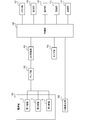
- FIG. 2 is a functional block diagram of the portable electrocardiographic device according to the embodiment.
- FIG. 3 is a functional block diagram of the smartphone according to the embodiment.
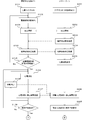
- FIG. 4 is a part of a flowchart for explaining the procedure of the electrocardiographic waveform measurement process of the portable electrocardiographic device according to the embodiment.
- FIG. 5 is a part of a flowchart for explaining the procedure of the electrocardiographic waveform measurement process of the portable electrocardiographic device according to the embodiment.
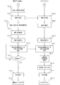
- FIG. 6 is a flowchart illustrating a procedure for electrocardiographic waveform analysis processing of the portable electrocardiographic device according to the embodiment.
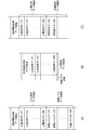
- FIG. 7 is a schematic diagram showing a data storage format in the portable electrocardiographic device according to the embodiment.
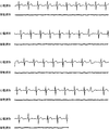
- FIG. 8 is a graph showing an electrocardiographic waveform and a body movement waveform when there is almost no body movement.
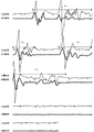
- FIG. 9 is a graph showing an electrocardiographic waveform and a body movement waveform when there is a large body movement during a part of the measurement period.
- FIG. 10 is a graph showing an electrocardiographic waveform and a body movement waveform when there is a large body movement over the entire measurement period.
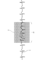
- FIG. 11 is a diagram showing a display example on a smartphone according to the embodiment.
- FIG. 1A is a front view of the portable electrocardiographic device 100.
- FIG. 1B is a view of the portable electrocardiographic device 100 as viewed from below.
- FIG. 1C is a view of the portable electrocardiographic device 100 as viewed from above.
- FIG. 1D is a diagram showing a left side surface of the portable electrocardiographic device 100 as viewed from the front surface.
- FIG. 1 (E) is a view showing a right side surface of the portable electrocardiographic device 100 as viewed from the front surface.
- FIG. 1F is a rear view of the portable electrocardiographic device 100.
- the vertical direction means the vertical direction on the paper surface with respect to the portable electrocardiographic device 100 in the posture shown in FIG. 1 (A).
- the main body 1 of the portable electrocardiographic device 100 has a substantially quadrangular prism shape with rounded corners, and the front and back surfaces are formed flat.
- a first electrode 2 is provided on the bottom of the portable electrocardiographic device 100.
- the upper part of the portable electrocardiographic device 100 is provided with a second electrode 3 on the left side and a third electrode 4 on the right side when viewed from the front surface.
- the upper part of the portable electrocardiographic device 100 has a shape that is smoothly curved so that the index finger of the subject's right hand can easily come into contact with the device.
- a measurement notification LED 5 and an abnormal wave detection LED 6 are arranged side by side on the front surface of the main body 1 of the portable electrocardiographic device 100.
- the measurement notification LED 5 is a light emitting element that lights up or blinks when measuring an electrocardiographic waveform.
- the abnormal waveform detection LED 6 is a light emitting element that lights up when an abnormal waveform is detected with respect to the measured electrocardiographic waveform. Through the lighting of the abnormal waveform detection LED 6, the subject is notified of the presence or absence of the abnormal waveform detected from the measurement data of the electrocardiographic waveform.
- a power switch 7, a power LED 8, a BLE communication button 9, a communication LED 10, a memory remaining display LED 11, and a battery replacement LED 12 are arranged side by side on the left side of the main body 1 of the portable electrocardiographic device 100 when viewed from the front. ing.
- the power switch 7 is a pressing switch for turning on the power of the portable electrocardiographic device 100
- the power LED 8 is a light emitting element that lights up when the power is turned on.
- the BLE communication button 9 is an operation component for functioning communication with a device compliant with the BLE (Bluetooth Low Energy) method
- the communication LED 10 is a light emitting element that lights up during communication.
- the communication function of the portable electrocardiographic device 100 is not limited to the BLE method, but is a wireless communication method such as infrared communication or information transmission by ultrasonic waves, or a wired communication method connected via a cable or a connector. May be good.
- the memory remaining display LED 11 is a light emitting element that indicates the state of the free capacity of the memory unit, which will be described later.
- the battery replacement LED 12 is a light emitting element that lights up when the power of the power source (battery) included in the portable electrocardiographic device 100 falls below a predetermined value to encourage battery replacement. Further, a removable battery cover 13 is provided on the back surface of the main body 1 of the portable electrocardiographic device 100.
- the first electrode 2 provided on the bottom of the main body is brought into contact with the left palm while holding the portable electrocardiographic device 100 with the right hand. ..
- the index finger of the right hand is brought into contact with the second electrode 3, and the middle node of the index finger of the right hand is brought into contact with the third electrode 4.
- the electrocardiogram is measured while pressing the first electrode 2 provided at the bottom in the direction of pressing the first electrode 2 provided at the bottom from the upper side of the main body provided with the second electrode 3 and the third electrode 4. Is done.
- the subject holds, for example, the portable electrocardiographic device 100 with his right hand and holds the first electrode 2 provided on the bottom of the main body on the left chest. Contact the skin slightly to the left of the epigastric region and below the nipple.
- the index finger of the right hand is brought into contact with the second electrode 3, and the middle node of the index finger of the right hand is brought into contact with the third electrode 4.
- the electrocardiographic measurement is performed while pressing the first electrode 2 provided at the bottom in the direction of pressing the first electrode 2 provided at the bottom from the upper side of the main body 1 provided with the second electrode 3 and the third electrode 4. .
- FIG. 2 is a diagram showing an example of a system configuration of the portable electrocardiographic device 100 according to the present embodiment.
- the portable electrocardiographic device 100 includes an electrode unit 101, an amplifier unit 102, an AD (Analog to Digital) conversion unit 103, a control unit 104, a timer unit 105, and a body motion detection unit 106. Consists of including. Further, the configuration of the portable electrocardiographic device 100 includes a memory unit 107, a display unit 108, an operation unit 109, a power supply unit 110, and a communication unit 111. The control unit 104, the timer unit 105, the body motion detection unit 106, the memory unit 107, the display unit 108, the operation unit 109, the power supply unit 110, and the communication unit 111 are connected to each other.
- AD Analog to Digital
- the electrode unit 101 includes a first electrode 2 and a third electrode 4 that function as a pair of measurement electrodes, and a second electrode 3 that functions as a GND electrode.
- An electrocardiographic waveform within a predetermined period is detected through the electrode portion 101 in contact with the skin of the subject.
- the electrocardiographic waveform detected at each electrode of the electrode unit 101 is input to the amplifier unit 102 connected to the electrode unit, respectively.
- the signal detected by the electrode unit 101 is amplified and output to the AD conversion unit 103.
- the detection signal of the electrocardiographic waveform amplified through the amplifier unit 102 is digitally converted and output to the control unit 104.
- the timer unit 105 is a means for receiving an instruction from the control unit 104 and counting various times or periods related to the measurement of the electrocardiographic waveform.
- the body movement detection unit 106 detects the magnitude of the body movement of the subject at the time of measuring the electrocardiographic waveform as the body movement level.
- an acceleration sensor, a microphone, or the like can be used as the body motion detection unit.
- the body motion detection unit 106 can be provided near the third electrode, for example, but the location of the body motion detection unit 106 is not limited to this.
- the memory unit 107 includes a main storage device such as a ROM (Read Only Memory) and a RAM (Random Access Memory), as well as a long-term storage medium such as a flash memory.
- the memory unit 107 stores various programs related to the measurement and analysis of body movement intensity and electrocardiographic waveform, various information for detecting abnormal waveforms, and the like.
- the display unit 108 is a means for displaying various information related to the measurement of the electrocardiographic waveform.
- the display unit 108 includes a measurement notification LED 5, an abnormal waveform detection LED 6, a power supply LED 8, a communication LED 10, a memory remaining display LED 11, and a battery replacement LED 12.
- the display unit 108 may include means for displaying various types of information by means of an image / video such as a liquid crystal display.
- the operation unit 109 is a means for receiving an operation input from the subject.
- the operation unit 109 includes a power switch 7 and a BLE communication button 9.
- the power supply unit 110 is a means for supplying electric power for operating the portable electrocardiographic device 100, and includes a battery, a secondary battery, and the like.
- the communication unit 111 is a communication interface that controls transmission and reception of signals with a device such as a smartphone 200. BLE communication can be exemplified as the communication function provided by the communication unit 111, but other known wireless communication methods and wired communication methods can be adopted.
- FIG. 3 is a block diagram showing the configuration of the smartphone 200.
- the smartphone 200 constitutes an electrocardiographic measurement system in cooperation with the portable electrocardiographic device 100.
- the smartphone 200 includes a control unit 201, a touch panel display 202, an audio output unit 203 such as a speaker, a memory unit 204, an audio input unit 205 such as a microphone, an operation unit 206 such as a button, a power supply unit 207, and a portable electrocardiographic device 100.
- It is configured to include a communication unit 208, which is a communication interface that controls transmission / reception of signals by a method such as BLE communication.
- a known configuration can be adopted for the smartphone 200, which is an example of a terminal capable of communicating with the portable electrocardiographic device 100, and thus will not be described in detail.
- Electrocardiographic measurement processing 4 and 5 are flowcharts illustrating a procedure for measuring an electrocardiographic waveform while performing BLE communication between a portable electrocardiographic device 100 and a terminal equipped with a BLE type communication function such as a smartphone 200.
- the power is turned on by pressing the power switch 7 of the portable electrocardiographic device 100 (step S101).
- the smartphone 200 opens an application program for electrocardiographic measurement (hereinafter, referred to as “application”) (step S201).
- application an application program for electrocardiographic measurement
- preparations for electrocardiographic measurement such as association between the portable electrocardiographic device 100 and the smartphone 200 in which the application for electrocardiographic measurement is installed, registration of the subject's ID, etc. have been completed. explain.
- the electrode contact state is detected (step S102). Specifically, when performing I-lead measurement with the portable electrocardiographic device 100, the fingerprint portion of the tip of the index finger of the right hand is brought into contact with the second electrode 3, and the middle node of the index finger of the right hand is brought into contact with the third electrode 4. Let me. Then, the left palm is brought into contact with the first electrode 2.
- the electric signal acquired via the electrodes 2, 3 and 4 is amplified by the amplifier unit 102 and digitally converted by the AD conversion unit to generate a contact state detection signal.
- the contact state detection signal generated in this way is transmitted to the control unit 104 to detect the contact state between the subject and each of the electrodes 2, 3 and 4.
- a BLE connection is made between the portable electrocardiographic device 100 and the smartphone 200 according to a predetermined procedure (step S103, step S202).
- the smartphone 200 transmits a communication start request to the portable electrocardiographic device 100 (step S203).
- the portable electrocardiographic device 100 Upon receiving the communication start request, the portable electrocardiographic device 100 transmits information indicating the electrode contact state to the smartphone 200 (step S104).
- the electrode contact state is displayed on the touch panel display 202 or the like, and the subject is notified that the electrodes 2, 3 and 4 are in normal contact.
- the control unit 104 determines whether or not the electrode contact state is maintained and a predetermined time has elapsed (step S105). If No is determined in step S105, the process returns to step S102. However, in this case, since the BLE connection has already been established, the processes of step S103 and steps S202 and S203 on the smartphone 200 side are omitted. If it is determined to be Yes in step S105, the control unit 104 starts the electrocardiographic measurement (step S106).
- the portable electrocardiographic device 100 When the electrocardiographic measurement is started, the portable electrocardiographic device 100 performs streaming communication with the smartphone 200 and transmits the electrocardiographic waveform information and the measurement time information to the smartphone 200 (step S107).
- the measurement time information is information regarding the elapsed time from the start of electrocardiographic measurement, which is counted by the timer unit 105, and here, the remaining measurement time obtained by subtracting the elapsed time from the start of electrocardiographic measurement from a predetermined time. This is information indicating.
- Information on the elapsed time from the start of electrocardiographic measurement may be transmitted from the portable electrocardiographic device 100 to the smartphone 200, and the smartphone 200 may perform subtraction processing from the predetermined time.
- the smartphone 200 receives the electrocardiographic waveform information and the measurement time information from the portable electrocardiographic device 100 (step S206), and displays the electrocardiographic waveform and the measurement time on the touch panel display 202 (step S207). As a result, the subject is notified that the electrocardiographic measurement is normally performed and the remaining measurement time.
- the body movement detection unit 106 detects the body movement of the subject in parallel (step S108).
- the subject changes his / her posture during the electrocardiographic measurement, or the middle finger in contact with the second electrode 3 and the third electrode 4 or the left palm in contact with the first electrode trembles or makes a voice.
- the body movement detection unit 106 the period during which the body movement occurs and the body movement level are detected in synchronization with the electrocardiographic waveform, and the predetermined memory unit 107 of the portable electrocardiographic device 100 is detected. Save to area.
- the electrocardiographic waveform is stored in the memory unit 107 in association with the timing at which the electrocardiographic waveform is detected, and the body movement level is also stored in the memory unit 107 in association with the timing at which the body movement level is detected.
- the shape and the body movements that occur at the same time are synchronized via the timing at which they are detected.
- the control unit 104 includes a message prompting the subject to take the correct measurement posture during the electrocardiographic measurement.
- the information is transmitted to the smartphone 200 (step S108).
- the smartphone 200 receives this information (step S206), displays a message prompting the subject to take the correct measurement posture during the electrocardiographic measurement on the touch panel display, or outputs a voice message from the voice output unit 203. (Step S207).
- the control unit 104 sets the measurement notification LED 12 or the abnormal wave detection LED 13 in a mode different from the measurement notification or the abnormal wave detection. By blinking, the subject may be urged to take the correct measurement posture.
- the portable electrocardiographic device 100 may be separately provided with an LED, a speaker, a vibrator, or the like to notify the subject that the body movement level is equal to or higher than a predetermined second threshold value.
- the measurement notification LED 12, the abnormal wave detection LED 13, a separately provided LED, a speaker, a vibrator, or the like corresponds to the notification unit of the present invention.
- Only the information instructing the touch panel display 202 to display a message prompting the subject to take the correct measurement posture during the electrocardiographic measurement is transmitted from the portable electrocardiographic device 100 to the smartphone 200, and the smartphone 200 receives the information.
- the information may be interpreted and a message may be displayed on the touch panel display 202.
- the control unit 104 determines whether or not a predetermined measurement time has elapsed with respect to the elapsed time from the start of the electrocardiographic measurement counted by the timer unit 105 (step S109). If No is determined in step S109, the process returns to step S106 and the electrocardiographic measurement is continued. If it is determined to be Yes in step S109, the control unit 104 analyzes the body movement and the electrocardiographic waveform (step S110).
- the control unit 104 determines whether or not the body movement level of the subject detected by the body movement detection unit 106 is equal to or higher than a predetermined first threshold value (step S1101). If it is determined to be Yes in step S1101, the control unit 104 saves information regarding the time when the body movement level equal to or higher than the first threshold value is detected (step S1102). If No is determined in step S1102, the control unit 104 saves the electrocardiographic waveform data measured in synchronization with the body movement whose body movement level is less than the first threshold value as the analysis target data (step). S1103).
- FIG. 7 schematically shows a format for storing electrocardiographic waveform data and information on body movement level in a predetermined area of the memory unit 107.
- FIG. 7A is an example in which the body movement level data is acquired at the same time as the electrocardiographic waveform data and stored in the electrocardiographic waveform data area and the body movement level area assigned to the memory unit 107 in order. ..
- the information regarding the date and time when the electrocardiographic measurement is started is similarly stored in the measurement start date and time data area assigned to the memory unit 107 in association with the electrocardiographic waveform data and the body movement level data.
- FIG. 7A is an example in which the body movement level data is acquired at the same time as the electrocardiographic waveform data and stored in the electrocardiographic waveform data area and the body movement level area assigned to the memory unit 107 in order. ..
- the information regarding the date and time when the electrocardiographic measurement is started is similarly stored in the measurement start date and time data area assigned to the memory unit 107 in association with the electrocardiographic wave
- body movement level data is acquired at the same time as the electrocardiographic waveform data, and the electrocardiographic waveform data and the body movement flag are set in the electrocardiographic waveform data area and the body movement flag area assigned to the memory unit 107, respectively.
- the body movement flag is, for example, "1" when the body movement level is equal to or higher than the first threshold value, and "0" when the body movement level is less than the first threshold value. Is.
- the body movement level since only the body movement flag is stored, the amount of data is reduced and the storage capacity of the memory unit 107 can be suppressed. In FIG.
- body movement level data is acquired at the same time as the electrocardiographic waveform data, and the electrocardiographic waveform data is sequentially stored in the electrocardiographic waveform data area of the memory unit 107.
- the time and duration of the occurrence of is saved as the body movement generation data in the body movement generation data area.
- the body movement generation data can be, for example, the time when the body movement level exceeds the first threshold value and the time until it becomes less than the first threshold value as the duration.
- the body movement level since only the body movement generation data is stored, the amount of data is reduced and the storage capacity of the memory unit 107 can be suppressed.
- the format in which the electrocardiographic waveform data and the body movement level data are stored in the memory unit 107 in association with the timing at which each is detected is not limited to the above.
- the control unit 104 determines whether or not the total of the periods during which the data whose body movement level is equal to or higher than the first threshold value is detected is equal to or longer than the predetermined time (step S1104).
- electrocardiographic measurement is performed by setting a fixed measurement time, if the proportion of the period during which the body movement level is equal to or higher than the first threshold value increases, the amount of electrocardiographic waveform data to be analyzed decreases. Accurate analysis will not be possible.
- the electrocardiographic measurement time is set with a margin, even if the electrocardiographic waveform data for a part of the period is lost, the analysis accuracy is not necessarily affected. Therefore, it is determined here whether or not the electrocardiographic waveform data to the extent that the accuracy of the analysis can be ensured is acquired.
- step S1104 determines that the analysis is not performed (analysis is not possible) (step S1105).
- the fact that this analysis is not performed may be transmitted to the smartphone 200 as an analysis result to prompt the subject to perform another electrocardiographic measurement.
- step S1104 the analysis is performed on the data stored as the analysis target, that is, the electrocardiographic waveform data measured in synchronization with the body movement whose body movement level is less than the threshold value. (Step S1106).
- a method for analyzing the electrocardiographic waveform various known methods can be adopted and will not be described in detail.
- FIGS. 8, 9, and 10th are graphs showing the electrocardiographic waveform and the body movement waveform combined.
- the thin solid line is the electrocardiographic waveform
- the thick solid line is the body movement waveform
- the dotted line with an arrow indicates the period during which the body movement level is equal to or higher than the predetermined first threshold value.
- FIGS. 8, 9, and 10 a synchronized electrocardiographic waveform and a body motion waveform are paired, and a state in which the time series progresses from the upper row to the lower row is displayed.
- FIG. 8 shows an example in which the body movement level of the electrocardiographic waveform does not fluctuate or is extremely small throughout the measurement time of the electrocardiographic waveform (for example, 30 seconds).
- the body movement level is equal to or higher than the first threshold value in the two periods Pr1 and Pr2.
- the body movement level is less than the first threshold value in the period before Pr1, the period between Pr1 and Pr2, and the period after Pr2.
- the electrocardiographic waveform data of the periods other than Pr1 and Pr2 for example, determining the presence or absence of atrial fibrillation (AF). can do.
- AF atrial fibrillation
- the period Pr3 in which the body movement level is equal to or higher than the threshold value covers the entire period of the electrocardiographic measurement time. In such a case, since the length of the period Pr3 is the predetermined time or more, it is determined that the analysis is impossible.
- the electrocardiographic waveform and the body movement waveform as shown in FIG. Will be measured, and normal electrocardiographic measurement will be performed.
- the control unit 104 transmits information indicating that the electrocardiographic waveform is being analyzed to the smartphone 200 during the analysis of the electrocardiographic waveform including the body movement (step S111).
- the smartphone 200 receives the information indicating that the electrocardiographic waveform is being analyzed from the portable electrocardiographic device 100 (step S208)
- the smartphone 200 displays the information indicating that the electrocardiographic waveform is being analyzed on the display (step S208). Step S209).
- the control unit 104 saves the body movement, the electrocardiographic waveform and the analysis result in a predetermined area of the memory unit 107 (step S112).
- the body movement, the electrocardiographic waveform, and the analysis result may not be stored in the memory unit 107 of the portable electrocardiographic device 100, but may be stored only in the smartphone 200 side. Further, only one of the body movement, the electrocardiographic waveform, and the analysis result may be stored in the memory unit 107 of the portable electrocardiographic device 100.
- the control unit 104 blinks the abnormal wave detection LED 13 to notify the subject of the abnormal wave detection (step S113).
- the control unit 104 transmits the analysis result to the smartphone 200 by high-speed data communication (step S114).
- the analysis result also includes the induction type at the time of electrocardiographic measurement.
- the smartphone 200 receives the analysis result transmitted from the portable electrocardiographic device 100 (step S210).
- the control unit 104 uses high-speed data communication to send these information to the smartphone in order from the newest one. Send to 200.
- the analysis result includes the induction type at the time of electrocardiographic measurement.
- the smartphone 200 receives the untransmitted electrocardiographic waveform data, body movement data, and analysis result from the portable electrocardiographic device 100 (step S211), and saves them in a predetermined area of the memory unit 204. Then, the smartphone 200 displays the latest electrocardiographic waveform and the analysis result on the display (step S212).
- the BLE is responded to the communication end request (step S213) transmitted from the smartphone 200.
- the communication is disconnected (step S117).
- the BLE communication is also disconnected on the smartphone 200 side (step S214).
- the power switch 7 is turned off in the portable electrocardiographic device 100 (step S118).
- the power switch 7 may be automatically turned off by the control unit 104 after a lapse of a predetermined time after the BLE is disconnected, or may be turned off by pressing the power switch 7 by the subject.
- the smartphone 200 closes the application after disconnecting the BLE communication (step S215). In this way, the electrocardiographic measurement in cooperation with the smartphone 200 in the portable electrocardiographic device 100 is completed.
- the electrocardiographic waveform data during the period is excluded from the analysis. There is. Therefore, since the analysis can be performed using the electrocardiographic waveform data with less noise, it is possible to perform the electrocardiographic waveform analysis with high accuracy.
- FIG. 11 shows an example of displaying the electrocardiographic waveform data on the touch panel display 202 of the smartphone 200 that has received the electrocardiographic waveform data and the body movement level data stored in the memory unit 107 of the portable electrocardiographic device 100.
- the color of the background 31 of the electrocardiographic waveform region 301 corresponding to a certain period of body movement (for example, a period in which the body movement level is equal to or higher than the first threshold value) is changed to no body movement. It is displayed in gray, which is different from the area.
- the display mode such as the display color of the electrocardiographic waveform itself and the line thickness corresponding to a certain period of body movement may be changed.
- the electrocardiographic waveform and the body movement level waveform may be superimposed or arranged so as to be displayed on the touch panel display 202.
- the display mode in which the timing at which the electrocardiographic waveform is detected and the timing at which the body movement level is detected is not limited to these.
- the body movement level is equal to or higher than the first threshold value at the time of analyzing the electrocardiographic waveform, and the period during which the body movement level is equal to or higher than the first threshold value is excluded from the analysis target. Occasionally, it may be determined whether or not the body movement level is equal to or higher than the first threshold value, and if the total of the periods during which the body movement level is equal to or higher than the first threshold value exceeds a predetermined time, the measurement time may be extended. Further, in the above-described embodiment, the first threshold value and the second threshold value are set for the body movement level, but the first threshold value and the second threshold value may be the same value or different values.
Landscapes
- Health & Medical Sciences (AREA)
- Life Sciences & Earth Sciences (AREA)
- Molecular Biology (AREA)
- Surgery (AREA)
- Biophysics (AREA)
- Pathology (AREA)
- Engineering & Computer Science (AREA)
- Biomedical Technology (AREA)
- Heart & Thoracic Surgery (AREA)
- Medical Informatics (AREA)
- Veterinary Medicine (AREA)
- Physics & Mathematics (AREA)
- Animal Behavior & Ethology (AREA)
- General Health & Medical Sciences (AREA)
- Public Health (AREA)
- Cardiology (AREA)
- Physiology (AREA)
- Dentistry (AREA)
- Oral & Maxillofacial Surgery (AREA)
- Measurement And Recording Of Electrical Phenomena And Electrical Characteristics Of The Living Body (AREA)
- Measurement Of The Respiration, Hearing Ability, Form, And Blood Characteristics Of Living Organisms (AREA)
Abstract
被検者の体動を考慮して精度よく心電波形解析を行う技術を提供する。被検者の心電波形を検出する電極部と、前記被検者の体動レベルを検出する体動検出部と、時間をカウントするタイマ部と、メモリ部と、制御部と、を備え、前記制御部は、前記体動レベル及び前記心電波形を、該体動レベルが検出されたタイミングと該心電波形が検出されたタイミングとを関連付けて、メモリ部に保存する。
Description
本発明は、日常生活等における心電波形測定が可能な携帯型の心電装置およびこれを含心電測定システムに関する。
日常生活における胸部の痛みや動悸などの異常発生時に、すぐに心電波形を測定可能な携帯型の心電測定装置(以下、「携帯型心電装置」ともいう)が提案されている。医師等においては、家庭や外出先等で動悸等の症状が起きた際に当該心電装置によって測定された心電波形のデータ等に基づいて、心疾患の早期発見や適切な治療行為を施すことが可能になる。
従来、生体情報を測定する装置に、加速度センサ等の振動を検出する手段を備えた装置が提案されている。特許文献1では、心電計に体動検出手段を設け、被検者の活動量と心電波形を関連付けて保存し解析している。ここでは、活動量として、ジョギング、歩行等が述べられている。また、特許文献2では、任意の期間でバイタルサインを繰り返し測定する際に、加速度センサで運動中を示す場合には、運動中のデータを無効化し、安定している期間のみデータを記録している。特許文献3では、表示部がない生体情報検出器が複数存在する場合に、それぞれの生体情報検出器に加速度センサを設け、情報を送信する生体情報検出器を振ることにより加速度が閾値を上回ったか否かを示すフラグ情報と生体情報を関連付けている。そして、加速度が閾値を上回った場合にデータを送信することにより、特定の生体情報検出器のデータ送信を可能としている。
生体情報を測定する装置では、被検者の症状を正確に把握するために、測定データの品質が特に重要である。とりわけ、携帯型心電装置では、標準的12誘導心電図検査のように安定した仰臥姿勢での測定を前提としないため、心電波形データの品質に影響を与える要因として、測定中における被検者の体動が重要である。
しかしながら、これまでの携帯型心電装置では、被検者が測定中に姿勢を変化させたり、体を震わせたり、声を出したりすると、心電波形に被検者の体動によるノイズが加わり、誤った解析結果が出力されることがあった。
上記のような従来の技術に鑑み、本発明は、被検者の体動を考慮して精度よく心電波形解析を行う技術を提供することを目的とする。
上記の課題を解決するため、本発明に係る携帯型心電装置は、
被検者の心電波形を検出する電極部と、
前記被検者の体動レベルを検出する体動検出部と、
時間をカウントするタイマ部と、
メモリ部と、
制御部と、
を備え、
前記制御部は、
前記体動レベル及び前記心電波形を、該体動レベルが検出されたタイミングと該心電波形が検出されたタイミングとを関連付けて、メモリ部に保存することを特徴とする。
被検者の心電波形を検出する電極部と、
前記被検者の体動レベルを検出する体動検出部と、
時間をカウントするタイマ部と、
メモリ部と、
制御部と、
を備え、
前記制御部は、
前記体動レベル及び前記心電波形を、該体動レベルが検出されたタイミングと該心電波形が検出されたタイミングとを関連付けて、メモリ部に保存することを特徴とする。
このようにすれば、心電波形を解析する際に、心電波形のみならず、同じタイミングでの体動レベルの情報がメモリ部に保存されるので、心電波形検出時の体動レベルの情報が提供される。心電波形と同期させた体動レベルの情報を提供することにより、被検者の体動を考慮して心電波形を精度よく解析することができる。
体動レベルは、例えば、体動検出部としての加速度センサによって検出される、被検者の体の動きの加速度の大きさや、これを積分して得られる速度、さらにこれを積分した変位(振幅)が含まれるが、これに限られない。
体動レベルは、例えば、体動検出部としての加速度センサによって検出される、被検者の体の動きの加速度の大きさや、これを積分して得られる速度、さらにこれを積分した変位(振幅)が含まれるが、これに限られない。
また、本発明において、
前記制御部は、
前記心電波形と、該心電波形が検出されたタイミングと同時に検出された前記体動レベルとに基づいて、該心電波形を解析するようにしてもよい。
前記制御部は、
前記心電波形と、該心電波形が検出されたタイミングと同時に検出された前記体動レベルとに基づいて、該心電波形を解析するようにしてもよい。
このようにすれば、心電波形の解析が、心電波形のみならず、これと同時に検出された、すなわち同期された体動レベルとに基づいて行われるので、精度よい解析が可能となる。
また、本発明において、
前記制御部は、
第1閾値以上である前記体動レベルが検出されたタイミングにおいて検出された前記心電波形を除いて、前記心電波形を解析するようにしてもよい。
前記制御部は、
第1閾値以上である前記体動レベルが検出されたタイミングにおいて検出された前記心電波形を除いて、前記心電波形を解析するようにしてもよい。
このようにすれば、心電波形解析の精度に影響を与える体動レベルとして第1閾値を設定し、第1閾値以上の体動レベルが検出されたタイミングにおいて検出された心電波形を、解析から除き、体動によるノイズが少ない心電波形を対象として解析を行うので、精度よい心電波形解析ができる。
また、本発明において、
前記制御部は、
前記第1閾値以上である前記体動レベルが検出された期間が所定時間以上である場合には、前記心電波形を解析しないようにしてもよい。
前記制御部は、
前記第1閾値以上である前記体動レベルが検出された期間が所定時間以上である場合には、前記心電波形を解析しないようにしてもよい。
解析に用いるデータ量に対して余裕を持たせて、心電波形の測定時間を一定時間に設定した場合に、測定時間の一部で体動レベルが第1閾値以上であっても、心電波形の精度を確保できるが、体動レベルが第1閾値以上となる期間の割合が高くなると心電波形解析の精度が低下する。このため、第1閾値以上である体動レベルが検出された期間が所定時間以上である場合には、心電波形を解析しないようにすることで、精度の低い解析結果を出力することがなく、解析に要する時間も省略できる。
また、本発明において、
前記被検者に情報を提供する報知部を備え、
前記制御部は、
第2閾値以上である前記体動レベルが検出された場合には、前記報知部によって、前記被検者の姿勢に関する情報を提供するようにしてもよい。
前記被検者に情報を提供する報知部を備え、
前記制御部は、
第2閾値以上である前記体動レベルが検出された場合には、前記報知部によって、前記被検者の姿勢に関する情報を提供するようにしてもよい。
このように、第2閾値以上である体動レベルが検出された場合に、報知部によって、被検者の姿勢に関する情報として、姿勢が適切でない旨のメッセージ、正しい姿勢に関する情報を報知することにより、被検者が姿勢を変更すれば、以後の測定中の体動によるノイズの発生が抑えられる。また、再測定時の正しい姿勢での測定を促すことができる。
また、本発明は、
前記携帯型心電装置と、
前記携帯型心電装置と通信可能な端末とを含む心電測定システムとして構成することができる。
前記携帯型心電装置と、
前記携帯型心電装置と通信可能な端末とを含む心電測定システムとして構成することができる。
このように、携帯型心電装置において、体動レベルを、該体動レベルが検出されたタイミングと関連付け、心電波形を、該心電波形が検出されたタイミングと関連付けて、メモリ部に保存するので、携帯型心電装置と通信可能な端末とを連携させることにより、被検者の体動を考慮して心電波形を精度よく解析することができる心電測定システムを提供することができる。
端末としては、スマートフォンやタブレット端末やノートPC等の携帯可能な端末に限らず、据置型のパーソナルコンピュータ等であってもよい。
端末としては、スマートフォンやタブレット端末やノートPC等の携帯可能な端末に限らず、据置型のパーソナルコンピュータ等であってもよい。
また、本発明において、
前記携帯型心電装置の前記メモリ部に保存された前記体動レベル及び前記心電波形を前記端末に送信し、
前記端末は、前記心電波形又は、前記心電波形及び前記体動レベルを、該心電波形が検出されたタイミングと、該体動レベルが検出されたタイミングとを関連付けて表示するようにしてもよい。
前記携帯型心電装置の前記メモリ部に保存された前記体動レベル及び前記心電波形を前記端末に送信し、
前記端末は、前記心電波形又は、前記心電波形及び前記体動レベルを、該心電波形が検出されたタイミングと、該体動レベルが検出されたタイミングとを関連付けて表示するようにしてもよい。
このように、携帯型心電装置のメモリ部に保存された体動レベル及び心電波形を端末に送信し、端末において、心電波形が検出されたタイミングと、体動レベルが検出されたタイミングとを関連付けて表示するようにすれば、心臓自体の異常に起因する心電波形の乱れと、体動に起因する心電波形の乱れを明確に区別することができる。このとき、体動レベルが検出されたタイミングと心電波形が検出されたタイミングとを関連付けて、心電波形のみを表示してもよいし、心電波形と体動レベルの両方を表示してもよい。
本発明によれば、被検者の体動を考慮して精度よく心電波形解析を行う技術を提供することができる。
以下、本発明の具体的な実施形態について図面に基づいて説明する。
<実施形態1>
以下に、本発明の実施形態の一例について説明する。但し、この実施形態に記載されている構成部品の寸法、材質、形状、その相対配置などは、特に記載がない限りは、この発明の範囲をそれらのみに限定する趣旨のものではない。
以下に、本発明の実施形態の一例について説明する。但し、この実施形態に記載されている構成部品の寸法、材質、形状、その相対配置などは、特に記載がない限りは、この発明の範囲をそれらのみに限定する趣旨のものではない。
(携帯型心電装置の構成)
図1(A)~(F)は本実施形態に係る携帯型心電装置100の構成の一例を示す図である。図1(A)は、携帯型心電装置100を前面から見た図である。図1(B)は、携帯型心電装置100を下方から見た図である。図1(C)は、携帯型心電装置100を上方から見た図である。図1(D)は、携帯型心電装置100の前面から見た左側面を示す図である。図1(E)は、携帯型心電装置100の前面から見た右側面を示す図である。図1(F)は、携帯型心電装置100を背面から見た図である。上下方向は、図1(A)に示す姿勢の携帯型心電装置100に対して、紙面上での上下方向を意味する。
図1(A)~(F)は本実施形態に係る携帯型心電装置100の構成の一例を示す図である。図1(A)は、携帯型心電装置100を前面から見た図である。図1(B)は、携帯型心電装置100を下方から見た図である。図1(C)は、携帯型心電装置100を上方から見た図である。図1(D)は、携帯型心電装置100の前面から見た左側面を示す図である。図1(E)は、携帯型心電装置100の前面から見た右側面を示す図である。図1(F)は、携帯型心電装置100を背面から見た図である。上下方向は、図1(A)に示す姿勢の携帯型心電装置100に対して、紙面上での上下方向を意味する。
図1(A)~(F)に示すように、携帯型心電装置100の本体1は、角を丸めた略四角柱形状であって前面及び背面間が扁平に形成されている。携帯型心電装置100の底部には、第1電極2が設けられている。携帯型心電装置100の上部には、前面から見て左側に第2電極3、同右側に第3電極4が設けられている。携帯型心電装置100の上部は、被検者の右手人差し指が当接しやすいように滑らかに湾曲する形状となっている。携帯型心電装置100の本体1の前面には、測定通知LED5と異常波検出LED6が上下に並んで配置されている。測定通知LED5は、心電波形の計測時に点灯あるいは明滅する発光素子である。異常波形検出LED6は、計測された心電波形に関し、異常波形が検出された際に点灯する発光素子である。異常波形検出LED6の点灯を通じて、心電波形の測定データから検出された異常波形の有無が被検者に通知される。携帯型心電装置100の本体1の、前面から見て左側面には、電源スイッチ7、電源LED8、BLE通信ボタン9、通信LED10、メモリ残表示LED11、電池交換LED12が上下に並んで配置されている。電源スイッチ7は、携帯型心電装置100の電源を投入するための押下スイッチであり、電源LED8は電源投入時に点灯する発光素子である。BLE通信ボタン9は、BLE(Bluetooth Low Energy)方式に準拠した機器との通信を機能させるための操作部品であり、通信LED10は、通信時に点灯する発光素子である。なお、携帯型心電装置100の備える通信機能は、BLE方式に限られず、赤外線通信、超音波による情報伝送などの無線通信方法、ケーブル又はコネクタ等を介して接続される有線通信方式であってもよい。メモリ残表示LED11は、後述するメモリ部の空き容量の状態を示す発光素子である。電池交換LED12は、携帯型心電装置100の備える電源(バッテリ)の電力が所定値を下回ったときに点灯し、電池交換を促す発光素子である。また、携帯型心電装置100の本体1の背面には、着脱可能な電池カバー13が設けられている。
ここで、心電測定において、例えば、I誘導測定が行われる場合には、携帯型心電装置100を右手で把持しつつ、本体の底部に設けられた第1電極2を左手掌に接触させる。携帯型心電装置100を把持する際には、右手の人差し指を第2電極3に接触させ、右手人差し指の中節を第3電極4に接触させる。被検者では、例えば、第2電極3、第3電極4が設けられた本体の上部側から、底部に設けられた第1電極2を左手掌方向に押し当てる方向に押圧しながら心電測定が行われる。
また、心電測定においてV4誘導測定が行われる場合では、被検者は、例えば、携帯型心電装置100を右手で把持しつつ、本体の底部に設けられた第1電極2を、左胸部の心窩部やや左方・乳頭下方の皮膚に接触させる。携帯型心電装置100を把持する際には、右手の人差し指を第2電極3に接触させ、右手人差し指の中節を第3電極4に接触させる。そして、第2電極3、第3電極4が設けられた本体1の上部側から、底部に設けられた第1電極2を、測定部位方向に押し当てる方向に押圧しながら心電測定が行われる。
(携帯型心電装置の構成)
次に、携帯型心電装置100の構成を説明する。図2は、本実施形態に係る携帯型心電装置100のシステム構成の一例を示す図である。
次に、携帯型心電装置100の構成を説明する。図2は、本実施形態に係る携帯型心電装置100のシステム構成の一例を示す図である。
図2に示すように、携帯型心電装置100は、電極部101と、アンプ部102と、AD(Analog to Digital)変換部103と、制御部104と、タイマ部105、体動検出部106を含んで構成される。また、携帯型心電装置100の構成には、メモリ部107と、表示部108と、操作部109と、電源部110と、通信部111が含まれる。制御部104と、タイマ部105と、体動検出部106、メモリ部107と、表示部108と、操作部109と、電源部110と、通信部111とは相互に接続されている。
電極部101は、一対の測定電極として機能する第1電極2及び第3電極4と、GND電極として機能する第2電極3を備える。被検者の皮膚に接触された電極部101を通じて、所定期間内における心電波形が検出される。電極部101の各電極で検出された心電波形は、それぞれ、当該電極部に接続されるアンプ部102に入力される。アンプ部102では、電極部101で検出された信号が増幅されてAD変換部103に出力される。AD変換部103では、アンプ部102を通じて増幅された心電波形の検出信号がデジタル変換されて制御部104に出力される。
タイマ部105は、制御部104からの指示を受け付け、心電波形の計測に係る各種時間又は期間をカウントする手段である。体動検出部106は、心電波形測定時の被検者の体動の大きさを体動レベルとして検出する。体動検出部としては、加速度センサやマイクロフォン等を用いることができる。体動検出部106は、例えば、第3電極の近傍に設けることができるが、体動検出部106の設置場所はこれに限られない。
メモリ部107は、ROM(Read Only Memory)及びRAM(Random Access Memory)などの主記憶装置の他、例えばフラッシュメモリなどの長期記憶媒体を含んで構成される。メモリ部107には、体動の強度や心電波形の測定及び解析に係る各種プログラム、異常波形等を検出するための各種の情報が記憶される。表示部108は、心電波形の計測に係る各種の情報を表示する手段である。表示部108には、測定通知LED5、異常波形検出LED6電源LED8、通信LED10、メモリ残表示LED11、電池交換LED12が含まれる。表示部108は、液晶ディスプレイ等の画像・映像により各種の情報を表示する手段を含んでもよい。
操作部109は、被検者からの操作入力を受け付ける手段である。操作部109には、電源スイッチ7、BLE通信ボタン9が含まれる。電源部110は、携帯型心電装置100を機能させるための電力を供給する手段であり、バッテリや2次電池等が含まれる。通信部111は、スマートフォン200といった機器との間で信号の送受信を司る通信インターフェィスである。通信部111の提供する通信機能としてBLE通信が例示できるが、他の公知の無線通信方式、有線通信方式が採用できる。
(スマートフォン)
図3は、スマートフォン200の構成を示すブロック図である。後述するように、スマートフォン200は、携帯型心電装置100と連携して心電測定システムを構成する。
スマートフォン200は、制御部201と、タッチパネルディスプレイ202、スピーカ等の音声出力部203、メモリ部204、マイク等の音声入力部205、ボタン等の操作部206、電源部207、携帯型心電装置100との間でBLE通信等の方式による信号の送受信を司る通信インターフェースである通信部208を含んで構成される。携帯型心電装置100と通信可能な端末の一例であるスマートフォン200としては公知の構成を採用することができるので、詳述しない。
図3は、スマートフォン200の構成を示すブロック図である。後述するように、スマートフォン200は、携帯型心電装置100と連携して心電測定システムを構成する。
スマートフォン200は、制御部201と、タッチパネルディスプレイ202、スピーカ等の音声出力部203、メモリ部204、マイク等の音声入力部205、ボタン等の操作部206、電源部207、携帯型心電装置100との間でBLE通信等の方式による信号の送受信を司る通信インターフェースである通信部208を含んで構成される。携帯型心電装置100と通信可能な端末の一例であるスマートフォン200としては公知の構成を採用することができるので、詳述しない。
(心電測定処理)
図4及び図5、携帯型心電装置100と、スマートフォン200等のBLE方式の通信機能を搭載した端末とがBLE通信しながら心電波形を測定する手順を説明するフローチャートである。
図4及び図5、携帯型心電装置100と、スマートフォン200等のBLE方式の通信機能を搭載した端末とがBLE通信しながら心電波形を測定する手順を説明するフローチャートである。
まず、携帯型心電装置100の電源スイッチ7を押下することにより電源をONする(ステップS101)。一方、スマートフォン200では、心電測定用のアプリケーションプログラム(以下、「アプリ」という。)を開く(ステップS201)。ここでは、携帯型心電装置100と、心電測定用のアプリがインストールされたスマートフォン200との関連付け、被検者のIDの登録等の心電測定のための準備は完了しているものとして説明する。
携帯型心電装置100では、電極接触状態が検出される(ステップS102)。
具体的には、携帯型心電装置100によりI誘導測定を行う場合には、第2電極3に右手の人差し指の先端の指紋部を接触させ、第3電極4に右手人差し指の中節を接触させる。そして、第1電極2に左手掌を接触させる。各電極2、3、4を介して取得された電気信号をアンプ部102で増幅し、AD変換部でデジタル変換し、接触状態検出信号を生成する。このようにして生成された接触状態検出信号を制御部104に送信し、被検者と各電極2、3、4との接触状態を検出する。
具体的には、携帯型心電装置100によりI誘導測定を行う場合には、第2電極3に右手の人差し指の先端の指紋部を接触させ、第3電極4に右手人差し指の中節を接触させる。そして、第1電極2に左手掌を接触させる。各電極2、3、4を介して取得された電気信号をアンプ部102で増幅し、AD変換部でデジタル変換し、接触状態検出信号を生成する。このようにして生成された接触状態検出信号を制御部104に送信し、被検者と各電極2、3、4との接触状態を検出する。
次に、携帯型心電装置100とスマートフォン200との間で、所定の手順に従ってBLE接続を行う(ステップS103、ステップS202)。
携帯型心電装置100とスマートフォン200との間で、BLE接続が確立されると、スマートフォン200は携帯型心電装置100に対して、通信開始要求を送信する(ステップS203)。
通信開始要求を受信した携帯型心電装置100では、電極接触状態を示す情報を、スマートフォン200に送信する(ステップS104)。電極接触状態を示す情報を受信したスマートフォン200では、電極接触状態をタッチパネルディスプレイ202等に表示し、各電極2、3、4に正常に接触していることを被検者に知らせる。
携帯型心電装置100とスマートフォン200との間で、BLE接続が確立されると、スマートフォン200は携帯型心電装置100に対して、通信開始要求を送信する(ステップS203)。
通信開始要求を受信した携帯型心電装置100では、電極接触状態を示す情報を、スマートフォン200に送信する(ステップS104)。電極接触状態を示す情報を受信したスマートフォン200では、電極接触状態をタッチパネルディスプレイ202等に表示し、各電極2、3、4に正常に接触していることを被検者に知らせる。
制御部104は、電極接触状態が維持されて所定時間が経過されたか否かを判断する(ステップS105)。
ステップS105において、Noと判断された場合には、ステップS102に戻る。但し、この場合には、既に、BLE接続が確立されているので、ステップS103と、スマートフォン200側のステップS202及びS203の処理は省略される。
ステップS105において、Yesと判断された場合には、制御部104は心電測定を開始する(ステップS106)。
ステップS105において、Noと判断された場合には、ステップS102に戻る。但し、この場合には、既に、BLE接続が確立されているので、ステップS103と、スマートフォン200側のステップS202及びS203の処理は省略される。
ステップS105において、Yesと判断された場合には、制御部104は心電測定を開始する(ステップS106)。
心電測定が開始されると、携帯型心電装置100はスマートフォン200との間でストリーミング通信を行い、心電波形情報と測定時間情報をスマートフォン200に送信する(ステップS107)。測定時間情報は、タイマ部105でカウントされている、心電測定開始からの経過時間に関する情報であり、ここでは、心電測定開始からの経過時間を、所定時間から減算した、残りの測定時間を示す情報である。携帯型心電装置100から心電測定開始からの経過時間の情報をスマートフォン200に送信し、スマートフォン200側で所定時間からの減算処理を行ってもよい。一方、スマートフォン200では、携帯型心電装置100から心電波形情報と測定時間情報を受信し(ステップS206)、タッチパネルディスプレイ202に心電波形及び測定時間を表示する(ステップS207)。これにより、心電測定が正常に行われていることと、残りの測定時間が被検者に報知される。
携帯型心電装置100では、心電測定を開始すると、並行して体動検出部106により、被検者の体動を検出する(ステップS108)。被検者が心電測定中に姿勢を変えたり、第2電極3及び第3電極4に接触させている中指や第1電極に接触させている左手掌が震えたり、声を出したりして、体動検出部106によって体動が検出された場合には、心電波形と同期して体動が生じた期間と体動レベルを検出し、携帯型心電装置100のメモリ部107の所定領域に保存する。すなわち、心電波形は、心電波形が検出されたタイミングと関連付けてメモリ部107に保存され、体動レベルも、体動レベルが検出されたタイミングと関連付けてメモリ部107に保存され、心電波形と、同時に生じた体動とが、それぞれが検出されたタイミングを介して同期される。
体動検出部106によって検出された体動レベルが所定の第2閾値以上である場合には、制御部104は、心電測定中に被検者に正しい測定姿勢をとるように促すメッセージを含む情報をスマートフォン200に送信する(ステップS108)。スマートフォン200は、この情報を受信し(ステップS206)、心電測定中に被検者に正しい測定姿勢をとるように促すメッセージをタッチパネルディスプレイに表示し、又は音声出力部203から音声メッセージを出力する(ステップS207)。体動検出部106によって検出された体動レベルが所定の第2閾値以上である場合には、制御部104は、測定通知LED12又は異常波検出LED13を測定通知又は異常波検出とは異なるモードで点滅させることにより、被検者に正しい測定姿勢をとるように促すようにしてもよい。また、別途、携帯型心電装置100に、LED、スピーカ又はバイブレータ等を設けて、体動レベルが所定の第2閾値以上であることを被検者に報知するようにしてもよい。ここでは、測定通知LED12又は異常波検出LED13、別途設けられるLED、スピーカ又はバイブレータ等が本発明の報知部に対応する。携帯型心電装置100から、心電測定中に被検者に正しい測定姿勢をとるように促すメッセージをタッチパネルディスプレイ202に表示するよう指示する情報のみをスマートフォン200に送信し、スマートフォン200が受信した情報を解釈し、タッチパネルディスプレイ202にメッセージを表示するようにしてもよい。
体動検出部106によって検出された体動レベルが所定の第2閾値以上である場合には、制御部104は、心電測定中に被検者に正しい測定姿勢をとるように促すメッセージを含む情報をスマートフォン200に送信する(ステップS108)。スマートフォン200は、この情報を受信し(ステップS206)、心電測定中に被検者に正しい測定姿勢をとるように促すメッセージをタッチパネルディスプレイに表示し、又は音声出力部203から音声メッセージを出力する(ステップS207)。体動検出部106によって検出された体動レベルが所定の第2閾値以上である場合には、制御部104は、測定通知LED12又は異常波検出LED13を測定通知又は異常波検出とは異なるモードで点滅させることにより、被検者に正しい測定姿勢をとるように促すようにしてもよい。また、別途、携帯型心電装置100に、LED、スピーカ又はバイブレータ等を設けて、体動レベルが所定の第2閾値以上であることを被検者に報知するようにしてもよい。ここでは、測定通知LED12又は異常波検出LED13、別途設けられるLED、スピーカ又はバイブレータ等が本発明の報知部に対応する。携帯型心電装置100から、心電測定中に被検者に正しい測定姿勢をとるように促すメッセージをタッチパネルディスプレイ202に表示するよう指示する情報のみをスマートフォン200に送信し、スマートフォン200が受信した情報を解釈し、タッチパネルディスプレイ202にメッセージを表示するようにしてもよい。
制御部104は、タイマ部105でカウントされている心電測定開始からの経過時間について、所定の測定時間が経過したか否かを判断する(ステップS109)。
ステップS109において、Noと判断された場合には、ステップS106に戻り、心電測定を継続する。
ステップS109においてYesと判断された場合には、制御部104は、体動及び心電波形の解析を行う(ステップS110)。
ステップS109において、Noと判断された場合には、ステップS106に戻り、心電測定を継続する。
ステップS109においてYesと判断された場合には、制御部104は、体動及び心電波形の解析を行う(ステップS110)。
(体動及び心電波形解析処理)
以下に、図6を参照して、ステップS110の体動及び心電波形の解析処理について説明する。
まず、制御部104は、体動検出部106によって検出された被検者の体動レベルが所定の第1閾値以上であるか否かを判断する(ステップS1101)。
ステップS1101において、Yesと判断された場合には、制御部104は、第1閾値以上となる体動レベルが検出された時間に関する情報を保存する(ステップS1102)。
ステップS1102において、Noと判断された場合には、制御部104は、体動レベルが第1閾値未満である体動と同期して測定された心電波形データを解析対象データとして保存する(ステップS1103)。
以下に、図6を参照して、ステップS110の体動及び心電波形の解析処理について説明する。
まず、制御部104は、体動検出部106によって検出された被検者の体動レベルが所定の第1閾値以上であるか否かを判断する(ステップS1101)。
ステップS1101において、Yesと判断された場合には、制御部104は、第1閾値以上となる体動レベルが検出された時間に関する情報を保存する(ステップS1102)。
ステップS1102において、Noと判断された場合には、制御部104は、体動レベルが第1閾値未満である体動と同期して測定された心電波形データを解析対象データとして保存する(ステップS1103)。
図7に、メモリ部107の所定領域に、心電波形データ及び体動レベルに関する情報を保存する形式を模式的に示す。
図7(A)は、心電波形データと同時に体動レベルデータを取得し、メモリ部107に割り当てられた心電波形データ領域と体動レベル領域に、それぞれ順番に保存する場合の例である。このとき、心電測定を開始した日時に関する情報は、同様にメモリ部107に割り当てられた測定開始日時データ領域に、心電波形データ及び体動レベルデータと関連付けて保存される。
図7(B)は、心電波形データと同時に体動レベルデータを取得し、メモリ部107に割り当てられた心電波形データ領域と体動フラグ領域に、それぞれ心電波形データと体動フラグを保存する例である。ここで、体動フラグは、例えば、体動レベルが第1閾値以上である場合に「1」、体動レベルが第1閾値未満である場合に、「0」とする、体動レベルに関するデータである。体動レベルに関しては、体動フラグのみが保存されるので、データ量が少なくなり、メモリ部107の記憶容量を抑えることができる。
図7(C)は、心電波形データと同時に体動レベルデータを取得し、心電波形データはメモリ部107の心電波形データ領域に順番に保存するが、体動レベルについては、体動の発生時刻と継続時間を体動発生データとして、体動発生データ領域に保存する。体動発生データは、例えば、体動レベルが第1閾値を超えた時刻を発生時し、第1閾値未満となるまでの時間を継続時間とすることができる。体動レベルに関しては、体動発生データのみが保存されるので、データ量が少なくなり、メモリ部107の記憶容量を抑えることができる。
心電波形データと体動レベルデータを、それぞれが検出されたタイミングと関連付けてメモリ部107に保存する形式は上述のものに限られない。
図7(A)は、心電波形データと同時に体動レベルデータを取得し、メモリ部107に割り当てられた心電波形データ領域と体動レベル領域に、それぞれ順番に保存する場合の例である。このとき、心電測定を開始した日時に関する情報は、同様にメモリ部107に割り当てられた測定開始日時データ領域に、心電波形データ及び体動レベルデータと関連付けて保存される。
図7(B)は、心電波形データと同時に体動レベルデータを取得し、メモリ部107に割り当てられた心電波形データ領域と体動フラグ領域に、それぞれ心電波形データと体動フラグを保存する例である。ここで、体動フラグは、例えば、体動レベルが第1閾値以上である場合に「1」、体動レベルが第1閾値未満である場合に、「0」とする、体動レベルに関するデータである。体動レベルに関しては、体動フラグのみが保存されるので、データ量が少なくなり、メモリ部107の記憶容量を抑えることができる。
図7(C)は、心電波形データと同時に体動レベルデータを取得し、心電波形データはメモリ部107の心電波形データ領域に順番に保存するが、体動レベルについては、体動の発生時刻と継続時間を体動発生データとして、体動発生データ領域に保存する。体動発生データは、例えば、体動レベルが第1閾値を超えた時刻を発生時し、第1閾値未満となるまでの時間を継続時間とすることができる。体動レベルに関しては、体動発生データのみが保存されるので、データ量が少なくなり、メモリ部107の記憶容量を抑えることができる。
心電波形データと体動レベルデータを、それぞれが検出されたタイミングと関連付けてメモリ部107に保存する形式は上述のものに限られない。
次に、制御部104は、体動レベルが第1閾値以上であるデータが検出された期間の合計が所定時間以上であるか否かを判断する(ステップS1104)。一定の測定時間を設定して心電測定を行う場合に、体動レベルが第1閾値以上となる期間が占める割合が高くなると、解析の対象とされる心電波形のデータ量が少なくなり、精度のよい解析ができなくなってしまう。一方で、心電の測定時間に余裕を持たせて設定しておけば、一部の期間の心電波形のデータが欠落しても、必ずしも解析精度に影響を与えない。このため、解析の精度を確保できる程度の心電波形データが取得されているか否かを、ここで判断している。
ステップS1104において、Yesと判断された場合には、制御部104は、解析しない(解析不可)と判断する(ステップS1105)。この解析しない旨は、解析結果として、スマートフォン200に送信し、被検者に再度の心電測定を促すようにしてもよい。
ステップS1104において、Noと判断された場合には、解析対象として保存されたデータ、すなわち、体動レベルが閾値未満である体動と同期して測定された心電波形データを対象として解析を行う(ステップS1106)。心電波形の解析方法としては、公知の種々の方法を採用することができるので詳述しない。
ステップS1104において、Noと判断された場合には、解析対象として保存されたデータ、すなわち、体動レベルが閾値未満である体動と同期して測定された心電波形データを対象として解析を行う(ステップS1106)。心電波形の解析方法としては、公知の種々の方法を採用することができるので詳述しない。
図8、図9、図10に心電波形と体動波形を合せて表示したグラフを示す。細実線が心電波形、太実線が体動波形であり、矢印を付した点線が、体動レベルが所定の第1閾値以上である期間を示す。図8、図9、図10のいずれも、同期した心電波形と体動波形とを対として、上段から下段へと時系列が進む様子を表示している。
図8は、心電波形の測定時間(例えば30秒間)を通じて、心電波形の体動レベルの変動がない又は極めて小さい例を示す。このような場合は、体動レベルが第1閾値以上となる期間がなく、測定時間の全期間に亘る心電波形が解析対象データとなる。
図9の例では、期間Pr1及びPr2の二つの期間において、体動レベルが第1閾値以上となっている。一方で、測定期間のうち、Pr1より前の期間、Pr1とPr2に挟まれた期間、Pr2よりも後の期間では、いずれも体動レベルが第1閾値未満となっている。この場合には、期間Pr1及びPr2の合計が所定時間未満であるため、Pr1及びPr2以外の期間の心電波形データを解析することが可能になり、例えば心房細動(AF)の有無を判定することができる。
図10の例では、体動レベルが閾値以上である期間Pr3が、心電測定時間の全期間に亘っている。このような場合には、期間Pr3の長さが所定時間以上であるため、解析不可と判断される。スマートフォン200のタッチパネルディスプレイ202に正しい姿勢を表示する等して、被検者に再測定を促して、体動がない又は極めて小さい場合には、図8に示すような心電波形及び体動波形が測定されることとなり、正常な心電測定が行われる。
図8は、心電波形の測定時間(例えば30秒間)を通じて、心電波形の体動レベルの変動がない又は極めて小さい例を示す。このような場合は、体動レベルが第1閾値以上となる期間がなく、測定時間の全期間に亘る心電波形が解析対象データとなる。
図9の例では、期間Pr1及びPr2の二つの期間において、体動レベルが第1閾値以上となっている。一方で、測定期間のうち、Pr1より前の期間、Pr1とPr2に挟まれた期間、Pr2よりも後の期間では、いずれも体動レベルが第1閾値未満となっている。この場合には、期間Pr1及びPr2の合計が所定時間未満であるため、Pr1及びPr2以外の期間の心電波形データを解析することが可能になり、例えば心房細動(AF)の有無を判定することができる。
図10の例では、体動レベルが閾値以上である期間Pr3が、心電測定時間の全期間に亘っている。このような場合には、期間Pr3の長さが所定時間以上であるため、解析不可と判断される。スマートフォン200のタッチパネルディスプレイ202に正しい姿勢を表示する等して、被検者に再測定を促して、体動がない又は極めて小さい場合には、図8に示すような心電波形及び体動波形が測定されることとなり、正常な心電測定が行われる。
図5のフローチャートに戻って説明を続ける。
制御部104は、体動を含めた心電波形の解析中に、スマートフォン200に対して、心電波形の解析中であることを示す情報を送信する(ステップS111)。スマートフォン200は、携帯型心電装置100から、心電波形の解析中であることを示す情報を受信すると(ステップS208)、心電波形の解析中であることを示す情報をディスプレイに表示する(ステップS209)。
制御部104は、体動を含めた心電波形の解析中に、スマートフォン200に対して、心電波形の解析中であることを示す情報を送信する(ステップS111)。スマートフォン200は、携帯型心電装置100から、心電波形の解析中であることを示す情報を受信すると(ステップS208)、心電波形の解析中であることを示す情報をディスプレイに表示する(ステップS209)。
体動及び心電波形の解析が終了すると、制御部104は、体動、心電波形及び解析結果をメモリ部107の所定領域に保存する(ステップS112)。体動、心電波形及び解析結果を保存することなく、携帯型心電装置100のメモリ部107に保存せずに、スマートフォン200側にのみ保存するようにしてもよい。また、体動、心電波形及び解析結果のいずれかのみを携帯型心電装置100のメモリ部107に保存するようにしてもよい。
心電波形の解析により、異常波が検出された場合には、制御部104は、異常波検出LED13を点滅させて、被検者に異常波検出を報知する(ステップS113)。
心電波形の解析により、異常波が検出された場合には、制御部104は、異常波検出LED13を点滅させて、被検者に異常波検出を報知する(ステップS113)。
また、体動及び心電波形の解析が終了すると、制御部104は、高速のデータ通信により解析結果をスマートフォン200に送信する(ステップS114)。解析結果には、心電測定の際の誘導種別も含まれる。このとき、スマートフォン200では、携帯型心電装置100から送信された解析結果を受信する(ステップS210)。
そして、携帯型心電装置100に未送信の心電波形データ、体動データ、解析結果がある場合には、制御部104は、高速のデータ通信により、これらの情報を、新しいものから順にスマートフォン200に送信する。ここでも、解析結果には、心電測定の際の誘導種別が含まれる。このとき、スマートフォン200では、未送信の心電波形データ、体動データ、解析結果を携帯型心電装置100から受信し(ステップS211)、メモリ部204の所定領域に保存する。そして、スマートフォン200では、最新の心電波形と解析結果をディスプレイに表示する(ステップS212)。
携帯型心電装置100において、未送信の心電波形データ、体動データ、解析結果の送信が完了すると(ステップS116)、スマートフォン200から送信される通信終了要求(ステップS213)に応じて、BLE通信を切断する(ステップS117)。携帯型心電装置100におけるBLE通信の切断に対応して、スマートフォン200側でもBLE通信が切断される(ステップS214)。
BLE通信を切断した後に、携帯型心電装置100では、電源スイッチ7がOFFされる(ステップS118)。電源スイッチ7は、BLE切断後、所定の時間の経過により制御部104が自動的にOFFにしてもよいし、被検者による電源スイッチ7の押下によるOFFにしてもよい。一方、スマートフォン200では、BLE通信を切断した後に、アプリを閉じる(ステップS215)。このようにして、携帯型心電装置100におけるスマートフォン200と連携した心電測定が終了する。
このように、体動検出部106によって検出された体動レベルが所定の第1閾値以上である場合には、心電波形を解析する際に、当該期間の心電波形データを解析から除いている。このため、ノイズが少ない心電波形データにより解析を行うことができるので、精度のよい心電波形解析が可能となる。
また、携帯型心電装置100のメモリ部107に保存された心電波形データと体動レベルデータを受信したスマートフォン200のタッチパネルディスプレイ202における心電波形データの表示例を図11に示す。ここでは、心電波形30のうち、体動がある期間(例えば、体動レベルが第1閾値以上である期間)に対応する心電波形の領域301の背景31の色を、体動のない領域とは異なる灰色で表示している。このように、心電波形のうち、体動がある領域の背景色を変更して、タッチパネルディスプレイに表示することにより、心臓自体に異常がある場合の心電波形の乱れと、体動に起因する心電波形の乱れを明確に区別することができる。また、背景色ではなく、体動がある期間に対応する心電波形自体の表示色や線の太さ等の表示態様を変更するようにしてもよい。また、心電波形と体動レベルの波形を重ね合わせたり、並べたりして、タッチパネルディスプレイ202に表示するようにしてもよい。
心電波形が検出されたタイミングと、体動レベルが検出されたタイミングとを関連付けた表示態様はこれらに限られない。
心電波形が検出されたタイミングと、体動レベルが検出されたタイミングとを関連付けた表示態様はこれらに限られない。
(変形例)
上述の実施形態では、心電波形の解析時に体動レベルが第1閾値以上であるか否かを判断し、第1閾値以上である期間については解析の対象から除いているが、心電測定時に体動レベルが第1閾値以上か否かを判断し、第1閾値以上となる期間の合計が所定時間を超える場合には、測定時間を延長するようにしてもよい。
また、上述の実施形態では、体動レベルについて第1閾値と第2閾値を設定しているが、第1閾値と第2閾値とは同じ値でもよいし、異なる値であってもよい。
上述の実施形態では、心電波形の解析時に体動レベルが第1閾値以上であるか否かを判断し、第1閾値以上である期間については解析の対象から除いているが、心電測定時に体動レベルが第1閾値以上か否かを判断し、第1閾値以上となる期間の合計が所定時間を超える場合には、測定時間を延長するようにしてもよい。
また、上述の実施形態では、体動レベルについて第1閾値と第2閾値を設定しているが、第1閾値と第2閾値とは同じ値でもよいし、異なる値であってもよい。
1・・・携帯型心電装置
2・・・第1電極
3・・・第2電極
4・・・第3電極
101・・・電極部
104・・・制御部
106・・・体動検出部
2・・・第1電極
3・・・第2電極
4・・・第3電極
101・・・電極部
104・・・制御部
106・・・体動検出部
Claims (7)
- 被検者の心電波形を検出する電極部と、
前記被検者の体動レベルを検出する体動検出部と、
時間をカウントするタイマ部と、
メモリ部と、
制御部と、
を備え、
前記制御部は、
前記体動レベル及び前記心電波形を、該体動レベルが検出されたタイミングと該心電波形が検出されたタイミングとを関連付けて、メモリ部に保存することを特徴とする携帯型心電装置。 - 前記制御部は、
前記心電波形と、該心電波形が検出されたタイミングと同時に検出された前記体動レベルとに基づいて、該心電波形を解析することを特徴とする請求項1に記載の携帯型心電装置。 - 前記制御部は、
第1閾値以上である前記体動レベルが検出されたタイミングにおいて検出された前記心電波形を除いて、前記心電波形を解析することを特徴とする請求項2に記載の携帯型心電装置。 - 前記制御部は、
前記第1閾値以上である前記体動レベルが検出された期間が所定時間以上である場合には、前記心電波形を解析しないことを特徴とする請求項3に記載の携帯型心電装置。 - 前記被検者に情報を提供する報知部を備え、
前記制御部は、
第2閾値以上である前記体動レベルが検出された場合には、前記報知部によって、前記被検者の姿勢に関する情報を提供することを特徴とする請求項1乃至4のいずれか1項に記載の携帯型心電装置。 - 請求項1乃至5のいずれか1項に記載の携帯型心電装置と、
前記携帯型心電装置と通信可能な端末とを含む心電測定システム。 - 前記携帯型心電装置の前記メモリ部に保存された前記体動レベル及び前記心電波形を前記端末に送信し、
前記端末は、前記心電波形又は、前記心電波形及び前記体動レベルを、該心電波形が検出されたタイミングと、該体動レベルが検出されたタイミングとを関連付けて表示する請求項6に記載の心電測定システム。
Applications Claiming Priority (2)
| Application Number | Priority Date | Filing Date | Title |
|---|---|---|---|
| JP2020042834A JP7484250B2 (ja) | 2020-03-12 | 2020-03-12 | 携帯型心電装置及び心電測定システム |
| JP2020-042834 | 2020-03-12 |
Publications (1)
| Publication Number | Publication Date |
|---|---|
| WO2021182446A1 true WO2021182446A1 (ja) | 2021-09-16 |
Family
ID=77670585
Family Applications (1)
| Application Number | Title | Priority Date | Filing Date |
|---|---|---|---|
| PCT/JP2021/009212 Ceased WO2021182446A1 (ja) | 2020-03-12 | 2021-03-09 | 携帯型心電装置及び心電測定システム |
Country Status (2)
| Country | Link |
|---|---|
| JP (1) | JP7484250B2 (ja) |
| WO (1) | WO2021182446A1 (ja) |
Cited By (1)
| Publication number | Priority date | Publication date | Assignee | Title |
|---|---|---|---|---|
| CN116350192A (zh) * | 2021-12-27 | 2023-06-30 | 华为技术有限公司 | 心脏活动监测方法及可穿戴设备 |
Families Citing this family (1)
| Publication number | Priority date | Publication date | Assignee | Title |
|---|---|---|---|---|
| JP7449425B2 (ja) * | 2022-05-30 | 2024-03-13 | シャープ株式会社 | 生体情報推定装置及び生体情報推定方法 |
Citations (7)
| Publication number | Priority date | Publication date | Assignee | Title |
|---|---|---|---|---|
| JP2006061494A (ja) * | 2004-08-27 | 2006-03-09 | Omron Healthcare Co Ltd | 携帯型心電計 |
| JP2012165979A (ja) * | 2011-02-16 | 2012-09-06 | Tokyo Metropolitan Univ | 身体情報測定装置及び身体情報測定プログラム |
| US20130144130A1 (en) * | 2011-02-01 | 2013-06-06 | Zephyr Technology Corporation | System method and device for monitoring a person's vital signs |
| JP2016047092A (ja) * | 2014-08-27 | 2016-04-07 | セイコーエプソン株式会社 | 生体情報検出装置 |
| WO2017145363A1 (ja) * | 2016-02-26 | 2017-08-31 | 富士通株式会社 | 測定装置及び測定プログラム |
| US20190046038A1 (en) * | 2017-08-10 | 2019-02-14 | Zoll Medical Israel Ltd. | Systems, devices and methods for physiological monitoring of patients |
| JP2019180823A (ja) * | 2018-04-10 | 2019-10-24 | セイコーエプソン株式会社 | 生体解析装置および生体解析方法 |
-
2020
- 2020-03-12 JP JP2020042834A patent/JP7484250B2/ja active Active
-
2021
- 2021-03-09 WO PCT/JP2021/009212 patent/WO2021182446A1/ja not_active Ceased
Patent Citations (7)
| Publication number | Priority date | Publication date | Assignee | Title |
|---|---|---|---|---|
| JP2006061494A (ja) * | 2004-08-27 | 2006-03-09 | Omron Healthcare Co Ltd | 携帯型心電計 |
| US20130144130A1 (en) * | 2011-02-01 | 2013-06-06 | Zephyr Technology Corporation | System method and device for monitoring a person's vital signs |
| JP2012165979A (ja) * | 2011-02-16 | 2012-09-06 | Tokyo Metropolitan Univ | 身体情報測定装置及び身体情報測定プログラム |
| JP2016047092A (ja) * | 2014-08-27 | 2016-04-07 | セイコーエプソン株式会社 | 生体情報検出装置 |
| WO2017145363A1 (ja) * | 2016-02-26 | 2017-08-31 | 富士通株式会社 | 測定装置及び測定プログラム |
| US20190046038A1 (en) * | 2017-08-10 | 2019-02-14 | Zoll Medical Israel Ltd. | Systems, devices and methods for physiological monitoring of patients |
| JP2019180823A (ja) * | 2018-04-10 | 2019-10-24 | セイコーエプソン株式会社 | 生体解析装置および生体解析方法 |
Cited By (2)
| Publication number | Priority date | Publication date | Assignee | Title |
|---|---|---|---|---|
| CN116350192A (zh) * | 2021-12-27 | 2023-06-30 | 华为技术有限公司 | 心脏活动监测方法及可穿戴设备 |
| CN116350192B (zh) * | 2021-12-27 | 2026-04-28 | 华为技术有限公司 | 心脏活动监测方法及可穿戴设备 |
Also Published As
| Publication number | Publication date |
|---|---|
| JP2021142114A (ja) | 2021-09-24 |
| JP7484250B2 (ja) | 2024-05-16 |
Similar Documents
| Publication | Publication Date | Title |
|---|---|---|
| US20170319082A1 (en) | Phono-Electro-Cardiogram Monitoring Unit | |
| US20060100533A1 (en) | Apparatus and method for measuring bio signals | |
| KR102173725B1 (ko) | 생체 신호를 측정하는 방법 및 장치 | |
| JP2016537063A (ja) | モバイルデバイスを用いて身体機能測定値を得るためのシステムおよび方法 | |
| WO2018030125A1 (ja) | 疲労度判定装置、疲労度判定方法、疲労度判定プログラム、及び、生体情報測定装置 | |
| US20230000418A1 (en) | Portable electrocardiograph, electrocardiograph system, and non-transitory recording medium having program recorded therein | |
| KR102429722B1 (ko) | 멀티 채널 반지형 스마트 청진기 | |
| WO2021187247A1 (ja) | 携帯型心電装置、心電計測システム、およびプログラム | |
| CN115670499A (zh) | 生理音采集位置的检测方法、装置、终端设备及介质 | |
| JP7484250B2 (ja) | 携帯型心電装置及び心電測定システム | |
| US20250114042A1 (en) | Method for removing noise from signal, and electronic device | |
| WO2021117707A1 (ja) | 心電波形計測装置、情報管理システム、心電波形計測装置の制御方法、及び、プログラム | |
| JP2003070759A (ja) | 携帯型心電計及びその装着方法並びに使用方法 | |
| US20220346654A1 (en) | Portable electrocardiographic device | |
| JP7439527B2 (ja) | 携帯型心電装置及び生体情報管理システム | |
| JPWO2014106873A1 (ja) | 携帯型心電計 | |
| JP6429149B2 (ja) | 生体情報検出装置 | |
| JPH1128196A (ja) | テレメータシステム | |
| JPWO2014002519A1 (ja) | 生体情報記録装置 | |
| WO2021124979A1 (ja) | 携帯型心電波形計測装置、情報管理システム、携帯型心電波形計測装置の制御方法、及び、プログラム | |
| JP2024143784A (ja) | 生体情報計測装置、及び生体情報計測システム | |
| JP6747821B2 (ja) | 心電計および指標値算出プログラム | |
| KR20050008972A (ko) | 생체측정계를 구비하는 휴대기기 | |
| JP2021078889A (ja) | 生体情報管理システム、及び、生体情報管理方法 | |
| US20260026774A1 (en) | Wearable device and heart failure detection system |
Legal Events
| Date | Code | Title | Description |
|---|---|---|---|
| 121 | Ep: the epo has been informed by wipo that ep was designated in this application |
Ref document number: 21768108 Country of ref document: EP Kind code of ref document: A1 |
|
| DPE1 | Request for preliminary examination filed after expiration of 19th month from priority date (pct application filed from 20040101) | ||
| NENP | Non-entry into the national phase |
Ref country code: DE |
|
| 122 | Ep: pct application non-entry in european phase |
Ref document number: 21768108 Country of ref document: EP Kind code of ref document: A1 |