WO2021182026A1 - Card edge connector - Google Patents
Card edge connector Download PDFInfo
- Publication number
- WO2021182026A1 WO2021182026A1 PCT/JP2021/005591 JP2021005591W WO2021182026A1 WO 2021182026 A1 WO2021182026 A1 WO 2021182026A1 JP 2021005591 W JP2021005591 W JP 2021005591W WO 2021182026 A1 WO2021182026 A1 WO 2021182026A1
- Authority
- WO
- WIPO (PCT)
- Prior art keywords
- protective member
- circuit board
- housing
- hooked
- initial position
- Prior art date
Links
Images


Classifications
-
- H—ELECTRICITY
- H01—ELECTRIC ELEMENTS
- H01R—ELECTRICALLY-CONDUCTIVE CONNECTIONS; STRUCTURAL ASSOCIATIONS OF A PLURALITY OF MUTUALLY-INSULATED ELECTRICAL CONNECTING ELEMENTS; COUPLING DEVICES; CURRENT COLLECTORS
- H01R13/00—Details of coupling devices of the kinds covered by groups H01R12/70 or H01R24/00 - H01R33/00
- H01R13/62—Means for facilitating engagement or disengagement of coupling parts or for holding them in engagement
- H01R13/629—Additional means for facilitating engagement or disengagement of coupling parts, e.g. aligning or guiding means, levers, gas pressure electrical locking indicators, manufacturing tolerances
- H01R13/631—Additional means for facilitating engagement or disengagement of coupling parts, e.g. aligning or guiding means, levers, gas pressure electrical locking indicators, manufacturing tolerances for engagement only
-
- H—ELECTRICITY
- H01—ELECTRIC ELEMENTS
- H01R—ELECTRICALLY-CONDUCTIVE CONNECTIONS; STRUCTURAL ASSOCIATIONS OF A PLURALITY OF MUTUALLY-INSULATED ELECTRICAL CONNECTING ELEMENTS; COUPLING DEVICES; CURRENT COLLECTORS
- H01R12/00—Structural associations of a plurality of mutually-insulated electrical connecting elements, specially adapted for printed circuits, e.g. printed circuit boards [PCB], flat or ribbon cables, or like generally planar structures, e.g. terminal strips, terminal blocks; Coupling devices specially adapted for printed circuits, flat or ribbon cables, or like generally planar structures; Terminals specially adapted for contact with, or insertion into, printed circuits, flat or ribbon cables, or like generally planar structures
- H01R12/70—Coupling devices
- H01R12/71—Coupling devices for rigid printing circuits or like structures
- H01R12/72—Coupling devices for rigid printing circuits or like structures coupling with the edge of the rigid printed circuits or like structures
- H01R12/721—Coupling devices for rigid printing circuits or like structures coupling with the edge of the rigid printed circuits or like structures cooperating directly with the edge of the rigid printed circuits
-
- H—ELECTRICITY
- H01—ELECTRIC ELEMENTS
- H01R—ELECTRICALLY-CONDUCTIVE CONNECTIONS; STRUCTURAL ASSOCIATIONS OF A PLURALITY OF MUTUALLY-INSULATED ELECTRICAL CONNECTING ELEMENTS; COUPLING DEVICES; CURRENT COLLECTORS
- H01R13/00—Details of coupling devices of the kinds covered by groups H01R12/70 or H01R24/00 - H01R33/00
- H01R13/46—Bases; Cases
- H01R13/502—Bases; Cases composed of different pieces
-
- H—ELECTRICITY
- H01—ELECTRIC ELEMENTS
- H01R—ELECTRICALLY-CONDUCTIVE CONNECTIONS; STRUCTURAL ASSOCIATIONS OF A PLURALITY OF MUTUALLY-INSULATED ELECTRICAL CONNECTING ELEMENTS; COUPLING DEVICES; CURRENT COLLECTORS
- H01R12/00—Structural associations of a plurality of mutually-insulated electrical connecting elements, specially adapted for printed circuits, e.g. printed circuit boards [PCB], flat or ribbon cables, or like generally planar structures, e.g. terminal strips, terminal blocks; Coupling devices specially adapted for printed circuits, flat or ribbon cables, or like generally planar structures; Terminals specially adapted for contact with, or insertion into, printed circuits, flat or ribbon cables, or like generally planar structures
- H01R12/70—Coupling devices
- H01R12/71—Coupling devices for rigid printing circuits or like structures
- H01R12/75—Coupling devices for rigid printing circuits or like structures connecting to cables except for flat or ribbon cables
Definitions
- This disclosure relates to a card edge connector.
- the card edge connector described in Patent Document 1 moves to a circuit board, a housing having a board storage space into which the circuit board is inserted, a terminal fitting housed in the housing, and an initial position and a connection position in the housing. It includes a movable member (hereinafter, referred to as a protective member) that can be arranged so as to be possible.
- the terminal fitting has an elastic contact piece that elastically contacts the circuit board.
- the protective member covers the end face of the circuit board on the opening side of the substrate accommodation space, which is the initial position. The protective member is pushed by the circuit board and moves to the inner side of the board accommodation space, which is the connection position.
- the protective member has a locking protrusion, and the circuit board has a locking recess. The locking protrusion and the locking recess are locked to each other when the circuit board is pulled out.
- the protective member When the protective member is in the initial position, the end face of the circuit board is covered with the protective member on the opening side of the baseline accommodation space, so that the elastic contact piece of the terminal fitting can be prevented from interfering with the circuit board.
- the locking projection and the locking recess are in a state of being locked to each other, so that the protective member can be integrated with the circuit board and returned to the initial position. ..
- the circuit board is inferior in workability, there is a problem that the degree of freedom in designing the locking recess provided in the circuit board is low. Further, if the installation position of the circuit board in the hood portion is not appropriate, the locking state of the locking projection and the locking recess may not be realized.
- an object of the present disclosure is to provide a card edge connector having an increased degree of freedom in design and dimensional accuracy of a structure for returning a protective member to an initial position.
- the card edge connector of the present disclosure includes a tubular hood portion, a circuit board arranged in the hood portion, a housing fitted in the hood portion and having a storage space for the circuit board, and a housing contained in the housing.
- the terminal fitting is provided with a protective member movably arranged in the housing at an initial position and a connection position, and the terminal fitting faces the accommodation space and is electrically connected to the circuit board.
- the protective member is located on the opening side of the accommodation space at the initial position to restrict the connection between the circuit board and the contact portion, and at the connection position, the opening side of the accommodation space.
- the hood portion has a main body portion that allows connection between the circuit board and the contact portion, and a hooked portion that is connected to the end portion of the main body portion and projects to the outer surface side of the housing.
- the inner surface of the housing facing the outer surface has a hooking portion for hooking the hooked portion to move the protective member from the connecting position to the initial position.
- a card edge connector having an increased degree of freedom in design and dimensional accuracy of a structure for returning a protective member to an initial position.
- FIG. 1 is an exploded perspective view of the card edge connector according to the embodiment.
- FIG. 2 is a side sectional view of the card edge connector.
- FIG. 3 is a perspective view of the female connector.
- FIG. 4 is a perspective view showing a state in which the inner housing is held in the temporarily locked position with respect to the outer housing in the female side connector.
- FIG. 5 is a side sectional view showing a state in which the protective member is held in the initial position with respect to the housing in the female side connector.
- FIG. 6 is a cross-sectional view showing a state in which each terminal fitting is housed in each cavity in the female side connector.
- FIG. 7 is a side sectional view showing a state in which the protective member is held in the initial position with respect to the housing by locking the elastic holding portion and the holding portion.
- FIG. 8 is a plan sectional view showing a state at the start of fitting of both connectors.
- FIG. 9 is an enlarged plan sectional view showing a state in which the hooked portion bends and deforms the hooked portion in the fitting process of both connectors.
- FIG. 10 is an enlarged plan sectional view showing a state in which the hooked portion is elastically restored from the state of FIG. 9 and the hooked portion is separated from the hooked portion.
- FIG. 11 is an enlarged plan sectional view showing a state in which both connectors are normally fitted and the bending operation of the hooked portion is regulated by the regulation surface of the wall portion.
- FIG. 12 is an enlarged plan sectional view showing a state in which the hooked portion hooks the hooked portion in the process of disconnecting both connectors.
- FIG. 13 is a side view of the terminal fitting.
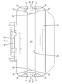
- FIG. 14
- the card edge connector of the present disclosure is (1) A tubular hood portion, a circuit board arranged in the hood portion, a housing fitted in the hood portion and having a storage space for the circuit board, and a terminal fitting accommodated in the housing.
- the terminal fitting has a contact portion that faces the accommodation space and is electrically connected to the circuit board.
- the protective member is located on the opening side of the accommodation space at the initial position to restrict the connection between the circuit board and the contact portion, and retreats from the opening side of the accommodation space at the connection position.
- the hood portion has a main body portion that allows connection between the substrate and the contact portion, and a hooked portion that is connected to the end portion of the main body portion and projects to the outer surface side of the housing, and the hood portion is the outer surface of the housing.
- the hooked portion is provided on the inner surface opposite to the hooked portion so as to hook the hooked portion and move the protective member from the connecting position to the initial position.
- the main body when the protective member is in the initial position, the main body is located on the opening side of the accommodation space, so that the circuit board inserted in the accommodation space hits the main body and the contact portion of the terminal fitting is a circuit. It is possible to avoid interfering with the substrate.
- the main body portion retreats from the opening side of the accommodation space to the back side, and the connection state between the contact portion and the circuit board can be realized. Since it is possible to prevent the contact portion of the terminal fitting from hitting the corner portion of the circuit board or the like, the connection state between the contact portion of the terminal fitting and the circuit board can be satisfactorily realized.
- the hooked portion of the hood portion hooks the hooked portion of the protective member and returns the protective member to the initial position. be able to. Since the hook portion is provided on the inner surface of the hood portion, the degree of freedom in design and the dimensional accuracy of the hook portion can be increased.
- the hooked portion has a shape that allows it to bend and deform with a portion connected to the end portion of the main body portion as a fulcrum, and the housing has the hooked portion on the outer surface in a state where the protective member is in the initial position. It is preferable that the protective member is located away from the bending space of the portion and has a regulating surface located in the bending space of the hooked portion in a state where the protective member is in the connecting position.
- the hooked portion comes into contact with the hooked portion in the state where the protective member is in the initial position, and the hooked portion can be bent.
- the hooked portion elastically returns, and the hooked portion can get over the hooked portion.
- the bending motion of the hooked portion is regulated by the regulation surface of the housing.
- the circuit board is pulled out from the accommodation space, the bending operation of the hooked portion is regulated, so that it is possible to prevent the hooked portion and the hooked portion from being inadvertently released. can.
- the circuit board has an end surface having a pressing surface that hits the protective member at the initial position and moves the protective member to the connection position, and the protective member holds a plurality of elastically deformable bendable members.
- the housing has a plurality of holding portions for locking the plurality of elastic holding portions and restricting the movement of the protective member from the initial position to the connecting position, and the hooking portion. It is preferable that there is a gap between the pressing surface of the circuit board and the protective member in a state where the hooked portion is hooked at the connection position.
- a gap is formed between the pressing surface of the circuit board and the protective member when the hooked portion hooks the hooked portion, and within the range of the gap. Tilt movement of the protective member is allowed. By tilting the protective member, the timing at which each elastic holding portion gets over each holding portion can be shifted when the protective member returns to the initial position. The peak can be made smaller.
- the card edge connector is composed of a female side connector 10 and a male side connector 60 that can be fitted to each other.
- the male connector 60 includes a hood portion 61 and a circuit board 62.
- the female connector 10 includes housings 11 and 12, a plurality of terminal fittings 13, and a protective member 14. Further, the housings 11 and 12 are composed of an outer housing 11 and an inner housing 12.
- the circuit board 62 is arranged in the hood portion 61.
- the terminal fitting 13 is housed in the housings 11 and 12.
- the protective member 14 is movably assembled to the housings 11 and 12 at an initial position (see FIG. 5) and a connection position (see FIG. 2).
- the protective member 14 protects the contact portion 25 described later of the terminal fitting 13 at the initial position.
- the contact portion 25 of the terminal fitting 13 is electrically connected to the conductive portion 65 of the circuit board 62 at the time of regular fitting of both connectors 10 and 60.
- the vertical direction is based on the vertical direction of FIG. In the front-rear direction, the front side is the side on which both connectors 10 and 60 face each other at the start of fitting.
- the hood portion 61 is made of synthetic resin, has a square tubular shape as shown in FIGS. 1 and 2, and penetrates in the front-rear direction.
- the hood portion 61 is formed in a horizontally long shape in which the width dimension in the left-right direction is larger than the height dimension in the vertical direction.
- a lock hole 63 is provided on the upper wall of the hood portion 61.
- the hood portion 61 has a pair of hook portions 64 on the inner surfaces of the left and right side walls.
- Each hook portion 64 is provided in a trapezoidal shape at the central portion in the vertical direction of the front end portion on the inner surface of the left and right side walls.
- the end surface (hereinafter, referred to as an inner end surface) of each hook portion 64 in the protruding direction has a flat shape along the front-rear direction.
- the front surface of each hook portion 64 is tapered rearward from the open end of the hood portion 61 toward the inner end surface.
- the rear surface of each hook portion 64 is tapered forward toward the inner end surface.
- the hood portion 61 is attached to a case (not shown).
- the circuit board 62 is also attached to the case. Therefore, the relative positions of the circuit board 62 and the hood portion 61 are kept constant.
- the circuit board 62 has a rectangular shape in a plan view, and is arranged in the central portion in the vertical direction in the hood portion 61 with the plate surface facing in the vertical direction.
- a plurality of conductive portions 65 are provided side by side in the width direction on the surface of the circuit board 62. Each conductive portion 65 is arranged at a position corresponding to each terminal fitting 13.
- the circuit board 62 has a pressing surface 66 that presses the protective member 14 on the front end surface (thick surface) along the width direction.
- the pressing surface 66 is composed of the entire front end surface of the circuit board 62.
- the inner housing 12 is made of synthetic resin and has a plurality of cavities 15 as shown in FIG. As shown in FIG. 2, a plurality of cavities 15 are arranged side by side in the width direction in two upper and lower stages in the inner housing 12. Each cavity 15 has a vertically long slit shape and penetrates in the front-rear direction.
- each of the upper cavities 15 is opened on the upper surface of the inner housing 12, and has steps 16 and 17 in the front-rear direction along the vertical direction at two locations spaced apart from each other in the front-rear direction. There is. Of each of the upper cavities 15, the vertical depth between the front and rear steps 16 and 17 is deeper than the vertical depth between the front and rear steps 16 and 17. Further, as shown in FIG. 6, the upper portion of each of the upper cavities 15 is formed so that the opening width in the left-right direction is larger than that of the lower portion of each of the upper cavities 15.
- the terminal fitting 13 is inserted into each of the upper cavities 15 from above.
- the inner housing 12 has a retaining portion 18 that restricts the terminal fitting 13 inserted into each of the upper cavities 15 from coming out upward.
- the retaining portions 18 project in pairs with the left and right inner surfaces in the upper part of each cavity 15 in the upper stage.
- Each of the lower cavities 15 is opened on the lower surface of the inner housing 12, and has steps 16 and 17 in the front-rear direction along the vertical direction at two locations spaced apart from each other in the front-rear direction. ing.
- the vertical depth between the front and rear steps 16 and 17 is deeper than the vertical depth between the front and rear steps 16 and 17.
- the lower portion of each of the lower cavities 15 is formed so that the opening width in the left-right direction is larger than that of the upper portion of each of the lower cavities 15.
- the terminal fitting 13 is inserted into each of the lower cavities 15 from below.
- the inner housing 12 has a retaining portion 18 that restricts the terminal fitting 13 inserted into each of the lower cavities 15 from coming out downward.
- the retaining portions 18 project in pairs with the left and right inner surfaces at the lower part of each of the lower cavities 15.
- the upper and lower cavities 15 are arranged so as to be displaced from each other in the width direction. Specifically, the wide upper portion of each of the upper cavities 15 and the narrow upper portion of each of the lower cavities 15 are arranged side by side in the width direction. Further, the narrow lower portion of each of the upper cavities 15 and the wide lower portion of each of the lower cavities 15 are arranged side by side in the width direction. In this way, the upper and lower cavities 15 are provided in the inner housing 12 so as to be aligned at a narrow pitch in the vertical direction and the horizontal direction in a space-efficient manner.
- the inner housing 12 has a pair of locking projections 19 in the width direction at the center of the front end portion of the upper surface in the width direction. Further, the inner housing 12 has a horizontally long slit-shaped accommodating space 21 that opens in the central portion in the vertical direction on the front surface.
- the accommodation space 21 is formed over the entire width of the inner housing 12, and is also open to the left and right side surfaces of the inner housing 12.
- the accommodation space 21 communicates with each cavity 15 via a step 16 on the front side.
- the inner end of the accommodation space 21 is closed by the step 17 on the rear side.
- the circuit board 62 is inserted into the accommodation space 21 through the communication port 29 described later.
- the terminal fitting 13 is formed by bending a conductive metal plate or the like.
- the rear portion of the terminal fitting 13 is connected to the end portion of the electric wire 20.
- the front portion of the terminal fitting 13 has a square tubular portion 22 coaxially with the electric wire 20 in the front-rear direction, and is positioned to face the tubular portion 22 in the height direction. It has a plate-shaped portion 23 along the front-rear direction.
- the tubular portion 22 has an open surface facing the plate-shaped portion 23.
- the front portion of the terminal fitting 13 has an elastic contact piece 24 that can be flexed and deformed inside the tubular portion 22.
- the elastic contact piece 24 has a chevron shape protruding toward the plate-shaped portion 23 through the opening surface of the tubular portion 22, and has a contact portion 25 at the top portion closest to the plate-shaped portion 23. As shown in FIG. 5, the separation distance between the tubular portion 22 and the plate-shaped portion 23 corresponds to the opening dimension in the height direction of the accommodation space 21.
- the tubular portion 22 of the terminal fitting 13 is inserted into a wide upper portion in each upper cavity 15 or a wide lower portion in each lower cavity 15.
- the plate-shaped portion 23 of the terminal fitting 13 is inserted into the lower part of the narrow width in each of the upper cavities 15 or the upper part of the narrow width in each of the lower cavities 15.
- the circuit board 62 is inserted from the front between the tubular portion 22 and the plate-shaped portion 23.
- the elastic contact piece 24 is in a state of being flexed and deformed, and the contact portion 25 is brought into contact with the conductive portion 65 of the circuit board 62.
- the outer housing 11 is made of synthetic resin, and has a housing assembly space 26 that opens to the rear surface inside.
- the outer housing 11 has a front wall 27 on the front surface.
- the outer housing 11 has a terminal holding portion 28 protruding from the front wall 27 into the housing assembly space 26.
- the inner housing 12 is inserted into the housing assembly space 26 from the rear.
- a plurality of terminal holding portions 28 are arranged at the upper and lower positions corresponding to the respective cavities 15.
- the inner housing 12 is movably assembled to the outer housing 11 at the temporary locking position and the main locking position.
- the inner housing 12 is shallowly inserted into the housing assembly space 26 at the temporary locking position, and as shown in FIG. 4, the upper surface opening of each upper cavity 15 and the lower surface opening of each lower cavity 15 of the outer housing 11 are inserted into the outer housing 11. It is placed exposed behind.
- each terminal fitting 13 is inserted into each cavity 15.
- the rear end of the outer housing 11 is provided with a stop 47 (see FIG. 5) that hits each locking projection 19 and restricts the inner housing 12 in the temporarily locked position from coming out to the rear. ..
- the inner housing 12 is inserted into the housing assembly space 26 at a regular depth at the main locking position, and as shown in FIG. 5, the upper terminal holders are held in front of the upper opening of each upper cavity 15.
- the portion 28 enters, and each terminal holding portion 28 in the lower stage enters and is arranged in front of the lower surface opening of each cavity 15 in the lower stage.
- the terminal fittings 13 are restricted from coming out in the vertical direction.
- the inner housing 12 is placed in contact with the front wall 27 of the outer housing 11 at the main locking position.
- the outer housing 11 has a horizontally long communication port 29 that opens at the central portion in the vertical direction of the front wall 27.
- the communication port 29 communicates with the housing assembly space 26, and also communicates with the accommodation space 21 in a state where the inner housing 12 is inserted into the housing assembly space 26.
- the outer housing 11 has a pair of vertical grooves 31 extending from the left and right ends of the communication port 29 to both the upper and lower sides.
- the outer housing 11 has a first holding portion 32 and a second holding portion 33 on the upper and lower surfaces of each vertical groove 31.
- the first holding portion 32 and the second holding portion 33 are displaced from each other in the front-rear direction and the width direction.
- the first holding portion 32 is provided on the inner rear side of the second holding portion 33.
- An elastic holding portion 43, which will be described later, of the protective member 14 can be locked to the first holding portion 32 and the second holding portion 33.
- the outer housing 11 has a pair of groove portions 34 that open on the left and right side surfaces. Each groove 34 extends over the entire length of the outer housing 11 in the front-rear direction and opens on the front-rear surface of the outer housing 11. Each groove 34 communicates with each vertical groove 31. As shown in FIG. 8, the outer housing 11 has a pair of wall portions 35 at the rear portions closer to the left and right side surfaces. The front end of each wall portion 35 is located at the rear end of each vertical groove 31. The inner surface of each wall portion 35 is arranged along the front-rear direction and faces the housing assembly space 26. The outer surface of each wall portion 35 is arranged along the front-rear direction and faces each groove portion 34.
- each wall portion 35 is configured as a regulating surface 36 that regulates the bending operation of the hooked portion 42 described later of the protective member 14. Further, as shown in FIG. 3, a lock arm 37 that can be flexed and deformed is projected from the upper surface of the outer housing 11. The lock arm 37 has a lock protrusion 38 that fits into the lock hole 63 of the hood portion 61.
- the protective member 14 is made of synthetic resin, and as shown in FIG. 3, a horizontal bar-shaped main body 41 that is long in the width direction and a pair of hooked portions 42 that are connected to both ends of the main body 41 in the width direction and extend to both front and rear sides. It has a pair of elastic holding portions 43 extending in a bifurcated manner from the front end of the hooked portion 42 to the upper rear and the lower rear.
- the main body 41 is formed in a size that can be inserted into the accommodation space 21. As shown in FIG. 5, the rear portion of the main body 41 has a shape in which the vertical dimension is gradually reduced toward the rear.
- the main body 41 has a receiving surface 44 arranged along the left-right direction on the front surface. As shown in FIG. 2, the receiving surface 44 of the main body 41 comes into contact with the pressing surface 66 of the circuit board 62 and is pressed.
- each hooked portion 42 has a long arm shape in the front-rear direction, and can be bent and deformed in the width direction with a portion connected to the main body portion 41 as a fulcrum.
- Each hooked portion 42 has a hooking protrusion 45 that projects outward in the width direction in a claw shape on the outer surface of the rear end portion.
- the front surface of the hook projection 45 is arranged along the left-right direction.
- the rear surface of the hooking protrusion 45 is inclined rearward in a tapered shape.
- each elastic holding portion 43 has an arm shape that protrudes in a direction away from the hooked portion 42 and then extends rearward, and can be bent and deformed in the vertical direction with a portion connected to the hooked portion 42 as a fulcrum. Has been done.
- the total length of each elastic holding portion 43 is shorter than the total length of each hooked portion 42.
- Each elastic holding portion 43 has a holding protrusion 46 protruding outward in the height direction in a claw shape on the outer surface of the rear end portion.
- the front surface of the holding protrusion 46 is arranged along the vertical direction.
- the rear surface of the holding projection 46 is tapered rearward.
- each terminal fitting 13 is inserted into the upper cavities 15 of the inner housing 12 from above, and the terminal fittings 13 are inserted into the lower cavities 15 of the inner housing 12 from below.
- the tubular portion 22 of each terminal fitting 13 is fitted between the front and rear steps 16 and 17, and is arranged so as to hit the front and rear steps 16 and 17.
- the displacement of each terminal fitting 13 with respect to the inner housing 12 in the front-rear direction is regulated (see FIG. 5).
- the tubular portion 22 of each terminal fitting 13 is arranged so as to hit the left and right retaining portions 18 from the inside (see FIG. 6).
- the exit of each terminal fitting 13 from each cavity 15 is temporarily restricted.
- the terminal fittings 13 are arranged side by side in the inner housing 12 so as to face the accommodation space 21 in a state where the height positions of the contact portions 25 are aligned at the same position. Subsequently, the inner housing 12 is pushed against the outer housing 11 and moved toward the main locking position. When the inner housing 12 reaches the main locking position, each terminal holding portion 28 is arranged along the flat plate portion of the tubular portion 22 of each terminal fitting 13 (see FIG. 5). As a result, the exit of each terminal fitting 13 from each cavity 15 is secondarily and surely regulated.
- the protective member 14 is arranged at an initial position with respect to the outer housing 11.
- Each elastic holding portion 43 enters the vertical groove 31, and the holding projection 46 of each elastic holding portion 43 is arranged so as to be sandwiched between the first holding portion 32 and the second holding portion 33 in the front-rear direction (FIG. 7).
- the displacement of the protective member 14 with respect to the outer housing 11 in the front-rear direction is regulated.
- the main body 41 is arranged so as to fit into the inner space on the opening side of the accommodation space 21 (see FIG. 5). Further, the hooked portion 42 enters the housing assembly space 26 and the groove portion 34 from the communication port 29.
- the hooking projection 45 of the hooked portion 42 is displaced in the groove portion 34.
- the hook projection 45 of the hooked portion 42 is located on the back end side (rear end side) of the groove portion 34 and is arranged so as to project into the groove portion 34 (see FIG. 3). ..
- both connectors 10 and 60 are fitted to each other.
- the outer housing 11 is shallowly fitted in the hood portion 61, and each hook portion 64 enters the groove portion 34.
- the inner end surfaces of the hooked portions 64 are arranged so as to be in contact with each other along the outer surface of the hooked portions 42 of the protective member 14 (see FIG. 8).
- the hooking portion 64 slides into contact with the hooking protrusion 45 of the hooked portion 42, and the hooked portion 42 bends into the vertical groove 31 (the bending space on the housing assembly space 26 side). It can be transformed (see FIG. 9).
- a gap is secured between the hooked portion 42 that bends and deforms and the wall portion 35, and the hooked portion 42 does not interfere with the wall portion 35.
- the protective member 14 When the mating of both connectors 10 and 60 further progresses, the protective member 14 is pushed by the circuit board 62 and moved toward the connection position.
- the main body 41 is displaced from the opening side of the accommodation space 21 toward the back side. During this time, the contact state between the circuit board 62 and the main body 41 is maintained, and the circuit board 62 does not come into contact with the contact portion 25 of the terminal fitting 13.
- the elastic contact piece 24 slides on the slope portion of the main body 41 and is flexed and deformed.
- the elastic contact piece 24 elastically returns, and the contact portion 25 of the elastic contact piece 24 gets over the main body portion 41 and comes into contact with the conductive portion 65 of the circuit board 62.
- the contact portion 25 of each terminal fitting 13 and each conductive portion 65 of the circuit board 62 are electrically connected (see FIG. 2).
- the lock protrusion 38 of the lock arm 37 is fitted into the lock hole 63 of the hood portion 61, so that both the connectors 10 and 60 are held in the fitted state.
- the rear inner surface of the hooked portion 42 is arranged along the regulation surface 36 of the wall portion 35 (see FIG. 11).
- the pressing surface 66 of the circuit board 62 is in front of the receiving surface 44 of the main body portion 41. Placed apart. That is, a gap in the front-rear direction is formed between the main body 41 of the protective member 14 and the circuit board 62.
- each elastic holding portion 43 is arranged in pairs on the protective member 14 at the top and bottom, there is a concern that the resistance due to the interference between each elastic holding portion 43 and each first holding portion 32 increases.
- the protective member 14 can be tilted within the range of the gap, and each elastic holding is performed.
- the timing at which the holding projection 46 of the portion 43 hits each of the first holding portions 32 can be individually shifted.
- the resistance caused by the interference between each elastic holding portion 43 and each first holding portion 32 does not increase at once, and the peak of the resistance can be suppressed to a small value.
- the elastic holding portions 43 are elastically restored, and the holding projections 46 of the elastic holding portions 43 are again between the first holding portion 32 and the second holding portions 33. Arranged so as to be sandwiched.
- the protective member 14 is surely held in a temporarily locked position in a state where the detachment is restricted. As a result, the protective member 14 returns to the temporarily locked position and can be used repeatedly.
- the main body 41 when the protective member 14 is in the initial position, the main body 41 is located on the opening side of the accommodation space 21, so that the circuit board 62 inserted in the accommodation space 21 is It is possible to prevent the contact portion 25 of the terminal fitting 13 from interfering with the circuit board 62 when it hits the main body portion 41.
- the protective member 14 is in the connection position, the main body 41 is retracted from the opening side of the accommodation space 21, and the connection state between the contact portion 25 and the circuit board 62 can be realized. Since it is possible to prevent the contact portion 25 of the terminal fitting 13 from hitting the corner portion of the circuit board 62 or the like, the connection state between the contact portion 25 of the terminal fitting 13 and the circuit board 62 can be satisfactorily realized.
- the hooking portion 64 hooks the hooked portion 42 in the process of detaching the hood portion 61 from the housings 11 and 12, and the protective member 14 may be returned to the initial position. can.
- the hook portion 64 is provided on the inner surface of the hood portion 61, the degree of freedom in design and the dimensional accuracy of the hook portion 64 can be increased.
- the hooked portion 64 can come into contact with the hooked portion 42 in a state where the protective member 14 is in the initial position, and the hooked portion 42 can be bent.
- the bending operation of the hooked portion 42 is regulated by the regulation surface 36 of the housings 11 and 12.
- the circuit board 62 is pulled out from the accommodation space 21, the bending operation of the hooked portion 42 is restricted, so that the hooked state between the hooked portion 64 and the hooked portion 42 is inadvertently released. Can be prevented.
- the housing is composed of the outer housing and the inner housing, but in other embodiments, the housing may be integrally formed inseparably.
- the hooking portion is provided in a fixed state on the hood portion, and the hooked portion is provided on the end portion of the protective member so as to be deformable, but in other embodiments, the hooking portion is bent on the hood portion. It may be provided so as to be deformable, and the hooked portion may be provided in a fixed state at the end portion of the protective member.
- the elastic holding portion is provided with the holding protrusion
- the housing is provided with the first holding portion and the second holding portion
- the holding protrusion is sandwiched between the first holding portion and the second holding portion.
- the elastic holding portion may be provided with two holding protrusions
- the housing may be provided with one holding portion
- the holding portion of the housing may be sandwiched between the two holding protrusions of the elastic holding portion.
- Elastic holding part 44 Receiving surface 45 ... Hooking protrusion 46 ... Holding protrusion 47 ... Stopping part 60 ... Male side connector 61 ... Hood part 62 ... Circuit board 63 ... Lock hole 64 ... Hooking part 65 ... Conductive part 66 ... Pressing surface
Abstract
A hood part (61) has a circuit substrate (62) disposed therewithin. The hood part (61) also has fitted therein a housing (11, 12) having an accommodation space (21) formed therein. The housing (11, 12) has disposed therein a protective member (14) that is disposed so as to be movable to an initial position and a connecting position. A terminal fitting (13) has a contact point part (25) that faces the accommodation space (21). The protective member (14) comprises: a body (41) which is positioned on an opening side of the accommodation space (21) when disposed at the initial position and which is withdrawn from the opening side of the accommodation space (21) when disposed at the connecting position; and a hooked part (42) which is formed contiguous to an end portion of the body (41). The hood part (61) has formed on an inner peripheral surface thereof a hooking part (64) which is hooked to the hooked part (42) so as to cause the protective member (14) to be moved from the connecting position to the initial position.
Description
本開示は、カードエッジコネクタに関する。
This disclosure relates to a card edge connector.
特許文献1に記載されたカードエッジコネクタは、回路基板と、回路基板が挿入される基板収容空間を有するハウジングと、ハウジング内に収容される端子金具と、ハウジングに初期位置と接続位置とに移動可能に配置される可動部材(以下、保護部材と称する)と、を備えている。端子金具は、回路基板に弾性的に接触する弾性接触片を有している。保護部材は、初期位置である基板収容空間の開口側において回路基板の端面を覆う。保護部材は、回路基板に押されて接続位置である基板収容空間の奥側に移動する。保護部材は係止突部を有し、回路基板は係止凹部を有している。係止突部および係止凹部は、回路基板の抜き取り時に、互いに係止される。
The card edge connector described in Patent Document 1 moves to a circuit board, a housing having a board storage space into which the circuit board is inserted, a terminal fitting housed in the housing, and an initial position and a connection position in the housing. It includes a movable member (hereinafter, referred to as a protective member) that can be arranged so as to be possible. The terminal fitting has an elastic contact piece that elastically contacts the circuit board. The protective member covers the end face of the circuit board on the opening side of the substrate accommodation space, which is the initial position. The protective member is pushed by the circuit board and moves to the inner side of the board accommodation space, which is the connection position. The protective member has a locking protrusion, and the circuit board has a locking recess. The locking protrusion and the locking recess are locked to each other when the circuit board is pulled out.
保護部材が初期位置にあるときに、回路基板の端面が基線収容空間の開口側で保護部材に覆われることにより、端子金具の弾性接触片が回路基板と干渉するのを回避することができる。回路基板を基板収容空間から抜き取る際には、係止突起および係止凹部が互いに係止された状態になっていることで、保護部材が回路基板と一体になって初期位置に戻ることができる。
When the protective member is in the initial position, the end face of the circuit board is covered with the protective member on the opening side of the baseline accommodation space, so that the elastic contact piece of the terminal fitting can be prevented from interfering with the circuit board. When the circuit board is pulled out from the board accommodation space, the locking projection and the locking recess are in a state of being locked to each other, so that the protective member can be integrated with the circuit board and returned to the initial position. ..
ところで、回路基板は加工性に劣るため、回路基板に設けられる係止凹部の設計自由度が低いという問題がある。また、フード部内における回路基板の設置位置が適正でないと、係止突起および係止凹部の係止状態を実現することができないおそれもある。
By the way, since the circuit board is inferior in workability, there is a problem that the degree of freedom in designing the locking recess provided in the circuit board is low. Further, if the installation position of the circuit board in the hood portion is not appropriate, the locking state of the locking projection and the locking recess may not be realized.
そこで、本開示は、保護部材を初期位置に戻す構造の設計自由度および寸法精度を高めたカードエッジコネクタを提供することを目的とする。
Therefore, an object of the present disclosure is to provide a card edge connector having an increased degree of freedom in design and dimensional accuracy of a structure for returning a protective member to an initial position.
本開示のカードエッジコネクタは、筒状のフード部と、前記フード部内に配置される回路基板と、前記フード部内に嵌合され、前記回路基板の収容空間を有するハウジングと、前記ハウジング内に収容される端子金具と、前記ハウジング内に初期位置と接続位置とに移動可能に配置される保護部材と、を備え、前記端子金具は、前記収容空間に臨み、前記回路基板に電気的に接続される接点部を有し、前記保護部材は、前記初期位置において前記収容空間の開口側に位置して前記回路基板と前記接点部との接続を規制し、前記接続位置において前記収容空間の開口側から退いて前記回路基板と前記接点部との接続を許容する本体部と、前記本体部の端部に連なり、前記ハウジングの外面側に突出する被引掛部と、を有し、前記フード部は、前記ハウジングの外面と対向する内面に、前記被引掛部を引っ掛けて前記保護部材を前記接続位置から前記初期位置に移動させる引掛部を有している。
The card edge connector of the present disclosure includes a tubular hood portion, a circuit board arranged in the hood portion, a housing fitted in the hood portion and having a storage space for the circuit board, and a housing contained in the housing. The terminal fitting is provided with a protective member movably arranged in the housing at an initial position and a connection position, and the terminal fitting faces the accommodation space and is electrically connected to the circuit board. The protective member is located on the opening side of the accommodation space at the initial position to restrict the connection between the circuit board and the contact portion, and at the connection position, the opening side of the accommodation space. The hood portion has a main body portion that allows connection between the circuit board and the contact portion, and a hooked portion that is connected to the end portion of the main body portion and projects to the outer surface side of the housing. The inner surface of the housing facing the outer surface has a hooking portion for hooking the hooked portion to move the protective member from the connecting position to the initial position.
本開示によれば、保護部材を初期位置に戻す構造の設計自由度および寸法精度を高めたカードエッジコネクタを提供することが可能となる。
According to the present disclosure, it is possible to provide a card edge connector having an increased degree of freedom in design and dimensional accuracy of a structure for returning a protective member to an initial position.
[本開示の実施形態の説明]
最初に本開示の実施態様を列記して説明する。
本開示のカードエッジコネクタは、
(1)筒状のフード部と、前記フード部内に配置される回路基板と、前記フード部内に嵌合され、前記回路基板の収容空間を有するハウジングと、前記ハウジング内に収容される端子金具と、前記ハウジング内に初期位置と接続位置とに移動可能に配置される保護部材と、を備え、前記端子金具は、前記収容空間に臨み、前記回路基板に電気的に接続される接点部を有し、前記保護部材は、前記初期位置において前記収容空間の開口側に位置して前記回路基板と前記接点部との接続を規制し、前記接続位置において前記収容空間の開口側から退いて前記回路基板と前記接点部との接続を許容する本体部と、前記本体部の端部に連なり、前記ハウジングの外面側に突出する被引掛部と、を有し、前記フード部は、前記ハウジングの外面と対向する内面に、前記被引掛部を引っ掛けて前記保護部材を前記接続位置から前記初期位置に移動させる引掛部を有している。 [Explanation of Embodiments of the present disclosure]
First, embodiments of the present disclosure will be listed and described.
The card edge connector of the present disclosure is
(1) A tubular hood portion, a circuit board arranged in the hood portion, a housing fitted in the hood portion and having a storage space for the circuit board, and a terminal fitting accommodated in the housing. The terminal fitting has a contact portion that faces the accommodation space and is electrically connected to the circuit board. The protective member is located on the opening side of the accommodation space at the initial position to restrict the connection between the circuit board and the contact portion, and retreats from the opening side of the accommodation space at the connection position. The hood portion has a main body portion that allows connection between the substrate and the contact portion, and a hooked portion that is connected to the end portion of the main body portion and projects to the outer surface side of the housing, and the hood portion is the outer surface of the housing. The hooked portion is provided on the inner surface opposite to the hooked portion so as to hook the hooked portion and move the protective member from the connecting position to the initial position.
上記構成によれば、保護部材が初期位置にあるときに、本体部が収容空間の開口側に位置するため、収容空間に挿入された回路基板が本体部と当たり、端子金具の接点部が回路基板と干渉するのを回避することができる。保護部材が接続位置にあるときには、本体部が収容空間の開口側から奥側に退いて、接点部と回路基板との接続状態を実現することができる。端子金具の接点部が回路基板の角部等に当たるのを防止することができるため、端子金具の接点部と回路基板との接続状態を良好に実現することができる。
According to the above configuration, when the protective member is in the initial position, the main body is located on the opening side of the accommodation space, so that the circuit board inserted in the accommodation space hits the main body and the contact portion of the terminal fitting is a circuit. It is possible to avoid interfering with the substrate. When the protective member is in the connection position, the main body portion retreats from the opening side of the accommodation space to the back side, and the connection state between the contact portion and the circuit board can be realized. Since it is possible to prevent the contact portion of the terminal fitting from hitting the corner portion of the circuit board or the like, the connection state between the contact portion of the terminal fitting and the circuit board can be satisfactorily realized.
また、上記構成によれば、回路基板を収容空間から抜き取る際に、フード部をハウジングから離脱する過程において、フード部の引掛部が保護部材の被引掛部を引っ掛けて保護部材を初期位置に戻すことができる。引掛部がフード部の内面に設けられているため、引掛部の設計自由度および寸法精度を高めることができる。
Further, according to the above configuration, when the circuit board is pulled out from the accommodation space, in the process of separating the hood portion from the housing, the hooked portion of the hood portion hooks the hooked portion of the protective member and returns the protective member to the initial position. be able to. Since the hook portion is provided on the inner surface of the hood portion, the degree of freedom in design and the dimensional accuracy of the hook portion can be increased.
(2)前記被引掛部は、前記本体部の端部に連なる部位を支点として撓み変形可能な形状をなし、前記ハウジングは、外面に、前記保護部材が前記初期位置にある状態で前記被引掛部の撓み空間から離れて位置し、前記保護部材が前記接続位置にある状態で前記被引掛部の撓み空間に位置する規制面を有しているのが好ましい。
(2) The hooked portion has a shape that allows it to bend and deform with a portion connected to the end portion of the main body portion as a fulcrum, and the housing has the hooked portion on the outer surface in a state where the protective member is in the initial position. It is preferable that the protective member is located away from the bending space of the portion and has a regulating surface located in the bending space of the hooked portion in a state where the protective member is in the connecting position.
上記構成によれば、保護部材が初期位置にある状態で引掛部が被引掛部と接触し、被引掛部を撓ませることができる。フード部およびハウジングの嵌合過程で被引掛部が弾性復帰し、引掛部が被引掛部を乗り越えることができる。フード部およびハウジングが正規に嵌合され、保護部材が接続位置に至ると、被引掛部の撓み動作がハウジングの規制面によって規制される。回路基板を収容空間から抜き取る際に、被引掛部の撓み動作が規制された状態になっているから、引掛部と被引掛部との引っ掛け状態が不用意に解除されるのを防止することができる。
According to the above configuration, the hooked portion comes into contact with the hooked portion in the state where the protective member is in the initial position, and the hooked portion can be bent. In the process of fitting the hood portion and the housing, the hooked portion elastically returns, and the hooked portion can get over the hooked portion. When the hood portion and the housing are properly fitted and the protective member reaches the connection position, the bending motion of the hooked portion is regulated by the regulation surface of the housing. When the circuit board is pulled out from the accommodation space, the bending operation of the hooked portion is regulated, so that it is possible to prevent the hooked portion and the hooked portion from being inadvertently released. can.
(3)前記回路基板は、端面に、前記初期位置にある前記保護部材に当たり、前記保護部材を前記接続位置に移動させる押圧面を有し、前記保護部材は、撓み変形可能な複数の弾性保持部を有し、前記ハウジングは、前記複数の弾性保持部をそれぞれ係止し、前記保護部材の前記初期位置から前記接続位置への移動を規制する、複数の保持部を有し、前記引掛部が前記接続位置において前記被引掛部を引っ掛けた状態において、前記回路基板の前記押圧面と前記保護部材との間に隙間を有していると良い。
(3) The circuit board has an end surface having a pressing surface that hits the protective member at the initial position and moves the protective member to the connection position, and the protective member holds a plurality of elastically deformable bendable members. The housing has a plurality of holding portions for locking the plurality of elastic holding portions and restricting the movement of the protective member from the initial position to the connecting position, and the hooking portion. It is preferable that there is a gap between the pressing surface of the circuit board and the protective member in a state where the hooked portion is hooked at the connection position.
上記構成によれば、回路基板を収容空間から抜き取る際に、引掛部が被引掛部を引っ掛けたときに、回路基板の押圧面と保護部材との間に隙間が形成され、その隙間の範囲で保護部材の傾き動作が許容される。保護部材が傾くことで、保護部材が初期位置に戻る際に各弾性保持部が各保持部を乗り越えるタイミングをずらすことができるため、各弾性保持部と各保持部との干渉に起因する抵抗のピークを小さくすることができる。
According to the above configuration, when the circuit board is pulled out from the accommodation space, a gap is formed between the pressing surface of the circuit board and the protective member when the hooked portion hooks the hooked portion, and within the range of the gap. Tilt movement of the protective member is allowed. By tilting the protective member, the timing at which each elastic holding portion gets over each holding portion can be shifted when the protective member returns to the initial position. The peak can be made smaller.
[本開示の実施形態の詳細]
本開示のカードエッジコネクタの具体例を、以下に図面を参照しつつ説明する。なお、本発明はこの例示に限定されるものではなく、特許請求の範囲によって示され、特許請求の範囲と均等の意味および範囲内でのすべての変更が含まれることが意図される。 [Details of Embodiments of the present disclosure]
Specific examples of the card edge connector of the present disclosure will be described below with reference to the drawings. It should be noted that the present invention is not limited to this example, and is indicated by the scope of claims, and is intended to include all modifications within the meaning and scope equivalent to the scope of claims.
実施形態に係るカードエッジコネクタは、互いに嵌合可能な雌側コネクタ10と雄側コネクタ60とにより構成される。図1に示すように、雄側コネクタ60は、フード部61と回路基板62とを備えている。雌側コネクタ10は、ハウジング11、12と複数の端子金具13と保護部材14とを備えている。さらに、ハウジング11、12は、アウタハウジング11とインナハウジング12とからなる。
The card edge connector according to the embodiment is composed of a female side connector 10 and a male side connector 60 that can be fitted to each other. As shown in FIG. 1, the male connector 60 includes a hood portion 61 and a circuit board 62. The female connector 10 includes housings 11 and 12, a plurality of terminal fittings 13, and a protective member 14. Further, the housings 11 and 12 are composed of an outer housing 11 and an inner housing 12.
図2に示すように、回路基板62は、フード部61内に配置される。端子金具13は、ハウジング11、12に収容される。保護部材14は、ハウジング11、12に対し初期位置(図5を参照)と接続位置(図2を参照)とに移動可能に組み付けられる。保護部材14は、初期位置において、端子金具13の後述する接点部25を保護する。端子金具13の接点部25は、両コネクタ10、60の正規嵌合時に、回路基板62の導電部65に導通接続される。なお、以下の説明において、上下方向は、図2の上下方向を基準とする。前後方向は、両コネクタ10、60が嵌合開始時に互いに向き合う面側を前側とする。
As shown in FIG. 2, the circuit board 62 is arranged in the hood portion 61. The terminal fitting 13 is housed in the housings 11 and 12. The protective member 14 is movably assembled to the housings 11 and 12 at an initial position (see FIG. 5) and a connection position (see FIG. 2). The protective member 14 protects the contact portion 25 described later of the terminal fitting 13 at the initial position. The contact portion 25 of the terminal fitting 13 is electrically connected to the conductive portion 65 of the circuit board 62 at the time of regular fitting of both connectors 10 and 60. In the following description, the vertical direction is based on the vertical direction of FIG. In the front-rear direction, the front side is the side on which both connectors 10 and 60 face each other at the start of fitting.
(フード部および回路基板)
フード部61は合成樹脂製であって、図1および図2に示すように、角筒状をなし、前後方向に貫通している。フード部61は、上下方向の高さ寸法よりも左右方向の幅寸法を大きくした横長形状に形成されている。フード部61の上壁には、ロック孔63が設けられている。 (Hood and circuit board)
Thehood portion 61 is made of synthetic resin, has a square tubular shape as shown in FIGS. 1 and 2, and penetrates in the front-rear direction. The hood portion 61 is formed in a horizontally long shape in which the width dimension in the left-right direction is larger than the height dimension in the vertical direction. A lock hole 63 is provided on the upper wall of the hood portion 61.
フード部61は合成樹脂製であって、図1および図2に示すように、角筒状をなし、前後方向に貫通している。フード部61は、上下方向の高さ寸法よりも左右方向の幅寸法を大きくした横長形状に形成されている。フード部61の上壁には、ロック孔63が設けられている。 (Hood and circuit board)
The
フード部61は、図8に示すように、左右側壁の内面に、一対の引掛部64を有している。各引掛部64は、左右側壁の内面における前端部の上下方向中央部に台状に突設されている。各引掛部64の突出方向の端面(以下、内端面と称する)は、前後方向に沿った平坦な形状になっている。各引掛部64の前面は、フード部61の開口端から内端面に向けて後方にテーパ状に傾斜している。各引掛部64の後面は内端面に向けて前方にテーパ状に傾斜している。フード部61は、図示しないケースに取り付けられる。
As shown in FIG. 8, the hood portion 61 has a pair of hook portions 64 on the inner surfaces of the left and right side walls. Each hook portion 64 is provided in a trapezoidal shape at the central portion in the vertical direction of the front end portion on the inner surface of the left and right side walls. The end surface (hereinafter, referred to as an inner end surface) of each hook portion 64 in the protruding direction has a flat shape along the front-rear direction. The front surface of each hook portion 64 is tapered rearward from the open end of the hood portion 61 toward the inner end surface. The rear surface of each hook portion 64 is tapered forward toward the inner end surface. The hood portion 61 is attached to a case (not shown).
回路基板62もケースに取り付けられる。このため、回路基板62とフード部61の相対位置は一定に維持される。回路基板62は、平面視矩形状をなし、板面を上下方向に向けた状態で、フード部61内の上下方向中央部に配置される。図1に示すように、回路基板62の表面には、複数の導電部65が幅方向に並んで設けられている。各導電部65は、各端子金具13と対応する位置に配置されている。
The circuit board 62 is also attached to the case. Therefore, the relative positions of the circuit board 62 and the hood portion 61 are kept constant. The circuit board 62 has a rectangular shape in a plan view, and is arranged in the central portion in the vertical direction in the hood portion 61 with the plate surface facing in the vertical direction. As shown in FIG. 1, a plurality of conductive portions 65 are provided side by side in the width direction on the surface of the circuit board 62. Each conductive portion 65 is arranged at a position corresponding to each terminal fitting 13.
回路基板62は、幅方向に沿った前側の端面(板厚面)に、保護部材14を押圧する押圧面66を有している。本実施形態の場合、押圧面66は、回路基板62の前側の端面全体によって構成される。
The circuit board 62 has a pressing surface 66 that presses the protective member 14 on the front end surface (thick surface) along the width direction. In the case of the present embodiment, the pressing surface 66 is composed of the entire front end surface of the circuit board 62.
(インナハウジング)
インナハウジング12は合成樹脂製であって、図1に示すように、複数のキャビティ15を有している。図2に示すように、各キャビティ15は、インナハウジング12において、上下2段で幅方向に複数並んで配置されている。各キャビティ15は、縦長スリット状をなし、前後方向に貫通している。 (Inner housing)
Theinner housing 12 is made of synthetic resin and has a plurality of cavities 15 as shown in FIG. As shown in FIG. 2, a plurality of cavities 15 are arranged side by side in the width direction in two upper and lower stages in the inner housing 12. Each cavity 15 has a vertically long slit shape and penetrates in the front-rear direction.
インナハウジング12は合成樹脂製であって、図1に示すように、複数のキャビティ15を有している。図2に示すように、各キャビティ15は、インナハウジング12において、上下2段で幅方向に複数並んで配置されている。各キャビティ15は、縦長スリット状をなし、前後方向に貫通している。 (Inner housing)
The
図5に示すように、上段の各キャビティ15は、インナハウジング12の上面に開口し、前後方向に間隔を置いた2箇所に、上下方向に沿った前後夫々の段差16、17を有している。上段の各キャビティ15のうち、前後の段差16、17間における上下方向の深さは、段差16、17の前後両側における上下方向の深さよりも深くされている。また、図6に示すように、上段の各キャビティ15の上部は、上段の各キャビティ15の下部よりも左右方向の開口幅を大きくして形成されている。上段の各キャビティ15には、上方から端子金具13が挿入される。インナハウジング12は、上段の各キャビティ15に挿入された端子金具13の上方への抜け出しを規制する抜止部18を有している。抜止部18は、上段の各キャビティ15の上部における左右の内面に対をなして突出している。
As shown in FIG. 5, each of the upper cavities 15 is opened on the upper surface of the inner housing 12, and has steps 16 and 17 in the front-rear direction along the vertical direction at two locations spaced apart from each other in the front-rear direction. There is. Of each of the upper cavities 15, the vertical depth between the front and rear steps 16 and 17 is deeper than the vertical depth between the front and rear steps 16 and 17. Further, as shown in FIG. 6, the upper portion of each of the upper cavities 15 is formed so that the opening width in the left-right direction is larger than that of the lower portion of each of the upper cavities 15. The terminal fitting 13 is inserted into each of the upper cavities 15 from above. The inner housing 12 has a retaining portion 18 that restricts the terminal fitting 13 inserted into each of the upper cavities 15 from coming out upward. The retaining portions 18 project in pairs with the left and right inner surfaces in the upper part of each cavity 15 in the upper stage.
下段の各キャビティ15は、インナハウジング12の下面に開口し、前後方向に間隔を置いた2箇所に、上段の各キャビティ15と同様、上下方向に沿った前後夫々の段差16、17を有している。下段の各キャビティ15のうち、前後の段差16、17間における上下方向の深さは、段差16、17の前後両側における上下方向の深さよりも深くされている。また、下段の各キャビティ15の下部は、下段の各キャビティ15の上部よりも左右方向の開口幅を大きくして形成されている。下段の各キャビティ15には、下方から端子金具13が挿入される。インナハウジング12は、下段の各キャビティ15に挿入された端子金具13の下方への抜け出しを規制する抜止部18を有している。抜止部18は、下段の各キャビティ15の下部における左右の内面に対をなして突出している。
Each of the lower cavities 15 is opened on the lower surface of the inner housing 12, and has steps 16 and 17 in the front-rear direction along the vertical direction at two locations spaced apart from each other in the front-rear direction. ing. Of each of the lower cavities 15, the vertical depth between the front and rear steps 16 and 17 is deeper than the vertical depth between the front and rear steps 16 and 17. Further, the lower portion of each of the lower cavities 15 is formed so that the opening width in the left-right direction is larger than that of the upper portion of each of the lower cavities 15. The terminal fitting 13 is inserted into each of the lower cavities 15 from below. The inner housing 12 has a retaining portion 18 that restricts the terminal fitting 13 inserted into each of the lower cavities 15 from coming out downward. The retaining portions 18 project in pairs with the left and right inner surfaces at the lower part of each of the lower cavities 15.
図6に示すように、上段および下段の各キャビティ15は、幅方向において互いに位置ずれして配置されている。具体的には、上段の各キャビティ15における幅広の上部と、下段の各キャビティ15における幅狭の上部とが、幅方向に並んで配置されている。また、上段の各キャビティ15における幅狭の下部と、下段の各キャビティ15における幅広の下部とが、幅方向に並んで配置されている。このようにして、上段および下段の各キャビティ15は、インナハウジング12において、上下方向および左右方向にスペース効率良く狭ピッチに整列して設けられている。
As shown in FIG. 6, the upper and lower cavities 15 are arranged so as to be displaced from each other in the width direction. Specifically, the wide upper portion of each of the upper cavities 15 and the narrow upper portion of each of the lower cavities 15 are arranged side by side in the width direction. Further, the narrow lower portion of each of the upper cavities 15 and the wide lower portion of each of the lower cavities 15 are arranged side by side in the width direction. In this way, the upper and lower cavities 15 are provided in the inner housing 12 so as to be aligned at a narrow pitch in the vertical direction and the horizontal direction in a space-efficient manner.
インナハウジング12は、図1に示すように、上面の前端部の幅方向中央部に、幅方向に一対の係止突起19を有している。また、インナハウジング12は、前面の上下方向中央部に開口する横長スリット状の収容空間21を有している。収容空間21は、インナハウジング12の全幅に形成され、インナハウジング12の左右の側面にも開口している。図5に示すように、収容空間21は、前側の段差16を介して各キャビティ15と連通している。収容空間21の奥端は、後側の段差17によって閉塞される。図2に示すように、収容空間21には、後述する連通口29を通して内部に回路基板62が挿入される。
As shown in FIG. 1, the inner housing 12 has a pair of locking projections 19 in the width direction at the center of the front end portion of the upper surface in the width direction. Further, the inner housing 12 has a horizontally long slit-shaped accommodating space 21 that opens in the central portion in the vertical direction on the front surface. The accommodation space 21 is formed over the entire width of the inner housing 12, and is also open to the left and right side surfaces of the inner housing 12. As shown in FIG. 5, the accommodation space 21 communicates with each cavity 15 via a step 16 on the front side. The inner end of the accommodation space 21 is closed by the step 17 on the rear side. As shown in FIG. 2, the circuit board 62 is inserted into the accommodation space 21 through the communication port 29 described later.
(端子金具)
端子金具13は、導電性の金属板を曲げ加工等して形成される。端子金具13の後部は、電線20の端部に接続されている。図13に示すように、端子金具13の前部は、前後方向において電線20と同軸上の位置に角筒状の筒状部22を有し、筒状部22と高さ方向に対向する位置に前後方向に沿った板状部23を有している。筒状部22は、板状部23と対向する面が開口している。端子金具13の前部は、筒状部22の内部に、撓み変形可能な弾性接触片24を有している。弾性接触片24は、筒状部22の開口面を通して板状部23側に突出する山型形状をなし、板状部23に最も接近する頂部に、接点部25を有している。図5に示すように、筒状部22と板状部23との間の離間距離は、収容空間21の高さ方向の開口寸法に対応している。 (Terminal bracket)
Theterminal fitting 13 is formed by bending a conductive metal plate or the like. The rear portion of the terminal fitting 13 is connected to the end portion of the electric wire 20. As shown in FIG. 13, the front portion of the terminal fitting 13 has a square tubular portion 22 coaxially with the electric wire 20 in the front-rear direction, and is positioned to face the tubular portion 22 in the height direction. It has a plate-shaped portion 23 along the front-rear direction. The tubular portion 22 has an open surface facing the plate-shaped portion 23. The front portion of the terminal fitting 13 has an elastic contact piece 24 that can be flexed and deformed inside the tubular portion 22. The elastic contact piece 24 has a chevron shape protruding toward the plate-shaped portion 23 through the opening surface of the tubular portion 22, and has a contact portion 25 at the top portion closest to the plate-shaped portion 23. As shown in FIG. 5, the separation distance between the tubular portion 22 and the plate-shaped portion 23 corresponds to the opening dimension in the height direction of the accommodation space 21.
端子金具13は、導電性の金属板を曲げ加工等して形成される。端子金具13の後部は、電線20の端部に接続されている。図13に示すように、端子金具13の前部は、前後方向において電線20と同軸上の位置に角筒状の筒状部22を有し、筒状部22と高さ方向に対向する位置に前後方向に沿った板状部23を有している。筒状部22は、板状部23と対向する面が開口している。端子金具13の前部は、筒状部22の内部に、撓み変形可能な弾性接触片24を有している。弾性接触片24は、筒状部22の開口面を通して板状部23側に突出する山型形状をなし、板状部23に最も接近する頂部に、接点部25を有している。図5に示すように、筒状部22と板状部23との間の離間距離は、収容空間21の高さ方向の開口寸法に対応している。 (Terminal bracket)
The
図6に示すように、端子金具13の筒状部22は、上段の各キャビティ15における幅広の上部または下段の各キャビティ15における幅広の下部に挿入される。端子金具13の板状部23は、上段の各キャビティ15における幅狭の下部または下段の各キャビティ15における幅狭の上部に挿入される。筒状部22と板状部23との間には、前方から回路基板62が挿入される。弾性接触片24は、撓み変形した状態で、回路基板62の導電部65に接点部25を接触させる。
As shown in FIG. 6, the tubular portion 22 of the terminal fitting 13 is inserted into a wide upper portion in each upper cavity 15 or a wide lower portion in each lower cavity 15. The plate-shaped portion 23 of the terminal fitting 13 is inserted into the lower part of the narrow width in each of the upper cavities 15 or the upper part of the narrow width in each of the lower cavities 15. The circuit board 62 is inserted from the front between the tubular portion 22 and the plate-shaped portion 23. The elastic contact piece 24 is in a state of being flexed and deformed, and the contact portion 25 is brought into contact with the conductive portion 65 of the circuit board 62.
(アウタハウジング)
アウタハウジング11は合成樹脂製であって、内部に、後面に開口するハウジング組付空間26を有している。アウタハウジング11は、前面に前壁27を有している。アウタハウジング11は、図5に示すように、前壁27からハウジング組付空間26に突出する端子押さえ部28を有している。ハウジング組付空間26には、後方からインナハウジング12が挿入される。図6に示すように、端子押さえ部28は、各キャビティ15と対応する上下の各位置に複数配置されている。 (Outer housing)
Theouter housing 11 is made of synthetic resin, and has a housing assembly space 26 that opens to the rear surface inside. The outer housing 11 has a front wall 27 on the front surface. As shown in FIG. 5, the outer housing 11 has a terminal holding portion 28 protruding from the front wall 27 into the housing assembly space 26. The inner housing 12 is inserted into the housing assembly space 26 from the rear. As shown in FIG. 6, a plurality of terminal holding portions 28 are arranged at the upper and lower positions corresponding to the respective cavities 15.
アウタハウジング11は合成樹脂製であって、内部に、後面に開口するハウジング組付空間26を有している。アウタハウジング11は、前面に前壁27を有している。アウタハウジング11は、図5に示すように、前壁27からハウジング組付空間26に突出する端子押さえ部28を有している。ハウジング組付空間26には、後方からインナハウジング12が挿入される。図6に示すように、端子押さえ部28は、各キャビティ15と対応する上下の各位置に複数配置されている。 (Outer housing)
The
ここで、インナハウジング12は、アウタハウジング11に対して仮係止位置と本係止位置とに移動可能に組み付けられる。インナハウジング12は、仮係止位置において、ハウジング組付空間26に浅く挿入され、図4に示すように、上段の各キャビティ15の上面開口および下段の各キャビティ15の下面開口をアウタハウジング11の後方に露出して配置される。インナハウジング12が仮係止位置にあるときに、各キャビティ15に各端子金具13が挿入される。なお、アウタハウジング11の後端部には、各係止突起19に当たって、仮係止位置にあるインナハウジング12の後方への抜け出しを規制する止め部47(図5を参照)が設けられている。
一方、インナハウジング12は、本係止位置において、ハウジング組付空間26に正規深さで挿入され、図5に示すように、上段の各キャビティ15の上面開口の前部に上段の各端子押さえ部28が進入し、下段の各キャビティ15の下面開口の前部に下段の各端子押さえ部28が進入して配置される。これにより、各端子金具13の上下方向への抜け出しが規制される。インナハウジング12は、本係止位置においてアウタハウジング11の前壁27に当て止めして配置される。 Here, theinner housing 12 is movably assembled to the outer housing 11 at the temporary locking position and the main locking position. The inner housing 12 is shallowly inserted into the housing assembly space 26 at the temporary locking position, and as shown in FIG. 4, the upper surface opening of each upper cavity 15 and the lower surface opening of each lower cavity 15 of the outer housing 11 are inserted into the outer housing 11. It is placed exposed behind. When the inner housing 12 is in the temporary locking position, each terminal fitting 13 is inserted into each cavity 15. The rear end of the outer housing 11 is provided with a stop 47 (see FIG. 5) that hits each locking projection 19 and restricts the inner housing 12 in the temporarily locked position from coming out to the rear. ..
On the other hand, theinner housing 12 is inserted into the housing assembly space 26 at a regular depth at the main locking position, and as shown in FIG. 5, the upper terminal holders are held in front of the upper opening of each upper cavity 15. The portion 28 enters, and each terminal holding portion 28 in the lower stage enters and is arranged in front of the lower surface opening of each cavity 15 in the lower stage. As a result, the terminal fittings 13 are restricted from coming out in the vertical direction. The inner housing 12 is placed in contact with the front wall 27 of the outer housing 11 at the main locking position.
一方、インナハウジング12は、本係止位置において、ハウジング組付空間26に正規深さで挿入され、図5に示すように、上段の各キャビティ15の上面開口の前部に上段の各端子押さえ部28が進入し、下段の各キャビティ15の下面開口の前部に下段の各端子押さえ部28が進入して配置される。これにより、各端子金具13の上下方向への抜け出しが規制される。インナハウジング12は、本係止位置においてアウタハウジング11の前壁27に当て止めして配置される。 Here, the
On the other hand, the
アウタハウジング11は、図14に示すように、前壁27の上下方向中央部に開口する横長の連通口29を有している。連通口29は、ハウジング組付空間26に連通し、ハウジング組付空間26にインナハウジング12が挿入された状態において、収容空間21にも連通する。
As shown in FIG. 14, the outer housing 11 has a horizontally long communication port 29 that opens at the central portion in the vertical direction of the front wall 27. The communication port 29 communicates with the housing assembly space 26, and also communicates with the accommodation space 21 in a state where the inner housing 12 is inserted into the housing assembly space 26.
アウタハウジング11は、連通口29の左右両端から上下両側に延びる一対ずつの縦溝31を有している。アウタハウジング11は、各縦溝31の上下面に、第1保持部32および第2保持部33を有している。図7および図14に示すように、第1保持部32および第2保持部33は、互いに前後方向および幅方向に位置ずれしている。具体的には、第1保持部32は、第2保持部33より内側後方に設けられている。第1保持部32および第2保持部33には、保護部材14の後述する弾性保持部43が係止可能とされている。
The outer housing 11 has a pair of vertical grooves 31 extending from the left and right ends of the communication port 29 to both the upper and lower sides. The outer housing 11 has a first holding portion 32 and a second holding portion 33 on the upper and lower surfaces of each vertical groove 31. As shown in FIGS. 7 and 14, the first holding portion 32 and the second holding portion 33 are displaced from each other in the front-rear direction and the width direction. Specifically, the first holding portion 32 is provided on the inner rear side of the second holding portion 33. An elastic holding portion 43, which will be described later, of the protective member 14 can be locked to the first holding portion 32 and the second holding portion 33.
また、アウタハウジング11は、左右側面に開口する一対の溝部34を有している。各溝部34は、アウタハウジング11の前後方向の全長にわたって延び、アウタハウジング11の前後面に開口している。各溝部34は、各縦溝31に連通している。アウタハウジング11は、図8に示すように、左右側面寄りの後部に一対の壁部35を有している。各壁部35の前端は、各縦溝31の後端に位置している。各壁部35の内面は、前後方向に沿って配置され、ハウジング組付空間26に臨む。各壁部35の外面は、前後方向に沿って配置され、各溝部34に臨む。各壁部35の外面は、保護部材14の後述する被引掛部42の撓み動作を規制する規制面36として構成される。また、図3に示すように、アウタハウジング11の上面には、撓み変形可能なロックアーム37が突設されている。ロックアーム37は、フード部61のロック孔63に嵌まるロック突部38を有している。
Further, the outer housing 11 has a pair of groove portions 34 that open on the left and right side surfaces. Each groove 34 extends over the entire length of the outer housing 11 in the front-rear direction and opens on the front-rear surface of the outer housing 11. Each groove 34 communicates with each vertical groove 31. As shown in FIG. 8, the outer housing 11 has a pair of wall portions 35 at the rear portions closer to the left and right side surfaces. The front end of each wall portion 35 is located at the rear end of each vertical groove 31. The inner surface of each wall portion 35 is arranged along the front-rear direction and faces the housing assembly space 26. The outer surface of each wall portion 35 is arranged along the front-rear direction and faces each groove portion 34. The outer surface of each wall portion 35 is configured as a regulating surface 36 that regulates the bending operation of the hooked portion 42 described later of the protective member 14. Further, as shown in FIG. 3, a lock arm 37 that can be flexed and deformed is projected from the upper surface of the outer housing 11. The lock arm 37 has a lock protrusion 38 that fits into the lock hole 63 of the hood portion 61.
(保護部材)
保護部材14は合成樹脂製であって、図3に示すように、幅方向に長い横棒状の本体部41と、本体部41の幅方向両端に連なり前後両側に延びる一対の被引掛部42と、被引掛部42の前端から上後方および下後方に二股状に延びる一対ずつの弾性保持部43と、を有している。 (Protective member)
Theprotective member 14 is made of synthetic resin, and as shown in FIG. 3, a horizontal bar-shaped main body 41 that is long in the width direction and a pair of hooked portions 42 that are connected to both ends of the main body 41 in the width direction and extend to both front and rear sides. It has a pair of elastic holding portions 43 extending in a bifurcated manner from the front end of the hooked portion 42 to the upper rear and the lower rear.
保護部材14は合成樹脂製であって、図3に示すように、幅方向に長い横棒状の本体部41と、本体部41の幅方向両端に連なり前後両側に延びる一対の被引掛部42と、被引掛部42の前端から上後方および下後方に二股状に延びる一対ずつの弾性保持部43と、を有している。 (Protective member)
The
本体部41は、収容空間21に挿入可能なサイズに形成されている。図5に示すように、本体部41の後部は、後方に向けて上下寸法を次第に小さくする形状になっている。本体部41は、前面に、左右方向に沿って配置される受け面44を有している。図2に示すように、本体部41の受け面44は、回路基板62の押圧面66に接触して押圧される。
The main body 41 is formed in a size that can be inserted into the accommodation space 21. As shown in FIG. 5, the rear portion of the main body 41 has a shape in which the vertical dimension is gradually reduced toward the rear. The main body 41 has a receiving surface 44 arranged along the left-right direction on the front surface. As shown in FIG. 2, the receiving surface 44 of the main body 41 comes into contact with the pressing surface 66 of the circuit board 62 and is pressed.
各被引掛部42は、図9に示すように、前後方向に長いアーム状をなし、本体部41に連なる部位を支点として幅方向に撓み変形可能とされている。各被引掛部42は、後端部の外面に、幅方向外側に爪状に突出する引掛突起45を有している。引掛突起45の前面は、左右方向に沿って配置されている。引掛突起45の後面は、後方にテーパ状に傾斜している。
As shown in FIG. 9, each hooked portion 42 has a long arm shape in the front-rear direction, and can be bent and deformed in the width direction with a portion connected to the main body portion 41 as a fulcrum. Each hooked portion 42 has a hooking protrusion 45 that projects outward in the width direction in a claw shape on the outer surface of the rear end portion. The front surface of the hook projection 45 is arranged along the left-right direction. The rear surface of the hooking protrusion 45 is inclined rearward in a tapered shape.
各弾性保持部43は、図7に示すように、被引掛部42から離れる方向に突出したあと後方に延びるアーム状をなし、被引掛部42に連なる部位を支点として上下方向に撓み変形可能とされている。各弾性保持部43の全長は、各被引掛部42の全長より短くされている。各弾性保持部43は、後端部の外面に、高さ方向外側に爪状に突出する保持突起46を有している。保持突起46の前面は、上下方向に沿って配置されている。保持突起46の後面は、後方にテーパ状に傾斜している。
As shown in FIG. 7, each elastic holding portion 43 has an arm shape that protrudes in a direction away from the hooked portion 42 and then extends rearward, and can be bent and deformed in the vertical direction with a portion connected to the hooked portion 42 as a fulcrum. Has been done. The total length of each elastic holding portion 43 is shorter than the total length of each hooked portion 42. Each elastic holding portion 43 has a holding protrusion 46 protruding outward in the height direction in a claw shape on the outer surface of the rear end portion. The front surface of the holding protrusion 46 is arranged along the vertical direction. The rear surface of the holding projection 46 is tapered rearward.
(雌側コネクタの組み付け方法および両コネクタの嵌合・離脱方法)
雌側コネクタ10の組み付けに際し、まずインナハウジング12がアウタハウジング11に対して仮係止位置に保持される(図4を参照)。 (How to assemble the female connector and how to fit / detach both connectors)
When assembling thefemale connector 10, the inner housing 12 is first held in the temporarily locked position with respect to the outer housing 11 (see FIG. 4).
雌側コネクタ10の組み付けに際し、まずインナハウジング12がアウタハウジング11に対して仮係止位置に保持される(図4を参照)。 (How to assemble the female connector and how to fit / detach both connectors)
When assembling the
続いて、インナハウジング12の上段の各キャビティ15に上方から端子金具13が挿入され、インナハウジング12の下段の各キャビティ15に下方から端子金具13が挿入される。各端子金具13の筒状部22は前後の段差16、17間に嵌合され、前後の段差16、17に当たるように配置される。これにより、インナハウジング12に対する各端子金具13の前後方向への位置ずれが規制される(図5を参照)。また、各端子金具13の筒状部22は、左右の抜止部18に内側から当たるように配置される(図6を参照)。これにより、各端子金具13の各キャビティ15からの抜け出しが一次的に規制される。各端子金具13は、インナハウジング12において、それぞれの接点部25の高さ位置を同じ位置に揃えた状態で、収容空間21に臨むように横並びに配置される。続いて、インナハウジング12がアウタハウジング11に対して押し込まれ、本係止位置に向けて移動させられる。インナハウジング12が本係止位置に至ると、各端子金具13の筒状部22の平板部分に沿って各端子押さえ部28が配置される(図5を参照)。これにより、各端子金具13の各キャビティ15からの抜け出しが二次的に確実に規制される。
Subsequently, the terminal fittings 13 are inserted into the upper cavities 15 of the inner housing 12 from above, and the terminal fittings 13 are inserted into the lower cavities 15 of the inner housing 12 from below. The tubular portion 22 of each terminal fitting 13 is fitted between the front and rear steps 16 and 17, and is arranged so as to hit the front and rear steps 16 and 17. As a result, the displacement of each terminal fitting 13 with respect to the inner housing 12 in the front-rear direction is regulated (see FIG. 5). Further, the tubular portion 22 of each terminal fitting 13 is arranged so as to hit the left and right retaining portions 18 from the inside (see FIG. 6). As a result, the exit of each terminal fitting 13 from each cavity 15 is temporarily restricted. The terminal fittings 13 are arranged side by side in the inner housing 12 so as to face the accommodation space 21 in a state where the height positions of the contact portions 25 are aligned at the same position. Subsequently, the inner housing 12 is pushed against the outer housing 11 and moved toward the main locking position. When the inner housing 12 reaches the main locking position, each terminal holding portion 28 is arranged along the flat plate portion of the tubular portion 22 of each terminal fitting 13 (see FIG. 5). As a result, the exit of each terminal fitting 13 from each cavity 15 is secondarily and surely regulated.
保護部材14はアウタハウジング11に対して初期位置に配置される。各弾性保持部43が縦溝31内に進入し、各弾性保持部43の保持突起46が第1保持部32と第2保持部33との間に前後方向に挟まるように配置される(図7を参照)。これにより、アウタハウジング11に対する保護部材14の前後方向への位置ずれが規制される。保護部材14が初期位置にある状態において、本体部41は収容空間21の開口側の内側空間に嵌まるように配置される(図5を参照)。また、被引掛部42が連通口29からハウジング組付空間26および溝部34に進入する。
The protective member 14 is arranged at an initial position with respect to the outer housing 11. Each elastic holding portion 43 enters the vertical groove 31, and the holding projection 46 of each elastic holding portion 43 is arranged so as to be sandwiched between the first holding portion 32 and the second holding portion 33 in the front-rear direction (FIG. 7). As a result, the displacement of the protective member 14 with respect to the outer housing 11 in the front-rear direction is regulated. In the state where the protective member 14 is in the initial position, the main body 41 is arranged so as to fit into the inner space on the opening side of the accommodation space 21 (see FIG. 5). Further, the hooked portion 42 enters the housing assembly space 26 and the groove portion 34 from the communication port 29.
保護部材14を初期位置に組み付ける過程において、被引掛部42の引掛突起45は溝部34内を変位する。保護部材14が初期位置にあるときに、被引掛部42の引掛突起45は溝部34の奥端側(後端側)に位置し、溝部34内に突出して配置される(図3を参照)。
In the process of assembling the protective member 14 to the initial position, the hooking projection 45 of the hooked portion 42 is displaced in the groove portion 34. When the protective member 14 is in the initial position, the hook projection 45 of the hooked portion 42 is located on the back end side (rear end side) of the groove portion 34 and is arranged so as to project into the groove portion 34 (see FIG. 3). ..
この状態で、両コネクタ10、60が互いに嵌合される。両コネクタ10、60の嵌合過程で、フード部61内にアウタハウジング11が浅く嵌合され、各引掛部64が溝部34内に進入する。このとき、各引掛部64の内端面が保護部材14の各被引掛部42の外面に沿って接触可能に配置される(図8を参照)。両コネクタ10、60の嵌合が進むと、引掛部64が被引掛部42の引掛突起45に摺接し、被引掛部42が縦溝31内(ハウジング組付空間26側の撓み空間)に撓み変形させられる(図9を参照)。このとき、撓み変形する被引掛部42と壁部35との間には隙間が確保され、被引掛部42が壁部35と干渉することはない。
In this state, both connectors 10 and 60 are fitted to each other. In the fitting process of both connectors 10 and 60, the outer housing 11 is shallowly fitted in the hood portion 61, and each hook portion 64 enters the groove portion 34. At this time, the inner end surfaces of the hooked portions 64 are arranged so as to be in contact with each other along the outer surface of the hooked portions 42 of the protective member 14 (see FIG. 8). As the mating of both connectors 10 and 60 progresses, the hooking portion 64 slides into contact with the hooking protrusion 45 of the hooked portion 42, and the hooked portion 42 bends into the vertical groove 31 (the bending space on the housing assembly space 26 side). It can be transformed (see FIG. 9). At this time, a gap is secured between the hooked portion 42 that bends and deforms and the wall portion 35, and the hooked portion 42 does not interfere with the wall portion 35.
さらに両コネクタ10、60の嵌合が進むと、回路基板62の押圧面66が本体部41の受け面44に押し当てられ、保護部材14に後方への押圧力が付与される。それに伴い、弾性保持部43が押圧力を受けて撓み変形させられ、弾性保持部43の保持突起46と第1保持部32との係止状態が解除される。回路基板62の押圧面66が本体部41の受け面44に当たる位置において、被引掛部42は既に弾性復帰しており、引掛部64は被引掛部42の後方に離れて配置される(図10を参照)。
When the mating of both connectors 10 and 60 further progresses, the pressing surface 66 of the circuit board 62 is pressed against the receiving surface 44 of the main body 41, and a backward pressing force is applied to the protective member 14. Along with this, the elastic holding portion 43 is bent and deformed by receiving the pressing force, and the locked state between the holding projection 46 of the elastic holding portion 43 and the first holding portion 32 is released. At the position where the pressing surface 66 of the circuit board 62 hits the receiving surface 44 of the main body 41, the hooked portion 42 has already elastically returned, and the hooked portion 64 is arranged behind the hooked portion 42 (FIG. 10). See).
さらに両コネクタ10、60の嵌合が進むと、保護部材14が回路基板62に押されて接続位置に向けて移動させられる。本体部41は、収容空間21の開口側から奥側に向けて変位する。この間、回路基板62と本体部41との接触状態が維持され、回路基板62が端子金具13の接点部25と接触することはない。
When the mating of both connectors 10 and 60 further progresses, the protective member 14 is pushed by the circuit board 62 and moved toward the connection position. The main body 41 is displaced from the opening side of the accommodation space 21 toward the back side. During this time, the contact state between the circuit board 62 and the main body 41 is maintained, and the circuit board 62 does not come into contact with the contact portion 25 of the terminal fitting 13.
両コネクタ10、60が正規に嵌合される直前に、本体部41の斜面部分に弾性接触片24が摺動して撓み変形させられる。両コネクタ10、60が正規に嵌合されると、弾性接触片24が弾性復帰し、弾性接触片24の接点部25が本体部41を乗り越えて回路基板62の導電部65に接触する。これにより、各端子金具13の接点部25と回路基板62の各導電部65とが電気的に接続される(図2を参照)。そして、ロックアーム37のロック突部38がフード部61のロック孔63に嵌まることにより、両コネクタ10、60が嵌合状態に保持される。両コネクタ10、60が正規に嵌合された状態において、被引掛部42の後部内面は壁部35の規制面36に沿って配置される(図11を参照)。
Immediately before both connectors 10 and 60 are properly fitted, the elastic contact piece 24 slides on the slope portion of the main body 41 and is flexed and deformed. When both connectors 10 and 60 are properly fitted, the elastic contact piece 24 elastically returns, and the contact portion 25 of the elastic contact piece 24 gets over the main body portion 41 and comes into contact with the conductive portion 65 of the circuit board 62. As a result, the contact portion 25 of each terminal fitting 13 and each conductive portion 65 of the circuit board 62 are electrically connected (see FIG. 2). Then, the lock protrusion 38 of the lock arm 37 is fitted into the lock hole 63 of the hood portion 61, so that both the connectors 10 and 60 are held in the fitted state. In a state where both connectors 10 and 60 are normally fitted, the rear inner surface of the hooked portion 42 is arranged along the regulation surface 36 of the wall portion 35 (see FIG. 11).
一方、メンテナンス等の事情に応じて、回路基板62を収容空間21から抜き取る際には、ロックアーム37を撓ませて、ロック突部38をロック孔63の外側に位置させ、その状態で、両コネクタ10、60を互いに引き離すようにする。両コネクタ10、60の離脱過程において、引掛部64の斜面部分が引掛突起45の斜面部分に当たり、保護部材14に対して初期位置に戻る方向への押圧力が付与される。ここで、被引掛部42の撓み動作が壁部35の規制面36によって規制されているため、被引掛部42が押圧力を受けて撓み変形することはない。よって、保護部材14は初期位置に向けて移動を円滑に開始することができる(図12を参照)。
On the other hand, when the circuit board 62 is pulled out from the accommodation space 21 due to circumstances such as maintenance, the lock arm 37 is bent to position the lock protrusion 38 on the outside of the lock hole 63, and in that state, both The connectors 10 and 60 are separated from each other. In the process of disengaging the connectors 10 and 60, the inclined portion of the hooking portion 64 hits the inclined portion of the hooking projection 45, and a pressing force is applied to the protective member 14 in the direction of returning to the initial position. Here, since the bending operation of the hooked portion 42 is regulated by the regulation surface 36 of the wall portion 35, the hooked portion 42 does not bend and deform due to the pressing force. Therefore, the protective member 14 can smoothly start moving toward the initial position (see FIG. 12).
また、両コネクタ10、60の離脱過程において、引掛部64の斜面部分と被引掛部42の斜面部分が当たり合うときに、回路基板62の押圧面66は本体部41の受け面44の前方に離れて配置される。つまり、保護部材14の本体部41と回路基板62の間には前後方向の隙間が形成されることになる。
Further, in the process of disconnecting the connectors 10 and 60, when the slope portion of the hook portion 64 and the slope portion of the hooked portion 42 come into contact with each other, the pressing surface 66 of the circuit board 62 is in front of the receiving surface 44 of the main body portion 41. Placed apart. That is, a gap in the front-rear direction is formed between the main body 41 of the protective member 14 and the circuit board 62.
両コネクタ10、60の離脱動作が完了する直前において、被引掛部42は壁部35から離れて撓み変形可能な状態になる。また、両コネクタ10、60の離脱動作が完了する直前において、各弾性保持部43の保持突起46は、各第1保持部32に当たって撓み変形させられる。ここで、各弾性保持部43が保護部材14において上下一対ずつ配置されているため、各弾性保持部43と各第1保持部32との干渉に起因する抵抗が大きくなることが懸念される。
Immediately before the detachment operation of both connectors 10 and 60 is completed, the hooked portion 42 is separated from the wall portion 35 and becomes deformable. Immediately before the detachment operation of both connectors 10 and 60 is completed, the holding projection 46 of each elastic holding portion 43 hits each first holding portion 32 and is bent and deformed. Here, since each elastic holding portion 43 is arranged in pairs on the protective member 14 at the top and bottom, there is a concern that the resistance due to the interference between each elastic holding portion 43 and each first holding portion 32 increases.
しかるに本実施形態の場合、上述したとおり、保護部材14の本体部41と回路基板62との間に隙間が形成されているため、隙間の範囲で保護部材14が傾くことができ、各弾性保持部43の保持突起46が各第1保持部32に当たるタイミングを個々にずらすことができる。その結果、各弾性保持部43と各第1保持部32との干渉に起因する抵抗が一挙に大きくなることがなく、抵抗のピークを小さく抑えることができる。
However, in the case of the present embodiment, as described above, since a gap is formed between the main body 41 of the protective member 14 and the circuit board 62, the protective member 14 can be tilted within the range of the gap, and each elastic holding is performed. The timing at which the holding projection 46 of the portion 43 hits each of the first holding portions 32 can be individually shifted. As a result, the resistance caused by the interference between each elastic holding portion 43 and each first holding portion 32 does not increase at once, and the peak of the resistance can be suppressed to a small value.
その後、両コネクタ10、60が引き離されると、各弾性保持部43が弾性復帰し、各弾性保持部43の保持突起46が各第1保持部32と各第2保持部33との間に再び挟まるように配置される。保持突起46が第2保持部33に対して離脱方向と直角に当たることで、保護部材14が仮係止位置に離脱を規制された状態に確実に保持される。これにより、保護部材14が仮係止位置に復帰し、繰り返しの使用に供することが可能となる。
After that, when both the connectors 10 and 60 are pulled apart, the elastic holding portions 43 are elastically restored, and the holding projections 46 of the elastic holding portions 43 are again between the first holding portion 32 and the second holding portions 33. Arranged so as to be sandwiched. When the holding protrusion 46 hits the second holding portion 33 at a right angle to the detaching direction, the protective member 14 is surely held in a temporarily locked position in a state where the detachment is restricted. As a result, the protective member 14 returns to the temporarily locked position and can be used repeatedly.
以上説明したように、本実施形態によれば、保護部材14が初期位置にあるときに、本体部41が収容空間21の開口側に位置するため、収容空間21に挿入された回路基板62が本体部41と当たり、端子金具13の接点部25が回路基板62と干渉するのを回避することができる。保護部材14が接続位置にあるときには、本体部41が収容空間21の開口側から退いて、接点部25と回路基板62との接続状態を実現することができる。端子金具13の接点部25が回路基板62の角部等に当たるのを防止することができるため、端子金具13の接点部25と回路基板62との接続状態を良好に実現することができる。
As described above, according to the present embodiment, when the protective member 14 is in the initial position, the main body 41 is located on the opening side of the accommodation space 21, so that the circuit board 62 inserted in the accommodation space 21 is It is possible to prevent the contact portion 25 of the terminal fitting 13 from interfering with the circuit board 62 when it hits the main body portion 41. When the protective member 14 is in the connection position, the main body 41 is retracted from the opening side of the accommodation space 21, and the connection state between the contact portion 25 and the circuit board 62 can be realized. Since it is possible to prevent the contact portion 25 of the terminal fitting 13 from hitting the corner portion of the circuit board 62 or the like, the connection state between the contact portion 25 of the terminal fitting 13 and the circuit board 62 can be satisfactorily realized.
また、回路基板62を収容空間21から抜き取る際に、フード部61をハウジング11、12から離脱する過程において、引掛部64が被引掛部42を引っ掛けて、保護部材14を初期位置に戻すことができる。この場合に、引掛部64がフード部61の内面に設けられているため、引掛部64の設計自由度および寸法精度を高めることができる。
Further, when the circuit board 62 is pulled out from the accommodation space 21, the hooking portion 64 hooks the hooked portion 42 in the process of detaching the hood portion 61 from the housings 11 and 12, and the protective member 14 may be returned to the initial position. can. In this case, since the hook portion 64 is provided on the inner surface of the hood portion 61, the degree of freedom in design and the dimensional accuracy of the hook portion 64 can be increased.
また、本実施形態の場合、保護部材14が初期位置にある状態で引掛部64が被引掛部42と接触し、被引掛部42を撓ませることができる。一方、保護部材14が接続位置に至ると、被引掛部42の撓み動作がハウジング11、12の規制面36によって規制される。回路基板62を収容空間21から抜き取る際に、被引掛部42の撓み動作が規制された状態になっているため、引掛部64と被引掛部42との引っ掛け状態が不用意に解除されるのを防止することができる。
Further, in the case of the present embodiment, the hooked portion 64 can come into contact with the hooked portion 42 in a state where the protective member 14 is in the initial position, and the hooked portion 42 can be bent. On the other hand, when the protective member 14 reaches the connection position, the bending operation of the hooked portion 42 is regulated by the regulation surface 36 of the housings 11 and 12. When the circuit board 62 is pulled out from the accommodation space 21, the bending operation of the hooked portion 42 is restricted, so that the hooked state between the hooked portion 64 and the hooked portion 42 is inadvertently released. Can be prevented.
さらに、両コネクタ10、60の離脱過程において、引掛部64が被引掛部42を引っ掛けたときに、回路基板62の押圧面66と保護部材14との間に隙間が形成され、その隙間の範囲で保護部材14の傾き動作が許容されるため、保護部材14が傾くことで、各弾性保持部43が各第1保持部32を乗り越えるタイミングをずらすことができる。その結果、各弾性保持部43と各第1保持部32との干渉に起因する抵抗のピークを小さくすることができる。
Further, in the process of disconnecting the connectors 10 and 60, when the hooked portion 64 hooks the hooked portion 42, a gap is formed between the pressing surface 66 of the circuit board 62 and the protective member 14, and the range of the gap is formed. Since the tilting operation of the protective member 14 is allowed, the timing at which the elastic holding portions 43 get over the first holding portions 32 can be shifted by tilting the protective member 14. As a result, the peak of resistance due to the interference between each elastic holding portion 43 and each first holding portion 32 can be reduced.
[本開示の他の実施形態]
今回開示された実施の形態はすべての点で例示であって制限的なものではないと考えるべきである。
上記実施形態の場合、ハウジングをアウタハウジングとインナハウジングとで構成していたが、他の実施形態においては、ハウジングを分離不能に一体に構成しても良い。
上記実施形態の場合、引掛部をフード部に固定状態に設け、被引掛部を保護部材の端部に撓み変形可能に設けていたが、他の実施形態においては、引掛部をフード部に撓み変形可能に設け、被引掛部を保護部材の端部に固定状態に設けても良い。
上記実施形態の場合、弾性保持部に保持突起を設け、ハウジングに第1保持部および第2保持部を設け、第1保持部と第2保持部との間に保持突起を挟んでいたが、他の実施形態においては、弾性保持部に2つの保持突起を設け、ハウジングに1つの保持部を設け、弾性保持部の2つの保持突起間にハウジングの保持部を挟むようにしても良い。 [Other embodiments of the present disclosure]
It should be considered that the embodiments disclosed this time are exemplary in all respects and not restrictive.
In the case of the above embodiment, the housing is composed of the outer housing and the inner housing, but in other embodiments, the housing may be integrally formed inseparably.
In the case of the above embodiment, the hooking portion is provided in a fixed state on the hood portion, and the hooked portion is provided on the end portion of the protective member so as to be deformable, but in other embodiments, the hooking portion is bent on the hood portion. It may be provided so as to be deformable, and the hooked portion may be provided in a fixed state at the end portion of the protective member.
In the case of the above embodiment, the elastic holding portion is provided with the holding protrusion, the housing is provided with the first holding portion and the second holding portion, and the holding protrusion is sandwiched between the first holding portion and the second holding portion. In another embodiment, the elastic holding portion may be provided with two holding protrusions, the housing may be provided with one holding portion, and the holding portion of the housing may be sandwiched between the two holding protrusions of the elastic holding portion.
10…雌側コネクタ
11…アウタハウジング(ハウジング)
12…インナハウジング(ハウジング)
13…端子金具
14…保護部材
15…キャビティ
16、17…段差
18…抜止部
19…係止突起
20…電線
21…収容空間
22…筒状部
23…板状部
24…弾性接触片
25…接点部
26…ハウジング組付空間
27…前壁
28…端子押さえ部
29…連通口
31…縦溝
32…第1保持部(保持部)
33…第2保持部
34…溝部
35…壁部
36…規制面
37…ロックアーム
38…ロック突部
41…本体部
42…被引掛部
43…弾性保持部
44…受け面
45…引掛突起
46…保持突起
47…止め部
60…雄側コネクタ
61…フード部
62…回路基板
63…ロック孔
64…引掛部
65…導電部
66…押圧面 10 ...Female side connector 11 ... Outer housing (housing)
12 ... Inner housing (housing)
13 ...Terminal metal fittings 14 ... Protective member 15 ... Cavity 16, 17 ... Step 18 ... Retaining part 19 ... Locking protrusion 20 ... Electric wire 21 ... Housing space 22 ... Cylindrical part 23 ... Plate-shaped part 24 ... Elastic contact piece 25 ... Contact Part 26 ... Housing assembly space 27 ... Front wall 28 ... Terminal holding part 29 ... Communication port 31 ... Vertical groove 32 ... First holding part (holding part)
33 ... 2nd holdingpart 34 ... Groove 35 ... Wall 36 ... Regulatory surface 37 ... Lock arm 38 ... Lock protrusion 41 ... Main body 42 ... Hooked part 43 ... Elastic holding part 44 ... Receiving surface 45 ... Hooking protrusion 46 ... Holding protrusion 47 ... Stopping part 60 ... Male side connector 61 ... Hood part 62 ... Circuit board 63 ... Lock hole 64 ... Hooking part 65 ... Conductive part 66 ... Pressing surface
11…アウタハウジング(ハウジング)
12…インナハウジング(ハウジング)
13…端子金具
14…保護部材
15…キャビティ
16、17…段差
18…抜止部
19…係止突起
20…電線
21…収容空間
22…筒状部
23…板状部
24…弾性接触片
25…接点部
26…ハウジング組付空間
27…前壁
28…端子押さえ部
29…連通口
31…縦溝
32…第1保持部(保持部)
33…第2保持部
34…溝部
35…壁部
36…規制面
37…ロックアーム
38…ロック突部
41…本体部
42…被引掛部
43…弾性保持部
44…受け面
45…引掛突起
46…保持突起
47…止め部
60…雄側コネクタ
61…フード部
62…回路基板
63…ロック孔
64…引掛部
65…導電部
66…押圧面 10 ...
12 ... Inner housing (housing)
13 ...
33 ... 2nd holding
Claims (3)
- 筒状のフード部と、
前記フード部内に配置される回路基板と、
前記フード部内に嵌合され、前記回路基板の収容空間を有するハウジングと、
前記ハウジング内に収容される端子金具と、
前記ハウジング内に初期位置と接続位置とに移動可能に配置される保護部材と、を備え、
前記端子金具は、前記収容空間に臨み、前記回路基板に電気的に接続される接点部を有し、
前記保護部材は、
前記初期位置において前記収容空間の開口側に位置して前記回路基板と前記接点部との接続を規制し、前記接続位置において前記収容空間の開口側から退いて前記回路基板と前記接点部との接続を許容する本体部と、
前記本体部の端部に連なり、前記ハウジングの外面側に突出する被引掛部と、を有し、
前記フード部は、前記ハウジングの外面と対向する内面に、前記被引掛部を引っ掛けて前記保護部材を前記接続位置から前記初期位置に移動させる引掛部を有しているカードエッジコネクタ。 With a tubular hood
The circuit board arranged in the hood and
A housing fitted in the hood and having a storage space for the circuit board.
The terminal fittings housed in the housing and
A protective member that is movablely arranged in the initial position and the connection position in the housing is provided.
The terminal fitting has a contact portion that faces the accommodation space and is electrically connected to the circuit board.
The protective member is
At the initial position, the connection between the circuit board and the contact portion is restricted by being located on the opening side of the accommodation space, and at the connection position, the circuit board and the contact portion retreat from the opening side of the accommodation space. The main body that allows connection and
It has a hooked portion that is connected to the end portion of the main body portion and projects toward the outer surface side of the housing.
The hood portion is a card edge connector having a hook portion that hooks the hooked portion on an inner surface facing the outer surface of the housing and moves the protective member from the connection position to the initial position. - 前記被引掛部は、前記本体部の端部に連なる部位を支点として撓み変形可能な形状をなし、
前記ハウジングは、外面に、前記保護部材が前記初期位置にある状態で前記被引掛部の撓み空間から離れて位置し、前記保護部材が前記接続位置にある状態で前記被引掛部の撓み空間に位置する規制面を有している請求項1に記載のカードエッジコネクタ。 The hooked portion has a shape that allows it to bend and deform with a portion connected to the end portion of the main body portion as a fulcrum.
The housing is located on the outer surface away from the flexible space of the hooked portion in the state where the protective member is in the initial position, and in the flexible space of the hooked portion in the state where the protective member is in the connection position. The card edge connector according to claim 1, which has a positioned regulatory surface. - 前記回路基板は、端面に、前記初期位置にある前記保護部材に当たり、前記保護部材を前記接続位置に移動させる押圧面を有し、
前記保護部材は、撓み変形可能な複数の弾性保持部を有し、
前記ハウジングは、前記複数の弾性保持部をそれぞれ係止し、前記保護部材の前記初期位置から前記接続位置への移動を規制する、複数の保持部を有し、
前記引掛部が前記接続位置において前記被引掛部を引っ掛けた状態において、前記回路基板の前記押圧面と前記保護部材との間に隙間を有している請求項1または請求項2に記載のカードエッジコネクタ。 The circuit board has an end surface having a pressing surface that hits the protective member at the initial position and moves the protective member to the connection position.
The protective member has a plurality of elastic holding portions that can be flexed and deformed.
The housing has a plurality of holding portions that lock the plurality of elastic holding portions, respectively, and restrict the movement of the protective member from the initial position to the connecting position.
The card according to claim 1 or 2, wherein the hooked portion has a gap between the pressing surface of the circuit board and the protective member in a state where the hooked portion is hooked at the connection position. Edge connector.
Priority Applications (2)
| Application Number | Priority Date | Filing Date | Title |
|---|---|---|---|
| CN202180019173.6A CN115244787A (en) | 2020-03-09 | 2021-02-16 | Card edge connector |
| US17/908,503 US20230155323A1 (en) | 2020-03-09 | 2021-02-16 | Card edge connector |
Applications Claiming Priority (2)
| Application Number | Priority Date | Filing Date | Title |
|---|---|---|---|
| JP2020039470A JP7389407B2 (en) | 2020-03-09 | 2020-03-09 | card edge connector |
| JP2020-039470 | 2020-03-09 |
Publications (1)
| Publication Number | Publication Date |
|---|---|
| WO2021182026A1 true WO2021182026A1 (en) | 2021-09-16 |
Family
ID=77668948
Family Applications (1)
| Application Number | Title | Priority Date | Filing Date |
|---|---|---|---|
| PCT/JP2021/005591 WO2021182026A1 (en) | 2020-03-09 | 2021-02-16 | Card edge connector |
Country Status (4)
| Country | Link |
|---|---|
| US (1) | US20230155323A1 (en) |
| JP (1) | JP7389407B2 (en) |
| CN (1) | CN115244787A (en) |
| WO (1) | WO2021182026A1 (en) |
Citations (1)
| Publication number | Priority date | Publication date | Assignee | Title |
|---|---|---|---|---|
| JP2002280113A (en) * | 2001-03-19 | 2002-09-27 | Sumitomo Wiring Syst Ltd | Card edge connector |
-
2020
- 2020-03-09 JP JP2020039470A patent/JP7389407B2/en active Active
-
2021
- 2021-02-16 US US17/908,503 patent/US20230155323A1/en active Pending
- 2021-02-16 CN CN202180019173.6A patent/CN115244787A/en active Pending
- 2021-02-16 WO PCT/JP2021/005591 patent/WO2021182026A1/en active Application Filing
Patent Citations (1)
| Publication number | Priority date | Publication date | Assignee | Title |
|---|---|---|---|---|
| JP2002280113A (en) * | 2001-03-19 | 2002-09-27 | Sumitomo Wiring Syst Ltd | Card edge connector |
Also Published As
| Publication number | Publication date |
|---|---|
| JP7389407B2 (en) | 2023-11-30 |
| CN115244787A (en) | 2022-10-25 |
| JP2021141006A (en) | 2021-09-16 |
| US20230155323A1 (en) | 2023-05-18 |
Similar Documents
| Publication | Publication Date | Title |
|---|---|---|
| CN113258355B (en) | Connector assembly | |
| CN109616829B (en) | Connector with a locking member | |
| CN110534951B (en) | Connector with a locking member | |
| KR20140027886A (en) | Connector | |
| JP2020061227A (en) | Connector assembly | |
| JP6686140B2 (en) | connector | |
| WO2005099046A1 (en) | Connector | |
| JP5947662B2 (en) | connector | |
| EP1926193B1 (en) | A locking construction, connector provided therewith and unlocking method | |
| JP7251398B2 (en) | connector | |
| WO2021182026A1 (en) | Card edge connector | |
| JP5518641B2 (en) | Connectors and retainers | |
| US7819695B2 (en) | Multi-unit connector | |
| JP7209192B2 (en) | connector | |
| JP7202531B2 (en) | connector | |
| JP7384611B2 (en) | Housing and connector | |
| JP7243551B2 (en) | connector | |
| JP6746357B2 (en) | Connector terminals and connectors | |
| JP7435373B2 (en) | connector | |
| JP2021028876A (en) | connector | |
| JP3476071B2 (en) | connector | |
| JP5565184B2 (en) | connector | |
| WO2022176580A1 (en) | Connector | |
| CN112563834B (en) | Connector with a locking member | |
| JP4056489B2 (en) | Connector lock structure |
Legal Events
| Date | Code | Title | Description |
|---|---|---|---|
| 121 | Ep: the epo has been informed by wipo that ep was designated in this application |
Ref document number: 21766378 Country of ref document: EP Kind code of ref document: A1 |
|
| NENP | Non-entry into the national phase |
Ref country code: DE |
|
| 122 | Ep: pct application non-entry in european phase |
Ref document number: 21766378 Country of ref document: EP Kind code of ref document: A1 |