WO2021182001A1 - 摩擦伝動装置 - Google Patents
摩擦伝動装置 Download PDFInfo
- Publication number
- WO2021182001A1 WO2021182001A1 PCT/JP2021/005066 JP2021005066W WO2021182001A1 WO 2021182001 A1 WO2021182001 A1 WO 2021182001A1 JP 2021005066 W JP2021005066 W JP 2021005066W WO 2021182001 A1 WO2021182001 A1 WO 2021182001A1
- Authority
- WO
- WIPO (PCT)
- Prior art keywords
- ring
- rolling element
- planetary rolling
- transmission device
- input
- Prior art date
- Legal status (The legal status is an assumption and is not a legal conclusion. Google has not performed a legal analysis and makes no representation as to the accuracy of the status listed.)
- Ceased
Links
Images







Classifications
-
- F—MECHANICAL ENGINEERING; LIGHTING; HEATING; WEAPONS; BLASTING
- F16—ENGINEERING ELEMENTS AND UNITS; GENERAL MEASURES FOR PRODUCING AND MAINTAINING EFFECTIVE FUNCTIONING OF MACHINES OR INSTALLATIONS; THERMAL INSULATION IN GENERAL
- F16H—GEARING
- F16H15/00—Gearings for conveying rotary motion with variable gear ratio, or for reversing rotary motion, by friction between rotary members
- F16H15/48—Gearings for conveying rotary motion with variable gear ratio, or for reversing rotary motion, by friction between rotary members with members having orbital motion
- F16H15/50—Gearings providing a continuous range of gear ratios
- F16H15/52—Gearings providing a continuous range of gear ratios in which a member of uniform effective diameter mounted on a shaft may co-operate with different parts of another member
-
- F—MECHANICAL ENGINEERING; LIGHTING; HEATING; WEAPONS; BLASTING
- F16—ENGINEERING ELEMENTS AND UNITS; GENERAL MEASURES FOR PRODUCING AND MAINTAINING EFFECTIVE FUNCTIONING OF MACHINES OR INSTALLATIONS; THERMAL INSULATION IN GENERAL
- F16H—GEARING
- F16H13/00—Gearing for conveying rotary motion with constant gear ratio by friction between rotary members
- F16H13/06—Gearing for conveying rotary motion with constant gear ratio by friction between rotary members with members having orbital motion
- F16H13/08—Gearing for conveying rotary motion with constant gear ratio by friction between rotary members with members having orbital motion with balls or with rollers acting in a similar manner
-
- F—MECHANICAL ENGINEERING; LIGHTING; HEATING; WEAPONS; BLASTING
- F16—ENGINEERING ELEMENTS AND UNITS; GENERAL MEASURES FOR PRODUCING AND MAINTAINING EFFECTIVE FUNCTIONING OF MACHINES OR INSTALLATIONS; THERMAL INSULATION IN GENERAL
- F16H—GEARING
- F16H13/00—Gearing for conveying rotary motion with constant gear ratio by friction between rotary members
- F16H13/10—Means for influencing the pressure between the members
-
- F—MECHANICAL ENGINEERING; LIGHTING; HEATING; WEAPONS; BLASTING
- F16—ENGINEERING ELEMENTS AND UNITS; GENERAL MEASURES FOR PRODUCING AND MAINTAINING EFFECTIVE FUNCTIONING OF MACHINES OR INSTALLATIONS; THERMAL INSULATION IN GENERAL
- F16H—GEARING
- F16H57/00—General details of gearing
- F16H57/08—General details of gearing of gearings with members having orbital motion
-
- H—ELECTRICITY
- H02—GENERATION; CONVERSION OR DISTRIBUTION OF ELECTRIC POWER
- H02K—DYNAMO-ELECTRIC MACHINES
- H02K7/00—Arrangements for handling mechanical energy structurally associated with dynamo-electric machines, e.g. structural association with mechanical driving motors or auxiliary dynamo-electric machines
- H02K7/06—Means for converting reciprocating motion into rotary motion or vice versa
-
- F—MECHANICAL ENGINEERING; LIGHTING; HEATING; WEAPONS; BLASTING
- F16—ENGINEERING ELEMENTS AND UNITS; GENERAL MEASURES FOR PRODUCING AND MAINTAINING EFFECTIVE FUNCTIONING OF MACHINES OR INSTALLATIONS; THERMAL INSULATION IN GENERAL
- F16H—GEARING
- F16H15/00—Gearings for conveying rotary motion with variable gear ratio, or for reversing rotary motion, by friction between rotary members
- F16H15/48—Gearings for conveying rotary motion with variable gear ratio, or for reversing rotary motion, by friction between rotary members with members having orbital motion
- F16H15/50—Gearings providing a continuous range of gear ratios
-
- F—MECHANICAL ENGINEERING; LIGHTING; HEATING; WEAPONS; BLASTING
- F16—ENGINEERING ELEMENTS AND UNITS; GENERAL MEASURES FOR PRODUCING AND MAINTAINING EFFECTIVE FUNCTIONING OF MACHINES OR INSTALLATIONS; THERMAL INSULATION IN GENERAL
- F16H—GEARING
- F16H57/00—General details of gearing
- F16H57/08—General details of gearing of gearings with members having orbital motion
- F16H2057/085—Bearings for orbital gears
-
- F—MECHANICAL ENGINEERING; LIGHTING; HEATING; WEAPONS; BLASTING
- F16—ENGINEERING ELEMENTS AND UNITS; GENERAL MEASURES FOR PRODUCING AND MAINTAINING EFFECTIVE FUNCTIONING OF MACHINES OR INSTALLATIONS; THERMAL INSULATION IN GENERAL
- F16H—GEARING
- F16H2200/00—Transmissions for multiple ratios
- F16H2200/0021—Transmissions for multiple ratios specially adapted for electric vehicles
Definitions
- the present invention relates to a friction transmission device.
- Patent Document 1 describes a transmission having a plurality of planetary assemblies arranged at an angle around an axis.
- the transmission consists of a non-rotatable first traction ring in contact with the planetary assembly, a second traction ring in contact with the planetary assembly to transmit power, and a first carrier coupled to one end of the axis of the planetary assembly. It includes a member, a second carrier member coupled to the other end of the axis of the planetary assembly, and a shift control mechanism for adjusting the tilt angle of the planetary assembly.
- Transmissions are expected to be used in many applications such as robots and self-propelled trolleys. In order for transmissions to be used in many applications, it is desirable to reduce their manufacturing costs. However, in the transmission described in Patent Document 1, it is difficult to reduce the manufacturing cost because a large number of members are complicatedly combined to support the rotation of the planetary assembly.
- An object of the present invention has been made in view of such a problem, and an object of the present invention is to provide a friction transmission device capable of reducing manufacturing costs.
- the friction transmission device of an embodiment of the present invention comprises an input orbital ring, a planetary rolling element arranged around the rotation axis of the input orbital ring and in contact with the input orbital ring, and contacting the planetary rolling element.
- a friction transmission device including an output orbital ring connected to the output shaft, a first support orbital ring and a second support orbital ring in contact with the planetary rolling elements, and the planetary rolling elements and each orbital ring. It is configured so that a quadrangle is formed by an extension of the normal vector at the contact point.
- FIG. 5 is a cross-sectional view showing a cross section of the friction transmission device of FIG. 1 along the line AA. It is a side view which shows the periphery of the coupling of the friction transmission device of FIG. It is explanatory drawing explaining the operation of the friction transmission device of FIG. It is explanatory drawing explaining the support structure of the planetary rolling element of FIG. It is sectional drawing which shows the periphery of the planetary rolling element of the friction transmission device which concerns on 2nd Embodiment. It is a schematic diagram which shows the relationship between the raceway ring of the friction transmission device of FIG. 6 and a rolling element.
- FIG. 6 is a diagram conceptually showing the effect of an error in the diameter of the rolling element of the friction transmission device of FIG. 6 on the center position of the input shaft.
- FIG. 6 is a diagram showing the relationship between the number of rolling elements of the friction transmission device of FIG. 6 and the amount of deviation of the center position of the input shaft. It is sectional drawing which shows the friction transmission device of the 1st modification. It is sectional drawing which shows the friction transmission device of the 2nd modification. It is sectional drawing which shows the friction transmission device of the 3rd modification. It is sectional drawing which shows the friction transmission device of the 4th modification. It is sectional drawing which shows the friction transmission device of the 5th modification.
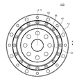
- FIG. 1 is a front view schematically showing an example of the friction transmission device 100 according to the present embodiment.
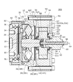
- FIG. 2 is a cross-sectional view schematically showing the friction transmission device 100. This figure shows a cross section along line AA of FIG.
- the friction transmission device 100 causes the planetary rolling elements to rotate and revolve by rotating the input orbital wheel, and the generated rotational component is transferred from the output shaft connected to the output orbital wheel to the driven device (not shown). It is configured to output.
- the friction transmission device 100 mainly includes a transmission mechanism 10, a relative position change mechanism 60, and a coupling 70.
- the transmission mechanism 10 is a mechanism that shifts the rotation input from the motor 50 and transmits it to the coupling 70.
- the relative position changing mechanism 60 is a mechanism for changing the relative position of each raceway ring of the transmission mechanism 10.
- the coupling 70 is a mechanism that absorbs the positional deviation between the output raceway ring and the output shaft of the transmission mechanism 10.
- the transmission mechanism 10 includes an input shaft 12, an input raceway ring 14, an input shaft bearing 18, a planetary rolling element 20, a first support raceway ring 26, a second support raceway ring 28, and an output raceway ring 30.
- the output shaft 32, the main bearing 34, the oil seal 36, and the first and second casings 40 and 42 are mainly provided.
- the direction along the central axis La of the input shaft 12 is referred to as "axial direction”
- the circumferential direction and radial direction of the circle centered on the central axis La are referred to as "circumferential direction” and "diameter direction", respectively. ..
- one side in the axial direction (right side in the figure) is referred to as an input side, and the other side (left side in the figure) is referred to as a non-input side.
- the input orbital ring 14, the first support orbital ring 26, the second support orbital ring 28, and the output orbital ring 30 may be simply referred to as orbital rings, and the planetary rolling element 20 may be simply referred to as a rolling element.
- the input shaft 12 rotates around the central axis La when the rotation of the motor 50 is input.
- the input shaft 12 of the present embodiment is a cylindrical member extending in the axial direction.
- An input raceway ring 14 is fixed to the outer circumference of the input shaft 12, and these rotate integrally.
- the non-input side of the input shaft 12 is connected to the inner ring of the input shaft bearing 18.
- the outer ring of the input shaft bearing 18 supports the first support raceway ring 26.
- the input shaft 12 is surrounded by the first support raceway ring 26 via a gap.
- the input shaft 12 and the first support raceway ring 26 are arranged so as to be relatively rotatable.
- the end of the input shaft 12 on the input side is connected to the relative position changing mechanism 60.
- the input shaft 12 moves in the axial direction by driving the relative position changing mechanism 60.
- the outer peripheral portion of the input shaft 12 on the input side is surrounded by the rotor 52 of the motor 50.
- the input shaft 12 is supported by the rotor 52 so as to be movable in the axial direction.
- the spline groove 12s provided on the outer peripheral surface of the input shaft 12 and the spline groove 51s provided on the inner peripheral surface of the rotor 52 mesh with each other through a gap.
- the input raceway ring 14 rotates around the central axis La as a rotation axis integrally with the input shaft 12.
- the input orbital ring 14 comes into contact with the planetary rolling element 20, and as the input orbital ring 14 rotates, the planetary rolling element 20 rotates and revolves.
- the input raceway ring 14 may be formed separately from the input shaft 12, but in this example, it is formed integrally with the input shaft 12.
- the input raceway ring 14 is a substantially disk-shaped member, and has a rolling surface 14h on the opposite side of the input raceway.
- the rolling surface 14h is a surface on which the planetary rolling element 20 rolls, and substantially makes point contact with the planetary rolling element 20.
- the rolling surface 14h is inclined with respect to the axial direction and the radial direction.
- the rolling surface 14h includes a tapered surface whose diameter is reduced toward the opposite input side.
- the rolling surface 14h may be a curved surface such as a convex surface or a concave surface, but
- the input shaft bearing 18 is provided between the end of the input shaft 12 on the opposite side of the input shaft 12 and the first support raceway ring 26.
- the input shaft bearing 18 of the present embodiment is a rolling bearing having a spherical rolling element.
- the input shaft bearing 18 has an inner ring attached to the input shaft 12 and an outer ring fixed to the first support raceway ring 26.
- the first support orbital ring 26 and the second support orbital ring 28 hold the posture and position of the planetary rolling element 20 within a certain range.
- the first support orbital ring 26 and the second support orbital ring 28 are separated from each other with the planetary rolling element 20 in between, and are arranged to face each other.
- the first support raceway ring 26 is on the opposite side of the second support raceway ring 28 and is arranged on the inner side in the radial direction.
- the first support raceway ring 26 has a ring shape that surrounds the input shaft 12 with a gap.
- the first support raceway ring 26 has a rolling surface 26h on the input side.
- the rolling surface 26h is a surface on which the planetary rolling element 20 rolls, and substantially makes point contact with the planetary rolling element 20.
- the rolling surface 26h is inclined with respect to the axial direction and the radial direction.
- the rolling surface 26h includes a tapered surface whose diameter is reduced toward the input side.
- the rolling surface 26h may be a curved surface such as a convex surface or a concave surface, but in this example, it is a flat surface.
- the first support orbital ring 26 is freely rotatable with respect to the input shaft 12 and the planetary rolling element 20, and is sometimes referred to as an idle orbital ring.
- the second support orbital ring 28 has a ring shape that surrounds the input shaft 12 and the planetary rolling element 20.
- the second support raceway ring 28 has a rolling surface 28h on the counter-input side.
- the rolling surface 28h is a surface on which the planetary rolling element 20 rolls, and substantially makes point contact with the planetary rolling element 20.
- the rolling surface 28h is inclined with respect to the axial direction and the radial direction.
- the rolling surface 28h includes a tapered surface whose diameter is reduced toward the input side.
- the rolling surface 28h may be a curved surface such as a convex surface or a concave surface, but in this example, it is a flat surface.
- the rolling surface 28h of the second support orbital ring 28 faces the rolling surface 26h of the first support orbital ring 26 with the planetary rolling element 20 interposed therebetween.
- the second support raceway ring 28 is fixed to the inner peripheral side of the second casing 42.
- the second support raceway ring 28 may be formed separately from the second casing 42, but in this example, it is integrally formed with the second casing 42.
- the output orbital ring 30 comes into contact with the planetary rolling element 20 and rotates around the central axis La as the planetary rolling element 20 rotates.
- the output raceway ring 30 is connected to the output shaft 32 via a coupling 70, and the coupling 70 and the output shaft 32 rotate as the output raceway ring 30 rotates.
- the output orbital ring 30 has a ring shape that surrounds the input shaft 12 and the planetary rolling element 20.
- the output raceway ring 30 has a rolling surface 30h on the input side.
- the rolling surface 30h is a surface on which the planetary rolling element 20 rolls, and substantially makes point contact with the planetary rolling element 20.
- the rolling surface 30h is inclined with respect to the axial direction and the radial direction.
- the rolling surface 30h includes a tapered surface whose diameter is reduced toward the opposite input side.
- the rolling surface 30h may be a curved surface such as a convex surface or a concave surface, but in this example, it is a flat surface.
- the rolling surface 30h of the output orbital ring 30 substantially opposes the rolling surface 14h of the input orbital ring 14 with the planetary rolling element 20 interposed therebetween.
- a plurality (for example, 6) of planetary rolling elements 20 are arranged at predetermined intervals in the circumferential direction.
- a retainer may be provided to hold the plurality of planetary rolling elements 20 in a desired position, but in the present embodiment, the retainer is not provided.
- a configuration without a retainer is advantageous in terms of manufacturing cost, device size, device mass, and the like.
- the number of planetary rolling elements 20 is not particularly limited, and may be less than or more than 6, but 6 to 12 are preferable.
- rolling surface 30h of the output raceway ring 30 the rolling surface 14h of the input raceway ring 14, the rolling surface 26h of the first support raceway ring 26, and the rolling surface 28h of the second support raceway ring 28 are collectively referred to.
- rolling surface Sometimes referred to simply as the "rolling surface”.
- the planetary rolling element 20 is regulated in the axial position, the radial position, and the posture by coming into contact with the four rolling surfaces.
- the shape of the planetary rolling element 20 may be any shape as long as the posture is determined by contacting the four rolling surfaces and the planet rolling body 20 can roll while contacting the four rolling surfaces.
- the planetary rolling element 20 of the present embodiment is a rotating body (hereinafter, referred to as a "prolate spheroid") obtained by rotating an ellipse or an ellipse around a short axis.
- a circle formed by passing through the center of the minor axis of the planetary rolling element 20 and intersecting the plane orthogonal to the rotation axis Lb and the outer peripheral surface of the planetary rolling element 20 is referred to as an "equator".
- the equator is a great circle formed by the intersection of a plane orthogonal to the rotation axis Lb and the outer peripheral surface of the planetary rolling element 20.
- the inclination of the rotation axis Lb of the planetary rolling element 20 with respect to the central axis La changes depending on the relative positions of the four rolling surfaces. That is, the rotation axis Lb may be parallel to the central axis La or may be inclined with respect to the central axis La.
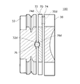
- FIG. 3 is a side view showing the periphery of the coupling 70. This figure is shown with a partial break.
- a coupling 70 is provided between the output raceway ring 30 and the output shaft 32.
- the coupling 70 absorbs the misalignment between the output raceway ring 30 and the output shaft 32.
- the coupling 70 may have any configuration as long as it can absorb the misalignment between the input side and the non-input side.
- the coupling 70 of the present embodiment is arranged on the disc portion 72, a plurality of (for example, two) first rollers 74 arranged on the input side of the disc portion 72, and the counter-input side of the disc portion 72. It has a plurality of (for example, two) second rollers 76.
- the central axes of the two first rollers 74 extend in the radial direction, and these rollers are arranged symmetrically with respect to the central axis La.
- the central axes of the two second rollers 76 extend radially, and these rollers are symmetrically arranged with the central axis La in between.
- the central axis of the first roller 74 and the central axis of the second roller 76 are orthogonal to each other.
- rollerers when the first roller 74 and the second roller 76 are collectively referred to, they are simply referred to as "rollers”.
- a first recess 74d for accommodating the first roller 74 is provided on the input side of the disk portion 72, and a second recess 76d for accommodating the second roller 76 is provided on the non-input side.
- a raceway ring side recess 30d for accommodating the first roller 74 is provided at a position corresponding to the first recess 74d.
- an output shaft side recess 32d for accommodating the second roller 76 is provided at a position corresponding to the second recess 76d.
- the first recess 74d, the second recess 76d, the raceway ring side recess 30d, and the output shaft side recess 32d are collectively referred to as a "roller recess".
- the bottom of the roller recess is composed of an inclined surface having the deepest center in the circumferential direction, and the cross section seen in the radial direction has a V shape.
- the side surface of each roller is in contact with a V-shaped inclined surface.
- the roller is supported in the roller recess with radial play.
- the roller recesses allow the rollers to rotate and limit the radial movement of the rollers to the range of the gap. By moving the rollers in the radial direction within the range of the gap, it is possible to absorb the misalignment in the radial direction. By moving the bottom of the roller recess along the side surface of the roller, misalignment in the tilt direction can be absorbed.
- the disk portion 72 functions as a spring that bends in the axial direction. Therefore, by using the disk portion 72 as a spring, the pressurization applied to each raceway ring can be adjusted. Further, when torque acts on the coupling 70, the axial load applied to the output raceway ring 30 increases due to the action of the V-shaped inclination of the bottom portion. Therefore, the coupling 70 can increase or decrease the contact load between each orbital wheel and the planetary rolling element according to the transmission torque. In this way, the coupling 70 transmits the rotation of the output raceway ring 30 to the output shaft 32 while absorbing the positional deviation (center deviation) between the output raceway ring 30 and the output shaft 32.
- the output shaft 32 is connected to the output raceway ring 30 via a coupling 70, and rotates as the output raceway ring 30 rotates.
- the output shaft 32 is sometimes referred to as an output flange.
- the output shaft 32 of the present embodiment has a substantially disk shape and is rotatably supported by the first casing 40 via the main bearing 34.
- the driven device is connected to the opposite side of the output shaft 32.
- the main bearing 34 is provided between the output shaft 32 and the first casing 40, and rotatably supports the output shaft 32 with respect to the first casing 40.
- the type of bearing is not limited, but the main bearing 34 of the present embodiment is a cross roller bearing having a cylindrical roller as a rolling element.
- the inner ring of the main bearing 34 is provided integrally with the output shaft 32, and the outer ring of the main bearing 34 is provided integrally with the first casing 40.
- the oil seal 36 is provided between the output shaft 32 and the first casing 40 on the opposite side of the main bearing 34.
- the oil seal 36 suppresses leakage of the lubricating material from the main bearing 34 and reduces the intrusion of foreign matter into the main bearing 34.
- the first and second casings 40 and 42 are hollow substantially cylindrical members and function as the outer shell of the friction transmission device 100.
- the first and second casings 40 and 42 are mainly connected to the input side of the first casing 40 and the first casing 40 that surrounds the output shaft 32, and mainly surrounds the coupling 70 and the transmission mechanism 10.
- the first casing 40 is connected to the second casing 42 by bolts B2.
- a second support raceway ring 28 is provided on the inner peripheral side of the second casing 42.
- a flange portion 42f is provided on the outer peripheral side of the second casing 42.
- the second casing 42 is connected to the motor 50 by connecting the flange portion 42f to the motor casing 54, which will be described later, with bolts B1.
- the motor 50 will be described with reference to FIG.
- the type of the motor 50 is not limited, but the motor 50 of the present embodiment is an inner rotor type brushless motor having a motor shaft 51.
- the motor 50 mainly includes a motor shaft 51, a rotor 52, a stator 53, a motor casing 54, a first cover portion 56, a second cover portion 57, and a pair of motor bearings 58.
- the motor shaft 51 is a hollow shaft having a hollow portion 51c for advancing and retreating the linear motion shaft 66, which will be described later.
- the motor shaft 51 is supported by the first cover portion 56 and the second cover portion 57 by a pair of motor bearings 58 arranged apart from each other in the axial direction.
- the rotor 52 has a main body 52b integrally formed on the outer circumference of the motor shaft 51, and a cylindrical magnet 52m fixed to the outer circumference of the main body 52b and having a predetermined magnetic pole.
- the stator 53 has a stator core 53s that faces a magnet 52m via a magnetic gap, and an armature coil 53c provided on the stator core 53s.
- the motor casing 54 is a cylindrical member fixed to the outer circumference of the stator core 53s.
- the first cover portion 56 is a disk-shaped member that closes the counter-input side of the motor casing 54.
- the second cover portion 57 is a disk-shaped member that closes the input side of the motor casing 54.
- the first cover portion 56, the motor casing 54, and the second cover portion 57 are integrated by the bolt B1 and connected to the flange portion 42f.
- the relative position changing mechanism 60 will be described with reference to FIG. As described above, the relative position changing mechanism 60 is a mechanism for changing the relative positions of the input raceway ring 14, the output raceway ring 30, the first support raceway ring 26, and the second support raceway ring 28.
- the relative position change mechanism 60 may change the relative position between one or more of these four raceway wheels and the remaining raceway rings.
- the relative position changing mechanism 60 of the present embodiment includes a moving mechanism 62 that integrally moves the input raceway ring 14 and the first support raceway ring 26 relative to each other in the axial direction.
- the moving mechanism 62 is a linear motion actuator having a linear motion shaft 66 that advances and retreats in the hollow portion 51c of the motor shaft 51, and an actuator body 64 that generates an axial driving force on the linear motion shaft 66.
- the linear motion shaft 66 has a circular rod shape extending in the axial direction. A part of the actuator main body 64 is housed in the hollow portion 51c of the motor shaft 51.
- the configuration of the moving mechanism 62 is not limited as long as it can drive the linear motion shaft 66 forward and backward.
- the linear motion shaft 66 may be driven by a stepping motor or may be driven in the axial direction by a voice coil motor or the like in a non-rotating manner.
- the moving mechanism 62 of the present embodiment converts the rotary motion into a linear motion by the ball screw mechanism, and drives the linear motion shaft 66 in the axial direction.
- the actuator body 64 is provided with an extension portion 62f that extends outward in the radial direction.
- the actuator body 64 is connected to the motor 50 by fixing the extension portion 62f to the second cover portion 57 with the bolt B3.
- a connecting hole 12h recessed on the non-input side is provided at the end of the input shaft 12 on the input side.
- the tip of the linear motion shaft 66 is housed in the connecting hole 12h.
- a connecting bearing 68 is provided between the linear motion shaft 66 and the connecting hole 12h.
- the outer ring of the connecting bearing 68 is fixed to the connecting hole 12h, and the inner ring of the connecting bearing 68 is fixed to the tip of the linear motion shaft 66.
- the input shaft 12 When the linear motion shaft 66 moves in the axial direction, the input shaft 12 also moves in the axial direction, and accordingly, the input raceway ring 14 and the first support raceway ring 26 move to the input side or the counter-input side, and these and the output raceway ring 30 And the relative relationship with the second support raceway wheel 28 is changed.
- the gear ratio Rs of the transmission mechanism 10 is changed.
- the gear ratio Rs can be changed by a simple configuration in which the input shaft 12 is moved in the axial direction. Further, since the linear motion shaft 66 is arranged in the hollow portion 51c of the motor shaft 51, the device can be miniaturized.
- FIG. 4 is an explanatory diagram illustrating the operation of the transmission mechanism 10.
- each rolling surface is drawn as a curved surface, but each rolling surface is flat in the contact region with the planetary rolling element 20.
- the planetary rolling element 20 revolves around the rotation axis Lb while rotating around the rotation axis Lb.
- the central axis La will be described below as the revolution axis.
- the contact points between the planetary rolling elements 20 and the input orbital ring 14, the first support orbital ring 26, the second support orbital ring 28, and the output orbital ring 30 are the input contact point 14c, the first support contact point 26c, and the second support.
- the contact point 28c and the output contact point 30c As shown in FIG. 4, the rotation radii of the contact points 14c, 26c, 28c, 30c are Rbg, Rbh, Rbm, Rbn, and the revolution radii of the contact points 14c, 26c, 28c, 30c are Rg, Rh, Rm, Let it be Rn.
- the gear ratio Rs is expressed by the following formula 1.
- the planetary rolling element 20 has a posture in which the input side of the rotation axis Lb approaches the central axis La.
- the attitude of the planetary rolling element 20 is such that the anti-input side of the rotation axis Lb approaches the central axis La. Be changed.
- the rotation radius and the revolution radius of each contact point are changed, and the gear ratio Rs is also changed.
- the gear ratio Rs of the transmission mechanism 10 can be changed by changing the relative position of each orbital wheel and changing the posture of the planetary rolling element 20.
- the gear ratio Rs is kept constant.
- a shaft member is provided on the planetary rolling element 20 along the rotation shaft Lb, and the shaft member is bearing. It may be provided with a configuration supported by.
- the planetary rolling element 20 is supported by the shaft member.
- the planetary rolling element 20 is supported by the input orbital ring 14, the output orbital ring 30, the first support orbital ring 26, and the second support orbital ring 28 without being supported by the shaft member.
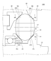
- FIG. 5 is an explanatory diagram illustrating a configuration in which the planetary rolling element 20 is supported by each orbital ring.
- This figure shows an extension of each vector in a plane including the central axis La and the rotation axis Lb.
- a quadrangle is formed by an extension of the normal vector at the contact point between the planetary rolling elements and each orbital ring.
- the quadrangle formed by the extension line is not formed, and the posture of the planetary rolling element 20 becomes unstable.
- the extension lines 14m, 26m, 28m, 30m of these normal vectors intersect each other to form a square 20s.
- the posture of the planetary rolling element 20 is uniquely determined, and the posture of the planetary rolling element 20 is maintained without being supported by the shaft member. If the quadrangle 20s is a convex quadrangle (a quadrangle having an internal angle of 180 degrees or more and having no corners), the stability of the posture is further improved.
- the area of the quadrangle 20s may be too small. If the area of the quadrangle 20s is too small, the attitude of the planetary rolling element 20 may become unstable. From the viewpoint of stabilizing the posture, the area of the quadrangle 20s is preferably 4% or more, more preferably 25% or more, and further preferably 60% or more of the cross-sectional area of the planetary rolling element 20. The area of the quadrangle 20s may be 15% or more of the cross-sectional area of the planetary rolling element 20.
- the directions of the normal vectors of the opposite sides of the quadrangle 20s may be the same. If the directions of the normal vectors of the opposite sides of the quadrangle 20s are the same, the attitude of the planetary rolling element 20 may become unstable. Therefore, in the present embodiment, the normal vectors of the opposite sides of the quadrangle are configured to have opposite directions. Specifically, the normal vector 14v and the normal vector 30v are in opposite directions, and the normal vector 26v and the normal vector 28v are in opposite directions. In this case, since the position and orientation of the planetary rolling elements 20 are constrained by each orbital ring, the attitude of the planetary rolling elements 20 is further stabilized. Further, when both of the normal vectors of two adjacent sides of the quadrangle 20s are directed toward the corner or away from the corner, the posture is further stable.
- each orbital ring and the planetary rolling element 20 are both flat surfaces, the contact area will increase and mechanical loss will increase, and if these contact surfaces are both curved surfaces, the manufacturing effort will increase. Therefore, in the present embodiment, with respect to the contact surfaces of the input contact point 14c, the first support contact point 26c, the second support contact point 28c, and the output contact point 30c, each orbital ring is a flat surface, and the planetary rolling elements 20 The surface facing each raceway ring is a curved surface. In this case, the increase in mechanical loss can be suppressed, and the manufacturing of the member becomes easy.
- the curved surface of the planetary rolling element 20 is not limited, but in this example, the curved surface has the contour of an involute curve.
- the friction transmission device 100 since the quadrangle is formed by the extension line of the normal vector at the contact point between the planetary rolling element 20 and each orbital ring, the quadrangle is formed as compared with the case where the quadrangle is not formed by the extension line. , The posture of the planetary rolling element 20 is stable. Since the configuration for maintaining the posture of the planetary rolling element 20 is simple, the manufacturing cost can be reduced.
- the planetary rolling element 20 is supported by the input orbital ring 14, the output orbital ring 30, the first support orbital ring 26, and the second support orbital ring 28 without being supported by the shaft member.
- the manufacturing cost of the shaft member and its peripheral members can be reduced.
- the friction transmission device 100 according to the second embodiment of the present disclosure will be described with reference to FIGS. 6 to 9.
- the same or equivalent components and members as those of the first embodiment are designated by the same reference numerals.
- the description overlapping with the first embodiment will be omitted as appropriate, and the configuration different from the first embodiment will be mainly described.
- the friction transmission device 100 of the present embodiment is different from the first embodiment in that the shape of the rolling element and the shape of the contact portion between the rolling element and each raceway ring are different, and the other configurations are the same. .. Therefore, these differences will be focused on.
- FIG. 6 is a cross-sectional view showing the periphery of the planetary rolling element 20 of the friction transmission device 100 of the embodiment.
- the contact portion with the orbital ring is an arc.
- the curved surfaces of the contact portions with the orbital rings 14, 26, 28 and the orbital rings 30 have the contour of an arc curve.
- the contour of the orbital plane of the planetary rolling element 20 is an arc, it becomes easy to process the rolling element, measure the contour after processing, and manage them, and in terms of cost reduction and quality stabilization. It is advantageous.
- the position of the contact point of the rolling element will be described with reference to FIG. As shown by the broken line in FIG. 6, when the positions of the contact points with the inner orbital ring and the contact points with the outer orbital ring in the planetary rolling element 20 overlap, stress is concentrated there and fatigue is accumulated. However, the life of the planetary rolling element 20 may be shortened. Therefore, in the present embodiment, the contact points of the inner orbital ring and the outer orbital ring arranged at overlapping positions when viewed from the radial direction with the planetary rolling elements 20 are displaced in the axial direction.
- the input orbital ring 14 and the second support orbital ring 28 are arranged at overlapping positions when viewed from the radial direction, and the contact point 14c between the planetary rolling element 20 and the input orbital ring 14
- the contact point 28c between the planetary rolling element 20 and the second support orbital ring 28 is displaced in the axial direction.
- the contact angle ⁇ 1 of the rolling surface 14h (shown by the solid line in FIG. 6) of the input raceway ring 14 is different from the contact angle ⁇ 2 of the rolling surface 28h of the second support raceway ring 28. It may be configured.
- the output orbital ring 30 and the first support orbital ring 26 are arranged at overlapping positions when viewed from the radial direction, and the contact point 30c between the planetary rolling element 20 and the output orbital ring 30 and the planetary rolling element 20 and the first support are arranged. It is axially deviated from the contact point 26c of the raceway ring 26.
- the contact angle ⁇ 3 of the rolling surface 26h (shown by the solid line in FIG. 6) of the first support raceway ring 26 is different from the contact angle ⁇ 4 of the rolling surface 30h of the output raceway ring 30. It may be configured.
- raceway surfaces on the inner ring side and the outer ring side have different contact angles, and the contact point of the raceway ring on the inner ring side and the contact point of the raceway ring on the outer ring side are shifted in the axial direction to stress the rolling elements. Can be dispersed to reduce the accumulation of fatigue and extend the life.
- the planetary rolling element 20 of the present embodiment has a recess 22 at the center.
- the recess 22 may be a bottomed hole, but the recess 22 in this example is a through hole.
- FIG. 7 is a schematic view showing the relationship between the raceway ring and the rolling element.
- the raceway ring and the rolling element are represented in two dimensions for ease of understanding.
- the radial outer raceway ring is shown as an outer ring
- the radial inner raceway ring is shown as an inner ring in a circle. All rolling elements (rolling bodies 1 to 6) are in contact with the outer ring and the inner ring.
- the diameter of the outer ring is indicated by D1
- the center position of the input shaft 12 is indicated by P0.
- FIG. 8 is a diagram conceptually showing the effect of the error in the diameter of the rolling element on the center position of the input shaft 12.
- the contact point between the rolling element 1 and the outer ring is indicated by P1
- the contact point between the rolling element 4 on the opposite side of the rolling element 1 and the outer ring is indicated by P4
- the rolling elements 1 to 6 all have the same diameter.
- the center position of the input shaft 12 is indicated by P0.
- the center position of the input shaft 12 deviates from P0 as shown by P0d. That is, the amount of deviation of the center position of the input shaft 12 can be calculated by the geometric relationship shown in FIG.
- FIG. 9 is a diagram showing the relationship between the number of rolling elements and the amount of deviation of the center position of the input shaft 12.
- This figure shows the result of calculating the deviation amount of the center position of the input shaft 12 from the number of rolling elements using the geometric relationship of FIG.
- the horizontal axis represents the number of rolling elements
- the vertical axis represents a relative value obtained by dividing the amount of deviation of the center position of the input shaft 12 by a predetermined unit amount. From the examination of FIG. 9, it was found that when the number of rolling elements is an odd number, the amount of deviation of the center position of the input shaft 12 due to the variation in the diameter of the rolling elements is smaller than when the number of rolling elements is an even number. Based on this result, the present embodiment has an odd number (for example, 7) of planetary rolling elements 20 to reduce the influence of variation in the diameter of the rolling elements.
- the present embodiment is easy to manufacture because the contact portion of the planetary rolling element is an arc. Further, in the present embodiment, since the contact points inside and outside are displaced in the axial direction, the stress of the rolling element can be dispersed. Further, since the present embodiment has a recess in the central portion, the influence of dimensional variation of the rolling element can be suppressed. Further, since the present embodiment has an odd number of rolling elements, the influence of variation in the diameter of the rolling elements can be suppressed.
- FIG. 10 is a cross-sectional view showing the friction transmission device 200 according to the first modification, and corresponds to FIG.
- This modification is different from the embodiment mainly in that the shape of each orbital ring is different from that of the planetary rolling element 20, and the other configurations are the same. Therefore, different configurations will be described.
- the planetary rolling element 20 of this modification is a rotating body obtained by rotating a rectangle having an angle R.
- the planetary rolling element 20 has a curved surface portion 20h formed by rotating the angle R.
- the rolling surfaces 14h, 26h, 28h, and 30h are in contact with the curved surface portion 20h.
- the friction transmission device 200 operates in the same manner as in the embodiment.
- FIG. 11 is a cross-sectional view showing the friction transmission device 300 of the second modification, and corresponds to FIG.
- This modification is different from the embodiment mainly in that the shape of each orbital ring is different from that of the planetary rolling element 20, and the other configurations are the same. Therefore, different configurations will be described.
- the planetary rolling element 20 of this modification is a rotating body obtained by rotating a figure having a curved portion in the vicinity of the intersection of two sides on the apex side of the triangle around the other one side.
- the planetary rolling element 20 has a substantially rhombic cross section.
- the planetary rolling element 20 has a curved surface portion 20h formed by rotating this curved portion.
- Each orbital ring has a shape in contact with the curved surface portion 20h of the planetary rolling element 20.
- the rolling surfaces 14h, 26h, 28h, and 30h are in contact with the curved surface portion 20h.
- the friction transmission device 300 operates in the same manner as in the embodiment and has the same characteristics.
- FIG. 12 is a cross-sectional view showing the friction transmission device 400 of the third modification, and corresponds to FIG.
- This modification is different from the embodiment mainly in that the shape of each orbital ring is different from that of the planetary rolling element 20, and the other configurations are the same. Therefore, different configurations will be described.
- the planetary rolling element 20 of this modified example consists of a semicircle and a pentagon protruding from the center of the arc of the semicircle to the opposite side of the string of the semicircle, and is curved on two sides on the apex side of this semicircle. It is a rotating body obtained by rotating a figure having a part around the semicircular string.
- the planetary rolling element 20 has a circumferential convex portion 20c in which the equator protrudes in a convex shape.
- the planetary rolling element 20 has a curved surface portion 20h formed by rotating a pentagonal curved portion.
- the rolling surfaces 14h and 26h are in contact with the region corresponding to the arc of the semicircle, and the rolling surfaces 28h and 30h are in contact with the curved surface portion 20h.
- the friction transmission device 400 operates in the same manner as in the embodiment and has the same characteristics.
- FIG. 13 is a cross-sectional view showing the friction transmission device 500 of the fourth modification, and corresponds to FIG.
- This modification is different from the embodiment mainly in that the shapes of the planetary rolling element 20, each orbital ring, the output orbital ring 30, the disk portion 72, and the output shaft 32 are different, and other configurations are different. The same is true. Therefore, different configurations will be described.
- the planetary rolling element 20 of this modification is obtained by denting from the center of the arc of the semicircle toward the chord of the semicircle, and rotating a figure having a curved portion in the dent around the chord of the semicircle. It is a rotating body.
- the planetary rolling element 20 has a circumferential recess 20d in which the equator of the sphere is recessed in a circumferential shape, and a curved surface portion 20h is formed in the peripheral recess 20d.
- the rolling surfaces 14h and 26h are in contact with the region corresponding to the semicircular arc of the planetary rolling element 20, and the rolling surfaces 28h and 30h are in contact with the curved surface portion 20h.
- the first roller 74 and the first recess 74d are provided on the opposite side of the disc portion 72, and the second roller 76 and the second recess 76d are provided on the input side of the disc portion 72.
- the output raceway ring 30 has a disc-shaped portion 30b arranged on the opposite side of the disc portion 72 via a gap, and a tubular extending portion 30e extending from the outer circumference of the disc-shaped portion 30b to the input side. ..
- a rolling surface 30h is provided at the end of the tubular extending portion 30e on the input side, and a raceway ring side recess 30d is provided on the input side of the disc-shaped portion 30b.
- the output shaft 32 has an output shaft main body 32b, a tubular extension 32e extending from the input side end surface of the output shaft main body 32b to the input side, and a tubular extension 32e in the radial direction from the input side end. It has a flange portion 32f overhanging.
- the flange portion 32f has a disk shape that is arranged on the input side of the disk portion 72 with a gap.
- An output shaft side recess 32d is provided on the opposite side of the flange portion 32f.
- the friction transmission device 500 operates in the same manner as in the embodiment and has the same characteristics.
- FIG. 14 is a cross-sectional view showing the friction transmission device 600 of the fifth modification, and corresponds to FIG.
- This modified example is different from the fourth modified example mainly in that the shape of each orbital ring is different from that of the planetary rolling element 20, and the other configurations are the same. Therefore, different configurations will be described.
- the planetary rolling element 20 of this modification is a rotating body obtained by rotating a rectangle having a V-shaped recessed side around the side opposite to the recessed side.
- the planetary rolling element 20 has a circumferential recess 20d in which the equator is recessed in a circumferential shape, and a curved surface portion 20h is formed in the peripheral recess 20d.
- the rolling surfaces 14h, 26h, 28h, and 30h are in contact with the curved surface portion 20h.
- the friction transmission device 600 operates in the same manner as in the embodiment and has the same characteristics.
- first support raceway ring 26 rotates freely and the second support raceway ring 28 stands still, but the present invention is not limited to this.
- the first support raceway ring 26 may be stationary and the second support raceway ring 28 may rotate freely.
- the input orbital ring 14 is arranged radially inside and the output orbital ring 30 is arranged radially outside with respect to the rotation axis of the planetary rolling element 20.
- the present invention is not limited to this, and the input raceway ring 14 may be arranged on the outside and the output raceway ring 30 may be arranged on the inside, both may be arranged on the inside, or both may be arranged on the outside. May be good.
- the present invention can be used as a friction transmission device.
- transmission mechanism 12 input shaft, 14 input raceway ring, 18 input shaft bearing, 20 planetary rolling elements, 26 first support raceway ring, 28 second support raceway wheel, 30 output raceway wheel, 32 output shaft, 34 main bearing, 40 1st casing, 42 2nd casing, 50 motor, 60 relative position change mechanism, 62 movement mechanism, 66 linear motion shaft, 70 coupling, 100 friction transmission device.
Landscapes
- Engineering & Computer Science (AREA)
- General Engineering & Computer Science (AREA)
- Mechanical Engineering (AREA)
- Power Engineering (AREA)
- Friction Gearing (AREA)
Abstract
摩擦伝動装置100は、入力軌道輪14と、入力軌道輪14の回転軸周りに配置され入力軌道輪14に接触する遊星転動体20と、遊星転動体20と接触し出力軸32と連結される出力軌道輪30と、遊星転動体20に接触する第1支持軌道輪26および第2支持軌道輪28と、を備えた摩擦伝動装置であって、遊星転動体20と各軌道輪との接触点における法線ベクトルの延長線により四角形が形成されるように構成されている。
Description
本発明は、摩擦伝動装置に関する。
IVT(Infinitely Variable Transmission)と呼ばれ、無限大の変速比が可能な無段変速機が知られている。例えば、特許文献1には、軸線周りに角度を付けて配置された複数の遊星アセンブリを有する変速機が記載されている。この変速機は、遊星アセンブリに接する回転不能な第1の牽引リングと、遊星アセンブリに接して動力を伝達する第2の牽引リングと、遊星アセンブリの軸心の一端に結合された第1のキャリア部材と、遊星アセンブリの軸心の他端に結合された第2のキャリア部材と、遊星アセンブリの傾斜角を調整するシフト制御機構とを備える。
変速機は、ロボットや自走台車など多くのアプリケーションで使用されることが期待される。変速機が多くのアプリケーションで使用されるためには、その製造コストを削減することが望ましい。しかし、特許文献1に記載の変速機は、遊星アセンブリの自転を支持するために多数の部材が複雑に組み合わされているため、製造コストを削減することが難しい。
本発明の目的は、このような課題に鑑みてなされたもので、製造コストを削減することが可能な摩擦伝動装置を提供することにある。
上記課題を解決するために、本発明のある態様の摩擦伝動装置は、入力軌道輪と、入力軌道輪の回転軸周りに配置され入力軌道輪に接触する遊星転動体と、遊星転動体と接触し出力軸と連結される出力軌道輪と、遊星転動体に接触する第1支持軌道輪および第2支持軌道輪と、を備えた摩擦伝動装置であって、遊星転動体と各軌道輪との接触点における法線ベクトルの延長線により四角形が形成されるように構成されている。
なお、以上の構成要素の任意の組み合わせや、本発明の構成要素や表現を方法、システムなどの間で相互に置換したものもまた、本発明の態様として有効である。
本発明によれば、製造コストを削減することが可能な摩擦伝動装置を提供できる。
以下、本発明を好適な実施形態をもとに各図面を参照しながら説明する。実施形態および変形例では、同一または同等の構成要素、部材には、同一の符号を付するものとし、適宜重複した説明は省略する。また、各図面における部材の寸法は、理解を容易にするために適宜拡大、縮小して示される。また、各図面において実施形態を説明する上で重要ではない部材の一部は省略して表示する。
また、第1、第2などの序数を含む用語は多様な構成要素を説明するために用いられるが、この用語は一つの構成要素を他の構成要素から区別する目的でのみ用いられ、この用語によって構成要素が限定されるものではない。
[第1実施形態]
図1を参照して、本開示の第1実施形態に係る摩擦伝動装置100の構成を説明する。図1は、本実施形態に係る摩擦伝動装置100の一例を概略的に示す正面図である。図2は、摩擦伝動装置100を概略的に示す断面図である。この図は、図1のA-A線に沿った断面を示している。
図1を参照して、本開示の第1実施形態に係る摩擦伝動装置100の構成を説明する。図1は、本実施形態に係る摩擦伝動装置100の一例を概略的に示す正面図である。図2は、摩擦伝動装置100を概略的に示す断面図である。この図は、図1のA-A線に沿った断面を示している。
摩擦伝動装置100は、入力軌道輪を回転させることにより遊星転動体に自転と公転とを生じさせ、その生じた回転成分を出力軌道輪と連結される出力軸から被駆動装置(不図示)に出力するように構成される。
摩擦伝動装置100は、主に、伝達機構10と、相対位置変更機構60と、カップリング70とを含む。伝達機構10は、モータ50から入力された回転を変速してカップリング70に伝達する機構である。相対位置変更機構60は、伝達機構10の各軌道輪の相対位置を変更する機構である。カップリング70は、伝達機構10の出力軌道輪と出力軸の間の位置ずれを吸収する機構である。
(伝達機構)
伝達機構10を説明する。伝達機構10は、入力軸12と、入力軌道輪14と、入力軸軸受18と、遊星転動体20と、第1支持軌道輪26と、第2支持軌道輪28と、出力軌道輪30と、出力軸32と、主軸受34と、オイルシール36と、第1、第2ケーシング40、42とを主に備える。以下、入力軸12の中心軸線Laに沿った方向を「軸方向」といい、その中心軸線Laを中心とする円の円周方向、半径方向をそれぞれ「周方向」、「径方向」とする。また、以下、便宜的に、軸方向の一方側(図中右側)を入力側といい、他方側(図中左側)を反入力側という。入力軌道輪14、第1支持軌道輪26、第2支持軌道輪28および出力軌道輪30を単に軌道輪ということがあり、遊星転動体20を単に転動体ということがある。
伝達機構10を説明する。伝達機構10は、入力軸12と、入力軌道輪14と、入力軸軸受18と、遊星転動体20と、第1支持軌道輪26と、第2支持軌道輪28と、出力軌道輪30と、出力軸32と、主軸受34と、オイルシール36と、第1、第2ケーシング40、42とを主に備える。以下、入力軸12の中心軸線Laに沿った方向を「軸方向」といい、その中心軸線Laを中心とする円の円周方向、半径方向をそれぞれ「周方向」、「径方向」とする。また、以下、便宜的に、軸方向の一方側(図中右側)を入力側といい、他方側(図中左側)を反入力側という。入力軌道輪14、第1支持軌道輪26、第2支持軌道輪28および出力軌道輪30を単に軌道輪ということがあり、遊星転動体20を単に転動体ということがある。
入力軸12は、モータ50の回転が入力されると、中心軸線La周りに回転する。本実施形態の入力軸12は、軸方向に延びる円筒状の部材である。入力軸12の外周には入力軌道輪14が固定されており、これらは一体的に回転する。入力軸12の反入力側は入力軸軸受18の内輪に接続されている。入力軸軸受18の外輪は第1支持軌道輪26を支持する。入力軸12は、隙間を介して第1支持軌道輪26に環囲される。入力軸12と第1支持軌道輪26とは、相対的に回転可能に配置される。
入力軸12の入力側の端部は、相対位置変更機構60に連結される。入力軸12は、相対位置変更機構60の駆動により軸方向に移動する。入力軸12の入力側の外周部は、モータ50の回転子52に環囲される。入力軸12は、回転子52によって軸方向に移動可能に支持される。入力軸12の外周面に設けられたスプライン溝12sと、回転子52の内周面に設けられたスプライン溝51sとは、隙間を介して噛み合っている。
入力軌道輪14は、入力軸12と一体的に中心軸線Laを回転軸としてその周りに回転する。入力軌道輪14は、遊星転動体20と接触し、入力軌道輪14が回転するにつれて遊星転動体20に自転と公転とを生じさせる。入力軌道輪14は、入力軸12と別体に形成されてもよいが、この例では、入力軸12と一体的に形成されている。入力軌道輪14は、略円板状の部材で、反入力側に転動面14hを有する。転動面14hは、遊星転動体20が転動する面であり、遊星転動体20と実質的に点接触する。転動面14hは、軸方向および径方向に対して傾斜している。転動面14hは、反入力側に向かって縮径するテーパー面を含む。転動面14hは、凸面や凹面などの曲面であってもよいが、この例では平坦面である。
入力軸軸受18は、入力軸12の反入力側の端部と第1支持軌道輪26との間に設けられる。軸受の種類に限定はないが、本実施形態の入力軸軸受18は、球状の転動体を有する転がり軸受である。入力軸軸受18は、入力軸12に取り付けられた内輪と、第1支持軌道輪26に固定された外輪とを有する。
第1支持軌道輪26および第2支持軌道輪28は、遊星転動体20の姿勢および位置を一定の範囲に保持する。第1支持軌道輪26と、第2支持軌道輪28とは、遊星転動体20を挟んで離隔され、対向配置される。第1支持軌道輪26は、第2支持軌道輪28の反入力側であって、径方向内側に配置される。
第1支持軌道輪26は、入力軸12を隙間を介して環囲するリング形状を有する。第1支持軌道輪26は、入力側に転動面26hを有する。転動面26hは、遊星転動体20が転動する面であり、遊星転動体20と実質的に点接触する。転動面26hは、軸方向および径方向に対して傾斜している。転動面26hは、入力側に向かって縮径するテーパー面を含む。転動面26hは、凸面や凹面などの曲面であってもよいが、この例では平坦面である。第1支持軌道輪26は、入力軸12および遊星転動体20に対して自由に回転可能であり、遊転軌道輪と称されることがある。
第2支持軌道輪28は、入力軸12および遊星転動体20を環囲するリング形状を有する。第2支持軌道輪28は、反入力側に転動面28hを有する。転動面28hは、遊星転動体20が転動する面であり、遊星転動体20と実質的に点接触する。転動面28hは、軸方向および径方向に対して傾斜している。転動面28hは、入力側に向かって縮径するテーパー面を含む。転動面28hは、凸面や凹面などの曲面であってもよいが、この例では平坦面である。第2支持軌道輪28の転動面28hは、遊星転動体20を挟んで、第1支持軌道輪26の転動面26hと略対向する。
第2支持軌道輪28は、第2ケーシング42の内周側に固定される。第2支持軌道輪28は、第2ケーシング42と別体に形成されてもよいが、この例では、第2ケーシング42と一体的に形成されている。
出力軌道輪30は、遊星転動体20と接触し、遊星転動体20が回転するにつれて中心軸線La周りに回転する。出力軌道輪30は、カップリング70を介して出力軸32と連結されており、出力軌道輪30が回転するにつれてカップリング70および出力軸32が回転する。
出力軌道輪30は、入力軸12および遊星転動体20を環囲するリング形状を有する。出力軌道輪30は、入力側に転動面30hを有する。転動面30hは、遊星転動体20が転動する面であり、遊星転動体20と実質的に点接触する。転動面30hは、軸方向および径方向に対して傾斜している。転動面30hは、反入力側に向かって縮径するテーパー面を含む。転動面30hは、凸面や凹面などの曲面であってもよいが、この例では平坦面である。出力軌道輪30の転動面30hは、遊星転動体20を挟んで、入力軌道輪14の転動面14hと略対向する。
遊星転動体20は、周方向に所定の間隔で複数(例えば、6個)配置される。複数の遊星転動体20を所望の位置に保持するためにリテーナを備えてもよいが、本実施形態では、リテーナを備えていない。リテーナを有しない構成は、製造コスト、装置の大きさ、装置の質量等の点で有利である。なお、遊星転動体20の個数は特に限定されず、6個より少なくても多くてもよいが、6~12個が好ましい。
以下、出力軌道輪30の転動面30h、入力軌道輪14の転動面14h、第1支持軌道輪26の転動面26hおよび第2支持軌道輪28の転動面28hを総称するときは単に「転動面」ということがある。
遊星転動体20は、4つの転動面に接触することにより軸方向位置、径方向位置および姿勢が規制される。遊星転動体20の形状は、4つの転動面に接触することにより姿勢が決定され、4つの転動面に接触しながら転動可能である限り、どのような形状であってもよい。本実施形態の遊星転動体20は、短軸を中心として楕円または長円を回転させることにより得られる回転体(以下、「長球」という)である。また、本明細書では、遊星転動体20の短軸の中心を通り、自転軸Lbに直交する平面と遊星転動体20の外周面とが交わってできる円を「赤道」という。この例では、赤道は、自転軸Lbに直交する平面と遊星転動体20の外周面とが交わってできる大円である。
遊星転動体20の自転軸Lbの中心軸線Laに対する傾斜は、4つの転動面の相対位置によって変化する。つまり、自転軸Lbは、中心軸線Laと平行な場合と、中心軸線Laに対して傾斜する場合とがある。
遊星転動体20の自転軸Lbが中心軸線Laと平行な状態で、遊星転動体20の径方向寸法に対する軸方向寸法の比率Ra(=軸方向寸法/径方向寸法)を説明する。比率Raが大きいと、遊星転動体20が本来の自転軸Lbに直交する疑似自転軸を中心に回転する現象が発生する可能性がある。この現象を抑える観点から、比率Raは1以下が好ましく、0.8以下がより好ましく、0.6以下がさらに好ましい。比率Raは0.1以上にされてもよい。
図3も参照して、カップリング70を説明する。図3は、カップリング70の周辺を示す側面図である。この図は一部を破断して示している。出力軌道輪30と出力軸32との間にはカップリング70が設けられる。カップリング70は、出力軌道輪30と出力軸32の間の位置ずれを吸収する。カップリング70は、入力側と反入力側との芯ずれを吸収可能である限り、どのような構成であってもよい。
本実施形態のカップリング70は、円板部72と、円板部72の入力側に配置された複数(例えば2個)の第1ローラ74と、円板部72の反入力側に配置された複数(例えば2個)の第2ローラ76とを有する。2つの第1ローラ74の中心軸は径方向に延びており、これらのローラは中心軸線Laを挟んで対称に配置されている。2つの第2ローラ76の中心軸は径方向に延びており、これらのローラは中心軸線La挟んで対称に配置されている。第1ローラ74の中心軸と第2ローラ76の中心軸とは互いに直交する。以下、第1ローラ74と、第2ローラ76とを総称するときは単に「ローラ」という。
円板部72の入力側には、第1ローラ74を収容する第1凹部74dが設けられ、反入力側には、第2ローラ76を収容する第2凹部76dが設けられる。出力軌道輪30の反入力側には、第1凹部74dに対応する位置に、第1ローラ74を収容する軌道輪側凹部30dが設けられる。出力軸32の入力側には、第2凹部76dに対応する位置に、第2ローラ76を収容する出力軸側凹部32dが設けられる。以下、第1凹部74d、第2凹部76d、軌道輪側凹部30dおよび出力軸側凹部32dを総称するときは「ローラ凹部」という。
図3に示すように、ローラ凹部の底部は、周方向の中央が最も深くなる傾斜面で構成されており、径方向に見た断面はV字状を呈する。各ローラの側面はV字状の傾斜面に接触している。ローラはローラ凹部に径方向の遊びをもって支持される。ローラ凹部は、ローラの回転を許容し、ローラの径方向の移動を隙間の範囲に制限している。ローラが隙間の範囲で径方向に移動することにより、径方向のミスアライメントを吸収できる。ローラ凹部の底部がローラの側面に沿って移動することにより、傾斜方向のミスアライメントを吸収できる。
円板部72は、軸方向に撓むばねとして機能する。このため、円板部72をばねとして利用することにより、各軌道輪にかかる与圧を調整できる。また、カップリング70にトルクが作用すると、底部のV字状の傾斜の作用により出力軌道輪30に加わるアキシアル荷重が増加する。このため、カップリング70は、伝達トルクに応じて、各軌道輪と遊星転動体との間の接触荷重を増減できる。このように、カップリング70は、出力軌道輪30と出力軸32との位置ずれ(芯ずれ)を吸収しつつ、出力軌道輪30の回転を出力軸32に伝達する。
出力軸32は、カップリング70を介して出力軌道輪30と連結されており、出力軌道輪30が回転するにつれて回転する。出力軸32は、出力フランジと称されることがある。本実施形態の出力軸32は、略円板状を有し、主軸受34を介して第1ケーシング40に回転可能に支持される。出力軸32の反入力側に被駆動装置が連結される。
図2に示すように、主軸受34は、出力軸32と第1ケーシング40との間に設けられ、出力軸32を第1ケーシング40に対して回転可能に支持する。軸受の種類に限定はないが、本実施形態の主軸受34は、円筒形のコロを転動体とするクロスローラベアリングである。主軸受34の内輪は、出力軸32と一体に設けられ、主軸受34の外輪は、第1ケーシング40と一体に設けられている。
図2に示すように、オイルシール36は、主軸受34の反入力側において出力軸32と第1ケーシング40との間に設けられる。オイルシール36は、主軸受34からの潤滑材の漏れ出しを抑制し、主軸受34への異物の侵入を低減する。
図2に示すように、第1、第2ケーシング40、42は、中空の略円筒状の部材で、摩擦伝動装置100の外殻として機能する。第1、第2ケーシング40、42は、主に出力軸32を環囲する第1ケーシング40と、第1ケーシング40の入力側に連結され、主にカップリング70および伝達機構10を環囲する第2ケーシング42とを含む。第1ケーシング40は、第2ケーシング42にボルトB2によって連結される。第2ケーシング42の内周側には第2支持軌道輪28が設けられている。第2ケーシング42の外周側にはフランジ部42fが設けられている。第2ケーシング42は、フランジ部42fが後述するモータケーシング54にボルトB1で連結されることによって、モータ50と接続される。
図2を参照して、モータ50を説明する。モータ50の種類に限定はないが、本実施形態のモータ50は、モータ軸51を有するインナーロータ型ブラシレスモータである。モータ50は、モータ軸51と、回転子52と、固定子53と、モータケーシング54と、第1カバー部56と、第2カバー部57と、一対のモータ軸受58とを主に含む。モータ軸51は、後述する直動軸66が進退するための中空部51cを有する中空軸である。モータ軸51は、軸方向に離れた配置された一対のモータ軸受58によって、第1カバー部56および第2カバー部57に支持される。回転子52は、モータ軸51の外周に一体的に形成された本体部52bと、本体部52bの外周に固定され、所定の磁極を有する円筒状のマグネット52mとを有する。
固定子53は、マグネット52mを磁気的空隙を介して対向するステータコア53sと、ステータコア53sに設けられる電機子コイル53cとを有する。モータケーシング54は、ステータコア53sの外周に固定される円筒部材である。第1カバー部56は、モータケーシング54の反入力側を塞ぐ円板状の部材である。第2カバー部57は、モータケーシング54の入力側を塞ぐ円板状の部材である。第1カバー部56、モータケーシング54および第2カバー部57は、ボルトB1によって一体化されるとともに、フランジ部42fに連結される
図2を参照して、相対位置変更機構60を説明する。上述したように、相対位置変更機構60は、入力軌道輪14、出力軌道輪30、第1支持軌道輪26および第2支持軌道輪28の相対位置を変更する機構である。相対位置変更機構60は、これら4つの軌道輪の1つ以上の軌道輪と残りの軌道輪との間の相対位置を変更するものであればよい。本実施形態の相対位置変更機構60は、入力軌道輪14および第1支持軌道輪26を一体的に軸方向に相対移動させる移動機構62を有する。
移動機構62は、モータ軸51の中空部51c内で進退する直動軸66と、直動軸66に軸方向の駆動力を発生させるアクチュエータ本体64とを有する直動アクチュエータである。直動軸66は、軸方向に延びる円形の棒形状を有する。アクチュエータ本体64の一部は、モータ軸51の中空部51cに収納される。移動機構62は、直動軸66を進退駆動可能なものであれば構成に限定はない。例えば、直動軸66は、ステッピングモータにより駆動されてもよいし、ボイスコイルモータなどにより非回転で軸方向に駆動されてもよい。本実施形態の移動機構62は、ボールねじ機構により回転運動を直線運動に変換し、直動軸66を軸方向に駆動する。
アクチュエータ本体64には径方向で外側に延出する延出部62fが設けられる。延出部62fがボルトB3で第2カバー部57に固定されることにより、アクチュエータ本体64は、モータ50に連結される。
入力軸12の入力側の端部には、反入力側に凹んだ連結孔12hが設けられる。直動軸66の先端は連結孔12hに収容される。直動軸66と連結孔12hの間には連結軸受68が設けられる。連結軸受68の外輪は連結孔12hに固定され、連結軸受68の内輪は直動軸66の先端に固定される。この構成により、入力軸12と直動軸66とは互いに回転可能に連結される。なお、直動軸66が非回転で移動する場合は、直動軸66と入力軸12とは、連結軸受68を介さずに連結されてもよい。
直動軸66が軸方向に移動すると入力軸12も軸方向に移動し、これにつれて入力軌道輪14および第1支持軌道輪26が入力側または反入力側に移動し、これらと出力軌道輪30および第2支持軌道輪28との相対関係が変更される。これらの相対関係が変更されることにより、伝達機構10の変速比Rsが変更される。このように、本実施形態においては、入力軸12を軸方向に移動させるという簡易な構成で変速比Rsを変更できる。また、直動軸66をモータ軸51の中空部51cに配置させているため、装置の小型化が可能となる。
図4を参照して、伝達機構10の動作を説明する。図4は、伝達機構10の動作を説明する説明図である。この図では、各転動面を曲面状に描いているが、各転動面は、遊星転動体20との接触領域において平坦である。入力軌道輪14が回転すると、遊星転動体20が自転軸Lb周りに自転しながら公転軸周りに公転する。この例では、遊星転動体20の公転軸は中心軸線Laと一致しているため、以下では中心軸線Laを公転軸として説明する。
遊星転動体20と、入力軌道輪14、第1支持軌道輪26、第2支持軌道輪28および出力軌道輪30との接触点を、入力接触点14c、第1支持接触点26c、第2支持接触点28cおよび出力接触点30cとする。図4に示すように、接触点14c、26c、28c、30cの自転半径を、Rbg、Rbh、Rbm、Rbnとし、接触点14c、26c、28c、30cの公転半径を、Rg、Rh、Rm、Rnとする。
第1支持軌道輪26が自由回転し、第2支持軌道輪28が非回転で静止している場合、入力軌道輪14の回転速度ω1に対する出力軌道輪30の回転速度ω2の比(以下、「変速比Rs」という)は、下記の数式1によって示される。

図4の状態では、遊星転動体20は、自転軸Lbの入力側が中心軸線Laに近づく姿勢を有する。相対位置変更機構60により入力軌道輪14および第1支持軌道輪26の位置が入力側に変更されると、遊星転動体20の姿勢は、自転軸Lbの反入力側が中心軸線Laに近づくように変更される。この結果、各接触点の自転半径および公転半径が変更され、変速比Rsも変更される。このように、各軌道輪の相対位置を変更して遊星転動体20の姿勢を変更することによって伝達機構10の変速比Rsを変更できる。逆にいうと、遊星転動体20の姿勢を一定に支持することにより、変速比Rsは一定に保たれる。
遊星転動体20の姿勢の変動を抑制するために、一例として、特許文献1に記載の変速機のように、自転軸Lbに沿って遊星転動体20に軸部材を設け、その軸部材を軸受で支持する構成を備えてもよい。この場合、遊星転動体20は、軸部材により支持される。本実施形態では、遊星転動体20は、軸部材により支持されることなく、入力軌道輪14、出力軌道輪30、第1支持軌道輪26および第2支持軌道輪28により支持される。
図5を参照して、各軌道輪により遊星転動体20を支持する構成を説明する。図5は、遊星転動体20が各軌道輪により支持される構成を説明する説明図である。この図は、中心軸線Laおよび自転軸Lbを含む平面における各ベクトルの延長線を示している。図5に示すように、本実施形態では、遊星転動体と各軌道輪との接触点における法線ベクトルの延長線により四角形が形成される。遊星転動体20の形状によっては、延長線による四角形が形成されず、遊星転動体20の姿勢が不安定になる。
図5に示すように、入力接触点14cにおける法線ベクトル14vと、第1支持接触点26cにおける法線ベクトル26vと、第2支持接触点28cにおける法線ベクトル28vと、出力接触点30cにおける法線ベクトル30vについて、これらの法線ベクトルの延長線14m、26m、28m、30mは互いに交差して四角形20sを形成する。この構成により、遊星転動体20の姿勢は一義的に定まり、遊星転動体20の姿勢は軸部材により支持されることなく維持される。なお、この四角形20sが凸四角形(内角が180度以上の角部を有さない四角形)であれば、姿勢の安定性がより向上する。
遊星転動体20の形状によっては、四角形20sの面積が過小になることがある。四角形20sの面積が小さすぎると、遊星転動体20の姿勢が不安定化する可能性がある。姿勢を安定させる観点から、四角形20sの面積は、遊星転動体20の断面積の4%以上であることが好ましく、25%以上であることがより好ましく、60%以上であることがさらに好ましい。四角形20sの面積は、遊星転動体20の断面積の15%以上にされてもよい。
遊星転動体20の形状によっては、四角形20sの対向する辺の法線ベクトルの向きが同じになることがある。四角形20sの対向する辺の法線ベクトルの向きが同じ場合、遊星転動体20の姿勢が不安定化する可能性がある。そこで、本実施形態では、四角形の対向する辺の法線ベクトルが反対向きになるように構成される。具体的には、法線ベクトル14vと法線ベクトル30vとは反対向きであり、法線ベクトル26vと法線ベクトル28vとは反対向きである。この場合、各軌道輪によって遊星転動体20の位置と向きが拘束されるため、遊星転動体20の姿勢はさらに安定する。また、四角形20sの隣接する二辺の法線ベクトルの両方が角部に向かうか、または角部から離れる方向を向いている場合、姿勢はさらに安定する。
各軌道輪および遊星転動体20の接触面が共に平坦面だと、接触面積が増えて機械的な損失が増え、この接触面が共に曲面だと製造の手間が増える。このため、本実施形態では、入力接触点14c、第1支持接触点26c、第2支持接触点28cおよび出力接触点30cの接触面に関し、各軌道輪は平坦面であり、遊星転動体20の各軌道輪と対向する面は曲面である。この場合、機械的な損失の増加を抑えることができ、部材の製造が容易になる。この遊星転動体20の曲面は限定されないが、この例では、この曲面はインボリュート曲線の輪郭を有する。
以上のように構成された摩擦伝動装置100の動作を説明する。モータ軸51から入力軸12に回転動力が伝達されると、入力軌道輪14が中心軸線La周りに回転する。入力軌道輪14が回転することにより遊星転動体20に自転と公転とを生じさせる。遊星転動体20の回転は出力軌道輪30に伝達され、出力軌道輪30は上述の変速比Rsにより回転する。出力軌道輪30の回転は、カップリング70を介して出力軸32に出力される。相対位置変更機構60により入力軌道輪14および第1支持軌道輪26の位置が変更されると、変速比Rsが変更される。
摩擦伝動装置100の特徴を説明する。摩擦伝動装置100では、遊星転動体20と各軌道輪との接触点における法線ベクトルの延長線により四角形が形成されるように構成されているため、延長線による四角形が形成されない場合に比べて、遊星転動体20の姿勢が安定する。遊星転動体20の姿勢を維持するための構成が簡単であるため、製造コストを削減できる。
摩擦伝動装置100では、遊星転動体20は、軸部材により支持されることなく、入力軌道輪14、出力軌道輪30、第1支持軌道輪26および第2支持軌道輪28により支持されるため、軸部材とその周辺部材の製造コストを削減できる。
[第2実施形態]
図6~図9を参照して本開示の第2実施形態に係る摩擦伝動装置100を説明する。第2実施形態の図面および説明では、第1実施形態と同一または同等の構成要素、部材には、同一の符号を付する。第1実施形態と重複する説明を適宜省略し、第1実施形態と相違する構成について重点的に説明する。本実施形態の摩擦伝動装置100は、第1実施形態に対して、転動体の形状と、転動体と各軌道輪との接触部分の形状が異なる点で相違し、他の構成は同様である。したがって、これらの相違点を重点的に説明する。
図6~図9を参照して本開示の第2実施形態に係る摩擦伝動装置100を説明する。第2実施形態の図面および説明では、第1実施形態と同一または同等の構成要素、部材には、同一の符号を付する。第1実施形態と重複する説明を適宜省略し、第1実施形態と相違する構成について重点的に説明する。本実施形態の摩擦伝動装置100は、第1実施形態に対して、転動体の形状と、転動体と各軌道輪との接触部分の形状が異なる点で相違し、他の構成は同様である。したがって、これらの相違点を重点的に説明する。
図6は、実施形態の摩擦伝動装置100の遊星転動体20の周辺を示す断面図である。第1実施形態の説明では、遊星転動体20の曲面がインボリュート曲線の輪郭を有する例を示したが、本実施形態では、遊星転動体20の軸方向断面において、軌道輪との接触部が円弧である。この例では、遊星転動体20の軸方向断面において、各軌道輪14、26、28、軌道輪30との接触部の曲面が円弧曲線の輪郭を有する。この場合、遊星転動体20の軌道面の輪郭が円弧になっているため、転動体の加工、加工後の輪郭の測定およびそれらの管理が容易になり、低コスト化や品質安定化の点で有利である。
図6を参照して、転動体の接触点の位置を説明する。図6の破線で示すように、遊星転動体20における内側の軌道輪との接触点と、外側の軌道輪との接触点の位置が重なっていると、そこに応力が集中して疲労が蓄積し、遊星転動体20の寿命が短くなる可能性がある。そこで、本実施形態では、径方向から見て重なり合う位置に配置される内側の軌道輪および外側の軌道輪の遊星転動体20との各接触点は、軸方向にずれている。
具体的には、図6に示すように、入力軌道輪14と第2支持軌道輪28は径方向から見て重なる位置に配置されており、遊星転動体20と入力軌道輪14の接触点14cと、遊星転動体20と第2支持軌道輪28の接触点28cとは軸方向にずれている。例えば、この構成を実現するために、入力軌道輪14の転動面14h(図6で実線で示す)の接触角θ1が、第2支持軌道輪28の転動面28hの接触角θ2と異なる構成としてもよい。
また、出力軌道輪30と第1支持軌道輪26は径方向から見て重なる位置に配置されており、遊星転動体20と出力軌道輪30の接触点30cと、遊星転動体20と第1支持軌道輪26の接触点26cとは軸方向にずれている。例えば、この構成を実現するために、第1支持軌道輪26の転動面26h(図6で実線で示す)の接触角θ3が、出力軌道輪30の転動面30hの接触角θ4と異なる構成としてもよい。
このように、内輪側と外輪側の軌道面が異なる接触角を持ち、内輪側の軌道輪の接触点と、外輪側の軌道輪の接触点とを軸方向にずらすことにより、転動体の応力を分散して疲労の蓄積を減らし、寿命を延長できる。
図6を参照して、転動体の凹部を説明する。転動体の形状や寸法は、製造ばらつきを有する。遊星転動体の寸法ばらつきが大きく、遊星転動体の剛性が高い場合、接触部の面圧が部分的に過大になり寿命が短くなることが考えられる。そこで、本実施形態の遊星転動体20は、中心部に凹部22を有する。凹部22は、有底穴であってもよいが、この例の凹部22は貫通孔である。中心部に凹部22を有することにより、軌道面に作用する接触荷重に応じて遊星転動体20を撓ませることができるので、転動体の寸法ばらつきの影響が抑制され、寿命を延長できる。
図7、図8、図9を参照して、転動体の直径のばらつきが入力軸12の中心位置のずれに与える影響を説明する。図7は、軌道輪と転動体との関係を示す模式図である。この図は、理解を容易にするため、軌道輪と転動体とを2次元で表している。この図では、径方向外側の軌道輪を外輪と、径方向内側の軌道輪を内輪として円で示している。全ての転動体(転動体1~6)は、外輪および内輪と接触している。外輪の直径をD1で示し、入力軸12の中心位置をP0で示す。
図8は、転動体の直径の誤差が入力軸12の中心位置に与える影響を概念的に示す図である。この図では、転動体1と外輪の接触点をP1で示し、転動体1の反対側にある転動体4と外輪の接触点をP4で示し、転動体1~6が全て同径の場合の入力軸12の中心位置をP0で示している。図8に示すように、転動体1の直径が他の転動体2~6よりもd1だけ大きい場合、入力軸12の中心位置はP0dで示すようにP0からずれる。つまり、入力軸12の中心位置のずれ量は図8の幾何学的関係により計算で求めることができる。
図9は、転動体の数と入力軸12の中心位置のずれ量の関係を示す図である。この図は、図8の幾何学的関係を用いて、転動体の数から入力軸12の中心位置のずれ量を算出した結果を示す。この図では、横軸は、転動体の数を示し、縦軸は、入力軸12の中心位置のずれ量を所定の単位量で除した相対値で示す。図9の検討から、転動体の数が奇数である場合、転動体の数が偶数である場合よりも転動体の直径のばらつきによる入力軸12の中心位置のずれ量が小さいことが判った。この結果に基づき、本実施形態は、遊星転動体20を奇数個(例えば、7個)有する構成としており、転動体の直径のばらつきによる影響を低減している。
本実施形態によれば、第1実施形態と同様の作用と効果を奏する。加えて、本実施形態は、遊星転動体の接触部が円弧であるため製造が容易である。また、本実施形態は、内外の接触点が軸方向にずれているため転動体の応力を分散できる。また、本実施形態は、中心部に凹部を有するため転動体の寸法ばらつきの影響を抑制できる。また、本実施形態は、転動体を奇数個有するため転動体の直径のばらつきの影響を抑制できる。
以上、本発明の実施形態の例について詳細に説明した。前述した実施形態は、いずれも本発明を実施するにあたっての具体例を示したものにすぎない。実施形態の内容は、本発明の技術的範囲を限定するものではなく、請求の範囲に規定された発明の思想を逸脱しない範囲において、構成要素の変更、追加、削除等の多くの設計変更が可能である。前述の実施形態では、このような設計変更が可能な内容に関して、「実施形態の」「実施形態では」等との表記を付して説明しているが、そのような表記のない内容に設計変更が許容されないわけではない。また、図面の断面に付したハッチングは、ハッチングを付した対象の材質を限定するものではない。
以下、変形例について説明する。変形例の図面および説明では、実施形態と同一または同等の構成要素、部材には、同一の符号を付する。実施形態と重複する説明を適宜省略し、実施形態と相違する構成について重点的に説明する。
[第1変形例]
図10は、第1変形例に係る摩擦伝動装置200を示す断面図であり、図2に対応する。本変形例は、主に、遊星転動体20と、各軌道輪の形状が異なる点で実施形態と相違し、他の構成は同様である。したがって、相違する構成について説明する。本変形例の遊星転動体20は、角Rを有する矩形を回転させることにより得られる回転体である。遊星転動体20は、角Rが回転することにより形成される曲面部20hを有する。転動面14h、26h、28h、30hは、曲面部20hに接する。摩擦伝動装置200は、実施形態と同様に動作する。
図10は、第1変形例に係る摩擦伝動装置200を示す断面図であり、図2に対応する。本変形例は、主に、遊星転動体20と、各軌道輪の形状が異なる点で実施形態と相違し、他の構成は同様である。したがって、相違する構成について説明する。本変形例の遊星転動体20は、角Rを有する矩形を回転させることにより得られる回転体である。遊星転動体20は、角Rが回転することにより形成される曲面部20hを有する。転動面14h、26h、28h、30hは、曲面部20hに接する。摩擦伝動装置200は、実施形態と同様に動作する。
[第2変形例]
図11は、第2変形例の摩擦伝動装置300を示す断面図であり、図2に対応する。本変形例は、主に、遊星転動体20と、各軌道輪の形状が異なる点で実施形態と相違し、他の構成は同様である。したがって、相違する構成について説明する。本変形例の遊星転動体20は、三角形の頂点側の2辺の交点近傍に曲線部を有する図形を、他の1辺を中心に回転させることにより得られる回転体である。遊星転動体20は、略菱形の断面を有する。遊星転動体20は、この曲線部が回転することにより形成される曲面部20hを有する。各軌道輪は、遊星転動体20の曲面部20hと接触する形状を有する。転動面14h、26h、28h、30hは、曲面部20hに接する。摩擦伝動装置300は、実施形態と同様に動作し、同様の特徴を有する。
図11は、第2変形例の摩擦伝動装置300を示す断面図であり、図2に対応する。本変形例は、主に、遊星転動体20と、各軌道輪の形状が異なる点で実施形態と相違し、他の構成は同様である。したがって、相違する構成について説明する。本変形例の遊星転動体20は、三角形の頂点側の2辺の交点近傍に曲線部を有する図形を、他の1辺を中心に回転させることにより得られる回転体である。遊星転動体20は、略菱形の断面を有する。遊星転動体20は、この曲線部が回転することにより形成される曲面部20hを有する。各軌道輪は、遊星転動体20の曲面部20hと接触する形状を有する。転動面14h、26h、28h、30hは、曲面部20hに接する。摩擦伝動装置300は、実施形態と同様に動作し、同様の特徴を有する。
[第3変形例]
図12は、第3変形例の摩擦伝動装置400を示す断面図であり、図2に対応する。本変形例は、主に、遊星転動体20と、各軌道輪の形状が異なる点で実施形態と相違し、他の構成は同様である。したがって、相違する構成について説明する。本変形例の遊星転動体20は、半円と、この半円の円弧の中央から半円の弦とは反対側に突出する5角形とからなり、この5角形の頂点側の2辺に曲線部を有する図形を、この半円の弦を中心に回転させることにより得られる回転体である。遊星転動体20は、赤道が凸型に突出して周状凸部20cを有する。遊星転動体20は、5角形の曲線部が回転することにより形成される曲面部20hを有する。転動面14h、26hは、半円の円弧に対応する領域に接し、転動面28h、30hは、曲面部20hに接する。摩擦伝動装置400は、実施形態と同様に動作し、同様の特徴を有する。
図12は、第3変形例の摩擦伝動装置400を示す断面図であり、図2に対応する。本変形例は、主に、遊星転動体20と、各軌道輪の形状が異なる点で実施形態と相違し、他の構成は同様である。したがって、相違する構成について説明する。本変形例の遊星転動体20は、半円と、この半円の円弧の中央から半円の弦とは反対側に突出する5角形とからなり、この5角形の頂点側の2辺に曲線部を有する図形を、この半円の弦を中心に回転させることにより得られる回転体である。遊星転動体20は、赤道が凸型に突出して周状凸部20cを有する。遊星転動体20は、5角形の曲線部が回転することにより形成される曲面部20hを有する。転動面14h、26hは、半円の円弧に対応する領域に接し、転動面28h、30hは、曲面部20hに接する。摩擦伝動装置400は、実施形態と同様に動作し、同様の特徴を有する。
[第4変形例]
図13は、第4変形例の摩擦伝動装置500を示す断面図であり、図2に対応する。本変形例は、主に、遊星転動体20と、各軌道輪と、出力軌道輪30と、円板部72と、出力軸32の形状が異なる点で実施形態と相違し、他の構成は同様である。したがって、相違する構成について説明する。本変形例の遊星転動体20は、半円の円弧の中央から半円の弦に向かって凹み、その凹みに曲線部を有する図形を、この半円の弦を中心に回転させることにより得られる回転体である。遊星転動体20は、球体の赤道が周状に凹んだ周状凹部20dを有し、周状凹部20dには曲面部20hが形成される。転動面14h、26hは、遊星転動体20の半円の円弧に対応する領域に接し、転動面28h、30hは、曲面部20hに接する。
図13は、第4変形例の摩擦伝動装置500を示す断面図であり、図2に対応する。本変形例は、主に、遊星転動体20と、各軌道輪と、出力軌道輪30と、円板部72と、出力軸32の形状が異なる点で実施形態と相違し、他の構成は同様である。したがって、相違する構成について説明する。本変形例の遊星転動体20は、半円の円弧の中央から半円の弦に向かって凹み、その凹みに曲線部を有する図形を、この半円の弦を中心に回転させることにより得られる回転体である。遊星転動体20は、球体の赤道が周状に凹んだ周状凹部20dを有し、周状凹部20dには曲面部20hが形成される。転動面14h、26hは、遊星転動体20の半円の円弧に対応する領域に接し、転動面28h、30hは、曲面部20hに接する。
第1ローラ74および第1凹部74dは、円板部72の反入力側に設けられ、第2ローラ76および第2凹部76dは、円板部72の入力側に設けられる。出力軌道輪30は、円板部72の反入力側に隙間を介して配置される円盤状部30bと、円盤状部30bの外周から入力側に延出する筒状延出部30eとを有する。筒状延出部30eの入力側の端部に転動面30hが設けられ、円盤状部30bの入力側に軌道輪側凹部30dが設けられる。
出力軸32は、出力軸本体部32bと、出力軸本体部32bの入力側の端面から入力側に延出する管状延出部32eと、管状延出部32eの入力側の端部から径方向に張出すフランジ部32fとを有する。フランジ部32fは、円板部72の入力側に隙間を介して配置されるディスク形状を有する。フランジ部32fの反入力側に出力軸側凹部32dが設けられる。摩擦伝動装置500は、実施形態と同様に動作し、同様の特徴を有する。
[第5変形例]
図14は、第5変形例の摩擦伝動装置600を示す断面図であり、図13に対応する。本変形例は、主に、遊星転動体20と、各軌道輪の形状が異なる点で第4変形例と相違し、他の構成は同様である。したがって、相違する構成について説明する。本変形例の遊星転動体20は、V字状に凹んだ一辺を有する矩形を、その凹んだ辺の反対側の辺を中心に回転させることにより得られる回転体である。遊星転動体20は、赤道が周状に凹んだ周状凹部20dを有し、周状凹部20dには曲面部20hが形成される。転動面14h、26h、28h、30hは、曲面部20hに接する。摩擦伝動装置600は、実施形態と同様に動作し、同様の特徴を有する。
図14は、第5変形例の摩擦伝動装置600を示す断面図であり、図13に対応する。本変形例は、主に、遊星転動体20と、各軌道輪の形状が異なる点で第4変形例と相違し、他の構成は同様である。したがって、相違する構成について説明する。本変形例の遊星転動体20は、V字状に凹んだ一辺を有する矩形を、その凹んだ辺の反対側の辺を中心に回転させることにより得られる回転体である。遊星転動体20は、赤道が周状に凹んだ周状凹部20dを有し、周状凹部20dには曲面部20hが形成される。転動面14h、26h、28h、30hは、曲面部20hに接する。摩擦伝動装置600は、実施形態と同様に動作し、同様の特徴を有する。
[その他の変形例]
実施形態の説明では、2つの支持軌道輪26、28を有する例を示したが、本発明はこれに限定されず、3つ以上の支持軌道輪が設けられてもよい。
実施形態の説明では、2つの支持軌道輪26、28を有する例を示したが、本発明はこれに限定されず、3つ以上の支持軌道輪が設けられてもよい。
実施形態の説明では、第1支持軌道輪26が自由に回転し、第2支持軌道輪28が静止する例を示したが、本発明はこれに限定されない。第1支持軌道輪26が静止し、第2支持軌道輪28が自由に回転してもよい。
実施形態の説明では、遊星転動体20の自転軸に対して、入力軌道輪14が径方向内側に配置され、出力軌道輪30が径方向外側に配置されていた。しかし、これに限定されるものではなく、入力軌道輪14が外側で、出力軌道輪30が内側に配置されてもよいし、両方が内側に配置されたり、両方が外側に配置されたりしてもよい。
上述の各変形例は実施形態と同様の作用と効果を奏する。
上述した実施形態の構成要素と変形例の任意の組み合わせもまた本発明の実施形態として有用である。組み合わせによって生じる新たな実施形態は、組み合わされる実施形態および変形例それぞれの効果をあわせもつ。
本発明は、摩擦伝動装置として利用することができる。
10 伝達機構、 12 入力軸、 14 入力軌道輪、 18 入力軸軸受、 20 遊星転動体、 26 第1支持軌道輪、 28 第2支持軌道輪、 30 出力軌道輪、 32 出力軸、 34 主軸受、 40 第1ケーシング、 42 第2ケーシング、 50 モータ、 60 相対位置変更機構、 62 移動機構、 66 直動軸、 70 カップリング、 100 摩擦伝動装置。
Claims (12)
- 入力軌道輪と、前記入力軌道輪の回転軸周りに配置され前記入力軌道輪に接触する遊星転動体と、前記遊星転動体と接触し出力軸と連結される出力軌道輪と、前記遊星転動体に接触する第1支持軌道輪および第2支持軌道輪と、を備えた摩擦伝動装置であって、
前記遊星転動体と前記各軌道輪との接触点における法線ベクトルの延長線により四角形が形成されるように構成されていることを特徴とする摩擦伝動装置。 - 前記四角形の対向する辺の法線ベクトルが反対向きであることを特徴とする請求項1に記載の摩擦伝動装置。
- 入力軌道輪と、前記入力軌道輪の回転軸周りに配置され前記入力軌道輪に接触する遊星転動体と、前記遊星転動体と接触し出力軸と連結される出力軌道輪と、前記遊星転動体に接触する第1支持軌道輪および第2支持軌道輪と、を備えた摩擦伝動装置であって、
前記遊星転動体は、軸部材により支持されることなく、前記入力軌道輪、前記出力軌道輪、前記第1支持軌道輪および前記第2支持軌道輪により支持されることを特徴とする摩擦伝動装置。 - 前記入力軌道輪、前記出力軌道輪、前記第1支持軌道輪および前記第2支持軌道輪の相対位置を変更する相対位置変更機構を有することを特徴とする請求項1から3のいずれか1項に記載の摩擦伝動装置。
- 前記相対位置変更機構として、前記入力軌道輪および前記第1支持軌道輪を一体的に軸方向に移動させる移動機構を有することを特徴とする請求項4に記載の摩擦伝動装置。
- 前記移動機構は、モータ軸の中空部内で進退する直動軸を有することを特徴とする請求項5に記載の摩擦伝動装置。
- 前記出力軌道輪と前記出力軸の間の位置ずれを吸収するカップリングを有することを特徴とする請求項1から6のいずれか1項に記載の摩擦伝動装置。
- 前記各軌道輪は平坦面で、前記遊星転動体の前記各軌道輪と対向する面は曲面であることを特徴とする請求項1から7のいずれか1項に記載の摩擦伝動装置。
- 前記遊星転動体の軸方向断面において、軌道輪との接触部が円弧であることを特徴とする請求項8に記載の摩擦伝動装置。
- 前記第1支持軌道輪と前記第2支持軌道輪のいずれか一方の軌道輪は、径方向から見て前記入力軌道輪と重なる位置に配置され、
前記遊星転動体と前記入力軌道輪の接触点と、前記遊星転動体と前記一方の軌道輪の接触点とが軸方向にずれていることを特徴とする請求項1から9のいずれか1項に記載の摩擦伝動装置。 - 前記遊星転動体は、中心部に凹部を有することを特徴とする請求項1から10のいずれか1項に記載の摩擦伝動装置。
- 前記遊星転動体を奇数個有することを特徴とする請求項1から11のいずれか1項に記載の摩擦伝動装置。
Priority Applications (4)
| Application Number | Priority Date | Filing Date | Title |
|---|---|---|---|
| CN202180020301.9A CN115335616B (zh) | 2020-03-12 | 2021-02-10 | 摩擦传动装置 |
| DE112021001604.0T DE112021001604T5 (de) | 2020-03-12 | 2021-02-10 | Reibgetriebevorrichtung |
| JP2022505856A JP7499318B2 (ja) | 2020-03-12 | 2021-02-10 | 摩擦伝動装置 |
| US17/931,115 US12013014B2 (en) | 2020-03-12 | 2022-09-09 | Friction transmission device |
Applications Claiming Priority (2)
| Application Number | Priority Date | Filing Date | Title |
|---|---|---|---|
| JP2020043419 | 2020-03-12 | ||
| JP2020-043419 | 2020-03-12 |
Related Child Applications (1)
| Application Number | Title | Priority Date | Filing Date |
|---|---|---|---|
| US17/931,115 Continuation US12013014B2 (en) | 2020-03-12 | 2022-09-09 | Friction transmission device |
Publications (1)
| Publication Number | Publication Date |
|---|---|
| WO2021182001A1 true WO2021182001A1 (ja) | 2021-09-16 |
Family
ID=77670522
Family Applications (1)
| Application Number | Title | Priority Date | Filing Date |
|---|---|---|---|
| PCT/JP2021/005066 Ceased WO2021182001A1 (ja) | 2020-03-12 | 2021-02-10 | 摩擦伝動装置 |
Country Status (5)
| Country | Link |
|---|---|
| US (1) | US12013014B2 (ja) |
| JP (1) | JP7499318B2 (ja) |
| CN (1) | CN115335616B (ja) |
| DE (1) | DE112021001604T5 (ja) |
| WO (1) | WO2021182001A1 (ja) |
Cited By (4)
| Publication number | Priority date | Publication date | Assignee | Title |
|---|---|---|---|---|
| WO2023190728A1 (ja) * | 2022-03-31 | 2023-10-05 | 住友重機械工業株式会社 | 摩擦伝動装置 |
| JP2023149490A (ja) * | 2022-03-31 | 2023-10-13 | 住友重機械工業株式会社 | 摩擦伝動装置 |
| WO2025033462A1 (ja) * | 2023-08-09 | 2025-02-13 | 住友重機械工業株式会社 | 摩擦伝動装置 |
| WO2025033461A1 (ja) * | 2023-08-09 | 2025-02-13 | 住友重機械工業株式会社 | 摩擦伝動装置 |
Families Citing this family (1)
| Publication number | Priority date | Publication date | Assignee | Title |
|---|---|---|---|---|
| WO2026054775A1 (en) * | 2024-09-06 | 2026-03-12 | Saia-Burgess Llc | Dual motor input in friction drive systems |
Citations (1)
| Publication number | Priority date | Publication date | Assignee | Title |
|---|---|---|---|---|
| JPS396259B1 (ja) * | 1962-07-14 | 1964-05-05 |
Family Cites Families (15)
| Publication number | Priority date | Publication date | Assignee | Title |
|---|---|---|---|---|
| US1112711A (en) * | 1913-09-27 | 1914-10-06 | Transmission Akts | Variable-speed friction-gearing. |
| US1691625A (en) * | 1926-05-26 | 1928-11-13 | Aeromarine Starter Company Inc | Friction transmission |
| US1995689A (en) * | 1934-02-01 | 1935-03-26 | Patent Engineering Corp | Power transmitting device |
| FR1220036A (fr) * | 1958-12-02 | 1960-05-20 | Dispositif variateur de démultiplication, progressif et automatique | |
| US3299743A (en) * | 1964-12-31 | 1967-01-24 | Ford Motor Co | Infinitely variable speed transmission |
| JPH09250615A (ja) * | 1996-03-13 | 1997-09-22 | M & C Kk | 運搬用変速装置 |
| CN2320843Y (zh) * | 1997-11-16 | 1999-05-26 | 陈金龙 | 行星钢球无级变速器 |
| EP1045999B1 (en) * | 1998-01-12 | 2003-10-08 | Orbital Traction Limited | A continuously variable transmission device |
| GB0121739D0 (en) * | 2001-09-08 | 2001-10-31 | Milner Peter J | An improved continuously variable transmission |
| WO2006096984A1 (en) * | 2005-03-18 | 2006-09-21 | James Klassen | Power transfer device |
| CN101825165A (zh) * | 2009-12-29 | 2010-09-08 | 陈广强 | 恒功率行星变速传动 |
| US8512195B2 (en) | 2010-03-03 | 2013-08-20 | Fallbrook Intellectual Property Company Llc | Infinitely variable transmissions, continuously variable transmissions, methods, assemblies, subassemblies, and components therefor |
| JP6408327B2 (ja) * | 2014-09-30 | 2018-10-17 | 日本電産シンポ株式会社 | 摩擦式無段変速機 |
| EP3187751B1 (de) * | 2015-12-30 | 2019-03-06 | Rolless GmbH | Stufenloses planetengetriebe |
| CN105889440A (zh) * | 2016-04-29 | 2016-08-24 | 陈广杰 | 凹凸共曲圆弧变速器 |
-
2021
- 2021-02-10 WO PCT/JP2021/005066 patent/WO2021182001A1/ja not_active Ceased
- 2021-02-10 JP JP2022505856A patent/JP7499318B2/ja active Active
- 2021-02-10 CN CN202180020301.9A patent/CN115335616B/zh active Active
- 2021-02-10 DE DE112021001604.0T patent/DE112021001604T5/de active Pending
-
2022
- 2022-09-09 US US17/931,115 patent/US12013014B2/en active Active
Patent Citations (1)
| Publication number | Priority date | Publication date | Assignee | Title |
|---|---|---|---|---|
| JPS396259B1 (ja) * | 1962-07-14 | 1964-05-05 |
Cited By (8)
| Publication number | Priority date | Publication date | Assignee | Title |
|---|---|---|---|---|
| WO2023190728A1 (ja) * | 2022-03-31 | 2023-10-05 | 住友重機械工業株式会社 | 摩擦伝動装置 |
| JP2023149489A (ja) * | 2022-03-31 | 2023-10-13 | 住友重機械工業株式会社 | 摩擦伝動装置 |
| JP2023149490A (ja) * | 2022-03-31 | 2023-10-13 | 住友重機械工業株式会社 | 摩擦伝動装置 |
| DE112023001713T5 (de) | 2022-03-31 | 2025-01-23 | Sumitomo Heavy Industries, Ltd. | Reibgetriebevorrichtung |
| US12546383B2 (en) | 2022-03-31 | 2026-02-10 | Sumitomo Heavy Industries, Ltd. | Friction transmission device |
| JP7839002B2 (ja) | 2022-03-31 | 2026-04-01 | 住友重機械工業株式会社 | 摩擦伝動装置 |
| WO2025033462A1 (ja) * | 2023-08-09 | 2025-02-13 | 住友重機械工業株式会社 | 摩擦伝動装置 |
| WO2025033461A1 (ja) * | 2023-08-09 | 2025-02-13 | 住友重機械工業株式会社 | 摩擦伝動装置 |
Also Published As
| Publication number | Publication date |
|---|---|
| JPWO2021182001A1 (ja) | 2021-09-16 |
| CN115335616A (zh) | 2022-11-11 |
| DE112021001604T5 (de) | 2022-12-29 |
| US20230003284A1 (en) | 2023-01-05 |
| CN115335616B (zh) | 2026-04-10 |
| JP7499318B2 (ja) | 2024-06-13 |
| US12013014B2 (en) | 2024-06-18 |
Similar Documents
| Publication | Publication Date | Title |
|---|---|---|
| JP7499318B2 (ja) | 摩擦伝動装置 | |
| JP6408327B2 (ja) | 摩擦式無段変速機 | |
| JPH04122848U (ja) | トロイダル型無段変速機 | |
| CN101189442A (zh) | 三球销式等速节 | |
| JPH0747971B2 (ja) | トリポット型等速ジョイント | |
| JP7502893B2 (ja) | 摩擦伝動装置 | |
| JP7273782B2 (ja) | 内接噛合遊星歯車装置、車輪装置及び車両 | |
| JP7273781B2 (ja) | 内接噛合遊星歯車装置 | |
| WO2012169057A1 (ja) | 無段変速機 | |
| JP7628819B2 (ja) | 内接噛合遊星歯車装置、車輪装置及び車両 | |
| JP7839002B2 (ja) | 摩擦伝動装置 | |
| JP2023149492A (ja) | 摩擦伝動装置 | |
| WO2025033460A1 (ja) | 摩擦伝動装置 | |
| JP5821548B2 (ja) | ラジアルニードル軸受用スペーサ | |
| WO2025033461A1 (ja) | 摩擦伝動装置 | |
| WO2025033462A1 (ja) | 摩擦伝動装置 | |
| JP2023149490A (ja) | 摩擦伝動装置 | |
| WO2024127779A1 (ja) | 偏心揺動型歯車装置 | |
| JP2023012100A (ja) | トロイダル型無段変速機 | |
| JP2025079090A (ja) | 偏心揺動型歯車装置 | |
| JP2013190019A (ja) | 無段変速機 | |
| JP2024097392A (ja) | トロイダル型無段変速機 | |
| JP4706960B2 (ja) | トロイダル型無段変速機 | |
| KR100706080B1 (ko) | 볼베어링을 갖는 트라이포드 등속조인트의 구조 | |
| US20080220886A1 (en) | Constant Velocity Joint |
Legal Events
| Date | Code | Title | Description |
|---|---|---|---|
| 121 | Ep: the epo has been informed by wipo that ep was designated in this application |
Ref document number: 21768768 Country of ref document: EP Kind code of ref document: A1 |
|
| ENP | Entry into the national phase |
Ref document number: 2022505856 Country of ref document: JP Kind code of ref document: A |
|
| 122 | Ep: pct application non-entry in european phase |
Ref document number: 21768768 Country of ref document: EP Kind code of ref document: A1 |