WO2021181964A1 - 電極付きバンド、及び、生体装着機器 - Google Patents
電極付きバンド、及び、生体装着機器 Download PDFInfo
- Publication number
- WO2021181964A1 WO2021181964A1 PCT/JP2021/004150 JP2021004150W WO2021181964A1 WO 2021181964 A1 WO2021181964 A1 WO 2021181964A1 JP 2021004150 W JP2021004150 W JP 2021004150W WO 2021181964 A1 WO2021181964 A1 WO 2021181964A1
- Authority
- WO
- WIPO (PCT)
- Prior art keywords
- band
- longitudinal direction
- electrodes
- elasticity
- electrode
- Prior art date
- Legal status (The legal status is an assumption and is not a legal conclusion. Google has not performed a legal analysis and makes no representation as to the accuracy of the status listed.)
- Ceased
Links
Images



Classifications
-
- A—HUMAN NECESSITIES
- A61—MEDICAL OR VETERINARY SCIENCE; HYGIENE
- A61B—DIAGNOSIS; SURGERY; IDENTIFICATION
- A61B5/00—Measuring for diagnostic purposes; Identification of persons
- A61B5/68—Arrangements of detecting, measuring or recording means, e.g. sensors, in relation to patient
- A61B5/6801—Arrangements of detecting, measuring or recording means, e.g. sensors, in relation to patient specially adapted to be attached to or worn on the body surface
- A61B5/683—Means for maintaining contact with the body
- A61B5/6831—Straps, bands or harnesses
-
- A—HUMAN NECESSITIES
- A61—MEDICAL OR VETERINARY SCIENCE; HYGIENE
- A61B—DIAGNOSIS; SURGERY; IDENTIFICATION
- A61B5/00—Measuring for diagnostic purposes; Identification of persons
- A61B5/24—Detecting, measuring or recording bioelectric or biomagnetic signals of the body or parts thereof
- A61B5/25—Bioelectric electrodes therefor
- A61B5/251—Means for maintaining electrode contact with the body
- A61B5/256—Wearable electrodes, e.g. having straps or bands
-
- A—HUMAN NECESSITIES
- A61—MEDICAL OR VETERINARY SCIENCE; HYGIENE
- A61B—DIAGNOSIS; SURGERY; IDENTIFICATION
- A61B5/00—Measuring for diagnostic purposes; Identification of persons
- A61B5/24—Detecting, measuring or recording bioelectric or biomagnetic signals of the body or parts thereof
- A61B5/316—Modalities, i.e. specific diagnostic methods
- A61B5/318—Heart-related electrical modalities, e.g. electrocardiography [ECG]
-
- A—HUMAN NECESSITIES
- A61—MEDICAL OR VETERINARY SCIENCE; HYGIENE
- A61B—DIAGNOSIS; SURGERY; IDENTIFICATION
- A61B5/00—Measuring for diagnostic purposes; Identification of persons
- A61B5/68—Arrangements of detecting, measuring or recording means, e.g. sensors, in relation to patient
- A61B5/6801—Arrangements of detecting, measuring or recording means, e.g. sensors, in relation to patient specially adapted to be attached to or worn on the body surface
- A61B5/6813—Specially adapted to be attached to a specific body part
- A61B5/6824—Arm or wrist
-
- A—HUMAN NECESSITIES
- A61—MEDICAL OR VETERINARY SCIENCE; HYGIENE
- A61B—DIAGNOSIS; SURGERY; IDENTIFICATION
- A61B2562/00—Details of sensors; Constructional details of sensor housings or probes; Accessories for sensors
- A61B2562/16—Details of sensor housings or probes; Details of structural supports for sensors
- A61B2562/164—Details of sensor housings or probes; Details of structural supports for sensors the sensor is mounted in or on a conformable substrate or carrier
-
- A—HUMAN NECESSITIES
- A61—MEDICAL OR VETERINARY SCIENCE; HYGIENE
- A61B—DIAGNOSIS; SURGERY; IDENTIFICATION
- A61B5/00—Measuring for diagnostic purposes; Identification of persons
- A61B5/02—Detecting, measuring or recording for evaluating the cardiovascular system, e.g. pulse, heart rate, blood pressure or blood flow
- A61B5/024—Measuring pulse rate or heart rate
- A61B5/02438—Measuring pulse rate or heart rate with portable devices, e.g. worn by the patient
Definitions
- One aspect of the present invention relates to a band with electrodes and a biofitting device.
- the heart rate measuring device of Patent Document 1 detects an electrocardiographic signal while being wrapped around the chest by a band.
- the heart rate measuring device is made circular, the elastic strap and the non-elastic belt on which the electrodes are arranged are connected in the circumferential direction of the band by using metal fittings.
- the electrocardiographic signal detection in the chest a large potential difference can be obtained by arranging the electrodes across the heart, so that the electrode spacing in the non-stretchable belt may be relatively short. Therefore, the heart rate measuring device can be provided with a relatively long stretchable portion, and the length of the strap can be easily adjusted.
- a biological device such as a heart rate measuring device may be attached to a limb (upper limb or lower limb) using a band.
- a band At that time, if the number of electrodes arranged in the band is increased or the area of each electrode is increased in order to detect a smaller potential difference, it may be difficult to incorporate a portion having elasticity in the circumferential direction of the band. There is. In this case, after the bio-mounted device is attached to the user by the band, the length of the band does not follow the increase in the diameter (perimeter) of the part where the bio-mounted device is attached, which may cause discomfort to the user. There is.
- An object of the present invention is to provide a band with electrodes and a biofitting device capable of suppressing causing discomfort to a user when mounted at an appropriate position.
- the present invention may adopt the following configuration in order to solve the above-mentioned problems.
- the band with electrodes is a band-shaped first band portion extending along the longitudinal direction and a second band portion provided in the first direction along the longitudinal direction with respect to the first band portion and extending along the longitudinal direction. It has a band part.
- the second band portion has a first telescopic portion having electrical insulation, a conductive electrode, a second telescopic portion, a ring-shaped ring member, a folded portion, and a joint portion.
- the first stretchable portion has a band shape having a first plane and a second plane opposite to the first plane, and has a first stretchability along the longitudinal direction.
- the electrode is provided on the first surface of the first telescopic portion.
- the second stretchable portion is overlapped with the first stretchable portion on the side of the second surface of the first stretchable portion, and has a band shape.
- the ring member is provided at a position that becomes a band end along the longitudinal direction of the second band portion, and can be connected to the first band portion.
- the folded portion is provided between the first elastic portion and the second elastic portion, and is folded back in the ring member so that the first elastic portion and the second elastic portion overlap each other.
- the joint portion joins the second surface of the first expansion / contraction portion and the second expansion / contraction portion.
- the longitudinal direction is a direction along the extending direction (circumferential direction) of the band.
- a second stretchable portion having a higher elasticity than the first stretchable portion is superposed on the second surface of the first stretchable portion provided with an electrode on the first surface.
- the first expansion / contraction portion and the second expansion / contraction portion are continuous at the folded portion between the first expansion / contraction portion and the second expansion / contraction portion.
- the second telescopic portion in the second band portion expands and contracts in the longitudinal direction (circumferential direction) according to the movement of the living body at the position where the band is attached.
- the band with electrodes is adjusted in elasticity in one second band portion according to the movement of the user, so that the band is prevented from causing discomfort to the user when it is attached at an appropriate position. It is possible.
- the position where the band is attached is preferably the limbs (upper limbs or lower limbs), but may be the chest, abdomen, waist, or the like. Since the electrodes are provided on the first surface of the first telescopic portion, which is harder to expand and contract than the second telescopic portion, the positional relationship between the living body and the electrodes is maintained in a fixed state for the user who wears the band.
- Signal detection using electrodes refers to obtaining signals from a living body such as a heartbeat and an electric signal that becomes an electrocardiogram when it is transmitted as a waveform transmitted through the atrium and the ventricle. This is an “inspection” using electrodes.
- “Treatment” using electrodes means, for example, applying a weak electric current of 1200 Hz or less to the surface of the skin and stimulating the current to eliminate stiffness in the muscles of the affected area.
- the first stretchable portion has a third stretchability that stretches more along the longitudinal direction than the first stretchable portion, and is fixed to a base portion that forms a second surface and a third stretchable portion. It has a fourth elasticity that is more difficult to expand and contract along the longitudinal direction, and adjusts the elasticity of the first expansion and contraction portion along the longitudinal direction to a state that has the first elasticity, and adjusts the elasticity to form the first surface. It is preferable to have a member. With such a configuration, the elasticity in the longitudinal direction of the first expansion / contraction portion of the second band portion can be adjusted to have the first elasticity by the base portion and the elasticity adjusting member.
- the first stretchable portion has little stretchability or non-stretchability along the longitudinal direction.
- the first telescopic portion is difficult to expand and contract, and the positional relationship between the living body and the electrode can be more reliably maintained in a state where the electrode is arranged in the first elastic portion.
- the folded portion has first elasticity in the longitudinal direction.
- the folded portion can be integrally formed with the same configuration as the first telescopic portion.
- it is preferred that the folded portion has a second stretch in the longitudinal direction.
- the folded portion can be integrally formed with the same configuration as the second telescopic portion.
- the first band portion is folded back by a ring member toward a position outside the first band portion to adjust the length of the first band portion, and is removable to the outside of the first band portion. It is preferable to have a connecting part. With the first band portion, it is possible to perform initial adjustment of the peripheral length of the band when attaching the band for the living body wearing device to be worn on the living body.
- the first telescopic portion of the second band portion includes a wiring that electrically connects the electrode and the main body portion provided on the band with electrodes. Since the wiring is provided in the first expansion / contraction portion, which has lower elasticity than the second expansion / contraction portion, it is possible to suppress the application of a load in the longitudinal direction of the wiring.
- the bio-mounted device has a band with electrodes and a main body portion provided between the first band portion and the second band portion of the band and incorporating a control substrate electrically connected to the electrodes. .. Therefore, it is possible to provide a bio-mounted device capable of suppressing causing discomfort to the user in a state of being mounted at an appropriate position.
- a main body having a sensor, a transducer, or the like can be attached and used at an appropriate position on the band with electrodes. Therefore, the main body portion having a desired function can be attached to the band with electrodes and used.
- a main body having a function of measuring a heartbeat can be attached to one band to measure the heartbeat.
- An electrocardiographic signal can be detected by attaching a main body for detecting an electrocardiographic signal to one band instead of the main body having a function of measuring a heartbeat.
- a main body having a function of performing low frequency treatment can be attached to one band to perform low frequency treatment. In this way, various main bodies can be attached to one band and used.
- a band with electrodes and a biofitting device capable of suppressing causing discomfort to the user in a state of being mounted at an appropriate position.
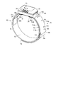
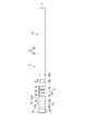
- FIG. 1 is a schematic perspective view showing a bio-mounted device according to the first embodiment.
- FIG. 2 is a schematic perspective view showing a bio-mounted device viewed from a direction different from that of FIG.
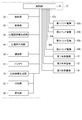
- FIG. 3 is a schematic block diagram showing a bio-mounted device according to the first embodiment.
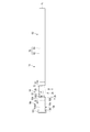
- FIG. 4 is a schematic top view showing a biofitting device according to the first embodiment.
- FIG. 5 is a schematic view of the bio-mounted device in FIG. 4 as viewed from the direction indicated by the arrow V.
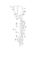
- FIG. 6 is a schematic view of the bio-mounted device in FIG. 5 as viewed from the direction indicated by the arrow VI.
- FIG. 7 is an enlarged view of the position indicated by reference numeral VII in FIG. FIG.
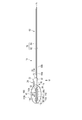
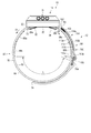
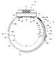
- FIG. 8 is a schematic view showing a biofitting device according to the first embodiment.
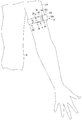
- FIG. 9 is a schematic view showing that when the user is in the anatomical position, the main body of the biofitting device according to the first embodiment is attached so as to face the front of the user.
- FIG. 10 is a schematic top view showing the bio-mounted device according to the second embodiment.
- FIG. 11 is a schematic view of the bio-mounted device in FIG. 10 as viewed from the direction indicated by the arrow XI.
- FIG. 12 is a schematic view of the bio-mounted device in FIG. 11 as viewed from the direction indicated by the arrow XII.
- FIG. 13 is a schematic view showing a biofitting device according to the second embodiment.
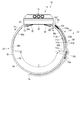
- FIG. 14 is a schematic view showing a biofitting device according to a third embodiment.
- FIG. 15 is a schematic view showing a band with electrodes for a bio-mounted device according to a fourth embodiment.
- the electrode-attached band 12 including the electrodes 68a and 68b is attached to an appropriate position such as an appropriate limb (upper limb or lower limb), chest, abdomen, and waist of the user's body B.
- the band 12 may be attached to the user's head.
- the band 12 is used together with the main body 14.
- the band 12 is a second band in which a first band portion 62 whose length is largely adjusted (initially adjusted) according to a user's mounting position, and a first elastic portion 112 and a second elastic portion 114 having different elasticity are arranged so as to overlap each other. It has a band portion 64.
- the folded portion 106 and the ring member 110 between the first expansion / contraction portion 112 and the second expansion / contraction portion 114 move in the circumferential direction (longitudinal direction) of the band 12 according to the movement of the user at the position where the band 12 is attached to the user. Moving. Therefore, the band 12 allows the movement of the user in the second band portion 64 and prevents it from being hindered.
- the band 12 and the biofitting device 10 having the band 12 allow the user to move at the position where the band 12 is attached, thereby suppressing causing discomfort to the user.
- the bio-mounted device 10 is configured to detect signals from the living body such as heartbeat, electrocardiographic signal, and myoelectricity. Further, the living body wearing device 10 may be configured to perform treatment by applying an electric signal such as a low frequency to the living body.
- the electrode-attached band 12 used together with the bio-mounted device 10 and the bio-mounted device 10 will be described with reference to FIGS. 1 to 9.
- a case where the biological device 10 measures a heartbeat and an electrocardiographic signal will be described as an example.
- the bio-mounted device 10 has an electrode-attached band (belt) 12 for the bio-mounted device 10 and a main body portion 14 provided on the band 12.
- the band 12 of the biofitting device 10 is fixed to the main body 14.
- the bio-attached device 10 including the band 12 and the main body 14 is wrapped around and attached to the user (living body), for example, the limbs (upper limbs or lower limbs) by the band 12.
- the band 12 is formed to a length that can be attached to the user's limbs.
- the biofitting device 10 is formed in a size and weight that can be easily operated by the user while being attached to the user's limbs by the band 12.
- the band 12 is formed to a length that is attached to the user's chest, lumbar region, or head.
- the biofitting device 10 is attached to the upper left arm of the user.
- the main body 14 includes a frame (exterior body) 22, an operation unit 24 provided on the frame 22, a display unit 26 provided on the frame 22, and a pair of support portions 28a and 28b provided on the frame 22.
- the frame 22 is made of a material having electrical insulation. With the biological attachment device 10 attached to the upper left arm of the user, the support portions 28a and 28b are on the biological side (back side) with respect to the frame 22, and the operation portion 24 is in a position where it can be operated by the fingers of the user's hand or the like.
- the display unit 26 is located at a position visible to the user, that is, on the side opposite to the living body (front surface side).
- the support portions 28a and 28b are formed in a substantially wedge shape, for example.
- the support portions 28a and 28b project from the back surface of the frame 22 and form a part of the annular body when attached to the upper left arm of the living body in cooperation with the frame 22 and the band 12.
- the support portions 28a and 28b are separated from each other in the longitudinal direction of the band 12.
- the longitudinal direction is a direction along the extending direction (circumferential direction) of the band 12 with respect to the main body portion 14.
- the direction in which the first band portion (longitudinal band) 62 described later extends from the main body portion 14 is the first direction D1
- the direction in which the second band portion (short band) 64 described later extends from the main body portion 14 is defined as the first direction D1.
- the second direction is D2.
- the back surface of the frame 22 between the support portions 28a and 28b is flat.
- the support portions 28a and 28b are inclined with respect to the back surface of the frame 22 so as to easily contact the upper left arm of the living body.
- the support portion 28a, the back surface of the frame 22, and the support portion 28b are formed in a substantially arc shape as a whole.
- the support portions 28a and 28b are made of a flexible material such as a rubber material or a resin material that can be elastically deformed.
- the first main body electrode 30 is fixed to the back surface of the frame 22 of the main body 14.
- the second main body electrode 32 is fixed to one of the support portions 28a.
- a third main body electrode 34 is fixed to the other support portion 28b.
- the first to third main body electrodes 30, 32, 34 are used as a sensor or a transducer for detecting an electric potential.
- the first main body electrode 30, the second main body electrode 32, and the third main body electrode 34 are formed in a plate shape by, for example, a conductive metal plate or a conductive elastomer, and are separated from each other.
- the main body portion 14 has three main body electrodes 30, 32, 34 will be described.
- the three main body electrodes 30, 32, and 34 may be electrically connected to each other and formed so as to be equated as one electrode, or may be formed as one plate-shaped electrode.
- the main body unit 14 includes a control unit 42, an electrocardiogram information generation unit 44, an electrocardiogram generation unit 46, a communication unit 48, and a battery 50.
- the main body portion 14 further includes a light emitting unit 52, a light receiving unit 54, and a heartbeat information generating unit 56.
- the control unit 42, the electrocardiogram information generation unit 44, the electrocardiogram generation unit 46, the communication unit 48, the battery 50, the light projecting unit 52, the light receiving unit 54, and the heartbeat information generation unit 56 are mounted on the control board 40 built in the frame 22. It is provided.
- the control board 40 is further provided with an operation unit 24 and a display unit 26.
- the control unit 42 includes an operation unit 24, a display unit 26, a first main body electrode 30, a second main body electrode 32, a third main body electrode 34, an electrocardiogram information generation unit 44, an electrocardiogram generation unit 46, a communication unit 48, and a light projecting unit.
- the 52, the light receiving unit 54, and the heartbeat information generation unit 56 are electrically connected, for example.
- the control unit 42 is electrically connected to the first to fourth band electrodes (biological signal detection units) 66a, 66b, 68a, 68b, which will be described later.
- the control unit 42 includes an operation unit 24, a display unit 26, a first main body electrode 30, a second main body electrode 32, a third main body electrode 34, an electrocardiogram information generation unit 44, an electrocardiogram generation unit 46, a communication unit 48, and a light projecting unit 52.
- the light receiving unit 54, the heartbeat information generation unit 56, and the first to fourth band electrodes 66a, 66b, 68a, 68b can be controlled, respectively.
- the control unit 42 deploys a control program stored in a memory such as a ROM by, for example, one or a plurality of processors in the RAM according to the power from the battery 50, and the operation unit 24, the display unit 26, and the first main body electrode.
- a control program stored in a memory such as a ROM by, for example, one or a plurality of processors in the RAM according to the power from the battery 50, and the operation unit 24, the display unit 26, and the first main body electrode.
- a control program stored in a memory such as a ROM by, for example, one or a plurality of processors in the RAM according to the power from the battery 50, and the operation unit 24, the display unit 26, and the first main body electrode.
- 2nd main body electrode 32, 3rd main body electrode 34, electrocardiogram information generation unit 44, electrocardiogram generation unit 46, communication unit 48, light projection unit 52, light receiving unit 54, heartbeat information generation unit 56, and 1st to 1st Appropriate processing is performed on the 4-band electrode
- one or more processors read the program via the network, and the operation unit 24, the display unit 26, the first main body electrode 30, the second main body electrode 32, the third main body electrode 34, and the electrocardiogram information. Appropriate processing is executed for the generation unit 44, the electrocardiogram generation unit 46, the communication unit 48, the light projection unit 52, the light receiving unit 54, the heart rate information generation unit 56, and the first to fourth band electrodes 66a, 66b, 68a, 68b. do.
- the control unit 42 includes an operation unit 24, a display unit 26, a first main body electrode 30, a second main body electrode 32, a third main body electrode 34, an electrocardiogram information generation unit 44, an electrocardiogram generation unit 46, a communication unit 48, and a light projecting unit 52.
- the light receiving unit 54, the heartbeat information generation unit 56, and the first to fourth band electrodes 66a, 66b, 68a, 68b can be controlled by a circuit (for example, ASIC) that realizes one or more functions. ..
- the operation unit 24 has an operation button into which instructions such as power ON / OFF of the main body unit 14, measurement start, and measurement stop operations are input.
- the display unit 26 causes the user to recognize the operating state of the main body unit 14 (operating state of the control unit 42) by, for example, emitting light from an LED (Light Emitting Diode).
- the user can grasp the operating state of the main body unit 14 by recognizing the light emitting color, the light emitting pattern, and the like of the display unit 26 controlled by the control unit 42.
- the operating state is, for example, an indication that the power is turned on by the operation of the operation unit 24, that measurement is being performed using the main body unit 14, an appropriate signal is measured, and an external device is communicated using the communication unit 48. Including that the information is properly transmitted to.
- the display unit 26 may be formed as a screen for displaying electrocardiogram information such as a waveform generated by the electrocardiogram generation unit 46 and heartbeat information generated by the heartbeat information generation unit 56.
- electrocardiogram information such as a waveform generated by the electrocardiogram generation unit 46 and heartbeat information generated by the heartbeat information generation unit 56.
- An example of a screen is a liquid crystal display or an organic electroluminescence display.
- the operation unit 24 and the display unit 26 are formed as an integrated touch panel.
- the operation unit 24 converts the command into an electric signal by being operated by the user.
- the display unit 26 can display electrocardiogram information, heartbeat information, and other operating states of the control unit 42.
- the first to fourth band electrodes 66a, 66b, 68a, 68b are used, for example, as a sensor or a transducer for obtaining potential information.
- the electrocardiogram information generation unit 44 selectively uses a plurality of the first to third main body electrodes 30, 32, 34 and the first to fourth band electrodes 66a, 66b, 68a, 68b to obtain potential difference information. , Generate electrocardiogram information by signal processing.
- the electrocardiogram generation unit 46 generates information on the electrocardiogram based on the electrocardiogram information generated by the electrocardiogram information generation unit 44.
- the electrocardiogram information generated by the electrocardiogram information generation unit 44 and the information about the electrocardiogram generated by the electrocardiogram generation unit 46 are transmitted to the external device of the biofitting device 10 by the communication unit 48 controlled by the control unit 42 and stored in the external device. ..
- the external device is a data server, a PC, a smartphone or a tablet terminal. It is also preferable that the electrocardiogram information generated by the electrocardiogram information generation unit 44 and the information related to the electrocardiogram generated by the electrocardiogram generation unit 46 are stored in a storage unit (not shown) in the main body unit 14.
- the light projecting unit 52 can emit light having an appropriate wavelength toward the living body through the window unit 22a in the first main body electrode 30 on the back surface shown in FIG. 1 of the frame 22.
- the light receiving unit 54 can receive the reflected light of the light emitted from the light projecting unit 52 toward the living body through the window unit 22a.
- the heartbeat information generation unit 56 appropriately processes a signal to generate heartbeat information based on the information obtained by projecting light on the living body by the light emitting unit 52 and obtaining the reflected light from the living body by the light receiving unit 54 and performing photoelectric conversion. ..
- the heartbeat information generated by the heartbeat information generation unit 56 is transmitted to the external device of the biofitting device 10 by the communication unit 48 controlled by the control unit 42 and stored in the external device. It is also preferable that the heartbeat information generated by the heartbeat information generation unit 56 is stored in a storage unit (not shown) in the main body unit 14.
- the band 12 extends from the main body portion 14 in two directions D1 and D2 in opposite directions.
- the band 12 has a first band portion (first belt portion) 62 and a second band portion (second belt portion) 64.
- the first band portion 62 and the second band portion 64 are band-shaped (strap-shaped or strip-shaped) and extend along the longitudinal direction.
- Two band electrodes (first and second band electrodes) 66a and 66b are fixed to the first band portion 62.
- the second band electrode 66b fixed to the first band portion 62 may be removable from the first band portion 62. It is preferable that a plurality of electrodes 66a and 66b are arranged in the first band portion 62, but one may be used.
- Two band electrodes (third and fourth band electrodes) 68a and 68b are fixed to the second band portion 64.
- the fourth band electrode 68b fixed to the second band portion 64 may be removable from the second band portion 64. It is preferable that a plurality of electrodes 68a and 68b are arranged in the second band portion 64, but one may be used.
- the first band portion 62 not only the second band electrode 66b but also the first band electrode 66a may be removable.
- the fourth band electrode 68b but also the third band electrode 68a may be removable.
- the main body 14 is fixed to a desired position on the upper left arm, for example, by using the band 12.
- the lengths of the first band portion 62 and the second band portion 64 of the band 12 may be constant regardless of the user who assumes the attachment, or may be changed according to the user who assumes the attachment. For example, a lineup of bands 12 having lengths assuming adults, children, men, women, and the like may be used.
- the lengths of the first band portion 62 and the second band portion 64 of the band 12 may be the same length as when they are attached to the lower limbs instead of the upper limbs such as the upper left arm, and they are assumed to be attached. It may be changed according to the position.
- the first band portion 62 has one end 72, the other end 74, and an expansion / contraction portion (first band portion side expansion / contraction portion) 76.
- One end 72 of the first band portion 62 is supported by the main body portion 14. It is preferable that the first band portion 62 can be rotated at one end 72, for example, along the living body.
- the other end 74 of the first band portion 62 is an open end.
- the stretchable portion 76 of the first band portion 62 has the first stretchability that stretches and contracts along the longitudinal direction.
- the first stretchable stretchable portion 76 along the longitudinal direction of the first band portion 62 is substantially formed as a hard stretchable portion or a non-stretchable portion that hardly stretches along the longitudinal direction.
- the first stretchability of the first band portion 62 has substantially the same meaning as poor stretchability or non-stretchability.
- the stretchability in the width direction orthogonal to the longitudinal direction of the stretchable portion 76 of the first band portion 62 is substantially the same as, for example, the first stretchability.
- the first band portion 62 has a base material 82 having higher elasticity in the longitudinal direction than the first elasticity, and an elasticity adjusting member 84 fixed to the base material 82.
- the base material 82 expands and contracts more along the longitudinal direction per unit length than the first elasticity of the expansion and contraction portion 76.
- the base material 82 is made of cloth, for example.
- a stretch material such as polyurethane, cotton, or rubber can be used.
- the adjusting member 84 a material having lower elasticity along the longitudinal direction than the base material 82 is used.
- the adjusting member 84 is made of cloth, for example.
- a material having substantially non-stretchable or non-stretchable material is used.
- the base material 82 and the adjusting member 84 are formed long along the longitudinal direction.
- the base material 82 defines one end 72 and the other end 74 along the longitudinal direction.
- the length of the adjusting member 84 is slightly shorter than the length of the base material 82.
- the adjusting member 84 is fixed between one end 72 and the other end 74 of the base material 82.
- the base material 82 and the adjusting member 84 are sewn or affixed and fixed.
- the outer edge of the adjusting member 84 is inside the outer edge of the base material 82.
- the base material 82 is on the living body side when the living body wearing device 10 is attached to the living body.
- the adjusting member 84 is on the opposite side of the living body when attached to the living body.
- the base material 82 and the adjusting member 84 have flexibility.
- the base material 82 and the adjusting member 84 are made of a material having electrical insulation.
- the adjusting member 84 which is slightly shorter than the total length of the first band portion 62 and has lower elasticity than the base material 82, is fixed to the base material 82, so that the base material 82 expands and contracts as a whole. Elasticity decreases with respect to sex.
- the first stretchability in the longitudinal direction of the first band portion 62 is substantially the same as the stretchability in the longitudinal direction of the adjusting member 84, and has substantially low stretchability or non-stretchability.
- a hook-and-loop fastener for example, a hook-and-loop fastener is used. It is preferable to use a hook-and-loop fastener in which hooks and loops are mixed on the same surface.
- the length of the first band portion 62 is adjusted by being folded back at an appropriate portion where the base material 82 and the adjusting member 84 overlap each other and connected by contact between the surface fasteners of the adjusting member 84. Therefore, the hook-and-loop fastener of the adjusting member 84 of the first band portion 62 is folded back by the ring member 110 toward a position outside the first band portion 62, and the length of the first band portion 62 is adjusted. It is a connection portion that can be attached to and detached from the outside of the first band portion 62.
- the first band electrode 66a is fixed at a position close to the second main body electrode 32 in the base material 82 of the first band portion 62.
- the second band electrode 66b is fixed at a position of the base material 82 of the first band portion 62 that is separated from the second main body electrode 32 by the first band electrode 66a.
- the first band electrode 66a and the second band electrode 66b are adjacent to each other in the longitudinal direction.
- the first band electrode 66a and the second band electrode 66b are formed in a plate shape by a conductive metal plate or a conductive elastomer, and hardly extend in the longitudinal direction.
- the first band electrode 66a is electrically connected to the control unit 42 of the control board 40 of the main body unit 14 through the wiring 67a arranged in the first band unit 62.
- the second band electrode 66b is electrically connected to the control unit 42 of the control board 40 of the main body unit 14 through the wiring 67b arranged in the first band unit 62.
- the second band portion 64 includes a band-shaped band main body 100 and a ring-shaped ring member 110 provided at a position at a band end along the longitudinal direction of the second band portion 64. Has.
- the band body 100 has one end 102, the other end 104, a folded-back portion 106, and a fixed portion (joint portion) 108.
- the band body 100 is continuous between one end 102 and the other end 104.
- One end 102 of the band main body 100 is supported by the main body portion 14.
- the second band portion 64 can be rotated at one end 102, for example, along the living body.
- the band end of the second band portion 64 is located at the most distal position with respect to one end 102 of the band body 100 along the second direction D2 in the longitudinal direction.
- the band body 100 is folded back at the folded-back portion 106 at the ring member 110 at the position of the band end of the second band portion 64.
- the folded-back portion 106 is located at the most distal position with respect to one end 102 of the second band portion 64 along the second direction D2 in the longitudinal direction.
- the other end 104 of the second band portion 64 is located between the one end 102 and the folded portion 106 along the longitudinal direction.
- a fixing portion 108 is provided at the other end 104 of the second band portion 64.
- the fixing portion 108 is located proximal to the main body portion 14 with respect to the folded portion 106 along the longitudinal direction.
- the area between one end 102 of the band body 100 and the folded portion 106 is formed as a first expansion / contraction portion (first expansion / contraction region) 112.
- the area between the folded portion 106 and the other end 104 of the band body 100 is formed as a second expansion / contraction portion (second expansion / contraction region) 114.
- the first telescopic portion 112 and the second telescopic portion 114 are strip-shaped (strap-shaped or strip-shaped).
- a folded-back portion 106 is provided between the first telescopic portion 112 and the second telescopic portion 114.
- the inner layer (inside) of the second band portion 64 has a first expansion / contraction portion 112, and the outer layer (outside) of the first expansion / contraction portion 112 has a second expansion / contraction portion 114.
- the first telescopic portion 112 has a first surface 112a and a second surface 112b on the opposite side of the first surface 112a.
- the second telescopic portion 114 has a first surface 114a and a second surface 114b opposite to the first surface 114a.
- the first telescopic portion 112 is continuously formed at a position close to one end 102 of the second band portion 64. In the path between the distal end (boundary) 113a of the first telescopic portion 112, which is the most distal end along the longitudinal direction from one end 102, and the fixing portion 108, the folded portion 106 and the second telescopic portion (second telescopic portion) There are 2 telescopic regions) 114.
- the first telescopic portion 112 and the folded portion 106 are continuous with each other by the boundary 113a.
- the folded-back portion 106 and the second telescopic portion 114 are continuous with each other by the boundary 113b.
- the boundaries 113b of this embodiment are not clearly distinguishable.
- two telescopic portions 112 and 114 are formed in a continuous state by a folded portion 106, and the two telescopic portions 112 and 114 are overlapped with each other.
- the second telescopic portion 114 is overlapped with the first telescopic portion 112 on the second surface 112b side of the first telescopic portion 112. Therefore, the second surface 112b of the first expansion / contraction portion 112 and the second surface 114b of the second expansion / contraction portion 114 face each other or come into contact with each other.
- the fixing portion 108 fixes between the second surface 112b of the first expansion / contraction portion 112 and the second surface 114b of the second expansion / contraction portion 114.
- the first telescopic portion 112 is located in the second direction D2 along the longitudinal direction with respect to the main body portion 14. It is preferable that the first stretchable portion 112 has the first stretchability along the longitudinal direction. As described above, the first stretchability is hardly stretchable or non-stretchable, and does not substantially stretch. Third and fourth band electrodes 68a and 68b are provided on the first surface 112a of the first telescopic portion 112.
- the third and fourth band electrodes 68a and 68b are formed in a plate shape by a conductive metal plate or a conductive elastomer, and hardly expand or contract in the longitudinal direction and the direction orthogonal to the longitudinal direction.
- the third band electrode 68a is electrically connected to the control unit 42 of the control board 40 of the main body unit 14 through the wiring 69a arranged in the second band unit 64.
- the fourth band electrode 68b is electrically connected to the control unit 42 of the control board 40 of the main body portion 14 through the wiring 69b arranged in the first expansion / contraction portion 112 of the second band portion 64.
- the wirings 69a and 69b are provided, for example, between the first surface 112a and the second surface 112b of the first telescopic portion 112. It is preferable that the wirings 69a and 69b are not exposed to the outside of the first telescopic portion 112.
- the folding portion 106 folds the band body 100 at the ring member 110. Therefore, the band main body 100 is folded back by the folded-back portion 106, so that the first expansion / contraction portion 112 and the second expansion / contraction portion 114 are overlapped.
- the folded-back portion 106 is on the second direction D2 side along the longitudinal direction with respect to the first telescopic portion 112.
- the folded-back portion 106 has a second elasticity that expands and contracts larger in the longitudinal direction per unit length than the first elasticity of the first expansion and contraction portion 112.
- the folded-back portion 106 is located at a certain distance from the electrode 68b. There is a boundary 113a between the folded-back portion 106 and the electrode 68b.
- the elasticity in the width direction orthogonal to the longitudinal direction of the first expansion / contraction portion 112 of the second band portion 64 and the elasticity in the width direction orthogonal to the longitudinal direction of the second expansion / contraction portion 114 are abbreviated as, for example, the first elasticity. It is the same.
- the second band portion 64 has a base material (base) 122 that becomes the upper left arm side (living body side) when attached to the upper left arm of the living body, and an elastic adjusting member 124 that is on the outer side away from the upper left arm.
- the base material 122 and the adjusting member 124 are formed long along the longitudinal direction.
- the base material 122 and the adjusting member 124 have flexibility.
- the base material 122 and the adjusting member 124 are made of an electrically insulating material.
- the base material 122 and the adjusting member 124 are sewn or affixed and fixed.
- the outer edge of the adjusting member 124 is inside the outer edge of the base material 122.
- the base material 122 is made of cloth, for example.
- a stretch material such as polyurethane, cotton, or rubber can be used.
- the base material 122 has a third elasticity that expands and contracts more in the longitudinal direction than the first elasticity.
- a material having a lower elasticity along the longitudinal direction than the base material 122 is used.
- the adjusting member 124 is made of cloth, for example.
- the adjusting member 124 has a fourth elasticity that is more difficult to expand and contract along the longitudinal direction than the third elasticity.
- the fourth stretchability is poorly stretchable or non-stretchable, as is the case with the first stretchability, for example.
- the adjusting member 124 is located between one end 102 and a position where the folded portion 106 is formed along the longitudinal direction of the base material 122.
- the adjusting member 124 is not arranged at a position where it becomes a folded-back portion 106.
- the elasticity in the longitudinal direction of the region where the adjusting member 124 having the fourth elasticity is fixed to the base material 122 having the third elasticity is substantially the same as the fourth elasticity in the longitudinal direction of the adjusting member 124.
- the fourth elasticity is substantially the same as the first elasticity. Therefore, the region in which the adjusting member 124 having low elasticity is fixed to the base material 122 along the longitudinal direction is formed as the first elastic portion 112 having the first elasticity.
- the elasticity of the region in which the adjusting member 124 is not fixed to the base material 122 in the longitudinal direction is substantially the same as the third elasticity in the longitudinal direction of the base material 122.
- the third elasticity is substantially the same as the second elasticity. Therefore, the region in which the adjusting member 124 is not fixed to the base material 122 along the longitudinal direction is formed as the second stretchable portion 114 having the second stretchability.
- the folded-back portion 106 of the second band portion 64 is formed in the same manner as the second stretchable portion 114 (base material 122) having higher elasticity along the longitudinal direction than the first stretchability.
- the folded-back portion 106 does not have an adjusting member 124. Therefore, the folded-back portion 106 can be expanded and contracted in the longitudinal direction as compared with the first expansion and contraction portion 112, similarly to the second expansion and contraction portion 114.
- the fixing portion 108 joins the second surface 114b of the second expansion / contraction portion 114 including the other end 104 of the second band portion 64 and the second surface 112b outside the first expansion / contraction portion 112 of the second band portion 64. .. Therefore, the fixing portion 108 is located proximal to the main body portion 14 of the folded portion 106 on the second direction D2 side along the longitudinal direction with respect to the main body portion 14, and is the first expansion / contraction portion 112 and the second expansion / contraction portion 112. Join with 114.
- annular ring member 110 is supported on the folded portion 106.
- the ring member 110 is used when connecting between the first band portion 62 and the second band portion 64.
- the ring member 110 is formed, for example, in a rectangular ring shape.
- the ring member 110 is preferably formed of, for example, a material having electrical insulation.
- the ring member 110 can move along the longitudinal direction due to the second elasticity of the second expansion / contraction portion 114.
- the operation of the bio-mounted device 10 will be described by taking the case where the bio-mounted device 10 is attached to the upper left arm UA of the living body as an example.
- the user uses the other end 74 of the first band portion 62 from the inside to the outside of the ring member 110 supported by the folded portion 106 of the second band portion 64.
- the band 12 and the main body 14 form an annular shape.
- the user brings the first to third main body electrodes 30, 32, 34 and the first to fourth band electrodes 66a, 66b, 68a, 68b of the main body 14 directly into contact with the skin of the user's upper left arm UA.
- the user determines the positions of the electrodes 30, 32, 34 of the main body portion 14, the electrodes 66a, 66b of the first band portion 62, and the electrodes 68a, 68b of the second band portion 64 with respect to the upper left arm UA.
- the attachment position of the biofitting device 10 with respect to the user's upper left arm UA is such that when the user's body B is positioned in the anatomical position, the main body 14 faces the user's anterior. Is preferable.
- the minimum and maximum values of the applicable circumference of the bio-mounted device 10 to the upper left arm UA are predetermined.
- the user adjusts the length of the telescopic portion 76 of the first band portion 62 according to the outer peripheral length of the upper left arm UA, and adjusts the position of the folded portion 76a with respect to the ring member 110. That is, the user adjusts the positions of the folded-back portion 76a and the end portion 74 of the first band portion 62 to initially adjust the peripheral length of the band 12 when the band 12 is attached to the upper left arm UA.
- the first band portion 62 and the ring member 110 are folded back at desired positions, and the elasticity adjusting members (connecting portions) 84 of the surface fasteners are fastened to each other.
- the position of the first band portion 62 with respect to the user's upper left arm UA is fixed.
- the biofitting device 10 is maintained in a state of being attached to the upper left arm UA of the user.
- the user fixes the first band portion 62 via the ring member 110, and the biofitting device 10 becomes an annular body, so that the second and third main body electrodes 32 and 34 are pressed against the skin (skin) of the upper left arm UA. Then, the support portions 28a and 28b are elastically deformed. Therefore, the electrodes 32 and 34 are in close contact with the skin of the upper left arm UA.
- the first main body electrode 30 is located between the second and third main body electrodes 32 and 34, and the second and third main body electrodes 32 and 34 are pressed against the skin of the upper left arm UA and adhere to the skin of the upper left arm UA. Adhere to.
- first and second band electrodes 66a and 66b provided in the flexible first band portion 62 are in close contact with the skin of the upper left arm UA and are provided in the flexible second band portion 64.
- the 3rd and 4th band electrodes 68a and 68b are brought into close contact with the skin of the upper left arm UA.
- Reference numeral L in FIG. 8 is the peripheral length between the electrode 66b of the first band portion 62 and the ring member 110.
- the length L varies depending on the thickness of the user's upper left arm UA or the attachment site. For example, when the outer diameter of the upper left arm UA of the user is relatively small and the length L is short, the electrodes 66b and 68b are close to each other in a separated state, and the electrodes 30, 32, 34, 66a, 66b, 68a and 68b allow the user to use the electrodes 30, 32, 34, 66a, 66b, 68a and 68b.
- Electrodes 30, 32, 34, 66a, 66b, 68a, 68b come into contact with the surface of the skin so as to substantially cover the upper left arm UA. At this time, the path from the electrode 66b to the electrode 68b through the ring member 110 is shorter than the path from the electrode 66b to the electrode 68b through the main body 14.
- the contact area including the electrodes 30, 32, 34, 66a, 66b, 68a, 68b is the first band portion 62 and the second band portion.
- the 64 itself can be larger than the contact area in contact with the user's upper left arm UA.
- the electrodes 66b and 68b are separated from each other. At this time, the path from the electrode 66b to the electrode 68b through the main body 14 may be shorter than the path from the electrode 66b to the electrode 68b through the ring member 110.
- the user appropriately operates the operation unit 24 with the bio-mounted device 10 properly attached to the user's upper left arm UA.
- the control unit 42 starts communication with the external device by the communication unit 48.
- the main body 14 is set to the potential of the skin surface of the upper arm UA by the control unit 42 by the first to third main body electrodes 30, 32, 34, and by the first to fourth band electrodes 66a, 66b, 68a, 68b.
- the corresponding signal (electrocardiographic signal) is detected.
- the first to third main body electrodes 30, 32, 34 and the first to fourth band electrodes 66a, 66b, 68a, 68b output a signal corresponding to the potential to the electrocardiogram information generation unit 44.
- the electrocardiogram information generation unit 44 uses one selected from the first to third main body electrodes 30, 32, 34 and the first to fourth band electrodes 66a, 66b, 68a, 68b as a reference electrode, and uses this reference electrode as a reference electrode.
- the potential difference between the detected potential of the above and the detected potentials of the remaining plurality of electrodes is calculated, and information on the electrocardiographic signal is generated based on the negative maximum value and the positive maximum value of the calculated results.
- the electrocardiogram information generation unit 44 obtains information on the electrocardiographic signal based on the detection potential of the selected electrode.
- the electrocardiogram information generation unit 44 can obtain information not only from one electrode pair (paired electrodes) but also from a plurality of electrode pairs.
- the electrocardiogram information generation unit 44 generates an electrocardiographic signal by using a stronger signal among the signals obtained from the plurality of electrode pairs.
- the electrocardiogram generation unit 46 generates an electrocardiogram waveform based on the information obtained by the electrocardiogram information generation unit 44.
- the heartbeat information generation unit 56 obtains heartbeat information based on the detection state of the light projected from the light projecting unit 52 to the upper left arm UA and the reflected light from the upper left arm UA.
- the main body 14 of the biofitting device 10 measures the user's electrocardiographic signal and heartbeat, and obtains information on each.
- the user can easily recognize the state of his / her heart by looking at the display screen of the PC, smartphone, tablet terminal, etc. connected by the communication unit 48.
- the electrocardiographic signal measurement and the heart rate measurement be performed over several hours until an appropriate time elapses.
- An example of measuring an electrocardiographic signal and measuring a heart rate for several hours is, for example, during active hours or during sleep.
- the size (perimeter) of the outer circumference of the upper left arm UA may change according to the movement of the left arm.
- the circumference becomes relatively small, and when the arm is bent, the circumference becomes larger than when the arm is extended.
- the band 12 with electrodes has a first elastic portion 112, a second elastic portion 114 having a larger elasticity than the first elastic portion 112, and a first elastic portion 112 and a second elastic portion. It has a folded-back portion 106 between and 114.
- the second band portion 64 has a second stretchable region in a continuous region from the boundary 113a between the first stretchable portion 112 and the folded portion 106 to the fixed portion 108.
- the second stretchable portion 114 expands and contracts in the longitudinal direction (circumferential direction) according to the movement of the upper left arm (living body) UA at the position where the band 12 is attached, and has a second stretchable portion continuous with the second stretchable portion 114.
- the folded portion 106 expands and contracts in the longitudinal direction.
- the relative positions of the folded-back portion 106 and the ring member 110 change according to the expansion and contraction of the second stretchable portion 114 and the folded-back portion 106 in the longitudinal direction. Therefore, the peripheral length of the band 12 is adjusted by the second band portion 64.
- the boundary 113a between the first stretchable portion 112 having low elasticity or non-stretchability of the second band portion 64 and the folded-back portion 106 having appropriate elasticity is on the side in close contact with the upper left arm UA of the user.
- the region is continuously formed as a region having second elasticity.
- the fixing portion 108 is located proximal to the main body portion 14 with respect to the folded portion 106 along the longitudinal direction. Therefore, the length of the second telescopic portion 114 along the longitudinal direction can be made relatively long. Therefore, the second band portion 64 can have a relatively large expansion / contraction region along the longitudinal direction.
- the folded-back portion 106 and the second telescopic portion 114 expand and contract along the longitudinal direction of the band 12 according to the movement of the left arm.
- the elasticity of the folded portion 106 of the second band portion 64 along the longitudinal direction (circumferential direction) makes it easier for the band 12 to follow the movement of the upper left arm UA. Therefore, it is possible to suppress causing discomfort to the user when the bio-mounted device 10 is attached to the upper left arm UA of the user.
- the electrodes 66a and 66b are provided at a portion having the first elasticity. That is, in the first band portion 62, the electrodes 66a and 66b are provided in the first band portion 62 having less elasticity or non-stretchability than the second expansion / contraction portion 114 of the second band portion 64. ..
- the electrodes 68a and 68b are provided on the first stretchable portion 112 which is adjacent to the main body portion 14 and has the first stretchability. That is, in the second band portion 64, the electrodes 68a and 68b are provided on the first stretchable portion 112 having less stretchability or non-stretchability than the second stretchable portion 114 of the second band portion 64.
- the biofitting device 10 maintains the positional relationship between the upper left arm UA and the electrodes 66a, 66b, 68a, 68b in a fixed state.
- the body 14 faces the user's anterior when the user is in the anatomical position after the user has appropriately moved his left arm.
- the electrodes 30, 32, 34, 66a, 66b, 68a, 68b are maintained in contact with the user's upper left arm UA. Therefore, the biological device 10 can detect a stable electrocardiographic signal using the electrodes 66a, 66b, 68a, 68b, and detect a heartbeat signal using the light emitting unit 52 and the light receiving unit 54.
- the portion of the first band portion 62 in which the wirings 67a and 67b connecting the electrodes 66a and 66b and the control portion 42 are housed is made of a material having low elasticity or non-stretchability.
- the portion in which the wirings 69a and 69b connecting the electrodes 68a and 68b and the control portion 42 are housed is made of a material having low elasticity or non-stretchability. Therefore, even if the user appropriately moves the left arm, it is difficult to apply a force to extend the wirings 67a, 67b, 69a, 69b so as to extend the wirings 67a, 67b, 69a, 69b.
- the control unit 42 automatically ends the detection of the information related to the electrocardiographic signal and the heartbeat information after obtaining the electrocardiogram information and the heartbeat information for a preset time, for example.
- the control unit 42 automatically turns off the power of the main body unit 14 after finishing the detection of the information related to the electrocardiographic signal and the heartbeat information. After that, the user releases the fixation of the first band portion 62 of the bio-mounted device 10, and removes the bio-mounted device 10 from the upper left arm UA.
- the bio-mounted device 10 is maintained without being removed while the circumference changes according to the movement of the left arm from the start to the end of the detection of the information related to the electrocardiographic signal and the heartbeat information.
- the state in which the electrodes 30, 32, 34, 66a, 66b, 68a, 68b are in contact with the skin of the upper left arm UA is maintained.
- the bio-mounted device 10 can stably detect the information related to the electrocardiographic signal and the heartbeat information from the start to the end of the user's electrocardiogram and heartbeat test. ..
- the bio-mounted device 10 is used in this way.
- the biological device 10 is used not only for a relatively long measurement of several hours such as during sleep or activity, but also for a relatively short time such as within one minute or several minutes. It can also be used for measurement of. Therefore, the band 12 can also be used when the main body portion 14 is maintained in a state of being attached to the living body for a relatively short time within a few minutes, for example.
- the biofitting device 10 is attached to the upper left arm UA of the user has been described.
- the bio-mounted device 10 may be worn, for example, on the user's wrist or lower limb.
- the lower limbs include the thighs, lower legs, ankles, and the like.
- the bio-mounted device 10 can use the band 12 for the bio-mounted device 10 that is attached to a limb to obtain biometric information, such as myoelectric information, in addition to information related to electrocardiographic signals.
- biometric information such as myoelectric information
- a pulse wave sensor may be used instead of the electrode 30, or the light emitting unit 52 and the light receiving unit 54.
- the biofitting device 10 calculates the pulse wave velocity (PTT) from the time difference between the R wave peak time of the information related to the electrocardiographic signal and the rising point of the pulse wave information using the pulse wave sensor, and estimates the blood pressure. do.
- PTT pulse wave velocity
- the biomedical device 10 is preferably attached not only to detect a biological signal but also to a living body for treating the living body. That is, the band 12 can be used to maintain the state in which the main body portion 14 having a function of treating the living body is attached to the living body.
- the user can attach the biofitting device 10 to the chest, abdomen, and the abdomen. Alternatively, it may be attached to the waist.
- the stretchable portion 76 of the first band portion 62 may have higher stretchability than when it has low stretchability or non-stretchability. At this time, the elasticity of the expansion / contraction portion 76 of the first band portion 62 is lower than the elasticity of the second expansion / contraction portion 114 of the second band portion 64 along the longitudinal direction. Similarly, the first stretchability of the first stretchable portion 112 of the second band portion 64 is lower than the second stretchability of the second stretchable portion 114. Therefore, the first stretchability may not be limited to non-stretchability or non-stretchability.
- a band 12 with electrodes and a biofitting device 10 capable of suppressing causing discomfort to the user in a state of being mounted at an appropriate position. can.
- the structure of the second telescopic portion 114 of the second band portion 64 can be applied between the electrode 66b of the first band portion 62 and the ring member 110.
- the second embodiment will be described with reference to FIGS. 10 to 13.
- the second embodiment is a modification of the first embodiment, and the same members as those described in the first embodiment or members having the same functions are designated by the same reference numerals as much as possible, and detailed description thereof will be omitted.
- the fixing portion (joining portion) 108 has a first fixing member (joining portion) 108a and a second fixing member (joining portion) 108b.
- the first fixing member 108a is fixed to the outer second surface 112b of the first telescopic portion 112 between one end 102 of the band main body 100 of the second band portion 64 and the folded portion 106.
- the second fixing member 108b is fixed to the second surface 114b of the second telescopic portion 114 at the other end 104 of the second band portion 64.
- the first fixing member 108a is, for example, a hook surface or a loop surface of a hook-and-loop fastener.
- the second fixing member 108b is a loop surface of the hook-and-loop fastener, assuming that the first fixing member 108a is the hook surface of the hook-and-loop fastener.
- the second fixing member 108b is the hook surface of the hook-and-loop fastener, assuming that the first fixing member 108a is the loop surface of the hook-and-loop fastener. It is also preferable that the hook and loop fasteners of the first fixing member 108a and the second fixing member 108b are mixed on the same surface. Therefore, the user can attach / detach the first fixing member 108a and the second fixing member 108b.
- the fixed positions (fixed state) of the first fixing member 108a and the second fixing member 108b can be adjusted within the range of the lengths of the first fixing member 108a and the second fixing member 108b in the longitudinal direction.
- the position of the folded-back portion 106 of the band body 100 is adjusted. Therefore, the length of the second band portion 64 can also be adjusted, although it is a small amount as compared with the length adjustment of the first band portion 62.
- the first fixing member 108a and the second fixing member 108b of the second band portion 64 are fixed at temporary positions. As described, the first band portion 62 is fixed. After that, if necessary, the user re-fixes the first fixing member 108a and the second fixing member 108b of the second band portion 64 to a more comfortable state when the left arm is moved.
- the positions of the folded-back portion 106 and the ring member 110 at positions most distal to the second direction D2 of the second band portion 64 with respect to one end 102 of the second band portion 64 are the first fixing member 108a and the second fixing member 108b. It fluctuates depending on the relationship with. Therefore, although it is slightly smaller than the length adjustment range of the first band portion 62, when the biowear device 10 is attached to the user, the circumference length of the biowear device 10 is adjusted by the second band portion 64. Can be done. Since the folded-back portion 106 has higher elasticity than the first stretchable portion 112 which is hardly stretchable or non-stretchable, the folded-back portion 106 expands and contracts accordingly when the left arm is bent and stretched. At this time, since the length of the second band portion 64 in the longitudinal direction can be adjusted, as compared with the case described in the first embodiment, while maintaining a suitable mounting state of the bio-mounted device 10 for the user. It is possible to suppress causing discomfort to the user.
- a band 12 with electrodes and a biofitting device 10 capable of suppressing causing discomfort to the user in a state of being attached at an appropriate position.
- the third embodiment will be described with reference to FIG.
- the third embodiment is a modification of the first embodiment and the second embodiment.
- Members having the same or having the same functions as the members described in the first embodiment and the second embodiment are designated by the same reference numerals as much as possible, and detailed description thereof will be omitted.
- the folded-back portion 106 of the present embodiment has the same configuration as the first telescopic portion 112. Therefore, the folded-back portion 106 according to the present embodiment has the first elasticity.
- the bio-mounted device 10 attached to the user's upper left arm UA
- the circumference of the left arm becomes relatively small
- the circumference of the left arm becomes larger than when the arm is extended.
- the second telescopic portion 114 of the path between the folded portion 106 and the fixed portion 108 extends in the longitudinal direction.
- the path length of the band body 100 between one end 102 and the other end 104 of the second band portion 64 is extended. Therefore, the relative positional relationship of the ring member 110 with respect to the folded-back portion 106 is deviated, and the distance between one end 102 of the second band portion 64 and the folded-back portion 106 is extended.
- the folded-back portion 106 may have the first elasticity.
- the fourth embodiment will be described with reference to FIG.
- the fourth embodiment is a modification of the first to third embodiments.
- Members having the same or having the same functions as the members described in the first to third embodiments are designated by the same reference numerals as much as possible, and detailed description thereof will be omitted.
- the first band portion 62 and the second band portion 64 of the band 12 of the biofitting device 10 are continuous.
- the main body 14 is removable from the band 12.
- the base material 82 of the first band portion 62 and the base material 122 of the second band portion 64 are formed as, for example, one base material (base) 142.
- the base material 142 has a first end 144 corresponding to the other end 74 of the first band 62 and a second end 146 corresponding to the other 104 of the second band 64.
- the fixing portion 108 of the second band portion 64 of the fourth embodiment may have a structure having the first fixing member 108a and the second fixing member 108b described in the second embodiment.
- the main body can be attached to and detached from the position indicated by the broken line indicated by the reference numeral 14 of the band 12.
- the main body 14 one having an appropriate inspection function as described in the first embodiment, one having an appropriate treatment function, or one having a combination of the inspection function and the treatment function can be used.
- general devices that are not medical devices can be used for the main body 14.
- the band 12 with electrodes capable of suppressing causing discomfort to the user in a state of being attached at an appropriate position is provided. Can be provided.
- the band 12 with electrodes preferably has a structure in which wirings 67a, 67b, 69a, 69b and electrodes 66a, 66b, 68a, 68b can be removed.
- the band 12 can be cleaned, disinfected, or the like with the wirings 67a, 67b, 69a, 69b and the electrodes 66a, 66b, 68a, 68b removed from the band 12.
- the bio-mounted device 10 may be configured such that the first band portion 62 and the second band portion 64 are integrated, and the main body portion 14 cannot be easily removed from the band 12.
- the bio-attached device 10 and the bio-attached device 10 capable of suppressing causing discomfort to the user in a state of being mounted at an appropriate position.
- a band 12 with electrodes can be provided.
- the band 12 with electrodes and the bio-mounted device capable of suppressing causing discomfort to the user in a state of being mounted at an appropriate position. 10 can be provided.
- the present invention is not limited to the above embodiment, and can be variously modified at the implementation stage without departing from the gist thereof.
- Each embodiment may be carried out in combination as appropriate, in which case the combined effect can be obtained.
- the above-described embodiment includes various inventions, and various inventions can be extracted by a combination selected from a plurality of disclosed constituent requirements. For example, even if some constituent requirements are deleted from all the constituent requirements shown in the embodiment, if the problem can be solved and the effect is obtained, the configuration in which the constituent requirements are deleted can be extracted as an invention.
Landscapes
- Health & Medical Sciences (AREA)
- Life Sciences & Earth Sciences (AREA)
- Medical Informatics (AREA)
- Animal Behavior & Ethology (AREA)
- Pathology (AREA)
- Engineering & Computer Science (AREA)
- Biomedical Technology (AREA)
- Heart & Thoracic Surgery (AREA)
- Physics & Mathematics (AREA)
- Molecular Biology (AREA)
- Surgery (AREA)
- Biophysics (AREA)
- General Health & Medical Sciences (AREA)
- Public Health (AREA)
- Veterinary Medicine (AREA)
- Cardiology (AREA)
- Measurement And Recording Of Electrical Phenomena And Electrical Characteristics Of The Living Body (AREA)
- Measuring Pulse, Heart Rate, Blood Pressure Or Blood Flow (AREA)
- Electrotherapy Devices (AREA)
Abstract
電極付きバンドは、長手方向に沿って延びる第1バンド部及び第2バンド部を備える。第2バンド部は、第1伸縮部と、電極と、第2伸縮部と、リング部材と、折返部と、接合部とを有する。第1伸縮部は、長手方向に沿って第1伸縮性を有する。電極は第1伸縮部の第1面に設けられる。第2伸縮部は、第1伸縮部の第2面の側で第1伸縮部と重ねられ、第1伸縮部よりも長手方向に沿って大きく伸縮する第2伸縮性を有する。リング部材は、第2バンド部の長手方向に沿うバンド端となる位置に設けられ、第1バンド部と繋がれ得る。折返部は、第1伸縮部と第2伸縮部との間に設けられ、第1伸縮部と第2伸縮部とが重なるようにリング部材において折り返される。接合部は、第1伸縮部の第2面と第2伸縮部とを接合する。
Description
本発明の一態様は、電極付きバンド、及び、生体装着機器に関する。
例えば特許文献1の心拍計測装置は、バンドにより胸部に巻かれた状態で心電信号を検出する。心拍計測装置を環状にするとき、伸縮性を有するストラップと、電極が配置される非伸縮性ベルトとが金具を用いてバンドの周方向に連結される。胸部での心電信号検出では心臓を挟んで電極を配置することで大きな電位差を得ることができるため、非伸縮性ベルトにおける電極間隔は比較的短くてよい。そのため、心拍計測装置は、伸縮部を比較的長く設けることができ、ストラップの長さを容易に調整することができる。
心拍計測装置などの生体装着機器は、バンドを用いて、四肢(上肢又は下肢)に取り付けられる場合がある。その際に、より微小な電位差を検出するためにバンドに配置される電極の数を多くし又は各電極の面積を大きくすると、バンドの周方向に伸縮性を有する部位を組み込むことが難しくなる場合がある。この場合、生体装着機器をバンドによってユーザに取り付けた後、生体装着機器を取り付けた部位の径(周長)の増加にバンドの長さが追従しないことにより、ユーザに不快感を生じさせる可能性がある。
この発明は、適宜の位置に取りつけた状態で、ユーザに不快感を生じさせることを抑制可能な、電極付きバンド、及び、生体装着機器を提供することを目的とする。
本発明は、上述した課題を解決するために、以下の構成を採用し得る。
一態様に係る電極付きバンドは、帯状で、長手方向に沿って延びる第1バンド部と、第1バンド部に対して長手方向に沿う第1方向に設けられ、長手方向に沿って延びる第2バンド部とを備える。第2バンド部は、電気絶縁性を有する第1伸縮部と、導電性の電極と、第2伸縮部と、リング状のリング部材と、折返部と、接合部とを有する。第1伸縮部は、第1面及び第1面とは反対側の第2面を有する帯状で、長手方向に沿って第1伸縮性を有する。電極は第1伸縮部の第1面に設けられている。第2伸縮部は、第1伸縮部の第2面の側で第1伸縮部と重ねられ、帯状で、第1伸縮部の第1伸縮性よりも単位長さあたり長手方向に沿って大きく伸縮する第2伸縮性を有する。リング部材は、第2バンド部の長手方向に沿うバンド端となる位置に設けられ、第1バンド部と繋がれ得る。折返部は、第1伸縮部と第2伸縮部との間に設けられ、第1伸縮部と第2伸縮部とが重なるようにリング部材において折り返される。接合部は、第1伸縮部の第2面と第2伸縮部とを接合する。
長手方向は、バンドの延出方向(周方向)に沿う方向である。電極付きバンドは、例えば1つの第2バンド部において、第1面に電極が設けられた第1伸縮部の第2面に、第1伸縮部よりも伸縮性が大きい第2伸縮部を重ねている。第1伸縮部と第2伸縮部との間の折返部で第1伸縮部と第2伸縮部とが連続している。このようなバンドを生体に取り付けた状態において、第2バンド部における第2伸縮部が、バンドを取り付けた位置の生体の動きに応じて長手方向(周方向)に伸縮する。第2伸縮部の伸縮により、折返部とリング部材との相対位置が変化し、バンドの長さを調整する。このため、この電極付きバンドは、ユーザの動きに応じて1つの第2バンド部において伸縮性が調整されることで、適宜の位置に取り付けた状態で、ユーザに不快感を生じさせることを抑制可能である。バンドを取り付ける位置は、四肢(上肢又は下肢)が好適であるが、胸部、腹部、腰部等であってもよい。
電極が第2伸縮部に比べて伸縮し難い第1伸縮部の第1面に設けられているため、バンドを取り付けたユーザに対し、生体と電極との位置関係を固定した状態に維持しながら、電極を用いた信号検出又は電極を用いた治療等が可能である。電極を用いた信号検出は、心拍や、心房及び心室を伝わり波形として書き出されたときに心電図となる電気信号等、生体からの信号を得ることをいう。これは、電極を用いた「検査」である。電極を用いた「治療」は、例えば1200Hz以下の微弱な電流を皮膚表面に流し、その刺激により患部の筋肉のコリの解消を図ることをいう。
長手方向は、バンドの延出方向(周方向)に沿う方向である。電極付きバンドは、例えば1つの第2バンド部において、第1面に電極が設けられた第1伸縮部の第2面に、第1伸縮部よりも伸縮性が大きい第2伸縮部を重ねている。第1伸縮部と第2伸縮部との間の折返部で第1伸縮部と第2伸縮部とが連続している。このようなバンドを生体に取り付けた状態において、第2バンド部における第2伸縮部が、バンドを取り付けた位置の生体の動きに応じて長手方向(周方向)に伸縮する。第2伸縮部の伸縮により、折返部とリング部材との相対位置が変化し、バンドの長さを調整する。このため、この電極付きバンドは、ユーザの動きに応じて1つの第2バンド部において伸縮性が調整されることで、適宜の位置に取り付けた状態で、ユーザに不快感を生じさせることを抑制可能である。バンドを取り付ける位置は、四肢(上肢又は下肢)が好適であるが、胸部、腹部、腰部等であってもよい。
電極が第2伸縮部に比べて伸縮し難い第1伸縮部の第1面に設けられているため、バンドを取り付けたユーザに対し、生体と電極との位置関係を固定した状態に維持しながら、電極を用いた信号検出又は電極を用いた治療等が可能である。電極を用いた信号検出は、心拍や、心房及び心室を伝わり波形として書き出されたときに心電図となる電気信号等、生体からの信号を得ることをいう。これは、電極を用いた「検査」である。電極を用いた「治療」は、例えば1200Hz以下の微弱な電流を皮膚表面に流し、その刺激により患部の筋肉のコリの解消を図ることをいう。
一態様では、第1伸縮部は、第1伸縮性よりも長手方向に沿って大きく伸縮する第3伸縮性を有し、第2面を形成する基部と、基部に固定され、第3伸縮性よりも長手方向に沿って伸縮し難い第4伸縮性を有し、長手方向に沿う第1伸縮部の伸縮性を第1伸縮性を有する状態に調整し、第1面を形成する伸縮性調整部材を有することが好適である。
このような構成により、基部と伸縮性調整部材とにより、第2バンド部の第1伸縮部の長手方向の伸縮性を、第1伸縮性を有する状態に調整することができる。
このような構成により、基部と伸縮性調整部材とにより、第2バンド部の第1伸縮部の長手方向の伸縮性を、第1伸縮性を有する状態に調整することができる。
一態様では、第1伸縮部は、長手方向に沿って難伸縮性又は非伸縮性を有することが好適である。
第1伸縮部が伸縮し難く、第1伸縮部に電極を配置した状態で、生体と電極との位置関係をより確実に固定した状態に維持することができる。
第1伸縮部が伸縮し難く、第1伸縮部に電極を配置した状態で、生体と電極との位置関係をより確実に固定した状態に維持することができる。
一態様では、折返部は、長手方向に第1伸縮性を有することが好適である。
折返部を第1伸縮部と同じ構成として一体的に形成することができる。
一態様では、折返部は、長手方向に第2伸縮性を有することが好適である。
折返部を第2伸縮部と同じ構成として一体的に形成することができる。
折返部を第1伸縮部と同じ構成として一体的に形成することができる。
一態様では、折返部は、長手方向に第2伸縮性を有することが好適である。
折返部を第2伸縮部と同じ構成として一体的に形成することができる。
一態様では、第1バンド部は、第1バンド部の外側となる位置に向かってリング部材で折り返され第1バンド部の長さが調整されるとともに、第1バンド部の外側に着脱可能な接続部を有することが好適である。
第1バンド部により、生体に装着する生体装着機器用バンドを取り付ける際のバンドの周長の初期調整を行うことができる。
第1バンド部により、生体に装着する生体装着機器用バンドを取り付ける際のバンドの周長の初期調整を行うことができる。
一態様では、第2バンド部の第1伸縮部は、電極と電極付きバンドに設けられる本体部とを電気的に接続する配線を含むことが好適である。
第2伸縮部よりも伸縮性が低い第1伸縮部に配線があるため、配線の長手方向に負荷がかけられることを抑制することができる。
第2伸縮部よりも伸縮性が低い第1伸縮部に配線があるため、配線の長手方向に負荷がかけられることを抑制することができる。
一態様では、生体装着機器は、電極付きバンドと、バンドの第1バンド部と第2バンド部との間に設けられ、電極と電気的に接続された制御基板を内蔵する本体部とを有する。
このため、適宜の位置に取りつけた状態で、ユーザに不快感を生じさせることを抑制可能な生体装着機器を提供することができる。
例えば電極付きバンドの適宜の位置にセンサ又はトランスデューサ等を有する本体部を取り付けて用いることができる。このため、電極付きバンドに対して、所望の機能を有する本体部を取り付けて用いることができる。例えば、1つのバンドに対して、心拍を測る機能を有する本体部を取り付けて心拍を計測することができる。1つのバンドに対して、心拍を測る機能を有する本体部に代えて、心電信号を検出する本体部を取り付けて心電信号を検出することができる。1つのバンドに対して、低周波治療を行う機能を有する本体部を取り付けて低周波治療を行うことができる。このように、1つのバンドに対して、種々の本体部を取り付けて用いることができる。
このため、適宜の位置に取りつけた状態で、ユーザに不快感を生じさせることを抑制可能な生体装着機器を提供することができる。
例えば電極付きバンドの適宜の位置にセンサ又はトランスデューサ等を有する本体部を取り付けて用いることができる。このため、電極付きバンドに対して、所望の機能を有する本体部を取り付けて用いることができる。例えば、1つのバンドに対して、心拍を測る機能を有する本体部を取り付けて心拍を計測することができる。1つのバンドに対して、心拍を測る機能を有する本体部に代えて、心電信号を検出する本体部を取り付けて心電信号を検出することができる。1つのバンドに対して、低周波治療を行う機能を有する本体部を取り付けて低周波治療を行うことができる。このように、1つのバンドに対して、種々の本体部を取り付けて用いることができる。
本発明によれば、適宜の位置に取りつけた状態で、ユーザに不快感を生じさせることを抑制可能な、電極付きバンド、及び、生体装着機器を提供することができる。
図面を用いて、電極68a,68bを含む電極付きバンド12、及び、生体装着機器10の実施形態について説明する。
[適用例]
電極68a,68bを含む電極付きバンド12は、ユーザの身体Bの適宜の四肢(上肢又は下肢)、胸部、腹部、腰部等、適宜の位置に取り付けられる。バンド12はユーザの頭部に取り付けられることもあり得る。バンド12は、本体部14と一緒に用いられる。バンド12は、ユーザの取り付け位置にあわせて大きく長さ調整(初期調整)される第1バンド部62と、伸縮性が異なる第1伸縮部112及び第2伸縮部114を重ねて配置する第2バンド部64を有する。バンド12をユーザに取り付けた位置でのユーザの動きに応じて、第1伸縮部112及び第2伸縮部114との間の折返部106及びリング部材110がバンド12の周方向(長手方向)に移動する。このため、バンド12は、第2バンド部64において、ユーザの動きを許容し、阻害することを防止する。バンド12及びバンド12を有する生体装着機器10は、バンド12を取り付けた位置でのユーザの動きを許容することで、ユーザに不快感を生じさせることを抑制する。
電極68a,68bを含む電極付きバンド12は、ユーザの身体Bの適宜の四肢(上肢又は下肢)、胸部、腹部、腰部等、適宜の位置に取り付けられる。バンド12はユーザの頭部に取り付けられることもあり得る。バンド12は、本体部14と一緒に用いられる。バンド12は、ユーザの取り付け位置にあわせて大きく長さ調整(初期調整)される第1バンド部62と、伸縮性が異なる第1伸縮部112及び第2伸縮部114を重ねて配置する第2バンド部64を有する。バンド12をユーザに取り付けた位置でのユーザの動きに応じて、第1伸縮部112及び第2伸縮部114との間の折返部106及びリング部材110がバンド12の周方向(長手方向)に移動する。このため、バンド12は、第2バンド部64において、ユーザの動きを許容し、阻害することを防止する。バンド12及びバンド12を有する生体装着機器10は、バンド12を取り付けた位置でのユーザの動きを許容することで、ユーザに不快感を生じさせることを抑制する。
生体装着機器10には、心拍、心電信号又は筋電等、生体からの信号を検出するように構成される。また、生体装着機器10は、生体に低周波等の電気信号を加えることによって治療を行うように構成されていてもよい。
[第1実施形態]
図1から図9を用いて、生体装着機器10及び生体装着機器10とともに用いる電極付きバンド12について説明する。本実施形態では、生体装着機器10が心拍及び心電信号を測定する場合を例にして説明する。
図1から図9を用いて、生体装着機器10及び生体装着機器10とともに用いる電極付きバンド12について説明する。本実施形態では、生体装着機器10が心拍及び心電信号を測定する場合を例にして説明する。
図1及び図2に示すように、生体装着機器10は、生体装着機器10用の電極付きバンド(ベルト)12と、バンド12に設けられた本体部14とを有する。
生体装着機器10は、本体部14にバンド12が固定されている。バンド12及び本体部14を含む生体装着機器10は、バンド12により、ユーザ(生体)の例えば四肢(上肢又は下肢)に巻き付けられて取り付けられる。バンド12は、ユーザの四肢に取り付けられる長さに形成される。生体装着機器10は、バンド12によりユーザの四肢に取り付けられた状態でユーザが容易に動作可能な大きさ及び重量に形成される。生体装着機器10が胸部、腰部、又は、頭部に取り付けられるものである場合、バンド12は、ユーザの胸部、腰部、又は、頭部に取り付けられる長さに形成される。ここでは、生体装着機器10がユーザの左上腕に取り付けられるものとして説明する。
本体部14は、フレーム(外装体)22と、フレーム22に設けられた操作部24と、フレーム22に設けられた表示部26と、フレーム22に設けられた1対の支持部28a,28bと、フレーム22に設けられた第1本体電極(生体信号検出部)30と、支持部28aに設けられた第2本体電極(生体信号検出部)32と、支持部28bに設けられた第3本体電極(生体信号検出部)34とを有する。
フレーム22は、電気絶縁性を有する素材で形成されている。生体装着機器10をユーザの左上腕に取り付けた状態で、支持部28a,28bはフレーム22に対して生体側(裏面側)にあり、操作部24はユーザの手の指等で操作可能な位置にあり、表示部26は、ユーザが視認可能な位置、すなわち、生体とは反対側(表面側)にある。
支持部28a,28bは、例えば略楔形に形成されている。支持部28a,28bは、フレーム22の裏面に対して突出し、フレーム22及びバンド12と協働して生体の左上腕に取り付けるときの環状体の一部を形成する。支持部28a,28bは、バンド12の長手方向に離間する。長手方向は、バンド12の本体部14に対する延出方向(周方向)に沿う方向である。本実施形態では、本体部14から後述する第1バンド部(長手バンド)62が延びる方向を第1方向D1とし、本体部14から後述する第2バンド部(短手バンド)64が延びる方向を第2方向D2とする。支持部28a,28b間のフレーム22の裏面は、平面状である。支持部28a,28bは、生体の左上腕に接触しやすいようにフレーム22の裏面に対して傾斜する。支持部28a、フレーム22の裏面、及び、支持部28bは、全体として略弧状に形成される。
支持部28a,28bは、ゴム材や樹脂材等、弾性変形可能な柔軟性を有する素材で形成されている。
支持部28a,28bは、ゴム材や樹脂材等、弾性変形可能な柔軟性を有する素材で形成されている。
本体部14のフレーム22の裏面には、第1本体電極30が固定されている。一方の支持部28aには、第2本体電極32が固定されている。他方の支持部28bには、第3本体電極34が固定されている。第1から第3本体電極30,32,34は、電位を検出するセンサ又はトランスデューサとして用いられる。第1本体電極30、第2本体電極32及び第3本体電極34は、例えば導電性を有する金属製のプレート又は導電エラストマで板状に形成され、互いに離間する。ここでは、本体部14が3つの本体電極30,32,34を有する例について説明する。3つの本体電極30,32,34は、互いに電気的に接続され、1つの電極として同視し得るように形成され、又は、1つのプレート状の電極として形成されていてもよい。
図3に示すように、本体部14は、制御部42と、心電図情報生成部44と、心電図生成部46と、通信部48、バッテリ50とを有する。本体部14は、さらに、投光部52と、受光部54と、心拍情報生成部56とを有する。制御部42、心電図情報生成部44、心電図生成部46、通信部48、バッテリ50、投光部52、受光部54、及び、心拍情報生成部56は、フレーム22に内蔵された制御基板40に設けられている。制御基板40には、さらに、操作部24及び表示部26が設けられている。制御部42には、操作部24、表示部26、第1本体電極30、第2本体電極32、第3本体電極34、心電図情報生成部44、心電図生成部46、通信部48、投光部52、受光部54、及び、心拍情報生成部56が例えば電気的に接続されている。制御部42は、後述する第1から第4バンド電極(生体信号検出部)66a,66b,68a,68bと電気的に接続されている。制御部42は、操作部24、表示部26、第1本体電極30、第2本体電極32、第3本体電極34、心電図情報生成部44、心電図生成部46、通信部48、投光部52、受光部54、心拍情報生成部56、及び、第1から第4バンド電極66a,66b,68a,68bをそれぞれ制御可能である。
制御部42は、バッテリ50からの電力に応じて、例えば1又は複数のプロセッサがROM等のメモリに格納された制御プログラムをRAMに展開して、操作部24、表示部26、第1本体電極30、第2本体電極32、第3本体電極34、心電図情報生成部44、心電図生成部46、通信部48、投光部52、受光部54、心拍情報生成部56、及び、第1から第4バンド電極66a,66b,68a,68bに対する適宜の処理を実行する。又は、制御部42は、例えば1又は複数のプロセッサがネットワークを介してプログラムを読み出し、操作部24、表示部26、第1本体電極30、第2本体電極32、第3本体電極34、心電図情報生成部44、心電図生成部46、通信部48、投光部52、受光部54、心拍情報生成部56、及び、第1から第4バンド電極66a,66b,68a,68bに対する適宜の処理を実行する。制御部42は、操作部24、表示部26、第1本体電極30、第2本体電極32、第3本体電極34、心電図情報生成部44、心電図生成部46、通信部48、投光部52、受光部54、心拍情報生成部56、及び、第1から第4バンド電極66a,66b,68a,68bの制御を、1又は複数の機能を実現する回路(例えば、ASIC)によって実現可能である。
操作部24は、本体部14の電源のON/OFF、計測開始、計測停止の操作等の指示が入力される操作ボタンを有する。
表示部26は、本体部14の動作状態(制御部42の動作状態)を例えばLED(Light Emitting Diode)の発光によりユーザに認識させる。ユーザは、制御部42で制御される表示部26の発光色、発光パターン等を認識することで、本体部14の動作状態を把握可能である。動作状態は、例えば、操作部24の操作により電源が入っていること、本体部14を用いた計測を行っていることの表示、適宜の信号を計測し通信部48を用いた通信により外部機器に情報が適切に送信されていること等を含む。
表示部26は、心電図生成部46により生成される波形等の心電図情報、及び、心拍情報生成部56により生成された心拍情報を表示する画面として形成されていてもよい。画面の一例は、液晶ディスプレイ、又は、有機エレクトロルミネッセンスディスプレイである。
表示部26は、心電図生成部46により生成される波形等の心電図情報、及び、心拍情報生成部56により生成された心拍情報を表示する画面として形成されていてもよい。画面の一例は、液晶ディスプレイ、又は、有機エレクトロルミネッセンスディスプレイである。
なお、操作部24及び表示部26を一体化したタッチパネルとして形成されることも好適である。この場合、操作部24は、ユーザが操作することで、指令を電気信号に変換する。表示部26は、心電図情報、心拍情報、その他、制御部42の動作状態等を表示することができる。
第1から第4バンド電極66a,66b,68a,68bは、例えば電位情報を得るセンサ又はトランスデューサとして用いられる。心電図情報生成部44は、第1から第3本体電極30,32,34及び第1から第4バンド電極66a,66b,68a,68bのうちから複数を選択的に用いて、電位差情報を得て、信号処理により心電図情報を生成する。心電図生成部46は、心電図情報生成部44で生成した心電図情報に基づいて心電図に関する情報を生成する。心電図情報生成部44で生成した心電図情報及び心電図生成部46で生成した心電図に関する情報は、制御部42で制御される通信部48により生体装着機器10の外部機器に伝送され外部機器に記憶される。外部機器は、データサーバ、PC、スマートフォン又はタブレット端末である。心電図情報生成部44で生成した心電図情報及び心電図生成部46で生成した心電図に関する情報は、本体部14内の図示しない記憶部に記憶されることも好適である。
投光部52は、フレーム22の図1に示す裏面の第1本体電極30内の窓部22aを通して適宜の波長の光を生体に向けて放出可能である。受光部54は、投光部52から生体に向けて放出された光の反射光を窓部22aを通して受光可能である。投光部52で生体に投光し、受光部54で生体からの反射光を得て光電変換した情報に基づいて、心拍情報生成部56は、適宜に信号を処理し、心拍情報を生成する。心拍情報生成部56で生成した心拍情報は、制御部42で制御される通信部48により生体装着機器10の外部機器に伝送され外部機器に記憶される。心拍情報生成部56で生成した心拍情報は、本体部14内の図示しない記憶部に記憶されることも好適である。
図4から図6に示すように、本実施形態では、バンド12は、本体部14から互いに反対方向の2方向D1,D2に延出される。バンド12は、第1バンド部(第1ベルト部)62と、第2バンド部(第2ベルト部)64とを有する。第1バンド部62及び第2バンド部64は、帯状(ストラップ状又はストリップ状)で、長手方向に沿って延びる。第1バンド部62には、2つのバンド電極(第1及び第2バンド電極)66a,66bが固定されている。第1バンド部62に固定される第2バンド電極66bは、第1バンド部62から取り外し可能であってもよい。第1バンド部62に複数の電極66a,66bが配置されることが好適であるが、1つであってもよい。第2バンド部64には、2つのバンド電極(第3及び第4バンド電極)68a,68bが固定されている。第2バンド部64に固定される第4バンド電極68bは、第2バンド部64から取り外し可能であってもよい。第2バンド部64に複数の電極68a,68bが配置されることが好適であるが、1つであってもよい。
なお、第1バンド部62のメンテナンスのため、第2バンド電極66bだけでなく、第1バンド電極66aが取り外し可能であってもよい。同様に、第2バンド部64のメンテナンスのため、第4バンド電極68bだけでなく、第3バンド電極68aが取り外し可能であってもよい。
なお、第1バンド部62のメンテナンスのため、第2バンド電極66bだけでなく、第1バンド電極66aが取り外し可能であってもよい。同様に、第2バンド部64のメンテナンスのため、第4バンド電極68bだけでなく、第3バンド電極68aが取り外し可能であってもよい。
本体部14はバンド12を用いて例えば左上腕の所望の位置に固定される。バンド12の第1バンド部62及び第2バンド部64の長さは、取り付けを想定するユーザにかかわらず一定でもよく、取り付けを想定するユーザに応じて変化させてもよい。例えば、大人、子供、男性、女性等をそれぞれ想定した長さのバンド12をラインナップしてもよい。
バンド12の第1バンド部62及び第2バンド部64の長さは、左上腕など上肢ではなく、下肢に取り付けを想定する場合でも、上肢に取り付ける場合と同じ長さでもよく、取り付けを想定する位置に応じて変化させてもよい。
バンド12の第1バンド部62及び第2バンド部64の長さは、左上腕など上肢ではなく、下肢に取り付けを想定する場合でも、上肢に取り付ける場合と同じ長さでもよく、取り付けを想定する位置に応じて変化させてもよい。
第1バンド部62は、一端72と、他端74と、伸縮部(第1バンド部側伸縮部)76とを有する。第1バンド部62の一端72は、本体部14に支持されている。第1バンド部62は、生体に沿うように、例えば一端72で回動可能であることが好適である。第1バンド部62の他端74は、開放端である。
第1バンド部62の伸縮部76は、長手方向に沿って伸縮する第1伸縮性を有する。第1バンド部62の長手方向に沿う第1伸縮性の伸縮部76は、実質的には、長手方向に沿って殆ど伸縮しない難伸縮部又は非伸縮部として形成される。本実施形態において、第1バンド部62の第1伸縮性は、難伸縮性又は非伸縮性と略同じ意である。第1バンド部62の伸縮部76の長手方向に直交する幅方向の伸縮性は、例えば第1伸縮性と略同じである。
第1バンド部62は、第1伸縮性よりも長手方向に沿って高い伸縮性を有する基材82と、基材82に固定される伸縮性調整部材84とを有する。
基材82は、伸縮部76の第1伸縮性よりも単位長さあたり長手方向に沿って大きく伸縮する。基材82は、例えば布製である。基材82は、例えばポリウレタン、綿、ゴム材等のストレッチ素材を用いることができる。
調整部材84は、基材82に比べて長手方向に沿う伸縮性が低い素材が用いられる。調整部材84は、例えば布製である。調整部材84は、実質的に難伸縮性又は非伸縮性を有する素材が用いられる。
基材82及び調整部材84は、長手方向に沿って長く形成されている。基材82は、長手方向に沿う一端72及び他端74を規定する。調整部材84の長さは、基材82の長さよりも僅かに短い。調整部材84は、基材82の一端72と他端74との間に固定されている。基材82と調整部材84とは、縫い付けられ、又は、貼り付けられて、固定される。調整部材84の外縁は基材82の外縁の内側にある。基材82は、生体装着機器10が生体に取り付けられるときに生体側となる。調整部材84は、生体に取り付けられるときに生体とは反対側となる。基材82及び調整部材84は可撓性を有する。基材82及び調整部材84は電気絶縁性を有する素材で形成されている。
第1バンド部62は、第1バンド部62の全長よりも僅かに短く基材82に比べて伸縮性が低い調整部材84が基材82に固定されることで、全体として基材82の伸縮性に対して伸縮性が低下する。第1バンド部62の長手方向の第1伸縮性は、調整部材84の長手方向の伸縮性と略同じで、実質的に難伸縮性又は非伸縮性を有する。
調整部材84には、例えば面ファスナが用いられる。面ファスナは、フックとループとが同一の面に混在しているものが用いられることが好適である。第1バンド部62は、基材82と調整部材84とが重なった適宜の部分で折り返され、調整部材84の面ファスナ同士の当接により接続されて、長さが調整される。このため、第1バンド部62の調整部材84の面ファスナは、第1バンド部62の外側となる位置に向かってリング部材110で折り返され第1バンド部62の長さが調整されるとともに、第1バンド部62の外側に着脱可能な接続部となる。
本実施形態では、第1バンド部62の基材82のうち、第2本体電極32に近い位置には、第1バンド電極66aが固定されている。第1バンド部62の基材82のうち、第2本体電極32から第1バンド電極66aよりも離隔した位置には、第2バンド電極66bが固定されている。第1バンド電極66a及び第2バンド電極66bは、長手方向に隣接する。第1バンド電極66a及び第2バンド電極66bは、導電性を有する金属製のプレート又は導電エラストマで板状に形成され、長手方向にほとんど伸びない。第1バンド電極66aは、第1バンド部62に配置される配線67aを通して本体部14の制御基板40の制御部42に電気的に接続されている。第2バンド電極66bは、第1バンド部62に配置される配線67bを通して本体部14の制御基板40の制御部42に電気的に接続されている。
図4から図7に示すように、第2バンド部64は、帯状のバンド本体100と、第2バンド部64の長手方向に沿うバンド端となる位置に設けられたリング状のリング部材110とを有する。
バンド本体100は、一端102と、他端104と、折返部106と、固定部(接合部)108とを有する。バンド本体100の一端102と他端104との間は連続する。バンド本体100の一端102は、本体部14に支持されている。第2バンド部64は、生体に沿うように、例えば一端102で回動可能であることが好適である。第2バンド部64のバンド端は、長手方向の第2方向D2に沿ってバンド本体100の一端102に対して最も遠位の位置にある。バンド本体100は、第2バンド部64のバンド端となる位置のリング部材110において、折返部106で折り返されている。折返部106は、長手方向の第2方向D2に沿って第2バンド部64の一端102に対して最も遠位の位置にある。第2バンド部64の他端104は、長手方向に沿って、一端102と折返部106との間にある。第2バンド部64の他端104には、固定部108が設けられている。固定部108は、長手方向に沿って折返部106よりも本体部14に近位の位置にある。
バンド本体100の一端102と折返部106との間は、第1伸縮部(第1伸縮領域)112として形成されている。バンド本体100の折返部106と他端104との間は、第2伸縮部(第2伸縮領域)114として形成されている。第1伸縮部112及び第2伸縮部114は帯状(ストラップ状又はストリップ状)である。第1伸縮部112と第2伸縮部114との間には、折返部106が設けられている。第2バンド部64の内層(内側)には第1伸縮部112があり、第1伸縮部112の外層(外側)には第2伸縮部114がある。
第1伸縮部112は、第1面112aと、第1面112aとは反対側の第2面112bとを有する。第2伸縮部114は、第1面114aと、第1面114aとは反対側の第2面114bとを有する。第1伸縮部112は、第2バンド部64の一端102に近い位置に連続して形成されている。第1伸縮部112のうち、一端102から長手方向に沿って最も遠位の遠位端(境界)113aと、固定部108との間の経路には、折返部106及び第2伸縮部(第2伸縮領域)114がある。第1伸縮部112及び折返部106は、境界113aにより連続する。折返部106及び第2伸縮部114は、境界113bにより連続する。本実施形態の境界113bは、明確に区別できるものではない。
第2バンド部64は、折返部106により2つの伸縮部112,114が連続した状態に形成され、2つの伸縮部112,114が重ねられている。具体的には、第1伸縮部112の第2面112b側で、第2伸縮部114が第1伸縮部112と重ねられている。このため、第1伸縮部112の第2面112bと第2伸縮部114の第2面114bとが対向又は接触する。固定部108は、第1伸縮部112の第2面112bと第2伸縮部114の第2面114bとの間を固定する。
第1伸縮部112は、本体部14に対して長手方向に沿う第2方向D2に位置する。第1伸縮部112は、長手方向に沿って第1伸縮性を有することが好適である。第1伸縮性は、上述したように、難伸縮性又は非伸縮性であり、実質的に伸縮しない。第1伸縮部112の第1面112aには、第3及び第4バンド電極68a,68bが設けられている。
第3及び第4バンド電極68a,68bは、導電性を有する金属製のプレート又は導電エラストマで板状に形成され、長手方向及び長手方向に直交する方向にほとんど伸縮しない。第3バンド電極68aは、第2バンド部64に配置される配線69aを通して本体部14の制御基板40の制御部42に電気的に接続されている。第4バンド電極68bは、第2バンド部64の第1伸縮部112に配置される配線69bを通して本体部14の制御基板40の制御部42に電気的に接続されている。配線69a,69bは、例えば第1伸縮部112の第1面112aと第2面112bとの間に設けられている。配線69a,69bは、第1伸縮部112の外側に露出しないことが好適である。
折返部106は、リング部材110において、バンド本体100を折り返す。このため、バンド本体100は、折返部106により折り返されることで、第1伸縮部112及び第2伸縮部114が重ねられる。折返部106は、第1伸縮部112に対して長手方向に沿う第2方向D2側にある。折返部106は、第1伸縮部112の第1伸縮性よりも単位長さあたり長手方向に沿って大きく伸縮する第2伸縮性を有する。折返部106は、電極68bから一定の距離を空けた位置にある。折返部106と電極68bとの間には、境界113aがある。
第2バンド部64の第1伸縮部112の長手方向に直交する幅方向の伸縮性、及び、第2伸縮部114の長手方向に直交する幅方向の伸縮性は、例えば第1伸縮性と略同じである。
第2バンド部64は、生体の左上腕に取り付けられるときに左上腕側(生体側)となる基材(基部)122と、左上腕から離れた外側にある伸縮性調整部材124とを有する。基材122及び調整部材124は、長手方向に沿って長く形成されている。基材122及び調整部材124は可撓性を有する。基材122及び調整部材124は電気絶縁性を有する素材で形成されている。基材122と調整部材124とは、縫い付けられ、又は、貼り付けられて、固定される。調整部材124の外縁は基材122の外縁の内側にある。基材122は、例えば布製である。基材122は、例えばポリウレタン、綿、ゴム材等のストレッチ素材を用いることができる。基材122は、第1伸縮性よりも長手方向に沿って大きく伸縮する第3伸縮性を有する。調整部材124は、基材122に比べて長手方向に沿う伸縮性が低い素材が用いられる。調整部材124は例えば布製である。調整部材124は、第3伸縮性よりも長手方向に沿って伸縮し難い第4伸縮性を有する。第4伸縮性は、例えば第1伸縮性と同じように、難伸縮性又は非伸縮性である。
調整部材124は、基材122の長手方向に沿って一端102と折返部106となる位置との間にある。調整部材124は、折返部106となる位置には配置されていない。
第3伸縮性を有する基材122に第4伸縮性を有する調整部材124が固定されている領域の長手方向の伸縮性は、調整部材124の長手方向の第4伸縮性と略同じとなる。第4伸縮性は第1伸縮性と略同じとなる。したがって、長手方向に沿って伸縮性が低い調整部材124が基材122に固定されている領域は、第1伸縮性を有する第1伸縮部112として形成される。このように、基材122と調整部材124とが縫い付けられ、又は、互いに貼り付けられることにより、第2バンド部64の第1伸縮部112の長手方向の伸縮性が第1伸縮性を有する状態に調整される。
基材122に調整部材124が固定されていない領域の長手方向の伸縮性は、基材122の長手方向の第3伸縮性と略同じとなる。第3伸縮性は第2伸縮性と略同じとなる。したがって、長手方向に沿って基材122に調整部材124が固定されていない領域は、第2伸縮性を有する第2伸縮部114として形成されている。
第2バンド部64の折返部106は、第1伸縮性よりも長手方向に沿って高い伸縮性を有する第2伸縮部114(基材122)と同様に形成されている。折返部106には、調整部材124がない。このため、折返部106は、第2伸縮部114と同様に、第1伸縮部112よりも長手方向に伸縮可能である。
固定部108は、第2バンド部64の例えば他端104を含む第2伸縮部114の第2面114bと第2バンド部64の第1伸縮部112の外側の第2面112bとを接合する。このため、固定部108は、本体部14に対して長手方向に沿って第2方向D2側の折返部106よりも本体部14に近位の位置で、第1伸縮部112と第2伸縮部114との間を接合する。
折返部106には、例えば環状のリング部材110が支持されている。リング部材110は、第1バンド部62と第2バンド部64との間を繋ぐときに用いられる。リング部材110は、例えば矩形の環状に形成されている。リング部材110は、例えば電気絶縁性を有する素材で形成されることが好適である。リング部材110は第2伸縮部114の第2伸縮性により長手方向に沿って移動可能である。
生体装着機器10の作用について、生体装着機器10を生体の左上腕UAに取り付ける場合を例にして説明する。
図1、図2及び図8に示すように、ユーザは、第1バンド部62の他端74を、第2バンド部64の折返部106で支持されたリング部材110の内側から外側に向かって通し、バンド12及び本体部14で環状にする。ユーザは、本体部14の第1から第3本体電極30,32,34、第1から第4バンド電極66a,66b,68a,68bを、ユーザの左上腕UAの皮膚に直接的に接触させる。この状態で、ユーザは、左上腕UAに対する本体部14の電極30,32,34、第1バンド部62の電極66a,66b、第2バンド部64の電極68a,68bの位置を決める。
図9に示すように、ユーザの左上腕UAに対する生体装着機器10の取り付け位置は、例えばユーザの身体Bが解剖学的正位に位置したとき、本体部14がユーザの前(anterior)を向くことが好適である。
左上腕UAへの生体装着機器10の適用周長の最小値及び最大値は、予め決定されている。ユーザは、左上腕UAの外周長さに応じて第1バンド部62の伸縮部76の長さを調整し、リング部材110に対する折返部76aの位置を調整する。すなわち、ユーザは、第1バンド部62の折返部76a及び端部74の位置の調整により、左上腕UAにバンド12を取り付ける際のバンド12の周長の初期調整を行う。第1バンド部62とリング部材110とが所望の位置で、第1バンド部62を折り返し、面ファスナの伸縮性調整部材(接続部)84同士を留める。このため、ユーザの左上腕UAに対する第1バンド部62の位置が固定される。ユーザは、第1バンド部62の折返部76a及び端部74の位置について、ユーザが解剖学的正位に位置したとき、バンド12の固定状態が自身で緩すぎず、きつすぎないと感じる状態で固定する。本実施形態では、第2バンド部64は固定部108により予め初期長さが規定されているため、生体装着機器10は、ユーザの左上腕UAに取り付けられた状態で維持される。
ユーザが第1バンド部62をリング部材110を介して固定し、生体装着機器10が環状体となることで、第2及び第3本体電極32,34が左上腕UAの皮膚(肌)に押され、支持部28a,28bが弾性変形する。このため、電極32,34は、左上腕UAの皮膚に密着する。第1本体電極30は、第2及び第3本体電極32,34の間にあり、第2及び第3本体電極32,34が左上腕UAの皮膚に押され密着するとともに、左上腕UAの皮膚に密着する。
同様に、可撓性を有する第1バンド部62に設けられた第1及び第2バンド電極66a,66bが左上腕UAの皮膚に密着するとともに、可撓性を有する第2バンド部64に設けられた第3及び第4バンド電極68a,68bが左上腕UAの皮膚に密着する。
図8中の符号Lは、第1バンド部62の電極66bとリング部材110との間の周長である。長さLは、ユーザの左上腕UAの太さ又は取り付け部位によって変化する。例えばユーザの左上腕UAの外径が比較的小さく、長さLが短い場合、電極66b,68bが離間した状態で近接し、電極30,32,34,66a,66b,68a,68bによってユーザの左上腕UAをほぼ覆うように、電極30,32,34,66a,66b,68a,68bが皮膚の表面に接触する。このとき、電極66bから本体部14を通して電極68bに至る経路に比べて、電極66bからリング部材110を通して電極68bに至る経路の方が短い。一例として、生体装着機器10に対するユーザの左上腕UAの接触面のうち、電極30,32,34,66a,66b,68a,68bを合わせた接触面積が、第1バンド部62及び第2バンド部64自体がユーザの左上腕UAに接触する接触面積よりも大きくなり得る。
L=0となるときの左上腕UAの取り付け位置の外径は、生体装着機器10の適用周長の最小値となる。
L=0となるときの左上腕UAの取り付け位置の外径は、生体装着機器10の適用周長の最小値となる。
ユーザの左上腕UAの外径が大きく、長さLが大きい場合、電極66b,68bが離間する。このとき、電極66bから本体部14を通して電極68bに至る経路の方が、電極66bからリング部材110を通して電極68bに至る経路よりも短くなることがある。
ユーザは生体装着機器10をユーザの左上腕UAに適切に取り付けた状態で、操作部24を適宜に操作する。本体部14の電源が入れられると、制御部42は、通信部48で外部機器と通信を開始する。
本体部14は、制御部42により、第1から第3本体電極30,32,34、及び、第1から第4バンド電極66a,66b,68a,68bにより、上腕UAの皮膚の表面の電位に応じた信号(心電信号)を検出する。第1から第3本体電極30,32,34、及び、第1から第4バンド電極66a,66b,68a,68bは、電位に応じた信号を心電図情報生成部44に出力する。心電図情報生成部44は、第1から第3本体電極30,32,34、及び、第1から第4バンド電極66a,66b,68a,68bから選択された1つを基準電極とし、この基準電極の検出電位と残りの複数の電極の検出電位との電位差を算出し、算出結果のうちの負の最大値及び正の最大値に基づいて、心電信号に関する情報を生成する。心電図情報生成部44は、選択した電極の検出電位に基づいて、心電信号に関する情報を得る。心電図情報生成部44は、1つの電極対(対となる電極)だけでなく、複数の電極対から情報を得ることができる。一般に、対となる電極間距離が大きいほど電位差が大きくなる。対となる電極間距離は腕の太さ(周長)によって変わるため、電位差が大きくなる対となる電極の組合せを都度選択する。心電図情報生成部44は、複数の電極対から得た信号のうち、より強い信号を用いて心電信号を生成する。心電図生成部46は、心電図情報生成部44で得た情報に基づいて、心電図波形を生成する。
心拍情報生成部56は、投光部52から左上腕UAへの投光及び左上腕UAからの反射光の検出状態に基づいて心拍情報を得る。
このように、生体装着機器10の本体部14は、ユーザの心電信号の測定及び心拍測定を行い、それぞれの情報を得る。ユーザは通信部48で接続されたPC、スマートフォン又はタブレット端末等の表示画面を見ることによって、簡単に自身の心臓の状態を認識することが可能となる。
心電信号の測定及び心拍測定は、数時間にわたって適宜の時間が経過するまで行われることが好適な場合がある。数時間にわたって心電信号の測定及び心拍測定を行う一例は、例えば活動時間中や、睡眠中である。
生体装着機器10が取り付けられたユーザが左腕の曲げ伸ばしなど、左腕を動かすと、左腕の動きに応じて左上腕UAの外周の大きさ(周長)が変動し得る。一般に、ユーザは、腕を伸ばすと周長が比較的小さくなり、腕を曲げると周長が腕を伸ばした状態よりも大きくなる。
電極付きバンド12は、1つの第2バンド部64において、第1伸縮部112と、第1伸縮部112よりも伸縮性が大きい第2伸縮部114と、第1伸縮部112と第2伸縮部114との間の折返部106とを有する。第2バンド部64は、第1伸縮部112と折返部106との境界113aから固定部108に至る連続する領域が第2伸縮性を有する。第2伸縮部114は、バンド12を取り付ける位置の左上腕(生体)UAの動きに応じて、長手方向(周方向)に伸縮するとともに、第2伸縮部114に連続し第2伸縮性を有する折返部106が長手方向に伸縮する。第2伸縮部114及び折返部106の長手方向の伸縮に応じて、折返部106とリング部材110との相対位置が変化する。このため、第2バンド部64により、バンド12の周長が調整される。
第2バンド部64の難伸縮性又は非伸縮性を有する第1伸縮部112と、適宜の伸縮性を有する折返部106との境界113aは、ユーザの左上腕UAに密着する側にある。そして、ユーザの左上腕UA側の境界113aから折返部106を通して第2バンド部64の他端104の近傍の固定部108に至るまでの間は、連続的に第2伸縮性を有する領域として形成できる。上述したように、固定部108は、長手方向に沿って折返部106よりも本体部14に近位の位置にある。このため、第2伸縮部114の長手方向に沿う長さを比較的長く取ることができる。このため、第2バンド部64は、伸縮領域を長手方向に沿って比較的大きく取ることができる。
第2バンド部64の難伸縮性又は非伸縮性を有する第1伸縮部112と、適宜の伸縮性を有する折返部106との境界113aは、ユーザの左上腕UAに密着する側にある。そして、ユーザの左上腕UA側の境界113aから折返部106を通して第2バンド部64の他端104の近傍の固定部108に至るまでの間は、連続的に第2伸縮性を有する領域として形成できる。上述したように、固定部108は、長手方向に沿って折返部106よりも本体部14に近位の位置にある。このため、第2伸縮部114の長手方向に沿う長さを比較的長く取ることができる。このため、第2バンド部64は、伸縮領域を長手方向に沿って比較的大きく取ることができる。
このため、左腕の動きに合わせて、折返部106及び第2伸縮部114がバンド12の長手方向に沿って伸縮する。このように、第2バンド部64の折返部106の長手方向(周方向)に沿う伸縮性により、バンド12は、左上腕UAの動きに追従しやすくなる。このため、生体装着機器10をユーザの左上腕UAに取り付けた状態において、ユーザに不快感を生じさせることを抑制可能である。
第1バンド部62において、電極66a,66bは、第1伸縮性を有する部位に設けられている。すなわち、第1バンド部62において、電極66a,66bが第2バンド部64の第2伸縮部114に比べて伸縮し難い難伸縮性又は非伸縮性を有する第1バンド部62に設けられている。第2バンド部64において、電極68a,68bは本体部14に隣接し第1伸縮性を有する第1伸縮部112に設けられている。すなわち、第2バンド部64において、電極68a,68bが第2バンド部64の第2伸縮部114に比べて伸縮し難い難伸縮性又は非伸縮性を有する第1伸縮部112に設けられている。このため、バンド12を取り付けたユーザに対し、生体装着機器10は、左上腕UAと電極66a,66b,68a,68bとの位置関係を固定した状態に維持する。ユーザが適宜に左腕を動かした後、ユーザが解剖学的正位に位置したとき、本体部14はユーザの前(anterior)を向く。ユーザが左腕を動かすとき、電極30,32,34,66a,66b,68a,68bがユーザの左上腕UAに当接した状態が維持される。したがって、生体装着機器10は、電極66a,66b,68a,68bを用いた安定した心電信号の検出、並びに、投光部52及び受光部54を用いた心拍信号の検出が可能である。
なお、第1バンド部62のうち、電極66a,66bと制御部42とを接続する配線67a,67bが収容される部位は難伸縮性又は非伸縮性を有する素材で形成されている。同様に、第2バンド部64のうち、電極68a,68bと制御部42とを接続する配線69a,69bが収容される部位は難伸縮性又は非伸縮性を有する素材で形成されている。このため、ユーザが適宜に左腕を動かしても、配線67a,67b,69a,69bには、配線67a,67b,69a,69bが伸長するような力が加わりにくい。
制御部42は、例えば予め設定した時間、心電図情報及び心拍情報を得た後、自動的に心電信号に関する情報及び心拍情報の検出を終了する。制御部42は、心電信号に関する情報及び心拍情報の検出を終了した後、自動的に本体部14の電源をOFFにする。その後、ユーザは、生体装着機器10の第1バンド部62の固定を解除し、左上腕UAから生体装着機器10を取り外す。
生体装着機器10は、心電信号に関する情報及び心拍情報の検出の開始から終了まで、左腕の動作にあわせて周長が変化しながら、取り外されることなく維持される。このとき、各電極30,32,34,66a,66b,68a,68bが左上腕UAの皮膚に接触した状態が維持される。左上腕UAを適宜に動かした後、ユーザが解剖学的正位に位置したとき、本体部14はいずれもユーザの前(anterior)を向く。このため、生体装着機器10は、ユーザに生体装着機器10を取り付けた後、ユーザの心電図及び心拍の検査の開始から終了まで安定して心電信号に関する情報及び心拍情報の検出を行うことができる。
生体装着機器10は、このように使用される。
生体装着機器10は、例えば睡眠中や、活動中など数時間単位の比較的長時間の計測に用いるだけでなく、1分以内であったり、数分であったりする場合など、比較的短時間の計測にも用いることができる。このため、バンド12は、例えば数分以内の比較的短時間に本体部14を生体に取り付けた状態を維持する場合にも用いることができる。
生体装着機器10は、ユーザの左上腕UAに装着する例について説明した。生体装着機器10は、例えばユーザの手首又は下肢に装着されてもよい。下肢は、大腿部、下腿部、及び、足首等を含む。
生体装着機器10は、心電信号に関する情報のほか、筋電情報等、四肢に取り付け、生体情報を得るための生体装着機器10に対して、バンド12を用いることができる。生体信号の検出を行う場合、例えば電極30、又は、投光部52及び受光部54の代わりに、脈波センサを用いてもよい。この場合、生体装着機器10は、心電信号に関する情報のR波ピーク時間と脈波センサを用いた脈波情報の立ち上がり点との時間差から脈波伝播時間(PTT)を算出し、血圧を推定する。
生体装着機器10は、電極(トランスデューサ)30,32,34,66a,66b,68a,68bを電位検出に用いる例について説明したが、例えば低周波治療機器用のパッドや、微弱電流治療機器用のパッドとして用いることも好適である。このため、本実施形態に係る生体装着機器10は、生体信号を検出するだけでなく、生体を治療するために生体に取り付けられることも好適である。すなわち、バンド12は、生体を治療する機能を有する本体部14を生体に取り付けた状態を維持することに用いることができる。
ユーザは、上述したバンド12の第1バンド部62及び第2バンド部64の長さ及び第2伸縮部114の第2伸縮性を適宜に調整することで、生体装着機器10を胸部、腹部、又は、腰部に取り付けてもよい。
第1バンド部62の伸縮部76は、難伸縮性又は非伸縮性を有する場合よりも高い伸縮性を有していてもよい。このとき、第1バンド部62の伸縮部76の伸縮性は、第2バンド部64の第2伸縮部114の長手方向に沿う第2伸縮性よりも低い。同様に、第2バンド部64の第1伸縮部112の第1伸縮性は、第2伸縮部114の第2伸縮性よりも低い。このため、第1伸縮性は、難伸縮性又は非伸縮性に限られない場合がある。
以上説明したように、本実施形態によれば、適宜の位置に取りつけた状態で、ユーザに不快感を生じさせることを抑制可能な電極付きバンド12、及び、生体装着機器10を提供することができる。
なお、本実施形態において、第2バンド部64の第2伸縮部114の構造を第1バンド部62の電極66bとリング部材110との間に適用できる。
[第2実施形態]
図10から図13を用いて第2実施形態について説明する。第2実施形態は第1実施形態の変形例であり、第1実施形態で説明した部材と同一の部材又は同一の機能を有する部材には極力同一の符号を付し、詳しい説明を省略する。
図10から図13を用いて第2実施形態について説明する。第2実施形態は第1実施形態の変形例であり、第1実施形態で説明した部材と同一の部材又は同一の機能を有する部材には極力同一の符号を付し、詳しい説明を省略する。
図10から図13に示すように、固定部(接合部)108は、第1固定部材(接合部)108aと、第2固定部材(接合部)108bとを有する。第1固定部材108aは、本実施形態では、第2バンド部64のバンド本体100の一端102と折返部106との間の第1伸縮部112の外側の第2面112bに固定されている。第2固定部材108bは、第2バンド部64の他端104の第2伸縮部114の第2面114bに固定されている。第1固定部材108aは、例えば面ファスナのフック面又はループ面である。第2固定部材108bは、第1固定部材108aが面ファスナのフック面であるとすると、面ファスナのループ面である。第2固定部材108bは、第1固定部材108aが面ファスナのループ面であるとすると、面ファスナのフック面である。第1固定部材108a及び第2固定部材108bの面ファスナは、フックとループとが同一の面に混在しているものが用いられることも好適である。このため、ユーザは、第1固定部材108aと第2固定部材108bとを着脱可能である。
第1固定部材108a及び第2固定部材108bの固定位置(固定状態)は、第1固定部材108a及び第2固定部材108bの長手方向の長さの範囲で調整可能である。第1固定部材108aと第2固定部材108bとの相対位置の調整により、バンド本体100の折返部106の位置が調整される。このため、第2バンド部64の長さも、第1バンド部62の長さ調整に比べると僅かな量であるが、調整可能である。
ユーザが例えばユーザの左上腕UAに生体装着機器10を取り付ける場合、例えば第2バンド部64の第1固定部材108aと第2固定部材108bとを仮位置で固定した状態で、第1実施形態で説明したように、第1バンド部62を固定する。その後、ユーザは、必要に応じて、第2バンド部64の第1固定部材108aと第2固定部材108bとを左腕を動かしたときにより心地よい状態に固定し直す。
第2バンド部64の一端102に対して第2バンド部64の第2方向D2に最も遠位の位置の折返部106及びリング部材110の位置は、第1固定部材108aと第2固定部材108bとの関係により変動する。このため、第1バンド部62の長さ調整範囲に比べれば僅かであるが、生体装着機器10をユーザに取り付ける際に、第2バンド部64により、生体装着機器10の周長を調整することができる。折返部106は、難伸縮性又は非伸縮性の第1伸縮部112よりも伸縮性が高いため、左腕を曲げ伸ばしするなど、動かしたときに、追従して伸縮する。このとき、第2バンド部64の長手方向の長さを調整することができるので、ユーザに対する生体装着機器10の好適な取り付け状態を維持しつつ、第1実施形態で説明した場合に比べて、ユーザに不快感を生じさせることを抑制可能である。
本実施形態によれば、適宜の位置に取りつけた状態で、ユーザに不快感を生じさせることを抑制可能な電極付きバンド12及び生体装着機器10を提供することができる。
[第3実施形態]
図14を用いて第3実施形態について説明する。第3実施形態は第1実施形態及び第2実施形態の変形例である。第1実施形態及び第2実施形態で説明した部材と同一の部材又は同一の機能を有する部材には極力同一の符号を付し、詳しい説明を省略する。
図14を用いて第3実施形態について説明する。第3実施形態は第1実施形態及び第2実施形態の変形例である。第1実施形態及び第2実施形態で説明した部材と同一の部材又は同一の機能を有する部材には極力同一の符号を付し、詳しい説明を省略する。
図14に示すように、本実施形態の折返部106は、第1伸縮部112と同じ構成である。このため、本実施形態に係る折返部106は、第1伸縮性を有する。
例えばユーザの左上腕UAに生体装着機器10を取り付けた状態で、ユーザが左腕を伸ばすと左腕の周長が比較的小さくなり、左腕を曲げると左腕の周長が腕を伸ばした状態よりも大きくなる。
ユーザが左腕を曲げ、左腕の周長が大きくなるとき、折返部106と固定部108との間の経路のうち、第2伸縮部114が長手方向に延びる。第2伸縮部114が延びることにより、第2バンド部64の一端102と他端104とのバンド本体100の経路長が延びる。このため、折返部106に対するリング部材110の相対的な位置関係がずれ、第2バンド部64の一端102と折返部106との間の距離が延びる。
このように、折返部106は、第1伸縮性を有していてもよい。
[第4実施形態]
図15を用いて第4実施形態について説明する。第4実施形態は第1実施形態から第3実施形態の変形例である。第1実施形態から第3実施形態で説明した部材と同一の部材又は同一の機能を有する部材には極力同一の符号を付し、詳しい説明を省略する。
図15を用いて第4実施形態について説明する。第4実施形態は第1実施形態から第3実施形態の変形例である。第1実施形態から第3実施形態で説明した部材と同一の部材又は同一の機能を有する部材には極力同一の符号を付し、詳しい説明を省略する。
本実施形態では、生体装着機器10のバンド12の第1バンド部62と第2バンド部64とが連続する。本体部14は、バンド12に対して着脱可能である。
第1実施形態から第3実施形態で説明した第1バンド部62の一端72は存在しない。同様に、第2バンド部64の一端102は存在しない。第1バンド部62の基材82及び第2バンド部64の基材122は、本実施形態では、例えば1つの基材(基部)142として形成されている。基材142は、第1バンド部62の他端74に対応する第1端部144と、第2バンド部64の他端104に対応する第2端部146とを有する。
第4実施形態の第2バンド部64の固定部108は、第2実施形態で説明した第1固定部材108a及び第2固定部材108bを有する構造でも良い。
例えばバンド12の符号14で示す破線で示す位置には、本体部が着脱可能である。本体部14は、第1実施形態で説明したような適宜の検査機能を有するもの、適宜の治療機能を有するもの、又は、検査機能及び治療機能を組み合わせたものを用いることができる。本体部14には、医療機器のほか、医療機器でない一般機器を用いることができる。
本実施形態によれば、第1実施形態から第3実施形態で説明したのと同様に、適宜の位置に取りつけた状態で、ユーザに不快感を生じさせることを抑制可能な電極付きバンド12を提供することができる。
例えば電極付きバンド12は、配線67a,67b,69a,69b及び電極66a,66b,68a,68bを取り外すことができる構造であることが好適である。この場合、バンド12から配線67a,67b,69a,69b及び電極66a,66b,68a,68bを取り外した状態で、バンド12は、洗浄、消毒等を行うことができる。
第4実施形態では、バンド12と本体部14とが着脱可能である例について説明した。生体装着機器10は、第1バンド部62と第2バンド部64とが一体化した状態で、かつ、本体部14が、バンド12から容易に取り外しできないように構成されていてもよい。
本実施形態によれば、第1実施形態から第3実施形態で説明したのと同様に、適宜の位置に取りつけた状態で、ユーザに不快感を生じさせることを抑制可能な生体装着機器10及び電極付きバンド12を提供することができる。
以上説明したように、上述した第1実施形態から第4実施形態によれば、適宜の位置に取りつけた状態で、ユーザに不快感を生じさせることを抑制可能な電極付きバンド12及び生体装着機器10を提供することができる。
本発明は、上記実施形態に限定されるものではなく、実施段階ではその要旨を逸脱しない範囲で種々に変形することが可能である。各実施形態は適宜組み合わせて実施してもよく、その場合組み合わせた効果が得られる。更に、上記実施形態には種々の発明が含まれており、開示される複数の構成要件から選択された組み合わせにより種々の発明が抽出され得る。例えば、実施形態に示される全構成要件からいくつかの構成要件が削除されても、課題が解決でき、効果が得られる場合には、この構成要件が削除された構成が発明として抽出され得る。
10…生体装着機器、
12…電極付きバンド、
14…本体部、
22…フレーム、
30…第1本体電極、
32…第2本体電極、
34…第3本体電極、
62…第1バンド部、
64…第2バンド部、
66a…第1バンド電極、
66b…第2バンド電極、
68a…第3バンド電極、
68b…第4バンド電極、
76…伸縮部、
76a…折返部、
82…基材、
84…伸縮性調整部材
100…バンド本体部、
106…折返部、
108…固定部(接合部)、
110…リング部材、
112…第1伸縮部、
114…第2伸縮部、
122…基材、
124…伸縮性調整部材
12…電極付きバンド、
14…本体部、
22…フレーム、
30…第1本体電極、
32…第2本体電極、
34…第3本体電極、
62…第1バンド部、
64…第2バンド部、
66a…第1バンド電極、
66b…第2バンド電極、
68a…第3バンド電極、
68b…第4バンド電極、
76…伸縮部、
76a…折返部、
82…基材、
84…伸縮性調整部材
100…バンド本体部、
106…折返部、
108…固定部(接合部)、
110…リング部材、
112…第1伸縮部、
114…第2伸縮部、
122…基材、
124…伸縮性調整部材
Claims (8)
- 帯状で、長手方向に沿って延びる第1バンド部と、
前記第1バンド部に対して前記長手方向に沿う第1方向に設けられ、前記長手方向に沿って延びる第2バンド部と
を備え、前記第2バンド部は、
第1面及び前記第1面とは反対側の第2面を有する帯状で、前記長手方向に沿って第1伸縮性を有する、電気絶縁性を有する第1伸縮部と、
前記第1伸縮部の前記第1面に設けられた導電性の電極と、
前記第1伸縮部の前記第2面の側で前記第1伸縮部と重ねられ、帯状で、前記第1伸縮部の前記第1伸縮性よりも単位長さあたり前記長手方向に沿って大きく伸縮する第2伸縮性を有する第2伸縮部と、
前記第2バンド部の前記長手方向に沿うバンド端となる位置に設けられ、前記第1バンド部と繋がれ得るリング状のリング部材と、
前記第1伸縮部と前記第2伸縮部との間に設けられ、前記第1伸縮部と前記第2伸縮部とが重なるように前記リング部材において折り返される折返部と、
前記第1伸縮部の前記第2面と前記第2伸縮部とを接合する接合部と、
を有する、電極付きバンド。 - 前記第1伸縮部は、
前記第1伸縮性よりも前記長手方向に沿って大きく伸縮する第3伸縮性を有し、前記第2面を形成する基部と、
前記基部に固定され、前記第3伸縮性よりも前記長手方向に沿って伸縮し難い第4伸縮性を有し、前記長手方向に沿う前記第1伸縮部の伸縮性を前記第1伸縮性を有する状態に調整し、前記第1面を形成する伸縮性調整部材と
を有する、請求項1に記載の電極付きバンド。 - 前記第1伸縮部は、前記長手方向に沿って難伸縮性又は非伸縮性を有する、請求項1又は請求項2に記載の電極付きバンド。
- 前記折返部は、前記長手方向に前記第1伸縮性を有する、請求項1乃至請求項3のいずれか1項に記載の電極付きバンド。
- 前記折返部は、前記長手方向に前記第2伸縮性を有する、請求項1乃至請求項3のいずれか1項に記載の電極付きバンド。
- 前記第1バンド部は、前記第1バンド部の外側となる位置に向かって前記リング部材で折り返され前記第1バンド部の長さが調整されるとともに、前記第1バンド部の前記外側に着脱可能な接続部を有する、請求項1乃至請求項5のいずれか1項に記載の電極付きバンド。
- 前記第2バンド部の前記第1伸縮部は、前記電極と前記電極付きバンドに設けられる本体部とを電気的に接続する配線を含む、請求項1乃至請求項6のいずれか1項に記載の電極付きバンド。
- 請求項1乃至請求項7のいずれか1項に記載の電極付きバンドと、
前記バンドの前記第1バンド部と前記第2バンド部との間に設けられ、前記電極と電気的に接続された制御基板を内蔵する本体部と
を有する、生体装着機器。
Priority Applications (3)
| Application Number | Priority Date | Filing Date | Title |
|---|---|---|---|
| CN202180013160.8A CN115052526B (zh) | 2020-03-10 | 2021-02-04 | 带电极的绑带和生物体装接设备 |
| DE112021000660.6T DE112021000660T5 (de) | 2020-03-10 | 2021-02-04 | Elektrodenbestücktes band und tragbare vorrichtung |
| US17/929,523 US20220409135A1 (en) | 2020-03-10 | 2022-09-02 | Electrode-equipped band and wearable apparatus |
Applications Claiming Priority (2)
| Application Number | Priority Date | Filing Date | Title |
|---|---|---|---|
| JP2020040669A JP7472555B2 (ja) | 2020-03-10 | 2020-03-10 | 電極付きバンド、及び、生体装着機器 |
| JP2020-040669 | 2020-03-10 |
Related Child Applications (1)
| Application Number | Title | Priority Date | Filing Date |
|---|---|---|---|
| US17/929,523 Continuation US20220409135A1 (en) | 2020-03-10 | 2022-09-02 | Electrode-equipped band and wearable apparatus |
Publications (1)
| Publication Number | Publication Date |
|---|---|
| WO2021181964A1 true WO2021181964A1 (ja) | 2021-09-16 |
Family
ID=77671382
Family Applications (1)
| Application Number | Title | Priority Date | Filing Date |
|---|---|---|---|
| PCT/JP2021/004150 Ceased WO2021181964A1 (ja) | 2020-03-10 | 2021-02-04 | 電極付きバンド、及び、生体装着機器 |
Country Status (5)
| Country | Link |
|---|---|
| US (1) | US20220409135A1 (ja) |
| JP (1) | JP7472555B2 (ja) |
| CN (1) | CN115052526B (ja) |
| DE (1) | DE112021000660T5 (ja) |
| WO (1) | WO2021181964A1 (ja) |
Families Citing this family (2)
| Publication number | Priority date | Publication date | Assignee | Title |
|---|---|---|---|---|
| CN115736928A (zh) * | 2022-11-14 | 2023-03-07 | 歌尔科技有限公司 | 穿戴设备 |
| JP2025131201A (ja) | 2024-02-28 | 2025-09-09 | オムロンヘルスケア株式会社 | 生体情報測定装置 |
Citations (6)
| Publication number | Priority date | Publication date | Assignee | Title |
|---|---|---|---|---|
| JP2008054795A (ja) * | 2006-08-30 | 2008-03-13 | Seiko Instruments Inc | 心拍情報取得装置 |
| JP2013085575A (ja) * | 2011-10-13 | 2013-05-13 | Seiko Instruments Inc | 生体情報検出装置 |
| JP2013085574A (ja) * | 2011-10-13 | 2013-05-13 | Seiko Instruments Inc | 生体情報検出装置 |
| JP2014018357A (ja) * | 2012-07-17 | 2014-02-03 | Omron Healthcare Co Ltd | 生体情報測定装置 |
| JP2014073146A (ja) * | 2012-10-02 | 2014-04-24 | Seiko Instruments Inc | 生体情報検出装置、及び固定構造 |
| JP2014128550A (ja) * | 2012-11-28 | 2014-07-10 | Seiko Instruments Inc | 生体情報検出装置 |
Family Cites Families (3)
| Publication number | Priority date | Publication date | Assignee | Title |
|---|---|---|---|---|
| US9504410B2 (en) * | 2005-09-21 | 2016-11-29 | Adidas Ag | Band-like garment for physiological monitoring |
| JP2008168054A (ja) * | 2007-01-15 | 2008-07-24 | Citizen Holdings Co Ltd | 手首装着型の生体測定装置用のバンド |
| US20110240034A1 (en) * | 2008-09-16 | 2011-10-06 | Venetec International ,Inc. | Securement system for an endoctracheal tube |
-
2020
- 2020-03-10 JP JP2020040669A patent/JP7472555B2/ja active Active
-
2021
- 2021-02-04 CN CN202180013160.8A patent/CN115052526B/zh active Active
- 2021-02-04 WO PCT/JP2021/004150 patent/WO2021181964A1/ja not_active Ceased
- 2021-02-04 DE DE112021000660.6T patent/DE112021000660T5/de active Pending
-
2022
- 2022-09-02 US US17/929,523 patent/US20220409135A1/en active Pending
Patent Citations (6)
| Publication number | Priority date | Publication date | Assignee | Title |
|---|---|---|---|---|
| JP2008054795A (ja) * | 2006-08-30 | 2008-03-13 | Seiko Instruments Inc | 心拍情報取得装置 |
| JP2013085575A (ja) * | 2011-10-13 | 2013-05-13 | Seiko Instruments Inc | 生体情報検出装置 |
| JP2013085574A (ja) * | 2011-10-13 | 2013-05-13 | Seiko Instruments Inc | 生体情報検出装置 |
| JP2014018357A (ja) * | 2012-07-17 | 2014-02-03 | Omron Healthcare Co Ltd | 生体情報測定装置 |
| JP2014073146A (ja) * | 2012-10-02 | 2014-04-24 | Seiko Instruments Inc | 生体情報検出装置、及び固定構造 |
| JP2014128550A (ja) * | 2012-11-28 | 2014-07-10 | Seiko Instruments Inc | 生体情報検出装置 |
Also Published As
| Publication number | Publication date |
|---|---|
| US20220409135A1 (en) | 2022-12-29 |
| DE112021000660T5 (de) | 2022-11-24 |
| CN115052526B (zh) | 2025-06-17 |
| JP7472555B2 (ja) | 2024-04-23 |
| JP2021141955A (ja) | 2021-09-24 |
| CN115052526A (zh) | 2022-09-13 |
Similar Documents
| Publication | Publication Date | Title |
|---|---|---|
| US11724106B2 (en) | Systems and apparatus for gait modulation and methods of use | |
| KR101226169B1 (ko) | 생체신호계측 장착구 및 장착식 동작보조장치 | |
| EP2806792B1 (en) | Belt for electro impedance measurement and method using such belt | |
| JP7107531B2 (ja) | 血圧算出方法及び装置 | |
| JP7049895B2 (ja) | 血圧測定装置 | |
| JPH07289528A (ja) | 心電計の電極位置極め装置 | |
| CN114786570B (zh) | 生理学参数感测系统和方法 | |
| US12622641B2 (en) | Electrocardiogramic measurement apparatus | |
| US20220409135A1 (en) | Electrode-equipped band and wearable apparatus | |
| JP2004313555A (ja) | 機能的電気刺激歩行補助装置 | |
| JP2019051128A (ja) | 電極ユニット、脈波測定ユニット、および脈波測定装置 | |
| US12147599B2 (en) | Ultrasonic user interface device | |
| JP2019041812A (ja) | 装着型血流状態測定システムおよび装着型血流状態測定方法 | |
| JP6363467B2 (ja) | 生体電位計測装置 | |
| JP6445303B2 (ja) | 生体電位計測装置 | |
| WO2019073764A1 (ja) | 生体情報測定装置、血圧測定装置、機器、生体情報測定方法、および血圧測定方法 | |
| CN120051241A (zh) | 用于将传感器贴片定位在用户上的系统和方法 | |
| HK40106402A (en) | Physiological parameter sensing systems and methods | |
| CN119302684A (zh) | 假性动脉瘤治疗仪 | |
| CN121288142A (zh) | 一种融合气动反馈与柔性传感的患者呼吸节律引导装置 |
Legal Events
| Date | Code | Title | Description |
|---|---|---|---|
| 121 | Ep: the epo has been informed by wipo that ep was designated in this application |
Ref document number: 21767668 Country of ref document: EP Kind code of ref document: A1 |
|
| 122 | Ep: pct application non-entry in european phase |
Ref document number: 21767668 Country of ref document: EP Kind code of ref document: A1 |
|
| WWG | Wipo information: grant in national office |
Ref document number: 202180013160.8 Country of ref document: CN |