WO2021181917A1 - 導光部材、照明装置および表示装置 - Google Patents
導光部材、照明装置および表示装置 Download PDFInfo
- Publication number
- WO2021181917A1 WO2021181917A1 PCT/JP2021/002537 JP2021002537W WO2021181917A1 WO 2021181917 A1 WO2021181917 A1 WO 2021181917A1 JP 2021002537 W JP2021002537 W JP 2021002537W WO 2021181917 A1 WO2021181917 A1 WO 2021181917A1
- Authority
- WO
- WIPO (PCT)
- Prior art keywords
- light
- light guide
- incident
- guide member
- guide plate
- Prior art date
- Legal status (The legal status is an assumption and is not a legal conclusion. Google has not performed a legal analysis and makes no representation as to the accuracy of the status listed.)
- Ceased
Links
Images






Classifications
-
- G—PHYSICS
- G02—OPTICS
- G02B—OPTICAL ELEMENTS, SYSTEMS OR APPARATUS
- G02B6/00—Light guides; Structural details of arrangements comprising light guides and other optical elements, e.g. couplings
- G02B6/0001—Light guides; Structural details of arrangements comprising light guides and other optical elements, e.g. couplings specially adapted for lighting devices or systems
- G02B6/0011—Light guides; Structural details of arrangements comprising light guides and other optical elements, e.g. couplings specially adapted for lighting devices or systems the light guides being planar or of plate-like form
- G02B6/0033—Means for improving the coupling-out of light from the light guide
- G02B6/005—Means for improving the coupling-out of light from the light guide provided by one optical element, or plurality thereof, placed on the light output side of the light guide
- G02B6/0055—Reflecting element, sheet or layer
-
- G—PHYSICS
- G09—EDUCATION; CRYPTOGRAPHY; DISPLAY; ADVERTISING; SEALS
- G09F—DISPLAYING; ADVERTISING; SIGNS; LABELS OR NAME-PLATES; SEALS
- G09F19/00—Advertising or display means not otherwise provided for
- G09F19/12—Advertising or display means not otherwise provided for using special optical effects
-
- F—MECHANICAL ENGINEERING; LIGHTING; HEATING; WEAPONS; BLASTING
- F21—LIGHTING
- F21S—NON-PORTABLE LIGHTING DEVICES; SYSTEMS THEREOF; VEHICLE LIGHTING DEVICES SPECIALLY ADAPTED FOR VEHICLE EXTERIORS
- F21S43/00—Signalling devices specially adapted for vehicle exteriors, e.g. brake lamps, direction indicator lights or reversing lights
- F21S43/10—Signalling devices specially adapted for vehicle exteriors, e.g. brake lamps, direction indicator lights or reversing lights characterised by the light source
- F21S43/13—Signalling devices specially adapted for vehicle exteriors, e.g. brake lamps, direction indicator lights or reversing lights characterised by the light source characterised by the type of light source
- F21S43/14—Light emitting diodes [LED]
-
- F—MECHANICAL ENGINEERING; LIGHTING; HEATING; WEAPONS; BLASTING
- F21—LIGHTING
- F21S—NON-PORTABLE LIGHTING DEVICES; SYSTEMS THEREOF; VEHICLE LIGHTING DEVICES SPECIALLY ADAPTED FOR VEHICLE EXTERIORS
- F21S43/00—Signalling devices specially adapted for vehicle exteriors, e.g. brake lamps, direction indicator lights or reversing lights
- F21S43/20—Signalling devices specially adapted for vehicle exteriors, e.g. brake lamps, direction indicator lights or reversing lights characterised by refractors, transparent cover plates, light guides or filters
- F21S43/235—Light guides
- F21S43/236—Light guides characterised by the shape of the light guide
- F21S43/241—Light guides characterised by the shape of the light guide of complex shape
-
- F—MECHANICAL ENGINEERING; LIGHTING; HEATING; WEAPONS; BLASTING
- F21—LIGHTING
- F21S—NON-PORTABLE LIGHTING DEVICES; SYSTEMS THEREOF; VEHICLE LIGHTING DEVICES SPECIALLY ADAPTED FOR VEHICLE EXTERIORS
- F21S43/00—Signalling devices specially adapted for vehicle exteriors, e.g. brake lamps, direction indicator lights or reversing lights
- F21S43/20—Signalling devices specially adapted for vehicle exteriors, e.g. brake lamps, direction indicator lights or reversing lights characterised by refractors, transparent cover plates, light guides or filters
- F21S43/235—Light guides
- F21S43/242—Light guides characterised by the emission area
- F21S43/245—Light guides characterised by the emission area emitting light from one or more of its major surfaces
-
- F—MECHANICAL ENGINEERING; LIGHTING; HEATING; WEAPONS; BLASTING
- F21—LIGHTING
- F21S—NON-PORTABLE LIGHTING DEVICES; SYSTEMS THEREOF; VEHICLE LIGHTING DEVICES SPECIALLY ADAPTED FOR VEHICLE EXTERIORS
- F21S43/00—Signalling devices specially adapted for vehicle exteriors, e.g. brake lamps, direction indicator lights or reversing lights
- F21S43/20—Signalling devices specially adapted for vehicle exteriors, e.g. brake lamps, direction indicator lights or reversing lights characterised by refractors, transparent cover plates, light guides or filters
- F21S43/235—Light guides
- F21S43/249—Light guides with two or more light sources being coupled into the light guide
-
- G—PHYSICS
- G02—OPTICS
- G02B—OPTICAL ELEMENTS, SYSTEMS OR APPARATUS
- G02B6/00—Light guides; Structural details of arrangements comprising light guides and other optical elements, e.g. couplings
- G02B6/0001—Light guides; Structural details of arrangements comprising light guides and other optical elements, e.g. couplings specially adapted for lighting devices or systems
- G02B6/0011—Light guides; Structural details of arrangements comprising light guides and other optical elements, e.g. couplings specially adapted for lighting devices or systems the light guides being planar or of plate-like form
- G02B6/0033—Means for improving the coupling-out of light from the light guide
- G02B6/0035—Means for improving the coupling-out of light from the light guide provided on the surface of the light guide or in the bulk of it
- G02B6/0045—Means for improving the coupling-out of light from the light guide provided on the surface of the light guide or in the bulk of it by shaping at least a portion of the light guide
-
- G—PHYSICS
- G09—EDUCATION; CRYPTOGRAPHY; DISPLAY; ADVERTISING; SEALS
- G09F—DISPLAYING; ADVERTISING; SIGNS; LABELS OR NAME-PLATES; SEALS
- G09F13/00—Illuminated signs; Luminous advertising
- G09F13/18—Edge-illuminated signs
-
- G—PHYSICS
- G09—EDUCATION; CRYPTOGRAPHY; DISPLAY; ADVERTISING; SEALS
- G09F—DISPLAYING; ADVERTISING; SIGNS; LABELS OR NAME-PLATES; SEALS
- G09F21/00—Mobile visual advertising
- G09F21/04—Mobile visual advertising by land vehicles
- G09F21/048—Advertisement panels on sides, front or back of vehicles
-
- F—MECHANICAL ENGINEERING; LIGHTING; HEATING; WEAPONS; BLASTING
- F21—LIGHTING
- F21Y—INDEXING SCHEME ASSOCIATED WITH SUBCLASSES F21K, F21L, F21S and F21V, RELATING TO THE FORM OR THE KIND OF THE LIGHT SOURCES OR OF THE COLOUR OF THE LIGHT EMITTED
- F21Y2115/00—Light-generating elements of semiconductor light sources
- F21Y2115/10—Light-emitting diodes [LED]
-
- G—PHYSICS
- G02—OPTICS
- G02B—OPTICAL ELEMENTS, SYSTEMS OR APPARATUS
- G02B6/00—Light guides; Structural details of arrangements comprising light guides and other optical elements, e.g. couplings
- G02B6/0001—Light guides; Structural details of arrangements comprising light guides and other optical elements, e.g. couplings specially adapted for lighting devices or systems
- G02B6/0011—Light guides; Structural details of arrangements comprising light guides and other optical elements, e.g. couplings specially adapted for lighting devices or systems the light guides being planar or of plate-like form
- G02B6/0013—Means for improving the coupling-in of light from the light source into the light guide
- G02B6/0015—Means for improving the coupling-in of light from the light source into the light guide provided on the surface of the light guide or in the bulk of it
- G02B6/0018—Redirecting means on the surface of the light guide
-
- G—PHYSICS
- G02—OPTICS
- G02B—OPTICAL ELEMENTS, SYSTEMS OR APPARATUS
- G02B6/00—Light guides; Structural details of arrangements comprising light guides and other optical elements, e.g. couplings
- G02B6/0001—Light guides; Structural details of arrangements comprising light guides and other optical elements, e.g. couplings specially adapted for lighting devices or systems
- G02B6/0011—Light guides; Structural details of arrangements comprising light guides and other optical elements, e.g. couplings specially adapted for lighting devices or systems the light guides being planar or of plate-like form
- G02B6/0013—Means for improving the coupling-in of light from the light source into the light guide
- G02B6/0015—Means for improving the coupling-in of light from the light source into the light guide provided on the surface of the light guide or in the bulk of it
- G02B6/002—Means for improving the coupling-in of light from the light source into the light guide provided on the surface of the light guide or in the bulk of it by shaping at least a portion of the light guide, e.g. with collimating, focussing or diverging surfaces
-
- G—PHYSICS
- G02—OPTICS
- G02B—OPTICAL ELEMENTS, SYSTEMS OR APPARATUS
- G02B6/00—Light guides; Structural details of arrangements comprising light guides and other optical elements, e.g. couplings
- G02B6/0001—Light guides; Structural details of arrangements comprising light guides and other optical elements, e.g. couplings specially adapted for lighting devices or systems
- G02B6/0011—Light guides; Structural details of arrangements comprising light guides and other optical elements, e.g. couplings specially adapted for lighting devices or systems the light guides being planar or of plate-like form
- G02B6/0066—Light guides; Structural details of arrangements comprising light guides and other optical elements, e.g. couplings specially adapted for lighting devices or systems the light guides being planar or of plate-like form characterised by the light source being coupled to the light guide
- G02B6/0068—Arrangements of plural sources, e.g. multi-colour light sources
-
- G—PHYSICS
- G09—EDUCATION; CRYPTOGRAPHY; DISPLAY; ADVERTISING; SEALS
- G09F—DISPLAYING; ADVERTISING; SIGNS; LABELS OR NAME-PLATES; SEALS
- G09F13/00—Illuminated signs; Luminous advertising
- G09F13/18—Edge-illuminated signs
- G09F2013/1804—Achieving homogeneous illumination
- G09F2013/1822—Stair-cased profiled window
-
- G—PHYSICS
- G09—EDUCATION; CRYPTOGRAPHY; DISPLAY; ADVERTISING; SEALS
- G09F—DISPLAYING; ADVERTISING; SIGNS; LABELS OR NAME-PLATES; SEALS
- G09F13/00—Illuminated signs; Luminous advertising
- G09F13/18—Edge-illuminated signs
- G09F2013/1804—Achieving homogeneous illumination
- G09F2013/1831—Achieving homogeneous illumination using more than one light source
Definitions
- the present invention relates to a light guide member that guides incident light and emits it as parallel light, a lighting device provided with the light guide member, and a display device.
- Patent Document 1 discloses a light guide member for emitting parallel light and a lighting device including the light guide member.
- the light guide member totally reflects the incident surface on which the light from the light source is incident, the first reflecting surface that totally reflects the light incident from the incident surface, and the light totally reflected by the first reflecting surface as parallel light. It includes a second reflecting surface to be made to be formed, and an emitting surface for emitting parallel light totally reflected by the second reflecting surface.
- One aspect of the present invention is to realize a light guide member capable of emitting light having a constant incident angle with respect to an exit surface having a curved surface.
- the light guide member includes an incident surface on which light from a light source is incident, at least one reflecting surface that reflects light incident from the incident surface, and a curved surface. It includes an exit surface that emits light reflected by the reflection surface, and the reflection surface reflects light incident from the light source in a direction in which the incident angle incident on the emission surface is constant.
- a light guide member capable of emitting light having a constant incident angle with respect to an exit surface having a curved surface.
- FIG. 1 An example of an application scene of the display device according to the first embodiment is shown. It is a figure when the light guide plate of a display device is seen from an observer. It is a figure for demonstrating the connection part of the display device which concerns on Embodiment 1.
- FIG. It is a perspective view of the display device which concerns on Embodiment 1.
- FIG. It is a top view of the lighting device included in the display device. It is a figure which shows the traveling path of the light emitted from a lighting device in a light guide plate. It is a perspective view which shows the modification of the display device. It is a top view of the lighting device included in the modification of the display device. It is a perspective view of the modification of the display device.
- the present embodiment an embodiment according to one aspect of the present invention (hereinafter, also referred to as “the present embodiment”) will be described with reference to the drawings.
- the embodiments described below are merely examples of the present invention in all respects. Needless to say, various improvements and modifications can be made without departing from the scope of the present invention. That is, in carrying out the present invention, a specific configuration according to the embodiment may be appropriately adopted.
- FIG. 1 shows an example of an application scene of the display device 1 according to the embodiment of the present invention.
- FIG. 2 is a view of the light guide plate 11 included in the display device 1 as viewed from an observer outside the vehicle C.
- FIG. 3 is a diagram for explaining the connection portion 33 of the display device 1 according to the first embodiment.
- FIG. 4 is a perspective view of the display device 1.
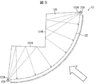
- FIG. 5 is a plan view of the lighting device 12 included in the display device 1.
- the display device 1 is a device for displaying a stereoscopic image inside the light guide plate 11 or in a space other than the light guide plate 11. In this case, as shown in FIG. 4, the display device 1 includes a light guide plate 11 and a lighting device 12.
- the display device 1 according to the present embodiment can be applied to the tail lamp 1A of the vehicle C.
- the light emitting surface 11B of the light guide plate 11 has a curved surface.
- the light guide plate 11 displays the stereoscopic image I by changing the optical path of the parallel light (see FIG. 5) incident from the incident surface 11A by the optical path changing unit group (optical path changing unit) 113 formed in the light guide plate 11. It is a member to be used.
- the lighting device 12 includes a light source 22 and a light guide member 120.
- the lighting device 12 is a device for providing the light guide plate 11 with parallel light necessary for forming the stereoscopic image I.
- the light guide member 120 is a member for converting diffused light from the light source 22 into parallel light by making the light incident on the exit surface 122 at a constant angle of incidence.
- the light guide member 120 can convert the light from the light source 22 into parallel light in which the incident angle incident on the exit surface 122 made of a curved surface travels in a constant direction.
- the light guide member 120 can convert the light from the light source 22 into parallel light traveling in a direction perpendicular to the exit surface 122 formed of a curved surface.
- the lighting device 12 provided with the light guide member 120 can provide parallel light necessary for imaging the stereoscopic image I to the light guide plate 11 having a curved surface. Therefore, the display device 1 can form a stereoscopic image as intended.
- the specific configurations of the light guide plate 11 and the lighting device 12 will be described in detail below.
- FIG. 4 is a perspective view of the display device 1 according to the present embodiment.
- the display device 1 includes a lighting device 12, a connecting portion 33, and a light guide plate 11.
- the display device 1 is arranged so that the convex surface of the light guide plate 11 forms a part of the outer surface of the vehicle C. That is, the lighting device 12 is stored inside the vehicle C.
- the lighting device 12 is a device for emitting light (hereinafter, also referred to as parallel light) parallel to the incident surface 11A (see FIG. 2) of the light guide plate 11 described later to the light guide plate 11. Is. Details of the configuration of the lighting device 12 will be described later.
- the connecting portion 33 is a portion that connects the lighting device 12 and the light guide plate 11, and is formed of a transparent resin material such as a polycarbonate resin or a polymethylmethacrylate resin.
- the connecting portion 33 connects the lighting device 12 and the light guide plate 11 so that the traveling direction of the light emitted from the lighting device 12 and the traveling direction of the light in the light guide plate 11 are, for example, substantially vertical. ..
- the connecting portion 33 has a curvature with respect to the traveling direction of the light emitted from the lighting device 12, and the traveling direction can be changed.
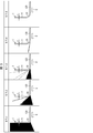
- FIG. 3 is a diagram for explaining the connection portion 33 of the display device 1.
- R is the radius of curvature of the connecting portion 33
- T is the thickness of the light guide plate 11.
- FIG. 3 shows the difference in the degree of light leakage due to the difference in the value obtained by dividing R by T.
- the arrow E indicates the traveling direction of the light emitted from the lighting device 12.
- the filled portion in each figure in FIG. 3 represents the light leaked from the connecting portion 33.
- the larger the curvature of the connecting portion 33 (the smaller the radius of curvature R), the greater the leakage of light from the connecting portion 33.
- the R / T value is 3 or more, the leakage of light from the connection portion 33 is sufficiently reduced.
- the R / T value is 5 or more, light does not leak from the connection portion 33.
- the light guide plate 11 is a member that deflects parallel light emitted from the lighting device 12 and incident inside the light guide plate 11 inside the light guide plate 11 and emits light from the light emitting surface 11B of the light guide plate 11.
- a material for forming the light guide plate 11 for example, a polycarbonate resin, a polymethyl methacrylate resin, or the like can be used.
- a plurality of optical path changing unit groups 113 are formed on the back surface 11D of the light guide plate.
- the optical path changing portion group 113 is continuously formed along a line parallel to the incident surface 11A and the back surface 11D.
- Each optical path changing portion included in the optical path changing portion group 113 is formed by a part of a Fresnel lens, and the convergence points of the respective optical path changing portions are different from each other.
- a virtual image as a stereoscopic image I is formed by a collection of convergence points of each optical path changing portion. That is, in the display device 1, light is incident on the light guide plate 11 from the lighting device 12, and the optical path is deflected and emitted by the optical path changing unit group 113 formed on the light guide plate 11, thereby forming a stereoscopic image I. Can be made to. As a result, information can be provided to the observer outside the vehicle C, and functions as a tail lamp and a brake lamp of the vehicle C.
- the display device 1 forms a stereoscopic image I in the space inside the vehicle C rather than the light guide plate 11.
- the brake lamp and the tail lamp can have a sense of depth.
- FIG. 5 is a plan view of the lighting device 12 included in the display device 1.
- the lighting device 12 includes a light source 22 (in the following description, the light source 22A and the light source 22B may be referred to in order to distinguish the light source 22) and a light guide member 120.
- the light source 22 is a light source that causes light to enter the light guide member 120.
- the light source 22 is, for example, an LED (Light Emitting diode) light source.
- the light source 22 may be a monochromatic LED light source or a combination of three types of LED light sources that emit red, green, and blue.
- the light source 22 has three-color LED light sources, various colors of light can be emitted by adjusting the intensity of the light emitted from each LED light source. Thereby, the color of the stereoscopic image I can be changed according to the application.
- the light guide member 120 is a member for converting diffused light incident from the light source 22 into parallel light and emitting it.
- the light guide member 120 has an incident surface 123 (123A and 123B), a reflecting surface 121 (121A and 121B), and an emitting surface 122.
- a transparent resin material such as a polycarbonate resin or a polymethylmethacrylate resin can be used.
- the incident surface 123A and the incident surface 123B are surfaces on which light from the light source 22A and the light source 22B is incident, respectively.
- the reflecting surface 121A and the reflecting surface 121B are surfaces for reflecting the light incident from the incident surfaces 123A and 123B in the direction perpendicular to the emitting surface 122, respectively.
- the reflecting surface 121 has a planar structure and can function as a total reflecting surface. In this case, at least a part of the light incident from the incident surface 123 is reflected by total reflection. That is, the reflecting surface 121 can suppress the divergence of the light incident from the incident surface 123, and the angle of the light incident on the emitting surface can be made constant.
- the amount of light reflected by total internal reflection depends on the absolute refractive index of the light guide member 120 and the angle of light incident on the reflecting surface 121.
- a reflective layer can be formed on the reflective surface 121 by metal deposition or the like.
- the formation of the reflective layer is not limited to metal vapor deposition, and may be formed by a method such as sputtering or painting.
- the exit surface 122 is a surface that emits light reflected by the reflection surface 121.
- the direction parallel to the incident surface 123, the reflecting surface 121, and the emitting surface 122 (the direction perpendicular to the paper surface in FIG. 5) will be described as the thickness direction.
- the emission surface 122 is an arc centered on a point where the light rays intersect when the light rays incident on the emission surface 122 are extended in the direction of the reflection surface 121 in a cross section perpendicular to the thickness direction. It forms a part.
- the direction perpendicular to the exit surface described above is a direction (normal direction) perpendicular to the tangent line of the arc.
- the traveling path of light in the lighting device 12 is shown by a broken line.
- the light emitted from the light source 22A is usually diffused light, is incident on the light guide member 120 from the incident surface 123A, and reaches the reflecting surface 121A.
- the light that reaches the reflecting surface 121A is reflected by the reflecting surface 121A.
- the light source 22A is arranged so that a point that is point-symmetric with respect to the reflection surface 121A in a cross section perpendicular to the thickness direction coincides with the center point of the arc.
- the light reflected by the reflecting surface 121A travels in the direction perpendicular to the emitting surface 122 in the cross section perpendicular to the thickness direction, and is emitted from the emitting surface 122. That is, the light emitted by the light source 22 is converted into parallel light by the lighting device 12 and emitted. The same applies to the light emitted from the light source 22B.
- FIG. 6 is a diagram showing a traveling path of light emitted from the lighting device 12 in the light guide plate 11, and is a view of the light guide plate 11 viewed from the direction of the arrow shown in FIG. In FIG. 6, the traveling path of light is shown by a broken line.
- the light emitted from the exit surface 122 enters the light guide plate 11 as parallel light in the direction perpendicular to the incident surface 11A of the light guide plate 11 via the connecting portion 33, and travels in the light guide plate 11.
- the light guide member 120 in the present embodiment includes (1) an incident surface 123 on which the light from the light source 22 is incident, and (2) a reflecting surface 121 that reflects the light incident from the incident surface 123. 3) It is composed of a curved surface, and is provided with an exit surface 122 that emits light reflected by the reflection surface 121.
- the reflecting surface 121 reflects the light incident from the light source 22 in a direction perpendicular to the emitting surface 122.
- the light from the light source 22 is reflected by the reflecting surface 121 and travels in a direction perpendicular to the emitting surface 122 having a curved surface. That is, the light guide member 120 can convert the light from the light source 22 into parallel light.
- the reflecting surface 121 reflects the light incident from the light source 22 in the direction perpendicular to the emitting surface 122. According to the above configuration, the light guide member 120 can convert the light from the light source 22 into parallel light.
- the curved surface when the curved surface has a thickness direction parallel to the incident surface 123, the reflecting surface 121, and the emitting surface 122, the curved surface has a cross-sectional shape perpendicular to the thickness direction. It is an arc.
- the reflecting surface 121 is a plane arranged so that a point symmetrical with respect to the reflecting surface 121 of the light source 22 coincides with the center point of the arc in the cross-sectional shape perpendicular to the thickness direction. According to the above configuration, since the reflecting surface 121 is flat, the light guide member 120 can be easily manufactured.
- the light guide member 120 in the present embodiment includes (1) an incident surface 123A and an incident surface 123B, and (2) a reflecting surface 121A and a reflecting surface 121B corresponding to the incident surface 123A and the incident surface 123B, respectively.
- the light reflected by the reflecting surface 121A and the reflecting surface 121B is emitted from different regions on the emitting surface 122, respectively.
- the incident surface 123A and the incident surface 123B can be arranged at positions close to the light guide plate 11.
- This structure guides the light source as compared with the case where the light source is arranged so as to be able to provide the light perpendicular to the exit surface 122 of the light guide member 120 (for example, when the light source is arranged at the center point of the above arc).
- the depth of the optical member 120 (depth when viewed from the direction of the arrow in FIG. 3) can be shortened.
- the lighting device 12 in the present embodiment includes a light guide member 120 and a light source 22. According to the above configuration, the illuminating device 12 can provide parallel light collimated in a direction perpendicular to the incident surface 11A of the light guide plate 11.
- the display device 1 in the present embodiment guides the light incident from the lighting device 12 and the lighting device 12, reflects it by the optical path changing unit group 113 formed at a predetermined position, and emits the light from the light emitting surface 11B. It is provided with a light guide plate 11 for making the light guide plate 11.
- the light guide plate 11 forms an image in a space other than the light guide plate 11 by the light emitted from the light emitting surface 11B.
- the display device 1 can form an image of the stereoscopic image I as intended (in other words, a clear stereoscopic image I can be formed).
- the light guide plate 11 may display a flat image inside the light guide plate 11 by the light emitted from the light emitting surface 11B. In this case, the display device 1 can display a flat image.
- the display device 1 configured as described above is easy to manufacture, has a simple and compact shape, and can provide the observer with a stereoscopic image I or a planar image.
- the light guide member may be configured to include the light guide member 130 and the connecting portion 33.
- the light guide member includes a light guide member 130 and a connecting portion 33 as an emission direction changing portion that changes the traveling direction of the light emitted from the emission surface 122 in a direction parallel to the thickness direction.
- the exit surface of the light guide member is the surface of the connecting portion 33 that is in contact with the light guide plate 11. According to the light guide member having the above configuration, parallel light can be emitted in a direction parallel to the thickness direction.
- the display device 1 is applied as the tail lamp 1A of the vehicle C is illustrated, but the present invention is not limited to this application.
- the display device 1 can also be applied to, for example, a game machine, a vehicle display device, an aerial switch, and the like.
- a stereoscopic image I may be imaged by a light guide plate 11 as at least one switch among a plurality of switches in a user-operated operation panel.
- the stereoscopic image I may be imaged by the light guide plate 11 in a device for displaying a speedometer or the like.
- an aerial switch for example, a stereoscopic image I may be imaged by a light guide plate 11 by being used in an input unit of an elevator.
- FIG. 7 is a perspective view showing the display device 2. As shown in FIG. 7, the display device 2 includes a lighting device 13, a connecting portion 33, and a light guide plate 11.
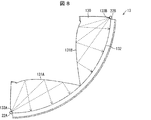
- FIG. 8 is a plan view of the lighting device 13 included in the display device 2.
- the lighting device 13 includes a light source 22 (light source 22A and light source 22B) and a light guide member 130.
- the light guide member 130 has an incident surface 133 (incident surface 133A and incident surface 133B), a reflecting surface 131 (reflecting surface 131A and reflecting surface 131B), and an emitting surface 132.
- the light guide member 130 is different from the light guide member 120 in that the reflecting surfaces 131 (131A and 131B) have a curved surface structure. Further, the exit surface 132 of the lighting device 13 forms a part of an arc. In the lighting device in this modification, the exit surface of the lighting device may be a curved surface other than an arc in a cross section perpendicular to the thickness direction.
- the reflective surface 131A and the reflective surface 131B are curved surfaces that are concave with respect to the exit surface 132.
- the reflective surface 131 can function as a total reflective surface. In this case, at least a part of the light incident from the incident surface 133 is reflected by total reflection.
- the amount of light reflected by total internal reflection depends on the absolute refractive index of the light guide member 130 and the angle of light incident on the reflecting surface 121. When the amount of light reflected by total reflection is small, metal vapor deposition can be applied to the reflecting surface 121.
- the reflecting surface 131A and the reflecting surface 131B are composed of a plurality of surfaces that reflect the light incident from the incident surface 133 at different angles, and can be configured by, for example, a Fresnel lens.
- the diffused light emitted from the light source 22A and the light source 22B enters the light guide member 130 from the incident surface 133A and the incident surface 133B and reaches the reflecting surface 131A and the reflecting surface 131B.
- the light that has reached the reflecting surface 131A and the reflecting surface 131B is reflected by the plurality of surfaces and is reflected in a direction perpendicular to the emitting surface 132, and is emitted from the emitting surface 132. That is, the light emitted by the light source 22 is converted into parallel light by the light guide member 130 and emitted.
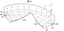
- FIG. 9 is a perspective view of the display device 2.
- the traveling path of the light emitted from the light source 22A and the light source 22B in the display device 2 is shown by a broken line.
- the light emitted from the light emitting surface 132 of the light guide member 130 perpendicularly to the light emitting surface 132 passes through the connecting portion 33 and is incident surface of the light guide plate 11 (not shown). It is incident on the light guide plate 11 as parallel light in the direction perpendicular to the light guide plate 11.
- the lighting device 13 can provide collimated parallel light with respect to the light guide plate 11.
- the reflecting surface 131 of the light guide member 130 has a curved line in a cross section perpendicular to the thickness direction, it is possible to provide continuous light without dark lines to the emitting surface 132. Further, since the illuminating device 13 has the reflecting surface 131, the depth can be shortened for the same reason as the illuminating device 12 of the first embodiment.
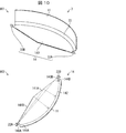
- Reference numeral 901 in FIG. 10 is a perspective view showing a display device 3 as a modification of the display device 1 in the first embodiment.
- the display device 3 includes a lighting device 14, a connecting portion 33, and a light guide plate 11.
- Reference numeral 902 in FIG. 10 is a plan view of the lighting device 14 included in the display device 3.
- the lighting device 14 includes two light sources 22 (light source 22A and light source 22B) and a light guide member 140.
- the light guide member 140 has an incident surface 143 (143A and 143B), a reflecting surface 141 (141A and 141B), and an emitting surface 142.
- the light guide member 140 differs from the light guide member 120 in that the shape of the reflection surface formed by the two reflection surfaces 141A and 141B is concave with respect to the exit surface 142. .. Further, a light limiting portion 144A and a light limiting portion 144B are formed between the incident surface 143A and the incident surface 143B and the light guide member 140, respectively.
- the light limiting portions 144A and 144B have an elongated shape at the end of the light guide member 140, and play a role of limiting the light guide angle of the light incident from the incident surface 143.
- the light limiting unit 144A and the light limiting unit 144B have a range of light emitted from the light sources 22A and 22B so that the light emitted from the light source 22A and the light source 22B is irradiated only to the corresponding reflecting surface 141. To limit each.
- the light limiting unit 144 configured in this way, it is possible to prevent the light source 22A and the light source 22B from irradiating the reflecting surface other than the corresponding reflecting surface 141. This makes it possible to prevent the generation of stray light.
- the reflecting surface 141A and the reflecting surface 141B each have a flat structure and can function as a total reflecting surface. In this case, at least a part of the light incident from the incident surface 143 is reflected by total reflection. The amount of light reflected by total internal reflection depends on the absolute refractive index of the light guide member 140 and the angle of light incident on the reflecting surface 141. When the amount of light reflected by total reflection is small, metal vapor deposition can be applied to the reflecting surface 121. As shown by the broken line in FIG. 10, the diffused light emitted from the light source 22A and the light source 22B enters the light guide member 140 from the incident surface 143A and the incident surface 143B and reaches the reflecting surface 141A and the reflecting surface 141B.
- the light that has reached the reflecting surface 141A and the reflecting surface 141B is reflected in the direction perpendicular to the emitting surface 142 and is emitted from the emitting surface 142. That is, the light emitted by the light source 22 is converted into parallel light by the light guide member 140 and emitted.
- the light guide member 140 in the present embodiment has the incident surface 143A and the incident surface 143B so that the light incident from the incident surface 143A and the incident surface 143B is irradiated only to the corresponding reflecting surface 141A and 141B, respectively. It includes a light limiting unit 144A and a light limiting unit 144B that limit the range of light incident from the incident surface 143B.
- the light guide member 140 can be prevented from generating stray light by providing the light limiting unit 144. Further, according to the above configuration, the light from the light source 22 is reflected once by the reflecting surface 121 and converted into parallel light by making the light traveling in the direction perpendicular to the emitting surface 122 having a curved surface. can do.
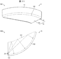
- Reference numeral 1001 in FIG. 11 is a perspective view showing a display device 4 as a modification of the display device 1.
- the display device 4 includes a lighting device 15, a connecting portion 33, and a light guide plate 11.
- Reference numeral 1002 in FIG. 11 is a plan view of the lighting device 15 included in the display device 4.
- the lighting device 15 includes a light source 22 and a light guide member 150.
- the light guide member 150 has an incident surface 153, a reflecting surface 151, and an emitting surface 152.
- the light guide member 150 is different from the light guide member 120 in that it has one light source 22 and the shape of the reflection surface 151 is different from that of the light guide member 120.
- the reflecting surface 151 is composed of a curved surface that is convex with respect to the incident direction of the light from the light source 22.
- the shape of the curved surface is such that the light incident from the light source 22 is reflected in the direction perpendicular to the exit surface 152. Further, the distance until the light reflected by the reflecting surface 151 reaches the emitting surface 152 becomes shorter as the position where the light is reflected by the reflecting surface 151 becomes distal to the light source 22.
- the reflecting surface 151 is formed so that a straight line connecting an arbitrary point of the reflecting surface 151 and the light source 22 intersects the reflecting surface 151 only at the above-mentioned arbitrary point.
- the reflection surface 151 is designed so that the end portion facing the light source 22 has a short distance between the reflection surface 151 and the emission surface 152.
- the reflection surface 151 can function as a total reflection surface. In this case, at least a part of the light incident from the incident surface 153 is reflected by total reflection. The amount of light reflected by total internal reflection depends on the absolute refractive index of the light guide member 150 and the angle of light incident on the reflecting surface 151. When the amount of light reflected by total reflection is small, metal vapor deposition can be applied to the reflecting surface 151.
- the diffused light emitted from the light source 22 enters the light guide member 150 from the incident surface 153 and reaches the reflecting surface 151.
- the light that has reached the reflecting surface 151 is reflected in the direction perpendicular to the emitting surface 152 and is emitted from the emitting surface 152. That is, the light emitted by the light source 22 is converted into parallel light by the light guide member 160 and emitted.
- the light guide member 150 in the present embodiment includes only one incident surface 153.
- the light guide member 150 can avoid interference with other light sources.
- the illuminating device 15 can provide collimated parallel light with respect to the light guide plate 11. Further, since the illuminating device 15 has the reflecting surface 151, the depth can be shortened for the same reason as the illuminating device 12 of the first embodiment.
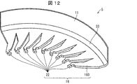
- FIG. 12 is a perspective view showing a display device 5 as a modification of the display device 1.
- the display device 5 includes a lighting device 16, a connecting portion 33, and a light guide plate 11.
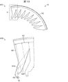
- FIG. 13 is a plan view of the lighting device 15 included in the display device 5.
- Reference numeral 1201 in FIG. 13 indicates an overall view of the lighting device 16, and reference numeral 1202 is an enlarged view of a portion surrounded by a frame P in reference numeral 1201.
- the lighting device 16 includes a light source 22 and a light guide member 160.
- the light guide member 160 has an incident surface 163, a first reflecting surface 161A, a second reflecting surface 161B, and an emitting surface 162.
- the light guide member 150 differs from the light guide member 120 in that the light guide member unit having one incident surface (the portion shown by reference numeral 1202 in FIG. 13) has a continuous shape. Further, the light guide member unit is different from the light guide member 120 in that it has a first reflection surface 161A and a second reflection surface 161B, respectively.
- the first reflecting surface 161A is a surface for reflecting the light incident from the incident surface 163 toward the second reflecting surface 161B.
- the second reflecting surface 161B is a surface for reflecting the light reflected by the first reflecting surface 161A in a direction perpendicular to the emitting surface 162.
- the first reflecting surface 161A can function as a total reflecting surface. In this case, at least a part of the light incident from the incident surface 163 is reflected by total reflection.
- the second reflecting surface 161B is composed of a curved surface that is concave with respect to the incident direction of the light reflected by the first reflecting surface 161A. The shape of the curved surface is formed so that the light reflected by the first reflecting surface 161A is reflected in the direction perpendicular to the emitting surface in the cross section perpendicular to the thickness direction.
- the second reflecting surface 161B can function as a total reflecting surface. In this case, at least a part of the light reflected by the first reflecting surface 161A is reflected by total reflection.
- the amount of light reflected by the total reflection depends on the absolute refractive index of the light guide member 160 and the angle of the light incident on the first reflecting surface 161A and the second reflecting surface 161B. Dependent. When the amount of light reflected by total reflection is small, metal deposition can also be applied to the first reflecting surface 161A and / or the second reflecting surface 161B.
- the diffused light emitted from the light source 22 enters the light guide member 150 from the incident surface 163, reaches the first reflecting surface 161A, and reaches the first reflecting surface 161B of the second reflecting surface 161B. Reflected in the direction.
- the light reflected by the first reflecting surface 161A is reflected by the second reflecting surface 161B in a direction perpendicular to the emitting surface 162, and is emitted from the emitting surface 162. That is, the light emitted by the light source 22 is converted into parallel light by the light guide member 160 and emitted.
- the lighting device 15 can provide collimated parallel light with respect to the light guide plate 11.
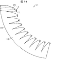
- FIG. 14 is a plan view showing a lighting device 17 according to a modified example of the light guide member 120.
- the lighting device 17 includes a light guide member 170 instead of the light guide member 160 described above.
- the light guide member 170 has an incident surface 173, a reflecting surface 171 and an emitting surface 172.
- the light guide member 170 differs from the light guide member 120 in that the light guide member units having one incident surface 173 have a continuous shape. Further, the light guide member unit is different from the light guide member 160 in that light is reflected in a direction perpendicular to the exit surface 172 by one reflection by the reflection surface 171.
- the reflection surface 171 is composed of a curved surface that is concave with respect to the incident direction of the light emitted from the light source 22 and incident from the incident surface 173.
- the shape of the curved surface is such that the light reflected by the reflecting surface 171 is reflected in the direction perpendicular to the emitting surface 172.
- the reflecting surface 171 can function as a total reflecting surface. In this case, at least a part of the light reflected by the reflecting surface 171 is reflected by total reflection.
- the amount of light reflected by total internal reflection depends on the absolute refractive index of the light guide member 170 and the angle of light incident on the reflecting surface 171. When the amount of light reflected by total reflection is small, metal vapor deposition can be applied to the reflecting surface 171.
- the diffused light incident on the light guide member 170 from the incident surface 173 is reflected by the reflecting surface 171 in the direction perpendicular to the emitting surface 172 and emitted from the emitting surface 172. ..
- the light emitted by the light source 22 is converted into parallel light by the light guide member 170 and emitted.
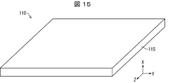
- FIG. 15 is a perspective view of the light guide plate 110.
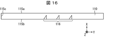
- FIG. 16 is a cross-sectional view showing the configuration of the light guide plate 110.
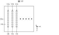
- FIG. 17 is a plan view showing the configuration of the light guide plate 110.
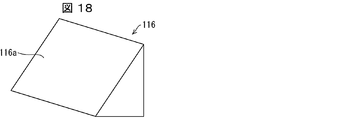
- FIG. 18 is a perspective view showing the configuration of the optical path changing portion 116 included in the light guide plate 110.
- the light guide plate 110 is a member that guides light (incident light) incident from a lighting device (not shown).
- the light guide plate 110 is made of a transparent resin material having a relatively high refractive index.
- a polycarbonate resin, a polymethyl methacrylate resin, or the like can be used as the material for forming the light guide plate 110.
- the light guide plate 110 is formed of a polymethylmethacrylate resin.
- the light guide plate 110 includes an emitting surface 115a (light emitting surface), a back surface 115b, and an incident surface 115c.
- the exit surface 115a is a surface that guides the inside of the light guide plate 110 and emits light whose optical path has been changed by the optical path changing unit 116 described later.
- the exit surface 115a constitutes the front surface of the light guide plate 110.
- the back surface 115b is a surface parallel to the exit surface 115a, and is a surface on which the optical path changing portion 116, which will be described later, is arranged.
- the incident surface 115c is a surface on which the light emitted from the lighting device (not shown) is incident on the inside of the light guide plate 110.
- the light incident on the light guide plate 110 from the incident surface 115c is totally reflected by the exit surface 115a or the back surface 115b, and is guided through the light guide plate 110.
- the optical path changing portion 116 is formed on the back surface 115b inside the light guide plate 110, and is for changing the optical path of the light guided in the light guide plate 110 and emitting the light from the exit surface 115a. It is a member. A plurality of optical path changing portions 116 are provided on the back surface 115b of the light guide plate 110.
- the optical path changing portion 116 is provided along the direction parallel to the incident surface 115c.
- the optical path changing portion 116 has a triangular pyramid shape and includes a reflecting surface 116a that reflects (totally reflected) the incident light.
- the optical path changing portion 116 may be, for example, a recess formed in the back surface 115b of the light guide plate 110. Further, the optical path changing portion 116 is not limited to the triangular pyramid shape.
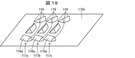
- a plurality of optical path changing unit groups 117a, 117b, 117c ... Consisting of a plurality of optical path changing units 116 are formed on the back surface 115b of the light guide plate 110.
- FIG. 19 is a perspective view showing the arrangement of the optical path changing portions 116.
- the reflecting surfaces 116a of the plurality of optical path changing units 116 are arranged on the back surface 115b of the light guide plate 110 so that the angles with respect to the incident direction of the light are different from each other. Has been done.
- each optical path changing unit group 117a, 117b, 117c ... changes the optical path of the incident light and emits the incident light from the emitting surface 115a in various directions.
- a method of forming a stereoscopic image I by the light guide plate 110 will be described with reference to FIG.
- a case will be described in which a stereoscopic image I as a surface image is formed on the stereoscopic image forming surface P which is a plane perpendicular to the exit surface 115a of the light guide plate 110 by the light whose optical path is changed by the optical path changing unit 116. ..
- FIG. 20 is a perspective view showing a method of forming a stereoscopic image I by the light guide plate 110.
- a ring mark with diagonal lines is formed as a stereoscopic image I on the stereoscopic image forming surface P.
- the light whose optical path is changed by each optical path changing unit 116 of the optical path changing unit group 117a intersects the stereoscopic image imaging surface P at the line La1 and the line La2.
- the line image LI which is a part of the stereoscopic image I, is formed on the stereoscopic image forming surface P.
- the line image LI is a line image parallel to the YZ plane.
- the line image LI of the line La1 and the line La2 is formed by the light from a large number of optical path changing units 116 belonging to the optical path changing unit group 117a.
- the light for forming the images of the line La1 and the line La2 may be provided by at least two optical path changing units 116 in the optical path changing unit group 117a.
- each optical path changing unit 116 of the optical path changing unit group 117b intersects the stereoscopic image imaging surface P at the line Lb1, the line Lb2, and the line Lb3.
- the line image LI which is a part of the stereoscopic image I, is formed on the stereoscopic image forming surface P.
- each optical path changing unit 116 of the optical path changing unit group 117c intersects the stereoscopic image imaging surface P at the line Lc1 and the line Lc2.
- the line image LI which is a part of the stereoscopic image I, is formed on the stereoscopic image forming surface P.
- the positions of the line images LI formed by the optical path changing unit groups 117a, 117b, 117c ... In the X-axis direction are different from each other.
- the distance in the X-axis direction of the line image LI imaged by each optical path changing unit group 117a, 117b, 117c ... It can be made smaller.
- a stereoscopic image I which is a surface image, is formed on the stereoscopic image forming surface P.
- the stereoscopic image forming surface P may be a plane perpendicular to the X axis, a plane perpendicular to the Y axis, or a plane perpendicular to the Z axis. Further, the stereoscopic image forming surface P may be a plane that is not perpendicular to the X-axis, the Y-axis, or the Z-axis. Further, the stereoscopic image forming surface P may be a curved surface instead of a flat surface. That is, the light guide plate 110 can form a stereoscopic image I on an arbitrary surface (plane and curved surface) in space by the optical path changing unit 116. In addition, a three-dimensional image can be formed by combining a plurality of surface images.
- the light guide member is composed of an incident surface on which light from a light source is incident, at least one reflecting surface that reflects light incident from the incident surface, and a curved surface, and is reflected by the reflecting surface.
- the reflecting surface includes an emitting surface for emitting the light, and the reflecting surface reflects the light incident from the light source in a direction in which the incident angle incident on the emitting surface is constant.
- the light from the light source is reflected by the reflecting surface and travels in the direction having a constant incident angle with respect to the emitting surface having a curved surface. That is, the light guide member can convert the light from the light source into parallel light.
- the reflecting surface reflects light incident from the light source in a direction perpendicular to the emitting surface.
- the light from the light source is reflected by the reflecting surface and travels in the direction perpendicular to the exit surface having a curved surface. That is, the light guide member can convert the light from the light source into parallel light.
- the reflecting surface is composed of a plurality of surfaces that reflect light incident from the incident surface at different angles.
- the curved surface has a cross-sectional shape perpendicular to the thickness direction when the direction parallel to the entrance surface, the reflection surface, and the emission surface is the thickness direction.
- the reflecting surface is arranged so that the point symmetrical with respect to the reflecting surface of the light source coincides with the center point of the arc in the cross-sectional shape perpendicular to the thickness direction. It is a plane.
- the light guide member since the reflecting surface is flat, the light guide member can be easily manufactured.
- the light guide member includes a plurality of the incident surfaces and a plurality of the reflecting surfaces corresponding to the plurality of light sources, and the light reflected by the respective reflecting surfaces can be generated. It is emitted from different regions on the exit surface.
- the incident surface can be arranged at a position close to the light guide plate, and the depth of the light guide member can be shortened.
- the light guide member according to one aspect of the present invention limits the range of light incident from the incident surface so that the light incident from the plurality of incident surfaces is irradiated only to the corresponding reflecting surface. It has a part. According to the above configuration, it is possible to prevent the occurrence of stray light.
- a reflective layer is formed on at least a part of the reflective surface. According to the above configuration, it is possible to form a reflective surface having a desired function.
- the reflective surface is formed so that a straight line connecting an arbitrary point on the reflective surface and the light source intersects the reflective surface only at the arbitrary point. ing.
- all the light emitted from the light source can be applied to the reflecting surface, so that the light can be emitted in all the regions of the emitting surface in the cross section perpendicular to the thickness direction.
- the light guide member according to one aspect of the present invention includes only one incident surface, and the distance until the light reflected by the reflecting surface reaches the emitting surface is such that the light is on the reflecting surface.
- the position of reflection becomes shorter as it becomes distal to the light source.
- the depth of the light guide member can be shortened.
- the reflecting surface is fully reflected by the first reflecting surface that totally reflects at least a part of the light incident from the incident surface and the first reflecting surface. It consists of a second reflecting surface that totally reflects at least a part of the light.
- the reflective surface can reflect incident light without the need to form a reflective layer by metal deposition or the like.
- the lighting device includes the above-mentioned light guide member and at least one light source.
- the illuminating device can provide parallel light collimated in a direction having a constant incident angle with respect to the incident surface of the light guide plate.
- the display device guides the above-mentioned lighting device and the light incident from the lighting device, reflects it by an optical path changing portion formed at a predetermined position, and emits the light from the light emitting surface. It is provided with a light guide plate to be used. According to the above configuration, the display device can form a stereoscopic image or a planar image as intended.
- the display device further includes a connecting portion between the lighting device and the light guide plate that changes the traveling direction of light emitted from the lighting device, and the connecting portion is provided. , Has a curvature in the traveling direction of the light emitted from the lighting device.
- the direction in which the light reflected by the reflecting surface is guided and the direction in which the light travels in the light guide plate can be different.
- the value obtained by dividing the radius of curvature of the curvature by the thickness of the light guide plate is 3 or more.
- the light whose traveling direction is changed at the connection portion can be incident on the light guide plate without leaking to the outside at the connection portion.
- the light guide plate forms an image in a space other than the light guide plate by the light emitted from the light emitting surface. According to the above configuration, the display device can form a stereoscopic image as intended.
- the light guide plate displays a flat image inside the light guide plate by the light emitted from the light emitting surface. According to the above configuration, the display device can display a flat image.
Landscapes
- Physics & Mathematics (AREA)
- Engineering & Computer Science (AREA)
- General Physics & Mathematics (AREA)
- General Engineering & Computer Science (AREA)
- Optics & Photonics (AREA)
- Theoretical Computer Science (AREA)
- Business, Economics & Management (AREA)
- Accounting & Taxation (AREA)
- Marketing (AREA)
- Microelectronics & Electronic Packaging (AREA)
- Light Guides In General And Applications Therefor (AREA)
- Planar Illumination Modules (AREA)
- Illuminated Signs And Luminous Advertising (AREA)
Abstract
Description
まず、図1~5を用いて、本発明が適用される場面の一例について説明する。図1は、本発明の一実施形態に係る表示装置1の適用場面の一例を示している。図2は、表示装置1が備える導光板11を、車両Cの外側にいる観察者から見た図である。図3は、実施形態1に係る表示装置1の接続部33について説明するための図である。図4は、表示装置1の斜視図である。図5は、表示装置1が備える照明装置12の平面図である。表示装置1は、導光板11の内部または導光板11以外の空間に立体画像を表示させるための装置である。この場合、表示装置1は、図4に示すように、導光板11と照明装置12とを備える。本実施形態に係る表示装置1は、図1に示すように、車両Cのテールランプ1Aに適用することができる。
〔実施形態1〕
(表示装置1の構成)
図2~図5を用いて、本実施形態に係る例示的な表示装置1および照明装置12について説明する。図4は、本実施形態に係る表示装置1の斜視図である。図4に示すように、表示装置1は、照明装置12と、接続部33と、導光板11とを備える。表示装置1は、導光板11の凸面が、車両Cの外表面の一部を形成するように配置される。つまり、照明装置12は、車両Cの内側に格納される。
図5は、表示装置1が備える照明装置12の平面図である。図5に示すように、照明装置12は、光源22(以降の説明では、光源22を区別するために光源22Aおよび光源22Bと呼称する場合がある)と、導光部材120とを備える。
次に、光源22から出射された光の進行経路について、図5および図6を参照しながら説明する。
以上のように、本実施形態における導光部材120は、(1)光源22からの光が入射する入射面123と、(2)入射面123から入射した光を反射させる反射面121と、(3)曲面からなり、反射面121で反射された光を出射する出射面122とを備えている。反射面121は、光源22から入射した光を、出射面122に対して垂直な方向に反射させる。
以上、本発明の実施の形態を詳細に説明してきたが、前述までの説明はあらゆる点において本発明の例示に過ぎない。本発明の範囲を逸脱することなく種々の改良や変形を行うことができることは言うまでもない。例えば、以下のような変更が可能である。なお、以下では、上記実施形態と同様の構成要素に関しては同様の符号を用い、上記実施形態と同様の点については、適宜説明を省略した。以下の変形例は適宜組み合わせ可能である。
表示装置1の変形例としての表示装置2について、図7~9を用いて説明する。図7は、表示装置2を示す斜視図である。図7に示すように、表示装置2は、照明装置13と、接続部33と、導光板11とを備える。
図10の符号901は、実施形態1における表示装置1の変形例としての表示装置3を示す斜視図である。図10に示すように、表示装置3は、照明装置14と、接続部33と、導光板11とを備える。
図11の符号1001は、表示装置1の変形例としての表示装置4を示す斜視図である。図11に示すように、表示装置4は、照明装置15と、接続部33と、導光板11とを備える。
図12は、表示装置1の変形例としての表示装置5を示す斜視図である。図12に示すように、表示装置5は、照明装置16と、接続部33と、導光板11とを備える。
図14は、導光部材120の変形例に係る照明装置17を示す平面図である。図14に示すように、照明装置17は、上記の導光部材160に代えて導光部材170を備えている。導光部材170は、入射面173と、反射面171と、出射面172とを有している。
表示装置1の変形例としての導光板110について、図15~図20を参照しながら説明する。
本発明の一態様に係る導光部材は、光源からの光が入射する入射面と、前記入射面から入射した光を反射させる少なくとも1つの反射面と、曲面からなり、前記反射面で反射された光を出射する出射面とを備え、前記反射面は、前記光源から入射した光を、前記出射面に入射する入射角度が一定となる方向に反射させる。
12~17 照明装置
11、110 導光板
22 光源
120、130、140、150、160、170 導光部材
113、116、117 光路変更部(光路変更部群)
116a、121、131、141、151、161、171 反射面
115a、122、132、142、152、162、172 出射面
11A、115c、123、133、143、153、163、173 入射面
144 光制限部
Claims (16)
- 光源からの光が入射する入射面と、
前記入射面から入射した光を反射させる少なくとも1つの反射面と、
曲面からなり、前記反射面で反射された光を出射する出射面とを備え、
前記反射面は、前記光源から入射した光を、前記出射面に入射する入射角度が一定となる方向に反射させる、導光部材。 - 前記反射面は、前記光源から入射した光を前記出射面に対して垂直な方向に反射させる、請求項1に記載の導光部材。
- 前記反射面は、前記入射面から入射した光を互いに異なる角度で反射する複数の面からなっている、請求項1または2に記載の導光部材。
- 前記曲面は、前記入射面、前記反射面、および、前記出射面に平行な方向を厚み方向とした場合、前記厚み方向に垂直な断面形状において、円弧となっており、
前記反射面は、前記厚み方向に垂直な断面形状において、前記光源について前記反射面に対して点対称となる点が前記円弧の中心点と一致するように配置される平面である、請求項1または2に記載の導光部材。 - 複数の前記入射面と、
複数の前記入射面にそれぞれ対応する複数の前記反射面とを備え、
それぞれの前記反射面によって反射された光は、前記出射面におけるそれぞれ異なる領域から出射される、請求項1~4のいずれか1項に記載の導光部材。 - 複数の前記入射面から入射した光が対応する前記反射面にのみ照射されるように前記入射面から入射した光の範囲を制限する光制限部を備える、請求項5に記載の導光部材。
- 前記反射面の少なくとも一部に、反射層が形成されている、請求項1~6のいずれか1項に記載の導光部材。
- 前記反射面は、前記反射面の任意の点と前記光源とを結ぶ直線が、前記任意の点でのみ前記反射面と交わるように形成されている、請求項1から7のいずれか1項に記載の導光部材。
- 前記入射面を1つのみ備え、前記反射面で反射された光が前記出射面に到達するまでの距離は、前記光が前記反射面で反射される位置が前記光源から遠位になるほど短くなる、請求項1~3のいずれか1項に記載の導光部材。
- 前記反射面は、前記入射面から入射した光の少なくとも一部を全反射させる第1反射面と、前記第1反射面で全反射された光の少なくとも一部を全反射させる第2反射面からなる、請求項1または2に記載の導光部材。
- 請求項1から10のいずれか1項に記載の導光部材と、
少なくとも1つの光源とを備える、照明装置。 - 請求項11に記載の照明装置と、
前記照明装置から入射した光を導光し、所定の位置に形成された光路変更部によって反射させて光出射面から出射させる導光板とを備える、表示装置。 - 前記照明装置と、前記導光板との間に、前記照明装置から出射される光の進行方向を変更する接続部をさらに備え、
前記接続部は、前記照明装置から出射される光の進行方向に曲率を有している、請求項12に記載の表示装置。 - 前記曲率の曲率半径を前記導光板の厚さで割った値は3以上である、請求項13に記載の表示装置。
- 前記導光板は、前記光出射面から出射させる光により、当該導光板以外の空間に画像を結像させる請求項12~14のいずれか1項に記載の表示装置。
- 前記導光板は、前記光出射面から出射させる光により、前記導光板の内部に平面画像を表示する請求項12~14のいずれか1項に記載の表示装置。
Priority Applications (3)
| Application Number | Priority Date | Filing Date | Title |
|---|---|---|---|
| DE112021001617.2T DE112021001617B4 (de) | 2020-03-13 | 2021-01-26 | Lichtleiter, beleuchtungsvorrichtung und anzeigevorrichtung |
| US17/802,725 US12038595B2 (en) | 2020-03-13 | 2021-01-26 | Light guide member, lighting device, and display device |
| CN202180013267.2A CN115053098B (zh) | 2020-03-13 | 2021-01-26 | 导光部件、照明装置以及显示装置 |
Applications Claiming Priority (2)
| Application Number | Priority Date | Filing Date | Title |
|---|---|---|---|
| JP2020-044084 | 2020-03-13 | ||
| JP2020044084A JP7581636B2 (ja) | 2020-03-13 | 2020-03-13 | 導光部材、照明装置および表示装置 |
Publications (1)
| Publication Number | Publication Date |
|---|---|
| WO2021181917A1 true WO2021181917A1 (ja) | 2021-09-16 |
Family
ID=77671351
Family Applications (1)
| Application Number | Title | Priority Date | Filing Date |
|---|---|---|---|
| PCT/JP2021/002537 Ceased WO2021181917A1 (ja) | 2020-03-13 | 2021-01-26 | 導光部材、照明装置および表示装置 |
Country Status (5)
| Country | Link |
|---|---|
| US (1) | US12038595B2 (ja) |
| JP (1) | JP7581636B2 (ja) |
| CN (1) | CN115053098B (ja) |
| DE (1) | DE112021001617B4 (ja) |
| WO (1) | WO2021181917A1 (ja) |
Families Citing this family (1)
| Publication number | Priority date | Publication date | Assignee | Title |
|---|---|---|---|---|
| JPWO2025009160A1 (ja) * | 2023-07-06 | 2025-01-09 |
Citations (2)
| Publication number | Priority date | Publication date | Assignee | Title |
|---|---|---|---|---|
| US20030117789A1 (en) * | 2001-12-11 | 2003-06-26 | Nowak David R. | Lighting system |
| JP2007171636A (ja) * | 2005-12-22 | 2007-07-05 | Matsushita Electric Ind Co Ltd | 導光板構造 |
Family Cites Families (17)
| Publication number | Priority date | Publication date | Assignee | Title |
|---|---|---|---|---|
| JP3187280B2 (ja) | 1995-05-23 | 2001-07-11 | シャープ株式会社 | 面照明装置 |
| JP2002174732A (ja) * | 2000-12-07 | 2002-06-21 | Mark:Kk | 導光板およびそれを用いたディスプレイ装置ならびに電子装置、導光板の製造方法 |
| JP2004022175A (ja) | 2002-06-12 | 2004-01-22 | Enplas Corp | 面光源装置,画像表示装置及び導光体組立体 |
| WO2007145248A1 (ja) | 2006-06-16 | 2007-12-21 | Fujifilm Corporation | 導光板、導光板組立体、およびこれらを用いる面状照明装置、ならびに液晶表示装置 |
| JP2008123725A (ja) | 2006-11-08 | 2008-05-29 | Sharp Corp | 照明装置 |
| JP2010092685A (ja) | 2008-10-07 | 2010-04-22 | Fujifilm Corp | 導光板およびこれを備えた面状照明装置 |
| JP5562120B2 (ja) | 2010-05-21 | 2014-07-30 | スタンレー電気株式会社 | 車両用灯具ユニット |
| DE102013222794A1 (de) | 2013-11-08 | 2015-05-13 | Automotive Lighting Reutlingen Gmbh | Lichtleiter, Lichtleiterstruktur und Kfz-Beleuchtungseinrichtung |
| JP5979291B1 (ja) | 2015-07-29 | 2016-08-24 | オムロン株式会社 | 光デバイス |
| JP2017195163A (ja) * | 2016-04-22 | 2017-10-26 | 川崎重工業株式会社 | 導光板及び面照明装置 |
| US10240746B2 (en) * | 2016-07-14 | 2019-03-26 | Valeo North America, Inc. | Fiber optic light panel with homogeneous light output |
| JP6720809B2 (ja) | 2016-09-29 | 2020-07-08 | オムロン株式会社 | 導光部材、導光部材ユニットおよび照明装置 |
| CN110100321B (zh) * | 2016-12-29 | 2022-10-28 | 亮锐控股有限公司 | 包括透明结构的照明器件 |
| US12267921B2 (en) * | 2018-01-10 | 2025-04-01 | Quarkstar Llc | Luminaires for spatial dimming |
| JP7130913B2 (ja) | 2018-06-27 | 2022-09-06 | 日亜化学工業株式会社 | 光学装置および照明装置 |
| EP3671016A1 (de) * | 2018-12-21 | 2020-06-24 | ZKW Group GmbH | Beleuchtungsvorrichtung für einen kraftfahrzeugscheinwerfer sowie kraftfahrzeugscheinwerfer |
| US11572994B2 (en) * | 2019-12-14 | 2023-02-07 | Valeo North America, Inc. | Homogeneous light emission and light guide arrangement of an automobile vehicle for a uniform lit appearance |
-
2020
- 2020-03-13 JP JP2020044084A patent/JP7581636B2/ja active Active
-
2021
- 2021-01-26 DE DE112021001617.2T patent/DE112021001617B4/de active Active
- 2021-01-26 WO PCT/JP2021/002537 patent/WO2021181917A1/ja not_active Ceased
- 2021-01-26 CN CN202180013267.2A patent/CN115053098B/zh active Active
- 2021-01-26 US US17/802,725 patent/US12038595B2/en active Active
Patent Citations (2)
| Publication number | Priority date | Publication date | Assignee | Title |
|---|---|---|---|---|
| US20030117789A1 (en) * | 2001-12-11 | 2003-06-26 | Nowak David R. | Lighting system |
| JP2007171636A (ja) * | 2005-12-22 | 2007-07-05 | Matsushita Electric Ind Co Ltd | 導光板構造 |
Also Published As
| Publication number | Publication date |
|---|---|
| CN115053098B (zh) | 2025-06-17 |
| DE112021001617B4 (de) | 2026-07-23 |
| JP2021144902A (ja) | 2021-09-24 |
| JP7581636B2 (ja) | 2024-11-13 |
| DE112021001617T5 (de) | 2022-12-29 |
| US12038595B2 (en) | 2024-07-16 |
| US20230117548A1 (en) | 2023-04-20 |
| CN115053098A (zh) | 2022-09-13 |
Similar Documents
| Publication | Publication Date | Title |
|---|---|---|
| JP5421285B2 (ja) | 光導波路及び視覚用光学系 | |
| JP6098375B2 (ja) | ヘッドアップディスプレイ装置 | |
| JP7567982B2 (ja) | 画像表示装置、および、導光板デバイス | |
| JP6645371B2 (ja) | 光デバイス及び立体表示方法 | |
| JP2019215568A (ja) | ヘッドアップディスプレイ装置 | |
| WO2018061534A1 (ja) | 導光部材、導光部材ユニットおよび照明装置 | |
| TW201243455A (en) | Planar light source device and liquid crystal display device | |
| JP2014029356A (ja) | 光源デバイスおよび表示装置、ならびに電子機器 | |
| JP2022140896A5 (ja) | ||
| JP2013104916A (ja) | 表示装置および電子機器 | |
| JP7581636B2 (ja) | 導光部材、照明装置および表示装置 | |
| JP2016180922A (ja) | ヘッドアップディスプレイ装置 | |
| CN115183197A (zh) | 导光板、车辆用灯具 | |
| WO2021106458A1 (ja) | 表示装置 | |
| JP5669210B2 (ja) | 表示装置 | |
| WO2023153510A1 (ja) | 光学部材、光源装置、およびヘッドアップディスプレイ | |
| JP2014215481A (ja) | ヘッドアップディスプレイ装置 | |
| JP7707585B2 (ja) | 導光板デバイス | |
| US11920781B2 (en) | Lighting device and display | |
| JP7619102B2 (ja) | 導光部材、照明装置および立体表示装置 | |
| CN121889716A (zh) | 具有散斑降低光混合棒的用于生成虚拟图像的装置 | |
| JP2015028502A (ja) | スクリーンおよびプロジェクションシステム | |
| WO2020179930A1 (ja) | 車両用発光装置 | |
| JP2025512000A (ja) | 光学素子、車用ライトモジュール、車用ライト及び車両 | |
| JP2013003321A (ja) | レンズシート、面光源装置、透過型表示装置 |
Legal Events
| Date | Code | Title | Description |
|---|---|---|---|
| 121 | Ep: the epo has been informed by wipo that ep was designated in this application |
Ref document number: 21768416 Country of ref document: EP Kind code of ref document: A1 |
|
| WWE | Wipo information: entry into national phase |
Ref document number: 112021001617 Country of ref document: DE |
|
| 122 | Ep: pct application non-entry in european phase |
Ref document number: 21768416 Country of ref document: EP Kind code of ref document: A1 |
|
| WWG | Wipo information: grant in national office |
Ref document number: 202180013267.2 Country of ref document: CN |
|
| WWG | Wipo information: grant in national office |
Ref document number: 112021001617 Country of ref document: DE |