WO2021181823A1 - モータグレーダおよび表示制御方法 - Google Patents
モータグレーダおよび表示制御方法 Download PDFInfo
- Publication number
- WO2021181823A1 WO2021181823A1 PCT/JP2020/048432 JP2020048432W WO2021181823A1 WO 2021181823 A1 WO2021181823 A1 WO 2021181823A1 JP 2020048432 W JP2020048432 W JP 2020048432W WO 2021181823 A1 WO2021181823 A1 WO 2021181823A1
- Authority
- WO
- WIPO (PCT)
- Prior art keywords
- motor grader
- state
- display device
- display
- control
- Prior art date
- Legal status (The legal status is an assumption and is not a legal conclusion. Google has not performed a legal analysis and makes no representation as to the accuracy of the status listed.)
- Ceased
Links
Images




Classifications
-
- E—FIXED CONSTRUCTIONS
- E02—HYDRAULIC ENGINEERING; FOUNDATIONS; SOIL SHIFTING
- E02F—DREDGING; SOIL-SHIFTING
- E02F3/00—Dredgers; Soil-shifting machines
- E02F3/04—Dredgers; Soil-shifting machines mechanically-driven
- E02F3/76—Graders, bulldozers, or the like with scraper plates or ploughshare-like elements; Levelling scarifying devices
- E02F3/80—Component parts
- E02F3/815—Blades; Levelling or scarifying tools
-
- E—FIXED CONSTRUCTIONS
- E02—HYDRAULIC ENGINEERING; FOUNDATIONS; SOIL SHIFTING
- E02F—DREDGING; SOIL-SHIFTING
- E02F9/00—Component parts of dredgers or soil-shifting machines, not restricted to one of the kinds covered by groups E02F3/00 - E02F7/00
- E02F9/26—Indicating devices
- E02F9/264—Sensors and their calibration for indicating the position of the work tool
-
- E—FIXED CONSTRUCTIONS
- E02—HYDRAULIC ENGINEERING; FOUNDATIONS; SOIL SHIFTING
- E02F—DREDGING; SOIL-SHIFTING
- E02F3/00—Dredgers; Soil-shifting machines
- E02F3/04—Dredgers; Soil-shifting machines mechanically-driven
- E02F3/76—Graders, bulldozers, or the like with scraper plates or ploughshare-like elements; Levelling scarifying devices
- E02F3/7636—Graders with the scraper blade mounted under the tractor chassis
- E02F3/764—Graders with the scraper blade mounted under the tractor chassis with the scraper blade being pivotable about a vertical axis
-
- E—FIXED CONSTRUCTIONS
- E02—HYDRAULIC ENGINEERING; FOUNDATIONS; SOIL SHIFTING
- E02F—DREDGING; SOIL-SHIFTING
- E02F3/00—Dredgers; Soil-shifting machines
- E02F3/04—Dredgers; Soil-shifting machines mechanically-driven
- E02F3/76—Graders, bulldozers, or the like with scraper plates or ploughshare-like elements; Levelling scarifying devices
- E02F3/7636—Graders with the scraper blade mounted under the tractor chassis
- E02F3/765—Graders with the scraper blade mounted under the tractor chassis with the scraper blade being pivotable about a horizontal axis disposed perpendicular to the blade
-
- E—FIXED CONSTRUCTIONS
- E02—HYDRAULIC ENGINEERING; FOUNDATIONS; SOIL SHIFTING
- E02F—DREDGING; SOIL-SHIFTING
- E02F3/00—Dredgers; Soil-shifting machines
- E02F3/04—Dredgers; Soil-shifting machines mechanically-driven
- E02F3/76—Graders, bulldozers, or the like with scraper plates or ploughshare-like elements; Levelling scarifying devices
- E02F3/80—Component parts
- E02F3/84—Drives or control devices therefor, e.g. hydraulic drive systems
- E02F3/844—Drives or control devices therefor, e.g. hydraulic drive systems for positioning the blade, e.g. hydraulically
-
- E—FIXED CONSTRUCTIONS
- E02—HYDRAULIC ENGINEERING; FOUNDATIONS; SOIL SHIFTING
- E02F—DREDGING; SOIL-SHIFTING
- E02F9/00—Component parts of dredgers or soil-shifting machines, not restricted to one of the kinds covered by groups E02F3/00 - E02F7/00
- E02F9/26—Indicating devices
- E02F9/261—Surveying the work-site to be treated
-
- E—FIXED CONSTRUCTIONS
- E02—HYDRAULIC ENGINEERING; FOUNDATIONS; SOIL SHIFTING
- E02F—DREDGING; SOIL-SHIFTING
- E02F9/00—Component parts of dredgers or soil-shifting machines, not restricted to one of the kinds covered by groups E02F3/00 - E02F7/00
- E02F9/26—Indicating devices
- E02F9/261—Surveying the work-site to be treated
- E02F9/262—Surveying the work-site to be treated with follow-up actions to control the work tool, e.g. controller
-
- E—FIXED CONSTRUCTIONS
- E02—HYDRAULIC ENGINEERING; FOUNDATIONS; SOIL SHIFTING
- E02F—DREDGING; SOIL-SHIFTING
- E02F9/00—Component parts of dredgers or soil-shifting machines, not restricted to one of the kinds covered by groups E02F3/00 - E02F7/00
- E02F9/26—Indicating devices
- E02F9/264—Sensors and their calibration for indicating the position of the work tool
- E02F9/265—Sensors and their calibration for indicating the position of the work tool with follow-up actions (e.g. control signals sent to actuate the work tool)
Definitions
- This disclosure relates to a motor grader and a display control method for the motor grader.
- an articulated type motor grader is known.
- the motor grader disclosed in International Publication No. 2015/088048 can display the articulated state on a display device in the driver's cab. The operator of the motor grader operates the motor grader while observing this display.
- Patent Document 2 Japanese Patent Application Laid-Open No. 58-173230
- the finish inclination angle is displayed when the motor grader is executing the transverse gradient control.
- the motor grader is equipped with a blade near the ground for leveling work. Since the operator in the driver's cab needs to work while looking directly at the blade, the motor grader must have a structure that can sufficiently secure the front and lower visibility.
- the size of the display area of the display device of the motor grader is as small as possible.
- the motor grader displays the status of a specific function on the display device
- the articulated status cannot be displayed on the display device due to the size of the display area of the display device. In some cases.
- the present disclosure is to provide a motor grader capable of displaying an articulated state on a display device at a timing suitable for an operator.
- the motor grader includes a front frame, a rear frame, an actuator for rotating the front frame with respect to the rear frame, an operator operating device, a display device, and a controller. Based on the signal from the operator operating device, the controller causes the display device to display either an image showing the state of rotation or an image different from the image showing the state of rotation.
- the motor grader displays a front frame, a rear frame, an actuator for rotating the front frame with respect to the rear frame, a display device, and an image showing the state of rotation on the display device. It is equipped with a controller to display.
- the controller does not display an image showing the state of rotation on the display device when a particular function is enabled in the motor grader.
- the controller receives a command to operate the actuator in a state where the image showing the rotation state is not displayed on the display device due to the activation of a specific function, the controller displays an image showing the rotation state on the display device. Display it.
- the display control method of the motor grader including the controller is a step of displaying an image showing the articulated state of the motor grader on the display device and a step of receiving a signal from the operator operating device. And a step of displaying on the display device either an image showing the articulated state or an image different from the image showing the articulated state based on the received signal.
- the display control method of the motor grader including the controller is effective in the step of displaying an image showing the articulated state of the motor grader on the display device and a specific function in the motor grader.
- the articulated state can be displayed on the display device at a timing suitable for the operator.
- FIG. 1 It is a perspective view which shows typically the structure of the articulate type motor grader based on embodiment. It is a top view of the motor grader shown in FIG. It is a top view which shows the internal structure of the cab of a motor grader. It is a figure explaining the outline of the structure of the rotation mechanism. It is a conceptual diagram explaining the leaning operation of a motor grader. It is a functional block diagram explaining the structure of the control system of a motor grader. It is a figure for demonstrating the outline of the cross slope control. It is a figure for demonstrating the state transition of the screen displayed on the display device. It is a schematic diagram of the screen displayed on the display device. It is a figure for demonstrating another apparatus configuration for operating an articulate cylinder.
- FIG. 1 is a perspective view schematically showing a configuration of an articulated motor grader 100 based on an embodiment.
- FIG. 2 is a plan view of the motor grader 100 shown in FIG.
- the motor grader 100 based on the embodiment includes a vehicle body 2 and a working machine 4.
- the vehicle body 2 mainly includes a front wheel 11 which is a traveling wheel, a rear wheel 12 which is a traveling wheel, a rear frame 21, a front frame 22, and a cab 3.
- the front wheel 11 has one wheel on each of the left and right sides, and includes a right front wheel 11R and a left front wheel 11L.
- a traveling wheel composed of two front wheels 11 having one wheel on each side and four rear wheels 12 having two wheels on each side is shown, but the number and arrangement of the front wheels and the rear wheels are not limited to this.
- the motor grader 100 includes components such as an engine arranged in the engine chamber 6.
- the working machine 4 includes a blade 42.
- the motor grader 100 can perform operations such as leveling work, snow removal work, light cutting, and material mixing with the blade 42.
- the direction in which the motor grader 100 travels straight is referred to as the front-rear direction of the motor grader 100.
- the front-rear direction of the motor grader 100 the side on which the front wheels 11 are arranged with respect to the work machine 4 is the front direction.
- the front-rear direction of the motor grader 100 the side where the rear wheels 12 are arranged with respect to the work machine 4 is the rear direction.
- the left-right direction or the side of the motor grader 100 is a direction orthogonal to the front-rear direction in a plan view. Looking forward, the right and left sides of the left and right directions are the right direction and the left direction, respectively.
- the vertical direction of the motor grader 100 is a direction orthogonal to a plane defined by a front-rear direction and a left-right direction. In the vertical direction, the side with the ground is the lower side, and the side with the sky is the upper side.
- the front-back direction is indicated by the arrow X in the figure
- the left-right direction is indicated by the arrow Y in the figure
- the vertical direction is indicated by the arrow Z in the figure.
- the rear frame 21 is arranged behind the front frame 22.
- the rear frame 21 supports the exterior cover 25 and components such as an engine arranged in the engine chamber 6.
- the exterior cover 25 covers the engine chamber 6.
- Each of the rear wheels 12, for example, two wheels on each side, is attached to the rear frame 21 so as to be rotationally driveable by a driving force from the engine.
- the cab 3 is mounted on the rear frame 21.
- the cab 3 has an interior space for an operator to board, and is arranged at the front end of the rear frame 21.
- the cab 3 may be mounted on the front frame 22.
- operator operating devices such as a steering wheel for steering the front wheels 11, a speed change lever, an operating lever of the working machine 4, a brake pedal, and an accelerator pedal are provided.
- the front frame 22 is attached to the front of the rear frame 21.
- the front wheels 11 on each side are rotatably attached to the front end of the front frame 22.
- the front wheels 11 are steerably attached by the expansion and contraction of the steering cylinder 80.
- the front wheels 11 are attached so as to be inclined in the left-right direction by expanding and contracting the leaning cylinder 92 (see FIG. 5).
- a counterweight 51 is attached to the front end of the front frame 22.
- the work machine 4 mainly has a drawbar 40, a swivel circle 41, a blade 42, a hydraulic swivel motor 49, and various cylinders 44 to 48.
- the front end of the drawbar 40 is swingably attached to the tip of the front frame 22.
- the rear end of the drawbar 40 is supported by the front frame 22 by a pair of lift cylinders 44 and 45.
- the synchronous expansion and contraction of the pair of lift cylinders 44 and 45 allows the rear end of the drawbar 40 to move up and down with respect to the front frame 22. Further, the drawbar 40 can swing up and down about an axis along the vehicle traveling direction due to different expansion and contraction of the lift cylinders 44 and 45.
- a drawbar shift cylinder 46 is attached to one side end of the front frame 22 and the drawbar 40. By expanding and contracting the drawbar shift cylinder 46, the drawbar 40 can move left and right with respect to the front frame 22.
- the swivel circle 41 is rotatably supported at the rear end of the drawbar 40.
- the swivel circle 41 can be swiveled and driven clockwise or counterclockwise with respect to the drawbar 40 by the swivel motor 49 when viewed from above the vehicle.
- the turning drive of the turning circle 41 adjusts the tilt angle (hereinafter, also referred to as “blade propulsion angle”) of the blade 42 with respect to the front frame 22 in a plan view.
- the turning circle 41 is in a position where it is turned counterclockwise in a plan view as compared with the arrangement shown in FIG. Therefore, the blade 42 shown in FIG. 2 is arranged at a different position from the blade 42 shown in FIG.
- the blade 42 is supported by the swivel circle 41.
- the blade 42 is supported by the front frame 22 via a swivel circle 41 and a drawbar 40.
- the blade shift cylinder 47 is attached to the swivel circle 41 and the blade 42, and is arranged along the longitudinal direction of the blade 42.
- the blade shift cylinder 47 allows the blade 42 to move in the left-right direction with respect to the swivel circle 41.
- the tilt cylinder 48 is attached to the swivel circle 41 and the blade 42. By expanding and contracting the tilt cylinder 48, the blade 42 swings about a shaft extending in the longitudinal direction of the blade 42 with respect to the swivel circle 41, and the direction can be changed in the vertical direction.
- the blade 42 moves up and down with respect to the vehicle, swings about the axis along the vehicle traveling direction, moves in the left-right direction, and the blade 42 moves up and down with respect to the vehicle via the drawbar 40 and the turning circle 41. It is possible to swing around an axis extending in the longitudinal direction.
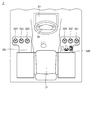
- FIG. 3 is a plan view showing the internal configuration of the cab 3 of the motor grader 100.
- the motor grader 100 mainly has a driver's seat 31, consoles 32R and 32L, a steering wheel 34, and a display device 37 in the cab 3.
- the driver's seat 31 is a seat for an operator who operates the motor grader 100 to sit on.
- Consoles 32R and 32L are arranged on the side of the driver's seat 31.
- An operation lever which is an operator operation device, is supported on the upper parts of the consoles 32R and 32L.
- the operation lever supported on the upper part of the consoles 32R and 32L mainly has at least an articulate operation lever 321 and a leaning operation lever 322, and a plurality of work machine operation levers 323.
- the steering wheel 34 is arranged in front of the driver's seat 31.
- the steering wheel 34 is for operating the steering mechanism and steering the front wheels 11 of the motor grader 100.
- the motor grader 100 can be turned by the operator rotating the steering wheel 34.
- a steering lever may be provided instead of the steering wheel to enable steering by operating the lever. Alternatively, it is also possible to provide both the steering wheel and the steering lever.
- the display device 37 displays various information.
- the display device 37 is, for example, a liquid crystal display device.
- the operator can determine the state of the motor grader 100 based on the information displayed on the display device 37.
- the main controller (FIG. 6) causes the display device 37 to display various types of information. An example of the information displayed on the display device 37 will be described later.
- the motor grader 100 can perform an articulating operation of rotating the front frame 22 with respect to the rear frame 21.
- the motor grader 100 includes a rotation mechanism for performing an articulating operation.
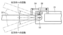
- FIG. 4 is a diagram illustrating an outline of the configuration of the rotating mechanism. As shown in FIG. 4, the front frame 22 and the rear frame 21 are connected by a connecting shaft 53.
- the connecting shaft 53 extends in the vertical direction (vertical to the paper surface in FIG. 4).
- the connecting shaft 53 is arranged substantially below the cab 3 (not shown in FIG. 4).
- the connecting shaft 53 connects the front frame 22 to the rear frame 21 so as to be rotatable with respect to the rear frame 21.
- the front frame 22 is rotatable in both directions with respect to the rear frame 21 around the connecting shaft 53.
- the angle formed by the front frame 22 with respect to the rear frame 21 can be adjusted.
- the rotation of the front frame 22 with respect to the rear frame 21 is performed by expanding and contracting the articulated cylinder 54 connected between the front frame 22 and the rear frame 21 by operating from the cab 3.
- An angle sensor 38 is attached to the rear frame 21, and detects an articulated angle, which is a rotation angle of the front frame 22 with respect to the rear frame 21.
- the turning radius of the motor grader 100 when turning can be made smaller, and grooving and method cutting work can be performed by offset running.
- the offset running means that the motor grader 100 is driven straight by making the direction in which the front frame 22 is rotated with respect to the rear frame 21 and the direction in which the front wheels 11 are rotated with respect to the front frame 22 are opposite to each other. Say that.
- the operator operates the articulate operation lever 321 to execute the articulate operation.
- the articulating operation is started.
- the articulating operation is stopped, and the motor grader 100 maintains the articulating angle when the articulating operating lever 321 is returned to the neutral position.
- the articulate operation lever 321 automatically returns to the neutral position.
- the articulate angle changes within a predetermined angle range.
- the motor grader 100 maintains the articulate angle at the time when the operation is stopped.
- the articulated cylinder 54 is an example of an actuator that rotates the front frame 22 with respect to the rear frame 21.
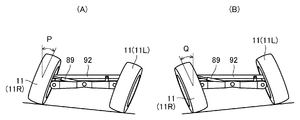
- FIG. 5 is a conceptual diagram illustrating the leaning operation of the motor grader 100.
- FIG. 5A shows the state of the front wheel 11 in the left leaning operation. The case where the front wheel 11 is inclined to the left by an angle P according to the expansion and contraction of the leaning cylinder 92 is shown.
- the motor grader 100 is turning left, for example, the turning radius at the time of turning left can be reduced by performing the leaning operation as shown in FIG. 5 (A).
- FIG. 5B shows the state of the front wheel 11 in the right leaning operation.
- the case where the front wheel 11 is tilted to the right by an angle Q according to the expansion and contraction of the leaning cylinder 92 is shown.
- the motor grader 100 is turning to the right, for example, the turning radius at the time of turning to the right can be reduced by performing the leaning operation as shown in FIG. 5 (B).
- the motor grader 100 can maintain straightness by performing a leaning operation during work.
- FIG. 6 is a functional block diagram illustrating the configuration of the control system of the motor grader 100.
- the relationship between the main controller 150 and other peripheral devices is shown.
- peripheral devices the work equipment operation lever 323, the articulate operation lever 321 and the display device 37, the switch 390, the engine 136, the engine controller 138, the transmission 146, the transmission controller 148, and the valve 134 are used.
- GNSS Global Navigation Satellite System
- the hydraulic actuator 140 includes, for example, lift cylinders 44 and 45, drawbar shift cylinder 46, blade shift cylinder 47, tilt cylinder 48, swivel motor 49, articulate cylinder 54, steering cylinder 80, leaning cylinder 92 and the like.
- the main controller 150 is a controller that controls the entire motor grader 100.
- the main controller 150 is composed of a CPU (Central Processing Unit) that executes a program, a non-volatile memory in which the program is stored, and the like.
- CPU Central Processing Unit
- the main controller 150 controls the engine controller 138, the transmission controller 148, the display device 37, the valve 134, and the like.
- the main controller 150, the engine controller 138, and the transmission controller 148 are described as having different configurations, but it is also possible to use one common controller. Further, the main controller 150 does not have to control the engine controller 138 and the transmission controller 148.
- the main controller 150 includes a work equipment operation lever 323, an articulate operation lever 321, a switch 390, a display device 37, a valve 134, a GNSS176, an angle sensor 38, and a sensor 171, 172, 173, 174. 175 is connected.
- the work equipment operation lever 323 outputs a lever operation signal (electric signal) according to the operation direction and / or the operation amount to the main controller 150.
- the articulated operation lever 321 outputs a lever operation signal (electrical signal) according to the operation direction and / or the operation amount to the main controller 150.
- the switch 390 is one of the operator operating devices.
- the switch 390 outputs an operation command signal to enable and / or disable the specific function to the main controller 150.
- GNSS176 detects the position of the motor grader 100.
- GNSS refers to a global navigation satellite system.
- GPS Global Positioning System
- the GNSS176 transmits the position information of the motor grader 100 to the main controller 150.
- the sensor 171 detects the rotation angle (blade propulsion angle) of the swivel circle 41.
- the sensor 171 transmits information on the rotation angle of the swivel circle 41 to the main controller 150.
- the sensor 172 detects the inclination of the blade 42.
- the sensor 172 is, for example, an IMU (Inertial Measurement Unit).
- the sensor 172 transmits the tilt information of the blade 42 to the main controller 150.
- the Sensor 173 detects the inclination of the vehicle body 2.
- the sensor 172 is, for example, an IMU (Inertial Measurement Unit).
- the sensor 173 transmits the inclination information of the vehicle body 2 to the main controller 150.
- the sensor 174 detects the position of the hydraulic actuator 140. Specifically, the sensor 174 detects the stroke length of the hydraulic actuator 140. The sensor 174 transmits the position information of the hydraulic actuator 140 to the main controller 150.
- the sensor 175 detects obstacles (including people) around the motor grader 100.
- the sensor 175 can detect an obstacle behind the cab 3.
- the sensor 175 is used for ambient monitoring.
- the sensor 175 transmits obstacle information to the main controller 150.
- the number of sensors 175 is not limited to one.
- the motor grader 100 may be equipped with a similar sensor so as to be able to detect not only the rear of the cab 3 but also multiple directions such as the left direction and the right direction of the cab 3.
- the main controller 150 includes an operation signal detection unit 151, a display control unit 153, a storage unit 155, and a valve control unit 156.
- the operation signal detection unit 151 detects the operation signal from the articulate operation lever 321.
- the operation signal detection unit 151 receives the operation command signal from the switch 390.
- the operation signal detection unit 151 outputs the received operation signal to the display control unit 153.
- the display control unit 153 controls the output of the display device 37.
- the display control unit 153 controls the screen display on the display device 37.
- the display control unit 153 displays various support information (work support information and driving support information) on the display device 37.
- the display control unit 153 displays various screens (see FIG. 9) described later on the display device 37.
- the storage unit 155 stores various programs executed by the CPU.
- the storage unit 155 stores, for example, information about an engine output torque curve.
- the valve control unit 156 receives the operation signals from the work equipment operation lever 323 and the articulate operation lever 321.
- the valve control unit 156 controls the drive of the hydraulic actuator 140 by controlling the valve 134 according to the magnitude of the current value which is the output operation command.
- the valve control unit 156 may correct the current value, which is an operation command to the valve 134, based on the information from the sensor 174.
- the valve 134 is an electromagnetic proportional valve.
- the valve 134 controls the amount of hydraulic oil supplied from the hydraulic pump (not shown) to the hydraulic actuator 140 according to the operation signal.
- the motor grader 100 displays the articulated state (rotation state of the front frame 22) on the display device 37.
- the motor grader 100 does not display the articulated state on the display device 37 when a specific function is enabled in the motor grader 100.
- the details of the articulated state will be described later (FIG. 9). An example of a specific function will be described below.
- the specific function includes a function of executing automatic control and a function of detecting obstacles around the motor grader 100 by the sensor 175.
- Examples of the function of executing the automatic control include the automatic control of the working machine and the automatic control of the running.
- Examples of automatic control of work equipment include cross slope control and machine control.
- Machine control is to acquire the position of the blade in real time using information from the total station (TS), GNSS176 and sensor 174, and control the blade (earth removal plate) based on the difference from the data for computerized construction. That is.
- the cross slope control will be described later.
- automatic driving control examples include automatic steering control, automatic braking operation, auto cruise control, leaning automatic control, and the like.
- the automatic steering control is to control a steering device (system) for changing the traveling direction of the motor grader 100.
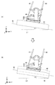
- FIG. 7 is a diagram for explaining an outline of cross slope control.
- the cross slope control is a technique for automatically controlling the blade 42 so that the cross slope of the ground to be leveled becomes the target cross slope set by the operator.
- the slope of the blade 42 is automatically controlled.
- the cross slope control is realized based on the instruction from the main controller 150.
- the main controller 150 receives the propulsion angle information of the blade 42, the inclination information of the blade 42, and the inclination information of the vehicle body 2 from the sensors 171 to 173, and the inclination of the blade 42 is a target cross slope set by the operator.
- the blade 42 is controlled so as to be.
- the target cross slope set by the operator is temporarily stored in the storage unit 155.
- the ground leveling M is leveled by the blade 42 so as to have a target cross slope ⁇ (gradient with respect to the horizontal plane L1) set by the operator.
- FIG. 7A when the operator starts an operation of changing the stroke length of one of the lift cylinders 44 and 45 designated in advance by the operator (hereinafter, also referred to as “lift cylinder on the manual control side”). , The motor grader 100 automatically changes the stroke length of the other lift cylinder (hereinafter, also referred to as “lift cylinder on the automatic control side”) so as to maintain the target cross slope ⁇ .
- the operator increases the stroke length of the lift cylinder 44 (of the blade 42) as shown in FIG. 7 (B).
- the motor grader 100 automatically increases the stroke length of the lift cylinder 45 so as to maintain the target cross slope ⁇ .
- Cross slope control is effective even when the operator changes the blade propulsion angle. Even if the blade propulsion angle is changed, the motor grader 100 maintains a preset target cross slope ⁇ .
- the main controller 150 causes the display device 37 to display the articulated state.
- the main controller 150 does not display the articulated status on the display device 37 when the above-mentioned specific function is effective in the motor grader 100.
- the main controller 150 receives a command to operate the articulated cylinder 54 in a state where the articulated state is not displayed on the display device 37 due to the above-mentioned specific function being enabled, the main controller 150 displays the articulated state. Display on 37.
- the main controller 150 does not display the articulated state on the display device 37 when the above-mentioned specific function is effective when the operation of the articulated cylinder 54 is stopped.
- the articulate operation lever 321 Upon receiving the operation, the articulate operation lever 321 transmits a command to operate the articulate cylinder 54 to the main controller 150.
- FIG. 8 is a diagram for explaining the state transition of the screen displayed on the display device 37.
- the display control unit 153 of the main controller 150 first displays the normal screen G1 on the display device 37 (state # 1).
- the normal screen G1 includes an articulated status display.
- the display control unit 153 When the condition a is satisfied in the state # 1, the display control unit 153 causes the display device 37 to display the dedicated screen G2 of the specific function (state # 2). In this way, the display control unit 153 shifts the screen state from the state # 1 to the state # 2.
- the dedicated screen G2 does not include the articulated status display.
- the main controller 150 determines whether or not the predetermined condition b is satisfied in the state (state # 2) in which the dedicated screen G2 is displayed on the display device 37.
- Condition b is that the main controller 150 has received a command to invalidate the specific function.
- the display control unit 153 When the condition b is satisfied in the state # 2, the display control unit 153 causes the display device 37 to display the normal screen G1 (state # 1). In this way, the display control unit 153 shifts the screen state from the state # 2 to the state # 1.
- Condition c is that the articulate operating lever 321 has moved to a position other than the neutral position. Specifically, the condition c is that the main controller 150 has received the operation signal from the articulate operation lever 321. The condition c is that the main controller 150 has received a command to operate the articulated cylinder 54.
- the display control unit 153 causes the display device 37 to display the screen G3 including the image 375 (see FIG. 9) showing the articulated state (state # 3). In this way, the display control unit 153 shifts the screen state from the state # 2 to the state # 3.
- the main controller 150 determines whether or not the predetermined condition d is satisfied in the state where the screen G3 is displayed on the display device 37 (state # 3).
- the condition d is that the main controller 150 has not received the command to invalidate the specific function, and the articulating operation lever 321 has returned to the neutral position.
- the condition d is that the specific function is effective and the main controller 150 determines that the operation of the articulating cylinder 54 is stopped.
- the display control unit 153 When the condition d is satisfied in the state # 3, the display control unit 153 causes the display device 37 to display the dedicated screen G2 (state # 2). In this way, the display control unit 153 shifts the screen state from the state # 3 to the state # 2.
- the main controller 150 determines whether or not the above-mentioned condition b is satisfied in the state (state # 3) in which the screen G3 is displayed on the display device 37.
- the display control unit 153 causes the display device 37 to display the normal screen G1 (state # 1). In this way, the display control unit 153 shifts the screen state from the state # 3 to the state # 1.
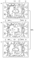
- FIG. 9 is a schematic view of a screen displayed by the display device 37. As shown in FIG. 9, the screen displayed on the display device 37 transitions based on the above-mentioned conditions a to d.
- FIG. 9A corresponds to state # 1 of FIG.
- FIG. 9B corresponds to state # 2 of FIG.
- FIG. 9C corresponds to state # 3 of FIG.
- the normal screen G1 includes at least an image 375 showing an articulated state.
- Image 375 represents an articulated angle.
- Image 375 includes pointer 3751.
- the pointer 3751 tilts to the right according to the articulating angle.
- the pointer 3751 is tilted to the left according to the articulation angle. The operator can determine the current articulated state (articulated angle) from the position pointed to by the pointer 3751.
- a dedicated screen G2 for cross slope control is displayed on the display device 37 as shown in FIG. 9B.
- the dedicated screen G2 displays an image related to cross slope control in the center of the screen instead of the image 375 showing the articulated state.
- the display control unit 153 has an image showing the measured cross slope (%), an image showing the target cross slope (%), and an image showing the state of the target cross slope (blade and horizontal plane) in the center of the screen. The image) and is mainly displayed.
- a screen G3 including an image 375 showing an articulated state is displayed on the display device 37 instead of the dedicated screen G2. NS.
- a dedicated screen G2 is displayed on the display device 37 instead of the screen G3 as shown in FIG. 9B.
- the normal screen G1 is displayed on the display device 37 instead of the screen G3 as shown in FIG. 9A.
- the motor grader 100 enables the cross slope control so that the operator can start the articulation even if the display device 37 does not display the articulation status.
- the operating lever 321 is moved from the neutral position, the articulated state is displayed on the display device 37 as shown in FIG. 9C.
- the articulated state (change state) is displayed on the display device 37.
- the articulated state can be displayed on the display device at a timing suitable for the operator.
- the operating device for operating the articulated cylinder 54 is not limited to the articulated operating lever 321.
- the operating device for operating the articulated cylinder 54 may be a momentary switch.
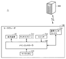
- FIG. 10 is a diagram for explaining another device configuration for operating the articulated cylinder 54.
- the system 1 includes a motor grader 100 and a server 900.
- the motor grader 100 can communicate with the server 900.
- the motor grader 100 includes at least a main controller 150, a display device 37, a touch screen 711, a switch 712, a microphone 713, and a communication interface 715.
- the main controller 150 communicates with the server 900 via the communication interface 715.
- the touch screen includes a display and a touch panel.
- the motor grader 100 may be configured such that commands for operating the articulated cylinder 54 are transmitted from these devices to the main controller 150 by operating either the touch screen 711 or the switch 712.
- the motor grader 100 may be configured so that commands for operating the articulated cylinder 54 are transmitted from these devices to the main controller 150 based on voice input via the microphone 713.
- the motor grader 100 may be configured so that the main controller 150 receives a command to operate the articulating cylinder 54 from the server 900 via the communication interface 715.
Landscapes
- Engineering & Computer Science (AREA)
- Mining & Mineral Resources (AREA)
- Civil Engineering (AREA)
- General Engineering & Computer Science (AREA)
- Structural Engineering (AREA)
- Mechanical Engineering (AREA)
- Component Parts Of Construction Machinery (AREA)
- Operation Control Of Excavators (AREA)
Abstract
モータグレーダは、フロントフレームと、リアフレームと、フロントフレームをリアフレームに対して回動させるアクチュエータと、オペレータ操作装置と、表示装置と、コントローラとを備える。コントローラは、オペレータ操作装置からの信号に基づいて、回動の状態を示す画像、または、回動の状態を示す画像とは異なる画像のいずれか一方を表示装置に表示させる。
Description
本開示は、モータグレーダおよびモータグレーダの表示制御方法に関する。
従来、アーティキュレート式のモータグレーダが知られている。
たとえば国際公開第2015/088048号(特許文献1)に開示されたモータグレーダは、アーティキュレートの状態を運転室の表示装置に表示することができる。モータグレーダのオペレータは、この表示を観察しながら、モータグレーダの操作を行う。
たとえば国際公開第2015/088048号(特許文献1)に開示されたモータグレーダは、アーティキュレートの状態を運転室の表示装置に表示することができる。モータグレーダのオペレータは、この表示を観察しながら、モータグレーダの操作を行う。
また、モータグレーダやブルドーザ等の作業機械において、自動制御等の特定の機能を実行している際に、当該機能の状態を表示する技術が知られている。
たとえば、特開昭58-173230号公報(特許文献2)では、モータグレーダが横断勾配制御を実行している際に、仕上げ傾斜角を表示する。
ところで、モータグレーダは、整地作業等を行うために、地面近傍にブレードを備えている。運転室内のオペレータは、ブレードを直視しながら作業を行う必要があるため、モータグレーダは、前下方の視界を十分に確保できる構造としなければならない。
このため、モータグレーダの表示装置の表示領域の大きさは、なるべく小さくするのが好ましい。
一方で、モータグレーダが特定の機能を実行している際に当該機能の状態を表示装置に表示する場合、表示装置の表示領域の大きさの関係により、アーティキュレートの状態を表示装置に表示できない場合がある。
このような場合、上記機能を実行中にオペレータがアーティキュレートの状態を変更する操作を行っても、アーティキュレートの状態がどのようになっているのかを表示装置にて視認できない。
本開示は、オペレータにとって好適なタイミングでアーティキュレートの状態を表示装置に表示可能とするモータグレーダを提供することにある。
本開示のある局面に従うと、モータグレーダは、フロントフレームと、リアフレームと、フロントフレームをリアフレームに対して回動させるアクチュエータと、オペレータ操作装置と、表示装置と、コントローラとを備える。コントローラは、オペレータ操作装置からの信号に基づいて、回動の状態を示す画像、または、回動の状態を示す画像とは異なる画像のいずれか一方を表示装置に表示させる。
本開示の他の局面に従うと、モータグレーダは、フロントフレームと、リアフレームと、フロントフレームをリアフレームに対して回動させるアクチュエータと、表示装置と、回動の状態を示す画像を表示装置に表示させるコントローラとを備える。コントローラは、モータグレーダにおいて特定の機能が有効であるときには、回動の状態を示す画像を表示装置に表示させない。コントローラは、特定の機能が有効であることにより回動の状態を示す画像が表示装置に表示されていない状態において、アクチュエータを動作させる指令を受信すると、回動の状態を示す画像を表示装置に表示させる。
本開示のさらに他の局面に従うと、コントローラを備えるモータグレーダの表示制御方法は、モータグレーダのアーティキュレートの状態を示す画像を表示装置に表示させるステップと、オペレータ操作装置からの信号を受信するステップと、受信した信号に基づいて、アーティキュレートの状態を示す画像、または、アーティキュレートの状態を示す画像とは異なる画像のいずれか一方を表示装置に表示させるステップとを備える。
本開示のさらに他の局面に従うと、コントローラを備えるモータグレーダの表示制御方法は、モータグレーダのアーティキュレートの状態を示す画像を表示装置に表示させるステップと、モータグレーダにおいて特定の機能が有効であるときには、アーティキュレートの状態を示す画像を表示装置に表示させることを無効にするステップと、特定の機能が有効であることによりアーティキュレートの状態を示す画像が表示装置に表示されていない状態のときに、アーティキュレートを行うためのアクチュエータを動作させる指令を受信するステップと、指令を受信したことに基づき、アーティキュレートの状態を示す画像を表示装置に表示させるステップとを備える。
本開示によれば、オペレータにとって好適なタイミングでアーティキュレートの状態を表示装置に表示可能となる。
以下、実施形態について図に基づいて説明する。なお、以下の説明では、同一部品には、同一の符号を付している。それらの名称および機能も同じである。したがって、それらについての詳細な説明は繰り返さない。
<A.概略構成>
図1は、実施形態に基づくアーティキュレート式のモータグレーダ100の構成を概略的に示す斜視図である。図2は、図1に示されるモータグレーダ100の平面図である。
図1は、実施形態に基づくアーティキュレート式のモータグレーダ100の構成を概略的に示す斜視図である。図2は、図1に示されるモータグレーダ100の平面図である。
図1および図2に示されるように、実施形態に基づくモータグレーダ100は、車体2と、作業機4とで構成される。車体2は、走行輪である前輪11と、走行輪である後輪12と、リアフレーム21と、フロントフレーム22と、キャブ3とを主に備えている。前輪11は、左右の片側において一輪ずつを有し、右前輪11Rと、左前輪11Lとを含んでいる。図においては、片側一輪ずつの2つの前輪11と片側二輪ずつの4つの後輪12とからなる走行輪が示されているが、前輪および後輪の数および配置はこれに限られない。
モータグレーダ100は、エンジン室6に配置されたエンジン等の構成部品を備えている。作業機4は、ブレード42を含む。モータグレーダ100は、ブレード42で整地作業、除雪作業、軽切削、材料混合等の作業を行なうことができる。
以下の図の説明において、モータグレーダ100が直進走行する方向を、モータグレーダ100の前後方向という。モータグレーダ100の前後方向において、作業機4に対して前輪11が配置されている側を、前方向とする。モータグレーダ100の前後方向において、作業機4に対して後輪12が配置されている側を、後方向とする。モータグレーダ100の左右方向、または側方とは、平面視において前後方向と直交する方向である。前方向を見て左右方向の右側、左側が、それぞれ右方向、左方向である。モータグレーダ100の上下方向とは、前後方向および左右方向によって定められる平面に直交する方向である。上下方向において地面のある側が下側、空のある側が上側である。
以下の図においては、前後方向を図中矢印X、左右方向を図中矢印Y、上下方向を図中矢印Zで示している。
リアフレーム21は、フロントフレーム22の後方に配置されている。リアフレーム21は、外装カバー25と、エンジン室6に配置されたエンジン等の構成部品とを支持している。外装カバー25はエンジン室6を覆っている。リアフレーム21には、上記のたとえば片側二輪ずつの後輪12の各々がエンジンからの駆動力によって回転駆動可能に取り付けられている。
キャブ3は、リアフレーム21に搭載されている。キャブ3は、オペレータが搭乗するための室内空間を有しており、リアフレーム21の前端に配置されている。なお、キャブ3は、フロントフレーム22に搭載されていてもよい。
キャブ3の内部には、前輪11を操舵するためのステアリングホイール、変速レバー、作業機4の操作レバー、ブレーキペダル、アクセルペダル等のオペレータ操作装置が設けられている。
フロントフレーム22は、リアフレーム21の前方に取り付けられている。フロントフレーム22の前端部には、上記のたとえば片側一輪ずつの前輪11が回転可能に取り付けられている。前輪11は、ステアリングシリンダ80の伸縮によって操舵可能に取り付けられている。前輪11は、リーニングシリンダ92(図5参照)の伸縮によって左右方向に傾斜可能に取り付けられている。また、フロントフレーム22の前端部には、カウンターウェイト51が取り付けられている。
作業機4は、ドローバ40と、旋回サークル41と、ブレード42と、油圧式の旋回モータ49と、各種のシリンダ44~48とを主に有している。
ドローバ40の前端部は、フロントフレーム22の先端部に揺動可能に取り付けられている。ドローバ40の後端部は、一対のリフトシリンダ44,45によってフロントフレーム22に支持されている。この一対のリフトシリンダ44,45の同期した伸縮によって、ドローバ40の後端部がフロントフレーム22に対して上下に昇降可能である。またドローバ40は、リフトシリンダ44,45の異なった伸縮によって、車両進行方向に沿った軸を中心に上下に揺動可能である。
フロントフレーム22とドローバ40の一方の側端部とには、ドローバシフトシリンダ46が取り付けられている。このドローバシフトシリンダ46の伸縮によって、ドローバ40は、フロントフレーム22に対して左右に移動可能である。
旋回サークル41は、ドローバ40の後端部に旋回可能に支持されている。旋回サークル41は、旋回モータ49によって、ドローバ40に対し車両上方から見て時計方向または反時計方向に旋回駆動可能である。旋回サークル41の旋回駆動によって、平面視におけるフロントフレーム22に対するブレード42の傾斜角度(以下、「ブレード推進角」とも称する)が調整される。なお図2に示される作業機4では、旋回サークル41は、図1に示される配置と比較して、平面視において反時計回り方向に旋回した位置にある。したがって図2に示されるブレード42は、図1に示されるブレード42とは、異なる位置に配置されている。
ブレード42は、旋回サークル41に支持されている。ブレード42は、旋回サークル41およびドローバ40を介して、フロントフレーム22に支持されている。
ブレードシフトシリンダ47は、旋回サークル41およびブレード42に取り付けられており、ブレード42の長手方向に沿って配置されている。ブレードシフトシリンダ47によって、ブレード42は旋回サークル41に対して左右方向に移動可能である。
チルトシリンダ48は、旋回サークル41およびブレード42に取り付けられている。チルトシリンダ48を伸縮させることによって、ブレード42は旋回サークル41に対してブレード42の長手方向に延びる軸を中心に揺動して、上下方向に向きを変更することができる。
以上のように、ブレード42は、ドローバ40と旋回サークル41とを介して、車両に対する上下の昇降、車両進行方向に沿った軸を中心とする揺動、左右方向の移動、および、ブレード42の長手方向に延びる軸を中心とする揺動を行なうことが可能である。
<B.キャブ>
図3は、モータグレーダ100のキャブ3の内部の構成を示す平面図である。
図3は、モータグレーダ100のキャブ3の内部の構成を示す平面図である。
図3に示されるように、モータグレーダ100は、キャブ3内に、運転席31、コンソール32R,32Lと、ステアリングホイール34、表示装置37とを主に有している。
運転席31は、モータグレーダ100を操作するオペレータが着座するためのシートである。運転席31の側方には、コンソール32R,32Lが配置されている。
コンソール32R,32Lの上部には、オペレータ操作装置である操作レバーが支持されている。
コンソール32R,32Lの上部に支持された操作レバーは、少なくともアーティキュレート操作レバー321と、リーニング操作レバー322と、複数の作業機操作レバー323とを主に有している。
ステアリングホイール34は、運転席31の前方に配置されている。ステアリングホイール34は、ステアリング機構を操作し、モータグレーダ100の前輪11を操舵するためのものである。オペレータがステアリングホイール34を回転操作することにより、モータグレーダ100は旋回することが可能である。ステアリングホイールの代わりにステアリングレバーを設けて、レバー操作により操舵を可能としてもよい。または、ステアリングホイールとステアリングレバーとの両方を設ける構成とすることも可能である。
表示装置37は、各種の情報を表示する。表示装置37は、たとえば、液晶ディスプレイ装置である。オペレータは、表示装置37に表示された情報に基づき、モータグレーダ100の状態を判断できる。メインコントローラ(図6)が表示装置37に各種の情報を表示させる。表示装置37に表示される情報の例については、後述する。
<C.アーティキュレート>
モータグレーダ100は、リアフレーム21に対してフロントフレーム22を回動させるアーティキュレート動作が可能である。モータグレーダ100は、アーティキュレート動作を行なうための回動機構を備えている。
モータグレーダ100は、リアフレーム21に対してフロントフレーム22を回動させるアーティキュレート動作が可能である。モータグレーダ100は、アーティキュレート動作を行なうための回動機構を備えている。
図4は、回動機構の構成の概略について説明する図である。
図4に示されるように、フロントフレーム22と、リアフレーム21とは、連結軸53により連結されている。連結軸53は、上下方向(図4においては紙面垂直方向)に延びている。連結軸53は、キャブ3(図4には不図示)のほぼ下方位置に配置されている。
図4に示されるように、フロントフレーム22と、リアフレーム21とは、連結軸53により連結されている。連結軸53は、上下方向(図4においては紙面垂直方向)に延びている。連結軸53は、キャブ3(図4には不図示)のほぼ下方位置に配置されている。
連結軸53は、フロントフレーム22を、リアフレーム21に対して回動可能に、リアフレーム21に連結している。フロントフレーム22は、連結軸53を中心として、リアフレーム21に対して両方向に旋回可能である。リアフレーム21に対してフロントフレーム22がなす角度が調整可能とされている。
リアフレーム21に対するフロントフレーム22の回動は、キャブ3からの操作により、フロントフレーム22とリアフレーム21との間に連結されたアーティキュレートシリンダ54を伸縮させることで行なわれる。リアフレーム21には角度センサ38が取り付けられており、リアフレーム21に対するフロントフレーム22の回動角度であるアーティキュレート角度を検出する。
フロントフレーム22をリアフレーム21に対して回動させる(アーティキュレートさせる)ことで、モータグレーダ100の旋回時の旋回半径をより小さくすること、および、オフセット走行による溝掘や法切作業が可能である。オフセット走行とは、フロントフレーム22をリアフレーム21に対して回動させる方向と、前輪11をフロントフレーム22に対して旋回させる方向とをそれぞれ逆方向とすることにより、モータグレーダ100を直進走行させることをいう。
オペレータが、アーティキュレート操作レバー321を操作することにより、アーティキュレート動作が実行される。オペレータがアーティキュレート操作レバー321を中立位置から前方向または後ろ方向に倒すことにより、アーティキュレート動作が開始する。オペレータがアーティキュレート操作レバー321を中立位置に復帰させると、アーティキュレート動作が停止し、かつ、モータグレーダ100は、アーティキュレート操作レバー321を中立位置に復帰させたときのアーティキュレート角度を維持する。なお、オペレータがアーティキュレート操作レバー321から手を離すと、アーティキュレート操作レバー321は自動的に中立位置に復帰する。
このように、オペレータがアーティキュレート操作レバー321を操作している間、アーティキュレート角度は予め定められた角度範囲内で変化する。オペレータがアーティキュレート操作レバー321の操作を停止すると、モータグレーダ100は、操作を停止した時点におけるアーティキュレート角度を維持する。
なお、アーティキュレートシリンダ54は、フロントフレーム22をリアフレーム21に対して回動させるアクチュエータの例である。
図5は、モータグレーダ100のリーニング動作を説明する概念図である。
図5(A)には、左リーニング動作の前輪11の状態が示されている。リーニングシリンダ92の伸縮に従って前輪11が左方向に角度Pだけ傾斜している場合が示されている。モータグレーダ100は、たとえば左旋回をしている場合において、図5(A)に示すようにリーニング動作を行うことにより、左旋回時の旋回半径を小さくすることができる。
図5(A)には、左リーニング動作の前輪11の状態が示されている。リーニングシリンダ92の伸縮に従って前輪11が左方向に角度Pだけ傾斜している場合が示されている。モータグレーダ100は、たとえば左旋回をしている場合において、図5(A)に示すようにリーニング動作を行うことにより、左旋回時の旋回半径を小さくすることができる。
図5(B)には、右リーニング動作の前輪11の状態が示されている。リーニングシリンダ92の伸縮に従って前輪11が右方向に角度Qだけ傾斜している場合が示されている。モータグレーダ100は、たとえば右旋回をしている場合において、図5(B)に示すようにリーニング動作を行うことにより、右旋回時の旋回半径を小さくすることができる。
また、モータグレーダ100は、作業時にリーニング動作を行うことにより直進性を維持することができる。
<E.システム構成>
図6は、モータグレーダ100の制御システムの構成を説明する機能ブロック図である。
図6は、モータグレーダ100の制御システムの構成を説明する機能ブロック図である。
図6に示すように、メインコントローラ150と、他の周辺機器との関係が示されている。ここでは、周辺機器として、作業機操作レバー323と、アーティキュレート操作レバー321と、表示装置37と、スイッチ390と、エンジン136と、エンジンコントローラ138と、トランスミッション146と、トランスミッションコントローラ148と、バルブ134と、GNSS(Global Navigation Satellite System)176と、角度センサ38と、センサ171,172,173,174,175と、油圧アクチュエータ140とが示されている。油圧アクチュエータ140は、たとえば、リフトシリンダ44,45、ドローバシフトシリンダ46、ブレードシフトシリンダ47、チルトシリンダ48、旋回モータ49、アーティキュレートシリンダ54、ステアリングシリンダ80、リーニングシリンダ92等である。
メインコントローラ150は、モータグレーダ100全体を制御するコントローラである。メインコントローラ150は、プログラムを実行するCPU(Central Processing Unit)、プログラムが格納された不揮発性メモリ等により構成される。
メインコントローラ150は、エンジンコントローラ138、トランスミッションコントローラ148、表示装置37、バルブ134等を制御する。なお、本例においては、メインコントローラ150と、エンジンコントローラ138と、トランスミッションコントローラ148とがそれぞれ別々の構成について説明しているが共通の1つのコントローラとすることも可能である。また、メインコントローラ150は、エンジンコントローラ138とトランスミッションコントローラ148を制御しなくてもよい。
メインコントローラ150には、作業機操作レバー323と、アーティキュレート操作レバー321と、スイッチ390と、表示装置37と、バルブ134と、GNSS176と、角度センサ38と、センサ171,172,173,174,175とが接続される。
作業機操作レバー323は、操作方向および/または操作量に応じたレバー操作信号(電気信号)をメインコントローラ150に出力する。アーティキュレート操作レバー321は、操作方向および/または操作量に応じたレバー操作信号(電気信号)をメインコントローラ150に出力する。
スイッチ390は、オペレータ操作装置の一つである。スイッチ390は、特定機能を有効および/または無効する操作指令信号をメインコントローラ150に出力する。
GNSS176は、モータグレーダ100の位置を検出する。GNSSとは、全地球航法衛星システムをいう。全地球航法衛星システムの一例として、GPS(Global Positioning System)が挙げられる。GNSS176は、モータグレーダ100の位置情報をメインコントローラ150に送信する。
センサ171は、旋回サークル41の回転角(ブレード推進角)を検出する。センサ171は、旋回サークル41の回転角の情報をメインコントローラ150に送信する。
センサ172は、ブレード42の傾斜を検出する。センサ172は、たとえば、IMU(Inertial Measurement Unit)である。センサ172は、ブレード42の傾斜情報を、メインコントローラ150に送信する。
センサ173は、車体2の傾斜を検出する。センサ172は、たとえば、IMU(Inertial Measurement Unit)である。センサ173は、車体2の傾斜情報をメインコントローラ150に送信する。
センサ174は、油圧アクチュエータ140の位置を検出する。具体的には、センサ174は、油圧アクチュエータ140のストローク長を検出する。センサ174は、油圧アクチュエータ140の位置情報をメインコントローラ150に送信する。
センサ175は、モータグレーダ100の周囲の障害物(人を含む)を検知する。センサ175は、キャブ3の後方の障害物を検知することができる。センサ175は、周囲監視のために用いられる。センサ175は、障害物の情報をメインコントローラ150に送信する。なお、センサ175の数は1つに限定されるものではない。また、モータグレーダ100は、キャブ3の後方のみならず、キャブ3の左方向および右方向等の多方向を検出可能なように、同様のセンサを搭載してもよい。
メインコントローラ150は、操作信号検出部151と、表示制御部153と、記憶部155と、バルブ制御部156とを含む。
操作信号検出部151は、アーティキュレート操作レバー321からの操作信号を検出する。操作信号検出部151は、スイッチ390からの操作指令信号を受信する。操作信号検出部151は、受信した操作信号を表示制御部153に出力する。
表示制御部153は、表示装置37の出力を制御する。表示制御部153は、表示装置37における画面表示を制御する。表示制御部153は、各種の支援情報(作業支援情報および運転支援情報)を表示装置37に表示する。表示制御部153は、表示装置37に後述する各種の画面(図9参照)を表示する。
記憶部155は、CPUによって実行される各種のプログラムを格納している。記憶部155は、たとえばエンジン出力トルクカーブに関する情報を格納する。
バルブ制御部156は、作業機操作レバー323と、アーティキュレート操作レバー321とからの操作信号を受信する。バルブ制御部156は、出力する動作指令である電流値の大きさに応じてバルブ134を制御することにより、油圧アクチュエータ140の駆動を制御する。なお、バルブ制御部156は、センサ174からの情報に基づいて、バルブ134への動作指令である電流値を補正してもよい。バルブ134は、電磁比例弁である。バルブ134は、当該操作信号に従って油圧ポンプ(図示せず)から油圧アクチュエータ140へ供給される作動油の量を制御する。
<D.特定の機能>
モータグレーダ100は、デフォルトのモード(通常状態)では、アーティキュレートの状態(フロントフレーム22の回動の状態)を表示装置37に表示する。モータグレーダ100は、モータグレーダ100において特定の機能が有効であるときには、アーティキュレートの状態を表示装置37に表示しない。なお、アーティキュレートの状態の詳細については、後述する(図9)。以下、特定の機能の例について説明する。
モータグレーダ100は、デフォルトのモード(通常状態)では、アーティキュレートの状態(フロントフレーム22の回動の状態)を表示装置37に表示する。モータグレーダ100は、モータグレーダ100において特定の機能が有効であるときには、アーティキュレートの状態を表示装置37に表示しない。なお、アーティキュレートの状態の詳細については、後述する(図9)。以下、特定の機能の例について説明する。
特定の機能は、自動制御を実行する機能と、センサ175によってモータグレーダ100の周囲の障害物の検知を行う機能とを含む。自動制御を実行する機能の例としては、作業機の自動制御と、走行の自動制御とが挙げられる。
作業機の自動制御の例としては、横断勾配制御や、マシンコントロール等が挙げられる。マシンコントロールとは、トータルステーション(TS)、GNSS176およびセンサ174からの情報等を用いてブレードの位置をリアルタイムに取得し、情報化施工用データとの差分に基づき、ブレード(排土板)を制御することである。横断勾配制御については、後述する。
走行の自動制御の例としては、自動操舵制御、自動ブレーキ操作、オートクルーズ制御、リーニング自動制御等が挙げられる。なお、自動操舵制御とは、モータグレーダ100の進行方向を変えるための操舵装置(システム)を制御することである。
以下では、作業機の自動制御の例として、横断勾配制御の概要を説明する。
図7は、横断勾配制御の概要を説明するための図である。横断勾配制御とは、整地対象となる地面の横断勾配がオペレータによって設定された目標横断勾配となるように、ブレード42を自動制御する技術である。横断勾配制御では、ブレード42の傾斜が自動制御される。なお、横断勾配制御は、メインコントローラ150からの指示に基づき実現される。メインコントローラ150は、センサ171~173から、ブレード42の推進角情報と、ブレード42の傾斜情報と、車体2の傾斜情報とを受信し、ブレード42の傾斜がオペレータによって設定された目標横断勾配となるようにブレード42を制御する。オペレータによって設定された目標横断勾配は、一時的に記憶部155に記憶される。
図7は、横断勾配制御の概要を説明するための図である。横断勾配制御とは、整地対象となる地面の横断勾配がオペレータによって設定された目標横断勾配となるように、ブレード42を自動制御する技術である。横断勾配制御では、ブレード42の傾斜が自動制御される。なお、横断勾配制御は、メインコントローラ150からの指示に基づき実現される。メインコントローラ150は、センサ171~173から、ブレード42の推進角情報と、ブレード42の傾斜情報と、車体2の傾斜情報とを受信し、ブレード42の傾斜がオペレータによって設定された目標横断勾配となるようにブレード42を制御する。オペレータによって設定された目標横断勾配は、一時的に記憶部155に記憶される。
図7(A)では、整地面Mがオペレータによって設定された目標横断勾配θ(水平面L1に対する勾配)となるように、ブレード42によって整地されている。
図7(A)において、オペレータが、リフトシリンダ44、45のうちオペレータが予め指定した一方のリフトシリンダ(以下、「手動制御側のリフトシリンダ」とも称する)のストローク長を変更する操作を開始すると、モータグレーダ100は、目標横断勾配θを維持するように、他方のリフトシリンダ(以下、「自動制御側のリフトシリンダ」とも称する)のストローク長を自動で変更する。
具体的には、オペレータによってリフトシリンダ44が手動制御側のリフトシリンダとして設定された場合、図7(B)に示すように、オペレータが、リフトシリンダ44のストローク長を長くする操作(ブレード42の左側端部を下げる操作)を開始すると、モータグレーダ100は、目標横断勾配θを維持するようにリフトシリンダ45のストローク長を自動的に長くする。
横断勾配制御は、オペレータがブレード推進角を変更した場合であっても有効である。ブレード推進角を変更しても、モータグレーダ100は、予め設定された目標横断勾配θを維持する。
<F.画面表示の状態遷移>
以下では、表示装置37における画面遷移について説明する。まず、画面遷移の概要について説明する。その後、状態遷移図に基づき、画面遷移の詳細を説明する。さらに、画面遷移の具体例を説明する。
以下では、表示装置37における画面遷移について説明する。まず、画面遷移の概要について説明する。その後、状態遷移図に基づき、画面遷移の詳細を説明する。さらに、画面遷移の具体例を説明する。
(f1.画面遷移の概要)
メインコントローラ150は、アーティキュレートの状態を表示装置37に表示させる。メインコントローラ150は、モータグレーダ100において上述した特定の機能が有効であるときには、アーティキュレートの状態を表示装置37に表示させない。メインコントローラ150は、上記特定の機能が有効であることによりアーティキュレートの状態が表示装置37に表示されていない状態において、アーティキュレートシリンダ54を動作させる指令を受信すると、アーティキュレートの状態を表示装置37に表示させる。
メインコントローラ150は、アーティキュレートの状態を表示装置37に表示させる。メインコントローラ150は、モータグレーダ100において上述した特定の機能が有効であるときには、アーティキュレートの状態を表示装置37に表示させない。メインコントローラ150は、上記特定の機能が有効であることによりアーティキュレートの状態が表示装置37に表示されていない状態において、アーティキュレートシリンダ54を動作させる指令を受信すると、アーティキュレートの状態を表示装置37に表示させる。
メインコントローラ150は、アーティキュレートシリンダ54の動作が停止した際に上記特定の機能が有効であるときには、アーティキュレートの状態を表示装置37に表示させない。アーティキュレート操作レバー321は、操作を受け付けると、メインコントローラ150にアーティキュレートシリンダ54を動作させる指令を送信する。
(f2.画面遷移の詳細)
図8は、表示装置37に表示される画面の状態遷移を説明するための図である。
図8は、表示装置37に表示される画面の状態遷移を説明するための図である。
図8に示すように、メインコントローラ150の表示制御部153は、まず、通常画面G1を表示装置37に表示させる(状態#1)。通常画面G1は、アーティキュレートの状態表示を含む。
(1)状態#1と状態#2との間の遷移
メインコントローラ150は、通常画面G1が表示装置37に表示されている状態(状態#1)において予め定められた条件aが成立したか否かを判定する。条件aは、メインコントローラ150が特定機能を有効にする指令を受信したことである。
メインコントローラ150は、通常画面G1が表示装置37に表示されている状態(状態#1)において予め定められた条件aが成立したか否かを判定する。条件aは、メインコントローラ150が特定機能を有効にする指令を受信したことである。
表示制御部153は、状態#1において条件aが成立した場合、表示装置37に特定機能の専用画面G2を表示させる(状態#2)。このように、表示制御部153は、画面状態を状態#1から状態#2に遷移させる。専用画面G2は、アーティキュレートの状態表示を含まない。
メインコントローラ150は、専用画面G2が表示装置37に表示されている状態(状態#2)において予め定められた条件bが成立したか否かを判定する。条件bは、メインコントローラ150が特定機能を無効にする指令を受信したことである。
表示制御部153は、状態#2において条件bが成立した場合、表示装置37に通常画面G1を表示させる(状態#1)。このように、表示制御部153は、画面状態を状態#2から状態#1に遷移させる。
(2)状態#2と状態#3との間の遷移
メインコントローラ150は、専用画面G2が表示装置37に表示されている状態(状態#2)において予め定められた条件cが成立したか否かを判定する。条件cは、アーティキュレート操作レバー321が中立位置以外に移動したことである。詳しくは、条件cは、メインコントローラ150が、アーティキュレート操作レバー321からの操作信号を受信したことである。条件cは、メインコントローラ150が、アーティキュレートシリンダ54を動作させる指令を受信したことである。
メインコントローラ150は、専用画面G2が表示装置37に表示されている状態(状態#2)において予め定められた条件cが成立したか否かを判定する。条件cは、アーティキュレート操作レバー321が中立位置以外に移動したことである。詳しくは、条件cは、メインコントローラ150が、アーティキュレート操作レバー321からの操作信号を受信したことである。条件cは、メインコントローラ150が、アーティキュレートシリンダ54を動作させる指令を受信したことである。
表示制御部153は、状態#2において条件cが成立した場合、表示装置37に、アーティキュレートの状態を示す画像375(図9参照)を含む画面G3を表示させる(状態#3)。このように、表示制御部153は、画面状態を状態#2から状態#3に遷移させる。
メインコントローラ150は、画面G3が表示装置37に表示されている状態(状態#3)において予め定められた条件dが成立したか否かを判定する。条件dは、メインコントローラ150が、特定機能を無効にする指令を受信していない状態で、かつアーティキュレート操作レバー321が中立位置に復帰したことである。詳しくは、条件dは、特定機能が有効であって、かつメインコントローラ150がアーティキュレートシリンダ54の動作を停止させると判断したことである。
表示制御部153は、状態#3において条件dが成立した場合、表示装置37に専用画面G2を表示させる(状態#2)。このように、表示制御部153は、画面状態を状態#3から状態#2に遷移させる。
(3)状態#3から状態#1への遷移
メインコントローラ150は、画面G3が表示装置37に表示されている状態(状態#3)において上述した条件bが成立したか否かを判定する。表示制御部153は、状態#3において条件bが成立した場合、表示装置37に通常画面G1を表示させる(状態#1)。このように、表示制御部153は、画面状態を状態#3から状態#1に遷移させる。
メインコントローラ150は、画面G3が表示装置37に表示されている状態(状態#3)において上述した条件bが成立したか否かを判定する。表示制御部153は、状態#3において条件bが成立した場合、表示装置37に通常画面G1を表示させる(状態#1)。このように、表示制御部153は、画面状態を状態#3から状態#1に遷移させる。
(f3.画面遷移の具体例)
以下では、特定の機能が横断勾配制御である場合を例に挙げて、表示装置37に表示される画面例について具体的に説明する。
以下では、特定の機能が横断勾配制御である場合を例に挙げて、表示装置37に表示される画面例について具体的に説明する。
図9は、表示装置37で表示される画面の模式図である。
図9に示すように、表示装置37に表示される画面は、上述した条件a~dに基づき遷移する。図9(A)は、図8の状態#1に対応する。図9(B)は、図8の状態#2に対応する。図9(C)は、図8の状態#3に対応する。
図9に示すように、表示装置37に表示される画面は、上述した条件a~dに基づき遷移する。図9(A)は、図8の状態#1に対応する。図9(B)は、図8の状態#2に対応する。図9(C)は、図8の状態#3に対応する。
図9(A)に示すように、通常画面G1は、少なくともアーティキュレートの状態を示す画像375を含む。画像375は、アーティキュレート角度を表す。画像375は、指針3751を含む。
フロントフレーム22がリアフレーム21に対して右方向に回動(アーティキュレート)しているときには、アーティキュレート角度に応じて指針3751が右側に傾く。フロントフレーム22がリアフレーム21に対して左方向に回動しているときには、アーティキュレート角度に応じて指針3751が左側に傾く。オペレータは、指針3751が指す位置によって、現在のアーティキュレートの状態(アーティキュレート角度)を判断できる。
図9(A)において上述した条件aが成立すると、図9(B)に示すように、横断勾配制御用の専用画面G2が表示装置37に表示される。
専用画面G2は、画面中央部に、アーティキュレートの状態を示す画像375の代わりに、横断勾配制御に関する画像を表示する。具体的には、表示制御部153は、画面中央部において、実測横断勾配(%)を表す画像と、目標横断勾配(%)を表す画像と、目標横断勾配の状態を示す画像(ブレードと水平面とを表した画像)とを、主として表示する。
このように、専用画面G2では、アーティキュレートの状態を示す画像375が表示されないため、オペレータは、アーティキュレートの状態を表示装置37では確認できない。
なお、図9(B)において上述した条件bが成立すると、図9(A)に示すように、専用画面G2の代わりに通常画面G1が表示装置37に表示される。
図9(B)において上述した条件cが成立すると、図9(C)に示すように、専用画面G2の代わりに、アーティキュレートの状態を示す画像375を含む画面G3が表示装置37に表示される。
図9(C)において上述した条件dが成立すると、図9(B)に示すように、画面G3の代わりに専用画面G2が表示装置37に表示される。また、図9(C)において上述した条件bが成立すると、図9(A)に示すように、画面G3の代わりに通常画面G1が表示装置37に表示される。
図9(B)から図9(C)への遷移に着目すると、以下のとおりである。図9(B)に示すとおり、モータグレーダ100が横断勾配制御を有効にすることにより表示装置37にアーティキュレートの状態が表示されていなくても、オペレータが、アーティキュレートを開始するためにアーティキュレート操作レバー321を中立位置から移動させると、図9(C)に示すとおりアーティキュレートの状態が表示装置37に表示される。
以上のように、横断勾配制御が有効であるときにオペレータがアーティキュレートの状態を変更する操作を行えば、アーティキュレートの状態(変化状態)が表示装置37にて表示される。このように、モータグレーダ100によれば、オペレータにとって好適なタイミングでアーティキュレートの状態を表示装置に表示可能となる。
一方、図9(C)から図9(B)への遷移に着目すると、以下のとおりである。図9(C)に示すとおりアーティキュレートの状態が表示装置37に表示されている状態において、アーティキュレート操作レバー321が中立位置に復帰すると、図9(B)に示すとおり、アーティキュレートの状態が非表示となり、代わりに横断勾配制御に関する画像が画面中央に表示される。
このように、アーティキュレート動作が停止したときには、横断勾配制御が有効であることを条件に、横断勾配制御に関する画像が表示される。それゆえ、オペレータは、アーティキュレートシリンダ54が停止した後は、横断勾配制御に関する各種情報を表示装置37にて視認可能となる。
<G.変形例>
アーティキュレートシリンダ54を動作させるための操作装置は、アーティキュレート操作レバー321に限定されるものでもない。たとえば、アーティキュレートシリンダ54を動作させるための操作装置は、モーメンタリスイッチであってもよい。
アーティキュレートシリンダ54を動作させるための操作装置は、アーティキュレート操作レバー321に限定されるものでもない。たとえば、アーティキュレートシリンダ54を動作させるための操作装置は、モーメンタリスイッチであってもよい。
図10は、アーティキュレートシリンダ54を動作させるための他の装置構成を説明するための図である。
図10に示されるように、システム1は、モータグレーダ100と、サーバ900とを含む。モータグレーダ100は、サーバ900と通信可能である。モータグレーダ100は、少なくとも、メインコントローラ150と、表示装置37と、タッチスクリーン711と、スイッチ712と、マイクロホン713と、通信インターフェイス715とを備える。
メインコントローラ150は、通信インターフェ715を介してサーバ900と通信する。タッチスクリーンは、ディスプレイと、タッチパネルとを含む。
タッチスクリーン711またはスイッチ712のいずれかを操作することによって、アーティキュレートシリンダ54を動作させる指令が、これらの装置からメインコントローラ150に送信されるように、モータグレーダ100を構成してもよい。
あるいは、マイクロホン713を介した音声入力に基づき、アーティキュレートシリンダ54を動作させる指令が、これらの装置からメインコントローラ150に送信されるように、モータグレーダ100を構成してもよい。
あるいは、メインコントローラ150が、通信インターフェイス715を介してサーバ900からアーティキュレートシリンダ54を動作させる指令を受信するように、モータグレーダ100を構成してもよい。
今回開示された実施の形態はすべての点で例示であって制限的なものではないと考えられるべきである。本発明の範囲は上記した説明ではなくて請求の範囲によって示され、請求の範囲と均等の意味および範囲内でのすべての変更が含まれることが意図される。
1 システム、2 車体、3 キャブ、4 作業機、6 エンジン室、9 慣性計測装置、11 前輪、11L 左前輪、11R 右前輪、12 後輪、21 リアフレーム、22 フロントフレーム、25 外装カバー、31 運転席、32R,32L コンソール、34 ステアリングホイール、37 表示装置、38 角度センサ、40 ドローバ、41 旋回サークル、42 ブレード、44,45 リフトシリンダ、46 ドローバシフトシリンダ、47 ブレードシフトシリンダ、48 チルトシリンダ、49 旋回モータ、51 カウンターウェイト、53 連結軸、54 アーティキュレートシリンダ、92 リーニングシリンダ、100 モータグレーダ、140 油圧アクチュエータ、150 メインコントローラ、151 操作信号検出部、153 表示制御部、155 記憶部、156 バルブ制御部、171,172,173,174,175 センサ、176 GNSS、321 アーティキュレート操作レバー、322 リーニング操作レバー、375 画像、390 スイッチ、900 サーバ、3751 指針、G1 通常画面、G2 専用画面、G3 画面、L1,L2 水平面、M 整地面
Claims (23)
- モータグレーダであって、
フロントフレームと、
リアフレームと、
前記フロントフレームを前記リアフレームに対して回動させるアクチュエータと、
オペレータ操作装置と、
表示装置と、
コントローラとを備え、
前記コントローラは、前記オペレータ操作装置からの信号に基づいて、前記回動の状態を示す画像、または、前記回動の状態を示す画像とは異なる画像のいずれか一方を前記表示装置に表示させる、モータグレーダ。 - 前記オペレータ操作装置からの信号は、前記アクチュエータを動作させる信号である、請求項1に記載のモータグレーダ。
- 前記回動の状態を示す画像とは異なる画像は、前記モータグレーダで実行される自動制御の状態を示す画像である、請求項1または2に記載のモータグレーダ。
- 作業機をさらに備え、
前記モータグレーダで実行される自動制御は、前記作業機を自動的に動作させる制御である、請求項3に記載のモータグレーダ。 - 前記作業機を自動的に動作させる制御は、横断勾配制御である、請求項4に記載のモータグレーダ。
- 前記オペレータ操作装置は、操作レバー、操作スイッチ、およびタッチスクリーンのうちのいずれかである、請求項1から5のいずれか1項に記載のモータグレーダ。
- モータグレーダであって、
フロントフレームと、
リアフレームと、
前記フロントフレームを前記リアフレームに対して回動させるアクチュエータと、
表示装置と、
前記回動の状態を示す画像を前記表示装置に表示させるコントローラとを備え、
前記コントローラは、
前記モータグレーダにおいて特定の機能が有効であるときには、前記回動の状態を示す画像を前記表示装置に表示させず、
前記特定の機能が有効であることにより前記回動の状態を示す画像が前記表示装置に表示されていない状態において、前記アクチュエータを動作させる指令を受信すると、前記回動の状態を示す画像を前記表示装置に表示させる、モータグレーダ。 - 前記コントローラは、前記アクチュエータの動作が停止した際に前記特定の機能が有効であるときには、前記回動の状態を示す画像を前記表示装置に表示させない、請求項7に記載のモータグレーダ。
- 操作を受信すると前記指令を前記コントローラに送信する操作装置をさらに備える、請求項7または8に記載のモータグレーダ。
- 前記操作装置は、操作レバー、操作スイッチ、およびタッチスクリーンのうちのいずれかである、請求項9に記載のモータグレーダ。
- 前記指令を音声入力として受け付け、かつ前記指令を前記コントローラに送信するマイクロホンをさらに備える、請求項7または8に記載のモータグレーダ。
- 前記コントローラは、前記モータグレーダに通信可能に接続されたサーバ装置から前記指令を受信する、請求項7または8に記載のモータグレーダ。
- 前記特定の機能は、前記モータグレーダにおける自動制御を実行する機能である、請求項7から12のいずれか1項に記載のモータグレーダ。
- 作業機をさらに備え、
前記自動制御は、前記作業機を自動的に動作させる自動制御である、請求項13に記載のモータグレーダ。 - 前記作業機を自動的に動作させる自動制御は、横断勾配制御である、請求項14に記載のモータグレーダ。
- 前記作業機を自動的に動作させる自動制御は、マシンコントロールシステムである、請求項14に記載のモータグレーダ。
- 前記自動制御は、前記モータグレーダを自動的に走行させる制御である、請求項13に記載のモータグレーダ。
- ステアリングをさらに備え、
前記モータグレーダを自動的に走行させる制御は、前記ステアリングの制御である、請求項17に記載のモータグレーダ。 - 前記モータグレーダを自動的に走行させる制御は、アクセル操作およびブレーキ操作の制御である、請求項17に記載のモータグレーダ。
- リーニング動作を行う機構をさらに備え、
前記モータグレーダを自動的に走行させる制御は、前記リーニング動作の制御である、請求項17に記載のモータグレーダ。 - 前記モータグレーダの周囲を検知するセンサをさらに備え、
前記特定の機能は、前記センサによって前記周囲の検知を行う機能である、請求項7から12のいずれか1項に記載のモータグレーダ。 - コントローラを備えるモータグレーダの表示制御方法であって、
前記モータグレーダのアーティキュレートの状態を示す画像を表示装置に表示させるステップと、
オペレータ操作装置からの信号を受信するステップと、
前記受信した信号に基づいて、前記アーティキュレートの状態を示す画像、または、前記アーティキュレートの状態を示す画像とは異なる画像のいずれか一方を前記表示装置に表示させるステップとを備える、表示制御方法。 - コントローラを備えるモータグレーダの表示制御方法であって、
前記モータグレーダのアーティキュレートの状態を示す画像を表示装置に表示させるステップと、
前記モータグレーダにおいて特定の機能が有効であるときには、前記アーティキュレートの状態を示す画像を前記表示装置に表示させることを無効にするステップと、
前記特定の機能が有効であることにより前記アーティキュレートの状態を示す画像が前記表示装置に表示されていない状態のときに、前記アーティキュレートを行うためのアクチュエータを動作させる指令を受信するステップと、
前記指令を受信したことに基づき、前記アーティキュレートの状態を示す画像を前記表示装置に表示させるステップとを備える、表示制御方法。
Priority Applications (2)
| Application Number | Priority Date | Filing Date | Title |
|---|---|---|---|
| US17/797,796 US12486637B2 (en) | 2020-03-13 | 2020-12-24 | Motor grader and representation control method |
| CN202080093784.0A CN114981503B (zh) | 2020-03-13 | 2020-12-24 | 机动平地机以及显示控制方法 |
Applications Claiming Priority (2)
| Application Number | Priority Date | Filing Date | Title |
|---|---|---|---|
| JP2020-044774 | 2020-03-13 | ||
| JP2020044774A JP7437195B2 (ja) | 2020-03-13 | 2020-03-13 | モータグレーダおよび表示制御方法 |
Publications (1)
| Publication Number | Publication Date |
|---|---|
| WO2021181823A1 true WO2021181823A1 (ja) | 2021-09-16 |
Family
ID=77671532
Family Applications (1)
| Application Number | Title | Priority Date | Filing Date |
|---|---|---|---|
| PCT/JP2020/048432 Ceased WO2021181823A1 (ja) | 2020-03-13 | 2020-12-24 | モータグレーダおよび表示制御方法 |
Country Status (4)
| Country | Link |
|---|---|
| US (1) | US12486637B2 (ja) |
| JP (2) | JP7437195B2 (ja) |
| CN (1) | CN114981503B (ja) |
| WO (1) | WO2021181823A1 (ja) |
Families Citing this family (3)
| Publication number | Priority date | Publication date | Assignee | Title |
|---|---|---|---|---|
| US20230116078A1 (en) * | 2021-10-11 | 2023-04-13 | Deere & Company | Apparatus and method for intelligent grade control on a grading machine |
| JP7851730B2 (ja) * | 2022-01-12 | 2026-04-27 | 株式会社小松製作所 | 作業機械、作業機械を制御するための方法、及びシステム |
| JP7833292B2 (ja) * | 2022-01-13 | 2026-03-19 | 株式会社小松製作所 | 作業機械、作業機械を制御するための方法、及びシステム |
Citations (2)
| Publication number | Priority date | Publication date | Assignee | Title |
|---|---|---|---|---|
| JP2004044375A (ja) * | 2002-07-09 | 2004-02-12 | Caterpillar Inc | 作業機械の掘削アセンブリ用の制御システム |
| JP2018044328A (ja) * | 2016-09-13 | 2018-03-22 | 株式会社小松製作所 | 作業車両 |
Family Cites Families (16)
| Publication number | Priority date | Publication date | Assignee | Title |
|---|---|---|---|---|
| JPS58173230A (ja) | 1982-04-02 | 1983-10-12 | Komatsu Ltd | 整地車輌の仕上げ角表示装置 |
| US5951613A (en) | 1996-10-23 | 1999-09-14 | Caterpillar Inc. | Apparatus and method for determining the position of a work implement |
| WO2012157379A1 (ja) * | 2011-05-13 | 2012-11-22 | 日立建機株式会社 | 作業機械の周囲監視装置 |
| JP5498442B2 (ja) | 2011-06-24 | 2014-05-21 | 株式会社小松製作所 | 作業車両、作業車両用表示装置、および作業車両用表示装置の制御方法 |
| US20130255977A1 (en) * | 2012-03-27 | 2013-10-03 | Caterpillar, Inc. | Control for Motor Grader Curb Operations |
| US20130304331A1 (en) * | 2012-05-10 | 2013-11-14 | Caterpillar, Inc. | Display-Based Control for Motor Grader |
| US20140326471A1 (en) * | 2013-05-03 | 2014-11-06 | Caterpillar Inc. | Motor Grader Cross Slope Control With Articulation Compensation |
| US20160150189A1 (en) * | 2014-11-20 | 2016-05-26 | Caterpillar Inc. | Image processing system and method |
| JP6447060B2 (ja) | 2014-11-28 | 2019-01-09 | アイシン精機株式会社 | 車両周辺監視装置 |
| JP6067858B2 (ja) | 2014-12-26 | 2017-01-25 | 株式会社小松製作所 | 作業機械の状態情報表示装置、作業機械の警告表示方法、及び作業機械の警告表示プログラム |
| US20160301864A1 (en) * | 2015-04-10 | 2016-10-13 | Caterpillar Inc. | Imaging processing system for generating a surround-view image |
| JP6613185B2 (ja) | 2016-03-23 | 2019-11-27 | 株式会社小松製作所 | モータグレーダの制御方法、モータグレーダおよびモータグレーダの作業管理システム |
| JP2018006943A (ja) | 2016-06-30 | 2018-01-11 | アイシン精機株式会社 | 車両周辺監視装置 |
| US10721397B2 (en) * | 2016-09-01 | 2020-07-21 | Caterpillar Inc. | Image processing system using predefined stitching configurations |
| US10400425B2 (en) * | 2016-10-13 | 2019-09-03 | Deere & Company | Transport control for work vehicles |
| US10620004B2 (en) * | 2017-01-20 | 2020-04-14 | Caterpillar Inc. | Surveying system and method using mobile work machine |
-
2020
- 2020-03-13 JP JP2020044774A patent/JP7437195B2/ja active Active
- 2020-12-24 WO PCT/JP2020/048432 patent/WO2021181823A1/ja not_active Ceased
- 2020-12-24 US US17/797,796 patent/US12486637B2/en active Active
- 2020-12-24 CN CN202080093784.0A patent/CN114981503B/zh active Active
-
2023
- 2023-09-08 JP JP2023146284A patent/JP7490127B2/ja active Active
Patent Citations (2)
| Publication number | Priority date | Publication date | Assignee | Title |
|---|---|---|---|---|
| JP2004044375A (ja) * | 2002-07-09 | 2004-02-12 | Caterpillar Inc | 作業機械の掘削アセンブリ用の制御システム |
| JP2018044328A (ja) * | 2016-09-13 | 2018-03-22 | 株式会社小松製作所 | 作業車両 |
Also Published As
| Publication number | Publication date |
|---|---|
| JP2023158184A (ja) | 2023-10-26 |
| JP2021143579A (ja) | 2021-09-24 |
| JP7437195B2 (ja) | 2024-02-22 |
| CN114981503A (zh) | 2022-08-30 |
| CN114981503B (zh) | 2023-08-22 |
| JP7490127B2 (ja) | 2024-05-24 |
| US12486637B2 (en) | 2025-12-02 |
| US20230060917A1 (en) | 2023-03-02 |
Similar Documents
| Publication | Publication Date | Title |
|---|---|---|
| JP7490127B2 (ja) | モータグレーダおよび表示制御方法 | |
| JP6613185B2 (ja) | モータグレーダの制御方法、モータグレーダおよびモータグレーダの作業管理システム | |
| JP6666180B2 (ja) | モータグレーダの制御方法およびモータグレーダ | |
| JP7544645B2 (ja) | 作業機械の走行システムおよび作業機械の制御方法 | |
| JP7358164B2 (ja) | 制御システム、作業車両の制御方法、および、作業車両 | |
| CN114206703A (zh) | 控制系统、作业车辆的控制方法以及作业车辆 | |
| JP2026026339A (ja) | 作業機械を制御するためのシステム、方法およびプログラム | |
| JP7550116B2 (ja) | 掘削機械の稼働範囲設定システムおよびその制御方法 | |
| CN108291388A (zh) | 作业车辆以及作业车辆的控制方法 | |
| CN112469926B (zh) | 作业机械及其控制方法 | |
| WO2017110379A1 (ja) | 作業車両および作業車両の制御方法 | |
| JP7504012B2 (ja) | 作業機械、作業機械の制御装置、および作業機械の制御方法 | |
| JP7422570B2 (ja) | 作業車両および制御方法 | |
| WO2022024528A1 (ja) | 作業機械 | |
| US12584292B2 (en) | Work machine, and method and system for controlling work machine | |
| US20240392533A1 (en) | Work machine, and method and system for controlling work machine | |
| US12392110B2 (en) | Work machine and method for controlling work machine |
Legal Events
| Date | Code | Title | Description |
|---|---|---|---|
| 121 | Ep: the epo has been informed by wipo that ep was designated in this application |
Ref document number: 20924801 Country of ref document: EP Kind code of ref document: A1 |
|
| NENP | Non-entry into the national phase |
Ref country code: DE |
|
| 122 | Ep: pct application non-entry in european phase |
Ref document number: 20924801 Country of ref document: EP Kind code of ref document: A1 |