WO2021181499A1 - 無線通信装置、無線通信システム、制御回路、記憶媒体および無線通信方法 - Google Patents
無線通信装置、無線通信システム、制御回路、記憶媒体および無線通信方法 Download PDFInfo
- Publication number
- WO2021181499A1 WO2021181499A1 PCT/JP2020/010176 JP2020010176W WO2021181499A1 WO 2021181499 A1 WO2021181499 A1 WO 2021181499A1 JP 2020010176 W JP2020010176 W JP 2020010176W WO 2021181499 A1 WO2021181499 A1 WO 2021181499A1
- Authority
- WO
- WIPO (PCT)
- Prior art keywords
- wireless communication
- interference
- amount
- communication device
- received packet
- Prior art date
- Legal status (The legal status is an assumption and is not a legal conclusion. Google has not performed a legal analysis and makes no representation as to the accuracy of the status listed.)
- Ceased
Links
Images







Classifications
-
- H—ELECTRICITY
- H04—ELECTRIC COMMUNICATION TECHNIQUE
- H04B—TRANSMISSION
- H04B1/00—Details of transmission systems, not covered by a single one of groups H04B3/00 - H04B13/00; Details of transmission systems not characterised by the medium used for transmission
- H04B1/69—Spread spectrum techniques
- H04B1/713—Spread spectrum techniques using frequency hopping
- H04B1/715—Interference-related aspects
-
- H—ELECTRICITY
- H04—ELECTRIC COMMUNICATION TECHNIQUE
- H04B—TRANSMISSION
- H04B1/00—Details of transmission systems, not covered by a single one of groups H04B3/00 - H04B13/00; Details of transmission systems not characterised by the medium used for transmission
- H04B1/69—Spread spectrum techniques
- H04B1/713—Spread spectrum techniques using frequency hopping
- H04B1/7136—Arrangements for generation of hop frequencies, e.g. using a bank of frequency sources, using continuous tuning or using a transform
-
- H—ELECTRICITY
- H04—ELECTRIC COMMUNICATION TECHNIQUE
- H04B—TRANSMISSION
- H04B1/00—Details of transmission systems, not covered by a single one of groups H04B3/00 - H04B13/00; Details of transmission systems not characterised by the medium used for transmission
- H04B1/69—Spread spectrum techniques
- H04B1/713—Spread spectrum techniques using frequency hopping
- H04B1/7156—Arrangements for sequence synchronisation
-
- H—ELECTRICITY
- H04—ELECTRIC COMMUNICATION TECHNIQUE
- H04L—TRANSMISSION OF DIGITAL INFORMATION, e.g. TELEGRAPHIC COMMUNICATION
- H04L69/00—Network arrangements, protocols or services independent of the application payload and not provided for in the other groups of this subclass
- H04L69/22—Parsing or analysis of headers
-
- H—ELECTRICITY
- H04—ELECTRIC COMMUNICATION TECHNIQUE
- H04B—TRANSMISSION
- H04B1/00—Details of transmission systems, not covered by a single one of groups H04B3/00 - H04B13/00; Details of transmission systems not characterised by the medium used for transmission
- H04B1/69—Spread spectrum techniques
- H04B1/713—Spread spectrum techniques using frequency hopping
- H04B1/715—Interference-related aspects
- H04B2001/7154—Interference-related aspects with means for preventing interference
-
- Y—GENERAL TAGGING OF NEW TECHNOLOGICAL DEVELOPMENTS; GENERAL TAGGING OF CROSS-SECTIONAL TECHNOLOGIES SPANNING OVER SEVERAL SECTIONS OF THE IPC; TECHNICAL SUBJECTS COVERED BY FORMER USPC CROSS-REFERENCE ART COLLECTIONS [XRACs] AND DIGESTS
- Y02—TECHNOLOGIES OR APPLICATIONS FOR MITIGATION OR ADAPTATION AGAINST CLIMATE CHANGE
- Y02D—CLIMATE CHANGE MITIGATION TECHNOLOGIES IN INFORMATION AND COMMUNICATION TECHNOLOGIES [ICT], I.E. INFORMATION AND COMMUNICATION TECHNOLOGIES AIMING AT THE REDUCTION OF THEIR OWN ENERGY USE
- Y02D30/00—Reducing energy consumption in communication networks
- Y02D30/70—Reducing energy consumption in communication networks in wireless communication networks
Definitions
- the present disclosure relates to a wireless communication device using frequency hopping, a wireless communication system, a control circuit, a storage medium, and a wireless communication method.
- Patent Document 1 in a wireless communication device that communicates while switching the frequency channel to be used according to a predetermined hopping pattern, the interference amount is measured by using a non-transmission section, and the hopping pattern is changed when the interference amount increases. As a result, a technique for reducing interference is disclosed.
- Patent Document 1 has a problem that the transmission data rate is lowered because the interference amount is measured by providing a non-transmission section during communication.
- the present disclosure has been made in view of the above, and in a system using the frequency hopping method, it is possible to obtain a wireless communication device capable of measuring the amount of interference while suppressing a decrease in the transmission data rate.
- the purpose in a system using the frequency hopping method, it is possible to obtain a wireless communication device capable of measuring the amount of interference while suppressing a decrease in the transmission data rate. The purpose.
- the wireless communication device communicates with the opposite wireless communication device while switching the frequency channel to be used by using a predetermined hopping pattern, and faces each other. It is characterized by including a null determination unit for determining the position of a null symbol included in a received packet from a wireless communication device, and an interference measuring unit for measuring an interference amount using the null symbol included in the received packet. ..
- the wireless communication device has the effect of being able to measure the amount of interference while suppressing a decrease in the transmission data rate.
- the figure which shows the frequency channel used by the wireless communication system shown in FIG. The figure which shows the out-of-sync state in the wireless communication system shown in FIG.
- the figure which shows the frequency channel used by the wireless communication system in the state shown in FIG. The figure which shows the structure of the transmission device included in the wireless communication device shown in FIG.
- the figure which shows the structure of the receiving device included in the wireless communication device shown in FIG. The figure which shows the 1st example of the interference state when the receiving device shown in FIG.
- FIG. 8 corrects a transmission timing.
- the figure which shows the interference amount measured by the control device which was out of sync in the state shown in FIG. The figure for demonstrating the end determination of the transmission timing adjustment performed by the receiving apparatus shown in FIG.
- the figure which shows the interference amount measured by the control device which was out of sync in the state shown in FIG. The figure which shows the dedicated hardware for realizing the function of the transmitting device and the receiving device which concerns on Embodiment 1.
- FIG. 1 is a diagram showing a configuration of a wireless communication system 100 according to the first embodiment.
- the wireless communication system 100 has a plurality of control devices 101-1, 101-2, 101-3 and a plurality of controlled devices 102-1, 102-2, 102-3.
- Each of the control devices 101-1, 101-2, 101-3 and the controlled devices 102-1, 102-2, 102-3 is an example of a wireless communication device.
- the control device 101-1 and the controlled device 102-1 constitute a subsystem 103-1.
- the control device 101-2 and the controlled device 102-2 constitute a subsystem 103-2.
- the control device 101-3 and the controlled device 102-3 constitute a subsystem 103-3.
- Each of the subsystems 103-1, 103-2, and 103-3 uses a predetermined hopping pattern to wirelessly communicate with the opposite wireless communication device while switching the frequency channel to be used.
- the wireless communication device facing the control device 101-1 is the controlled device 102-1
- the wireless communication device facing the control device 101-2 is the controlled device 102-2.
- the opposite wireless communication device is the controlled device 102-3.
- the control device 101-1 transmits a command for controlling the opposite controlled device 102-1 by wireless communication.
- the controlled device 102-1 transmits data such as a control response to the control device 101-1 by wireless communication.
- the control device 101-2 transmits a command for controlling the opposite controlled device 102-2 by wireless communication.
- the controlled device 102-2 transmits data such as a control response to the control device 101-2 by wireless communication.
- the control device 101-3 transmits a command for controlling the opposite controlled device 102-3 by wireless communication.
- the controlled device 102-3 transmits data such as a control response to the control device 101-3 by wireless communication.
- the control devices 101-1, 101-2, and 101-3 are network-synchronized, and their operation timings are synchronized with each other.
- FIG. 2 is a diagram showing a frequency channel used by the wireless communication system 100 shown in FIG.
- eight channels from channel CH0 to channel CH7 are used.
- the hopping pattern used is different for each of the subsystems 103-1, 103-2, and 103-3, and when they are synchronized, the frequency channels used at the same time do not overlap.
- the hopping pattern 104-1 of the subsystem 103-1 the frequency channels used in the order of channels CH0, CH2, CH4, CH7, CH5, CH1, CH6, CH3 change.
- the hopping pattern 104-2 of the subsystem 103-2 the frequency channels used in the order of channels CH1, CH6, CH3, CH0, CH2, CH4, CH7, and CH5 change.
- the frequency channels used in the order of channels CH4, CH7, CH5, CH1, CH6, CH3, CH0, and CH2 change.
- the order of change of the frequency channels used is the same, and the hopping pattern offset by three is used, but the present embodiment is not limited to such an example.
- the frequency channels used at the same time need not overlap.
- FIG. 3 is a diagram showing a state in which synchronization is lost in the wireless communication system 100 shown in FIG.
- FIG. 3 shows a state in which the subsystem 103-1 is out of network synchronization due to a failure or the like.
- FIG. 4 is a diagram showing a frequency channel used by the wireless communication system 100 in the state shown in FIG.
- the subsystems 103-2 and 103-3 are synchronized, and as in the state shown in FIG. 2, the frequency channels used at the same time do not overlap between the subsystems 103-2 and 103-3. ..
- the out-of-synchronization subsystem 103-1 has a delay of about 2 to 3 sequences, and in this case, the overlap 104-4 of the frequency channel with the subsystem 103-2 occurs.
- duplication of frequency channels is reduced by adjusting the transmission timing.
- a configuration for reducing duplication of frequency channels will be described.
- FIG. 5 is a diagram showing a configuration of a transmission device 200 included in the wireless communication device shown in FIG.
- the transmission device 200 includes a transmission control unit 201, an encoding unit 202, a modulation unit 203, a frequency mapping unit 204, an IFFT (Inverse Fast Fourier Transform) unit 205, and a high frequency transmission processing unit 206. , And a transmitting antenna unit 207.
- a transmission control unit 201 includes a transmission control unit 201, an encoding unit 202, a modulation unit 203, a frequency mapping unit 204, an IFFT (Inverse Fast Fourier Transform) unit 205, and a high frequency transmission processing unit 206.
- IFFT Inverse Fast Fourier Transform
- the transmission device 200 When the transmission control unit 201 gives a transmission instruction, the transmission device 200 starts the transmission process.
- the coding unit 202 performs a coding process on the information bits and outputs the coded signal to the modulation unit 203.
- the modulation unit 203 performs signal modulation processing using, for example, PSK (Phase Shift Keying) modulation, and outputs the modulated signal to the frequency mapping unit 204.
- PSK Phase Shift Keying
- the frequency mapping unit 204 maps to the subcarrier that transmits the modulated signal. At this time, the frequency mapping unit 204 arranges a null symbol together with the modulated signal.
- FIG. 6 is a diagram showing a configuration of a transmission packet 301 of the transmission device 200 shown in FIG.
- One transmission packet 301 includes a plurality of modulation symbols, an OFDM symbol 302, here four OFDM symbols 302.
- FIG. 7 is a diagram showing the configuration of the OFDM symbol 302 shown in FIG.
- One OFDM symbol 302 is composed of a total of 32 symbols in which 8 subcarriers are arranged in the frequency axis direction and 4 symbols are arranged in the time axis direction.
- the modulated signal 401 and the null symbol 402 are frequency mapped within the OFDM symbol 302.
- FIG. 7 shows an example in which the null symbol 402 is arranged by skipping 4 subcarriers with respect to the modulated signal 401, and is offset by 1 in the subcarrier direction every time 1 symbol shifts in the time axis direction.
- the positions of the null symbols 402 of a plurality of transmission packets 301 simultaneously transmitted in the wireless communication system 100 are the same, and the transmission packets 301 completely overlap due to out-of-synchronization, the positions of the null symbols 402 are completely overlapped. It overlaps and the amount of interference cannot be measured. Therefore, by making the position where the frequency mapping unit 204 adds the null symbol 402 to the transmission packet 301 different for each of the subsystems 103-1, 103-2, and 103-3, the amount of interference can be increased as described above. It is possible to avoid a state in which measurement cannot be performed.
- the frequency mapping unit 204 outputs the signal after performing the frequency mapping process to the IFFT unit 205.
- the IFFT unit 205 performs an inverse Fourier transform on the signal after the frequency mapping process, and outputs the signal after the inverse Fourier transform to the high frequency transmission processing unit 206.
- the signal output by the IFFT unit 205 is a digital signal.
- the high frequency transmission processing unit 206 converts a digital signal into an analog signal. Further, the high frequency transmission processing unit 206 converts the frequency of the analog signal into a carrier frequency and transmits it from the transmission antenna unit 207.
- FIG. 8 is a diagram showing a configuration of a receiving device 500 included in the wireless communication device shown in FIG.
- the receiving device 500 includes a receiving antenna unit 501, a high frequency receiving processing unit 502, an FFT (Fast Fourier Transform) unit 503, a null discriminating unit 504, a demodulation unit 505, a decoding unit 506, an interference measuring unit 507, and the like. It has an interference amount processing unit 508 and a timing control unit 509.
- the receiving antenna unit 501 receives the signal transmitted by the transmitting device 200 and outputs the received signal to the high frequency reception processing unit 502.
- the high frequency reception processing unit 502 adjusts the level of the received signal which is an analog signal. Further, the high frequency reception processing unit 502 converts the frequency of the received signal into a baseband. Further, the high frequency reception processing unit 502 converts an analog signal into a digital signal and outputs it to the FFT unit 503.
- the FFT unit 503 Fourier transforms the received signal and outputs it to the null determination unit 504.
- the null determination unit 504 determines the position of the null symbol included in the received packet in the received signal. In the received packet, as shown in FIG. 7, the modulated signal 401 and the null symbol 402 are mapped. The null determination unit 504 determines whether the symbol of the received packet is the modulation signal 401 or the null symbol 402, outputs the modulation signal 401 to the demodulation unit 505, and outputs the null symbol 402 to the interference measurement unit 507.
- the demodulation unit 505 demodulates the received signal and outputs the received signal after the demodulation processing to the decoding unit 506.
- the decoding unit 506 decodes the received signal after the demodulation processing and outputs the decoded data.
- the interference measurement unit 507 measures the amount of interference using the null symbol 402 output by the null determination unit 504. Since the value of the null symbol 402 at the time of transmission is "0", the value measured by using the null symbol 402 is the amount of interference of the arrangement position at the time and frequency of the null symbol 402. The interference measuring unit 507 outputs the measured value of the interference amount of each null symbol 402 to the interference amount processing unit 508.
- the interference amount processing unit 508 processes the measured interference amount of each null symbol 402 to generate a value used for calculating the control amount of the transmission timing. For example, the interference amount processing unit 508 averages the interference amount for each predetermined packet position, and outputs the averaged value to the timing control unit 509.
- the interference amount processing unit 508 can average the interference amount for each OFDM symbol 302 shown in FIG. 6, for example. When the OFDM symbol 302 has the configuration shown in FIG. 7, the interference amount processing unit 508 will average the eight measured values of the interference amount.
- the timing control unit 509 calculates the control amount of the transmission timing for transmitting the transmission packet based on the interference amount.
- the timing control unit 509 controls the transmission timing by using, for example, the time transition of the interference amount obtained by plotting the interference amount averaged for each OFDM symbol 302 by the interference amount processing unit 508 for each received packet. To estimate.
- the timing control unit 509 outputs the calculated transmission timing control amount to the transmission control unit 201.
- the controlled devices 102-1 to 102-3 are provided with at least a transmitting device 200, and the controlling devices 101-1 to 101-3 are provided with a receiving device 500 and a transmitting device 200.
- FIG. 9 is a diagram showing a first example of an interference state when the receiving device 500 shown in FIG. 8 corrects the transmission timing.
- FIG. 9 shows a packet received by the out-of-synchronization control device 101-1. Further, here, it is assumed that the transmission device 200 of the controlled device 102-1 adds the null symbol 402 to the transmission packet 301.
- the reception timing of the received packet 601 from the controlled device 102-1 received by the out-of-synchronization control device 101-1 is delayed. Therefore, the received packet 601 interferes with the interference packet 602 which is the received packet from the controlled device 102-2.
- FIG. 10 is a diagram showing the amount of interference measured by the control device 101-1 out of synchronization in the state shown in FIG.
- the receiving device 500 of the control device 101-1 measures the amount of interference using the null symbol 402 when receiving the received packet 601 and shows the transition of the amount of interference averaged for each OFDM symbol 302. ing.
- FIG. 10 shows the interference amount 604 of the first OFDM symbol 302, the interference amount 605 of the second OFDM symbol 302, the interference amount 606 of the third OFDM symbol 302, and the interference amount 607 of the fourth OFDM symbol 302. Has been done.
- the reception of the packet from the controlled device 102-1 is delayed, so that the received packet from the adjacent controlled device 102-2 is received. Overlapping with a part, the interference amount 607 of the fourth OFDM symbol 302 is measured. At this time, the reason why the interference amounts 604,605,606 are not "0" is considered to be that the interference from the outside of the wireless communication system 100 is measured.
- the reception of the packet from the controlled device 102-1 is further delayed, and the interference region 603 between the received packet 601 from the controlled device 102-1 and the interference packet 602 is further delayed. Is expanding. As a result, not only the fourth OFDM symbol 302 of the received packet 601 but also the third OFDM symbol 302 interferes with the interference packet 602. Referring to FIG. 10, in the received packet x + 1, the interference amount 607 of the fourth OFDM symbol 302 and the interference amount 606 of the third OFDM symbol 302 are increased, and the interference amounts 604 and 2 of the first OFDM symbol 302 are increased.
- the change in the interference amount 605 of the second OFDM symbol 302 is small as compared with the interference amount 606,607.
- the timing control unit 509 determines that the transmission timing of the out-of-synchronization subsystem 103-1 is delayed because the interference amount increases from the end of the received packet 601 from the time transition of the interference amounts 604 to 607. Then, the control amount for advancing the transmission timing is output to the transmission control unit 201 of the control device 101-1.
- the method of calculating the control amount will be described later.
- the transmission control unit 201 of the control device 101-1 controls the transmission timing based on the input control amount, so that the reception timing in the controlled device 102-1 is also corrected, whereby interference is suppressed.
- the transmission timing from the next time onward from the controlled device 102-1 is also corrected, so that the entire communication timing of the subsystem 103-1 can be corrected, and other subs in the wireless communication system 100 can be corrected.
- In-system interference suppression with systems 103-2 and 103-3 is realized.
- the reception timing of the received packet 601 from the controlled device 102-1 is advanced due to the adjustment of the transmission timing, and the third OFDM symbol 302 of the received packet 601. Is in a state of not interfering with the interference packet 602, and the interference region 603 between the fourth OFDM symbol 302 and the interference packet 602 is reduced.
- the interference amount 606 of the third OFDM symbol 302 and the interference amount 607 of the fourth OFDM symbol 302 are reduced.
- the interference amount 606 of the third OFDM symbol 302 is reduced to the same extent as the interference amounts 604 and 605.
- the timing control unit 509 determines that the transmission timing of the out-of-synchronization subsystem 103-1 is still delayed because the interference amount 607 is still large, and controls the transmission control unit 201 to advance the transmission timing. Output the amount.
- the reception timing of the received packet 601 from the controlled device 102-1 is further accelerated due to the further adjustment of the transmission timing, and the 4th OFDM of the received packet 601.
- the interference region 603 between the symbol 302 and the interference packet 602 is further reduced.
- the interference amount 607 of the fourth OFDM symbol 302 is even smaller than that of the x + second received packet 601.
- the interference amount 607 can be further reduced by repeatedly adjusting the transmission timing.
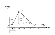
- FIG. 11 is a diagram for explaining the end determination of the transmission timing adjustment performed by the receiving device 500 shown in FIG.
- the timing control unit 509 starts adjusting the transmission timing when the slope of the time transition of the interference amount 701 of the OFDM symbol 302 of the received packet 601 becomes equal to or greater than the first threshold value.
- the received packet 601 at the time when the slope of the time transition of the interference amount 701 becomes equal to or higher than the first threshold value is defined as the z-th received packet 601.
- the timing control unit 509 holds the interference amount of the z-th received packet 601 as the end determination value 702.
- the timing control unit 509 calculates the difference between the interference amount 701 and the end determination value 702, and repeats the calculation of the control amount until the calculated difference becomes equal to or less than the second threshold value.
- the timing control unit 509 ends the calculation of the control amount.
- the difference between the interference amount 701 and the end determination value 702 is a correction continuation value 703 that is larger than the second threshold value.
- the correction end value 704 is such that the difference between the interference amount 701 and the end determination value 702 is equal to or less than the second threshold value.
- the interference measurement unit 507 calculates the amount of interference for each OFDM symbol 302.
- the plurality of subsystems 103-1, 103-2, 103-3 in the wireless communication system 100 are managed by a common administrator. Therefore, the administrator knows the transmission power in each of the subsystems 103-1, 103-2, and 103-3 in advance. Therefore, it is possible to calculate the maximum amount of interference observed per null symbol when packets are duplicated. Similarly, even when all the OFDM symbols 302 overlap, the maximum amount of interference that can be observed can be calculated. For example, as shown in FIG.
- the timing control unit 509 divides the maximum amount of interference received by one OFDM symbol 302 into four. Is used to calculate the correction amount for each OFDM symbol, which indicates how many symbols are corrected in the time axis direction from the measured interference amount. The timing control unit 509 calculates the control amount of the transmission timing by adding the results calculated by all the OFDM symbols 302 that need to be corrected.
- FIG. 12 is a diagram showing a second example of an interference state when the receiving device 500 shown in FIG. 8 corrects the transmission timing.
- the transmission timing of the subsystem 103-1 is gradually advanced due to the out-of-synchronization, so that the received packet 601 overlaps with the interference packet 602.
- FIG. 13 is a diagram showing the amount of interference measured by the control device 101-1 out of synchronization in the state shown in FIG. In the second example shown in FIG. 12, since the transmission timing of the subsystem 103-1 is earlier, the first OFDM symbol 302 which is the head side of the received packet 601 overlaps with the interference packet 602.
- the first OFDM symbol 302 of the received packet 601 overlaps with the interference packet 602.
- the interference amount 604 of the first OFDM symbol 302 is larger than the interference amount 605 to 607 of the second to fourth OFDM symbols 302. Since the specific operation of the timing control unit 509 is the same as that of the first example, detailed description thereof will be omitted here and will be briefly described.
- the interference area 603 is further expanded, and the first and second OFDM symbols 302 of the received packet 601 overlap with the interference packet 602.
- the interference amount 604 of the first OFDM symbol 302 and the interference amount 605 of the second OFDM symbol 302 are increased.
- the amount of change in the interference amounts 606 and 607 is smaller than that in the interference amounts 604 and 605.
- the timing control unit 509 increases the interference amount from the beginning of the received packet 601 based on the time transition of the interference amounts 604 to 607, the transmission timing of the out-of-synchronization subsystem 103-1 is advanced. It is determined that there is, and the control amount for delaying the transmission timing is output to the transmission control unit 201.
- the interference region 603 is reduced as a result of adjusting the transmission timing, and the second OFDM symbol 302 of the received packet 601 is in a state where it does not overlap with the interference packet 602.
- the first OFDM symbol 302 of the received packet 601 still overlaps with the interfering packet 602.
- the interference amount 605 of the second OFDM symbol 302 is reduced to the same extent as the interference amount 606,607.
- the interference amount 604 of the first OFDM symbol 302 is smaller than that of the y + 1th received packet 601 but is still larger than that of the interference amounts 605 to 607. Continue adjustments.
- the interference region 603 is further reduced as a result of adjusting the transmission timing, but the first OFDM symbol 302 still overlaps with the interference packet 602.
- the interference amount 604 of the first OFDM symbol 302 is reduced as compared with the y + second received packet 601 but is still large as compared with the interference amounts 605 to 607.
- the timing control unit 509 continues to adjust the transmission timing. Although not shown, the adjustment of the transmission timing is continued even after the y + 4th received packet 601 until the interference amount satisfies the condition.
- the functions of the transmitting device 200 and the receiving device 500 are realized by the processing circuit.
- These processing circuits may be realized by dedicated hardware, or may be control circuits using a CPU (Central Processing Unit).
- FIG. 14 is a diagram showing dedicated hardware for realizing the functions of the transmitting device 200 and the receiving device 500 according to the first embodiment.
- the processing circuit 90 is a single circuit, a composite circuit, a programmed processor, a parallel programmed processor, an ASIC (Application Specific Integrated Circuit), an FPGA (Field Programmable Gate Array), or a combination thereof.
- this control circuit is, for example, a control circuit 91 having the configuration shown in FIG.
- FIG. 15 is a diagram showing a configuration of a control circuit 91 for realizing the functions of the transmitting device 200 and the receiving device 500 according to the first embodiment.
- the control circuit 91 includes a processor 92 and a memory 93.
- the processor 92 is a CPU, and is also called an arithmetic unit, a microprocessor, a microcomputer, a DSP (Digital Signal Processor), or the like.
- the memory 93 is, for example, a non-volatile or volatile semiconductor memory such as RAM (Random Access Memory), ROM (Read Only Memory), flash memory, EPROM (Erasable Programmable ROM), EEPROM (registered trademark) (Electrically EPROM). Magnetic discs, flexible discs, optical discs, compact discs, mini discs, DVDs (Digital Versatile Disk), etc.
- RAM Random Access Memory
- ROM Read Only Memory
- flash memory EPROM (Erasable Programmable ROM), EEPROM (registered trademark) (Electrically EPROM).
- Magnetic discs flexible discs, optical discs, compact discs, mini discs, DVDs (Digital Versatile Disk), etc.
- control circuit 91 When the above processing circuit is realized by the control circuit 91, it is realized by the processor 92 reading and executing the program corresponding to the processing of each component stored in the memory 93.
- the memory 93 is also used as a temporary memory in each process executed by the processor 92.
- the computer program executed by the control circuit 91 may be provided via a communication path, or may be provided in a state of being stored in a storage medium.
- a part of the functions of the transmitting device 200 and the receiving device 500 may be realized by a dedicated circuit, and a part may be realized by a control circuit using a program and a CPU.
- the amount of interference can be measured by using the null symbol added to the received packet.
- the timing of measuring the interference amount is limited to the non-transmission section, and the communication is stopped in the non-transmission section, so that the transmission data rate is lowered.
- the amount of interference using the null symbol it is possible to measure the amount of interference without timing restrictions during communication, and the amount of interference while suppressing a decrease in the data rate. Can be measured.
- interference is reduced by controlling the transmission timing.
- a method of reducing interference it is conceivable to change the hopping pattern, but in this case, it is conceivable that the frequency channels used overlap with each other with a certain probability and the communication quality deteriorates.
- the method of controlling the transmission timing it is possible to perform correction so as to approach the synchronous state, and it is possible to reduce the interference more reliably than changing the hopping pattern.
- network synchronization is illustrated as a synchronization method for the entire wireless communication system 100, but the present embodiment is not limited to such an example.
- wireless synchronization may be performed between the control devices 101-1, 101-2, and 101-3.
- the wireless communication system 100 has three subsystems 103-1, 103-2, 103-3, but the number of subsystems is up to the number of hopping channels. Is not restricted.
- hopping patterns 104-1, 104-2, and 104-3 using 8 channels and having 8 sequences as one cycle are illustrated, but the present embodiment is not limited to such an example.
- the number of hopping channels and the hopping pattern are not limited to the above examples, and may have any configuration.
- the number of hopping channels is the number of subsystems that can communicate with each other in the system at the same time without interference. Therefore, the larger the number of hopping channels, the more subsystems can communicate without interference.
- one transmission packet 301 includes four OFDM symbols 302, and one OFDM symbol 302 is composed of a total of 32 symbols in which 8 subcarriers are arranged in the frequency axis direction and 4 symbols are arranged in the time axis direction.
- the present embodiment is not limited to such an example.
- the arrangement of the null symbol 402 is also an example, and is not limited to the example described above.
- the packet configuration, the number of null symbol mappings, the mapping method, and the like are not limited to the above examples, and any method can be used.
- the interference amount processing unit 508 averages the measured interference amount of each null symbol 402 for each OFDM symbol 302, but this embodiment is not limited to such an example.
- the interference amount processing unit 508 can average the interference amount for each predetermined unit.
- the interference amount processing unit 508 may average the interference amount for each predetermined time, or may average the interference amount for each predetermined number of symbols.
- the processing result of the interference amount processing unit 508 is used for correcting the transmission timing, but this embodiment is not limited to such an example.
- the processing result of the interference amount processing unit 508 may be used to monitor the interference in the packet reception time, and the out-of-synchronization control device 101-1 returns to the synchronization based on the transition of the interference amount. It may be used to determine the correct transmission timing for this.
- the timing control unit 509 plots the processing result of the interference amount processing unit 508 on the time axis, and calculates the control amount of the transmission timing by using the time transition of the interference amount.
- the present embodiment is not limited to such an example.
- the regression line calculated by using the least squares method is used for the interference amount for each received packet 601 and each OFDM symbol 302 instead of simply the time transition.
- the standard deviation in addition to the regression line, it is possible to obtain the control amount of the transmission timing with higher accuracy.
- the timing control unit 509 holds the interference amount when the inclination becomes equal to or higher than the first threshold value as the end determination value 702 based on the time transition of the interference amount, and holds the end determination value.
- 702 it was decided to use 702 to determine whether or not to end the correction of the transmission timing
- the present embodiment is not limited to such an example.
- a third threshold value may be set for the interference amount, and when the interference amount becomes equal to or less than the third threshold value, the correction of the transmission timing may be terminated.
- the wireless communication devices are the control devices 101-1, 101-2, 101-3 and the controlled devices 102-1, 102-2, 102-3.
- Embodiments are not limited to such examples.
- the technique of this embodiment can be applied to a wireless communication device capable of communicating using frequency hopping.
- the configuration shown in the above embodiments is an example, and can be combined with another known technique, can be combined with each other, and does not deviate from the gist. It is also possible to omit or change a part of the configuration.
- 90 processing circuit 91 control circuit, 92 processor, 93 memory, 100 wireless communication system, 101-1, 101-2, 101-3 control device, 102-1, 102-2, 102-3 controlled device, 103- 1,103-2,103-3 Subsystem, 104-1,104-2,104-3 Hopping pattern, 200 Transmitter, 201 Transmission control unit, 202 Coding unit, 203 Modulation unit, 204 Frequency mapping unit, 205 IFFT unit, 206 high frequency transmission processing unit, 207 transmission antenna unit, 301 transmission packet, 302 OFDM symbol, 401 modulation signal, 402 null symbol, 500 receiver, 501 reception antenna unit, 502 high frequency reception processing unit, 503 FFT unit, 504 Null discrimination unit, 505 demodulation unit, 506 decoding unit, 507 interference measurement unit, 508 interference amount processing unit, 509 timing control unit, 601 reception packet, 602 interference packet, 603 interference area, 604,605,606,607,701 interference Amount, 702 end judgment value, 703 correction continuation value, 704 correction end value
Landscapes
- Engineering & Computer Science (AREA)
- Computer Networks & Wireless Communication (AREA)
- Signal Processing (AREA)
- Computer Security & Cryptography (AREA)
- Mobile Radio Communication Systems (AREA)
Abstract
無線通信装置は、予め定められたホッピングパターンを用いて、使用する周波数チャネルを切り替えながら対向する無線通信装置と通信し、対向する無線通信装置からの受信パケットに含まれるヌルシンボルの位置を判別するヌル判別部(504)と、受信パケットに含まれるヌルシンボルを用いて干渉量を測定する干渉測定部(507)と、を備えることを特徴とする。
Description
本開示は、周波数ホッピングを用いる無線通信装置、無線通信システム、制御回路、記憶媒体および無線通信方法に関する。
近年、無線通信の発達に伴い、従来、有線通信が用いられてきた機器間の制御などに、無線通信が用いられるようになっている。制御用通信を無線化することで、低コスト化、メンテナンス性の向上といった効果が期待できる。
無線通信システム内に近接する複数の無線通信装置が含まれる場合、干渉を避けるために、同時に通信する無線通信装置が使用する周波数帯域が重複しないように制御する必要がある。例えば、予め定められた周波数帯域の中から、通信に使用する周波数チャネルを高速で切り替えながら通信する周波数ホッピングを用いる場合、無線通信装置間で同期を取りながら、互いに異なるホッピングパターンを用いて通信に使用する周波数チャネルを切り替えることで、互いに干渉することなく同時に通信することが可能になる。
しかしながら、故障などによる同期外れが発生すると、他の無線通信装置と使用する周波数チャネルの重複が生じて、干渉を引き起こす場合がある。特許文献1には、予め定められたホッピングパターンに従って使用する周波数チャネルを切り替えながら通信する無線通信装置において、無送信区間を利用して干渉量を測定し、干渉量が増加するとホッピングパターンを変更することで、干渉を低減する技術が開示されている。
しかしながら、特許文献1に開示された技術では、通信中に無送信区間を設けて干渉量を測定するため、送信データレートが低下するという問題があった。
本開示は、上記に鑑みてなされたものであって、周波数ホッピング方式を使用するシステムにおいて、送信データレートの低下を抑制しつつ、干渉量を測定することが可能な無線通信装置を得ることを目的とする。
上述した課題を解決し、目的を達成するために、本開示にかかる無線通信装置は、予め定められたホッピングパターンを用いて、使用する周波数チャネルを切り替えながら対向する無線通信装置と通信し、対向する無線通信装置からの受信パケットに含まれるヌルシンボルの位置を判別するヌル判別部と、受信パケットに含まれるヌルシンボルを用いて干渉量を測定する干渉測定部と、を備えることを特徴とする。
本開示にかかる無線通信装置は、送信データレートの低下を抑制しつつ、干渉量を測定することが可能であるという効果を奏する。
以下に、本開示の実施の形態にかかる無線通信装置、無線通信システム、制御回路、記憶媒体および無線通信方法を図面に基づいて詳細に説明する。
実施の形態1.
図1は、実施の形態1にかかる無線通信システム100の構成を示す図である。無線通信システム100は、複数の制御装置101-1,101-2,101-3と、複数の被制御装置102-1,102-2,102-3とを有する。制御装置101-1,101-2,101-3および被制御装置102-1,102-2,102-3のそれぞれは、無線通信装置の一例である。制御装置101-1および被制御装置102-1は、サブシステム103-1を構成している。制御装置101-2および被制御装置102-2は、サブシステム103-2を構成している。制御装置101-3および被制御装置102-3は、サブシステム103-3を構成している。
図1は、実施の形態1にかかる無線通信システム100の構成を示す図である。無線通信システム100は、複数の制御装置101-1,101-2,101-3と、複数の被制御装置102-1,102-2,102-3とを有する。制御装置101-1,101-2,101-3および被制御装置102-1,102-2,102-3のそれぞれは、無線通信装置の一例である。制御装置101-1および被制御装置102-1は、サブシステム103-1を構成している。制御装置101-2および被制御装置102-2は、サブシステム103-2を構成している。制御装置101-3および被制御装置102-3は、サブシステム103-3を構成している。
サブシステム103-1,103-2,103-3のそれぞれは、予め定められたホッピングパターンを用いて、使用する周波数チャネルを切り替えながら対向する無線通信装置と無線通信する。なお、制御装置101-1と対向する無線通信装置は被制御装置102-1であり、制御装置101-2と対向する無線通信装置は被制御装置102-2であり、制御装置101-3と対向する無線通信装置は被制御装置102-3である。例えば、制御装置101-1は、対向する被制御装置102-1を制御するためのコマンドを無線通信で送信する。被制御装置102-1は、制御装置101-1に制御応答等のデータを無線通信で送信する。制御装置101-2は、対向する被制御装置102-2を制御するためのコマンドを無線通信で送信する。被制御装置102-2は、制御装置101-2に制御応答等のデータを無線通信で送信する。制御装置101-3は、対向する被制御装置102-3を制御するためのコマンドを無線通信で送信する。被制御装置102-3は、制御装置101-3に制御応答等のデータを無線通信で送信する。制御装置101-1,101-2,101-3は、ネットワーク同期がとれており、互いの動作タイミングは同期している。
図2は、図1に示す無線通信システム100が使用する周波数チャネルを示す図である。図2に示す例では、チャネルCH0からチャネルCH7の8チャンネルが用いられている。サブシステム103-1,103-2,103-3毎に、使用するホッピングパターンは異なり、同期がとれている場合には、同時に使用される周波数チャネルが重複しないようになっている。サブシステム103-1のホッピングパターン104-1は、チャネルCH0,CH2,CH4,CH7,CH5,CH1,CH6,CH3の順に使用される周波数チャネルが変化する。サブシステム103-2のホッピングパターン104-2は、チャネルCH1,CH6,CH3,CH0,CH2,CH4,CH7,CH5の順に使用される周波数チャネルが変化する。サブシステム103-3のホッピングパターン104-3は、チャネルCH4,CH7,CH5,CH1,CH6,CH3,CH0,CH2の順に使用される周波数チャネルが変化する。なお上記では、使用される周波数チャネルの変化順は同一であって、3つずつオフセットしたホッピングパターンが使用されることとしたが、本実施の形態はかかる例に限定されない。同期がとれているときに、同時に使用される周波数チャネルが重複しなければよい。
図3は、図1に示す無線通信システム100において同期が外れた状態を示す図である。図3では、故障等が原因で、サブシステム103-1がネットワーク同期から外れた状態を示している。図4は、図3に示す状態の無線通信システム100が使用する周波数チャネルを示す図である。ここでは、サブシステム103-2,103-3は同期がとれており、図2に示す状態と同様に、サブシステム103-2,103-3間では、同時に使用する周波数チャネルの重複は生じない。同期が外れたサブシステム103-1は、2~3シーケンス程度の遅れが生じており、この場合、サブシステム103-2と周波数チャネルの重複104-4が発生している。本実施の形態では、同期外れが検出されると、送信タイミングを調整することで、周波数チャネルの重複を低減する。以下、周波数チャネルの重複を低減するための構成について説明する。
図5は、図1に示す無線通信装置が備える送信装置200の構成を示す図である。送信装置200は、送信制御部201と、符号化部202と、変調部203と、周波数マッピング部204と、IFFT(Inverse Fast Fourier Transform:逆高速フーリエ変換)部205と、高周波送信処理部206と、送信アンテナ部207とを有する。
送信制御部201が送信指示を行うことで、送信装置200は送信処理を開始する。送信開始とともに、符号化部202は、情報ビットに符号化処理を行い、符号化後の信号を変調部203に出力する。変調部203は、例えば、PSK(Phase Shift Keying)変調などを用いて、信号の変調処理を行い、変調信号を周波数マッピング部204に出力する。
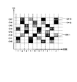
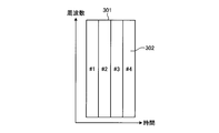
周波数マッピング部204は、変調信号を送信するサブキャリアにマッピングする。このとき周波数マッピング部204は、変調信号とともにヌルシンボルを配置していく。図6は、図5に示す送信装置200の送信パケット301の構成を示す図である。1つの送信パケット301は、複数の変調シンボルであるOFDMシンボル302、ここでは4つのOFDMシンボル302を含む。図7は、図6に示すOFDMシンボル302の構成を示す図である。1つのOFDMシンボル302は、周波数軸方向に8サブキャリア、時間軸方向に4シンボル並べた合計32シンボルによって構成されている。変調信号401およびヌルシンボル402が、OFDMシンボル302内に周波数マッピングされている。
図7では、変調信号401に対して、ヌルシンボル402を4サブキャリア飛ばしで配置し、時間軸方向に1シンボルずれる毎にサブキャリア方向に1オフセットさせた例が示されている。送信パケット301にヌルシンボル402をマッピングして送信することで、受信側でこのヌルシンボル402を用いて干渉量を測定することが可能になる。
なお、無線通信システム100内で同時に送信される複数の送信パケット301のヌルシンボル402の位置が同じであった場合、同期外れによって送信パケット301が完全に重なると、ヌルシンボル402の位置が完全に重なってしまい、干渉量を測定することができなくなる。このため、周波数マッピング部204が送信パケット301にヌルシンボル402を付加する位置を、サブシステム103-1,103-2,103-3毎に異なるようにすることで、上記のように干渉量を測定することができない状態を回避することができる。
図5の説明に戻る。周波数マッピング部204は、周波数マッピング処理を行った後の信号を、IFFT部205に出力する。IFFT部205は、周波数マッピング処理を行った後の信号を、逆フーリエ変換して、逆フーリエ変換後の信号を高周波送信処理部206に出力する。IFFT部205が出力する信号は、デジタル信号となる。高周波送信処理部206は、デジタル信号をアナログ信号に変換する。また高周波送信処理部206は、アナログ信号の周波数をキャリア周波数に変換して、送信アンテナ部207から送信する。
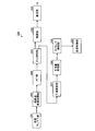
図8は、図1に示す無線通信装置が備える受信装置500の構成を示す図である。受信装置500は、受信アンテナ部501と、高周波受信処理部502と、FFT(Fast Fourier Transform)部503と、ヌル判別部504と、復調部505と、復号部506と、干渉測定部507と、干渉量処理部508と、タイミング制御部509とを有する。
受信アンテナ部501は、送信装置200が送信した信号を受信し、受信信号を高周波受信処理部502に出力する。高周波受信処理部502は、アナログ信号である受信信号のレベル調整を行う。また高周波受信処理部502は、受信信号の周波数をベースバンドに周波数変換する。また高周波受信処理部502は、アナログ信号をデジタル信号に変換してFFT部503に出力する。FFT部503は、受信信号をフーリエ変換して、ヌル判別部504に出力する。
ヌル判別部504は、受信信号中の受信パケットに含まれるヌルシンボルの位置を判別する。受信パケットは、図7に示すように、変調信号401とヌルシンボル402とがマッピングされている。ヌル判別部504は、受信パケットのシンボルが変調信号401であるかヌルシンボル402であるかを判別し、変調信号401を復調部505へ出力し、ヌルシンボル402を干渉測定部507へ出力する。
復調部505は、受信信号を復調処理し、復調処理後の受信信号を復号部506に出力する。復号部506は、復調処理後の受信信号を復号処理し、復号されたデータを出力する。
干渉測定部507は、ヌル判別部504が出力したヌルシンボル402を用いて干渉量を測定する。ヌルシンボル402の送信時の値は「0」であるため、ヌルシンボル402を用いて測定した値は、ヌルシンボル402の時間および周波数における配置位置の干渉量となる。干渉測定部507は、各ヌルシンボル402の干渉量の測定値を干渉量処理部508に出力する。
干渉量処理部508は、測定された各ヌルシンボル402の干渉量を処理して送信タイミングの制御量を算出するために用いる値を生成する。例えば、干渉量処理部508は、予め定められたパケット位置ごとに干渉量を平均化し、平均化された値をタイミング制御部509に出力する。干渉量処理部508は、例えば、図6に示すOFDMシンボル302毎に干渉量を平均化することができる。OFDMシンボル302が図7に示す構成を有している場合、干渉量処理部508は、干渉量の8個の測定値を平均化することになる。
タイミング制御部509は、干渉量に基づいて、送信パケットを送信する送信タイミングの制御量を算出する。タイミング制御部509は、例えば、干渉量処理部508がOFDMシンボル302毎に平均化した干渉量を、受信パケット毎にプロットすることで得られる干渉量の時間推移を用いて、送信タイミングの制御量を推定する。タイミング制御部509は、算出した送信タイミングの制御量を、送信制御部201に出力する。
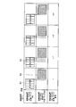
続いて、タイミング制御部509による送信タイミングの補正について説明する。本実施の形態では、被制御装置102-1~102-3には少なくとも送信装置200が備えられており、制御装置101-1~101-3には受信装置500および送信装置200が備えられているとする。なお、図9は、図8に示す受信装置500が送信タイミングを補正する場合の干渉状態の第1の例を示す図である。図9は、同期を外れた制御装置101-1が受信するパケットについて示している。また、ここでは、被制御装置102-1の送信装置200が、送信パケット301にヌルシンボル402を付加しているとする。被制御装置102-1からの受信パケット番号xにおいて、同期を外れた制御装置101-1が受信する被制御装置102-1からの受信パケット601の受信タイミングが遅れている。このため、受信パケット601が被制御装置102-2からの受信パケットである干渉パケット602と干渉する。
図10は、図9に示す状態において同期を外れた制御装置101-1が測定する干渉量を示す図である。ここでは、制御装置101-1の受信装置500は、受信パケット601を受信するときに、ヌルシンボル402を用いて干渉量を測定し、OFDMシンボル302毎に平均化した干渉量の推移が示されている。図10には、1番目のOFDMシンボル302の干渉量604、2番目のOFDMシンボル302の干渉量605、3番目のOFDMシンボル302の干渉量606、4番目のOFDMシンボル302の干渉量607が示されている。
x番目の受信パケットにおいて、OFDMシンボル302毎に干渉量を平均化した場合、被制御装置102-1からのパケットの受信が遅れたことで、近接する被制御装置102-2からの受信パケットの一部と重なり、4番目のOFDMシンボル302の干渉量607が測定される。このとき、干渉量604,605,606が「0」ではないのは、無線通信システム100の外部からの干渉が測定されているからと考えられる。
図9を参照すると、x+1番目の受信パケット601では、さらに、被制御装置102-1からのパケットの受信が遅れ、被制御装置102-1からの受信パケット601と干渉パケット602との干渉領域603が拡大している。これにより、受信パケット601の4番目のOFDMシンボル302だけでなく、3番目のOFDMシンボル302も干渉パケット602と干渉している。図10を参照すると、受信パケットx+1において、4番目のOFDMシンボル302の干渉量607および3番目のOFDMシンボル302の干渉量606が増大しており、1番目のOFDMシンボル302の干渉量604および2番目のOFDMシンボル302の干渉量605の変化は、干渉量606,607と比較して小さい。このときタイミング制御部509は、干渉量604~607の時間推移から、受信パケット601の末尾から干渉量が増えているため、同期を外れたサブシステム103-1の送信タイミングが遅れていると判定し、制御装置101-1の送信制御部201に送信タイミングを早めるための制御量を出力する。制御量の算出方法については、後述する。制御装置101-1の送信制御部201は、入力された制御量に基づいて、送信タイミングを制御することで、被制御装置102-1における受信タイミングも補正され、これにより干渉が抑圧される。また、これにより、被制御装置102-1からの次回以降の送信タイミングも補正されるので、サブシステム103-1の全体の通信タイミングを補正することができ、無線通信システム100内の他のサブシステム103-2,103-3とのシステム内干渉抑圧を実現する。
図9を参照すると、x+2番目の受信パケット601では、送信タイミングが調整されたことによって、被制御装置102-1からの受信パケット601の受信タイミングが早まり、受信パケット601の3番目のOFDMシンボル302が干渉パケット602と干渉しない状態となっており、4番目のOFDMシンボル302と干渉パケット602との干渉領域603が小さくなっている。図10を参照すると、3番目のOFDMシンボル302の干渉量606および4番目のOFDMシンボル302の干渉量607が減少している。特に、3番目のOFDMシンボル302の干渉量606は、干渉量604,605と同程度まで低下している。このときタイミング制御部509は、干渉量607がまだ大きいことから、同期を外れたサブシステム103-1の送信タイミングがまだ遅れていると判定し、送信制御部201に送信タイミングを早めるための制御量を出力する。
図9を参照すると、x+3番目の受信パケット601では、さらに送信タイミングが調整されたことによって、被制御装置102-1からの受信パケット601の受信タイミングがさらに早まり、受信パケット601の4番目のOFDMシンボル302と干渉パケット602との干渉領域603がさらに小さくなっている。図10を参照すると、4番目のOFDMシンボル302の干渉量607は、x+2番目の受信パケット601よりもさらに小さくなっている。ここでは、x+3番目の受信パケット601においても、干渉量607が残っているため、さらに繰り返し送信タイミングの調整を繰り返すことで、干渉量607をさらに低減することができる。
図11は、図8に示す受信装置500が行う送信タイミングの調整の終了判定を説明するための図である。タイミング制御部509は、受信パケット601のOFDMシンボル302の干渉量701の時間推移の傾きが第1の閾値以上となった場合、送信タイミングの調整を開始する。ここで、干渉量701の時間推移の傾きが第1の閾値以上となった時点の受信パケット601をz番目の受信パケット601とする。このとき、タイミング制御部509は、z番目の受信パケット601の干渉量を終了判定値702として保持する。タイミング制御部509は、干渉量701と終了判定値702との差異を算出し、算出した差異が第2の閾値以下となるまで、制御量の算出を繰り返す。タイミング制御部509は、干渉量701と終了判定値702との差異が第2の閾値以下となった場合、制御量の算出を終了する。図11の例では、z+1番目の受信パケット601およびz+2番目の受信パケット601では、干渉量701と終了判定値702との差異が第2の閾値よりも大きい補正継続値703となる。z+3番目の受信パケット601では、干渉量701と終了判定値702との差異が第2の閾値以下である補正終了値704となる。
ここで、図8に示す受信装置500が行う制御量の算出について説明する。干渉測定部507は、OFDMシンボル302毎に干渉量を算出する。本実施の形態では、無線通信システム100内の複数のサブシステム103-1,103-2,103-3は共通の管理者によって管理されている。このため、管理者は、サブシステム103-1,103-2,103-3のそれぞれにおける送信パワーを事前に分かっている。したがって、パケット同士が重複した場合のヌルシンボル1つあたりが観測する最大の干渉量を算出することができる。同様に、OFDMシンボル302が全て重複した場合においても、観測される最大の干渉量を算出することができる。例えば、図7に示すように、1つのOFDMシンボル302内で時間軸方向に4シンボルが並んでいる場合、タイミング制御部509は、1つのOFDMシンボル302が受ける最大の干渉量を4分割した値を用いて、測定した干渉量から時間軸方向に何シンボル分の補正を行うかを示すOFDMシンボル毎の補正量を算出する。タイミング制御部509は、補正が必要な全てのOFDMシンボル302で算出した結果を加算して、送信タイミングの制御量を算出する。
図12は、図8に示す受信装置500が送信タイミングを補正する場合の干渉状態の第2の例を示す図である。第2の例では、図9に示す第1の例と異なってサブシステム103-1の送信タイミングが同期外れにより徐々に早まるため、受信パケット601が、干渉パケット602と重複してしまう。
図13は、図12に示す状態において同期を外れた制御装置101-1が測定する干渉量を示す図である。図12に示す第2の例では、サブシステム103-1の送信タイミングが早まっているため、受信パケット601の先頭側である1番目のOFDMシンボル302から干渉パケット602と重複する。
図12を参照すると、y番目の受信パケット601では、受信パケット601の1番目のOFDMシンボル302が干渉パケット602と重複している。この場合、図13を参照すると、1番目のOFDMシンボル302の干渉量604は、2~4番目のOFDMシンボル302の干渉量605~607と比較して大きい。なお、タイミング制御部509の具体的な動作については、第1の例と同様であるため、ここでは詳細な説明を省略し、簡単に説明する。
続いてy+1番目の受信パケット601では、図12を参照すると、干渉領域603がさらに拡大しており、受信パケット601の1番目および2番目のOFDMシンボル302が干渉パケット602と重複している。この場合、図13を参照すると、1番目のOFDMシンボル302の干渉量604および2番目のOFDMシンボル302の干渉量605が増大している。干渉量606,607の変化量は、干渉量604,605と比較して小さい。このときタイミング制御部509は、干渉量604~607の時間推移に基づいて、受信パケット601の先頭から干渉量が増大しているため、同期を外れたサブシステム103-1の送信タイミングが早まっていると判定し、送信制御部201に送信タイミングを遅らせるための制御量を出力する。
図12を参照すると、y+2番目の受信パケット601では、送信タイミングを調整した結果、干渉領域603が減少しており、受信パケット601の2番目のOFDMシンボル302が干渉パケット602と重複しない状態となっており、受信パケット601の1番目のOFDMシンボル302が未だ干渉パケット602と重複している。この場合、図13を参照すると、2番目のOFDMシンボル302の干渉量605は、干渉量606,607と同程度に減少している。1番目のOFDMシンボル302の干渉量604は、y+1番目の受信パケット601と比較して減少しているが、未だ干渉量605~607と比較して大きいため、タイミング制御部509は、送信タイミングの調整を継続する。
図12を参照すると、y+3番目の受信パケット601では、送信タイミングを調整した結果、干渉領域603がさらに減少しているが、1番目のOFDMシンボル302は未だ干渉パケット602と重複している。この場合、図13を参照すると、1番目のOFDMシンボル302の干渉量604は、y+2番目の受信パケット601と比較して減少しているが、未だ干渉量605~607と比較して大きいため、タイミング制御部509は、送信タイミングの調整を継続する。図示していないが、y+4番目の受信パケット601以降も、干渉量が条件を満たすまで、送信タイミングの調整は継続される。
続いて、実施の形態1にかかる送信装置200および受信装置500のハードウェア構成について説明する。送信装置200および受信装置500の機能は、処理回路により実現される。これらの処理回路は、専用のハードウェアにより実現されてもよいし、CPU(Central Processing Unit)を用いた制御回路であってもよい。
上記の処理回路が、専用のハードウェアにより実現される場合、これらは、図14に示す処理回路90により実現される。図14は、実施の形態1にかかる送信装置200および受信装置500の機能を実現するための専用のハードウェアを示す図である。処理回路90は、単一回路、複合回路、プログラム化したプロセッサ、並列プログラム化したプロセッサ、ASIC(Application Specific Integrated Circuit)、FPGA(Field Programmable Gate Array)、またはこれらを組み合わせたものである。
上記の処理回路が、CPUを用いた制御回路で実現される場合、この制御回路は例えば図15に示す構成の制御回路91である。図15は、実施の形態1にかかる送信装置200および受信装置500の機能を実現するための制御回路91の構成を示す図である。図15に示すように、制御回路91は、プロセッサ92と、メモリ93とを備える。プロセッサ92は、CPUであり、演算装置、マイクロプロセッサ、マイクロコンピュータ、DSP(Digital Signal Processor)などとも呼ばれる。メモリ93は、例えば、RAM(Random Access Memory)、ROM(Read Only Memory)、フラッシュメモリ、EPROM(Erasable Programmable ROM)、EEPROM(登録商標)(Electrically EPROM)などの不揮発性または揮発性の半導体メモリ、磁気ディスク、フレキシブルディスク、光ディスク、コンパクトディスク、ミニディスク、DVD(Digital Versatile Disk)などである。
上記の処理回路が制御回路91により実現される場合、プロセッサ92がメモリ93に記憶された、各構成要素の処理に対応するプログラムを読み出して実行することにより実現される。また、メモリ93は、プロセッサ92が実行する各処理における一時メモリとしても使用される。なお、制御回路91が実行するコンピュータプログラムは、通信路を介して提供されてもよいし、記憶媒体に記憶された状態で提供されてもよい。
また、送信装置200および受信装置500の機能の一部を専用回路で実現し、一部をプログラムおよびCPUを用いた制御回路で実現してもよい。
以上説明したように、本実施の形態によれば、受信パケットに付加されたヌルシンボルを用いて、干渉量を測定することができる。無送信区間を設けて干渉量を測定する場合、干渉量を測定するタイミングが無送信区間に限定されると共に、無送信区間では、通信が停止されるため、送信データレートが低下してしまう。これに対して、ヌルシンボルを用いて干渉量を測定する場合、通信中であれば、タイミングの制限なく干渉量を測定することが可能であると共に、データレートの低下を抑制しつつ、干渉量を測定することが可能になる。
また、本実施の形態によれば、送信タイミングを制御することで、干渉を低減している。干渉を低減する方法としては、ホッピングパターンを変更することも考えられるが、この場合、一定の確率で使用する周波数チャネルが重複し、通信品質が低下することが考えられる。これに対して、送信タイミングを制御する方式では、同期状態に近づけるように補正を行うことが可能であり、ホッピングパターンを変更するよりも確実に干渉を低減することが可能である。
なお、上記の実施の形態では、無線通信システム100全体の同期方式として、ネットワーク同期を例示したが、本実施の形態はかかる例に限定されない。例えば、制御装置101-1,101-2,101-3間で無線を用いた同期を行ってもよい。また、上記の実施の形態では、無線通信システム100は、3つのサブシステム103-1,103-2,103-3を有することとしたが、ホッピングチャネル数分までであれば、サブシステムの数は制限されない。
なお、上記の実施の形態では、8チャネルを用いて8シーケンスを1周期としたホッピングパターン104-1,104-2,104-3を例示したが、本実施の形態はかかる例に限定されない。ホッピングチャネル数およびホッピングパターンは、上記の例に限定されず、任意の構成とすることができる。なお、ホッピングチャネル数は、同時にシステム内で干渉なく通信できるサブシステムの数となる。このため、ホッピングチャネル数が多いほど、多くのサブシステムが干渉なく通信することが可能になる。
また、上記の実施の形態では、1つの送信パケット301が4つのOFDMシンボル302を含み、1つのOFDMシンボル302は、周波数軸方向に8サブキャリア、時間軸方向に4シンボル並べた合計32シンボルから構成されていることとしたが、本実施の形態はかかる例に限定されない。また、ヌルシンボル402の配置についても、上記は一例であり、説明した例に限定されない。パケットの構成、ヌルシンボルのマッピング数、マッピング方法などについては、上記の例に限定されず、任意の方法を用いることができる。
また、上記の実施の形態では、干渉量処理部508は、測定した各ヌルシンボル402の干渉量をOFDMシンボル302毎に平均化しているが、本実施の形態はかかる例に限定されない。干渉量処理部508は、予め定められた単位毎に干渉量を平均化することができる。例えば、干渉量処理部508は、予め定められた時間毎に干渉量を平均化してもよいし、予め定められたシンボル数毎に干渉量を平均化してもよい。
また、上記の実施の形態では、干渉量処理部508の処理結果を、送信タイミングの補正に用いているが、本実施の形態はかかる例に限定されない。例えば、干渉量処理部508の処理結果は、パケット受信時間における干渉を監視するために用いられてもよいし、干渉量の推移に基づいて、同期を外れた制御装置101-1が同期に復帰するための正しい送信タイミングを判定するために用いられてもよい。
また、上記の実施の形態では、タイミング制御部509は、干渉量処理部508の処理結果を時間軸にプロットし、干渉量の時間推移を用いて、送信タイミングの制御量を算出することとしたが、本実施の形態はかかる例に限定されない。例えば、無線通信システム100の外からの干渉変動が大きい場合、単に時間推移でなく受信パケット601毎、OFDMシンボル302毎の干渉量に対して、最小二乗法を用いて算出した回帰直線を活用したり、回帰直線に加えて標準偏差を活用することで、送信タイミングの制御量をより精度高く求めることが可能になる。
また、上記の実施の形態では、タイミング制御部509は、干渉量の時間推移に基づいて、傾きが第1の閾値以上となったときの干渉量を終了判定値702として保持し、終了判定値702を用いて、送信タイミングの補正を終了するか否かを判定することとしたが、本実施の形態はかかる例に限定されない。例えば、干渉量に第3の閾値を設け、干渉量が第3の閾値以下となった場合に、送信タイミングの補正を終了してもよい。
また、上記の実施の形態では、無線通信装置は、制御装置101-1,101-2,101-3および被制御装置102-1,102-2,102-3であることとしたが、本実施の形態はかかる例に限定されない。周波数ホッピングを用いて通信可能な無線通信装置に本実施の形態の技術を適用可能である。
以上の実施の形態に示した構成は、一例を示すものであり、別の公知の技術と組み合わせることも可能であるし、実施の形態同士を組み合わせることも可能であるし、要旨を逸脱しない範囲で、構成の一部を省略、変更することも可能である。
90 処理回路、91 制御回路、92 プロセッサ、93 メモリ、100 無線通信システム、101-1,101-2,101-3 制御装置、102-1,102-2,102-3 被制御装置、103-1,103-2,103-3 サブシステム、104-1,104-2,104-3 ホッピングパターン、200 送信装置、201 送信制御部、202 符号化部、203 変調部、204 周波数マッピング部、205 IFFT部、206 高周波送信処理部、207 送信アンテナ部、301 送信パケット、302 OFDMシンボル、401 変調信号、402 ヌルシンボル、500 受信装置、501 受信アンテナ部、502 高周波受信処理部、503 FFT部、504 ヌル判別部、505 復調部、506 復号部、507 干渉測定部、508 干渉量処理部、509 タイミング制御部、601 受信パケット、602 干渉パケット、603 干渉領域、604,605,606,607,701 干渉量、702 終了判定値、703 補正継続値、704 補正終了値。
Claims (10)
- 予め定められたホッピングパターンを用いて、使用する周波数チャネルを切り替えながら対向する無線通信装置と通信する無線通信装置であって、
前記対向する無線通信装置からの受信パケットに含まれるヌルシンボルの位置を判別するヌル判別部と、
前記受信パケットに含まれるヌルシンボルを用いて干渉量を測定する干渉測定部と、
を備えることを特徴とする無線通信装置。 - 前記干渉量に基づいて、前記対向する無線通信装置へ送信パケットを送信する送信タイミングの制御量を算出するタイミング制御部、
をさらに備えることを特徴とする請求項1に記載の無線通信装置。 - 前記受信パケットは、変調信号およびヌルシンボルのそれぞれが周波数マッピングされた変調シンボルを含み、
前記干渉測定部は、1つの前記受信パケットを構成する変調シンボル毎の干渉量を測定し、
前記タイミング制御部は、前記変調シンボル毎の干渉量と、予め保持している干渉量の最大値とに基づいて、前記変調シンボル毎の補正量を算出し、前記変調シンボル毎の補正量に基づいて、前記制御量を算出することを特徴とする請求項2に記載の無線通信装置。 - 前記タイミング制御部は、前記受信パケット毎の干渉量の傾きが第1閾値以上となった場合、前記制御量を算出することを特徴とする請求項2または3に記載の無線通信装置。
- 前記タイミング制御部は、前記受信パケット毎の干渉量の傾きが前記第1閾値以上となったときの干渉量を終了判定値として保持し、前記制御量を繰り返して算出し、干渉量と前記終了判定値との差が第2閾値以下となると前記制御量の算出を終了することを特徴とする請求項4に記載の無線通信装置。
- 請求項1から5のいずれか1項に記載の無線通信装置と、前記無線通信装置と対向する無線通信装置と、を含むサブシステムを複数備え、
前記サブシステム毎に異なるホッピングパターンを用いて通信することを特徴とする無線通信システム。 - 送信パケットに前記ヌルシンボルを付加する位置は、前記サブシステム毎に異なることを特徴とする請求項6に記載の無線通信システム。
- 予め定められたホッピングパターンを用いて、使用する周波数チャネルを切り替えながら対向する無線通信装置と通信する無線通信装置を制御する制御回路であって、
前記対向する無線通信装置からの受信パケットに含まれるヌルシンボルの位置を判別するステップと、
前記受信パケットに含まれるヌルシンボルを用いて干渉量を測定するステップと、
を無線通信装置に実行させることを特徴とする制御回路。 - 予め定められたホッピングパターンを用いて、使用する周波数チャネルを切り替えながら対向する無線通信装置と通信する無線通信装置を制御するプログラムを記憶した記憶媒体であって、該プログラムは、
前記対向する無線通信装置からの受信パケットに含まれるヌルシンボルの位置を判別するステップと、
前記受信パケットに含まれるヌルシンボルを用いて干渉量を測定するステップと、
を無線通信装置に実行させることを特徴とする記憶媒体。 - 一対の無線通信装置を含む複数のサブシステムのそれぞれが、異なるホッピングパターンを用いて、使用する周波数チャネルを切り替えながら通信する無線通信方法であって、
前記一対の無線通信装置のうちの1つが、
対向する無線通信装置からの受信パケットに含まれるヌルシンボルの位置を判別するステップと、
前記受信パケットに含まれるヌルシンボルを用いて干渉量を測定するステップと、
を実行することを特徴とする無線通信方法。
Priority Applications (5)
| Application Number | Priority Date | Filing Date | Title |
|---|---|---|---|
| JP2021578144A JP7038937B2 (ja) | 2020-03-10 | 2020-03-10 | 無線通信装置および無線通信システム |
| DE112020006438.7T DE112020006438B4 (de) | 2020-03-10 | 2020-03-10 | Funkkommunikationseinrichtung und funkkommunikationssystem |
| PCT/JP2020/010176 WO2021181499A1 (ja) | 2020-03-10 | 2020-03-10 | 無線通信装置、無線通信システム、制御回路、記憶媒体および無線通信方法 |
| CN202080097963.1A CN115244861B (zh) | 2020-03-10 | 2020-03-10 | 无线通信装置和无线通信系统 |
| US17/858,823 US11996880B2 (en) | 2020-03-10 | 2022-07-06 | Radio communication device, radio communication system, control circuit, storage medium, and radio communication method |
Applications Claiming Priority (1)
| Application Number | Priority Date | Filing Date | Title |
|---|---|---|---|
| PCT/JP2020/010176 WO2021181499A1 (ja) | 2020-03-10 | 2020-03-10 | 無線通信装置、無線通信システム、制御回路、記憶媒体および無線通信方法 |
Related Child Applications (1)
| Application Number | Title | Priority Date | Filing Date |
|---|---|---|---|
| US17/858,823 Continuation US11996880B2 (en) | 2020-03-10 | 2022-07-06 | Radio communication device, radio communication system, control circuit, storage medium, and radio communication method |
Publications (1)
| Publication Number | Publication Date |
|---|---|
| WO2021181499A1 true WO2021181499A1 (ja) | 2021-09-16 |
Family
ID=77671298
Family Applications (1)
| Application Number | Title | Priority Date | Filing Date |
|---|---|---|---|
| PCT/JP2020/010176 Ceased WO2021181499A1 (ja) | 2020-03-10 | 2020-03-10 | 無線通信装置、無線通信システム、制御回路、記憶媒体および無線通信方法 |
Country Status (5)
| Country | Link |
|---|---|
| US (1) | US11996880B2 (ja) |
| JP (1) | JP7038937B2 (ja) |
| CN (1) | CN115244861B (ja) |
| DE (1) | DE112020006438B4 (ja) |
| WO (1) | WO2021181499A1 (ja) |
Citations (4)
| Publication number | Priority date | Publication date | Assignee | Title |
|---|---|---|---|---|
| JPH05130053A (ja) * | 1991-10-31 | 1993-05-25 | Masao Nakagawa | 無線送信装置 |
| US20030108008A1 (en) * | 2001-12-10 | 2003-06-12 | Prathima Agrawal | Frequency hop collision prediction in a multi-channel, bluetooth-enabled packet transmission system |
| JP2007312114A (ja) * | 2006-05-18 | 2007-11-29 | Toshiba Corp | 無線通信システム及び無線通信方法 |
| US20160241351A1 (en) * | 2013-09-24 | 2016-08-18 | Mitsubishi Electric Corporation | Radio communication apparatus, transmission apparatus, and reception apparatus |
Family Cites Families (8)
| Publication number | Priority date | Publication date | Assignee | Title |
|---|---|---|---|---|
| US7248559B2 (en) * | 2001-10-17 | 2007-07-24 | Nortel Networks Limited | Scattered pilot pattern and channel estimation method for MIMO-OFDM systems |
| JP3719254B2 (ja) | 2003-07-10 | 2005-11-24 | 松下電器産業株式会社 | 周波数ホッピング方式無線通信装置 |
| US8559879B2 (en) * | 2008-04-22 | 2013-10-15 | Qualcomm Incorporated | Null pilots for interference estimation in a wireless communication network |
| WO2010070925A1 (ja) * | 2008-12-19 | 2010-06-24 | 日本電信電話株式会社 | 無線通信システム、及び無線通信方法 |
| US9992001B2 (en) * | 2015-02-11 | 2018-06-05 | Marvell World Trade Ltd. | Interference measurement pilot tones |
| JP5900716B1 (ja) * | 2015-04-09 | 2016-04-06 | 三菱電機株式会社 | 送信器および受信器 |
| US10129052B2 (en) * | 2015-08-14 | 2018-11-13 | Qualcomm Incorporated | Phase noise estimation |
| JP7167916B2 (ja) * | 2017-07-06 | 2022-11-09 | ソニーグループ株式会社 | 通信装置及び通信方法 |
-
2020
- 2020-03-10 WO PCT/JP2020/010176 patent/WO2021181499A1/ja not_active Ceased
- 2020-03-10 JP JP2021578144A patent/JP7038937B2/ja active Active
- 2020-03-10 DE DE112020006438.7T patent/DE112020006438B4/de active Active
- 2020-03-10 CN CN202080097963.1A patent/CN115244861B/zh active Active
-
2022
- 2022-07-06 US US17/858,823 patent/US11996880B2/en active Active
Patent Citations (4)
| Publication number | Priority date | Publication date | Assignee | Title |
|---|---|---|---|---|
| JPH05130053A (ja) * | 1991-10-31 | 1993-05-25 | Masao Nakagawa | 無線送信装置 |
| US20030108008A1 (en) * | 2001-12-10 | 2003-06-12 | Prathima Agrawal | Frequency hop collision prediction in a multi-channel, bluetooth-enabled packet transmission system |
| JP2007312114A (ja) * | 2006-05-18 | 2007-11-29 | Toshiba Corp | 無線通信システム及び無線通信方法 |
| US20160241351A1 (en) * | 2013-09-24 | 2016-08-18 | Mitsubishi Electric Corporation | Radio communication apparatus, transmission apparatus, and reception apparatus |
Also Published As
| Publication number | Publication date |
|---|---|
| JPWO2021181499A1 (ja) | 2021-09-16 |
| US20220345176A1 (en) | 2022-10-27 |
| US11996880B2 (en) | 2024-05-28 |
| CN115244861B (zh) | 2024-04-09 |
| DE112020006438B4 (de) | 2023-06-15 |
| JP7038937B2 (ja) | 2022-03-18 |
| DE112020006438T5 (de) | 2022-10-20 |
| CN115244861A (zh) | 2022-10-25 |
Similar Documents
| Publication | Publication Date | Title |
|---|---|---|
| US11659511B2 (en) | Methods and arrangements in a telecommunications network | |
| KR101007770B1 (ko) | 무선 시스템에서의 비콘 시그널링 | |
| US8553824B2 (en) | MIMO slotted aloha (MSA) system | |
| KR101149279B1 (ko) | 파일럿 서브-캐리어 구조체를 이용한 ofdm 모뎀 | |
| ES2242560T3 (es) | Diversidad de transmision ofdm. | |
| KR102130658B1 (ko) | 송신장치, 수신장치 및 그 제어방법 | |
| CN107005353A (zh) | 涉及卷积交织的传输器和接收器及对应方法 | |
| US20160241351A1 (en) | Radio communication apparatus, transmission apparatus, and reception apparatus | |
| JP5008994B2 (ja) | 通信システム、基地局、端末及び通信方法 | |
| JP7038937B2 (ja) | 無線通信装置および無線通信システム | |
| JP5108582B2 (ja) | Ofdm送信装置、およびofdm送信方法 | |
| JP2020195016A (ja) | シングルキャリア方式パラメータの最適値検出装置及びプログラム | |
| JP6877659B2 (ja) | 無線送信装置、無線受信装置、遠隔通信監視システム、無線通信システム、無線通信方法、制御回路およびプログラム | |
| CN102763357A (zh) | 基站及基站中基准定时的调整方法 | |
| JP6585414B2 (ja) | 端末、通信システム及びその通信方法 | |
| JP6120157B2 (ja) | 無線送信装置及び無線送信方法 | |
| KR100788895B1 (ko) | 직교 주파수 분할 다중 방식 단말용 변조 장치의 시간오프셋 조절 장치 및 방법 | |
| KR101563623B1 (ko) | 비트 포지션을 이용한 메모리 크기 감소를 위한 장치 및 방법 | |
| WO2007083700A1 (ja) | 無線送信装置および無線送信方法 | |
| US20100272028A1 (en) | Wireless transmitter and wireless transmitting method | |
| HK1171153B (en) | Methods and apparatus for transmission timing alignment in a telecommunication system in which aggregation of component carriers is applied |
Legal Events
| Date | Code | Title | Description |
|---|---|---|---|
| 121 | Ep: the epo has been informed by wipo that ep was designated in this application |
Ref document number: 20924471 Country of ref document: EP Kind code of ref document: A1 |
|
| ENP | Entry into the national phase |
Ref document number: 2021578144 Country of ref document: JP Kind code of ref document: A |
|
| 122 | Ep: pct application non-entry in european phase |
Ref document number: 20924471 Country of ref document: EP Kind code of ref document: A1 |