WO2021181483A1 - 超臨界流体発電システム - Google Patents
超臨界流体発電システム Download PDFInfo
- Publication number
- WO2021181483A1 WO2021181483A1 PCT/JP2020/010103 JP2020010103W WO2021181483A1 WO 2021181483 A1 WO2021181483 A1 WO 2021181483A1 JP 2020010103 W JP2020010103 W JP 2020010103W WO 2021181483 A1 WO2021181483 A1 WO 2021181483A1
- Authority
- WO
- WIPO (PCT)
- Prior art keywords
- compression unit
- low
- supercritical fluid
- stage compression
- radiator
- Prior art date
- Legal status (The legal status is an assumption and is not a legal conclusion. Google has not performed a legal analysis and makes no representation as to the accuracy of the status listed.)
- Ceased
Links
Images


Classifications
-
- F—MECHANICAL ENGINEERING; LIGHTING; HEATING; WEAPONS; BLASTING
- F01—MACHINES OR ENGINES IN GENERAL; ENGINE PLANTS IN GENERAL; STEAM ENGINES
- F01K—STEAM ENGINE PLANTS; STEAM ACCUMULATORS; ENGINE PLANTS NOT OTHERWISE PROVIDED FOR; ENGINES USING SPECIAL WORKING FLUIDS OR CYCLES
- F01K7/00—Steam engine plants characterised by the use of specific types of engine; Plants or engines characterised by their use of special steam systems, cycles or processes; Control means specially adapted for such systems, cycles or processes; Use of withdrawn or exhaust steam for feed-water heating
- F01K7/32—Steam engine plants characterised by the use of specific types of engine; Plants or engines characterised by their use of special steam systems, cycles or processes; Control means specially adapted for such systems, cycles or processes; Use of withdrawn or exhaust steam for feed-water heating the engines using steam of critical or overcritical pressure
Definitions
- the present invention relates to a supercritical fluid power generation system that uses a supercritical fluid as a working fluid.
- supercritical fluids have the characteristic that their physical properties change suddenly near the critical point.
- the isotherm gradient of the ph diagram is remarkable near the critical temperature of about 31 ° C. It becomes smaller (see FIG. 2). Therefore, in the supercritical carbon dioxide cycle, the specific enthalpy of supercritical carbon dioxide flowing into the compressor changes greatly depending on the operating conditions of the radiator such as the outside air temperature and pressure, which causes a rapid increase in power in the compressor. There is.
- the present invention has been made in view of this point, and provides a supercritical fluid power generation system capable of suppressing a rapid increase in compression power in a compression device under operating conditions in which the temperature of the radiator is close to the critical temperature. That is one of the purposes.
- the supercritical fluid power generation system of one aspect in the present invention is a supercritical fluid power generation system using a closed cycle in which a heat receiving facility, a turbine, a radiator and a compression device are connected by a flow path and the supercritical fluid is used as a working fluid.
- the compressor includes a low-stage compression unit that compresses the supercritical fluid expanded by the turbine and a high-stage compression unit that compresses the supercritical fluid compressed by the low-stage compression unit. Is characterized in that the supercritical fluid flowing from the low-stage compression unit to the high-stage compression unit is cooled.
- the compression in the compression device is divided into a low-stage compression unit and a high-stage compression unit, and the supercritical fluid between them is cooled by a radiator to cool the supercritical fluid pressure (intermediate pressure).
- a radiator to cool the supercritical fluid pressure (intermediate pressure).
- the compression power of the low-stage compression part and the high-stage compression part is different from the compression power of the conventional structure that compresses the supercritical fluid only once. The sum can be reduced.
- the supercritical fluid power generation system according to the present invention is not limited to the following embodiments, and can be variously modified and implemented within the scope of the purpose.
- FIG. 1 is a schematic configuration diagram of a supercritical fluid power generation system according to the first embodiment.
- the supercritical fluid power generation system 1 includes a heat receiving facility 10, a turbine 20, a regenerated heat exchanger 30, a radiator 40, a compression device 50, a detection device 60, and a control device 70. I have.
- the above-mentioned devices and the like are connected by flow paths 81 to 92 including pipes and the like. The connection positions of the flow paths 81 to 92 will be described later.
- the supercritical fluid power generation system 1 uses a closed cycle in which the working fluid is a supercritical fluid, specifically, supercritical carbon dioxide (CO 2).
- CO 2 supercritical carbon dioxide
- the heat receiving equipment 10 receives heat from a heat source and heats (heats) supercritical carbon dioxide.
- the inlet of the heat receiving equipment 10 is connected to the outlet of the regenerative heat exchanger 30 by a flow path 81, and the outlet of the heat receiving equipment 10 is connected to the inlet of the turbine 20 by a flow path 82.
- various well-known heat sources such as geothermal heat, solar heat, and biomass can be used in addition to thermal power and nuclear power.
- the turbine 20 receives supercritical carbon dioxide heated by the heat receiving equipment 10 through the flow path 81, and expands the supercritical carbon dioxide while passing through to generate mechanical power.
- the turbine 20 can, for example, rotate a drive shaft to drive a generator (none of which is shown), and the generator can generate electricity.
- the outlet of the turbine 20 is connected to the inlet of the regenerative heat exchanger 30 by a flow path 83.
- the regenerative heat exchanger 30 exchanges heat between the high-temperature supercritical carbon dioxide that flows out to the radiator 40 side via the turbine 20 and the low-temperature supercritical carbon dioxide that flows out to the heat receiving equipment 10 side via the compression device 50. do.
- the regenerated heat exchanger 30 includes a high-temperature regenerated heat exchanger 31 and a low-temperature regenerated heat exchanger 32, and performs heat exchange in two stages.
- the high temperature regenerated heat exchanger 31 and the low temperature regenerated heat exchanger 32 have two lines, one on the high temperature side and the other on the low temperature side, respectively.
- the inlet of the high temperature regenerative heat exchanger 31 on the high temperature side line is connected to the outlet of the turbine 20 by a flow path 83.
- the outlet of the high temperature regenerative heat exchanger 31 on the high temperature side line is connected to the inlet of the low temperature regenerative heat exchanger 32 on the high temperature side line by a flow path 84.
- the inlet of the high temperature regenerative heat exchanger 31 on the low temperature side line is connected to the outlet of the low temperature regenerative heat exchanger 32 on the low temperature side line by a flow path 85.
- the outlet of the high temperature regenerative heat exchanger 31 on the low temperature side line is connected to the inlet of the heat receiving equipment 10 by a flow path 81.
- the outlet of the low temperature regenerative heat exchanger 32 on the high temperature side line is connected to the inlet of the radiator 40 by a flow path 86.
- the inlet of the low-temperature regeneration heat exchanger 32 on the low-temperature side line is connected to the outlet of the high-stage compression unit 53, which will be described later, of the compression device 50 by a flow path 87.
- the outlet on the low temperature side line of the low temperature regenerative heat exchanger 32 is connected to the inlet of the low temperature side line of the high temperature regenerative heat exchanger 31 by a flow path 85.
- the radiator 40 cools by removing heat from supercritical carbon dioxide flowing inside through the outside air.
- the radiator 40 has two lines, a low pressure side and a high pressure side.
- the inlet of the radiator 40 on the low pressure side line is connected to the outlet of the low temperature regenerative heat exchanger 32 on the high temperature side line by a flow path 86.
- the compression device 50 compresses the supercritical carbon dioxide expanded by the turbine 20 via a predetermined driving force while the supercritical carbon dioxide inflows and passes therethrough.
- the compressor 50 includes a main compressor 51 and a bypass compressor 54.
- the main compressor 51 includes a low-stage compression unit 52 and a high-stage compression unit 53, and divides the compression process in the main compressor 51.
- the inlet of the low-stage compression unit 52 is connected to the outlet in the low-voltage side line of the radiator 40 by a flow path 88.
- the outlet of the low-stage compression unit 52 is connected to the inlet in the high-pressure side line of the radiator 40 by a flow path 89.
- the inlet of the high-stage compression unit 53 is connected to the outlet in the high-pressure side line of the radiator 40 by a flow path 90.
- the outlet of the high-stage compression unit 53 is connected to the inlet in the low-temperature side line of the low-temperature regenerative heat exchanger 32 by a flow path 87.
- the low-stage compression unit 52 compresses supercritical carbon dioxide that has been expanded by the turbine 20 and then cooled through the regenerative heat exchanger 30 and the radiator 40.
- the supercritical carbon dioxide on the upstream side of the low-stage compression unit 52 is cooled by the regenerative heat exchanger 30 and the radiator 40.
- the high-stage compression unit 53 compresses supercritical carbon dioxide that has been compressed by the low-stage compression unit 52 and then cooled by the radiator 40. Therefore, the supercritical carbon dioxide flowing from the low-stage compression unit 52 to the high-stage compression unit 53 is also cooled by the radiator 40.
- the inlet of the bypass compressor 54 is connected to the flow path 91 branched from the flow path 86 between the low temperature regenerative heat exchanger 32 and the radiator 40.
- the outlet of the bypass compressor 54 is connected to a flow path 92 that joins the flow path 85 between the low temperature regenerative heat exchanger 32 and the high temperature regenerative heat exchanger 31.
- the bypass compressor 54 extracts and compresses supercritical carbon dioxide flowing from the low-temperature regenerative heat exchanger 32 on the upstream side of the main compressor 51 to the radiator 40, and moves the supercritical carbon dioxide to the turbine 20 side via the high-temperature regenerative heat exchanger 31. Send out.
- the detection device 60 includes a low pressure sensor 61, a medium pressure sensor 62, a high pressure sensor 63, and a temperature sensor 64.
- the low-pressure sensor 61 detects the pressure of supercritical carbon dioxide on the upstream side of the low-stage compression unit 52, and in the present embodiment, the supercritical flow through the flow path 88 between the radiator 40 and the low-stage compression unit 52. Detects carbon dioxide pressure.
- the medium pressure sensor 62 detects the intermediate pressure (pressure) of supercritical carbon dioxide between the low-stage compression unit 52 and the high-stage compression unit 53, and in the present embodiment, the radiator 40 and the high-stage compression unit 53.
- the high-pressure sensor 63 detects the pressure of supercritical carbon dioxide on the downstream side of the high-stage compression unit 53, and in the present embodiment, the flow path 87 between the high-stage compression unit 53 and the low-temperature regenerative heat exchanger 32 is provided. Detects the pressure of flowing supercritical carbon dioxide.
- the temperature sensor 64 detects the heat dissipation temperature in the radiator 40. Since the radiator 40 is cooled by using the outside air, the detection result of the temperature sensor 64 is higher than the outside air temperature.
- the control device 70 is composed of a central processing unit (CPU), a computer including a storage device such as a RAM and a ROM, and the like, and controls the entire supercritical fluid power generation system 1.
- the control device 70 is a low-stage compression unit 52 based on applications, arithmetic expressions, tables, data, etc. stored in the storage device and detection results of the low-pressure sensor 61, medium-pressure sensor 62, high-pressure sensor 63, and temperature sensor 64.
- the high-stage compression unit 53 is controlled.
- any one or a combination of control of the rotation speed of each compression unit 52 and 53, control of changing the bleed air point when they are multi-stage compression, angle of attack control of the compressor stationary blade, etc. Can be exemplified.
- the control device 70 By controlling the low-stage compression unit 52 and the high-stage compression unit 53 by the control device 70, the intermediate pressure of supercritical carbon dioxide flowing through the low-pressure side line of the radiator 40 can be adjusted.
- FIG. 2 is a ph diagram of the supercritical carbon dioxide cycle of the comparative example.
- the ph diagram of FIG. 2 shows an example of a known supercritical carbon dioxide cycle as a comparative example.
- state A ⁇ state B
- supercritical carbon dioxide is expanded by the turbine and the pressure drops.
- state B ⁇ state Ca or state Cb
- the supercritical carbon dioxide is cooled by a radiator or the like, and the specific enthalpy is lowered under the condition of substantially isobaric pressure or a slight pressure drop.
- state Ca or state Cb ⁇ state Da or state Db supercritical carbon dioxide is compressed by a compressor as a compression (pressurization) step, and the pressure becomes high.
- the gradient in the ph diagram is ideally substantially parallel to the isentropic line (represented by the alternate long and short dash line).
- the isentropic line becomes steep when the specific enthalpy is low, and becomes gentle when the specific enthalpy is high. Since the state Ca and the state Cb have substantially the same pressure, and the state Da and the state Db have substantially the same pressure, the state Ca ⁇ the state Da is compared with the state Cb ⁇ the state Db due to the difference in the gradient of the ph diagram. The increase in specific enthalpy is larger.
- the amount of increase in the specific enthalpy is the amount of increase in the compression power of the compressor, which is the compression power Pb when the heat dissipation temperature is 35 ° C. (state Cb ⁇ state Db), and when the heat dissipation temperature is 45 ° C. (state Ca ⁇ state Da).
- the compression power Pa is set to, the compression power Pa is larger than the compression power Pb.
- the compression power Pb when the compression power Pb is 100%, the compression power Pa is 112%. Therefore, as the heat dissipation temperature of the radiator rises from 35 ° C. to 45 ° C., the compression power increases by 12%. Therefore, in the first embodiment, the suppression of the increase in the compression power is realized as described below.
- FIG. 3 is a ph diagram of the supercritical carbon dioxide cycle of the first embodiment.
- the heat dissipation temperature of the radiator 40 is set to 45 ° C. for comparison with the comparative example, and the supercritical carbon dioxide is compressed as compared with the comparative example.
- the process is changing.
- the conditions are the same in the comparative example and the first embodiment. Therefore, in the state A ⁇ the state B ⁇ the state Ca, the supercritical carbon dioxide is expanded and cooled in the same manner as in the above comparative example.
- the state Ca is supercritical carbon dioxide on the downstream side of the low-pressure side line of the regenerative heat exchanger 30 and the radiator 40 and on the upstream side of the low-stage compression unit 52 (position of the low-pressure sensor 61). It is considered to be in the carbon state.
- the state Ca ⁇ state E the supercritical carbon dioxide is compressed (pressurized) by the low-stage compression unit 52, and the temperature is raised.
- the state E is a state of supercritical carbon dioxide in the flow path 89 on the downstream side of the low-stage compression unit 52 and on the upstream side of the high-pressure side line of the radiator 40.
- the gradient in the ph diagram is substantially parallel to the isentropic line, and the power of the low-stage compression unit 52 at this time is defined as the compression power Pw1.
- the state F is a state of supercritical carbon dioxide on the downstream side of the high-pressure side line of the radiator 40 and on the upstream side (position of the medium pressure sensor 62) of the high-stage compression unit 53.
- state E ⁇ state F supercritical carbon dioxide passes through the high-pressure side line of the radiator 40 and is cooled until the heat radiation temperature of the radiator 40 reaches 45 ° C. Therefore, in the state E ⁇ the state F of the ph diagram, the state of supercritical carbon dioxide progresses to a position where the state of supercritical carbon dioxide intersects the isothermal line at 45 ° C. at substantially the same pressure.
- the pressure of supercritical carbon dioxide in the state E ⁇ the state F is defined as the intermediate pressure.
- the state Dc has substantially the same pressure as the state Db (see FIG. 2), and is in the state of supercritical carbon dioxide on the downstream side (position of the high pressure sensor 63) of the high-stage compression unit 53.
- the state F ⁇ state Dc the supercritical carbon dioxide is compressed (pressurized) by the high-stage compression unit 53.
- the gradient in the ph diagram is substantially parallel to the isentropic line, and the power of the high-stage compression unit 53 at this time is defined as the compression power Pw2.
- the compression power Pw in the entire compression process is the sum of the compression power Pw1 and the compression power Pw2, and the compression power Pw1 and the compression power Pw2 change depending on the intermediate pressures in the states E and F. Therefore, by adjusting the intermediate pressure, the compression power Pw can be made smaller than the compression power Pa having a heat dissipation temperature of 45 ° C. in the comparative example.
- the gradient of the isentropic line becomes steeper as the specific enthalpy becomes lower, and the effect of reducing the specific enthalpy that reduces the compression power can be obtained.
- the specific enthalpy of the isotherm at the heat dissipation temperature decreases as the pressure increases. Therefore, when the intermediate pressure of supercritical carbon dioxide in the state E ⁇ state F becomes low, the effect of reducing the specific enthalpy becomes small, and the effect of reducing the compression power Pw2 in the state F ⁇ state Dc also becomes small.
- the compression power Pw when the optimum intermediate pressure is set is 103% as compared with the case where the compression power Pb having a heat dissipation temperature of 35 ° C. in the comparative example is 100%. I was able to. Since the compression power Pa was 112% when the heat dissipation temperature of the comparative example was 45 ° C., the present embodiment could reduce the compression power by 9%. As a result, even if the heat dissipation performance of the radiator 40 is lowered from 35 ° C. to 45 ° C., the compression power Pw can be reduced as compared with the comparative example. As a result, under operating conditions where the temperature of the radiator 40 is close to the critical temperature (31 ° C.) of supercritical carbon dioxide, it is possible to suppress a rapid increase in the compression power Pw due to a change in the outside air temperature or the like.
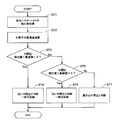
- FIG. 4 is a flowchart showing the flow of controlling the intermediate pressure in the first embodiment.
- the control device 70 the high pressure value in the gas cycle, the optimum value of the intermediate pressure with respect to the low pressure value, and the dead zone ⁇ thereof are stored in advance by various data such as a ph diagram. In the range in which the dead zone ⁇ is added to and subtracted from the optimum value of the intermediate pressure, the value can be set to the same compression power as when the optimum value is set.
- step ST1 the control device 70 acquires the detected values of the low pressure sensor 61, the medium pressure sensor 62, the high pressure sensor 63, and the temperature sensor 64.
- step ST2 the control device 70 calculates the optimum value of the intermediate pressure from the acquired detection values of the low pressure sensor 61, the high pressure sensor 63, and the temperature sensor 64, and various data stored in the storage device.
- step ST3 the control device 70 determines whether or not the detected value of the intermediate pressure in the medium pressure sensor 62 is smaller than the value obtained by subtracting the dead zone ⁇ from the optimum value of the intermediate pressure in step ST2. If the detected value of the intermediate pressure is smaller (step ST3: Yes), the process proceeds to step ST4, and if not (step ST3: No), the process proceeds to step ST5.
- step ST4 the control device 70 determines that the intermediate pressure is low. Then, the control device 70 controls at least one of the low-stage compression unit 52 and the high-stage compression unit 53, and controls the intermediate pressure to be adjusted and boosted.
- step ST5 the control device 70 determines whether or not the detected value of the intermediate pressure in the medium pressure sensor 62 is larger than the value obtained by adding the dead zone ⁇ to the optimum value of the intermediate pressure in step ST2. If the detected value of the intermediate pressure is larger (step ST5: Yes), the process proceeds to step ST6, and if not (step ST5: No), the process proceeds to step ST7.
- step ST6 the control device 70 determines that the intermediate pressure is low. Then, the control device 70 controls at least one of the low-stage compression unit 52 and the high-stage compression unit 53, and controls the intermediate pressure to be adjusted to lower the pressure. In step ST7, it is determined that the control device 70 has an appropriate intermediate pressure. The control of the intermediate pressure is performed at a preset time or at predetermined time intervals.
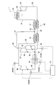
- FIG. 5 is a schematic configuration diagram of the supercritical fluid power generation system according to the second embodiment. As shown in FIG. 5, in the second embodiment, the configurations of the compression device 50 and the radiator 40 are changed from those of the first embodiment.
- the compressor 50 includes a main compressor 56 and a bypass compressor 57.
- the bypass compressor 57 includes a low-stage bypass compression unit 58 and a high-stage bypass compression unit 59, and divides the compression process in the bypass compressor 57.
- the radiator 40 in the second embodiment does not have two lines on the low pressure side and the high pressure side as in the first embodiment, but has one line having the same pressure.
- the inlet of the low-stage bypass compression unit 58 is connected to the outlet in the high-temperature side line of the low-temperature regenerative heat exchanger 32 by a flow path 94.
- the outlet of the low-stage bypass compression unit 58 is connected to the inlet of the radiator 40 by a flow path 95.
- the inlet of the high-stage bypass compression unit 59 is connected to a flow path 96 branched from the flow path 95 between the low-stage bypass compression unit 58 and the radiator 40.
- the outlet of the high-stage bypass compression unit 59 is connected by a flow path 97 that joins the flow path 85 between the low-temperature regeneration heat exchanger 32 and the high-temperature regeneration heat exchanger 31.
- the bypass compressor 57 extracts and compresses supercritical carbon dioxide before flowing into the radiator 40 on the upstream side of the main compressor 56, compresses it, and sends it to the turbine 20 side via the high temperature regenerative heat exchanger 31.
- the inlet of the main compressor 56 is connected to the outlet of the radiator 40 by a flow path 98.
- the outlet of the main compressor 56 is connected to the inlet in the low temperature side line of the low temperature regenerative heat exchanger 32 by a flow path 99.
- the supercritical carbon dioxide is compressed by the low-stage bypass compression unit 58 and then cooled by the radiator 40. After that, the supercritical carbon dioxide cooled by the radiator 40 is compressed by the main compressor 56.
- the low-stage bypass compression unit 58 can form a low-stage compression unit that compresses the supercritical carbon dioxide expanded by the turbine 20, and the low-stage compression unit can be configured by a part of the bypass compressor 57. .. Further, the main compressor 56 can form a high-stage compression unit that compresses supercritical carbon dioxide compressed by the low-stage bypass compression unit 58, which is a low-stage compression unit. Then, the radiator 40 cools the supercritical carbon dioxide flowing from the low-stage bypass compression unit 58 (low-stage compression unit) to the main compressor 56 (high-stage compression unit).
- the low pressure side is in a state before being compressed by the low-stage bypass compression unit 58 of the bypass compressor 57 via the turbine 20. Therefore, the low pressure sensor 61 is provided in the flow path 94 on the inlet side of the low-stage bypass compression unit 58.
- the high pressure side is in the state after passing through the main compressor 56. Therefore, the high pressure sensor 63 is provided in the flow path 99 on the outlet side of the main compressor 56.
- the intermediate pressure between the low pressure side and the high pressure side is in a state between the low stage bypass compression unit 58 and the main compressor 56. Therefore, the medium pressure sensor 62 is provided in the flow path 98 between the radiator 40 and the main compressor 56.
- the control device 70 controls the low-stage bypass compressor 58 and the main compressor 56 based on the detection results of the low-pressure sensor 61, the medium-pressure sensor 62, the high-pressure sensor 63, and the temperature sensor 64.
- the intermediate pressure of supercritical carbon dioxide flowing through the radiator 40 can be adjusted by controlling the low-stage bypass compression unit 58 and the main compressor 56 by the control device 70. Therefore, also in the second embodiment, by adjusting the intermediate pressure as in the first embodiment, the sum of the compression powers of the low-stage bypass compression unit 58 and the main compressor 56 can be suppressed, and the radiator can be used as a radiator. Even if the temperature of 40 approaches the critical temperature, the rapid increase in compression power can be suppressed.
- the regenerative heat exchanger 30 is provided with the two-stage regenerated heat exchangers 31 and 32, but the present invention is not limited to this, and one of them may be omitted, or further. Regenerative heat exchangers may be added. Further, the supercritical fluid power generation system 1 may be configured without the regenerated heat exchanger 30 itself. However, since the supercritical fluid power generation system 1 has the regenerated heat exchanger 30, it is advantageous in that the supercritical carbon dioxide introduced into the heat receiving equipment 10 can be efficiently heated.
- one radiator 40 has a high-voltage side and a low-voltage side line, but separate radiators 40 may be provided on the high-voltage side and the low-voltage side.
- the low pressure sensor 61 is installed at the position upstream of the low-stage compression unit 52 and downstream of the turbine 20 because the pressure change on the low-voltage side is small in the ph diagram of FIG. If it is on the side, it may be a location other than the flow path 88. Further, the installation position of the low pressure sensor 61 in the second embodiment may be a location other than the flow path 94 as long as it is on the upstream side of the low-stage bypass compression unit 58 and on the downstream side of the turbine 20.
- the installation position of the medium pressure sensor 62 is a flow path on the downstream side of the low-stage compression portion 52 because the pressure change of the intermediate pressure is small in the ph diagram of FIG. It may be 89. Further, the installation position of the low-voltage sensor 61 in the second embodiment may be the flow path 95 on the downstream side of the low-stage bypass compression unit 58.
- the supercritical fluid is not limited to supercritical carbon dioxide as long as the supercritical fluid power generation system 1 can be operated as in each of the above embodiments.
Landscapes
- Engineering & Computer Science (AREA)
- Chemical & Material Sciences (AREA)
- Combustion & Propulsion (AREA)
- Mechanical Engineering (AREA)
- General Engineering & Computer Science (AREA)
- Engine Equipment That Uses Special Cycles (AREA)
Abstract
放熱器の温度が臨界温度に近くなる運転条件において、圧縮装置における圧縮動力の急増を抑制することができる超臨界流体発電システムを提供すること。超臨界流体発電システム(1)は、受熱設備(10)、タービン(20)、放熱器(40)及び圧縮装置(50)を流路(81~92)で接続し、超臨界二酸化炭素を作動流体とした閉サイクルを用いる。圧縮装置は、タービンで膨張された超臨界二酸化炭素を圧縮する低段圧縮部(52)と、低段圧縮部で圧縮した超臨界二酸化炭素を圧縮する高段圧縮部(53)とを備えている。放熱器は、低段圧縮部から高段圧縮部を流れる超臨界流体を冷却する。
Description
本発明は、超臨界流体を作動流体として用いる超臨界流体発電システムに関する。
火力発電をはじめとする従来の蒸気発電システムに対し、高効率且つコンパクト化が期待される超臨界二酸化炭素発電サイクル(特許文献1参照)が盛んに研究されている。かかる研究において、様々な構成のサイクルが比較され分流再圧サイクルが高効率であるとする研究成果がある。
しかしながら、超臨界流体は臨界点近傍で物性値が急変する特徴を有しており、例えば超臨界二酸化炭素の場合、臨界温度の約31℃近傍でp-h線図の等温線勾配が顕著に小さくなる(図2参照)。このため、超臨界二酸化炭素サイクルでは、外気温度や圧力等の放熱器での運転条件によって圧縮機に流入する超臨界二酸化炭素の比エンタルピが大きく変化し、圧縮機における動力急増を招く、という問題がある。
本発明は、かかる点に鑑みてなされたものであり、放熱器の温度が臨界温度に近くなる運転条件において、圧縮装置における圧縮動力の急増を抑制することができる超臨界流体発電システムを提供することを目的の一つとする。
本発明における一態様の超臨界流体発電システムは、受熱設備、タービン、放熱器及び圧縮装置を流路で接続し、超臨界流体を作動流体とする閉サイクルを用いた超臨界流体発電システムであって、前記圧縮装置は、前記タービンで膨張された超臨界流体を圧縮する低段圧縮部と、該低段圧縮部で圧縮した超臨界流体を圧縮する高段圧縮部とを備え、前記放熱器は、前記低段圧縮部から前記高段圧縮部を流れる超臨界流体を冷却することを特徴とする。
本発明によれば、圧縮装置での圧縮を低段圧縮部と高段圧縮部とで分割し、それらの間の超臨界流体を放熱器で冷却して該超臨界流体の圧力(中間圧)を調整することができる。これにより、外気温度が高い等により放熱器の放熱性能が低下しても、超臨界流体を1回だけ圧縮する従来構造の圧縮動力に対し、低段圧縮部及び高段圧縮部の圧縮動力の和を削減することができる。これにより、放熱器の温度が臨界温度に近くなる運転条件においても、圧縮動力の急増を抑制することができる。
以下、本発明の一実施の形態に係る超臨界流体発電システムについて、添付の図面を参照しながら詳細に説明する。なお、本発明に係る超臨界流体発電システムについては、以下の実施の形態に限定されるものではなく、その趣旨の範囲内で種々変形して実施することができる。
[第1の実施の形態]
図1は、第1の実施の形態に係る超臨界流体発電システムの概略構成図である。図1に示すように、超臨界流体発電システム1は、受熱設備10、タービン20と、再生熱交換器30と、放熱器40と、圧縮装置50と、検出装置60と、制御装置70とを備えている。超臨界流体発電システム1は、上記各装置等を配管等からなる流路81~92で接続している。各流路81~92の接続位置については後述する。超臨界流体発電システム1は、作動流体を超臨界流体、具体的には、超臨界二酸化炭素(CO2)とする閉サイクルを用いている。
図1は、第1の実施の形態に係る超臨界流体発電システムの概略構成図である。図1に示すように、超臨界流体発電システム1は、受熱設備10、タービン20と、再生熱交換器30と、放熱器40と、圧縮装置50と、検出装置60と、制御装置70とを備えている。超臨界流体発電システム1は、上記各装置等を配管等からなる流路81~92で接続している。各流路81~92の接続位置については後述する。超臨界流体発電システム1は、作動流体を超臨界流体、具体的には、超臨界二酸化炭素(CO2)とする閉サイクルを用いている。
受熱設備10は、熱源からの熱を受けて超臨界二酸化炭素を加熱(昇温)する。受熱設備10の入口は、再生熱交換器30の出口と流路81によって接続され、受熱設備10の出口は、タービン20の入口と流路82によって接続される。受熱設備10の熱源は、火力や原子力の他、地熱や太陽熱、バイオマス等の周知の各種熱源を用いることができる。
タービン20は、流路81を通じて受熱設備10で加熱された超臨界二酸化炭素が流入し、通過する間に超臨界二酸化炭素を膨張させて機械的動力を生成する。タービン20は、例えば、駆動軸を回転して発電機(何れも不図示)を駆動し、該発電機にて発電を行うことができる。タービン20の出口は、再生熱交換器30の入口と流路83によって接続される。
再生熱交換器30は、タービン20を経て放熱器40側へ流出する高温の超臨界二酸化炭素と、圧縮装置50を経て受熱設備10側へ流出する低温の超臨界二酸化炭素との間で熱交換する。再生熱交換器30は、高温再生熱交換器31と、低温再生熱交換器32とを備えて2段階で熱交換を行っている。
高温再生熱交換器31及び低温再生熱交換器32は、高温側及び低温側の2つのラインをそれぞれ有している。高温再生熱交換器31の高温側ラインにおける入口は、タービン20の出口と流路83によって接続される。高温再生熱交換器31の高温側ラインにおける出口は、低温再生熱交換器32の高温側ラインにおける入口と流路84によって接続される。高温再生熱交換器31の低温側ラインにおける入口は、低温再生熱交換器32の低温側ラインにおける出口と流路85によって接続される。高温再生熱交換器31の低温側ラインにおける出口は、受熱設備10の入口と流路81によって接続される。
低温再生熱交換器32の高温側ラインにおける出口は、放熱器40の入口と流路86によって接続される。低温再生熱交換器32の低温側ラインにおける入口は、圧縮装置50の後述する高段圧縮部53の出口と流路87によって接続される。低温再生熱交換器32の低温側のラインにおける出口は、高温再生熱交換器31の低温側ラインの入口と流路85によって接続される。
放熱器40は、外気を介して内部を流れる超臨界二酸化炭素から熱を除去して冷却する。放熱器40は、低圧側及び高圧側の2つのラインを有している。放熱器40の低圧側ラインにおける入口は、低温再生熱交換器32の高温側ラインにおける出口と流路86によって接続される。
圧縮装置50は、タービン20で膨張された超臨界二酸化炭素が流入し、通過する間に該超臨界二酸化炭素を所定の駆動力を介して圧縮する。圧縮装置50は、主圧縮機51と、バイパス圧縮機54とを備えている。主圧縮機51は、低段圧縮部52と、高段圧縮部53とを備え、主圧縮機51での圧縮工程を分割している。
低段圧縮部52の入口は、放熱器40の低圧側ラインにおける出口と流路88によって接続される。低段圧縮部52の出口は、放熱器40の高圧側ラインにおける入口と流路89によって接続される。高段圧縮部53の入口は、放熱器40の高圧側ラインにおける出口と流路90によって接続される。高段圧縮部53の出口は、低温再生熱交換器32の低温側ラインにおける入口と流路87によって接続される。
低段圧縮部52は、タービン20で膨張されてから再生熱交換器30及び放熱器40を経て冷却された超臨界二酸化炭素を圧縮する。言い換えると、低段圧縮部52より上流側の超臨界二酸化炭素が再生熱交換器30及び放熱器40で冷却される。高段圧縮部53は、低段圧縮部52で圧縮されてから放熱器40で冷却された超臨界二酸化炭素を圧縮する。よって、低段圧縮部52から高段圧縮部53を流れる超臨界二酸化炭素も放熱器40で冷却される。
バイパス圧縮機54の入口は、低温再生熱交換器32と放熱器40との間の流路86から分岐される流路91に接続される。バイパス圧縮機54の出口は、低温再生熱交換器32と高温再生熱交換器31との間の流路85と合流する流路92に接続される。バイパス圧縮機54は、主圧縮機51より上流側となる低温再生熱交換器32から放熱器40に流れる超臨界二酸化炭素を抽気して圧縮し、高温再生熱交換器31を経てタービン20側に送出する。
検出装置60は、低圧センサ61と、中圧センサ62と、高圧センサ63と、温度センサ64とを備えている。低圧センサ61は、低段圧縮部52の上流側における超臨界二酸化炭素の圧力を検出し、本実施の形態では、放熱器40と低段圧縮部52との間の流路88を流れる超臨界二酸化炭素の圧力を検出する。
中圧センサ62は、低段圧縮部52と高段圧縮部53との間の超臨界二酸化炭素の中間圧(圧力)を検出し、本実施の形態では、放熱器40と高段圧縮部53との間の流路90を流れる超臨界二酸化炭素の中間圧を検出する。
高圧センサ63は、高段圧縮部53の下流側における超臨界二酸化炭素の圧力を検出し、本実施の形態では、高段圧縮部53と低温再生熱交換器32との間の流路87を流れる超臨界二酸化炭素の圧力を検出する。
温度センサ64は、放熱器40での放熱温度を検出する。放熱器40では外気を用いて冷却されるので、温度センサ64の検出結果は外気温より高温となる。
制御装置70は、中央処理装置(CPU)や、RAM、ROM等の記憶装置を含むコンピュータ等によって構成され、超臨界流体発電システム1全体を制御する。制御装置70は、記憶装置に記憶されるアプリケーションや演算式、テーブル、データ等と、低圧センサ61、中圧センサ62、高圧センサ63及び温度センサ64の検出結果とに基づき、低段圧縮部52及び高段圧縮部53を制御する。かかる制御としては、各圧縮部52、53の回転数制御、それらを多段圧縮とした場合に抽気個所を変更する制御、圧縮機静翼の迎え角制御等の何れか又はそれらを組合せとすることを例示できる。制御装置70による低段圧縮部52及び高段圧縮部53の制御によって、放熱器40の低圧側ラインを流れる超臨界二酸化炭素の中間圧を調整することができる。
ここで、超臨界二酸化炭素サイクルでの運転について検討する。図2は、比較例の超臨界二酸化炭素サイクルのp-h線図である。図2のp-h線図は、比較例として、公知の超臨界二酸化炭素サイクルの一例を挙げたものである。状態A→状態Bにて、超臨界二酸化炭素がタービンで膨張されて圧力が低下する。状態B→状態Ca又は状態Cbにて、超臨界二酸化炭素が放熱器等で冷却され、略等圧又は若干の圧力低下の条件下で比エンタルピが低下する。かかる比エンタルピの低下は放熱器の放熱温度に達するまで、言い換えると、p-h線図の等温線(細い実線で表す)に交差する位置まで進行する。よって、放熱温度が35℃の場合の状態Cbの方が、放熱温度が45℃の場合の状態Caより、比エンタルピが低下する。
状態Ca又は状態Cb→状態Da又は状態Dbにて、圧縮(昇圧)工程として超臨界二酸化炭素が圧縮機で圧縮されて圧力が高くなる。このとき、p-h線図での勾配は、理想的には等エントロピ線(二点鎖線で表す)と略平行となる。等エントロピ線は、比エンタルピが低くなると急勾配に、比エンタルピが高くなると緩勾配になる。状態Caと状態Cbは略同圧であり、状態Daと状態Dbは略同圧であるので、p-h線図の勾配の違いにより、状態Cb→状態Dbに比べて状態Ca→状態Daの方が比エンタルピの増加量が大きくなる。比エンタルピの増加量は圧縮機の圧縮動力の増加量となり、放熱温度が35℃の場合(状態Cb→状態Db)の圧縮動力Pbとし、放熱温度が45℃の場合(状態Ca→状態Da)の圧縮動力Paとすると、圧縮動力Pbより圧縮動力Paが増大する。
図2のp-h線図において、圧縮動力Pbを100%とした場合、圧縮動力Paは112%となった。従って、放熱器の放熱温度が35℃から45℃に上昇することで、圧縮動力が12%増加してしまった。そこで、第1の実施の形態においては、かかる圧縮動力の増加抑制を以下に述べるように実現している。
図3は、第1の実施の形態の超臨界二酸化炭素サイクルのp-h線図である。図3のp-h線図における第1の実施の形態の超臨界二酸化炭素サイクルでは、比較例と比べるために放熱器40の放熱温度を45℃とし、比較例に対し超臨界二酸化炭素の圧縮工程を変えている。それ以外は、比較例と第1の実施の形態とで同条件となるので、状態A→状態B→状態Caでは上記比較例と同様に超臨界二酸化炭素が膨張及び冷却される。
第1の実施の形態において、状態Caは、再生熱交換器30及び放熱器40の低圧側ラインの下流側、且つ、低段圧縮部52の上流側(低圧センサ61の位置)における超臨界二酸化炭素の状態とされる。状態Ca→状態Eにて、低段圧縮部52で超臨界二酸化炭素が圧縮(昇圧)され、また、昇温される。状態Eは、低段圧縮部52の下流側、且つ、放熱器40の高圧側ラインの上流側の流路89における超臨界二酸化炭素の状態とされる。状態Ca→状態Eにおいても、p-h線図での勾配は等エントロピ線と略平行となり、この際の低段圧縮部52の動力を圧縮動力Pw1とする。
状態Fは、放熱器40の高圧側ラインの下流側、且つ、高段圧縮部53の上流側(中圧センサ62の位置)における超臨界二酸化炭素の状態とされる。状態E→状態Fにて、超臨界二酸化炭素が放熱器40の高圧側ラインを通過し、放熱器40の放熱温度45℃になるまで冷却される。よって、p-h線図の状態E→状態Fでは、超臨界二酸化炭素の状態が略同圧にて45℃の等温線に交差する位置まで進行する。状態E→状態Fにおける超臨界二酸化炭素の圧力が中間圧とされる。
状態Dcは、状態Db(図2参照)と略同圧であり、高段圧縮部53の下流側(高圧センサ63の位置)における超臨界二酸化炭素の状態とされる。状態F→状態Dcにて、高段圧縮部53で超臨界二酸化炭素が圧縮(昇圧)される。状態F→状態Dcにおいても、p-h線図での勾配は等エントロピ線と略平行となり、この際の高段圧縮部53の動力を圧縮動力Pw2とする。よって、本実施の形態では、圧縮工程全体での圧縮動力Pwは、圧縮動力Pw1と圧縮動力Pw2の和となり、圧縮動力Pw1及び圧縮動力Pw2は状態E及び状態Fにおける中間圧によって変化する。従って、中間圧を調整することによって、比較例の放熱温度が45℃の圧縮動力Paに比べて圧縮動力Pwを小さくすることができる。
図3のp-h線図に示すように、等エントロピ線の勾配は比エンタルピが低くなるほど急になり、圧縮動力を低減する比エンタルピの低減効果を得ることができる。また、放熱温度における等温線の比エンタルピは高圧になるほど低くなる。よって、状態E→状態Fにおける超臨界二酸化炭素の中間圧が低くなると、比エンタルピの低減効果が小さくなり、状態F→状態Dcでの圧縮動力Pw2の低減効果も小さくなる。一方、状態E→状態Fにおける超臨界二酸化炭素の中間圧が高くなると、状態F→状態Dcでの圧縮動力Pw2の低減効果は得られるが、状態Ca→状態Eでの圧縮動力Pw1を十分に削減できなくなる。従って、p-h線図にて、状態Caの圧力と状態Dcの圧力との間にて中間圧に対する運転中の放熱温度における各圧縮動力Pw1、Pw2の関係を求め、それらの和となる圧縮動力Pwを演算することで、最小となる圧縮動力Pw及びその際の最適な中間圧を求めることができる。
図3のp-h線図にて、最適な中間圧を設定した場合の圧縮動力Pwは、比較例の放熱温度が35℃の圧縮動力Pbを100%とした場合に比べ、103%にすることができた。比較例の放熱温度が45℃の場合の圧縮動力Paは112%だったので、本実施の形態の方が9%削減できた。これにより、放熱器40の放熱温度が35℃から45℃となる放熱性能の低下が発生しても、比較例に比べて圧縮動力Pwを削減することが可能となる。この結果、放熱器40の温度が超臨界二酸化炭素の臨界温度(31℃)に近くなる運転条件において、外気温等の変化により圧縮動力Pwの急増を抑制することができる。
続いて、本実施の形態における制御装置70による中間圧の制御について、図4を参照して説明する。図4は、第1の実施の形態における中間圧の制御の流れを示すフローチャートである。なお、制御装置70には、p-h線図等の各種データによって、ガスサイクルでの高圧値、低圧値に対する中間圧の最適値及びその不感帯δが予め記憶される。不感帯δを中間圧の最適値に加算及び減算した範囲において、該最適値に設定した場合と同等の圧縮動力に設定できる値とされる。
図4のフローチャートにおいて、ステップST1では、制御装置70が、低圧センサ61、中圧センサ62、高圧センサ63及び温度センサ64の各検出値を取得する。ステップST2では、制御装置70が、取得した低圧センサ61、高圧センサ63及び温度センサ64の各検出値と、記憶装置に記憶される各種データとから中間圧の最適値を演算する。
ステップST3では、制御装置70が、ステップST2の中間圧の最適値に不感帯δを減算した値に対し、中圧センサ62における中間圧の検出値の方が小さいか否かを判定する。かかる中間圧の検出値の方が小さいときは(ステップST3:Yes)、ステップST4に進み、そうでないときは(ステップST3:No)、ステップST5に進む。
ステップST4では、制御装置70が、中間圧が低いと判断する。そして、制御装置70が、低段圧縮部52及び高段圧縮部53の少なくとも一方を制御し、中間圧を調整して昇圧する制御を行う。
ステップST5では、制御装置70が、ステップST2の中間圧の最適値に不感帯δを加算した値に対し、中圧センサ62における中間圧の検出値の方が大きいか否かを判定する。かかる中間圧の検出値の方が大きいときは(ステップST5:Yes)、ステップST6に進み、そうでないときは(ステップST5:No)、ステップST7に進む。
ステップST6では、制御装置70が、中間圧が低いと判断する。そして、制御装置70が、低段圧縮部52及び高段圧縮部53の少なくとも一方を制御し、中間圧を調整して降圧する制御を行う。ステップST7では、制御装置70が適正な中間圧であると判断する。かかる中間圧の制御は、予め設定した時刻や、所定時間毎に実施される。
[第2の実施の形態]
次に、本発明の第2の実施の形態について説明する。なお、以下の説明において、第1の実施の形態と同一若しくは同等の構成部分については同一符号を用いる場合があり、説明を省略若しくは簡略にする場合がある。図5は、第2の実施の形態に係る超臨界流体発電システムの概略構成図である。図5に示すように、第2の実施の形態では、第1の実施の形態に対し、圧縮装置50及び放熱器40の構成を変更している。
次に、本発明の第2の実施の形態について説明する。なお、以下の説明において、第1の実施の形態と同一若しくは同等の構成部分については同一符号を用いる場合があり、説明を省略若しくは簡略にする場合がある。図5は、第2の実施の形態に係る超臨界流体発電システムの概略構成図である。図5に示すように、第2の実施の形態では、第1の実施の形態に対し、圧縮装置50及び放熱器40の構成を変更している。
第2の実施の形態において、圧縮装置50は、主圧縮機56と、バイパス圧縮機57とを備えている。バイパス圧縮機57は、低段バイパス圧縮部58と、高段バイパス圧縮部59とを備え、バイパス圧縮機57での圧縮工程を分割している。また、第2の実施の形態における放熱器40は、第1の実施の形態のように低圧側及び高圧側の2つのラインを有するものでなく、同圧の1つのラインを有する。
低段バイパス圧縮部58の入口は、低温再生熱交換器32の高温側ラインにおける出口と流路94によって接続される。低段バイパス圧縮部58の出口は、放熱器40の入口と流路95によって接続される。高段バイパス圧縮部59の入口は、低段バイパス圧縮部58と放熱器40との間の流路95から分岐される流路96に接続される。高段バイパス圧縮部59の出口は、低温再生熱交換器32と高温再生熱交換器31との間の流路85と合流する流路97によって接続される。バイパス圧縮機57は、主圧縮機56より上流側となる放熱器40に流れる前の超臨界二酸化炭素を抽気して圧縮し、高温再生熱交換器31を経てタービン20側に送出する。
主圧縮機56の入口は、放熱器40の出口と流路98によって接続される。主圧縮機56の出口は、低温再生熱交換器32の低温側ラインにおける入口と流路99によって接続される。
第2の実施の形態のガスサイクルでは、超臨界二酸化炭素が低段バイパス圧縮部58で圧縮された後、放熱器40で冷却される。その後、放熱器40で冷却された超臨界二酸化炭素が主圧縮機56で圧縮される。
従って、低段バイパス圧縮部58によって、タービン20で膨張された超臨界二酸化炭素を圧縮する低段圧縮部を構成でき、該低段圧縮部をバイパス圧縮機57の一部によって構成することができる。また、主圧縮機56によって、低段圧縮部となる低段バイパス圧縮部58によって圧縮した超臨界二酸化炭素を圧縮する高段圧縮部を構成することができる。そして、放熱器40は、低段バイパス圧縮部58(低段圧縮部)から主圧縮機56(高段圧縮部)を流れる超臨界二酸化炭素を冷却することとなる。
第2の実施の形態のガスサイクルにおいて、低圧側は、タービン20を経てバイパス圧縮機57の低段バイパス圧縮部58で圧縮される前の状態となる。よって、低圧センサ61は、低段バイパス圧縮部58の入口側の流路94に設けられる。
また、第2の実施の形態のガスサイクルにおいて、高圧側は、主圧縮機56を経た後の状態となる。よって、高圧センサ63は、主圧縮機56の出口側の流路99に設けられる。
更に、第2の実施の形態のガスサイクルにおいて、低圧側と高圧側との間の中間圧は、低段バイパス圧縮部58と主圧縮機56と間の状態となる。よって、中圧センサ62は、放熱器40と主圧縮機56との間の流路98に設けられる。
制御装置70は、低圧センサ61、中圧センサ62、高圧センサ63及び温度センサ64の検出結果に基づき、低段バイパス圧縮部58及び主圧縮機56を制御する。制御装置70による低段バイパス圧縮部58及び主圧縮機56の制御によって、放熱器40を流れる超臨界二酸化炭素の中間圧を調整することができる。よって、第2の実施の形態においても、第1の実施の形態と同様に中間圧を調整することで、低段バイパス圧縮部58及び主圧縮機56の圧縮動力の和を抑制でき、放熱器40の温度が臨界温度に近くなっても、圧縮動力の急増を抑制することができる。
本発明の実施の形態は上記の各実施の形態に限定されるものではなく、本発明の技術的思想の趣旨を逸脱しない範囲において様々に変更、置換、変形されてもよい。さらには、技術の進歩又は派生する別技術によって、本発明の技術的思想を別の仕方で実現することができれば、その方法を用いて実施されてもよい。したがって、特許請求の範囲は、本発明の技術的思想の範囲内に含まれ得る全ての実施態様をカバーしている。
上記各実施の形態では、再生熱交換器30が2段階の再生熱交換器31、32を備えた構成としたが、これに限られるものでなく、何れか一方を省略した構成としたり、更に再生熱交換器を増設したりしてもよい。また、超臨界流体発電システム1において、再生熱交換器30自体がない構成としてもよい。但し、超臨界流体発電システム1が再生熱交換器30を有することで、受熱設備10に導入される超臨界二酸化炭素を効率良く昇温できる点で有利となる。
また、第1の実施の形態では、1台の放熱器40にて高圧側及び低圧側のラインを有する構成としたが、高圧側及び低圧側にて別々の放熱器40を設けてもよい。
また、第1の実施の形態において、低圧センサ61の設置位置は、図3のp-h線図にて低圧側の圧力変化が小さいので、低段圧縮部52より上流側でタービン20より下流側であれば流路88以外の箇所としてもよい。更に、第2の実施の形態における低圧センサ61の設置位置は、低段バイパス圧縮部58より上流側でタービン20より下流側であれば流路94以外の箇所としてもよい。
また、第1の実施の形態において、中圧センサ62の設置位置は、図3のp-h線図にて中間圧の圧力変化が小さいので、低段圧縮部52より下流側となる流路89としてもよい。更に、第2の実施の形態における低圧センサ61の設置位置は、低段バイパス圧縮部58より下流側となる流路95としてもよい。
また、超臨界流体は、上記各実施の形態と同様に超臨界流体発電システム1を運転できれば、超臨界二酸化炭素に限定されるものでない。
Claims (7)
- 受熱設備、タービン、放熱器及び圧縮装置を流路で接続し、超臨界流体を作動流体とする閉サイクルを用いた超臨界流体発電システムであって、
前記圧縮装置は、前記タービンで膨張された超臨界流体を圧縮する低段圧縮部と、該低段圧縮部で圧縮した超臨界流体を圧縮する高段圧縮部とを備え、
前記放熱器は、前記低段圧縮部から前記高段圧縮部を流れる超臨界流体を冷却することを特徴とする超臨界流体発電システム。 - 前記圧縮装置は、主圧縮機と、該主圧縮機より上流側の超臨界流体を抽気して圧縮し、前記タービン側に送出するバイパス圧縮機とを備え、
前記低段圧縮部及び前記高段圧縮部によって前記主圧縮機が構成されることを特徴とする請求項1に記載の超臨界流体発電システム。 - 前記放熱器は、前記低段圧縮部より上流側の超臨界流体も冷却することを特徴とする請求項1または請求項2に記載の超臨界流体発電システム。
- 前記圧縮装置は、主圧縮機と、該主圧縮機より上流側の超臨界流体を抽気して圧縮し、前記タービン側に送出するバイパス圧縮機とを備え、
前記低段圧縮部によって前記バイパス圧縮機の少なくとも一部が構成され、
前記高段圧縮部によって前記主圧縮機が構成されることを特徴とする請求項1に記載の超臨界流体発電システム。 - 前記タービンと前記低段圧縮部との間に再生熱交換器を備え、
該再生熱交換器は、前記タービンを経た超臨界流体と、前記圧縮装置を経た超臨界流体とで熱交換することを特徴とする請求項1ないし請求項4のいずれかに記載の超臨界流体発電システム。 - 前記低段圧縮部の上流側における超臨界流体の圧力を検出する低圧センサと、
前記低段圧縮部と前記高段圧縮部との間の超臨界流体の中間圧を検出する中圧センサと、
前記高段圧縮部の下流側における超臨界流体の圧力を検出する高圧センサと、
前記放熱器での放熱温度を検出する温度センサと、
前記各センサの検出結果に基づき、前記低段圧縮部及び前記高段圧縮部の制御を介して前記中間圧を調整する制御装置と、を備えていることを特徴とする請求項1ないし請求項5のいずれかに記載の超臨界流体発電システム。 - 超臨界流体は超臨界二酸化炭素であることを特徴とする請求項1ないし請求項6のいずれかに記載の超臨界流体発電システム。
Priority Applications (1)
| Application Number | Priority Date | Filing Date | Title |
|---|---|---|---|
| PCT/JP2020/010103 WO2021181483A1 (ja) | 2020-03-09 | 2020-03-09 | 超臨界流体発電システム |
Applications Claiming Priority (1)
| Application Number | Priority Date | Filing Date | Title |
|---|---|---|---|
| PCT/JP2020/010103 WO2021181483A1 (ja) | 2020-03-09 | 2020-03-09 | 超臨界流体発電システム |
Publications (1)
| Publication Number | Publication Date |
|---|---|
| WO2021181483A1 true WO2021181483A1 (ja) | 2021-09-16 |
Family
ID=77671283
Family Applications (1)
| Application Number | Title | Priority Date | Filing Date |
|---|---|---|---|
| PCT/JP2020/010103 Ceased WO2021181483A1 (ja) | 2020-03-09 | 2020-03-09 | 超臨界流体発電システム |
Country Status (1)
| Country | Link |
|---|---|
| WO (1) | WO2021181483A1 (ja) |
Cited By (4)
| Publication number | Priority date | Publication date | Assignee | Title |
|---|---|---|---|---|
| US20230213246A1 (en) * | 2022-01-02 | 2023-07-06 | AirMyne, Inc. | Using Carbon Dioxide From A Direct Air Capture System As A Low Global Warming Car And Industrial Refrigerant |
| CN119412186A (zh) * | 2024-10-30 | 2025-02-11 | 中国科学院工程热物理研究所 | 一种绝热超临界压缩二氧化碳储能系统 |
| US12599867B2 (en) | 2022-01-02 | 2026-04-14 | AirMyne, Inc. | Fully automated direct air capture carbon dioxide processing system |
| US12616934B2 (en) | 2024-05-21 | 2026-05-05 | AirMyne, Inc. | Fully automated direct air capture carbon dioxide processing system |
Citations (2)
| Publication number | Priority date | Publication date | Assignee | Title |
|---|---|---|---|---|
| JP2012145092A (ja) * | 2011-01-12 | 2012-08-02 | Shintaro Ishiyama | 超臨界二酸化炭素(co2)圧縮用遠心ブロア(コンプレッサー)、超臨界co2ガスタービンならびに発電機を備えた超臨界co2ガスタービン発電技術 |
| CN108612573A (zh) * | 2018-07-05 | 2018-10-02 | 华北电力大学 | 一种超临界二氧化碳布雷顿循环发电系统 |
-
2020
- 2020-03-09 WO PCT/JP2020/010103 patent/WO2021181483A1/ja not_active Ceased
Patent Citations (2)
| Publication number | Priority date | Publication date | Assignee | Title |
|---|---|---|---|---|
| JP2012145092A (ja) * | 2011-01-12 | 2012-08-02 | Shintaro Ishiyama | 超臨界二酸化炭素(co2)圧縮用遠心ブロア(コンプレッサー)、超臨界co2ガスタービンならびに発電機を備えた超臨界co2ガスタービン発電技術 |
| CN108612573A (zh) * | 2018-07-05 | 2018-10-02 | 华北电力大学 | 一种超临界二氧化碳布雷顿循环发电系统 |
Cited By (4)
| Publication number | Priority date | Publication date | Assignee | Title |
|---|---|---|---|---|
| US20230213246A1 (en) * | 2022-01-02 | 2023-07-06 | AirMyne, Inc. | Using Carbon Dioxide From A Direct Air Capture System As A Low Global Warming Car And Industrial Refrigerant |
| US12599867B2 (en) | 2022-01-02 | 2026-04-14 | AirMyne, Inc. | Fully automated direct air capture carbon dioxide processing system |
| US12616934B2 (en) | 2024-05-21 | 2026-05-05 | AirMyne, Inc. | Fully automated direct air capture carbon dioxide processing system |
| CN119412186A (zh) * | 2024-10-30 | 2025-02-11 | 中国科学院工程热物理研究所 | 一种绝热超临界压缩二氧化碳储能系统 |
Similar Documents
| Publication | Publication Date | Title |
|---|---|---|
| RU2719413C2 (ru) | Системы с замкнутым регенеративным термодинамическим циклом выработки электроэнергии и способы их работы | |
| CA2899163C (en) | Process for controlling a power turbine throttle valve during a supercritical carbon dioxide rankine cycle | |
| EP2964911B1 (en) | Heat engine systems with high net power supercritical carbon dioxide circuits | |
| US10358975B2 (en) | Compressed air energy storage and power generation device | |
| CN107060921B (zh) | 液化空气储能系统的发电装置及方法 | |
| JP6571491B2 (ja) | ヒートポンプ | |
| US20140102098A1 (en) | Bypass and throttle valves for a supercritical working fluid circuit | |
| US20100170218A1 (en) | Method for expanding compressor discharge bleed air | |
| US20140208750A1 (en) | Methods for reducing wear on components of a heat engine system at startup | |
| EP2917506B1 (en) | A turboexpander and driven turbomachine system | |
| WO2021181483A1 (ja) | 超臨界流体発電システム | |
| JP2015203417A (ja) | ランキンサイクルに従って作動する閉ループを制御する装置およびそれを使用する方法 | |
| JP6793616B2 (ja) | 圧縮空気貯蔵発電装置及び圧縮空気貯蔵発電方法 | |
| KR101752230B1 (ko) | 초임계 이산화탄소 발전 시스템 및 열침원 온도에 따른 초임계 이산화탄소 발전 시스템 운전 방법 | |
| CN205297661U (zh) | 一种带回热器的余热发电系统 | |
| CN115435366B (zh) | 火电机组供热系统及方法 | |
| JP2009103423A (ja) | 水蒸気発生型ヒートポンプ装置 | |
| JP4794254B2 (ja) | 蒸気タービンプラントおよびその運転方法 | |
| JP6564710B2 (ja) | 圧縮機システム | |
| JP5660836B2 (ja) | 蒸気圧縮式ヒートポンプ | |
| JP4415189B2 (ja) | 火力発電プラント | |
| WO2021181663A1 (ja) | 超臨界流体発電システム | |
| JP5877765B2 (ja) | 複合動力機器及び複合動力機器の運転方法 | |
| KR20190007301A (ko) | 스팀의 생성과 발전이 연계된 엔진 시스템 | |
| JP7553341B2 (ja) | ランキンサイクル装置およびその運転方法 |
Legal Events
| Date | Code | Title | Description |
|---|---|---|---|
| 121 | Ep: the epo has been informed by wipo that ep was designated in this application |
Ref document number: 20924199 Country of ref document: EP Kind code of ref document: A1 |
|
| NENP | Non-entry into the national phase |
Ref country code: DE |
|
| NENP | Non-entry into the national phase |
Ref country code: JP |
|
| 122 | Ep: pct application non-entry in european phase |
Ref document number: 20924199 Country of ref document: EP Kind code of ref document: A1 |