WO2021181476A1 - 輸液バッグ加圧容器、輸液バッグ加圧装置 - Google Patents
輸液バッグ加圧容器、輸液バッグ加圧装置 Download PDFInfo
- Publication number
- WO2021181476A1 WO2021181476A1 PCT/JP2020/010088 JP2020010088W WO2021181476A1 WO 2021181476 A1 WO2021181476 A1 WO 2021181476A1 JP 2020010088 W JP2020010088 W JP 2020010088W WO 2021181476 A1 WO2021181476 A1 WO 2021181476A1
- Authority
- WO
- WIPO (PCT)
- Prior art keywords
- infusion bag
- pressurizing
- container
- pressure
- hole
- Prior art date
- Legal status (The legal status is an assumption and is not a legal conclusion. Google has not performed a legal analysis and makes no representation as to the accuracy of the status listed.)
- Ceased
Links
Images





Classifications
-
- A—HUMAN NECESSITIES
- A61—MEDICAL OR VETERINARY SCIENCE; HYGIENE
- A61M—DEVICES FOR INTRODUCING MEDIA INTO, OR ONTO, THE BODY; DEVICES FOR TRANSDUCING BODY MEDIA OR FOR TAKING MEDIA FROM THE BODY; DEVICES FOR PRODUCING OR ENDING SLEEP OR STUPOR
- A61M5/00—Devices for bringing media into the body in a subcutaneous, intra-vascular or intramuscular way; Accessories therefor, e.g. filling or cleaning devices, arm-rests
- A61M5/14—Infusion devices, e.g. infusing by gravity; Blood infusion; Accessories therefor
- A61M5/142—Pressure infusion, e.g. using pumps
- A61M5/145—Pressure infusion, e.g. using pumps using pressurised reservoirs, e.g. pressurised by means of pistons
- A61M5/148—Pressure infusion, e.g. using pumps using pressurised reservoirs, e.g. pressurised by means of pistons flexible, e.g. independent bags
Definitions
- the present invention relates to an infusion bag pressurizing container and an infusion bag pressurizing device that can pressurize and send out the internal liquid while accommodating an infusion bag such as an infusion bag.
- This portable drip device has a bellows (6) built in a pressure cylinder (1), and the bellows (6) is driven by the force of a hoisting device (35) using a weight (10) or a spiral spring as a load applying means. Shrinks and increases internal pressure. This pressure is introduced into the closed container (2) or the inflatable bag (23), and the infusion bag (11) is constantly and stably pressed by the pressure or the inflatable force with an appropriate force, and the chemical solution inside is discharged. ing.
- the infusion bag (11) is housed in the closed container (2) with the conduit tube (A12) pierced in advance, and then the seal bush (A12) is used.
- the conduit tube (A12) is inserted through the penetrating portion to which 13) is attached, and then the drip tube (3) is attached.
- the tubes attached to these infusion bags are hollow needles, drip tubes (chambers), clamps, and conduit tubes. And, it is often sold as an infusion set with all the injection needles attached, and when using this portable infusion device, it is necessary to temporarily remove the hollow needle or infusion tube in order to insert the conduit tube through the penetration part. There is a new problem that it takes time and effort. In fact, most commercially available infusion sets are not applicable to this portable infusion device because the hollow needle, infusion tube, and conduit tube are integrally configured and cannot be removed.
- this portable drip device by obtaining the airtightness in the airtight container (2), it usually takes time and effort to simply insert the hollow needle into the infusion bag. It ends up being work.
- the present invention has been made to solve such a problem, and the purpose of the present invention is to continue the infusion stably by pressurization, to be convenient to carry, and to be the same as the conventional one. It is an object of the present invention to provide an infusion bag pressurizing container and an infusion bag pressurizing device that can attach an infusion set to the infusion bag with trouble.
- the present invention is an infusion bag that can pressurize an infusion bag composed of a main body portion containing a liquid and a tubular mouth member that is connected to the main body portion and discharges an infusion solution.
- a pressure container for accommodating the infusion bag from the main body side and a pressure transmitting fluid provided in the accommodating portion so as to make the pressure transmitting fluid higher than the atmospheric pressure.
- a container main body having a connecting portion connected to a pressurizing means for pressurizing the fluid, and a lid portion detachably connected to the container main body are provided, and the lid portion is coupled to the container main body.
- a through hole is provided at the end of the mouth member so that a hollow needle can be pierced, and leakage prevention is provided to prevent leakage of the pressure transmitting fluid introduced into the container body through the through hole.
- it may have a support member that supports the mouth member when the infusion bag is housed.
- the support member has a disk shape and has an insertion hole through which an end portion of the mouth member can be inserted, and the insertion hole is a first hole through which the end portion can be inserted and the first hole.
- the hole is smaller than the hole and is composed of a second hole that is connected to the first hole. After inserting the mouth member into the first hole, the mouth member is slid into the second hole.
- the mouth member may be configured to be supported by the support member.
- the leakage prevention means is a ring-shaped sealing material or a disk-shaped sealing material having a taper on the inner side surface, and pressure is transmitted in the container body by contacting the end of the mouth member. It may be configured to prevent fluid leakage.
- the leak prevention means is composed of a ring-shaped sealing material having a taper on the inner surface surface and a ring-shaped seal, and further includes a tightening member that is retightably connected to the lid portion. And the tightening member may be configured to be connected with the ring-shaped seal interposed therebetween.
- a male screw portion is provided on the outer periphery of the support member
- a female screw portion that can be connected to the male screw portion is provided on the inner wall surface of the lid portion
- the support member is provided at an end portion of the mouth member. It may be configured so as to be connected to the lid portion by bringing the leakage prevention means into contact with the lid portion.
- the infusion bag pressurizing device of the present invention is composed of the infusion bag pressurizing container according to any one of the above and a pressurizing means including a pressure transmission fluid boosting piston connected to a vacuum piston. It is characterized by being.
- the pressurizing means may be a pressure transmission fluid boosting bellows connected to a vacuum piston, an electric pressurizing pump or a pressure accumulating cylinder, a pressure accumulating container, and a low pressure regulator.
- the pressurizing means may be a pressure transmitting fluid boosting piston connected to a vacuum piston, and may be a pressurizing means provided with a regulator for stabilizing the pressure.
- an infusion solution that can pressurize an infusion bag composed of a main body portion containing a liquid and a tubular mouth member that is connected to the main body portion and discharges the infusion solution.
- a bag pressurizing container in which an accommodating portion for accommodating the infusion bag from the main body side and a pressure transmitting fluid provided in the accommodating portion are introduced into the accommodating portion to make the pressure transmitting fluid higher than atmospheric pressure.
- a container main body having a connecting portion connected to the pressurizing means for pressurizing as described above, and a lid portion detachably connected to the container main body are provided, and the lid is provided on the container main body.
- a through hole is provided at the end of the mouth member so that a hollow needle can be pierced when the container is connected. It is configured to have means and to be pressurized by the pressurizing means so that the infusion bag contracts and pushes out the liquid in the main body. Further, according to the infusion bag pressurizing device according to the present invention, the infusion bag pressurizing container having the above configuration and the pressurizing means having the above configuration are configured. As a result, there is an effect that the infusion solution can be stably continued by pressurization, it is convenient to carry, and the infusion solution set can be attached to the infusion solution bag with the same time and effort as before.
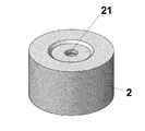
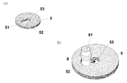
- FIG. 2 is a perspective view of a lid portion of the infusion bag pressure container of FIG. 2 is a view of a support member of the infusion bag pressure container of FIG. 2, where FIG. 2A is a perspective view and FIG. 2B is a partial perspective view for explaining a method of supporting the mouth member.
- FIG. 2 is a diagram showing a state in which the infusion bag in the infusion bag pressurizing container of FIG. 2 is pressurized and contracted.
- the schematic diagram which shows the close contact state between the end of an infusion bag and a sealing material.
- FIG. 12 is a perspective view of the support member in FIG.
- the schematic diagram for demonstrating the state which attaches the infusion bag to the support member of FIG. The schematic diagram for demonstrating the method of attaching a support member to a lid part in the infusion bag pressure container which concerns on 4th Embodiment of this invention.
- the infusion bag pressurizing device M includes an infusion bag pressurizing container C and a pressurizing means P.
- the infusion bag pressurized container C is composed of a container main body 1 and a lid 2, and the container main body 1 is composed of an accommodating portion 3 and a connecting portion 4.
- the pressurizing means P only needs to be able to introduce compressed air or other compressed gas (pressure transfer fluid) into the accommodating portion 3 and pressurize the compressed gas so as to be higher than the atmospheric pressure.
- a pressure transfer fluid booster piston connected to a vacuum piston
- a pressure transfer fluid booster bellows connected to a vacuum piston
- an electric pressurization pump a pressure accumulator bomb or a pressurizer consisting of a pressure accumulator and a low pressure regulator, vacuum.
- a pressure transfer fluid boosting piston connected to a piston such as a pressurizing device equipped with a regulator for stabilizing pressure, can be applied.
- the pressurizing means P is connected to the container main body 1 and the inside of the accommodating portion 3 via the connecting portion 4 so as to be able to pressurize.
- FIG. 1 shows a state before the lid 2 is attached to the container body 1, but in FIG. 2, the infusion bag B is housed in the container 3 and the lid 2 is attached to the container body 1.
- the state is illustrated in a schematic cross-sectional view. A state in which the infusion bag B is housed in the infusion bag pressurizing container C so as to be pressurized will be described with reference to FIGS. 2 to 4.
- the container main body 1 is provided with a male screw portion 11 in a circumferential shape on the upper portion thereof to accommodate the infusion bag B from the main body 7 side, and a connection portion provided on a side surface near the bottom of the accommodating portion 3.
- An annular step portion 12 on which a support member 5 described later is placed is provided on the inner peripheral edge of the opening portion of the accommodating portion 3.
- the lid portion 2 has a female screw portion 22 provided on the inner wall surface in a circumferential shape and a through hole 21 for inserting a hollow needle attached to the tip of the conduit tube T into the end portion 81 of the infusion bag B.
- the through hole 21 has a diameter slightly smaller than that of the end portion 81 and has a diameter that allows the hollow needle to easily pass through.
- a ring-shaped recess 23 centered on a through hole 21 is provided on the back surface side of the top plate of the lid portion 2, and a ring-shaped sealing material 6 is fitted in the recess 23.
- the sealing material 6 is a ring-shaped silicon sealing material having a taper, and prevents leakage of compressed gas in the accommodating portion 3 by abutting the sealing material 6 on the end portion 81 of the mouth member 8.
- a ring-shaped seal O is attached above the female screw portion 22 inside the lid portion 2 in order to maintain airtightness between the lid portion 2 and the accommodating portion 3.
- the mouth member 8 of the infusion bag B in the accommodating portion 3 is accommodated in the accommodating portion 3 via the support member 5.
- the configuration of the support member 5 and the method of supporting the mouth member 8 by the support member 5 will be described with reference to FIG.
- the support member 5 is a disk-shaped member and has an insertion hole 51 through which the end portion 81 of the mouth member 8 can be inserted.
- the insertion hole 51 includes a first hole 52 through which the end 81 of the mouth member 8 can be inserted, and a second hole 53 which is smaller than the first hole 52 and is connected to the first hole 52.
- the support member 5 is attached to the mouth member 8 of the infusion bag B.
- the end 81 of the mouth member 8 is inserted through the first hole 52 as shown in FIG. 4 (b), and the mouth member 8 is seconded from this state. It is translated in the direction of the hole 53 (in the direction of the arrow in the figure).
- the mouth member 8 fits into the second hole 53, and the mouth member 8 is supported by the support member 5 by the second hole 53.
- the infusion bag B in the above state is accommodated in the accommodating portion 3 from the main body portion 7 side. At that time, the support member 5 is placed on the step portion 12 of the accommodating portion 3.
- the sealing member 6 abuts and adheres to the end 81 of the infusion bag B, and the portion is sealed.
- the inside of the container body 1 is sealed, but the end 81 of the mouth member 8 of the infusion bag B is exposed through the through hole 21 and the insertion hole 51. Therefore, the hollow needle of the conduit tube T can be pierced through this portion.
- the pressurizing means P is connected to the pressurizing means P via the connecting portion 4 and the pressurizing means P is driven, the liquid in the infusion bag B can be supplied to the human body.
- FIG. 5 schematically illustrates a state in which the pressurizing means P is driven to supply the liquid in the infusion bag B into the human body via the conduit tube T.
- This figure shows, for example, a state in which air is introduced by a pressurizing means P including an electric pressurizing pump and the air is pressurized so as to be higher than the atmospheric pressure, whereby the infusion bag B is added. It is compressed by the pressure air and the main body 7 is deformed to generate wrinkles. As a result, the liquid in the infusion bag B is pushed out, and the liquid is supplied to the human body through the conduit tube T.
- the pressurized air acts directly on the infusion bag B, so that even if the infusion bag B is deformed, the inside of the infusion bag B
- the liquid pressure of the above is kept equal to the pressure of the pressurized air and the supply pressure of the pressurized air is stable, the flow rate of the infusion solution discharged from the infusion solution bag B is also stable.
- FIG. 6 is a schematic view showing a state of close contact between the end portion of the infusion bag and the sealing material 6.
- Commercially available infusion bags do not have a uniform shape, and the diameters of the ends of the mouth members vary, resulting in the ends (81, 810, 811) and the sealing material 6. The contact points of are different. Therefore, an annular taper is provided on the inner surface of the sealing material 6 of the present embodiment in order to correspond to the diameter of the end portion of various types of infusion bags.
- FIG. 6 illustrates this state, and here, three types of infusion bags are illustrated.
- FIG. 7 is a schematic cross-sectional view of the infusion bag pressure container C1 according to the second embodiment of the present invention.
- the difference from the infusion bag pressurizing container C of the first embodiment is that the lid portion 2A is configured, the tightening member 9 is screwed into the lid portion 2A, and the lid portion 2A and the tightening member 9 are rings. This is a point where the shape seal O is interposed and screwed.
- FIGS. 7 and 8 since the structure of the container main body 1 is the same as that in the first embodiment, detailed description thereof will be omitted.
- the lid portion 2A is provided with a female screw portion 22 screwed with the male screw portion 11 of the container main body 1 on the inner wall surface thereof, and further is provided with a male screw portion 22a screwed with the tightening member 9 below the female screw portion 22. ..
- the tightening member 9 is an annular member having a female screw portion 91 screwed with the male screw portion 22a of the lid portion 2A on the inner wall surface thereof, and as shown in FIG. 7, a ring-shaped seal O is interposed. It is attached to the lid 2A.
- the method is the same as that of the first embodiment until the infusion bag B is housed in the container body 1.
- the lid portion 2A and the tightening member 9 are separated from each other, the lid portion 2A is removed from the container body portion 1, and the O-ring seal O and the tightening member 9 are attached to the outer periphery of the container body portion 1. It is in a certain state. From this state, the female screw portion 22 of the lid portion 2A is screwed into the male screw portion 11, and the end portion 81 of the infusion bag B is screwed until it comes into contact with the sealing material 6. Then, from this state, the tightening member 9 is tightened to the lid portion 2A (in the direction of the arrow in the figure). Then, the tightening member 9 and the lid portion 2A are sealed by the compressed ring-shaped seal O, and the sealing material 6 and the ring-shaped seal O can prevent the leakage of the compressed air in the container body 1. can.
- the ring-shaped seal O is compressed when the lid portion 2 is screwed to the container body portion 1 in the configuration of the first embodiment. Since it is caught in the air, the frictional force makes the installation work a little difficult.
- the ring-shaped seal O is not caught in the screwing, so that the first embodiment Installation work is easier than that of the above configuration.
- FIG. 9 shows a schematic cross-sectional view of the infusion bag pressure container C2 according to the third embodiment of the present invention.
- the difference from the infusion bag pressurizing container C of the first embodiment is that the accommodating portion 3A does not have a step portion, and the other configurations are the same.
- the major differences are that the lid portion is composed of the first lid portion 2a and the second lid portion 2b, and the sealing material 6A is configured.
- the description will be made with reference to FIGS. 9 to 11, but since the structure of the container body 1A is almost the same as that in the first embodiment, detailed description thereof will be omitted.
- the first lid portion 2a includes a first cylindrical portion 220 and a second cylindrical portion 220a having a diameter smaller than that of the first cylindrical portion 220.
- a female screw portion 22 is provided on the inner wall surface of the first cylindrical portion 220, and a male screw portion 22a is provided on the outer wall surface of the second cylindrical portion 220a.
- the opening above the second cylindrical portion 220a is referred to as a through hole 21a.
- the second lid portion 2b is a cylindrical member, a female screw portion 22b on the inner wall surface thereof, a through hole 21b above it, and a ring-shaped recess centered on the through hole 21b on the back surface side of the top plate thereof. 23b is provided.
- the sealing material 6A is a disk-shaped sealing material made of, for example, silicon, and is formed in a size that can be fitted into the recess 23b.
- the infusion bag B is accommodated in the accommodating portion 3A from the main body portion 7 side.
- the second lid portion 2b with the sealing material 6A attached to the recess 23b is attached to the first lid portion 2a.
- the male screw portion 22a and the female screw portion 22b are screwed together.
- the lid portion in this state (the one in which the second lid portion 2b is attached to the first lid portion 2a) is screwed into the male screw portion 11 and the female screw portion 22 and screwed to the container body portion 1A. ..
- the end portion 81 of the mouth member 8 and the back surface side of the sealing material 6A are in contact with each other and screwed until they are pressed to some extent.
- the through holes 21a and 21b are closed with the sealing material 6A, and the inside of the container main body 1A is sealed.
- the hollow needle is inserted into the portion of the sealing material 6A exposed from the through hole 21b, and the hollow needle is inserted until it is inserted into the end 81. put in. That is, in the present embodiment, if the hollow needle is first inserted into the sealing material 6A and then the hollow needle is inserted until the end 81 is inserted as it is, the hollow needle is inserted while maintaining the sealed state inside the container body 1A. It can be inserted into the infusion bag B.
- FIG. 12 shows a schematic cross-sectional view of the infusion bag pressure container C3 according to the fourth embodiment of the present invention.
- the infusion bag pressure container C3 is composed of a container main body 1B and a lid 2B, and the container main body 1B is composed of a storage portion 3B and a connection portion 4 (same configuration as the first embodiment).
- the container main body 1B has a female screw portion 13 provided on the inner wall surface of the upper portion thereof, and a storage portion 3B for accommodating the infusion bag B from the main body 7 side and a connection portion provided on the side surface near the bottom of the accommodating portion 3B. It consists of four.
- the lid portion 2B has a male screw portion 24 provided on the outer wall surface of the lower portion thereof, a female screw portion 25 provided on the inner wall surface of the inner upper portion thereof, and the tip of the conduit tube T to the end portion 81 of the infusion bag B. It has a through hole 21 for inserting a hollow needle attached to the.
- the through hole 21 has a diameter slightly smaller than that of the end portion 81 and has a diameter that allows the hollow needle to easily pass through.
- the sealing material 6 and the recess 23 have the same configuration as that of the first embodiment, and the point that the sealing material 6 is fitted in the recess 23 is also the same as that of the first embodiment.
- the support member 50 includes a cylindrical support main body portion 5a and a handle portion 5b that is connected to the support main body portion 5a and serves as a handle when the support member 50 is attached to the lid portion 2B.
- the support main body 5a is provided with a snowball-shaped insertion hole 51 composed of a first insertion hole 52 and a second insertion hole 53 having the same configuration as that of the first embodiment.
- a male screw portion 54 screwed into the female screw portion 25 of the lid portion 2B is provided on the outer wall surface of the support main body portion 5a.
- FIG. 14 shows a state in which the infusion bag B is attached to the support member 50.
- the method of attaching the infusion bag B to the insertion hole 51 of the mouth member 8 is the same as the method in the first embodiment, and is detailed. The description is omitted.
- the support member 50 with the infusion bag B attached to the support member 50 is attached to the lid 2B by the method shown in FIG. Specifically explaining this mounting method, a support member 50 is inserted inside the lid portion 2B to which the ring-shaped seal O is mounted at the position shown in FIG. 15 so that the male screw portion 54 is screwed into the female screw portion 25. do.
- the mounting work of the support member 50 is performed by grasping the handle portion 5b by hand and rotating the male screw portion 54 so as to be screwed into the female screw portion 25.
- the support member 50 is screwed into the lid portion 2B until the sealing material 6 comes into contact with the end portion 81 of the infusion bag B and pressure is applied to some extent.
- the lid portion 2B in the above state is attached to the container main body portion 1B so that the main body portion 7 of the infusion bag B is accommodated in the accommodating portion 3B.
- the female screw portion 13 of the container body portion 1B is screwed into the male screw portion 24 of the lid portion 2B.
- the ring-shaped seal O interposed between the lid portion 2B and the accommodating portion 3B is compressed, and the inside of the accommodating portion 3B is sealed.
- Infusion bag pressurizing device C Infusion bag pressurizing container P Pressurizing means B Infusion bag O-ring shape seal (leakage prevention means) T Conduit tube 1 Container body 2 Lid 21 Through hole 25 Female threaded part 3 Accommodating part 4 Connection part 5 Support member 51 Insertion hole 52 First insertion hole 53 Second insertion hole 54 Male thread part 6 Sealing material (leakage) Preventive measures) 7 Main body 8 Mouth member 81 End 9 Tightening member
Landscapes
- Health & Medical Sciences (AREA)
- Vascular Medicine (AREA)
- Engineering & Computer Science (AREA)
- Anesthesiology (AREA)
- Biomedical Technology (AREA)
- Heart & Thoracic Surgery (AREA)
- Hematology (AREA)
- Life Sciences & Earth Sciences (AREA)
- Animal Behavior & Ethology (AREA)
- General Health & Medical Sciences (AREA)
- Public Health (AREA)
- Veterinary Medicine (AREA)
- Medical Preparation Storing Or Oral Administration Devices (AREA)
Abstract
【課題】加圧によって安定して輸液を継続し、携帯にも便利で、かつ、従来と通りの手間で輸液バックに輸液セットを装着可能とする輸液バック加圧容器及び輸液バッグ加圧装置を提供すること。 【解決手段】本発明に係る輸液バッグ加圧容器Mは、輸液バッグBを本体部7側から収容する収容部3と、収容部3に設けられ収容部3内に空気を導入し空気を大気圧より高くなるように加圧する加圧手段Pに接続する接続部4と、を有する容器本体部1と、容器本体部1と着脱可能に結合する蓋部2と、を備えるとともに、蓋部2には、容器本体部1に結合した際に口部材8の端部81に中空針を刺通可能に設けられた貫通孔21を備えており、貫通孔21から容器本体部1内に導入された空気の漏洩を防止するシール材6 を有し、加圧手段Pによって加圧され、輸液バッグBが収縮して本体部7内の液体を押し出すようにする。
Description
本発明は、点滴バッグなどの輸液バッグを収容した状態で、加圧して内部の液体を送り出し可能な輸液バッグ加圧容器及び輸液バッグ加圧装置に関する。
従来、病院などで患者の医療に用いる一般的な点滴は、点滴スタンドを用い、点滴バッグを注入位置よりも高い位置にセットして、重力による自然落下により患者の静脈へ薬液を注入する方法で行っている。このいわゆる点滴スタンド吊り下げ式は、スタンド構造がシンプルで安価であり、流量も比較的に安定しているが、設置場所の制限と移動範囲の制約があり、スタンドを持ち歩く際の転倒危険性があり、生活の不自由が強いられるといった問題がある。
その他の点滴方法として、電動輸液ポンプを利用して薬液を注入する方法もある。このいわゆる電動輸液ポンプ式は、流量精度は高いものの点滴スタンドに輸液バッグ吊るし、その下に電動輸液ポンプを配置する方法が多く、転倒の危険や生活の不自由が強いられるといった問題の解決には至っていない。また、電源やバッテリー交換を必要とし、高価で携帯に向かないといった問題がある。
前記問題を解決する他のものとして、特許文献1に記載のポータブル点滴装置もある。このポータブル点滴装置は、加圧筒(1)内にベローズ(6)を内蔵し、荷重印加手段である錘(10)または渦巻バネを利用した巻上装置(35)の力によりベローズ(6)を縮ませ、内部圧力を高める。この圧力を密閉容器(2)又は膨張バッグ(23)に導入し、圧力または膨張力により常に適正な力で安定して輸液バッグ(11)を圧迫し、中の薬液を吐出するように構成されている。
特許文献1に記載されたポータブル点滴装置によると、輸液バッグに圧力等を加えて点滴を行う装置において、ポンプやガスボンベを用いて点滴バッグに圧力を加えて点滴を行う場合のように、故障や電池切れあるいはガス欠などにより過大な圧力が発生したり輸液が停止したりすることなく、安定して輸液を継続し、携帯にも便利な点滴装置を提供することが可能である。
しかしながら、ここに開示されたポータブル点滴装置によれば、その構造上、予め導管チューブ(A12)を刺した状態で輸液バッグ(11)を密閉容器(2)内に収容し、その後、シールブッシュ(13)が取り付けてある貫通部から導管チューブ(A12)を挿通し、その後、点滴筒(3)を取り付ける。あるいは、貫通部に導管チューブ(A12)を予め挿通した状態で、一端側の中空針を輸液バッグ(11)に刺し、もう一端は点滴筒(3)に取り付ける必要がある。
このようにすれば、密閉容器(2)内の密閉性を保持出来るわけであるが、一般的には、これら輸液バッグに取り付けるチューブ類は、中空針、点滴筒(チャンバー)、クレンメ、導管チューブ及び注射針がすべて取り付けられた輸液セットとして販売されていることが多く、このポータブル点滴装置を使用した場合には、貫通部に導管チューブを挿通するために中空針あるいは点滴筒を一旦取り外す必要があり、手間がかかるといった新たな問題が生ずる。実際、ほとんどの市販の輸液セットは、中空針と点滴筒と導管チューブとが一体に構成されており、取り外しが不可能な一体構造であるため、このポータブル点滴装置に適用できない。
すなわち、このポータブル点滴装置の構造においては、密閉容器(2)内の密閉性を求めることにより、通常であれば、単に輸液バッグに中空針を挿入すればよいだけの簡単な作業を手間のかかる作業にしてしまうことになってしまうのである。
そこで、本発明はこのような問題を解決するためになされたものであり、その目的とするところは、加圧によって安定して輸液を継続し、携帯にも便利で、かつ、従来と通りの手間で輸液バックに輸液セットを装着可能とする輸液バック加圧容器及び輸液バッグ加圧装置を提供することにある。
前記の目的を達成するため、本発明は、液体が収容された本体部と、前記本体部と連接し輸液を排出する筒状の口部材とからなる輸液バッグを加圧可能に収容する輸液バッグ加圧容器であって、前記輸液バッグを前記本体部側から収容する収容部と、前記収容部に設けられ前記収容部内に圧力伝達流体を導入し、前記圧力伝達流体を大気圧より高くなるように加圧する加圧手段に接続する接続部と、を有する容器本体部と、前記容器本体部と着脱可能に結合する蓋部と、を備えるとともに、前記蓋部には、前記容器本体部に結合した際に、前記口部材の端部に中空針を刺通可能に設けられた貫通孔を備えており、前記貫通孔から前記容器本体部内に導入された圧力伝達流体の漏洩を防止する漏洩防止手段を有し、
前記加圧手段によって加圧され前記輸液バッグが収縮して前記本体部内の液体を押し出すようにすることを特徴とする。
前記加圧手段によって加圧され前記輸液バッグが収縮して前記本体部内の液体を押し出すようにすることを特徴とする。
また、前記輸液バッグを収容した際に、前記口部材を支持する支持部材を有していてもよい。
また、前記支持部材は、円板状であって前記口部材の端部が挿通可能な挿通孔を有し、前記挿通孔は、前記端部が挿通可能な第1の孔と、前記第1の孔より小さい孔であって前記第1の孔と連接する第2の孔からなり、前記口部材を前記第1の孔に挿通した後、前記口部材を前記第2の孔にスライドさせることにより前記口部材が前記支持部材に支持されるように構成してもよい。
また、前記漏洩防止手段は、内側面にテーパのついたリング状のシール材あるいは円板状のシール材であって、前記口部材の端部に当接させることにより前記容器本体部内の圧力伝達流体の漏洩を防止するように構成してもよい。
また、前記漏洩防止手段は、内側面にテーパのついたリング状のシール材と、リング形状シールとからなり、前記蓋部と締め込み可能に接続される締め込み部材をさらに備え、前記蓋部と前記締め込み部材とは、前記リング形状シールを介在させて接続されるように構成してもよい。
また、前記支持部材の外周には雄ネジ部を備え、前記蓋部の内壁面には前記雄ネジ部に結合可能な雌ネジ部を備え、前記支持部材は、前記口部材の端部に前記漏洩防止手段を当接させることにより前記蓋部に結合されるように構成してもよい。
前記の目的を達成するため、本発明の輸液バッグ加圧装置は、前記いずれかに記載の輸液バッグ加圧容器と、真空ピストンに連結された圧力伝達流体昇圧ピストンからなる加圧手段から構成されていることを特徴とする。
また、前記加圧手段は、真空ピストンに連結された圧力伝達流体昇圧ベローズ、電動加圧ポンプあるいは蓄圧ボンベもしくは蓄圧容器と低圧レギュレータであってもよい。
また、前記加圧手段は、真空ピストンに連結された圧力伝達流体昇圧ピストンであって、圧力を安定化するレギュレータを備えた加圧手段であってもよい。
本発明に係る輸液バッグ加圧容器によれば、液体が収容された本体部と、前記本体部と連接し輸液を排出する筒状の口部材とからなる輸液バッグを加圧可能に収容する輸液バッグ加圧容器であって、前記輸液バッグを前記本体部側から収容する収容部と、前記収容部に設けられ前記収容部内に圧力伝達流体を導入し、前記圧力伝達流体を大気圧より高くなるように加圧する加圧手段に接続する接続部と、を有する容器本体部と、前記容器本体部と着脱可能に結合する蓋部と、を備えるとともに、前記蓋部には、前記容器本体部に結合した際に前記口部材の端部に中空針を刺通可能に設けられた貫通孔を備えており、前記貫通孔から前記容器本体部内に導入された圧力伝達流体の漏洩を防止する漏洩防止手段を有し、前記加圧手段によって加圧され前記輸液バッグが収縮して前記本体部内の液体を押し出すように構成した。また、本発明に係る輸液バッグ加圧装置によれば、前記構成の輸液バッグ加圧容器と、前記構成の加圧手段とからなるように構成した。これにより、加圧によって安定して輸液を継続し、携帯にも便利で、かつ、従来通りの手間で輸液バックに輸液セットを装着可能とするという効果がある。
以下、本発明を実施するための形態について、図面を参照しながら詳細に説明する。
<第1実施形態>
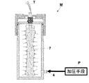
図1に示すように、本発明の第1実施形態に係る輸液バッグ加圧装置Mは、輸液バッグ加圧容器Cと加圧手段Pとからなる。輸液バッグ加圧容器Cは、容器本体部1と蓋部2からなり、容器本体部1は、収容部3と接続部4からなる。
図1に示すように、本発明の第1実施形態に係る輸液バッグ加圧装置Mは、輸液バッグ加圧容器Cと加圧手段Pとからなる。輸液バッグ加圧容器Cは、容器本体部1と蓋部2からなり、容器本体部1は、収容部3と接続部4からなる。
加圧手段Pは、収容部3内に圧縮空気またはその他の圧縮気体(圧力伝達流体)を導入し圧縮気体を大気圧より高くなるように加圧することができればよいので、ここでは簡略的に図示してあり、例えば、真空ピストンに連結された圧力伝達流体昇圧ピストン、真空ピストンに連結された圧力伝達流体昇圧ベローズ、電動加圧ポンプ、蓄圧ボンベもしくは蓄圧容器と低圧レギュレータからなる加圧装置、真空ピストンに連結された圧力伝達流体昇圧ピストンであって圧力を安定化するレギュレータを備えた加圧装置などが適用可能である。この加圧手段Pは、接続部4を介して容器本体部1と収容部3内を加圧可能に接続される。
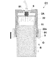
図1には蓋部2が容器本体部1に取り付ける前の状態が図示されているが、図2は、輸液バッグBが収容部3内に収容され、蓋部2が容器本体部1に取り付けられた状態が模式断面図的に図示されている。輸液バッグBが輸液バッグ加圧容器C内に加圧可能に収容される状態を図2乃至図4を参照して説明する。
容器本体部1は、その上部に円周状に雄ネジ部11が設けられ輸液バッグBを本体部7側から収容する収容部3と、収容部3の底部近傍の側面に設けられた接続部4からなり、収容部3の開口部分内側周縁には後述する支持部材5を載置する円環状の段部12が設けられている。
蓋部2は、円周状に内壁面に設けられた雌ネジ部22と、輸液バッグBの端部81へ導管チューブTの先端に取り付けられた中空針を刺入させるための貫通孔21を有する。貫通孔21は、端部81とよりも少し小さい直径で前記中空針を通しやすい径で構成されている。
蓋部2の天板の裏面側には、貫通孔21を中心とするリング状の凹部23が設けられており、凹部23にはリング状のシール材6が嵌め込まれている。シール材6は、テーパのついたリング状のシリコン製のシール材であって、口部材8の端部81に当接させることにより収容部3内の圧縮気体の漏洩を防止する。蓋部2の内側の雌ネジ部22上方には、蓋部2と収容部3との間の気密性を保持するために、リング形状シールOが取り付けられている。
収容部3内の輸液バッグBの口部材8は、支持部材5を介して収容部3内に収容されている。次いで、支持部材5の構成及び支持部材5による口部材8の支持方法について図4を参照して説明する。
図4(a)に示すとおり、支持部材5は円板状の部材であって口部材8の端部81が挿通可能な挿通孔51を有している。挿通孔51は、口部材8の端部81が挿通可能な第1の孔52と、第1の孔52より小さい孔であって第1の孔52と連接する第2の孔53からなる、雪だるま形状の挿通孔51である。
以上が本発明の第1実施形態に係る輸液バッグ加圧装置M及び輸液バッグ加圧容器Cの構成であるが、次に、輸液バッグBを輸液バッグ加圧容器Cに取り付ける方法について図2及び図4(b)を参照して説明する。
まず、輸液バッグBの口部材8に支持部材5を取り付ける。この取り付け方について図4(b)を参照して説明すると、口部材8の端部81を第1の孔52から図4(b)のように挿通し、この状態から口部材8を第2の孔53の方向(図中矢印方向)に平行移動させる。すると、口部材8は第2の孔53に篏合し、口部材8は第2の孔53によって支持部材5に支持される。
上記状態の輸液バッグBを本体部7側から収容部3内に収容する。その際、支持部材5は収容部3の段部12に載置される。
この状態から、収容部3の雄ネジ部11と蓋部2の雌ネジ部22を螺合させ、シール材6が取り付けられた蓋部2を容器本体部1に締め込んで行く。
すると、シール部材6が輸液バッグBの端部81に当接、密着し、当該部分がシールされる。この締め込み作業が終了すると、容器本体部1内は密閉状態となるが、輸液バッグBの口部材8の端部81は、貫通孔21及び挿通孔51を介して露出状態となっていることから、この部分に導管チューブTの中空針を刺通することができる。そして、接続部4を介して加圧手段Pに接続し、加圧手段Pを駆動させれば、人体内に輸液バッグB内の液体を供給することができる。
図5は、加圧手段Pを駆動させて輸液バッグB内の液体を導管チューブTを介して人体内に供給している状態を模式的に図示したものである。この図は、例えば、電動加圧ポンプからなる加圧手段Pによって空気を導入し、空気を大気圧より高くなるように加圧している状態を図示しており、これにより、輸液バッグBが加圧空気に圧縮されて本体部7が変形してしわが発生し、その結果、輸液バッグB内の液体が押し出されて、導管チューブTを介して人体内に液体が供給される。
このように、輸液バッグ加圧装置M及び輸液バッグ加圧容器Cを使用すれば、輸液バッグBに対して加圧空気が直接作用するので、輸液バッグBが変形しても、輸液バッグB内の液体圧力が加圧空気の圧力に等しく保たれており、加圧空気の供給圧が安定さえすれば、輸液バッグBから吐出される輸液流量も安定する。
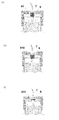
図6は、輸液バッグの端部とシール材6との密着状態を示す模式図である。市販されている輸液バッグは、その形状が統一されているわけではなく、口部材の端部の径の大きさも様々であり、その結果、端部(81、810、811)とシール材6との当接点は異なってくる。そのため、様々なタイプの輸液バッグの端部の径に対応すべく、本実施形態のシール材6内側面には円環状のテーパが設けられている。その状態を図示しているのが図6であり、ここでは3つのタイプの輸液バッグを図示している。
<第2実施形態>
図7には、本発明の第2実施形態に係る輸液バッグ加圧容器C1の断面的模式図が図示されている。第1実施形態の輸液バッグ加圧容器Cとの相違点は、蓋部2Aの構成と、蓋部2Aと螺合する締め込み部材9を有する点と、蓋部2Aと締め込み部材9がリング形状シールOを介在させて螺合される点である。以下、図7及び図8を使用して説明するが、容器本体部1の構成は第1実施形態におけるものと同一の構成なので、その詳細な説明は省略する。
図7には、本発明の第2実施形態に係る輸液バッグ加圧容器C1の断面的模式図が図示されている。第1実施形態の輸液バッグ加圧容器Cとの相違点は、蓋部2Aの構成と、蓋部2Aと螺合する締め込み部材9を有する点と、蓋部2Aと締め込み部材9がリング形状シールOを介在させて螺合される点である。以下、図7及び図8を使用して説明するが、容器本体部1の構成は第1実施形態におけるものと同一の構成なので、その詳細な説明は省略する。
蓋部2Aは、その内壁面に容器本体部1の雄ネジ部11と螺合する雌ネジ部22を備え、さらに、その下方に締め込み部材9と螺合する雄ネジ部22aを備えている。
締め込み部材9は、その内壁面に蓋部2Aの雄ネジ部22aと螺合する雌ネジ部91を備えた円環状部材であり、図7に示すように、リング形状シールOを介在させて蓋部2Aに取り付けられる。
このように構成された輸液バッグ加圧容器C1における輸液バッグBの収容方法について図7及び図8を参照して説明する。
容器本体部1内に輸液バッグBを収容するまでは第1実施形態と同様の方法である。この際、蓋部2Aと締め込み部材9が互いに切り離してあって、蓋部2Aが容器本体部1から取り外され、OリングシールOと締め込み部材9が容器本体部1の外周に付帯させてある状態である。この状態から蓋部2Aの雌ネジ部22を雄ネジ部11に螺合させ、輸液バッグBの端部81がシール材6に当接するまでネジ止めして行く。そして、この状態から締め込み部材9を蓋部2Aに締め込んで行く(図中矢印方向)。すると、締め込み部材9と蓋部2Aとの間は圧縮されたリング形状シールOによってシールされ、シール材6とリング形状シールOによって、容器本体部1内の圧縮空気の漏洩を防止することができる。
第1実施形態においてもリング形状シールOによって該漏洩防止を図ることが可能であるが、第1実施形態の構成では蓋部2を容器本体部1にネジ止めする際にリング形状シールOが圧縮されながら巻き込まれていくので、その摩擦力によって取り付け作業が多少困難となる。一方、本実施形態のような構成とすれば、蓋部2Aに締め込み部材9をネジ止めする際には、リング形状シールOがネジ止めの際に巻き込まれることはないので、第1実施形態の構成のものよりも取付作業が容易となる。
<第3実施形態>
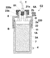
図9には、本発明の第3実施形態に係る輸液バッグ加圧容器C2の断面的模式図が図示されている。第1実施形態の輸液バッグ加圧容器Cとの相違点は、収容部3Aにおいては段部が形成されていない点だけでその他の構成は同一である。大きな相違点としては、蓋部が第1の蓋部2aと第2の蓋部2bが構成されている点と、シール材6Aの構成である。以下、図9乃至図11を参照して説明するが、容器本体部1Aの構成は第1実施形態におけるものとほぼ同一の構成なので、その詳細な説明は省略する。
図9には、本発明の第3実施形態に係る輸液バッグ加圧容器C2の断面的模式図が図示されている。第1実施形態の輸液バッグ加圧容器Cとの相違点は、収容部3Aにおいては段部が形成されていない点だけでその他の構成は同一である。大きな相違点としては、蓋部が第1の蓋部2aと第2の蓋部2bが構成されている点と、シール材6Aの構成である。以下、図9乃至図11を参照して説明するが、容器本体部1Aの構成は第1実施形態におけるものとほぼ同一の構成なので、その詳細な説明は省略する。
第1の蓋部2aは、第1の円筒部220と、第1の円筒部220よりも小径の第2の円筒部220aとからなる。第1の円筒部220の内壁面には雌ネジ部22を備え、第2の円筒部220aの外壁面には雄ネジ部22aが設けられている。なお、本実施形態においては説明の便宜上、第2の円筒部220aの上方の開口部を貫通孔21aと称する。
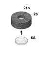
第2の蓋部2bは円筒状の部材であり、その内壁面には雌ネジ部22b、その上方には貫通孔21b及びその天板の裏面側に貫通孔21bを中心とするリング状の凹部23bが設けられている。
シール材6Aは、円板状の例えばシリコン製のシール材であり、凹部23bに嵌め込み可能な大きさに形成されている。
このように構成された輸液バッグ加圧容器C2における輸液バッグBの収容方法について図9乃至図11を参照して説明する。
まず、収容部3A内に輸液バッグBを本体部7側から収容する。次に、凹部23bにシール材6Aを装着した状態の第2の蓋部2bを第1の蓋部2aに取り付ける。具体的には、雄ネジ部22aと雌ネジ部22bを螺合させる。この状態の蓋部(第1の蓋部2aに第2の蓋部2bを取り付けた状態のもの)を雄ネジ部11と雌ネジ部22を螺合させて、容器本体部1Aにネジ止めする。この際、口部材8の端部81とシール材6Aの裏面側が当接し、ある程度押し付けられるまでネジ止めする。このような取り付け作業を行うと貫通孔21a、21bがシール材6Aで塞がれて容器本体部1A内が密閉状態となる。この状態から口部材8の端部81に中空針を刺し入れるためには、貫通孔21bから露出しているシール材6Aの部分に中空針を刺し、端部81に挿通するまで中空針を刺し入れる。すなわち、本実施形態においては、中空針をシール材6Aにまず刺し入れ、そのまま端部81を挿通するまで中空針を刺し入れれば、容器本体部1A内の密閉状態を保持しつつ、中空針を輸液バッグBに挿通することができる。
<第4実施形態>
図12には、本発明の第4実施形態に係る輸液バッグ加圧容器C3の断面的模式図が図示されている。輸液バッグ加圧容器C3は、容器本体部1Bと蓋部2Bからなり、容器本体部1Bは、収容部3Bと接続部4(第1実施形態と同一構成)からなる。
図12には、本発明の第4実施形態に係る輸液バッグ加圧容器C3の断面的模式図が図示されている。輸液バッグ加圧容器C3は、容器本体部1Bと蓋部2Bからなり、容器本体部1Bは、収容部3Bと接続部4(第1実施形態と同一構成)からなる。
容器本体部1Bは、その上部の内壁面に雌ネジ部13が設けられ、輸液バッグBを本体部7側から収容する収容部3Bと、収容部3Bの底部近傍の側面に設けられた接続部4からなる。
蓋部2Bは、その下方部外壁面に設けられた雄ネジ部24と、その内側上方部の内壁面に設けられた雌ネジ部25と、輸液バッグBの端部81へ導管チューブTの先端に取り付けられた中空針を刺入させるための貫通孔21を有する。貫通孔21は、端部81よりも少し小さい直径で前記中空針を通しやすい径で構成されている。なお、シール材6及び凹部23は第1実施形態のものと同一の構成であり、凹部23にシール材6が嵌め込まれている点も第1実施形態と同様である。
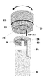
図13に示すとおり支持部材50は、円筒状の支持本体部5aと、支持本体部5aに連接され支持部材50を蓋部2Bに装着する際に持ち手となる持ち手部5bとからなる。支持本体部5aには第1実施形態と同様の構成の第1の挿通孔52及び第2の挿通孔53からなる雪だるま形状の挿通孔51が設けられている。支持本体部5aの外壁面には蓋部2Bの雌ネジ部25に螺合する雄ネジ部54が設けられている。
支持部材50に輸液バッグBを装着する状態を図示したのが図14であるが、輸液バッグBの口部材8の挿通孔51への装着方法に関しては第1実施形態における方法と同一なので詳細な説明は省略する。
このように構成された輸液バッグ加圧容器C3における輸液バッグBの収納方法について、図12乃至図15を参照して説明する。
まず、図14に示した方法により輸液バッグBが支持部材50に装着された状態の支持部材50を蓋部2Bに取り付ける。この取り付け方法を具体的に説明すると、図15に示す位置にリング形状シールOが取り付けられた蓋部2Bの内側に、雌ネジ部25に雄ネジ部54を螺合させるよう支持部材50を挿入する。この支持部材50の取付作業は、手で持ち手部5bを把持し、雌ネジ部25に雄ネジ部54を螺合させるよう回転させることにより行う。この取り付けの際、第1実施形態と同様、輸液バッグBの端部81にシール材6が当接しある程度圧力がかかるような状態まで支持部材50を蓋部2Bに螺合させる。
次いでこの状態から、輸液バッグBの本体部7を収容部3B内に収容するようにして前記状態の蓋部2Bを容器本体部1Bに取り付ける。具体的には、容器本体部1Bの雌ネジ部13を蓋部2Bの雄ネジ部24に螺合させる。すると、蓋部2Bと収容部3Bの間に介在するリング形状シールOが圧縮され収容部3B内が密閉状態となる。
M 輸液バッグ加圧装置
C 輸液バッグ加圧容器
P 加圧手段
B 輸液バッグ
O リング形状シール(漏洩防止手段)
T 導管チューブ
1 容器本体部
2 蓋部
21 貫通孔
25 雌ネジ部
3 収容部
4 接続部
5 支持部材
51 挿通孔
52 第1の挿通孔
53 第2の挿通孔
54 雄ネジ部
6 シール材(漏洩防止手段)
7 本体部
8 口部材
81 端部
9 締め込み部材
C 輸液バッグ加圧容器
P 加圧手段
B 輸液バッグ
O リング形状シール(漏洩防止手段)
T 導管チューブ
1 容器本体部
2 蓋部
21 貫通孔
25 雌ネジ部
3 収容部
4 接続部
5 支持部材
51 挿通孔
52 第1の挿通孔
53 第2の挿通孔
54 雄ネジ部
6 シール材(漏洩防止手段)
7 本体部
8 口部材
81 端部
9 締め込み部材
Claims (11)
- 液体が収容された本体部と、前記本体部と連接し輸液を排出する筒状の口部材とからなる輸液バッグを加圧可能に収容する輸液バッグ加圧容器であって、
前記輸液バッグを前記本体部側から収容する収容部と、前記収容部に設けられ前記収容部内に圧力伝達流体を導入し、前記圧力伝達流体を大気圧より高くなるように加圧する加圧手段に接続する接続部と、を有する容器本体部と、
前記容器本体部と着脱可能に結合する蓋部と、を備えるとともに、
前記蓋部には、前記容器本体部に結合した際に、前記口部材の端部に中空針を刺通可能に設けられた貫通孔を備えており、
前記貫通孔から前記容器本体部内に導入された圧力伝達流体の漏洩を防止する漏洩防止手段を有し、
前記加圧手段によって加圧され前記輸液バッグが収縮して前記本体部内の液体を押し出すようにすること
を特徴とする輸液バッグ加圧容器。 - 前記輸液バッグを収容した際に、前記口部材を支持する支持部材を有することを特徴とする請求項1に記載の輸液バッグ加圧容器。
- 前記支持部材は、円板状であって前記口部材の端部が挿通可能な挿通孔を有し、前記挿通孔は、前記端部が挿通可能な第1の孔と、前記第1の孔より小さい孔であって前記第1の孔と連接する第2の孔からなり、前記口部材を前記第1の孔に挿通した後、前記口部材を前記第2の孔にスライドさせることにより前記口部材が前記支持部材に支持されることを特徴とする請求項2に記載の輸液バッグ加圧容器。
- 前記漏洩防止手段は、内側面にテーパのついたリング状のシール材あるいは円板状のシール材であって、前記口部材の端部に当接させることにより前記容器本体部内の圧力伝達流体の漏洩を防止することを特徴とする請求項2に記載の輸液バッグ加圧容器。
- 前記漏洩防止手段は、内側面にテーパのついたリング状のシール材と、リング形状シールとからなり、
前記蓋部と締め込み可能に接続される締め込み部材をさらに備え、
前記蓋部と前記締め込み部材とは、前記リング形状シールを介在させて接続されることを特徴とする請求項1あるいは2に記載の輸液バッグ加圧容器。 - 前記支持部材の外周には雄ネジ部を備え、
前記蓋部の内壁面には前記雄ネジ部に結合可能な雌ネジ部を備え、
前記支持部材は、前記口部材の端部に前記漏洩防止手段を当接させることにより前記蓋部に結合されることを特徴とする請求項4に記載の輸液バッグ加圧容器。 - 請求項1乃至6のいずれか1項に記載の輸液バッグ加圧容器と、真空ピストンに連結された圧力伝達流体昇圧ピストンからなる加圧手段から構成されていること
を特徴とする輸液バッグ加圧装置。 - 請求項1乃至6のいずれか1項に記載の輸液バッグ加圧容器と、真空ピストンに連結された圧力伝達流体昇圧ベローズからなる加圧手段から構成されていること
を特徴とする輸液バッグ加圧装置。 - 請求項1乃至6のいずれか1項に記載の輸液バッグ加圧容器と、電動加圧ポンプからなる加圧手段から構成されていること
を特徴とする輸液バッグ加圧装置。 - 請求項1乃至6のいずれか1項に記載の輸液バッグ加圧容器と、蓄圧ボンベ若しくは蓄圧容器と低圧レギュレータからなる加圧手段から構成されていること
を特徴とする輸液バッグ加圧装置。 - 請求項1乃至6のいずれか1項に記載の輸液バッグ加圧容器と、真空ピストンに連結された圧力伝達流体昇圧ピストンであって、圧力を安定化するレギュレータを備えた加圧手段から構成されていること
を特徴とする輸液バッグ加圧装置。
Priority Applications (1)
| Application Number | Priority Date | Filing Date | Title |
|---|---|---|---|
| PCT/JP2020/010088 WO2021181476A1 (ja) | 2020-03-09 | 2020-03-09 | 輸液バッグ加圧容器、輸液バッグ加圧装置 |
Applications Claiming Priority (1)
| Application Number | Priority Date | Filing Date | Title |
|---|---|---|---|
| PCT/JP2020/010088 WO2021181476A1 (ja) | 2020-03-09 | 2020-03-09 | 輸液バッグ加圧容器、輸液バッグ加圧装置 |
Publications (1)
| Publication Number | Publication Date |
|---|---|
| WO2021181476A1 true WO2021181476A1 (ja) | 2021-09-16 |
Family
ID=77671259
Family Applications (1)
| Application Number | Title | Priority Date | Filing Date |
|---|---|---|---|
| PCT/JP2020/010088 Ceased WO2021181476A1 (ja) | 2020-03-09 | 2020-03-09 | 輸液バッグ加圧容器、輸液バッグ加圧装置 |
Country Status (1)
| Country | Link |
|---|---|
| WO (1) | WO2021181476A1 (ja) |
Citations (3)
| Publication number | Priority date | Publication date | Assignee | Title |
|---|---|---|---|---|
| JPH09262286A (ja) * | 1996-03-28 | 1997-10-07 | Terumo Corp | 点滴方法及び点滴装置並びに点滴容器 |
| CN201510595U (zh) * | 2009-03-05 | 2010-06-23 | 王�锋 | 气压便携式多功能安全输液装置 |
| JP2018203339A (ja) * | 2017-06-05 | 2018-12-27 | 有限会社ラブディポット | 高気密保存容器用キャップ |
-
2020
- 2020-03-09 WO PCT/JP2020/010088 patent/WO2021181476A1/ja not_active Ceased
Patent Citations (3)
| Publication number | Priority date | Publication date | Assignee | Title |
|---|---|---|---|---|
| JPH09262286A (ja) * | 1996-03-28 | 1997-10-07 | Terumo Corp | 点滴方法及び点滴装置並びに点滴容器 |
| CN201510595U (zh) * | 2009-03-05 | 2010-06-23 | 王�锋 | 气压便携式多功能安全输液装置 |
| JP2018203339A (ja) * | 2017-06-05 | 2018-12-27 | 有限会社ラブディポット | 高気密保存容器用キャップ |
Similar Documents
| Publication | Publication Date | Title |
|---|---|---|
| JP2527954B2 (ja) | 高粘性流体送り出し装置 | |
| US6276567B1 (en) | Pressurized fluid delivery apparatus | |
| EP0253949A2 (en) | Syringe assembly having a flexible cover for the plunger rod | |
| US4248223A (en) | Self-priming parenteral administering apparatus | |
| US3064652A (en) | Transfusion equipment | |
| AU2011258245B2 (en) | Connector cap for priming a transfusion line | |
| DK2802377T3 (en) | Pressure regulating bottle adapter and method | |
| US2452643A (en) | Disposable venoclysis set | |
| US20090260627A1 (en) | Liquid anesthetic container and delivery system | |
| CN103764185A (zh) | 负压伤口治疗仪 | |
| US4392499A (en) | Adaptor for facilitating blood sampling procedures | |
| JPH0451966A (ja) | 薬液連続注入器 | |
| JPH02501709A (ja) | 冷凍乾燥物質等の貯蔵容器 | |
| CN118555923A (zh) | 筒包装系统和方法 | |
| US20160243317A1 (en) | Syringe receptacle | |
| JP3474313B2 (ja) | 加圧式比較電極 | |
| JPS6359972A (ja) | 埋設用カテ−テル装置 | |
| JPWO1995000101A1 (ja) | 医療用容器 | |
| US3948266A (en) | Needleless hypodermic injector | |
| JPS61164564A (ja) | 自動注射液注入装置 | |
| US20100125252A1 (en) | Safety syringe | |
| CN205460072U (zh) | 一种甲状腺手术用负压引流器 | |
| JP2024515185A (ja) | バイオ医薬製品のためのフィッティング接続でのガス漏れの可能性を検出するためのシーリングデバイスおよび方法 | |
| US8636693B2 (en) | Propellant pillow | |
| CN211536150U (zh) | 球囊加压装置 |
Legal Events
| Date | Code | Title | Description |
|---|---|---|---|
| 121 | Ep: the epo has been informed by wipo that ep was designated in this application |
Ref document number: 20923969 Country of ref document: EP Kind code of ref document: A1 |
|
| NENP | Non-entry into the national phase |
Ref country code: DE |
|
| 122 | Ep: pct application non-entry in european phase |
Ref document number: 20923969 Country of ref document: EP Kind code of ref document: A1 |
|
| NENP | Non-entry into the national phase |
Ref country code: JP |